EP3282126B1 - Electronic control device for a refrigerant compressor - Google Patents
Electronic control device for a refrigerant compressorDownload PDFInfo
- Publication number
- EP3282126B1 EP3282126B1EP17183095.3AEP17183095AEP3282126B1EP 3282126 B1EP3282126 B1EP 3282126B1EP 17183095 AEP17183095 AEP 17183095AEP 3282126 B1EP3282126 B1EP 3282126B1
- Authority
- EP
- European Patent Office
- Prior art keywords
- operating torque
- during
- compression mechanism
- positive operating
- electronic control
- Prior art date
- Legal status (The legal status is an assumption and is not a legal conclusion. Google has not performed a legal analysis and makes no representation as to the accuracy of the status listed.)
- Active
Links
- 239000003507refrigerantSubstances0.000titleclaimsdescription109
- 238000007906compressionMethods0.000claimsdescription159
- 230000006835compressionEffects0.000claimsdescription158
- 230000007246mechanismEffects0.000claimsdescription122
- 238000000034methodMethods0.000claimsdescription44
- 230000002829reductive effectEffects0.000claimsdescription37
- 230000001105regulatory effectEffects0.000claimsdescription17
- 230000001133accelerationEffects0.000claimsdescription15
- 230000001276controlling effectEffects0.000claimsdescription10
- 230000008569processEffects0.000description20
- 230000035939shockEffects0.000description13
- 238000010586diagramMethods0.000description12
- 238000001816coolingMethods0.000description10
- 230000001846repelling effectEffects0.000description6
- 230000000694effectsEffects0.000description5
- 230000009467reductionEffects0.000description4
- 230000008901benefitEffects0.000description3
- 230000003247decreasing effectEffects0.000description3
- 230000005284excitationEffects0.000description3
- 230000010355oscillationEffects0.000description3
- 238000004804windingMethods0.000description3
- 238000013459approachMethods0.000description2
- 230000007423decreaseEffects0.000description2
- 238000001514detection methodMethods0.000description2
- 230000000670limiting effectEffects0.000description2
- 230000002441reversible effectEffects0.000description2
- 230000002238attenuated effectEffects0.000description1
- 230000033228biological regulationEffects0.000description1
- 239000003990capacitorSubstances0.000description1
- 230000008859changeEffects0.000description1
- 238000004891communicationMethods0.000description1
- 238000010276constructionMethods0.000description1
- 230000036461convulsionEffects0.000description1
- 239000002826coolantSubstances0.000description1
- 238000013016dampingMethods0.000description1
- 230000001419dependent effectEffects0.000description1
- 238000013461designMethods0.000description1
- 238000005516engineering processMethods0.000description1
- 230000003116impacting effectEffects0.000description1
- 230000006698inductionEffects0.000description1
- 238000007689inspectionMethods0.000description1
- 230000002045lasting effectEffects0.000description1
- 238000005259measurementMethods0.000description1
- 238000005057refrigerationMethods0.000description1
- 230000000630rising effectEffects0.000description1
- 239000000725suspensionSubstances0.000description1
- 230000007704transitionEffects0.000description1
- 238000011144upstream manufacturingMethods0.000description1
Images


Classifications
- F—MECHANICAL ENGINEERING; LIGHTING; HEATING; WEAPONS; BLASTING
- F04—POSITIVE - DISPLACEMENT MACHINES FOR LIQUIDS; PUMPS FOR LIQUIDS OR ELASTIC FLUIDS
- F04B—POSITIVE-DISPLACEMENT MACHINES FOR LIQUIDS; PUMPS
- F04B39/00—Component parts, details, or accessories, of pumps or pumping systems specially adapted for elastic fluids, not otherwise provided for in, or of interest apart from, groups F04B25/00 - F04B37/00
- F04B39/0027—Pulsation and noise damping means
- F—MECHANICAL ENGINEERING; LIGHTING; HEATING; WEAPONS; BLASTING
- F04—POSITIVE - DISPLACEMENT MACHINES FOR LIQUIDS; PUMPS FOR LIQUIDS OR ELASTIC FLUIDS
- F04B—POSITIVE-DISPLACEMENT MACHINES FOR LIQUIDS; PUMPS
- F04B49/00—Control, e.g. of pump delivery, or pump pressure of, or safety measures for, machines, pumps, or pumping installations, not otherwise provided for, or of interest apart from, groups F04B1/00 - F04B47/00
- F04B49/20—Control, e.g. of pump delivery, or pump pressure of, or safety measures for, machines, pumps, or pumping installations, not otherwise provided for, or of interest apart from, groups F04B1/00 - F04B47/00 by changing the driving speed
- F—MECHANICAL ENGINEERING; LIGHTING; HEATING; WEAPONS; BLASTING
- F04—POSITIVE - DISPLACEMENT MACHINES FOR LIQUIDS; PUMPS FOR LIQUIDS OR ELASTIC FLUIDS
- F04B—POSITIVE-DISPLACEMENT MACHINES FOR LIQUIDS; PUMPS
- F04B49/00—Control, e.g. of pump delivery, or pump pressure of, or safety measures for, machines, pumps, or pumping installations, not otherwise provided for, or of interest apart from, groups F04B1/00 - F04B47/00
- F04B49/02—Stopping, starting, unloading or idling control
- F—MECHANICAL ENGINEERING; LIGHTING; HEATING; WEAPONS; BLASTING
- F04—POSITIVE - DISPLACEMENT MACHINES FOR LIQUIDS; PUMPS FOR LIQUIDS OR ELASTIC FLUIDS
- F04B—POSITIVE-DISPLACEMENT MACHINES FOR LIQUIDS; PUMPS
- F04B49/00—Control, e.g. of pump delivery, or pump pressure of, or safety measures for, machines, pumps, or pumping installations, not otherwise provided for, or of interest apart from, groups F04B1/00 - F04B47/00
- F04B49/06—Control using electricity
- F—MECHANICAL ENGINEERING; LIGHTING; HEATING; WEAPONS; BLASTING
- F25—REFRIGERATION OR COOLING; COMBINED HEATING AND REFRIGERATION SYSTEMS; HEAT PUMP SYSTEMS; MANUFACTURE OR STORAGE OF ICE; LIQUEFACTION SOLIDIFICATION OF GASES
- F25B—REFRIGERATION MACHINES, PLANTS OR SYSTEMS; COMBINED HEATING AND REFRIGERATION SYSTEMS; HEAT PUMP SYSTEMS
- F25B1/00—Compression machines, plants or systems with non-reversible cycle
- F25B1/02—Compression machines, plants or systems with non-reversible cycle with compressor of reciprocating-piston type
- F—MECHANICAL ENGINEERING; LIGHTING; HEATING; WEAPONS; BLASTING
- F25—REFRIGERATION OR COOLING; COMBINED HEATING AND REFRIGERATION SYSTEMS; HEAT PUMP SYSTEMS; MANUFACTURE OR STORAGE OF ICE; LIQUEFACTION SOLIDIFICATION OF GASES
- F25B—REFRIGERATION MACHINES, PLANTS OR SYSTEMS; COMBINED HEATING AND REFRIGERATION SYSTEMS; HEAT PUMP SYSTEMS
- F25B31/00—Compressor arrangements
- F25B31/02—Compressor arrangements of motor-compressor units
- F25B31/023—Compressor arrangements of motor-compressor units with compressor of reciprocating-piston type
- F—MECHANICAL ENGINEERING; LIGHTING; HEATING; WEAPONS; BLASTING
- F25—REFRIGERATION OR COOLING; COMBINED HEATING AND REFRIGERATION SYSTEMS; HEAT PUMP SYSTEMS; MANUFACTURE OR STORAGE OF ICE; LIQUEFACTION SOLIDIFICATION OF GASES
- F25B—REFRIGERATION MACHINES, PLANTS OR SYSTEMS; COMBINED HEATING AND REFRIGERATION SYSTEMS; HEAT PUMP SYSTEMS
- F25B49/00—Arrangement or mounting of control or safety devices
- F25B49/02—Arrangement or mounting of control or safety devices for compression type machines, plants or systems
- F25B49/022—Compressor control arrangements
- H—ELECTRICITY
- H02—GENERATION; CONVERSION OR DISTRIBUTION OF ELECTRIC POWER
- H02P—CONTROL OR REGULATION OF ELECTRIC MOTORS, ELECTRIC GENERATORS OR DYNAMO-ELECTRIC CONVERTERS; CONTROLLING TRANSFORMERS, REACTORS OR CHOKE COILS
- H02P23/00—Arrangements or methods for the control of AC motors characterised by a control method other than vector control
- H02P23/04—Arrangements or methods for the control of AC motors characterised by a control method other than vector control specially adapted for damping motor oscillations, e.g. for reducing hunting
- H—ELECTRICITY
- H02—GENERATION; CONVERSION OR DISTRIBUTION OF ELECTRIC POWER
- H02P—CONTROL OR REGULATION OF ELECTRIC MOTORS, ELECTRIC GENERATORS OR DYNAMO-ELECTRIC CONVERTERS; CONTROLLING TRANSFORMERS, REACTORS OR CHOKE COILS
- H02P6/00—Arrangements for controlling synchronous motors or other dynamo-electric motors using electronic commutation dependent on the rotor position; Electronic commutators therefor
- H02P6/06—Arrangements for speed regulation of a single motor wherein the motor speed is measured and compared with a given physical value so as to adjust the motor speed
- H—ELECTRICITY
- H02—GENERATION; CONVERSION OR DISTRIBUTION OF ELECTRIC POWER
- H02P—CONTROL OR REGULATION OF ELECTRIC MOTORS, ELECTRIC GENERATORS OR DYNAMO-ELECTRIC CONVERTERS; CONTROLLING TRANSFORMERS, REACTORS OR CHOKE COILS
- H02P6/00—Arrangements for controlling synchronous motors or other dynamo-electric motors using electronic commutation dependent on the rotor position; Electronic commutators therefor
- H02P6/08—Arrangements for controlling the speed or torque of a single motor
- H—ELECTRICITY
- H02—GENERATION; CONVERSION OR DISTRIBUTION OF ELECTRIC POWER
- H02P—CONTROL OR REGULATION OF ELECTRIC MOTORS, ELECTRIC GENERATORS OR DYNAMO-ELECTRIC CONVERTERS; CONTROLLING TRANSFORMERS, REACTORS OR CHOKE COILS
- H02P7/00—Arrangements for regulating or controlling the speed or torque of electric DC motors
- F—MECHANICAL ENGINEERING; LIGHTING; HEATING; WEAPONS; BLASTING
- F04—POSITIVE - DISPLACEMENT MACHINES FOR LIQUIDS; PUMPS FOR LIQUIDS OR ELASTIC FLUIDS
- F04B—POSITIVE-DISPLACEMENT MACHINES FOR LIQUIDS; PUMPS
- F04B2201/00—Pump parameters
- F04B2201/02—Piston parameters
- F04B2201/0201—Position of the piston
- F—MECHANICAL ENGINEERING; LIGHTING; HEATING; WEAPONS; BLASTING
- F04—POSITIVE - DISPLACEMENT MACHINES FOR LIQUIDS; PUMPS FOR LIQUIDS OR ELASTIC FLUIDS
- F04B—POSITIVE-DISPLACEMENT MACHINES FOR LIQUIDS; PUMPS
- F04B2201/00—Pump parameters
- F04B2201/12—Parameters of driving or driven means
- F04B2201/1202—Torque on the axis
- F—MECHANICAL ENGINEERING; LIGHTING; HEATING; WEAPONS; BLASTING
- F04—POSITIVE - DISPLACEMENT MACHINES FOR LIQUIDS; PUMPS FOR LIQUIDS OR ELASTIC FLUIDS
- F04B—POSITIVE-DISPLACEMENT MACHINES FOR LIQUIDS; PUMPS
- F04B2203/00—Motor parameters
- F04B2203/02—Motor parameters of rotating electric motors
- F04B2203/0207—Torque
- F—MECHANICAL ENGINEERING; LIGHTING; HEATING; WEAPONS; BLASTING
- F04—POSITIVE - DISPLACEMENT MACHINES FOR LIQUIDS; PUMPS FOR LIQUIDS OR ELASTIC FLUIDS
- F04B—POSITIVE-DISPLACEMENT MACHINES FOR LIQUIDS; PUMPS
- F04B2203/00—Motor parameters
- F04B2203/02—Motor parameters of rotating electric motors
- F04B2203/0209—Rotational speed
- F—MECHANICAL ENGINEERING; LIGHTING; HEATING; WEAPONS; BLASTING
- F04—POSITIVE - DISPLACEMENT MACHINES FOR LIQUIDS; PUMPS FOR LIQUIDS OR ELASTIC FLUIDS
- F04B—POSITIVE-DISPLACEMENT MACHINES FOR LIQUIDS; PUMPS
- F04B35/00—Piston pumps specially adapted for elastic fluids and characterised by the driving means to their working members, or by combination with, or adaptation to, specific driving engines or motors, not otherwise provided for
- F04B35/04—Piston pumps specially adapted for elastic fluids and characterised by the driving means to their working members, or by combination with, or adaptation to, specific driving engines or motors, not otherwise provided for the means being electric
- F—MECHANICAL ENGINEERING; LIGHTING; HEATING; WEAPONS; BLASTING
- F25—REFRIGERATION OR COOLING; COMBINED HEATING AND REFRIGERATION SYSTEMS; HEAT PUMP SYSTEMS; MANUFACTURE OR STORAGE OF ICE; LIQUEFACTION SOLIDIFICATION OF GASES
- F25B—REFRIGERATION MACHINES, PLANTS OR SYSTEMS; COMBINED HEATING AND REFRIGERATION SYSTEMS; HEAT PUMP SYSTEMS
- F25B2400/00—General features or devices for refrigeration machines, plants or systems, combined heating and refrigeration systems or heat-pump systems, i.e. not limited to a particular subgroup of F25B
- F25B2400/05—Compression system with heat exchange between particular parts of the system
- F25B2400/052—Compression system with heat exchange between particular parts of the system between the capillary tube and another part of the refrigeration cycle
- F—MECHANICAL ENGINEERING; LIGHTING; HEATING; WEAPONS; BLASTING
- F25—REFRIGERATION OR COOLING; COMBINED HEATING AND REFRIGERATION SYSTEMS; HEAT PUMP SYSTEMS; MANUFACTURE OR STORAGE OF ICE; LIQUEFACTION SOLIDIFICATION OF GASES
- F25B—REFRIGERATION MACHINES, PLANTS OR SYSTEMS; COMBINED HEATING AND REFRIGERATION SYSTEMS; HEAT PUMP SYSTEMS
- F25B2400/00—General features or devices for refrigeration machines, plants or systems, combined heating and refrigeration systems or heat-pump systems, i.e. not limited to a particular subgroup of F25B
- F25B2400/05—Compression system with heat exchange between particular parts of the system
- F25B2400/054—Compression system with heat exchange between particular parts of the system between the suction tube of the compressor and another part of the cycle
- F—MECHANICAL ENGINEERING; LIGHTING; HEATING; WEAPONS; BLASTING
- F25—REFRIGERATION OR COOLING; COMBINED HEATING AND REFRIGERATION SYSTEMS; HEAT PUMP SYSTEMS; MANUFACTURE OR STORAGE OF ICE; LIQUEFACTION SOLIDIFICATION OF GASES
- F25B—REFRIGERATION MACHINES, PLANTS OR SYSTEMS; COMBINED HEATING AND REFRIGERATION SYSTEMS; HEAT PUMP SYSTEMS
- F25B2500/00—Problems to be solved
- F25B2500/12—Sound
- F—MECHANICAL ENGINEERING; LIGHTING; HEATING; WEAPONS; BLASTING
- F25—REFRIGERATION OR COOLING; COMBINED HEATING AND REFRIGERATION SYSTEMS; HEAT PUMP SYSTEMS; MANUFACTURE OR STORAGE OF ICE; LIQUEFACTION SOLIDIFICATION OF GASES
- F25B—REFRIGERATION MACHINES, PLANTS OR SYSTEMS; COMBINED HEATING AND REFRIGERATION SYSTEMS; HEAT PUMP SYSTEMS
- F25B2500/00—Problems to be solved
- F25B2500/13—Vibrations
- F—MECHANICAL ENGINEERING; LIGHTING; HEATING; WEAPONS; BLASTING
- F25—REFRIGERATION OR COOLING; COMBINED HEATING AND REFRIGERATION SYSTEMS; HEAT PUMP SYSTEMS; MANUFACTURE OR STORAGE OF ICE; LIQUEFACTION SOLIDIFICATION OF GASES
- F25B—REFRIGERATION MACHINES, PLANTS OR SYSTEMS; COMBINED HEATING AND REFRIGERATION SYSTEMS; HEAT PUMP SYSTEMS
- F25B2500/00—Problems to be solved
- F25B2500/27—Problems to be solved characterised by the stop of the refrigeration cycle
- F—MECHANICAL ENGINEERING; LIGHTING; HEATING; WEAPONS; BLASTING
- F25—REFRIGERATION OR COOLING; COMBINED HEATING AND REFRIGERATION SYSTEMS; HEAT PUMP SYSTEMS; MANUFACTURE OR STORAGE OF ICE; LIQUEFACTION SOLIDIFICATION OF GASES
- F25B—REFRIGERATION MACHINES, PLANTS OR SYSTEMS; COMBINED HEATING AND REFRIGERATION SYSTEMS; HEAT PUMP SYSTEMS
- F25B2600/00—Control issues
- F25B2600/02—Compressor control
- F25B2600/025—Compressor control by controlling speed
- F25B2600/0253—Compressor control by controlling speed with variable speed
- Y—GENERAL TAGGING OF NEW TECHNOLOGICAL DEVELOPMENTS; GENERAL TAGGING OF CROSS-SECTIONAL TECHNOLOGIES SPANNING OVER SEVERAL SECTIONS OF THE IPC; TECHNICAL SUBJECTS COVERED BY FORMER USPC CROSS-REFERENCE ART COLLECTIONS [XRACs] AND DIGESTS
- Y02—TECHNOLOGIES OR APPLICATIONS FOR MITIGATION OR ADAPTATION AGAINST CLIMATE CHANGE
- Y02B—CLIMATE CHANGE MITIGATION TECHNOLOGIES RELATED TO BUILDINGS, e.g. HOUSING, HOUSE APPLIANCES OR RELATED END-USER APPLICATIONS
- Y02B30/00—Energy efficient heating, ventilation or air conditioning [HVAC]
- Y02B30/70—Efficient control or regulation technologies, e.g. for control of refrigerant flow, motor or heating
Definitions
- the present inventionalso relates to methods of controlling a reciprocating refrigerant compressor, the compression mechanism of which is driven by a drive unit at an operating torque, and more particularly to a method of controlling the drive unit of the reciprocating refrigerant compressor.
- Rotational speed variable refrigerant compressorshave the advantage that they can be more specifically tailored to the cooling requirements of the object to be cooled by, for example, in the case of lower cooling requirements at a lower rotational speed and in Case of increased cooling requirement, can be operated with a correspondingly increased rotational speed.
- variable speed reciprocating refrigerant compressorsconsist essentially of a drive unit and a compression mechanism in the form of a piston reciprocating in a cylinder housing between an upper and lower dead center, which is connected via a connecting rod with a crankshaft, which in turn is rotationally rigidly coupled to a rotor of the drive unit.
- the drive unitis typically a brushless DC motor. It is possible to determine the relative position of the rotor of the DC motor and thus also the rotational speed of the motor or of the compression mechanism on the basis of the induced in the motor winding back-voltage (induction back voltage). This method eliminates the need for separate sensors and is therefore particularly easy to implement and less prone to interference.
- the problems with low-speed operation in normal, controlled operationinclude noise technology.
- the gas forcescause a reduced load moment compared to the compression phase. This leads to an increase in the speed of the compression mechanism during the suction phase.
- a load torque varying over the crank angleacts on the compression mechanism, wherein the fluctuation width of the load torque mainly depends on the pressure ratio in the refrigerant circuit and leads to different angular accelerations and thus to a non-uniform speed of the compression mechanism during one crankshaft revolution.
- thisis mounted together with drive unit via spring elements in a housing.
- the natural frequencies of this vibration systemare depending on the compressor type between 5 Hz and 16 Hz.
- the described, undesired noise emissions of a reciprocating refrigerant compressor at low rotational speedsoccur not only in normal, regulated operation but especially during the stopping process, where these low rotational speeds must be driven through.
- the suspension processusually takes place as follows: If the target temperature of the object to be cooled, for example a refrigerator compartment of a refrigerator, is reached after a correspondingly continuous normal, regulated operating phase of the refrigerant compressor, the electronic control device of the refrigerator sends a signal to the electronic control device of the refrigerant compressor with which it is informed that no more cooling power is available is needed because the target temperature is reached. From the prior art it is known that then the electronic control device of the refrigerant compressor shuts off the drive (shutdown) and the stopping process begins.
- crankshaft of the compression mechanismalso passes through each complete revolutions starting at the top dead center (crank angle 0 °) even after the switch-off, wherein initially a suction phase (correctly: suction and remindexpansionsphase) is traversed, during which refrigerant is sucked into the cylinder.
- This suction phaseends, theoretically when the cylinder has reached the bottom dead center (crank angle 180 °).
- the compression phase(correctly: compression and ejection phase during which the in-cylinder refrigerant is compressed and ejected out of the cylinder) begins the compression phase theoretically when the piston has reached top dead center (crank angle 360 °)
- crank angle 360 °the actual compression of the refrigerant starts only at a crank angle of about 210 ° (depending on the refrigerant compressor, the pressure conditions, the valve design, etc.) but in any case after 180 ° and the suction phase at about 30 °, but in any case after the upper dead center.
- Switching off the drive unit of the refrigerant compressor at a shutdown timeinitiates the stalling process and causes the compression mechanism to be in a non-powered state (with no operating torque) and only continues to rotate due to its inertia until it has come to a complete stop, i. H. its rotational speed is 0. Colloquially, one could also say that the refrigerant compressor "leaks".
- the compression mechanism / drive unitrotates solely due to the kinetic energy that they have at the time of turn-off as well as the inertia. They spin so uncontrollably and their rotational speed behavior depends on the on the Compression mechanism acting load torque.
- the load torqueleads to a reduction in the rotational speed of the non-driven refrigerant compressor, so that the kinetic energy of the compression mechanism is getting lower, depending on the pressure conditions in the refrigerant circuit, may no longer be sufficient to overcome the load torque (limiting rotational speed).
- the situationmay occur that the kinetic energy of the compression mechanism / drive unit is no longer sufficient to overcome the load torque and the piston of the compression mechanism again towards lower Dead center is pushed back, the direction of rotation of the compression mechanism reverses.
- the load torque greatly varying over the crank anglealso leads to the risk that from a limiting rotational speed of the compression stroke can not be completed and the compression mechanism strikes back in the opposite direction, whereby the vibration system additionally excited and the spring elements be additionally deflected, which in turn leads to an increased probability of impact of the compression mechanism / drive unit.
- the object of the inventionis therefore to provide a control system comprising a refrigerant compressor and an electronic control device for the reciprocating refrigerant compressor and to provide a method for controlling a reciprocating refrigerant compressor, which control system or method allows the operation of a reciprocating refrigerant compressor even at low rotational speeds, without causing excessive Deflection of the spring elements and resulting increased noise emissions comes.
- a further object of the inventionis to provide a control system comprising a refrigerant compressor and an electronic control device for a reciprocating refrigerant compressor and a method for controlling a reciprocating refrigerant compressor, which control system or method enables a silenced optimized stopping of the reciprocating refrigerant compressor without a braking torque to the compression mechanism must be created.
- Another object of the inventionis to provide a control system comprising a refrigerant compressor and an electronic control device for a reciprocating refrigerant compressor and a method for controlling a reciprocating refrigerant compressor, which control system or method, the operation of a reciprocating refrigerant compressor even at low rotational speeds, in particular when passing through such low rotational speeds during the stopping process, without the risk of reversing the direction of rotation and associated, a hitch is.
- Another object of the inventionis to be able to tailor the spring elements, by means of which the refrigerant compressor is mounted in the housing, more specifically to the occurring vibrations of the compression mechanism.
- An additional object of the inventionis to provide a control system comprising a refrigerant compressor and an electronic control device for a reciprocating refrigerant compressor and a method for controlling a reciprocating refrigerant compressor, which control system allows the operation of a reciprocating refrigerant compressor at a constant speed to the due to the increased load torque during To dampen the compression phase acting on the compression mechanism shocks, while at the same time the rotational speed can be reduced or increased.
- Another object of the inventionis to provide a control system comprising a refrigerant compressor and an electronic control device for a reciprocating refrigerant compressor, and a method for controlling a reciprocating refrigerant compressor, which control system enables the rotational speed of the compression mechanism to be successively low-speed during the stopping process reduce so that the drive unit can be switched off after reaching the low speed, without causing after switching off in the no-drive phase, possibly occurring shocks during the compression phase, a deflection of the spring elements, which is greater than the maximum allowable deflection at which just does not take place a striking of the compression mechanism / drive unit on the housing.
- a control systemcomprising a refrigerant compressor and an electronic control device for a reciprocating refrigerant compressor, which at least comprises a drive unit, a compression mechanism operatively connected to the drive unit, with at least one in a cylinder of a cylinder block between a lower and a top dead center and moving, crankshaft driven piston, wherein the electronic control device is adapted to detect and control the rotational speed of the drive unit and / or regulate the piston position, achieved by the electronic control means being adapted to operate the To drive the compression mechanism via the drive unit such that, for the duration of more than one crankshaft revolution having control period, at several crankshaft revolutions, vorzu During each crankshaft revolution of the control period ( ⁇ t) at least one drive angle section and at least one running angle section is provided and wherein the compression mechanism during the at least one drive angle section is exposed to a positive operating torque and during the at least one running angle section to a positive operating torque reduced positive operating torque or no positive operating torque ,
- the positive and / or reduced positive operating torquemay either remain constant or vary during the drive angle section and / or running angle section, in practice, due to the widespread constant voltage control, a variation of the positive operating torque or reduced positive operating torque occurs within narrow limits.
- the control device according to the invention of the control system according to the inventionmakes it possible to control the compression mechanism such that the load torque varying over the crank angle can be at least partially compensated by an equally varying, positive operating torque, wherein the electronic control device is set up such that the positive operating torque at least once , based on one revolution of the crankshaft, varies over a control period comprising a plurality, preferably consecutive, preferably 5 to 15 consecutive crankshaft revolutions.
- the positive operating torquecan vary between a maximum value, which is essentially dependent on the drive unit and the value zero.
- the tuningmay be made such that the at least one drive angle portion is provided within that operating phase of the refrigerant compressor in which an increased load torque acts on the compression mechanism (compression phase), and the at least one run angle portion is provided in that operating phase of the refrigerant compressor in which a relative to the Operating phase with increased load torque reduced load torque acting on the compression mechanism (suction phase).
- the compression mechanisminstead of the reduced positive operating torque is exposed to no positive operating torque during the at least one running angle section. In this case, it is even possible to apply a braking torque instead of the positive operating torque to the compression mechanism.
- the duration of the control perioddepends on the requirements for the uniformity of the rotational movement of the compression mechanism and may either correspond to the entire operating period of the refrigerant compressor, or only a part thereof.
- the control periodstarts when a signal of the electronic control device of a refrigerator, the achievement of a target temperature in a refrigerator signaled and ends simultaneously with the shutdown of the drive unit (switch-off).
- the electronic control device of the control systemis also adapted to reduce the rotational speed of the drive unit and thus of the compression mechanism during the control period, although per crankshaft revolution over a certain crank angle range selectively applies a positive operating torque to the compression mechanism.
- a constant reduction of the rotational speed of the compression mechanismcan be achieved thereby.
- this low operating torqueallows the rotational speed of the compression mechanism to practically not increase during the running angle portion, which allows the use of the electronic control device according to the invention, in particular for uniformly reducing the rotational speed before the drive is switched off.
- the electronic control device of the control systemis adapted to provide a plurality of drive angle sections and a plurality of running angle sections alternately during a crankshaft revolution.
- the individual drive and running angle sectionscan be of different sizes, thus cover different crank angles and be tuned together with the ratio between positive operating torque and reduced positive operating torque completely to the course of the load torque, so that the nonuniformity of the speed over the crank angle not only approximate but can be almost completely compensated and the compression mechanism rotates very smoothly even at low rotational speeds.
- the electronic control device of the control systemis adapted to provide exactly one drive angle section and exactly one running angle section during a complete crankshaft rotation, in which case preferably drive angle section and running angle section together a crankshaft revolution, ie 360 °.
- Thisis a particularly simple way of controlling, in which the operating torque of the drive unit is increased during a crankshaft revolution exactly once and is reduced again during the remaining crankshaft revolution, preferably reduced to the value described above, or is completely suspended ,
- exactly one drive angle sectionis provided during a crank angle of 220 ° to 360 °, particularly preferably during a crank angle of 270 ° to 360 °.
- the pistonis in the compression phase and supplying the positive operating torque in this phase during a crank angle between 220 ° and 360 ° is sufficient in most cases practice to operate at low rotational speeds of the compression mechanism acting on this due to the load torque To sufficiently damp shocks to avoid excessive deflections of the spring elements.
- the supply of a positive operating torque in this portion of the crank anglemay also be used to prevent the piston from reversing if the kinetic energy of the compression mechanism and drive unit is no longer sufficient to overcome the load torque in the de-energized state.
- the electronic control device of the control system according to the inventionis adapted to provide the one or more drive angle sections with positive operating torque when the piston is basically between a lower and a top dead center in a compression phase, because thereby the piston can very precisely according to the acting on him Load torque to be driven. Even if the compression mechanism is to slow down its total rotational speed in order to be shut down as a result, by providing the drive angle portion (s) during the compression phase, it is possible to drive the piston just enough to just complete the compression phase without any danger is that this recoils due to a lack of sufficient kinetic energy.
- the electronic control device of the control system according to the inventioncan provide the Laufwinkelabitese with reduced positive operating torque or without positive operating torque when the piston is between an upper and a lower dead center in a suction phase.
- the compression mechanismis characterized in the suction phase no or very little drive by the drive unit.
- the electronic control deviceis set up to switch the drive unit de-energized at a switch-off time so that it no longer generates positive operating torque in order to allow the compression mechanism to coast to a standstill.
- the electronic control deviceis set up such that it provides the control period immediately before the switch-off time.
- the rotational speed of the compression mechanismcan be downshifted to a very low rotational speed with the advantages described above and the refrigerant compressor then shut down
- the electronic control devicepreferably being adapted to select the switch-off time such that the kinetic energy of the unit consisting of compression mechanism and the drive unit is sufficient at the switch-off time to allow the piston to overcome at least the next top dead center following the switch-off time and / or the piston of the compression mechanism to reach the next top dead center following the switch-off time and before it reaches the top dead center further bottom dead center comes to a standstill and / or that the piston of the compression mechanism after the next top dead center following the switch-off time and before Erreic hen a subsequent to this next top dead center crank angle of 220 ° comes to a standstill.
- the electronic control device of the control systemis adapted to provide the positive operating torque of each drive period and the positive operating torque of each runtime section decreased for each crank angle of one crankshaft revolution of the control period such that it corresponds to the load torque Lm acting on the compression mechanism at the respective crank angle.
- the at least one reference positionis provided during a crank angle of 220 ° to 360 °, particularly preferably during a crank angle of 270 ° to 360 °.
- the rotational speed of the reciprocating refrigerant compressoris reduced or increased during the control period.
- control periodis provided immediately before a switch-off, after which the drive unit is de-energized, preferably to start the control period, when a signal of the electronic control device of a refrigerator, reaching a target temperature signaled in a refrigerator.
- Fig.1 2shows a schematic representation of a reciprocating refrigerant compressor 1 connected to an electrical power supply 12 and regulated by an electronic control device 13 in a per se known coolant circuit with a condenser 2 of a throttle device 3 and an evaporator 4.
- the refrigeranttakes up heat in the evaporator 4 from the refrigerator compartment, whereby this is cooled.
- the vaporized refrigerantis compressed via the compression mechanism 5 of the reciprocating refrigerant compressor 1 to a higher temperature and subsequently liquefied again in the condenser 2 to finally be fed via the throttle device 3 back to the evaporator 4 of the refrigerator.
- the electronic control device 13communicates the refrigerant compressor 1 with an electronic control device 14 of a refrigerator 15.
- a communication optionis not considered essential to the invention, because it is also conceivable that the electronic control device 13 communicates with a refrigerator 15, the itself no own electronic control device but only a thermostat.
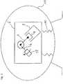
- Fig.2time a schematic view of the compression mechanism 5 consisting of a driven by a drive unit 18 crankshaft 6, a connecting rod 7 and a cylinder block 8 movable up and down piston 9.
- the compression mechanism 5is mounted via spring elements 10 in a housing 11, which spring elements 10th absorb and balance the oscillations of the unit consisting of the compression mechanism 5 and the drive unit 18 occurring due to the rotation of the crankshaft 6 and the movements of the piston 9.
- the drive unit 18 controlled by the electronic control device 13is a rotational speed variable drive unit 18, typically a brushless DC motor whose rotational speed can be controlled by the electronic control device 13.
- the detection of the actual rotational speed required for the regulation of the rotational speedtakes place by detecting the countervoltage induced in the motor winding, so that no further sensors are required, although the electronic control device 13 according to the invention of a control system according to the invention can of course also cooperate with separate sensors for rotational speed measurement, such as Hall sensors.
- the electronic control device 14 of the refrigerator 15detects that the refrigerator room temperature is rising, and sends a signal (usually a frequency signal) to the electronic controller 13 of the refrigerant compressor 1, informing the latter that cooling capacity is needed, and then supplying the refrigerant compressor 1 accordingly
- Their programmingcontrols and regulates to deliver (more or less) cooling performance.
- the electronic control device 13 of the refrigerant compressor 1will start this to compress the refrigerant and remove heat from the cold room and the target temperature reach again.
- This "starting"initiates the start phase.
- the refrigerant compressor 1, specifically its drive unit 18,is accelerated to a specific rotational speed predetermined by the electronic control device 13 of the refrigerant compressor 1. Reaching this rotational speed completes the starting phase. At this time, the target temperature is usually not reached yet.
- the refrigerant compressorthen enters the normal, regulated operating phase. This continues as long as the refrigerant compressor 1 is turned on or slightly more technical formulated, as long as the refrigerant is supplied via the compression mechanism 5 energy and the drive unit 18 of the refrigerant compressor 1 generates an operating torque.
- the compression mechanism 5may rotate at different rotational speeds during this normal, controlled phase of operation, depending on whether more or less heat is to be withdrawn from the cold room.
- the electronic control device 14 of the refrigerator 15will require more cooling power from the refrigerant compressor 1 due to the inflowing warm air, so that the electronic control device 13 of the refrigerant compressor 1 will control the rotational speed of the refrigerator Drive unit 18 and thus of the compression mechanism 5 is increased in order to be able to carry away the heat flowing into the cooling chamber.
- the increase in the rotational speedis associated with an increased energy requirement of the refrigerant compressor 1. If the electronic control device 14 of the refrigerator 15 that the current refrigerator compartment temperature approaches the target temperature, the electronic control device 14 of the refrigerator 15 is a corresponding signal to the electronic control device 13 of the Send refrigerant compressor 1 to demand less cooling power and not "overshoot" beyond the target temperature and slowly approach it. The electronic control device 13 of the refrigerant compressor 1, in turn, will reduce the rotational speed of the drive unit 18 / the compression mechanism 5 due to this requirement.
- the target temperaturesends the electronic control device 14 of the refrigerator 15, a signal to the electronic control device 13 of the refrigerant compressor 1, with which this is communicated that the target temperature is reached.
- the electronic control device 13 of the refrigerant compressor 1then switches off the drive unit 18 (switch-off time AZ).
- the shutdown of the drive unit 18causes the compression mechanism 5 together with the drive unit 18 is in a non-powered state and continues to rotate only due to the inertia until the rotational speed is 0. Colloquially, one could also say that the refrigerant compressor "leaks".
- shocks exerted on the compression mechanism 5 by the load torque during the compression phaseoccur, which repeat with each crankshaft revolution and may coincide with the natural frequency of the vibration system formed by the spring elements 10 at low rotational speeds, thereby increasing their deflection such that it may come to touch between the unit consisting of compression mechanism 5 and drive unit 18 with the housing 11, whereby unwanted noise emissions are generated.
- FIG. 12is a graph of the history of the load torque Lm versus the crank angle ⁇ during a normal, controlled phase of operation of a reciprocating refrigerant compressor known in the prior art
- Drive unit 18drives the compression mechanism 5 with an operating torque Bm. It was assumed that the crankshaft rotates clockwise. The direction of rotation thus takes place from 0 ° (top dead center) to 360 ° (top dead center).
- the load moment Lmis shortly before the piston 9 reaches the top dead center in the compression phase, ie at about 330 ° and is at the beginning of the suction phase, ie in the present case at about 10 ° negative, ie. that the load moment Lm in this portion of the suction phase (re-expansion phase) even supports the rotation of the compression mechanism 5.
- FIG. 12is a graph showing the angular acceleration ⁇ of the crankshaft 6 versus the crank angle ⁇ as a result of the relationship between the load torque Lm and the operating torque Bm, as in FIG Fig. 3 shown, is applied.
- the angular acceleration ⁇varies in the present embodiment between the values of about -3400 rad / s 2 and about +1000 rad / s 2 .
- This circumstancecauses, despite applied operating torque Bm with respect to a crankshaft revolution, the rotation of the compression mechanism 5, in particular the crankshaft 6 is a very non-uniform and in the range of a crank angle of about 330 °, the load moment Lm exerts a shock on the compression mechanism 5,
- Each of the crankshaft revolutionsrepeats itself and generates the oscillations already described in detail above, with the negative effects also already described, with the load moment Lm increasing with decreasing rotational speed ⁇ .
- the electronic control device 13 theretois set up to actively vary the operating torque Bm during a control period ⁇ t at least once per crankshaft revolution by increasing the power supply of the drive unit 18 during a drive angle section ⁇ with respect to the remaining crankshaft revolution.
- Figure 5shows that off Figure 3 known curve of the load torque Lm during a crankshaft revolution, but with the invention by the electronic control device 13 applied, schematically illustrated operating torque Bm, which is regulated so that exactly one drive angle section .DELTA. ⁇ is provided, during which the drive unit 18, the compression mechanism 5 with a positive operating torque Bm drives and precisely a running angle section ⁇ during which the drive unit 18 drives the compression mechanism 5 with respect to the positive operating torque reduced positive operating torque Bmv or alternatively does not drive (see dashed line of the Bmv), the transitions between the positive operating torque Bm and Although reduced operating torque Bmv are indeed marked, but not extra provided with a reference numeral but for the sake of simplicity, the positive operating torque Bm are attributed.
- the beginning of the compression phase KPis indicated by the reference numeral 16 and the beginning of the suction phase by the reference numeral 17.
- the electronic control device 13 of the refrigerant compressor 1controls the drive unit 18 so that the drive angle section ⁇ is entirely or largely within the compression phase.
- the drive angle section .DELTA..phi.May be greater or smaller than that shown in the exemplary embodiment.
- Figure 6shows which a diagram relating to the angular acceleration ⁇ of the crankshaft 6 over the crank angle ⁇ when using an electronic control device 13 according to the invention of the control system according to the invention with an operating torque curve according to Figure 5 shows this, both over a defined crank angle applied as well as magnitude controlled driving the compression mechanism 5 during a crankshaft revolution with two different operating torques Bm and Bmv to the angular acceleration ⁇ the crankshaft 6 over the crank angle ⁇ (and thus the speed above the crank angle ) runs much more balanced than is the case with conventional reciprocating refrigerant compressors according to the prior art and in Figure 4 is shown.
- the speed in the crank angle range between 30 ° and 210 °is approximately constant, the crankshaft experiences no acceleration.
- the crankshaftis first accelerated and then braked again, so that the uniformity of the speed of the crankshaft is thereby influenced only insignificantly and thus also the impact on the compression mechanism shocks are much lower than previously Case was.
- the course of the positive operating torque Bm and the reduced positive operating torque Bmv together, with which the compression mechanism 5 is drivenpractically corresponds to the course of the load torque Lm, to which the compression mechanism 5 is exposed, however with opposite signs and, where appropriate, sections larger or smaller amounts, depending on whether the rotational speed of the compression mechanism is to be kept constant, should be increased or reduced.
- Figure 7shows such a matched combination of positive operating torque Bm and reduced positive operating torque Bmv.
- the positive operating torque Bmvaries both in the drive angle section ⁇ and in the running angle section ⁇ , so that the course of the load torque Lm is simulated with the opposite sign.
- Figure 8shows that in this case the angular acceleration ⁇ the crankshaft 6 is constant, resulting in a constant speed over the crank angle ⁇ and thus also a constant rotational speed.
- the profile of the positive operating torque Bm and the reduced positive operating torque Bmvis not adjusted to the course of the load torque Lm that the first curve practically corresponds to a mirrored load torque Lm (see Figure 7 and 8th ) because this leads to a constant speed and constant turning speed overall.
- the rotational speedis to be slowed down regardless of the fluctuation of the rotational speed above the crank angle ⁇ , so that the electronic control device 13 exerts the operating torque Bm and the reduced positive operating torque Bmv so that the shocks occurring from the load torque Lm during the compression phase on the Compression mechanism are largely dissipated, the rotational speed but decreases in total.
- the positive operating torque Bmcan be selected such that, at least in the compression phase, sufficient drive is always present to prevent the piston 9 from repelling.
- the drive angle section ⁇already starts in the suction phase of the piston 9, so that the piston 9 is supplied with sufficient momentum before entering the compression phase to overcome the following top dead center in any case without being knocked back by the load moment Lm.
- the compression mechanism 5can slow down its total rotational movement to a complete stop or until a time at which a possible repelling of the piston 9 has no negative noise effects.
- the electronic control device 13 in the course of reducing the rotational speed for the purpose of preparing the shutdown of the drive unit 18is capable of at least such a drive angle section .DELTA..PHI. And at least one such Laufwinkelabêt .DELTA.T at least during a several crankshaft revolutions lasting control period .DELTA.t provided.
- Figure 9shows a diagram relating to the course of the load torque Lm, the positive operating torque Bm, the reduced positive operating torque Bmv, the rotational speed ⁇ and the angular acceleration ⁇ of the compression mechanism 5 over several crankshaft revolutions and over a control period .DELTA.t wherein the rotational speed ⁇ is continuously reduced until the drive is switched off at the turn-off time AZ at a rotational speed below 450 U / min, preferably below 250 U / min.
- the shutdownis preferably carried out during the compression phase.
- the compression mechanismdrives continuously with a positive operating torque Bm during a drive angle section .DELTA..PHI and a contrasting reduced positive operating torque Bmv during a running angle section ⁇ , wherein the positive operating torque Bm remains preferably constant at each crankshaft revolution until the turn-off time AZ, possibly slightly increasing to compensate for the speed loss and thus the reduction of the kinetic energy.
- the positive operating torque Bmremains constant, but is thus applied with decreasing rotational speed in any case over a longer period of time, thus also during an increasing crank angle.
- the compression mechanismis always slightly more or slightly longer or both “dived” to overcome the load torque and the "lost" kinetic energy of the unit consisting of compression mechanism 5 and drive unit 18 to compensate.
- the switching off of the drive unit 18takes place only at a very low rotational speed below 450 U / min, preferably below 250 U / min.
- the control period .DELTA.tends in the present embodiment with the turn-off time AZ or in other words is the Control period .DELTA.t the Abschaltzeittician AZ immediately upstream.
- Figure 10corresponds to Figure 9 but with the difference that the abscissa is not the crank angle ⁇ is plotted but the time t. It can be seen that as the rotational speed ⁇ decreases, the period of time over which the positive operating torque Bm is applied increases.
Landscapes
- Engineering & Computer Science (AREA)
- Mechanical Engineering (AREA)
- General Engineering & Computer Science (AREA)
- Physics & Mathematics (AREA)
- Thermal Sciences (AREA)
- Power Engineering (AREA)
- Control Of Positive-Displacement Pumps (AREA)
- Compressor (AREA)
Description
Translated fromGermanDie vorliegende Erfindung bezieht sich auf ein Steuerungssystem umfassend einen Kältemittelkompressor und eine elektronische Steuerungseinrichtung für den Kältemittelkompressor, welcher Kältemittelkompressor zumindest umfasst
- eine Antriebseinheit,
- einen mit der Antriebseinheit in Wirkverbindung stehenden Kompressionsmechanismus, mit zumindest einem sich in einem Zylinder eines Zylinderblocks zwischen einem unteren und einem oberen Totpunkt hin und her bewegenden, über eine Kurbelwelle angetriebenen Kolben,
wobei die elektronische Steuerungseinrichtung, dazu eingerichtet ist, - die Drehgeschwindigkeit der Antriebseinheit zu erfassen und zu steuern und/oder regeln,
- die Kolbenposition zu erfassen.
- a drive unit,
- a compression mechanism operatively connected to the drive unit, with at least one piston reciprocating in a cylinder of a cylinder block between a lower and a top dead center and driven via a crankshaft;
wherein the electronic control device is adapted to - detect and control the rotational speed of the drive unit and / or regulate it,
- to detect the piston position.
Die vorliegende Erfindung bezieht sich außerdem auf Verfahren zum Regeln eines Hubkolbenkältemittelkompressors, dessen Kompressionsmechanismus über eine Antriebseinheit mit einem Betriebsdrehmoment angetrieben wird, insbesondere auf ein Verfahren zum Regeln der Antriebseinheit des Hubkolbenkältemittelkompressors.The present invention also relates to methods of controlling a reciprocating refrigerant compressor, the compression mechanism of which is driven by a drive unit at an operating torque, and more particularly to a method of controlling the drive unit of the reciprocating refrigerant compressor.
Derartige elektronische Steuerungseinrichtungen kommen bei drehgeschwindigkeitsvariablen Kältemittelkompressoren zum Einsatz, insbesondere auch bei Kältemittelkompressoren die auf dem Hubkolbenprinzip aufbauen. Drehgeschwindigkeitsvariable Kältemittelkompressoren haben den Vorteil, dass sie spezifischer auf Kälteanforderungen des zu kühlenden Objekts abgestimmt werden können indem sie beispielsweise im Falle geringerer Kälteanforderungen mit geringerer Drehgeschwindigkeit und im Falle einer erhöhten Kälteanforderung, mit entsprechend erhöhter Drehgeschwindigkeit betrieben werden können.Such electronic control devices are used in variable-speed refrigerant compressors, especially in refrigerant compressors that build on the reciprocating piston principle. Rotational speed variable refrigerant compressors have the advantage that they can be more specifically tailored to the cooling requirements of the object to be cooled by, for example, in the case of lower cooling requirements at a lower rotational speed and in Case of increased cooling requirement, can be operated with a correspondingly increased rotational speed.
Der Aufbau von drehgeschwindigkeitsvariablen Hubkolbenkältemittelkompressoren ist hinlänglich bekannt. Sie bestehen im Wesentlichen aus einer Antriebseinheit und einem Kompressionsmechanismus in Form eines in einem Zylindergehäuse sich zwischen einem oberen und unteren Totpunkt hin- und herbewegenden Kolben, der über ein Pleuel mit einer Kurbelwelle verbunden ist, die wiederum drehstarr mit einem Rotor der Antriebseinheit gekoppelt ist.The construction of variable speed reciprocating refrigerant compressors is well known. They consist essentially of a drive unit and a compression mechanism in the form of a piston reciprocating in a cylinder housing between an upper and lower dead center, which is connected via a connecting rod with a crankshaft, which in turn is rotationally rigidly coupled to a rotor of the drive unit.
Als Antriebseinheit kommt typischerweise ein bürstenloser Gleichstrommotor zum Einsatz. Dabei ist es möglich die relative Position des Rotors des Gleichstrommotors und damit auch die Drehgeschwindigkeit des Motors bzw. des Kompressionsmechanismus auf Basis der in der Motorwicklung induzierten Gegenspannung (Induktionsgegenspannung) zu bestimmen. Dieses Verfahren kommt ohne separate Sensoren aus und ist daher besonders einfach zu implementieren und wenig störanfällig.The drive unit is typically a brushless DC motor. It is possible to determine the relative position of the rotor of the DC motor and thus also the rotational speed of the motor or of the compression mechanism on the basis of the induced in the motor winding back-voltage (induction back voltage). This method eliminates the need for separate sensors and is therefore particularly easy to implement and less prone to interference.
Problematisch gestaltet sich bei Hubkolbenkältemittelkompressoren sehr oft der normale, geregelte Betrieb bei geringen Drehgeschwindigkeiten sowie der Anhalteprozess.Very problematic in reciprocating refrigerant compressors is the normal, regulated operation at low rotational speeds and the stopping process.
Die Probleme beim Betrieb mit niedrigen Drehgeschwindigkeiten im normalen, geregelten Betrieb sind unter anderem auch geräuschtechnischer Art.The problems with low-speed operation in normal, controlled operation include noise technology.
In der Saug- und Kompressionsphase wirken unterschiedliche Gaskräfte (bewirkt durch die Kältemitteldruckverhältnisse im System) und Reibungskräfte (beide gemeinsam werden als Lastmoment bezeichnet) auf den Kompressionsmechanismus, was bei genauerer Betrachtung in einer über den Kurbelwinkel ungleichförmigen, weil variierenden Drehzahl resultiert. In der vorliegenden Anmeldung wird grundsätzlich zwischen den Begriffen Drehzahl und Drehgeschwindigkeit unterschieden. Der Begriff Drehzahl wird verwendet, wenn die tatsächliche, momentane Drehzahl gemeint ist, die bei Hubkolbenkältemittelkompressoren nach dem Stand der Technik über den Kurbelwinkel variiert, wohingegen der Begriff Drehgeschwindigkeit dann verwendet wird, wenn die durchschnittliche Drehzahl einer Kurbelwellenumdrehung gemeint ist, also jener Wert der gemeinhin gemeint ist, wenn man von der Drehzahl eines Hubkolbenkältemittelkompressors spricht.In the suction and compression phase, different gas forces (caused by the refrigerant pressure ratios in the system) and frictional forces (both collectively referred to as the load moment) act on the compression mechanism, which on closer inspection results in a non-uniform because of the crank angle, because varying speed. In the present application, a distinction is made between the terms speed and rotational speed. The term speed is used when referring to the actual instantaneous speed which varies in crankshaft angle in prior art reciprocating refrigerant compressors, whereas the term speed of rotation is used when the average speed of one crankshaft revolution is meant, that is, commonly used is meant when one speaks of the speed of a reciprocating refrigerant compressor.
Konkret wirkt während der Kompressionsphase ein gegenüber der Saugphase erhöhtes Lastmoment auf den Kompressionsmechanismus, welches vom Betriebsdrehmoment der Antriebseinheit überwunden werden muss, um den Verdichtungsprozess in Gang zu halten. Das erhöhte Lastmoment in der Kompressionsphase führt bei Hubkolbenkältemittelkompressoren nach dem Stand der Technik, die mit konstanter Spannung betrieben werden, zu einer Verringerung der Drehzahl des Kompressionsmechanismus in der Kompressionsphase.Specifically, during the compression phase, a load moment increased relative to the suction phase acts on the compression mechanism, which is exerted by the Operating torque of the drive unit must be overcome in order to keep the compression process going. The increased load moment in the compression phase in prior art reciprocating refrigerant compressors operating at constant voltage results in a reduction in the speed of the compression mechanism in the compression phase.
Während der Saugphase hingegen, bewirken die Gaskräfte gegenüber der Kompressionsphase ein verringertes Lastmoment. Dies führt zu einer Erhöhung der Drehzahl des Kompressionsmechanismus während der Saugphase.During the suction phase, on the other hand, the gas forces cause a reduced load moment compared to the compression phase. This leads to an increase in the speed of the compression mechanism during the suction phase.
Insgesamt wirkt somit ein über den Kurbelwinkel variierendes Lastmoment auf den Kompressionsmechanismus, wobei die Schwankungsbreite des Lastmomentes vor allem vom Druckverhältnis im Kältemittelkreislauf abhängt und zu unterschiedlich hohen Winkelbeschleunigungen und damit zu einer über den Kurbelwinkel ungleichförmigen Drehzahl des Kompressionsmechanismus während einer Kurbelwellenumdrehung führt.Overall, therefore, a load torque varying over the crank angle acts on the compression mechanism, wherein the fluctuation width of the load torque mainly depends on the pressure ratio in the refrigerant circuit and leads to different angular accelerations and thus to a non-uniform speed of the compression mechanism during one crankshaft revolution.
Um Schwingungen und Vibrationen des Kompressionsmechanismus während des Betriebs auszugleichen ist dieser samt Antriebseinheit über Federelemente in einem Gehäuse gelagert. Die Eigenfrequenzen dieses Schwingungssystems liegen je nach Kompressortyp zwischen 5 Hz und 16 Hz.In order to compensate for vibrations and vibrations of the compression mechanism during operation, this is mounted together with drive unit via spring elements in a housing. The natural frequencies of this vibration system are depending on the compressor type between 5 Hz and 16 Hz.
Somit führt das während jeder Kurbelwellenumdrehung wiederkehrende, erhöhte Lastmoment während der Kompressionsphase, insbesondere bei Betrieb des Hubkolbenkältemittelkompressors bei Drehgeschwindigkeiten unterhalb eines Bereichs zwischen 1000 U/min und 700 U/min zu Stößen auf den Kompressionsmechanismus, welche den Kompressionsmechanismus samt Antriebseinheit in die Federelemente drückt und diese auslenkt, wobei die Stoßfrequenz im Bereich der Eigenfrequenz des Schwingungssystems liegt, so dass sich die Auslenkungen der Federelemente mit jeder Kurbelwellenumdrehung derart vergrößern, dass der Kompressionsmechanismus und/oder die Antriebseinheit gegen das Gehäuse schlagen können, wodurch es zu unerwünschten Schallemissionen kommen kann. Dieser Umstand ist auch ein Grund, dass bekannte Hubkolbenkältemittelkompressoren in der normalen, geregelten Betriebsphase nicht unterhalb eines Bereichs zwischen 1000 U/min und 700 U/min betrieben werden.Thus, the repeated during each crankshaft revolution, increased load torque during the compression phase, especially when operating the reciprocating refrigerant compressor at rotational speeds below a range between 1000 rev / min and 700 rev / min to shocks on the compression mechanism, which presses the compression mechanism together with the drive unit in the spring elements and this deflects, wherein the surge frequency is in the range of the natural frequency of the vibration system, so that the deflections of the spring elements increase with each crankshaft revolution so that the compression mechanism and / or the drive unit can strike against the housing, which can lead to unwanted noise emissions. This fact is also a reason that known reciprocating refrigerant compressors are not operated in the normal regulated operating phase below a range between 1000 rpm and 700 rpm.
Die beschriebenen, unerwünschten Schallemissionen eines Hubkolbenkältemittelkompressors bei geringen Drehgeschwindigkeiten treten aber nicht nur im normalen, geregelten Betrieb auf sondern vor allem auch während des Anhalteprozesses, wo diese geringen Drehgeschwindigkeiten durchfahren werden müssen. Der Anhalteprozess läuft in der Regel wie folgt ab:
Ist nach einer entsprechend andauernden normalen, geregelten Betriebsphase des Kältemittelkompressors die Zieltemperatur des zu kühlenden Objektes, beispielsweise eines Kühlfachs eines Kühlschranks erreicht, sendet die elektronische Steuerungseinrichtung des Kühlschranks ein Signal an die elektronische Steuerungseinrichtung des Kältemittelkompressors, mit welchem dieser mitgeteilt wird, dass keine Kühlleistung mehr benötigt wird, da die Zieltemperatur erreicht ist. Aus dem Stand der Technik ist es bekannt, dass daraufhin die elektronische Steuerungseinrichtung des Kältemittelkompressors den Antrieb abschaltet (Abschaltzeitpunkt) und der Anhalteprozess beginnt.The described, undesired noise emissions of a reciprocating refrigerant compressor at low rotational speeds occur not only in normal, regulated operation but especially during the stopping process, where these low rotational speeds must be driven through. The suspension process usually takes place as follows:
If the target temperature of the object to be cooled, for example a refrigerator compartment of a refrigerator, is reached after a correspondingly continuous normal, regulated operating phase of the refrigerant compressor, the electronic control device of the refrigerator sends a signal to the electronic control device of the refrigerant compressor with which it is informed that no more cooling power is available is needed because the target temperature is reached. From the prior art it is known that then the electronic control device of the refrigerant compressor shuts off the drive (shutdown) and the stopping process begins.
Die Kurbelwelle des Kompressionsmechanismus durchläuft auch nach dem Abschaltzeitpunkt jeweils vollständige Umdrehungen beginnend beim oberen Totpunkt (Kurbelwinkel 0°), wobei zunächst eine Saugphase (korrekt: Saug- und Rückexpansionsphase) durchlaufen wird, während welcher Kältemittel in den Zylinder gesaugt wird. Diese Saugphase endet, theoretisch wenn der Zylinder den unteren Totpunkt (Kurbelwinkel 180°) erreicht hat. Danach beginnt die Kompressionsphase (korrekt: Kompressions- und Ausschiebephase, während welcher das im Zylinder befindliche Kältemittel komprimiert wird und aus dem Zylinder ausgeschoben wird. Die Kompressionsphase endet theoretisch, wenn der Kolben den oberen Totpunkt (Kurbelwinkel 360°) wieder erreicht hat. In der Praxis beginnt die tatsächliche Kompression des Kältemittels allerdings erst bei einem Kurbelwinkel von in etwa 210° (abhängig vom Kältemittelkompressor, den Druckverhältnisse, der Ventilauslegung, etc.) jedenfalls aber nach 180° und die Saugphase in etwa bei 30°, jedenfalls aber nach dem oberen Totpunkt.The crankshaft of the compression mechanism also passes through each complete revolutions starting at the top dead center (
Das Abschalten der Antriebseinheit des Kältemittelkompressors zu einem Abschaltzeitpunkt leitet den Anhalteprozess ein und führt dazu, dass sich der Kompressionsmechanismus in einem antriebslosen Zustand (ohne Betriebsdrehmoment) befindet und sich nur aufgrund seiner Massenträgheit noch weiter dreht, bis er vollkommen zum Stillstand gekommen ist, d. h. seine Drehgeschwindigkeit 0 ist. Umgangssprachlich könnte man auch sagen, dass der Kältemittelkompressor "ausläuft".Switching off the drive unit of the refrigerant compressor at a shutdown time initiates the stalling process and causes the compression mechanism to be in a non-powered state (with no operating torque) and only continues to rotate due to its inertia until it has come to a complete stop, i. H. its rotational speed is 0. Colloquially, one could also say that the refrigerant compressor "leaks".
Während des antriebslosen Zustandes dreht sich der Kompressionsmechanismus/die Antriebseinheit ausschließlich aufgrund der kinetischen Energie, die sie zum Abschaltzeitpunkt inne haben sowie der Massenträgheit. Sie drehen sich damit sozusagen unkontrolliert und ihr Drehgeschwindigkeitsverhalten ist abhängig von dem auf den Kompressionsmechanismus wirkenden Lastmoment. Das Lastmoment führt zu einer Verringerung der Drehgeschwindigkeit des antriebslos ausdrehenden Kältemittelkompressors, so dass die kinetische Energie des Kompressionsmechanismus immer geringer wird, bis sie, abhängig von den Druckverhältnissen im Kältemittelkreislauf, möglicherweise nicht mehr ausreicht, um das Lastmoment zu überwinden (Grenzdrehgeschwindigkeit).During the unpowered state, the compression mechanism / drive unit rotates solely due to the kinetic energy that they have at the time of turn-off as well as the inertia. They spin so uncontrollably and their rotational speed behavior depends on the on the Compression mechanism acting load torque. The load torque leads to a reduction in the rotational speed of the non-driven refrigerant compressor, so that the kinetic energy of the compression mechanism is getting lower, depending on the pressure conditions in the refrigerant circuit, may no longer be sufficient to overcome the load torque (limiting rotational speed).
Dabei ist zu berücksichtigen, dass bei abgeschalteter Antriebseinheit, anders als während der normalen geregelten Betriebsphase, kein positives Betriebsdrehmoment existiert, welches dem Lastmoment, insbesondere dem erhöhten Lastmoment in der Kompressionsphase entgegenwirkt, so dass bei abgeschalteter Antriebseinheit die durch das erhöhte Lastmoment in der Kompressionsphase auf den Kompressionsmechanismus wirkenden Stöße sozusagen ungebremst durchschlagen und daher die Auswirkungen in Bezug auf die Auslenkung der Federelemente noch gravierender sind, als dies in der normalen geregelten Betriebsphase der Fall ist, wo das positive Betriebsdrehmoment den Stößen entgegenwirkt und diese damit etwas dämpft.It should be noted that when the drive unit is switched off, unlike during the normal controlled operating phase, no positive operating torque exists, which counteracts the load torque, in particular the increased load torque in the compression phase, so that when the drive unit is switched off by the increased load torque in the compression phase impacting the compression mechanism so to speak unbraked penetrate and therefore the effects on the deflection of the spring elements are even more serious than is the case in the normal controlled phase of operation, where the positive operating torque counteracts the shocks and thus somewhat damps.
Dies wiederum führt dazu, dass die Auslenkung der Federelemente bei geringen Drehzahlen während des Anhalteprozesses noch größer ist als während des normalen geregelten Betriebs des Hubkolbenkältemittelkompressors bei denselben geringen Drehzahlen und damit die Wahrscheinlichkeit eines Kontaktes zwischen Kompressionsmechanismus/Antriebseinheit und Gehäuse ebenfalls höher ist, womit insgesamt eine höhere Lärmemission verbunden ist.This in turn means that the deflection of the spring elements at low speeds during the stopping process is even greater than during normal controlled operation of the reciprocating refrigerant compressor at the same low speeds and thus the probability of contact between the compression mechanism / drive unit and housing is also higher, making a total of higher noise emission is connected.
Hinzu kommt, dass für den Fall, dass sich der der Kolben gerade in einer Kompressionsphase befindet, die Situation eintreten kann, dass die kinetische Energie des Kompressionsmechanismus/der Antriebseinheit nicht mehr ausreicht, das Lastmoment zu überwinden und der Kolben des Kompressionsmechanismus wieder in Richtung unterer Totpunkt zurückgedrückt wird, sich die Drehrichtung des Kompressionsmechanismus damit umkehrt.In addition, in the event that the piston is currently in a compression phase, the situation may occur that the kinetic energy of the compression mechanism / drive unit is no longer sufficient to overcome the load torque and the piston of the compression mechanism again towards lower Dead center is pushed back, the direction of rotation of the compression mechanism reverses.
Mit der Drehrichtungsumkehr ist ein zusätzlicher, auf den Kompressionsmechanismus wirkender Anhalteruck verbunden, der den Kompressionsmechanismus/die Antriebseinheit in die Federelemente drückt und diese zusätzlich auslenkt.With the reversal of the direction of rotation, an additional picking jerk acting on the compression mechanism is connected, which presses the compression mechanism / drive unit into the spring elements and additionally deflects them.
Gerade während des Anhalteprozesses, wo, wie oben bereits beschrieben, kein positives Betriebsdrehmoment dem Lastmoment entgegenwirkt und das in der Kompressionsphase wirkende erhöhte Lastmoment sowieso schon stoßartig das Schwingungssystem in Bereich seiner Eigenfrequenz anregt, trägt der Anhaltruck aufgrund der Drehrichtungsumkehr noch mehr zur Auslenkung der Federelemente bei, so dass die Wahrscheinlichkeit, dass der Kompressionsmechanismus/die Antriebseinheit an der Gehäusewand anschlagen nochmals erhöht wird und damit unerwünschte Geräuschemissionen verursachen.Especially during the stopping process, where, as already described above, no positive operating torque counteracts the load torque and acting in the compression phase increased load moment already abruptly stimulates the vibration system in the region of its natural frequency, wearing the Antruck due to the reversal of rotation even more to the deflection of the Spring elements so that the likelihood that strike the compression mechanism / the drive unit on the housing wall again increased and thus cause unwanted noise emissions.
Aus dem Stand der Technik ist es bekannt, die antriebslose Phase durch Anlegen eines Bremsmomentes zu beenden und dadurch zumindest ein Zurückschlagen des Kältemittelkompressors und damit des Anhalterucks zu vermeiden. Konkret ist es aus der
Um die oben beschriebene Problematik im Zusammenhang mit den Stößen und der Stoßfrequenz aufgrund des erhöhten Lastmomentes während der Kompressionsphase zu vermeiden, wird das Bremsmoment allerdings bereits bei eher hohen Drehgeschwindigkeiten angelegt, was energetisch nachteilig ist und darüberhinaus auch zusätzliche Schallemissionen verursacht.However, in order to avoid the problems described above in connection with the shocks and the shock frequency due to the increased load torque during the compression phase, the braking torque is already applied at rather high rotational speeds, which is energetically disadvantageous and also causes additional noise emissions.
Aus den genannten Gründen kann somit zusammenfassend festgestellt werden, dass der Betrieb von bekannten drehgeschwindigkeitsvariablen Hubkolbenkältemittelkompressoren bei geringen Drehzahlen eine Anregung des Schwingungssystem im Bereich dessen Eigenfrequenzen verursacht und deshalb zu unerwünschten Schallemissionen führt, wobei dieser Effekt besonders stark während des Anhalteprozesses während des antriebslosen Auslaufens zu beobachten ist.For the reasons mentioned, it can thus be stated in summary that the operation of known rotational speed variable reciprocating refrigerant compressors at low speeds causes excitation of the vibration system in the range of natural frequencies and therefore leads to undesirable noise emissions, this effect being particularly strong during the stopping process during the unpowered run-off is.
Im Zusammenhang mit dem Anhalteprozess eines Hubkolbenkältemittelkompressors führt das über den Kurbelwinkel stark variierende Lastmoment außerdem dazu, dass die Gefahr besteht, dass ab einer Grenzdrehgeschwindigkeit der Kompressionshub nicht mehr vollendet werden kann und der Kompressionsmechanismus in die Gegenrichtung zurückschlägt, wodurch das Schwingungssystem zusätzlich angeregt und die Federelemente zusätzlich ausgelenkt werden, was wiederum zu einer erhöhten Anschlagwahrscheinlichkeit des Kompressionsmechanismus/der Antriebseinheit führt.In connection with the stopping process of a reciprocating refrigerant compressor, the load torque greatly varying over the crank angle also leads to the risk that from a limiting rotational speed of the compression stroke can not be completed and the compression mechanism strikes back in the opposite direction, whereby the vibration system additionally excited and the spring elements be additionally deflected, which in turn leads to an increased probability of impact of the compression mechanism / drive unit.
Ziel der Erfindung ist es daher, ein Steuerungssystem umfassend einen Kältemittelkompressor und eine elektronische Steuerungseinrichtung für den Hubkolbenkältemittelkompressor vorzusehen sowie ein Verfahren zum Regeln eines Hubkolbenkältemittelkompressors vorzusehen, welches Steuerungssystem bzw. Verfahren den Betrieb eines Hubkolbenkältemittelkompressors auch bei geringen Drehgeschwindigkeiten ermöglicht, ohne dass es zu einer übermäßigen Auslenkung der Federelemente und daraus resultierend zu erhöhten Schallemissionen kommt.The object of the invention is therefore to provide a control system comprising a refrigerant compressor and an electronic control device for the reciprocating refrigerant compressor and to provide a method for controlling a reciprocating refrigerant compressor, which control system or method allows the operation of a reciprocating refrigerant compressor even at low rotational speeds, without causing excessive Deflection of the spring elements and resulting increased noise emissions comes.
Ein weiteres Ziel der Erfindung ist es, ein Steuerungssystem umfassend einen Kältemittelkompressor und eine elektronische Steuerungseinrichtung für einen Hubkolbenkältemittelkompressor vorzusehen sowie ein Verfahren zum Regeln eines Hubkolbenkältemittelkompressors vorzusehen, welches Steuerungssystem bzw. Verfahren ein lärmtechnisch optimiertes Anhalten des Hubkolbenkältemittelkompressors ermöglicht, ohne dass ein Bremsmoment an den Kompressionsmechanismus angelegt werden muss.A further object of the invention is to provide a control system comprising a refrigerant compressor and an electronic control device for a reciprocating refrigerant compressor and a method for controlling a reciprocating refrigerant compressor, which control system or method enables a silenced optimized stopping of the reciprocating refrigerant compressor without a braking torque to the compression mechanism must be created.
Ein weiteres Ziel der Erfindung ist es, ein Steuerungssystem umfassend einen Kältemittelkompressor und eine elektronische Steuerungseinrichtung für einen Hubkolbenkältemittelkompressor vorzusehen sowie ein Verfahren zum Regeln eines Hubkolbenkältemittelkompressors vorzusehen, welches Steuerungssystem bzw. Verfahren den Betrieb eines Hubkolbenkältemittelkompressors auch bei geringen Drehgeschwindigkeiten, insbesondere beim Durchfahren solcher geringer Drehgeschwindigkeiten während des Anhalteprozesses ermöglicht, ohne dass die Gefahr einer Drehrichtungsumkehr und damit verbunden, eines Anhalterucks, besteht.Another object of the invention is to provide a control system comprising a refrigerant compressor and an electronic control device for a reciprocating refrigerant compressor and a method for controlling a reciprocating refrigerant compressor, which control system or method, the operation of a reciprocating refrigerant compressor even at low rotational speeds, in particular when passing through such low rotational speeds during the stopping process, without the risk of reversing the direction of rotation and associated, a hitch is.
Ein weiteres Ziel der Erfindung ist es, die Federelemente, mittels welcher der Kältemittelkompressor im Gehäuse gelagert ist, spezifischer auf die auftretenden Schwingungen des Kompressionsmechanismus abstimmen zu können.Another object of the invention is to be able to tailor the spring elements, by means of which the refrigerant compressor is mounted in the housing, more specifically to the occurring vibrations of the compression mechanism.
Ein zusätzliches Ziel der Erfindung ist, ein Steuerungssystem umfassend einen Kältemittelkompressor und eine elektronische Steuerungseinrichtung für einen Hubkolbenkältemittelkompressor vorzusehen sowie ein Verfahren zum Regeln eines Hubkolbenkältemittelkompressors vorzusehen, welches Steuerungssystem bzw. Verfahren den Betrieb eine Hubkolbenkältemittelkompressors mit vergleichmäßigter Drehzahl ermöglicht, um die aufgrund des erhöhten Lastmomentes während der Kompressionsphase auf den Kompressionsmechanismus wirkenden Stöße zu dämpfen, wobei dabei gleichzeitig die Drehgeschwindigkeit verringert oder erhöht werden kann. Ein weiteres Ziel der Erfindung ist es, ein Steuerungssystem umfassend einen Kältemittelkompressor und eine elektronische Steuerungseinrichtung für einen Hubkolbenkältemittelkompressor vorzusehen sowie ein Verfahren zum Regeln eines Hubkolbenkältemittelkompressors vorzusehen, welches Steuerungssystem bzw. Verfahren es ermöglicht, die Drehgeschwindigkeit des Kompressionsmechanismus während des Anhalteprozesses sukzessive auf einer geringe Drehzahl zu verringern, so dass die Antriebseinheit nach Erreichen der geringen Drehzahl abgeschaltet werden kann, ohne dass nach dem Abschalten in der antriebslosen Phase die möglicherweise noch auftretenden Stöße während der Kompressionsphase eine Auslenkung der Federelemente bewirken, die größer ist, als die maximal zulässige Auslenkung, bei welcher ein Anschlagen des Kompressionsmechanismus/der Antriebseinheit am Gehäuse gerade noch nicht stattfindet.An additional object of the invention is to provide a control system comprising a refrigerant compressor and an electronic control device for a reciprocating refrigerant compressor and a method for controlling a reciprocating refrigerant compressor, which control system allows the operation of a reciprocating refrigerant compressor at a constant speed to the due to the increased load torque during To dampen the compression phase acting on the compression mechanism shocks, while at the same time the rotational speed can be reduced or increased. Another object of the invention is to provide a control system comprising a refrigerant compressor and an electronic control device for a reciprocating refrigerant compressor, and a method for controlling a reciprocating refrigerant compressor, which control system enables the rotational speed of the compression mechanism to be successively low-speed during the stopping process reduce so that the drive unit can be switched off after reaching the low speed, without causing after switching off in the no-drive phase, possibly occurring shocks during the compression phase, a deflection of the spring elements, which is greater than the maximum allowable deflection at which just does not take place a striking of the compression mechanism / drive unit on the housing.
Erfindungsgemäß werden diese Ziele bei einem Steuerungssystem umfassend einen Kältemittelkompressor und eine elektronische Steuerungseinrichtung für einen Hubkolbenkältemittelkompressor, welcher zumindest umfasst eine Antriebseinheit, einen mit der Antriebseinheit in Wirkverbindung stehenden Kompressionsmechanismus, mit zumindest einem sich in einem Zylinder eines Zylinderblocks zwischen einem unteren und einem oberen Totpunkt hin und her bewegenden, über eine Kurbelwelle angetriebenen Kolben, wobei die elektronische Steuerungseinrichtung, dazu eingerichtet ist, die Drehgeschwindigkeit der Antriebseinheit zu erfassen und zu steuern und/oder regeln, die Kolbenposition zu erfassen, dadurch erreicht, dass die elektronische Steuerungseinrichtung dazu eingerichtet ist, den Kompressionsmechanismus über die Antriebseinheit derart anzutreiben, dass, für die Dauer eines mehr als eine Kurbelwellenumdrehung aufweisenden Regelungszeitabschnittes, bei mehreren Kurbelwellenumdrehungen, vorzugsweise bei jeder Kurbelwellenumdrehung des Regelungszeitabschnittes (Δt) zumindest ein Antriebswinkelabschnitt und zumindest ein Laufwinkelabschnitt vorgesehen ist und wobei der Kompressionsmechanismus während des mindestens einen Antriebswinkelabschnittes einem positiven Betriebsdrehmoment und während des zumindest einen Laufwinkelabschnittes einem gegenüber dem positiven Betriebsdrehmoment verringerten positiven Betriebsdrehmoment oder keinem positiven Betriebsdrehmoment ausgesetzt ist.According to the invention, these objects are achieved in a control system comprising a refrigerant compressor and an electronic control device for a reciprocating refrigerant compressor, which at least comprises a drive unit, a compression mechanism operatively connected to the drive unit, with at least one in a cylinder of a cylinder block between a lower and a top dead center and moving, crankshaft driven piston, wherein the electronic control device is adapted to detect and control the rotational speed of the drive unit and / or regulate the piston position, achieved by the electronic control means being adapted to operate the To drive the compression mechanism via the drive unit such that, for the duration of more than one crankshaft revolution having control period, at several crankshaft revolutions, vorzu During each crankshaft revolution of the control period (Δt) at least one drive angle section and at least one running angle section is provided and wherein the compression mechanism during the at least one drive angle section is exposed to a positive operating torque and during the at least one running angle section to a positive operating torque reduced positive operating torque or no positive operating torque ,
Das positive und/oder verringerte positive Betriebsdrehmoment kann während des Antriebswinkelabschnittes und/oder Laufwinkelabschnittes entweder konstant bleiben oder variieren, wobei in der Praxis schon aufgrund der weit verbreiteten Steuerung mittels konstanter Spannung eine Variation des positiven Betriebsdrehmomentes bzw. verringertem positiven Betriebsdrehmomentes in engen Grenzen auftritt.The positive and / or reduced positive operating torque may either remain constant or vary during the drive angle section and / or running angle section, in practice, due to the widespread constant voltage control, a variation of the positive operating torque or reduced positive operating torque occurs within narrow limits.
Die erfindungsgemäße Steuerungseinrichtung des erfindungsgemäß ausgebildeten Steuerungssystems ermöglicht es, den Kompressionsmechanismus derart zu steuern, dass das über den Kurbelwinkel variierende Lastmoment durch ein ebenso variierendes, positives Betriebsdrehmoment zumindest teilweise ausgeglichen werden kann, wobei die elektronische Steuerungseinrichtung derart eingerichtet ist, dass das positive Betriebsdrehmoment zumindest einmal, bezogen auf eine Umdrehung der Kurbelwelle, variiert und das über einen Regelungszeitabschnitt hinweg, der mehrere, vorzugsweise aufeinanderfolgende, vorzugsweise 5 bis 15 aufeinanderfolgende Kurbelwellenumdrehungen umfasst. Das positive Betriebsdrehmoment kann dabei variieren zwischen einem Maximalwert, der im Wesentlichen von der Antriebseinheit abhängig ist und dem Wert Null.The control device according to the invention of the control system according to the invention makes it possible to control the compression mechanism such that the load torque varying over the crank angle can be at least partially compensated by an equally varying, positive operating torque, wherein the electronic control device is set up such that the positive operating torque at least once , based on one revolution of the crankshaft, varies over a control period comprising a plurality, preferably consecutive, preferably 5 to 15 consecutive crankshaft revolutions. The positive operating torque can vary between a maximum value, which is essentially dependent on the drive unit and the value zero.
Dadurch ist es möglich, die Antriebswinkelabschnitte so auf das Lastmoment abzustimmen, dass ein möglichst gleichförmiger Drehzahlverlauf pro Kurbelwellenumdrehung erzielt werden kann. Beispielsweise kann die Abstimmung so erfolgen dass der mindestens eine Antriebswinkelabschnitt innerhalb jener Betriebsphase des Kältemittelkompressors, in welcher eine erhöhtes Lastmoment auf den Kompressionsmechanismus wirkt (Kompressionsphase), vorgesehen ist und der mindestens eine Laufwinkelabschnitt in jener Betriebsphase des Kältemittelkompressors vorgesehen ist, in welcher ein gegenüber der Betriebsphase mit erhöhtem Lastmoment verringertes Lastmoment auf den Kompressionsmechanismus wirkt (Saugphase).This makes it possible to tune the drive angle sections to the load torque so that the most uniform possible speed curve per crankshaft revolution can be achieved. For example, the tuning may be made such that the at least one drive angle portion is provided within that operating phase of the refrigerant compressor in which an increased load torque acts on the compression mechanism (compression phase), and the at least one run angle portion is provided in that operating phase of the refrigerant compressor in which a relative to the Operating phase with increased load torque reduced load torque acting on the compression mechanism (suction phase).
In Fällen, in welchen das Lastmoment basierend auf den im Kältemittelkreislauf vorherrschenden Druckunterschieden während einer Kurbelwellenumdrehung besonders stark variiert, ist es erfindungsgemäß vorgesehen, dass der Kompressionsmechanismus anstelle des verringerten positiven Betriebsdrehmomentes keinem positiven Betriebsdrehmoment während des zumindest einen Laufwinkelabschnittes ausgesetzt ist. In diesem Fall ist es sogar möglich ein Bremsmoment anstelle des positiven Betriebsdrehmomentes an den Kompressionsmechanismus anzulegen.In cases in which the load torque varies particularly strongly based on the pressure differences prevailing in the refrigerant circuit during a crankshaft revolution, it is inventively provided that the compression mechanism instead of the reduced positive operating torque is exposed to no positive operating torque during the at least one running angle section. In this case, it is even possible to apply a braking torque instead of the positive operating torque to the compression mechanism.
Insgesamt ergibt sich dadurch die Möglichkeit, den ungleichförmigen Verlauf der Drehzahl und des Lastmomentes über dem Kurbelwinkel gezielt auszugleichen. Darüberhinaus besteht dadurch die Möglichkeit, dem Kompressionsmechanismus gezielt ein (höheres) positives Betriebsdrehmoment zuzuführen, wenn dieser es benötigt um das gerade anstehende Lastmoment zu überwinden. Besonders bei geringen Drehgeschwindigkeiten können damit die durch das Lastmoment auf den Kompressionsmechanismus übertragenen, wiederkehrenden Stöße gezielt gedämpft, sogar gänzlich ausgeglichen werden.Overall, this results in the possibility of specifically balancing the non-uniform course of the rotational speed and the load torque over the crank angle. Moreover, this gives the possibility to selectively deliver a (higher) positive operating torque to the compression mechanism when it needs it to overcome the moment load momentum. Especially at low rotational speeds can thus the By the load torque transmitted to the compression mechanism, recurring shocks targeted attenuated, even completely compensated.
Auf diese Art und Weise ist nicht nur ein Betrieb bei geringen Drehgeschwindigkeiten möglich, ohne dass die Gefahr einer Anregung des Schwingungssystems im Eigenfrequenzbereich besteht sondern kann derart auch eine Drehrichtungsumkehr des Kompressionsmechanismus wirkungsvoll verhindert werden, ohne dabei dessen Drehgeschwindigkeit insgesamt zu erhöhen.In this way, not only operation at low rotational speeds is possible without the risk of excitation of the vibration system in the natural frequency range, but can also effectively prevent rotation reversal of the compression mechanism without increasing its overall rotational speed.
Die Dauer des Regelungszeitabschnittes richtet sich nach den Anforderungen an die Gleichförmigkeit der Drehbewegung des Kompressionsmechanismus und kann entweder der gesamten Betriebsdauer des Kältemittelkompressors entsprechen, oder aber nur einem Teil davon. Besonders bevorzugt beginnt der Regelungszeitabschnitt, wenn ein Signal der elektronischen Steuerungseinrichtung eines Kühlschranks, das Erreichen einer Zieltemperatur in einem Kühlraum signalisiert und endet gleichzeitig mit dem Abschalten der Antriebseinheit (Abschaltzeitpunkt).The duration of the control period depends on the requirements for the uniformity of the rotational movement of the compression mechanism and may either correspond to the entire operating period of the refrigerant compressor, or only a part thereof. Particularly preferably, the control period starts when a signal of the electronic control device of a refrigerator, the achievement of a target temperature in a refrigerator signaled and ends simultaneously with the shutdown of the drive unit (switch-off).
In diesem Fall ist die elektronische Steuerungseinrichtung des Steuerungssystems auch dazu eingerichtet, die Drehgeschwindigkeit der Antriebseinheit und damit des Kompressionsmechanismus während des Regelungszeitabschnittes zu reduzieren, obwohl je Kurbelwellenumdrehung über einen bestimmten Kurbelwinkelbereich gezielt ein positives Betriebsdrehmoment am Kompressionsmechanismus anliegt. Neben der Vergleichförmigung der Drehzahl über den Kurbelwinkel kann dadurch auch eine konstante Reduktion der Drehgeschwindigkeit des Kompressionsmechanismus erzielt werden.In this case, the electronic control device of the control system is also adapted to reduce the rotational speed of the drive unit and thus of the compression mechanism during the control period, although per crankshaft revolution over a certain crank angle range selectively applies a positive operating torque to the compression mechanism. In addition to the comparison of the speed over the crank angle, a constant reduction of the rotational speed of the compression mechanism can be achieved thereby.
Mittels der erfindungsgemäßen elektronischen Steuerungseinrichtung des erfindungsgemäß ausgebildeten Steuerungssystems ist auch eine Erhöhung der Drehgeschwindigkeit der Antriebseinheit zu erreichen, so dass dadurch auch eine konstante Beschleunigung des Kompressionsmechanismus erzielt werden kann, was insbesondere für die Startphase von Vorteil ist.By means of the electronic control device according to the invention of the control system according to the invention also an increase in the rotational speed of the drive unit can be achieved, thereby also a constant acceleration of the compression mechanism can be achieved, which is particularly advantageous for the starting phase.
Gemäß eine besonders bevorzugten Ausführungsvariante der Erfindung ist das Verhältnis zwischen positivem Betriebsdrehmoment und verringertem positiven Betriebsdrehmoment >= 1/0,2, vorzugsweise >= 1/0,1 besonders bevorzugt >= 1/0,03. Da die Bestimmung der Drehgeschwindigkeit eines drehgeschwindigkeitsvariablen Kältemittelkompressors und damit die Regelung besonders komfortabel auf Basis der in der Motorwicklung induzierten Gegenspannung erfolgt, ist es von Vorteil, den Kältemittelkompressor in dem mindestens einen Laufwinkelabschnitt mit, wenn auch sehr geringem, positiven Betriebsdrehmoment, verglichen mit jenem im Antriebswinkelabschnitt, anzutreiben, da damit eine besonders stabile Detektion der induzierten Gegenspannung möglich ist. Im Normalfall ist es ausreichend, dass das Verhältnis zwischen positivem Betriebsdrehmoment und verringertem positiven Betriebsdrehmoment größer als 1/0,03 ist, dh. wenn das verringerte positive Betriebsdrehmoment weniger als 3% vom positiven Betriebsdrehmoment im Antriebszeitabschnitt ist, um immer noch eine ausreichend stabile induzierte Gegenspannung detektieren zu können. Gleichzeitig ermöglicht es dieses geringe Betriebsdrehmoment, dass die Drehzahl des Kompressionsmechanismus während des Laufwinkelabschnittes praktisch nicht zunimmt, was den Einsatz der erfindungsgemäßen elektronischen Steuerungseinrichtung insbesondere zum gleichförmigen Reduzieren der Drehgeschwindigkeit vor dem Abschalten des Antriebs ermöglicht.According to a particularly preferred embodiment of the invention, the ratio between positive operating torque and reduced positive operating torque is> = 1 / 0.2, preferably> = 1 / 0.1, more preferably> = 1 / 0.03. Since the determination of the rotational speed of a variable-speed refrigerant compressor and thus the control is particularly comfortable on the basis of induced in the motor winding counter voltage, it is advantageous to the refrigerant compressor in the at least one running angle section with, albeit very small, positive operating torque, compared to that in the drive angle section, to drive, as this is a particularly stable detection of the induced back voltage is possible. Normally, it is sufficient that the ratio between positive operating torque and reduced positive operating torque is greater than 1 / 0.03, ie. when the reduced positive operating torque is less than 3% of the positive operating torque in the drive period to still be able to detect a sufficiently stable induced reverse voltage. At the same time, this low operating torque allows the rotational speed of the compression mechanism to practically not increase during the running angle portion, which allows the use of the electronic control device according to the invention, in particular for uniformly reducing the rotational speed before the drive is switched off.
Gemäß einer weiteren bevorzugten Ausführungsform der Erfindung ist es vorgesehen, dass die elektronische Steuerungseinrichtung des erfindungsgemäßen Steuerungssystems dazu eingerichtet ist, während einer Kurbelwellenumdrehung mehrere Antriebswinkelabschnitte und mehrere Laufwinkelabschnitte abwechselnd vorzusehen. Dadurch ist es möglich auf das, bezogen auf eine Kurbelwellenumdrehung variierende Lastmoment, besonders spezifisch einzugehen. Die einzelnen Antriebs- und Laufwinkelabschnitte kann dabei unterschiedlich groß sein, somit unterschiedliche Kurbelwinkel abdecken und gemeinsam mit dem Verhältnis zwischen positivem Betriebsdrehmoment und verringertem positiven Betriebsdrehmoment ganz an den Verlauf des Lastmomentes abgestimmt sein, so dass die Ungleichförmigkeit der Drehzahl über dem Kurbelwinkel nicht nur annähernd sondern nahezu vollkommen ausgeglichen werden kann und der Kompressionsmechanismus auch bei geringen Drehgeschwindigkeiten sehr gleichförmig dreht. Mit anderen Worten kann aufgrund der erfindungsgemäßen elektronischen Steuerungseinrichtung bei Hubkolbenkältemittelkompressoren eine sehr harmonische Drehbewegung des Kompressionsmechanismus erreicht werden, da die Drehzahl über den Kurbelwinkel betrachtet konstant bzw. annähernd konstant gehalten werden kann, jedenfalls aber so konstant, dass eine Anregung des Schwingungssystem in Eigenfrequenzbereich vermieden werden kann.According to a further preferred embodiment of the invention, it is provided that the electronic control device of the control system according to the invention is adapted to provide a plurality of drive angle sections and a plurality of running angle sections alternately during a crankshaft revolution. This makes it possible to respond to the varying, with respect to a crankshaft revolution load torque, particularly specific. The individual drive and running angle sections can be of different sizes, thus cover different crank angles and be tuned together with the ratio between positive operating torque and reduced positive operating torque completely to the course of the load torque, so that the nonuniformity of the speed over the crank angle not only approximate but can be almost completely compensated and the compression mechanism rotates very smoothly even at low rotational speeds. In other words, due to the electronic control device according to the invention in reciprocating refrigerant compressors a very harmonic rotational movement of the compression mechanism can be achieved, since the speed over the crank angle considered constant or can be kept approximately constant, but in any case so constant that excitation of the vibration system in natural frequency range can be avoided can.
Gemäß einer weiteren bevorzugten Ausführungsvariante der Erfindung ist es vorgesehen, dass die elektronische Steuerungseinrichtung des erfindungsgemäßen Steuerungssystems dazu eingerichtet ist, während einer vollständigen Kurbelwellenumdrehung genau einen Antriebswinkelabschnitt und genau einen Laufwinkelabschnitt vorzusehen, wobei in diesem Fall bevorzugterweise Antriebswinkelabschnitt und Laufwinkelabschnitt gemeinsam eine Kurbelwellenumdrehung, also 360° umfassen. Dabei handelt es sich um eine besonders einfache Art und Weise der Steuerung, in dem während einer Kurbelwellenumdrehung das Betriebsdrehmoment der Antriebseinheit genau einmal erhöht wird und während der restlichen Kurbelwellenumdrehung wieder verringert wird, bevorzugt auf den oben beschriebenen Wert verringert wird, oder aber gänzlich ausgesetzt wird.According to a further preferred embodiment of the invention, it is provided that the electronic control device of the control system according to the invention is adapted to provide exactly one drive angle section and exactly one running angle section during a complete crankshaft rotation, in which case preferably drive angle section and running angle section together a crankshaft revolution, ie 360 °. This is a particularly simple way of controlling, in which the operating torque of the drive unit is increased during a crankshaft revolution exactly once and is reduced again during the remaining crankshaft revolution, preferably reduced to the value described above, or is completely suspended ,
Bei einer besonders bevorzugten Ausführungsvariante der Erfindung ist es vorgesehen, dass der genau eine Antriebswinkelabschnitt während eines Kurbelwinkels von 220° bis 360° vorgesehen ist, besonders bevorzugt während eines Kurbelwinkels von 270° bis 360°. In diesem Bereich befindet sich der Kolben in der Kompressionsphase und das zuführen des positiven Betriebsdrehmomentes in dieser Phase während eines Kurbelwinkels zwischen 220° und 360° ist in den meisten Fällen der Praxis ausreichend, um bei geringen Drehgeschwindigkeiten des Kompressionsmechanismus die auf diesen aufgrund des Lastmoment wirkenden Stöße ausreichend zu dämpfen, um zu starke Auslenkungen der Federelemente zu vermeiden. Darüberhinaus kann das zuführen eines positiven Betriebsdrehmomentes in diesem Abschnitt des Kurbelwinkels auch dazu benutzt werden, den Kolben vor einer Drehrichtungsumkehr zu bewahren, falls die kinetische Energie der Einheit bestehend aus Kompressionsmechanismus und Antriebseinheit im antriebslosen Zustand nicht mehr ausreichen sollte, um das Lastmoment zu überwinden.In a particularly preferred embodiment of the invention, it is provided that exactly one drive angle section is provided during a crank angle of 220 ° to 360 °, particularly preferably during a crank angle of 270 ° to 360 °. In this range, the piston is in the compression phase and supplying the positive operating torque in this phase during a crank angle between 220 ° and 360 ° is sufficient in most cases practice to operate at low rotational speeds of the compression mechanism acting on this due to the load torque To sufficiently damp shocks to avoid excessive deflections of the spring elements. Moreover, the supply of a positive operating torque in this portion of the crank angle may also be used to prevent the piston from reversing if the kinetic energy of the compression mechanism and drive unit is no longer sufficient to overcome the load torque in the de-energized state.
Besonders bevorzugt ist die elektronische Steuerungseinrichtung des erfindungsgemäßen Steuerungssystems dazu eingerichtet, den oder die Antriebswinkelabschnitte mit positivem Betriebsdrehmoment vorzusehen, wenn der Kolben sich grundsätzlich zwischen einem unteren und einem oberen Totpunkt in einer Kompressionsphase befindet, denn dadurch kann der Kolben sehr präzise entsprechend dem auf ihn wirkenden Lastmoment angetrieben werden. Gerade wenn der Kompressionsmechanismus seine Drehgeschwindigkeit insgesamt verlangsamen soll, um in weiterer Folge abgeschaltet zu werden, ist es durch das Vorsehen des oder der Antriebswinkelabschnitte während der Kompressionsphase möglich, den Kolben gerade soviel anzutreiben, dass dieser gerade noch die Kompressionsphase beenden kann, ohne dass Gefahr besteht, dass dieser mangels ausreichender kinetischer Energie zurückschlägt.Particularly preferably, the electronic control device of the control system according to the invention is adapted to provide the one or more drive angle sections with positive operating torque when the piston is basically between a lower and a top dead center in a compression phase, because thereby the piston can very precisely according to the acting on him Load torque to be driven. Even if the compression mechanism is to slow down its total rotational speed in order to be shut down as a result, by providing the drive angle portion (s) during the compression phase, it is possible to drive the piston just enough to just complete the compression phase without any danger is that this recoils due to a lack of sufficient kinetic energy.
Weiters kann die elektronische Steuerungseinrichtung des erfindungsgemäßen Steuerungssystems die Laufwinkelabschnitte mit verringertem positiven Betriebsdrehmoment bzw. ohne positivem Betriebsdrehmoment dann vorsehen, wenn der Kolben sich zwischen einem oberen und einem unteren Totpunkt in einer Saugphase befindet. Der Kompressionsmechanismus erfährt dadurch in der Saugphase keinen oder nur sehr geringen Antrieb durch die Antriebseinheit.Furthermore, the electronic control device of the control system according to the invention can provide the Laufwinkelabschnitte with reduced positive operating torque or without positive operating torque when the piston is between an upper and a lower dead center in a suction phase. The compression mechanism is characterized in the suction phase no or very little drive by the drive unit.
Insgesamt kann damit nicht nur eine gleichförmige Drehung des Kompressionsmechanismus mit konstanter oder annähernd konstanter Drehzahl während einer Kurbelwellenumdrehung und damit auch eine Dämpfung der vom Lastmoment in der Kompressionsphase herrührende Stöße auch bei geringen Geschwindigkeit ermöglicht werden, sondern darüberhinaus ist es dadurch auch möglich, den Abschaltzeitpunkt auf eine Drehgeschwindigkeit zu verschieben, die eine sehr geringe ist, beispielsweise 250 U/min, da das Durchfahren von geringen Drehgeschwindigkeiten während des Anhalteprozesses aus den oben genannten Gründen keine geräuschtechnischen Probleme mehr verursacht.Overall, not only a uniform rotation of the compression mechanism with a constant or approximately constant speed during a crankshaft revolution and thus a damping of the load torque in the compression phase shocks can be made possible even at low speed, but moreover, it is thereby also possible to turn off the time To move a rotational speed, which is a very small, for example 250 U / min, since the passage of low rotational speeds during the stopping process for the reasons mentioned above no longer causes noise problems.
Gemäß einer weiteren bevorzugten Ausführungsvariante der Erfindung ist es vorgesehen, dass die elektronische Steuerungseinrichtung dazu eingerichtet ist, zu einem Abschaltzeitpunkt die Antriebseinheit stromlos zu schalten, so dass diese kein positives Betriebsdrehmoment mehr erzeugt, um den Kompressionsmechanismus bis zum Stillstand auslaufen zu lassen.According to a further preferred embodiment of the invention, it is provided that the electronic control device is set up to switch the drive unit de-energized at a switch-off time so that it no longer generates positive operating torque in order to allow the compression mechanism to coast to a standstill.
Besonders bevorzugt ist die elektronische Steuerungseinrichtung derart eingerichtet, dass sie den Regelungszeitabschnitt unmittelbar vor dem Abschaltzeitpunkt vorsieht. Dadurch kann die Drehgeschwindigkeit des Kompressionsmechanismus bis zu einer sehr geringen Drehgeschwindigkeit mit den oben beschriebenen Vorteilen heruntergeregelt werden und der Kältemittelkompressor dann abgeschaltet werden, wobei die elektronische Steuerungseinrichtung bevorzugterweise dazu eingerichtet ist, den Abschaltzeitpunkt so zu wählen, dass die kinetische Energie der Einheit bestehend aus Kompressionsmechanismus und Antriebseinheit zum Abschaltzeitpunkt ausreicht, um dem Kolben das Überwinden zumindest des auf den Abschaltzeitpunkt folgenden nächsten oberen Totpunktes zu ermöglichen und/oder dass der Kolben des Kompressionsmechanismus nach Erreichen des auf den Abschaltzeitpunkt folgenden nächsten oberen Totpunktes und vor Erreichen des auf diesen oberen Totpunkt unmittelbar folgenden weiteren unteren Totpunkt zum Stillstand kommt und/oder dass der Kolben des Kompressionsmechanismus nach dem auf den Abschaltzeitpunkt folgenden nächsten oberen Totpunkt und vor Erreichen eines an diesen nächsten oberen Totpunktes anschließenden Kurbelwinkels von 220° zum Stillstand kommt. Dadurch ist gewährleistet, dass der Kolben des Kompressionsmechanismus trotz des Umstandes, dass kein Bremsmoment an den Kompressionsmechanismus angelegt wird, dennoch ungeregelt und ungebremst auslaufen kann, ohne dass die Gefahr des Zurückschlagens des Kolbens besteht bzw. falls doch ein Zurückschlagen eintreten soll, der dabei auf den Kompressionsmechanismus ausgeübte Impuls keine unzulässig große Auslenkung der Federelemente verursacht.Particularly preferably, the electronic control device is set up such that it provides the control period immediately before the switch-off time. Thereby, the rotational speed of the compression mechanism can be downshifted to a very low rotational speed with the advantages described above and the refrigerant compressor then shut down, the electronic control device preferably being adapted to select the switch-off time such that the kinetic energy of the unit consisting of compression mechanism and the drive unit is sufficient at the switch-off time to allow the piston to overcome at least the next top dead center following the switch-off time and / or the piston of the compression mechanism to reach the next top dead center following the switch-off time and before it reaches the top dead center further bottom dead center comes to a standstill and / or that the piston of the compression mechanism after the next top dead center following the switch-off time and before Erreic hen a subsequent to this next top dead center crank angle of 220 ° comes to a standstill. This ensures that despite the fact that no braking torque is applied to the compression mechanism, the piston of the compression mechanism can still unrestrained and unrestrained leak, without the risk of repelling the piston exists or if it is to strike back, the case the compression mechanism applied impulse causes no unduly large deflection of the spring elements.
Gemäß einer weiteren bevorzugten Ausführungsvariante der Erfindung ist es vorgesehen, dass die elektronische Steuerungseinrichtung des erfindungsgemäßen Steuerungssystems dazu eingerichtet ist, das positive Betriebsdrehmoment eines jeden Antriebszeitabschnittes und das gegenüber dem positiven Betriebsdrehmoment verringerte positive Betriebsdrehmoment eines jeden Laufzeitabschnittes für jeden Kurbelwinkel einer Kurbelwellenumdrehung des Regelungszeitabschnittes derart vorzusehen, dass es dem auf den Kompressionsmechanismus wirkenden Lastmoment Lm an dem jeweiligen Kurbelwinkel entspricht. Dadurch ist es möglich, das Lastmoment sozusagen zu spiegeln und als Betriebsdrehmoment auf den Kompressionsmechanismus auszuüben, wodurch sich eine über den Kurbelwinkel besonders gleichförmige Drehzahl erzielen lässt.According to a further preferred embodiment of the invention, it is provided that the electronic control device of the control system according to the invention is adapted to provide the positive operating torque of each drive period and the positive operating torque of each runtime section decreased for each crank angle of one crankshaft revolution of the control period such that it corresponds to the load torque Lm acting on the compression mechanism at the respective crank angle. This makes it possible, as it were, to mirror the load torque and to apply it as operating torque to the compression mechanism, whereby it is possible to achieve a speed which is particularly uniform over the crank angle.
Die eingangs erwähnten Ziele werden außerdem mittels eines Verfahren zum Regeln eines Hubkolbenkältemittelkompressors, dessen Kompressionsmechanismus über eine Antriebseinheit mit einem Betriebsdrehmoment angetrieben wird, dadurch erreicht, dass es die folgenden Schritte
- während eines mehr als eine Kurbelwellenumdrehung aufweisenden Regelungszeitabschnittes (Δt)
- bei mehreren, vorzugsweise bei allen Kurbelwellenumdrehungen des Regelungszeitabschnittes (Δt),
- detektieren der Position der Kurbelwelle (6) oder des Kolbens (9) des Hubkolbenkältemittelkompressors (1)
- vergleichen der detektierten Position mit zumindest einer vorgegebenen Referenzposition
- ab der zumindest einen vorgegebenen Referenzposition, antreiben des Kompressionsmechanismus (5) mit einem positiven Betriebsdrehmoment (Bm) für die Dauer zumindest eines Antriebswinkelabschnittes (ΔΦ) einer Kurbelwellenumdrehung
- antreiben des Kompressionsmechanismus (5) mit einem gegenüber dem positiven Betriebsdrehmoment (Bm) verringerten positiven Betriebsdrehmoment (Bmv) oder keinem positiven Betriebsdrehmoment für die Dauer zumindest eines Laufwinkelabschnittes (Δτ)
- during a control period (Δt) having more than one crankshaft revolution
- at several, preferably at all crankshaft revolutions of the control period (.DELTA.t),
- detecting the position of the crankshaft (6) or the piston (9) of the reciprocating refrigerant compressor (1)
- compare the detected position with at least one predetermined reference position
- starting from the at least one predetermined reference position, drive the compression mechanism (5) with a positive operating torque (Bm) for the duration of at least one drive angle section (ΔΦ) of a crankshaft revolution
- driving the compression mechanism (5) with a positive operating torque (Bmv) reduced over the positive operating torque (Bm) or no positive operating torque for the duration of at least one running angle portion (Δτ)
Gemäß einer bevorzugten Ausführungsvariante des erfindungsgemäßen Verfahrens ist es vorgesehen, dass das Verhältnis zwischen positivem Betriebsdrehmoment (Bm) und verringertem positiven Betriebsdrehmoment (Bmv) >= 1/0,2, vorzugsweise >= 1/0,1 besonders bevorzugt >= 1/0,03 ist.According to a preferred embodiment of the method according to the invention, it is provided that the ratio between positive operating torque (Bm) and reduced positive operating torque (Bmv)> = 1 / 0.2, preferably> = 1 / 0.1 particularly preferably> = 1/0 , 03 is.
Gemäß einer weiteren bevorzugten Ausführungsvariante des erfindungsgemäßen Verfahrens ist es vorgesehen, dass mehrere Referenzpositionen vorgesehen sind.According to a further preferred embodiment of the method according to the invention, it is provided that a plurality of reference positions are provided.
Gemäß einer anderen bevorzugten Ausführungsvariante des erfindungsgemäßen Verfahrens ist es vorgesehen während einer Kurbelwellenumdrehung genau ein Antriebswinkelabschnitt und ein Laufwinkelabschnitt vorgesehen sind.According to another preferred embodiment of the method according to the invention, it is provided during a crankshaft revolution exactly one drive angle section and a running angle section are provided.
Gemäß einer weiteren bevorzugten Ausführungsvariante des erfindungsgemäßen Verfahrens ist es vorgesehen, dass die zumindest eine Referenzposition während eines Kurbelwinkels von 220° bis 360° vorgesehen ist, besonders bevorzugt während eines Kurbelwinkels von 270° bis 360°.According to a further preferred embodiment of the method according to the invention, it is provided that the at least one reference position is provided during a crank angle of 220 ° to 360 °, particularly preferably during a crank angle of 270 ° to 360 °.
Gemäß einer weiteren bevorzugten Ausführungsvariante des erfindungsgemäßen Verfahrens ist es vorgesehen, dass die Drehgeschwindigkeit des Hubkolbenkältemittelkompressors während des Regelungszeitabschnittes reduziert oder erhöht wird.According to a further preferred embodiment of the method according to the invention, it is provided that the rotational speed of the reciprocating refrigerant compressor is reduced or increased during the control period.
Gemäß einer weiteren bevorzugten Ausführungsvariante des erfindungsgemäßen Verfahrens ist es vorgesehen, dass der Regelungszeitabschnitt unmittelbar vor einem Abschaltzeitpunkt vorgesehen ist, nach zu welchem die Antriebseinheit stromlos geschalten wird, vorzugsweise den Regelungszeitabschnitt zu beginnen, wenn ein Signal der elektronischen Steuerungseinrichtung eines Kühlschranks, das Erreichen einer Zieltemperatur in einem Kühlraum signalisiert.According to a further preferred embodiment of the method according to the invention, it is provided that the control period is provided immediately before a switch-off, after which the drive unit is de-energized, preferably to start the control period, when a signal of the electronic control device of a refrigerator, reaching a target temperature signaled in a refrigerator.
Die Erfindung wird nun unter Bezugnahmen auf die folgenden Figuren, anhand eines oder mehrerer Ausführungsbeispiele näher erläutert.
- Fig.1
- eine schematische Darstellung eines Hubkolbenkältemittelkompressors in einem Kältemittelkreislauf
- Fig.2
- eine schematische Ansicht eines Kompressionsmechanismus
- Fig.3
- ein Diagramm betreffend den Lastmomentverlauf und Betriebsdrehmomentverlauf über dem Kurbelwinkel bei einem Hubkolbenkältemittelkompressor gemäß dem Stand der Technik
- Fig.4
- ein Diagramm betreffend die Winkelbeschleunigung der Kurbelwelle über dem Kurbelwinkel bei einem Hubkolbenkältemittelkompressor gemäß dem Stand der Technik
- Fig.5
- ein Diagramm betreffend den Lastmomentverlauf und Betriebsdrehmomentverlauf über dem Kurbelwinkel bei Einsatz einer erfindungsgemäßen elektronischen Steuerungseinrichtung eines erfindungsgemäßen Steuerungssystems
- Fig.6
- ein Diagramm betreffend die Winkelbeschleunigung der Kurbelwelle über dem Kurbelwinkel bei Einsatz einer erfindungsgemäßen elektronischen Steuerungseinrichtung eines erfindungsgemäßen Steuerungssystems
- Fig.7
- ein Diagramm betreffend den Lastmomentverlauf und Betriebsdrehmomentverlauf über dem Kurbelwinkel bei gespiegeltem Betriebsdrehmoment
- Fig.8
- ein Diagramm betreffend die Winkelbeschleunigung der Kurbelwelle über dem Kurbelwinkel bei gespiegeltem Betriebsdrehmoment
- Fig.9
- ein Diagramm betreffend den Lastmomentverlauf und Betriebsdrehmomentverlauf über dem Kurbelwinkel während eines Anhalteprozesses
- Fig.10
- ein Diagramm betreffend den Lastmomentverlauf und Betriebsdrehmomentverlauf über der Zeit während eines Anhalteprozesses
- Fig.1
- a schematic representation of a reciprocating refrigerant compressor in a refrigerant circuit
- Fig.2
- a schematic view of a compression mechanism
- Figure 3
- a diagram relating to the load torque curve and operating torque curve over the crank angle in a reciprocating refrigerant compressor according to the prior art
- Figure 4
- a diagram relating to the angular acceleration of the crankshaft over the crank angle in a reciprocating refrigerant compressor according to the prior art
- Figure 5
- a diagram relating to the load torque curve and operating torque curve over the crank angle when using an electronic control device according to the invention of a control system according to the invention
- Figure 6
- a diagram relating to the angular acceleration of the crankshaft over the crank angle when using an electronic control device according to the invention of a control system according to the invention
- Figure 7
- a diagram relating to the load torque curve and operating torque curve over the crank angle at mirrored operating torque
- Figure 8
- a diagram relating to the angular acceleration of the crankshaft over the crank angle at mirrored operating torque
- Figure 9
- a diagram relating to the load torque curve and operating torque curve over the crank angle during a stopping process
- Figure 10
- a diagram relating to the load torque curve and operating torque curve over time during a stopping process
Im vorliegenden Ausführungsbeispiel kommuniziert die elektronische Steuerungseinrichtung 13 das Kältemittelkompressors 1 mit einer elektronischen Steuerungseinrichtung 14 eines Kühlschranks 15. Allerdings wird eine solche Kommunikationsmöglichkeit als nicht erfindungswesentlich angesehen, denn es ist auch denkbar, dass die elektronische Steuerungseinrichtung 13 mit einem Kühlschrank 15 kommuniziert, der selbst keine eigene elektronische Steuerungseinrichtung aufweist sondern lediglich einen Thermostat.In the present embodiment, the
Bei der von der elektronischen Steuerungseinrichtung 13 gesteuerten Antriebseinheit 18 handelt es sich um eine drehgeschwindigkeitsvariable Antriebseinheit 18, typischerweise um einen bürstenlosen Gleichstrommotor, dessen Drehgeschwindigkeit mittels der elektronischen Steuerungseinrichtung 13 geregelt werden kann. Die für die Regelung der Drehgeschwindigkeit erforderliche Erfassung der Istdrehgeschwindigkeit erfolgt durch Detektion der in der Motorwicklung induzierten Gegenspannung (Induktionsgegenspannung), so dass keine weiteren Sensoren erforderlich sind, wenngleich die erfindungsgemäße elektronische Steuerungseinrichtung 13 eines erfindungsgemäßen Steuerungssystems selbstverständlich auch mit separaten Sensoren zur Drehgeschwindigkeitsmessung zusammenarbeiten kann, wie beispielsweise Hall Sensoren.The
Während der Betriebsdauer eines drehgeschwindigkeitsvariablen Hubkolbenkältemittelkompressors sind grundsätzlich 3 Phasen zu unterscheiden:
- die Startphase
- die normale, geregelte Betriebsphase
- der Anhalteprozess
- the starting phase
- the normal, regulated operating phase
- the stopping process
Basis bildet eine vom Benutzer eines Kühlschranks 15 in Grenzen vorwählbare Kühlraumtemperatur (=Zieltemperatur) des Kühlschranks 15. Geht man von einem auf die Zieltemperatur gekühlten Kühlraum aus und wird der Kühlschrank 15 beladen bzw. wird die Kühlschranktür geöffnet, strömt warme Luft in den Kühlraum. Die elektronische Steuerungseinrichtung 14 des Kühlschranks 15 detektiert, dass die Kühlraumtemperatur ansteigt und sendet ein Signal (in der Regel ein Frequenzsignal) an die elektronische Steuerungseinrichtung 13 des Kältemittelkompressors 1, mit welchem letzterer mitgeteilt wird, dass Kühlleistung benötigt wird, woraufhin diese den Kältemittelkompressor 1 entsprechend ihrer Programmierung steuert und regelt, um (mehr oder weniger) Kühlleistung zu liefern.The basis is formed by a user of a refrigerator 15 within limits vorwählbare refrigerator temperature (= target temperature) of the refrigerator 15. If one starts from a cooled to the target temperature refrigerator and the refrigerator 15 is loaded or the refrigerator door is opened, warm air flows into the refrigerator. The electronic control device 14 of the refrigerator 15 detects that the refrigerator room temperature is rising, and sends a signal (usually a frequency signal) to the
Im gegenständlichen Beispiel wird die elektronische Steuerungseinrichtung 13 des Kältemittelkompressors 1 diesen starten, um das Kältemittel zu verdichten und dem Kühlraum Wärme zu entziehen und die Zieltemperatur wieder zu erreichen. Dieses "Anspringen" leitet die Startphase ein. Dabei wird der Kältemittelkompressor 1, konkret dessen Antriebseinheit 18, auf eine bestimmte, von der elektronischen Steuerungseinrichtung 13 des Kältemittelkompressors 1 vorgegebene Drehgeschwindigkeit beschleunigt. Das Erreichen dieser Drehgeschwindigkeit beendet die Startphase. Zu diesem Zeitpunkt ist die Zieltemperatur in der Regel noch nicht erreicht.In the present example, the
Der Kältemittelkompressor geht dann in die normale, geregelte Betriebsphase über. Diese hält an, solange der Kältemittelkompressor 1 eingeschaltet ist oder etwas technischer formuliert, solange dem Kältemittel über den Kompressionsmechanismus 5 Energie zugeführt wird und die Antriebseinheit 18 des Kältemittelkompressors 1 ein Betriebsdrehmoment erzeugt. Der Kompressionsmechanismus 5 kann sich während dieser normalen, geregelten Betriebsphase mit unterschiedlichen Drehgeschwindigkeit drehen, je nach dem, ob dem Kühlraum mehr oder weniger Wärme entzogen werden soll. Öffnet man beispielsweise die Türe des Kühlschranks 15 während einer solchen normalen, geregelten Betriebsphase, so wird aufgrund der einströmenden warmen Luft, die elektronische Steuerungseinrichtung 14 des Kühlschranks 15 mehr Kühlleistung vom Kältemittelkompressor 1 fordern, so dass die elektronischen Steuerungseinrichtung 13 des Kältemittelkompressors 1 die Drehgeschwindigkeit der Antriebseinheit 18 und damit des Kompressionsmechanismus 5 erhöht, um die in den Kühlraum einströmende Wärme abtransportieren zu können.The refrigerant compressor then enters the normal, regulated operating phase. This continues as long as the
Die Erhöhung der Drehgeschwindigkeit ist verbunden mit einem erhöhten Energiebedarf des Kältemittelkompressors 1. Erkennt die elektronische Steuerungseinrichtung 14 des Kühlschranks 15, dass sich die aktuelle Kühlraumtemperatur der Zieltemperatur annähert, so wird die elektronische Steuerungseinrichtung 14 des Kühlschranks 15 ein entsprechendes Signal an die elektronischen Steuerungseinrichtung 13 des Kältemittelkompressors 1 senden, um weniger Kühlleistung zu fordern und nicht über die Zieltemperatur "hinauszuschießen" und sich dieser langsam anzunähern. Die elektronische Steuerungseinrichtung 13 des Kältemittelkompressors 1 wiederum wird aufgrund dieser Anforderung die Drehgeschwindigkeit der Antriebseinheit 18/des Kompressionsmechanismus 5 reduzieren.The increase in the rotational speed is associated with an increased energy requirement of the
Erkennt die elektronische Steuerungseinrichtung 14 des Kühlschranks 15, dass zwischenzeitlich die Kühlraumtemperatur wieder ansteigt, weil beispielsweise der Kühlraum neu beladen wurde, so wird die elektronische Steuerungseinrichtung 14 des Kühlschranks 15 von der elektronischen Steuerungseinrichtung 13 des Kältemittelkompressors 1 wieder mehr Kühlleistung fordern, so dass diese die Drehgeschwindigkeit der Antriebseinheit 18 /des Kompressionsmechanismus 5 wieder erhöhen wird.Recognizes the electronic control device 14 of the refrigerator 15 that in the meantime, the refrigerator room temperature rises again, for example, the refrigerator was reloaded, the electronic control device 14 of the refrigerator 15 of the
Ist nach einer entsprechend andauernden normalen, geregelten Betriebsphase die Zieltemperatur erreicht, sendet die elektronische Steuerungseinrichtung 14 des Kühlschranks 15 ein Signal an die elektronische Steuerungseinrichtung 13 des Kältemittelkompressors 1, mit welchem dieser mitgeteilt wird, dass die Zieltemperatur erreicht ist. Daraufhin schaltet die elektronische Steuerungseinrichtung 13 des Kältemittelkompressors 1 die Antriebseinheit 18 ab (Abschaltzeitpunkt AZ). Das Abschalten der Antriebseinheit 18 führt dazu, dass sich der Kompressionsmechanismus 5 samt Antriebseinheit 18 in einem antriebslosen Zustand befindet und nur aufgrund der Massenträgheit weiter dreht bis die Drehgeschwindigkeit 0 ist. Umgangssprachlich könnte man auch sagen, dass der Kältemittelkompressor "ausläuft".Is reached after a correspondingly ongoing normal, regulated operating phase, the target temperature, sends the electronic control device 14 of the refrigerator 15, a signal to the
Während des Betriebs des Kompressionsmechanismus kommt es zu vom Lastmoment während der Kompressionsphase auf den Kompressionsmechanismus 5 ausgeübten Stößen, die sich mit jeder Kurbelwellenumdrehung wiederholen und bei geringen Drehgeschwindigkeiten mit der Eigenfrequenz des durch die Federelemente 10 gebildeten Schwingungssystems zusammenfallen können, wodurch deren Auslenkung derart ansteigt, dass es zu Berührungen zwischen der Einheit bestehend aus Kompressionsmechanismus 5 und Antriebseinheit 18 mit dem Gehäuse 11 kommen kann, wodurch unerwünschte Schallemissionen erzeugt werden.During operation of the compression mechanism, shocks exerted on the
Darüberhinaus kann es während des Anhalteprozesses, wenn die Antriebseinheit 18 kein Betriebsdrehmoment mehr erzeugt zu einer Drehrichtungsumkehr des Kompressionsmechanismus 5 kommen, wodurch ein zusätzlicher Stoß auf den Kompressionsmechanismus ausgeübt wird, der ebenfalls eine unerwünscht starke Auslenkung der Federelemente 11 zur Folge hat, mit dem Resultat, dass auch durch diese Drehrichtungsumkehr die Gefahr besteht, dass die Einheit bestehend aus Kompressionsmechanismus 5 und Antriebseinheit 18 mit dem Gehäuse 11 in Kontakt gebracht wird und Schallemissionen verursacht.Moreover, during the stopping process, when the
Zusammenfassend kann festgehalten werden, dass geringe Drehgeschwindigkeiten, unabhängig davon, ob sich der Kältemittelkompressor in der Startphase, der normalen, geregelten Betriebsphase oder aber dem Anhalteprozess befindet, stets die Gefahr bergen, dass das durch die Federelemente 10 gebildete Schwingungssystem im Bereich seiner Eigenfrequenz angeregt wird und es dadurch zu den beschriebenen, Lärm verursachenden Berührungen zwischen der Einheit bestehend aus Kompressionsmechanisus 5 und Antriebseinheit 18 und Gehäuse 11 kommt.In summary, it can be stated that low rotational speeds, regardless of whether the refrigerant compressor is in the starting phase, the normal, controlled operating phase or the stopping process, always present the danger that the vibration system formed by the spring elements 10 is excited in the region of its natural frequency and it thereby comes to the described, noise-causing contacts between the unit consisting of
Wie sich aus dem Diagramm ergibt, ist das Lastmoment Lm kurz bevor der Kolben 9 in der Kompressionsphase den oberen Totpunkt erreicht, also bei ca. 330° am höchsten und ist zu Beginn der Saugphase, also im vorliegenden Fall bei ca. 10° negativ, dh. dass das Lastmoment Lm in diesem Abschnitt der Saugphase (Rückexpansionsphase) die Drehung des Kompressionsmechanismus 5 sogar unterstützt.As can be seen from the diagram, the load moment Lm is shortly before the piston 9 reaches the top dead center in the compression phase, ie at about 330 ° and is at the beginning of the suction phase, ie in the present case at about 10 ° negative, ie. that the load moment Lm in this portion of the suction phase (re-expansion phase) even supports the rotation of the
Man erkennt, dass die maximale negative Winkelbeschleunigungω̇ der Kurbelwelle 6 zum Zeitpunkt des maximalen Lastmomentes Lm auftritt, wohingegen die Winkelbeschleunigungω̇ während der Saugphase sowie zu Beginn der Kompressionsphase bis etwa 250° positiv ist, so dass die Drehgeschwindigkeit der Kurbelwelle 6 in diesem Kurbelwinkelbereich erhöht wird.It can be seen that the maximum negative angular accelerationω̇ of the crankshaft 6 occurs at the time of the maximum load torque Lm, whereas the angular accelerationω̇ is positive until about 250 ° during thesuction phase and at the beginning of the compression phase, so that the rotational speed of the crankshaft 6 increases in this crank angle range becomes.
Die Winkelbeschleunigungω̇ variiert dabei im vorliegenden Ausführungsbeispiel zwischen den Werten von ca. -3400 rad/s2 und ca. +1000 rad/s2. Dieser Umstand führt dazu, dass, trotz anliegendem Betriebsdrehmoment Bm bezogen auf eine Kurbelwellenumdrehung die Drehung des Kompressionsmechanismus 5, insbesondere der Kurbelwelle 6 eine sehr ungleichförmige ist und im Bereich eines Kurbelwinkels von ca. 330° das Lastmoment Lm einen Stoß auf den Kompressionsmechanismus 5 ausübt, der sich jede Kurbelwellenumdrehung wiederholt und die weiter oben bereits ausführlich beschriebenen Schwingungen erzeugen, mit den ebenfalls bereits beschriebenen, negativen Effekten, wobei das Lastmoment Lm mit abnehmender Drehgeschwindigkeit ω zunimmt.The angular accelerationω̇ varies in the present embodiment between the values of about -3400 rad / s2 and about +1000 rad / s2 . This circumstance causes, despite applied operating torque Bm with respect to a crankshaft revolution, the rotation of the
In der Praxis werden Hubkolbenkältekompressoren daher nicht mit Drehgeschwindigkeiten betrieben, die im Bereich der Eigenfrequenzen des Schwingungssystems liegen.In practice reciprocating refrigeration compressors are therefore not operated at rotational speeds which are in the range of the natural frequencies of the vibration system.
Um dennoch den Betrieb auch bei niedrigen Drehgeschwindigkeiten ohne die Gefahr störender Geräuschemissionen zu ermöglichen, ist es erfindungsgemäß vorgesehen, dass die elektronische Steuerungseinrichtung 13 dazu eingerichtet ist, dass sie während eines Regelungszeitabschnittes Δt zumindest einmal pro Kurbelwellenumdrehung kurbelwinkelabhängig das Betriebsdrehmoment Bm aktiv variiert, indem sie die Spannungsversorgung der Antriebseinheit 18 während eines Antriebswinkelabschnittes ΔΦ gegenüber der restlichen Kurbelwellenumdrehung erhöht.In order nevertheless to enable operation even at low rotational speeds without the risk of disturbing noise emissions, it is inventively provided that the
Das Verhältnis zwischen positivem Betriebsdrehmoment Bm und verringertem positiven Betriebsdrehmoment Bmv ist in diesem Ausführungsbeispiel bevorzugt >= 1/0,03. Übliche Druckverhältnisse in Hubkolbenkältemittelkompressoren lassen jedoch auch Verhältnisse von >= 1/0,1 bzw. >= 1/0,2 zu, ohne vom Erfindungsgedanken abzuweichen.The ratio between positive operating torque Bm and reduced positive operating torque Bmv in this embodiment is preferably = = 1 / 0.03. However, usual pressure conditions in reciprocating refrigerant compressors can also ratios of> = 1 / 0.1 or> = 1 / 0.2, without departing from the spirit.
In
Wie sich aus
In einer weiteren Ausführungsvariante der Erfindung kann es vorgesehen sein, dass der Verlauf des positiven Betriebsdrehmomentes Bm und des verringerten positiven Betriebsdrehmomentes Bmv gemeinsam, mit welchen der Kompressionsmechanismus 5 angetrieben wird, praktisch dem Verlauf des Lastmomentes Lm entspricht, welchem der Kompressionsmechanismus 5 ausgesetzt ist, jedoch mit umgekehrten Vorzeichen und gegebenenfalls abschnittsweise größeren oder geringeren Beträgen, je nachdem ob die Drehgeschwindigkeit des Kompressionsmechanismus konstant gehalten werden soll, erhöht werden soll oder verringert werden soll.In a further embodiment of the invention, it may be provided that the course of the positive operating torque Bm and the reduced positive operating torque Bmv together, with which the
Ein weiterer Vorteil der erfindungsgemäßen elektronischen Steuerungseinrichtung 13 des erfindungsgemäßen Steuerungssystems ist es aber auch, den Anhalteprozess eines Hubkolbenkältemittelkompressors 1 optimieren zu können indem dieser
- entweder bis zum völligen Stillstand aktiv heruntergefahren werden kann,
ohne den Kompressionsmechanismus 5 aktiv abbremsen zu müssen und ohne dass es zu einer Drehung desKompressionsmechanismus 5 in die entgegengesetzte Richtung kommt oder - bis knapp vor Stillstand aktiv heruntergefahren werden kann, jedenfalls aber bis Drehzahlen unterhalb von 450 U/min, vorzugsweise unterhalb von 250 U/min, wo die
Antriebseinheit 18 problemlos abgeschaltet werden kann, da ein Zurückschlagen des Kolbens, wenn dies überhaupt noch erfolgt, bei diesen niedrigen Drehzahlen keinerlei negative lärmtechnische Auswirkungen mehr hat.
- either actively shut down to full stop without having to actively decelerate the
compression mechanism 5 and without causing thecompression mechanism 5 to rotate in the opposite direction or - can be shut down actively until just before standstill, but at least up to speeds below 450 U / min, preferably below 250 U / min, where the
drive unit 18 can be easily switched off as a repulsion of the piston, if this still occurs at These low speeds no longer has any negative noise effects.
Dabei wird der Verlauf des positiven Betriebsdrehmomentes Bm und des verringerten positiven Betriebsdrehmomentes Bmv nicht so auf den Verlauf des Lastmomentes Lm abgestimmt, dass der erste Verlauf praktisch einem gespiegelten Lastmoment Lm entspricht (siehe
Während des Anhalteprozesses soll aber die Drehgeschwindigkeit unabhängig von der Schwankung der Drehzahl über dem Kurbelwinkel Φ verlangsamt werden, so dass die elektronische Steuerungseinrichtung 13 das Betriebsdrehmoment Bm und das verringerte positive Betriebsdrehmoment Bmv so ausübt, dass die vom Lastmoment Lm während der Kompressionsphase auftretenden Stöße auf den Kompressionsmechanismus größtenteils dissipiert werden, die Drehgeschwindigkeit insgesamt aber abnimmt.
Gleichzeitig kann das positive Betriebsdrehmoment Bm so gewählt werden, dass jedenfalls in der Kompressionsphase stets ausreichend Antrieb vorhanden ist, um ein Zurückschlagen des Kolbens 9 zu verhindern.During the stopping process, however, the rotational speed is to be slowed down regardless of the fluctuation of the rotational speed above the crank angle φ, so that the
At the same time, the positive operating torque Bm can be selected such that, at least in the compression phase, sufficient drive is always present to prevent the piston 9 from repelling.
Dabei kann es, entgegen den dargestellten Ausführungsbeispielen auch vorgesehen sein, dass der Antriebswinkelabschnitt ΔΦ bereits in der Saugphase des Kolbens 9 beginnt, so dass der Kolben 9 bereits vor Eintritt in die Kompressionsphase mit ausreichend Schwung versorgt wird, um den folgenden oberen Totpunkt jedenfalls zu überwinden, ohne vom Lastmoment Lm zurückgeschlagen zu werden.It may also be provided, contrary to the illustrated embodiments, that the drive angle section ΔΦ already starts in the suction phase of the piston 9, so that the piston 9 is supplied with sufficient momentum before entering the compression phase to overcome the following top dead center in any case without being knocked back by the load moment Lm.
Durch entsprechende betragsmäßige Abstimmung des positiven Betriebsdrehmomentes Bm und des verringerten positiven Betriebsdrehmomentes Bmv aufeinander kann der Kompressionsmechanismus 5 seine Drehbewegung insgesamt bis zum vollkommenen Stillstand bzw. bis zu einem Zeitpunkt verlangsamen, zu welchem ein mögliches Zurückschlagen des Kolbens 9 keinerlei negative lärmtechnische Auswirkungen mehr hat.By appropriate magnitude adjustment of the positive operating torque Bm and the reduced positive operating torque Bmv each other, the
Wesentlich dabei ist, dass die elektronische Steuerungseinrichtung 13 auch im Zuge der Reduktion der Drehgeschwindigkeit für die Zwecke des Vorbereitens des Abschaltens der Antriebseinheit 18 in der Lage ist, zumindest einen derartigen Antriebswinkelabschnitt ΔΦ und zumindest einen derartigen Laufwinkelabschnitt Δτ zumindest während eines mehrere Kurbelwellenumdrehungen andauernden Regelungszeitabschnittes Δt vorzusehen.It is essential that the
Erfindungsgemäß ist es vorgesehen, dass die elektronische Steuereinheit 13 anstelle des im Stand der Technik praktizierten Abschaltens der Antriebseinheit 18 bei relativ hohen Drehgeschwindigkeiten und anschließendem Auslaufenlassen, gegebenenfalls zusätzlichem Aufbringen eines Bremsmomentes, den Kompressionsmechanismus kontinuierlich antreibt und zwar mit einem positiven Betriebsdrehmoment Bm während eines Antriebswinkelabschnittes ΔΦ und einem demgegenüber verringerten positiven Betriebsdrehmomentes Bmv während eines Laufwinkelabschnittes Δτ, wobei das positive Betriebsdrehmoment Bm bei jeder Kurbelwellenumdrehung bis zum Abschaltzeitpunkt AZ bevorzugt betragsmäßig konstant bleibt, gegebenenfalls leicht zunimmt, um den Geschwindigkeitsverlust und damit die Reduktion der kinetischen Energie auszugleichen.According to the invention, it is provided that the
Bevorzugt bleibt das positive Betriebsdrehmoment Bm konstant, wird aber mit abnehmender Drehgeschwindigkeit jedenfalls über eine längere Zeitspanne somit auch während eines zunehmenden Kurbelwinkels aufgebracht.Preferably, the positive operating torque Bm remains constant, but is thus applied with decreasing rotational speed in any case over a longer period of time, thus also during an increasing crank angle.
Dadurch wird der Kompressionsmechanismus stets etwas mehr oder aber auch etwas länger oder aber beides "angetaucht", um das Lastmoment überwinden zu können und die "verlorene" kinetische Energie der Einheit bestehend aus Kompressionsmechanismus 5 und Antriebseinheit 18 zu kompensieren. Das Abschalten der Antriebseinheit 18 erfolgt erst bei einer sehr geringen Drehgeschwindigkeit unterhalb von 450 U/min, vorzugsweise unterhalb von 250 U/min.As a result, the compression mechanism is always slightly more or slightly longer or both "dived" to overcome the load torque and the "lost" kinetic energy of the unit consisting of
Der Regelungszeitabschnitt Δt endet im vorliegenden Ausführungsbeispiel mit dem Abschaltzeitpunkt AZ oder mit anderen Worten ist der Regelungszeitabschnitt Δt dem Abschaltzeitpunkt AZ unmittelbar vorgeschaltet.The control period .DELTA.t ends in the present embodiment with the turn-off time AZ or in other words is the Control period .DELTA.t the Abschaltzeitpunkt AZ immediately upstream.
Wie aus
Eine Umkehr der Drehgeschwindigkeit findet bei ca. t=0,78 statt, was dem Zurückschlagen des Kolbens 9 entspricht. Das aus
- 11
- HubkolbenkältemittelkompressorHubkolbenkältemittelkompressor
- 22
- Kondensatorcapacitor
- 33
- Drosselvorrichtungthrottling device
- 44
- VerdampferEvaporator
- 55
- Kompressionsmechanismuscompression mechanism
- 66
- Kurbelwellecrankshaft
- 77
- Pleuelpleuel
- 88th
- Zylinderblockcylinder block
- 99
- Kolbenpiston
- 1010
- Federelementespring elements
- 1111
- Gehäusecasing
- 1212
- Stromversorgungpower supply
- 1313
- elektronische Steuerungseinrichtung des Kältemittelkompressorselectronic control device of the refrigerant compressor
- 1414
- elektronische Steuerungseinrichtung des Kühlschrankselectronic control device of the refrigerator
- 1515
- Kühlschrankfridge
- 1616
- Beginn der KompressionsphaseBeginning of the compression phase
- 1717
- Beginn der SaugphaseBeginning of the suction phase
- 1818
- Antriebseinheitdrive unit
Claims (17)
- A control system comprising a refrigerant compressor and an electronic control unit for the refrigerant compressor, which refrigerant compressor at least comprises- a drive unit (18),- a compression mechanism (5) operationally connected to the drive unit (18), having at least one piston (9) moving back-and-forth in a cylinder of a cylinder block (8) between a bottom and a top dead center, which at least one piston (9) is driven via a crankshaft (6),
wherein the electronic control unit (13) is configured for the purpose of- detecting and controlling and/or regulating the rotational velocity (ω) of the drive unit (18),- at least approximately detecting the piston position,characterized in that
the electronic control unit (13) is configured for the purpose of driving the compression mechanism (5) via the drive unit (18) such that, for the duration of a regulating time interval (Δt) comprising more than one crankshaft revolution, at least one drive angle section (ΔΦ) and at least one running angle section (Δτ) is provided during multiple crankshaft revolutions, preferably during each crankshaft revolution of the regulating time interval (Δt), and wherein the compression mechanism is subjected to a positive operating torque (Bm) during the at least one drive angle section (ΔΦ) and is subjected to a reduced positive operating torque (Bmv) in relation to the positive operating torque (Bm) or no positive operating torque (Bm) during the at least one running angle section (Δτ). - The control system according to Claim 1,characterized in that the ratio between positive operating torque (Bm) and reduced positive operating torque (Bmv) is ≥ 1/0.2, preferably ≥ 1/0.1, particularly preferably ≥ 1/0.03.
- The control system according to Claim 1 or 2,characterized in that the electronic control unit (13) is configured to alternately provide multiple drive angle sections (ΔΦn) and multiple running angle sections (Δτn) during one crankshaft revolution.
- The control system according to any one of the preceding claims,characterized in that the electronic control unit (13) is configured for the purpose of providing the drive angle section or drive angle sections (ΔΦ, ΔΦn) with positive operating torque (Bm) when the piston (9) is located between a bottom and a top dead center in a compression phase.
- The control system according to Claim 4,characterized in that the electronic control unit (13) is configured for the purpose of providing precisely one drive angle section (ΔΦ) and one running angle section (Δτ) during a complete crankshaft revolution, wherein the precisely one drive angle section (ΔΦ) is preferably provided during a crank angle of 220° to 360°, particularly preferably during a crank angle of 270° to 360°.
- The control system according to any one of the preceding claims,characterized in that the electronic control unit (13) is configured for the purpose of providing the running angle section or running angle sections (Δτ, Δτn) having reduced positive operating torque (Bmv) or no positive operating torque when the piston (9) is located between a top and a bottom dead center in a suction phase.
- The control system according to any one of the preceding claims,characterized in that the electronic control unit (13) is configured for the purpose of applying a braking torque to the compression mechanism (5) during the running angle section or running angle sections (Δτ, Δτn).
- The control system according to any one of the preceding claims,characterized in that the electronic control unit (13) is configured for the purpose of reducing or increasing the rotational velocity (ω) of the drive unit (18) during the regulating time interval (Δt).
- The control system according to any one of the preceding claims,characterized in that the electronic control unit (13) is configured for the purpose of varying an absolute value of the positive operating torque (Bm) during the at least one drive angle section (ΔΦ) and/or of the reduced positive operating torque (Bmv) during the at least one running angle section (Δτ).
- The control system according to Claim 9,characterized in that the electronic control unit (13) is configured for the purpose of forming the joint progression of the positive operating torque (Bm) and the reduced positive operating torque (Bmv) for each crankshaft revolution such that it corresponds to the load torque (Lm) acting on the compression mechanism (5) during this crankshaft revolution.
- The control system according to Claim 10,characterized in that an acceleration sensor is provided on the drive unit (18) and/or a pressure sensor is provided in the cylinder of the cylinder block (8).
- A method for regulating a reciprocating piston refrigerant compressor (1), the compression mechanism (5) of which is driven via a drive unit (18) using an operating torque,characterized in that- during a regulating time interval (Δt) having more than one crankshaft revolution,- during multiple, preferably during all crankshaft revolutions of the regulating time interval (Δt) following steps are comprised:- detecting the position of the crankshaft (6) or the piston (9) of the reciprocating piston refrigerant compressor (1)- comparing the detected position to at least one predefined reference position- from the at least one predefined reference position, driving the compression mechanism (5) using a positive operating torque (Bm) for the duration of at least one drive angle section (ΔΦ) of a crankshaft revolution- driving the compression mechanism (5) using a reduced positive operating torque (Bmv) in relation to the positive operating torque (Bm) or no positive operating torque for the duration of at least one running angle section (Δτ).
- The method according to Claim 12,characterized in that the ratio between positive operating torque (Bm) and reduced positive operating torque (Bmv) is ≥ 1/0.2, preferably ≥ 1/0.1, particularly preferably ≥ 1/0.03.
- The method according to any one of Claims 12 or 13,characterized in that multiple reference positions are provided during one crankshaft revolution.
- The method according to any one of Claims 12 or 13,characterized in that precisely one drive angle section (ΔΦ) and one running angle section (Δτ) are provided during one crankshaft revolution.
- The method according to any one of Claims 13 to 15,characterized in that the at least one reference position is provided during a crank angle of 220° to 360°, particularly preferably during a crank angle of 270° to 360°.
- The method according to any one of Claims 13 to 16,characterized in that the rotational velocity of the reciprocating piston refrigerant compressor (1) is reduced or increased during the regulating time interval (Δt).
Priority Applications (1)
| Application Number | Priority Date | Filing Date | Title |
|---|---|---|---|
| EP17183095.3AEP3282126B1 (en) | 2016-03-30 | 2016-03-30 | Electronic control device for a refrigerant compressor |
Applications Claiming Priority (2)
| Application Number | Priority Date | Filing Date | Title |
|---|---|---|---|
| EP16162990.2AEP3225844B1 (en) | 2016-03-30 | 2016-03-30 | Electronic control device for a refrigerant compressor |
| EP17183095.3AEP3282126B1 (en) | 2016-03-30 | 2016-03-30 | Electronic control device for a refrigerant compressor |
Related Parent Applications (2)
| Application Number | Title | Priority Date | Filing Date |
|---|---|---|---|
| EP16162990.2ADivisionEP3225844B1 (en) | 2016-03-30 | 2016-03-30 | Electronic control device for a refrigerant compressor |
| EP16162990.2ADivision-IntoEP3225844B1 (en) | 2016-03-30 | 2016-03-30 | Electronic control device for a refrigerant compressor |
Publications (2)
| Publication Number | Publication Date |
|---|---|
| EP3282126A1 EP3282126A1 (en) | 2018-02-14 |
| EP3282126B1true EP3282126B1 (en) | 2019-08-21 |
Family
ID=55661273
Family Applications (2)
| Application Number | Title | Priority Date | Filing Date |
|---|---|---|---|
| EP17183095.3AActiveEP3282126B1 (en) | 2016-03-30 | 2016-03-30 | Electronic control device for a refrigerant compressor |
| EP16162990.2AActiveEP3225844B1 (en) | 2016-03-30 | 2016-03-30 | Electronic control device for a refrigerant compressor |
Family Applications After (1)
| Application Number | Title | Priority Date | Filing Date |
|---|---|---|---|
| EP16162990.2AActiveEP3225844B1 (en) | 2016-03-30 | 2016-03-30 | Electronic control device for a refrigerant compressor |
Country Status (4)
| Country | Link |
|---|---|
| US (1) | US20190264675A1 (en) |
| EP (2) | EP3282126B1 (en) |
| CN (1) | CN109312730B (en) |
| WO (1) | WO2017167864A1 (en) |
Families Citing this family (3)
| Publication number | Priority date | Publication date | Assignee | Title |
|---|---|---|---|---|
| JP5671484B2 (en) | 2009-03-02 | 2015-02-18 | トゥイリオ インコーポレイテッドTwilio Inc. | Method and system for a multi-tenant telephone network |
| US9282124B2 (en) | 2013-03-14 | 2016-03-08 | Twilio, Inc. | System and method for integrating session initiation protocol communication in a telecommunications platform |
| EP3534000B1 (en)* | 2018-03-01 | 2020-08-05 | Secop GmbH | System containing a refrigerant compressor, and method for operating the refrigerant compressor |
Family Cites Families (10)
| Publication number | Priority date | Publication date | Assignee | Title |
|---|---|---|---|---|
| US6051952A (en)* | 1997-11-06 | 2000-04-18 | Whirlpool Corporation | Electric motor speed and direction controller and method |
| JP4265601B2 (en)* | 2003-03-17 | 2009-05-20 | パナソニック株式会社 | Air conditioner |
| EP1669519A1 (en) | 2004-12-13 | 2006-06-14 | Vincent Rispat | System for a security enclosure |
| JP2010116867A (en)* | 2008-11-13 | 2010-05-27 | Panasonic Electric Works Tatsuno Co Ltd | Electric power control device |
| JP2011109797A (en)* | 2009-11-17 | 2011-06-02 | Hitachi Appliances Inc | Motor drive device for compressor |
| BRPI1100026A2 (en)* | 2011-01-26 | 2013-04-24 | Whirlpool Sa | reciprocal compressor system and control method |
| CN103518110B (en)* | 2011-05-09 | 2016-08-31 | 松下电器产业株式会社 | Refrigerator |
| US8734120B2 (en)* | 2011-11-15 | 2014-05-27 | Vacon Oyj | Compressor starting method and apparatus |
| JP5974282B2 (en)* | 2011-12-06 | 2016-08-23 | パナソニックIpマネジメント株式会社 | refrigerator |
| KR102037290B1 (en)* | 2013-01-29 | 2019-10-28 | 엘지전자 주식회사 | Device and method for reducing vibration in compressor |
- 2016
- 2016-03-30EPEP17183095.3Apatent/EP3282126B1/enactiveActive
- 2016-03-30EPEP16162990.2Apatent/EP3225844B1/enactiveActive
- 2017
- 2017-03-30CNCN201780031749.4Apatent/CN109312730B/enactiveActive
- 2017-03-30WOPCT/EP2017/057518patent/WO2017167864A1/ennot_activeCeased
- 2017-03-30USUS16/088,948patent/US20190264675A1/ennot_activeAbandoned
Non-Patent Citations (1)
| Title |
|---|
| None* |
Also Published As
| Publication number | Publication date |
|---|---|
| EP3282126A1 (en) | 2018-02-14 |
| CN109312730A (en) | 2019-02-05 |
| EP3225844B1 (en) | 2018-07-04 |
| US20190264675A1 (en) | 2019-08-29 |
| WO2017167864A1 (en) | 2017-10-05 |
| CN109312730B (en) | 2020-06-26 |
| EP3225844A1 (en) | 2017-10-04 |
Similar Documents
| Publication | Publication Date | Title |
|---|---|---|
| EP3282126B1 (en) | Electronic control device for a refrigerant compressor | |
| EP3186879B1 (en) | Method for braking a compressor and compressor of a refrigeration device, of an air conditioning device, or of a heat pump, and refrigeration device, air conditioning device, or heat pump having said compressor | |
| EP2583380B1 (en) | Method and device for starting an electric motor | |
| EP2814617B1 (en) | Laboratory centrifuge having a compressor cooling device and method for controlling a compressor cooling device of a laboratory centrifuge | |
| DE202012013046U1 (en) | Control system and reciprocating compressor | |
| DE10312234A1 (en) | Operating control device and method for a linear compressor | |
| EP3186880B1 (en) | Method for stopping a compressor and compressor of a refrigeration device | |
| DE102006009231A1 (en) | Operation method for linear compressor in cooling equipment involves evaluating amplitude of motion of linear compressor to determine overloaded condition | |
| EP3338038B1 (en) | Domestic refrigeration appliance with a coolant circuit, and method for operating a domestic refrigeration appliance with a coolant circuit | |
| EP3405673B1 (en) | Method for detecting a blocked valve of a coolant compressor and a control system for a coolant compressor | |
| WO2017076588A1 (en) | Domestic refrigeration appliance with a coolant circuit, and method for operating a domestic refrigeration appliance with a coolant circuit | |
| EP3534000B1 (en) | System containing a refrigerant compressor, and method for operating the refrigerant compressor | |
| WO2016134908A1 (en) | Domestic refrigeration device with a coolant circuit, and method for operating a domestic refrigeration device with a coolant circuit | |
| AT15779U1 (en) | PROCESS FOR OPERATING A SPEED VARIABLE REFRIGERANT COMPRESSOR | |
| WO2018114978A1 (en) | Control device and method for operating a refrigerant compressor | |
| EP3256726B1 (en) | Method for stopping a hermetic refrigerant compressor and control system for same | |
| EP3545615B1 (en) | Method for stopping a reciprocating compressor, and reciprocating compressor of a refrigeration device, of an air conditioning device, or of a heat pump, and refrigeration device, air conditioning device, or heat pump having said reciprocating compressor | |
| DE102017211217A1 (en) | Domestic refrigeration appliance with a refrigerant circuit and method for operating a household refrigerator with a refrigerant circuit | |
| DE102015218203B4 (en) | Method for controlling an electric drive and electric drive | |
| CN110300850A (en) | Control device and method for operating a refrigerant compressor | |
| EP2717000B1 (en) | Refrigeration system and method for operating said refrigeration system | |
| WO2018100165A1 (en) | Method for operating a rotational-speed-variable refrigerant compressor | |
| EP2235371B1 (en) | Method for operating a compressor | |
| EP2142801A2 (en) | Air conditioning compressor | |
| DE10258540A1 (en) | Operation method of screw compressor in refrigeration system has pressure difference between suction and pressure sides measured and referred to frequency converter to change motor speed |
Legal Events
| Date | Code | Title | Description |
|---|---|---|---|
| PUAI | Public reference made under article 153(3) epc to a published international application that has entered the european phase | Free format text:ORIGINAL CODE: 0009012 | |
| STAA | Information on the status of an ep patent application or granted ep patent | Free format text:STATUS: THE APPLICATION HAS BEEN PUBLISHED | |
| AC | Divisional application: reference to earlier application | Ref document number:3225844 Country of ref document:EP Kind code of ref document:P | |
| AK | Designated contracting states | Kind code of ref document:A1 Designated state(s):AL AT BE BG CH CY CZ DE DK EE ES FI FR GB GR HR HU IE IS IT LI LT LU LV MC MK MT NL NO PL PT RO RS SE SI SK SM TR | |
| AX | Request for extension of the european patent | Extension state:BA ME | |
| RAP1 | Party data changed (applicant data changed or rights of an application transferred) | Owner name:NIDEC GLOBAL APPLIANCE GERMANY GMBH | |
| STAA | Information on the status of an ep patent application or granted ep patent | Free format text:STATUS: REQUEST FOR EXAMINATION WAS MADE | |
| 17P | Request for examination filed | Effective date:20180813 | |
| RBV | Designated contracting states (corrected) | Designated state(s):AL AT BE BG CH CY CZ DE DK EE ES FI FR GB GR HR HU IE IS IT LI LT LU LV MC MK MT NL NO PL PT RO RS SE SI SK SM TR | |
| GRAP | Despatch of communication of intention to grant a patent | Free format text:ORIGINAL CODE: EPIDOSNIGR1 | |
| STAA | Information on the status of an ep patent application or granted ep patent | Free format text:STATUS: GRANT OF PATENT IS INTENDED | |
| RIC1 | Information provided on ipc code assigned before grant | Ipc:F25B 31/02 20060101ALI20190306BHEP Ipc:H02P 23/04 20060101ALI20190306BHEP Ipc:H02P 6/24 20060101ALI20190306BHEP Ipc:H02P 3/18 20060101ALI20190306BHEP Ipc:F04B 39/00 20060101AFI20190306BHEP Ipc:F04B 49/06 20060101ALI20190306BHEP Ipc:F25B 49/02 20060101ALI20190306BHEP Ipc:F04B 49/02 20060101ALI20190306BHEP Ipc:F25B 1/02 20060101ALI20190306BHEP | |
| INTG | Intention to grant announced | Effective date:20190327 | |
| GRAS | Grant fee paid | Free format text:ORIGINAL CODE: EPIDOSNIGR3 | |
| GRAA | (expected) grant | Free format text:ORIGINAL CODE: 0009210 | |
| STAA | Information on the status of an ep patent application or granted ep patent | Free format text:STATUS: THE PATENT HAS BEEN GRANTED | |
| AC | Divisional application: reference to earlier application | Ref document number:3225844 Country of ref document:EP Kind code of ref document:P | |
| AK | Designated contracting states | Kind code of ref document:B1 Designated state(s):AL AT BE BG CH CY CZ DE DK EE ES FI FR GB GR HR HU IE IS IT LI LT LU LV MC MK MT NL NO PL PT RO RS SE SI SK SM TR | |
| REG | Reference to a national code | Ref country code:GB Ref legal event code:FG4D Free format text:NOT ENGLISH | |
| REG | Reference to a national code | Ref country code:CH Ref legal event code:EP | |
| REG | Reference to a national code | Ref country code:DE Ref legal event code:R096 Ref document number:502016006254 Country of ref document:DE | |
| REG | Reference to a national code | Ref country code:AT Ref legal event code:REF Ref document number:1170063 Country of ref document:AT Kind code of ref document:T Effective date:20190915 | |
| REG | Reference to a national code | Ref country code:IE Ref legal event code:FG4D Free format text:LANGUAGE OF EP DOCUMENT: GERMAN | |
| RAP2 | Party data changed (patent owner data changed or rights of a patent transferred) | Owner name:SECOP GMBH | |
| REG | Reference to a national code | Ref country code:LT Ref legal event code:MG4D | |
| REG | Reference to a national code | Ref country code:NL Ref legal event code:MP Effective date:20190821 | |
| PG25 | Lapsed in a contracting state [announced via postgrant information from national office to epo] | Ref country code:FI Free format text:LAPSE BECAUSE OF FAILURE TO SUBMIT A TRANSLATION OF THE DESCRIPTION OR TO PAY THE FEE WITHIN THE PRESCRIBED TIME-LIMIT Effective date:20190821 Ref country code:NO Free format text:LAPSE BECAUSE OF FAILURE TO SUBMIT A TRANSLATION OF THE DESCRIPTION OR TO PAY THE FEE WITHIN THE PRESCRIBED TIME-LIMIT Effective date:20191121 Ref country code:LT Free format text:LAPSE BECAUSE OF FAILURE TO SUBMIT A TRANSLATION OF THE DESCRIPTION OR TO PAY THE FEE WITHIN THE PRESCRIBED TIME-LIMIT Effective date:20190821 Ref country code:NL Free format text:LAPSE BECAUSE OF FAILURE TO SUBMIT A TRANSLATION OF THE DESCRIPTION OR TO PAY THE FEE WITHIN THE PRESCRIBED TIME-LIMIT Effective date:20190821 Ref country code:HR Free format text:LAPSE BECAUSE OF FAILURE TO SUBMIT A TRANSLATION OF THE DESCRIPTION OR TO PAY THE FEE WITHIN THE PRESCRIBED TIME-LIMIT Effective date:20190821 Ref country code:SE Free format text:LAPSE BECAUSE OF FAILURE TO SUBMIT A TRANSLATION OF THE DESCRIPTION OR TO PAY THE FEE WITHIN THE PRESCRIBED TIME-LIMIT Effective date:20190821 Ref country code:BG Free format text:LAPSE BECAUSE OF FAILURE TO SUBMIT A TRANSLATION OF THE DESCRIPTION OR TO PAY THE FEE WITHIN THE PRESCRIBED TIME-LIMIT Effective date:20191121 Ref country code:PT Free format text:LAPSE BECAUSE OF FAILURE TO SUBMIT A TRANSLATION OF THE DESCRIPTION OR TO PAY THE FEE WITHIN THE PRESCRIBED TIME-LIMIT Effective date:20191223 | |
| PG25 | Lapsed in a contracting state [announced via postgrant information from national office to epo] | Ref country code:GR Free format text:LAPSE BECAUSE OF FAILURE TO SUBMIT A TRANSLATION OF THE DESCRIPTION OR TO PAY THE FEE WITHIN THE PRESCRIBED TIME-LIMIT Effective date:20191122 Ref country code:LV Free format text:LAPSE BECAUSE OF FAILURE TO SUBMIT A TRANSLATION OF THE DESCRIPTION OR TO PAY THE FEE WITHIN THE PRESCRIBED TIME-LIMIT Effective date:20190821 Ref country code:AL Free format text:LAPSE BECAUSE OF FAILURE TO SUBMIT A TRANSLATION OF THE DESCRIPTION OR TO PAY THE FEE WITHIN THE PRESCRIBED TIME-LIMIT Effective date:20190821 Ref country code:IS Free format text:LAPSE BECAUSE OF FAILURE TO SUBMIT A TRANSLATION OF THE DESCRIPTION OR TO PAY THE FEE WITHIN THE PRESCRIBED TIME-LIMIT Effective date:20191221 Ref country code:RS Free format text:LAPSE BECAUSE OF FAILURE TO SUBMIT A TRANSLATION OF THE DESCRIPTION OR TO PAY THE FEE WITHIN THE PRESCRIBED TIME-LIMIT Effective date:20190821 Ref country code:ES Free format text:LAPSE BECAUSE OF FAILURE TO SUBMIT A TRANSLATION OF THE DESCRIPTION OR TO PAY THE FEE WITHIN THE PRESCRIBED TIME-LIMIT Effective date:20190821 | |
| PG25 | Lapsed in a contracting state [announced via postgrant information from national office to epo] | Ref country code:TR Free format text:LAPSE BECAUSE OF FAILURE TO SUBMIT A TRANSLATION OF THE DESCRIPTION OR TO PAY THE FEE WITHIN THE PRESCRIBED TIME-LIMIT Effective date:20190821 | |
| PG25 | Lapsed in a contracting state [announced via postgrant information from national office to epo] | Ref country code:RO Free format text:LAPSE BECAUSE OF FAILURE TO SUBMIT A TRANSLATION OF THE DESCRIPTION OR TO PAY THE FEE WITHIN THE PRESCRIBED TIME-LIMIT Effective date:20190821 Ref country code:PL Free format text:LAPSE BECAUSE OF FAILURE TO SUBMIT A TRANSLATION OF THE DESCRIPTION OR TO PAY THE FEE WITHIN THE PRESCRIBED TIME-LIMIT Effective date:20190821 Ref country code:DK Free format text:LAPSE BECAUSE OF FAILURE TO SUBMIT A TRANSLATION OF THE DESCRIPTION OR TO PAY THE FEE WITHIN THE PRESCRIBED TIME-LIMIT Effective date:20190821 Ref country code:EE Free format text:LAPSE BECAUSE OF FAILURE TO SUBMIT A TRANSLATION OF THE DESCRIPTION OR TO PAY THE FEE WITHIN THE PRESCRIBED TIME-LIMIT Effective date:20190821 | |
| REG | Reference to a national code | Ref country code:SK Ref legal event code:T3 Ref document number:E 33418 Country of ref document:SK | |
| PG25 | Lapsed in a contracting state [announced via postgrant information from national office to epo] | Ref country code:CZ Free format text:LAPSE BECAUSE OF FAILURE TO SUBMIT A TRANSLATION OF THE DESCRIPTION OR TO PAY THE FEE WITHIN THE PRESCRIBED TIME-LIMIT Effective date:20190821 Ref country code:SM Free format text:LAPSE BECAUSE OF FAILURE TO SUBMIT A TRANSLATION OF THE DESCRIPTION OR TO PAY THE FEE WITHIN THE PRESCRIBED TIME-LIMIT Effective date:20190821 Ref country code:IS Free format text:LAPSE BECAUSE OF FAILURE TO SUBMIT A TRANSLATION OF THE DESCRIPTION OR TO PAY THE FEE WITHIN THE PRESCRIBED TIME-LIMIT Effective date:20200224 | |
| REG | Reference to a national code | Ref country code:DE Ref legal event code:R097 Ref document number:502016006254 Country of ref document:DE | |
| PLBE | No opposition filed within time limit | Free format text:ORIGINAL CODE: 0009261 | |
| STAA | Information on the status of an ep patent application or granted ep patent | Free format text:STATUS: NO OPPOSITION FILED WITHIN TIME LIMIT | |
| REG | Reference to a national code | Ref country code:DE Ref legal event code:R082 Ref document number:502016006254 Country of ref document:DE Representative=s name:KUHNEN & WACKER PATENT- UND RECHTSANWALTSBUERO, DE Ref country code:DE Ref legal event code:R081 Ref document number:502016006254 Country of ref document:DE Owner name:SECOP GMBH, DE Free format text:FORMER OWNER: NIDEC GLOBAL APPLIANCE GERMANY GMBH, 24939 FLENSBURG, DE | |
| PG2D | Information on lapse in contracting state deleted | Ref country code:IS | |
| 26N | No opposition filed | Effective date:20200603 | |
| PG25 | Lapsed in a contracting state [announced via postgrant information from national office to epo] | Ref country code:SI Free format text:LAPSE BECAUSE OF FAILURE TO SUBMIT A TRANSLATION OF THE DESCRIPTION OR TO PAY THE FEE WITHIN THE PRESCRIBED TIME-LIMIT Effective date:20190821 | |
| PG25 | Lapsed in a contracting state [announced via postgrant information from national office to epo] | Ref country code:MC Free format text:LAPSE BECAUSE OF FAILURE TO SUBMIT A TRANSLATION OF THE DESCRIPTION OR TO PAY THE FEE WITHIN THE PRESCRIBED TIME-LIMIT Effective date:20190821 | |
| REG | Reference to a national code | Ref country code:CH Ref legal event code:PL | |
| REG | Reference to a national code | Ref country code:BE Ref legal event code:MM Effective date:20200331 | |
| PG25 | Lapsed in a contracting state [announced via postgrant information from national office to epo] | Ref country code:LU Free format text:LAPSE BECAUSE OF NON-PAYMENT OF DUE FEES Effective date:20200330 | |
| REG | Reference to a national code | Ref country code:AT Ref legal event code:HC Ref document number:1170063 Country of ref document:AT Kind code of ref document:T Owner name:SECOP GMBH, DE Effective date:20201119 | |
| PG25 | Lapsed in a contracting state [announced via postgrant information from national office to epo] | Ref country code:FR Free format text:LAPSE BECAUSE OF NON-PAYMENT OF DUE FEES Effective date:20200331 Ref country code:CH Free format text:LAPSE BECAUSE OF NON-PAYMENT OF DUE FEES Effective date:20200331 Ref country code:LI Free format text:LAPSE BECAUSE OF NON-PAYMENT OF DUE FEES Effective date:20200331 Ref country code:IE Free format text:LAPSE BECAUSE OF NON-PAYMENT OF DUE FEES Effective date:20200330 | |
| PG25 | Lapsed in a contracting state [announced via postgrant information from national office to epo] | Ref country code:BE Free format text:LAPSE BECAUSE OF NON-PAYMENT OF DUE FEES Effective date:20200331 | |
| GBPC | Gb: european patent ceased through non-payment of renewal fee | Effective date:20200330 | |
| PG25 | Lapsed in a contracting state [announced via postgrant information from national office to epo] | Ref country code:GB Free format text:LAPSE BECAUSE OF NON-PAYMENT OF DUE FEES Effective date:20200330 | |
| PG25 | Lapsed in a contracting state [announced via postgrant information from national office to epo] | Ref country code:MT Free format text:LAPSE BECAUSE OF FAILURE TO SUBMIT A TRANSLATION OF THE DESCRIPTION OR TO PAY THE FEE WITHIN THE PRESCRIBED TIME-LIMIT Effective date:20190821 Ref country code:CY Free format text:LAPSE BECAUSE OF FAILURE TO SUBMIT A TRANSLATION OF THE DESCRIPTION OR TO PAY THE FEE WITHIN THE PRESCRIBED TIME-LIMIT Effective date:20190821 | |
| PG25 | Lapsed in a contracting state [announced via postgrant information from national office to epo] | Ref country code:MK Free format text:LAPSE BECAUSE OF FAILURE TO SUBMIT A TRANSLATION OF THE DESCRIPTION OR TO PAY THE FEE WITHIN THE PRESCRIBED TIME-LIMIT Effective date:20190821 | |
| P01 | Opt-out of the competence of the unified patent court (upc) registered | Effective date:20230517 | |
| PGFP | Annual fee paid to national office [announced via postgrant information from national office to epo] | Ref country code:DE Payment date:20250327 Year of fee payment:10 | |
| PGFP | Annual fee paid to national office [announced via postgrant information from national office to epo] | Ref country code:AT Payment date:20250312 Year of fee payment:10 | |
| PGFP | Annual fee paid to national office [announced via postgrant information from national office to epo] | Ref country code:IT Payment date:20250321 Year of fee payment:10 Ref country code:SK Payment date:20250310 Year of fee payment:10 |