EP3280490B1 - Systems for selecting stimulation parameters based on stimulation target region, effects, or side effects - Google Patents
Systems for selecting stimulation parameters based on stimulation target region, effects, or side effectsDownload PDFInfo
- Publication number
- EP3280490B1 EP3280490B1EP16738313.2AEP16738313AEP3280490B1EP 3280490 B1EP3280490 B1EP 3280490B1EP 16738313 AEP16738313 AEP 16738313AEP 3280490 B1EP3280490 B1EP 3280490B1
- Authority
- EP
- European Patent Office
- Prior art keywords
- stimulation
- estimated
- region
- regions
- user
- Prior art date
- Legal status (The legal status is an assumption and is not a legal conclusion. Google has not performed a legal analysis and makes no representation as to the accuracy of the status listed.)
- Active
Links
Images


Classifications
- A—HUMAN NECESSITIES
- A61—MEDICAL OR VETERINARY SCIENCE; HYGIENE
- A61N—ELECTROTHERAPY; MAGNETOTHERAPY; RADIATION THERAPY; ULTRASOUND THERAPY
- A61N1/00—Electrotherapy; Circuits therefor
- A61N1/18—Applying electric currents by contact electrodes
- A61N1/32—Applying electric currents by contact electrodes alternating or intermittent currents
- A61N1/36—Applying electric currents by contact electrodes alternating or intermittent currents for stimulation
- A61N1/3605—Implantable neurostimulators for stimulating central or peripheral nerve system
- A61N1/3606—Implantable neurostimulators for stimulating central or peripheral nerve system adapted for a particular treatment
- A61N1/36082—Cognitive or psychiatric applications, e.g. dementia or Alzheimer's disease
- A—HUMAN NECESSITIES
- A61—MEDICAL OR VETERINARY SCIENCE; HYGIENE
- A61N—ELECTROTHERAPY; MAGNETOTHERAPY; RADIATION THERAPY; ULTRASOUND THERAPY
- A61N1/00—Electrotherapy; Circuits therefor
- A61N1/02—Details
- A61N1/04—Electrodes
- A61N1/05—Electrodes for implantation or insertion into the body, e.g. heart electrode
- A61N1/0551—Spinal or peripheral nerve electrodes
- A—HUMAN NECESSITIES
- A61—MEDICAL OR VETERINARY SCIENCE; HYGIENE
- A61N—ELECTROTHERAPY; MAGNETOTHERAPY; RADIATION THERAPY; ULTRASOUND THERAPY
- A61N1/00—Electrotherapy; Circuits therefor
- A61N1/18—Applying electric currents by contact electrodes
- A61N1/32—Applying electric currents by contact electrodes alternating or intermittent currents
- A61N1/36—Applying electric currents by contact electrodes alternating or intermittent currents for stimulation
- A61N1/3605—Implantable neurostimulators for stimulating central or peripheral nerve system
- A61N1/3606—Implantable neurostimulators for stimulating central or peripheral nerve system adapted for a particular treatment
- A61N1/36071—Pain
- A—HUMAN NECESSITIES
- A61—MEDICAL OR VETERINARY SCIENCE; HYGIENE
- A61N—ELECTROTHERAPY; MAGNETOTHERAPY; RADIATION THERAPY; ULTRASOUND THERAPY
- A61N1/00—Electrotherapy; Circuits therefor
- A61N1/18—Applying electric currents by contact electrodes
- A61N1/32—Applying electric currents by contact electrodes alternating or intermittent currents
- A61N1/36—Applying electric currents by contact electrodes alternating or intermittent currents for stimulation
- A61N1/3605—Implantable neurostimulators for stimulating central or peripheral nerve system
- A61N1/36128—Control systems
- A61N1/36135—Control systems using physiological parameters
- A—HUMAN NECESSITIES
- A61—MEDICAL OR VETERINARY SCIENCE; HYGIENE
- A61N—ELECTROTHERAPY; MAGNETOTHERAPY; RADIATION THERAPY; ULTRASOUND THERAPY
- A61N1/00—Electrotherapy; Circuits therefor
- A61N1/18—Applying electric currents by contact electrodes
- A61N1/32—Applying electric currents by contact electrodes alternating or intermittent currents
- A61N1/36—Applying electric currents by contact electrodes alternating or intermittent currents for stimulation
- A61N1/372—Arrangements in connection with the implantation of stimulators
- A61N1/37211—Means for communicating with stimulators
- A61N1/37235—Aspects of the external programmer
- A61N1/37241—Aspects of the external programmer providing test stimulations
- A—HUMAN NECESSITIES
- A61—MEDICAL OR VETERINARY SCIENCE; HYGIENE
- A61N—ELECTROTHERAPY; MAGNETOTHERAPY; RADIATION THERAPY; ULTRASOUND THERAPY
- A61N1/00—Electrotherapy; Circuits therefor
- A61N1/18—Applying electric currents by contact electrodes
- A61N1/32—Applying electric currents by contact electrodes alternating or intermittent currents
- A61N1/36—Applying electric currents by contact electrodes alternating or intermittent currents for stimulation
- A61N1/372—Arrangements in connection with the implantation of stimulators
- A61N1/37211—Means for communicating with stimulators
- A61N1/37235—Aspects of the external programmer
- A61N1/37247—User interfaces, e.g. input or presentation means
- A—HUMAN NECESSITIES
- A61—MEDICAL OR VETERINARY SCIENCE; HYGIENE
- A61N—ELECTROTHERAPY; MAGNETOTHERAPY; RADIATION THERAPY; ULTRASOUND THERAPY
- A61N1/00—Electrotherapy; Circuits therefor
- A61N1/18—Applying electric currents by contact electrodes
- A61N1/32—Applying electric currents by contact electrodes alternating or intermittent currents
- A61N1/36—Applying electric currents by contact electrodes alternating or intermittent currents for stimulation
- A61N1/372—Arrangements in connection with the implantation of stimulators
- A61N1/378—Electrical supply
- A61N1/3787—Electrical supply from an external energy source
- G—PHYSICS
- G16—INFORMATION AND COMMUNICATION TECHNOLOGY [ICT] SPECIALLY ADAPTED FOR SPECIFIC APPLICATION FIELDS
- G16H—HEALTHCARE INFORMATICS, i.e. INFORMATION AND COMMUNICATION TECHNOLOGY [ICT] SPECIALLY ADAPTED FOR THE HANDLING OR PROCESSING OF MEDICAL OR HEALTHCARE DATA
- G16H20/00—ICT specially adapted for therapies or health-improving plans, e.g. for handling prescriptions, for steering therapy or for monitoring patient compliance
- G16H20/30—ICT specially adapted for therapies or health-improving plans, e.g. for handling prescriptions, for steering therapy or for monitoring patient compliance relating to physical therapies or activities, e.g. physiotherapy, acupressure or exercising
- G—PHYSICS
- G16—INFORMATION AND COMMUNICATION TECHNOLOGY [ICT] SPECIALLY ADAPTED FOR SPECIFIC APPLICATION FIELDS
- G16H—HEALTHCARE INFORMATICS, i.e. INFORMATION AND COMMUNICATION TECHNOLOGY [ICT] SPECIALLY ADAPTED FOR THE HANDLING OR PROCESSING OF MEDICAL OR HEALTHCARE DATA
- G16H40/00—ICT specially adapted for the management or administration of healthcare resources or facilities; ICT specially adapted for the management or operation of medical equipment or devices
- G16H40/60—ICT specially adapted for the management or administration of healthcare resources or facilities; ICT specially adapted for the management or operation of medical equipment or devices for the operation of medical equipment or devices
- G16H40/63—ICT specially adapted for the management or administration of healthcare resources or facilities; ICT specially adapted for the management or operation of medical equipment or devices for the operation of medical equipment or devices for local operation
- G—PHYSICS
- G16—INFORMATION AND COMMUNICATION TECHNOLOGY [ICT] SPECIALLY ADAPTED FOR SPECIFIC APPLICATION FIELDS
- G16H—HEALTHCARE INFORMATICS, i.e. INFORMATION AND COMMUNICATION TECHNOLOGY [ICT] SPECIALLY ADAPTED FOR THE HANDLING OR PROCESSING OF MEDICAL OR HEALTHCARE DATA
- G16H50/00—ICT specially adapted for medical diagnosis, medical simulation or medical data mining; ICT specially adapted for detecting, monitoring or modelling epidemics or pandemics
- G16H50/50—ICT specially adapted for medical diagnosis, medical simulation or medical data mining; ICT specially adapted for detecting, monitoring or modelling epidemics or pandemics for simulation or modelling of medical disorders
Definitions
- the present inventionis directed to the area of implantable electrical stimulation systems.
- the present inventionis also directed to systems selecting stimulation parameters based on desired stimulation effects or undesired stimulation side effects.
- Implantable electrical stimulation systemshave proven therapeutic in a variety of diseases and disorders.
- spinal cord stimulation systemshave been used as a therapeutic modality for the treatment of chronic pain syndromes.
- Peripheral nerve stimulationhas been used to treat chronic pain syndrome and incontinence, with a number of other applications under investigation.
- Functional electrical stimulation systemshave been applied to restore some functionality to paralyzed extremities in spinal cord injury patients.
- Stimulation of the brainsuch as deep brain stimulation, can be used to treat a variety of diseases or disorders.
- a stimulatorcan include a control module (with a pulse generator), one or more leads, and an array of stimulator electrodes on each lead.
- the stimulator electrodesare in contact with or near the nerves, muscles, or other tissue to be stimulated.
- the pulse generator in the control modulegenerates electrical pulses that are delivered by the electrodes to body tissue.
- One embodimentis a system for identifying a set of stimulation parameters, the system includes a computer processor configured and arranged to perform the following actions: identifying a desired stimulation region; comparing the desired stimulation region with each of a plurality of predetermined stimulation regions, where each of the stimulation regions can be a defined region or a calculated estimate of a stimulation volume for a corresponding set of electrical stimulation parameters using an electrical stimulation lead; selecting one of the predetermined stimulation regions based on the comparing; and providing the corresponding set of electrical stimulation parameters for the selected one of the predetermined stimulation regions to a user or an electrical stimulation device.
- the actionsfurther comprise: receiving at least one image of an anatomical or physiological region of a patient; and registering the at least one image with an anatomical or physiological atlas that identifies a plurality of different anatomical or physiological structures; where identifying a desired stimulation region comprises identifying a desired stimulation region using the at least one image.
- receiving at least one imageincludes receiving an image with the electrical stimulation lead implanted within the anatomical or physiological region.
- receiving at least one imageincludes receiving a first image of an anatomical or physiological region and a second image of the anatomical or physiological region with the electrical stimulation lead implanted within the anatomical or physiological region.
- a further embodimentis a system for identifying a set of stimulation parameters, the system includes a computer processor configured and arranged to perform the following acts: providing at least one functional map identifying anatomical or physiological volumes that, when stimulated, produce at least one stimulation effect or stimulation side effect in at least one patient along with an estimate of a likelihood that the anatomical or physiological volume will produce the at least one stimulation effect or stimulation side effect; identifying at least one desired stimulation effect or undesired stimulation side effect; using the at least one functional map, identifying a desired stimulation region that produces the at least one desired stimulation effect at a predetermined threshold likelihood or avoid the undesired stimulation side effect at a predetermined threshold likelihood; comparing the desired stimulation region with each of a plurality of stimulation regions, where each of the stimulation regions is a calculated estimate of a stimulation volume for a corresponding set of electrical stimulation parameters using an electrical stimulation lead; selecting one of the stimulation regions based on the comparing; and providing the corresponding set of electrical stimulation parameters for the selected one of the stimulation regions to a user or an electrical stimulation device.
- identifying the desired stimulation regionincludes selecting the desired stimulation region to produce the at least one desired stimulation effect and to avoid any stimulation side effects above a threshold likelihood.
- identifying the desired stimulation regionincludes selecting the desired stimulation region to produce the at least one desired stimulation effect and to avoid at least one identified stimulation side effect above a threshold likelihood.
- providing at least one functional mapincludes providing at least one functional map with scores associated with the anatomical or physiological volumes, each score being associated with at least one of the stimulation effects or stimulation side effects.
- a further embodimentis a system for identifying a set of stimulation parameters that includes a computer processor configured and arranged to perform the following acts: identifying a region of synchronous neural activity; dividing the region into a plurality of subregions; comparing the plurality of subregions with each of a plurality of estimated stimulation regions, where each of the estimated stimulation regions is a calculated estimate of a stimulation volume for a corresponding set of electrical stimulation parameters using an electrical stimulation lead; selecting, for each of the subregions, one of the estimated stimulation regions based on the comparisons such that each of the selected estimated stimulation regions overlaps with any of the other selected estimated stimulation regions by no more than a predetermined threshold; and providing the corresponding set of electrical stimulation parameters for each of the selected estimated stimulation regions to a user or an electrical stimulation device.
- identifying a region of synchronous neural activityincludes receiving the region from a user.
- dividing the regionincludes dividing the regions into the plurality of subregions, wherein each subregion overlaps by no more than a predetermined threshold percentage with any other of the plurality of subregions.
- each of the selected estimated stimulation regionsoverlaps with any of the other selected estimated stimulation regions by no more than a predetermined threshold percentage.
- each of the selected estimated stimulation regionsdoes not overlap with any of the other selected estimated stimulation regions.
- any of the systems described abovefurther includes the electrical stimulation device which includes the electrical stimulation lead. In at least some embodiments, any of the systems described above further includes an implantable pulse generator and providing the corresponding set of electrical stimulation parameters includes providing the corresponding set of electrical stimulation parameters to the implantable pulse generator.
- selecting one of the estimated stimulation regionsincludes selecting the one of the estimated stimulation regions based on at least one selection criterion supplied by the user. In at least some embodiments of any of the systems, non-transitory computer-readable media, or methods described above, selecting one of the estimated stimulation regions includes selecting the one of the estimated stimulation regions based on at least one threshold criterion supplied by the user.
- the inventionis defined in claim 1. Further aspects and preferred embodiments are defined in the appended claims. Aspects, embodiments and examples of the present disclosure which do not fall under the scope of the appended claims do not form part of the invention and are merely provided for illustrative purposes. Furthermore, the methods presented in the present description are provided for illustrative purposes only and do not form part of the present invention.
- the present inventionis directed to the area of implantable electrical stimulation systems and methods of making and using the systems.
- the present inventionis also directed to methods of selecting stimulation parameters based on desired stimulation effects or undesired stimulation side effects.
- Suitable implantable electrical stimulation systemsinclude, but are not limited to, a least one lead with one or more electrodes disposed on a distal end of the lead and one or more terminals disposed on one or more proximal ends of the lead.
- Leadsinclude, for example, percutaneous leads and paddle leads. Examples of electrical stimulation systems with leads are found in, for example, U.S. Patents Nos.
- 2007/01500362009/0187222 ; 2009/0276021 ; 2010/0076535 ; 2010/0268298 ; 2011/0005069 ; 2011/0004267 ; 2011/0078900 ; 2011/0130817 ; 2011/0130818 ; 2011/0238129 ; 2011/0313500 ; 2012/0016378 ; 2012/0046710 ; 2012/0071949 ; 2012/0165911 ; 2012/0197375 ; 2012/0203316 ; 2012/0203320 ; 2012/0203321 ; 2012/0316615 ; 2013/0105071 ; and 2013/0197602 .
- a percutaneous leadwill be exemplified, but it will be understood that the methods and systems described herein are also applicable to paddle leads.
- a percutaneous lead for electrical stimulation(for example, deep brain or spinal cord stimulation) includes stimulation electrodes that can be ring electrodes or segmented electrodes that extend only partially around the circumference of the lead or any combination thereof.
- the segmented electrodescan be provided in sets of electrodes, with each set having electrodes circumferentially distributed about the lead at a particular longitudinal position.
- the leadsare described herein relative to use for deep brain stimulation, but it will be understood that any of the leads can be used for applications other than deep brain stimulation, including spinal cord stimulation, peripheral nerve stimulation, or stimulation of other nerves and tissues.
- an electrical stimulation system 10includes one or more stimulation leads 12 and an implantable pulse generator (IPG) 14.
- the system 10can also include one or more of an external remote control (RC) 16, a clinician's programmer (CP) 18, an external trial stimulator (ETS) 20, or an external charger 22.
- RCexternal remote control
- CPclinician's programmer
- ETSexternal trial stimulator
- the IPG 14is physically connected, optionally via one or more lead extensions 24, to the stimulation lead(s) 12. Each lead carries multiple electrodes 26 arranged in an array.
- the IPG 14includes pulse generation circuitry that delivers electrical stimulation energy in the form of, for example, a pulsed electrical waveform (i.e., a temporal series of electrical pulses) to the electrode array 26 in accordance with a set of stimulation parameters.
- the implantable pulse generatorcan be implanted into a patient's body, for example, below the patient's clavicle area or within the patient's buttocks or abdominal cavity.
- the implantable pulse generatorcan have eight stimulation channels which may be independently programmable to control the magnitude of the current or voltage stimulus from each channel.
- the implantable pulse generatorcan have more or fewer than eight stimulation channels (e.g., 4-, 6-, 16-, 32-, or more stimulation channels).
- the implantable pulse generatorcan have one, two, three, four, or more connector ports, for receiving the terminals of the leads.
- the ETS 20may also be physically connected, optionally via the percutaneous lead extensions 28 and external cable 30, to the stimulation leads 12.
- One difference between the ETS 20 and the IPG 14is that the ETS 20 is often a non-implantable device that is used on a trial basis after the neurostimulation leads 12 have been implanted and prior to implantation of the IPG 14, to test the responsiveness of the stimulation that is to be provided. Any functions described herein with respect to the IPG 14 can likewise be performed with respect to the ETS 20.
- the RC 16may be used to telemetrically communicate with or control the IPG 14 or ETS 20 via a uni- or bi-directional wireless communications link 32. Once the IPG 14 and neurostimulation leads 12 are implanted, the RC 16 may be used to telemetrically communicate with or control the IPG 14 via a uni- or bi-directional communications link 34. Such communication or control allows the IPG 14 to be turned on or off and to be programmed with different stimulation parameter sets. The IPG 14 may also be operated to modify the programmed stimulation parameters to actively control the characteristics of the electrical stimulation energy output by the IPG 14.
- the CP 18allows a user, such as a clinician, the ability to program stimulation parameters for the IPG 14 and ETS 20 in the operating room and in follow-up sessions.
- the CP 18may perform this function by indirectly communicating with the IPG 14 or ETS 20, through the RC 16, via a wired or wireless communications link 36. Alternatively, the CP 18 may directly communicate with the IPG 14 or ETS 20 via a wired or wireless communications link (not shown).
- the stimulation parameters provided by the CP 18are also used to program the RC 16, so that the stimulation parameters can be subsequently modified by operation of the RC 16 in a stand-alone mode (i.e., without the assistance of the CP 18).
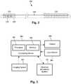
- Figure 2illustrates one embodiment of a lead 110 with electrodes 125 disposed at least partially about a circumference of the lead 110 along a distal end portion of the lead and terminals 135 disposed along a proximal end portion of the lead.
- the lead 110can be implanted near or within the desired portion of the body to be stimulated such as, for example, the brain, spinal cord, or other body organs or tissues.
- access to the desired position in the braincan be accomplished by drilling a hole in the patient's skull or cranium with a cranial drill (commonly referred to as a burr), and coagulating and incising the dura mater, or brain covering.
- a burrcommonly referred to as a burr
- the lead 110can be inserted into the cranium and brain tissue with the assistance of a stylet (not shown).
- the lead 110can be guided to the target location within the brain using, for example, a stereotactic frame and a microdrive motor system.
- the microdrive motor systemcan be fully or partially automatic.
- the microdrive motor systemmay be configured to perform one or more the following actions (alone or in combination): insert the lead 110, advance the lead 110, retract the lead 110, or rotate the lead 110.
- measurement devices coupled to the muscles or other tissues stimulated by the target neurons, or a unit responsive to the patient or cliniciancan be coupled to the implantable pulse generator or microdrive motor system.
- the measurement device, user, or cliniciancan indicate a response by the target muscles or other tissues to the stimulation or recording electrode(s) to further identify the target neurons and facilitate positioning of the stimulation electrode(s).
- a measurement devicecan be used to observe the muscle and indicate changes in tremor frequency or amplitude in response to stimulation of neurons.
- the patient or cliniciancan observe the muscle and provide feedback.
- the lead 110 for deep brain stimulationcan include stimulation electrodes, recording electrodes, or both.
- the lead 110is rotatable so that the stimulation electrodes can be aligned with the target neurons after the neurons have been located using the recording electrodes.
- Stimulation electrodesmay be disposed on the circumference of the lead 110 to stimulate the target neurons. Stimulation electrodes may be ring-shaped so that current projects from each electrode equally in every direction from the position of the electrode along a length of the lead 110. In the embodiment of Figure 2 , two of the electrodes 120 are ring electrodes 120. Ring electrodes typically do not enable stimulus current to be directed from only a limited angular range around of the lead. Segmented electrodes 130, however, can be used to direct stimulus current to a selected angular range around the lead.
- segmented electrodesWhen segmented electrodes are used in conjunction with an implantable pulse generator that delivers constant current stimulus, current steering can be achieved to more precisely deliver the stimulus to a position around an axis of the lead (i.e., radial positioning around the axis of the lead). To achieve current steering, segmented electrodes can be utilized in addition to, or as an alternative to, ring electrodes.
- the lead 100includes a lead body 110, terminals 135, and one or more ring electrodes 120 and one or more sets of segmented electrodes 130 (or any other combination of electrodes).
- the lead body 110can be formed of a biocompatible, nonconducting material such as, for example, a polymeric material. Suitable polymeric materials include, but are not limited to, silicone, polyurethane, polyurea, polyurethane-urea, polyethylene, or the like.
- the lead 100may be in contact with body tissue for extended periods of time.
- the lead 100has a cross-sectional diameter of no more than 1.5 mm and may be in the range of 0.5 to 1.5 mm.
- the lead 100has a length of at least 10 cm and the length of the lead 100 may be in the range of 10 to 70 cm.
- the electrodes 125can be made using a metal, alloy, conductive oxide, or any other suitable conductive biocompatible material.
- suitable materialsinclude, but are not limited to, platinum, platinum iridium alloy, iridium, titanium, tungsten, palladium, palladium rhodium, or the like.
- the electrodesare made of a material that is biocompatible and does not substantially corrode under expected operating conditions in the operating environment for the expected duration of use.
- Each of the electrodescan either be used or unused (OFF).
- the electrodecan be used as an anode or cathode and carry anodic or cathodic current.
- an electrodemight be an anode for a period of time and a cathode for a period of time.
- Deep brain stimulation leadsmay include one or more sets of segmented electrodes. Segmented electrodes may provide for superior current steering than ring electrodes because target structures in deep brain stimulation are not typically symmetric about the axis of the distal electrode array. Instead, a target may be located on one side of a plane running through the axis of the lead.
- RSEAradially segmented electrode array
- current steeringcan be performed not only along a length of the lead but also around a circumference of the lead. This provides precise three-dimensional targeting and delivery of the current stimulus to neural target tissue, while potentially avoiding stimulation of other tissue. Examples of leads with segmented electrodes include U.S. Patent Application Publications Nos.
- 2010/02682982011/0005069 ; 2011/0130803 ; 2011/0130816 ; 2011/0130817 ; 2011/0130818 ; 2011/0078900 ; 2011/0238129 ; 2012/0016378 ; 2012/0046710 ; 2012/0071949 ; 2012/0165911 ; 2012/197375 ; 2012/0203316 ; 2012/0203320 ; 2012/0203321 .
- An electrical stimulation leadcan be implanted in the body of a patient (for example, in the brain or spinal cord of the patient) and used to stimulate surrounding tissue. It is useful to estimate the effective region of stimulation (often called a volume of activation (VOA) or stimulation field model (SFM)) given the position of the lead and its electrodes in the patient's body and the stimulation parameters used to generate the stimulation.
- VOAvolume of activation
- SFMstimulation field model
- Any suitable method for determining the VOA and for graphically displaying the VOA relative to patient anatomycan be used including those described in, for example, U.S. Patents Nos. 8,326,433 ; 8,675,945 ; 8,831,731 ; 8,849,632 ; and 8.958,615 ; U.S. Patent Application Publications Nos.
- the term "estimated stimulation region"can refer to a VOA; a SFM; an estimate of an electric field, potential field, activating function field, Hermitian of an activating function, or any combination thereof or the like.
- a VOAis determined based on a set of stimulation parameters input into the system.
- the VOAcan then be modified by the user by modifying the stimulation parameters and determining the new VOA from the modified stimulation parameters. This allows the user to tailor the stimulation volume.
- the present systems or methodsallow the user to define the volume of tissue that is desired for stimulation and then the systems or methods determine a set of stimulation parameters based on that volume.
- the userselects the volume directly.
- the userselects the volume indirectly by indicating one or more stimulation effects to achieve or stimulation side effects to avoid.
- the user or systemcan select a volume based on regions with synchronous neural activity.
- Figure 3illustrates one embodiment of a system for determining electrical stimulation parameters.
- the systemcan include a computing device 300 or any other similar device that includes a processor 302 and a memory 304, a display 306, an input device 308, and, optionally, the electrical stimulation system 312.
- the system 300may also optionally include one or more imaging systems 310.
- the computing device 300can be a computer, tablet, mobile device, or any other suitable device for processing information.
- the computing device 300can be local to the user or can include components that are non-local to the computer including one or both of the processor 302 or memory 304 (or portions thereof).
- the usermay operate a terminal that is connected to a non-local computing device.
- the memorycan be non-local to the user.
- the computing device 300can utilize any suitable processor 302 including one or more hardware processors that may be local to the user or non-local to the user or other components of the computing device.
- the processor 302is configured to execute instructions provided to the processor, as described below.
- Any suitable memory 304can be used for the computing device 302.
- the memory 304illustrates a type of computer-readable media, namely computer-readable storage media.
- Computer-readable storage mediamay include, but is not limited to, nonvolatile, non-transitory, removable, and non-removable media implemented in any method or technology for storage of information, such as computer readable instructions, data structures, program modules, or other data. Examples of computer-readable storage media include RAM, ROM, EEPROM, flash memory, or other memory technology, CD-ROM, digital versatile disks (“DVD”) or other optical storage, magnetic cassettes, magnetic tape, magnetic disk storage or other magnetic storage devices, or any other medium which can be used to store the desired information and which can be accessed by a computing device.
- Communication methodsprovide another type of computer readable media; namely communication media.
- Communication mediatypically embodies computer-readable instructions, data structures, program modules, or other data in a modulated data signal such as a carrier wave, data signal, or other transport mechanism and include any information delivery media.
- modulated data signaland “carrier-wave signal” includes a signal that has one or more of its characteristics set or changed in such a manner as to encode information, instructions, data, and the like, in the signal.
- communication mediaincludes wired media such as twisted pair, coaxial cable, fiber optics, wave guides, and other wired media and wireless media such as acoustic, RF, infrared, and other wireless media.
- the display 306can be any suitable display device, such as a monitor, screen, display, or the like, and can include a printer.
- the input device 308can be, for example, a keyboard, mouse, touch screen, track ball, joystick, voice recognition system, or any combination thereof, or the like.
- One or more imaging systems 310can be used including, but not limited to, MRI, CT, ultrasound, or other imaging systems.
- the imaging system 310may communicate through a wired or wireless connection with the computing device 300 or, alternatively or additionally, a user can provide images from the imaging system 310 using a computer-readable medium or by some other mechanism.
- the electrical stimulation system 312can include, for example, any of the components illustrated in Figure 1 .
- the electrical stimulation system 312may communicate with the computing device 300 through a wired or wireless connection or, alternatively or additionally, a user can provide information between the electrical stimulation system 312 and the computing device 300 using a computer-readable medium or by some other mechanism.
- the computing device 300may include part of the electrical stimulation system, such as, for example, the IPG, CP, RC, ETS, or any combination thereof.
- Systems referenced hereintypically include memory and typically include methods for communication with other devices including mobile devices.
- Methods of communicationcan include both wired and wireless (e.g., RF, optical, or infrared) communications methods and such methods provide another type of computer readable media; namely communication media.
- Wired communicationcan include communication over a twisted pair, coaxial cable, fiber optics, wave guides, or the like, or any combination thereof.
- Wireless communicationcan include RF, infrared, acoustic, near field communication, BluetoothTM, or the like, or any combination thereof.
- Stimulationis one type of neuromodulation.
- Types of neuromodulationcan include, for example, stimulation (application of a stimulating field or drug), activation (actuating neurological tissue), depression (reducing the likelihood of activation of the neurological tissue), silencing (preventing the activation of the neurological tissue), or other forms of neuromodulation.
- stimulationis referred to in the embodiments below, it will be recognized that any other type of neuromodulation can be substituted for stimulation unless indicated otherwise.
- multiple forms of neuromodulation as described previouslymay be used in various combinations in the methods and systems described herein, with varying temporal order or relation, on the same target or targets.
- the interventioncan be accomplished using electrical stimulation, optical stimulation, drug stimulation, or the like or any combination thereof.
- the one or more targetsmay be selected with respect to the desired type of intervention, for example, one or more targets can be selected for activation, one or more targets for depression, and one or more targets for silencing, or any combination thereof. When multiple targets are identified, the targets may be selected for the same type of intervention or different targets may be selected for different types of intervention.
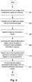
- FIG. 4is a flowchart illustrating one method for determining a set of stimulation parameters based on a user-selected stimulation volume.
- the imagecan be any suitable image such as a MRI, CT, ultrasound, or other image.
- At least one imagepreferably also includes an implanted electrical stimulation lead within the image so that the position, and, preferably, the orientation, of the lead relative to the patient tissue can be identified.
- more than one imagecan be received.
- a MRI image of an anatomical or physiological regionsuch as the brain, spinal cord, or other organ or tissue, or a portion thereof, can be obtained to show soft tissue portions of the region.
- a CT or MRI scancan also be obtained for the anatomical or physiological region with the electrical stimulation lead implanted to identify the position and orientation of the lead.
- the two or more imagesmay be registered with each other.
- an imageis not used, but the user or system estimates the position or orientation of the lead within the patient. This estimation may be based on, for example, surgical results, a surgical plan, external observations, or the like. In at least some embodiments, the estimate is based on a proposed position of a lead in the patient. The lead may or may not have been actually implanted in the patient. In some embodiments, the system can be used to plan a surgical implantation of a lead by investigating different placements or orientations. In the remainder of the discussion regarding the embodiment of Figure 4 , reference will be made to at least one image, but it will be understood that instead of an image an estimate of position or orientation or a proposed position or orientation of the lead can be used.
- the at least one image received in step 402is registered with an anatomical or physiological atlas, such as a neuroanatomical atlas, to associate anatomical or physiological structures from the atlas with the at least one image.
- the registered image(s)can be segmented into volume units that can, for example, each correspond to specific anatomical or physiological structures, or portions of anatomical or physiological structures, or correspond to any other division of the imaged region.
- the anatomical or physiological structures or segmented volumescan be labeled, numbered, or otherwise differentiated for the user on, for example, a display for review by the user.
- the useridentifies a desired stimulation region.
- the desired stimulation regioncan be identified within, or at least partially within, the imaged anatomical or physiological region.
- a usercan select the desired stimulation region by drawing or otherwise indicating the region on a display or other device.
- a usercan select the desired stimulation region by entering the name of one or more anatomical or physiological structures or by selecting one or more anatomical or physiological structures on a list. Any other suitable method for selecting a desired stimulation region can be used.
- the desired stimulation regionis compared to multiple predetermined estimated stimulation regions.
- the systemmay utilize any number of predetermined estimated stimulation regions, such as at least 10, 25, 50, 100, 200, or 500 predetermined estimated stimulation regions. These estimated stimulation regions are each associated with a set of stimulation parameters and can be predetermined using any method of calculation or estimation, including those disclosed in the references cited above, using the corresponding set of stimulation parameters. Additionally or alternatively, the desired stimulation region can be compared to one or more estimated stimulation regions that are calculated or estimated after selection of the desired stimulation region.
- the estimated stimulation regionsare estimated or determined with respect to the lead and then those estimated stimulation regions are registered to the anatomical or physiological atlas, images, or the desired stimulation region based on the position or orientation of the lead within the patient.
- the comparisons between the desired stimulation regions and the multiple predetermined estimated stimulation regionsinclude, for example, a quantitative determination of the fit of the identified stimulation region with one or more of the estimated stimulation regions.
- the systemcan reject an estimated stimulation region that fails to have a predetermined amount or percentage of overlap, or fails any other acceptance criteria, with respect to the identified stimulation region. In some embodiments, the system can reject an estimated stimulation region that fails to overlap with a predetermined amount or percentage of the identified stimulation region.
- the systemmay include other threshold determinations or, in at least some embodiments, the user may select one or more threshold requirements.
- the comparisonmay include reporting comparative information on a display or other device to the user.
- Such comparative informationcan include one or more of, for example, the amount or percentage coverage of the desired stimulation region by the estimated stimulation region, the amount or percentage of the desired stimulation region that is outside the estimated stimulation region, the amount or percentage of the estimated stimulation region that covers the desired stimulation region, the amount or percentage of the estimated stimulation region that is outside the desired stimulation region, other anatomical or physiological structures that may be stimulated by the estimated stimulation region, or the like.
- the desired stimulation region and the estimated stimulation regioncan be displayed to illustrate the overlap between the two.
- the systemmay only report comparative information on one or more, but less than all, of the estimated stimulation regions or display only one or more, but less than all, of the estimated stimulation regions. The selection of which estimated stimulation regions to include in the report or display may be by the best fit or other criteria that the system or user determines.
- one of the predetermined estimated stimulation regionsis selected based on the comparisons.
- one of the predetermined estimated stimulation regionsis selected by a user, preferably based on comparative information provided by the system to the user.
- one of the predetermined estimated stimulation regionsis selected by the system based on the comparisons.
- the usercan set selection criteria such as, for example, one or more thresholds for overlap, non-overlap, or the like or may provide rules or criteria for selecting among estimated stimulation regions that meet the thresholds, such as priority selection factor(s) or weighting of comparative information.
- the systemmay determine a "goodness-of-fit" based on the difference between the desired stimulation region and the estimated stimulation region and the system selects the estimated stimulation region with the best "goodness-of-fit".
- the systemmay allow the user to override the automatic selection by the system so that the user can select another estimated stimulation region.
- stimulation parameters for the selected estimated stimulation regioncan be provided to the user or directly to an implantable pulse generator, external trial stimulator, or other device that generates the electrical stimulation. These parameters can be provided by a wired connection, a wireless connection, or in any other suitable manner. In some embodiments, the system may allow a user to modify the stimulation parameters.
- FIG. 5is a flowchart illustrating one method for determining a set of stimulation parameters based on a user-selected stimulation effects or side effects.
- one or more functional mapscan be provided with each functional map identifying anatomical or physiological regions that produce one or more stimulation effects or stimulation side effects (collectively, "clinical effects") when electrically stimulated.
- One example of a method for forming a functional mapincludes registering patient images (for example, MRI images) into a common atlas space. Based on this registration, the therapeutic and side effects of various stimulation parameters applied to the patients can be associated with anatomical or physiological structures or other volume units in the common atlas space.
- the individual anatomical or physiological structures or other volume units into which the atlas space is dividedcan be referred to as "voxels".
- an estimated stimulation regioncan be calculated or estimated. Stimulation effects or side effects that are identified by the user or patient when stimulated using the set of stimulation parameters can then be associated with the voxels in the estimated stimulation region.
- a scorecan be associated with any clinical effect associated with the voxel. The score may be based on any suitable rating scale (for example, the Unified Parkinson's Disease Rating Scale (UPDRS)).
- UPDSUnified Parkinson's Disease Rating Scale
- these mapped clinical effectscan be aggregated across patients (for example, at least 5, 10, 20, 25, 50, or 100 patients or more) to generate an estimation of the likelihood for achieving a certain clinical effect given activation of a voxel at a given location in the common atlas space.
- v)could be the estimated probability of at least a 2-point therapeutic improvement in rigidity (R) given activation of voxel v, where this estimated probability is derived directly from the number of patients for which voxel v was stimulated.
- v)0.75.
- One or more (or even all) of the voxels in the atlas spacecan be labeled with multiple probabilities of being associated with multiple clinical effects, including stimulation effects and stimulation side effects.
- the useridentifies at least one desired stimulation effect or undesired stimulation side effect.
- the usercan select from a list of stimulation effects or stimulation side effects.
- the usermay input an effect or side effect and the system may correlate the input with a list of effects or side effects.
- the systemidentifies a desired stimulation region using the one or more functional maps based on the at least one selected stimulation effect or simulation side effect. For example, a stimulation region for a tremor-dominant patient might be selected by choosing voxels with a high probability of tremor improvement above a certain probability threshold, with the most probable voxels for achieving that improvement automatically selected and labeled as part of the desired stimulation region.
- the user or systemcould combine numerous voxels with the desired clinical effects and exclude voxels with having a likelihood above a threshold likelihood (for example, at least 10, 20, 25, 50, or 75 percent) of side effects (in general or specifically selected side effects) to generate the desired stimulation region.
- the desired stimulation regionis compared to multiple estimated stimulation regions.
- the systemmay utilize any number of estimated stimulation regions, such as at least 10, 25, 50, 100, 200, or 500 estimated stimulation regions. These estimated stimulation regions are each associated with a set of stimulation parameters and can be determined using any method of calculation or estimation, including those disclosed in the references cited above, using the corresponding set of stimulation parameters.
- the desired stimulation regioncan be compared to one or more estimated stimulation regions that are calculated or estimated after selection of the desired stimulation region.
- the estimated stimulation regionscan be predetermined prior to the selection of the desire stimulation region or prior to any other step in this method.
- the estimated stimulation regionsare estimated or determined with respect to the lead and then those estimated stimulation regions are registered to the anatomical or physiological atlas, images, or the desired stimulation region based on the position or orientation of the lead within the patient.
- the comparisons between the desired stimulation regions and the multiple estimated stimulation regionsinclude, for example, a quantitative determination of the fit of the identified stimulation region with one or more of the estimated stimulation regions.
- the systemcan reject an estimated stimulation region that fails to have a predetermined amount or percentage of overlap with the identified stimulation region. In some embodiments, the system can reject an estimated stimulation region that fails to overlap with a predetermined amount or percentage of the identified stimulation region.
- the systemmay include other threshold determinations or, in at least some embodiments, the user may select one or more threshold requirements.
- the comparisonmay include reporting comparative information on a display or other device to the user.
- Such comparative informationcan include one or more of, for example, the amount or percentage coverage of the desired stimulation region by the estimated stimulation region, the amount or percentage of the desired stimulation region that is outside the estimated stimulation region, the amount or percentage of the estimated stimulation region that covers the desired stimulation region, the amount or percentage of the estimated stimulation region that is outside the desired stimulation region, other anatomical or physiological structures that may be stimulated by the estimated stimulation region, or the like.
- the desired stimulation region and the estimated stimulation regioncan be displayed to illustrate the overlap between the two.
- the systemmay only report comparative information on one or more, but less than all, of the estimated stimulation regions or display only one or more, but less than all, of the estimated stimulation regions. The selection of which estimated stimulation regions to include in the report or display may be by the best fit or other criteria that the system or user determines.
- one of the estimated stimulation regionsis selected based on the comparisons.
- one of the estimated stimulation regionsis selected by a user, preferably based on comparative information provided by the system to the user.
- one of the estimated stimulation regionsis selected by the system based on the comparisons.
- the usercan set selection criteria such as, for example, one or more thresholds for overlap, non-overlap, and the like and may provide rules or criteria for selecting among estimated stimulation regions that meet the thresholds, such as priority selection factor(s) or weighting of comparative information.
- the systemmay determine a "goodness-of-fit" based on the difference between the desired stimulation region and the estimated stimulation region and the system selects the estimated stimulation region with the best "goodness-of-fit".
- the systemmay allow the user to override the automatic selection by the system so that the user can select another estimated stimulation region.
- stimulation parameters for the selected estimated stimulation regionare provided to the user or directly to an implantable pulse generator, external trial stimulator, or other device that generates the electrical stimulation. These parameters can be provided by a wired connection, a wireless connection, or in any other suitable manner. In some embodiments, the system may allow a user to modify the stimulation parameters.
- Figure 6is a flowchart illustrating one method for determining a set of stimulation parameters based on a user- or system-selected stimulation region utilizing information regarding synchronous neural activity. It has been found that stimulating subpopulations of neurons that exhibit synchronous neural activity can be used to treat a disease or disorder associated with the synchronous neural activity.
- U.S. Patents Nos. 8,000,794 and 8,280,514 and U.S. Provisional Patent Applications Serial Nos. 62/053,414 ; 62/053, 427 ; 62/053,501 ; 62/053,509 ; and 62/053,589describe methods of performing such stimulation.
- the stimulation of different subpopulations of neuronscan eliminate or reduce the synchronous neural activity.
- the stimulationcan produce a coordinated reset of the neural subpopulations.
- one or more regions of synchronous neural activityare determined. For example, local field potentials (LFPs) could be measured to map a region of synchronous neural activity, such as pathological coupling of oscillations in different regions of the brain.
- LFPslocal field potentials
- the region of synchronous neural activitymay be estimated by observation of patient symptoms or using information from other patients.
- at least one image of an anatomical or physiological region of a patientis received.
- the imagecan be any suitable image such as a MRI, CT, ultrasound, or other image.
- At least one imagepreferably also includes an implanted electrical stimulation lead within the image so that the position of the lead relative to the patient tissue can be identified. In at least some embodiments, more than one image can be received.
- a MRI image of an anatomical or physiological regionsuch as the brain or spinal cord or other organ, can be obtained to show soft tissue portions of the region.
- a CT scancan also be obtained for the anatomical or physiological region with the electrical stimulation lead implanted to identify the position and orientation of the lead.
- the two or more imagesmay be registered with each other.
- the regions of synchronous neural activitycan then be registered to the at least one image of the patient.
- the at least one image of the patient of the regions of synchronous neural activitycan be registered to an anatomical or physiological atlas.
- step 604one of the anatomical or physiological regions, if there is more than one, determined in step 602 or a portion of the anatomical or physiological region is selected.
- the selectionmay be made by a user or can be automatically made by the system.
- the selected anatomical or physiological regionis divided into multiple subregions.
- the subregionsdo not overlap.
- the subregionsmay overlap by no more than a threshold percentage, such as, for example, 1, 5, 10, or 25% in volume.
- the identified subregionsare each compared to multiple estimated stimulation regions.
- the systemmay utilize any number of estimated stimulation regions, such as at least 10, 25, 50, 100, 200, or 500 estimated stimulation regions. These estimated stimulation regions are each associated with a set of stimulation parameters and can be using any method of calculation or estimation, including those disclosed in the references cited above, using the corresponding set of stimulation parameters.
- the desired stimulation regioncan be compared to one or more estimated stimulation regions that are calculated or estimated after selection of the subregions.
- the estimated stimulation regionscan be predetermined prior to the selection of the desire stimulation region or prior to any other step in this method.
- the estimated stimulation regionsare estimated or determined relative to the lead and then those estimated stimulation regions are registered to the anatomical or physiological region and the identified subregions based on the position and orientation of the lead within the patient.
- the comparisoninclude, for example, a quantitative determination of the fit of the subregions with each of the estimated stimulation regions.
- the systemcan reject an estimated stimulation region that fails to have a predetermined amount or percentage of overlap with the subregion. In some embodiments, the system can reject an estimated stimulation region that fail to overlap with a predetermined amount or percentage of the subregion.
- the comparisonmay include reporting comparative information on a display or other device to the user.
- Such comparative informationcan include one or more of, for example, the amount or percentage coverage of the subregion by the estimated stimulation region, the amount or percentage of the subregion that is outside the estimated stimulation region, the amount or percentage of the estimated stimulation region that covers the subregion, the amount or percentage of the estimated stimulation region that is outside the subregion, or the like.
- the subregion and the estimated stimulation regioncan be displayed to illustrate the overlap between the two.
- one of the estimated stimulation regionsis selected for each subregion based on the comparison.
- one of the estimated stimulation regionsis selected by a user, preferably based on comparative information on the display.
- one of the estimated stimulation regionsis selected by the system based on the comparisons.
- the usermay set selection criteria including thresholds for overlap, non-overlap, and the like and may provide rules or criteria for selecting among estimated stimulation regions that meet the thresholds, such as priority selection factor(s) or weighting of comparative information.
- the systemmay allow the user to override the automatic selection by the system so that the user can select another estimated stimulation region.
- the individuals estimated stimulation regions for the subregionsactivate non-overlapping (or only slightly overlapping by no more than a threshold percentage, for example, no more than 1, 5, 10, or 25%), synchronized neuronal populations. This can allow the user or system to generate a desynchronizing pattern of stimulation pulses, aimed at a coordinated reset of the synchronized neural activity.
- a threshold percentagefor example, no more than 1, 5, 10, or 25%
- stimulation parameters for the selected estimated stimulation region for each subregionare provided to the user or directly to an implantable pulse generator, external trial stimulator, or other device that generates the electrical stimulation. These parameters can be provided by a wired connection, a wireless connection, or in any other suitable manner.
- the systemcan include one or more of the methods described hereinabove with respect to Figures 4-6 in any combination.
- the methods, systems, and units described hereinmay be embodied in many different forms and should not be construed as limited to the embodiments set forth herein. Accordingly, the methods, systems, and units described herein may take the form of an entirely hardware embodiment, an entirely software embodiment or an embodiment combining software and hardware aspects.
- the methods described hereincan be performed using any type of processor or any combination of processors where each processor performs at least part of the process.
- the computer program instructionscan be stored on any suitable computer-readable medium including, but not limited to, RAM, ROM, EEPROM, flash memory or other memory technology, CD-ROM, digital versatile disks ("DVD”) or other optical storage, magnetic cassettes, magnetic tape, magnetic disk storage or other magnetic storage devices, or any other medium which can be used to store the desired information and which can be accessed by a computing device.
- RAMrandom access memory
- ROMread only memory
- EEPROMelectrically erasable programmable read-only memory
- flash memoryor other memory technology
- CD-ROMcompact discs
- DVDdigital versatile disks
- magnetic cassettesmagnetic tape
- magnetic disk storagemagnetic disk storage devices
Landscapes
- Health & Medical Sciences (AREA)
- Engineering & Computer Science (AREA)
- Public Health (AREA)
- General Health & Medical Sciences (AREA)
- Biomedical Technology (AREA)
- Life Sciences & Earth Sciences (AREA)
- Veterinary Medicine (AREA)
- Animal Behavior & Ethology (AREA)
- Nuclear Medicine, Radiotherapy & Molecular Imaging (AREA)
- Radiology & Medical Imaging (AREA)
- Neurology (AREA)
- Medical Informatics (AREA)
- Neurosurgery (AREA)
- Epidemiology (AREA)
- Primary Health Care (AREA)
- Biophysics (AREA)
- Human Computer Interaction (AREA)
- Physiology (AREA)
- Pathology (AREA)
- Child & Adolescent Psychology (AREA)
- Psychology (AREA)
- Physical Education & Sports Medicine (AREA)
- Data Mining & Analysis (AREA)
- Databases & Information Systems (AREA)
- Hospice & Palliative Care (AREA)
- Psychiatry (AREA)
- Developmental Disabilities (AREA)
- General Business, Economics & Management (AREA)
- Business, Economics & Management (AREA)
- Cardiology (AREA)
- Heart & Thoracic Surgery (AREA)
- Orthopedic Medicine & Surgery (AREA)
- Pain & Pain Management (AREA)
- Electrotherapy Devices (AREA)
Description
- The present invention is directed to the area of implantable electrical stimulation systems. The present invention is also directed to systems selecting stimulation parameters based on desired stimulation effects or undesired stimulation side effects.
- Implantable electrical stimulation systems have proven therapeutic in a variety of diseases and disorders. For example, spinal cord stimulation systems have been used as a therapeutic modality for the treatment of chronic pain syndromes. Peripheral nerve stimulation has been used to treat chronic pain syndrome and incontinence, with a number of other applications under investigation. Functional electrical stimulation systems have been applied to restore some functionality to paralyzed extremities in spinal cord injury patients. Stimulation of the brain, such as deep brain stimulation, can be used to treat a variety of diseases or disorders.
- Stimulators have been developed to provide therapy for a variety of treatments. A stimulator can include a control module (with a pulse generator), one or more leads, and an array of stimulator electrodes on each lead. The stimulator electrodes are in contact with or near the nerves, muscles, or other tissue to be stimulated. The pulse generator in the control module generates electrical pulses that are delivered by the electrodes to body tissue.
U.S. Patent Application Publication No. 2013/0150922 discloses a computer-implemented method that includes storing a volume of tissue activation (VTA) data structure that is derived from analysis of a plurality of patients. Patient data is received for a given patient, the patient data representing an assessment of a patient condition. The VTA data structure is evaluated relative to the patient data to determine a target VTA for achieving a desired therapeutic effect for the given patient.U.S. Patent Application Publication No. 2012/0330622 discloses a computer-assisted method than can include defining a target VTA to achieve a desired therapeutic effect for an identical anatomical region. At least one parameter can be computed for an electrode design as a function of the defined target VTA. The computed at least one parameter can be stored in memory for the electrode design, which parameter can be utilized to construct an electrode.U.S. Patent Application Publication No. 2007/203538 describes system that allows a user to configure electrical stimulation therapy by selecting a structure of an anatomical region represented by an atlas. The atlas is a reference anatomical region of a reference anatomy that a clinician may use to identify structures of a patient anatomy that the clinician desires to stimulate during therapy. Structure selection may be efficient for the clinician, and allow the system to generate stimulation parameters that are adequate to treat the patient. The atlas may be most suitable for both axi-symmetric or three-dimensional leads having a complex electrode array geometry that allow greater flexibility in creating stimulation fields.- One embodiment is a system for identifying a set of stimulation parameters, the system includes a computer processor configured and arranged to perform the following actions: identifying a desired stimulation region; comparing the desired stimulation region with each of a plurality of predetermined stimulation regions, where each of the stimulation regions can be a defined region or a calculated estimate of a stimulation volume for a corresponding set of electrical stimulation parameters using an electrical stimulation lead; selecting one of the predetermined stimulation regions based on the comparing; and providing the corresponding set of electrical stimulation parameters for the selected one of the predetermined stimulation regions to a user or an electrical stimulation device.
- In at least some embodiments of the system, the actions further comprise: receiving at least one image of an anatomical or physiological region of a patient; and registering the at least one image with an anatomical or physiological atlas that identifies a plurality of different anatomical or physiological structures; where identifying a desired stimulation region comprises identifying a desired stimulation region using the at least one image. In at least some embodiments of the system, non-transitory computer-readable medium, or method described above, receiving at least one image includes receiving an image with the electrical stimulation lead implanted within the anatomical or physiological region. In at least some embodiments of the system, non-transitory computer-readable medium, or method described above, receiving at least one image includes receiving a first image of an anatomical or physiological region and a second image of the anatomical or physiological region with the electrical stimulation lead implanted within the anatomical or physiological region.
- A further embodiment is a system for identifying a set of stimulation parameters, the system includes a computer processor configured and arranged to perform the following acts: providing at least one functional map identifying anatomical or physiological volumes that, when stimulated, produce at least one stimulation effect or stimulation side effect in at least one patient along with an estimate of a likelihood that the anatomical or physiological volume will produce the at least one stimulation effect or stimulation side effect; identifying at least one desired stimulation effect or undesired stimulation side effect; using the at least one functional map, identifying a desired stimulation region that produces the at least one desired stimulation effect at a predetermined threshold likelihood or avoid the undesired stimulation side effect at a predetermined threshold likelihood; comparing the desired stimulation region with each of a plurality of stimulation regions, where each of the stimulation regions is a calculated estimate of a stimulation volume for a corresponding set of electrical stimulation parameters using an electrical stimulation lead; selecting one of the stimulation regions based on the comparing; and providing the corresponding set of electrical stimulation parameters for the selected one of the stimulation regions to a user or an electrical stimulation device.
- In at least some embodiments of the system, identifying the desired stimulation region includes selecting the desired stimulation region to produce the at least one desired stimulation effect and to avoid any stimulation side effects above a threshold likelihood. In at least some embodiments of the system, non-transitory computer-readable medium, or method described above, identifying the desired stimulation region includes selecting the desired stimulation region to produce the at least one desired stimulation effect and to avoid at least one identified stimulation side effect above a threshold likelihood. In at least some embodiments of the system, non-transitory computer-readable medium, or method described above, providing at least one functional map includes providing at least one functional map with scores associated with the anatomical or physiological volumes, each score being associated with at least one of the stimulation effects or stimulation side effects.
- A further embodiment is a system for identifying a set of stimulation parameters that includes a computer processor configured and arranged to perform the following acts: identifying a region of synchronous neural activity; dividing the region into a plurality of subregions; comparing the plurality of subregions with each of a plurality of estimated stimulation regions, where each of the estimated stimulation regions is a calculated estimate of a stimulation volume for a corresponding set of electrical stimulation parameters using an electrical stimulation lead; selecting, for each of the subregions, one of the estimated stimulation regions based on the comparisons such that each of the selected estimated stimulation regions overlaps with any of the other selected estimated stimulation regions by no more than a predetermined threshold; and providing the corresponding set of electrical stimulation parameters for each of the selected estimated stimulation regions to a user or an electrical stimulation device.
- In at least some embodiments of the system, identifying a region of synchronous neural activity includes receiving the region from a user. In at least some embodiments of the system, non-transitory computer-readable medium, or method described above, dividing the region includes dividing the regions into the plurality of subregions, wherein each subregion overlaps by no more than a predetermined threshold percentage with any other of the plurality of subregions. In at least some embodiments of the system, non-transitory computer-readable medium, or method described above, each of the selected estimated stimulation regions overlaps with any of the other selected estimated stimulation regions by no more than a predetermined threshold percentage. In at least some embodiments of the system, non-transitory computer-readable medium, or method described above, each of the selected estimated stimulation regions does not overlap with any of the other selected estimated stimulation regions.
- In at least some embodiments, any of the systems described above further includes the electrical stimulation device which includes the electrical stimulation lead. In at least some embodiments, any of the systems described above further includes an implantable pulse generator and providing the corresponding set of electrical stimulation parameters includes providing the corresponding set of electrical stimulation parameters to the implantable pulse generator.
- In at least some embodiments of any of the systems, selecting one of the estimated stimulation regions includes selecting the one of the estimated stimulation regions based on at least one selection criterion supplied by the user. In at least some embodiments of any of the systems, non-transitory computer-readable media, or methods described above, selecting one of the estimated stimulation regions includes selecting the one of the estimated stimulation regions based on at least one threshold criterion supplied by the user.
- Non-limiting and non-exhaustive embodiments of the present invention are described with reference to the following drawings. In the drawings, like reference numerals refer to like parts throughout the various figures unless otherwise specified.
- For a better understanding of the present invention, reference will be made to the following Detailed Description, which is to be read in association with the accompanying drawings, wherein:
FIG. 1 is a schematic view of one embodiment of an electrical stimulation system, according to the invention;FIG. 2 is a schematic side view of one embodiment of an electrical stimulation lead, according to the invention;FIG. 3 is a schematic block diagram of one embodiment of a system for determining stimulation parameters, according to the invention;FIG. 4 is a flowchart of one embodiment of a method of determining stimulation parameters, according to the invention;FIG. 5 is a flowchart of a second embodiment of a method of determining stimulation parameters, according to the invention; andFIG. 6 is a flowchart of a third embodiment of a method of determining stimulation parameters, according to the invention.- The invention is defined in claim 1. Further aspects and preferred embodiments are defined in the appended claims. Aspects, embodiments and examples of the present disclosure which do not fall under the scope of the appended claims do not form part of the invention and are merely provided for illustrative purposes. Furthermore, the methods presented in the present description are provided for illustrative purposes only and do not form part of the present invention. The present invention is directed to the area of implantable electrical stimulation systems and methods of making and using the systems. The present invention is also directed to methods of selecting stimulation parameters based on desired stimulation effects or undesired stimulation side effects.
- Suitable implantable electrical stimulation systems include, but are not limited to, a least one lead with one or more electrodes disposed on a distal end of the lead and one or more terminals disposed on one or more proximal ends of the lead. Leads include, for example, percutaneous leads and paddle leads. Examples of electrical stimulation systems with leads are found in, for example,
U.S. Patents Nos. 6,181,969 ;6,516,227 ;6,609,029 ;6,609,032 ;6,741,892 ;7,244,150 ;7,450,997 ;7,672,734 ;7,761,165 ;7,783,359 ;7,792,590 ;7,809,446 ;7,949,395 ;7,974,706 ;8,175,710 ;8,224,450 ;8,271,094 ;8,295,944 ;8,364,278 ;8,391,985 ; and8,688,235 ; andU.S. Patent Applications Publication Nos. 2007/0150036 ;2009/0187222 ;2009/0276021 ;2010/0076535 ;2010/0268298 ;2011/0005069 ;2011/0004267 ;2011/0078900 ;2011/0130817 ;2011/0130818 ;2011/0238129 ;2011/0313500 ;2012/0016378 ;2012/0046710 ;2012/0071949 ;2012/0165911 ;2012/0197375 ;2012/0203316 ;2012/0203320 ;2012/0203321 ;2012/0316615 ;2013/0105071 ; and2013/0197602 . In the discussion below, a percutaneous lead will be exemplified, but it will be understood that the methods and systems described herein are also applicable to paddle leads. - A percutaneous lead for electrical stimulation (for example, deep brain or spinal cord stimulation) includes stimulation electrodes that can be ring electrodes or segmented electrodes that extend only partially around the circumference of the lead or any combination thereof. The segmented electrodes can be provided in sets of electrodes, with each set having electrodes circumferentially distributed about the lead at a particular longitudinal position. For illustrative purposes, the leads are described herein relative to use for deep brain stimulation, but it will be understood that any of the leads can be used for applications other than deep brain stimulation, including spinal cord stimulation, peripheral nerve stimulation, or stimulation of other nerves and tissues.
- Turning to
Figure 1 , one embodiment of anelectrical stimulation system 10 includes one or more stimulation leads 12 and an implantable pulse generator (IPG) 14. Thesystem 10 can also include one or more of an external remote control (RC) 16, a clinician's programmer (CP) 18, an external trial stimulator (ETS) 20, or anexternal charger 22. - The
IPG 14 is physically connected, optionally via one or morelead extensions 24, to the stimulation lead(s) 12. Each lead carriesmultiple electrodes 26 arranged in an array. TheIPG 14 includes pulse generation circuitry that delivers electrical stimulation energy in the form of, for example, a pulsed electrical waveform (i.e., a temporal series of electrical pulses) to theelectrode array 26 in accordance with a set of stimulation parameters. The implantable pulse generator can be implanted into a patient's body, for example, below the patient's clavicle area or within the patient's buttocks or abdominal cavity. The implantable pulse generator can have eight stimulation channels which may be independently programmable to control the magnitude of the current or voltage stimulus from each channel. In some embodiments, the implantable pulse generator can have more or fewer than eight stimulation channels (e.g., 4-, 6-, 16-, 32-, or more stimulation channels). The implantable pulse generator can have one, two, three, four, or more connector ports, for receiving the terminals of the leads. - The
ETS 20 may also be physically connected, optionally via thepercutaneous lead extensions 28 andexternal cable 30, to the stimulation leads 12. TheETS 20, which has similar pulse generation circuitry as theIPG 14, also delivers electrical stimulation energy in the form of, for example, a pulsed electrical waveform to theelectrode array 26 in accordance with a set of stimulation parameters. One difference between theETS 20 and theIPG 14 is that theETS 20 is often a non-implantable device that is used on a trial basis after the neurostimulation leads 12 have been implanted and prior to implantation of theIPG 14, to test the responsiveness of the stimulation that is to be provided. Any functions described herein with respect to theIPG 14 can likewise be performed with respect to theETS 20. - The
RC 16 may be used to telemetrically communicate with or control theIPG 14 orETS 20 via a uni- or bi-directional wireless communications link 32. Once theIPG 14 and neurostimulation leads 12 are implanted, theRC 16 may be used to telemetrically communicate with or control theIPG 14 via a uni- or bi-directional communications link 34. Such communication or control allows theIPG 14 to be turned on or off and to be programmed with different stimulation parameter sets. TheIPG 14 may also be operated to modify the programmed stimulation parameters to actively control the characteristics of the electrical stimulation energy output by theIPG 14. TheCP 18 allows a user, such as a clinician, the ability to program stimulation parameters for theIPG 14 andETS 20 in the operating room and in follow-up sessions. - The
CP 18 may perform this function by indirectly communicating with theIPG 14 orETS 20, through theRC 16, via a wired or wireless communications link 36. Alternatively, theCP 18 may directly communicate with theIPG 14 orETS 20 via a wired or wireless communications link (not shown). The stimulation parameters provided by theCP 18 are also used to program theRC 16, so that the stimulation parameters can be subsequently modified by operation of theRC 16 in a stand-alone mode (i.e., without the assistance of the CP 18). - For purposes of brevity, the details of the
RC 16,CP 18,ETS 20, andexternal charger 22 will not be further described herein. Details of exemplary embodiments of these devices are disclosed inU.S. Pat. No. 6,895,280 . Other examples of electrical stimulation systems can be found atU.S. Patents Nos. 6,181,969 ;6,516,227 ;6,609,029 ;6,609,032 ;6,741,892 ;7,949,395 ;7,244,150 ;7,672,734 ; and7,761,165 ;7,974,706 ;8,175,710 ;8,224,450 ; and8,364,278 ; andU.S. Patent Application Publication No. 2007/0150036 . Figure 2 illustrates one embodiment of a lead 110 withelectrodes 125 disposed at least partially about a circumference of thelead 110 along a distal end portion of the lead andterminals 135 disposed along a proximal end portion of the lead.
Thelead 110 can be implanted near or within the desired portion of the body to be stimulated such as, for example, the brain, spinal cord, or other body organs or tissues. In one example of operation for deep brain stimulation, access to the desired position in the brain can be accomplished by drilling a hole in the patient's skull or cranium with a cranial drill (commonly referred to as a burr), and coagulating and incising the dura mater, or brain covering. Thelead 110 can be inserted into the cranium and brain tissue with the assistance of a stylet (not shown). Thelead 110 can be guided to the target location within the brain using, for example, a stereotactic frame and a microdrive motor system. In some embodiments, the microdrive motor system can be fully or partially automatic. The microdrive motor system may be configured to perform one or more the following actions (alone or in combination): insert thelead 110, advance thelead 110, retract thelead 110, or rotate thelead 110.- In some embodiments, measurement devices coupled to the muscles or other tissues stimulated by the target neurons, or a unit responsive to the patient or clinician, can be coupled to the implantable pulse generator or microdrive motor system. The measurement device, user, or clinician can indicate a response by the target muscles or other tissues to the stimulation or recording electrode(s) to further identify the target neurons and facilitate positioning of the stimulation electrode(s). For example, if the target neurons are directed to a muscle experiencing tremors, a measurement device can be used to observe the muscle and indicate changes in tremor frequency or amplitude in response to stimulation of neurons. Alternatively, the patient or clinician can observe the muscle and provide feedback.
- The
lead 110 for deep brain stimulation can include stimulation electrodes, recording electrodes, or both. In at least some embodiments, thelead 110 is rotatable so that the stimulation electrodes can be aligned with the target neurons after the neurons have been located using the recording electrodes. - Stimulation electrodes may be disposed on the circumference of the
lead 110 to stimulate the target neurons. Stimulation electrodes may be ring-shaped so that current projects from each electrode equally in every direction from the position of the electrode along a length of thelead 110. In the embodiment ofFigure 2 , two of theelectrodes 120 arering electrodes 120. Ring electrodes typically do not enable stimulus current to be directed from only a limited angular range around of the lead.Segmented electrodes 130, however, can be used to direct stimulus current to a selected angular range around the lead. When segmented electrodes are used in conjunction with an implantable pulse generator that delivers constant current stimulus, current steering can be achieved to more precisely deliver the stimulus to a position around an axis of the lead (i.e., radial positioning around the axis of the lead). To achieve current steering, segmented electrodes can be utilized in addition to, or as an alternative to, ring electrodes. - The
lead 100 includes alead body 110,terminals 135, and one ormore ring electrodes 120 and one or more sets of segmented electrodes 130 (or any other combination of electrodes). Thelead body 110 can be formed of a biocompatible, nonconducting material such as, for example, a polymeric material. Suitable polymeric materials include, but are not limited to, silicone, polyurethane, polyurea, polyurethane-urea, polyethylene, or the like. Once implanted in the body, thelead 100 may be in contact with body tissue for extended periods of time. In at least some embodiments, thelead 100 has a cross-sectional diameter of no more than 1.5 mm and may be in the range of 0.5 to 1.5 mm. In at least some embodiments, thelead 100 has a length of at least 10 cm and the length of thelead 100 may be in the range of 10 to 70 cm. - The
electrodes 125 can be made using a metal, alloy, conductive oxide, or any other suitable conductive biocompatible material. Examples of suitable materials include, but are not limited to, platinum, platinum iridium alloy, iridium, titanium, tungsten, palladium, palladium rhodium, or the like. Preferably, the electrodes are made of a material that is biocompatible and does not substantially corrode under expected operating conditions in the operating environment for the expected duration of use. - Each of the electrodes can either be used or unused (OFF). When the electrode is used, the electrode can be used as an anode or cathode and carry anodic or cathodic current. In some instances, an electrode might be an anode for a period of time and a cathode for a period of time.
- Deep brain stimulation leads may include one or more sets of segmented electrodes. Segmented electrodes may provide for superior current steering than ring electrodes because target structures in deep brain stimulation are not typically symmetric about the axis of the distal electrode array. Instead, a target may be located on one side of a plane running through the axis of the lead. Through the use of a radially segmented electrode array ("RSEA"), current steering can be performed not only along a length of the lead but also around a circumference of the lead. This provides precise three-dimensional targeting and delivery of the current stimulus to neural target tissue, while potentially avoiding stimulation of other tissue. Examples of leads with segmented electrodes include
U.S. Patent Application Publications Nos. 2010/0268298 ;2011/0005069 ;2011/0130803 ;2011/0130816 ;2011/0130817 ;2011/0130818 ;2011/0078900 ;2011/0238129 ;2012/0016378 ;2012/0046710 ;2012/0071949 ;2012/0165911 ;2012/197375 ;2012/0203316 ;2012/0203320 ;2012/0203321 . - An electrical stimulation lead can be implanted in the body of a patient (for example, in the brain or spinal cord of the patient) and used to stimulate surrounding tissue. It is useful to estimate the effective region of stimulation (often called a volume of activation (VOA) or stimulation field model (SFM)) given the position of the lead and its electrodes in the patient's body and the stimulation parameters used to generate the stimulation. Any suitable method for determining the VOA and for graphically displaying the VOA relative to patient anatomy can be used including those described in, for example,
U.S. Patents Nos. 8,326,433 ;8,675,945 ;8,831,731 ;8,849,632 ; and8.958,615 ;U.S. Patent Application Publications Nos. 2009/0287272 ;2009/0287273 ;2012/0314924 ;2013/0116744 ;2014/0122379 ; and2015/0066111 ; andU.S. Provisional Patent Application Serial No. 62/030,655 - In conventional systems, a VOA is determined based on a set of stimulation parameters input into the system. The VOA can then be modified by the user by modifying the stimulation parameters and determining the new VOA from the modified stimulation parameters. This allows the user to tailor the stimulation volume.
- In contrast to these conventional systems which determine the VOA from user-selected stimulation parameters, in at least some embodiments, the present systems or methods allow the user to define the volume of tissue that is desired for stimulation and then the systems or methods determine a set of stimulation parameters based on that volume. There are a number of different methods for selecting a desired stimulation volume described below. In some embodiments, the user selects the volume directly. In other embodiments, the user selects the volume indirectly by indicating one or more stimulation effects to achieve or stimulation side effects to avoid. Alternatively, the user or system can select a volume based on regions with synchronous neural activity.
Figure 3 illustrates one embodiment of a system for determining electrical stimulation parameters. The system can include acomputing device 300 or any other similar device that includes aprocessor 302 and amemory 304, adisplay 306, aninput device 308, and, optionally, theelectrical stimulation system 312. Thesystem 300 may also optionally include one ormore imaging systems 310.- The
computing device 300 can be a computer, tablet, mobile device, or any other suitable device for processing information. Thecomputing device 300 can be local to the user or can include components that are non-local to the computer including one or both of theprocessor 302 or memory 304 (or portions thereof). For example, in some embodiments, the user may operate a terminal that is connected to a non-local computing device. In other embodiments, the memory can be non-local to the user. - The
computing device 300 can utilize anysuitable processor 302 including one or more hardware processors that may be local to the user or non-local to the user or other components of the computing device. Theprocessor 302 is configured to execute instructions provided to the processor, as described below. - Any
suitable memory 304 can be used for thecomputing device 302. Thememory 304 illustrates a type of computer-readable media, namely computer-readable storage media. Computer-readable storage media may include, but is not limited to, nonvolatile, non-transitory, removable, and non-removable media implemented in any method or technology for storage of information, such as computer readable instructions, data structures, program modules, or other data. Examples of computer-readable storage media include RAM, ROM, EEPROM, flash memory, or other memory technology, CD-ROM, digital versatile disks ("DVD") or other optical storage, magnetic cassettes, magnetic tape, magnetic disk storage or other magnetic storage devices, or any other medium which can be used to store the desired information and which can be accessed by a computing device. - Communication methods provide another type of computer readable media; namely communication media. Communication media typically embodies computer-readable instructions, data structures, program modules, or other data in a modulated data signal such as a carrier wave, data signal, or other transport mechanism and include any information delivery media. The terms "modulated data signal," and "carrier-wave signal" includes a signal that has one or more of its characteristics set or changed in such a manner as to encode information, instructions, data, and the like, in the signal. By way of example, communication media includes wired media such as twisted pair, coaxial cable, fiber optics, wave guides, and other wired media and wireless media such as acoustic, RF, infrared, and other wireless media.
- The
display 306 can be any suitable display device, such as a monitor, screen, display, or the like, and can include a printer. Theinput device 308 can be, for example, a keyboard, mouse, touch screen, track ball, joystick, voice recognition system, or any combination thereof, or the like. - One or
more imaging systems 310 can be used including, but not limited to, MRI, CT, ultrasound, or other imaging systems. Theimaging system 310 may communicate through a wired or wireless connection with thecomputing device 300 or, alternatively or additionally, a user can provide images from theimaging system 310 using a computer-readable medium or by some other mechanism. - The
electrical stimulation system 312 can include, for example, any of the components illustrated inFigure 1 . Theelectrical stimulation system 312 may communicate with thecomputing device 300 through a wired or wireless connection or, alternatively or additionally, a user can provide information between theelectrical stimulation system 312 and thecomputing device 300 using a computer-readable medium or by some other mechanism. In some embodiments, thecomputing device 300 may include part of the electrical stimulation system, such as, for example, the IPG, CP, RC, ETS, or any combination thereof. - The methods and systems described herein may be embodied in many different forms and should not be construed as limited to the embodiments set forth herein. Accordingly, the methods and systems described herein may take the form of an entirely hardware embodiment, an entirely software embodiment or an embodiment combining software and hardware aspects. Systems referenced herein typically include memory and typically include methods for communication with other devices including mobile devices. Methods of communication can include both wired and wireless (e.g., RF, optical, or infrared) communications methods and such methods provide another type of computer readable media; namely communication media. Wired communication can include communication over a twisted pair, coaxial cable, fiber optics, wave guides, or the like, or any combination thereof. Wireless communication can include RF, infrared, acoustic, near field communication, Bluetooth™, or the like, or any combination thereof.
- Stimulation is one type of neuromodulation. Types of neuromodulation can include, for example, stimulation (application of a stimulating field or drug), activation (actuating neurological tissue), depression (reducing the likelihood of activation of the neurological tissue), silencing (preventing the activation of the neurological tissue), or other forms of neuromodulation. Although stimulation is referred to in the embodiments below, it will be recognized that any other type of neuromodulation can be substituted for stimulation unless indicated otherwise. Moreover, multiple forms of neuromodulation as described previously may be used in various combinations in the methods and systems described herein, with varying temporal order or relation, on the same target or targets. The intervention can be accomplished using electrical stimulation, optical stimulation, drug stimulation, or the like or any combination thereof. The one or more targets may be selected with respect to the desired type of intervention, for example, one or more targets can be selected for activation, one or more targets for depression, and one or more targets for silencing, or any combination thereof. When multiple targets are identified, the targets may be selected for the same type of intervention or different targets may be selected for different types of intervention.
Figure 4 is a flowchart illustrating one method for determining a set of stimulation parameters based on a user-selected stimulation volume. Instep 402, at least one image of an anatomical or physiological region of a patient is received. The image can be any suitable image such as a MRI, CT, ultrasound, or other image. At least one image preferably also includes an implanted electrical stimulation lead within the image so that the position, and, preferably, the orientation, of the lead relative to the patient tissue can be identified. In at least some embodiments, more than one image can be received. For example, in at least some embodiments, a MRI image of an anatomical or physiological region, such as the brain, spinal cord, or other organ or tissue, or a portion thereof, can be obtained to show soft tissue portions of the region. A CT or MRI scan can also be obtained for the anatomical or physiological region with the electrical stimulation lead implanted to identify the position and orientation of the lead. In at least some embodiments, the two or more images may be registered with each other.- In other embodiments, an image is not used, but the user or system estimates the position or orientation of the lead within the patient. This estimation may be based on, for example, surgical results, a surgical plan, external observations, or the like. In at least some embodiments, the estimate is based on a proposed position of a lead in the patient. The lead may or may not have been actually implanted in the patient. In some embodiments, the system can be used to plan a surgical implantation of a lead by investigating different placements or orientations. In the remainder of the discussion regarding the embodiment of
Figure 4 , reference will be made to at least one image, but it will be understood that instead of an image an estimate of position or orientation or a proposed position or orientation of the lead can be used. - In
step 404, the at least one image received instep 402 is registered with an anatomical or physiological atlas, such as a neuroanatomical atlas, to associate anatomical or physiological structures from the atlas with the at least one image. In at least some embodiments, the registered image(s) can be segmented into volume units that can, for example, each correspond to specific anatomical or physiological structures, or portions of anatomical or physiological structures, or correspond to any other division of the imaged region. In at least some embodiments, the anatomical or physiological structures or segmented volumes can be labeled, numbered, or otherwise differentiated for the user on, for example, a display for review by the user. - In
step 406, the user identifies a desired stimulation region. In embodiments in which at least one image is received the desired stimulation region can be identified within, or at least partially within, the imaged anatomical or physiological region. In at least some embodiments, a user can select the desired stimulation region by drawing or otherwise indicating the region on a display or other device. In at least some embodiments, a user can select the desired stimulation region by entering the name of one or more anatomical or physiological structures or by selecting one or more anatomical or physiological structures on a list. Any other suitable method for selecting a desired stimulation region can be used. - In
step 408, the desired stimulation region is compared to multiple predetermined estimated stimulation regions. The system may utilize any number of predetermined estimated stimulation regions, such as at least 10, 25, 50, 100, 200, or 500 predetermined estimated stimulation regions. These estimated stimulation regions are each associated with a set of stimulation parameters and can be predetermined using any method of calculation or estimation, including those disclosed in the references cited above, using the corresponding set of stimulation parameters. Additionally or alternatively, the desired stimulation region can be compared to one or more estimated stimulation regions that are calculated or estimated after selection of the desired stimulation region. - In at least some embodiments, the estimated stimulation regions are estimated or determined with respect to the lead and then those estimated stimulation regions are registered to the anatomical or physiological atlas, images, or the desired stimulation region based on the position or orientation of the lead within the patient. In at least some embodiments, the comparisons between the desired stimulation regions and the multiple predetermined estimated stimulation regions include, for example, a quantitative determination of the fit of the identified stimulation region with one or more of the estimated stimulation regions.
- In some embodiments, the system can reject an estimated stimulation region that fails to have a predetermined amount or percentage of overlap, or fails any other acceptance criteria, with respect to the identified stimulation region. In some embodiments, the system can reject an estimated stimulation region that fails to overlap with a predetermined amount or percentage of the identified stimulation region. The system may include other threshold determinations or, in at least some embodiments, the user may select one or more threshold requirements.
- The comparison may include reporting comparative information on a display or other device to the user. Such comparative information can include one or more of, for example, the amount or percentage coverage of the desired stimulation region by the estimated stimulation region, the amount or percentage of the desired stimulation region that is outside the estimated stimulation region, the amount or percentage of the estimated stimulation region that covers the desired stimulation region, the amount or percentage of the estimated stimulation region that is outside the desired stimulation region, other anatomical or physiological structures that may be stimulated by the estimated stimulation region, or the like. Alternatively or additionally, the desired stimulation region and the estimated stimulation region can be displayed to illustrate the overlap between the two. In some embodiments, the system may only report comparative information on one or more, but less than all, of the estimated stimulation regions or display only one or more, but less than all, of the estimated stimulation regions. The selection of which estimated stimulation regions to include in the report or display may be by the best fit or other criteria that the system or user determines.
- In
step 410, one of the predetermined estimated stimulation regions is selected based on the comparisons. In some embodiments, one of the predetermined estimated stimulation regions is selected by a user, preferably based on comparative information provided by the system to the user. In some embodiments, one of the predetermined estimated stimulation regions is selected by the system based on the comparisons. In at least some embodiments, the user can set selection criteria such as, for example, one or more thresholds for overlap, non-overlap, or the like or may provide rules or criteria for selecting among estimated stimulation regions that meet the thresholds, such as priority selection factor(s) or weighting of comparative information. As an example, the system may determine a "goodness-of-fit" based on the difference between the desired stimulation region and the estimated stimulation region and the system selects the estimated stimulation region with the best "goodness-of-fit". In at least some embodiments, the system may allow the user to override the automatic selection by the system so that the user can select another estimated stimulation region. - In
step 412, stimulation parameters for the selected estimated stimulation region can be provided to the user or directly to an implantable pulse generator, external trial stimulator, or other device that generates the electrical stimulation. These parameters can be provided by a wired connection, a wireless connection, or in any other suitable manner. In some embodiments, the system may allow a user to modify the stimulation parameters. Figure 5 is a flowchart illustrating one method for determining a set of stimulation parameters based on a user-selected stimulation effects or side effects. Instep 502, one or more functional maps can be provided with each functional map identifying anatomical or physiological regions that produce one or more stimulation effects or stimulation side effects (collectively, "clinical effects") when electrically stimulated.- One example of a method for forming a functional map includes registering patient images (for example, MRI images) into a common atlas space. Based on this registration, the therapeutic and side effects of various stimulation parameters applied to the patients can be associated with anatomical or physiological structures or other volume units in the common atlas space. The individual anatomical or physiological structures or other volume units into which the atlas space is divided can be referred to as "voxels". For each set of stimulation parameters, an estimated stimulation region can be calculated or estimated. Stimulation effects or side effects that are identified by the user or patient when stimulated using the set of stimulation parameters can then be associated with the voxels in the estimated stimulation region. In at least some embodiments, a score can be associated with any clinical effect associated with the voxel. The score may be based on any suitable rating scale (for example, the Unified Parkinson's Disease Rating Scale (UPDRS)).
- In at least some embodiments, these mapped clinical effects can be aggregated across patients (for example, at least 5, 10, 20, 25, 50, or 100 patients or more) to generate an estimation of the likelihood for achieving a certain clinical effect given activation of a voxel at a given location in the common atlas space. For example, p(R≥2|v) could be the estimated probability of at least a 2-point therapeutic improvement in rigidity (R) given activation of voxel v, where this estimated probability is derived directly from the number of patients for which voxel v was stimulated. As an example of this estimated probability, if a total of 40 patients had voxel v stimulated and 30/40 of them experienced a rigidity improvement of 2 points or greater, p(R≥2|v) =0.75. One or more (or even all) of the voxels in the atlas space can be labeled with multiple probabilities of being associated with multiple clinical effects, including stimulation effects and stimulation side effects.
- In
step 504, the user identifies at least one desired stimulation effect or undesired stimulation side effect. In at least some embodiments, the user can select from a list of stimulation effects or stimulation side effects. In other embodiments, the user may input an effect or side effect and the system may correlate the input with a list of effects or side effects. - In
step 506, the system identifies a desired stimulation region using the one or more functional maps based on the at least one selected stimulation effect or simulation side effect. For example, a stimulation region for a tremor-dominant patient might be selected by choosing voxels with a high probability of tremor improvement above a certain probability threshold, with the most probable voxels for achieving that improvement automatically selected and labeled as part of the desired stimulation region. In at least some embodiments, the user or system could combine numerous voxels with the desired clinical effects and exclude voxels with having a likelihood above a threshold likelihood (for example, at least 10, 20, 25, 50, or 75 percent) of side effects (in general or specifically selected side effects) to generate the desired stimulation region. - In
step 508, the desired stimulation region is compared to multiple estimated stimulation regions. The system may utilize any number of estimated stimulation regions, such as at least 10, 25, 50, 100, 200, or 500 estimated stimulation regions. These estimated stimulation regions are each associated with a set of stimulation parameters and can be determined using any method of calculation or estimation, including those disclosed in the references cited above, using the corresponding set of stimulation parameters. In at least some embodiments, the desired stimulation region can be compared to one or more estimated stimulation regions that are calculated or estimated after selection of the desired stimulation region. In at least some embodiments, the estimated stimulation regions can be predetermined prior to the selection of the desire stimulation region or prior to any other step in this method. - In at least some embodiments, the estimated stimulation regions are estimated or determined with respect to the lead and then those estimated stimulation regions are registered to the anatomical or physiological atlas, images, or the desired stimulation region based on the position or orientation of the lead within the patient. In at least some embodiments, the comparisons between the desired stimulation regions and the multiple estimated stimulation regions include, for example, a quantitative determination of the fit of the identified stimulation region with one or more of the estimated stimulation regions.
- In some embodiments, the system can reject an estimated stimulation region that fails to have a predetermined amount or percentage of overlap with the identified stimulation region. In some embodiments, the system can reject an estimated stimulation region that fails to overlap with a predetermined amount or percentage of the identified stimulation region. The system may include other threshold determinations or, in at least some embodiments, the user may select one or more threshold requirements.
- The comparison may include reporting comparative information on a display or other device to the user. Such comparative information can include one or more of, for example, the amount or percentage coverage of the desired stimulation region by the estimated stimulation region, the amount or percentage of the desired stimulation region that is outside the estimated stimulation region, the amount or percentage of the estimated stimulation region that covers the desired stimulation region, the amount or percentage of the estimated stimulation region that is outside the desired stimulation region, other anatomical or physiological structures that may be stimulated by the estimated stimulation region, or the like. Alternatively or additionally, the desired stimulation region and the estimated stimulation region can be displayed to illustrate the overlap between the two. In some embodiments, the system may only report comparative information on one or more, but less than all, of the estimated stimulation regions or display only one or more, but less than all, of the estimated stimulation regions. The selection of which estimated stimulation regions to include in the report or display may be by the best fit or other criteria that the system or user determines.
- In
step 510, one of the estimated stimulation regions is selected based on the comparisons. In some embodiments, one of the estimated stimulation regions is selected by a user, preferably based on comparative information provided by the system to the user. In some embodiments, one of the estimated stimulation regions is selected by the system based on the comparisons. In at least some embodiments, the user can set selection criteria such as, for example, one or more thresholds for overlap, non-overlap, and the like and may provide rules or criteria for selecting among estimated stimulation regions that meet the thresholds, such as priority selection factor(s) or weighting of comparative information. As an example, the system may determine a "goodness-of-fit" based on the difference between the desired stimulation region and the estimated stimulation region and the system selects the estimated stimulation region with the best "goodness-of-fit". In some of these embodiments, the system may allow the user to override the automatic selection by the system so that the user can select another estimated stimulation region. - In
step 512, stimulation parameters for the selected estimated stimulation region are provided to the user or directly to an implantable pulse generator, external trial stimulator, or other device that generates the electrical stimulation. These parameters can be provided by a wired connection, a wireless connection, or in any other suitable manner. In some embodiments, the system may allow a user to modify the stimulation parameters. Figure 6 is a flowchart illustrating one method for determining a set of stimulation parameters based on a user- or system-selected stimulation region utilizing information regarding synchronous neural activity. It has been found that stimulating subpopulations of neurons that exhibit synchronous neural activity can be used to treat a disease or disorder associated with the synchronous neural activity.U.S. Patents Nos. 8,000,794 and8,280,514 andU.S. Provisional Patent Applications Serial Nos. 62/053,414 62/053, 427 62/053,501 62/053,509 62/053,589 - In
step 602, one or more regions of synchronous neural activity are determined. For example, local field potentials (LFPs) could be measured to map a region of synchronous neural activity, such as pathological coupling of oscillations in different regions of the brain. In other embodiments, the region of synchronous neural activity may be estimated by observation of patient symptoms or using information from other patients. In at least some embodiments, at least one image of an anatomical or physiological region of a patient is received. The image can be any suitable image such as a MRI, CT, ultrasound, or other image. At least one image preferably also includes an implanted electrical stimulation lead within the image so that the position of the lead relative to the patient tissue can be identified. In at least some embodiments, more than one image can be received. For example, in one embodiment, a MRI image of an anatomical or physiological region, such as the brain or spinal cord or other organ, can be obtained to show soft tissue portions of the region. A CT scan can also be obtained for the anatomical or physiological region with the electrical stimulation lead implanted to identify the position and orientation of the lead. In at least some embodiments, the two or more images may be registered with each other. - In some embodiments, the regions of synchronous neural activity can then be registered to the at least one image of the patient. Alternatively or additionally, the at least one image of the patient of the regions of synchronous neural activity can be registered to an anatomical or physiological atlas.
- In
step 604, one of the anatomical or physiological regions, if there is more than one, determined instep 602 or a portion of the anatomical or physiological region is selected. The selection may be made by a user or can be automatically made by the system. - In
step 606, the selected anatomical or physiological region is divided into multiple subregions. In at least some embodiments, the subregions do not overlap. In other embodiments, the subregions may overlap by no more than a threshold percentage, such as, for example, 1, 5, 10, or 25% in volume. - In
step 608, the identified subregions are each compared to multiple estimated stimulation regions. The system may utilize any number of estimated stimulation regions, such as at least 10, 25, 50, 100, 200, or 500 estimated stimulation regions. These estimated stimulation regions are each associated with a set of stimulation parameters and can be using any method of calculation or estimation, including those disclosed in the references cited above, using the corresponding set of stimulation parameters. In at least some embodiments, the desired stimulation region can be compared to one or more estimated stimulation regions that are calculated or estimated after selection of the subregions. In at least some embodiments, the estimated stimulation regions can be predetermined prior to the selection of the desire stimulation region or prior to any other step in this method. - In at least some embodiments, the estimated stimulation regions are estimated or determined relative to the lead and then those estimated stimulation regions are registered to the anatomical or physiological region and the identified subregions based on the position and orientation of the lead within the patient. The comparison include, for example, a quantitative determination of the fit of the subregions with each of the estimated stimulation regions. In some embodiments, the system can reject an estimated stimulation region that fails to have a predetermined amount or percentage of overlap with the subregion. In some embodiments, the system can reject an estimated stimulation region that fail to overlap with a predetermined amount or percentage of the subregion.
- The comparison may include reporting comparative information on a display or other device to the user. Such comparative information can include one or more of, for example, the amount or percentage coverage of the subregion by the estimated stimulation region, the amount or percentage of the subregion that is outside the estimated stimulation region, the amount or percentage of the estimated stimulation region that covers the subregion, the amount or percentage of the estimated stimulation region that is outside the subregion, or the like. Alternatively or additionally, the subregion and the estimated stimulation region can be displayed to illustrate the overlap between the two.
- In
step 610, one of the estimated stimulation regions is selected for each subregion based on the comparison. In some embodiments, one of the estimated stimulation regions is selected by a user, preferably based on comparative information on the display. In some embodiments, one of the estimated stimulation regions is selected by the system based on the comparisons. The user may set selection criteria including thresholds for overlap, non-overlap, and the like and may provide rules or criteria for selecting among estimated stimulation regions that meet the thresholds, such as priority selection factor(s) or weighting of comparative information. In some of these embodiments, the system may allow the user to override the automatic selection by the system so that the user can select another estimated stimulation region. In at least some embodiments, the individuals estimated stimulation regions for the subregions activate non-overlapping (or only slightly overlapping by no more than a threshold percentage, for example, no more than 1, 5, 10, or 25%), synchronized neuronal populations. This can allow the user or system to generate a desynchronizing pattern of stimulation pulses, aimed at a coordinated reset of the synchronized neural activity. - In
step 612, stimulation parameters for the selected estimated stimulation region for each subregion are provided to the user or directly to an implantable pulse generator, external trial stimulator, or other device that generates the electrical stimulation. These parameters can be provided by a wired connection, a wireless connection, or in any other suitable manner. - It will be understood that the system can include one or more of the methods described hereinabove with respect to
Figures 4-6 in any combination. The methods, systems, and units described herein may be embodied in many different forms and should not be construed as limited to the embodiments set forth herein. Accordingly, the methods, systems, and units described herein may take the form of an entirely hardware embodiment, an entirely software embodiment or an embodiment combining software and hardware aspects. The methods described herein can be performed using any type of processor or any combination of processors where each processor performs at least part of the process. - It will be understood that each block of the flowchart illustrations, and combinations of blocks in the flowchart illustrations and methods disclosed herein, can be implemented by computer program instructions. These program instructions may be provided to a processor to produce a machine, such that the instructions, which execute on the processor, create means for implementing the actions specified in the flowchart block or blocks disclosed herein. The computer program instructions may be executed by a processor to cause a series of operational steps to be performed by the processor to produce a computer implemented process. The computer program instructions may also cause at least some of the operational steps to be performed in parallel. Moreover, some of the steps may also be performed across more than one processor, such as might arise in a multi-processor computer system. In addition, one or more processes may also be performed concurrently with other processes, or even in a different sequence than illustrated without departing from the scope or spirit of the invention.
- The computer program instructions can be stored on any suitable computer-readable medium including, but not limited to, RAM, ROM, EEPROM, flash memory or other memory technology, CD-ROM, digital versatile disks ("DVD") or other optical storage, magnetic cassettes, magnetic tape, magnetic disk storage or other magnetic storage devices, or any other medium which can be used to store the desired information and which can be accessed by a computing device.
- The above specification provides a description of the structure, manufacture, and use of the invention. Since many embodiments of the invention can be made without departing from the scope of the invention, the invention also resides in the claims hereinafter appended.
Claims (8)
- A system for identifying a set of stimulation parameters, the system comprising:
a computer processor (302) configured and arranged to perform the following acts:providing at least one functional map identifying anatomical or physiological volumes that, when stimulated, produce at least one stimulation effect or stimulation side effect in at least one patient along with an estimate of a likelihood that the anatomical or physiological volume will produce the at least one stimulation effect or stimulation side effect;identifying at least one desired stimulation effect or undesired stimulation side effect;using the at least one functional map, identifying a desired stimulation region that produces the at least one desired stimulation effect at a predetermined threshold likelihood or avoids the undesired stimulation side effect at a predetermined threshold likelihood;comparing the desired stimulation region with each of a plurality of estimated stimulation regions, wherein each of the estimated stimulation regions is a calculated estimate of a stimulation volume for a corresponding set of electrical stimulation parameters using an electrical stimulation lead;selecting one of the estimated stimulation regions based on the comparing; andproviding the corresponding set of electrical stimulation parameters for the selected one of the estimated stimulation regions to a user or an electrical stimulation device. - The system of claim 1, wherein identifying the desired stimulation region comprises selecting the desired stimulation region to produce the at least one desired stimulation effect and to avoid any stimulation side effects above a threshold likelihood.
- The system of claim 1, wherein identifying the desired stimulation region comprises selecting the desired stimulation region to produce the at least one desired stimulation effect and to avoid at least one identified stimulation side effect above a threshold likelihood.
- The system of any one of claims 4-6, wherein providing at least one functional map comprises providing at least one functional map with scores associated with the anatomical or physiological volumes, each score being associated with at least one of the stimulation effects or stimulation side effects.
- The system of any one of claims 1-4, further comprising the electrical stimulation device which comprises the electrical stimulation lead.
- The system of claim 5, wherein the system further comprises an implantable pulse generator, wherein providing the corresponding set of electrical stimulation parameters comprises providing the corresponding set of electrical stimulation parameters to the implantable pulse generator.
- The system of any one of claims 1-6, wherein selecting one of the estimated stimulation regions comprises selecting the one of the estimated stimulation regions based on at least one selection criterion which is supplied by the user.
- The system of any one of claims 1-7, wherein selecting one of the estimated stimulation regions comprises selecting the one of the estimated stimulation regions based on at least one threshold criterion supplied by the user.
Applications Claiming Priority (2)
| Application Number | Priority Date | Filing Date | Title |
|---|---|---|---|
| US201562186184P | 2015-06-29 | 2015-06-29 | |
| PCT/US2016/039641WO2017003946A1 (en) | 2015-06-29 | 2016-06-27 | Systems and methods for selecting stimulation parameters based on stimulation target region, effects, or side effects |
Publications (2)
| Publication Number | Publication Date |
|---|---|
| EP3280490A1 EP3280490A1 (en) | 2018-02-14 |
| EP3280490B1true EP3280490B1 (en) | 2021-09-01 |
Family
ID=56409207
Family Applications (1)
| Application Number | Title | Priority Date | Filing Date |
|---|---|---|---|
| EP16738313.2AActiveEP3280490B1 (en) | 2015-06-29 | 2016-06-27 | Systems for selecting stimulation parameters based on stimulation target region, effects, or side effects |
Country Status (3)
| Country | Link |
|---|---|
| US (3) | US20160375248A1 (en) |
| EP (1) | EP3280490B1 (en) |
| WO (1) | WO2017003946A1 (en) |
Families Citing this family (24)
| Publication number | Priority date | Publication date | Assignee | Title |
|---|---|---|---|---|
| US9974959B2 (en) | 2014-10-07 | 2018-05-22 | Boston Scientific Neuromodulation Corporation | Systems, devices, and methods for electrical stimulation using feedback to adjust stimulation parameters |
| EP3458152B1 (en) | 2016-06-24 | 2021-04-21 | Boston Scientific Neuromodulation Corporation | Systems and methods for visual analytics of clinical effects |
| WO2018044881A1 (en) | 2016-09-02 | 2018-03-08 | Boston Scientific Neuromodulation Corporation | Systems and methods for visualizing and directing stimulation of neural elements |
| US10780282B2 (en) | 2016-09-20 | 2020-09-22 | Boston Scientific Neuromodulation Corporation | Systems and methods for steering electrical stimulation of patient tissue and determining stimulation parameters |
| ES2869184T3 (en) | 2016-10-14 | 2021-10-25 | Boston Scient Neuromodulation Corp | Systems to determine in closed loop the configuration of the stimulation parameters of an electrical stimulation system |
| JP6834005B2 (en) | 2017-01-03 | 2021-02-24 | ボストン サイエンティフィック ニューロモデュレイション コーポレイション | Systems and methods for selecting MRI-matched stimulus parameters |
| EP3519043B1 (en)* | 2017-01-10 | 2020-08-12 | Boston Scientific Neuromodulation Corporation | Systems and methods for creating stimulation programs based on user-defined areas or volumes |
| US10625082B2 (en) | 2017-03-15 | 2020-04-21 | Boston Scientific Neuromodulation Corporation | Visualization of deep brain stimulation efficacy |
| US11357986B2 (en) | 2017-04-03 | 2022-06-14 | Boston Scientific Neuromodulation Corporation | Systems and methods for estimating a volume of activation using a compressed database of threshold values |
| JP6932835B2 (en) | 2017-07-14 | 2021-09-08 | ボストン サイエンティフィック ニューロモデュレイション コーポレイション | Systems and methods for estimating the clinical effects of electrical stimulation |
| EP3634569A1 (en) | 2017-08-15 | 2020-04-15 | Boston Scientific Neuromodulation Corporation | Systems and methods for controlling electrical stimulation using multiple stimulation fields |
| CN111801046B (en)* | 2017-11-10 | 2023-11-07 | 勒维斯公司 | Efficacy and/or therapeutic parameter recommendation using individual patient data and therapeutic brain network map |
| EP3749411B1 (en) | 2018-02-09 | 2022-03-02 | Boston Scientific Neuromodulation Corporation | Systems for determining neuromodulation parameters |
| EP3784332B1 (en) | 2018-04-27 | 2023-04-26 | Boston Scientific Neuromodulation Corporation | Systems for visualizing and programming electrical stimulation |
| US11298553B2 (en) | 2018-04-27 | 2022-04-12 | Boston Scientific Neuromodulation Corporation | Multi-mode electrical stimulation systems and methods of making and using |
| WO2019210117A1 (en) | 2018-04-27 | 2019-10-31 | Boston Scientific Neuromodulation Corporation | Multiple mode neuromodulation responsive to patient information |
| WO2019210114A2 (en) | 2018-04-27 | 2019-10-31 | Boston Scientific Neuromodulation Corporation | Translation between cathodic and anodic neuromodulation parameter settings |
| US10905882B2 (en) | 2019-01-22 | 2021-02-02 | General Electric Company | Systems and methods for predicting optimal deep brain stimulation parameters |
| EP4022634A1 (en)* | 2019-08-27 | 2022-07-06 | Medtronic, Inc. | Method and apparatus for planning a procedure |
| JP7688170B2 (en) | 2021-02-25 | 2025-06-03 | ボストン サイエンティフィック ニューロモデュレイション コーポレイション | Method and system for deep brain stimulation of the nucleus basalis of meynert |
| US12403315B2 (en) | 2021-04-27 | 2025-09-02 | Boston Scientific Neuromodulation Corporation | Systems and methods for automated programming of electrical stimulation |
| US12403313B2 (en) | 2021-06-15 | 2025-09-02 | Boston Scientific Neuromodulation Corporation | Methods and systems for estimating neural activation by stimulation using a stimulation system |
| US20250069332A1 (en)* | 2023-08-24 | 2025-02-27 | Clearpoint Neuro, Inc. | Automatic neurosurgical target and entry point identification |
| WO2025090313A1 (en)* | 2023-10-24 | 2025-05-01 | Boston Scientific Neuromodulation Corporation | Use of brain anatomical features to optimize deep brain stimulation |
Family Cites Families (403)
| Publication number | Priority date | Publication date | Assignee | Title |
|---|---|---|---|---|
| US3999555A (en) | 1975-10-28 | 1976-12-28 | Medtronic, Inc. | Atrial pinch on lead and insertion tool |
| AR216293A1 (en) | 1976-12-02 | 1979-12-14 | Leon De Pedro F | SELF-FIXING TOOTH ELECTRODE AND A GRIPPER FOR ITS MANEUVERING |
| US4144889A (en) | 1977-05-31 | 1979-03-20 | Research Corporation | Cardiac electrodes for temporary pacing |
| US4378797A (en) | 1980-04-14 | 1983-04-05 | Thomas Jefferson University | Extravascular circulation of oxygenated synthetic nutrients to treat tissue hypoxic and ischemic disorders |
| US4445500A (en) | 1982-03-03 | 1984-05-01 | Thomas Jefferson University | Stroke treatment utilizing extravascular circulation of oxygenated synthetic nutrients to treat tissue hypoxic and ischemic disorders |
| US4341221A (en) | 1980-10-07 | 1982-07-27 | Medtronic, Inc. | Shielded recording electrode system |
| US4765341A (en) | 1981-06-22 | 1988-08-23 | Mieczyslaw Mirowski | Cardiac electrode with attachment fin |
| US5370675A (en) | 1992-08-12 | 1994-12-06 | Vidamed, Inc. | Medical probe device and method |
| US4735208B1 (en) | 1987-01-09 | 1995-07-04 | Ad Tech Medical Instr Corp | Subdural strip electrode for determining epileptogenic foci |
| US4841973A (en) | 1987-09-21 | 1989-06-27 | Stecker Harold D | Electrical stimulators |
| US5099846A (en) | 1988-12-23 | 1992-03-31 | Hardy Tyrone L | Method and apparatus for video presentation from a variety of scanner imaging sources |
| US6240308B1 (en) | 1988-12-23 | 2001-05-29 | Tyrone L. Hardy | Method and apparatus for archiving and displaying anatomico-physiological data in a normalized whole brain mapping and imaging system |
| US5067495A (en) | 1989-09-27 | 1991-11-26 | Brehm Richard L | Electro wave therapy |
| US5255693A (en) | 1989-11-02 | 1993-10-26 | Possis Medical, Inc. | Cardiac lead |
| US5222494A (en) | 1991-07-31 | 1993-06-29 | Cyberonics, Inc. | Implantable tissue stimulator output stabilization system |
| US5259387A (en) | 1991-09-09 | 1993-11-09 | Quinton Instrument Company | ECG muscle artifact filter system |
| US5304206A (en) | 1991-11-18 | 1994-04-19 | Cyberonics, Inc. | Activation techniques for implantable medical device |
| DE69325508T2 (en) | 1992-03-09 | 2000-01-27 | St. Georg's Hospital Medical School, London | NEUROGRAPHIC IMAGING METHOD AND DIFFUSION ANISTROPY |
| US5603318A (en) | 1992-04-21 | 1997-02-18 | University Of Utah Research Foundation | Apparatus and method for photogrammetric surgical localization |
| US5365996A (en) | 1992-06-10 | 1994-11-22 | Amei Technologies Inc. | Method and apparatus for making customized fixation devices |
| US6096756A (en) | 1992-09-21 | 2000-08-01 | Albert Einstein College Of Medicine Of Yeshiva University | Method of simultaneously enhancing analgesic potency and attenuating dependence liability caused by morphine and other bimodally-acting opioid agonists |
| GB9302335D0 (en) | 1993-02-05 | 1993-03-24 | Macdonald Alexander J R | Electrotherapeutic apparatus |
| US5361763A (en) | 1993-03-02 | 1994-11-08 | Wisconsin Alumni Research Foundation | Method for segmenting features in an image |
| US5344438A (en) | 1993-04-16 | 1994-09-06 | Medtronic, Inc. | Cuff electrode |
| US5601612A (en) | 1993-08-06 | 1997-02-11 | Heartstream, Inc. | Method for applying a multiphasic waveform |
| US5607454A (en) | 1993-08-06 | 1997-03-04 | Heartstream, Inc. | Electrotherapy method and apparatus |
| US6129685A (en) | 1994-02-09 | 2000-10-10 | The University Of Iowa Research Foundation | Stereotactic hypothalamic obesity probe |
| US5651767A (en) | 1994-05-06 | 1997-07-29 | Alfred F. Mann Foundation For Scientific Research | Replaceable catheter system for physiological sensors, stimulating electrodes and/or implantable fluid delivery systems |
| EP0928212B1 (en) | 1994-07-13 | 2002-10-02 | Fraunhofer-Gesellschaft zur Förderung der angewandten Forschung e.V. | Flexible artificial nerve plate |
| US6694163B1 (en) | 1994-10-27 | 2004-02-17 | Wake Forest University Health Sciences | Method and system for producing interactive, three-dimensional renderings of selected body organs having hollow lumens to enable simulated movement through the lumen |
| US5782762A (en) | 1994-10-27 | 1998-07-21 | Wake Forest University | Method and system for producing interactive, three-dimensional renderings of selected body organs having hollow lumens to enable simulated movement through the lumen |
| US5682468A (en) | 1995-01-23 | 1997-10-28 | Intergraph Corporation | OLE for design and modeling |
| US5868740A (en) | 1995-03-24 | 1999-02-09 | Board Of Regents-Univ Of Nebraska | Method for volumetric tissue ablation |
| US5565949A (en) | 1995-07-10 | 1996-10-15 | Kasha, Jr.; John R. | Visual field perimetry on a small computer screen |
| US5724985A (en) | 1995-08-02 | 1998-03-10 | Pacesetter, Inc. | User interface for an implantable medical device using an integrated digitizer display screen |
| US6944501B1 (en) | 2000-04-05 | 2005-09-13 | Neurospace, Inc. | Neurostimulator involving stimulation strategies and process for using it |
| US6463328B1 (en) | 1996-02-02 | 2002-10-08 | Michael Sasha John | Adaptive brain stimulation method and system |
| US6066163A (en) | 1996-02-02 | 2000-05-23 | John; Michael Sasha | Adaptive brain stimulation method and system |
| US5925070A (en) | 1996-04-04 | 1999-07-20 | Medtronic, Inc. | Techniques for adjusting the locus of excitation of electrically excitable tissue |
| US5713922A (en) | 1996-04-25 | 1998-02-03 | Medtronic, Inc. | Techniques for adjusting the locus of excitation of neural tissue in the spinal cord or brain |
| US5716377A (en) | 1996-04-25 | 1998-02-10 | Medtronic, Inc. | Method of treating movement disorders by brain stimulation |
| US6094598A (en) | 1996-04-25 | 2000-07-25 | Medtronics, Inc. | Method of treating movement disorders by brain stimulation and drug infusion |
| US5711316A (en) | 1996-04-30 | 1998-01-27 | Medtronic, Inc. | Method of treating movement disorders by brain infusion |
| US5938690A (en) | 1996-06-07 | 1999-08-17 | Advanced Neuromodulation Systems, Inc. | Pain management system and method |
| US6609031B1 (en) | 1996-06-07 | 2003-08-19 | Advanced Neuromodulation Systems, Inc. | Multiprogrammable tissue stimulator and method |
| US6246912B1 (en) | 1996-06-27 | 2001-06-12 | Sherwood Services Ag | Modulated high frequency tissue modification |
| US5843148A (en) | 1996-09-27 | 1998-12-01 | Medtronic, Inc. | High resolution brain stimulation lead and method of use |
| US6029090A (en) | 1997-01-27 | 2000-02-22 | Herbst; Ewa | Multi-functional electrical stimulation system |
| US5859922A (en) | 1997-02-21 | 1999-01-12 | Hoffmann; Kenneth R. | Process of determining the three-dimensional location of a pacemaker leads in the heart of a subject |
| US6435878B1 (en) | 1997-02-27 | 2002-08-20 | Bci, Llc | Interactive computer program for measuring and analyzing mental ability |
| US5843146A (en) | 1997-04-30 | 1998-12-01 | Medtronic Incorporated | Adjustable medical lead anchor |
| US6050992A (en) | 1997-05-19 | 2000-04-18 | Radiotherapeutics Corporation | Apparatus and method for treating tissue with multiple electrodes |
| US6258084B1 (en) | 1997-09-11 | 2001-07-10 | Vnus Medical Technologies, Inc. | Method for applying energy to biological tissue including the use of tumescent tissue compression |
| US5938688A (en) | 1997-10-22 | 1999-08-17 | Cornell Research Foundation, Inc. | Deep brain stimulation method |
| US6016449A (en) | 1997-10-27 | 2000-01-18 | Neuropace, Inc. | System for treatment of neurological disorders |
| US5978713A (en) | 1998-02-06 | 1999-11-02 | Intermedics Inc. | Implantable device with digital waveform telemetry |
| US6205361B1 (en) | 1998-02-10 | 2001-03-20 | Advanced Bionics Corporation | Implantable expandable multicontact electrodes |
| US6192266B1 (en) | 1998-03-26 | 2001-02-20 | Boston Scientific Corporation | Systems and methods for controlling the use of diagnostic or therapeutic instruments in interior body regions using real and idealized images |
| US6106460A (en) | 1998-03-26 | 2000-08-22 | Scimed Life Systems, Inc. | Interface for controlling the display of images of diagnostic or therapeutic instruments in interior body regions and related data |
| US6115626A (en) | 1998-03-26 | 2000-09-05 | Scimed Life Systems, Inc. | Systems and methods using annotated images for controlling the use of diagnostic or therapeutic instruments in instruments in interior body regions |
| US6748098B1 (en) | 1998-04-14 | 2004-06-08 | General Electric Company | Algebraic reconstruction of images from non-equidistant data |
| US6058331A (en) | 1998-04-27 | 2000-05-02 | Medtronic, Inc. | Apparatus and method for treating peripheral vascular disease and organ ischemia by electrical stimulation with closed loop feedback control |
| US6319241B1 (en) | 1998-04-30 | 2001-11-20 | Medtronic, Inc. | Techniques for positioning therapy delivery elements within a spinal cord or a brain |
| US6421566B1 (en) | 1998-04-30 | 2002-07-16 | Medtronic, Inc. | Selective dorsal column stimulation in SCS, using conditioning pulses |
| US6181969B1 (en) | 1998-06-26 | 2001-01-30 | Advanced Bionics Corporation | Programmable current output stimulus stage for implantable device |
| US6029091A (en) | 1998-07-09 | 2000-02-22 | Irvine Biomedical, Inc. | Catheter system having lattice electrodes |
| US7324851B1 (en) | 1998-08-05 | 2008-01-29 | Neurovista Corporation | Closed-loop feedback-driven neuromodulation |
| US7242984B2 (en) | 1998-08-05 | 2007-07-10 | Neurovista Corporation | Apparatus and method for closed-loop intracranial stimulation for optimal control of neurological disease |
| US7231254B2 (en) | 1998-08-05 | 2007-06-12 | Bioneuronics Corporation | Closed-loop feedback-driven neuromodulation |
| US7209787B2 (en) | 1998-08-05 | 2007-04-24 | Bioneuronics Corporation | Apparatus and method for closed-loop intracranial stimulation for optimal control of neurological disease |
| US9320900B2 (en) | 1998-08-05 | 2016-04-26 | Cyberonics, Inc. | Methods and systems for determining subject-specific parameters for a neuromodulation therapy |
| US6366813B1 (en) | 1998-08-05 | 2002-04-02 | Dilorenzo Daniel J. | Apparatus and method for closed-loop intracranical stimulation for optimal control of neurological disease |
| JP3330090B2 (en) | 1998-09-30 | 2002-09-30 | 松下電器産業株式会社 | Organ boundary extraction method and apparatus |
| JP4443672B2 (en) | 1998-10-14 | 2010-03-31 | 株式会社東芝 | Ultrasonic diagnostic equipment |
| US6208881B1 (en) | 1998-10-20 | 2001-03-27 | Micropure Medical, Inc. | Catheter with thin film electrodes and method for making same |
| US6253109B1 (en) | 1998-11-05 | 2001-06-26 | Medtronic Inc. | System for optimized brain stimulation |
| US6310619B1 (en) | 1998-11-10 | 2001-10-30 | Robert W. Rice | Virtual reality, tissue-specific body model having user-variable tissue-specific attributes and a system and method for implementing the same |
| US6161044A (en) | 1998-11-23 | 2000-12-12 | Synaptic Corporation | Method and apparatus for treating chronic pain syndromes, tremor, dementia and related disorders and for inducing electroanesthesia using high frequency, high intensity transcutaneous electrical nerve stimulation |
| US6909917B2 (en) | 1999-01-07 | 2005-06-21 | Advanced Bionics Corporation | Implantable generator having current steering means |
| US6393325B1 (en) | 1999-01-07 | 2002-05-21 | Advanced Bionics Corporation | Directional programming for implantable electrode arrays |
| US6368331B1 (en) | 1999-02-22 | 2002-04-09 | Vtarget Ltd. | Method and system for guiding a diagnostic or therapeutic instrument towards a target region inside the patient's body |
| US6606523B1 (en) | 1999-04-14 | 2003-08-12 | Transneuronix Inc. | Gastric stimulator apparatus and method for installing |
| US6491699B1 (en) | 1999-04-20 | 2002-12-10 | Surgical Navigation Technologies, Inc. | Instrument guidance method and system for image guided surgery |
| US6109269A (en) | 1999-04-30 | 2000-08-29 | Medtronic, Inc. | Method of treating addiction by brain infusion |
| US6579280B1 (en) | 1999-04-30 | 2003-06-17 | Medtronic, Inc. | Generic multi-step therapeutic treatment protocol |
| US6353762B1 (en) | 1999-04-30 | 2002-03-05 | Medtronic, Inc. | Techniques for selective activation of neurons in the brain, spinal cord parenchyma or peripheral nerve |
| US6134477A (en) | 1999-04-30 | 2000-10-17 | Medtronic, Inc. | Adjustable medical lead fixation system |
| EP1559369B1 (en) | 1999-06-11 | 2012-03-28 | Cornell Research Foundation, Inc. | Feedback mechanism for deep brain stimulation |
| US6539263B1 (en) | 1999-06-11 | 2003-03-25 | Cornell Research Foundation, Inc. | Feedback mechanism for deep brain stimulation |
| US6167311A (en) | 1999-06-14 | 2000-12-26 | Electro Core Techniques, Llc | Method of treating psychological disorders by brain stimulation within the thalamus |
| DE60026992T2 (en) | 1999-06-15 | 2007-03-15 | Caplygin, Dimitri | SYSTEM FOR IMPROVING NEUROPHYSIOLOGICAL PROCESSES |
| FR2795229B1 (en) | 1999-06-17 | 2001-08-03 | Ferraz | JAW FOR FUSE HOLDER AND FUSE HOLDER PROVIDED WITH SUCH A JAW |
| US6343226B1 (en) | 1999-06-25 | 2002-01-29 | Neurokinetic Aps | Multifunction electrode for neural tissue stimulation |
| US6516227B1 (en) | 1999-07-27 | 2003-02-04 | Advanced Bionics Corporation | Rechargeable spinal cord stimulator system |
| US6289248B1 (en) | 1999-08-20 | 2001-09-11 | Cardiac Pacemakers, Inc. | System and method for detecting and displaying parameter interactions |
| US6494831B1 (en) | 1999-09-03 | 2002-12-17 | Ge Medical Technology Services, Inc. | Medical diagnostic system service connectivity method and apparatus |
| US7047082B1 (en) | 1999-09-16 | 2006-05-16 | Micronet Medical, Inc. | Neurostimulating lead |
| US6654642B2 (en) | 1999-09-29 | 2003-11-25 | Medtronic, Inc. | Patient interactive neurostimulation system and method |
| US7949395B2 (en) | 1999-10-01 | 2011-05-24 | Boston Scientific Neuromodulation Corporation | Implantable microdevice with extended lead and remote electrode |
| US6351675B1 (en) | 1999-10-04 | 2002-02-26 | Medtronic, Inc. | System and method of programming an implantable medical device |
| WO2001037717A2 (en) | 1999-11-26 | 2001-05-31 | Applied Spectral Imaging Ltd. | System and method for functional brain mapping |
| AU1618401A (en)* | 1999-12-06 | 2001-06-12 | Advanced Bionics Corporation | Implantable device programmer |
| SE9904626D0 (en) | 1999-12-16 | 1999-12-16 | Pacesetter Ab | Programming system for medical devices |
| US7050857B2 (en) | 1999-12-16 | 2006-05-23 | St. Jude Medical Ab | Programming system for medical devices |
| US6442432B2 (en) | 1999-12-21 | 2002-08-27 | Medtronic, Inc. | Instrumentation and software for remote monitoring and programming of implantable medical devices (IMDs) |
| DE19963468A1 (en) | 1999-12-29 | 2001-07-05 | Bosch Gmbh Robert | Method for controlling an element of a drive train of a vehicle and control unit for carrying it out |
| EP1246667B1 (en) | 1999-12-30 | 2005-03-23 | Medtronic, Inc. | User authentication in medical device systems |
| US6885888B2 (en) | 2000-01-20 | 2005-04-26 | The Cleveland Clinic Foundation | Electrical stimulation of the sympathetic nerve chain |
| US6301492B1 (en) | 2000-01-20 | 2001-10-09 | Electrocore Technologies, Llc | Device for performing microelectrode recordings through the central channel of a deep-brain stimulation electrode |
| US6609029B1 (en) | 2000-02-04 | 2003-08-19 | Advanced Bionics Corporation | Clip lock mechanism for retaining lead |
| US6708064B2 (en) | 2000-02-24 | 2004-03-16 | Ali R. Rezai | Modulation of the brain to affect psychiatric disorders |
| US6741892B1 (en) | 2000-03-10 | 2004-05-25 | Advanced Bionics Corporation | Movable contact locking mechanism for spinal cord stimulator lead connector |
| US6778846B1 (en) | 2000-03-30 | 2004-08-17 | Medtronic, Inc. | Method of guiding a medical device and system regarding same |
| US6466822B1 (en) | 2000-04-05 | 2002-10-15 | Neuropace, Inc. | Multimodal neurostimulator and process of using it |
| US7082333B1 (en) | 2000-04-27 | 2006-07-25 | Medtronic, Inc. | Patient directed therapy management |
| US6631297B1 (en) | 2000-05-18 | 2003-10-07 | Seung-Kee Mo | Electrical clinical apparatus and electrical stimulation method using variant assignment method |
| EP1290539A1 (en) | 2000-05-24 | 2003-03-12 | Koninklijke Philips Electronics N.V. | A method and apparatus for shorthand processing of medical images |
| US7818185B2 (en) | 2000-06-02 | 2010-10-19 | Qualitymetric Incorporated | Method, system and medium for assessing the impact of various ailments on health related quality of life |
| US6748276B1 (en) | 2000-06-05 | 2004-06-08 | Advanced Neuromodulation Systems, Inc. | Neuromodulation therapy system |
| US7285090B2 (en) | 2000-06-16 | 2007-10-23 | Bodymedia, Inc. | Apparatus for detecting, receiving, deriving and displaying human physiological and contextual information |
| US20020115603A1 (en) | 2000-06-22 | 2002-08-22 | Chiron Corporation | Methods and compositions for the treatment of peripheral artery disease |
| US6324435B1 (en) | 2000-06-22 | 2001-11-27 | Ethicon, Inc. | Electrical connector for cardiac devices |
| US7305268B2 (en) | 2000-07-13 | 2007-12-04 | Northstar Neurscience, Inc. | Systems and methods for automatically optimizing stimulus parameters and electrode configurations for neuro-stimulators |
| US7010351B2 (en) | 2000-07-13 | 2006-03-07 | Northstar Neuroscience, Inc. | Methods and apparatus for effectuating a lasting change in a neural-function of a patient |
| US6510347B2 (en) | 2000-08-17 | 2003-01-21 | William N. Borkan | Spinal cord stimulation leads |
| US6662053B2 (en) | 2000-08-17 | 2003-12-09 | William N. Borkan | Multichannel stimulator electronics and methods |
| US20020032375A1 (en) | 2000-09-11 | 2002-03-14 | Brainlab Ag | Method and system for visualizing a body volume and computer program product |
| US6885886B2 (en) | 2000-09-11 | 2005-04-26 | Brainlab Ag | Method and system for visualizing a body volume and computer program product |
| US6560490B2 (en) | 2000-09-26 | 2003-05-06 | Case Western Reserve University | Waveforms for selective stimulation of central nervous system neurons |
| US6985774B2 (en) | 2000-09-27 | 2006-01-10 | Cvrx, Inc. | Stimulus regimens for cardiovascular reflex control |
| US6845267B2 (en) | 2000-09-28 | 2005-01-18 | Advanced Bionics Corporation | Systems and methods for modulation of circulatory perfusion by electrical and/or drug stimulation |
| US6517480B1 (en) | 2000-10-04 | 2003-02-11 | Alvin Krass | Neurological testing apparatus |
| WO2002028473A1 (en) | 2000-10-04 | 2002-04-11 | Cochlear Limited | Cochlear implant electrode array |
| US7308302B1 (en) | 2000-11-20 | 2007-12-11 | Schuler Eleanor L | Device and method to record, store and broadcast specific brain waveforms to modulate body organ functioning |
| US8509887B2 (en) | 2000-11-20 | 2013-08-13 | Eleanor Schuler | Method to record, store and broadcast specific brain waveforms to modulate body organ functioning |
| US20050251061A1 (en) | 2000-11-20 | 2005-11-10 | Schuler Eleanor L | Method and system to record, store and transmit waveform signals to regulate body organ function |
| US6950707B2 (en) | 2000-11-21 | 2005-09-27 | Advanced Bionics Corporation | Systems and methods for treatment of obesity and eating disorders by electrical brain stimulation and/or drug infusion |
| EP1341579B1 (en) | 2000-12-07 | 2006-11-29 | Medtronic, Inc. | Directional brain stimulation and recording leads |
| US7033326B1 (en) | 2000-12-29 | 2006-04-25 | Advanced Bionics Corporation | Systems and methods of implanting a lead for brain stimulation |
| WO2002065896A2 (en) | 2001-02-20 | 2002-08-29 | Case Western Reserve University | Systems and methods for reversibly blocking nerve activity |
| TWI245768B (en) | 2001-02-21 | 2005-12-21 | Yakult Honsha Kk | Process for synthesizing camptothecin related compound(s) |
| US6775573B2 (en) | 2001-03-01 | 2004-08-10 | Science Medicus Inc. | Electrical method to control autonomic nerve stimulation of gastrointestinal tract |
| US7299096B2 (en) | 2001-03-08 | 2007-11-20 | Northstar Neuroscience, Inc. | System and method for treating Parkinson's Disease and other movement disorders |
| US20020128700A1 (en) | 2001-03-08 | 2002-09-12 | Cross Thomas E. | Lead with adjustable angular and spatial relationships between electrodes |
| WO2002078592A2 (en) | 2001-03-30 | 2002-10-10 | Case Western Reserve University | Systems and methods for selectively stimulating components in, on, or near the pudendal nerve or its branches to achieve selective physiologic responses |
| US7054692B1 (en) | 2001-06-22 | 2006-05-30 | Advanced Bionics Corporation | Fixation device for implantable microdevices |
| ES2238365T3 (en) | 2001-06-28 | 2005-09-01 | Brainlab Ag | TRANSCRANEAL MAGNETIC STIMULATION DEVICE. |
| EP1269913B1 (en) | 2001-06-28 | 2004-08-04 | BrainLAB AG | Device for transcranial magnetic stimulation and cortical cartography |
| EP1417000B1 (en) | 2001-07-11 | 2018-07-11 | Nuvasive, Inc. | System for determining nerve proximity during surgery |
| US6675049B2 (en) | 2001-07-17 | 2004-01-06 | Medtronic, Inc. | Method and apparatus for automatic implantable medical lead recognition and configuration |
| US6600956B2 (en) | 2001-08-21 | 2003-07-29 | Cyberonics, Inc. | Circumneural electrode assembly |
| US20050143169A1 (en) | 2001-09-20 | 2005-06-30 | Igt | Direction interfaces and services on a gaming machine |
| US7136695B2 (en) | 2001-10-12 | 2006-11-14 | Pless Benjamin D | Patient-specific template development for neurological event detection |
| EP1306050B1 (en) | 2001-10-24 | 2004-05-19 | BrainLAB AG | Microprobe with navigation system |
| US6944497B2 (en) | 2001-10-31 | 2005-09-13 | Medtronic, Inc. | System and method of treating stuttering by neuromodulation |
| EP1455634A2 (en) | 2001-11-21 | 2004-09-15 | Viatronix Incorporated | Imaging system and method for cardiac analysis |
| US8364278B2 (en) | 2002-01-29 | 2013-01-29 | Boston Scientific Neuromodulation Corporation | Lead assembly for implantable microstimulator |
| US20030149450A1 (en) | 2002-02-01 | 2003-08-07 | Mayberg Marc R. | Brainstem and cerebellar modulation of cardiovascular response and disease |
| US7146223B1 (en) | 2002-02-04 | 2006-12-05 | Advanced Bionics Corporation | Method for optimizing search for spinal cord stimulation parameter settings |
| US6990639B2 (en) | 2002-02-07 | 2006-01-24 | Microsoft Corporation | System and process for controlling electronic components in a ubiquitous computing environment using multimodal integration |
| US7043305B2 (en) | 2002-03-06 | 2006-05-09 | Cardiac Pacemakers, Inc. | Method and apparatus for establishing context among events and optimizing implanted medical device performance |
| US7831292B2 (en) | 2002-03-06 | 2010-11-09 | Mako Surgical Corp. | Guidance system and method for surgical procedures with improved feedback |
| US7136696B2 (en) | 2002-04-05 | 2006-11-14 | The Cleveland Clinic Foundation | Neuron signal analysis system and method |
| US6937891B2 (en) | 2002-04-26 | 2005-08-30 | Medtronic, Inc. | Independent therapy programs in an implantable medical device |
| US7894877B2 (en) | 2002-05-17 | 2011-02-22 | Case Western Reserve University | System and method for adjusting image parameters based on device tracking |
| US7151961B1 (en) | 2002-05-24 | 2006-12-19 | Advanced Bionics Corporation | Treatment of movement disorders by brain stimulation |
| US7003352B1 (en) | 2002-05-24 | 2006-02-21 | Advanced Bionics Corporation | Treatment of epilepsy by brain stimulation |
| US7136518B2 (en) | 2003-04-18 | 2006-11-14 | Medispectra, Inc. | Methods and apparatus for displaying diagnostic data |
| US7228179B2 (en) | 2002-07-26 | 2007-06-05 | Advanced Neuromodulation Systems, Inc. | Method and apparatus for providing complex tissue stimulation patterns |
| EP1542591A2 (en) | 2002-08-29 | 2005-06-22 | Computerized Medical Systems, Inc. | Methods and systems for localizing a medical imaging probe and for spatial registration and mapping of a biopsy needle during a tissue biopsy |
| US7277748B2 (en) | 2002-09-13 | 2007-10-02 | Neuropace, Inc. | Spatiotemporal pattern recognition for neurological event detection and prediction in an implantable device |
| US7242983B2 (en) | 2002-10-15 | 2007-07-10 | Medtronic, Inc. | Channel-selective blanking for a medical device system |
| US20050049649A1 (en) | 2002-10-21 | 2005-03-03 | The Cleveland Clinic Foundation | Electrical stimulation of the brain |
| EP1572292B1 (en) | 2002-10-31 | 2010-09-29 | Medtronic, Inc. | Method and device for applying filter information to identify combinations of electrodes |
| US7218968B2 (en) | 2002-10-31 | 2007-05-15 | Medtronic, Inc. | User interface for programming rate response technical field |
| US7499048B2 (en) | 2002-10-31 | 2009-03-03 | Medtronic, Inc. | Body region indication |
| US7181286B2 (en) | 2002-10-31 | 2007-02-20 | Medtronic, Inc. | Distributed system for neurostimulation therapy programming |
| US7216000B2 (en) | 2002-10-31 | 2007-05-08 | Medtronic, Inc. | Neurostimulation therapy manipulation |
| US7236830B2 (en) | 2002-12-10 | 2007-06-26 | Northstar Neuroscience, Inc. | Systems and methods for enhancing or optimizing neural stimulation therapy for treating symptoms of Parkinson's disease and/or other movement disorders |
| US7035690B2 (en) | 2002-11-15 | 2006-04-25 | Medtronic, Inc. | Human-implantable-neurostimulator user interface having multiple levels of abstraction |
| US7047084B2 (en) | 2002-11-20 | 2006-05-16 | Advanced Neuromodulation Systems, Inc. | Apparatus for directionally stimulating nerve tissue |
| AU2003297761A1 (en) | 2002-12-09 | 2004-06-30 | Northstar Neuroscience, Inc. | Methods for treating neurological language disorders |
| US7043293B1 (en) | 2002-12-24 | 2006-05-09 | Cardiodynamics International Corporation | Method and apparatus for waveform assessment |
| EP1587576A2 (en) | 2003-01-03 | 2005-10-26 | Advanced Neuromodulation Systems Inc. | SYSTEM AND METHOD FOR STIMULATION OF A PERSON’S BRAIN STEM |
| US8429174B2 (en) | 2003-01-25 | 2013-04-23 | Purdue Research Foundation | Methods, systems, and data structures for performing searches on three dimensional objects |
| US7001357B2 (en) | 2003-02-07 | 2006-02-21 | Berry Sr Donald P | Baby safe feeder with integrally fitted food container |
| ATE339989T1 (en) | 2003-02-21 | 2006-10-15 | Medtronic Inc | PROGRAMMING OF AN IMPLANTABLE NEUROSTIMULATOR WITH BATTERY LIFE DISPLAY |
| US7347818B2 (en) | 2003-02-24 | 2008-03-25 | Neurotrax Corporation | Standardized medical cognitive assessment tool |
| US7647116B2 (en) | 2003-03-13 | 2010-01-12 | Medtronic, Inc. | Context-sensitive collection of neurostimulation therapy data |
| US7450983B2 (en) | 2003-03-18 | 2008-11-11 | University Of Cincinnati | Automated brain MRI and CT prescriptions in Talairach space |
| US7155279B2 (en) | 2003-03-28 | 2006-12-26 | Advanced Bionics Corporation | Treatment of movement disorders with drug therapy |
| US7894908B2 (en) | 2003-04-02 | 2011-02-22 | Medtronic, Inc. | Neurostimulation therapy optimization based on a rated session log |
| US7489970B2 (en) | 2003-04-02 | 2009-02-10 | Medtronic, Inc. | Management of neurostimulation therapy using parameter sets |
| US7548786B2 (en) | 2003-04-02 | 2009-06-16 | Medtronic, Inc. | Library for management of neurostimulation therapy programs |
| US7505815B2 (en) | 2003-04-02 | 2009-03-17 | Medtronic, Inc. | Neurostimulation therapy usage diagnostics |
| US7266412B2 (en) | 2003-04-22 | 2007-09-04 | Medtronic, Inc. | Generation of multiple neurostimulation therapy programs |
| US7463928B2 (en) | 2003-04-25 | 2008-12-09 | Medtronic, Inc. | Identifying combinations of electrodes for neurostimulation therapy |
| US7167760B2 (en) | 2003-04-28 | 2007-01-23 | Vanderbilt University | Apparatus and methods of optimal placement of deep brain stimulator |
| EP1628707A4 (en) | 2003-05-16 | 2008-04-09 | Neurosignal Technologies Inc | Respiratory control by means of neuro-electrical coded signals |
| US20050261747A1 (en) | 2003-05-16 | 2005-11-24 | Schuler Eleanor L | Method and system to control respiration by means of neuro-electrical coded signals |
| JP4174825B2 (en) | 2003-05-23 | 2008-11-05 | 株式会社テクノリンク | Biological stimulator |
| WO2004110309A2 (en) | 2003-06-11 | 2004-12-23 | Case Western Reserve University | Computer-aided-design of skeletal implants |
| US20050288732A1 (en) | 2003-06-18 | 2005-12-29 | Eleanor Schuler | Method and system to control skeletal muscles by means of neuro-electrical coded signals |
| EP1651307A2 (en) | 2003-07-10 | 2006-05-03 | Science Medicus, Inc. | Regulation of endocrine and exocrine glands by means of neuro-electrical coded signals |
| US8725246B2 (en) | 2003-07-23 | 2014-05-13 | Eleanor Schuler | Method and system for modulating eating behavior by means of neuro-electrical coded signals |
| EP1648373A4 (en) | 2003-07-23 | 2007-08-01 | Science Medicus Inc | Method and device for regulation of limbic system of the brain by means of neuro-electrical coded signals |
| US7711431B2 (en) | 2003-08-04 | 2010-05-04 | Brainlab Ag | Method and device for stimulating the brain |
| US7313430B2 (en) | 2003-08-28 | 2007-12-25 | Medtronic Navigation, Inc. | Method and apparatus for performing stereotactic surgery |
| US7239926B2 (en) | 2003-09-15 | 2007-07-03 | Medtronic, Inc. | Selection of neurostimulator parameter configurations using genetic algorithms |
| US7184837B2 (en) | 2003-09-15 | 2007-02-27 | Medtronic, Inc. | Selection of neurostimulator parameter configurations using bayesian networks |
| US7252090B2 (en) | 2003-09-15 | 2007-08-07 | Medtronic, Inc. | Selection of neurostimulator parameter configurations using neural network |
| US8396565B2 (en) | 2003-09-15 | 2013-03-12 | Medtronic, Inc. | Automatic therapy adjustments |
| US7617002B2 (en) | 2003-09-15 | 2009-11-10 | Medtronic, Inc. | Selection of neurostimulator parameter configurations using decision trees |
| JP2005103055A (en) | 2003-09-30 | 2005-04-21 | Konica Minolta Medical & Graphic Inc | Medical image processor |
| US7729766B2 (en) | 2003-10-02 | 2010-06-01 | Medtronic, Inc. | Circuit board construction for handheld programmer |
| US7835778B2 (en) | 2003-10-16 | 2010-11-16 | Medtronic Navigation, Inc. | Method and apparatus for surgical navigation of a multiple piece construct for implantation |
| JP4403453B2 (en) | 2003-11-13 | 2010-01-27 | 株式会社島津製作所 | Method for converting head surface coordinates into brain surface coordinates, and transcranial brain function measuring device using the converted data |
| US20060069415A1 (en) | 2003-11-20 | 2006-03-30 | Advanced Neuromodulation Systems, Inc. | Electrical stimulation system, lead, and method providing modified reduced neuroplasticity effect |
| WO2005053789A2 (en) | 2003-11-25 | 2005-06-16 | Advanced Neuromodulation Systems, Inc. | Directional stimulation lead and orientation system, and improved percutaneous-insertion needle and method of implanting a lead |
| CA2454184A1 (en) | 2003-12-23 | 2005-06-23 | Andres M. Lozano | Method and apparatus for treating neurological disorders by electrical stimulation of the brain |
| US7295876B1 (en) | 2004-03-04 | 2007-11-13 | Advanced Neuromodulation Systems, Inc. | System and method for generating and testing treatment protocols |
| US7254446B1 (en) | 2004-03-04 | 2007-08-07 | Advanced Neuromodulation Systems, Inc. | System and method for stimulus calibration for an implantable pulse generator |
| US20060004422A1 (en) | 2004-03-11 | 2006-01-05 | Dirk De Ridder | Electrical stimulation system and method for stimulating tissue in the brain to treat a neurological condition |
| US8308661B2 (en) | 2004-03-16 | 2012-11-13 | Medtronic, Inc. | Collecting activity and sleep quality information via a medical device |
| US7596399B2 (en) | 2004-04-29 | 2009-09-29 | Medtronic, Inc | Implantation of implantable medical device |
| US20050267347A1 (en) | 2004-05-04 | 2005-12-01 | Doran Oster | Deep brain stimulation |
| DE102004025945A1 (en) | 2004-05-27 | 2005-12-29 | Forschungszentrum Jülich GmbH | Method and device for decoupling and / or desynchronizing neuronal brain activity |
| JP2008513049A (en) | 2004-06-10 | 2008-05-01 | サイエンス・メディカス・インコーポレイテッド | Method and apparatus for processing a neuroelectric waveform signal |
| US8180601B2 (en) | 2006-03-09 | 2012-05-15 | The Cleveland Clinic Foundation | Systems and methods for determining volume of activation for deep brain stimulation |
| US7346382B2 (en) | 2004-07-07 | 2008-03-18 | The Cleveland Clinic Foundation | Brain stimulation models, systems, devices, and methods |
| US8209027B2 (en)* | 2004-07-07 | 2012-06-26 | The Cleveland Clinic Foundation | System and method to design structure for delivering electrical energy to tissue |
| US7819909B2 (en) | 2004-07-20 | 2010-10-26 | Medtronic, Inc. | Therapy programming guidance based on stored programming history |
| AU2005267121B2 (en) | 2004-07-20 | 2010-07-29 | Medtronic, Inc. | Therapy programming guidance based on stored programming history |
| US20100331883A1 (en) | 2004-10-15 | 2010-12-30 | Schmitz Gregory P | Access and tissue modification systems and methods |
| US8239029B2 (en) | 2004-10-21 | 2012-08-07 | Advanced Neuromodulation Systems, Inc. | Stimulation of the amygdalohippocampal complex to treat neurological conditions |
| US7783359B2 (en) | 2005-01-05 | 2010-08-24 | Boston Scientific Neuromodulation Corporation | Devices and methods using an implantable pulse generator for brain stimulation |
| US7809446B2 (en) | 2005-01-05 | 2010-10-05 | Boston Scientific Neuromodulation Corporation | Devices and methods for brain stimulation |
| US8019439B2 (en) | 2005-01-11 | 2011-09-13 | Boston Scientific Neuromodulation Corporation | Lead assembly and method of making same |
| WO2006092007A1 (en) | 2005-03-02 | 2006-09-08 | Continence Control Systems International Pty Ltd | Improved method and apparatus for treating incontinence |
| US7519431B2 (en) | 2005-04-11 | 2009-04-14 | Medtronic, Inc. | Shifting between electrode combinations in electrical stimulation device |
| US7715912B2 (en) | 2005-04-13 | 2010-05-11 | Intelect Medical, Inc. | System and method for providing a waveform for stimulating biological tissue |
| EP1871465A2 (en) | 2005-04-13 | 2008-01-02 | The Cleveland Clinic Foundation | System and method for providing a waveform for stimulating biological tissue |
| US7257447B2 (en) | 2005-04-20 | 2007-08-14 | Cardiac Pacemakers, Inc. | Method and apparatus for indication-based programming of cardiac rhythm management devices |
| WO2006119015A1 (en) | 2005-04-30 | 2006-11-09 | Medtronic, Inc. | Impedance-based stimulation adjustment |
| AU2006261150A1 (en) | 2005-06-16 | 2006-12-28 | Michael J. Russell | Guided electrical transcranial stimulation (gets) technique |
| SG129351A1 (en) | 2005-07-22 | 2007-02-26 | Inventio Ag | Lift installation with a support means end connection and a support means, and a method of fasteningan end of a support means in a lift installation |
| US7769472B2 (en) | 2005-07-29 | 2010-08-03 | Medtronic, Inc. | Electrical stimulation lead with conformable array of electrodes |
| US8620636B2 (en) | 2005-08-25 | 2013-12-31 | Schlumberger Technology Corporation | Interpreting well test measurements |
| US20070049817A1 (en) | 2005-08-30 | 2007-03-01 | Assaf Preiss | Segmentation and registration of multimodal images using physiological data |
| US8374696B2 (en) | 2005-09-14 | 2013-02-12 | University Of Florida Research Foundation, Inc. | Closed-loop micro-control system for predicting and preventing epileptic seizures |
| US7761165B1 (en) | 2005-09-29 | 2010-07-20 | Boston Scientific Neuromodulation Corporation | Implantable stimulator with integrated plastic housing/metal contacts and manufacture and use |
| US8271094B1 (en) | 2005-09-30 | 2012-09-18 | Boston Scientific Neuromodulation Corporation | Devices with cannula and electrode lead for brain stimulation and methods of use and manufacture |
| US7650184B2 (en) | 2005-12-01 | 2010-01-19 | Boston Scientific Neuromodulation Corporation | Cylindrical multi-contact electrode lead for neural stimulation and method of making same |
| US8016776B2 (en) | 2005-12-02 | 2011-09-13 | Medtronic, Inc. | Wearable ambulatory data recorder |
| US20070135855A1 (en) | 2005-12-13 | 2007-06-14 | Foshee Phillip D | Patient management device for portably interfacing with a plurality of implantable medical devices and method thereof |
| US20080133141A1 (en) | 2005-12-22 | 2008-06-05 | Frost Stephen J | Weighted Scoring Methods and Use Thereof in Screening |
| US7672734B2 (en) | 2005-12-27 | 2010-03-02 | Boston Scientific Neuromodulation Corporation | Non-linear electrode array |
| US8700178B2 (en) | 2005-12-27 | 2014-04-15 | Boston Scientific Neuromodulation Corporation | Stimulator leads and methods for lead fabrication |
| US7244150B1 (en) | 2006-01-09 | 2007-07-17 | Advanced Bionics Corporation | Connector and methods of fabrication |
| US7957808B2 (en) | 2006-01-13 | 2011-06-07 | Vanderbilt University | System and methods of deep brain stimulation for post-operation patients |
| US20070191912A1 (en) | 2006-02-10 | 2007-08-16 | Vision Quest Industries, Inc. | Interactive electrical stimulator device and server-based support system |
| US7869854B2 (en) | 2006-02-23 | 2011-01-11 | Magnetecs, Inc. | Apparatus for magnetically deployable catheter with MOSFET sensor and method for mapping and ablation |
| US7676273B2 (en) | 2006-02-24 | 2010-03-09 | Medtronic, Inc. | Stimulation templates for programming a stimulation lead with complex electrode array geometry |
| US7826902B2 (en) | 2006-02-24 | 2010-11-02 | Medtronic, Inc. | User interface with 2D views for configuring stimulation therapy |
| US8612024B2 (en) | 2006-02-24 | 2013-12-17 | Medtronic, Inc. | User interface with 3D environment for configuring stimulation therapy |
| US20070203538A1 (en)* | 2006-02-24 | 2007-08-30 | Medtronic, Inc. | User interface with an atlas for configuring stimulation therapy |
| US7657319B2 (en) | 2006-02-24 | 2010-02-02 | Medtronic, Inc. | Programming interface with an unwrapped 2D view of a stimulation lead with complex electrode array geometry |
| US7848802B2 (en) | 2006-02-24 | 2010-12-07 | Medtronic, Inc. | Programming interface with a concentric axial view of a stimulation lead with complex electrode array geometry |
| US8452415B2 (en) | 2006-02-24 | 2013-05-28 | Medtronic, Inc. | Electrical and activation field models for programming a stimulation lead with complex electrode array geometry |
| US8543217B2 (en) | 2006-02-24 | 2013-09-24 | Medtronic, Inc. | Stimulation templates for configuring stimulation therapy |
| US7822483B2 (en) | 2006-02-24 | 2010-10-26 | Medtronic, Inc. | Electrical and activation field models for configuring stimulation therapy |
| US8380321B2 (en) | 2006-02-24 | 2013-02-19 | Medtronic, Inc. | Programming interface with a cross-sectional view of a stimulation lead with complex electrode array geometry |
| WO2007103475A2 (en) | 2006-03-07 | 2007-09-13 | Beth Israel Deaconess Medical Center, Inc. | Transcranial magnetic stimulation (tms) methods and apparatus |
| US7747330B2 (en) | 2006-03-09 | 2010-06-29 | Medtronic, Inc. | Global parameter adjustment for multiple stimulation programs |
| US9067076B2 (en) | 2006-03-09 | 2015-06-30 | Medtronic, Inc. | Management of multiple stimulation program groups |
| US8606360B2 (en) | 2006-03-09 | 2013-12-10 | The Cleveland Clinic Foundation | Systems and methods for determining volume of activation for spinal cord and peripheral nerve stimulation |
| US8175710B2 (en) | 2006-03-14 | 2012-05-08 | Boston Scientific Neuromodulation Corporation | Stimulator system with electrode array and the method of making the same |
| US8010203B2 (en) | 2006-03-23 | 2011-08-30 | Medtronic, Inc. | Guided programming with feedback |
| US7974706B2 (en) | 2006-03-30 | 2011-07-05 | Boston Scientific Neuromodulation Corporation | Electrode contact configurations for cuff leads |
| US7949401B2 (en) | 2006-04-11 | 2011-05-24 | Advanced Neuromodulation Systems, Inc. | Electromagnetic signal delivery for tissue affected by neuronal dysfunction, degradation, damage, and/or necrosis, and associated systems and methods |
| US7774067B2 (en) | 2006-04-12 | 2010-08-10 | Medtronic, Inc. | Autogeneration of neurostimulation therapy program groups |
| US8712539B2 (en) | 2006-04-12 | 2014-04-29 | Medtronic, Inc. | Rule-based stimulation program search |
| US8380300B2 (en) | 2006-04-28 | 2013-02-19 | Medtronic, Inc. | Efficacy visualization |
| US8306624B2 (en) | 2006-04-28 | 2012-11-06 | Medtronic, Inc. | Patient-individualized efficacy rating |
| US7715920B2 (en) | 2006-04-28 | 2010-05-11 | Medtronic, Inc. | Tree-based electrical stimulator programming |
| WO2008005153A2 (en) | 2006-06-30 | 2008-01-10 | Medtronic, Inc. | Selecting electrode combinations for stimulation therapy |
| US8321025B2 (en) | 2006-07-31 | 2012-11-27 | Cranial Medical Systems, Inc. | Lead and methods for brain monitoring and modulation |
| US8160676B2 (en) | 2006-09-08 | 2012-04-17 | Medtronic, Inc. | Method for planning a surgical procedure |
| US8160677B2 (en) | 2006-09-08 | 2012-04-17 | Medtronic, Inc. | Method for identification of anatomical landmarks |
| US8224450B2 (en) | 2006-09-18 | 2012-07-17 | Boston Scientific Neuromodulation Corporation | Feed through interconnect assembly for an implantable stimulation system and methods of making and using |
| US8660635B2 (en) | 2006-09-29 | 2014-02-25 | Medtronic, Inc. | Method and apparatus for optimizing a computer assisted surgical procedure |
| US8214345B2 (en) | 2006-10-05 | 2012-07-03 | International Business Machines Corporation | Custom constraints for faceted exploration |
| US7729760B2 (en) | 2006-10-27 | 2010-06-01 | Cyberonics, Inc. | Patient management system for providing parameter data for an implantable medical device |
| US8280514B2 (en) | 2006-10-31 | 2012-10-02 | Advanced Neuromodulation Systems, Inc. | Identifying areas of the brain by examining the neuronal signals |
| US20080261165A1 (en) | 2006-11-28 | 2008-10-23 | Bob Steingart | Systems for haptic design of dental restorations |
| EP2101873A2 (en) | 2006-12-06 | 2009-09-23 | Medtronic, Inc. | User interface with toolbar for programming electrical stimulation therapy |
| US9471752B2 (en) | 2006-12-06 | 2016-10-18 | Medtronic, Inc. | Operating environment monitor for medical device programming |
| CA2710286A1 (en) | 2006-12-22 | 2008-07-03 | Aviir, Inc. | Two biomarkers for diagnosis and monitoring of atherosclerotic cardiovascular disease |
| US8082034B2 (en) | 2007-01-26 | 2011-12-20 | Medtronic, Inc. | Graphical configuration of electrodes for electrical stimulation |
| US8014578B2 (en) | 2007-02-05 | 2011-09-06 | General Electric Company | Method and system for image segmentation using models |
| US8401609B2 (en) | 2007-02-14 | 2013-03-19 | The Board Of Trustees Of The Leland Stanford Junior University | System, method and applications involving identification of biological circuits such as neurological characteristics |
| US20080242950A1 (en) | 2007-03-30 | 2008-10-02 | Searete Llc, A Limited Liability Corporation Of The State Of Delaware | Computational user-health testing |
| US7945105B1 (en) | 2008-04-07 | 2011-05-17 | Decision Sciences International Corporation | Automated target shape detection for vehicle muon tomography |
| EP2152183B1 (en) | 2007-04-23 | 2014-06-11 | Medtronic Navigation, Inc. | Apparatus for electromagnetic navigation of a magnetic stimulation probe |
| US8010177B2 (en) | 2007-04-24 | 2011-08-30 | Medtronic, Inc. | Intraoperative image registration |
| US8910638B2 (en) | 2007-05-09 | 2014-12-16 | Massachusetts Institute Of Technology | Methods and apparatus for high-throughput neural screening |
| US8532787B2 (en) | 2007-05-31 | 2013-09-10 | Enteromedics Inc. | Implantable therapy system having multiple operating modes |
| KR100897528B1 (en) | 2007-06-22 | 2009-05-15 | 주식회사 사이버메드 | Determination method of the position of the electrodes |
| JP2009018048A (en) | 2007-07-12 | 2009-01-29 | Fujifilm Corp | MEDICAL IMAGE DISPLAY DEVICE, METHOD, AND PROGRAM |
| US8376943B2 (en) | 2007-09-24 | 2013-02-19 | Medtronic, Inc. | Patient event information |
| US8380314B2 (en) | 2007-09-26 | 2013-02-19 | Medtronic, Inc. | Patient directed therapy control |
| US20090118786A1 (en) | 2007-11-02 | 2009-05-07 | Advanced Bionics Corporation | Automated fitting system for deep brain stimulation |
| WO2009061942A1 (en) | 2007-11-06 | 2009-05-14 | The Cleveland Clinic Foundation | Automated 3d brain atlas fitting using intra-operative neurophysiological data |
| US9452288B2 (en) | 2007-12-06 | 2016-09-27 | Boston Scientific Neuromodulation Corporation | Multimodal neurostimulation systems and methods |
| WO2009092082A2 (en) | 2008-01-18 | 2009-07-23 | Porex Surgical, Inc. | Composite implants and methods of making and using the same |
| US9192409B2 (en) | 2008-01-23 | 2015-11-24 | Boston Scientific Neuromodulation Corporation | Steerable stylet handle assembly |
| EP2254654B1 (en) | 2008-01-31 | 2014-09-03 | Medtronic, Inc. | Characterization of electrical stimulation electrodes using postimplant imaging |
| US9220889B2 (en) | 2008-02-11 | 2015-12-29 | Intelect Medical, Inc. | Directional electrode devices with locating features |
| US20090242399A1 (en) | 2008-03-25 | 2009-10-01 | Dexcom, Inc. | Analyte sensor |
| US8257684B2 (en) | 2008-03-26 | 2012-09-04 | Neurosigma, Inc. | Methods for identifying and targeting autonomic brain regions |
| US8600518B2 (en) | 2008-04-30 | 2013-12-03 | Boston Scientific Neuromodulation Corporation | Electrodes for stimulation leads and methods of manufacture and use |
| WO2009137120A1 (en) | 2008-05-09 | 2009-11-12 | Medtronic, Inc. | Programming techniques for peripheral nerve filed stimulation |
| WO2009137121A1 (en) | 2008-05-09 | 2009-11-12 | Medtronic, Inc. | Programming techniques for peripheral nerve field stimulation |
| ES2461353T3 (en) | 2008-05-15 | 2014-05-19 | Intelect Medical Inc. | Clinical programmer system and method to calculate activation volumes |
| WO2010006304A2 (en) | 2008-07-11 | 2010-01-14 | Boston Scientific Neuromodulation Corporation | System and method for converting tissue stimulation programs in a format usable by an electrical current steering navigator |
| US9968732B2 (en) | 2008-07-14 | 2018-05-15 | Medtronic, Inc. | Interface for implantable medical device programming |
| US8688235B1 (en) | 2008-07-22 | 2014-04-01 | Boston Scientific Neuromodulation Corporation | Lead with transition and methods of manufacture and use |
| US20100023103A1 (en) | 2008-07-28 | 2010-01-28 | Boston Scientific Neuromodulation Corporation | Systems and Methods for Treating Essential Tremor or Restless Leg Syndrome Using Spinal Cord Stimulation |
| US20100030312A1 (en) | 2008-07-31 | 2010-02-04 | Xiaonan Shen | Method and apparatus for lead length determination |
| US8262714B2 (en) | 2008-08-05 | 2012-09-11 | Advanced Neuromodulation Systems, Inc. | Techniques for selecting signal delivery sites and other parameters for treating depression and other neurological disorders, and associated systems and methods |
| US20100064249A1 (en) | 2008-09-05 | 2010-03-11 | Gateway Inc. | Visual indicator in GUI system for notifying user of data storage device |
| US20100076535A1 (en) | 2008-09-25 | 2010-03-25 | Boston Scientific Neuromodulation Corporation | Leads with non-circular-shaped distal ends for brain stimulation systems and methods of making and using |
| US20100121409A1 (en) | 2008-11-12 | 2010-05-13 | Sridhar Kothandaraman | System and method for determining appropriate steering tables for distributing stimulation energy among multiple neurostimulation electrodes |
| US8995731B2 (en) | 2008-11-26 | 2015-03-31 | Medtronic, Inc. | Image-based characterization of implanted medical leads |
| WO2010065379A1 (en) | 2008-12-03 | 2010-06-10 | Boston Scientific Neuromodulation Corporation | Method and apparatus for determining relative positioning between neurostimulation leads |
| ES2741828T3 (en)* | 2008-12-04 | 2020-02-12 | Cleveland Clinic Found | System and procedure to define the target volume for stimulation in the brain |
| AU2010204703B8 (en) | 2009-01-14 | 2015-10-08 | Spinal Modulation, Inc. | Stimulation leads, delivery systems and methods of use |
| US9095303B2 (en) | 2009-03-23 | 2015-08-04 | Flint Hills Scientific, Llc | System and apparatus for early detection, prevention, containment or abatement of spread abnormal brain activity |
| US20120245653A1 (en) | 2009-04-13 | 2012-09-27 | Research Foundation Of The City University Of New York | Neurocranial electrostimulation models, systems, devices and methods |
| AU2010236196B2 (en) | 2009-04-16 | 2015-11-12 | Boston Scientific Neuromodulation Corporation | Deep brain stimulation current steering with split electrodes |
| US8875391B2 (en) | 2009-07-07 | 2014-11-04 | Boston Scientific Neuromodulation Corporation | Methods for making leads with radially-aligned segmented electrodes for electrical stimulation systems |
| US8887387B2 (en) | 2009-07-07 | 2014-11-18 | Boston Scientific Neuromodulation Corporation | Methods of manufacture of leads with a radially segmented electrode array |
| WO2011011554A1 (en) | 2009-07-21 | 2011-01-27 | The Regents Of The University Of California | Methods for the identification and targeting of brain regions and structures and treatments related thereto |
| WO2011025865A1 (en) | 2009-08-27 | 2011-03-03 | The Cleveland Clinic Foundation | System and method to estimate region of tissue activation |
| US8391985B2 (en) | 2009-11-30 | 2013-03-05 | Boston Scientific Neuromodulation Corporation | Electrode array having concentric windowed cylinder electrodes and methods of making the same |
| US8295944B2 (en) | 2009-11-30 | 2012-10-23 | Boston Scientific Neuromodulation Corporation | Electrode array with electrodes having cutout portions and methods of making the same |
| US8788063B2 (en) | 2009-11-30 | 2014-07-22 | Boston Scientific Neuromodulation Corporation | Electrode array having a rail system and methods of manufacturing the same |
| US8874232B2 (en) | 2009-11-30 | 2014-10-28 | Boston Scientific Neuromodulation Corporation | Electrode array having concentric split ring electrodes and methods of making the same |
| WO2011068997A1 (en) | 2009-12-02 | 2011-06-09 | The Cleveland Clinic Foundation | Reversing cognitive-motor impairments in patients having a neuro-degenerative disease using a computational modeling approach to deep brain stimulation programming |
| US8352039B2 (en) | 2010-01-08 | 2013-01-08 | Medtronic, Inc. | Programming therapy delivered by implantable medical device |
| US8571665B2 (en) | 2010-03-23 | 2013-10-29 | Boston Scientific Neuromodulation Corporation | Helical radial spacing of contacts on a cylindrical lead |
| CN102946939A (en) | 2010-04-27 | 2013-02-27 | Ndi医药有限公司 | Systems and methods for percutaneous electrical stimulation |
| US8560080B2 (en) | 2010-06-11 | 2013-10-15 | Medtronic, Inc. | Programming techniques for controlling rate of change of electrical stimulation therapy |
| US8913804B2 (en) | 2010-06-14 | 2014-12-16 | Boston Scientific Neuromodulation Corporation | Programming interface for spinal cord neuromodulation |
| US8862237B2 (en)* | 2010-06-14 | 2014-10-14 | Boston Scientific Neuromodulation Corporation | Programming interface for spinal cord neuromodulation |
| US8679009B2 (en) | 2010-06-15 | 2014-03-25 | Flint Hills Scientific, Llc | Systems approach to comorbidity assessment |
| US8951192B2 (en) | 2010-06-15 | 2015-02-10 | Flint Hills Scientific, Llc | Systems approach to disease state and health assessment |
| EP2582425B1 (en) | 2010-06-18 | 2018-04-04 | Boston Scientific Neuromodulation Corporation | Method of making electrode array having embedded electrodes |
| US9675795B2 (en) | 2010-07-16 | 2017-06-13 | Boston Scientific Neuromodulation Corporation | Systems and methods for radial steering of electrode arrays |
| US8160357B2 (en) | 2010-07-30 | 2012-04-17 | Kabushiki Kaisha Toshiba | Image segmentation |
| US20120046710A1 (en) | 2010-08-18 | 2012-02-23 | Boston Scientific Neuromodulation Corporation | Methods, systems, and devices for deep brain stimulation using helical movement of the centroid of stimulation |
| JP6270477B2 (en) | 2010-08-18 | 2018-01-31 | ボストン サイエンティフィック ニューロモデュレイション コーポレイション | User interface for segmented neurostimulation leads |
| AU2011305914B2 (en) | 2010-09-21 | 2016-05-12 | Boston Scientific Neuromodulation Corporation | Systems and methods for making and using radially-aligned segmented electrodes for leads of electrical stimulation systems |
| US8622913B2 (en) | 2010-09-28 | 2014-01-07 | General Electric Company | Method and system for non-invasive monitoring of patient parameters |
| US9713721B2 (en) | 2010-11-10 | 2017-07-25 | Boston Scientific Neuromodulation Corporation | System and method for storing application specific and lead configuration information in neurostimulation device |
| CA2822343A1 (en) | 2010-12-23 | 2012-06-28 | Boston Scientific Neuromodulation Corporation | Methods for making leads with segmented electrodes for electrical stimulation systems |
| JP2014502542A (en) | 2010-12-23 | 2014-02-03 | ボストン サイエンティフィック ニューロモデュレイション コーポレイション | Neural stimulation system to estimate the desired stimulation amplitude for electrode configuration |
| EP2658606B1 (en) | 2010-12-27 | 2016-07-27 | Boston Scientific Neuromodulation Corporation | Neurostimulation system for selectively estimating volume of activation and providing therapy |
| US8700179B2 (en) | 2011-02-02 | 2014-04-15 | Boston Scientific Neuromodulation Corporation | Leads with spiral of helical segmented electrode arrays and methods of making and using the leads |
| JP2014511227A (en) | 2011-02-08 | 2014-05-15 | ボストン サイエンティフィック ニューロモデュレイション コーポレイション | Method of manufacturing a lead having segmented electrodes for an electrical stimulation system |
| US20120203316A1 (en) | 2011-02-08 | 2012-08-09 | Boston Scientific Neuromodulation Corporation | Leads with segmented electrodes for electrical stimulation of planar regions and methods of making and using |
| ES2801326T3 (en) | 2011-02-08 | 2021-01-11 | Boston Scient Neuromodulation Corp | Spirally arranged lead wires with segmented electrodes and lead wire manufacturing and use procedures |
| US8488852B2 (en) | 2011-02-15 | 2013-07-16 | Siemens Aktiengesellschaft | Medical imaging system for segementing blood vessel |
| US8994732B2 (en) | 2011-03-07 | 2015-03-31 | Microsoft Corporation | Integration of sketch-based interaction and computer data analysis |
| JP2014518516A (en) | 2011-03-29 | 2014-07-31 | ボストン サイエンティフィック ニューロモデュレイション コーポレイション | System and method for atlas alignment |
| US9643015B2 (en) | 2011-05-27 | 2017-05-09 | Boston Scientific Neuromodilation Corporation | Collection of clinical data for graphical representation and analysis |
| US9227074B2 (en) | 2012-08-28 | 2016-01-05 | Boston Scientific Neuromodulation Corporation | Parameter visualization, selection, and annotation interface |
| JP6460790B2 (en) | 2011-06-07 | 2019-01-30 | ボストン サイエンティフィック ニューロモデュレイション コーポレイション | Systems and methods for making and using improved leads for electrical stimulation systems |
| CA2844072A1 (en) | 2011-08-09 | 2013-02-14 | Boston Scientific Neuromodulation Corporation | System and method for weighted atlas generation |
| CA2844079A1 (en) | 2011-08-09 | 2013-02-14 | Boston Scientific Neuromodulation Corporation | Voa generation system and method using a fiber specific analysis |
| EP2742450A2 (en) | 2011-08-09 | 2014-06-18 | Boston Scientific Neuromodulation Corporation | Systems and methods for stimulation-related volume analysis, creation, and sharing |
| US9364665B2 (en) | 2011-08-09 | 2016-06-14 | Boston Scientific Neuromodulation Corporation | Control and/or quantification of target stimulation volume overlap and interface therefor |
| EP2750758B1 (en) | 2011-09-01 | 2020-06-17 | Boston Scientific Neuromodulation Corporation | System for targeted brain stimulation using electrical parameter maps |
| EP2773420B1 (en) | 2011-11-02 | 2016-10-26 | Boston Scientific Neuromodulation Corporation | Methods for making improved leads for electrical stimulation systems |
| WO2013112905A1 (en) | 2012-01-26 | 2013-08-01 | Boston Scientific Neuromodulation Corporation | Systems and methods for identifying the circumferential positioning of electrodes of leads for electrical stimulation systems |
| US8761890B2 (en)* | 2012-04-10 | 2014-06-24 | Medtronic, Inc. | Electrical stimulation programming |
| EP3111989B1 (en) | 2012-06-01 | 2021-09-01 | Boston Scientific Neuromodulation Corporation | Leads with tip electrode for electrical stimulation systems |
| US8897891B2 (en) | 2012-08-03 | 2014-11-25 | Boston Scientific Neuromodulation Corporation | Leads with electrode carrier for segmented electrodes and methods of making and using |
| US9792412B2 (en) | 2012-11-01 | 2017-10-17 | Boston Scientific Neuromodulation Corporation | Systems and methods for VOA model generation and use |
| AU2014227964B2 (en) | 2013-03-15 | 2016-12-15 | Boston Scientific Neuromodulation Corporation | Clinical response data mapping |
| AU2014268697A1 (en)* | 2013-05-21 | 2016-01-21 | Duke University | Devices, systems and methods for deep brain stimulation parameters |
| CN105263567A (en) | 2013-05-31 | 2016-01-20 | 波士顿科学神经调制公司 | Segmented electrode leads formed from pre-electrodes with alignment features and mehods of making and using the leads |
| JP2016519984A (en) | 2013-05-31 | 2016-07-11 | ボストン サイエンティフィック ニューロモデュレイション コーポレイション | Segment electrode lead formed from a pre-electrode having a recess or a hole, and a method for manufacturing the same |
| WO2014193762A2 (en) | 2013-05-31 | 2014-12-04 | Boston Scientific Neuromodulation Corporation | Leads containing segmented electrodes with non-perpendicular legs and methods of making and using |
| CA2911236A1 (en) | 2013-05-31 | 2014-12-04 | Boston Scientific Neuromodulation Corporation | Methods for manufacturing segmented electrode leads using a removable ring and the leads formed thereby |
| AU2014274414A1 (en) | 2013-05-31 | 2015-11-19 | Boston Scientific Neuromodulation Corporation | Leads with segmented electrodes and methods of making the leads |
| JP6072986B2 (en) | 2013-07-12 | 2017-02-01 | ボストン サイエンティフィック ニューロモデュレイション コーポレイション | Lead having segment electrode and method of manufacturing and using lead |
| WO2015021069A1 (en) | 2013-08-07 | 2015-02-12 | Boston Scientific Neuromodulation Corporation | Systems and methods for making and using segmented tip electrodes for leads of electrical simulation systems |
| US20150051681A1 (en) | 2013-08-19 | 2015-02-19 | Boston Scientific Neuromodulation Corporation | Methods and systems for anodal stimulation to affect cranial and other nerves |
| US9089689B2 (en) | 2013-08-30 | 2015-07-28 | Boston Scientific Neuromodulation Corporation | Methods of making segmented electrode leads using flanged carrier |
| EP3068483A1 (en) | 2013-11-14 | 2016-09-21 | Boston Scientific Neuromodulation Corporation | Systems, methods, and visualization tools for stimulation and sensing of neural systems with system-level interaction models |
| WO2015084745A1 (en) | 2013-12-02 | 2015-06-11 | Boston Scientific Neuromodulation Corporation | Electrical stimulation leads with helically arranged electrodes and methods for their manufacture |
| CA2987936A1 (en)* | 2015-06-05 | 2016-12-08 | Neuronano Ab | Method and system for improving stimulation of excitable tissue |
- 2016
- 2016-06-27EPEP16738313.2Apatent/EP3280490B1/enactiveActive
- 2016-06-27WOPCT/US2016/039641patent/WO2017003946A1/ennot_activeCeased
- 2016-06-27USUS15/194,336patent/US20160375248A1/ennot_activeAbandoned
- 2019
- 2019-08-09USUS16/537,136patent/US11160981B2/enactiveActive
- 2021
- 2021-08-04USUS17/393,752patent/US20210361947A1/ennot_activeAbandoned
Also Published As
| Publication number | Publication date |
|---|---|
| US20160375248A1 (en) | 2016-12-29 |
| WO2017003946A1 (en) | 2017-01-05 |
| US11160981B2 (en) | 2021-11-02 |
| US20190358458A1 (en) | 2019-11-28 |
| US20210361947A1 (en) | 2021-11-25 |
| EP3280490A1 (en) | 2018-02-14 |
Similar Documents
| Publication | Publication Date | Title |
|---|---|---|
| US20210361947A1 (en) | Systems and methods for selecting stimulation parameters based on stimulation target region, effects, or side effects | |
| EP3651849B1 (en) | Estimating clinical effects of electrical stimulation | |
| US10441800B2 (en) | Systems and methods for selecting stimulation parameters by targeting and steering | |
| US10792501B2 (en) | Systems and methods for selecting MRI-compatible stimulation parameters | |
| US10776456B2 (en) | Systems and methods for visual analytics of clinical effects | |
| US11944823B2 (en) | Multi-mode electrical stimulation systems and methods of making and using | |
| US20230181090A1 (en) | Systems and methods for generating and using response maps for electrical stimulation | |
| US20230264025A1 (en) | Systems and methods for using cost parameters for programming electrical stimulation |
Legal Events
| Date | Code | Title | Description |
|---|---|---|---|
| STAA | Information on the status of an ep patent application or granted ep patent | Free format text:STATUS: THE INTERNATIONAL PUBLICATION HAS BEEN MADE | |
| PUAI | Public reference made under article 153(3) epc to a published international application that has entered the european phase | Free format text:ORIGINAL CODE: 0009012 | |
| STAA | Information on the status of an ep patent application or granted ep patent | Free format text:STATUS: REQUEST FOR EXAMINATION WAS MADE | |
| 17P | Request for examination filed | Effective date:20171108 | |
| AK | Designated contracting states | Kind code of ref document:A1 Designated state(s):AL AT BE BG CH CY CZ DE DK EE ES FI FR GB GR HR HU IE IS IT LI LT LU LV MC MK MT NL NO PL PT RO RS SE SI SK SM TR | |
| AX | Request for extension of the european patent | Extension state:BA ME | |
| DAV | Request for validation of the european patent (deleted) | ||
| DAX | Request for extension of the european patent (deleted) | ||
| STAA | Information on the status of an ep patent application or granted ep patent | Free format text:STATUS: EXAMINATION IS IN PROGRESS | |
| 17Q | First examination report despatched | Effective date:20190306 | |
| RIC1 | Information provided on ipc code assigned before grant | Ipc:A61N 1/372 20060101ALI20200205BHEP Ipc:G16H 20/30 20180101ALI20200205BHEP Ipc:A61N 1/36 20060101AFI20200205BHEP Ipc:G16H 50/50 20180101ALI20200205BHEP Ipc:G16H 40/63 20180101ALI20200205BHEP | |
| GRAP | Despatch of communication of intention to grant a patent | Free format text:ORIGINAL CODE: EPIDOSNIGR1 | |
| STAA | Information on the status of an ep patent application or granted ep patent | Free format text:STATUS: GRANT OF PATENT IS INTENDED | |
| INTG | Intention to grant announced | Effective date:20210126 | |
| RIN1 | Information on inventor provided before grant (corrected) | Inventor name:STEINKE, G. KARL Inventor name:CARCIERI, STEPHEN Inventor name:MUSTAKOS, RICHARD | |
| GRAJ | Information related to disapproval of communication of intention to grant by the applicant or resumption of examination proceedings by the epo deleted | Free format text:ORIGINAL CODE: EPIDOSDIGR1 | |
| STAA | Information on the status of an ep patent application or granted ep patent | Free format text:STATUS: EXAMINATION IS IN PROGRESS | |
| INTC | Intention to grant announced (deleted) | ||
| GRAP | Despatch of communication of intention to grant a patent | Free format text:ORIGINAL CODE: EPIDOSNIGR1 | |
| STAA | Information on the status of an ep patent application or granted ep patent | Free format text:STATUS: GRANT OF PATENT IS INTENDED | |
| GRAS | Grant fee paid | Free format text:ORIGINAL CODE: EPIDOSNIGR3 | |
| GRAA | (expected) grant | Free format text:ORIGINAL CODE: 0009210 | |
| STAA | Information on the status of an ep patent application or granted ep patent | Free format text:STATUS: THE PATENT HAS BEEN GRANTED | |
| INTG | Intention to grant announced | Effective date:20210706 | |
| AK | Designated contracting states | Kind code of ref document:B1 Designated state(s):AL AT BE BG CH CY CZ DE DK EE ES FI FR GB GR HR HU IE IS IT LI LT LU LV MC MK MT NL NO PL PT RO RS SE SI SK SM TR | |
| REG | Reference to a national code | Ref country code:GB Ref legal event code:FG4D | |
| REG | Reference to a national code | Ref country code:CH Ref legal event code:EP Ref country code:AT Ref legal event code:REF Ref document number:1425563 Country of ref document:AT Kind code of ref document:T Effective date:20210915 | |
| REG | Reference to a national code | Ref country code:DE Ref legal event code:R096 Ref document number:602016063071 Country of ref document:DE | |
| REG | Reference to a national code | Ref country code:IE Ref legal event code:FG4D | |
| REG | Reference to a national code | Ref country code:NL Ref legal event code:FP | |
| REG | Reference to a national code | Ref country code:LT Ref legal event code:MG9D | |
| PG25 | Lapsed in a contracting state [announced via postgrant information from national office to epo] | Ref country code:NO Free format text:LAPSE BECAUSE OF FAILURE TO SUBMIT A TRANSLATION OF THE DESCRIPTION OR TO PAY THE FEE WITHIN THE PRESCRIBED TIME-LIMIT Effective date:20211201 Ref country code:HR Free format text:LAPSE BECAUSE OF FAILURE TO SUBMIT A TRANSLATION OF THE DESCRIPTION OR TO PAY THE FEE WITHIN THE PRESCRIBED TIME-LIMIT Effective date:20210901 Ref country code:ES Free format text:LAPSE BECAUSE OF FAILURE TO SUBMIT A TRANSLATION OF THE DESCRIPTION OR TO PAY THE FEE WITHIN THE PRESCRIBED TIME-LIMIT Effective date:20210901 Ref country code:FI Free format text:LAPSE BECAUSE OF FAILURE TO SUBMIT A TRANSLATION OF THE DESCRIPTION OR TO PAY THE FEE WITHIN THE PRESCRIBED TIME-LIMIT Effective date:20210901 Ref country code:LT Free format text:LAPSE BECAUSE OF FAILURE TO SUBMIT A TRANSLATION OF THE DESCRIPTION OR TO PAY THE FEE WITHIN THE PRESCRIBED TIME-LIMIT Effective date:20210901 Ref country code:BG Free format text:LAPSE BECAUSE OF FAILURE TO SUBMIT A TRANSLATION OF THE DESCRIPTION OR TO PAY THE FEE WITHIN THE PRESCRIBED TIME-LIMIT Effective date:20211201 Ref country code:SE Free format text:LAPSE BECAUSE OF FAILURE TO SUBMIT A TRANSLATION OF THE DESCRIPTION OR TO PAY THE FEE WITHIN THE PRESCRIBED TIME-LIMIT Effective date:20210901 Ref country code:RS Free format text:LAPSE BECAUSE OF FAILURE TO SUBMIT A TRANSLATION OF THE DESCRIPTION OR TO PAY THE FEE WITHIN THE PRESCRIBED TIME-LIMIT Effective date:20210901 | |
| REG | Reference to a national code | Ref country code:AT Ref legal event code:MK05 Ref document number:1425563 Country of ref document:AT Kind code of ref document:T Effective date:20210901 | |
| PG25 | Lapsed in a contracting state [announced via postgrant information from national office to epo] | Ref country code:PL Free format text:LAPSE BECAUSE OF FAILURE TO SUBMIT A TRANSLATION OF THE DESCRIPTION OR TO PAY THE FEE WITHIN THE PRESCRIBED TIME-LIMIT Effective date:20210901 Ref country code:LV Free format text:LAPSE BECAUSE OF FAILURE TO SUBMIT A TRANSLATION OF THE DESCRIPTION OR TO PAY THE FEE WITHIN THE PRESCRIBED TIME-LIMIT Effective date:20210901 Ref country code:GR Free format text:LAPSE BECAUSE OF FAILURE TO SUBMIT A TRANSLATION OF THE DESCRIPTION OR TO PAY THE FEE WITHIN THE PRESCRIBED TIME-LIMIT Effective date:20211202 | |
| PG25 | Lapsed in a contracting state [announced via postgrant information from national office to epo] | Ref country code:AT Free format text:LAPSE BECAUSE OF FAILURE TO SUBMIT A TRANSLATION OF THE DESCRIPTION OR TO PAY THE FEE WITHIN THE PRESCRIBED TIME-LIMIT Effective date:20210901 | |
| PG25 | Lapsed in a contracting state [announced via postgrant information from national office to epo] | Ref country code:IS Free format text:LAPSE BECAUSE OF FAILURE TO SUBMIT A TRANSLATION OF THE DESCRIPTION OR TO PAY THE FEE WITHIN THE PRESCRIBED TIME-LIMIT Effective date:20220101 Ref country code:SM Free format text:LAPSE BECAUSE OF FAILURE TO SUBMIT A TRANSLATION OF THE DESCRIPTION OR TO PAY THE FEE WITHIN THE PRESCRIBED TIME-LIMIT Effective date:20210901 Ref country code:SK Free format text:LAPSE BECAUSE OF FAILURE TO SUBMIT A TRANSLATION OF THE DESCRIPTION OR TO PAY THE FEE WITHIN THE PRESCRIBED TIME-LIMIT Effective date:20210901 Ref country code:RO Free format text:LAPSE BECAUSE OF FAILURE TO SUBMIT A TRANSLATION OF THE DESCRIPTION OR TO PAY THE FEE WITHIN THE PRESCRIBED TIME-LIMIT Effective date:20210901 Ref country code:PT Free format text:LAPSE BECAUSE OF FAILURE TO SUBMIT A TRANSLATION OF THE DESCRIPTION OR TO PAY THE FEE WITHIN THE PRESCRIBED TIME-LIMIT Effective date:20220103 Ref country code:EE Free format text:LAPSE BECAUSE OF FAILURE TO SUBMIT A TRANSLATION OF THE DESCRIPTION OR TO PAY THE FEE WITHIN THE PRESCRIBED TIME-LIMIT Effective date:20210901 Ref country code:CZ Free format text:LAPSE BECAUSE OF FAILURE TO SUBMIT A TRANSLATION OF THE DESCRIPTION OR TO PAY THE FEE WITHIN THE PRESCRIBED TIME-LIMIT Effective date:20210901 Ref country code:AL Free format text:LAPSE BECAUSE OF FAILURE TO SUBMIT A TRANSLATION OF THE DESCRIPTION OR TO PAY THE FEE WITHIN THE PRESCRIBED TIME-LIMIT Effective date:20210901 | |
| REG | Reference to a national code | Ref country code:DE Ref legal event code:R097 Ref document number:602016063071 Country of ref document:DE | |
| PLBE | No opposition filed within time limit | Free format text:ORIGINAL CODE: 0009261 | |
| STAA | Information on the status of an ep patent application or granted ep patent | Free format text:STATUS: NO OPPOSITION FILED WITHIN TIME LIMIT | |
| PG25 | Lapsed in a contracting state [announced via postgrant information from national office to epo] | Ref country code:IT Free format text:LAPSE BECAUSE OF FAILURE TO SUBMIT A TRANSLATION OF THE DESCRIPTION OR TO PAY THE FEE WITHIN THE PRESCRIBED TIME-LIMIT Effective date:20210901 Ref country code:DK Free format text:LAPSE BECAUSE OF FAILURE TO SUBMIT A TRANSLATION OF THE DESCRIPTION OR TO PAY THE FEE WITHIN THE PRESCRIBED TIME-LIMIT Effective date:20210901 | |
| 26N | No opposition filed | Effective date:20220602 | |
| PG25 | Lapsed in a contracting state [announced via postgrant information from national office to epo] | Ref country code:SI Free format text:LAPSE BECAUSE OF FAILURE TO SUBMIT A TRANSLATION OF THE DESCRIPTION OR TO PAY THE FEE WITHIN THE PRESCRIBED TIME-LIMIT Effective date:20210901 | |
| PG25 | Lapsed in a contracting state [announced via postgrant information from national office to epo] | Ref country code:MC Free format text:LAPSE BECAUSE OF FAILURE TO SUBMIT A TRANSLATION OF THE DESCRIPTION OR TO PAY THE FEE WITHIN THE PRESCRIBED TIME-LIMIT Effective date:20210901 | |
| REG | Reference to a national code | Ref country code:CH Ref legal event code:PL | |
| REG | Reference to a national code | Ref country code:BE Ref legal event code:MM Effective date:20220630 | |
| PG25 | Lapsed in a contracting state [announced via postgrant information from national office to epo] | Ref country code:LU Free format text:LAPSE BECAUSE OF NON-PAYMENT OF DUE FEES Effective date:20220627 Ref country code:LI Free format text:LAPSE BECAUSE OF NON-PAYMENT OF DUE FEES Effective date:20220630 Ref country code:FR Free format text:LAPSE BECAUSE OF NON-PAYMENT OF DUE FEES Effective date:20220630 Ref country code:CH Free format text:LAPSE BECAUSE OF NON-PAYMENT OF DUE FEES Effective date:20220630 | |
| PG25 | Lapsed in a contracting state [announced via postgrant information from national office to epo] | Ref country code:BE Free format text:LAPSE BECAUSE OF NON-PAYMENT OF DUE FEES Effective date:20220630 | |
| PG25 | Lapsed in a contracting state [announced via postgrant information from national office to epo] | Ref country code:HU Free format text:LAPSE BECAUSE OF FAILURE TO SUBMIT A TRANSLATION OF THE DESCRIPTION OR TO PAY THE FEE WITHIN THE PRESCRIBED TIME-LIMIT; INVALID AB INITIO Effective date:20160627 | |
| PG25 | Lapsed in a contracting state [announced via postgrant information from national office to epo] | Ref country code:MK Free format text:LAPSE BECAUSE OF FAILURE TO SUBMIT A TRANSLATION OF THE DESCRIPTION OR TO PAY THE FEE WITHIN THE PRESCRIBED TIME-LIMIT Effective date:20210901 Ref country code:CY Free format text:LAPSE BECAUSE OF FAILURE TO SUBMIT A TRANSLATION OF THE DESCRIPTION OR TO PAY THE FEE WITHIN THE PRESCRIBED TIME-LIMIT Effective date:20210901 | |
| PG25 | Lapsed in a contracting state [announced via postgrant information from national office to epo] | Ref country code:MT Free format text:LAPSE BECAUSE OF FAILURE TO SUBMIT A TRANSLATION OF THE DESCRIPTION OR TO PAY THE FEE WITHIN THE PRESCRIBED TIME-LIMIT Effective date:20210901 | |
| PGFP | Annual fee paid to national office [announced via postgrant information from national office to epo] | Ref country code:NL Payment date:20250520 Year of fee payment:10 | |
| PGFP | Annual fee paid to national office [announced via postgrant information from national office to epo] | Ref country code:DE Payment date:20250520 Year of fee payment:10 | |
| PGFP | Annual fee paid to national office [announced via postgrant information from national office to epo] | Ref country code:GB Payment date:20250520 Year of fee payment:10 | |
| PGFP | Annual fee paid to national office [announced via postgrant information from national office to epo] | Ref country code:IE Payment date:20250522 Year of fee payment:10 |