EP3278607B1 - Apparatus, system and method for mobile network positioning of mtc devices using common reference or synchronization signals - Google Patents
Apparatus, system and method for mobile network positioning of mtc devices using common reference or synchronization signalsDownload PDFInfo
- Publication number
- EP3278607B1 EP3278607B1EP15714190.4AEP15714190AEP3278607B1EP 3278607 B1EP3278607 B1EP 3278607B1EP 15714190 AEP15714190 AEP 15714190AEP 3278607 B1EP3278607 B1EP 3278607B1
- Authority
- EP
- European Patent Office
- Prior art keywords
- prs
- positioning
- measurement
- measurements
- base stations
- Prior art date
- Legal status (The legal status is an assumption and is not a legal conclusion. Google has not performed a legal analysis and makes no representation as to the accuracy of the status listed.)
- Active
Links
- 238000000034methodMethods0.000titleclaimsdescription33
- 238000005259measurementMethods0.000claimsdescription94
- 230000005540biological transmissionEffects0.000claimsdescription30
- 238000004891communicationMethods0.000claimsdescription25
- 238000010295mobile communicationMethods0.000claimsdescription15
- 238000012545processingMethods0.000claimsdescription13
- 230000004044responseEffects0.000claimsdescription6
- 238000004590computer programMethods0.000claimsdescription4
- 230000000977initiatory effectEffects0.000claims1
- 230000006870functionEffects0.000description14
- 238000013507mappingMethods0.000description13
- 238000010586diagramMethods0.000description9
- 230000010365information processingEffects0.000description4
- 238000001514detection methodMethods0.000description3
- 238000005516engineering processMethods0.000description3
- 230000008569processEffects0.000description3
- 238000003860storageMethods0.000description3
- 230000008901benefitEffects0.000description2
- 238000004364calculation methodMethods0.000description2
- 230000001413cellular effectEffects0.000description2
- 125000004122cyclic groupChemical group0.000description2
- 230000007246mechanismEffects0.000description2
- 230000003287optical effectEffects0.000description2
- 230000008054signal transmissionEffects0.000description2
- 241000282412HomoSpecies0.000description1
- BUGBHKTXTAQXES-UHFFFAOYSA-NSeleniumChemical compound[Se]BUGBHKTXTAQXES-UHFFFAOYSA-N0.000description1
- 230000002776aggregationEffects0.000description1
- 238000004220aggregationMethods0.000description1
- 239000000969carrierSubstances0.000description1
- 238000013500data storageMethods0.000description1
- 230000001934delayEffects0.000description1
- 230000001419dependent effectEffects0.000description1
- 230000005611electricityEffects0.000description1
- 230000004807localizationEffects0.000description1
- 230000007774longtermEffects0.000description1
- 238000004519manufacturing processMethods0.000description1
- 238000001303quality assessment methodMethods0.000description1
- 239000004065semiconductorSubstances0.000description1
- 230000000007visual effectEffects0.000description1
Images


Classifications
- G—PHYSICS
- G01—MEASURING; TESTING
- G01S—RADIO DIRECTION-FINDING; RADIO NAVIGATION; DETERMINING DISTANCE OR VELOCITY BY USE OF RADIO WAVES; LOCATING OR PRESENCE-DETECTING BY USE OF THE REFLECTION OR RERADIATION OF RADIO WAVES; ANALOGOUS ARRANGEMENTS USING OTHER WAVES
- G01S5/00—Position-fixing by co-ordinating two or more direction or position line determinations; Position-fixing by co-ordinating two or more distance determinations
- G01S5/02—Position-fixing by co-ordinating two or more direction or position line determinations; Position-fixing by co-ordinating two or more distance determinations using radio waves
- G01S5/06—Position of source determined by co-ordinating a plurality of position lines defined by path-difference measurements
- G—PHYSICS
- G01—MEASURING; TESTING
- G01S—RADIO DIRECTION-FINDING; RADIO NAVIGATION; DETERMINING DISTANCE OR VELOCITY BY USE OF RADIO WAVES; LOCATING OR PRESENCE-DETECTING BY USE OF THE REFLECTION OR RERADIATION OF RADIO WAVES; ANALOGOUS ARRANGEMENTS USING OTHER WAVES
- G01S5/00—Position-fixing by co-ordinating two or more direction or position line determinations; Position-fixing by co-ordinating two or more distance determinations
- G01S5/0009—Transmission of position information to remote stations
- G01S5/0018—Transmission from mobile station to base station
- G01S5/0036—Transmission from mobile station to base station of measured values, i.e. measurement on mobile and position calculation on base station
- H—ELECTRICITY
- H04—ELECTRIC COMMUNICATION TECHNIQUE
- H04W—WIRELESS COMMUNICATION NETWORKS
- H04W4/00—Services specially adapted for wireless communication networks; Facilities therefor
- H04W4/02—Services making use of location information
- H04W4/029—Location-based management or tracking services
- H—ELECTRICITY
- H04—ELECTRIC COMMUNICATION TECHNIQUE
- H04W—WIRELESS COMMUNICATION NETWORKS
- H04W4/00—Services specially adapted for wireless communication networks; Facilities therefor
- H04W4/70—Services for machine-to-machine communication [M2M] or machine type communication [MTC]
- H—ELECTRICITY
- H04—ELECTRIC COMMUNICATION TECHNIQUE
- H04W—WIRELESS COMMUNICATION NETWORKS
- H04W64/00—Locating users or terminals or network equipment for network management purposes, e.g. mobility management
Definitions
- embodiments of the inventionrelate to mobile communication network communications and, more particularly, utilizing multiple reference signals, including common reference signal (CRS) transmissions and/or primary/secondary synchronization signal (PSS/SSS) transmissions from base stations to User Equipment (UE) with the purpose of improving UE positioning accuracy and, specifically positioning accuracy of Machine Type Communication (MTC) devices.
- CRScommon reference signal
- PSS/SSSprimary/secondary synchronization signal
- MTCMachine Type Communications
- M2MMachine to Machine
- H2HHuman to Human
- the primary target for MTCis the Internet of Things (IoT).
- IoTInternet of Things
- MTC uses within the IoTinclude smart meter devices (e.g. , gas meters or electricity meters).
- MTCmay also be used in relation to consumer electronic devices (e.g. , smart watches, tracking devices, etc .).
- M2Mdefines a broad label that can be used to describe any technology that enables networked devices to exchange information and perform actions without the manual assistance of humans.
- MTChas been discussed in many standardization bodies, including 3GPP (3 rd Generation Partnership Project).
- 3GPPis specifying low cost and enhanced coverage MTC in LTE (Long-Term Evolution) telecommunications.
- MTChas some benefits over legacy wireless communication technologies, such as conventional mobile communication devices and the like, in particular MTC/M2M devices tend to exhibit low power consumption and are intended to be low cost devices.
- MTCis defined to be operated with a maximum bandwidth of 1.4 MHz (Mega Hertz), which is relatively smaller than legacy LTE devices, such as conventional mobile communication devices that are operated in up to a 20 MHz bandwidth without carrier aggregation.
- MTCcan be applied to many applications or use-cases, for example smart meters, vending machines, various type of sensors (including human body sensors), tracking devices, etc. Positioning in an MTC device is important, especially when there is a need to locate the device for inventory purpose and/or emergency localization.
- WO 2011/139201 A1discloses a scheme for carrying out positioning-related measurements in wireless networks, wherein reference signals other than PRS signals (“non-PRS" signals) such as CRS signals are used in addition to PRS signals to improve the positioning accuracy of Observed Time Difference of Arrival (OTDOA) calculations.
- non-PRS signalsreference signals other than PRS signals
- OTDOAObserved Time Difference of Arrival
- 3GPP standardizationhas defined positioning techniques (i.e., determining current location of the device) for LTE telecommunications since LTE release 9.
- positioning techniquesthat are suitable and designed for MTC devices have not yet been defined. While in many instances MTC devices will be generally stationary devices, in other use cases, the MTC devices may be mobile devices and, in such use cases, the knowledge of the device's position may be equally as important as positioning of legacy UE, such as conventional mobile communication devices.
- the fact that MTC devices according to 3GPP Rel-13 are being defined to operate with a maximum bandwidth of 1.4 MHzposes unique problems associated with obtaining accurate positioning.
- a devicemay be referred to as a node or user equipment ("UE").
- the devicemay connect to a wireless local area network (“WLAN”) or a mobile communication network (including evolution of 3GPP LTE releases and 5 th Generation (“5G”) LTE releases).
- WLANwireless local area network
- 5G5 th Generation
- Any network described hereinmay have one or more base stations (“BS”) and/or access points (“AP”).
- BSbase stations
- APaccess points
- the present inventionprovides for Positioning Reference Signal (PRS) transmissions, common reference signal (CRS) transmissions and/or primary/secondary synchronization signal (PSS/SSS) transmissions from base stations to User Equipment (UE) with the purpose of improving UE positioning accuracy and, specifically positioning accuracy of Machine Type Communication (MTC) devices.
- PRSPositioning Reference Signal
- CRScommon reference signal
- PSS/SSSprimary/secondary synchronization signal
- LTE networksdeploy various positioning techniques as a means of determining the current position (i.e ., geographic location) of the device/UE.
- One such positioning technique that is widely deployed in the LTE networkis Observed Time Difference of Arrival (OTDOA), which is a Radio Access Technology (RAT) dependent positioning technique.
- OTDOAObserved Time Difference of Arrival
- RATRadio Access Technology
- OTDOArelies on the device/UE receiving PRS signals transmitted from multiple base stations (i.e., all base stations within the network transmit PRS signals, and the device/UE receives PRS signals from specified base stations depending on the UE's current location within the network) and performs observed time difference of arrival (OTDOA) measurements as discussed in further detail below.
- LTPLTE positioning protocol
- LSlocation server
- the location serverthen performs positioning estimation calculations.
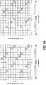
- FIGs. 1A , 1B and 1Cillustrate mappings for several types of references signals, namely, PRS signal mapping, CRS signal mapping, and PSS/SSS signal mapping, respectively.
- PRS signal mappingis illustrated for one, two and four antenna ports.
- the PRS symbol (R 6 )has a diagonal pattern and is placed every sixth subcarrier; therefore the PRS signal has a reuse factor of six.
- the sub-frame that contains the PRS signalis dedicated for PRS transmission to avoid interference (i.e., the sub-frame always contains the PRS signal). It should be noted that the transmission of the PRS signal is reconfigurable. In this regard, the PRS signal can be transmitted across the entirety of the LTE system bandwidth.
- the PRS signalcan be transmitted in N consecutive sub-frames with a certain duration of PRS periodicity, where N varies from 1 to 6 milliseconds (ms) and PRS periodicity varies from 160 to 1280 ms.
- the PRS signalmay be repeated in upto six (6) consecutive sub-frames, but once the N subframes of the PRS signal are exhausted, the PRS signal is not again repeated until the entire frame is completed, i.e., in approximately 160 to 1280 sub-frames or milli-seconds.
- the UEIn response to receiving the PRS signals, the UE performs Observed Time Difference of Arrival (OTDOA) measurements.
- OOA measurementsare calculated by performing cross-correlation on the received PRS signals and locally generated reference signals. Cross correlation from different transmission antennas, receiver antennas and sub-frames is accumulated for the purpose of obtaining exemplary cross-correlation peak. The measured time delay / time of arrival is subsequently determined from the phase information of the cross correlation peak. The previously described processes are repeated to obtain the time delay / time of arrival from several different base stations (e.g ., a reference base station and neighboring base stations).
- base stationse.g ., a reference base station and neighboring base stations.
- OTDOA or Reference Signal Time Difference (RSTD) measurementis calculated by subtracting the time delay / time of arrival of neighboring base stations from the time delay / time of arrival of the reference (i.e., serving) base station.
- the device/UEperforms RSTD measurement quality assessments, such as classifying the RSTD measurement or the like.
- the UEsubsequently transmits all of the RSTD measurements, RSTD measurement quality information, and device types (e.g., MTC device type) to the Location Server, via a reference base station, using LTE Positioning Protocol (LPP).
- LTPLTE Positioning Protocol
- the LSperforms positioning estimations.
- the LTE cellular systemis commonly deployed with a bandwidth in the range of 10 MHZ or 20 MHz. Since MTC devices are targeted to be operated in the narrow 1.4 MHz bandwidth, with the objective of reduced power consumption and reduced implementation cost, such devices are only capable of receiving a part of the overall PRS signal that is typically transmitted in the wider bandwidth.
- CRS signal mappingis illustrated.
- the CRS signalshave the primary purpose to assist data demodulation at the UE.
- CRS signalsare transmitted in each base station antenna port, and the mapping of downlink CRS signals for the case of normal cyclic prefix is shown in FIG. 1B .
- the CRS signalis transmitted across the whole LTE system bandwidth, e.g., 20 MHz, and the CRS signal is transmitted during every sub-frame of a frame transmission (e.g., 1 ms periodicity), as further discussed with reference to FIG. 3 below.
- PSS/SSS signal mappingis illustrated.
- the PSS and SSS signalshave a primary purpose for the UE to perform time and frequency synchronization, cell detection, duplexing mode detection, and cyclic prefix type detection.
- the synchronization signals resource mapping of FIG. 1Cshows the signal periodicity is every 5 sub-frames ( e.g., 5 ms periodicity).
- the synchronization signalsare transmitted in sixty-two (62) sub-carriers around the DC sub-carrier, i.e., within less than 1.4 MHz.
- FIG. 2a diagram illustrates a User Equipment (UE), such as a Machine Type Communication (MTC) device, operating in an environment, in accordance with embodiments of the present invention.
- UEUser Equipment
- MTCMachine Type Communication
- a network environment 200is illustrated in accordance with one embodiment of the present invention.
- the network system 208is operatively coupled, via a network 201 , which includes base stations/eNode-Bs, to the user equipment 204 and/or 206.
- the network system 208may send information to and receive information from the user equipment devices 204 and/or 206, via network 201.
- the user equipment 204 and/or 206are in network communication with base stations/e-Node-Bs 201 and the base stations/e-Node-Bs are in communication with network system 208 which includes a location server operatively configured to determine positioning estimations based on data sent from the user equipment 204 and 206, via base stations/e-Node-Bs 201.
- FIG. 2illustrates only one example of an embodiment of a network environment 200, and it will be appreciated that in other embodiments one or more of the systems, devices, or servers may be combined into a single system, device, or server, or be made up of multiple systems, devices, or servers.
- the network 201may be a telecommunication network, a global area network (GAN), such as the Internet, a wide area network (WAN), a local area network (LAN), or any other type of network or combination of networks.
- GANglobal area network
- the network 201may provide for wireline, wireless, or a combination wireline and wireless communication between devices on the network 201.
- the user 202is an individual who maintains cellular products with one or more providers.
- the network system 208may be or include one or more base stations and/or access points and, in some embodiments, generally includes a communication device 246, a processing device 248, and a memory device 250.
- processing devicegenerally includes circuitry used for implementing the communication and/or logic functions of the particular system.
- a processing devicemay include a digital signal processor device, a microprocessor device, and various analog-to-digital converters, digital-to-analog converters, and other support circuits and/or combinations of the foregoing. Control and signal processing functions of the system are allocated between these processing devices according to their respective capabilities.
- the processing devicemay include functionality to operate one or more software programs based on computer-readable instructions thereof, which may be stored in a memory device.
- the processing device 248is operatively coupled to the communication device 246 and the memory device 250.
- the processing device 248uses the communication device 246 to communicate with the network 201 and other devices on the network 201.
- the communication device 246generally includes a modem, server, or other device for communicating with other devices on the network 201, which may include, for example, transmitting reference signals to LTE devices.
- the network system 208includes computer-readable instructions 254 stored in the memory device 250, which in one embodiment includes the computer-readable instructions 254 of an application 258.
- the memory device 250includes data storage 252 for storing data related to and/or used by the application 258.
- the user equipment 206(e.g., an MTC device) generally includes a communication device 236, a processing device 238, and a memory device 240.
- the processing device 238is operatively coupled to the communication device 236 and the memory device 240.
- the processing device 238may send or receive data from the user equipment 204, and/or the network system 208 via the communication device 236 over a network 201.
- the communication device 236generally includes a modem, server, or other device for communicating with other devices on the network 201.
- the user equipment 206includes computer-readable instructions 242 stored in the memory device 240, which in one embodiment includes the computer-readable instructions 242 of an application 244.
- the application 244allows the user equipment 206 to be linked to the network system 208 to communicate, via a network 201.
- the application 244may also allow the user equipment 206 to connect directly ( i.e., locally or device to device) with the user equipment 204.
- User equipment 204e.g., a mobile communication device, MTC device or the like
- servers, systems, and/or devices described hereinillustrate one embodiment of the invention. It is further understood that one or more of the servers, systems, and devices can be combined in other embodiments and still function in the same or similar way as the embodiments described herein.
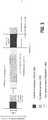
- FIG. 3a diagram illustrates an exemplary reference signal transmission, in accordance with embodiments of the present invention.
- MTC devicesoperate only in a narrow bandwidth, while the PRS signals are transmitted across the entire LTE channel bandwidth (e.g., 10 MHz), and positioning measurements that are based on a part or a sub-set of PRS results in a poor positioning accuracy.
- LTE channel bandwidthe.g. 10 MHz
- the PRS signalis only repeated every 160 sub-frames (or ms). Accordingly, other reference signals that are repeated more often, such as the CRS and synchronization signals, may be used for positioning measurements. Although the CRS and PSS/SSS signals are designed for other than positioning purposes, these signals can be used for positioning related measurements ( i.e., RSTD). This solution obviates a need to transmit a new and improved ( viz . PRS signals) positioning signal.
- the PRS signalhas lower interference, the PRS signal can be boosted, and if necessary, some PRS signals can be muted, the CRS and PSS/SSS signals may provide more accurate positioning measurements than the PRS signals due to their increased periodicity.
- CRS and PSS/SSS signalsmay be used in multiple sub-frames in order to enhance positioning accuracy.
- measurementscan be based on longer window lengths. In other words, measurement window size may be adjusted, and generally speaking, the longer the window size, the more data may be collected, and the more accurate the resulting positioning measurements. On the other hand, if the UE is not stationary, then shorter measurement window sizes are more appropriate.
- M1refers to the measurement window length for CRS-based measurements
- M2refers to the measurement window length for synchronization-based measurements.
- Both M1 and M2may be adjusted so that the CRS-based measurement window and/or the synchronization-based measurement window are adjusted for earlier starts and/or later starts from the reference point.
- the UEit is not necessary for the UE to listen within MTC bandwidth around the DC-subcarrier, especially if there is an active data transmission using the other frequency.
- Both M1 and M2are controlled by the location server.
- the location servermay dictate that M1 is ten (10) sub-frames and that it has early or late start from a predetermined reference point.
- Such a relatively short window lengthmay be reflective of the fact that one or more relevant UEs are non-stationary.
- the location servermay dictate, for example, that M2 is thirty (30) sub-frames and that it has early or late start from a predetermined reference point.
- Such a relatively long window lengthmay be reflective of the fact that one or more relevant UEs are stationary.
- the early start and/or late start of the measurement windowmay be determined based on the periodicity of the PRS signal, and the positioning accuracy based on on-going/existing positioning measurements (e.g . OTDOA measurements).
- the LSmay request the UE provide enhanced positioning accuracy.
- the LSalso provides the window length of M1 and/or M2 as determined by the LS based on the mobility status of the UE and/or the measurement quality.
- the UE mobility statusmay be determined by one or more base stations in communication with the UE. If the base station(s) determine that the UE is operating in a normal mobility state, the LS may set M1 and/or M2 relatively longer than a medium mobility state or a high mobility state.
- the UEsends a velocity status to a base station or the LS. This velocity status may be determined, for example, by the UE using a Doppler shift estimate.
- the base station and/or LSdetermines that M1 and/or M2 are relatively higher values, thereby indicating relatively longer measurement windows.
- the measurement qualitymay be determined by the UE. If the measurement quality is determined to be poor or lower than the required threshold, then the window length may be modified. In some embodiments, the UE mobility is then used to determine the relative window length as described above.
- the UEmeasures the RSTD (or positioning measurement) using the CRS and/or the synchronization reference signals available within the M1 and/or M2 windows, respectively. In some cases, the UE also measures the RSTD of the CRS within the N PRS sub-frames, which all MTC devices typically receive. Moreover, in such embodiments of the invention, it should be noted that the PSS/SSS (Primary Synchronization Signals/Secondary Synchronization Signals) sub-frames and MBSFN (Multicast Broadcast Single Frequency Network) sub-frames include no Positioning Reference Signals (PRSs).
- PRSsPositioning Reference Signals
- the UEsalso determine the quality of positioning measurements for each CRS, synchronization and PRS signal. Then, the UE compares the quality of positioning signal to a threshold, which may be predetermined or contemporaneously determined. In some instances, the UE determines the quality of positioning measurement for the PRS signal and uses the determined quality as the threshold. In some cases, the UE communicates the RSTD of the CRS and/or synchronization signals only if their quality is greater than the threshold.
- the UEthen transmits the measurements made, such as the PRS measurement, the CRS measurement and/or the PSS/SSS measurement.
- the measurementsare transmitted along with their corresponding quality determinations and information linking each measurement with its respective quality determination.
- the first stepis to provide a UE configured to listen for PRS transmissions within an operating bandwidth around the DC sub-carrier and at least one non-PRS signal.
- this bandwidthis a 1.4 MHz bandwidth, which is the bandwidth over which MTC devices are configured to operate.
- the next stepis to receive, at the UE and from one or more base stations, a transmission that includes at least one non-PRS signal.
- a non-PRS signalmay be or include a CRS signal, a PSS signal, an SSS signal and/or the like.
- the next stepis to perform, at the UE, TOA measurements for each base station. The TOA measurements are based on the non-PRS signal. Then, UE calculates OTDOA measurements. In some cases, the UE also performs measurements of the PRS signal as well as the non-PRS signal.
- the next step, as represented by block 440is to transmit, from the UE to a location server, the OTDOA measurements. The location server then performs a positioning estimation of the UE based on the OTDOA measurements.
- a devicemay also be referred to as a UE, a system, or apparatus.
- devicesinclude mobile phones or other mobile computing devices, mobile televisions, laptop computers, smart screens, tablet computers or tablets, portable desktop computers, e-readers, scanners, portable media devices, gaming devices, cameras or other image-capturing devices, headgear, eyewear, watches, bands ( e.g ., wristbands) or other wearable devices, or other portable computing or non-computing devices.
- Each processor described hereingenerally includes circuitry for implementing audio, visual, and/or logic functions.
- the processormay include a digital signal processor device, a microprocessor device, and various analog-to-digital converters, digital-to-analog converters, and other support circuits. Control and signal processing functions of the system in which the processor resides may be allocated between these devices according to their respective capabilities.
- the processormay also include functionality to operate one or more software programs based at least partially on computer-executable program code portions thereof, which may be stored, for example, in a memory.
- Each memorymay include any computer-readable medium.
- memorymay include volatile memory, such as volatile random access memory ("RAM") having a cache area for the temporary storage of data.
- RAMvolatile random access memory
- Memorymay also include non-volatile memory, which may be embedded and/or may be removable.
- the non-volatile memorymay additionally or alternatively include an EEPROM, flash memory, and/or the like.
- the memorymay store any one or more of pieces of information and data used by the system in which it resides to implement the functions of that system.
- any terms expressed in the singular form hereinare meant to also include the plural form and/or vice versa, unless explicitly stated otherwise.
- “at least one”shall mean “one or more” and these phrases are intended to be interchangeable. Accordingly, the terms “a” and/or “an” shall mean “at least one” or “one or more,” even though the phrase “one or more” or “at least one” is also used herein.
- Like numbersrefer to like elements throughout.
- the present inventionmay include and/or be embodied as an apparatus (including, for example, a system, machine, device, computer program product, and/or the like), as a method (including, for example, a business method, computer-implemented process, and/or the like), or as any combination of the foregoing.
- embodiments of the present inventionmay take the form of an entirely business method embodiment, an entirely software embodiment (including firmware, resident software, micro-code, stored procedures, etc.), an entirely hardware embodiment, or an embodiment combining business method, software, and hardware aspects that may generally be referred to herein as a "system.”
- embodiments of the present inventionmay take the form of a computer program product that includes a computer-readable storage medium having one or more computer-executable program code portions stored therein.
- a processorwhich may include one or more processors, may be "configured to" perform a certain function in a variety of ways, including, for example, by having one or more general-purpose circuits perform the function by executing one or more computer-executable program code portions embodied in a computer-readable medium, and/or by having one or more application-specific circuits perform the function.
- the computer-readable mediummay include, but is not limited to, a non-transitory computer-readable medium, such as a tangible electronic, magnetic, optical, electromagnetic, infrared, and/or semiconductor system, device, and/or other apparatus.
- the non-transitory computer-readable mediumincludes a tangible medium such as a portable computer diskette, a hard disk, a random access memory (RAM), a read-only memory (“ROM”), an erasable programmable read-only memory (“EPROM” or Flash memory), a compact disc read-only memory (“CD-ROM”), and/or some other tangible optical and/or magnetic storage device.
- the computer-readable mediummay be transitory, such as, for example, a propagation signal including computer-executable program code portions embodied therein.
- One or more computer-executable program code portions for carrying out operations of the present inventionmay include object-oriented, scripted, and/or unscripted programming languages, such as, for example, Java, Perl, Smalltalk, C++, SAS, SQL, Python, Objective C, JavaScript, and/or the like.
- the one or more computer-executable program code portions for carrying out operations of embodiments of the present inventionare written in conventional procedural programming languages, such as the "C" programming languages and/or similar programming languages.
- the computer program codemay alternatively or additionally be written in one or more multi-paradigm programming languages, such as, for example, F#.
- These one or more computer-executable program code portionsmay be provided to a processor of a general purpose computer, special purpose computer, and/or some other programmable information processing apparatus in order to produce a particular machine, such that the one or more computer-executable program code portions, which execute via the processor of the computer and/or other programmable information processing apparatus, create mechanisms for implementing the steps and/or functions represented by the flowchart(s) and/or block diagram block(s).
- the one or more computer-executable program code portionsmay be stored in a transitory and/or non-transitory computer-readable medium (e.g ., a memory, etc.) that can direct, instruct, and/or cause a computer and/or other programmable information processing apparatus to function in a particular manner, such that the computer-executable program code portions stored in the computer-readable medium produce an article of manufacture including instruction mechanisms which implement the steps and/or functions specified in the flowchart(s) and/or block diagram block(s).
- a transitory and/or non-transitory computer-readable mediume.g ., a memory, etc.
- the one or more computer-executable program code portionsmay also be loaded onto a computer and/or other programmable information processing apparatus to cause a series of operational steps to be performed on the computer and/or other programmable apparatus.
- thisproduces a computer-implemented process such that the one or more computer-executable program code portions which execute on the computer and/or other programmable apparatus provide operational steps to implement the steps specified in the flowchart(s) and/or the functions specified in the block diagram block(s).
- computer-implemented stepsmay be combined with, and/or replaced with, operator- and/or human-implemented steps in order to carry out an embodiment of the present invention.
Landscapes
- Engineering & Computer Science (AREA)
- Computer Networks & Wireless Communication (AREA)
- Signal Processing (AREA)
- Physics & Mathematics (AREA)
- General Physics & Mathematics (AREA)
- Radar, Positioning & Navigation (AREA)
- Remote Sensing (AREA)
- Mobile Radio Communication Systems (AREA)
- Position Fixing By Use Of Radio Waves (AREA)
Description
- In general, embodiments of the invention relate to mobile communication network communications and, more particularly, utilizing multiple reference signals, including common reference signal (CRS) transmissions and/or primary/secondary synchronization signal (PSS/SSS) transmissions from base stations to User Equipment (UE) with the purpose of improving UE positioning accuracy and, specifically positioning accuracy of Machine Type Communication (MTC) devices.
- Machine Type Communications (MTC) is gaining interest in mobile communication industries. It is projected there will be billions of MTC devices to support Machine to Machine (M2M) devices, in addition to Human to Human (H2H) communications. The primary target for MTC is the Internet of Things (IoT). Examples of MTC uses within the IoT include smart meter devices (e.g., gas meters or electricity meters). MTC may also be used in relation to consumer electronic devices (e.g., smart watches, tracking devices,etc.).
- M2M defines a broad label that can be used to describe any technology that enables networked devices to exchange information and perform actions without the manual assistance of humans. Recently, MTC has been discussed in many standardization bodies, including 3GPP (3rd Generation Partnership Project). In the current stage, 3GPP is specifying low cost and enhanced coverage MTC in LTE (Long-Term Evolution) telecommunications. MTC has some benefits over legacy wireless communication technologies, such as conventional mobile communication devices and the like, in particular MTC/M2M devices tend to exhibit low power consumption and are intended to be low cost devices. Specifically, MTC is defined to be operated with a maximum bandwidth of 1.4 MHz (Mega Hertz), which is relatively smaller than legacy LTE devices, such as conventional mobile communication devices that are operated in up to a 20 MHz bandwidth without carrier aggregation.
- MTC can be applied to many applications or use-cases, for example smart meters, vending machines, various type of sensors (including human body sensors), tracking devices,etc. Positioning in an MTC device is important, especially when there is a need to locate the device for inventory purpose and/or emergency localization.
- The document
WO 2011/139201 A1 (ERICSSON TELEFON AB L M [SE]; SIOMINA IANA [SE]; SELEN YNGVE [SE]) 10 November 2011 (2011-11-10) discloses a scheme for carrying out positioning-related measurements in wireless networks, wherein reference signals other than PRS signals ("non-PRS" signals) such as CRS signals are used in addition to PRS signals to improve the positioning accuracy of Observed Time Difference of Arrival (OTDOA) calculations. - 3GPP standardization has defined positioning techniques (i.e., determining current location of the device) for LTE telecommunications since LTE release 9. However, positioning techniques that are suitable and designed for MTC devices have not yet been defined. While in many instances MTC devices will be generally stationary devices, in other use cases, the MTC devices may be mobile devices and, in such use cases, the knowledge of the device's position may be equally as important as positioning of legacy UE, such as conventional mobile communication devices. The fact that MTC devices according to 3GPP Rel-13 are being defined to operate with a maximum bandwidth of 1.4 MHz poses unique problems associated with obtaining accurate positioning.
- Therefore, a need exists to develop apparatus, systems, methods and the like that will improve UE positioning accuracy and, specifically positioning accuracy of Machine Type Communication (MTC) devices.
- The scope of the invention is defined by the appended claims.
- Having thus described embodiments of the invention in general terms, reference will now be made to the accompanying drawings, where:
FIG. 1A is a mapping of Positioning Reference Signals (PRS), in accordance with the prior art;FIG. 1B is a mapping of Common Reference Signals (CRS), in accordance with the prior art;FIG. 1C is a mapping of Primary Synchronization Signals (PSS) and Secondary Synchronization Signals (SSS), in accordance with the prior art;FIG. 2 is a diagram of a User Equipment (UE), such as a Machine Type Communication (MTC) device, operating in an environment, in accordance with embodiments of the present invention;FIG. 3 illustrates an exemplary reference signal transmission, in accordance with embodiments of the present invention; andFIG. 4 is a flowchart illustrating a method for improving User Equipment (UE) positioning accuracy in a mobile communication system in accordance with embodiments of the present invention.- Embodiments of the present invention now may be described more fully hereinafter with reference to the accompanying drawings, in which some, but not all, embodiments of the invention are shown. Indeed, the invention may be embodied in many different forms and should not be construed as limited to the embodiments set forth herein; rather, these embodiments are provided so that this disclosure may satisfy applicable legal requirements. Like numbers refer to like elements throughout.
- A device may be referred to as a node or user equipment ("UE"). For the purpose of sending or receiving data, the device may connect to a wireless local area network ("WLAN") or a mobile communication network (including evolution of 3GPP LTE releases and 5th Generation ("5G") LTE releases). Any network described herein may have one or more base stations ("BS") and/or access points ("AP").
- As discussed in detail herein, the present invention provides for Positioning Reference Signal (PRS) transmissions, common reference signal (CRS) transmissions and/or primary/secondary synchronization signal (PSS/SSS) transmissions from base stations to User Equipment (UE) with the purpose of improving UE positioning accuracy and, specifically positioning accuracy of Machine Type Communication (MTC) devices.
- LTE networks deploy various positioning techniques as a means of determining the current position (i.e., geographic location) of the device/UE. One such positioning technique that is widely deployed in the LTE network is Observed Time Difference of Arrival (OTDOA), which is a Radio Access Technology (RAT) dependent positioning technique. In principle, OTDOA relies on the device/UE receiving PRS signals transmitted from multiple base stations (i.e., all base stations within the network transmit PRS signals, and the device/UE receives PRS signals from specified base stations depending on the UE's current location within the network) and performs observed time difference of arrival (OTDOA) measurements as discussed in further detail below. These measurement results are then transmitted using an LTE positioning protocol (LPP) from the UE to a location server (LS) over the base station(s). The location server then performs positioning estimation calculations.
FIGs. 1A ,1B and1C illustrate mappings for several types of references signals, namely, PRS signal mapping, CRS signal mapping, and PSS/SSS signal mapping, respectively.- Referring to
FIG. 1A , which originates from 3GPP specification 36.211, PRS signal mapping is illustrated for one, two and four antenna ports. In the illustrated mappings the PRS symbol (R6) has a diagonal pattern and is placed every sixth subcarrier; therefore the PRS signal has a reuse factor of six. The sub-frame that contains the PRS signal is dedicated for PRS transmission to avoid interference (i.e., the sub-frame always contains the PRS signal). It should be noted that the transmission of the PRS signal is reconfigurable. In this regard, the PRS signal can be transmitted across the entirety of the LTE system bandwidth. In addition, the PRS signal can be transmitted inN consecutive sub-frames with a certain duration of PRS periodicity, whereN varies from 1 to 6 milliseconds (ms) and PRS periodicity varies from 160 to 1280 ms. In other words, the PRS signal may be repeated in upto six (6) consecutive sub-frames, but once theN subframes of the PRS signal are exhausted, the PRS signal is not again repeated until the entire frame is completed,i.e., in approximately 160 to 1280 sub-frames or milli-seconds. Thus, there are significant delays between instances of the PRSN sub-frames. - In response to receiving the PRS signals, the UE performs Observed Time Difference of Arrival (OTDOA) measurements. In accordance with specific embodiments of the invention, TOA measurements are calculated by performing cross-correlation on the received PRS signals and locally generated reference signals. Cross correlation from different transmission antennas, receiver antennas and sub-frames is accumulated for the purpose of obtaining exemplary cross-correlation peak. The measured time delay / time of arrival is subsequently determined from the phase information of the cross correlation peak. The previously described processes are repeated to obtain the time delay / time of arrival from several different base stations (e.g., a reference base station and neighboring base stations). OTDOA or Reference Signal Time Difference (RSTD) measurement is calculated by subtracting the time delay / time of arrival of neighboring base stations from the time delay / time of arrival of the reference (i.e., serving) base station. In response to determining RSTD measurements, the device/UE performs RSTD measurement quality assessments, such as classifying the RSTD measurement or the like. The UE subsequently transmits all of the RSTD measurements, RSTD measurement quality information, and device types (e.g., MTC device type) to the Location Server, via a reference base station, using LTE Positioning Protocol (LPP). In response to receiving the RSTD measurements and quality information, the LS performs positioning estimations.
- The LTE cellular system is commonly deployed with a bandwidth in the range of 10 MHZ or 20 MHz. Since MTC devices are targeted to be operated in the narrow 1.4 MHz bandwidth, with the objective of reduced power consumption and reduced implementation cost, such devices are only capable of receiving a part of the overall PRS signal that is typically transmitted in the wider bandwidth.
- Referring to
FIG. 1B , which originates from 3GPP specification 36.211, CRS signal mapping is illustrated. The CRS signals have the primary purpose to assist data demodulation at the UE. CRS signals are transmitted in each base station antenna port, and the mapping of downlink CRS signals for the case of normal cyclic prefix is shown inFIG. 1B . The CRS signal is transmitted across the whole LTE system bandwidth, e.g., 20 MHz, and the CRS signal is transmitted during every sub-frame of a frame transmission (e.g., 1 ms periodicity), as further discussed with reference toFIG. 3 below. - Referring to
FIG. 1C , PSS/SSS signal mapping is illustrated. The PSS and SSS signals have a primary purpose for the UE to perform time and frequency synchronization, cell detection, duplexing mode detection, and cyclic prefix type detection. The synchronization signals resource mapping ofFIG. 1C shows the signal periodicity is every 5 sub-frames (e.g., 5 ms periodicity). Typically, the synchronization signals are transmitted in sixty-two (62) sub-carriers around the DC sub-carrier,i.e., within less than 1.4 MHz. - Referring now to
FIG. 2 , a diagram illustrates a User Equipment (UE), such as a Machine Type Communication (MTC) device, operating in an environment, in accordance with embodiments of the present invention. Anetwork environment 200 is illustrated in accordance with one embodiment of the present invention. As illustrated inFIG. 2 , thenetwork system 208 is operatively coupled, via anetwork 201, which includes base stations/eNode-Bs, to the user equipment204 and/or206. In this configuration, thenetwork system 208 may send information to and receive information from the user equipment devices204 and/or206, vianetwork 201. In accordance with the present invention, the user equipment 204 and/or 206 are in network communication with base stations/e-Node-Bs 201 and the base stations/e-Node-Bs are in communication withnetwork system 208 which includes a location server operatively configured to determine positioning estimations based on data sent from the user equipment204 and206, via base stations/e-Node-Bs 201. FIG. 2 illustrates only one example of an embodiment of anetwork environment 200, and it will be appreciated that in other embodiments one or more of the systems, devices, or servers may be combined into a single system, device, or server, or be made up of multiple systems, devices, or servers.- The
network 201 may be a telecommunication network, a global area network (GAN), such as the Internet, a wide area network (WAN), a local area network (LAN), or any other type of network or combination of networks. Thenetwork 201 may provide for wireline, wireless, or a combination wireline and wireless communication between devices on thenetwork 201. In some embodiments, the user202 is an individual who maintains cellular products with one or more providers. - As illustrated in
FIG. 2 , thenetwork system 208 may be or include one or more base stations and/or access points and, in some embodiments, generally includes acommunication device 246, aprocessing device 248, and amemory device 250. As used herein, the term "processing device" generally includes circuitry used for implementing the communication and/or logic functions of the particular system. For example, a processing device may include a digital signal processor device, a microprocessor device, and various analog-to-digital converters, digital-to-analog converters, and other support circuits and/or combinations of the foregoing. Control and signal processing functions of the system are allocated between these processing devices according to their respective capabilities. The processing device may include functionality to operate one or more software programs based on computer-readable instructions thereof, which may be stored in a memory device. - The
processing device 248 is operatively coupled to thecommunication device 246 and thememory device 250. Theprocessing device 248 uses thecommunication device 246 to communicate with thenetwork 201 and other devices on thenetwork 201. As such, thecommunication device 246 generally includes a modem, server, or other device for communicating with other devices on thenetwork 201, which may include, for example, transmitting reference signals to LTE devices. - As further illustrated in
FIG. 2 , thenetwork system 208 includes computer-readable instructions254 stored in thememory device 250, which in one embodiment includes the computer-readable instructions254 of anapplication 258. In some embodiments, thememory device 250 includesdata storage 252 for storing data related to and/or used by theapplication 258. - As illustrated in
FIG. 2 , the user equipment206 (e.g., an MTC device) generally includes acommunication device 236, aprocessing device 238, and amemory device 240. Theprocessing device 238 is operatively coupled to thecommunication device 236 and thememory device 240. In some embodiments, theprocessing device 238 may send or receive data from the user equipment204, and/or thenetwork system 208 via thecommunication device 236 over anetwork 201. As such, thecommunication device 236 generally includes a modem, server, or other device for communicating with other devices on thenetwork 201. - As further illustrated in
FIG. 2 , the user equipment206 includes computer-readable instructions 242 stored in thememory device 240, which in one embodiment includes the computer-readable instructions 242 of anapplication 244. In the embodiment illustrated inFIG. 2 , theapplication 244 allows the user equipment206 to be linked to thenetwork system 208 to communicate, via anetwork 201. Theapplication 244 may also allow the user equipment206 to connect directly (i.e., locally or device to device) with the user equipment204. User equipment204 (e.g., a mobile communication device, MTC device or the like) may include one or more components similar to those described with reference to user equipment206. - It is understood that the servers, systems, and/or devices described herein illustrate one embodiment of the invention. It is further understood that one or more of the servers, systems, and devices can be combined in other embodiments and still function in the same or similar way as the embodiments described herein.
- Referring now to
FIG. 3 , a diagram illustrates an exemplary reference signal transmission, in accordance with embodiments of the present invention. As noted above, MTC devices operate only in a narrow bandwidth, while the PRS signals are transmitted across the entire LTE channel bandwidth (e.g., 10 MHz), and positioning measurements that are based on a part or a sub-set of PRS results in a poor positioning accuracy. - As shown in the network configuration of
FIG. 3 , the PRS signal is only repeated every 160 sub-frames (or ms). Accordingly, other reference signals that are repeated more often, such as the CRS and synchronization signals, may be used for positioning measurements. Although the CRS and PSS/SSS signals are designed for other than positioning purposes, these signals can be used for positioning related measurements (i.e., RSTD). This solution obviates a need to transmit a new and improved (viz. PRS signals) positioning signal. While the CRS and PSS/SSS signals are less robust than the PRS signal, the PRS signal has lower interference, the PRS signal can be boosted, and if necessary, some PRS signals can be muted, the CRS and PSS/SSS signals may provide more accurate positioning measurements than the PRS signals due to their increased periodicity. - CRS and PSS/SSS signals may be used in multiple sub-frames in order to enhance positioning accuracy. As shown in
FIG. 3 , if a UE is stationary, then measurements can be based on longer window lengths. In other words, measurement window size may be adjusted, and generally speaking, the longer the window size, the more data may be collected, and the more accurate the resulting positioning measurements. On the other hand, if the UE is not stationary, then shorter measurement window sizes are more appropriate. - As shown, M1 refers to the measurement window length for CRS-based measurements, and M2 refers to the measurement window length for synchronization-based measurements. Both M1 and M2 may be adjusted so that the CRS-based measurement window and/or the synchronization-based measurement window are adjusted for earlier starts and/or later starts from the reference point. In case of CRS-based measurements, it is not necessary for the UE to listen within MTC bandwidth around the DC-subcarrier, especially if there is an active data transmission using the other frequency. Both M1 and M2 are controlled by the location server. For example, the location server may dictate that M1 is ten (10) sub-frames and that it has early or late start from a predetermined reference point. Such a relatively short window length may be reflective of the fact that one or more relevant UEs are non-stationary. Conversely, the location server may dictate, for example, that M2 is thirty (30) sub-frames and that it has early or late start from a predetermined reference point. Such a relatively long window length may be reflective of the fact that one or more relevant UEs are stationary. Further, the early start and/or late start of the measurement window may be determined based on the periodicity of the PRS signal, and the positioning accuracy based on on-going/existing positioning measurements (e.g. OTDOA measurements).
- In some embodiments, the LS may request the UE provide enhanced positioning accuracy. In some cases, the LS also provides the window length of M1 and/or M2 as determined by the LS based on the mobility status of the UE and/or the measurement quality. The UE mobility status may be determined by one or more base stations in communication with the UE. If the base station(s) determine that the UE is operating in a normal mobility state, the LS may set M1 and/or M2 relatively longer than a medium mobility state or a high mobility state. In some embodiments, the UE sends a velocity status to a base station or the LS. This velocity status may be determined, for example, by the UE using a Doppler shift estimate. The base station and/or LS, in some embodiments, determines that M1 and/or M2 are relatively higher values, thereby indicating relatively longer measurement windows.
- The measurement quality may be determined by the UE. If the measurement quality is determined to be poor or lower than the required threshold, then the window length may be modified. In some embodiments, the UE mobility is then used to determine the relative window length as described above.
- In some embodiments, the UE measures the RSTD (or positioning measurement) using the CRS and/or the synchronization reference signals available within the M1 and/or M2 windows, respectively. In some cases, the UE also measures the RSTD of the CRS within theN PRS sub-frames, which all MTC devices typically receive. Moreover, in such embodiments of the invention, it should be noted that the PSS/SSS (Primary Synchronization Signals/Secondary Synchronization Signals) sub-frames and MBSFN (Multicast Broadcast Single Frequency Network) sub-frames include no Positioning Reference Signals (PRSs).
- The UEs also determine the quality of positioning measurements for each CRS, synchronization and PRS signal. Then, the UE compares the quality of positioning signal to a threshold, which may be predetermined or contemporaneously determined. In some instances, the UE determines the quality of positioning measurement for the PRS signal and uses the determined quality as the threshold. In some cases, the UE communicates the RSTD of the CRS and/or synchronization signals only if their quality is greater than the threshold.
- In various embodiments, the UE then transmits the measurements made, such as the PRS measurement, the CRS measurement and/or the PSS/SSS measurement. In some embodiments, only the measurements that meet the necessary level of quality are transmitted, and in some embodiments, the PRS measurement is always transmitted and other measurements are only transmitted if they meet or exceed the required quality level. In some cases, the measurements are transmitted along with their corresponding quality determinations and information linking each measurement with its respective quality determination.
- Referring now to
FIG. 4 , a flowchart illustrates a method for improving User Equipment (UE) positioning accuracy in a mobile communication system in accordance with embodiments of the present invention. The first step, as illustrated by block410, is to provide a UE configured to listen for PRS transmissions within an operating bandwidth around the DC sub-carrier and at least one non-PRS signal. In some embodiments, this bandwidth is a 1.4 MHz bandwidth, which is the bandwidth over which MTC devices are configured to operate. - The next step, represented by
block 420, is to receive, at the UE and from one or more base stations, a transmission that includes at least one non-PRS signal. A non-PRS signal may be or include a CRS signal, a PSS signal, an SSS signal and/or the like. The next step, as represented byblock 430, is to perform, at the UE, TOA measurements for each base station. The TOA measurements are based on the non-PRS signal. Then, UE calculates OTDOA measurements. In some cases, the UE also performs measurements of the PRS signal as well as the non-PRS signal. The next step, as represented byblock 440, is to transmit, from the UE to a location server, the OTDOA measurements. The location server then performs a positioning estimation of the UE based on the OTDOA measurements. - The invention is not limited to any particular types of devices (either Machine Type Communication (MTC) devices or non-MTC devices). As used herein, a device may also be referred to as a UE, a system, or apparatus. Examples of devices include mobile phones or other mobile computing devices, mobile televisions, laptop computers, smart screens, tablet computers or tablets, portable desktop computers, e-readers, scanners, portable media devices, gaming devices, cameras or other image-capturing devices, headgear, eyewear, watches, bands (e.g., wristbands) or other wearable devices, or other portable computing or non-computing devices.
- Each processor described herein generally includes circuitry for implementing audio, visual, and/or logic functions. For example, the processor may include a digital signal processor device, a microprocessor device, and various analog-to-digital converters, digital-to-analog converters, and other support circuits. Control and signal processing functions of the system in which the processor resides may be allocated between these devices according to their respective capabilities. The processor may also include functionality to operate one or more software programs based at least partially on computer-executable program code portions thereof, which may be stored, for example, in a memory.
- Each memory may include any computer-readable medium. For example, memory may include volatile memory, such as volatile random access memory ("RAM") having a cache area for the temporary storage of data. Memory may also include non-volatile memory, which may be embedded and/or may be removable. The non-volatile memory may additionally or alternatively include an EEPROM, flash memory, and/or the like. The memory may store any one or more of pieces of information and data used by the system in which it resides to implement the functions of that system.
- The various features described with respect to any embodiments described herein are applicable to any of the other embodiments described herein. As used herein, the terms data and information may be used interchangeably. Although many embodiments of the present invention have just been described above, the present invention may be embodied in many different forms and should not be construed as limited to the embodiments set forth herein; rather, these embodiments are provided so that this disclosure will satisfy applicable legal requirements. Also, it will be understood that, where possible, any of the advantages, features, functions, devices, and/or operational aspects of any of the embodiments of the present invention described and/or contemplated herein may be included in any of the other embodiments of the present invention described and/or contemplated herein, and/or vice versa. In addition, where possible, any terms expressed in the singular form herein are meant to also include the plural form and/or vice versa, unless explicitly stated otherwise. As used herein, "at least one" shall mean "one or more" and these phrases are intended to be interchangeable. Accordingly, the terms "a" and/or "an" shall mean "at least one" or "one or more," even though the phrase "one or more" or "at least one" is also used herein. Like numbers refer to like elements throughout.
- As will be appreciated by one of ordinary skill in the art in view of this disclosure, the present invention may include and/or be embodied as an apparatus (including, for example, a system, machine, device, computer program product, and/or the like), as a method (including, for example, a business method, computer-implemented process, and/or the like), or as any combination of the foregoing. Accordingly, embodiments of the present invention may take the form of an entirely business method embodiment, an entirely software embodiment (including firmware, resident software, micro-code, stored procedures, etc.), an entirely hardware embodiment, or an embodiment combining business method, software, and hardware aspects that may generally be referred to herein as a "system." Furthermore, embodiments of the present invention may take the form of a computer program product that includes a computer-readable storage medium having one or more computer-executable program code portions stored therein. As used herein, a processor, which may include one or more processors, may be "configured to" perform a certain function in a variety of ways, including, for example, by having one or more general-purpose circuits perform the function by executing one or more computer-executable program code portions embodied in a computer-readable medium, and/or by having one or more application-specific circuits perform the function.
- It will be understood that any suitable computer-readable medium may be utilized. The computer-readable medium may include, but is not limited to, a non-transitory computer-readable medium, such as a tangible electronic, magnetic, optical, electromagnetic, infrared, and/or semiconductor system, device, and/or other apparatus. For example, in some embodiments, the non-transitory computer-readable medium includes a tangible medium such as a portable computer diskette, a hard disk, a random access memory (RAM), a read-only memory ("ROM"), an erasable programmable read-only memory ("EPROM" or Flash memory), a compact disc read-only memory ("CD-ROM"), and/or some other tangible optical and/or magnetic storage device. In other embodiments of the present invention, however, the computer-readable medium may be transitory, such as, for example, a propagation signal including computer-executable program code portions embodied therein.
- One or more computer-executable program code portions for carrying out operations of the present invention may include object-oriented, scripted, and/or unscripted programming languages, such as, for example, Java, Perl, Smalltalk, C++, SAS, SQL, Python, Objective C, JavaScript, and/or the like. In some embodiments, the one or more computer-executable program code portions for carrying out operations of embodiments of the present invention are written in conventional procedural programming languages, such as the "C" programming languages and/or similar programming languages. The computer program code may alternatively or additionally be written in one or more multi-paradigm programming languages, such as, for example, F#.
- Some embodiments of the present invention are described herein with reference to flowchart illustrations and/or block diagrams of apparatus and/or methods. It will be understood that each block included in the flowchart illustrations and/or block diagrams, and/or combinations of blocks included in the flowchart illustrations and/or block diagrams, may be implemented by one or more computer-executable program code portions. These one or more computer-executable program code portions may be provided to a processor of a general purpose computer, special purpose computer, and/or some other programmable information processing apparatus in order to produce a particular machine, such that the one or more computer-executable program code portions, which execute via the processor of the computer and/or other programmable information processing apparatus, create mechanisms for implementing the steps and/or functions represented by the flowchart(s) and/or block diagram block(s).
- The one or more computer-executable program code portions may be stored in a transitory and/or non-transitory computer-readable medium (e.g., a memory, etc.) that can direct, instruct, and/or cause a computer and/or other programmable information processing apparatus to function in a particular manner, such that the computer-executable program code portions stored in the computer-readable medium produce an article of manufacture including instruction mechanisms which implement the steps and/or functions specified in the flowchart(s) and/or block diagram block(s).
- The one or more computer-executable program code portions may also be loaded onto a computer and/or other programmable information processing apparatus to cause a series of operational steps to be performed on the computer and/or other programmable apparatus. In some embodiments, this produces a computer-implemented process such that the one or more computer-executable program code portions which execute on the computer and/or other programmable apparatus provide operational steps to implement the steps specified in the flowchart(s) and/or the functions specified in the block diagram block(s). Alternatively, computer-implemented steps may be combined with, and/or replaced with, operator- and/or human-implemented steps in order to carry out an embodiment of the present invention.
Claims (15)
- A method for improved User Equipment (UE) positioning accuracy in a mobile communication system (200), the method comprising:providing for a UE (204, 206) configured to listen for Positioning Reference Signal (PRS) transmissions within an operating bandwidth around Direct Current (DC) sub-carrier and at least one non-PRS transmission;receiving, at the UE (204, 206), PRS and non-PRS transmissions transmitted from base stations (201) within the operating bandwidth;determining, at the UE (204, 206), for each of the base stations (201), a PRS positioning measurement based on the PRS transmissions and a non-PRS positioning measurement based on the non-PRS transmissions;determining, at the UE (204, 206), for each of the base stations (201), a non-PRS measurement quality corresponding to the non-PRS positioning measurement;comparing, at the UE (204, 206), the non-PRS measurement quality to a measurement quality threshold, andtransmitting, from the UE (204, 206) to a Location Server (LS) (208),(i) the PRS positioning measurements, and in response to the comparing indicating that one or more of the non-PRS measurement qualities are greater than the measurement quality threshold,(ii) the non-PRS positioning measurements associated with the one or more non-PRS measurement qualities,wherein the LS (208) performs a positioning estimation of the UE (204, 206) based on the received PRS positioning measurements and non-PRS positioning measurements.
- The method of claim 1, wherein providing for the UE (204, 206) comprises providing for a Machine Type Communications (MTC) UE (206) configured to listen for the PRS and non-PRS transmissions within a Machine Type Communication (MTC) MTC operating bandwidth of approximately 1.4 MHz.
- The method of claim 1 or claim 2, wherein the non-PRS transmission comprises a plurality of sub-frames and wherein each of the plurality of sub-frames of the non-PRS transmission comprises a Common Reference Signal (CRS).
- The method of any one of claims 1-3, wherein the non-PRS signal comprises a synchronization signal comprising a Primary Synchronization Signal (PSS) and/or a Secondary Synchronization Signal (SSS).
- The method of claim 4, wherein the non-PRS transmission comprises a plurality of sub-frames successive in time and wherein every fifth (5th) sub-frame comprises the synchronization signal.
- The method of any one of claims 1-5, wherein the non-PRS transmission further comprises a positioning reference signal and wherein performing the OTDOA measurements are further based on the positioning reference signal.
- The method of any one of claims 1-6, further comprising:receiving, at the UE (204, 206) from the LS (208), a request for enhanced positioning accuracy; andinitiating, at the UE (204, 206) and in response to the request from the LS (208), performing the OTDOA measurements based on the at least one non-PRS transmission.
- The method of any one of claims 1-7, further comprising:receiving, at the UE (204, 206) from the LS (208), a window length for performing measurements based on the at least one non-PRS transmission; andwherein performing measurements is further based on the received window length.
- The method of any one of claims 1-8, further comprising:receiving, at the UE (204, 206) from the LS (208), an early/late start indicator, wherein the early/late start indicator indicates an early or late start in relation to a predetermined reference point for a window for performing measurements based on the at least one non-PRS transmission; andwherein performing measurements is further based on the received early/late start indicator.
- The method of claim 1, further comprising:determining a PRS measurement quality corresponding to the PRS positioning measurement; andwherein the measurement quality threshold is the determined PRS measurement quality.
- The method of claim 10, further comprising:transmitting, from the UE (204, 206) to the LS (208), the PRS measurement quality and information indicating the PRS measurement quality corresponds to the PRS positioning measurement; andtransmitting, from the UE (204, 206) to the LS (208), the non-PRS measurement quality and information indicating the non-PRS measurement quality corresponds to the non-PRS positioning measurement.
- A mobile communication system (200) for improved User Equipment (UE) positioning accuracy, the system comprising:a plurality of base stations (201);a location server (LS) (208);a user equipment (UE) (204, 206) operably connected to at least one of the base stations (201), the UE (204, 206) configured to:listen for Positioning Reference Signal (PRS) transmissions within an operating bandwidth around Direct Current (DC) sub-carrier and at least one non-PRS transmission;receive PRS and non-PRS transmissions transmitted from base stations (201) within the operating bandwidth;determine, for each of the base stations (201), a PRS positioning measurement based on the PRS transmissions and a non-PRS positioning measurement based on the non-PRS transmissions;determine, for each of the base stations (201), a non-PRS measurement quality corresponding to the non-PRS positioning measurement;compare, the non-PRS measurement quality to a measurement quality threshold;transmit, from the UE (204, 206) to the LS (208)(i) the PRS positioning measurements, and in response to the comparing indicating that one or more of the non-PRS measurement qualitites are greater than the measurement quality threshold,(ii) the non-PRS positioning measurements associated with the one or more non-PRS measurement qualities,wherein the LS (208) is configured to perform a positioning estimation of the UE (204, 206) based on the received PRS positioning measurements and non-PRS positioning measurements.
- The mobile communication system (200) of claim 12, wherein the mobile communication system (200) is configured to perform the method of any one of claims 1-11.
- A user equipment (204, 206) for a mobile communication system (200), wherein the user equipment (204, 206) is configured to perform the method of any one of claims 1 -11.
- A computer program product, comprising a non-transitory computer-readable medium comprising computer-executable instructions for improved User Equipment (UE) positioning accuracy in a mobile communication system (200), wherein the instructions are configured to cause a processing device (238, 248) to perform the method of any one of claims 1-11.
Priority Applications (1)
| Application Number | Priority Date | Filing Date | Title |
|---|---|---|---|
| EP19170056.6AEP3544342B1 (en) | 2015-03-30 | 2015-03-30 | Apparatus and method for mobile network positioning of mtc devices using common reference or synchronization signals |
Applications Claiming Priority (1)
| Application Number | Priority Date | Filing Date | Title |
|---|---|---|---|
| PCT/EP2015/056891WO2016155774A1 (en) | 2015-03-30 | 2015-03-30 | Apparatus, systems and methods for mobile network positioning of mtc devices using common reference or synchronization signals |
Related Child Applications (1)
| Application Number | Title | Priority Date | Filing Date |
|---|---|---|---|
| EP19170056.6ADivisionEP3544342B1 (en) | 2015-03-30 | 2015-03-30 | Apparatus and method for mobile network positioning of mtc devices using common reference or synchronization signals |
Publications (2)
| Publication Number | Publication Date |
|---|---|
| EP3278607A1 EP3278607A1 (en) | 2018-02-07 |
| EP3278607B1true EP3278607B1 (en) | 2019-04-24 |
Family
ID=52811110
Family Applications (2)
| Application Number | Title | Priority Date | Filing Date |
|---|---|---|---|
| EP15714190.4AActiveEP3278607B1 (en) | 2015-03-30 | 2015-03-30 | Apparatus, system and method for mobile network positioning of mtc devices using common reference or synchronization signals |
| EP19170056.6AActiveEP3544342B1 (en) | 2015-03-30 | 2015-03-30 | Apparatus and method for mobile network positioning of mtc devices using common reference or synchronization signals |
Family Applications After (1)
| Application Number | Title | Priority Date | Filing Date |
|---|---|---|---|
| EP19170056.6AActiveEP3544342B1 (en) | 2015-03-30 | 2015-03-30 | Apparatus and method for mobile network positioning of mtc devices using common reference or synchronization signals |
Country Status (4)
| Country | Link |
|---|---|
| US (1) | US9877161B2 (en) |
| EP (2) | EP3278607B1 (en) |
| CN (1) | CN107466370B (en) |
| WO (1) | WO2016155774A1 (en) |
Families Citing this family (31)
| Publication number | Priority date | Publication date | Assignee | Title |
|---|---|---|---|---|
| CA2984482C (en)* | 2015-05-15 | 2020-06-30 | Telefonaktiebolaget L M Ericsson (Publ) | Methods and nodes for managing rstd reports |
| CN107852314B (en)* | 2015-07-27 | 2021-12-10 | 苹果公司 | System and method for system operation of narrowband LTE for cellular IoT |
| CN107836136B (en)* | 2015-08-13 | 2021-02-09 | 华为技术有限公司 | Synchronization method and device |
| KR102341280B1 (en)* | 2015-10-08 | 2021-12-21 | 삼성전자주식회사 | Communication device and control method thereof |
| US10469516B2 (en)* | 2016-04-28 | 2019-11-05 | Qualcomm Incorporated | Techniques for associating measurement data acquired at a wireless communication device with current values of time and location obtained by a user equipment and acknowledged by the wireless communication device |
| GB2557889B (en)* | 2016-05-24 | 2019-02-20 | Samsung Electronics Co Ltd | System information provision |
| US11122535B2 (en)* | 2016-07-15 | 2021-09-14 | Qualcomm Incorporated | Techniques for locating devices using narrowband positioning reference signals |
| US10045325B2 (en) | 2016-08-12 | 2018-08-07 | Innovative Technology Lab Co., Ltd. | Method and apparatus for transmitting/receiving positioning reference signal in wireless communication system |
| US10631301B2 (en)* | 2016-09-30 | 2020-04-21 | Qualcomm Incorporated | Positioning reference signal enhancements |
| WO2018085078A1 (en)* | 2016-11-04 | 2018-05-11 | Intel IP Corporation | Reference signal time difference (rstd) measurements for observed time difference of arrival (otdoa) positioning |
| US11997563B2 (en) | 2016-11-23 | 2024-05-28 | Qualcomm Incorporated | Enhancements to observed time difference of arrival positioning of a mobile device |
| EP3549300B1 (en) | 2016-12-05 | 2020-10-28 | Telefonaktiebolaget LM Ericsson (publ.) | Controlling cell-specific reference signal (crs) bandwidth on a lean carrier based on another reference signal bandwidth |
| CN114900887B (en) | 2017-04-03 | 2025-08-26 | 苹果公司 | User equipment apparatus and computer-readable medium |
| US10560237B2 (en) | 2017-05-30 | 2020-02-11 | Qualcomm Incorporated | Cell-specific reference signal transmissions for evolved machine type communication |
| US10375669B2 (en)* | 2017-08-04 | 2019-08-06 | Qualcomm Incorporated | Methods and systems for locating a mobile device using an asynchronous wireless network |
| WO2019127246A1 (en)* | 2017-12-28 | 2019-07-04 | 华为技术有限公司 | Positioning measurement method and device |
| US11445469B2 (en) | 2018-02-09 | 2022-09-13 | Telefonaktiebolaget Lm Ericsson (Publ) | Method, apparatus and system for determining a position of a wireless device |
| US20190313370A1 (en)* | 2018-04-05 | 2019-10-10 | Qualcomm Incorporated | Crs-based unicast pdsch transmission in mbsfn subframes |
| US10588136B2 (en)* | 2018-05-25 | 2020-03-10 | Qualcomm Incorporated | Restrict the positioning reference signal bandwidth in NB-IoT to save power |
| US10917184B2 (en)* | 2018-05-29 | 2021-02-09 | Qualcomm Incorporated | Computing and reporting a relevance metric for a positioning beacon beam |
| US11399356B2 (en)* | 2018-06-26 | 2022-07-26 | Qualcomm Incorporated | Synchronization signal block (SSB)-based positioning measurement signals |
| EP3857252A4 (en)* | 2018-09-28 | 2022-06-22 | Apple Inc. | Techniques for improving new radio (nr) positioning performance |
| ES2983838T3 (en)* | 2018-10-12 | 2024-10-24 | Oq Tech S A R L | Method and system for non-terrestrial cellular wireless communication networks |
| KR102674149B1 (en)* | 2019-02-14 | 2024-06-13 | 애플 인크. | Downlink (DL) Positioning Reference Signal (PRS) Bandwidth Part (BWP) Configuration Reference Signal Design and User Equipment (UE)-based Positioning Enhancements for New Over-the-Radio (NR) Positioning |
| CN111726857B (en)* | 2019-03-18 | 2021-07-20 | 大唐移动通信设备有限公司 | Clock offset determination and processing method, device and system |
| WO2020191646A1 (en)* | 2019-03-27 | 2020-10-01 | Nokia Shanghai Bell Co., Ltd. | Wireless positioning measurement |
| CN112235757B (en)* | 2019-07-15 | 2024-03-12 | 上海诺基亚贝尔股份有限公司 | Method, apparatus, device and computer readable storage medium for positioning |
| US12108271B2 (en)* | 2020-09-02 | 2024-10-01 | Qualcomm Incorporated | Measurement report for sidelink-assisted positioning |
| WO2022061617A1 (en)* | 2020-09-23 | 2022-03-31 | Nokia Shanghai Bell Co., Ltd. | Positioning reference signal transmission triggered by sounding reference signal |
| WO2022073171A1 (en)* | 2020-10-09 | 2022-04-14 | Nokia Shanghai Bell Co., Ltd. | Method and apparatus for positioning reference signal transmission and reception |
| CN114650499B (en)* | 2020-12-21 | 2023-09-15 | 维沃移动通信有限公司 | Positioning measurement methods, devices, equipment and readable storage media |
Family Cites Families (23)
| Publication number | Priority date | Publication date | Assignee | Title |
|---|---|---|---|---|
| US8509323B2 (en)* | 2006-08-22 | 2013-08-13 | Motorola Mobility Llc | Resource allocation including a DC sub-carrier in a wireless communication system |
| KR100956754B1 (en)* | 2006-12-29 | 2010-05-12 | 삼성전자주식회사 | Apparatus and method for estimating the position of a terminal in a broadband wireless communication system |
| EP3334226B1 (en)* | 2009-02-05 | 2020-03-25 | Apple Inc. | Method and system for user equipment location determination on a wireless transmission system |
| KR101593702B1 (en)* | 2009-03-22 | 2016-02-15 | 엘지전자 주식회사 | Method and apparatus for reference signal in wireless communication system |
| US8730925B2 (en)* | 2009-04-09 | 2014-05-20 | Motorola Mobility Llc | Method and apparatus for generating reference signals for accurate time-difference of arrival estimation |
| US8780688B2 (en)* | 2009-04-27 | 2014-07-15 | Telefonaktiebolaget Lm Ericsson (Publ) | Methods and apparatus in a wireless communication system |
| KR101703860B1 (en)* | 2009-05-05 | 2017-02-22 | 엘지전자 주식회사 | Apparatus and metheod for positioing a user equipment |
| US8838141B2 (en)* | 2009-05-29 | 2014-09-16 | Telefonaktiebolaget L M Ericsson (Publ) | Signalling measurements for positioning in a wireless network |
| US8965395B2 (en)* | 2009-06-05 | 2015-02-24 | Qualcomm Incorporated | Positioning of user equipment in a wireless communication network |
| JP4901967B2 (en)* | 2010-02-17 | 2012-03-21 | 株式会社エヌ・ティ・ティ・ドコモ | Positioning time interval control device and positioning time interval control method |
| AU2011249087C1 (en)* | 2010-05-03 | 2015-06-11 | Telefonaktiebolaget L M Ericsson (Publ) | Methods and apparatus for positioning measurements in multi-antenna transmission systems |
| US9344248B2 (en)* | 2010-11-12 | 2016-05-17 | Google Technology Holdings LLC | Positioning reference signal assistance data signaling for enhanced interference coordination in a wireless communication network |
| JP2014512145A (en)* | 2011-04-13 | 2014-05-19 | インターデイジタル パテント ホールディングス インコーポレイテッド | Method and apparatus for small cell discovery in heterogeneous networks |
| GB2491858C (en)* | 2011-06-14 | 2020-07-29 | Sca Ipla Holdings Inc | Telecommunications method and system |
| US20130033999A1 (en)* | 2011-08-05 | 2013-02-07 | Telefonaktiebolaget Lm Ericsson (Publ) | Node and methods therein for enhanced positioning with complementary positioning information |
| CN106353723B (en)* | 2011-11-04 | 2019-12-13 | 瑞典爱立信有限公司 | Positioning of user equipment based on virtual reference measurements |
| CN103209475B (en)* | 2012-01-16 | 2016-05-25 | 华为技术有限公司 | Localization method, location-server, terminal and base station |
| CN102869038B (en)* | 2012-08-24 | 2015-01-21 | 华为技术有限公司 | Measurement compensation method and device in positioning of base station, server and system |
| US20150011238A1 (en)* | 2013-07-05 | 2015-01-08 | Broadcom Corporation | Unilateral Geolocation for Mobile Terminals |
| JP6193675B2 (en)* | 2013-08-21 | 2017-09-06 | 株式会社Nttドコモ | Wireless base station, user terminal, and wireless communication method |
| EP3024273B1 (en)* | 2013-08-22 | 2018-03-21 | Huawei Technologies Co., Ltd. | Signal measuring method and device |
| CN104796218B (en)* | 2014-01-17 | 2019-02-12 | 电信科学技术研究院 | Method for transmitting signals and device |
| US10034253B2 (en)* | 2014-11-17 | 2018-07-24 | Telefonaktiebolaget Lm Ericsson (Publ) | Cell search procedure frame format |
- 2015
- 2015-03-30EPEP15714190.4Apatent/EP3278607B1/enactiveActive
- 2015-03-30CNCN201580078619.7Apatent/CN107466370B/enactiveActive
- 2015-03-30WOPCT/EP2015/056891patent/WO2016155774A1/ennot_activeCeased
- 2015-03-30EPEP19170056.6Apatent/EP3544342B1/enactiveActive
- 2015-07-22USUS14/806,091patent/US9877161B2/enactiveActive
Non-Patent Citations (1)
| Title |
|---|
| None* |
Also Published As
| Publication number | Publication date |
|---|---|
| EP3544342B1 (en) | 2020-07-15 |
| CN107466370B (en) | 2023-06-20 |
| US20160295374A1 (en) | 2016-10-06 |
| US9877161B2 (en) | 2018-01-23 |
| WO2016155774A1 (en) | 2016-10-06 |
| EP3544342A1 (en) | 2019-09-25 |
| EP3278607A1 (en) | 2018-02-07 |
| CN107466370A (en) | 2017-12-12 |
Similar Documents
| Publication | Publication Date | Title |
|---|---|---|
| EP3278607B1 (en) | Apparatus, system and method for mobile network positioning of mtc devices using common reference or synchronization signals | |
| US9709664B2 (en) | Apparatus, systems and methods for mobile network positioning of MTC devices using partial power boosting | |
| US11310762B2 (en) | Method for idle-mode positioning of UEs using observed time difference of arrival | |
| CN113475101B (en) | Uplink positioning of idle or inactive end devices | |
| CN111989584B (en) | Observed time difference of arrival (OTDOA) positioning in Licensed Assisted Access (LAA) | |
| CN113632549B (en) | Wireless positioning measurement | |
| AU2013258868B2 (en) | Wireless positioning | |
| EP3552443B1 (en) | Methods and apparatus for reporting rstd values | |
| US9404997B2 (en) | Communication station and method for time-of-flight positioning using cooperating stations | |
| CN112166564B (en) | Limiting positioning reference signal bandwidth in NB-IOT to save power | |
| WO2019112647A1 (en) | Enhanced time difference of arrival in radio frequency wireless communications | |
| EP3777296B1 (en) | Orthogonality and encapsulation for positioning and navigation signals | |
| US20250141658A1 (en) | Selecting secure sequences for radio frequency communication and positioning applications | |
| US20250287348A1 (en) | Method by which first terminal measures position on basis of sound wave signals in wireless communication system, and apparatus therefor | |
| US20250039846A1 (en) | Direction aware radio resource selection for direct communication between wireless devices | |
| US20250105965A1 (en) | Reference signal configuration | |
| CN113438630B (en) | Method and device for realizing Bluetooth positioning by software | |
| WO2018231727A1 (en) | Enhanced location measurements for wireless communication | |
| US20230328682A1 (en) | Determining timing offset for improved positioning accuracy |
Legal Events
| Date | Code | Title | Description |
|---|---|---|---|
| STAA | Information on the status of an ep patent application or granted ep patent | Free format text:STATUS: THE INTERNATIONAL PUBLICATION HAS BEEN MADE | |
| PUAI | Public reference made under article 153(3) epc to a published international application that has entered the european phase | Free format text:ORIGINAL CODE: 0009012 | |
| STAA | Information on the status of an ep patent application or granted ep patent | Free format text:STATUS: REQUEST FOR EXAMINATION WAS MADE | |
| 17P | Request for examination filed | Effective date:20171025 | |
| AK | Designated contracting states | Kind code of ref document:A1 Designated state(s):AL AT BE BG CH CY CZ DE DK EE ES FI FR GB GR HR HU IE IS IT LI LT LU LV MC MK MT NL NO PL PT RO RS SE SI SK SM TR | |
| AX | Request for extension of the european patent | Extension state:BA ME | |
| DAV | Request for validation of the european patent (deleted) | ||
| DAX | Request for extension of the european patent (deleted) | ||
| GRAJ | Information related to disapproval of communication of intention to grant by the applicant or resumption of examination proceedings by the epo deleted | Free format text:ORIGINAL CODE: EPIDOSDIGR1 | |
| GRAP | Despatch of communication of intention to grant a patent | Free format text:ORIGINAL CODE: EPIDOSNIGR1 | |
| GRAP | Despatch of communication of intention to grant a patent | Free format text:ORIGINAL CODE: EPIDOSNIGR1 | |
| STAA | Information on the status of an ep patent application or granted ep patent | Free format text:STATUS: GRANT OF PATENT IS INTENDED | |
| INTG | Intention to grant announced | Effective date:20181009 | |
| GRAS | Grant fee paid | Free format text:ORIGINAL CODE: EPIDOSNIGR3 | |
| GRAA | (expected) grant | Free format text:ORIGINAL CODE: 0009210 | |
| STAA | Information on the status of an ep patent application or granted ep patent | Free format text:STATUS: THE PATENT HAS BEEN GRANTED | |
| AK | Designated contracting states | Kind code of ref document:B1 Designated state(s):AL AT BE BG CH CY CZ DE DK EE ES FI FR GB GR HR HU IE IS IT LI LT LU LV MC MK MT NL NO PL PT RO RS SE SI SK SM TR | |
| REG | Reference to a national code | Ref country code:GB Ref legal event code:FG4D | |
| REG | Reference to a national code | Ref country code:CH Ref legal event code:EP | |
| REG | Reference to a national code | Ref country code:AT Ref legal event code:REF Ref document number:1125614 Country of ref document:AT Kind code of ref document:T Effective date:20190515 Ref country code:IE Ref legal event code:FG4D | |
| REG | Reference to a national code | Ref country code:DE Ref legal event code:R096 Ref document number:602015028827 Country of ref document:DE | |
| REG | Reference to a national code | Ref country code:NL Ref legal event code:MP Effective date:20190424 | |
| REG | Reference to a national code | Ref country code:LT Ref legal event code:MG4D | |
| PG25 | Lapsed in a contracting state [announced via postgrant information from national office to epo] | Ref country code:NL Free format text:LAPSE BECAUSE OF FAILURE TO SUBMIT A TRANSLATION OF THE DESCRIPTION OR TO PAY THE FEE WITHIN THE PRESCRIBED TIME-LIMIT Effective date:20190424 | |
| PG25 | Lapsed in a contracting state [announced via postgrant information from national office to epo] | Ref country code:AL Free format text:LAPSE BECAUSE OF FAILURE TO SUBMIT A TRANSLATION OF THE DESCRIPTION OR TO PAY THE FEE WITHIN THE PRESCRIBED TIME-LIMIT Effective date:20190424 Ref country code:PT Free format text:LAPSE BECAUSE OF FAILURE TO SUBMIT A TRANSLATION OF THE DESCRIPTION OR TO PAY THE FEE WITHIN THE PRESCRIBED TIME-LIMIT Effective date:20190824 Ref country code:ES Free format text:LAPSE BECAUSE OF FAILURE TO SUBMIT A TRANSLATION OF THE DESCRIPTION OR TO PAY THE FEE WITHIN THE PRESCRIBED TIME-LIMIT Effective date:20190424 Ref country code:FI Free format text:LAPSE BECAUSE OF FAILURE TO SUBMIT A TRANSLATION OF THE DESCRIPTION OR TO PAY THE FEE WITHIN THE PRESCRIBED TIME-LIMIT Effective date:20190424 Ref country code:LT Free format text:LAPSE BECAUSE OF FAILURE TO SUBMIT A TRANSLATION OF THE DESCRIPTION OR TO PAY THE FEE WITHIN THE PRESCRIBED TIME-LIMIT Effective date:20190424 Ref country code:SE Free format text:LAPSE BECAUSE OF FAILURE TO SUBMIT A TRANSLATION OF THE DESCRIPTION OR TO PAY THE FEE WITHIN THE PRESCRIBED TIME-LIMIT Effective date:20190424 Ref country code:NO Free format text:LAPSE BECAUSE OF FAILURE TO SUBMIT A TRANSLATION OF THE DESCRIPTION OR TO PAY THE FEE WITHIN THE PRESCRIBED TIME-LIMIT Effective date:20190724 Ref country code:HR Free format text:LAPSE BECAUSE OF FAILURE TO SUBMIT A TRANSLATION OF THE DESCRIPTION OR TO PAY THE FEE WITHIN THE PRESCRIBED TIME-LIMIT Effective date:20190424 | |
| PG25 | Lapsed in a contracting state [announced via postgrant information from national office to epo] | Ref country code:LV Free format text:LAPSE BECAUSE OF FAILURE TO SUBMIT A TRANSLATION OF THE DESCRIPTION OR TO PAY THE FEE WITHIN THE PRESCRIBED TIME-LIMIT Effective date:20190424 Ref country code:PL Free format text:LAPSE BECAUSE OF FAILURE TO SUBMIT A TRANSLATION OF THE DESCRIPTION OR TO PAY THE FEE WITHIN THE PRESCRIBED TIME-LIMIT Effective date:20190424 Ref country code:GR Free format text:LAPSE BECAUSE OF FAILURE TO SUBMIT A TRANSLATION OF THE DESCRIPTION OR TO PAY THE FEE WITHIN THE PRESCRIBED TIME-LIMIT Effective date:20190725 Ref country code:BG Free format text:LAPSE BECAUSE OF FAILURE TO SUBMIT A TRANSLATION OF THE DESCRIPTION OR TO PAY THE FEE WITHIN THE PRESCRIBED TIME-LIMIT Effective date:20190724 Ref country code:RS Free format text:LAPSE BECAUSE OF FAILURE TO SUBMIT A TRANSLATION OF THE DESCRIPTION OR TO PAY THE FEE WITHIN THE PRESCRIBED TIME-LIMIT Effective date:20190424 | |
| REG | Reference to a national code | Ref country code:AT Ref legal event code:MK05 Ref document number:1125614 Country of ref document:AT Kind code of ref document:T Effective date:20190424 | |
| PG25 | Lapsed in a contracting state [announced via postgrant information from national office to epo] | Ref country code:IS Free format text:LAPSE BECAUSE OF FAILURE TO SUBMIT A TRANSLATION OF THE DESCRIPTION OR TO PAY THE FEE WITHIN THE PRESCRIBED TIME-LIMIT Effective date:20190824 | |
| REG | Reference to a national code | Ref country code:DE Ref legal event code:R097 Ref document number:602015028827 Country of ref document:DE | |
| PG25 | Lapsed in a contracting state [announced via postgrant information from national office to epo] | Ref country code:CZ Free format text:LAPSE BECAUSE OF FAILURE TO SUBMIT A TRANSLATION OF THE DESCRIPTION OR TO PAY THE FEE WITHIN THE PRESCRIBED TIME-LIMIT Effective date:20190424 Ref country code:AT Free format text:LAPSE BECAUSE OF FAILURE TO SUBMIT A TRANSLATION OF THE DESCRIPTION OR TO PAY THE FEE WITHIN THE PRESCRIBED TIME-LIMIT Effective date:20190424 Ref country code:RO Free format text:LAPSE BECAUSE OF FAILURE TO SUBMIT A TRANSLATION OF THE DESCRIPTION OR TO PAY THE FEE WITHIN THE PRESCRIBED TIME-LIMIT Effective date:20190424 Ref country code:EE Free format text:LAPSE BECAUSE OF FAILURE TO SUBMIT A TRANSLATION OF THE DESCRIPTION OR TO PAY THE FEE WITHIN THE PRESCRIBED TIME-LIMIT Effective date:20190424 Ref country code:DK Free format text:LAPSE BECAUSE OF FAILURE TO SUBMIT A TRANSLATION OF THE DESCRIPTION OR TO PAY THE FEE WITHIN THE PRESCRIBED TIME-LIMIT Effective date:20190424 Ref country code:SK Free format text:LAPSE BECAUSE OF FAILURE TO SUBMIT A TRANSLATION OF THE DESCRIPTION OR TO PAY THE FEE WITHIN THE PRESCRIBED TIME-LIMIT Effective date:20190424 | |
| PG25 | Lapsed in a contracting state [announced via postgrant information from national office to epo] | Ref country code:IT Free format text:LAPSE BECAUSE OF FAILURE TO SUBMIT A TRANSLATION OF THE DESCRIPTION OR TO PAY THE FEE WITHIN THE PRESCRIBED TIME-LIMIT Effective date:20190424 Ref country code:SM Free format text:LAPSE BECAUSE OF FAILURE TO SUBMIT A TRANSLATION OF THE DESCRIPTION OR TO PAY THE FEE WITHIN THE PRESCRIBED TIME-LIMIT Effective date:20190424 | |
| PLBE | No opposition filed within time limit | Free format text:ORIGINAL CODE: 0009261 | |
| STAA | Information on the status of an ep patent application or granted ep patent | Free format text:STATUS: NO OPPOSITION FILED WITHIN TIME LIMIT | |
| PG25 | Lapsed in a contracting state [announced via postgrant information from national office to epo] | Ref country code:TR Free format text:LAPSE BECAUSE OF FAILURE TO SUBMIT A TRANSLATION OF THE DESCRIPTION OR TO PAY THE FEE WITHIN THE PRESCRIBED TIME-LIMIT Effective date:20190424 | |
| 26N | No opposition filed | Effective date:20200127 | |
| PG25 | Lapsed in a contracting state [announced via postgrant information from national office to epo] | Ref country code:SI Free format text:LAPSE BECAUSE OF FAILURE TO SUBMIT A TRANSLATION OF THE DESCRIPTION OR TO PAY THE FEE WITHIN THE PRESCRIBED TIME-LIMIT Effective date:20190424 | |
| PG25 | Lapsed in a contracting state [announced via postgrant information from national office to epo] | Ref country code:MC Free format text:LAPSE BECAUSE OF FAILURE TO SUBMIT A TRANSLATION OF THE DESCRIPTION OR TO PAY THE FEE WITHIN THE PRESCRIBED TIME-LIMIT Effective date:20190424 | |
| REG | Reference to a national code | Ref country code:CH Ref legal event code:PL | |
| REG | Reference to a national code | Ref country code:BE Ref legal event code:MM Effective date:20200331 | |
| PG25 | Lapsed in a contracting state [announced via postgrant information from national office to epo] | Ref country code:LU Free format text:LAPSE BECAUSE OF NON-PAYMENT OF DUE FEES Effective date:20200330 | |
| PG25 | Lapsed in a contracting state [announced via postgrant information from national office to epo] | Ref country code:IE Free format text:LAPSE BECAUSE OF NON-PAYMENT OF DUE FEES Effective date:20200330 Ref country code:LI Free format text:LAPSE BECAUSE OF NON-PAYMENT OF DUE FEES Effective date:20200331 Ref country code:CH Free format text:LAPSE BECAUSE OF NON-PAYMENT OF DUE FEES Effective date:20200331 | |
| PG25 | Lapsed in a contracting state [announced via postgrant information from national office to epo] | Ref country code:BE Free format text:LAPSE BECAUSE OF NON-PAYMENT OF DUE FEES Effective date:20200331 | |
| PG25 | Lapsed in a contracting state [announced via postgrant information from national office to epo] | Ref country code:MT Free format text:LAPSE BECAUSE OF FAILURE TO SUBMIT A TRANSLATION OF THE DESCRIPTION OR TO PAY THE FEE WITHIN THE PRESCRIBED TIME-LIMIT Effective date:20190424 Ref country code:CY Free format text:LAPSE BECAUSE OF FAILURE TO SUBMIT A TRANSLATION OF THE DESCRIPTION OR TO PAY THE FEE WITHIN THE PRESCRIBED TIME-LIMIT Effective date:20190424 | |
| PG25 | Lapsed in a contracting state [announced via postgrant information from national office to epo] | Ref country code:MK Free format text:LAPSE BECAUSE OF FAILURE TO SUBMIT A TRANSLATION OF THE DESCRIPTION OR TO PAY THE FEE WITHIN THE PRESCRIBED TIME-LIMIT Effective date:20190424 | |
| PGFP | Annual fee paid to national office [announced via postgrant information from national office to epo] | Ref country code:FR Payment date:20230222 Year of fee payment:9 | |
| PGFP | Annual fee paid to national office [announced via postgrant information from national office to epo] | Ref country code:GB Payment date:20230221 Year of fee payment:9 Ref country code:DE Payment date:20230221 Year of fee payment:9 | |
| P01 | Opt-out of the competence of the unified patent court (upc) registered | Effective date:20230527 | |
| REG | Reference to a national code | Ref country code:DE Ref legal event code:R119 Ref document number:602015028827 Country of ref document:DE | |
| GBPC | Gb: european patent ceased through non-payment of renewal fee | Effective date:20240330 | |
| PG25 | Lapsed in a contracting state [announced via postgrant information from national office to epo] | Ref country code:DE Free format text:LAPSE BECAUSE OF NON-PAYMENT OF DUE FEES Effective date:20241001 | |
| PG25 | Lapsed in a contracting state [announced via postgrant information from national office to epo] | Ref country code:GB Free format text:LAPSE BECAUSE OF NON-PAYMENT OF DUE FEES Effective date:20240330 | |
| PG25 | Lapsed in a contracting state [announced via postgrant information from national office to epo] | Ref country code:FR Free format text:LAPSE BECAUSE OF NON-PAYMENT OF DUE FEES Effective date:20240331 | |
| PG25 | Lapsed in a contracting state [announced via postgrant information from national office to epo] | Ref country code:GB Free format text:LAPSE BECAUSE OF NON-PAYMENT OF DUE FEES Effective date:20240330 Ref country code:FR Free format text:LAPSE BECAUSE OF NON-PAYMENT OF DUE FEES Effective date:20240331 Ref country code:DE Free format text:LAPSE BECAUSE OF NON-PAYMENT OF DUE FEES Effective date:20241001 |