EP3277473B1 - Method for producing a fibre composite material - Google Patents
Method for producing a fibre composite materialDownload PDFInfo
- Publication number
- EP3277473B1 EP3277473B1EP16714810.5AEP16714810AEP3277473B1EP 3277473 B1EP3277473 B1EP 3277473B1EP 16714810 AEP16714810 AEP 16714810AEP 3277473 B1EP3277473 B1EP 3277473B1
- Authority
- EP
- European Patent Office
- Prior art keywords
- fibre
- fiber
- melt
- fibers
- webs
- Prior art date
- Legal status (The legal status is an assumption and is not a legal conclusion. Google has not performed a legal analysis and makes no representation as to the accuracy of the status listed.)
- Active
Links
- 239000000835fiberSubstances0.000titleclaimsdescription128
- 239000002131composite materialSubstances0.000titleclaimsdescription7
- 238000004519manufacturing processMethods0.000titleclaimsdescription4
- 238000005470impregnationMethods0.000claimsdescription37
- 238000000034methodMethods0.000claimsdescription32
- 230000007480spreadingEffects0.000claimsdescription20
- 238000003892spreadingMethods0.000claimsdescription20
- 239000011159matrix materialSubstances0.000claimsdescription16
- 238000007493shaping processMethods0.000claimsdescription9
- 229920001971elastomerPolymers0.000claimsdescription8
- 229920001187thermosetting polymerPolymers0.000claimsdescription8
- 229920002725thermoplastic elastomerPolymers0.000claimsdescription7
- 239000000806elastomerSubstances0.000claimsdescription6
- 238000009757thermoplastic mouldingMethods0.000claimsdescription4
- 238000003490calenderingMethods0.000claimsdescription3
- 239000000206moulding compoundSubstances0.000claims1
- 239000008188pelletSubstances0.000claims1
- 239000000155meltSubstances0.000description29
- 230000008569processEffects0.000description11
- -1etc.)Substances0.000description10
- 239000011521glassSubstances0.000description8
- 239000000047productSubstances0.000description8
- 239000007795chemical reaction productSubstances0.000description7
- 230000000694effectsEffects0.000description7
- 150000001875compoundsChemical class0.000description6
- 229920001169thermoplasticPolymers0.000description6
- 239000004416thermosoftening plasticSubstances0.000description6
- 239000004952PolyamideSubstances0.000description5
- 238000007596consolidation processMethods0.000description5
- 229920002647polyamidePolymers0.000description5
- 229920000728polyesterPolymers0.000description5
- 229920000642polymerPolymers0.000description5
- 238000009736wettingMethods0.000description5
- 239000000243solutionSubstances0.000description4
- 229920002943EPDM rubberPolymers0.000description3
- 239000004696Poly ether ether ketoneSubstances0.000description3
- 239000004743PolypropyleneSubstances0.000description3
- 239000008187granular materialSubstances0.000description3
- 229920002530polyetherether ketonePolymers0.000description3
- 239000004848polyfunctional curativeSubstances0.000description3
- 229920002635polyurethanePolymers0.000description3
- 239000004814polyurethaneSubstances0.000description3
- 229920000049Carbon (fiber)Polymers0.000description2
- 239000004697PolyetherimideSubstances0.000description2
- 239000004698PolyethyleneSubstances0.000description2
- 239000004642PolyimideSubstances0.000description2
- 239000004734Polyphenylene sulfideSubstances0.000description2
- 239000004793PolystyreneSubstances0.000description2
- 229920000297RayonPolymers0.000description2
- 150000001336alkenesChemical class0.000description2
- 239000004917carbon fiberSubstances0.000description2
- 238000013461designMethods0.000description2
- 238000000605extractionMethods0.000description2
- 238000001746injection mouldingMethods0.000description2
- 239000007788liquidSubstances0.000description2
- 239000000463materialSubstances0.000description2
- 238000001000micrographMethods0.000description2
- 239000000203mixtureSubstances0.000description2
- 239000000178monomerSubstances0.000description2
- 238000000465mouldingMethods0.000description2
- 229920000058polyacrylatePolymers0.000description2
- 229920001707polybutylene terephthalatePolymers0.000description2
- 229920001601polyetherimidePolymers0.000description2
- 229920000573polyethylenePolymers0.000description2
- 229920001721polyimidePolymers0.000description2
- 229920000069polyphenylene sulfidePolymers0.000description2
- 229920002223polystyrenePolymers0.000description2
- 229920005989resinPolymers0.000description2
- 239000011347resinSubstances0.000description2
- 239000005060rubberSubstances0.000description2
- 238000001878scanning electron micrographMethods0.000description2
- 229920006012semi-aromatic polyamidePolymers0.000description2
- 229920006346thermoplastic polyester elastomerPolymers0.000description2
- 230000007704transitionEffects0.000description2
- NJVOHKFLBKQLIZ-UHFFFAOYSA-N(2-ethenylphenyl) prop-2-enoateChemical compoundC=CC(=O)OC1=CC=CC=C1C=CNJVOHKFLBKQLIZ-UHFFFAOYSA-N0.000description1
- XQUPVDVFXZDTLT-UHFFFAOYSA-N1-[4-[[4-(2,5-dioxopyrrol-1-yl)phenyl]methyl]phenyl]pyrrole-2,5-dioneChemical compoundO=C1C=CC(=O)N1C(C=C1)=CC=C1CC1=CC=C(N2C(C=CC2=O)=O)C=C1XQUPVDVFXZDTLT-UHFFFAOYSA-N0.000description1
- 229910018072Al 2 O 3Inorganic materials0.000description1
- 238000012935AveragingMethods0.000description1
- 229920002748Basalt fiberPolymers0.000description1
- ZOXJGFHDIHLPTG-UHFFFAOYSA-NBoronChemical compound[B]ZOXJGFHDIHLPTG-UHFFFAOYSA-N0.000description1
- 101100008050Caenorhabditis elegans cut-6 geneProteins0.000description1
- 244000025254Cannabis sativaSpecies0.000description1
- 235000012766Cannabis sativa ssp. sativa var. sativaNutrition0.000description1
- 235000012765Cannabis sativa ssp. sativa var. spontaneaNutrition0.000description1
- BVKZGUZCCUSVTD-UHFFFAOYSA-LCarbonateChemical compound[O-]C([O-])=OBVKZGUZCCUSVTD-UHFFFAOYSA-L0.000description1
- 229920003043Cellulose fiberPolymers0.000description1
- 240000000491Corchorus aestuansSpecies0.000description1
- 235000011777Corchorus aestuansNutrition0.000description1
- 235000010862Corchorus capsularisNutrition0.000description1
- 239000004593EpoxySubstances0.000description1
- 239000004609Impact ModifierSubstances0.000description1
- 240000006240Linum usitatissimumSpecies0.000description1
- 235000004431Linum usitatissimumNutrition0.000description1
- 229920000877Melamine resinPolymers0.000description1
- 229920009204Methacrylate-butadiene-styrenePolymers0.000description1
- 239000006057Non-nutritive feed additiveSubstances0.000description1
- 229920006152PA1010Polymers0.000description1
- 239000002033PVDF binderSubstances0.000description1
- 229930182556PolyacetalNatural products0.000description1
- 239000005062PolybutadieneSubstances0.000description1
- 239000004695Polyether sulfoneSubstances0.000description1
- 239000004721Polyphenylene oxideSubstances0.000description1
- 229910004298SiO 2Inorganic materials0.000description1
- 229920000800acrylic rubberPolymers0.000description1
- 239000000654additiveSubstances0.000description1
- 125000001931aliphatic groupChemical group0.000description1
- 229920003180amino resinPolymers0.000description1
- 125000000129anionic groupChemical group0.000description1
- 239000004760aramidSubstances0.000description1
- 229920006231aramid fiberPolymers0.000description1
- 229910052796boronInorganic materials0.000description1
- MTAZNLWOLGHBHU-UHFFFAOYSA-Nbutadiene-styrene rubberChemical compoundC=CC=C.C=CC1=CC=CC=C1MTAZNLWOLGHBHU-UHFFFAOYSA-N0.000description1
- 229920005549butyl rubberPolymers0.000description1
- 235000009120camoNutrition0.000description1
- 239000000919ceramicSubstances0.000description1
- 235000005607chanvre indienNutrition0.000description1
- 238000006243chemical reactionMethods0.000description1
- 239000003795chemical substances by applicationSubstances0.000description1
- 230000006835compressionEffects0.000description1
- 238000007906compressionMethods0.000description1
- 238000001816coolingMethods0.000description1
- 229920001577copolymerPolymers0.000description1
- 239000007822coupling agentSubstances0.000description1
- 150000004985diaminesChemical class0.000description1
- 238000005516engineering processMethods0.000description1
- 239000003822epoxy resinSubstances0.000description1
- RTZKZFJDLAIYFH-UHFFFAOYSA-NetherSubstancesCCOCCRTZKZFJDLAIYFH-UHFFFAOYSA-N0.000description1
- 229920000840ethylene tetrafluoroethylene copolymerPolymers0.000description1
- 238000001125extrusionMethods0.000description1
- 239000002657fibrous materialSubstances0.000description1
- 239000000945fillerSubstances0.000description1
- 239000003063flame retardantSubstances0.000description1
- 239000005357flat glassSubstances0.000description1
- 230000009969flowable effectEffects0.000description1
- 229920002313fluoropolymerPolymers0.000description1
- 239000004811fluoropolymerSubstances0.000description1
- 239000003365glass fiberSubstances0.000description1
- LNEPOXFFQSENCJ-UHFFFAOYSA-NhaloperidolChemical compoundC1CC(O)(C=2C=CC(Cl)=CC=2)CCN1CCCC(=O)C1=CC=C(F)C=C1LNEPOXFFQSENCJ-UHFFFAOYSA-N0.000description1
- 238000010438heat treatmentMethods0.000description1
- 239000011487hempSubstances0.000description1
- 230000006872improvementEffects0.000description1
- 238000011065in-situ storageMethods0.000description1
- 239000012784inorganic fiberSubstances0.000description1
- 150000002576ketonesChemical class0.000description1
- 238000012693lactam polymerizationMethods0.000description1
- 239000002184metalSubstances0.000description1
- 239000003921oilSubstances0.000description1
- JRZJOMJEPLMPRA-UHFFFAOYSA-NolefinNatural productsCCCCCCCC=CJRZJOMJEPLMPRA-UHFFFAOYSA-N0.000description1
- 229920001568phenolic resinPolymers0.000description1
- 239000000049pigmentSubstances0.000description1
- 229920003192poly(bis maleimide)Polymers0.000description1
- 229920001084poly(chloroprene)Polymers0.000description1
- 229920001643poly(ether ketone)Polymers0.000description1
- 229920001652poly(etherketoneketone)Polymers0.000description1
- 229920003229poly(methyl methacrylate)Polymers0.000description1
- 229920002492poly(sulfone)Polymers0.000description1
- 229920002239polyacrylonitrilePolymers0.000description1
- 229920001230polyarylatePolymers0.000description1
- 229920000412polyarylenePolymers0.000description1
- 229920002857polybutadienePolymers0.000description1
- 239000004417polycarbonateSubstances0.000description1
- 229920000515polycarbonatePolymers0.000description1
- 229920000647polyepoxidePolymers0.000description1
- 229920006393polyether sulfonePolymers0.000description1
- 229920000139polyethylene terephthalatePolymers0.000description1
- 239000005020polyethylene terephthalateSubstances0.000description1
- 229920005594polymer fiberPolymers0.000description1
- 239000004926polymethyl methacrylateSubstances0.000description1
- 229920000098polyolefinPolymers0.000description1
- 229920006324polyoxymethylenePolymers0.000description1
- 229920013637polyphenylene oxide polymerPolymers0.000description1
- 229920001155polypropylenePolymers0.000description1
- 229920002742polystyrene-block-poly(ethylene/propylene) -block-polystyrenePolymers0.000description1
- 229920002743polystyrene-poly(ethylene-ethylene/propylene) block-polystyrenePolymers0.000description1
- 229920002981polyvinylidene fluoridePolymers0.000description1
- 239000002243precursorSubstances0.000description1
- 238000003825pressingMethods0.000description1
- 238000003672processing methodMethods0.000description1
- 230000009467reductionEffects0.000description1
- 230000002787reinforcementEffects0.000description1
- 239000012783reinforcing fiberSubstances0.000description1
- 230000000284resting effectEffects0.000description1
- 238000000926separation methodMethods0.000description1
- HBMJWWWQQXIZIP-UHFFFAOYSA-Nsilicon carbideChemical compound[Si+]#[C-]HBMJWWWQQXIZIP-UHFFFAOYSA-N0.000description1
- 229910010271silicon carbideInorganic materials0.000description1
- 229920002379silicone rubberPolymers0.000description1
- 239000004945silicone rubberSubstances0.000description1
- 239000002904solventSubstances0.000description1
- 239000003381stabilizerSubstances0.000description1
- 239000007858starting materialSubstances0.000description1
- 229920006132styrene block copolymerPolymers0.000description1
- 229920000468styrene butadiene styrene block copolymerPolymers0.000description1
- 229920001935styrene-ethylene-butadiene-styrenePolymers0.000description1
- 230000008961swellingEffects0.000description1
- 239000012815thermoplastic materialSubstances0.000description1
- 229920006337unsaturated polyester resinPolymers0.000description1
- 229920001567vinyl ester resinPolymers0.000description1
- 238000004804windingMethods0.000description1
Images


Classifications
- B—PERFORMING OPERATIONS; TRANSPORTING
- B32—LAYERED PRODUCTS
- B32B—LAYERED PRODUCTS, i.e. PRODUCTS BUILT-UP OF STRATA OF FLAT OR NON-FLAT, e.g. CELLULAR OR HONEYCOMB, FORM
- B32B5/00—Layered products characterised by the non- homogeneity or physical structure, i.e. comprising a fibrous, filamentary, particulate or foam layer; Layered products characterised by having a layer differing constitutionally or physically in different parts
- B32B5/22—Layered products characterised by the non- homogeneity or physical structure, i.e. comprising a fibrous, filamentary, particulate or foam layer; Layered products characterised by having a layer differing constitutionally or physically in different parts characterised by the presence of two or more layers which are next to each other and are fibrous, filamentary, formed of particles or foamed
- B32B5/24—Layered products characterised by the non- homogeneity or physical structure, i.e. comprising a fibrous, filamentary, particulate or foam layer; Layered products characterised by having a layer differing constitutionally or physically in different parts characterised by the presence of two or more layers which are next to each other and are fibrous, filamentary, formed of particles or foamed one layer being a fibrous or filamentary layer
- B32B5/26—Layered products characterised by the non- homogeneity or physical structure, i.e. comprising a fibrous, filamentary, particulate or foam layer; Layered products characterised by having a layer differing constitutionally or physically in different parts characterised by the presence of two or more layers which are next to each other and are fibrous, filamentary, formed of particles or foamed one layer being a fibrous or filamentary layer another layer next to it also being fibrous or filamentary
- B—PERFORMING OPERATIONS; TRANSPORTING
- B29—WORKING OF PLASTICS; WORKING OF SUBSTANCES IN A PLASTIC STATE IN GENERAL
- B29C—SHAPING OR JOINING OF PLASTICS; SHAPING OF MATERIAL IN A PLASTIC STATE, NOT OTHERWISE PROVIDED FOR; AFTER-TREATMENT OF THE SHAPED PRODUCTS, e.g. REPAIRING
- B29C70/00—Shaping composites, i.e. plastics material comprising reinforcements, fillers or preformed parts, e.g. inserts
- B29C70/04—Shaping composites, i.e. plastics material comprising reinforcements, fillers or preformed parts, e.g. inserts comprising reinforcements only, e.g. self-reinforcing plastics
- B29C70/28—Shaping operations therefor
- B29C70/40—Shaping or impregnating by compression not applied
- B29C70/50—Shaping or impregnating by compression not applied for producing articles of indefinite length, e.g. prepregs, sheet moulding compounds [SMC] or cross moulding compounds [XMC]
- B29C70/52—Pultrusion, i.e. forming and compressing by continuously pulling through a die
- B29C70/523—Pultrusion, i.e. forming and compressing by continuously pulling through a die and impregnating the reinforcement in the die
- B—PERFORMING OPERATIONS; TRANSPORTING
- B29—WORKING OF PLASTICS; WORKING OF SUBSTANCES IN A PLASTIC STATE IN GENERAL
- B29B—PREPARATION OR PRETREATMENT OF THE MATERIAL TO BE SHAPED; MAKING GRANULES OR PREFORMS; RECOVERY OF PLASTICS OR OTHER CONSTITUENTS OF WASTE MATERIAL CONTAINING PLASTICS
- B29B15/00—Pretreatment of the material to be shaped, not covered by groups B29B7/00 - B29B13/00
- B29B15/08—Pretreatment of the material to be shaped, not covered by groups B29B7/00 - B29B13/00 of reinforcements or fillers
- B29B15/10—Coating or impregnating independently of the moulding or shaping step
- B29B15/12—Coating or impregnating independently of the moulding or shaping step of reinforcements of indefinite length
- B29B15/122—Coating or impregnating independently of the moulding or shaping step of reinforcements of indefinite length with a matrix in liquid form, e.g. as melt, solution or latex
- B—PERFORMING OPERATIONS; TRANSPORTING
- B29—WORKING OF PLASTICS; WORKING OF SUBSTANCES IN A PLASTIC STATE IN GENERAL
- B29C—SHAPING OR JOINING OF PLASTICS; SHAPING OF MATERIAL IN A PLASTIC STATE, NOT OTHERWISE PROVIDED FOR; AFTER-TREATMENT OF THE SHAPED PRODUCTS, e.g. REPAIRING
- B29C65/00—Joining or sealing of preformed parts, e.g. welding of plastics materials; Apparatus therefor
- B29C65/48—Joining or sealing of preformed parts, e.g. welding of plastics materials; Apparatus therefor using adhesives, i.e. using supplementary joining material; solvent bonding
- B29C65/52—Joining or sealing of preformed parts, e.g. welding of plastics materials; Apparatus therefor using adhesives, i.e. using supplementary joining material; solvent bonding characterised by the way of applying the adhesive
- B29C65/524—Joining or sealing of preformed parts, e.g. welding of plastics materials; Apparatus therefor using adhesives, i.e. using supplementary joining material; solvent bonding characterised by the way of applying the adhesive by applying the adhesive from an outlet device in contact with, or almost in contact with, the surface of the part to be joined
- B—PERFORMING OPERATIONS; TRANSPORTING
- B29—WORKING OF PLASTICS; WORKING OF SUBSTANCES IN A PLASTIC STATE IN GENERAL
- B29C—SHAPING OR JOINING OF PLASTICS; SHAPING OF MATERIAL IN A PLASTIC STATE, NOT OTHERWISE PROVIDED FOR; AFTER-TREATMENT OF THE SHAPED PRODUCTS, e.g. REPAIRING
- B29C66/00—General aspects of processes or apparatus for joining preformed parts
- B29C66/40—General aspects of joining substantially flat articles, e.g. plates, sheets or web-like materials; Making flat seams in tubular or hollow articles; Joining single elements to substantially flat surfaces
- B29C66/41—Joining substantially flat articles ; Making flat seams in tubular or hollow articles
- B—PERFORMING OPERATIONS; TRANSPORTING
- B32—LAYERED PRODUCTS
- B32B—LAYERED PRODUCTS, i.e. PRODUCTS BUILT-UP OF STRATA OF FLAT OR NON-FLAT, e.g. CELLULAR OR HONEYCOMB, FORM
- B32B37/00—Methods or apparatus for laminating, e.g. by curing or by ultrasonic bonding
- B32B37/0046—Methods or apparatus for laminating, e.g. by curing or by ultrasonic bonding characterised by constructional aspects of the apparatus
- B—PERFORMING OPERATIONS; TRANSPORTING
- B32—LAYERED PRODUCTS
- B32B—LAYERED PRODUCTS, i.e. PRODUCTS BUILT-UP OF STRATA OF FLAT OR NON-FLAT, e.g. CELLULAR OR HONEYCOMB, FORM
- B32B37/00—Methods or apparatus for laminating, e.g. by curing or by ultrasonic bonding
- B32B37/12—Methods or apparatus for laminating, e.g. by curing or by ultrasonic bonding characterised by using adhesives
- B32B37/1284—Application of adhesive
- B—PERFORMING OPERATIONS; TRANSPORTING
- B29—WORKING OF PLASTICS; WORKING OF SUBSTANCES IN A PLASTIC STATE IN GENERAL
- B29K—INDEXING SCHEME ASSOCIATED WITH SUBCLASSES B29B, B29C OR B29D, RELATING TO MOULDING MATERIALS OR TO MATERIALS FOR MOULDS, REINFORCEMENTS, FILLERS OR PREFORMED PARTS, e.g. INSERTS
- B29K2713/00—Use of textile products or fabrics for preformed parts, e.g. for inserts
- B—PERFORMING OPERATIONS; TRANSPORTING
- B29—WORKING OF PLASTICS; WORKING OF SUBSTANCES IN A PLASTIC STATE IN GENERAL
- B29L—INDEXING SCHEME ASSOCIATED WITH SUBCLASS B29C, RELATING TO PARTICULAR ARTICLES
- B29L2009/00—Layered products
- B—PERFORMING OPERATIONS; TRANSPORTING
- B32—LAYERED PRODUCTS
- B32B—LAYERED PRODUCTS, i.e. PRODUCTS BUILT-UP OF STRATA OF FLAT OR NON-FLAT, e.g. CELLULAR OR HONEYCOMB, FORM
- B32B2305/00—Condition, form or state of the layers or laminate
- B32B2305/10—Fibres of continuous length
Definitions
- the inventionrelates to a method for producing composite materials in which one or more fiber bundles can be impregnated with a melt. Due to the special structure, it is possible to process different fiber materials and fiber types, even with a higher Tex number (e.g. heavy tows). The specialty is the achievement of a robust single fiber impregnation in a very wide viscosity range. Thus, contrary to the common solutions of the prior art, systems with a higher viscosity can also be processed.
- a low matrix viscosityenables a higher impregnation effect.
- the higher the viscositythe worse the impregnation effect.
- Possibilities to mitigate this effectresult in solutions with very low process speeds or very many deflection points are used, which cause high fiber damage and also slow down the process.
- Some technical solutionsuse a round deflection unit with an integrated nozzle for the matrix application, over which spread fiber rovings are pulled individually or as web goods. Wetting and impregnation take place here in one step. A sufficient impregnation effect can thus be achieved for very simple processes or very low matrix viscosities. Depending on the roller arrangement, the web speed is limited, otherwise the fiber damage increases too much or the impregnation is too weak.
- EP 2589475 A1a method is disclosed in which a single sliver is spread further in order to reduce the thickness.
- the spread fiber bandis pulled through an impregnation chamber completely filled with polymer, in which the fiber bundle is deflected several times becomes.
- the residence time of the polymer in the impregnation chamberleads to a high thermal load on the polymer.
- the DE 10 2010 008100 A1discloses a method for impregnating fiber strands, in which at least one impregnation roller is used to impregnate a single fiber bundle by transporting the fiber bundle through a narrow gap.
- the object of the present inventionis to solve the above-mentioned problems and in particular to provide a method in which a high degree of impregnation can be achieved in a simple manner with a short residence time of the melt, avoiding fiber damage and still achieving a high take-off speed can be.
- the methodshould lead to a very good impregnation quality, especially with a wide range of fiber types and also with higher matrix viscosities.
- Very good impregnation qualitymeans that there are very finely distributed individual filament fibers which, ideally, are each completely enclosed with matrix and that there are virtually no unimpregnated filament bundles or filament nests. Furthermore, there are virtually no air pockets in the product.
- the quality of the impregnationis assessed as standard using micrographs or SEM images.
- the productcan then be calendered and cooled.
- Fiber bundleis to be understood as meaning a bundle made up of a large number of individual filaments. Usually there are several thousand individual filaments.
- the fiber bundlecan consist of a roving or a plurality of rovings; it preferably consists of one to a maximum of 1000 rovings and particularly preferably of one to a maximum of 800 rovings. In the method according to the invention, these rovings are individually unwound from spools or pulled off and brought together in front of the spreading device or at the beginning of the spreading device in such a way that they result in a single fiber bundle.
- Rovingis understood to mean generally a bundle of single filaments; this bundle can consist of a single type of fiber or also of different types of fibers.
- fibers of sufficient lengthare suitable; inorganic fibers, polymer fibers and natural fibers can be used.
- suitable fibersare metal fibers, glass fibers (e.g. made of E-glass, A-glass, C-glass, D-glass, AR-glass, R-glass, S1-glass, S2-glass, etc.), carbon fibers, metallized carbon fibers, boron fibers, ceramic fibers (e.g. made of Al 2 O 3 or SiO 2 ), basalt fibers, silicon carbide fibers, aramid fibers, polyamide fibers, polyethylene fibers, polyester fibers (e.g.
- fibers made of polybutylene terephthalatefibers made of liquid crystalline polyester, polyacrylonitrile fibers and fibers made of polyimide, polyetherimide, polyphenylene sulfide, polyetherketone, polyetheretherketone, and cellulose fibers that have been spun by means of the viscose process and are usually referred to as viscose fibers, hemp fibers, flax fibers, jute fibers and the like.
- the cross-section of the fiberscan be circular, rectangular, oval, elliptical or cocoon-shaped, for example. With fibers whose cross-section deviates from the circular shape (for example flat glass fibers), a higher degree of fiber filling in the finished part and thus higher strength can be achieved.
- the fiber bundleis widened and guided in such a way that at the latest when the melt is applied, at least two superimposed webs result.
- the path separationcan take place in the tool or even before the tool.
- At least two fiber bundlesare each expanded separately via a spreading device and drawn into an impregnation chamber through separate openings. This gives you two spatially separate fiber webs.
- the fiber bundles, the spreading devices and the intake openingsare expediently arranged one above the other, so that the fiber webs do not have to be deflected. In special cases, however, the fiber bundles, the spreading devices and the intake openings can also be arranged differently, so that the fiber webs are deflected into the appropriate position.
- At least two fiber bundlesare each expanded separately via a spreading device and drawn into an impregnation chamber through a common opening.
- the individual fiber websdivide up again.
- the previously separated trackscan be divided by manually threading them into the open tool. For this reason, an easy-to-open tool with at least two parts is to be preferred.
- a fiber bundleis expanded by means of a spreading device and, here or subsequently, separated by a suitable device into several superimposed, spatially separated and spread fiber webs.
- the separated fiber webshave to be deflected here.
- the fiber websare then drawn into an impregnation chamber.
- two or more Fiber bundleseach expanded separately via a spreading device and separated here or subsequently by a suitable device into several superimposed, spatially separated and spread fiber webs, these are deflected and then drawn into an impregnation chamber.
- the spreading in process step a)depends on the geometry of the end product. If the end product is a tape, the fiber bundle is spread apart by a comparatively high factor. If, on the other hand, the end product is relatively thick, for example has a rectangular or square cross-section, the fiber bundle can be spread out by a comparatively low factor based on the width of the end product, so that no meaningful general upper limit can be specified. Depending on the geometry of the end product, expansion can preferably take place by a maximum of 30, particularly preferably a maximum of 20, particularly preferably a maximum of 14 and very particularly preferably a maximum of 8, each based on the original width of the fiber bundle. In the case of relatively thick end products in particular, it can be useful to merge more than two webs lying one above the other.
- the fiber bundlesare spread so far that their mean thickness is 1 to 50 times the filament diameter, particularly preferably 1 to 40 times the filament diameter, particularly preferably 1.5 to 35 times the filament diameter and very particularly preferably 1.8 to 30 times the filament diameter.
- the averagingtakes place over the width of the fiber web.
- the shortest cross-sectional axisis selected as the filament diameter.
- the information provided by the fiber manufacturercan be followed. If different fibers are mixed, the filament diameter chosen is the arithmetic mean based on the number of individual filaments. If manufacturer information is not available or if fibers of the same type with different geometry, e.g. natural fibers, the mean filament diameter is determined by a scanning electron microscope image (SEM image), measuring and calculating the arithmetic mean based on the number of individual filaments.
- SEM imagescanning electron microscope image
- Suitable spreading devices for spreading the fiber bundle or bundlesare known to those skilled in the art.
- at least one deflection rodis used for this.
- several, for example two, three or four deflection rodsare arranged one behind the other.
- the matrix of the composite materialcan be a thermoplastic molding compound, a thermoset, a thermoplastic-thermoset hybrid system, a thermoplastic elastomer or a cross-linked elastomer.
- Thermoplastic molding compoundsconsist of a thermoplastic as the main component or the sole component. Further components can for example Stabilizers, processing aids, pigments, flame retardants, thermoplastics other than blend components, impact modifiers or the like.
- thermoplasticsare, for example, polyolefins (such as polyethylene or polypropylene), polyesters (such as polyethylene terephthalate, polybutylene terephthalate, polyarylates or liquid crystalline polyesters), polycarbonate, polyester carbonate, polyamides (such as PA46, PA6, PA66, PA610, PA612, PA1010, PA11, PA12, partially aromatic polyamides (PPA) or transparent polyamides, for example based on linear or branched aliphatic, cycloaliphatic or aromatic dicarboxylic acids and diamines), polyarylene ether ketones (such as polyether ether ketone, polyether ketone or polyether ether ketone ketone), polyphenylene sulfide, polyether imide, polymethyl methacrylate, polystyrene, styrene-acrylate, polystyrene, styrene-acrylate Styrene-acrylonitrile-butadiene copoly
- thermoplasticis usually applied as a melt.
- This meltcan also contain a solvent, which is then removed again.
- a monomercan also be applied as a melt, which is then polymerized in situ;
- a polyamide matrixcan be produced by anionic lactam polymerization.
- Another variantconsists in applying a polymer with a comparatively low molecular weight together with a coupling agent as a melt and then carrying out a chain extension during the impregnation process and in particular afterwards.
- thermosetsare, for example, unsaturated polyester resins, epoxy resins, aminoplasts, phenoplasts, crosslinked polyacrylates, polyurethanes, melamine resins, vinyl ester resins or bismaleimide resins.
- the melt applied in process step b)is in this case a resin-hardener mixture or another suitable precursor, such as a prepolymer.
- thermoplastic elastomersare, for example, TPE-O (thermoplastic elastomers based on olefins, e.g. PP / EPDM), TPE-V (crosslinked thermoplastic elastomers based on olefin, in particular PP / crosslinked EPDM), TPE-U (thermoplastic elastomers based on polyurethane), TPE-E (thermoplastic polyester elastomers), TPE-S (styrene block copolymers such as SBS, SEBS, SEPS, SEEPS or MBS) and TPE-A (polyamide elastomers).
- TPE-Othermoplastic elastomers based on olefins
- TPE-Vcrosslinked thermoplastic elastomers based on olefin, in particular PP / crosslinked EPDM
- TPE-Uthermoplastic elastomers based on polyurethane
- TPE-Ethermoplastic polyester elastomers
- Suitable crosslinked elastomersare obtained from a rubber compound which, in accordance with the state of the art, contains a vulcanizing agent and optionally vulcanizing auxiliaries, fillers, oils and other customary additives.
- elastomersare EPDM, styrene / butadiene rubber, butyl rubber, silicone rubber, epoxy rubber, chloroprene rubber, acrylic rubber and the like.
- meltis used for all, for example above-mentioned, flowable materials which are applied to the fiber bundles and then result in the matrix.
- process step aseveral fiber webs with a very low build-up in height are produced.
- the aimis to significantly reduce the weight per unit area.
- the exact weight per unit area and the number of lanesdepends on the later desired product structure and the matrix material used or the viscosity of the melt.
- the web widtheither corresponds to the later product width or a greater spread can take place in order to further facilitate the wetting process.
- the fiber websenter the impregnation chamber together via a common intake or separately.
- melt distributorscan be arranged, which are preferably attached one above the other.
- a distributor baris supplied with melt by an extruder or a melt pump, which is connected downstream of a plasticizing unit, and doses the polymer evenly over the cross-section of the web. The even dosage takes place over the inner cross-section of the application nozzle.
- the geometry of the distributor nozzleensures a uniform application of the melt, in that one nozzle opening or several nozzle openings arranged next to one another are preferably present over the entire width of the fiber webs.
- a bracket distributor, a swelling flow distributor geometry or similar shapes that enable targeted metering and even application of the melt filmcan be attached here.
- Such distributor nozzlesare known to the person skilled in the art.
- a suitable source flow distributor geometryis, for example, in FIG WO 2012/149129 described in more detail.
- the distributor barcan, for example, have a round, oval, elliptical, rectangular or rectangular-rounded cross section.
- additional meltcan also be applied through one or two application nozzles, with either an application nozzle above the top fiber web, an application nozzle below the bottom fiber web or an application nozzle each above the top fiber web and below the bottom fiber web.
- the different websare brought together and drawn through a nozzle.
- the chamber area between the melt application and the nozzlecan be provided with a slight excess of melt for support. In this area the fiber webs collapse and the applied melt penetrates into the not yet impregnated fiber gaps. This process is supported by local differential pressures that can arise as a result of the convergence in the nozzle area.
- the mergingcan also be supported in the chamber area by the chamber geometry or by an inserted insert in the form of a cross-sectional taper. In this case, the fibers are pre-consolidated with melt in a preliminary stage, and the nozzle then takes over the remaining consolidation. If the end product is a film, it will not be Cross-sectional tapering required; if it is a profile, on the other hand, the cross-section is reduced from a widened fiber web to a profile shape.
- the draw-off nozzletakes on the initial shaping and effects a further impregnation of the web material. As a rule, it does not contain an integrated extraction device. Rather, the strand is usually drawn through a take-off device attached directly after the nozzle or through calender rolls. Such a take-off, for example in the form of rolls or cylinders, and calenders are state of the art. This allows a further shaping to take place.
- the Figure 4shows a variant of the intake of the individual fiber webs.
- the Figure 5shows different embodiments of distributor bars with different distributor cross-sections.
- the Figure 7shows, seen from the side, the merging of the fiber webs in front of the draw-off nozzle.
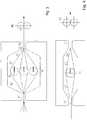
- the Figure 1shows a simple embodiment.
- the spread out fiber bundle with a previously defined number of individual filament layersenters the impregnation chamber 62 through an intake geometry 61 .
- the bundledivides in front of the distributor bar 70 and thus halves its number of filament layers.
- the subsequent melt application through the distributor bar 70takes place between the two partial strands.
- the applicationcan be carried out in the middle, on the upper or on the lower fiber web (see 71 in Figure 5 ). By applying it in the middle, the necessary path for the melt to completely penetrate the fibers (by halving the number of filament layers) is initially halved. Then the two layers come together again to form one layer. In the simple embodiment shown here, this is done without assistance.
- the toolcan also contain an additional geometric design which already supports this merging in the chamber section 63 (first merging area).
- a simple example of thiswould be guide bars or a tool constriction, which bring the layers together (not shown here).
- the consolidation area 64 in the rear part of the impregnation chamberinitiates the transition from the chamber geometry to the later shaping through the nozzle cross-section (see also Figure 6 ). Shaping takes place in the extraction nozzle 65. Due to the narrow cross-section, the matrix material is now pressed through the fiber bed. The tapering that occurred shortly beforehand (depending on the respective end contour of the nozzle) leads to a local pressure increase in the case of a slight excess of melt, which now supports the impregnation effect on all sides.
- the fibersare soaked and consolidated by matrix material from above, below and in the middle. Furthermore, there is a constant relative movement of the individual filaments due to the merging of the bundles, the build-up of pressure and the shaping, which enables complete consolidation.
- the drawn-off profilecan also be calendered by means of a calender 80 for the final shaping.
- the strand obtainedis then either cooled and wound or cut to length; alternatively, it can be processed further immediately, e.g. B. by winding around a core and then cooling (in the case of a thermoplastic matrix) or subsequent curing (in the case of a thermosetting matrix).
- the Figure 4shows how the spread fiber webs can be drawn in separately, in contrast to the Figures 1 to 3 , where the spread fiber webs are drawn in together and contact each other.
- the meltcan be applied through the distributor bar 71 centrally, to the upper or lower fiber web.
- the distributor baris used both as a deflector and as a fiber guide. If the melt is dosed into the space in front of the distributor bar, this supports the impregnation effect by building up local pressure.
- the Figure 7describes the merging of the fiber webs in front of the draw-off nozzle.
- H1 to H2the degree of taper, primarily controllable via the length L1 and the transition radii R1 and R2, an exact pressure profile can be set here. This is for the consolidation process of the product is important, since a slow and controllable pressure build-up without pressure peaks (such as those obtained with a sudden taper) is sought.
- L2is the length of the exhaust nozzle.
- a meltis applied which preferably has a viscosity of 10 mPas to 400 Pas and particularly preferably up to 300 Pas.
- the viscosityis in the lower range down to 10 mPas or even lower.
- the viscosityis generally at least 1 Pas.
- viscosityis understood to mean the resting shear viscosity at the temperature according to the method, measured in a mechanical spectrometer according to ASTM D4400.
- the ratio of fibers to meltis adjusted so that the volume fraction of fibers in the finished part is about 10 to 85%, preferably 15 to 80% and particularly preferably 20 to 75%.
- a resin-hardener systema monomer or a prepolymer is applied as a melt
- the hardening reactiontakes place in the nozzle area and afterwards.
- the nozzle areacan be made longer. Either the appropriate amount of melt is applied or the nozzle acts as a scraper and curing only takes place afterwards.
- the temperature controlmust be selected so that curing can only take place from the nozzle area.
- the productis thermally aftertreated, for example in an oven, after it has been withdrawn from the nozzle.
- the withdrawal speedcan be adjusted as required. It is preferably 0.1 to 30 m / min and particularly preferably 0.5 to 25 m / min.
- the strand obtainedcan have any desired geometry.
- itcan be a film, a tape, a plate, a round profile, a rectangular profile or a complex profile.
- the strand obtainedwhich contains a thermoplastic matrix, becomes long fiber-reinforced rod granules with a length of 4 to 60 mm, preferably 5 to 50 mm, particularly preferably 6 to 40 mm, particularly preferably 5 to 30 mm and very particularly preferably cut 6 to 25 mm.
- Moldingscan then be made from this granulate be produced by injection molding, extrusion, pressing or other common shaping processes, with particularly good properties of the molded part being achieved with gentle processing methods. In this context, gentle means above all that excessive fiber breakage and the associated strong reduction in fiber length are largely avoided.
- the processcan be carried out in different operating modes. This makes it possible to process higher-viscosity systems as matrix material.
- the clear difference to previous solutionsis, according to the invention, the targeted wetting in the strongly expanded state and the subsequent impregnation of the individual fibers by relative movements in the longitudinal and transverse directions. This achieves a very good impregnation quality over a very wide viscosity range, even at a high take-off speed.
Landscapes
- Engineering & Computer Science (AREA)
- Mechanical Engineering (AREA)
- Chemical & Material Sciences (AREA)
- Composite Materials (AREA)
- Reinforced Plastic Materials (AREA)
- Moulding By Coating Moulds (AREA)
- Manufacture Of Alloys Or Alloy Compounds (AREA)
Description
Translated fromGermanGegenstand der Erfindung sind ein Verfahren zur Herstellung von Verbundwerkstoffen, indem ein oder mehrere Faserbündel mit einer Schmelze imprägniert werden können. Durch den speziellen Aufbau ist es möglich, verschiedene Fasermaterialien und Fasertypen, auch mit höherer Tex-Zahl (z. B. Heavy Tows), zu verarbeiten. Die Besonderheit ist die Erzielung einer robusten Einzelfaserimprägnierung in einem sehr weiten Viskositätsbereich. Somit lassen sich entgegen der gängigen Lösungen des Standes der Technik auch höherviskose Systeme verarbeiten.The invention relates to a method for producing composite materials in which one or more fiber bundles can be impregnated with a melt. Due to the special structure, it is possible to process different fiber materials and fiber types, even with a higher Tex number (e.g. heavy tows). The specialty is the achievement of a robust single fiber impregnation in a very wide viscosity range. Thus, contrary to the common solutions of the prior art, systems with a higher viscosity can also be processed.
Die Aufspreizung eines Faserbündels bei der Schmelzeimprägnierung ist bekannt. So wird in der
Eine geringe Matrixviskosität ermöglicht eine höhere Imprägnierwirkung. Je höher die Viskosität, umso schlechter die Imprägnierwirkung. Möglichkeiten, diesen Effekt zu mildern, resultieren in Lösungen mit sehr niedrigen Prozessgeschwindigkeiten oder es werden sehr viele Umlenkpunkte verwendet, die eine hohe Faserschädigung verursachen und ebenfalls den Prozess verlangsamen. Einige technische Lösungen verwenden eine runde Umlenkeinheit mit integrierter Düse für den Matrixauftrag, über welche aufgespreizte Faserrovings einzeln oder als Bahnware gezogen werden. Benetzung und Imprägnierung erfolgen hier in einem Schritt. Für sehr einfache Prozesse oder sehr niedrige Matrixviskositäten kann damit eine ausreichende Imprägnierwirkung erzielt werden. Je nach Rollenanordnung ist die Bahngeschwindigkeit begrenzt, da sonst die Faserschädigung zu stark zunimmt oder aber die Imprägnierung zu schwach ist. Dieser Weg ist Gegenstand etlicher Patentanmeldungen; beispielsweise seien die
Auch in
Die
Demgegenüber besteht die Aufgabe der vorliegenden Erfindung darin, die oben genannten Probleme zu lösen und insbesondere ein Verfahren zur Verfügung zu stellen, bei dem auf einfache Weise ein hoher Imprägnierungsgrad bei geringer Verweilzeit der Schmelze erzielt werden kann, wobei Faserschädigung vermieden und trotzdem eine hohe Abzugsgeschwindigkeit erzielt werden kann. Das Verfahren sollte insbesondere auch bei einer hohen Bandbreite an Fasertypen sowie auch bei höheren Matrixviskositäten zu einer sehr guten Imprägnierqualität führen. Mit sehr guter Imprägnierqualität ist gemeint, dass sehr fein verteilte Einzelfilamentfasern vorliegen, die im Idealfall jede einzeln vollständig mit Matrix umschlossen sind und dass so gut wie keine nicht imprägnierte Filamentbündel oder Filamentnester vorhanden sind. Weiterhin sind auch so gut wie keine Lufteinschlüsse im Produkt vorhanden. Die Imprägnierqualität wird standardmäßig mittels Schliffbildaufnahmen oder REM-Aufnahmen beurteilt.In contrast, the object of the present invention is to solve the above-mentioned problems and in particular to provide a method in which a high degree of impregnation can be achieved in a simple manner with a short residence time of the melt, avoiding fiber damage and still achieving a high take-off speed can be. The method should lead to a very good impregnation quality, especially with a wide range of fiber types and also with higher matrix viscosities. Very good impregnation quality means that there are very finely distributed individual filament fibers which, ideally, are each completely enclosed with matrix and that there are virtually no unimpregnated filament bundles or filament nests. Furthermore, there are virtually no air pockets in the product. The quality of the impregnation is assessed as standard using micrographs or SEM images.
Diese Aufgabe wird durch ein Verfahren zur Herstellung eines Verbundwerkstoffs gelöst, das eine spezielle Kombination von Benetzungstechnik und weiterer Imprägnierung verwirklicht. Das Verfahren enthält folgende Schritte:
- a) Ein oder mehrere Faserbündel werden über eine oder mehrere Spreizvorrichtungen in eine Imprägnierkammer eingezogen, so dass mindestens zwei übereinander liegende, räumlich getrennte und gespreizte Faserbahnen resultieren;
- b) über horizontal ausgerichtete Verteilerbalken, die jeweils zwischen zwei Faserbahnen angeordnet sind, wird Schmelze zugeführt;
- c) die einzelnen Faserbahnen werden so zusammengeführt, dass sie übereinander liegen und einander kontaktieren;
- d) die zusammengeführten Faserbahnen werden am Ende des Werkzeugs durch eine Abzugsdüse gezogen, wobei die erste Formgebung erfolgt.
- a) One or more fiber bundles are drawn into an impregnation chamber via one or more spreading devices, so that at least two superimposed, spatially separated and spread fiber webs result;
- b) melt is fed in via horizontally aligned distributor bars which are each arranged between two fiber webs;
- c) the individual fiber webs are brought together in such a way that they lie on top of one another and contact one another;
- d) the merged fiber webs are pulled through a draw-off nozzle at the end of the tool, the first shaping taking place.
Das Produkt kann anschließend kalandriert und abgekühlt werden.The product can then be calendered and cooled.
Unter "Faserbündel" ist ein Bündel aus einer größeren Zahl von Einzelfilamenten zu verstehen. Üblicherweise sind es mehrere tausend Einzelfilamente. Das Faserbündel kann aus einem Roving oder auch aus einer Mehrzahl an Rovings bestehen; vorzugsweise besteht es aus einem bis maximal 1000 Rovings und besonders bevorzugt aus einem bis maximal 800 Rovings. Diese Rovings werden beim erfindungsgemäßen Verfahren einzeln von Spulen abgewickelt oder abgezogen und vor der Spreizvorrichtung oder am Beginn der Spreizvorrichtung so zusammengeführt, dass sie ein einziges Faserbündel ergeben. Unter "Roving" versteht man hierbei generell ein Bündel von Einzelfilamenten; dieses Bündel kann aus einem einzelnen Fasertyp oder auch aus verschiedenen Fasertypen bestehen. Grundsätzlich sind alle Fasern von ausreichender Länge geeignet; es können anorganische Fasern, Polymerfasern sowie Naturfasern eingesetzt werden. Beispiele geeigneter Fasern sind Metallfasern, Glasfasern (z. B. aus E-Glas, A-Glas, C-Glas, D-Glas, AR-Glas, R-Glas, S1-Glas, S2-Glas usw.), Carbonfasern, metallisierte Carbonfasern, Borfasern, keramische Fasern (z. B. aus Al2O3 oder SiO2), Basaltfasern, Siliciumcarbidfasern, Aramidfasern, Polyamidfasern, Polyethylenfasern, Polyesterfasern (z. B. aus Polybutylenterephthalat), Fasern aus flüssigkristallinem Polyester, Polyacrylnitrilfasern sowie Fasern aus Polyimid, Polyetherimid, Polyphenylensulfid, Polyetherketon, Polyetheretherketon, ferner Cellulosefasern, die mittels des Viskoseverfahrens ersponnen wurden und üblicherweise als Viskosefasern bezeichnet werden, Hanffasern, Flachsfasern, Jutefasern und dergleichen. Der Querschnitt der Fasern kann beispielsweise kreisförmig, rechteckig, oval, elliptisch oder kokonförmig sein. Mit Fasern, deren Querschnitt von der Kreisform abweicht (beispielsweise Flachglasfasern), kann ein höherer Faserfüllgrad im Fertigteil und damit eine höhere Festigkeit erzielt werden.“Fiber bundle” is to be understood as meaning a bundle made up of a large number of individual filaments. Usually there are several thousand individual filaments. The fiber bundle can consist of a roving or a plurality of rovings; it preferably consists of one to a maximum of 1000 rovings and particularly preferably of one to a maximum of 800 rovings. In the method according to the invention, these rovings are individually unwound from spools or pulled off and brought together in front of the spreading device or at the beginning of the spreading device in such a way that they result in a single fiber bundle. "Roving" is understood to mean generally a bundle of single filaments; this bundle can consist of a single type of fiber or also of different types of fibers. In principle, all fibers of sufficient length are suitable; inorganic fibers, polymer fibers and natural fibers can be used. Examples of suitable fibers are metal fibers, glass fibers (e.g. made of E-glass, A-glass, C-glass, D-glass, AR-glass, R-glass, S1-glass, S2-glass, etc.), carbon fibers, metallized carbon fibers, boron fibers, ceramic fibers (e.g. made of Al2 O3 or SiO2 ), basalt fibers, silicon carbide fibers, aramid fibers, polyamide fibers, polyethylene fibers, polyester fibers (e.g. made of polybutylene terephthalate), fibers made of liquid crystalline polyester, polyacrylonitrile fibers and fibers made of polyimide, polyetherimide, polyphenylene sulfide, polyetherketone, polyetheretherketone, and cellulose fibers that have been spun by means of the viscose process and are usually referred to as viscose fibers, hemp fibers, flax fibers, jute fibers and the like. The cross-section of the fibers can be circular, rectangular, oval, elliptical or cocoon-shaped, for example. With fibers whose cross-section deviates from the circular shape (for example flat glass fibers), a higher degree of fiber filling in the finished part and thus higher strength can be achieved.
Das Faserbündel wird aufgeweitet und so geführt, dass spätestens beim Schmelzeauftrag mindestens zwei übereinanderliegende Bahnen resultieren. Die Bahnseparation kann im Werkzeug oder auch schon vor dem Werkzeug erfolgen.The fiber bundle is widened and guided in such a way that at the latest when the melt is applied, at least two superimposed webs result. The path separation can take place in the tool or even before the tool.
In einer bevorzugten Ausführungsform werden mindestens zwei Faserbündel jeweils separat über eine Spreizvorrichtung aufgeweitet und durch separate Öffnungen in eine Imprägnierkammer eingezogen. Damit erhält man direkt zwei räumlich getrennte Faserbahnen.In a preferred embodiment, at least two fiber bundles are each expanded separately via a spreading device and drawn into an impregnation chamber through separate openings. This gives you two spatially separate fiber webs.
Zweckmäßigerweise sind die Faserbündel, die Spreizvorrichtungen und die Einzugsöffnungen hierbei übereinander angeordnet, so dass die Faserbahnen nicht umgelenkt werden müssen. In Sonderfällen können die Faserbündel, die Spreizvorrichtungen und die Einzugsöffnungen jedoch auch anders angeordnet sein, so dass die Faserbahnen in die passende Lage umgelenkt werden.The fiber bundles, the spreading devices and the intake openings are expediently arranged one above the other, so that the fiber webs do not have to be deflected. In special cases, however, the fiber bundles, the spreading devices and the intake openings can also be arranged differently, so that the fiber webs are deflected into the appropriate position.
In einer weiteren bevorzugten Ausführungsform werden mindestens zwei Faserbündel jeweils separat über eine Spreizvorrichtung aufgeweitet und durch eine gemeinsame Öffnung in eine Imprägnierkammer eingezogen. Beim Eintreten in die Imprägnierkammer teilen sich die einzelnen Faserbahnen wieder auf. Die Teilung der vorher separierten Bahnen kann durch manuelles Einfädeln im geöffneten Werkzeug erfolgen. Von daher ist ein einfach zu öffnendes, mindestens zweigeteiltes Werkzeug zu bevorzugen.In a further preferred embodiment, at least two fiber bundles are each expanded separately via a spreading device and drawn into an impregnation chamber through a common opening. When entering the impregnation chamber, the individual fiber webs divide up again. The previously separated tracks can be divided by manually threading them into the open tool. For this reason, an easy-to-open tool with at least two parts is to be preferred.
In einer weiteren Ausführungsform wird ein Faserbündel über eine Spreizvorrichtung aufgeweitet und hierbei oder anschließend durch eine geeignete Vorrichtung in mehrere übereinander liegende, räumlich getrennte und gespreizte Faserbahnen separiert. Allerdings müssen die separierten Faserbahnen hierbei umgelenkt werden. Anschließend werden die Faserbahnen in eine Imprägnierkammer eingezogen. In einer Variante hiervon werden zwei oder mehr Faserbündel jeweils separat über eine Spreizvorrichtung aufgeweitet und hierbei oder anschließend durch eine geeignete Vorrichtung jeweils in mehrere übereinander liegende, räumlich getrennte und gespreizte Faserbahnen separiert, diese umgelenkt und anschließend in eine Imprägnierkammer eingezogen.In a further embodiment, a fiber bundle is expanded by means of a spreading device and, here or subsequently, separated by a suitable device into several superimposed, spatially separated and spread fiber webs. However, the separated fiber webs have to be deflected here. The fiber webs are then drawn into an impregnation chamber. In a variant of this, two or more Fiber bundles each expanded separately via a spreading device and separated here or subsequently by a suitable device into several superimposed, spatially separated and spread fiber webs, these are deflected and then drawn into an impregnation chamber.
Im Rahmen der Erfindung sind auch beliebige Kombinationen dieser verschiedenen Ausführungsformen möglich.Any combinations of these different embodiments are also possible within the scope of the invention.
Die Aufspreizung im Verfahrensschritt a) ist abhängig von der Geometrie des Endprodukts. Wenn das Endprodukt ein Tape ist, wird das Faserbündel um einen vergleichsweise hohen Faktor aufgespreizt. Wenn das Endprodukt dagegen relativ dick ist, beispielsweise einen rechteckigen oder quadratischen Querschnitt hat, kann das Faserbündel bezogen auf die Breite des Endprodukts um einen vergleichsweise niedrigen Faktor aufgespreizt werden, so dass keine sinnvolle allgemeingültige Obergrenze angegeben werden kann. Je nach Geometrie des Endprodukts kann eine Aufspreizung vorzugsweise maximal um den Faktor 30, besonders bevorzugt maximal um den Faktor 20, insbesondere bevorzugt maximal um den Faktor 14 und ganz besonders bevorzugt maximal um den Faktor 8 erfolgen, jeweils bezogen auf die ursprüngliche Breite des Faserbündels. Insbesondere bei relativ dicken Endprodukten kann es sinnvoll sein, mehr als zwei übereinander liegende Bahnen zusammenzuführen.The spreading in process step a) depends on the geometry of the end product. If the end product is a tape, the fiber bundle is spread apart by a comparatively high factor. If, on the other hand, the end product is relatively thick, for example has a rectangular or square cross-section, the fiber bundle can be spread out by a comparatively low factor based on the width of the end product, so that no meaningful general upper limit can be specified. Depending on the geometry of the end product, expansion can preferably take place by a maximum of 30, particularly preferably a maximum of 20, particularly preferably a maximum of 14 and very particularly preferably a maximum of 8, each based on the original width of the fiber bundle. In the case of relatively thick end products in particular, it can be useful to merge more than two webs lying one above the other.
Hierbei ist es bevorzugt, dass die Faserbündel so weit aufgespreizt sind, dass ihre mittlere Dicke dem 1- bis 50-fachen Filamentdurchmesser, besonders bevorzugt dem 1- bis 40-fachen Filamentdurchmesser, insbesondere bevorzugt dem 1,5- bis 35-fachen Filamentdurchmesser und ganz besonders bevorzugt dem 1,8- bis 30-fachen Filamentdurchmesser entspricht. Die Mittelung erfolgt hierbei über die Breite der Faserbahn hinweg. Bei Fasern mit nicht kreisförmigem Querschnitt wird als Filamentdurchmesser die kürzeste Querschnittsachse gewählt. Hinsichtlich des Faserquerschnitts kann den Angaben des Faserherstellers gefolgt werden. Bei einer Mischung verschiedener Fasern wird als Filamentdurchmesser das arithmetische Mittel bezogen auf die Zahl der Einzelfilamente gewählt. Wenn Herstellerangaben nicht verfügbar sind oder bei Fasern gleicher Art mit unterschiedlicher Geometrie, etwa Naturfasern, wird der mittlere Filamentdurchmesser durch eine rasterelektronenmikroskopische Aufnahme (REM-Aufnahme), Ausmessen und Berechnen des arithmetischen Mittels bezogen auf die Zahl der Einzelfilamente bestimmt.It is preferred here that the fiber bundles are spread so far that their mean thickness is 1 to 50 times the filament diameter, particularly preferably 1 to 40 times the filament diameter, particularly preferably 1.5 to 35 times the filament diameter and very particularly preferably 1.8 to 30 times the filament diameter. The averaging takes place over the width of the fiber web. In the case of fibers with a non-circular cross-section, the shortest cross-sectional axis is selected as the filament diameter. With regard to the fiber cross-section, the information provided by the fiber manufacturer can be followed. If different fibers are mixed, the filament diameter chosen is the arithmetic mean based on the number of individual filaments. If manufacturer information is not available or if fibers of the same type with different geometry, e.g. natural fibers, the mean filament diameter is determined by a scanning electron microscope image (SEM image), measuring and calculating the arithmetic mean based on the number of individual filaments.
Dem Fachmann sind geeignete Spreizvorrichtungen zum Aufspreizen des oder der Faserbündel bekannt. Beispielsweise verwendet man hierfür mindestens eine Umlenkstange. In der Praxis sind mehrere, etwa zwei, drei oder vier Umlenkstangen hintereinander angeordnet.Suitable spreading devices for spreading the fiber bundle or bundles are known to those skilled in the art. For example, at least one deflection rod is used for this. In practice, several, for example two, three or four deflection rods are arranged one behind the other.
Die Matrix des Verbundwerkstoffs kann eine thermoplastische Formmasse, ein Duroplast, ein Thermoplast-Duroplast-Hybridsystem, ein thermoplastisches Elastomer oder ein vernetztes Elastomer sein. Thermoplastische Formmassen bestehen aus einem Thermoplasten als Hauptbestandteil oder alleinigem Bestandteil. Weitere Bestandteile können beispielsweise Stabilisatoren, Verarbeitungshilfsmittel, Pigmente, Flammschutzmittel, andere Thermoplaste als Blendkomponenten, Schlagzähmodifier oder dergleichen sein. Geeignete Thermoplaste sind beispielsweise Polyolefine (wie Polyethylen oder Polypropylen), Polyester (wie Polyethylenterephthalat, Polybutylenterephthalat, Polyarylate oder flüssigkristalline Polyester), Polycarbonat, Polyestercarbonat, Polyamide (wie PA46, PA6, PA66, PA610, PA612, PA1010, PA11, PA12, teilaromatische Polyamide (PPA) oder transparente Polyamide beispielsweise auf Basis von linearen oder verzweigten aliphatischen, cycloaliphatischen oder aromatischen Dicarbonsäuren und Diaminen), Polyarylenetherketone (wie Polyetheretherketon, Polyetherketon oder Polyetheretherketonketon), Polyphenylensulfid, Polyetherimid, Polymethylmethacrylat, Polystyrol, Styrol-Acrylnitril-Copolymere (SAN), Styrol-Acrylnitril-Butadien-Copolymere (ABS), Polyacetal, Polyurethan, Polyimid, Polysulfon, Polyethersulfon, Polyphenylenoxid oder Fluorpolymere (wie PVDF oder ETFE). Der Thermoplast wird üblicherweise als Schmelze aufgebracht. Diese Schmelze kann auch ein Lösungsmittel enthalten, das anschließend wieder entfernt wird. Es kann aber auch stattdessen ein Monomer als Schmelze aufgebracht werden, das dann in situ polymerisiert wird; so kann beispielsweise eine Polyamidmatrix durch anionische Lactampolymerisation erzeugt werden. Eine weitere Variante besteht darin, dass ein Polymer mit vergleichsweise niedrigem Molekulargewicht zusammen mit einem Kopplungsmittel als Schmelze aufgebracht wird und dann während des Imprägniervorgangs und insbesondere danach eine Kettenverlängerung durchgeführt wird.The matrix of the composite material can be a thermoplastic molding compound, a thermoset, a thermoplastic-thermoset hybrid system, a thermoplastic elastomer or a cross-linked elastomer. Thermoplastic molding compounds consist of a thermoplastic as the main component or the sole component. Further components can for example Stabilizers, processing aids, pigments, flame retardants, thermoplastics other than blend components, impact modifiers or the like. Suitable thermoplastics are, for example, polyolefins (such as polyethylene or polypropylene), polyesters (such as polyethylene terephthalate, polybutylene terephthalate, polyarylates or liquid crystalline polyesters), polycarbonate, polyester carbonate, polyamides (such as PA46, PA6, PA66, PA610, PA612, PA1010, PA11, PA12, partially aromatic polyamides (PPA) or transparent polyamides, for example based on linear or branched aliphatic, cycloaliphatic or aromatic dicarboxylic acids and diamines), polyarylene ether ketones (such as polyether ether ketone, polyether ketone or polyether ether ketone ketone), polyphenylene sulfide, polyether imide, polymethyl methacrylate, polystyrene, styrene-acrylate, polystyrene, styrene-acrylate Styrene-acrylonitrile-butadiene copolymers (ABS), polyacetal, polyurethane, polyimide, polysulfone, polyether sulfone, polyphenylene oxide or fluoropolymers (such as PVDF or ETFE). The thermoplastic is usually applied as a melt. This melt can also contain a solvent, which is then removed again. Instead, however, a monomer can also be applied as a melt, which is then polymerized in situ; For example, a polyamide matrix can be produced by anionic lactam polymerization. Another variant consists in applying a polymer with a comparatively low molecular weight together with a coupling agent as a melt and then carrying out a chain extension during the impregnation process and in particular afterwards.
Geeignete Duroplaste sind beispielsweise ungesättigte Polyesterharze, Epoxidharze, Aminoplaste, Phenoplaste, vernetzte Polyacrylate, Polyurethane, Melaminharze, Vinylesterharze oder Bismaleinimidharze. Die im Verfahrensschritt b) aufgetragene Schmelze ist in diesem Fall ein harz-Härter-Gemisch oder eine sonstige geeignete Vorstufe, etwa ein Präpolymer.Suitable thermosets are, for example, unsaturated polyester resins, epoxy resins, aminoplasts, phenoplasts, crosslinked polyacrylates, polyurethanes, melamine resins, vinyl ester resins or bismaleimide resins. The melt applied in process step b) is in this case a resin-hardener mixture or another suitable precursor, such as a prepolymer.
Geeignete thermoplastische Elastomere sind beispielsweise TPE-O (thermoplastische Elastomere auf Olefinbasis, etwa PP/EPDM), TPE-V (vernetzte thermoplastische Elastomere auf Olefinbasis, insbesondere PP/vernetztes EPDM), TPE-U (thermoplastische Elastomere auf Polyurethanbasis), TPE-E (thermoplastische Polyesterelastomere), TPE-S (Styrolblockcopolymere, etwa SBS, SEBS, SEPS, SEEPS oder MBS) sowie TPE-A (Polyamidelastomere).Suitable thermoplastic elastomers are, for example, TPE-O (thermoplastic elastomers based on olefins, e.g. PP / EPDM), TPE-V (crosslinked thermoplastic elastomers based on olefin, in particular PP / crosslinked EPDM), TPE-U (thermoplastic elastomers based on polyurethane), TPE-E (thermoplastic polyester elastomers), TPE-S (styrene block copolymers such as SBS, SEBS, SEPS, SEEPS or MBS) and TPE-A (polyamide elastomers).
Geeignete vernetzte Elastomere werden aus einem Kautschukcompound erhalten, das dem Stand der Technik entsprechend ein Vulkanisationsmittel sowie gegebenenfalls Vulkanisationshilfsmittel, Füllstoffe, Öle sowie weitere übliche Zusätze enthält. Beispiele derartiger Elastomere sind EPDM, Styrol/Butadien-Kautschuk, Butylkautschuk, Silikonkautschuk, Epoxidkautschuk, Chloroprenkautschuk, Acrylkautschuk und dergleichen.Suitable crosslinked elastomers are obtained from a rubber compound which, in accordance with the state of the art, contains a vulcanizing agent and optionally vulcanizing auxiliaries, fillers, oils and other customary additives. Examples of such elastomers are EPDM, styrene / butadiene rubber, butyl rubber, silicone rubber, epoxy rubber, chloroprene rubber, acrylic rubber and the like.
Im Rahmen der Erfindung wird der Begriff "Schmelze" für alle, beispielsweise obengenannten, fließfähigen Materialien verwendet, die auf die Faserbündel aufgebracht werden und dann die Matrix ergeben.In the context of the invention, the term “melt” is used for all, for example above-mentioned, flowable materials which are applied to the fiber bundles and then result in the matrix.
Im Verfahrensschritt a) werden mehrere Faserbahnen mit einem sehr geringen Höhenaufbau erzeugt. Ziel ist eine deutliche Reduzierung des Flächengewichts. Das genaue Flächengewicht sowie die Anzahl der Bahnen hängt von dem später gewünschten Produktaufbau und dem verwendeten Matrixmaterial beziehungsweise der Viskosität der Schmelze ab. Vorzugsweise entspricht die Bahnbreite entweder der späteren Produktbreite oder es kann eine höhere Aufspreizung erfolgen, um den Benetzungsvorgang weiter zu erleichtern. Die Faserbahnen laufen zusammen über einen gemeinsamen Einzug oder separat in die Imprägnierkammer ein.In process step a), several fiber webs with a very low build-up in height are produced. The aim is to significantly reduce the weight per unit area. The exact weight per unit area and the number of lanes depends on the later desired product structure and the matrix material used or the viscosity of the melt. Preferably, the web width either corresponds to the later product width or a greater spread can take place in order to further facilitate the wetting process. The fiber webs enter the impregnation chamber together via a common intake or separately.
Der Benetzungsvorgang erfolgt nun zwischen den jeweiligen Faserbahnen, wo ein Verteilerquerschnitt den Schmelzeanteil einbringt. Abhängig von den später gewünschten Produkteigenschaften sowie den verwendeten Ausgangsmaterialien können ein oder mehrere Schmelzeverteiler angeordnet werden, die vorzugsweise übereinander angebracht sind. Ein Verteilerbalken wird von einem Extruder oder einer Schmelzepumpe, die einer Plastifiziereinheit nachgeschaltet ist, mit Schmelze versorgt und dosiert das Polymer gleichmäßig über den Bahnquerschnitt. Die gleichmäßige Dosierung erfolgt über den Innenquerschnitt der Auftragsdüse. Die Geometrie der Verteilerdüse sorgt für einen gleichmäßigen Auftrag der Schmelze, indem vorzugsweise über die gesamte Breite der Faserbahnen eine Düsenöffnung oder mehrere nebeneinander angebrachte Düsenöffnungen vorhanden sind. Hier kann ein Bügelverteiler angebracht sein, eine Quellflussverteilergeometrie oder ähnliche Formen, die eine gezielte Dosierung sowie einen gleichmäßigen Auftrag des Schmelzefilms ermöglichen. Solche Verteilerdüsen sind dem Fachmann bekannt. Eine geeignete Quellflussverteilergeometrie ist beispielsweise in der
Im Rahmen der Erfindung kann zusätzlich weitere Schmelze durch eine oder zwei Auftragsdüsen aufgebracht werden, wobei entweder eine Auftragsdüse oberhalb der obersten Faserbahn, eine Auftragsdüse unterhalb der untersten Faserbahn oder jeweils eine Auftragsdüse oberhalb der obersten Faserbahn und unterhalb der untersten Faserbahn angeordnet ist.Within the scope of the invention, additional melt can also be applied through one or two application nozzles, with either an application nozzle above the top fiber web, an application nozzle below the bottom fiber web or an application nozzle each above the top fiber web and below the bottom fiber web.
Im folgenden Impägnierschritt werden die verschiedenen Bahnen zusammengeführt und durch eine Düse gezogen. Der Kammerbereich zwischen Schmelzeauftrag und Düse kann zur Unterstützung mit einem leichten Schmelzeüberschuss versehen sein. In diesem Bereich legen sich die Faserbahnen zusammen und die aufgebrachte Schmelze dringt in die noch nicht imprägnierten Faserzwischenräume ein. Unterstützt wird dieser Vorgang durch lokale Differenzdrücke, die durch die Zusammenführung im Düsenbereich entstehen können. Die Zusammenführung kann auch im Kammerbereich durch die Kammergeometrie oder durch einen eingebrachten Einsatz in Form einer Querschnittsverjüngung unterstützt werden. In diesem Fall werden die Fasern schon in einer Vorstufe mit Schmelze vorkonsolidiert, die Düse übernimmt dann die restliche Konsolidierung. Wenn das Endprodukt eine Folie ist, wird eher keine Querschnittsverjüngung benötigt; ist es ein Profil, wird der Querschnitt dagegen von einer aufgeweiteten Faserbahn zur Profilform reduziert.In the following impregnation step, the different webs are brought together and drawn through a nozzle. The chamber area between the melt application and the nozzle can be provided with a slight excess of melt for support. In this area the fiber webs collapse and the applied melt penetrates into the not yet impregnated fiber gaps. This process is supported by local differential pressures that can arise as a result of the convergence in the nozzle area. The merging can also be supported in the chamber area by the chamber geometry or by an inserted insert in the form of a cross-sectional taper. In this case, the fibers are pre-consolidated with melt in a preliminary stage, and the nozzle then takes over the remaining consolidation. If the end product is a film, it will not be Cross-sectional tapering required; if it is a profile, on the other hand, the cross-section is reduced from a widened fiber web to a profile shape.
Die Abzugsdüse übernimmt die erste Formgebung und bewirkt eine weitere Imprägnierung der Bahnware. Sie enthält in der Regel keine integrierte Abzugseinrichtung. Der Strang wird üblicherweise vielmehr durch einen direkt nach der Düse angebrachten Abzug oder durch Kalanderwalzen gezogen. Ein derartiger Abzug, beispielsweise in Form von Rollen oder Walzen, sowie Kalander sind Stand der Technik. Hierdurch kann eine weitere Formgebung erfolgen.The draw-off nozzle takes on the initial shaping and effects a further impregnation of the web material. As a rule, it does not contain an integrated extraction device. Rather, the strand is usually drawn through a take-off device attached directly after the nozzle or through calender rolls. Such a take-off, for example in the form of rolls or cylinders, and calenders are state of the art. This allows a further shaping to take place.
In der
In der
In der
Die
Die
In der
Die
Die
In der
In der
Die
In der
In der
Die
Beim erfindungsgemäßen Verfahren wird eine Schmelze aufgetragen, die vorzugsweise eine Viskosität von 10 mPas bis 400 Pas und besonders bevorzugt bis 300 Pas besitzt. Bei Präpolymeren bzw. Harz-Härter-Systemen, die nach Härtung Duroplaste oder Thermoplast-Duroplast-Hybridsystemen ergeben, liegt die Viskosität dabei im unteren Bereich bis hinab zu 10 mPas oder noch tiefer. Bei einer Schmelze aus einer thermoplastischen Formmasse, einem thermoplastischen Elastomer oder einem Elastomercompound beträgt die Viskosität in der Regel mindestens 1 Pas. Unter Viskosität wird erfindungsgemäß die Ruhe-Scherviskosität bei der verfahrensgemäßen Temperatur verstanden, gemessen in einem mechanischen Spektrometer nach ASTM D4400.In the method according to the invention, a melt is applied which preferably has a viscosity of 10 mPas to 400 Pas and particularly preferably up to 300 Pas. In the case of prepolymers or resin-hardener systems which, after curing, result in thermosets or thermoplastic-thermoset hybrid systems, the viscosity is in the lower range down to 10 mPas or even lower. In the case of a melt composed of a thermoplastic molding compound, a thermoplastic elastomer or an elastomer compound, the viscosity is generally at least 1 Pas. According to the invention, viscosity is understood to mean the resting shear viscosity at the temperature according to the method, measured in a mechanical spectrometer according to ASTM D4400.
Beim Auftragen der Schmelze wird in der Regel ohne Schmelzeüberschuss, insbesondere bei höherviskosen Schmelzen, oder mit nur geringem Schmelzeüberschuss gearbeitet. Beim Arbeiten mit Schmelzeüberschuss baut sich der Überschuss im Bereich zur Düse auf und bildet ein Schmelzebad. Hier muss Vorsorge getroffen werden, dass die überschüssige Schmelze durch eine dafür vorgesehene Öffnung abfließen kann. Das Verhältnis von Fasern zu Schmelze wird so eingestellt, dass der Volumenanteil der Fasern im Fertigteil etwa 10 bis 85 %, bevorzugt 15 bis 80 % und besonders bevorzugt 20 bis 75 % beträgt.When the melt is applied, work is generally carried out without excess melt, in particular in the case of melts with a higher viscosity, or with only a slight excess of melt. When working with excess melt, the excess builds up in the area of the nozzle and forms a melt pool. Here precautions must be taken to ensure that the excess melt can flow off through an opening provided for this purpose. The ratio of fibers to melt is adjusted so that the volume fraction of fibers in the finished part is about 10 to 85%, preferably 15 to 80% and particularly preferably 20 to 75%.
Wenn als Schmelze ein Harz-Härter-System, ein Monomer oder ein Präpolymer aufgetragen wird, findet die Aushärtereaktion im Düsenbereich sowie danach statt. Der Düsenbereich kann hierbei länger ausgeführt sein. Es wird entweder mit mengenmäßig passendem Schmelzeauftrag gearbeitet oder die Düse wirkt als Abstreifer und die Aushärtung erfolgt erst anschließend. Die Temperaturführung muss so gewählt werden, dass die Aushärtung erst ab dem Düsenbereich stattfinden kann. Zur Vervollständigung der Aushärtung wird das Produkt nach dem Abziehen von der Düse gegebenenfalls thermisch nachbehandelt, beispielsweise in einem Ofen.If a resin-hardener system, a monomer or a prepolymer is applied as a melt, the hardening reaction takes place in the nozzle area and afterwards. The nozzle area can be made longer. Either the appropriate amount of melt is applied or the nozzle acts as a scraper and curing only takes place afterwards. The temperature control must be selected so that curing can only take place from the nozzle area. To complete the hardening process, the product is thermally aftertreated, for example in an oven, after it has been withdrawn from the nozzle.
Die Abzugsgeschwindigkeit ist nach Bedarf einstellbar. Sie liegt vorzugsweise bei 0,1 bis 30 m/min und besonders bevorzugt bei 0,5 bis 25 m/min.The withdrawal speed can be adjusted as required. It is preferably 0.1 to 30 m / min and particularly preferably 0.5 to 25 m / min.
Beim erfindungsgemäßen Verfahren kann der erhaltene Strang jede gewünschte Geometrie besitzen. Er kann beispielsweise eine Folie, ein Tape, eine Platte, ein Rundprofil, ein Rechteckprofil oder ein komplexes Profil sein.In the process according to the invention, the strand obtained can have any desired geometry. For example, it can be a film, a tape, a plate, a round profile, a rectangular profile or a complex profile.
In einer Variante dieses Verfahrens wird der erhaltene Strang, der eine thermoplastische Matrix enthält, zu langfaserverstärktem Stäbchengranulat mit einer Länge von 4 bis 60 mm, vorzugsweise 5 bis 50 mm, besonders bevorzugt 6 bis 40 mm, insbesondere bevorzugt 5 bis 30 mm und ganz besonders bevorzugt 6 bis 25 mm geschnitten. Aus diesem Granulat können dann Formteile mittels Spritzgießen, Extrusion, Pressen oder anderer gebräuchlicher Formgebungsverfahren hergestellt werden, wobei besonders gute Eigenschaften des Formteils mit schonenden Verarbeitungsverfahren erreicht werden. In diesem Zusammenhang bedeutet schonend vor allem, dass ein übermäßiger Faserbruch und die damit einhergehende starke Reduktion der Faserlänge weitgehend vermieden wird. Beim Spritzguss bedeutet dies, dass bevorzugt Schnecken mit großem Durchmesser und tiefem Kompressionsverhältnis sowie großzügig dimensionierte Düsen- und Angusskanäle zum Einsatz kommen. Ergänzend sollte dafür gesorgt werden, dass die Stäbchengranulate mit Hilfe von hohen Zylindertemperaturen rasch aufschmelzen (Kontakterwärmung) und die Fasern nicht durch übermäßige Scherbeanspruchung zu stark zerkleinert werden. Unter Berücksichtigung dieser Maßnahmen werden Formteile erhalten, die im Mittel eine höhere Faserlänge aufweisen als vergleichbare Formteile hergestellt aus kurzfaserverstärkten Formmassen. Hierdurch wird eine deutliche Verbesserung der Eigenschaften, insbesondere beim Zug-E-Modul, der Reißfestigkeit und der Kerbschlagzähigkeit erreicht.In a variant of this process, the strand obtained, which contains a thermoplastic matrix, becomes long fiber-reinforced rod granules with a length of 4 to 60 mm, preferably 5 to 50 mm, particularly preferably 6 to 40 mm, particularly preferably 5 to 30 mm and very particularly preferably cut 6 to 25 mm. Moldings can then be made from this granulate be produced by injection molding, extrusion, pressing or other common shaping processes, with particularly good properties of the molded part being achieved with gentle processing methods. In this context, gentle means above all that excessive fiber breakage and the associated strong reduction in fiber length are largely avoided. In the case of injection molding, this means that screws with a large diameter and low compression ratio as well as generously dimensioned nozzle and sprue channels are preferred. In addition, care should be taken to ensure that the stick granules melt quickly with the help of high cylinder temperatures (contact heating) and that the fibers are not crushed too much by excessive shear stress. Taking these measures into account, molded parts are obtained which, on average, have a longer fiber length than comparable molded parts made from short-fiber-reinforced molding compounds. This results in a significant improvement in the properties, in particular in the tensile modulus of elasticity, the tear strength and the notched impact strength.
Abhängig von der Schmelzeviskosität und der Filamentlagenanzahl kann das Verfahren in unterschiedlichen Betriebsweisen durchgeführt werden. Dadurch ist es möglich, auch höherviskose Systeme als Matrixmaterial zu verarbeiten. Der deutliche Unterschied zu bisherigen Lösungen ist erfindungsgemäß die gezielte Benetzung im stark aufgespreizten Zustand und die anschließende Imprägnierung der Einzelfasern durch Relativbewegungen in Längs- und Querrichtung. Damit wird eine sehr gute Imprägnierqualität über einen sehr weiten Viskositätsbereich hinweg erzielt, auch bei hoher Abzugsgeschwindigkeit.Depending on the melt viscosity and the number of filament layers, the process can be carried out in different operating modes. This makes it possible to process higher-viscosity systems as matrix material. The clear difference to previous solutions is, according to the invention, the targeted wetting in the strongly expanded state and the subsequent impregnation of the individual fibers by relative movements in the longitudinal and transverse directions. This achieves a very good impregnation quality over a very wide viscosity range, even at a high take-off speed.
- 6161
- EinzugsbereichCatchment area
- 6262
- ImprägnierkammerImpregnation chamber
- 6363
- erster Zusammenführungsbereichfirst merging area
- 6464
- KonsolidierungsbereichConsolidation area
- 6565
- AbzugsdüseExhaust nozzle
- 7070
- VerteilerbalkenManifold
- 7171
- schwenkbarer Verteilerbalkenswiveling distributor bar
- 7272
- Geometrievariante eines VerteilerbalkensGeometrical variant of a distributor bar
- 7373
- Geometrievariante eines VerteilerbalkensGeometrical variant of a distributor bar
- 7474
- Geometrievariante eines VerteilerbalkensGeometrical variant of a distributor bar
- 8080
- Kalandercalender
Claims (9)
- Method for producing a fibre composite material, which includes the following steps:a) one or more fibre bundles are drawn over one or more spreading devices into an impregnation chamber (62), so that at least two physically separated and spread fibre webs located above one another result;b) melt is supplied via horizontally aligned distributor beams (70), which are each arranged between two fibre webs;c) the individual fibre webs are led together such that they lie above one another and contact one another;d) the fibre webs led together are drawn through a take-off die (65) at the end of the tool, the first shaping being carried out.
- Method according to Claim 1,characterized in that in step a) at least two fibre bundles are each widened separately over a spreading device and drawn into an impregnation chamber through separate openings.
- Method according to Claim 1,characterized in that in step a) at least two fibre bundles are each widened separately over a spreading device and drawn into an impregnation chamber through a common opening.
- Method according to Claim 1,characterized in that in step a) a fibre bundle is widened over a spreading device and, here or hereafter, is separated by a suitable device into multiple physically separated and spread fibre webs located one above another.
- Method according to one of the preceding claims,characterized in that the matrix of the composite material is a thermoplastic moulding compound, a thermosetting plastic, a thermoplastic-thermosetting hybrid system, a thermoplastic elastomer or a cross-linked elastomer.
- Method according to one of the preceding claims,characterized in that in step a) the fibre layer is spread so widely that its average thickness corresponds to 1 to 50 times the filament diameter.
- Method according to one of the preceding claims,characterized in that the strand obtained is calendered after leaving the take-off die (65).
- Method according to one of the preceding claims,characterized in that the strand obtained is cut to form long-fibre reinforced rod-shaped pellets with a length of 4 to 60 mm.
- Method according to one of Claims 1 to 7,characterized in that the strand obtained is a thin sheet, a tape, a board, a round profile, a rectangular profile or a complex profile.
Applications Claiming Priority (2)
| Application Number | Priority Date | Filing Date | Title |
|---|---|---|---|
| EP15162335 | 2015-04-02 | ||
| PCT/EP2016/056585WO2016156222A1 (en) | 2015-04-02 | 2016-03-24 | Method and device for producing a fibre composite material |
Publications (2)
| Publication Number | Publication Date |
|---|---|
| EP3277473A1 EP3277473A1 (en) | 2018-02-07 |
| EP3277473B1true EP3277473B1 (en) | 2021-03-24 |
Family
ID=52946304
Family Applications (1)
| Application Number | Title | Priority Date | Filing Date |
|---|---|---|---|
| EP16714810.5AActiveEP3277473B1 (en) | 2015-04-02 | 2016-03-24 | Method for producing a fibre composite material |
Country Status (9)
| Country | Link |
|---|---|
| US (1) | US10836136B2 (en) |
| EP (1) | EP3277473B1 (en) |
| JP (1) | JP6890547B2 (en) |
| KR (1) | KR102338004B1 (en) |
| CN (1) | CN107405798B (en) |
| BR (1) | BR112017021124B1 (en) |
| CA (1) | CA2980235C (en) |
| MX (1) | MX384926B (en) |
| WO (1) | WO2016156222A1 (en) |
Families Citing this family (8)
| Publication number | Priority date | Publication date | Assignee | Title |
|---|---|---|---|---|
| US20200031021A1 (en)* | 2017-02-13 | 2020-01-30 | Sabic Global Technologies B.V. | Method for producing fiber tape |
| FR3068286B1 (en)* | 2017-06-30 | 2020-12-11 | Centre Techn Ind Mecanique | INSTALLATION AND PROCESS FOR PULTRUSION OF COMPOSITE STRIP MATERIAL |
| WO2019060146A1 (en) | 2017-09-22 | 2019-03-28 | Sabic Global Technologies B.V. | Process for the manufacture of flame retardant polycarbonate particles and flame retardant polycarbonate particles prepared thereby |
| EP4368364A3 (en)* | 2018-03-06 | 2024-08-14 | Aerlyte, Inc. | Fiber-reinforced composites and methods of forming and using same |
| EP3626764B1 (en) | 2018-09-21 | 2021-02-24 | Evonik Operations GmbH | Composite with thermoplastic matrix |
| EP4111010A1 (en)* | 2020-02-26 | 2023-01-04 | Owens Corning Intellectual Capital, LLC | Composite parts with improved modulus |
| CN112549586B (en)* | 2020-11-11 | 2022-12-27 | 青岛海力威新材料科技股份有限公司 | Static infiltration device for rapid pultrusion of composite material |
| JP7751821B2 (en)* | 2022-09-30 | 2025-10-09 | 福井県 | Thermoplastic resin prepreg sheet manufacturing method and manufacturing device |
Family Cites Families (35)
| Publication number | Priority date | Publication date | Assignee | Title |
|---|---|---|---|---|
| FR1306675A (en) | 1961-09-04 | 1962-10-19 | Chausson Usines Sa | Device for coating and impregnating flexible sheets |
| US3415920A (en)* | 1965-08-19 | 1968-12-10 | Dow Chemical Co | Multilayer extrusion process |
| US3503371A (en)* | 1968-04-09 | 1970-03-31 | Hercules Inc | Roving impregnator for making low-void filament wound articles |
| US3959431A (en)* | 1972-09-08 | 1976-05-25 | Welex, Incorporated | Method and apparatus for making multiple-layered sheets |
| US4059068A (en) | 1974-06-10 | 1977-11-22 | Rhone-Poulenc-Textile | Apparatus for treating filamentary products |
| US4164439A (en)* | 1978-03-23 | 1979-08-14 | Fibergate Corporation | Apparatus for fabricating continuous fiber reinforced plastic grating articles |
| EP0056703B2 (en) | 1981-01-21 | 1992-05-27 | Imperial Chemical Industries Plc | Fibre-reinforced compositions and methods for producing such compositions |
| GB8822520D0 (en) | 1988-09-26 | 1988-11-02 | Tech Textiles Ltd | Process for continuously forming reinforced plastics articles |
| FI83490C (en) | 1989-05-10 | 1991-07-25 | Neste Oy | Method and apparatus for making a fiber-reinforced material |
| FI91373C (en) | 1989-07-14 | 1994-06-27 | Neste Oy | Method and apparatus for impregnating a continuous fiber bundle |
| DE3934091A1 (en) | 1989-10-12 | 1991-04-18 | Huels Chemische Werke Ag | COMPONENTS OF FIBER-REINFORCED POLYAMIDE MOLDINGS AND RUBBER AND METHOD FOR THE PRODUCTION THEREOF |
| DE3935169A1 (en) | 1989-10-21 | 1991-04-25 | Huels Chemische Werke Ag | FIBER REINFORCED POLYPHENYLENE ETHER MOLDS AND METHOD FOR THEIR PRODUCTION |
| DE4009917C1 (en) | 1990-03-28 | 1991-11-21 | Paul Troester Maschinenfabrik, 3000 Hannover, De | |
| US5054705A (en) | 1990-05-04 | 1991-10-08 | Owens-Corning Fiberglas Corporation | Reciprocating strand guide for split strand roving packages |
| JPH0740341A (en)* | 1993-06-29 | 1995-02-10 | Sekisui Chem Co Ltd | Production of fibrous composite sheet |
| MY112441A (en) | 1994-03-17 | 2001-06-30 | Shell Int Research | A process of melt impregnation |
| DE19528251A1 (en) | 1995-08-01 | 1997-02-06 | Huels Chemische Werke Ag | Lightweight board |
| US5766357A (en)* | 1996-09-19 | 1998-06-16 | Alliant Techsystems Inc. | Apparatus for fiber impregnation |
| US5936861A (en)* | 1997-08-15 | 1999-08-10 | Nanotek Instruments, Inc. | Apparatus and process for producing fiber reinforced composite objects |
| JP2004292604A (en) | 2003-03-26 | 2004-10-21 | Toho Tenax Co Ltd | Continuous production process for strand prepreg |
| US7547361B2 (en) | 2004-03-31 | 2009-06-16 | Her Majesty The Queen In Right Of Canada, As Represented By The Minister Of Natural Resources | Method and apparatus for fabrication of polymer-coated fibers |
| JP4727960B2 (en)* | 2004-09-06 | 2011-07-20 | 株式会社プライムポリマー | Method for producing fiber reinforced resin composition |
| DE102007009124B4 (en) | 2007-02-24 | 2011-11-03 | Evonik Degussa Gmbh | Induction-based manufacturing processes |
| EP2071064A1 (en) | 2007-12-12 | 2009-06-17 | Borealis Technology Oy | Impregnation of a filament roving |
| DE102009001806A1 (en) | 2009-03-24 | 2010-09-30 | Evonik Degussa Gmbh | Prepregs and molded articles produced therefrom at low temperature |
| CN101786330B (en)* | 2010-02-04 | 2011-11-16 | 合肥圆融材料有限公司 | Device and method for production of long-fiber-reinforced thermoplastic resin |
| DE102010008100A1 (en)* | 2010-02-15 | 2011-08-18 | Fraunhofer-Gesellschaft zur Förderung der angewandten Forschung e.V., 80686 | Method and device for impregnating fibers |
| WO2011131670A1 (en)* | 2010-04-19 | 2011-10-27 | 3B-Fibreglass Sprl | Method and equipment for reinforcing a substance or an object with continuous filaments |
| WO2012002417A1 (en) | 2010-06-30 | 2012-01-05 | 東レ株式会社 | Process and apparatus for producing sheet-shaped prepreg |
| DE102011010330B4 (en)* | 2011-02-04 | 2015-11-12 | Universität Kassel | extrusion die |
| DE102011005329A1 (en) | 2011-03-10 | 2012-09-13 | Sgl Carbon Se | Method and device for producing a fiber-reinforced composite material and in particular a tension member |
| EP2701887A1 (en) | 2011-04-29 | 2014-03-05 | Ticona LLC | Impregnation section with tension adjustment device and method for impregnating fiber rovings |
| DE102011081263A1 (en)* | 2011-08-12 | 2013-02-14 | Sgl Carbon Se | Solidified fiber bundles |
| CN102367003B (en) | 2011-09-20 | 2014-08-06 | 四川大学 | Equipment and method for impregnating continuous long fiber reinforced thermoplastics |
| DE102011087226A1 (en) | 2011-11-28 | 2013-05-29 | Evonik Degussa Gmbh | Pseudo-thermoplastic, self-crosslinking composites |
- 2016
- 2016-03-24CACA2980235Apatent/CA2980235C/enactiveActive
- 2016-03-24USUS15/562,942patent/US10836136B2/enactiveActive
- 2016-03-24BRBR112017021124-6Apatent/BR112017021124B1/enactiveIP Right Grant
- 2016-03-24KRKR1020177027357Apatent/KR102338004B1/ennot_activeExpired - Fee Related
- 2016-03-24MXMX2017012538Apatent/MX384926B/enunknown
- 2016-03-24CNCN201680019798.1Apatent/CN107405798B/enactiveActive
- 2016-03-24WOPCT/EP2016/056585patent/WO2016156222A1/ennot_activeCeased
- 2016-03-24JPJP2017551684Apatent/JP6890547B2/enactiveActive
- 2016-03-24EPEP16714810.5Apatent/EP3277473B1/enactiveActive
Non-Patent Citations (1)
| Title |
|---|
| None* |
Also Published As
| Publication number | Publication date |
|---|---|
| EP3277473A1 (en) | 2018-02-07 |
| US10836136B2 (en) | 2020-11-17 |
| CA2980235C (en) | 2023-04-18 |
| CA2980235A1 (en) | 2016-10-06 |
| BR112017021124A2 (en) | 2018-07-03 |
| MX384926B (en) | 2025-03-14 |
| MX2017012538A (en) | 2018-01-30 |
| CN107405798B (en) | 2022-05-13 |
| KR20170132182A (en) | 2017-12-01 |
| BR112017021124B1 (en) | 2022-03-15 |
| JP2018511499A (en) | 2018-04-26 |
| JP6890547B2 (en) | 2021-06-18 |
| WO2016156222A1 (en) | 2016-10-06 |
| US20180111350A1 (en) | 2018-04-26 |
| CN107405798A (en) | 2017-11-28 |
| KR102338004B1 (en) | 2021-12-10 |
Similar Documents
| Publication | Publication Date | Title |
|---|---|---|
| EP3277473B1 (en) | Method for producing a fibre composite material | |
| EP3240662B1 (en) | Method and device for producing a fibrous composite component | |
| EP3288739B1 (en) | Method and device for producing a fibrous composite component | |
| EP0364829B1 (en) | Composites | |
| DE4208670C2 (en) | Process for the production of supports made of fiber-reinforced plastics for motor vehicle bumpers and such supports | |
| EP2683544B1 (en) | Method and device for producing a fiber-reinforced composite material, in particular a tension member | |
| DE102016116662A1 (en) | MODIFICATION OF ENDLESS CARBON FIBERS DURING THE FORMATION OF COMPOSITIONS FOR COMPOSITES WITH INCREASED FORMABILITY | |
| DE102006025280A1 (en) | Production of high-strength, fibre-reinforced components, e.g. for car bodies, involves impregnating a continuous fibre bundle, placing the hank into a tempered device with a die using handling gear and then consolidating | |
| WO2017211904A1 (en) | Method for producing an at least partially contoured, fibre reinforced plastic profile, a contoured, fibre reinforced plastic profile and its use | |
| EP3470196B1 (en) | Device and method for the impregnation of fibre bundles with a polymer melt | |
| WO2020182407A1 (en) | Method and apparatus for impregnating a fibre bundle and method and facility for producing a three-dimensional structure | |
| EP2915659B1 (en) | Fibre composite component with filling body crosslinked by irradiation | |
| DE102008052000A1 (en) | Method for manufacturing fiber reinforced plastic component, particularly for vehicle, involves forming loose structured textile depositor as reinforcement piece by multi-filament-fibers | |
| EP3805437B1 (en) | Novel twisted yarn | |
| EP3325267A1 (en) | Material with at least two layer coverings | |
| EP1920907A1 (en) | Method for manufacturing prepregs, non woven glass fibre mats, prepregs and use of an Airlaid device for the fabrication of non woven glass fibre mats for prepregs | |
| DE102019204427B4 (en) | Process for producing fiber-reinforced plastic components | |
| DE102008064676B4 (en) | Method and device for producing a fiber composite component | |
| EP1954460B1 (en) | Process for producing a reinforcing material from strand-shaped filaments which are impregnated and enveloped with thermoplastic | |
| DE102023136102A1 (en) | Gear element and method for producing a gear element | |
| DE102023206870A1 (en) | Device and method for producing filaments | |
| DE102015010305A1 (en) | Process for the production of a fiber-matrix composite | |
| DE102015205977A1 (en) | Method for producing a plate-shaped or strand-shaped, fiber-reinforced component for a motor vehicle |
Legal Events
| Date | Code | Title | Description |
|---|---|---|---|
| STAA | Information on the status of an ep patent application or granted ep patent | Free format text:STATUS: THE INTERNATIONAL PUBLICATION HAS BEEN MADE | |
| PUAI | Public reference made under article 153(3) epc to a published international application that has entered the european phase | Free format text:ORIGINAL CODE: 0009012 | |
| STAA | Information on the status of an ep patent application or granted ep patent | Free format text:STATUS: REQUEST FOR EXAMINATION WAS MADE | |
| 17P | Request for examination filed | Effective date:20170907 | |
| AK | Designated contracting states | Kind code of ref document:A1 Designated state(s):AL AT BE BG CH CY CZ DE DK EE ES FI FR GB GR HR HU IE IS IT LI LT LU LV MC MK MT NL NO PL PT RO RS SE SI SK SM TR | |
| AX | Request for extension of the european patent | Extension state:BA ME | |
| DAV | Request for validation of the european patent (deleted) | ||
| DAX | Request for extension of the european patent (deleted) | ||
| TPAC | Observations filed by third parties | Free format text:ORIGINAL CODE: EPIDOSNTIPA | |
| RAP1 | Party data changed (applicant data changed or rights of an application transferred) | Owner name:EVONIK OPERATIONS GMBH | |
| STAA | Information on the status of an ep patent application or granted ep patent | Free format text:STATUS: EXAMINATION IS IN PROGRESS | |
| 17Q | First examination report despatched | Effective date:20200226 | |
| GRAP | Despatch of communication of intention to grant a patent | Free format text:ORIGINAL CODE: EPIDOSNIGR1 | |
| STAA | Information on the status of an ep patent application or granted ep patent | Free format text:STATUS: GRANT OF PATENT IS INTENDED | |
| INTG | Intention to grant announced | Effective date:20201023 | |
| GRAS | Grant fee paid | Free format text:ORIGINAL CODE: EPIDOSNIGR3 | |
| GRAA | (expected) grant | Free format text:ORIGINAL CODE: 0009210 | |
| STAA | Information on the status of an ep patent application or granted ep patent | Free format text:STATUS: THE PATENT HAS BEEN GRANTED | |
| AK | Designated contracting states | Kind code of ref document:B1 Designated state(s):AL AT BE BG CH CY CZ DE DK EE ES FI FR GB GR HR HU IE IS IT LI LT LU LV MC MK MT NL NO PL PT RO RS SE SI SK SM TR | |
| REG | Reference to a national code | Ref country code:GB Ref legal event code:FG4D Free format text:NOT ENGLISH | |
| REG | Reference to a national code | Ref country code:CH Ref legal event code:EP | |
| REG | Reference to a national code | Ref country code:IE Ref legal event code:FG4D Free format text:LANGUAGE OF EP DOCUMENT: GERMAN | |
| REG | Reference to a national code | Ref country code:DE Ref legal event code:R096 Ref document number:502016012660 Country of ref document:DE Ref country code:AT Ref legal event code:REF Ref document number:1374033 Country of ref document:AT Kind code of ref document:T Effective date:20210415 | |
| REG | Reference to a national code | Ref country code:NL Ref legal event code:FP | |
| REG | Reference to a national code | Ref country code:LT Ref legal event code:MG9D | |
| PG25 | Lapsed in a contracting state [announced via postgrant information from national office to epo] | Ref country code:BG Free format text:LAPSE BECAUSE OF FAILURE TO SUBMIT A TRANSLATION OF THE DESCRIPTION OR TO PAY THE FEE WITHIN THE PRESCRIBED TIME-LIMIT Effective date:20210624 Ref country code:FI Free format text:LAPSE BECAUSE OF FAILURE TO SUBMIT A TRANSLATION OF THE DESCRIPTION OR TO PAY THE FEE WITHIN THE PRESCRIBED TIME-LIMIT Effective date:20210324 Ref country code:HR Free format text:LAPSE BECAUSE OF FAILURE TO SUBMIT A TRANSLATION OF THE DESCRIPTION OR TO PAY THE FEE WITHIN THE PRESCRIBED TIME-LIMIT Effective date:20210324 Ref country code:GR Free format text:LAPSE BECAUSE OF FAILURE TO SUBMIT A TRANSLATION OF THE DESCRIPTION OR TO PAY THE FEE WITHIN THE PRESCRIBED TIME-LIMIT Effective date:20210625 | |
| REG | Reference to a national code | Ref country code:NO Ref legal event code:T2 Effective date:20210324 | |
| PG25 | Lapsed in a contracting state [announced via postgrant information from national office to epo] | Ref country code:SE Free format text:LAPSE BECAUSE OF FAILURE TO SUBMIT A TRANSLATION OF THE DESCRIPTION OR TO PAY THE FEE WITHIN THE PRESCRIBED TIME-LIMIT Effective date:20210324 Ref country code:RS Free format text:LAPSE BECAUSE OF FAILURE TO SUBMIT A TRANSLATION OF THE DESCRIPTION OR TO PAY THE FEE WITHIN THE PRESCRIBED TIME-LIMIT Effective date:20210324 Ref country code:LV Free format text:LAPSE BECAUSE OF FAILURE TO SUBMIT A TRANSLATION OF THE DESCRIPTION OR TO PAY THE FEE WITHIN THE PRESCRIBED TIME-LIMIT Effective date:20210324 | |
| PG25 | Lapsed in a contracting state [announced via postgrant information from national office to epo] | Ref country code:LT Free format text:LAPSE BECAUSE OF FAILURE TO SUBMIT A TRANSLATION OF THE DESCRIPTION OR TO PAY THE FEE WITHIN THE PRESCRIBED TIME-LIMIT Effective date:20210324 Ref country code:CZ Free format text:LAPSE BECAUSE OF FAILURE TO SUBMIT A TRANSLATION OF THE DESCRIPTION OR TO PAY THE FEE WITHIN THE PRESCRIBED TIME-LIMIT Effective date:20210324 Ref country code:EE Free format text:LAPSE BECAUSE OF FAILURE TO SUBMIT A TRANSLATION OF THE DESCRIPTION OR TO PAY THE FEE WITHIN THE PRESCRIBED TIME-LIMIT Effective date:20210324 Ref country code:SM Free format text:LAPSE BECAUSE OF FAILURE TO SUBMIT A TRANSLATION OF THE DESCRIPTION OR TO PAY THE FEE WITHIN THE PRESCRIBED TIME-LIMIT Effective date:20210324 | |
| PG25 | Lapsed in a contracting state [announced via postgrant information from national office to epo] | Ref country code:IS Free format text:LAPSE BECAUSE OF FAILURE TO SUBMIT A TRANSLATION OF THE DESCRIPTION OR TO PAY THE FEE WITHIN THE PRESCRIBED TIME-LIMIT Effective date:20210724 Ref country code:PT Free format text:LAPSE BECAUSE OF FAILURE TO SUBMIT A TRANSLATION OF THE DESCRIPTION OR TO PAY THE FEE WITHIN THE PRESCRIBED TIME-LIMIT Effective date:20210726 Ref country code:PL Free format text:LAPSE BECAUSE OF FAILURE TO SUBMIT A TRANSLATION OF THE DESCRIPTION OR TO PAY THE FEE WITHIN THE PRESCRIBED TIME-LIMIT Effective date:20210324 Ref country code:RO Free format text:LAPSE BECAUSE OF FAILURE TO SUBMIT A TRANSLATION OF THE DESCRIPTION OR TO PAY THE FEE WITHIN THE PRESCRIBED TIME-LIMIT Effective date:20210324 Ref country code:SK Free format text:LAPSE BECAUSE OF FAILURE TO SUBMIT A TRANSLATION OF THE DESCRIPTION OR TO PAY THE FEE WITHIN THE PRESCRIBED TIME-LIMIT Effective date:20210324 | |
| REG | Reference to a national code | Ref country code:DE Ref legal event code:R097 Ref document number:502016012660 Country of ref document:DE | |
| PG25 | Lapsed in a contracting state [announced via postgrant information from national office to epo] | Ref country code:DK Free format text:LAPSE BECAUSE OF FAILURE TO SUBMIT A TRANSLATION OF THE DESCRIPTION OR TO PAY THE FEE WITHIN THE PRESCRIBED TIME-LIMIT Effective date:20210324 Ref country code:IE Free format text:LAPSE BECAUSE OF NON-PAYMENT OF DUE FEES Effective date:20210324 Ref country code:ES Free format text:LAPSE BECAUSE OF FAILURE TO SUBMIT A TRANSLATION OF THE DESCRIPTION OR TO PAY THE FEE WITHIN THE PRESCRIBED TIME-LIMIT Effective date:20210324 Ref country code:MC Free format text:LAPSE BECAUSE OF FAILURE TO SUBMIT A TRANSLATION OF THE DESCRIPTION OR TO PAY THE FEE WITHIN THE PRESCRIBED TIME-LIMIT Effective date:20210324 Ref country code:LU Free format text:LAPSE BECAUSE OF NON-PAYMENT OF DUE FEES Effective date:20210324 Ref country code:AL Free format text:LAPSE BECAUSE OF FAILURE TO SUBMIT A TRANSLATION OF THE DESCRIPTION OR TO PAY THE FEE WITHIN THE PRESCRIBED TIME-LIMIT Effective date:20210324 | |
| PLBE | No opposition filed within time limit | Free format text:ORIGINAL CODE: 0009261 | |
| STAA | Information on the status of an ep patent application or granted ep patent | Free format text:STATUS: NO OPPOSITION FILED WITHIN TIME LIMIT | |
| PG25 | Lapsed in a contracting state [announced via postgrant information from national office to epo] | Ref country code:SI Free format text:LAPSE BECAUSE OF FAILURE TO SUBMIT A TRANSLATION OF THE DESCRIPTION OR TO PAY THE FEE WITHIN THE PRESCRIBED TIME-LIMIT Effective date:20210324 | |
| 26N | No opposition filed | Effective date:20220104 | |
| PG25 | Lapsed in a contracting state [announced via postgrant information from national office to epo] | Ref country code:IS Free format text:LAPSE BECAUSE OF FAILURE TO SUBMIT A TRANSLATION OF THE DESCRIPTION OR TO PAY THE FEE WITHIN THE PRESCRIBED TIME-LIMIT Effective date:20210724 | |
| PG25 | Lapsed in a contracting state [announced via postgrant information from national office to epo] | Ref country code:CY Free format text:LAPSE BECAUSE OF FAILURE TO SUBMIT A TRANSLATION OF THE DESCRIPTION OR TO PAY THE FEE WITHIN THE PRESCRIBED TIME-LIMIT Effective date:20210324 | |
| PG25 | Lapsed in a contracting state [announced via postgrant information from national office to epo] | Ref country code:HU Free format text:LAPSE BECAUSE OF FAILURE TO SUBMIT A TRANSLATION OF THE DESCRIPTION OR TO PAY THE FEE WITHIN THE PRESCRIBED TIME-LIMIT; INVALID AB INITIO Effective date:20160324 | |
| PGFP | Annual fee paid to national office [announced via postgrant information from national office to epo] | Ref country code:NL Payment date:20240320 Year of fee payment:9 | |
| PGFP | Annual fee paid to national office [announced via postgrant information from national office to epo] | Ref country code:AT Payment date:20240321 Year of fee payment:9 | |
| PG25 | Lapsed in a contracting state [announced via postgrant information from national office to epo] | Ref country code:MK Free format text:LAPSE BECAUSE OF FAILURE TO SUBMIT A TRANSLATION OF THE DESCRIPTION OR TO PAY THE FEE WITHIN THE PRESCRIBED TIME-LIMIT Effective date:20210324 | |
| PGFP | Annual fee paid to national office [announced via postgrant information from national office to epo] | Ref country code:DE Payment date:20240320 Year of fee payment:9 Ref country code:GB Payment date:20240320 Year of fee payment:9 | |
| PGFP | Annual fee paid to national office [announced via postgrant information from national office to epo] | Ref country code:NO Payment date:20240322 Year of fee payment:9 Ref country code:IT Payment date:20240329 Year of fee payment:9 Ref country code:FR Payment date:20240328 Year of fee payment:9 Ref country code:BE Payment date:20240320 Year of fee payment:9 | |
| PGFP | Annual fee paid to national office [announced via postgrant information from national office to epo] | Ref country code:CH Payment date:20240401 Year of fee payment:9 | |
| PG25 | Lapsed in a contracting state [announced via postgrant information from national office to epo] | Ref country code:MT Free format text:LAPSE BECAUSE OF FAILURE TO SUBMIT A TRANSLATION OF THE DESCRIPTION OR TO PAY THE FEE WITHIN THE PRESCRIBED TIME-LIMIT Effective date:20210324 | |
| P01 | Opt-out of the competence of the unified patent court (upc) registered | Free format text:CASE NUMBER: UPC_APP_329623/2023 Effective date:20230524 |