EP3277243B1 - Crutch - Google Patents
CrutchDownload PDFInfo
- Publication number
- EP3277243B1 EP3277243B1EP16774360.8AEP16774360AEP3277243B1EP 3277243 B1EP3277243 B1EP 3277243B1EP 16774360 AEP16774360 AEP 16774360AEP 3277243 B1EP3277243 B1EP 3277243B1
- Authority
- EP
- European Patent Office
- Prior art keywords
- crutch
- arm rest
- cradle
- foot
- leg
- Prior art date
- Legal status (The legal status is an assumption and is not a legal conclusion. Google has not performed a legal analysis and makes no representation as to the accuracy of the status listed.)
- Active
Links
Images


Classifications
- A—HUMAN NECESSITIES
- A61—MEDICAL OR VETERINARY SCIENCE; HYGIENE
- A61H—PHYSICAL THERAPY APPARATUS, e.g. DEVICES FOR LOCATING OR STIMULATING REFLEX POINTS IN THE BODY; ARTIFICIAL RESPIRATION; MASSAGE; BATHING DEVICES FOR SPECIAL THERAPEUTIC OR HYGIENIC PURPOSES OR SPECIFIC PARTS OF THE BODY
- A61H3/00—Appliances for aiding patients or disabled persons to walk about
- A61H3/02—Crutches
- A—HUMAN NECESSITIES
- A45—HAND OR TRAVELLING ARTICLES
- A45B—WALKING STICKS; UMBRELLAS; LADIES' OR LIKE FANS
- A45B9/00—Details
- A45B9/02—Handles or heads
- A—HUMAN NECESSITIES
- A45—HAND OR TRAVELLING ARTICLES
- A45B—WALKING STICKS; UMBRELLAS; LADIES' OR LIKE FANS
- A45B9/00—Details
- A45B2009/005—Shafts
- A45B2009/007—Shafts of adjustable length, e.g. telescopic shafts
- A—HUMAN NECESSITIES
- A45—HAND OR TRAVELLING ARTICLES
- A45B—WALKING STICKS; UMBRELLAS; LADIES' OR LIKE FANS
- A45B7/00—Other sticks, e.g. of cranked shape
- A45B7/005—Other sticks, e.g. of cranked shape crank-shaped
- A—HUMAN NECESSITIES
- A45—HAND OR TRAVELLING ARTICLES
- A45B—WALKING STICKS; UMBRELLAS; LADIES' OR LIKE FANS
- A45B9/00—Details
- A45B9/04—Ferrules or tips
- A—HUMAN NECESSITIES
- A61—MEDICAL OR VETERINARY SCIENCE; HYGIENE
- A61H—PHYSICAL THERAPY APPARATUS, e.g. DEVICES FOR LOCATING OR STIMULATING REFLEX POINTS IN THE BODY; ARTIFICIAL RESPIRATION; MASSAGE; BATHING DEVICES FOR SPECIAL THERAPEUTIC OR HYGIENIC PURPOSES OR SPECIFIC PARTS OF THE BODY
- A61H3/00—Appliances for aiding patients or disabled persons to walk about
- A61H2003/006—Appliances for aiding patients or disabled persons to walk about with forearm rests, i.e. for non-used arms
- A—HUMAN NECESSITIES
- A61—MEDICAL OR VETERINARY SCIENCE; HYGIENE
- A61H—PHYSICAL THERAPY APPARATUS, e.g. DEVICES FOR LOCATING OR STIMULATING REFLEX POINTS IN THE BODY; ARTIFICIAL RESPIRATION; MASSAGE; BATHING DEVICES FOR SPECIAL THERAPEUTIC OR HYGIENIC PURPOSES OR SPECIFIC PARTS OF THE BODY
- A61H3/00—Appliances for aiding patients or disabled persons to walk about
- A61H2003/007—Appliances for aiding patients or disabled persons to walk about secured to the patient, e.g. with belts
- A—HUMAN NECESSITIES
- A61—MEDICAL OR VETERINARY SCIENCE; HYGIENE
- A61H—PHYSICAL THERAPY APPARATUS, e.g. DEVICES FOR LOCATING OR STIMULATING REFLEX POINTS IN THE BODY; ARTIFICIAL RESPIRATION; MASSAGE; BATHING DEVICES FOR SPECIAL THERAPEUTIC OR HYGIENIC PURPOSES OR SPECIFIC PARTS OF THE BODY
- A61H3/00—Appliances for aiding patients or disabled persons to walk about
- A61H3/02—Crutches
- A61H2003/0205—Crutches with no pivoting movement during use, e.g. tripods
- A—HUMAN NECESSITIES
- A61—MEDICAL OR VETERINARY SCIENCE; HYGIENE
- A61H—PHYSICAL THERAPY APPARATUS, e.g. DEVICES FOR LOCATING OR STIMULATING REFLEX POINTS IN THE BODY; ARTIFICIAL RESPIRATION; MASSAGE; BATHING DEVICES FOR SPECIAL THERAPEUTIC OR HYGIENIC PURPOSES OR SPECIFIC PARTS OF THE BODY
- A61H3/00—Appliances for aiding patients or disabled persons to walk about
- A61H3/02—Crutches
- A61H2003/0216—Crutches in which movement is limited to a pivoting in one plane, e.g. 2-point supports
- A—HUMAN NECESSITIES
- A61—MEDICAL OR VETERINARY SCIENCE; HYGIENE
- A61H—PHYSICAL THERAPY APPARATUS, e.g. DEVICES FOR LOCATING OR STIMULATING REFLEX POINTS IN THE BODY; ARTIFICIAL RESPIRATION; MASSAGE; BATHING DEVICES FOR SPECIAL THERAPEUTIC OR HYGIENIC PURPOSES OR SPECIFIC PARTS OF THE BODY
- A61H3/00—Appliances for aiding patients or disabled persons to walk about
- A61H3/02—Crutches
- A61H3/0244—Arrangements for storing or keeping upright when not in use
- A61H2003/025—Arrangements for storing or keeping upright when not in use with devices for securing a pair of crutches together
- A—HUMAN NECESSITIES
- A61—MEDICAL OR VETERINARY SCIENCE; HYGIENE
- A61H—PHYSICAL THERAPY APPARATUS, e.g. DEVICES FOR LOCATING OR STIMULATING REFLEX POINTS IN THE BODY; ARTIFICIAL RESPIRATION; MASSAGE; BATHING DEVICES FOR SPECIAL THERAPEUTIC OR HYGIENIC PURPOSES OR SPECIFIC PARTS OF THE BODY
- A61H2201/00—Characteristics of apparatus not provided for in the preceding codes
- A61H2201/01—Constructive details
- A61H2201/0192—Specific means for adjusting dimensions
- A—HUMAN NECESSITIES
- A61—MEDICAL OR VETERINARY SCIENCE; HYGIENE
- A61H—PHYSICAL THERAPY APPARATUS, e.g. DEVICES FOR LOCATING OR STIMULATING REFLEX POINTS IN THE BODY; ARTIFICIAL RESPIRATION; MASSAGE; BATHING DEVICES FOR SPECIAL THERAPEUTIC OR HYGIENIC PURPOSES OR SPECIFIC PARTS OF THE BODY
- A61H2201/00—Characteristics of apparatus not provided for in the preceding codes
- A61H2201/16—Physical interface with patient
- A61H2201/1683—Surface of interface
- A61H2201/169—Physical characteristics of the surface, e.g. material, relief, texture or indicia
- A61H2201/1697—Breathability of the material
- A—HUMAN NECESSITIES
- A61—MEDICAL OR VETERINARY SCIENCE; HYGIENE
- A61H—PHYSICAL THERAPY APPARATUS, e.g. DEVICES FOR LOCATING OR STIMULATING REFLEX POINTS IN THE BODY; ARTIFICIAL RESPIRATION; MASSAGE; BATHING DEVICES FOR SPECIAL THERAPEUTIC OR HYGIENIC PURPOSES OR SPECIFIC PARTS OF THE BODY
- A61H2201/00—Characteristics of apparatus not provided for in the preceding codes
- A61H2201/50—Control means thereof
- A61H2201/5097—Control means thereof wireless
- A—HUMAN NECESSITIES
- A61—MEDICAL OR VETERINARY SCIENCE; HYGIENE
- A61H—PHYSICAL THERAPY APPARATUS, e.g. DEVICES FOR LOCATING OR STIMULATING REFLEX POINTS IN THE BODY; ARTIFICIAL RESPIRATION; MASSAGE; BATHING DEVICES FOR SPECIAL THERAPEUTIC OR HYGIENIC PURPOSES OR SPECIFIC PARTS OF THE BODY
- A61H2230/00—Measuring physical parameters of the user
- A61H2230/04—Heartbeat characteristics, e.g. E.G.C., blood pressure modulation
- A61H2230/06—Heartbeat rate
- A—HUMAN NECESSITIES
- A61—MEDICAL OR VETERINARY SCIENCE; HYGIENE
- A61H—PHYSICAL THERAPY APPARATUS, e.g. DEVICES FOR LOCATING OR STIMULATING REFLEX POINTS IN THE BODY; ARTIFICIAL RESPIRATION; MASSAGE; BATHING DEVICES FOR SPECIAL THERAPEUTIC OR HYGIENIC PURPOSES OR SPECIFIC PARTS OF THE BODY
- A61H2230/00—Measuring physical parameters of the user
- A61H2230/30—Blood pressure
- A—HUMAN NECESSITIES
- A61—MEDICAL OR VETERINARY SCIENCE; HYGIENE
- A61H—PHYSICAL THERAPY APPARATUS, e.g. DEVICES FOR LOCATING OR STIMULATING REFLEX POINTS IN THE BODY; ARTIFICIAL RESPIRATION; MASSAGE; BATHING DEVICES FOR SPECIAL THERAPEUTIC OR HYGIENIC PURPOSES OR SPECIFIC PARTS OF THE BODY
- A61H2230/00—Measuring physical parameters of the user
- A61H2230/80—Weight
- A—HUMAN NECESSITIES
- A61—MEDICAL OR VETERINARY SCIENCE; HYGIENE
- A61H—PHYSICAL THERAPY APPARATUS, e.g. DEVICES FOR LOCATING OR STIMULATING REFLEX POINTS IN THE BODY; ARTIFICIAL RESPIRATION; MASSAGE; BATHING DEVICES FOR SPECIAL THERAPEUTIC OR HYGIENIC PURPOSES OR SPECIFIC PARTS OF THE BODY
- A61H3/00—Appliances for aiding patients or disabled persons to walk about
- A61H3/02—Crutches
- A61H3/0288—Ferrules or tips therefor
- A—HUMAN NECESSITIES
- A61—MEDICAL OR VETERINARY SCIENCE; HYGIENE
- A61H—PHYSICAL THERAPY APPARATUS, e.g. DEVICES FOR LOCATING OR STIMULATING REFLEX POINTS IN THE BODY; ARTIFICIAL RESPIRATION; MASSAGE; BATHING DEVICES FOR SPECIAL THERAPEUTIC OR HYGIENIC PURPOSES OR SPECIFIC PARTS OF THE BODY
- A61H3/00—Appliances for aiding patients or disabled persons to walk about
- A61H3/04—Wheeled walking aids for patients or disabled persons
Definitions
- the crutchis a mobility aid that is widely used throughout the world. Crutches allow the user to support their body weight in the event that the lower extremities of the body are unable to do so. Typically, a crutch is provided for each side of the body, and often are configured to fit beneath the under arms of the user. Handles are located on the crutches, and the user such that, in use, the person's weight is distributed between the under arms, the hands, and the wrists of the user.
- crutchesThere are several disadvantages to traditional crutches. Many people have difficulty coordinating movement with crutches due to the uncomfortable positioning of the crutches at the underarms. Further, the user may quickly become fatigued, and the stress placed on the user's hands and wrists may perpetuate further injury. It would be desirable to have a crutch that allows for an easier transition for the user and that allows the user to make use of his or her elbows and/or upper arms to support the body weight.
- a crutchwhich includes a vertical support member and a forearm support is described in US 5671765 A .
- a crutch 100has a main body structure 105 and a leg 150 attached to an interchangeable foot 160 for contacting the ground.
- the main body 105may include a substantially vertical tubular member 110 leading to a first angled portion 113 which extends upwardly at an angle to a second oppositely angled portion 115 leading to an arm rest support 118 having a handle 140 extending therefrom.
- the main body vertical tubular member 110may be hollow in order to receive the leg 150.
- the leg 150may be equipped with a mechanical fastening mechanism, such as a quick release button, which may engage with apertures 112 formed in a backside of the vertical tubular member 110.
- the vertical tubular member 110extends upwardly toward the first angled portion 113, which extends upwardly in a forward direction at a predetermined angle between 0 and 90 degrees relative to horizontal.
- the first angled portion 113may also be hollowed, forming a void 116 therein.
- the void 116may be used, for example, as a pocket for storing a user's valuables, such as a keys or a cell phone, or may be equipped to hold other personal items such as a water bottle. To prevent the contents of the pocket 116 from slipping, and to minimize movement within the pocket 116, the pocket 116 may be equipped with a rubber (or other similar material) coating. Additionally, handles 117 may be formed into the sides of the angled portion 113 for ease of carrying the crutch 113.
- the first angled portion 113is so designed in order to provide the crutch 100 with shock absorbing capabilities. As the user relies on the crutch 100 and a portion of the user's body weight is transferred to the crutch 100, and the angled portion 113 is allowed to flex slights such that the angled portion 113 absorbs a portion of the force, transferring the transferred force away from the user's arms, hands, and/or under arms.
- Ribs 116illustrated in FIG. 4 , may be formed or placed around the interior surface of the angled portion 113 to provide reinforcement to the angled portion 113 and strength to the main body 105. Although not shown in the drawings, covers may be provided to snap (or otherwise attach) to the main body 105 to cover the ribs 116.
- the first angled portion 113extends upwardly to the second angled portion 115, which extends outwardly therefrom to form the arm rest support 118.
- the arm rest support 118may be configured to engage with an arm rest 124.
- the arm rest 124may include a cradle 125 configured to receive the user's forearm.
- the cradle 125may include a first end comprising an elbow cup 127 for receiving the user's elbow, and a second open end 128 opposite the elbow cup 127, allowing the user's arm to extend outwardly therefrom.
- bracing 129may be provided and secured at positions along the outer edges of the cradle 125.
- the cradle 125may be hingedly connected to the arm rest support 118 via hinged connection 122.
- the cradle 125may pivot about the hinged connection 122 as shown in FIGs. 3A and 3B .
- Teeth 130may be provided along an underside of the cradle 125, which may engage with apertures 119A, 119B formed into the arm rest support 118.
- the cradle 125may be secured to the arm rest support 118 via a sliding lock 123, for example, to prevent the cradle 125 from unexpectedly or undesirably detaching from the arm rest support 118.
- the arm rest support 118may be held at a fixed position approximately 0 to 15 degrees relative to horizontal. Accordingly, the arm rest 124 may also be held at a position approximately 0 to 15 degrees relative to horizontal.
- Padding 226, such as a foam insert,may be provided in the cradle 125 to provide maximum comfort and impact absorption. Foams of varying densities may be used depending on the user's specific requirements and comfort. Moreover, multiple layers of foam and/or other padding may be used to pad the cradle 125. It may be desirable for the padding 126 to be hydrophobic and/or antimicrobial to resist sweat and microbial growth. Fabric may additionally be provided for comfort.
- the elbow cup 127may further include a gel pocket, either separately or embedded in the foam liner in order to provide extra padding, as the elbow cup 127 may receive the majority of the user's weight. In one embodiment, the padding 126 may be constructed of a first layer of single density foam, a gel pocket encapsulated at the area of the elbow cup 127, and a second layer of antimicrobial fabric.
- the padding 127may be removable such that the user can switch out the liners. Accordingly, the padding 127 may be secured to the cradle 125 via an adhesive (e.g., double sided tape, Velcro, etc.) or a mechanical attachment (e.g., snaps, hooks, etc.). Those of skill in the art will recognize that it may be beneficial for the padding 126 to have perforations to promote airflow.
- an adhesivee.g., double sided tape, Velcro, etc.
- a mechanical attachmente.g., snaps, hooks, etc.
- an upper arm sleevemay be attached to the back of the elbow cradle 127.
- the upper arm sleevemay provide stability to the crutch 100 when in use.
- the upper arm sleevemay be allowed to flex in order to support the user's upper arm to still permit natural movement of the user's arm.
- the upper arm sleevemay include first and second arms, positioned on either side of the elbow cradle 30, and attached thereto with a spring loaded hinge or other appropriate mechanical fastening mechanism.
- a bandmay be secured to the free ends of the arms, and may be configured to wrap partially or completely around the user's upper arm.
- the spring loaded hingemay bias the upper arm sleeve in the direction of the user's arms. In use, the user's arms may overcome the force of the spring to bias the upper arm sleeve in the opposite direction. Accordingly, the upper arm sleeve may be configured to maintain constant contact with the user's upper arms.
- the arm rest 124may further be equipped with bracing 129 to maintain the user's arms in the cradle 125.
- the bracing 129may include straps secured at one end to respective positions along either side of the cradle 125, the other end extending at least partially over the cradle 125.
- apertures(such as those shown in FIG. 8 at 331) may be formed along either or both sides of the length of the cradle 125 to serve as the connection point for the bracing 139.
- Various fastening mechanismsmay be employed on one end of the straps to secure the bracing 129 to the cradle 125, such as snaps, rivets, screws, etc.
- a t-bar slotmay be formed along the outer edge of the cradle 125, and the straps may be equipped with a respective t-bar to engage with the t-bar slot.
- the t-bar slot/t-bar fastening mechanismmay allow the user the most flexibility in choosing the best position for the bracing 129.
- the bracing 129may be configured to restrain the user's arm while in normal use with the crutch 100, but to allow for a quick release of the user's arm when necessary. Accordingly, the bracing 129 may be constructed of a flexible plastic, or other flexible material.
- One exemplary materialis ethylene vinyl acetate (EVA), which can be easily molded according to the size and shape of the user's arm.
- EVA bracing 129To mold EVA bracing 129, the user may place the individual straps into boiling water to make the EVA malleable. Then, the straps may be bent to the desired shape.
- the devicemay additionally, or alternately, utilize Velcro or other similar straps to secure the user's arms in the cradle 125.
- Other exemplary bracing mechanismsmay include the use of rigid (e.g., hard plastic) straps in a hinged connection with the cradle 125, such as those shown in FIG. 3A and 3B .
- Respective rigid strapsmay be located opposite each other on either side of the cradle 125, or on a single side of the cradle 125, and extend partially over the cradle 125.
- a gapmay be provided between rigid straps extending from either side of the cradle 125 to allow the user to break free of the straps.
- the apertures (e.g., 331) formed in the cradle 125may provide additional or alternative benefits to the user.
- specially designed hooks, clips, trays, containers, or other accessoriesmay be attached to the crutch 100, allowing the user to carry objects that he or she would otherwise not be able to carry, such as a purse or bag, grocery basket, food tray, pot of water, laundry basket, beverage, phone, etc.
- the handle 140extends outwardly from the arm rest support 118.
- the handle 140may include an extension member 142 a gripping portion 144.
- the extension member 142may be, for example, a telescoping rod having a proximal end 142B configured to engage with a channel 121 formed in the underside of the arm rest support 116, and a distal end 142A. To provide the most comfortable and natural fit, it may be beneficial for the channel 121 to be offset from the center of the arm rest support 118 by approximately 0 to 25 degrees.
- the extension member 142may be equipped with one or more quick release buttons (or other appropriate locking device) for engaging with respective openings 120 ( FIGs.
- the extension member 142may be moved in the desired direction until the locking device on the extension member 142 engages with the desired opening 121. This process may be repeated until the handle 140 is at the desired distance.
- the gripping portion 144may be equipped with a length adjustment mechanism (e.g., button 144A) that releases the extension member 142 from its engagement with the channel 121 in order to move the extension member 142 to the desired position.
- the buttonmay be connected to a cable mechanism that may engage an element connected to a locking pin to move the handle 140 to the correct position for the user.
- the gripping portion 144may be secured to, and extend perpendicularly from, the extension member distal end 142A at an angle between approximately 0 and 15 degrees relative to vertical. In one embodiment, the gripping portion 144 may be secured to the extension member 142 via a bracket 136. In another embodiment, the gripping portion 144 may be secured via one or more hinges 137 or ball joint (e.g., FIG. 3A ) for maximum rotation.
- the handle 35may be configured to tilt along the x-z plane (e.g., toward and away from the user) and rotate about the y-z plane (e.g, left and right of the user).
- a button(e.g., button 144A) may be provided on the handle gripping portion 144 to release the hold of the gripping portion 144 on the extension member 142.
- the usermay press the button 144A and move the gripping portion 144 to the desired position.
- the handle 140may alternately be realized to provide additional or alternative benefits to the user.
- Various mechanismsmay lock the handle 140 in the desired position.
- the grip 144may and extension member 142 may be equipped with respective threading. To move the grip 144, the grip 144 may be "unscrewed” and rotated into the desired position, and then rotated in the opposite direction to lock the grip 144 in place.
- the leg 150telescopically engages with the substantially vertical tubular member 110 of the main body 105.
- the leg 150may be equipped with one or more quick release connectors 152 (or other appropriate fastening mechanism) which may interact with corresponding apertures 112 formed in the substantially vertical tubular member 110.
- the quick release connectors 152may be provided at various positions along the leg 150 (e.g., at the top of the leg 150, near the middle of the leg 150, etc., as shown in FIG. 4 ) to allow for maximum height adjustment.
- the quick release connector 152may be pressed in by the user (or the person aiding the user) and the leg 150 moved in and out of the tubular member 110 until the desired height is reached.
- the leg 150may be inserted as far as possible into the tubular member 110 to minimize the footprint of the crutch 100.
- the foot 160may extend from the leg 150 and may be configured to provide a means for efficiently and comfortably contacting the ground.
- a person's footmoves in a heel-to-toe manner when walking.
- prior art crutchesoften come with a rubber end that is perfectly flat. While the rubber allows for some flexibility to move with the person, the natural tendency of the foot is to be completely flat on the ground.
- the foot 160may include a neck 162 having at least one mechanical fastener (such as a quick release connector 166) formed thereon, and a hollowed annular member 164 extending downwardly from the neck 162.
- the neck 162 of the foot 160may be received into the end of the leg 150 such that the mechanical fastener 166 engages with an aperture 154 formed in the leg 150 to secure the foot 160 thereto. Therefore, it shall be understood that the foot 50 may be interchangeable.
- the foot 160may be formed of flexible plastic, such as acrylonitrile butadiene styrene (ABS), which may allow for slight compression of the annular member 164 of the foot 160 as forced is placed on the crutch 100, thereby providing additional shock-absorption benefits.
- ABSacrylonitrile butadiene styrene
- Different strength materialsmay alternatively be utilized in order to accommodate a range of weights. Due to the annular nature of the foot 160, the crutch 100 may move in a more natural way across the ground, as the foot 160 may be able to emulate the movement of a human's foot as it travels across the ground.
- the hollowed annular member 164may be covered with treading 168 for gripping. Since the foot 160 may be interchangeable due to the ability to remove the foot 160 from the end of the leg 150, various feet may be provided, each being configured for a specific situation. For example, there are different tread styles that are beneficial depending on the weather. Therefore, one interchangeable foot 50 may be equipped with a tread design suitable for everyday use. Other interchangeable feet 50 may be for indoor use, use in the rain, ice and/or snow. Additionally, other types or shapes of feet may also be desirable. For example, there may be situations in which an off-the-shelf crutch foot may be desirable. Furthermore, carbon-fiber feet may be desirable where the user wishes to use the crutches 100 in an athletic manner. Still further types of feet that may be incorporated onto the crutch 100 include a tripod or a quad foot which may increase the stability of the crutch 100.
- an openingmay be formed in the bottom rim of the hollowed annular member 164, and the top rim of the hollowed annular member 164 may be equipped with a pin.
- the force of the user's weight on crutch 100may cause the foot 160 to compress slightly, causing the pin to protrude through the opening, and into the ground. It may be understood that a foot 160 having a pin would not be desirable on hard surfaces, such as concrete or asphalt.
- the foot 160may be equipped with a cover that slides into place over the foot 160 upon activation of a trigger.
- the triggermay be located, for example, on the handle 140 of the crutch 100, and the user may activate the trigger, causing the cover to move into place over the foot 160. The trigger may then be pushed again to move the cover off the foot 160, or to separate the cover from the foot 160 entirely.
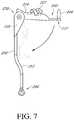
- FIG. 7illustrates a crutch 200 which is substantially similar to embodiment 100 except as shown and/or described herein, or as would be inherent. Further, those skilled in the art will appreciate that the embodiment 100 (and thus crutch 200) may be modified in various ways, such as through incorporating all or part of any of the various described embodiments, for example. For uniformity and brevity, reference numbers between 200 and 299 may be used to indicate parts corresponding to those discussed above numbered between 100 and 199, though with any noted or described deviations.
- the arm rest 224may be pivotally connected to the main body 205 and/or the leg 250 via a hinged connection 270.
- the arm rest 224may thus be rotatable from about 0 to 135 degrees relative to horizontal, as illustrated.
- the main body 205may be modified such that an opening is formed therein to receive the arm rest 224.
- the leg 250may include an angled portion 253, as shown, to provide shock absorbing benefits to the crutch 200. Accordingly, the leg 250 may be formed from any material sufficient to allow the leg 250 to slightly flex and subsequently return to its original position.
- the crutch 200may be configured such that a button, for example, on the handle 240, allows the user to easily change the position of the arm rest 224. This may be particularly useful when the user is, for example, ascending or descending stairs.
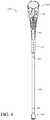
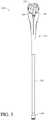
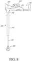
- FIG. 8illustrates a crutch 300 which is substantially similar to embodiment 100 except as shown and/or described herein, or as would be inherent. Further, those skilled in the art will appreciate that the embodiment 100 (and thus crutch 300) may be modified in various ways, such as through incorporating all or part of any of the various described embodiments, for example. For uniformity and brevity, reference numbers between 300 and 399 may be used to indicate parts corresponding to those discussed above numbered between 100 and 199, though with any noted or described deviations.
- the leg 350may be a single straight leg tube.
- the main body 305may include a single substantially vertical tubular member 310 for interacting with the leg 350, and an arm rest support 318.
- the arm rest support 318may be fixed to the substantially vertical tubular member 310 at an angle of between approximately 0 to 15 degrees relative to horizontal.
- a cradle 325may be received into the arm rest support 325, and a handle 240 may extend from the arm rest support 318 as described above.
- FIGs. 10 and 11illustrate a walker 400, comprising two or more crutches as described herein to form a walker.
- the walker 400is described with reference to the use of crutches according to the embodiment 100. However, it shall be understood that any of the crutches 100, 200, 300 described herein may alternately, or additional be incorporated into walker 400 as appropriate.
- walker 400two crutches 100 may be fastened together to form a walker 400.
- the crutches 100may be attached together via a bracket 480 ( FIG. 10 ).
- the bracket 480may be secured to each of the respective crutches 100 with a mechanical fastener, such as a screw.
- each individual crutch 100may be equipped with means for receiving an end of a structural rod member 485.
- the crutches 100may be placed in parallel positions, and the structural rod member 485 may be received by the crutches 100 and secured in position to form the walker 400.
- the feet 470 of the crutches 100may be elongated.
- the walker 400may include four crutches 100, secured together via brackets 480 and/or structural rod members 485 in an open square configuration.
- Small casters 471may additionally be placed in the corners (e.g., at the ends of the elongated feet, at each foot, etc.) for increased maneuverability.
- a pedometermay be housed inside the device (for example, in the main body 105) to track activity levels.
- the pedometermay be in wireless communication with, for example, a smart phone or other tracking device.
- Other electronic modules or multipurpose modulusmay be included to measure and provide information on other physiological parameters, such as blood-pressure and heart-rate monitors, as well as means for tracking number of calories burned.
- Still additional metrics that may be trackedinclude speed, points of stress, number of minutes the crutch is used per day, et cetera. The data may be relevant for developing tools for managing the user's health and for maximizing the life of the crutch.
- each crutch 100may be equipped with a means for snapping, locking, or otherwise attaching pairs of crutches 100 together for ease of carrying the crutches 100.
- magnetsmay be provided in the main body 105 of each crutch 100 such that, when positioned together, the crutches 100 stick together.
- a first crutch 100may be equipped with a hook, and a second crutch 100 equipped with means for engaging with the hooks, such that the crutches 100 may be attached for easy transportation.
- Other attachment meansmay additionally, or alternately, be appropriate for connecting individual crutches together.
Landscapes
- Health & Medical Sciences (AREA)
- Epidemiology (AREA)
- Pain & Pain Management (AREA)
- Physical Education & Sports Medicine (AREA)
- Rehabilitation Therapy (AREA)
- Life Sciences & Earth Sciences (AREA)
- Animal Behavior & Ethology (AREA)
- General Health & Medical Sciences (AREA)
- Public Health (AREA)
- Veterinary Medicine (AREA)
- Rehabilitation Tools (AREA)
Description
- The crutch is a mobility aid that is widely used throughout the world. Crutches allow the user to support their body weight in the event that the lower extremities of the body are unable to do so. Typically, a crutch is provided for each side of the body, and often are configured to fit beneath the under arms of the user. Handles are located on the crutches, and the user such that, in use, the person's weight is distributed between the under arms, the hands, and the wrists of the user.
- There are several disadvantages to traditional crutches. Many people have difficulty coordinating movement with crutches due to the uncomfortable positioning of the crutches at the underarms. Further, the user may quickly become fatigued, and the stress placed on the user's hands and wrists may perpetuate further injury. It would be desirable to have a crutch that allows for an easier transition for the user and that allows the user to make use of his or her elbows and/or upper arms to support the body weight.
- Different crutches or walking aids have been presented before in literature. A crutch, which includes a vertical support member and a forearm support is described in
US 5671765 A . - The crutch according to the invention is defined in claim 1. Preferred embodiments are defined in the dependent claims.
FIG. 1 is a perspective view of a crutch according to one embodiment of the invention.FIG. 2 is an exploded perspective view of the crutch according to the embodiment ofFIG. 1 .FIG. 3 is a side view of the crutch according to the embodiment ofFIG. 1 .FIG. 3A is a side view of the crutch showing the arm rest cradle in an open position.FIG. 3B is a top perspective view of the crutch ofFIG. 3A .FIG. 4 is a rear view of the crutch according to the embodiment ofFIG. 1 .FIG. 5 is a front view of the crutch according to the embodiment ofFIG. 1 .FIG. 6 is a top view of the crutch according to the embodiment ofFIG. 1 .FIG. 7 is a side view of a crutch.FIG. 8 is a side view of a crutch.FIG. 9 is a close up perspective view of a foot.FIG. 10 is a perspective view of two crutches secured together to form a walkerFIG. 11 is a front view of the embodiment ofFIG. 10 .- Embodiments of crutches are disclosed herein. In one embodiment, illustrated by
FIGs. 1-6 , acrutch 100 has amain body structure 105 and aleg 150 attached to aninterchangeable foot 160 for contacting the ground. Themain body 105 may include a substantially verticaltubular member 110 leading to a firstangled portion 113 which extends upwardly at an angle to a second oppositelyangled portion 115 leading to anarm rest support 118 having ahandle 140 extending therefrom. - Referring to
FIGs. 1 and4 , the main body verticaltubular member 110 may be hollow in order to receive theleg 150. As is described in greater detail below, theleg 150 may be equipped with a mechanical fastening mechanism, such as a quick release button, which may engage withapertures 112 formed in a backside of the verticaltubular member 110. - The vertical
tubular member 110 extends upwardly toward the firstangled portion 113, which extends upwardly in a forward direction at a predetermined angle between 0 and 90 degrees relative to horizontal. The firstangled portion 113 may also be hollowed, forming avoid 116 therein. Thevoid 116 may be used, for example, as a pocket for storing a user's valuables, such as a keys or a cell phone, or may be equipped to hold other personal items such as a water bottle. To prevent the contents of thepocket 116 from slipping, and to minimize movement within thepocket 116, thepocket 116 may be equipped with a rubber (or other similar material) coating. Additionally,handles 117 may be formed into the sides of theangled portion 113 for ease of carrying thecrutch 113. - The first
angled portion 113 is so designed in order to provide thecrutch 100 with shock absorbing capabilities. As the user relies on thecrutch 100 and a portion of the user's body weight is transferred to thecrutch 100, and theangled portion 113 is allowed to flex slights such that theangled portion 113 absorbs a portion of the force, transferring the transferred force away from the user's arms, hands, and/or under arms.Ribs 116, illustrated inFIG. 4 , may be formed or placed around the interior surface of theangled portion 113 to provide reinforcement to theangled portion 113 and strength to themain body 105. Although not shown in the drawings, covers may be provided to snap (or otherwise attach) to themain body 105 to cover theribs 116. - Moving on, and as described above, the first
angled portion 113 extends upwardly to the secondangled portion 115, which extends outwardly therefrom to form thearm rest support 118. As illustrated inFIGs. 2-3 , thearm rest support 118 may be configured to engage with anarm rest 124. Thearm rest 124 may include acradle 125 configured to receive the user's forearm. Accordingly, thecradle 125 may include a first end comprising anelbow cup 127 for receiving the user's elbow, and a secondopen end 128 opposite theelbow cup 127, allowing the user's arm to extend outwardly therefrom. As described in greater detail below,bracing 129 may be provided and secured at positions along the outer edges of thecradle 125. - Referring now to
FIGs. 3 ,3A, and 3B , in one embodiment, thecradle 125 may be hingedly connected to thearm rest support 118 via hingedconnection 122. Thecradle 125 may pivot about thehinged connection 122 as shown inFIGs. 3A and 3B .Teeth 130 may be provided along an underside of thecradle 125, which may engage withapertures arm rest support 118. Thecradle 125 may be secured to thearm rest support 118 via asliding lock 123, for example, to prevent thecradle 125 from unexpectedly or undesirably detaching from thearm rest support 118. - In one embodiment, the
arm rest support 118 may be held at a fixed position approximately 0 to 15 degrees relative to horizontal. Accordingly, thearm rest 124 may also be held at a position approximately 0 to 15 degrees relative to horizontal. - Padding 226, such as a foam insert, may be provided in the
cradle 125 to provide maximum comfort and impact absorption. Foams of varying densities may be used depending on the user's specific requirements and comfort. Moreover, multiple layers of foam and/or other padding may be used to pad thecradle 125. It may be desirable for thepadding 126 to be hydrophobic and/or antimicrobial to resist sweat and microbial growth. Fabric may additionally be provided for comfort. Theelbow cup 127 may further include a gel pocket, either separately or embedded in the foam liner in order to provide extra padding, as theelbow cup 127 may receive the majority of the user's weight. In one embodiment, thepadding 126 may be constructed of a first layer of single density foam, a gel pocket encapsulated at the area of theelbow cup 127, and a second layer of antimicrobial fabric. - The
padding 127 may be removable such that the user can switch out the liners. Accordingly, thepadding 127 may be secured to thecradle 125 via an adhesive (e.g., double sided tape, Velcro, etc.) or a mechanical attachment (e.g., snaps, hooks, etc.). Those of skill in the art will recognize that it may be beneficial for thepadding 126 to have perforations to promote airflow. - Optionally, an upper arm sleeve may be attached to the back of the
elbow cradle 127. The upper arm sleeve may provide stability to thecrutch 100 when in use. The upper arm sleeve may be allowed to flex in order to support the user's upper arm to still permit natural movement of the user's arm. In one embodiment, the upper arm sleeve may include first and second arms, positioned on either side of the elbow cradle 30, and attached thereto with a spring loaded hinge or other appropriate mechanical fastening mechanism. A band may be secured to the free ends of the arms, and may be configured to wrap partially or completely around the user's upper arm. The spring loaded hinge may bias the upper arm sleeve in the direction of the user's arms. In use, the user's arms may overcome the force of the spring to bias the upper arm sleeve in the opposite direction. Accordingly, the upper arm sleeve may be configured to maintain constant contact with the user's upper arms. - The
arm rest 124 may further be equipped with bracing 129 to maintain the user's arms in thecradle 125. The bracing 129 may include straps secured at one end to respective positions along either side of thecradle 125, the other end extending at least partially over thecradle 125. To allow for personalized positioning of the bracing 129, apertures (such as those shown inFIG. 8 at 331) may be formed along either or both sides of the length of thecradle 125 to serve as the connection point for the bracing 139. Various fastening mechanisms may be employed on one end of the straps to secure the bracing 129 to thecradle 125, such as snaps, rivets, screws, etc. Alternately, a t-bar slot may be formed along the outer edge of thecradle 125, and the straps may be equipped with a respective t-bar to engage with the t-bar slot. Those of ordinary skill in the art may recognize that the t-bar slot/t-bar fastening mechanism may allow the user the most flexibility in choosing the best position for the bracing 129. - The bracing 129 may be configured to restrain the user's arm while in normal use with the
crutch 100, but to allow for a quick release of the user's arm when necessary. Accordingly, the bracing 129 may be constructed of a flexible plastic, or other flexible material. One exemplary material is ethylene vinyl acetate (EVA), which can be easily molded according to the size and shape of the user's arm. To mold EVA bracing 129, the user may place the individual straps into boiling water to make the EVA malleable. Then, the straps may be bent to the desired shape. - In another embodiment, the device may additionally, or alternately, utilize Velcro or other similar straps to secure the user's arms in the
cradle 125. Other exemplary bracing mechanisms may include the use of rigid (e.g., hard plastic) straps in a hinged connection with thecradle 125, such as those shown inFIG. 3A and 3B . Respective rigid straps may be located opposite each other on either side of thecradle 125, or on a single side of thecradle 125, and extend partially over thecradle 125. A gap may be provided between rigid straps extending from either side of thecradle 125 to allow the user to break free of the straps. - Those of skill in the art may recognize that the apertures (e.g., 331) formed in the
cradle 125 may provide additional or alternative benefits to the user. For example, specially designed hooks, clips, trays, containers, or other accessories may be attached to thecrutch 100, allowing the user to carry objects that he or she would otherwise not be able to carry, such as a purse or bag, grocery basket, food tray, pot of water, laundry basket, beverage, phone, etc. - Moving on, as briefly described above, the
handle 140 extends outwardly from thearm rest support 118. Thehandle 140 may include an extension member 142 agripping portion 144. Theextension member 142 may be, for example, a telescoping rod having a proximal end 142B configured to engage with achannel 121 formed in the underside of thearm rest support 116, and adistal end 142A. To provide the most comfortable and natural fit, it may be beneficial for thechannel 121 to be offset from the center of thearm rest support 118 by approximately 0 to 25 degrees. To customize the length of theextension member 142, theextension member 142 may be equipped with one or more quick release buttons (or other appropriate locking device) for engaging with respective openings 120 (FIGs. 2 and3B ) which may be formed along a length of thearm rest support 118 corresponding to thechannel 121. To position theextension member 142, the user (or a person aiding the user) may disengage the locking device from theopening 120 in thechannel 121. Theextension member 142 may then be moved in the desired direction until the locking device on theextension member 142 engages with the desiredopening 121. This process may be repeated until thehandle 140 is at the desired distance. - Alternatively, the gripping
portion 144 may be equipped with a length adjustment mechanism (e.g.,button 144A) that releases theextension member 142 from its engagement with thechannel 121 in order to move theextension member 142 to the desired position. In one embodiment, the button may be connected to a cable mechanism that may engage an element connected to a locking pin to move thehandle 140 to the correct position for the user. - The gripping
portion 144 may be secured to, and extend perpendicularly from, the extension memberdistal end 142A at an angle between approximately 0 and 15 degrees relative to vertical. In one embodiment, the grippingportion 144 may be secured to theextension member 142 via a bracket 136. In another embodiment, the grippingportion 144 may be secured via one ormore hinges 137 or ball joint (e.g.,FIG. 3A ) for maximum rotation. The handle 35 may be configured to tilt along the x-z plane (e.g., toward and away from the user) and rotate about the y-z plane (e.g, left and right of the user). A button (e.g.,button 144A) may be provided on thehandle gripping portion 144 to release the hold of thegripping portion 144 on theextension member 142. Thus, to rotate thegripping portion 144 about theextension member 142, for example, the user may press thebutton 144A and move thegripping portion 144 to the desired position. - Additional embodiments of the
handle 140 may alternately be realized to provide additional or alternative benefits to the user. Various mechanisms may lock thehandle 140 in the desired position. In one embodiment, thegrip 144 may andextension member 142 may be equipped with respective threading. To move thegrip 144, thegrip 144 may be "unscrewed" and rotated into the desired position, and then rotated in the opposite direction to lock thegrip 144 in place. - Referring now to
FIG. 4 , theleg 150 telescopically engages with the substantially verticaltubular member 110 of themain body 105. Accordingly, theleg 150 may be equipped with one or more quick release connectors 152 (or other appropriate fastening mechanism) which may interact withcorresponding apertures 112 formed in the substantially verticaltubular member 110. Thequick release connectors 152 may be provided at various positions along the leg 150 (e.g., at the top of theleg 150, near the middle of theleg 150, etc., as shown inFIG. 4 ) to allow for maximum height adjustment. - To change the position of the
leg 150, thequick release connector 152 may be pressed in by the user (or the person aiding the user) and theleg 150 moved in and out of thetubular member 110 until the desired height is reached. For transporting purposes, it may be desirable for theleg 150 to be inserted as far as possible into thetubular member 110 to minimize the footprint of thecrutch 100. - As shown in the figures, the
foot 160 may extend from theleg 150 and may be configured to provide a means for efficiently and comfortably contacting the ground. Typically, a person's foot moves in a heel-to-toe manner when walking. However, prior art crutches often come with a rubber end that is perfectly flat. While the rubber allows for some flexibility to move with the person, the natural tendency of the foot is to be completely flat on the ground. - In one embodiment, illustrated in
FIG. 9 , thefoot 160 may include aneck 162 having at least one mechanical fastener (such as a quick release connector 166) formed thereon, and a hollowedannular member 164 extending downwardly from theneck 162. Theneck 162 of thefoot 160 may be received into the end of theleg 150 such that themechanical fastener 166 engages with anaperture 154 formed in theleg 150 to secure thefoot 160 thereto. Therefore, it shall be understood that the foot 50 may be interchangeable. - The
foot 160 may be formed of flexible plastic, such as acrylonitrile butadiene styrene (ABS), which may allow for slight compression of theannular member 164 of thefoot 160 as forced is placed on thecrutch 100, thereby providing additional shock-absorption benefits. Different strength materials may alternatively be utilized in order to accommodate a range of weights. Due to the annular nature of thefoot 160, thecrutch 100 may move in a more natural way across the ground, as thefoot 160 may be able to emulate the movement of a human's foot as it travels across the ground. - The hollowed
annular member 164 may be covered with treading 168 for gripping. Since thefoot 160 may be interchangeable due to the ability to remove thefoot 160 from the end of theleg 150, various feet may be provided, each being configured for a specific situation. For example, there are different tread styles that are beneficial depending on the weather. Therefore, one interchangeable foot 50 may be equipped with a tread design suitable for everyday use. Other interchangeable feet 50 may be for indoor use, use in the rain, ice and/or snow. Additionally, other types or shapes of feet may also be desirable. For example, there may be situations in which an off-the-shelf crutch foot may be desirable. Furthermore, carbon-fiber feet may be desirable where the user wishes to use thecrutches 100 in an athletic manner. Still further types of feet that may be incorporated onto thecrutch 100 include a tripod or a quad foot which may increase the stability of thecrutch 100. - In another embodiment, to provide further traction, an opening may be formed in the bottom rim of the hollowed
annular member 164, and the top rim of the hollowedannular member 164 may be equipped with a pin. As the user walks, the force of the user's weight oncrutch 100 may cause thefoot 160 to compress slightly, causing the pin to protrude through the opening, and into the ground. It may be understood that afoot 160 having a pin would not be desirable on hard surfaces, such as concrete or asphalt. - In one embodiment, the
foot 160 may be equipped with a cover that slides into place over thefoot 160 upon activation of a trigger. The trigger may be located, for example, on thehandle 140 of thecrutch 100, and the user may activate the trigger, causing the cover to move into place over thefoot 160. The trigger may then be pushed again to move the cover off thefoot 160, or to separate the cover from thefoot 160 entirely. FIG. 7 illustrates a crutch 200 which is substantially similar toembodiment 100 except as shown and/or described herein, or as would be inherent. Further, those skilled in the art will appreciate that the embodiment 100 (and thus crutch 200) may be modified in various ways, such as through incorporating all or part of any of the various described embodiments, for example. For uniformity and brevity, reference numbers between 200 and 299 may be used to indicate parts corresponding to those discussed above numbered between 100 and 199, though with any noted or described deviations.- In crutch 200, the
arm rest 224 may be pivotally connected to themain body 205 and/or theleg 250 via a hingedconnection 270. Thearm rest 224 may thus be rotatable from about 0 to 135 degrees relative to horizontal, as illustrated. To accommodate the degrees of rotation of thearm rest 224, themain body 205 may be modified such that an opening is formed therein to receive thearm rest 224. Further, theleg 250, may include anangled portion 253, as shown, to provide shock absorbing benefits to the crutch 200. Accordingly, theleg 250 may be formed from any material sufficient to allow theleg 250 to slightly flex and subsequently return to its original position. - The crutch 200 may be configured such that a button, for example, on the handle 240, allows the user to easily change the position of the
arm rest 224. This may be particularly useful when the user is, for example, ascending or descending stairs. FIG. 8 illustrates a crutch 300 which is substantially similar toembodiment 100 except as shown and/or described herein, or as would be inherent. Further, those skilled in the art will appreciate that the embodiment 100 (and thus crutch 300) may be modified in various ways, such as through incorporating all or part of any of the various described embodiments, for example. For uniformity and brevity, reference numbers between 300 and 399 may be used to indicate parts corresponding to those discussed above numbered between 100 and 199, though with any noted or described deviations.- In crutch 300, the
leg 350 may be a single straight leg tube. Themain body 305 may include a single substantially verticaltubular member 310 for interacting with theleg 350, and anarm rest support 318. Thearm rest support 318 may be fixed to the substantially verticaltubular member 310 at an angle of between approximately 0 to 15 degrees relative to horizontal. Acradle 325 may be received into thearm rest support 325, and a handle 240 may extend from thearm rest support 318 as described above. FIGs. 10 and11 illustrate awalker 400, comprising two or more crutches as described herein to form a walker. For ease of reference, thewalker 400 is described with reference to the use of crutches according to theembodiment 100. However, it shall be understood that any of thecrutches 100, 200, 300 described herein may alternately, or additional be incorporated intowalker 400 as appropriate.- In
walker 400, twocrutches 100 may be fastened together to form awalker 400. Here, thecrutches 100 may be attached together via a bracket 480 (FIG. 10 ). Thebracket 480 may be secured to each of therespective crutches 100 with a mechanical fastener, such as a screw. Alternately, eachindividual crutch 100 may be equipped with means for receiving an end of astructural rod member 485. Thecrutches 100 may be placed in parallel positions, and thestructural rod member 485 may be received by thecrutches 100 and secured in position to form thewalker 400. To provide stability, thefeet 470 of thecrutches 100 may be elongated. In another embodiment of thewalker 400, not shown, thewalker 400 may include fourcrutches 100, secured together viabrackets 480 and/orstructural rod members 485 in an open square configuration.Small casters 471 may additionally be placed in the corners (e.g., at the ends of the elongated feet, at each foot, etc.) for increased maneuverability. - Various additional devices may also be incorporated into each
crutch - Further, each
crutch 100 may be equipped with a means for snapping, locking, or otherwise attaching pairs ofcrutches 100 together for ease of carrying thecrutches 100. In one embodiment, magnets may be provided in themain body 105 of eachcrutch 100 such that, when positioned together, thecrutches 100 stick together. In another embodiment, afirst crutch 100 may be equipped with a hook, and asecond crutch 100 equipped with means for engaging with the hooks, such that thecrutches 100 may be attached for easy transportation. Other attachment means may additionally, or alternately, be appropriate for connecting individual crutches together. - Many different arrangements of the described invention are possible without departing from the scope of the present invention as defined by the appended claims. Embodiments of the present invention are described herein with the intent to be illustrative rather than restrictive.
Claims (12)
- A crutch, comprising:a tubular member being substantially vertical and having a plurality of apertures formed therein;an angled portion extending upwardly from the substantially vertical tubular member;an arm rest support extending perpendicularly from the angled portion for receiving an arm rest;a handle extending outwardly from the arm rest support;a leg telescopically received into the tubular member; anda foot; andwherein the foot is exchangably received by the leg;
characterized by the arm rest being hingedly connected to the arm rest support. - The crutch of claim 1, wherein the arm rest comprises a cradle having a first end comprising an elbow cup and an opposing open second end.
- The crutch of claim 2, wherein the cradle is covered with padding.
- The crutch of claim 2, wherein the arm rest further comprises a brace, the brace being secured to an outside edge of the cradle and extending partially over the cradle.
- The crutch of claim 2, wherein the teeth on a bottom side of the arm rest engage with corresponding apertures formed in the arm rest support.
- The crutch of claim 1, wherein the arm rest support is fixed at an angle approximately 0 to 15 degrees relative to horizontal.
- The crutch of claim 1, wherein the handle comprises an extension member having a distal end and a proximal end, and a gripping portion secured to the extension member distal end, the gripping portion being rotatable about the extension member distal end; and wherein the extension member proximal end is received into a channel formed in a bottom side of the arm rest support;
- The crutch of claim 7, wherein the extension member proximal end includes a mechanical fastener, the mechanical fastener respectively engaging with one of a plurality of openings formed in the arm rest support channel.
- The crutch of claim 1, wherein the foot comprises a neck received by the leg, and an annular member having a hollow center and an outer surface at least partially covered by treading.
- The crutch of claim 1, wherein the handle is offset from a center of the arm rest by approximately 0 to 25 degrees.
- The crutch of claim 1, wherein the foot comprises a releasable locking mechanism which engages with an aperture formed in a lower portion of the leg.
- The crutch of claim 1, wherein the tubular member, the angled portion and the arm rest support are formed of a single piece of material.
Applications Claiming Priority (3)
| Application Number | Priority Date | Filing Date | Title |
|---|---|---|---|
| US201562142235P | 2015-04-02 | 2015-04-02 | |
| US201562253789P | 2015-11-11 | 2015-11-11 | |
| PCT/US2016/025684WO2016161353A1 (en) | 2015-04-02 | 2016-04-01 | Crutch |
Publications (3)
| Publication Number | Publication Date |
|---|---|
| EP3277243A1 EP3277243A1 (en) | 2018-02-07 |
| EP3277243A4 EP3277243A4 (en) | 2018-11-07 |
| EP3277243B1true EP3277243B1 (en) | 2020-05-27 |
Family
ID=57006389
Family Applications (1)
| Application Number | Title | Priority Date | Filing Date |
|---|---|---|---|
| EP16774360.8AActiveEP3277243B1 (en) | 2015-04-02 | 2016-04-01 | Crutch |
Country Status (5)
| Country | Link |
|---|---|
| US (1) | US10231896B2 (en) |
| EP (1) | EP3277243B1 (en) |
| AU (1) | AU2016244011B2 (en) |
| TW (1) | TWI686189B (en) |
| WO (1) | WO2016161353A1 (en) |
Families Citing this family (15)
| Publication number | Priority date | Publication date | Assignee | Title |
|---|---|---|---|---|
| US10532001B2 (en)* | 2015-04-02 | 2020-01-14 | Mobility Designed, Inc. | Crutch |
| US10898405B2 (en) | 2015-04-02 | 2021-01-26 | Mobility Designed, Inc. | Crutch |
| US9987189B2 (en)* | 2015-11-09 | 2018-06-05 | Steven Dropsho | Mobility assistance device |
| US9974368B1 (en)* | 2016-02-11 | 2018-05-22 | John Moore | Cane |
| USD804675S1 (en)* | 2016-07-08 | 2017-12-05 | Mobility Designed, Llc | Attachment portion for a crutch |
| WO2018017666A1 (en) | 2016-07-19 | 2018-01-25 | Orndorff Joshua | Multiple terrain mobility device |
| US10064781B2 (en)* | 2016-12-01 | 2018-09-04 | Össur Iceland Ehf | Crutch with energy storage and energy return |
| CN107242654A (en)* | 2017-06-23 | 2017-10-13 | 厦门源创意智能科技有限公司 | Multiway cane formula walk helper |
| JP6836691B2 (en)* | 2017-09-12 | 2021-03-03 | モビリティ デザインド インコーポレイテッドMobility Designed,Inc. | Cane |
| KR20200017187A (en)* | 2018-08-08 | 2020-02-18 | 현대자동차주식회사 | Crutch of joint structure |
| US11510842B2 (en)* | 2019-07-17 | 2022-11-29 | Delphine HC Innovations, LLC | Ergonomic ambulation assist device |
| CN115835847A (en)* | 2020-07-15 | 2023-03-21 | 美商行动设计股份有限公司 | Reclining crutch |
| CN112155953A (en)* | 2020-10-27 | 2021-01-01 | 厦门铠胜医疗器械有限公司 | Portable walking stick and using method thereof |
| US12376657B2 (en)* | 2021-02-09 | 2025-08-05 | Therex, Llc | Mobility assist device including exercising components, and systems and methods thereof |
| US20240277553A1 (en)* | 2023-02-17 | 2024-08-22 | 9303-2183 Quebec Inc. | Ambulatory support device |
Family Cites Families (27)
| Publication number | Priority date | Publication date | Assignee | Title |
|---|---|---|---|---|
| US3947140A (en) | 1974-07-03 | 1976-03-30 | Temco Products, Inc. | Connector for telescoping tubular stick members |
| USD258096S (en)* | 1978-06-13 | 1981-02-03 | Bent Barfod | Adjustable crutch |
| US4708154A (en)* | 1985-12-05 | 1987-11-24 | Edwards Robert J | Nonslip crutch foot assembly |
| JPH03292956A (en)* | 1990-04-09 | 1991-12-24 | Toshiaki Miyoshi | Stick for handicapped person |
| US5329954A (en) | 1992-12-23 | 1994-07-19 | Ohta Inc. | Stick-like means for physically handicapped person |
| US5301704A (en)* | 1993-03-18 | 1994-04-12 | Brown E Evangeline | Walking cane usable on slippery and icy surfaces |
| US5671765A (en)* | 1995-02-21 | 1997-09-30 | Hagberg, Jr.; Nils G. | Forearm crutch |
| US5564451A (en) | 1995-02-21 | 1996-10-15 | Hagberg; Nils G. | Forearm crutch |
| US5499645A (en)* | 1995-07-11 | 1996-03-19 | Baliga; Arvind B. | Dual stair step walker with assist bar |
| US20040020525A1 (en) | 2002-08-02 | 2004-02-05 | Harry Lev | Combination crutch-walker |
| US7621288B2 (en)* | 2002-09-23 | 2009-11-24 | Evans Jeffrey D | Hand based weight distribution system |
| US7494138B2 (en)* | 2006-09-25 | 2009-02-24 | Gary Graham | Bipedal motion assisting method and apparatus |
| AU2009279416A1 (en)* | 2008-08-06 | 2010-02-11 | Colin Patrick Albertyn | A crutch |
| US20140052039A1 (en)* | 2012-08-20 | 2014-02-20 | 3D Systems, Inc. | Spiral brace |
| US9032982B2 (en)* | 2012-03-23 | 2015-05-19 | 3D Systems, Inc. | Crutch apparatus and method for designing and fabricating |
| DE102009037960A1 (en)* | 2009-04-01 | 2010-10-07 | Kaupe, Georg H., Dr. | Exercise pole for e.g. Nordic walker, has lower arm support hingably attached at upper end of elongate pole, where support is pivotable to larger inclination angle against force of spring or elastic resetting element |
| WO2011060178A1 (en) | 2009-11-11 | 2011-05-19 | Mobi Llc | Ergonomic crutch |
| TWM411823U (en)* | 2011-04-29 | 2011-09-21 | Smart Plan Internat Co Ltd | Structure of handle for cane |
| TWM426345U (en)* | 2011-09-30 | 2012-04-11 | Jan Mao Ind Co Ltd | Arm-disc handle for children walking aided apparatus |
| ES2431414B1 (en)* | 2012-05-22 | 2014-07-28 | Ignacio MAÑERO LOJENDIO | Crutch with inclined forearm support and cushioning |
| US10137050B2 (en)* | 2013-01-17 | 2018-11-27 | Rewalk Robotics Ltd. | Gait device with a crutch |
| US20140265256A1 (en)* | 2013-03-12 | 2014-09-18 | Polly Rothstein | Systems and methods for moving people |
| US9016297B2 (en)* | 2013-03-15 | 2015-04-28 | Gregg Salomon | Wheeled support cane |
| EP3013301A4 (en)* | 2013-06-27 | 2017-01-11 | Better Walk, Inc. | Mobility aids and related methods |
| US9289347B2 (en)* | 2014-02-06 | 2016-03-22 | Richard Randal Powell | Erect posture mobility device with low turn radius |
| US9585807B2 (en)* | 2015-05-16 | 2017-03-07 | Protostar, Inc., a Delaware Corporation | Collapsible upright wheeled walker apparatus |
| ES1216611Y (en) | 2018-07-02 | 2018-11-07 | Improving Mobility Dev Sl | Sturdy cane with ergonomic angulation |
- 2016
- 2016-04-01WOPCT/US2016/025684patent/WO2016161353A1/ennot_activeCeased
- 2016-04-01TWTW105110630Apatent/TWI686189B/enactive
- 2016-04-01EPEP16774360.8Apatent/EP3277243B1/enactiveActive
- 2016-04-01AUAU2016244011Apatent/AU2016244011B2/ennot_activeCeased
- 2016-04-01USUS15/089,048patent/US10231896B2/enactiveActive
Non-Patent Citations (1)
| Title |
|---|
| None* |
Also Published As
| Publication number | Publication date |
|---|---|
| AU2016244011A1 (en) | 2017-10-26 |
| US10231896B2 (en) | 2019-03-19 |
| TW201703748A (en) | 2017-02-01 |
| WO2016161353A1 (en) | 2016-10-06 |
| EP3277243A4 (en) | 2018-11-07 |
| TWI686189B (en) | 2020-03-01 |
| US20160287464A1 (en) | 2016-10-06 |
| EP3277243A1 (en) | 2018-02-07 |
| AU2016244011B2 (en) | 2020-02-20 |
Similar Documents
| Publication | Publication Date | Title |
|---|---|---|
| EP3277243B1 (en) | Crutch | |
| US10532001B2 (en) | Crutch | |
| US11872182B2 (en) | Crutch | |
| EP3681458B1 (en) | Crutch | |
| US8061376B2 (en) | Stable wheeled walker device | |
| TWI279241B (en) | Carrying device, shoulder strap assembly, methods for carrying and engaging | |
| HK1204464A1 (en) | Limb support and ground sliding exercise system | |
| US6164305A (en) | Mobility assisting device | |
| KR101433339B1 (en) | Stick | |
| WO2009026312A2 (en) | Walker with underarm supports | |
| WO2011008338A1 (en) | Child carrier | |
| US5378217A (en) | Hand held exercise device providing desirable air resistance | |
| EP2371338B1 (en) | A walking aid | |
| US5752535A (en) | Crutch | |
| US20100154850A1 (en) | Covertible trek pole | |
| WO2005072348A2 (en) | Flexible rod support member for packs, bags and other articles | |
| US20170296907A1 (en) | Anti-fatigue grip for poles | |
| US20060278176A1 (en) | Baby walking assisting device | |
| US20040262357A1 (en) | Flexible rod support member for packs, bags and other articles | |
| JP2006075557A (en) | Handsfree umbrella holder | |
| JP3077297U (en) | Umbrella attachable cane | |
| CN120267924A (en) | Multifunctional knapsack type infusion auxiliary device | |
| CN112004512A (en) | Walking stick accessory group | |
| HK1162912B (en) | A walking aid | |
| KR20090123216A (en) | Multifunctional hat with ring gel hanger |
Legal Events
| Date | Code | Title | Description |
|---|---|---|---|
| STAA | Information on the status of an ep patent application or granted ep patent | Free format text:STATUS: THE INTERNATIONAL PUBLICATION HAS BEEN MADE | |
| PUAI | Public reference made under article 153(3) epc to a published international application that has entered the european phase | Free format text:ORIGINAL CODE: 0009012 | |
| STAA | Information on the status of an ep patent application or granted ep patent | Free format text:STATUS: REQUEST FOR EXAMINATION WAS MADE | |
| 17P | Request for examination filed | Effective date:20171030 | |
| AK | Designated contracting states | Kind code of ref document:A1 Designated state(s):AL AT BE BG CH CY CZ DE DK EE ES FI FR GB GR HR HU IE IS IT LI LT LU LV MC MK MT NL NO PL PT RO RS SE SI SK SM TR | |
| AX | Request for extension of the european patent | Extension state:BA ME | |
| DAV | Request for validation of the european patent (deleted) | ||
| DAX | Request for extension of the european patent (deleted) | ||
| A4 | Supplementary search report drawn up and despatched | Effective date:20181010 | |
| RIC1 | Information provided on ipc code assigned before grant | Ipc:A61H 3/02 20060101AFI20181004BHEP Ipc:A45B 1/00 20060101ALI20181004BHEP Ipc:A45B 3/12 20060101ALI20181004BHEP Ipc:A45B 3/00 20060101ALI20181004BHEP Ipc:A61H 3/00 20060101ALI20181004BHEP | |
| RAP1 | Party data changed (applicant data changed or rights of an application transferred) | Owner name:MOBILITY DESIGNED, INC. | |
| GRAP | Despatch of communication of intention to grant a patent | Free format text:ORIGINAL CODE: EPIDOSNIGR1 | |
| STAA | Information on the status of an ep patent application or granted ep patent | Free format text:STATUS: GRANT OF PATENT IS INTENDED | |
| INTG | Intention to grant announced | Effective date:20191213 | |
| GRAS | Grant fee paid | Free format text:ORIGINAL CODE: EPIDOSNIGR3 | |
| GRAA | (expected) grant | Free format text:ORIGINAL CODE: 0009210 | |
| STAA | Information on the status of an ep patent application or granted ep patent | Free format text:STATUS: THE PATENT HAS BEEN GRANTED | |
| AK | Designated contracting states | Kind code of ref document:B1 Designated state(s):AL AT BE BG CH CY CZ DE DK EE ES FI FR GB GR HR HU IE IS IT LI LT LU LV MC MK MT NL NO PL PT RO RS SE SI SK SM TR | |
| REG | Reference to a national code | Ref country code:GB Ref legal event code:FG4D | |
| REG | Reference to a national code | Ref country code:CH Ref legal event code:EP | |
| REG | Reference to a national code | Ref country code:DE Ref legal event code:R096 Ref document number:602016037111 Country of ref document:DE | |
| REG | Reference to a national code | Ref country code:AT Ref legal event code:REF Ref document number:1273782 Country of ref document:AT Kind code of ref document:T Effective date:20200615 | |
| REG | Reference to a national code | Ref country code:LT Ref legal event code:MG4D | |
| PG25 | Lapsed in a contracting state [announced via postgrant information from national office to epo] | Ref country code:LT Free format text:LAPSE BECAUSE OF FAILURE TO SUBMIT A TRANSLATION OF THE DESCRIPTION OR TO PAY THE FEE WITHIN THE PRESCRIBED TIME-LIMIT Effective date:20200527 Ref country code:FI Free format text:LAPSE BECAUSE OF FAILURE TO SUBMIT A TRANSLATION OF THE DESCRIPTION OR TO PAY THE FEE WITHIN THE PRESCRIBED TIME-LIMIT Effective date:20200527 Ref country code:GR Free format text:LAPSE BECAUSE OF FAILURE TO SUBMIT A TRANSLATION OF THE DESCRIPTION OR TO PAY THE FEE WITHIN THE PRESCRIBED TIME-LIMIT Effective date:20200828 Ref country code:SE Free format text:LAPSE BECAUSE OF FAILURE TO SUBMIT A TRANSLATION OF THE DESCRIPTION OR TO PAY THE FEE WITHIN THE PRESCRIBED TIME-LIMIT Effective date:20200527 Ref country code:IS Free format text:LAPSE BECAUSE OF FAILURE TO SUBMIT A TRANSLATION OF THE DESCRIPTION OR TO PAY THE FEE WITHIN THE PRESCRIBED TIME-LIMIT Effective date:20200927 Ref country code:NO Free format text:LAPSE BECAUSE OF FAILURE TO SUBMIT A TRANSLATION OF THE DESCRIPTION OR TO PAY THE FEE WITHIN THE PRESCRIBED TIME-LIMIT Effective date:20200827 Ref country code:PT Free format text:LAPSE BECAUSE OF FAILURE TO SUBMIT A TRANSLATION OF THE DESCRIPTION OR TO PAY THE FEE WITHIN THE PRESCRIBED TIME-LIMIT Effective date:20200928 | |
| REG | Reference to a national code | Ref country code:NL Ref legal event code:MP Effective date:20200527 | |
| PG25 | Lapsed in a contracting state [announced via postgrant information from national office to epo] | Ref country code:RS Free format text:LAPSE BECAUSE OF FAILURE TO SUBMIT A TRANSLATION OF THE DESCRIPTION OR TO PAY THE FEE WITHIN THE PRESCRIBED TIME-LIMIT Effective date:20200527 Ref country code:HR Free format text:LAPSE BECAUSE OF FAILURE TO SUBMIT A TRANSLATION OF THE DESCRIPTION OR TO PAY THE FEE WITHIN THE PRESCRIBED TIME-LIMIT Effective date:20200527 Ref country code:LV Free format text:LAPSE BECAUSE OF FAILURE TO SUBMIT A TRANSLATION OF THE DESCRIPTION OR TO PAY THE FEE WITHIN THE PRESCRIBED TIME-LIMIT Effective date:20200527 Ref country code:BG Free format text:LAPSE BECAUSE OF FAILURE TO SUBMIT A TRANSLATION OF THE DESCRIPTION OR TO PAY THE FEE WITHIN THE PRESCRIBED TIME-LIMIT Effective date:20200827 | |
| REG | Reference to a national code | Ref country code:AT Ref legal event code:MK05 Ref document number:1273782 Country of ref document:AT Kind code of ref document:T Effective date:20200527 | |
| PG25 | Lapsed in a contracting state [announced via postgrant information from national office to epo] | Ref country code:NL Free format text:LAPSE BECAUSE OF FAILURE TO SUBMIT A TRANSLATION OF THE DESCRIPTION OR TO PAY THE FEE WITHIN THE PRESCRIBED TIME-LIMIT Effective date:20200527 Ref country code:AL Free format text:LAPSE BECAUSE OF FAILURE TO SUBMIT A TRANSLATION OF THE DESCRIPTION OR TO PAY THE FEE WITHIN THE PRESCRIBED TIME-LIMIT Effective date:20200527 | |
| PG25 | Lapsed in a contracting state [announced via postgrant information from national office to epo] | Ref country code:IT Free format text:LAPSE BECAUSE OF FAILURE TO SUBMIT A TRANSLATION OF THE DESCRIPTION OR TO PAY THE FEE WITHIN THE PRESCRIBED TIME-LIMIT Effective date:20200527 Ref country code:EE Free format text:LAPSE BECAUSE OF FAILURE TO SUBMIT A TRANSLATION OF THE DESCRIPTION OR TO PAY THE FEE WITHIN THE PRESCRIBED TIME-LIMIT Effective date:20200527 Ref country code:DK Free format text:LAPSE BECAUSE OF FAILURE TO SUBMIT A TRANSLATION OF THE DESCRIPTION OR TO PAY THE FEE WITHIN THE PRESCRIBED TIME-LIMIT Effective date:20200527 Ref country code:AT Free format text:LAPSE BECAUSE OF FAILURE TO SUBMIT A TRANSLATION OF THE DESCRIPTION OR TO PAY THE FEE WITHIN THE PRESCRIBED TIME-LIMIT Effective date:20200527 Ref country code:SM Free format text:LAPSE BECAUSE OF FAILURE TO SUBMIT A TRANSLATION OF THE DESCRIPTION OR TO PAY THE FEE WITHIN THE PRESCRIBED TIME-LIMIT Effective date:20200527 Ref country code:ES Free format text:LAPSE BECAUSE OF FAILURE TO SUBMIT A TRANSLATION OF THE DESCRIPTION OR TO PAY THE FEE WITHIN THE PRESCRIBED TIME-LIMIT Effective date:20200527 Ref country code:CZ Free format text:LAPSE BECAUSE OF FAILURE TO SUBMIT A TRANSLATION OF THE DESCRIPTION OR TO PAY THE FEE WITHIN THE PRESCRIBED TIME-LIMIT Effective date:20200527 Ref country code:RO Free format text:LAPSE BECAUSE OF FAILURE TO SUBMIT A TRANSLATION OF THE DESCRIPTION OR TO PAY THE FEE WITHIN THE PRESCRIBED TIME-LIMIT Effective date:20200527 | |
| PG25 | Lapsed in a contracting state [announced via postgrant information from national office to epo] | Ref country code:PL Free format text:LAPSE BECAUSE OF FAILURE TO SUBMIT A TRANSLATION OF THE DESCRIPTION OR TO PAY THE FEE WITHIN THE PRESCRIBED TIME-LIMIT Effective date:20200527 Ref country code:SK Free format text:LAPSE BECAUSE OF FAILURE TO SUBMIT A TRANSLATION OF THE DESCRIPTION OR TO PAY THE FEE WITHIN THE PRESCRIBED TIME-LIMIT Effective date:20200527 | |
| REG | Reference to a national code | Ref country code:DE Ref legal event code:R097 Ref document number:602016037111 Country of ref document:DE | |
| PLBE | No opposition filed within time limit | Free format text:ORIGINAL CODE: 0009261 | |
| STAA | Information on the status of an ep patent application or granted ep patent | Free format text:STATUS: NO OPPOSITION FILED WITHIN TIME LIMIT | |
| 26N | No opposition filed | Effective date:20210302 | |
| PG25 | Lapsed in a contracting state [announced via postgrant information from national office to epo] | Ref country code:SI Free format text:LAPSE BECAUSE OF FAILURE TO SUBMIT A TRANSLATION OF THE DESCRIPTION OR TO PAY THE FEE WITHIN THE PRESCRIBED TIME-LIMIT Effective date:20200527 | |
| PG25 | Lapsed in a contracting state [announced via postgrant information from national office to epo] | Ref country code:MC Free format text:LAPSE BECAUSE OF FAILURE TO SUBMIT A TRANSLATION OF THE DESCRIPTION OR TO PAY THE FEE WITHIN THE PRESCRIBED TIME-LIMIT Effective date:20200527 | |
| PG25 | Lapsed in a contracting state [announced via postgrant information from national office to epo] | Ref country code:LU Free format text:LAPSE BECAUSE OF NON-PAYMENT OF DUE FEES Effective date:20210401 | |
| REG | Reference to a national code | Ref country code:BE Ref legal event code:MM Effective date:20210430 | |
| PG25 | Lapsed in a contracting state [announced via postgrant information from national office to epo] | Ref country code:LI Free format text:LAPSE BECAUSE OF NON-PAYMENT OF DUE FEES Effective date:20210430 Ref country code:CH Free format text:LAPSE BECAUSE OF NON-PAYMENT OF DUE FEES Effective date:20210430 | |
| PG25 | Lapsed in a contracting state [announced via postgrant information from national office to epo] | Ref country code:IE Free format text:LAPSE BECAUSE OF NON-PAYMENT OF DUE FEES Effective date:20210401 | |
| PG25 | Lapsed in a contracting state [announced via postgrant information from national office to epo] | Ref country code:BE Free format text:LAPSE BECAUSE OF NON-PAYMENT OF DUE FEES Effective date:20210430 | |
| PG25 | Lapsed in a contracting state [announced via postgrant information from national office to epo] | Ref country code:HU Free format text:LAPSE BECAUSE OF FAILURE TO SUBMIT A TRANSLATION OF THE DESCRIPTION OR TO PAY THE FEE WITHIN THE PRESCRIBED TIME-LIMIT; INVALID AB INITIO Effective date:20160401 | |
| PG25 | Lapsed in a contracting state [announced via postgrant information from national office to epo] | Ref country code:CY Free format text:LAPSE BECAUSE OF FAILURE TO SUBMIT A TRANSLATION OF THE DESCRIPTION OR TO PAY THE FEE WITHIN THE PRESCRIBED TIME-LIMIT Effective date:20200527 | |
| PG25 | Lapsed in a contracting state [announced via postgrant information from national office to epo] | Ref country code:MK Free format text:LAPSE BECAUSE OF FAILURE TO SUBMIT A TRANSLATION OF THE DESCRIPTION OR TO PAY THE FEE WITHIN THE PRESCRIBED TIME-LIMIT Effective date:20200527 | |
| REG | Reference to a national code | Ref country code:DE Ref legal event code:R081 Ref document number:602016037111 Country of ref document:DE Owner name:MEDICAL DEPOT, INC. DBA DRIVE DEVILBISS HEALTH, US Free format text:FORMER OWNER: MOBILITY DESIGNED, INC., KANSAS CITY, MO, US | |
| REG | Reference to a national code | Ref country code:GB Ref legal event code:732E Free format text:REGISTERED BETWEEN 20240822 AND 20240828 | |
| PG25 | Lapsed in a contracting state [announced via postgrant information from national office to epo] | Ref country code:MT Free format text:LAPSE BECAUSE OF FAILURE TO SUBMIT A TRANSLATION OF THE DESCRIPTION OR TO PAY THE FEE WITHIN THE PRESCRIBED TIME-LIMIT Effective date:20200527 | |
| REG | Reference to a national code | Ref country code:DE Ref legal event code:R082 Ref document number:602016037111 Country of ref document:DE Representative=s name:DENNEMEYER & ASSOCIATES RECHTSANWALTSGESELLSCH, DE | |
| PGFP | Annual fee paid to national office [announced via postgrant information from national office to epo] | Ref country code:DE Payment date:20250422 Year of fee payment:10 | |
| PGFP | Annual fee paid to national office [announced via postgrant information from national office to epo] | Ref country code:GB Payment date:20250423 Year of fee payment:10 | |
| PGFP | Annual fee paid to national office [announced via postgrant information from national office to epo] | Ref country code:FR Payment date:20250425 Year of fee payment:10 |