EP3276436B1 - Plant monitor/control device - Google Patents
Plant monitor/control deviceDownload PDFInfo
- Publication number
- EP3276436B1 EP3276436B1EP15886297.9AEP15886297AEP3276436B1EP 3276436 B1EP3276436 B1EP 3276436B1EP 15886297 AEP15886297 AEP 15886297AEP 3276436 B1EP3276436 B1EP 3276436B1
- Authority
- EP
- European Patent Office
- Prior art keywords
- control
- plant
- unit
- simulator
- control device
- Prior art date
- Legal status (The legal status is an assumption and is not a legal conclusion. Google has not performed a legal analysis and makes no representation as to the accuracy of the status listed.)
- Active
Links
Images


Classifications
- G—PHYSICS
- G05—CONTROLLING; REGULATING
- G05B—CONTROL OR REGULATING SYSTEMS IN GENERAL; FUNCTIONAL ELEMENTS OF SUCH SYSTEMS; MONITORING OR TESTING ARRANGEMENTS FOR SUCH SYSTEMS OR ELEMENTS
- G05B13/00—Adaptive control systems, i.e. systems automatically adjusting themselves to have a performance which is optimum according to some preassigned criterion
- G05B13/02—Adaptive control systems, i.e. systems automatically adjusting themselves to have a performance which is optimum according to some preassigned criterion electric
- G05B13/04—Adaptive control systems, i.e. systems automatically adjusting themselves to have a performance which is optimum according to some preassigned criterion electric involving the use of models or simulators
- G05B13/048—Adaptive control systems, i.e. systems automatically adjusting themselves to have a performance which is optimum according to some preassigned criterion electric involving the use of models or simulators using a predictor
- G—PHYSICS
- G05—CONTROLLING; REGULATING
- G05B—CONTROL OR REGULATING SYSTEMS IN GENERAL; FUNCTIONAL ELEMENTS OF SUCH SYSTEMS; MONITORING OR TESTING ARRANGEMENTS FOR SUCH SYSTEMS OR ELEMENTS
- G05B23/00—Testing or monitoring of control systems or parts thereof
- G05B23/02—Electric testing or monitoring
- G05B23/0205—Electric testing or monitoring by means of a monitoring system capable of detecting and responding to faults
- G05B23/0218—Electric testing or monitoring by means of a monitoring system capable of detecting and responding to faults characterised by the fault detection method dealing with either existing or incipient faults
- G05B23/0243—Electric testing or monitoring by means of a monitoring system capable of detecting and responding to faults characterised by the fault detection method dealing with either existing or incipient faults model based detection method, e.g. first-principles knowledge model
- G—PHYSICS
- G05—CONTROLLING; REGULATING
- G05B—CONTROL OR REGULATING SYSTEMS IN GENERAL; FUNCTIONAL ELEMENTS OF SUCH SYSTEMS; MONITORING OR TESTING ARRANGEMENTS FOR SUCH SYSTEMS OR ELEMENTS
- G05B17/00—Systems involving the use of models or simulators of said systems
- G05B17/02—Systems involving the use of models or simulators of said systems electric
- G—PHYSICS
- G05—CONTROLLING; REGULATING
- G05B—CONTROL OR REGULATING SYSTEMS IN GENERAL; FUNCTIONAL ELEMENTS OF SUCH SYSTEMS; MONITORING OR TESTING ARRANGEMENTS FOR SUCH SYSTEMS OR ELEMENTS
- G05B23/00—Testing or monitoring of control systems or parts thereof
- G05B23/02—Electric testing or monitoring
Definitions
- the present inventionrelates to a plant monitoring control device including a simulator that simulates an operation of a process control device that controls a plant.
- a plant monitoring control deviceacquires plant data, which are various kinds of parameter date indicating a state of a plant, from a process control device that controls the plant.
- An operatormonitors current plant data values, a trend graph showing change tendencies, and the like, on a monitoring screen, and commands the process control device to carry out a necessary control.
- a simulator that simulates the plantis used, and a prediction of a change in plant data after implementing a control is carried out.
- a plant operation support deviceincluding a first prediction simulator, which predicts a future plant trend based on changed setting value information when an operator changes a setting value, and a second simulator, which predicts a future plant trend based on setting value information before the change, is disclosed in Patent Document 1.
- Patent Document 2relates to a system for performing a real-time, in-the-field switching-sequence simulation for a power system that includes a plurality of switching devices.
- the systemreceives a request, from a user at a handheld device, to perform an operation on a switching device in the power system.
- the systemidentifies the switching device from the plurality of switching devices, obtains instant status information associated with the plurality of switching devices, and runs a simulation, at the hand-held device, based on the instant status information and the identified switch device. The system then determines whether the operation is allowed based on an outcome of the simulation.
- Patent Document 3relates to a system and method that predicts operational parameters for all unit operations in water treatment plants or the like.
- the plant operation support device of Patent Document 1is such that the operator can determine whether or not to carry out a setting value change after considering trend information from two simulation results. However, when there is no clear difference between the simulation results, or when the hoped-for simulation results are not obtained, the decision is left to the operator, because of which there is a burden on the operator.
- Patent Document 1is such that when the operator changes a setting value, simulation of future trends is executed before and after the change, but a setting value change not being the only control command to the plant, there are also, for example, valve opening and closing, motor start-up and stopping, and the like. In Patent Document 1, there is no mention of predicting a result of a control command other than a setting value change.
- the inventiontaking the heretofore described problems into consideration, has an object of providing a plant monitoring control device that predicts a plant data change after a plant control is implemented, and furthermore, can automatically determine whether or not to implement each control, thereby reducing a burden on an operator.
- a simulatorwhen a control command is input into a process control device by an operator, a simulator is notified of control information in the control command. Furthermore, whether or not to implement a control is automatically determined based on a result of a predictive operation by the simulator, and when determining to implement, the process control device is notified of the control information in the control command. Therefore, the operator carries out no operation other than inputting a control command, an appropriate control can be promptly implemented, and a burden on the operator is reduced.
- FIG. 1 and FIG. 2are a functional block diagram and hardware configuration diagram of a plant monitoring control device according to the first embodiment.
- a plant monitoring control device 100functionally includes a monitoring control unit 1, simulator 2, plant model 3, input unit 4, and display unit 5. Also, the plant monitoring control device 100 includes as hardware a processor 10, memory 20, receiving device 30, and display device 40.
- the plant monitoring control device 100is connected via a control network 400 to a process control device 300 that implements a control of a plant 200 based on control information.
- the plant 200includes various kinds of equipment, for example, a motor, pump, valve, switch, hydraulic device, and the like, that configure a plant.
- the input unit 4is the receiving device 30, which receives information input by an operator using a mouse, keyboard, touch panel, or the like (all omitted from the drawings).
- the display unit 5is the display device 40, which is a liquid crystal display or the like.
- a monitoring unit 12 and control unit 13 of the monitoring control unit 1carry out an exchange of control information and plant data with the process control device 300 via an input/output processing unit 11.
- the monitoring unit 12acquires plant data, which are various kinds of parameter indicating a state of the plant 200, from the process control device 300, and monitors current values and change tendencies of the plant data.
- the control unit 13notifies the simulator 2 or process control device 300 of control information in a control command input into the input unit 4 by the operator.
- the control unit 13requests the simulator 2 to carry out a predictive operation
- the control unit 13notifies the simulator 2 of the control information before notifying the process control device 300 of the control information.
- the control unit 13requests the simulator 2 to carry out a predictive operation regardless of the control process details.
- the simulator 2has a control program 21 that simulates an operation of the process control device 300, and the simulator 2 receives a predictive operation request from the control unit 13, executes the control program 21, and carries out an operation predicting a change in plant data after a control based on a control command by the operator is implemented.
- Predicted plant data output as a result of a predictive operationnot being limited to one value, there are also cases in which a plant data transition in accordance with an elapse of time, or the like, is output.
- the simulator 2acquires actual plant data from the process control device 300 via the input/output processing unit 11 of the monitoring control unit 1, executes the control program 21 using the plant data, and notifies the plant model 3 of the predicted plant data obtained.
- the plant model 3has a plant database 31 (hereafter referred to as the plant DB 31) that accumulates actual plant data acquired from the process control device 300.
- the plant model 3acquires control information of an implemented control, and plant data including plant data before and after the control, in chronological order via the input/output processing unit 11 of the monitoring control unit 1, and stores the control information and plant data in the plant DB 31.
- the plant model 3using the plant data accumulated in the plant DB 31, generates plant data (calculated values) necessary when the simulator 2 executes the control program 21, and supplies the plant data to the simulator 2.
- the plant model 3extracts plant data (flow data in this case) for past implementations of the same process ID 1 from the plant DB 31, chooses necessary data from among those plant data, and supplies the data to the simulator 2.
- the plant model 3supplies the simulator 2 with a calculation value estimated from preceding and subsequent plant data.
- the plant model 3has a function of acquiring predicted plant data, which are a result of a predictive operation by the simulator 2, and actual plant data corresponding to the predicted plant data after a control is implemented, and comparing the two.
- predicted plant datawhich are a result of a predictive operation by the simulator 2
- actual plant datacorresponding to the predicted plant data after a control is implemented
- the accuracy of the predictive operationdepends on the accuracy of the plant data (calculated values) supplied from the plant model 3. In other words, when there is a large discrepancy between the plant data predicted by the simulator 2 and the actual plant data, there is a possibility that the cause is in the plant data used in the predictive operation. Because of this, the accuracy of a predictive operation by the simulator 2 can be kept high by the plant model 3 updating the contents of the plant DB 31.
- control unit 13includes a determination circuit 131 and determination logic storage unit 132 as a determination unit that determines whether or not to implement a control based on a control command from the operator.
- the determination logic storage unit 132stores determination logic set with respect to the process details of each control.
- the determination circuit 131determines whether or not to implement the current control based on the predicted plant data acquired from the simulator 2 and the determination logic stored in the determination logic storage unit 132.
- FIG. 3shows an example of a determination logic table stored in the determination logic storage unit 132. Determination conditions for predicted plant data x, y, and z are set for each control process ID in the determination logic table.
- a and Bare constants set in advance. When the predicted plant data x, y, and z satisfy the determination logic, the determination circuit 131 determines that the relevant control is to be implemented.
- a process carried out by the operatoris also included in the flowchart of FIG. 4 (step S70).
- control unit 13 of the monitoring control unit 1acquires control information from the input control command in step 10 (S10). Continuing, in step 20 (S20), the control unit 13 notifies the simulator 2 of the acquired control information, and requests a predictive operation of the simulator 2.
- the simulator 2on receiving the predictive operation request, executes the control program 21 using the control information notified of by the control unit 13 and the plant data (calculated values) acquired from the plant model 3.
- a flow of a process carried out by the simulator 2will be described hereafter using a flowchart of FIG. 5 .
- step 30the control unit 13 acquires a predictive operation result from the simulator 2.
- step 40the control unit 13 notifies the determination circuit 131 of the predictive operation result, and whether or not to implement the current control is determined in the determination circuit 131.
- step 50determines in step 50 (S50) to implement the current control (YES)
- the processproceeds to step 90 (S90), and the control unit 13 notifies the input/output processing unit 11 of the control information in the current control command, and commands the control.
- step 100the input/output processing unit 11 notifies the process control device 300 of the control information in the current control command, and commands the control.
- step 50determines in step 50 not to implement the current control (NO)
- the processproceeds to step 60 (S60), and the control unit 13 displays the result of the predictive operation by the simulator 2 and the result of the determination by the determination circuit 131 in the display unit 5.
- step 70the operator refers to the result of the predictive operation by the simulator 2 displayed in the display unit 5, and considers whether to implement the current control.
- step 80determines in step 80 (S80) to implement the current control (YES)
- the control unitexecutes the processes of S90 and S100. Also, when the operator determines in step 80 not to implement the current control (NO), the process is ended.
- the simulator 2executes an operation every fixed cycle (for example, 50 msec to 500 msec).
- the simulator 2confirms in step 200 (S200) whether or not there is a predictive operation request from the control unit 13.
- the existence or otherwise of a predictive operation requestis determined by the existence or otherwise of a notification of control information.
- step 210When there is no predictive operation request in step 210 (S210) (NO), the process proceeds to step 220 (S220), and the simulator 2 acquires actual plant data (current values) from the process control device 300. Continuing, in step 221 (S221), the simulator 2 executes the control program 21 using the actual plant data acquired in S220. Furthermore, in step 222 (S222), the simulator 2 notifies the plant model 3 of a predictive operation result, and carries out an operation ending process in step 240 (S240).
- step 210when there is a predictive operation request in step 210 (YES), the process proceeds to step 230 (S230), and the simulator 2 acquires plant data (calculated values) from the plant model 3.
- step 231S231
- the simulator 2executes the control program 21 using the plant data (calculated values) acquired in S230.
- step 232S232
- the simulator 2notifies the determination circuit 131 of a predictive operation result, and carries out the operation ending process in S240.
- the simulator 2when a control command is input by the operator into the process control device 300 that implements control of the plant 200, the simulator 2 is notified of control information in the control command by the control unit 13. Furthermore, whether or not to implement the control is automatically determined by the determination circuit 131 of the control unit 13 based on a result of a predictive operation by the simulator 2, and when determining to implement, the process control device 300 is notified of the control information in the control command by the control unit 13.
- the operatorcarries out no operation other than inputting a control command into the input unit 4, and does not determine by him or herself whether or not to implement the control based on a predictive operation result, because of which an appropriate control whose result is predicted in advance by the simulator 2 can be promptly implemented, and a burden on the operator is reduced.
- a predictive operationis carried out only for a control command with process details such that a predictive operation by a simulator is necessary.
- FIG. 1will be utilized, and a description of each portion omitted.
- the control unit 13 of the plant monitoring control device 100has a predictive operation necessity determination table shown in FIG. 6 , and determines whether or not a control command input into the input unit 4 is a control command such that a predictive operation by the simulator 2 is necessary.
- a determination standardis provided for each control process ID in the predictive operation necessity determination table. For example, in the case of an "XX valve opening" of a process ID 1, the control unit 13 determines that a predictive operation is necessary when a flow exceeds 100 (liters/minute). Also, in the case of an "XX valve closing" of a process ID 2, the control unit 13 determines that no predictive operation is necessary, regardless of the flow.
- a process carried out by the operatoris also included in the flowchart of FIG. 7 (step S70).
- the control unit 13 of the monitoring control unit 1acquires control information from the input control command in S10, and determines in step 15 (S15) whether or not the current control command is a control command such that a predictive operation by the simulator 2 is necessary. Specifically, the control unit 13 refers to the process ID corresponding to the control information acquired in S10 in the predictive operation necessity determination table ( FIG. 6 ), acquires the plant data necessary for the determination from the process control device 300, and carries out the determination.
- control unit 13determines in S15 that a predictive operation is necessary (YES)
- the processproceeds to S20, and the control unit 13 notifies the simulator 2 of the control information in the current control command, and requests a predictive operation.
- the control unit 13determines in S15 that no predictive operation is necessary (NO)
- the processproceeds to S90, and the control unit 13 notifies the input/output processing unit 11 of the control information in the current control command, and commands the control.
- the input/output processing unit 11notifies the process control device 300 of the control information in the current control command, and commands the control.
- the processes of S30 to S80are the same processes as in the flowchart of FIG. 4 described in the first embodiment, a description thereof will be omitted.
- a control command for which it is determined that no predictive operation is necessaryis such that the process control device 300 is notified directly of the control information without a predictive operation being carried out by the simulator 2, because of which a simple control can be implemented promptly, and the burden on the operator is reduced.
- the determination circuit 131 and determination logic storage unit 132 for determining whether or not to implement the current controlare provided in the control unit 13, but in a third embodiment of the invention, a determination unit is provided together with determination logic as one portion of the control program 21 executed by the simulator 2.
- FIG. 1As an overall configuration of the plant monitoring control device 100 according to the third embodiment is the same as in the first embodiment, FIG. 1 will be utilized, and a description of each portion omitted.
- FIG. 8is a flowchart showing a flow of a process carried out by the simulator 2 in the third embodiment.
- the processes of S200 to S231are the same processes as in the flowchart of FIG. 5 described in the first embodiment, because of which a description thereof will be omitted.
- the simulator 2executes the control program 21 using the plant data (calculated values) acquired in S230, and carries out a predictive operation.
- the simulator 2determines in the control program 21, based on a result of the predictive operation, whether or not to implement the current control.
- step 234the simulator 2 notifies the control unit 13 of the result of the predictive operation and the determination result, and carries out an operation ending process in S240.
- the control unit 13acquires a result of a predictive operation and a result of determining whether or not to implement the current control from the simulator 2.
- the control unit 13notifies the process control device 300 of the control information in the current control command, and the process control device 300 implements a control based on the current control command.
- the control unit 13displays a result of a predictive operation by the simulator 2 and the determination result in the display unit 5, and the operator refers to the result of the predictive operation by the simulator 2 displayed in the display unit 5, and considers whether to implement the current control.
- determination logiccan be programmed by a determination unit being one portion of the control program 21 of the simulator 2, whereby more complex determination logic can be set.
- a determination unitdetermines from a result of a predictive operation by the simulator 2 not to implement the current control
- the operatorhas to refer to the result of the predictive operation by the simulator 2 displayed in the display unit 5, consider whether to implement the current control, and command the next control.
- a fourth embodiment of the inventionthere is an additional function that presents the operator with operational guidance relating to the next control when a determination unit determines not to implement the current control.
- FIG. 1As an overall configuration of the plant monitoring control device 100 according to the fourth embodiment is the same as in the first embodiment, FIG. 1 will be utilized, and a description of each portion omitted.
- the determination unitis provided as one portion of the control program 21 of the simulator 2, in the same way as in the third embodiment.
- the monitoring unit 12 in the fourth embodimenthas an operational guidance storage unit and operational guidance search means (both omitted from the drawing), and the operator can issue the next control command by referring to operational guidance displayed in the display unit 5.
- Operational guidanceis stored in the operational guidance storage unit.
- Operational guidanceis configured to include each control process ID, process details, the expected advantage of the process, a substitute process, and the like. For example, when the expected advantage when implementing the "XX valve opening" of process ID 1 is an "xx flow increase", a "YY valve opening" is registered as a substitute process for obtaining the "xx flow increase”.
- the operational guidance search meanssearches for operational guidance based on the current control process ID, and extracts a substitute process.
- FIG. 9A description will be given, using a flowchart of FIG. 9 , of a flow of a process carried out by the monitoring control unit 1 when the operator inputs a control command into the input unit 4 in the plant monitoring control device 100 according to the fourth embodiment.
- the processes of S10, S20, S90, and S100are the same processes as in the flowchart of FIG. 4 described in the first embodiment.
- a process carried out by the operatoris also included in the flowchart of FIG. 9 (step S81).
- the control unit 13When the operator inputs a control command into the input unit 4, the control unit 13 acquires control information from the input control command in S10. Continuing, in S20, the control unit 13 notifies the simulator 2 of the acquired control information, and requests a predictive operation of the simulator 2. The simulator 2, on receiving the predictive operation request, executes the control program 21 using the control information notified of by the control unit 13 and the plant data (calculated values) acquired from the plant model 3, and determines whether or not to implement the current control based on a result of the predictive operation.
- step 31the control unit 13 acquires the predictive operation result and determination result from the simulator 2.
- the determination result in step 51 (S51)is that the current control is to be implemented (YES)
- the processproceeds to S90, the control unit 13 commands the input/output processing unit 11 to implement the current control, and furthermore, in S100, the input/output processing unit 11 commands the process control device 300 to implement the current control.
- the operational guidance search unit of the monitoring unit 12searches for operational guidance from the category (process ID) of the current control and the predictive operation result in step 61 (S61), and displays the operational guidance in the display unit 5 in step 71 (S71).
- the operatorinputs the next control command into the input unit 4 in accordance with the operational guidance, and the processes of S90 and S100 are carried out.
- the operatoris presented with operational guidance relating to the next control when the determination unit determines not to implement the current control, because of which the burden on the operator is further reduced, and an appropriate control can also be implemented promptly at an abnormal time in the plant 200.
- the embodimentscan be freely combined, and each embodiment can be modified or abbreviated as appropriate, without departing from the scope of the appended set of claims.
Landscapes
- Engineering & Computer Science (AREA)
- Physics & Mathematics (AREA)
- General Physics & Mathematics (AREA)
- Automation & Control Theory (AREA)
- Health & Medical Sciences (AREA)
- Artificial Intelligence (AREA)
- Computer Vision & Pattern Recognition (AREA)
- Evolutionary Computation (AREA)
- Medical Informatics (AREA)
- Software Systems (AREA)
- Testing And Monitoring For Control Systems (AREA)
Description
- The present invention relates to a plant monitoring control device including a simulator that simulates an operation of a process control device that controls a plant.
- A plant monitoring control device acquires plant data, which are various kinds of parameter date indicating a state of a plant, from a process control device that controls the plant. An operator monitors current plant data values, a trend graph showing change tendencies, and the like, on a monitoring screen, and commands the process control device to carry out a necessary control.
- However, it may happen that as a result of a process such as, for example, a parameter setting value change or valve opening and closing being implemented in accordance with an operator command, a plant response differs from an expectation of the operator. Because of this, the operator has to carry out control while monitoring plant data change tendencies, and it may happen that an operation takes a long time.
- Also, in order to implement an important control that has a large effect, it is necessary that the operator carries out training on a training simulator. Furthermore, when actually operating, the operator's attention is drawn by multiple confirmation buttons, there are a large number of operations, and there is a large burden on the operator.
- Therefore, as support for reducing the burden on the operator, a simulator that simulates the plant is used, and a prediction of a change in plant data after implementing a control is carried out. For example, a plant operation support device including a first prediction simulator, which predicts a future plant trend based on changed setting value information when an operator changes a setting value, and a second simulator, which predicts a future plant trend based on setting value information before the change, is disclosed in
Patent Document 1. Patent Document 2 relates to a system for performing a real-time, in-the-field switching-sequence simulation for a power system that includes a plurality of switching devices. During operation, the system receives a request, from a user at a handheld device, to perform an operation on a switching device in the power system. In response to the request, the system identifies the switching device from the plurality of switching devices, obtains instant status information associated with the plurality of switching devices, and runs a simulation, at the hand-held device, based on the instant status information and the identified switch device. The system then determines whether the operation is allowed based on an outcome of the simulation.Patent Document 3 relates to a system and method that predicts operational parameters for all unit operations in water treatment plants or the like.- Patent Document 1:
JP 2009-223 457 A - Patent Document 2:
US2014/114638 A1 - Patent Document 3:
US6408227B1 - The plant operation support device of
Patent Document 1 is such that the operator can determine whether or not to carry out a setting value change after considering trend information from two simulation results. However, when there is no clear difference between the simulation results, or when the hoped-for simulation results are not obtained, the decision is left to the operator, because of which there is a burden on the operator. - Also,
Patent Document 1 is such that when the operator changes a setting value, simulation of future trends is executed before and after the change, but a setting value change not being the only control command to the plant, there are also, for example, valve opening and closing, motor start-up and stopping, and the like. InPatent Document 1, there is no mention of predicting a result of a control command other than a setting value change. - The invention, taking the heretofore described problems into consideration, has an object of providing a plant monitoring control device that predicts a plant data change after a plant control is implemented, and furthermore, can automatically determine whether or not to implement each control, thereby reducing a burden on an operator.
- The invention is set out in the appended set of claims.
- According to the plant monitoring control device according to the invention, when a control command is input into a process control device by an operator, a simulator is notified of control information in the control command. Furthermore, whether or not to implement a control is automatically determined based on a result of a predictive operation by the simulator, and when determining to implement, the process control device is notified of the control information in the control command. Therefore, the operator carries out no operation other than inputting a control command, an appropriate control can be promptly implemented, and a burden on the operator is reduced.
- Objects, characteristics, aspects, and advantages of the invention other than those heretofore described will be further clarified by the following detailed description of the invention, with reference to the drawings.
- FIG. 1
- is a functional block diagram of a plant monitoring control device according to a first embodiment of the invention.
- FIG. 2
- is a hardware configuration diagram of the plant monitoring control device according to the first embodiment of the invention.
- FIG. 3
- is a diagram showing a determination logic table in the plant monitoring control device according to the first embodiment of the invention.
- FIG. 4
- is a diagram showing a flow of a process carried out by a monitoring control unit of the plant monitoring control device according to the first embodiment of the invention.
- FIG. 5
- is a diagram showing a flow of a process carried out by a simulator of the plant monitoring control device according to the first embodiment of the invention.
- FIG. 6
- is a diagram showing a predictive operation necessity determination table in a plant monitoring control device according to a second embodiment of the invention.
- FIG. 7
- is a diagram showing a flow of a process carried out by a monitoring control unit of the plant monitoring control device according to the second embodiment of the invention.
- FIG. 8
- is a diagram showing a flow of a process carried out by a simulator of a plant monitoring control device according to a third embodiment of the invention.
- FIG. 9
- is a diagram showing a flow of a process carried out by a monitoring control unit of a plant monitoring control device according to a fourth embodiment of the invention.
- The first embodiment relates to an example useful for understanding the present invention, not covered by the appended set of claims. Hereafter, based on the drawings, a plant monitoring control device according to a first embodiment of the invention will be described.
FIG. 1 andFIG. 2 are a functional block diagram and hardware configuration diagram of a plant monitoring control device according to the first embodiment. A plantmonitoring control device 100 functionally includes amonitoring control unit 1,simulator 2,plant model 3,input unit 4, anddisplay unit 5. Also, the plantmonitoring control device 100 includes as hardware aprocessor 10,memory 20, receivingdevice 30, anddisplay device 40. - The plant
monitoring control device 100 according to the first embodiment is connected via acontrol network 400 to aprocess control device 300 that implements a control of aplant 200 based on control information. Theplant 200 includes various kinds of equipment, for example, a motor, pump, valve, switch, hydraulic device, and the like, that configure a plant. - Functions of the
monitoring control unit 1,simulator 2, andplant model 3 are realized by theprocessor 10 executing a program stored in thememory 20. Also, the aforementioned functions may be executed by a multiple of theprocessor 10 and a multiple of thememory 20 in coordination. Theinput unit 4 is thereceiving device 30, which receives information input by an operator using a mouse, keyboard, touch panel, or the like (all omitted from the drawings). Thedisplay unit 5 is thedisplay device 40, which is a liquid crystal display or the like. - A
monitoring unit 12 andcontrol unit 13 of themonitoring control unit 1 carry out an exchange of control information and plant data with theprocess control device 300 via an input/output processing unit 11. Themonitoring unit 12 acquires plant data, which are various kinds of parameter indicating a state of theplant 200, from theprocess control device 300, and monitors current values and change tendencies of the plant data. - The
control unit 13 notifies thesimulator 2 orprocess control device 300 of control information in a control command input into theinput unit 4 by the operator. When thecontrol unit 13 requests thesimulator 2 to carry out a predictive operation, thecontrol unit 13 notifies thesimulator 2 of the control information before notifying theprocess control device 300 of the control information. In the first embodiment, when the control command is input into theinput unit 4, thecontrol unit 13 requests thesimulator 2 to carry out a predictive operation regardless of the control process details. - The
simulator 2 has acontrol program 21 that simulates an operation of theprocess control device 300, and thesimulator 2 receives a predictive operation request from thecontrol unit 13, executes thecontrol program 21, and carries out an operation predicting a change in plant data after a control based on a control command by the operator is implemented. Predicted plant data output as a result of a predictive operation not being limited to one value, there are also cases in which a plant data transition in accordance with an elapse of time, or the like, is output. - Also, when there is no predictive operation request from the
control unit 13, thesimulator 2 acquires actual plant data from theprocess control device 300 via the input/output processing unit 11 of themonitoring control unit 1, executes thecontrol program 21 using the plant data, and notifies theplant model 3 of the predicted plant data obtained. - The
plant model 3 has a plant database 31 (hereafter referred to as the plant DB 31) that accumulates actual plant data acquired from theprocess control device 300. Theplant model 3 acquires control information of an implemented control, and plant data including plant data before and after the control, in chronological order via the input/output processing unit 11 of themonitoring control unit 1, and stores the control information and plant data in theplant DB 31. - The
plant model 3, using the plant data accumulated in theplant DB 31, generates plant data (calculated values) necessary when thesimulator 2 executes thecontrol program 21, and supplies the plant data to thesimulator 2. - For example, when a predictive operation requested of the
simulator 2 is an operation predicting flow owing to an "XX valve opening" ofprocess ID 1 shown inFIG. 3 , theplant model 3 extracts plant data (flow data in this case) for past implementations of thesame process ID 1 from theplant DB 31, chooses necessary data from among those plant data, and supplies the data to thesimulator 2. When the necessary data are not stored in theplant DB 31, theplant model 3 supplies thesimulator 2 with a calculation value estimated from preceding and subsequent plant data. - Furthermore, the
plant model 3 has a function of acquiring predicted plant data, which are a result of a predictive operation by thesimulator 2, and actual plant data corresponding to the predicted plant data after a control is implemented, and comparing the two. When the deviation between the predicted plant data and actual plant data is large, and there is a gap of a predetermined value or greater, the plant data supplied to thesimulator 2 is corrected, and theplant DB 31 is updated. - As a predictive operation by the
simulator 2 is carried out using plant data (calculated values) based on past plant data accumulated in theplant DB 31, the accuracy of the predictive operation depends on the accuracy of the plant data (calculated values) supplied from theplant model 3. In other words, when there is a large discrepancy between the plant data predicted by thesimulator 2 and the actual plant data, there is a possibility that the cause is in the plant data used in the predictive operation. Because of this, the accuracy of a predictive operation by thesimulator 2 can be kept high by theplant model 3 updating the contents of theplant DB 31. - Furthermore, the
control unit 13 includes adetermination circuit 131 and determinationlogic storage unit 132 as a determination unit that determines whether or not to implement a control based on a control command from the operator. The determinationlogic storage unit 132 stores determination logic set with respect to the process details of each control. Thedetermination circuit 131 determines whether or not to implement the current control based on the predicted plant data acquired from thesimulator 2 and the determination logic stored in the determinationlogic storage unit 132. FIG. 3 shows an example of a determination logic table stored in the determinationlogic storage unit 132. Determination conditions for predicted plant data x, y, and z are set for each control process ID in the determination logic table. InFIG. 3 , A and B are constants set in advance. When the predicted plant data x, y, and z satisfy the determination logic, thedetermination circuit 131 determines that the relevant control is to be implemented.- A description will be given, using a flowchart of
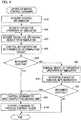
FIG. 4 , of a flow of a process carried out by themonitoring control unit 1 when the operator inputs a control command into theinput unit 4 in the plantmonitoring control device 100 according to the first embodiment. A process carried out by the operator is also included in the flowchart ofFIG. 4 (step S70). - When the operator inputs a control command into the
input unit 4, thecontrol unit 13 of themonitoring control unit 1 acquires control information from the input control command in step 10 (S10). Continuing, in step 20 (S20), thecontrol unit 13 notifies thesimulator 2 of the acquired control information, and requests a predictive operation of thesimulator 2. - The
simulator 2, on receiving the predictive operation request, executes thecontrol program 21 using the control information notified of by thecontrol unit 13 and the plant data (calculated values) acquired from theplant model 3. A flow of a process carried out by thesimulator 2 will be described hereafter using a flowchart ofFIG. 5 . - In step 30 (S30), the
control unit 13 acquires a predictive operation result from thesimulator 2. Continuing, in step 40 (S40), thecontrol unit 13 notifies thedetermination circuit 131 of the predictive operation result, and whether or not to implement the current control is determined in thedetermination circuit 131. - When the
determination circuit 131 determines in step 50 (S50) to implement the current control (YES), the process proceeds to step 90 (S90), and thecontrol unit 13 notifies the input/output processing unit 11 of the control information in the current control command, and commands the control. Furthermore, in step 100 (S100), the input/output processing unit 11 notifies theprocess control device 300 of the control information in the current control command, and commands the control. - Meanwhile, when the
determination circuit 131 determines instep 50 not to implement the current control (NO), the process proceeds to step 60 (S60), and thecontrol unit 13 displays the result of the predictive operation by thesimulator 2 and the result of the determination by thedetermination circuit 131 in thedisplay unit 5. Continuing, in step 70 (S70), the operator refers to the result of the predictive operation by thesimulator 2 displayed in thedisplay unit 5, and considers whether to implement the current control. - When the operator determines in step 80 (S80) to implement the current control (YES), the control unit executes the processes of S90 and S100. Also, when the operator determines in
step 80 not to implement the current control (NO), the process is ended. - Next, a flow of a process carried out by the
simulator 2 will be described using the flowchart ofFIG. 5 . Thesimulator 2 executes an operation every fixed cycle (for example, 50 msec to 500 msec). When starting an operation, firstly, thesimulator 2 confirms in step 200 (S200) whether or not there is a predictive operation request from thecontrol unit 13. The existence or otherwise of a predictive operation request is determined by the existence or otherwise of a notification of control information. - When there is no predictive operation request in step 210 (S210) (NO), the process proceeds to step 220 (S220), and the
simulator 2 acquires actual plant data (current values) from theprocess control device 300. Continuing, in step 221 (S221), thesimulator 2 executes thecontrol program 21 using the actual plant data acquired in S220. Furthermore, in step 222 (S222), thesimulator 2 notifies theplant model 3 of a predictive operation result, and carries out an operation ending process in step 240 (S240). - Meanwhile, when there is a predictive operation request in step 210 (YES), the process proceeds to step 230 (S230), and the
simulator 2 acquires plant data (calculated values) from theplant model 3. Continuing, in step 231 (S231), thesimulator 2 executes thecontrol program 21 using the plant data (calculated values) acquired in S230. Furthermore, in step 232 (S232), thesimulator 2 notifies thedetermination circuit 131 of a predictive operation result, and carries out the operation ending process in S240. - According to the plant
monitoring control device 100 according to the first embodiment, when a control command is input by the operator into theprocess control device 300 that implements control of theplant 200, thesimulator 2 is notified of control information in the control command by thecontrol unit 13. Furthermore, whether or not to implement the control is automatically determined by thedetermination circuit 131 of thecontrol unit 13 based on a result of a predictive operation by thesimulator 2, and when determining to implement, theprocess control device 300 is notified of the control information in the control command by thecontrol unit 13. - Therefore, the operator carries out no operation other than inputting a control command into the
input unit 4, and does not determine by him or herself whether or not to implement the control based on a predictive operation result, because of which an appropriate control whose result is predicted in advance by thesimulator 2 can be promptly implemented, and a burden on the operator is reduced. - In the first embodiment, when a control command from the operator is input into the
input unit 4, a predictive operation by thesimulator 2 is carried out regardless of the control process details. Among command controls, however, there are also simple processes that do not need a predictive operation. - Therefore, in a second embodiment of the invention, a predictive operation is carried out only for a control command with process details such that a predictive operation by a simulator is necessary. As an overall configuration of the plant
monitoring control device 100 according to the second embodiment is the same as in the first embodiment,FIG. 1 will be utilized, and a description of each portion omitted. - The
control unit 13 of the plantmonitoring control device 100 according to the second embodiment has a predictive operation necessity determination table shown inFIG. 6 , and determines whether or not a control command input into theinput unit 4 is a control command such that a predictive operation by thesimulator 2 is necessary. - In the example shown in
FIG. 6 , a determination standard is provided for each control process ID in the predictive operation necessity determination table. For example, in the case of an "XX valve opening" of aprocess ID 1, thecontrol unit 13 determines that a predictive operation is necessary when a flow exceeds 100 (liters/minute). Also, in the case of an "XX valve closing" of aprocess ID 2, thecontrol unit 13 determines that no predictive operation is necessary, regardless of the flow. - A description will be given, using a flowchart of
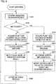
FIG. 7 , of a flow of a process carried out by themonitoring control unit 1 when the operator inputs a control command into theinput unit 4 in the plantmonitoring control device 100 according to the second embodiment. A process carried out by the operator is also included in the flowchart ofFIG. 7 (step S70). - When the operator inputs a control command into the
input unit 4, thecontrol unit 13 of themonitoring control unit 1 acquires control information from the input control command in S10, and determines in step 15 (S15) whether or not the current control command is a control command such that a predictive operation by thesimulator 2 is necessary. Specifically, thecontrol unit 13 refers to the process ID corresponding to the control information acquired in S10 in the predictive operation necessity determination table (FIG. 6 ), acquires the plant data necessary for the determination from theprocess control device 300, and carries out the determination. - When the
control unit 13 determines in S15 that a predictive operation is necessary (YES), the process proceeds to S20, and thecontrol unit 13 notifies thesimulator 2 of the control information in the current control command, and requests a predictive operation. Meanwhile, when thecontrol unit 13 determines in S15 that no predictive operation is necessary (NO), the process proceeds to S90, and thecontrol unit 13 notifies the input/output processing unit 11 of the control information in the current control command, and commands the control. - Furthermore, in S100, the input/
output processing unit 11 notifies theprocess control device 300 of the control information in the current control command, and commands the control. As the processes of S30 to S80 are the same processes as in the flowchart ofFIG. 4 described in the first embodiment, a description thereof will be omitted. - According to the second embodiment, in addition to the same advantages as in the first embodiment, a control command for which it is determined that no predictive operation is necessary is such that the
process control device 300 is notified directly of the control information without a predictive operation being carried out by thesimulator 2, because of which a simple control can be implemented promptly, and the burden on the operator is reduced. - In the first embodiment, the
determination circuit 131 and determinationlogic storage unit 132 for determining whether or not to implement the current control are provided in thecontrol unit 13, but in a third embodiment of the invention, a determination unit is provided together with determination logic as one portion of thecontrol program 21 executed by thesimulator 2. As an overall configuration of the plantmonitoring control device 100 according to the third embodiment is the same as in the first embodiment,FIG. 1 will be utilized, and a description of each portion omitted. FIG. 8 is a flowchart showing a flow of a process carried out by thesimulator 2 in the third embodiment. InFIG. 8 , the processes of S200 to S231 are the same processes as in the flowchart ofFIG. 5 described in the first embodiment, because of which a description thereof will be omitted.- In S231, the
simulator 2 executes thecontrol program 21 using the plant data (calculated values) acquired in S230, and carries out a predictive operation. Continuing, in step 233 (S233), thesimulator 2 determines in thecontrol program 21, based on a result of the predictive operation, whether or not to implement the current control. Subsequently, in step 234 (S234), thesimulator 2 notifies thecontrol unit 13 of the result of the predictive operation and the determination result, and carries out an operation ending process in S240. - In this way, in the third embodiment, the
control unit 13 acquires a result of a predictive operation and a result of determining whether or not to implement the current control from thesimulator 2. When thesimulator 2 determines to implement the current control, thecontrol unit 13 notifies theprocess control device 300 of the control information in the current control command, and theprocess control device 300 implements a control based on the current control command. - Meanwhile, when the
simulator 2 determines not to implement the current control, thecontrol unit 13 displays a result of a predictive operation by thesimulator 2 and the determination result in thedisplay unit 5, and the operator refers to the result of the predictive operation by thesimulator 2 displayed in thedisplay unit 5, and considers whether to implement the current control. - According to the third embodiment, in addition to the same advantages as in the first embodiment, determination logic can be programmed by a determination unit being one portion of the
control program 21 of thesimulator 2, whereby more complex determination logic can be set. - In the first embodiment to third embodiment, when a determination unit determines from a result of a predictive operation by the
simulator 2 not to implement the current control, the operator has to refer to the result of the predictive operation by thesimulator 2 displayed in thedisplay unit 5, consider whether to implement the current control, and command the next control. - Therefore, in a fourth embodiment of the invention, there is an additional function that presents the operator with operational guidance relating to the next control when a determination unit determines not to implement the current control. As an overall configuration of the plant
monitoring control device 100 according to the fourth embodiment is the same as in the first embodiment,FIG. 1 will be utilized, and a description of each portion omitted. Also, in the fourth embodiment, the determination unit is provided as one portion of thecontrol program 21 of thesimulator 2, in the same way as in the third embodiment. - By a certain control being implemented with respect to the
plant 200, there is an expected change in a plant state (plant data) (this is referred to as an expected advantage). For example, when the "XX valve opening" ofprocess ID 1 shown inFIG. 6 is implemented, a change in the plant data, that being an xx level rise or an xx flow increase, is expected at a normal time. At an abnormal time, however, there are cases in which the expected advantage is not obtained even though the control is implemented, and also cases in which the control itself cannot be implemented. - When it is predicted as a result of a predictive operation by the
simulator 2 that the expected advantage will not be obtained, and the determination unit determines not to implement the current control, the operator needs to command another control in place of the current control. Themonitoring unit 12 in the fourth embodiment has an operational guidance storage unit and operational guidance search means (both omitted from the drawing), and the operator can issue the next control command by referring to operational guidance displayed in thedisplay unit 5. - Operational guidance is stored in the operational guidance storage unit. Operational guidance is configured to include each control process ID, process details, the expected advantage of the process, a substitute process, and the like. For example, when the expected advantage when implementing the "XX valve opening" of
process ID 1 is an "xx flow increase", a "YY valve opening" is registered as a substitute process for obtaining the "xx flow increase". The operational guidance search means searches for operational guidance based on the current control process ID, and extracts a substitute process. - A description will be given, using a flowchart of
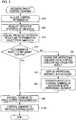
FIG. 9 , of a flow of a process carried out by themonitoring control unit 1 when the operator inputs a control command into theinput unit 4 in the plantmonitoring control device 100 according to the fourth embodiment. InFIG. 9 , the processes of S10, S20, S90, and S100 are the same processes as in the flowchart ofFIG. 4 described in the first embodiment. A process carried out by the operator is also included in the flowchart ofFIG. 9 (step S81). - When the operator inputs a control command into the
input unit 4, thecontrol unit 13 acquires control information from the input control command in S10. Continuing, in S20, thecontrol unit 13 notifies thesimulator 2 of the acquired control information, and requests a predictive operation of thesimulator 2. Thesimulator 2, on receiving the predictive operation request, executes thecontrol program 21 using the control information notified of by thecontrol unit 13 and the plant data (calculated values) acquired from theplant model 3, and determines whether or not to implement the current control based on a result of the predictive operation. - Continuing, in step 31 (S31), the
control unit 13 acquires the predictive operation result and determination result from thesimulator 2. When the determination result in step 51 (S51) is that the current control is to be implemented (YES), the process proceeds to S90, thecontrol unit 13 commands the input/output processing unit 11 to implement the current control, and furthermore, in S100, the input/output processing unit 11 commands theprocess control device 300 to implement the current control. - Meanwhile, when the determination result in S51 is that the current control is not to be implemented (NO), the operational guidance search unit of the
monitoring unit 12 searches for operational guidance from the category (process ID) of the current control and the predictive operation result in step 61 (S61), and displays the operational guidance in thedisplay unit 5 in step 71 (S71). Continuing, in step 81 (S81), the operator inputs the next control command into theinput unit 4 in accordance with the operational guidance, and the processes of S90 and S100 are carried out. - According to the fourth embodiment, in addition to the same advantages as in the first embodiment and third embodiment, the operator is presented with operational guidance relating to the next control when the determination unit determines not to implement the current control, because of which the burden on the operator is further reduced, and an appropriate control can also be implemented promptly at an abnormal time in the
plant 200. The embodiments can be freely combined, and each embodiment can be modified or abbreviated as appropriate, without departing from the scope of the appended set of claims.
Claims (6)
- A plant monitoring control device, connected via a network (40) to a process control device (300) that is configured to implement control of a plant (200) based on control information, that is configured to carry out monitoring control by acquiring plant data, which are various kinds of parameter indicating a state of the plant (200), from the process control device (300),
the plant monitoring control device comprising:- an input unit (4) into which a control command for the process control device (300) is input;- a simulator (2) that is configured to execute a control program (21) that simulates an operation of the process control device (300) and is configured to carry out an operation predicting plant data after a control based on the control command is implemented;- a plant model (3), having a database (31) in which are accumulated plant data acquired from the process control device (300), that is configured to supply plant data necessary when executing the control program (21) to the simulator (2);- a determination unit including a determination logic storage unit (132) configured to store determination logic set with respect to process details of each control of the plant (200);
wherein the determination unit is configured to acquire predicted plant data that are a result of a predictive operation by the simulator (2), and the determination unit comprises a determination circuit (131) configured to determine, based on the predicted plant data acquired from the simulator (2) and the determination logic set stored in the determination logic storage unit (132), whether or not to implement a control based on the control command; and- a control unit (13) that is configured to notify the simulator (2) of control information in the control command and to request the predictive operation, and is configured to notify the process control device (300) of the control information in the control command when the determination unit determines to implement a control based on the control command, wherein the control unit (13) is configured to have a predictive operation necessity determination table, and is configured to determine using the predictive operation necessity determination table whether or not a control command input into the input unit (4) is a control command for which a predictive operation by the simulator (2) is necessary, to notify the simulator (2) of control information in the control command and to request a predictive operation when determining that a predictive operation is necessary, and to notify the process control device (300) of the control information in the control command when determining that no predictive operation is necessary. - The plant monitoring control device according to claim 1,
wherein the plant model (3) is configured to acquire predicted plant data that are a result of the predictive operation by the simulator (2) and actual plant data corresponding to the predicted plant data, to compare the two, and when a gap between the two is equal to or greater than a predetermined value, is configured to correct plant data supplied to the simulator (2), thereby updating the database (31). - The plant monitoring control device according to claims 1 or 2, comprising:an operational guidance storage unit configured to store process details of each control, an expected advantage of the process, and a substitute process for obtaining the expected advantage, wherein the expected advantage is an expected change in the state of the plant (200) when a certain control of the plant (200) is implemented;operational guidance search means that is configured to search the operational guidance storage unit based on the process details of a current control and to extract a substitute process; and a display unit (5) that is configured to display operational guidance, wherein,when the determination unit determines not to implement a control based on a current control command, the operational guidance search means is configured to extract a substitute process of a control based on the current control command, and to display the substitute process in the display unit (5) as operational guidance.
- The plant monitoring control device according to claim 1,
wherein the control unit (13) of the monitoring control unit (1) is configured to acquire control information from the input control command, and to determine whether or not the current control command is a control command such that the predictive operation by the simulator (2) is necessary using the predictive operation necessity determination table, when a control command is input into the input unit (4). - The plant monitoring control device according to claim 1 or 4,
wherein the control unit (13) is configured to refer to a process ID corresponding to the control information in the predictive operation necessity determination table, acquire the plant data necessary for the determination from the process control device (300), and carry out the determination. - The plant monitoring control device according to any of claims 1, 4 or 5, wherein notifying the process control device (300) when the control unit (13) determines that no predictive operation is necessary, is performed by the control unit (13) notifying an input/output processing unit (11) of the control information in the current control command, wherein, the input/output processing unit (11) is configured to notify the process control device (300) of the control information in the current control command, and to command the control.
Applications Claiming Priority (1)
| Application Number | Priority Date | Filing Date | Title |
|---|---|---|---|
| PCT/JP2015/058820WO2016151744A1 (en) | 2015-03-24 | 2015-03-24 | Plant monitor/control device |
Publications (3)
| Publication Number | Publication Date |
|---|---|
| EP3276436A1 EP3276436A1 (en) | 2018-01-31 |
| EP3276436A4 EP3276436A4 (en) | 2019-01-16 |
| EP3276436B1true EP3276436B1 (en) | 2021-07-28 |
Family
ID=55362177
Family Applications (1)
| Application Number | Title | Priority Date | Filing Date |
|---|---|---|---|
| EP15886297.9AActiveEP3276436B1 (en) | 2015-03-24 | 2015-03-24 | Plant monitor/control device |
Country Status (5)
| Country | Link |
|---|---|
| US (1) | US10216154B2 (en) |
| EP (1) | EP3276436B1 (en) |
| JP (1) | JP5872124B1 (en) |
| CN (1) | CN107407914B (en) |
| WO (1) | WO2016151744A1 (en) |
Families Citing this family (7)
| Publication number | Priority date | Publication date | Assignee | Title |
|---|---|---|---|---|
| JP6683746B2 (en) | 2018-02-08 | 2020-04-22 | ファナック株式会社 | Monitoring device and monitoring method |
| WO2019234913A1 (en)* | 2018-06-08 | 2019-12-12 | 千代田化工建設株式会社 | Assistance device, learning device, and plant operation condition setting assistance system |
| KR102215513B1 (en)* | 2018-09-05 | 2021-02-15 | 두산중공업 주식회사 | Plant Monitoring Method Using Exergy Efficiency Value |
| JP7276204B2 (en)* | 2020-03-06 | 2023-05-18 | 横河電機株式会社 | Information processing device, information processing method, and program |
| JP7059346B1 (en) | 2020-12-22 | 2022-04-25 | 東芝プラントシステム株式会社 | Plant simulation equipment and plant simulation system |
| CN116670597A (en)* | 2020-12-28 | 2023-08-29 | 东京毅力科创株式会社 | Management device, prediction method, and prediction program |
| KR102594827B1 (en)* | 2021-01-20 | 2023-10-26 | 한국수력원자력 주식회사 | A system that predicts operation for multiple devices |
Family Cites Families (20)
| Publication number | Priority date | Publication date | Assignee | Title |
|---|---|---|---|---|
| JPH05119191A (en)* | 1991-10-28 | 1993-05-18 | Mitsubishi Heavy Ind Ltd | Operation support device |
| US6408227B1 (en)* | 1999-09-29 | 2002-06-18 | The University Of Iowa Research Foundation | System and method for controlling effluents in treatment systems |
| JP2001290516A (en)* | 2000-04-10 | 2001-10-19 | Toshiba Corp | Monitoring control system, control device simulation method, and storage medium |
| US9983559B2 (en)* | 2002-10-22 | 2018-05-29 | Fisher-Rosemount Systems, Inc. | Updating and utilizing dynamic process simulation in an operating process environment |
| US7515977B2 (en)* | 2004-03-30 | 2009-04-07 | Fisher-Rosemount Systems, Inc. | Integrated configuration system for use in a process plant |
| JP4789277B2 (en)* | 2004-04-22 | 2011-10-12 | 横河電機株式会社 | Plant operation support device |
| DE602005015220D1 (en)* | 2005-09-16 | 2009-08-13 | Mettler Toledo Ag | Method for simulating a process on a laboratory scale |
| NO323949B1 (en)* | 2005-10-31 | 2007-07-23 | Marine Cybernetics As | Method and system for testing a regulatory system for a marine petroleum processing plant |
| CN104834294A (en)* | 2005-12-05 | 2015-08-12 | 费舍-柔斯芒特系统股份有限公司 | Muti-objective predictive process optimization with concurrent process simulation |
| CN101799661B (en) | 2007-01-10 | 2012-12-05 | 株式会社日立制作所 | Control device for boiler plant and device for training operator of boiler plant |
| JP4423617B2 (en)* | 2007-01-10 | 2010-03-03 | 株式会社日立製作所 | Plant control device |
| CN101842756A (en)* | 2007-08-14 | 2010-09-22 | 国际壳牌研究有限公司 | System and method for continuous, on-line monitoring of a chemical plant or refinery |
| JP2009223457A (en) | 2008-03-14 | 2009-10-01 | Yokogawa Electric Corp | Plant operation support device |
| JPWO2011004454A1 (en)* | 2009-07-07 | 2012-12-13 | 新日本製鐵株式会社 | Operation support device, operation support method and program |
| US9043003B2 (en)* | 2009-07-31 | 2015-05-26 | Fisher-Rosemount Systems, Inc. | Graphical view sidebar for a process control system |
| JP5698576B2 (en)* | 2010-03-23 | 2015-04-08 | メタウォーター株式会社 | Graph editing simulation device, graph editing simulation program, and plant maintenance management system |
| JP5854856B2 (en)* | 2012-01-24 | 2016-02-09 | 三菱電機株式会社 | Plant operation device and plant operation training simulator device |
| ITCO20120008A1 (en)* | 2012-03-01 | 2013-09-02 | Nuovo Pignone Srl | METHOD AND SYSTEM FOR MONITORING THE CONDITION OF A GROUP OF PLANTS |
| US9423780B2 (en) | 2012-10-19 | 2016-08-23 | Youtech, Inc. | Handheld device for preventing misoperations in an electric power system |
| JP6173418B2 (en)* | 2015-12-15 | 2017-08-02 | 三菱電機ビルテクノサービス株式会社 | Surveillance system simulator |
- 2015
- 2015-03-24EPEP15886297.9Apatent/EP3276436B1/enactiveActive
- 2015-03-24CNCN201580078116.XApatent/CN107407914B/ennot_activeExpired - Fee Related
- 2015-03-24USUS15/560,566patent/US10216154B2/ennot_activeExpired - Fee Related
- 2015-03-24JPJP2015542076Apatent/JP5872124B1/ennot_activeExpired - Fee Related
- 2015-03-24WOPCT/JP2015/058820patent/WO2016151744A1/ennot_activeCeased
Non-Patent Citations (1)
| Title |
|---|
| None* |
Also Published As
| Publication number | Publication date |
|---|---|
| EP3276436A4 (en) | 2019-01-16 |
| US10216154B2 (en) | 2019-02-26 |
| US20180046154A1 (en) | 2018-02-15 |
| WO2016151744A1 (en) | 2016-09-29 |
| JPWO2016151744A1 (en) | 2017-04-27 |
| JP5872124B1 (en) | 2016-03-01 |
| CN107407914B (en) | 2020-10-16 |
| CN107407914A (en) | 2017-11-28 |
| EP3276436A1 (en) | 2018-01-31 |
Similar Documents
| Publication | Publication Date | Title |
|---|---|---|
| EP3276436B1 (en) | Plant monitor/control device | |
| US10956238B2 (en) | Programmable controller, management device, and control system | |
| KR20150077475A (en) | Program creation assistance device, method and recording medium | |
| CN114454197B (en) | Remote control method, device, equipment and medium for disinfection robot | |
| EP3223146A1 (en) | Hmi system | |
| JP5669987B1 (en) | Control device, development device, and development program | |
| US8910050B2 (en) | Manipulation-monitoring device | |
| EP2853968A1 (en) | An alarm management system and a method therefor | |
| CN103455382B (en) | Processor running frequency control method and system | |
| CN108121261A (en) | For showing the method for monitor screen | |
| US10061686B2 (en) | Method, electronic apparatus, system, and storage medium for automated testing of application user interface | |
| JP5495630B2 (en) | Work procedure management system | |
| EP3336630A1 (en) | Nc program transfer apparatus | |
| JP2015141719A (en) | Method for usage-controlled updating of software product | |
| JP2023539376A (en) | Method for controlling virtual assistant for industrial plants | |
| TW200302426A (en) | Man-machine interface to monitor and control a processing system | |
| CN111857055A (en) | Machining support device, numerical controller, and machining support system | |
| JP2017187964A (en) | Numerical controller for improving production process | |
| JP2021093115A (en) | Method and apparatus for processing local hot spot, electronic device and storage medium | |
| CN114641735A (en) | System and method for managing drive components | |
| US10935965B2 (en) | Operation management apparatus | |
| JP6109438B1 (en) | System design support apparatus, method and program | |
| US10402730B2 (en) | Method and system for determining whether, when, and how an unmanned agent interrupts a human | |
| JPWO2020202464A1 (en) | Monitoring control terminal device and screen display method | |
| CN113728286A (en) | Screen data generation system, screen data generation method, and program |
Legal Events
| Date | Code | Title | Description |
|---|---|---|---|
| STAA | Information on the status of an ep patent application or granted ep patent | Free format text:STATUS: THE INTERNATIONAL PUBLICATION HAS BEEN MADE | |
| PUAI | Public reference made under article 153(3) epc to a published international application that has entered the european phase | Free format text:ORIGINAL CODE: 0009012 | |
| STAA | Information on the status of an ep patent application or granted ep patent | Free format text:STATUS: REQUEST FOR EXAMINATION WAS MADE | |
| 17P | Request for examination filed | Effective date:20170921 | |
| AK | Designated contracting states | Kind code of ref document:A1 Designated state(s):AL AT BE BG CH CY CZ DE DK EE ES FI FR GB GR HR HU IE IS IT LI LT LU LV MC MK MT NL NO PL PT RO RS SE SI SK SM TR | |
| AX | Request for extension of the european patent | Extension state:BA ME | |
| DAV | Request for validation of the european patent (deleted) | ||
| DAX | Request for extension of the european patent (deleted) | ||
| REG | Reference to a national code | Ref country code:DE Ref legal event code:R079 Ref document number:602015071813 Country of ref document:DE Free format text:PREVIOUS MAIN CLASS: G05B0017020000 Ipc:G05B0013040000 | |
| A4 | Supplementary search report drawn up and despatched | Effective date:20181217 | |
| RIC1 | Information provided on ipc code assigned before grant | Ipc:G05B 13/04 20060101AFI20181211BHEP Ipc:G05B 23/02 20060101ALI20181211BHEP Ipc:G05B 17/02 20060101ALI20181211BHEP | |
| STAA | Information on the status of an ep patent application or granted ep patent | Free format text:STATUS: EXAMINATION IS IN PROGRESS | |
| 17Q | First examination report despatched | Effective date:20191024 | |
| GRAP | Despatch of communication of intention to grant a patent | Free format text:ORIGINAL CODE: EPIDOSNIGR1 | |
| STAA | Information on the status of an ep patent application or granted ep patent | Free format text:STATUS: GRANT OF PATENT IS INTENDED | |
| INTG | Intention to grant announced | Effective date:20200901 | |
| GRAJ | Information related to disapproval of communication of intention to grant by the applicant or resumption of examination proceedings by the epo deleted | Free format text:ORIGINAL CODE: EPIDOSDIGR1 | |
| STAA | Information on the status of an ep patent application or granted ep patent | Free format text:STATUS: EXAMINATION IS IN PROGRESS | |
| GRAP | Despatch of communication of intention to grant a patent | Free format text:ORIGINAL CODE: EPIDOSNIGR1 | |
| STAA | Information on the status of an ep patent application or granted ep patent | Free format text:STATUS: GRANT OF PATENT IS INTENDED | |
| INTC | Intention to grant announced (deleted) | ||
| INTG | Intention to grant announced | Effective date:20210210 | |
| GRAS | Grant fee paid | Free format text:ORIGINAL CODE: EPIDOSNIGR3 | |
| GRAA | (expected) grant | Free format text:ORIGINAL CODE: 0009210 | |
| STAA | Information on the status of an ep patent application or granted ep patent | Free format text:STATUS: THE PATENT HAS BEEN GRANTED | |
| AK | Designated contracting states | Kind code of ref document:B1 Designated state(s):AL AT BE BG CH CY CZ DE DK EE ES FI FR GB GR HR HU IE IS IT LI LT LU LV MC MK MT NL NO PL PT RO RS SE SI SK SM TR | |
| REG | Reference to a national code | Ref country code:GB Ref legal event code:FG4D | |
| REG | Reference to a national code | Ref country code:CH Ref legal event code:EP | |
| REG | Reference to a national code | Ref country code:AT Ref legal event code:REF Ref document number:1415252 Country of ref document:AT Kind code of ref document:T Effective date:20210815 | |
| REG | Reference to a national code | Ref country code:IE Ref legal event code:FG4D | |
| REG | Reference to a national code | Ref country code:DE Ref legal event code:R096 Ref document number:602015071813 Country of ref document:DE | |
| REG | Reference to a national code | Ref country code:LT Ref legal event code:MG9D | |
| REG | Reference to a national code | Ref country code:NL Ref legal event code:MP Effective date:20210728 | |
| REG | Reference to a national code | Ref country code:AT Ref legal event code:MK05 Ref document number:1415252 Country of ref document:AT Kind code of ref document:T Effective date:20210728 | |
| PG25 | Lapsed in a contracting state [announced via postgrant information from national office to epo] | Ref country code:AT Free format text:LAPSE BECAUSE OF FAILURE TO SUBMIT A TRANSLATION OF THE DESCRIPTION OR TO PAY THE FEE WITHIN THE PRESCRIBED TIME-LIMIT Effective date:20210728 Ref country code:BG Free format text:LAPSE BECAUSE OF FAILURE TO SUBMIT A TRANSLATION OF THE DESCRIPTION OR TO PAY THE FEE WITHIN THE PRESCRIBED TIME-LIMIT Effective date:20211028 Ref country code:LT Free format text:LAPSE BECAUSE OF FAILURE TO SUBMIT A TRANSLATION OF THE DESCRIPTION OR TO PAY THE FEE WITHIN THE PRESCRIBED TIME-LIMIT Effective date:20210728 Ref country code:PT Free format text:LAPSE BECAUSE OF FAILURE TO SUBMIT A TRANSLATION OF THE DESCRIPTION OR TO PAY THE FEE WITHIN THE PRESCRIBED TIME-LIMIT Effective date:20211129 Ref country code:NO Free format text:LAPSE BECAUSE OF FAILURE TO SUBMIT A TRANSLATION OF THE DESCRIPTION OR TO PAY THE FEE WITHIN THE PRESCRIBED TIME-LIMIT Effective date:20211028 Ref country code:NL Free format text:LAPSE BECAUSE OF FAILURE TO SUBMIT A TRANSLATION OF THE DESCRIPTION OR TO PAY THE FEE WITHIN THE PRESCRIBED TIME-LIMIT Effective date:20210728 Ref country code:ES Free format text:LAPSE BECAUSE OF FAILURE TO SUBMIT A TRANSLATION OF THE DESCRIPTION OR TO PAY THE FEE WITHIN THE PRESCRIBED TIME-LIMIT Effective date:20210728 Ref country code:FI Free format text:LAPSE BECAUSE OF FAILURE TO SUBMIT A TRANSLATION OF THE DESCRIPTION OR TO PAY THE FEE WITHIN THE PRESCRIBED TIME-LIMIT Effective date:20210728 Ref country code:SE Free format text:LAPSE BECAUSE OF FAILURE TO SUBMIT A TRANSLATION OF THE DESCRIPTION OR TO PAY THE FEE WITHIN THE PRESCRIBED TIME-LIMIT Effective date:20210728 Ref country code:RS Free format text:LAPSE BECAUSE OF FAILURE TO SUBMIT A TRANSLATION OF THE DESCRIPTION OR TO PAY THE FEE WITHIN THE PRESCRIBED TIME-LIMIT Effective date:20210728 Ref country code:HR Free format text:LAPSE BECAUSE OF FAILURE TO SUBMIT A TRANSLATION OF THE DESCRIPTION OR TO PAY THE FEE WITHIN THE PRESCRIBED TIME-LIMIT Effective date:20210728 | |
| PG25 | Lapsed in a contracting state [announced via postgrant information from national office to epo] | Ref country code:PL Free format text:LAPSE BECAUSE OF FAILURE TO SUBMIT A TRANSLATION OF THE DESCRIPTION OR TO PAY THE FEE WITHIN THE PRESCRIBED TIME-LIMIT Effective date:20210728 Ref country code:LV Free format text:LAPSE BECAUSE OF FAILURE TO SUBMIT A TRANSLATION OF THE DESCRIPTION OR TO PAY THE FEE WITHIN THE PRESCRIBED TIME-LIMIT Effective date:20210728 Ref country code:GR Free format text:LAPSE BECAUSE OF FAILURE TO SUBMIT A TRANSLATION OF THE DESCRIPTION OR TO PAY THE FEE WITHIN THE PRESCRIBED TIME-LIMIT Effective date:20211029 | |
| PG25 | Lapsed in a contracting state [announced via postgrant information from national office to epo] | Ref country code:DK Free format text:LAPSE BECAUSE OF FAILURE TO SUBMIT A TRANSLATION OF THE DESCRIPTION OR TO PAY THE FEE WITHIN THE PRESCRIBED TIME-LIMIT Effective date:20210728 | |
| REG | Reference to a national code | Ref country code:DE Ref legal event code:R097 Ref document number:602015071813 Country of ref document:DE | |
| PG25 | Lapsed in a contracting state [announced via postgrant information from national office to epo] | Ref country code:SM Free format text:LAPSE BECAUSE OF FAILURE TO SUBMIT A TRANSLATION OF THE DESCRIPTION OR TO PAY THE FEE WITHIN THE PRESCRIBED TIME-LIMIT Effective date:20210728 Ref country code:SK Free format text:LAPSE BECAUSE OF FAILURE TO SUBMIT A TRANSLATION OF THE DESCRIPTION OR TO PAY THE FEE WITHIN THE PRESCRIBED TIME-LIMIT Effective date:20210728 Ref country code:RO Free format text:LAPSE BECAUSE OF FAILURE TO SUBMIT A TRANSLATION OF THE DESCRIPTION OR TO PAY THE FEE WITHIN THE PRESCRIBED TIME-LIMIT Effective date:20210728 Ref country code:EE Free format text:LAPSE BECAUSE OF FAILURE TO SUBMIT A TRANSLATION OF THE DESCRIPTION OR TO PAY THE FEE WITHIN THE PRESCRIBED TIME-LIMIT Effective date:20210728 Ref country code:CZ Free format text:LAPSE BECAUSE OF FAILURE TO SUBMIT A TRANSLATION OF THE DESCRIPTION OR TO PAY THE FEE WITHIN THE PRESCRIBED TIME-LIMIT Effective date:20210728 Ref country code:AL Free format text:LAPSE BECAUSE OF FAILURE TO SUBMIT A TRANSLATION OF THE DESCRIPTION OR TO PAY THE FEE WITHIN THE PRESCRIBED TIME-LIMIT Effective date:20210728 | |
| PLBE | No opposition filed within time limit | Free format text:ORIGINAL CODE: 0009261 | |
| STAA | Information on the status of an ep patent application or granted ep patent | Free format text:STATUS: NO OPPOSITION FILED WITHIN TIME LIMIT | |
| 26N | No opposition filed | Effective date:20220429 | |
| PG25 | Lapsed in a contracting state [announced via postgrant information from national office to epo] | Ref country code:IT Free format text:LAPSE BECAUSE OF FAILURE TO SUBMIT A TRANSLATION OF THE DESCRIPTION OR TO PAY THE FEE WITHIN THE PRESCRIBED TIME-LIMIT Effective date:20210728 | |
| REG | Reference to a national code | Ref country code:DE Ref legal event code:R119 Ref document number:602015071813 Country of ref document:DE | |
| PG25 | Lapsed in a contracting state [announced via postgrant information from national office to epo] | Ref country code:MC Free format text:LAPSE BECAUSE OF FAILURE TO SUBMIT A TRANSLATION OF THE DESCRIPTION OR TO PAY THE FEE WITHIN THE PRESCRIBED TIME-LIMIT Effective date:20210728 | |
| REG | Reference to a national code | Ref country code:CH Ref legal event code:PL | |
| GBPC | Gb: european patent ceased through non-payment of renewal fee | Effective date:20220324 | |
| REG | Reference to a national code | Ref country code:BE Ref legal event code:MM Effective date:20220331 | |
| PG25 | Lapsed in a contracting state [announced via postgrant information from national office to epo] | Ref country code:LU Free format text:LAPSE BECAUSE OF NON-PAYMENT OF DUE FEES Effective date:20220324 Ref country code:LI Free format text:LAPSE BECAUSE OF NON-PAYMENT OF DUE FEES Effective date:20220331 Ref country code:IE Free format text:LAPSE BECAUSE OF NON-PAYMENT OF DUE FEES Effective date:20220324 Ref country code:GB Free format text:LAPSE BECAUSE OF NON-PAYMENT OF DUE FEES Effective date:20220324 Ref country code:FR Free format text:LAPSE BECAUSE OF NON-PAYMENT OF DUE FEES Effective date:20220331 Ref country code:DE Free format text:LAPSE BECAUSE OF NON-PAYMENT OF DUE FEES Effective date:20221001 Ref country code:CH Free format text:LAPSE BECAUSE OF NON-PAYMENT OF DUE FEES Effective date:20220331 | |
| PG25 | Lapsed in a contracting state [announced via postgrant information from national office to epo] | Ref country code:BE Free format text:LAPSE BECAUSE OF NON-PAYMENT OF DUE FEES Effective date:20220331 | |
| PGFP | Annual fee paid to national office [announced via postgrant information from national office to epo] | Ref country code:TR Payment date:20230322 Year of fee payment:9 | |
| PG25 | Lapsed in a contracting state [announced via postgrant information from national office to epo] | Ref country code:HU Free format text:LAPSE BECAUSE OF FAILURE TO SUBMIT A TRANSLATION OF THE DESCRIPTION OR TO PAY THE FEE WITHIN THE PRESCRIBED TIME-LIMIT; INVALID AB INITIO Effective date:20150324 | |
| PG25 | Lapsed in a contracting state [announced via postgrant information from national office to epo] | Ref country code:MK Free format text:LAPSE BECAUSE OF FAILURE TO SUBMIT A TRANSLATION OF THE DESCRIPTION OR TO PAY THE FEE WITHIN THE PRESCRIBED TIME-LIMIT Effective date:20210728 Ref country code:CY Free format text:LAPSE BECAUSE OF FAILURE TO SUBMIT A TRANSLATION OF THE DESCRIPTION OR TO PAY THE FEE WITHIN THE PRESCRIBED TIME-LIMIT Effective date:20210728 | |
| PG25 | Lapsed in a contracting state [announced via postgrant information from national office to epo] | Ref country code:MT Free format text:LAPSE BECAUSE OF FAILURE TO SUBMIT A TRANSLATION OF THE DESCRIPTION OR TO PAY THE FEE WITHIN THE PRESCRIBED TIME-LIMIT Effective date:20210728 |