EP3273854B1 - Systems for computer-aided surgery using intra-operative video acquired by a free moving camera - Google Patents
Systems for computer-aided surgery using intra-operative video acquired by a free moving cameraDownload PDFInfo
- Publication number
- EP3273854B1 EP3273854B1EP16769785.3AEP16769785AEP3273854B1EP 3273854 B1EP3273854 B1EP 3273854B1EP 16769785 AEP16769785 AEP 16769785AEP 3273854 B1EP3273854 B1EP 3273854B1
- Authority
- EP
- European Patent Office
- Prior art keywords
- camera
- coordinates
- image
- surgical
- calibration
- Prior art date
- Legal status (The legal status is an assumption and is not a legal conclusion. Google has not performed a legal analysis and makes no representation as to the accuracy of the status listed.)
- Active
Links
Images


Classifications
- A—HUMAN NECESSITIES
- A61—MEDICAL OR VETERINARY SCIENCE; HYGIENE
- A61B—DIAGNOSIS; SURGERY; IDENTIFICATION
- A61B34/00—Computer-aided surgery; Manipulators or robots specially adapted for use in surgery
- A61B34/20—Surgical navigation systems; Devices for tracking or guiding surgical instruments, e.g. for frameless stereotaxis
- A—HUMAN NECESSITIES
- A61—MEDICAL OR VETERINARY SCIENCE; HYGIENE
- A61B—DIAGNOSIS; SURGERY; IDENTIFICATION
- A61B34/00—Computer-aided surgery; Manipulators or robots specially adapted for use in surgery
- A61B34/10—Computer-aided planning, simulation or modelling of surgical operations
- A—HUMAN NECESSITIES
- A61—MEDICAL OR VETERINARY SCIENCE; HYGIENE
- A61B—DIAGNOSIS; SURGERY; IDENTIFICATION
- A61B34/00—Computer-aided surgery; Manipulators or robots specially adapted for use in surgery
- A61B34/25—User interfaces for surgical systems
- A—HUMAN NECESSITIES
- A61—MEDICAL OR VETERINARY SCIENCE; HYGIENE
- A61B—DIAGNOSIS; SURGERY; IDENTIFICATION
- A61B34/00—Computer-aided surgery; Manipulators or robots specially adapted for use in surgery
- A61B34/30—Surgical robots
- A—HUMAN NECESSITIES
- A61—MEDICAL OR VETERINARY SCIENCE; HYGIENE
- A61B—DIAGNOSIS; SURGERY; IDENTIFICATION
- A61B90/00—Instruments, implements or accessories specially adapted for surgery or diagnosis and not covered by any of the groups A61B1/00 - A61B50/00, e.g. for luxation treatment or for protecting wound edges
- A61B90/36—Image-producing devices or illumination devices not otherwise provided for
- A61B90/361—Image-producing devices, e.g. surgical cameras
- G—PHYSICS
- G06—COMPUTING OR CALCULATING; COUNTING
- G06F—ELECTRIC DIGITAL DATA PROCESSING
- G06F3/00—Input arrangements for transferring data to be processed into a form capable of being handled by the computer; Output arrangements for transferring data from processing unit to output unit, e.g. interface arrangements
- G06F3/01—Input arrangements or combined input and output arrangements for interaction between user and computer
- G06F3/03—Arrangements for converting the position or the displacement of a member into a coded form
- G06F3/0304—Detection arrangements using opto-electronic means
- G06F3/0317—Detection arrangements using opto-electronic means in co-operation with a patterned surface, e.g. absolute position or relative movement detection for an optical mouse or pen positioned with respect to a coded surface
- G06F3/0321—Detection arrangements using opto-electronic means in co-operation with a patterned surface, e.g. absolute position or relative movement detection for an optical mouse or pen positioned with respect to a coded surface by optically sensing the absolute position with respect to a regularly patterned surface forming a passive digitiser, e.g. pen optically detecting position indicative tags printed on a paper sheet
- G—PHYSICS
- G06—COMPUTING OR CALCULATING; COUNTING
- G06T—IMAGE DATA PROCESSING OR GENERATION, IN GENERAL
- G06T19/00—Manipulating 3D models or images for computer graphics
- G06T19/006—Mixed reality
- G—PHYSICS
- G06—COMPUTING OR CALCULATING; COUNTING
- G06T—IMAGE DATA PROCESSING OR GENERATION, IN GENERAL
- G06T7/00—Image analysis
- G06T7/50—Depth or shape recovery
- G—PHYSICS
- G06—COMPUTING OR CALCULATING; COUNTING
- G06T—IMAGE DATA PROCESSING OR GENERATION, IN GENERAL
- G06T7/00—Image analysis
- G06T7/60—Analysis of geometric attributes
- G06T7/62—Analysis of geometric attributes of area, perimeter, diameter or volume
- G—PHYSICS
- G06—COMPUTING OR CALCULATING; COUNTING
- G06T—IMAGE DATA PROCESSING OR GENERATION, IN GENERAL
- G06T7/00—Image analysis
- G06T7/70—Determining position or orientation of objects or cameras
- G06T7/73—Determining position or orientation of objects or cameras using feature-based methods
- G—PHYSICS
- G06—COMPUTING OR CALCULATING; COUNTING
- G06T—IMAGE DATA PROCESSING OR GENERATION, IN GENERAL
- G06T7/00—Image analysis
- G06T7/80—Analysis of captured images to determine intrinsic or extrinsic camera parameters, i.e. camera calibration
- G06T7/85—Stereo camera calibration
- G—PHYSICS
- G16—INFORMATION AND COMMUNICATION TECHNOLOGY [ICT] SPECIALLY ADAPTED FOR SPECIFIC APPLICATION FIELDS
- G16H—HEALTHCARE INFORMATICS, i.e. INFORMATION AND COMMUNICATION TECHNOLOGY [ICT] SPECIALLY ADAPTED FOR THE HANDLING OR PROCESSING OF MEDICAL OR HEALTHCARE DATA
- G16H20/00—ICT specially adapted for therapies or health-improving plans, e.g. for handling prescriptions, for steering therapy or for monitoring patient compliance
- G16H20/30—ICT specially adapted for therapies or health-improving plans, e.g. for handling prescriptions, for steering therapy or for monitoring patient compliance relating to physical therapies or activities, e.g. physiotherapy, acupressure or exercising
- G—PHYSICS
- G16—INFORMATION AND COMMUNICATION TECHNOLOGY [ICT] SPECIALLY ADAPTED FOR SPECIFIC APPLICATION FIELDS
- G16H—HEALTHCARE INFORMATICS, i.e. INFORMATION AND COMMUNICATION TECHNOLOGY [ICT] SPECIALLY ADAPTED FOR THE HANDLING OR PROCESSING OF MEDICAL OR HEALTHCARE DATA
- G16H20/00—ICT specially adapted for therapies or health-improving plans, e.g. for handling prescriptions, for steering therapy or for monitoring patient compliance
- G16H20/40—ICT specially adapted for therapies or health-improving plans, e.g. for handling prescriptions, for steering therapy or for monitoring patient compliance relating to mechanical, radiation or invasive therapies, e.g. surgery, laser therapy, dialysis or acupuncture
- G—PHYSICS
- G16—INFORMATION AND COMMUNICATION TECHNOLOGY [ICT] SPECIALLY ADAPTED FOR SPECIFIC APPLICATION FIELDS
- G16H—HEALTHCARE INFORMATICS, i.e. INFORMATION AND COMMUNICATION TECHNOLOGY [ICT] SPECIALLY ADAPTED FOR THE HANDLING OR PROCESSING OF MEDICAL OR HEALTHCARE DATA
- G16H30/00—ICT specially adapted for the handling or processing of medical images
- G16H30/20—ICT specially adapted for the handling or processing of medical images for handling medical images, e.g. DICOM, HL7 or PACS
- G—PHYSICS
- G16—INFORMATION AND COMMUNICATION TECHNOLOGY [ICT] SPECIALLY ADAPTED FOR SPECIFIC APPLICATION FIELDS
- G16H—HEALTHCARE INFORMATICS, i.e. INFORMATION AND COMMUNICATION TECHNOLOGY [ICT] SPECIALLY ADAPTED FOR THE HANDLING OR PROCESSING OF MEDICAL OR HEALTHCARE DATA
- G16H30/00—ICT specially adapted for the handling or processing of medical images
- G16H30/40—ICT specially adapted for the handling or processing of medical images for processing medical images, e.g. editing
- G—PHYSICS
- G16—INFORMATION AND COMMUNICATION TECHNOLOGY [ICT] SPECIALLY ADAPTED FOR SPECIFIC APPLICATION FIELDS
- G16H—HEALTHCARE INFORMATICS, i.e. INFORMATION AND COMMUNICATION TECHNOLOGY [ICT] SPECIALLY ADAPTED FOR THE HANDLING OR PROCESSING OF MEDICAL OR HEALTHCARE DATA
- G16H50/00—ICT specially adapted for medical diagnosis, medical simulation or medical data mining; ICT specially adapted for detecting, monitoring or modelling epidemics or pandemics
- G16H50/50—ICT specially adapted for medical diagnosis, medical simulation or medical data mining; ICT specially adapted for detecting, monitoring or modelling epidemics or pandemics for simulation or modelling of medical disorders
- H—ELECTRICITY
- H04—ELECTRIC COMMUNICATION TECHNIQUE
- H04N—PICTORIAL COMMUNICATION, e.g. TELEVISION
- H04N13/00—Stereoscopic video systems; Multi-view video systems; Details thereof
- H04N13/20—Image signal generators
- H04N13/204—Image signal generators using stereoscopic image cameras
- H04N13/207—Image signal generators using stereoscopic image cameras using a single 2D image sensor
- H04N13/221—Image signal generators using stereoscopic image cameras using a single 2D image sensor using the relative movement between cameras and objects
- H—ELECTRICITY
- H04—ELECTRIC COMMUNICATION TECHNIQUE
- H04N—PICTORIAL COMMUNICATION, e.g. TELEVISION
- H04N13/00—Stereoscopic video systems; Multi-view video systems; Details thereof
- H04N13/20—Image signal generators
- H04N13/204—Image signal generators using stereoscopic image cameras
- H04N13/246—Calibration of cameras
- A—HUMAN NECESSITIES
- A61—MEDICAL OR VETERINARY SCIENCE; HYGIENE
- A61B—DIAGNOSIS; SURGERY; IDENTIFICATION
- A61B34/00—Computer-aided surgery; Manipulators or robots specially adapted for use in surgery
- A61B34/20—Surgical navigation systems; Devices for tracking or guiding surgical instruments, e.g. for frameless stereotaxis
- A61B2034/2046—Tracking techniques
- A61B2034/2055—Optical tracking systems
- A61B2034/2057—Details of tracking cameras
- A—HUMAN NECESSITIES
- A61—MEDICAL OR VETERINARY SCIENCE; HYGIENE
- A61B—DIAGNOSIS; SURGERY; IDENTIFICATION
- A61B34/00—Computer-aided surgery; Manipulators or robots specially adapted for use in surgery
- A61B34/20—Surgical navigation systems; Devices for tracking or guiding surgical instruments, e.g. for frameless stereotaxis
- A61B2034/2046—Tracking techniques
- A61B2034/2065—Tracking using image or pattern recognition
- A—HUMAN NECESSITIES
- A61—MEDICAL OR VETERINARY SCIENCE; HYGIENE
- A61B—DIAGNOSIS; SURGERY; IDENTIFICATION
- A61B34/00—Computer-aided surgery; Manipulators or robots specially adapted for use in surgery
- A61B34/30—Surgical robots
- A61B2034/301—Surgical robots for introducing or steering flexible instruments inserted into the body, e.g. catheters or endoscopes
- A—HUMAN NECESSITIES
- A61—MEDICAL OR VETERINARY SCIENCE; HYGIENE
- A61B—DIAGNOSIS; SURGERY; IDENTIFICATION
- A61B34/00—Computer-aided surgery; Manipulators or robots specially adapted for use in surgery
- A61B34/30—Surgical robots
- A61B2034/302—Surgical robots specifically adapted for manipulations within body cavities, e.g. within abdominal or thoracic cavities
- A—HUMAN NECESSITIES
- A61—MEDICAL OR VETERINARY SCIENCE; HYGIENE
- A61B—DIAGNOSIS; SURGERY; IDENTIFICATION
- A61B90/00—Instruments, implements or accessories specially adapted for surgery or diagnosis and not covered by any of the groups A61B1/00 - A61B50/00, e.g. for luxation treatment or for protecting wound edges
- A61B90/36—Image-producing devices or illumination devices not otherwise provided for
- A61B2090/364—Correlation of different images or relation of image positions in respect to the body
- A61B2090/365—Correlation of different images or relation of image positions in respect to the body augmented reality, i.e. correlating a live optical image with another image
- A—HUMAN NECESSITIES
- A61—MEDICAL OR VETERINARY SCIENCE; HYGIENE
- A61B—DIAGNOSIS; SURGERY; IDENTIFICATION
- A61B90/00—Instruments, implements or accessories specially adapted for surgery or diagnosis and not covered by any of the groups A61B1/00 - A61B50/00, e.g. for luxation treatment or for protecting wound edges
- A61B90/39—Markers, e.g. radio-opaque or breast lesions markers
- A61B2090/3937—Visible markers
- A61B2090/3945—Active visible markers, e.g. light emitting diodes
- A—HUMAN NECESSITIES
- A61—MEDICAL OR VETERINARY SCIENCE; HYGIENE
- A61B—DIAGNOSIS; SURGERY; IDENTIFICATION
- A61B90/00—Instruments, implements or accessories specially adapted for surgery or diagnosis and not covered by any of the groups A61B1/00 - A61B50/00, e.g. for luxation treatment or for protecting wound edges
- A61B90/39—Markers, e.g. radio-opaque or breast lesions markers
- A61B2090/3983—Reference marker arrangements for use with image guided surgery
- A—HUMAN NECESSITIES
- A61—MEDICAL OR VETERINARY SCIENCE; HYGIENE
- A61B—DIAGNOSIS; SURGERY; IDENTIFICATION
- A61B90/00—Instruments, implements or accessories specially adapted for surgery or diagnosis and not covered by any of the groups A61B1/00 - A61B50/00, e.g. for luxation treatment or for protecting wound edges
- A61B90/39—Markers, e.g. radio-opaque or breast lesions markers
- A61B2090/3991—Markers, e.g. radio-opaque or breast lesions markers having specific anchoring means to fixate the marker to the tissue, e.g. hooks
- G—PHYSICS
- G06—COMPUTING OR CALCULATING; COUNTING
- G06T—IMAGE DATA PROCESSING OR GENERATION, IN GENERAL
- G06T2207/00—Indexing scheme for image analysis or image enhancement
- G06T2207/30—Subject of image; Context of image processing
- G06T2207/30204—Marker
- G06T2207/30208—Marker matrix
- G—PHYSICS
- G06—COMPUTING OR CALCULATING; COUNTING
- G06T—IMAGE DATA PROCESSING OR GENERATION, IN GENERAL
- G06T2207/00—Indexing scheme for image analysis or image enhancement
- G06T2207/30—Subject of image; Context of image processing
- G06T2207/30244—Camera pose
- G—PHYSICS
- G06—COMPUTING OR CALCULATING; COUNTING
- G06T—IMAGE DATA PROCESSING OR GENERATION, IN GENERAL
- G06T2219/00—Indexing scheme for manipulating 3D models or images for computer graphics
- G06T2219/004—Annotating, labelling
Definitions
- the disclosuregenerally relates to the field of computer-aided surgery, and in particular, but not by way of limitation, the disclosed embodiments refer to computer aided-navigation in camera guided procedures of surgery and diagnosis in anatomical regions with rigid tissues such as bone, which includes arthroscopy of knee, hip, or shoulder, and open surgery in orthopedics and dentistry in which case a camera must be used to observe the operating field.
- One or more embodimentscan also be employed in any other application domain, such as industrial inspection, that uses a camera system to visualize a work space that comprises rigid, non-deformable parts.
- MIS proceduresaim to minimize damage to healthy tissue by accessing targeted organs and anatomical cavities through relatively small size incisions. Since the workspace is not fully exposed, the surgeon typically carries the medical procedure using as guidance video acquired by a camera system that is inserted into the cavity. MIS procedures are being increasingly adopted in different medical specialties, such as orthopedics, abdominal surgery, urology, neurosurgery, and ENT, just to name a few.
- Arthroscopyis a MIS procedure for treatment of damaged joints in which instruments and endoscopic camera (the arthroscope) are inserted into the articular cavity through small incisions (the surgical ports). Arthroscopy, as opposed to conventional open surgery, largely preserves the integrity of the articulation, which is beneficial for the patient in terms of reduction of trauma, risk of infection and recovery time.
- arthroscopic proceduresare relatively difficult to execute because of indirect visualization and limited maneuverability inside the joint, with novices having to undergo a long training period and experts often making mistakes of clinical consequences. This is a scenario where computer-assistive technologies for safely guiding the surgeon throughout the procedure can make a difference, both in terms of improving clinical outcome and in terms of decreasing the surgeon learning curve.
- a system for Computer-Aided Surgerycomprises two distinct stages: (i) an offline step in which the procedure is planned leading to some sort of computational model that can either be a three-dimensional (3D) pre-operative image of the patient's organ (e.g. CT-Scan), a statistical bone model, or a set of guidelines for inferring meaningful locations with respect to anatomical landmarks; and (ii) an intra-operative navigation step in which the computer guides the surgeon throughout the procedure for the execution to be done as defined.
- 3Dthree-dimensional
- the intra-operative navigationusually passes by overlying the pre-operative computational model with the actual bone, and by localizing in real-time the tools and instruments with respect to each other, and with respect to the targeted organ.
- the technology to accomplish this taskis Optical-Tracking (OT) that consists in using a stationary stereo head, henceforth called base station, for tracking a set of markers that are rigidly attached to instruments and/or bone.
- the stereo headcomprises two infrared (IR) cameras that track a set of point markers that are rigidly attached to the object of interest.
- the position of each markeris estimated by simple triangulation and, since their relative arrangement is known 'a priori', the 3D pose of the object of interest is computed in the reference frame of the base station.
- IRinfrared
- the surgical navigation solutions that are currently available for Orthopedics, Neurosurgery, and ENTinvariably rely in OT.
- the typical workflowpasses by the surgeon to rigidly attach a tool marker to patient and/or targeted organ, which is followed by pin pointing anatomical landmarks with a calibrated tracked probe.
- the 3D position of these landmarksis determined in the coordinate system of the base station and the pre-operative computational model is registered with the patient. From this point on, it is possible to determine in real-time the pose of instruments with respect to patient and plan, which enables the system to safely guide the surgeon throughout the procedure.
- the O-arm from Medtronic®combines OT with a CT-scanner that enables the acquiring of the 3D pre-operative model of patient's anatomy in the Operating Room (OR) before starting the procedure, which avoids the surgeon performing explicit registration.
- the system that is being developed by 7D Surgical®goes in the same direction with the 3D model being obtained using multi-view reconstruction and structured light to avoid the ionizing radiation of CT-scanning. Nevertheless, these systems still rely in conventional OT to know the relative position between instruments and anatomy after registration has been accomplished.
- OThas proved to be an effective way of obtaining real-time 3D information in the OR, which largely explains the fact of being transversally used across different systems and solutions.
- the technologyhas several drawbacks that preclude a broader dissemination of surgical navigation: (i) it requires a significant investment in capital equipment, namely in acquiring the base station; (ii) it disrupts normal surgical workflow by changing the OR layout to accommodate additional equipment, by forcing the surgeon to work with instruments with bulky tool markers attached, and by constraining the team movements due to the need of preserving lines of sight between base station and tool markers; and (iii) it is not well suited to be used in MIS procedures because organs and tissues are occluded which avoids placing marker tools that can be observed from the outside by the base station.
- OT based navigation in arthroscopic proceduresalways requires opening additional incisions such that the marker tool attached to the bone protrudes through patient skin.
- Electromagnetic Trackingis currently used in some surgical navigation systems with the advantage of not requiring preservation of a line of sight.
- ithas the problem of being vulnerable to electromagnetic interference caused by nearby metals and devices, being in practice less reliable and accurate than OT.
- OTElectromagnetic Tracking
- itstill requires additional capital equipment, namely a base station, and the need of attaching coil markers with hanging wires to organs makes it non amenable to MIS procedures.
- Patent application EP 2153794discloses a navigation system which includes a display monitor, a CPU, and a camera, wherein the camera is mounted to a back side of the display monitor to form a monitor unit, in which the reference units are placed on a body while acquiring an image data set, and are tracked during a surgical operation by the monitor unit to register and correlate a position of a visual image of an exterior surface of the body.
- Patent application WO2009042644discloses a method provided for assisting cartilage diagnostic and therapeutic procedures which includes acquiring 3D osteocartilaginous parameters by using multimodal 3D tracked device for building a bone tracking virtual real-time environment.
- Patent applications WO2014122301 , US2011130761 , WO2013052187disclose other similar solutions, however of even less relevance with regard to the present invention.
- the embodiments in the disclosureprovide a new concept for computer-assisted procedures of surgery and diagnosis that target rigid, non-deformable anatomical parts such as bone, tissue, or teeth.
- the disclosuredescribes attaching small visual markers to instruments and anatomy of interest (e.g. bone surface), with each marker having a printed known pattern for detection and unique identification in images acquired by a free-moving camera, and a geometry that enables estimating its rotation and translation with respect to the camera using solely image processing techniques.
- VTIACVisual-Tracking Inside the Anatomical Cavity
- the disclosurediscloses the apparatus for VTIAC and the required initial calibration procedures, it describes how to use VTIAC to perform very accurate 3D measurements inside the anatomical cavity, and it shows how to use augmented reality, virtual reality, or robotics to provide real-time guidance to the surgeon after registering a pre-operative 3D plan.
- VTIACis specially well suited for arthroscopy where the already existing monocular arthroscope acts as the free-moving camera that provides the video input.
- VTIACcan be successfully employed in any clinical procedure that targets anatomical regions with rigid parts, such as open orthopaedic surgery or dentistry, in which case the operating field must be observed by a camera that can either be attached to a tool or handheld.
- the disclosuredescribes illustrative implementations in knee arthroscopy and spine surgery that by no means limit the range of possible clinical applications.
- One or more embodiments disclosed hereinapplies to camera-guided orthopedic MIS procedures, namely arthroscopy, that is used as illustrative example throughout most of the description.
- the application of the presently disclosed embodimentscan include other surgical procedures and clinical specialties where the operating field comprises rigid, non-deformable parts and surfaces.
- the application of the disclosed embodimentsrequires a camera system for visualizing the anatomical scene that might already exist (e.g. arthroscopy) or be added (e.g. open orthopedic surgery).
- One or more embodiments in the disclosureprovide a surgical navigation scheme for arthroscopy and other procedures using a conventional camera and with scenes that comprise rigid surfaces.
- the surgical navigation schemewill be referred to as Visual-Tracking Inside the Anatomical Cavity (VTIAC).
- VTIACVisual-Tracking Inside the Anatomical Cavity
- the disclosurerelates to attaching small, recognizable visual markers to instruments and rigid anatomy (e.g. bones) and use the free-moving camera, that is the arthroscope in case of arthroscopic procedures, to estimate their relative rotation and translation (the relative 3D pose).
- the relative 3D poseis determined by estimating the plane-to-image homography that is factorized to obtain the rotation and translation between plane and camera reference frames.
- the marker attached to the bone surfaceserves as absolute reference with all measurements being expressed in its coordinate system (world coordinates).
- VTIACcan be used to obtain 3D information about the bone surface, register a pre-operative computational model, and ultimately solve the navigation issues by providing guidance using augmented reality, virtual reality, or robotic actuation.
- VTIACintroduces many differences relatively to other embodiments of OT/ET in the context of computer-aided surgery in general and arthroscopy in particular.
- the global world reference frameinstead of being the external stereo head (the base station), is substituted by the system of coordinates of the WM that is inside the articular cavity. This avoids issues related to preserving lines of sight in the OR, as well as the need of having marker tools protruding through patient skin.
- the approachrelies on processing the video acquired by a free-moving camera, which means that in the case of arthroscopy there is no need of investing in additional capital equipment that provides alternative sensing modalities.
- measurementsare performed in the images acquired at close range inside the anatomical cavity, which dramatically increases spatial and/or metric accuracy with respect to OT or ET.
- the plane-to-image homographymay be a factor in the VTIAC approach for surgical navigation.
- the projection of a plane into a perspective imagemay be described by a 3x3 matrix transformation (the homography) that encodes the plane rotation and translation (the plane 3D pose) in camera coordinates.
- the homographyhas been broadly used in the field of Computer Vision for several different purposes, ranging from camera calibration to visual tracking, and passing by 3D motion estimation.
- an OT systemthe MicronTracker® developed by Claronav®
- the approach herein describeddiffers from MicronTracker® in that the tracking is performed by a moving monocular camera as opposed to a stationary stereo setup.
- the base stationis the external stereo setup, which raises the issues about line of sight inherent to conventional OT, in VTIAC, measurements are carried out with respect to the WM that is rigidly attached to the surface inside the articular joint or anatomical cavity.
- inventionsmay be used to determine the relative pose between a laparoscope and an intra-operative ultrasound (US) probe or laser projector.
- the embodimentsattach a printed planar pattern to the probe and/or projector that is viewed by the laparoscope. This enables estimation of the plane-to-image homography and determination of the relative pose of the probe and/or projector in camera coordinates.
- VTIACprovides a much broader range of functionalities that arise from using a World Marker (WM) attached to the bone surface.
- WMWorld Marker
- VTIACnot only provides the relative pose of tools and devices that are inserted into the anatomical cavity, but it also enables the reconstruction of points and contours on the surface of the organ of interest that are pin-pointed by the surgeon.
- This informationcan be used for a multitude of purposes such as metric measurements, registration of pre-operative models, or guidance using augmented reality, that are seamlessly supported by the framework.
- measurementsare typically represented in camera coordinates, which means that it is not possible to relate or integrate information across frames because the laparoscope is in constant motion.
- VTIACVTIAC
- all measurementsare stored in the coordinate system of the WM that works as an absolute reference across time and space. Thus, the visual tracking process can even be discontinued, and the 3D information obtained till that moment becomes readily available as soon as the WM is redetected in the images acquired by the moving camera.
- Section 2provides an overview of the concepts behind the VTIAC
- Section 3provides details on the apparatus and calibration of the necessary tools to be used with the system
- Section 4provides a description of the visual markers' accurate detection under high radial distortion
- Section 5details the estimation of 3D pose from the detection of markers in the image and practical capabilities of the system
- Section 6provides an overview of the operation flow of the VTIAC system for operation during surgery
- Section 7provides extensions and variations on the tools and methods presented before.
- VTIACIn order to better illustrate the usefulness of VTIAC, two embodiments that can be applied to design a navigation system for the arthroscopic reconstruction of the Anterior Cruciate Ligament (ACL) and for Placing Pedicle Screws (PPS) in spine surgery are presented (sections 8 and 9). These procedures are mere examples that do not limit in any way the potential applications of VTIAC. As stated in the following sections, the VTIAC can be applied to a multitude of arthroscopic procedures, as well as open procedures and including dentistry surgery.
- ACLAnterior Cruciate Ligament
- PPSPedicle Screws
- pointsare represented by their vectors of coordinates and vectors are denoted by a bold letter (e.g., P, x ).
- the rigid displacement between coordinate framesis represented by a 4x4 matrix in the Special Euclidean Group (SE(3)) where the left upper 3x3 submatrix is a rotation matrix and 3x1 right upper submatrix is a translation vector.
- SE(3)Special Euclidean Group
- Matricesare typically denoted by plain capital letters (e.g., C, T).
- the free-moving camerais assumed to be calibrated such that image points u in pixel coordinates can be mapped into image points x in metric coordinates as if the image had been acquired by a perfect pin-hole.
- the free-moving camerais an arthroscopic camera and that the anatomical part of interest is a bone. It is also assumed that visual markers are planar with a known pattern.
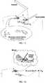
- the surgeonAfter accessing the anatomical cavity, the surgeon starts by rigidly attaching a marker to the bone surface that is referred as the World Marker (WM). If the marker is planar, then its projection is described by an homography H C , that maps plane points into image points, and encodes the relative rotation R C and translation t C between marker and camera reference frames. Thus, and since H C can be estimated from image information, it is possible to use this homography relation to determine at every frame time instant the 4x4 matrix C that transforms world coordinates into camera coordinates ( FIG 1A ).
- CR C t C 0 1
- the tool or instrumentis a calibrated touch-probe such that P T is the vector of 3D coordinates of its tip in the TM reference frame.
- the surgeoncan reconstruct a point of interest in the bone surface by touching it with the probe and acquiring a frame where both WM and TM are visible. This enables computation of the pose T of the probe and the obtaining of the point of interest P expressed in world coordinates ( FIG. 1C ).
- P 1T P T 1
- the process abovecan be applied to successive frames in order to reconstruct a curve in the bone surface.
- the surgeonoutlines the contour of interest while keeping both WM and TM in the Field-of-View (FOV) of the free-moving camera. This enables the obtaining of successive P estimates that define the desired 3D curve. Since 3D reconstruction results are stored in World Marker coordinates, the action of outlining can be stopped and resumed at any time. If the process is interrupted for any reason, it suffices for the camera to see again the WM for all the 3D information to be restored without having to repeat the tedious touching process ( FIG. 1C ).
- the 3D reconstruction resultscan be used for the purpose of measuring, estimating shape, or overlying a pre-operative plan in the actual patient anatomy (3D registration).
- This pre-operative plancan be a set of rules using anatomical landmarks, a statistical 3D model of the anatomy of interest, or an actual 3D image of the organ (e.g. CT Scan) augmented with guidance information inserted by the surgeon (surgical plan).
- a suitable 3D registration algorithmis selected for estimating the rigid transformation M that maps points P M in the pre-operative image into corresponding points P in the intra-operative reconstruction obtained with VTIAC ( FIG. 1D ).
- Thisenables representing the information of the model, including guidance information, in the system of coordinates of the world marker or, in other words, to overlay the pre-operative plan with the patient's anatomy ( FIG. 1E ).
- the clinical executionmight require, in one embodiment, multiple different instruments - such as guides, drills, shavers, saws, burrs, etc. - that can either be used in sequence or simultaneously.
- Each one of these instrumentsis assumed to have a Tool Marker (TM) attached that defines a local system of coordinates where the instrument's relevant parts - such as tip, symmetry axis, or even complete CAD model - are represented.
- TMTool Marker
- the systemprocesses each frame with the objective of detecting, identifying, and estimating the 3D pose of every TM that is in the FOV of the camera.
- the WMis also visible in image, then it is possible to determine the pose of the camera C, locate the instruments in the world coordinate system, relate their poses T with the 3D information stored in the WM reference frame, and ultimately provide real-time assistance to the surgeon ( FIG. 1E ).
- the last stage of VTIACconsists of assisting the surgeon by performing continuous processing of the video for estimating in real-time the 3D pose of instruments with respect to patient anatomy and/or surgical plan represented in WM coordinates.
- the assistancecan take multiple forms depending on a specific task and a preferred user interface.
- Possibilitiesinclude overlaying guidance information in video using Augmented Reality (AR), using computer graphics to animate the motion of instruments in a Virtual Reality (VR) environment showing the patient's anatomy and/or surgical plan, or controlling the action of actuators in the case of procedures assisted by robotic systems such as the Mako® or the Navio® robots.
- the apparatusincludes:
- the calibrationincludes determining the vector of parameters k and ⁇ of the back-projection function f -1 (the inverse of the projection function f) where k comprises the so-called intrinsic parameters - focal length, principal point, aspect ratio, and skew - and ⁇ stands for the radial distortion parameters.
- xf ⁇ 1 u ; k , ⁇
- the cameracan either be pre-calibrated from factory, using any standard method in literature, or calibrated in the Operating Room (OR) just before starting the procedure. The latter is especially recommendable for the case of arthroscopic cameras, or any other camera with exchangeable optics.
- the calibration in the ORcan be quickly accomplished by acquiring one image of a known calibration pattern from an arbitrary viewpoint, as described in U.S. Patent Publication No. US20140285676 . If the camera parameters change during operation because the surgeon rotates the lens scope and/or varies the optical zoom, then the initial calibration may be updated at every frame time using the techniques described in U.S. Patent Publication No. US20140285676 and Patent Publication WO2014054985 .
- the camera calibrationmust also take into account the medium of operation that, in the case of arthroscopy, is a wet medium.
- the initial single image calibrationcan either be carried in wet medium, or performed in air followed by compensating for the difference in the refractive index of air and water-based medium.
- WMWorld Marker
- TMsTool Markers
- the surgeonstarts by fixing the World Marker (WM) to the bone surface.
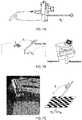
- the WMcan be any object comprising at least one planar facet with a known pattern that can be secured (e.g., glued), printed or engraved, and that can be recognized in images; that is small enough to be inserted into the anatomical cavity (e.g., up to 5mm diameter in the case of arthroscopy); and that can be mechanically attached to the surface such that bone and marker do not move with respect to each other.
- a non-exhaustive list of objects that can be used as WMincludes: a screw-like object with a flat head or facet ( FIG. 2B ); a nail-like object to be fixed by pressure with a flat head or facet; a needle like object with a flat lateral facet for trans-dermic insertion into the joint or cavity; or a flat button-like object that is pulled inside the joint or cavity by a thread or guide.
- the touch-probe in (iii) and the surgical tools in (iv)are instrumented with a visual marker (the Tool Marker or TM), which can either be originally built-in at manufacturing time, or rigidly attached by the user ( FIG. 2C, FIG. 2D ).
- TMTool Marker
- the tip of the tool, the orientation of the tool, or a complete CAD model of the toolmay be registered in the TM coordinate frame ( FIG. 2C ).
- This registration process as described hereinis referred to as tool calibration that can either be carried in factory for built-in markers, or performed by the user in case the markers are attached to the tool before starting the procedure.
- the operationcan be quickly carried simultaneously with the initial calibration of the camera without requiring the acquisition of additional calibration frames.
- the camera calibrationcan be accomplished by acquiring a single image of a known grid or checkerboard pattern. This enables recovering the intrinsic parameters k, the radial distortion parameters ⁇ , and the rigid transformation ⁇ that maps coordinates in the grid reference frame into coordinates in the camera reference frame.
- the tool calibration of the surgical instrumentscan either consist in determining the location of a point, a line or axis, or a CAD model in the coordinate system of the TM attached to the particular instrument. This can be accomplished with the help of the calibrated camera and touch-probe using a method similar to the one used for 3D reconstruction on the bone surface, but where the role of the WM is replaced by the TM of the instrument ( FIG. 1C ). Thus, for the case of a single point it is enough to pin-point it with the probe while keeping both the TM and the marker of the probe in the camera FOV. For the case of a line or axis the procedure is performed at least two times to reconstruct two points in TM coordinates lying on the line or axis. Finally, if the objective is to register a CAD model of the tool, then the procedure may be performed at least three times to obtain three landmark points in TM coordinates to be used as input in a standard registration method.
- the visual marker used in the WM of (ii) and in the TMs of (iii) and (iv)can comprise a single plane facet with a known pattern as assumed so far, or multiple plane facets with each facet having its own pattern that can be secured (e.g., glued), printed, or engraved, and where the location of each planar pattern is known in a common local coordinate system of the visual marker.
- the advantage of having multiple planar patterns facing different directionsis to extend the range of viewing positions and orientations from which the marker can be observed by the camera for estimating the relative 3D pose ( FIG. 1A, FIG. 1B ).
- the planar patternscan even be spread across different locations in the tool surface, in which case it suffices for the camera to see one of those patterns to successfully compute the relative pose T ⁇ .
- the visual markercan be non-planar, in which case it should comprise n ⁇ 3 points with known coordinates in the local reference frame of the marker, with these points being such that they can be detected and identified in image in order to allow estimation of the relative pose by applying a Perspective-n-Point (PnP) method.
- PnPPerspective-n-Point
- the small visual markers that are attached to instruments, tools, and anatomy of interestplay a fundamental role in VTIAC being key-enablers for using the camera as a measuring device for determining 3D pose.
- the visual markercan have different topological configurations but, for the sake of simplicity and without compromising generality, it will be assumed that the visual marker is a planar surface with a known pattern.
- This planar patternshould be such that it has a local system of coordinates, it is amenable to be detected and uniquely identified from its image projection, and it has fiducial points that can be accurately detected in image for estimating the plane-to-image homography H from point correspondences.
- a point correspondenceis the association between a point in the pattern p expressed in local coordinates and its projection x represented in camera coordinates.
- the homography His a projective transformation that maps the former into the latter, and that can be linearly estimated from N ⁇ 4 point correspondences.
- the homographyencodes the rotation and translation between pattern and camera coordinate systems, which means that the factorization of H provides the 3D pose of the pattern in the camera reference frame.
- planar patternsare similar to the CalTag checkerboard patterns, where the quadrilateral shape and high contrast enable fast detection, the sharp corners provide accurate point correspondences, and a bitmap binary code allows visual identification ( FIG. 3A ).
- These patternsare broadly used as fiducial markers for applications in augmented reality, for which there are several image processing pipelines such as the ARToolKit or the ALVAR. These pipelines implement the steps of detection, identification, and homography estimation in a computationally efficient manner to provide the 3D pose of each planar pattern at every frame time instant.
- this disclosureprovides an alternative approach based in photo-geometry.
- the approachincludes using standard methods for detection, identification, and initial estimation of pattern rotation r 0 and translation t 0 , followed by refining the 3D pose estimate by minimizing the photo-geometric error in aligning the current pattern image with its template using a warping function that takes into account the nonlinear distortion.
- C 0be the initial 3D pose estimate of the planar pattern in camera coordinates.
- the objectiveis to determine the pose update ⁇ , that encodes the increments in rotation ⁇ R and in translation ⁇ t , such that the photo-geometric error ⁇ i , is minimized ( FIG. 3C, FIG. 3D ) where T(u) is the pattern template, I(u) is the current frame, N i is the image region comprising the pattern, and w is the image warping function ( FIG.
- the iterative minimization of the photo-geometric error ⁇ ican be carried using different optimization schemes available in literature such as forward composition, inverse composition, or efficient second order minimization, which requires some changes in formulation and parametrization in SE(3).
- the formulationcan also be extended to be resilient to changes in illumination.
- Section 4describes a method, which per se does not constitute an embodiment of the invention, for estimating the 3D pose of a planar visual marker in camera coordinates. Let's consider two of these markers such that one is attached to the anatomy of interest (WM), and the other is attached to a calibrated touch probe (TM).
- WManatomy of interest
- TMcalibrated touch probe
- surgeonplaces the tip of the probe in the point, positions the camera such that both WM and TM are in the FOV, and commands the system to acquire an image that is processed as follows ( FIG. 4A ):
- the approachcan be extended to obtain a 3D contour or a sparse 3D reconstruction of a surface region, in which case the surgeon uses the touch probe to respectively outline the contour or randomly grasp the surface, while the camera acquires continuous video and steps above are executed for each frame ( FIG. 4B , FIG. 4C ).
- the 3D reconstruction resultsare stored in memory in world coordinates, which means that they can be overlaid in images whenever the WM is in the camera FOV by performing the following steps at each frame time instant ( FIG. 4A, FIG. 4B , FIG. 4C ):
- VTIACability of VTIAC to reconstruct and store in memory points, curves, and regions in the anatomy of interest (e.g. bone) has a multitude of purposes and/or possible clinical applications.
- a non-exhaustive listincludes:
- the reconstruction resultscan also be used as input in standard 3D registration methods for aligning or overlying a computational model with the current patient's anatomy.
- Such methodsestimate the rigid transformation M that maps points P M in the model into corresponding points P in the intra-operative reconstruction obtained with VTIAC ( FIG. 1D ).
- the term 'surgical plan'is employed in a broad sense and can mean, among other things, a set of rules based on anatomical landmarks, e.g. placing the femoral tunnel of the ACL at 1/3 the length of the notch ceiling measured from its posterior end; the fitting of a statistical model of an anatomy or pathology, e.g. the shape model of CAM femuro-acetabular impingement; or a pre-operative image of the targeted anatomy that can, or cannot, be augmented with guidance information, e.g. a CT scan annotated by the surgeon using a 3D planning software.
- This sectiondescribes how VTIAC can combine this 3D data with real-time 3D pose estimation of surgical instruments to provide intra-operative navigation features.
- the surgical instrument -that can be a needle, guide, drill, shaver, saw, burr, or any other object required for proper clinical execution - have a TM attached.
- the markerdefines a local reference frame where the position of a point, axis, or CAD model of the tool is known (calibrated tool). Navigation is accomplished by executing the following processing steps at every frame time instant:
- VTIAC navigationalso works for the case of multiple instruments being used in simultaneous, in which case each instrument has its own TM enabling parallel detection, identification, and estimation of 3D pose T.
- the aiding featurescan take multiple forms depending on the particular task and/or surgical procedure.
- a non-exhaustive list of these featuresincludes:
- the disclosurehas considered that camera and tool or instrument are two entities with independent motions. There are situations for which it might be advantageous to assemble the camera in the tool or instrument such that the two entities become a single rigid body.
- the assemblythat is henceforth referred as a Camera Tool or CamT, must be calibrated such that the position of the tool tip, axis of interest, or CAD model of the tool or instrument, is known in the reference frame of the camera.
- the cameracan be mounted in a multitude of possible tools ranging from a touch-probe to an impactor for cup placement during hip arthroplasty, passing by burrs and drills. In this setup where camera and tools are physically attached, their relative 3D pose is known, and as long as the camera sees the WM, it is possible to determine the 3D pose of the tool in the global system of coordinates of WM.
- FIG. 7Ashows a prototype embodiment of a Camera Tool (CamT) including a small-camera mounted on a custom made hand-holder that can either be used as a free-hand camera similar ( FIG. 2A ), or coupled with touch-probe such that camera, holder, and probe become a single rigid body ( FIG. 7A ).
- the CamTis assumed to be calibrated meaning that the camera is calibrated and the 3D coordinates P C of the tip of the probe are known in the camera reference frame ( FIG. 7B ).
- the surgeonuses the CamT to touch the point of interest while the WM is kept in the FOV of the camera ( FIG. 7B ).
- the CamT described abovecan either be pre-calibrated from factory, or calibrated in the OR from a single image of a known grid or checkerboard pattern.
- the surgeonacquires the calibration frame by positioning the camera such that the pattern is visible in image and the tool tip touches a particular point P G whose coordinates are known in the coordinate system of the grid ( FIG. 7C ).
- the imageis used as input in the method that provides the camera intrinsic parameters k, the lens distortion ⁇ , and the rigid transformation ⁇ that maps coordinates in the grid reference frame into coordinates in the camera reference frame.
- Section 5discloses a method, which per se does not constitute an embodiment of the invention, for 3D reconstruction where the surgeon uses a calibrated touch-probe to pinpoint points of interest while the camera observes both the WM and the TM of the tool.
- This alternative probehenceforth referred as contactless probe, consists in a laser pointer that emits a collimated beam of visible light.
- the pointerhas a visual marker attached - the Tool Marker or TM - and it is assumed to be calibrated such that the position of the line L T defined by the beam is known in TM coordinates.
- the surgeondirects the laser pointer such that the beam becomes incident on the point of interest, and uses the camera to acquire an image where WM, TM, and point of light incidence are visible.
- the pointis reconstructed in 3D by intersecting the line L T of the beam with the back-projection line B x of the image point x where the point of light incidence is projected ( FIG. 7D ).
- the imageis processed as stated in Section 5 with the difference that step (iii) is replaced by the two following steps:
- Contactless 3D reconstructioncan also be accomplished using an Active Contactless Probe consisting in a Laser Rangefinder (LRF), or other equivalent device or technology relying on Time-of-Flight (ToF) principles, that is able to measure distances ⁇ along the direction of the beam line L T .
- LRFLaser Rangefinder
- ToFTime-of-Flight
- the LRFhas a visual marker attached and it is assumed to be calibrated such that the origin and unit direction of measurement, that are respectively S T and d T , are known in the local reference frame of TM.
- the surgeonorients the LRF such that the beam becomes incident with the point of interest in the anatomy, and acquires in a synchronous manner the distance measurement ⁇ and an image where both WM and TM are visible.
- the point of interestcan be outside the camera FOV ( FIG. 7E ).
- the World Marker or WMworks as a global reference, which means that it must be viewed by the camera whenever the surgeon wants to use VTIAC for reconstruction or guidance purposes. There might be situations for which keeping the WM in the camera FOV can be difficult to accomplish in practice, either because the camera has a limited FOV, or because the region to cover is simply too broad or wide.
- This problemis solved by using multiple markers as shown in FIG. 7F .
- the surgeoncan fix an auxiliary visual marker (WM') on a convenient location on the surface of the anatomy, and move the camera such that both WM and WM' lie in the FOV.
- W'enables to map information from WM into WM' and vice-versa, it suffices for the camera to see one of the markers for the reconstruction and guidance functionalities of VTIAC to be readily available.
- the region of operationcan be further extended by placing additional markers and repeating the step above to register them in world coordinates.
- Section 6discloses a method, which per se does not constitute an embodiment of the invention, for using VTIAC to assist the execution of a clinical procedure where the guidance information is provided by either overlying info in the images or video (AR), or by animating a VR model of anatomy and tools.
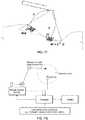
- VTIACcan also be used to guide or control the action of a surgical robot ( FIG 7G ).
- a surgical system like the Navio® robotrelies on conventional OT for determining in real-time the 3D pose between the robotized tool and patient's anatomy and/or surgical plan.
- VTIACcan be used as an alternative to conventional OT for providing the kinematic feedback required to control the robot in closed loop ( FIG 7G ).
- the robot end-effectorwhich is the tool or device at the end of the robotic arm or chain, must be instrumented with a Tool Marker and its tip, axis, or CAD model must be registered in TM coordinates.
- the relative 3D pose between end-effector and patient's anatomy/surgical planis determined as described in section 6 using video acquired by a camera that simultaneously sees the WM and TM.
- This sectiondiscloses an embodiment, not forming part of the invention per se, of VTIAC based-navigation for Reconstruction of Anterior Cruciate Ligament (ACL) in the Knee, which can also be generalized for other arthroscopic procedures such as in the shoulder or hip.
- ACLAnterior Cruciate Ligament
- ACL tearis a common pathology for which arthroscopy is the standard treatment (e.g., > 300000 cases per year worldwide).
- the procedureincludes replacing the torn ACL by a substitution graft that is pulled into the joint through a tunnel opened with a drill. Placing this tunnel in the correct anatomical position is crucial for the knee to fully recover its functionality.
- One techniqueis the transtibial (TT) approach that opens the tunnel in a single step by drilling from the bottom of the tibia plate till entering into the femur notch. Recent studies show that in about 39% of the cases TT fails in positioning the tunnel at the femoral end, and that much better results can be accomplished using the anteromedial (AM) approach.
- TTtranstibial
- AManteromedial
- VTIACmay be applied to accomplish this intra-operative navigation by indicating the location in the femur notch where to open the tunnel (the ligament footprint) and by guiding the angular orientation of drilling.
- the surgeonstarts by calibrating the arthroscopic camera and by attaching the WM in the medial side of the inter-condyle region ( FIG 5A ).
- the WMcan take the form of a button-like flat surface in the end of a wire guide that is pushed inside-out to go across the femur bone till it surfaces the patient skin. He/she then pulls the wire from the exterior for the marker to be pulled inside the joint and placed against the wall of the femur notch.
- the ligament footprintshould be located in the ceiling of the inter-condyle region at 1/3 the length of notch ceiling measured from its posterior end.
- the surgeonuses the touch-probe with the TM to pin-point the two ends of the notch ceiling such that VTIAC can measure the distance and compute the location of the footprint that is overlaid in the video using AR ( FIG 5A ).
- the orientation for opening the tunnelmay be determined by registering a statistical model of the femur bone.
- the surgeonuses the touch probe to reconstruct the boundary contours of the inter-condyle region ( FIG. 4B ) or, in alternative, to obtain a sparse 3D reconstruction of the surface of the femur bone ( FIG. 4C ).
- This 3D datais fed into a suitable 3D registration algorithm that overlays the statistical model with the patient's anatomy.
- the surgeonuses a drill with a TM such that its position can be related in real time with the 3D data stored in memory that includes reconstruction results and the registered statistical model.
- VTIACindicates the location of the footprint by overlaying in video using AR the point in the anatomy where drill tip should be place (the entry point)
- VTIACshows in a VR environment the registered model and the current orientation of the drilling tool, where this orientation is computed in real-time from the arthroscopic video where both WM and TM can be seen
- the VR environmentshows the drilling direction at each frame time instant such that the surgeon can align it for the exit point to be in the Lateral epicondyle ( FIG. 5B )
- the tunnelis open along the selected trajectory while VTIAC provides the depth from surface at each frame time instant.
- This sectiondiscloses an embodiment, not forming part of the invention per se, of VTIAC based-navigation for Placing Pedicle Screws (PPS) during spine surgery, which can also be generalized to other open procedures where a rigid surface is exposed, such as total hip replacement, total knee replacement, open shoulder surgery and implant placement in dentistry.
- PPSPedicle Screws
- VTIACalways requires a video input, its use is not limited to arthroscopy.
- the frameworkcan also be applied to open orthopedic procedures, such as knee/hip arthroplasty or spine surgery, as far as a camera is employed to observe incision and relevant anatomy.
- the cameracan either be a generic handheld camera ( FIG. 2A ) or a camera mounted on a tool, such as a touch-probe like in the CamT described in section 7 ( FIG. 7A ).
- PPSPedicle Screws
- the surgeonuses a pre-operative model of the vertebra (e.g. CT-Scan or MRI) to specify the 3D line along which the screw must be inserted, as well as the depth of insertion.
- the model and the surgeon specificationsare henceforth referred as the pre-operative 3D plan.
- This sectiondescribes how VTIAC can be applied to accomplish intra-operative navigation after planning.
- a visual markerplays the role of World Marker (WM) and is placed in an arbitrary position decided by the surgeon.
- the next stepis to overlay the pre-operative plan with patient's anatomy in the OR, which passes by reconstructing points and/or curves on the vertebra surface to be used as input in a suitable 3D registration algorithm.
- One possibilityis to perform the 3D registration using a set of fiducial points or landmarks in the anatomy.
- the systemindicates a succession of landmark points to be reconstructed that are pin-pointed in by the surgeon using the touch-probe ( FIG. 6A ).
- Another possibilityis to use specific contours in the anatomy or a sparse 3D reconstruction of the surface in which case the surgeon randomly grasps the vertebra with the probe ( FIG. 6B ).
- the reconstructioncan either be performed with the CamT, in which case the WM must be in the FOV of the camera ( FIG. 6A ), or with the standard touch probe with a TM attached, in which case both WM and TM must be visible in images ( FIG. 6B ).
- the VTIACis able to overlay the 3D pre-operative plan in the intra-operative video, as well as the tip, axis, or CAD model of the tool, whenever WM and TM are respectively in the FOV of the camera ( FIG. 6C ).
- the systemis able to animate the motion of the tool with respect to the pre-operative model in a VR environment ( FIG. 6D ).
- the VTIACcan then project the guidance information into the AR view, such as the angle of the tool relatively to the planned direction ( FIG. 6C ), or to provide a virtual extension of the tool for the surgeon to visualize the expected outcome of the chosen drill location and angle ( FIG 6D ).
- a strategy that is particularly effective and avoids errors whenever the insertion point on the bone surface is occluded by tissueis as follows: (i) configure the VR such that the optical axis of the virtual camera is aligned with the planned line S of insertion, (ii) move the tool tip along the occluding tissue till the tip overlays with line S that shows as a point, (iii) without moving the tip orient the tool such that its axis L shows as a point coincident with S and finally (iv) insert the tool till desired depth that is indicated by the system.
- VTIACcan be applied for intra-operative navigation in several other clinical procedures.
- a non-exhaustive list of possibilitiesinclude:
- PCLPosterior Cruciate Ligament
- FAIFemuro-Acetabular Impingement
- VTIACcan be applied to enforce the pre-planning by overlying the annotated 3D model with the patient's femur in order to safely guide the surgeon.
- the CAM footprintcan be overlaid in the arthroscopic video using AR techniques and the system can inform the surgeon about the quantity of the bone tissue to remove at every instant.
- confocal defectsare damages in the articular cartilage that can be repaired by filling the holes or craters with a biocompatible material. This operation often requires placing in the hole or crater an rigid support structure called scaffolder. VTIAC can be used for measuring and determining the shape of confocal defects, as well as to guide the placement of these scaffolds.
- THRTotal hip replacement
- the implantconsists in a cup, that replaces acetabulum in the pelvic bone, and in a stem with a sphere that replaces the femural head.
- VTIACcan be applied to guide the placement of the cup such that it is inserted with optimal angular orientation, as well as to define the cut plane in the femural neck to remove the head and insert the stem with sphere.
- Knee arthroplastyis an open surgical procedure for replacing total or part of the knee joint by an implant (total or unicompartmental knee replacement).
- VTIACcan be applied to guide the surgeon in cutting the femural condyle and placing the implant.
- Shoulder Joint ReplacementThis is another open surgical procedure for replacing in total or in part the shoulder joint by an implant.
- VTIACcan be applied in assisting the surgeon in several steps of the execution such as indicating the plane of cut to remove humeral head, or guiding the reaming of humeral shaft and/or glenoid.
- VTIACcan be applied in dental surgery for placing an implant in the maxilar bone as planned in a pre-operative Cone Beam CT (CBCT) of the patient.
- CBCTCone Beam CT
- the WMis rigidly attached to a tooth
- the CBCTis overlaid with patient's anatomy by using VTIAC features for 3D reconstruction, and the system provides intra-operative guidance for inserting the implant through any of the AR and VR features that have been described in the ACL and PPS examples.
- FIG. 8is a schematic diagram of an embodiment of an image processing system 500 that may correspond to or may be part of a computer and/or any other computing device, such as a handheld computer, a tablet computer, a laptop computer, a portable device, a workstation, a server, a mainframe, a super computer, and/or a database.
- the image processing system 500includes a processor 502, which may also be referenced as a central processor unit (CPU).
- the processor 502may communicate (e.g., via a system bus) and/or provide instructions to other components within the image processing system 500, such as the input interface 504, output interface 506, and/or memory 508.
- the processor 502may include one or more multi-core processors and/or memory (e.g., cache memory) that function as buffers and/or storage for data.
- processor 502may be part of one or more other processing components, such as application specific integrated circuits (ASICs), field-programmable gate arrays (FPGAs), and/or digital signal processors (DSPs).
- ASICsapplication specific integrated circuits
- FPGAsfield-programmable gate arrays
- DSPsdigital signal processors
- FIG. 8illustrates that processor 502 may be a single processor, processor 502 is not so limited and instead may represent a plurality of processors.
- the processor 502may be configured to implement any of the methods described herein.
- FIG. 8illustrates that memory 508 may be operatively coupled to processor 502.
- Memory 508may be a non-transitory computer readable medium configured to store various types of data.
- memory 508may include one or more memory devices that comprise secondary storage, read-only memory (ROM), and/or random-access memory (RAM).
- the secondary storageis typically comprised of one or more disk drives, optical drives, solid-state drives (SSDs), and/or tape drives and is used for non-volatile storage of data.
- the secondary storagemay be used to store overflow data if the allocated RAM is not large enough to hold the working data.
- the secondary storagemay also be used to store programs that are loaded into the RAM when such programs are selected for execution.
- the ROMis used to store instructions and perhaps data that are read during program execution.
- the ROMis a non-volatile memory device that typically has a small memory capacity relative to the larger memory capacity of the secondary storage.
- the RAMis used to store volatile data and perhaps to store computer executable instructions.
- the memory 508may be used to house the instructions described herein.
- the memory 508may comprise an image processing module 510 that may be accessed and implemented by processor 502.
- the image processing module 510may be stored and accessed within memory embedded in processor 502 (e.g., cache memory).
- the image processing module 510may estimate the camera response function and the vignetting in case of non-uniform illumination using one or more calibration images.
- memory 508interfaces with a computer bus so as to communicate and/or transmit information stored in memory 508 to processor 502 during execution of software programs, such as an operating system, application programs, device drivers, and software modules that comprise program code, and/or computer executable process steps, incorporating functionality described herein, e.g., the image processing module 510.
- Processor 502first loads computer executable process steps from storage, e.g., memory 510, storage medium /media, removable media drive, and/or other storage device.
- Processor 502can then execute the stored process steps in order to execute the loaded computer executable process steps.
- Stored datae.g., data stored by a storage device, can be accessed by processor 502 during the execution of computer executable process steps to instruct one or more components within the image processing system 500.
- Programming and/or loading executable instructions onto memory 508 and processor 502 in order to transform the image processing system 500 into a non-generic particular machine or apparatus that applies VTIAC to surgical proceduresis well-known in the art.
- Implementing instructions, real-time monitoring, and other functions by loading executable software into a computer and/or processorcan be converted to a hardware implementation by well-known design rules and/or transform a general-purpose processor to a processor programmed for a specific application. For example, decisions between implementing a concept in software versus hardware may depend on a number of design choices that include stability of the design and numbers of units to be produced and issues involved in translating from the software domain to the hardware domain.
- a designmay be developed and tested in a software form and subsequently transformed, by well-known design rules, to an equivalent hardware implementation in an ASIC or application specific hardware that hardwires the instructions of the software.
- a machine controlled by a new ASICis a particular machine or apparatus, likewise a computer that has been programmed and/or loaded with executable instructions may be viewed as a non-generic particular machine or apparatus.
- FIG. 8illustrates that the processor 502 may be operatively coupled to an input interface 504 configured to obtain one or more images and output interface 506 configured to output and/or display the images.
- the input interface 504may be configured to obtain one or more images via electrical, optical, and/or wireless connections using one or more communication protocols.
- the input interface 502may be a network interface that comprises a plurality of ports configured to receive and/or transmit data via a network.
- the networkmay transmit image data via wired links, wireless link, and/or logical links.
- the input interface 504may include but are not limited to a keyboard, universal serial bus (USB) interfaces, CD-ROMs, DVD-ROMs and/or graphical input devices (e.g., onscreen and/or virtual keyboards).
- the output interface 506may be an interface used to display information in a readable format for a user and/or used to transmit information to a separate apparatus or machine. Examples include, but are not limited to, a graphic display (e.g., monitors and display screens), a user interface, an interface used to connect to a printing device configured to produce hard-copies of the generated results, and output ports used to connect to a network and/or another computing device.
- Image processing system 500may also include computing components not explicitly shown in FIG. 8 , but well-known in the art, such as one or more power supplies, network interface(s), audio interfaces, displays, and circuitry used to connect the processor 502, input interfaces 504, output interface 506, and memory 508.
- internal architecture 900 of a computing device(s), computing system, computing platform and the likeincludes one or more processing units, processors, or processing cores, (also referred to herein as CPUs) 912, which interface with at least one computer bus 902.
- processing unitsprocessors, or processing cores, (also referred to herein as CPUs) 912, which interface with at least one computer bus 902.
- Computer-readable medium, or media906, network interface 914, memory 904, e.g., random access memory (RAM), run-time transient memory, read only memory (ROM), media disk drive interface 920 as an interface for a drive that can read and/or write to media including removable media such as floppy, CD-ROM, DVD, media, display interface 910 as interface for a monitor or other display device, keyboard interface 916 as interface for a keyboard, pointing device interface 918 as an interface for a mouse or other pointing device, and miscellaneous other interfaces 922 not shown individually, such as parallel and serial port interfaces and a universal serial bus (USB) interface.
- RAMrandom access memory
- ROMread only memory
- media disk drive interface 920as an interface for a drive that can read and/or write to media including removable media such as floppy, CD-ROM, DVD, media
- display interface 910as interface for a monitor or other display device
- keyboard interface 916as interface for a keyboard
- pointing device interface 918as an interface for
- Memory 904interfaces with computer bus 902 so as to provide information stored in memory 904 to CPU 912 during execution of software programs such as an operating system, application programs, device drivers, and software modules that comprise program code, and/or computer executable process steps, incorporating functionality described herein, e.g., one or more of process flows described herein.
- CPU 912first loads computer executable process steps from storage, e.g., memory 904, computer readable storage medium/media 906, removable media drive, and/or other storage device.
- CPU 912can then execute the stored process steps in order to execute the loaded computer-executable process steps.
- Stored datae.g., data stored by a storage device, can be accessed by CPU 912 during the execution of computer-executable process steps.
- Persistent storagee.g., medium/media 906, can be used to store an operating system and one or more application programs. Persistent storage can also be used to store device drivers, such as one or more of a digital camera driver, monitor driver, printer driver, scanner driver, or other device drivers, web pages, content files, playlists and other files. Persistent storage can further include program modules and data files used to implement one or more embodiments of the present disclosure.
- a network linktypically provides information communication using transmission media through one or more networks to other devices that use or process the information.
- the network linkmay provide a connection through a local network to a host computer or to equipment operated by a Network or Internet Service Provider (ISP).
- ISP equipmentin turn provides data communication services through the public, worldwide packet-switching communication network of networks now commonly referred to as the Internet.
- a computer called a server host connected to the Internethosts a process that provides a service in response to information received over the Internet.
- server hosthosts a process that provides information representing video data for presentation at display 910. It is contemplated that the components of system 900 can be deployed in various configurations within other computer systems, e.g., host and server.
- At least some embodiments of the present disclosureare related to the use of computer system 900 for implementing some or all of the techniques described herein. According to one embodiment, those techniques are performed by computer system 900 in response to processing unit 912 executing one or more sequences of one or more processor instructions contained in memory 904. Such instructions, also called computer instructions, software and program code, may be read into memory 904 from another computer-readable medium 906 such as storage device or network link. Execution of the sequences of instructions contained in memory 904 causes processing unit 912 to perform one or more of the method steps described herein. In alternative embodiments, hardware, such as ASIC, may be used in place of or in combination with software. Thus, embodiments of the present disclosure are not limited to any specific combination of hardware and software, unless otherwise explicitly stated herein.
- the signals transmitted over network link and other networks through communications interfacecarry information to and from computer system 900.
- Computer system 900can send and receive information, including program code, through the networks, among others, through network link and communications interface.
- a server hosttransmits program code for a particular application, requested by a message sent from computer, through Internet, ISP equipment, local network and communications interface.
- the received codemay be executed by processor 902 as it is received, or may be stored in memory 904 or in storage device or other non-volatile storage for later execution, or both.
- a moduleis a software, hardware, or firmware (or combinations thereof) system, process or functionality, or component thereof, that performs or facilitates the processes, features, and/or functions described herein (with or without human interaction or augmentation).
- a modulecan include sub-modules.
- a module, or software components of a modulemay be stored on a computer readable medium for execution by a processor. Modules may be integral to one or more servers, or be loaded and executed by one or more servers. One or more modules may be grouped into an engine or an application.
Landscapes
- Engineering & Computer Science (AREA)
- Health & Medical Sciences (AREA)
- Medical Informatics (AREA)
- Surgery (AREA)
- Public Health (AREA)
- Life Sciences & Earth Sciences (AREA)
- General Health & Medical Sciences (AREA)
- Nuclear Medicine, Radiotherapy & Molecular Imaging (AREA)
- Theoretical Computer Science (AREA)
- Biomedical Technology (AREA)
- Physics & Mathematics (AREA)
- General Physics & Mathematics (AREA)
- Heart & Thoracic Surgery (AREA)
- Molecular Biology (AREA)
- Animal Behavior & Ethology (AREA)
- Veterinary Medicine (AREA)
- Epidemiology (AREA)
- Primary Health Care (AREA)
- Robotics (AREA)
- General Engineering & Computer Science (AREA)
- Computer Vision & Pattern Recognition (AREA)
- Multimedia (AREA)
- Signal Processing (AREA)
- Pathology (AREA)
- Human Computer Interaction (AREA)
- Radiology & Medical Imaging (AREA)
- Databases & Information Systems (AREA)
- Data Mining & Analysis (AREA)
- Urology & Nephrology (AREA)
- Computer Graphics (AREA)
- Computer Hardware Design (AREA)
- Software Systems (AREA)
- Oral & Maxillofacial Surgery (AREA)
- Geometry (AREA)
- Physical Education & Sports Medicine (AREA)
- Biophysics (AREA)
- Endoscopes (AREA)
- Image Processing (AREA)
- Length Measuring Devices By Optical Means (AREA)
Description
- The disclosure generally relates to the field of computer-aided surgery, and in particular, but not by way of limitation, the disclosed embodiments refer to computer aided-navigation in camera guided procedures of surgery and diagnosis in anatomical regions with rigid tissues such as bone, which includes arthroscopy of knee, hip, or shoulder, and open surgery in orthopedics and dentistry in which case a camera must be used to observe the operating field. One or more embodiments can also be employed in any other application domain, such as industrial inspection, that uses a camera system to visualize a work space that comprises rigid, non-deformable parts.
- Minimally Invasive Surgical (MIS) procedures aim to minimize damage to healthy tissue by accessing targeted organs and anatomical cavities through relatively small size incisions. Since the workspace is not fully exposed, the surgeon typically carries the medical procedure using as guidance video acquired by a camera system that is inserted into the cavity. MIS procedures are being increasingly adopted in different medical specialties, such as orthopedics, abdominal surgery, urology, neurosurgery, and ENT, just to name a few.
- Arthroscopy is a MIS procedure for treatment of damaged joints in which instruments and endoscopic camera (the arthroscope) are inserted into the articular cavity through small incisions (the surgical ports). Arthroscopy, as opposed to conventional open surgery, largely preserves the integrity of the articulation, which is beneficial for the patient in terms of reduction of trauma, risk of infection and recovery time. Unfortunately, arthroscopic procedures are relatively difficult to execute because of indirect visualization and limited maneuverability inside the joint, with novices having to undergo a long training period and experts often making mistakes of clinical consequences. This is a scenario where computer-assistive technologies for safely guiding the surgeon throughout the procedure can make a difference, both in terms of improving clinical outcome and in terms of decreasing the surgeon learning curve.
- Depending on the particular clinical application, a system for Computer-Aided Surgery (CAS) comprises two distinct stages: (i) an offline step in which the procedure is planned leading to some sort of computational model that can either be a three-dimensional (3D) pre-operative image of the patient's organ (e.g. CT-Scan), a statistical bone model, or a set of guidelines for inferring meaningful locations with respect to anatomical landmarks; and (ii) an intra-operative navigation step in which the computer guides the surgeon throughout the procedure for the execution to be done as defined.
- The intra-operative navigation usually passes by overlying the pre-operative computational model with the actual bone, and by localizing in real-time the tools and instruments with respect to each other, and with respect to the targeted organ. Typically, the technology to accomplish this task is Optical-Tracking (OT) that consists in using a stationary stereo head, henceforth called base station, for tracking a set of markers that are rigidly attached to instruments and/or bone. The stereo head comprises two infrared (IR) cameras that track a set of point markers that are rigidly attached to the object of interest. The position of each marker is estimated by simple triangulation and, since their relative arrangement is known 'a priori', the 3D pose of the object of interest is computed in the reference frame of the base station. Recently, a technological variant of OT was introduced in which the two IR cameras are replaced by two conventional video cameras operating in the visible spectrum, and the arrangements of IR markers are replaced by planar markers with printed known patterns.
- The surgical navigation solutions that are currently available for Orthopedics, Neurosurgery, and ENT invariably rely in OT. In generic terms, the typical workflow passes by the surgeon to rigidly attach a tool marker to patient and/or targeted organ, which is followed by pin pointing anatomical landmarks with a calibrated tracked probe. The 3D position of these landmarks is determined in the coordinate system of the base station and the pre-operative computational model is registered with the patient. From this point on, it is possible to determine in real-time the pose of instruments with respect to patient and plan, which enables the system to safely guide the surgeon throughout the procedure. There are some variants to this scheme that mainly address the difficulties in performing the 3D registration of patient's anatomy with a pre-operative model with a tracked probe that tends to be an error prone, time consuming process. For example, the O-arm from Medtronic® combines OT with a CT-scanner that enables the acquiring of the 3D pre-operative model of patient's anatomy in the Operating Room (OR) before starting the procedure, which avoids the surgeon performing explicit registration. The system that is being developed by 7D Surgical® goes in the same direction with the 3D model being obtained using multi-view reconstruction and structured light to avoid the ionizing radiation of CT-scanning. Nevertheless, these systems still rely in conventional OT to know the relative position between instruments and anatomy after registration has been accomplished.
- OT has proved to be an effective way of obtaining real-
time 3D information in the OR, which largely explains the fact of being transversally used across different systems and solutions. However, the technology has several drawbacks that preclude a broader dissemination of surgical navigation: (i) it requires a significant investment in capital equipment, namely in acquiring the base station; (ii) it disrupts normal surgical workflow by changing the OR layout to accommodate additional equipment, by forcing the surgeon to work with instruments with bulky tool markers attached, and by constraining the team movements due to the need of preserving lines of sight between base station and tool markers; and (iii) it is not well suited to be used in MIS procedures because organs and tissues are occluded which avoids placing marker tools that can be observed from the outside by the base station. For example, OT based navigation in arthroscopic procedures always requires opening additional incisions such that the marker tool attached to the bone protrudes through patient skin. - In recent years some alternative technologies have emerged in an attempt of obviating the above-mentioned drawbacks. Electromagnetic Tracking (ET) is currently used in some surgical navigation systems with the advantage of not requiring preservation of a line of sight. However, it has the problem of being vulnerable to electromagnetic interference caused by nearby metals and devices, being in practice less reliable and accurate than OT. Moreover, it still requires additional capital equipment, namely a base station, and the need of attaching coil markers with hanging wires to organs makes it non amenable to MIS procedures.
- Patent application
EP 2153794 discloses a navigation system which includes a display monitor, a CPU, and a camera, wherein the camera is mounted to a back side of the display monitor to form a monitor unit, in which the reference units are placed on a body while acquiring an image data set, and are tracked during a surgical operation by the monitor unit to register and correlate a position of a visual image of an exterior surface of the body. - Patent application
WO2009042644 discloses a method provided for assisting cartilage diagnostic and therapeutic procedures which includes acquiring 3D osteocartilaginous parameters by using multimodal 3D tracked device for building a bone tracking virtual real-time environment. - Patent applications
WO2014122301 ,US2011130761 ,WO2013052187 disclose other similar solutions, however of even less relevance with regard to the present invention. - The embodiments in the disclosure provide a new concept for computer-assisted procedures of surgery and diagnosis that target rigid, non-deformable anatomical parts such as bone, tissue, or teeth. The disclosure describes attaching small visual markers to instruments and anatomy of interest (e.g. bone surface), with each marker having a printed known pattern for detection and unique identification in images acquired by a free-moving camera, and a geometry that enables estimating its rotation and translation with respect to the camera using solely image processing techniques.
- The concept, henceforth referred as Visual-Tracking Inside the Anatomical Cavity (VTIAC), introduces three main differences from other embodiments of OT/ET in the context of computer-aided surgery: First, the global world reference frame, instead of being the coordinate frame of the external base station, it is the system of coordinates of a marker that is rigidly attached to the anatomy of interest (e.g. bone surface). This marker, referred to herein as World Marker or WM, serves as absolute reference such that all measurements are expressed in its coordinates (world coordinates); Second, the free-moving camera acts as the single sensing modality with all measurements and real-
time 3D inferences being carried by processing the acquired video. This feature avoids significant investments in additional capital equipment when compared with OT/ET; and Third, since measurements are performed in high resolution images acquired at close range, the metric accuracy of VTIAC is significantly better than the one accomplished with OT/ET. - The disclosure discloses the apparatus for VTIAC and the required initial calibration procedures, it describes how to use VTIAC to perform very accurate 3D measurements inside the anatomical cavity, and it shows how to use augmented reality, virtual reality, or robotics to provide real-time guidance to the surgeon after registering a pre-operative 3D plan.
- In terms of clinical applications VTIAC is specially well suited for arthroscopy where the already existing monocular arthroscope acts as the free-moving camera that provides the video input. VTIAC can be successfully employed in any clinical procedure that targets anatomical regions with rigid parts, such as open orthopaedic surgery or dentistry, in which case the operating field must be observed by a camera that can either be attached to a tool or handheld. The disclosure describes illustrative implementations in knee arthroscopy and spine surgery that by no means limit the range of possible clinical applications.
- For a more complete understanding of the present disclosure, reference is made to the following detailed description of exemplary embodiments considered in conjunction with the accompanying drawings.
FIG. 1A is an embodiment of a representation of the computation of the World Marker (WM) 3D pose C in the camera reference frame using the homography relation HC that maps WM points into image points.FIG. 1B is an embodiment of a representation of a tool with a Tool Marker (TM) and WM being simultaneously seen by the camera. Both the rigid transform between the WM and the camera (C), and between the TM and the camera (T̂) can be computed using the homography relations. The rigid transform between WM and TM (T) can be easily computed from the previous transforms.FIG. 1C is an embodiment of a representation of the 3D reconstruction of points, curves, or sparse mesh in the surface of the rigid tissue using a touch-probe with a TM that is calibrated such that the tipPT is known. By keeping the WM and TM in the FOV of the camera, pointsP in the bone surface can be referenced in the WM reference frame by mappingPT using the transformation T that is determined from visual information.FIG. 1D is an embodiment of a representation of the operation of overlying a surgical plan with the patient's anatomy by using the 3D reconstruction results in a suitable 3D registration algorithm that provides the rigid transformation M that maps surgical plan coordinates into WM coordinates.FIG. 1E is an embodiment of a representation of VTIAC assisted execution of a surgical procedure where the surgical plan is overlaid into images in real-time (Augmented Reality) for the purpose of guiding the surgeon in positioning and/or orienting an instrument.FIG. 2A is an example of some of the free moving cameras that can be used with the VTIAC. Top is an endoscopic lens than can be attached to a camera-head for visualization during arthroscopy, and bottom is a generic handheld camera that can be employed for VTIAC intra-operative navigation in open surgery with direct visual access.FIG. 2B is an embodiment of a World Marker (WM) that is in this particular case a screw-like object that comprises one planar facet with a known visual pattern that defines the world system of coordinates.FIG. 2C is an embodiment of a touch-probe with a Tool Marker (TM) attached that defines a local system of coordinates in which the position of the tipPT is known.FIG. 2D is an embodiment of a surgical instrument with a Tool Marker (TM) attached to the surgical instruments for execution of the clinical procedure. The surgical tool can be any tool used during the operation, including but not limited to powered tools (e.g. resection bur), drill guides, or any other instrument used for resection or palpation. The TM defines a local system of coordinates in which the position of instrument's relevant parts - such as tip, symmetry axis, or even a complete CAD model of the instrument - are known.FIG. 2E is a schematic of an embodiment of the image processing system, that may correspond to or may be part of a computer and/or any other computing device, that receives as input images and video acquired by the camera, as well as commands that may be entered by a button panel, keyboard, camera buttons, foot switch and/or any other input interface, and that outputs the processing results to a display.FIG. 2F is an embodiment of a representation of the tool calibration process, which includes finding the coordinatesPT of a particular tool point in the TM reference frame. The calibration operation can be quickly carried in simultaneous with the initial calibration of the camera without requiring the acquisition of additional calibration frames. The rigid transformation Ĝ maps coordinates in the grid reference frame into coordinates in the camera reference frame. When the tool tip is placed in a pre-defined pointPG that is known in grid coordinates, and the calibration image is such that TM is visible, then it is possible to estimate the 3D pose T̂ of the tool marker from image information and obtain the TM coordinates of the tool tip.FIG. 3A is an embodiment of a planar pattern template (synthetic image), where the quadrilateral shape and high contrast enable fast detection of the corners, the sharp corners provide accurate point detection (P1,P2,P3 andP4), and a bitmap binary code allows visual identification.FIG. 3B is an embodiment of the result of detection and identification of a planar marker in close-range operation using a wide FOV camera that introduces very strong radial distortion. The correct detection and point correspondences (u1,u2,u3 andu4 againstP1, P2,P3 andP4 of the template pattern) is not accurate enough for the demands of the medical applications, due to the compression effect of the radial distortion in the periphery of the image.FIG. 3C is an embodiment of the representation of the camera pose estimation using the detection on the highly distorted image (C0) and the camera pose estimation(C) after computing the pose update Δ. This pose update is computed by minimizing the photo-geometric error between the template pattern and the detection on the image.FIG. 3D is an embodiment of a representation of the warping operation for the minimization of the photo-geometric error between the template pattern and the current marker detection in the image. The pose update Δ encodes the increments in rotationδR and in translationδt, that are estimated taking into account the amount of distortion in the image for increased accuracy.FIG. 4A is an embodiment of the VTIAC reconstructing points in 3D in ACL reconstruction. The tip of the probe is positioned such that both WM and TM are in the FOV of the camera. Points position in 3D are memorized by the system in the reference frame of the WM. The figure shows the Augmented Reality (AR) view, where information is overlaid, and in the top right corner the Virtual Reality (VR) view where points are displayed in 3D.FIG. 4B is an embodiment of the VTIAC reconstructing curves in 3D in ACL reconstruction where the surgeon uses the touch-probe to outline the curves. These particular curves are the inter-condyle contours that are overlaid in image and shown in 3D in the VR window in the top right corner of image.FIG. 4C is an embodiment of the VTIAC reconstructing a dense surface by randomly grasping the bone surface with an instrumented tool. On the upper right corner, the reconstructed points in 3D are shown, along with a graphical representation of the touch probe.FIG. 4D is an embodiment of using the VTIAC to measure distance between points. By pinpointing points with a calibrated tool, TM coordinates are transferred to the WM reference frame, and distances are computed with sub-millimetric accuracy.FIG. 4E is an embodiment of using the VTIAC to measure shape and/or area of a region by establishing a closed contour on the bone surface. This shape can then be analyzed to infer metrics such as area of tissue to remove or volume of implants needed for surgery.FIG. 5A is an embodiment of using the VTIAC to find the location of the femoral tunnel in ACL reconstruction. This is accomplished by measuring the length of the notch ceiling and placing the ACL footprint at 1/3 the length counting from the posterior end.FIG. 5B is an embodiment of using the VTIAC to correctly orient the drill tool for opening the femoral tunnel in ACL reconstruction. This is accomplished by using the VR view to anticipate in real-time the position and exit point of the tunnel depending on the pose of the drill tool that is determined at each frame instant from arthroscopic video.FIG. 6A is an embodiment of using the VTIAC to pinpoint points for the purpose of registration with a pre-operative model of the patient's anatomy in Placing Pedicle Screws (PPS) in spine surgery. On the top, fiducial points on the vertebra are indicated to the surgeon (green point in the upper right corner VR view) so he/she can touch the correspondent point in the patient's anatomy. The point correspondences are then used for 3D registration. In this case the touch-probe is rigidly attached to the camera (CamT) which means that only the WM is required to be visible in imagesFIG. 6B is an embodiment or using VTIAC to reconstruct a sparse mesh on the surface of the vertebra for the purpose of registration with a pre-operative model during PPS. In this case the touch-probe is independent of the camera and both WM and TM must be kept in the image.FIG. 6C is an embodiment of using the VTIAC for the measurement of the angle of the insertion in PPS in spine surgery. Virtual representation of the insertion guide is presented in the upper right corner (VR view) and the angle measurement between instrumented Kirschner wire and guide is presented in the AR view. In this case the VTIAC system can provide visual alerts when the angle of penetration is considered acceptable.FIG. 6D is an embodiment of using the VTIAC for the visual inspection of the perforation trajectory for PPS. The virtual representation of the instrument is augmented along its axis so the surgeon can see the outcome of the perforation for each position of the tool.FIG. 6E is an embodiment of using the VTIAC for guiding a perforation or insertion of instrument during PPS. In VR view, the optical axis of the virtual camera is aligned with the desired line of perforation or insertion. The penetration depth displayed is relative to the bone surface at the entry point.FIG. 7A is a prototype of the embodiment of a Camera Tool (CamT) including a small-camera mounted on a custom made hand-holder that can either be used as a free-hand camera, or coupled with touch-probe such that camera, holder, and probe become a single rigid body.PC is the tool tip that can be calibrated with respect to the camera.FIG. 7B is an embodiment of using the CamT to reconstruct points in the bone surface. The 3D coordinatesPC of the tip of the probe are known in the camera reference frame and therefore they can be referenced to the WM for measurements computation, as if it was a tool with a TM.FIG. 7C is an embodiment of a representation of the CamT calibration using a single image of the calibration pattern to simultaneously calibrate the camera and the tool tip positionPG. When the tool is touching the calibration pattern at a point of known coordinatesPG, the transformPC between the tool point of contact withPG and the camera reference frame is given byPC =G.PG.FIG. 7D is an embodiment of a representation of using the VTIAC with a laser pointer instead of a touch probe for contactless measurements. The lases pointer is instrumented with a TM that is in the FOV of the camera. The laser pointer produces a colored dot on the bone/tissue surface (point of incidence), that is seen in the image (as well as the TM and WM). The point is reconstructed in 3D by intersecting the lineLT of the beam with the back-projection lineBx of the image pointx where the point of light incidence is projected.FIG. 7E is an embodiment of a representation of using the VTIAC with a Laser Rangefinder (LRF), or other equivalent device or technology relying in Time-of-Flight (ToF) principles, that is able to measure distances along the direction of the beam lineLT. The origin and unit direction of measurement,ST anddT, are known in the local reference frame of TM. For 3D reconstruction the surgeon orients the LRF such that the beam becomes incident with the point of interest in the anatomy, and acquires in a synchronous manner the distance measurement λ and an image where both WM and TM are visible. The point of interest can be outside the camera FOV.FIG. 7F is an embodiment of a representation of the use of multiple WM to increase the area of operation. The surgeon can fix an auxiliary visual marker (WM') on a convenient location on the bone surface, and move the camera such that both WM and WM' lie in the FOV. This enables registration of the auxiliary marker in the WM reference frame by making W' = C-1 C' with C and C' being the poses of WM and WM' in camera coordinates. From this point on it is sufficient for the camera to see one of the markers in order to be registered in the global reference frame.FIG. 7G is an embodiment of a representation of using the VTIAC to provide control commands to a robotic system. The robotic end effector is instrumented with a TM and the anatomy has a WM attached such that relative 3D pose can be computed from video acquired by the free-moving camera. The VTIAC uses the visual feedback to guide the positioning of the end-effector by sending commands to the robot. The robotic arm can also provide feedback of the actuators state that can be fused with visual feedback for more accurate closed loop control.FIG. 8 is a schematic diagram of an embodiment of an image processing system.FIG. 9 is a schematic diagram of an embodiment of a computing device.- It should be understood that, although an illustrative implementation of one or more embodiments are provided below, the various specific embodiments may be implemented using any number of techniques known by persons of ordinary skill in the art. The disclosure should in no way be limited to the illustrative embodiments, drawings, and/or techniques illustrated below, including the exemplary designs and implementations illustrated and described herein.
- One or more embodiments disclosed herein applies to camera-guided orthopedic MIS procedures, namely arthroscopy, that is used as illustrative example throughout most of the description. However, the application of the presently disclosed embodiments can include other surgical procedures and clinical specialties where the operating field comprises rigid, non-deformable parts and surfaces. The application of the disclosed embodiments requires a camera system for visualizing the anatomical scene that might already exist (e.g. arthroscopy) or be added (e.g. open orthopedic surgery).
- One or more embodiments in the disclosure provide a surgical navigation scheme for arthroscopy and other procedures using a conventional camera and with scenes that comprise rigid surfaces. The surgical navigation scheme will be referred to as Visual-Tracking Inside the Anatomical Cavity (VTIAC). The disclosure relates to attaching small, recognizable visual markers to instruments and rigid anatomy (e.g. bones) and use the free-moving camera, that is the arthroscope in case of arthroscopic procedures, to estimate their relative rotation and translation (the relative 3D pose). For the case of the markers being planar with a printed known pattern, the relative 3D pose is determined by estimating the plane-to-image homography that is factorized to obtain the rotation and translation between plane and camera reference frames. The marker attached to the bone surface, referred to herein as World Marker (WM), serves as absolute reference with all measurements being expressed in its coordinate system (world coordinates). VTIAC can be used to obtain 3D information about the bone surface, register a pre-operative computational model, and ultimately solve the navigation issues by providing guidance using augmented reality, virtual reality, or robotic actuation.
- VTIAC introduces many differences relatively to other embodiments of OT/ET in the context of computer-aided surgery in general and arthroscopy in particular. For example, the global world reference frame, instead of being the external stereo head (the base station), is substituted by the system of coordinates of the WM that is inside the articular cavity. This avoids issues related to preserving lines of sight in the OR, as well as the need of having marker tools protruding through patient skin. Second, for example, the approach relies on processing the video acquired by a free-moving camera, which means that in the case of arthroscopy there is no need of investing in additional capital equipment that provides alternative sensing modalities. Third, for example, measurements are performed in the images acquired at close range inside the anatomical cavity, which dramatically increases spatial and/or metric accuracy with respect to OT or ET.
- In embodiments where the visual marker is a planar marker, the plane-to-image homography may be a factor in the VTIAC approach for surgical navigation. The projection of a plane into a perspective image may be described by a 3x3 matrix transformation (the homography) that encodes the plane rotation and translation (the
plane 3D pose) in camera coordinates. The homography has been broadly used in the field of Computer Vision for several different purposes, ranging from camera calibration to visual tracking, and passing by 3D motion estimation. - The use of plane homographies in clinical setups has been relatively scarce. For example, an OT system, the MicronTracker® developed by Claronav®, may use planes with recognizable patterns as tool markers. These markers are tracked by a stereo camera system and the pose of the tool is determined through homography factorization. The approach herein described differs from MicronTracker® in that the tracking is performed by a moving monocular camera as opposed to a stationary stereo setup. Moreover, while in MicronTracker® the base station is the external stereo setup, which raises the issues about line of sight inherent to conventional OT, in VTIAC, measurements are carried out with respect to the WM that is rigidly attached to the surface inside the articular joint or anatomical cavity.
- Other embodiments may be used to determine the relative pose between a laparoscope and an intra-operative ultrasound (US) probe or laser projector. In particular, the embodiments attach a printed planar pattern to the probe and/or projector that is viewed by the laparoscope. This enables estimation of the plane-to-image homography and determination of the relative pose of the probe and/or projector in camera coordinates. VTIAC provides a much broader range of functionalities that arise from using a World Marker (WM) attached to the bone surface. Thus, VTIAC not only provides the relative pose of tools and devices that are inserted into the anatomical cavity, but it also enables the reconstruction of points and contours on the surface of the organ of interest that are pin-pointed by the surgeon. This information can be used for a multitude of purposes such as metric measurements, registration of pre-operative models, or guidance using augmented reality, that are seamlessly supported by the framework. Moreover, measurements are typically represented in camera coordinates, which means that it is not possible to relate or integrate information across frames because the laparoscope is in constant motion. In VTIAC, all measurements are stored in the coordinate system of the WM that works as an absolute reference across time and space. Thus, the visual tracking process can even be discontinued, and the 3D information obtained till that moment becomes readily available as soon as the WM is redetected in the images acquired by the moving camera.
- Section 2 provides an overview of the concepts behind the VTIAC,
Section 3 provides details on the apparatus and calibration of the necessary tools to be used with the system, Section 4 provides a description of the visual markers' accurate detection under high radial distortion, Section 5 details the estimation of 3D pose from the detection of markers in the image and practical capabilities of the system, Section 6 provides an overview of the operation flow of the VTIAC system for operation during surgery and Section 7 provides extensions and variations on the tools and methods presented before. - In order to better illustrate the usefulness of VTIAC, two embodiments that can be applied to design a navigation system for the arthroscopic reconstruction of the Anterior Cruciate Ligament (ACL) and for Placing Pedicle Screws (PPS) in spine surgery are presented (sections 8 and 9). These procedures are mere examples that do not limit in any way the potential applications of VTIAC. As stated in the following sections, the VTIAC can be applied to a multitude of arthroscopic procedures, as well as open procedures and including dentistry surgery.
- Notation: If not stated otherwise, points are represented by their vectors of coordinates and vectors are denoted by a bold letter (e.g.,P, x). The rigid displacement between coordinate frames is represented by a 4x4 matrix in the Special Euclidean Group (SE(3)) where the left upper 3x3 submatrix is a rotation matrix and 3x1 right upper submatrix is a translation vector. Matrices are typically denoted by plain capital letters (e.g., C, T).
- The free-moving camera is assumed to be calibrated such that image pointsu in pixel coordinates can be mapped into image pointsx in metric coordinates as if the image had been acquired by a perfect pin-hole. For the sake of simplicity, and without lack of generality, it is considered that the free-moving camera is an arthroscopic camera and that the anatomical part of interest is a bone. It is also assumed that visual markers are planar with a known pattern.
- After accessing the anatomical cavity, the surgeon starts by rigidly attaching a marker to the bone surface that is referred as the World Marker (WM). If the marker is planar, then its projection is described by an homography HC, that maps plane points into image points, and encodes the relative rotation RC and translationtC between marker and camera reference frames. Thus, and since HC can be estimated from image information, it is possible to use this homography relation to determine at every frame time instant the 4x4 matrix C that transforms world coordinates into camera coordinates (
FIG 1A ).
- Consider now an instrument or tool with a similar visual marker attached that is referred as Tool Marker (TM). Repeating the process of the previous paragraph the homography HT can be estimated from image information in order to determine the rigid transformation that maps TM coordinates into camera coordinates. If both WM and TM are simultaneously visible in the image, then it is possible to estimate the 3D poses of world and tool markers in the camera frame and find in a straightforward manner the location T of the tool or instrument in the world coordinate system (
FIG. 1B )
- Let's now assume that the tool or instrument is a calibrated touch-probe such thatPT is the vector of 3D coordinates of its tip in the TM reference frame. The surgeon can reconstruct a point of interest in the bone surface by touching it with the probe and acquiring a frame where both WM and TM are visible. This enables computation of the pose T of the probe and the obtaining of the point of interestP expressed in world coordinates (
FIG. 1C ).
- The process above can be applied to successive frames in order to reconstruct a curve in the bone surface. The surgeon outlines the contour of interest while keeping both WM and TM in the Field-of-View (FOV) of the free-moving camera. This enables the obtaining of successiveP estimates that define the desired 3D curve. Since 3D reconstruction results are stored in World Marker coordinates, the action of outlining can be stopped and resumed at any time. If the process is interrupted for any reason, it suffices for the camera to see again the WM for all the 3D information to be restored without having to repeat the tedious touching process (
FIG. 1C ). - The 3D reconstruction results, that can either be points, contours, or sparse surface meshes, can be used for the purpose of measuring, estimating shape, or overlying a pre-operative plan in the actual patient anatomy (3D registration). This pre-operative plan can be a set of rules using anatomical landmarks, a statistical 3D model of the anatomy of interest, or an actual 3D image of the organ (e.g. CT Scan) augmented with guidance information inserted by the surgeon (surgical plan). Let's assume the latter for illustrative purposes (
FIG. 1D ). In this case a suitable 3D registration algorithm is selected for estimating the rigid transformation M that maps pointsPM in the pre-operative image into corresponding pointsP in the intra-operative reconstruction obtained with VTIAC (FIG. 1D ). This enables representing the information of the model, including guidance information, in the system of coordinates of the world marker or, in other words, to overlay the pre-operative plan with the patient's anatomy (FIG. 1E ). - The clinical execution might require, in one embodiment, multiple different instruments - such as guides, drills, shavers, saws, burrs, etc. - that can either be used in sequence or simultaneously. Each one of these instruments is assumed to have a Tool Marker (TM) attached that defines a local system of coordinates where the instrument's relevant parts - such as tip, symmetry axis, or even complete CAD model - are represented. The system processes each frame with the objective of detecting, identifying, and estimating the 3D pose of every TM that is in the FOV of the camera. If the WM is also visible in image, then it is possible to determine the pose of the camera C, locate the instruments in the world coordinate system, relate their poses T with the 3D information stored in the WM reference frame, and ultimately provide real-time assistance to the surgeon (
FIG. 1E ). - Thus, the last stage of VTIAC consists of assisting the surgeon by performing continuous processing of the video for estimating in real-time the 3D pose of instruments with respect to patient anatomy and/or surgical plan represented in WM coordinates. The assistance can take multiple forms depending on a specific task and a preferred user interface. Possibilities include overlaying guidance information in video using Augmented Reality (AR), using computer graphics to animate the motion of instruments in a Virtual Reality (VR) environment showing the patient's anatomy and/or surgical plan, or controlling the action of actuators in the case of procedures assisted by robotic systems such as the Mako® or the Navio® robots.
- This section overviews the methods and apparatus that are required to perform computer-aided surgery using VTIAC. The apparatus includes:
- (i). A free-moving camera, that can either be an arthroscopic camera or a generic handheld camera, and that is calibrated at all times such that image points in pixel units can be back-projected into directions or image points expressed in the metric coordinate system of the camera (
FIG. 2A ); - (ii). A visual marker, henceforth referred as the World Marker or WM, consisting in an object that is meant to be rigidly attached to a surface, that comprises at least one planar facet with a known pattern that can be secured (e.g., glued), printed or engraved, and where this pattern defines the world system of coordinates (
FIG. 2B ); - (iii). A touch-probe that is a tool or instrument of any material comprising a handgrip and a tip, and that has at least one visual marker, henceforth referred as Tool Marker or TM, that consists in at least one planar facet with a known pattern that can be secured (e.g., glued), printed or engraved, and where the pattern defines a local system of coordinates in which the position of the tipPT is known (
FIG. 2C ); - (iv). The surgical instruments for proper execution of the clinical procedure, where each instrument has at least one visual marker, henceforth referred as Tool Marker or TM, that includes at least one planar facet with a known pattern that can be secured (e.g., glued), printed or engraved, and where the pattern defines a local system of coordinates in which the position of instrument's relevant parts - such as tip, symmetry axis, or even a complete CAD model of the instrument - are known (
FIG. 2D ); - (v). An image processing system, that may correspond to or may be part of a computer and/or any other computing device, that receives as input images and video acquired by the camera (i), as well as commands that may be entered by a button panel, keyboard, camera buttons, foot switch and/or any other input interface, and that outputs the processing results to a display and/or to a robotic actuator (
FIG. 2E ); - (vi). Placement of the WM in an arbitrary location in the surface of the rigid anatomical part of interest, with this placement being such that WM and part of interest do not move with respect to each other.
- (vii). 3D reconstruction of points and/or contours in the surface of the rigid anatomical part by using the touch-probe to pin-point those points and/or outline those contours while keeping both WM and TM of the probe in the Field-of-View (FOV) of the camera (
FIG. 1C ). - (viii). Application of 3D reconstruction results for the purpose of measuring, making inference, or overlaying a pre-operative surgical plan with the current patient's anatomy, in which case a suitable 3D registration method may be used for determining the rigid displacement between the coordinate system of the WM, that is attached to the anatomy of interest, and the reference frame of the surgical plan (
FIG. 1D ). - (ix). Assisted clinical execution using the surgical instruments of (iii) where the camera simultaneously observes the TMs and the WM for locating the instruments in world coordinates, and where real-time guidance is accomplished by relating these locations with 3D reconstructions results and/or overlaid surgical plan (
FIG. 1E ). - Since the VTIAC uses images for measurements and 3D inference, the free-moving camera must be calibrated at all times during the procedure such that 2D image pointsu, represented in pixel coordinates, can be mapped into 2D pointsx (or back-projection directions) represented in the metric system of coordinates of the camera. The calibration includes determining the vector of parametersk and ξ of the back-projection functionf-1 (the inverse of the projection functionf) wherek comprises the so-called intrinsic parameters - focal length, principal point, aspect ratio, and skew - and ξ stands for the radial distortion parameters.

- The camera can either be pre-calibrated from factory, using any standard method in literature, or calibrated in the Operating Room (OR) just before starting the procedure. The latter is especially recommendable for the case of arthroscopic cameras, or any other camera with exchangeable optics. The calibration in the OR can be quickly accomplished by acquiring one image of a known calibration pattern from an arbitrary viewpoint, as described in U.S. Patent Publication No.
US20140285676 . If the camera parameters change during operation because the surgeon rotates the lens scope and/or varies the optical zoom, then the initial calibration may be updated at every frame time using the techniques described in U.S. Patent Publication No.US20140285676 and Patent PublicationWO2014054985 . The camera calibration must also take into account the medium of operation that, in the case of arthroscopy, is a wet medium. In this situation the initial single image calibration can either be carried in wet medium, or performed in air followed by compensating for the difference in the refractive index of air and water-based medium. - The surgeon starts by fixing the World Marker (WM) to the bone surface. The WM can be any object comprising at least one planar facet with a known pattern that can be secured (e.g., glued), printed or engraved, and that can be recognized in images; that is small enough to be inserted into the anatomical cavity (e.g., up to 5mm diameter in the case of arthroscopy); and that can be mechanically attached to the surface such that bone and marker do not move with respect to each other.
- A non-exhaustive list of objects that can be used as WM includes: a screw-like object with a flat head or facet (
FIG. 2B ); a nail-like object to be fixed by pressure with a flat head or facet; a needle like object with a flat lateral facet for trans-dermic insertion into the joint or cavity; or a flat button-like object that is pulled inside the joint or cavity by a thread or guide. - The touch-probe in (iii) and the surgical tools in (iv) are instrumented with a visual marker (the Tool Marker or TM), which can either be originally built-in at manufacturing time, or rigidly attached by the user (
FIG. 2C, FIG. 2D ). Depending on the tool purpose, the tip of the tool, the orientation of the tool, or a complete CAD model of the tool may be registered in the TM coordinate frame (FIG. 2C ). This registration process as described herein is referred to as tool calibration that can either be carried in factory for built-in markers, or performed by the user in case the markers are attached to the tool before starting the procedure. - If the tool calibration includes finding the coordinatesPT of a particular tool point in the TM reference frame (e.g. the tip of the touch probe (iii)), then the operation can be quickly carried simultaneously with the initial calibration of the camera without requiring the acquisition of additional calibration frames. As described, e.g., in U.S. Patent Publication No.
US2014/0285676 , the camera calibration can be accomplished by acquiring a single image of a known grid or checkerboard pattern. This enables recovering the intrinsic parametersk, the radial distortion parameters ξ, and the rigid transformation Ĝ that maps coordinates in the grid reference frame into coordinates in the camera reference frame. Thus, if the tool tip is placed in a pre-defined pointPG that is known in grid coordinates, and the calibration image is such that TM is visible, then it is possible to estimate the 3D pose T̂ of the tool marker from image information and obtain the TM coordinates of the tool tip by applying the formula below (FIG. 2F ).
- The tool calibration of the surgical instruments (iv) can either consist in determining the location of a point, a line or axis, or a CAD model in the coordinate system of the TM attached to the particular instrument. This can be accomplished with the help of the calibrated camera and touch-probe using a method similar to the one used for 3D reconstruction on the bone surface, but where the role of the WM is replaced by the TM of the instrument (
FIG. 1C ). Thus, for the case of a single point it is enough to pin-point it with the probe while keeping both the TM and the marker of the probe in the camera FOV. For the case of a line or axis the procedure is performed at least two times to reconstruct two points in TM coordinates lying on the line or axis. Finally, if the objective is to register a CAD model of the tool, then the procedure may be performed at least three times to obtain three landmark points in TM coordinates to be used as input in a standard registration method. - The visual marker used in the WM of (ii) and in the TMs of (iii) and (iv) can comprise a single plane facet with a known pattern as assumed so far, or multiple plane facets with each facet having its own pattern that can be secured (e.g., glued), printed, or engraved, and where the location of each planar pattern is known in a common local coordinate system of the visual marker. The advantage of having multiple planar patterns facing different directions is to extend the range of viewing positions and orientations from which the marker can be observed by the camera for estimating the relative 3D pose (
FIG. 1A, FIG. 1B ). In the case of TMs, the planar patterns can even be spread across different locations in the tool surface, in which case it suffices for the camera to see one of those patterns to successfully compute the relative pose T̂. - Alternatively, the visual marker can be non-planar, in which case it should comprise n≥3 points with known coordinates in the local reference frame of the marker, with these points being such that they can be detected and identified in image in order to allow estimation of the relative pose by applying a Perspective-n-Point (PnP) method.
- The small visual markers that are attached to instruments, tools, and anatomy of interest play a fundamental role in VTIAC being key-enablers for using the camera as a measuring device for determining 3D pose. As discussed, the visual marker can have different topological configurations but, for the sake of simplicity and without compromising generality, it will be assumed that the visual marker is a planar surface with a known pattern.
- This planar pattern should be such that it has a local system of coordinates, it is amenable to be detected and uniquely identified from its image projection, and it has fiducial points that can be accurately detected in image for estimating the plane-to-image homography H from point correspondences. A point correspondence is the association between a point in the patternp expressed in local coordinates and its projectionx represented in camera coordinates. The homography H is a projective transformation that maps the former into the latter, and that can be linearly estimated from N ≥ 4 point correspondences. The homography encodes the rotation and translation between pattern and camera coordinate systems, which means that the factorization of H provides the 3D pose of the pattern in the camera reference frame.
- There are several pattern designs that meet the above mentioned conditions. It will be assumed, without compromising generality, that the planar patterns are similar to the CalTag checkerboard patterns, where the quadrilateral shape and high contrast enable fast detection, the sharp corners provide accurate point correspondences, and a bitmap binary code allows visual identification (
FIG. 3A ). These patterns are broadly used as fiducial markers for applications in augmented reality, for which there are several image processing pipelines such as the ARToolKit or the ALVAR. These pipelines implement the steps of detection, identification, and homography estimation in a computationally efficient manner to provide the 3D pose of each planar pattern at every frame time instant. Unfortunately, the application to computer-aided surgery is not straightforward because the close-range operation requires cameras with a wide FOV that typically introduce very strong radial distortion. The distortion hinders correct detection and point correspondences, which is not compatible with the high-accuracy demands of the medical applications (FIG. 3B ). - One possibility for improving accuracy and robustness of 3D pose estimation is to correct radial distortion via software, before running the processing pipeline for detection, identification, and homography/pose estimation. However, this has several drawbacks, such as the computational effort in warping the entire frame, and the fact that interpolation also introduces artifacts that degrade the accuracy of geometric estimation.
- Since radial distortion has a relatively small impact in pattern detection, this disclosure provides an alternative approach based in photo-geometry. The approach includes using standard methods for detection, identification, and initial estimation of pattern rotationr0 and translationt0, followed by refining the 3D pose estimate by minimizing the photo-geometric error in aligning the current pattern image with its template using a warping function that takes into account the nonlinear distortion.
- Let C0 be the initial 3D pose estimate of the planar pattern in camera coordinates. The objective is to determine the pose update Δ, that encodes the increments in rotationδR and in translationδt, such that the photo-geometric error εi, is minimized (
FIG. 3C, FIG. 3D )
FIG. 3D ) given by
withh being the homography map that depends on the relative 3D poser andt, andf denoting the projection function of the camera that encodes the effect of radial distortion, as described, e.g., in Patent PublicationWO/2014054958 . Since the template can be understood as a synthetic, fronto-parallel image of the planar pattern (FIG. 3D ), that has calibration parametersk' and ξ', the homographyh depends on the rigid displacement of the views. The final 3D pose estimate is given by:
- The iterative minimization of the photo-geometric error εi can be carried using different optimization schemes available in literature such as forward composition, inverse composition, or efficient second order minimization, which requires some changes in formulation and parametrization in SE(3). The formulation can also be extended to be resilient to changes in illumination.
- Section 4 describes a method, which per se does not constitute an embodiment of the invention, for estimating the 3D pose of a planar visual marker in camera coordinates. Let's consider two of these markers such that one is attached to the anatomy of interest (WM), and the other is attached to a calibrated touch probe (TM).
- For reconstructing an arbitrary pointP in world coordinates the surgeon places the tip of the probe in the point, positions the camera such that both WM and TM are in the FOV, and commands the system to acquire an image that is processed as follows (
FIG. 4A ): - (i). Detect, identify, and estimate the 3D pose C of the WM in camera coordinates using the method in section 4.
- (ii). Detect, identify, and estimate the 3D pose T̂ of the TM in camera coordinates using the method in section 4.
- (iii). Reconstruct pointP in world coordinates by applying the
formula 
- (iv). Store the reconstructed pointP in memory for future reference.
- The approach can be extended to obtain a 3D contour or a sparse 3D reconstruction of a surface region, in which case the surgeon uses the touch probe to respectively outline the contour or randomly grasp the surface, while the camera acquires continuous video and steps above are executed for each frame (
FIG. 4B ,FIG. 4C ). - The 3D reconstruction results are stored in memory in world coordinates, which means that they can be overlaid in images whenever the WM is in the camera FOV by performing the following steps at each frame time instant (
FIG. 4A, FIG. 4B ,FIG. 4C ): - Detect, identify, and estimate the 3D pose C of the WM in camera coordinates using the method in section 4.
Map 3D data from world coordinates into camera coordinates using C.- Project the 3D data into image using functionf with camera calibration parametersk, ξ.
- The ability of VTIAC to reconstruct and store in memory points, curves, and regions in the anatomy of interest (e.g. bone) has a multitude of purposes and/or possible clinical applications. A non-exhaustive list includes:
- measuring the distance between two points (
FIG. 4D ); - measuring thickness (e.g. of cartilage coating);
- measuring depth (e.g. of perforation or insertion);
- measuring volume of a protruding or sunken region (e.g. a confocal cartilage defect);
- finding shape and/or area of a region by determining its boundary contour (
FIG. 4E ); - fitting a parametric curve and/or shape;
- As stated, the reconstruction results can also be used as input in standard 3D registration methods for aligning or overlying a computational model with the current patient's anatomy. Such methods estimate the rigid transformation M that maps pointsPM in the model into corresponding pointsP in the intra-operative reconstruction obtained with VTIAC (
FIG. 1D ). - So far we have shown how to obtain relevant 3D data in the common coordinate system of the WM that may consist in reconstruction results, measurements and other types of 3D inferences, or the registration of surgical plan against patient's anatomy. The term 'surgical plan' is employed in a broad sense and can mean, among other things, a set of rules based on anatomical landmarks, e.g. placing the femoral tunnel of the ACL at 1/3 the length of the notch ceiling measured from its posterior end; the fitting of a statistical model of an anatomy or pathology, e.g. the shape model of CAM femuro-acetabular impingement; or a pre-operative image of the targeted anatomy that can, or cannot, be augmented with guidance information, e.g. a CT scan annotated by the surgeon using a 3D planning software. This section describes how VTIAC can combine this 3D data with real-
time 3D pose estimation of surgical instruments to provide intra-operative navigation features. - Let the surgical instrument - that can be a needle, guide, drill, shaver, saw, burr, or any other object required for proper clinical execution - have a TM attached. The marker defines a local reference frame where the position of a point, axis, or CAD model of the tool is known (calibrated tool). Navigation is accomplished by executing the following processing steps at every frame time instant:
- (i). Detect, identify, and estimate the 3D pose C of the WM in camera coordinates using the method in section 4.
- (ii). If the pose C has been successfully estimated proceed as follows:
- 1. Detect, identify, and estimate the 3D pose T̂ of the TM in camera coordinates using the method in section 4.
- 2. If pose T̂ of the surgical instrument is successfully estimated then
- ▪ Compute the 3D pose T of TM in WM coordinates using equation 2.
- ▪ Map the tool calibration information, that can be points, axes, or CAD models, into world coordinates using the rigid transformation T.
- ▪ Relate the tool calibration information with the 3D data stored in memory to make measurements and inferences for the purpose of real-time guidance (e.g. distances and angles between surgical instrument and guides in surgical plan)
- 3. Communicate guidance to the surgeon by either using Augmented Reality (AR), in which case info is overlaid in image using the camera pose C and projection functionf, or by animating a Virtual Reality (VR) 3D model.
- VTIAC navigation also works for the case of multiple instruments being used in simultaneous, in which case each instrument has its own TM enabling parallel detection, identification, and estimation of 3D pose T.
- The aiding features can take multiple forms depending on the particular task and/or surgical procedure. A non-exhaustive list of these features includes:
- Signaling target points in the anatomy for placement or insertion, e.g. indicating the ACL footprint where the femoral tunnel should be open (
FIG. 5A ); - Orienting a tool by providing the angle between its axis and the desired direction of insertion or placement, e.g. overlying the angle between current and desired orientation of a Kirschner wire (
FIG. 6C ); - Orienting a perforation instrument by anticipating the perforation trajectory, e.g. orienting the drill direction for Pedicle Screw Placement (
FIG. 6D ) or orienting the drill direction in ACL reconstruction such that tunnel joins the ACL footprint with the Lateral epicondyle (FIG. 5B ); - Guiding a perforation or insertion instrument by providing a view in VR where the optical axis of the virtual camera is aligned with the desired line of perforation or insertion, e.g. orienting the Kirschner wire during Pedicle Screw Placement (
FIG. 6E ). - Signaling a region or structure of tissue to be resected, as well as quantifying the amount of tissue to be resected, e.g. resection of cam (or pincer) femuroacetabular impingement (
FIG. 4E ) - Real-time measurement of distance or depth of insertion, e.g. insertion of Kirschner wire during Pedicle Screw Placement (
FIG. 6E ). - The disclosure has considered that camera and tool or instrument are two entities with independent motions. There are situations for which it might be advantageous to assemble the camera in the tool or instrument such that the two entities become a single rigid body. The assembly, that is henceforth referred as a Camera Tool or CamT, must be calibrated such that the position of the tool tip, axis of interest, or CAD model of the tool or instrument, is known in the reference frame of the camera. Depending on the particular clinical application the camera can be mounted in a multitude of possible tools ranging from a touch-probe to an impactor for cup placement during hip arthroplasty, passing by burrs and drills. In this setup where camera and tools are physically attached, their relative 3D pose is known, and as long as the camera sees the WM, it is possible to determine the 3D pose of the tool in the global system of coordinates of WM.
FIG. 7A shows a prototype embodiment of a Camera Tool (CamT) including a small-camera mounted on a custom made hand-holder that can either be used as a free-hand camera similar (FIG. 2A ), or coupled with touch-probe such that camera, holder, and probe become a single rigid body (FIG. 7A ). The CamT is assumed to be calibrated meaning that the camera is calibrated and the 3D coordinatesPC of the tip of the probe are known in the camera reference frame (FIG. 7B ). For 3D reconstruction the surgeon uses the CamT to touch the point of interest while the WM is kept in the FOV of the camera (FIG. 7B ). The acquired frame is processed as described insection 3 with the difference that step (ii) is skipped and the formula of step (iii) is replaced by
- The CamT described above can either be pre-calibrated from factory, or calibrated in the OR from a single image of a known grid or checkerboard pattern. In this case the surgeon acquires the calibration frame by positioning the camera such that the pattern is visible in image and the tool tip touches a particular pointPG whose coordinates are known in the coordinate system of the grid (
FIG. 7C ). The image is used as input in the method that provides the camera intrinsic parametersk, the lens distortion ξ, and the rigid transformation Ĝ that maps coordinates in the grid reference frame into coordinates in the camera reference frame. The tool calibration is fully accomplished by finding the camera coordinates of the tool tip that are given by
- Section 5 discloses a method, which per se does not constitute an embodiment of the invention, for 3D reconstruction where the surgeon uses a calibrated touch-probe to pinpoint points of interest while the camera observes both the WM and the TM of the tool. There might be situations for which touching a particular location in the anatomy is difficult or even unfeasible. Examples include situations of limited access or poor maneuverability where the touch-probe cannot reach a particular location without occluding the WM. It is now disclosed an alternative probe that can replace the conventional touch-probe in the task of performing 3D reconstruction using VTIAC, and that has the advantage of avoiding the need of physical contact.
- This alternative probe, henceforth referred as contactless probe, consists in a laser pointer that emits a collimated beam of visible light. The pointer has a visual marker attached - the Tool Marker or TM - and it is assumed to be calibrated such that the position of the lineLT defined by the beam is known in TM coordinates.
- For reconstruction the surgeon directs the laser pointer such that the beam becomes incident on the point of interest, and uses the camera to acquire an image where WM, TM, and point of light incidence are visible. The point is reconstructed in 3D by intersecting the lineLT of the beam with the back-projection lineBx of the image pointx where the point of light incidence is projected (
FIG. 7D ). Thus, the image is processed as stated in Section 5 with the difference that step (iii) is replaced by the two following steps: - 1. Detect the point of light incidencex in the image and determine the corresponding back-projection lineBx in camera coordinates.
- 2. Determine the 3D coordinatesPT of the point of light incidence in the TM reference frame by making:

- Contactless 3D reconstruction can also be accomplished using an Active Contactless Probe consisting in a Laser Rangefinder (LRF), or other equivalent device or technology relying on Time-of-Flight (ToF) principles, that is able to measure distances λ along the direction of the beam lineLT. The LRF has a visual marker attached and it is assumed to be calibrated such that the origin and unit direction of measurement, that are respectivelyST anddT, are known in the local reference frame of TM. For 3D reconstruction the surgeon orients the LRF such that the beam becomes incident with the point of interest in the anatomy, and acquires in a synchronous manner the distance measurement λ and an image where both WM and TM are visible. The point of interest can be outside the camera FOV (
FIG. 7E ). The reconstruction is accomplished using the processing steps of Section 5 with the pointPT of step (iii) being given by:
- The World Marker or WM works as a global reference, which means that it must be viewed by the camera whenever the surgeon wants to use VTIAC for reconstruction or guidance purposes. There might be situations for which keeping the WM in the camera FOV can be difficult to accomplish in practice, either because the camera has a limited FOV, or because the region to cover is simply too broad or wide. This problem is solved by using multiple markers as shown in
FIG. 7F . In order to increase the working region the surgeon can fix an auxiliary visual marker (WM') on a convenient location on the surface of the anatomy, and move the camera such that both WM and WM' lie in the FOV. A frame is acquired, the method of section 4 is applied to determine the 3D pose C and C' of the two markers (FIG. 7F ), and the rigid transformation W' that maps coordinates in the auxiliary marker into world coordinates is
- Since W' enables to map information from WM into WM' and vice-versa, it suffices for the camera to see one of the markers for the reconstruction and guidance functionalities of VTIAC to be readily available. The region of operation can be further extended by placing additional markers and repeating the step above to register them in world coordinates.
- Section 6 discloses a method, which per se does not constitute an embodiment of the invention, for using VTIAC to assist the execution of a clinical procedure where the guidance information is provided by either overlying info in the images or video (AR), or by animating a VR model of anatomy and tools. In addition, VTIAC can also be used to guide or control the action of a surgical robot (
FIG 7G ). - A surgical system like the Navio® robot relies on conventional OT for determining in real-time the 3D pose between the robotized tool and patient's anatomy and/or surgical plan. VTIAC can be used as an alternative to conventional OT for providing the kinematic feedback required to control the robot in closed loop (
FIG 7G ). In this case the robot end-effector, which is the tool or device at the end of the robotic arm or chain, must be instrumented with a Tool Marker and its tip, axis, or CAD model must be registered in TM coordinates. The relative 3D pose between end-effector and patient's anatomy/surgical plan is determined as described in section 6 using video acquired by a camera that simultaneously sees the WM and TM. - This section discloses an embodiment, not forming part of the invention per se, of VTIAC based-navigation for Reconstruction of Anterior Cruciate Ligament (ACL) in the Knee, which can also be generalized for other arthroscopic procedures such as in the shoulder or hip.
- ACL tear is a common pathology for which arthroscopy is the standard treatment (e.g., > 300000 cases per year worldwide). The procedure includes replacing the torn ACL by a substitution graft that is pulled into the joint through a tunnel opened with a drill. Placing this tunnel in the correct anatomical position is crucial for the knee to fully recover its functionality. One technique is the transtibial (TT) approach that opens the tunnel in a single step by drilling from the bottom of the tibia plate till entering into the femur notch. Recent studies show that in about 39% of the cases TT fails in positioning the tunnel at the femoral end, and that much better results can be accomplished using the anteromedial (AM) approach. Unfortunately, AM is used in about 15% of the cases because it is more difficult to execute and increases the risk of critically short tunnel or blowout of the posterior femur wall. Intra-operative navigation can help in disseminating the AM approach by dramatically decreasing the execution risk and complexity. VTIAC may be applied to accomplish this intra-operative navigation by indicating the location in the femur notch where to open the tunnel (the ligament footprint) and by guiding the angular orientation of drilling.
- In a possible design of the navigated procedure the surgeon starts by calibrating the arthroscopic camera and by attaching the WM in the medial side of the inter-condyle region (
FIG 5A ). The WM can take the form of a button-like flat surface in the end of a wire guide that is pushed inside-out to go across the femur bone till it surfaces the patient skin. He/she then pulls the wire from the exterior for the marker to be pulled inside the joint and placed against the wall of the femur notch. It is well known that the ligament footprint should be located in the ceiling of the inter-condyle region at 1/3 the length of notch ceiling measured from its posterior end. Thus, after placement of the WM, the surgeon uses the touch-probe with the TM to pin-point the two ends of the notch ceiling such that VTIAC can measure the distance and compute the location of the footprint that is overlaid in the video using AR (FIG 5A ). - The orientation for opening the tunnel may be determined by registering a statistical model of the femur bone. For this purpose, the surgeon uses the touch probe to reconstruct the boundary contours of the inter-condyle region (
FIG. 4B ) or, in alternative, to obtain a sparse 3D reconstruction of the surface of the femur bone (FIG. 4C ). This 3D data is fed into a suitable 3D registration algorithm that overlays the statistical model with the patient's anatomy. For opening the tunnel the surgeon uses a drill with a TM such that its position can be related in real time with the 3D data stored in memory that includes reconstruction results and the registered statistical model. One possible strategy for guided opening of the tunnel consists in the following: (i) VTIAC indicates the location of the footprint by overlaying in video using AR the point in the anatomy where drill tip should be place (the entry point), (ii) VTIAC shows in a VR environment the registered model and the current orientation of the drilling tool, where this orientation is computed in real-time from the arthroscopic video where both WM and TM can be seen, (iii) the VR environment shows the drilling direction at each frame time instant such that the surgeon can align it for the exit point to be in the Lateral epicondyle (FIG. 5B ), (iv) the tunnel is open along the selected trajectory while VTIAC provides the depth from surface at each frame time instant. - This section discloses an embodiment, not forming part of the invention per se, of VTIAC based-navigation for Placing Pedicle Screws (PPS) during spine surgery, which can also be generalized to other open procedures where a rigid surface is exposed, such as total hip replacement, total knee replacement, open shoulder surgery and implant placement in dentistry.
- Although VTIAC always requires a video input, its use is not limited to arthroscopy. The framework can also be applied to open orthopedic procedures, such as knee/hip arthroplasty or spine surgery, as far as a camera is employed to observe incision and relevant anatomy. The camera can either be a generic handheld camera (
FIG. 2A ) or a camera mounted on a tool, such as a touch-probe like in the CamT described in section 7 (FIG. 7A ). - There are several traumas and pathologies of the spine whose treatment passes by a surgery for vertebra fusion. The procedure includes placing screws in two consecutive vertebras for keeping in position a metallic rod that prevents intervertebral motion. Each screw must be carefully inserted along the vertebra pedicle otherwise it can irremediably damage the spinal medulla or a vital blood vessel. The dominant technique for Placing Pedicle Screws (PPS) is the so-called "free-hand" approach, in which the surgeon relies in his experience and knowledge to insert the screw while occasionally using fluoroscopy to confirm the correct positioning. Since this process is risky and error prone, several manufacturers developed navigation systems for PPS where a pre-operative 3D plan is overlaid with the patient anatomy in the OR using opto-tracking. In this case the surgeon uses a pre-operative model of the vertebra (e.g. CT-Scan or MRI) to specify the 3D line along which the screw must be inserted, as well as the depth of insertion. The model and the surgeon specifications are henceforth referred as the pre-operative 3D plan. This section describes how VTIAC can be applied to accomplish intra-operative navigation after planning.
- In the OR, and after opening an incision for partial or total exposition of the vertebra, the surgeon starts by rigidly attaching a visual marker (WM) to the bone surface. This marker plays the role of World Marker (WM) and is placed in an arbitrary position decided by the surgeon. The next step is to overlay the pre-operative plan with patient's anatomy in the OR, which passes by reconstructing points and/or curves on the vertebra surface to be used as input in a suitable 3D registration algorithm.
- One possibility is to perform the 3D registration using a set of fiducial points or landmarks in the anatomy. In this case the system indicates a succession of landmark points to be reconstructed that are pin-pointed in by the surgeon using the touch-probe (
FIG. 6A ). Another possibility is to use specific contours in the anatomy or a sparse 3D reconstruction of the surface in which case the surgeon randomly grasps the vertebra with the probe (FIG. 6B ). The reconstruction can either be performed with the CamT, in which case the WM must be in the FOV of the camera (FIG. 6A ), or with the standard touch probe with a TM attached, in which case both WM and TM must be visible in images (FIG. 6B ). - After registration, the VTIAC is able to overlay the 3D pre-operative plan in the intra-operative video, as well as the tip, axis, or CAD model of the tool, whenever WM and TM are respectively in the FOV of the camera (
FIG. 6C ). As an alternative, and since the position of the WM in the vertebra model becomes known, the system is able to animate the motion of the tool with respect to the pre-operative model in a VR environment (FIG. 6D ). - The VTIAC can then project the guidance information into the AR view, such as the angle of the tool relatively to the planned direction (
FIG. 6C ), or to provide a virtual extension of the tool for the surgeon to visualize the expected outcome of the chosen drill location and angle (FIG 6D ). A strategy that is particularly effective and avoids errors whenever the insertion point on the bone surface is occluded by tissue (FIG 6E ) is as follows: (i) configure the VR such that the optical axis of the virtual camera is aligned with the planned line S of insertion, (ii) move the tool tip along the occluding tissue till the tip overlays with line S that shows as a point, (iii) without moving the tip orient the tool such that its axis L shows as a point coincident with S and finally (iv) insert the tool till desired depth that is indicated by the system. - VTIAC can be applied for intra-operative navigation in several other clinical procedures. A non-exhaustive list of possibilities include:
- Arthroscopic reconstruction of Posterior Cruciate Ligament (PCL): The PCL is a ligament in the knee joint that connects the posterior intercondylar area of the tibia to the medial condyle of the femur. In a similar manner to the ACL, the PCL reconstruction consists in replacing the torn ligament by a substitution graft that is pulled inside the joint through a tunnel opened with a drill. VTIAC can be applied to guide the placement of these tunnels both in tibial and femoral sides.
- Arthroscopic Resection of Femuro-Acetabular Impingement (FAI): FAI occurs when the ball shaped femoral head rubs abnormally in the acetabular socket, which in about 91% of the cases is caused by an excess of bone tissue in the femur head-neck that creates a bump known as CAM impingement. The treatment is surgical and consists in removing the CAM to restore the ball shape to the femur-head. To accomplish this objective the surgeon uses a CT-scan of the femur to study the CAM position and plan the extension of resection. This plan is then mentally transposed for the execution in the OR, which is a very error prone process. VTIAC can be applied to enforce the pre-planning by overlying the annotated 3D model with the patient's femur in order to safely guide the surgeon. After model registration the CAM footprint can be overlaid in the arthroscopic video using AR techniques and the system can inform the surgeon about the quantity of the bone tissue to remove at every instant.
- Arthroscopic assessment and diagnosis of confocal defects in cartilage: Confocal defects are damages in the articular cartilage that can be repaired by filling the holes or craters with a biocompatible material. This operation often requires placing in the hole or crater an rigid support structure called scaffolder. VTIAC can be used for measuring and determining the shape of confocal defects, as well as to guide the placement of these scaffolds.
- Total hip replacement (THR): THR is an open surgical procedure for replacing the hip joint by an implant. The implant consists in a cup, that replaces acetabulum in the pelvic bone, and in a stem with a sphere that replaces the femural head. VTIAC can be applied to guide the placement of the cup such that it is inserted with optimal angular orientation, as well as to define the cut plane in the femural neck to remove the head and insert the stem with sphere.
- Total Knee Replacement and Unicompartmental Knee Replacement: Knee arthroplasty is an open surgical procedure for replacing total or part of the knee joint by an implant (total or unicompartmental knee replacement). VTIAC can be applied to guide the surgeon in cutting the femural condyle and placing the implant.
- Shoulder Joint Replacement: This is another open surgical procedure for replacing in total or in part the shoulder joint by an implant. VTIAC can be applied in assisting the surgeon in several steps of the execution such as indicating the plane of cut to remove humeral head, or guiding the reaming of humeral shaft and/or glenoid.
- Placement of dental implants in Prosthodontics: VTIAC can be applied in dental surgery for placing an implant in the maxilar bone as planned in a pre-operative Cone Beam CT (CBCT) of the patient. In this case the WM is rigidly attached to a tooth, the CBCT is overlaid with patient's anatomy by using VTIAC features for 3D reconstruction, and the system provides intra-operative guidance for inserting the implant through any of the AR and VR features that have been described in the ACL and PPS examples.
FIG. 8 is a schematic diagram of an embodiment of animage processing system 500 that may correspond to or may be part of a computer and/or any other computing device, such as a handheld computer, a tablet computer, a laptop computer, a portable device, a workstation, a server, a mainframe, a super computer, and/or a database. Theimage processing system 500 includes aprocessor 502, which may also be referenced as a central processor unit (CPU). Theprocessor 502 may communicate (e.g., via a system bus) and/or provide instructions to other components within theimage processing system 500, such as theinput interface 504,output interface 506, and/ormemory 508. In one embodiment, theprocessor 502 may include one or more multi-core processors and/or memory (e.g., cache memory) that function as buffers and/or storage for data. In other words,processor 502 may be part of one or more other processing components, such as application specific integrated circuits (ASICs), field-programmable gate arrays (FPGAs), and/or digital signal processors (DSPs). AlthoughFIG. 8 illustrates thatprocessor 502 may be a single processor,processor 502 is not so limited and instead may represent a plurality of processors. Theprocessor 502 may be configured to implement any of the methods described herein.FIG. 8 illustrates thatmemory 508 may be operatively coupled toprocessor 502.Memory 508 may be a non-transitory computer readable medium configured to store various types of data. For example,memory 508 may include one or more memory devices that comprise secondary storage, read-only memory (ROM), and/or random-access memory (RAM). The secondary storage is typically comprised of one or more disk drives, optical drives, solid-state drives (SSDs), and/or tape drives and is used for non-volatile storage of data. In certain instances, the secondary storage may be used to store overflow data if the allocated RAM is not large enough to hold the working data. The secondary storage may also be used to store programs that are loaded into the RAM when such programs are selected for execution. The ROM is used to store instructions and perhaps data that are read during program execution. The ROM is a non-volatile memory device that typically has a small memory capacity relative to the larger memory capacity of the secondary storage. The RAM is used to store volatile data and perhaps to store computer executable instructions.- As shown in
FIG. 8 , thememory 508 may be used to house the instructions described herein. In an embodiment, thememory 508 may comprise animage processing module 510 that may be accessed and implemented byprocessor 502. Alternatively, theimage processing module 510 may be stored and accessed within memory embedded in processor 502 (e.g., cache memory). Specifically, theimage processing module 510 may estimate the camera response function and the vignetting in case of non-uniform illumination using one or more calibration images. In one embodiment,memory 508 interfaces with a computer bus so as to communicate and/or transmit information stored inmemory 508 toprocessor 502 during execution of software programs, such as an operating system, application programs, device drivers, and software modules that comprise program code, and/or computer executable process steps, incorporating functionality described herein, e.g., theimage processing module 510.Processor 502 first loads computer executable process steps from storage, e.g.,memory 510, storage medium /media, removable media drive, and/or other storage device.Processor 502 can then execute the stored process steps in order to execute the loaded computer executable process steps. Stored data, e.g., data stored by a storage device, can be accessed byprocessor 502 during the execution of computer executable process steps to instruct one or more components within theimage processing system 500. - Programming and/or loading executable instructions onto
memory 508 andprocessor 502 in order to transform theimage processing system 500 into a non-generic particular machine or apparatus that applies VTIAC to surgical procedures is well-known in the art. Implementing instructions, real-time monitoring, and other functions by loading executable software into a computer and/or processor can be converted to a hardware implementation by well-known design rules and/or transform a general-purpose processor to a processor programmed for a specific application. For example, decisions between implementing a concept in software versus hardware may depend on a number of design choices that include stability of the design and numbers of units to be produced and issues involved in translating from the software domain to the hardware domain. Often a design may be developed and tested in a software form and subsequently transformed, by well-known design rules, to an equivalent hardware implementation in an ASIC or application specific hardware that hardwires the instructions of the software. In the same manner as a machine controlled by a new ASIC is a particular machine or apparatus, likewise a computer that has been programmed and/or loaded with executable instructions may be viewed as a non-generic particular machine or apparatus. - In addition,
FIG. 8 illustrates that theprocessor 502 may be operatively coupled to aninput interface 504 configured to obtain one or more images andoutput interface 506 configured to output and/or display the images. Theinput interface 504 may be configured to obtain one or more images via electrical, optical, and/or wireless connections using one or more communication protocols. In one embodiment, theinput interface 502 may be a network interface that comprises a plurality of ports configured to receive and/or transmit data via a network. In particular, the network may transmit image data via wired links, wireless link, and/or logical links. Other examples of theinput interface 504 may include but are not limited to a keyboard, universal serial bus (USB) interfaces, CD-ROMs, DVD-ROMs and/or graphical input devices (e.g., onscreen and/or virtual keyboards). Theoutput interface 506 may be an interface used to display information in a readable format for a user and/or used to transmit information to a separate apparatus or machine. Examples include, but are not limited to, a graphic display (e.g., monitors and display screens), a user interface, an interface used to connect to a printing device configured to produce hard-copies of the generated results, and output ports used to connect to a network and/or another computing device.Image processing system 500 may also include computing components not explicitly shown inFIG. 8 , but well-known in the art, such as one or more power supplies, network interface(s), audio interfaces, displays, and circuitry used to connect theprocessor 502, input interfaces 504,output interface 506, andmemory 508. - As shown in
FIG. 9 ,internal architecture 900 of a computing device(s), computing system, computing platform and the like includes one or more processing units, processors, or processing cores, (also referred to herein as CPUs) 912, which interface with at least one computer bus 902. Also interfacing with computer bus 902 are computer-readable medium, or media, 906,network interface 914,memory 904, e.g., random access memory (RAM), run-time transient memory, read only memory (ROM), mediadisk drive interface 920 as an interface for a drive that can read and/or write to media including removable media such as floppy, CD-ROM, DVD, media,display interface 910 as interface for a monitor or other display device,keyboard interface 916 as interface for a keyboard,pointing device interface 918 as an interface for a mouse or other pointing device, and miscellaneousother interfaces 922 not shown individually, such as parallel and serial port interfaces and a universal serial bus (USB) interface. Memory 904 interfaces with computer bus 902 so as to provide information stored inmemory 904 toCPU 912 during execution of software programs such as an operating system, application programs, device drivers, and software modules that comprise program code, and/or computer executable process steps, incorporating functionality described herein, e.g., one or more of process flows described herein.CPU 912 first loads computer executable process steps from storage, e.g.,memory 904, computer readable storage medium/media 906, removable media drive, and/or other storage device.CPU 912 can then execute the stored process steps in order to execute the loaded computer-executable process steps. Stored data, e.g., data stored by a storage device, can be accessed byCPU 912 during the execution of computer-executable process steps.- Persistent storage, e.g., medium/
media 906, can be used to store an operating system and one or more application programs. Persistent storage can also be used to store device drivers, such as one or more of a digital camera driver, monitor driver, printer driver, scanner driver, or other device drivers, web pages, content files, playlists and other files. Persistent storage can further include program modules and data files used to implement one or more embodiments of the present disclosure. - A network link typically provides information communication using transmission media through one or more networks to other devices that use or process the information. For example, the network link may provide a connection through a local network to a host computer or to equipment operated by a Network or Internet Service Provider (ISP). ISP equipment in turn provides data communication services through the public, worldwide packet-switching communication network of networks now commonly referred to as the Internet.
- A computer called a server host connected to the Internet hosts a process that provides a service in response to information received over the Internet. For example, server host hosts a process that provides information representing video data for presentation at
display 910. It is contemplated that the components ofsystem 900 can be deployed in various configurations within other computer systems, e.g., host and server. - At least some embodiments of the present disclosure are related to the use of
computer system 900 for implementing some or all of the techniques described herein. According to one embodiment, those techniques are performed bycomputer system 900 in response toprocessing unit 912 executing one or more sequences of one or more processor instructions contained inmemory 904. Such instructions, also called computer instructions, software and program code, may be read intomemory 904 from another computer-readable medium 906 such as storage device or network link. Execution of the sequences of instructions contained inmemory 904causes processing unit 912 to perform one or more of the method steps described herein. In alternative embodiments, hardware, such as ASIC, may be used in place of or in combination with software. Thus, embodiments of the present disclosure are not limited to any specific combination of hardware and software, unless otherwise explicitly stated herein. - The signals transmitted over network link and other networks through communications interface, carry information to and from
computer system 900.Computer system 900 can send and receive information, including program code, through the networks, among others, through network link and communications interface. In an example using the Internet, a server host transmits program code for a particular application, requested by a message sent from computer, through Internet, ISP equipment, local network and communications interface. The received code may be executed by processor 902 as it is received, or may be stored inmemory 904 or in storage device or other non-volatile storage for later execution, or both. - For the purposes of this disclosure a module is a software, hardware, or firmware (or combinations thereof) system, process or functionality, or component thereof, that performs or facilitates the processes, features, and/or functions described herein (with or without human interaction or augmentation). A module can include sub-modules. A module, or software components of a module, may be stored on a computer readable medium for execution by a processor. Modules may be integral to one or more servers, or be loaded and executed by one or more servers. One or more modules may be grouped into an engine or an application.
- At least one embodiment is disclosed and variations, combinations, and/or modifications of the embodiment(s) and/or features of the embodiment(s) made by a person having ordinary skill in the art are within the scope of the disclosure. Alternative embodiments that result from combining, integrating, and/or omitting features of the embodiment(s) are also within the scope of the disclosure. Where numerical ranges or limitations are expressly stated, such express ranges or limitations may be understood to include iterative ranges or limitations of like magnitude falling within the expressly stated ranges or limitations (e.g., from about 1 to about 10 includes, 2, 3, 4, etc.; greater than 0.10 includes 0.11, 0.12, 0.13, etc.). The use of the term "about" means ±10% of the subsequent number, unless otherwise stated.
- Use of the term "optionally" with respect to any element of a claim means that the element is required, or alternatively, the element is not required, both alternatives being within the scope of the claim. Use of broader terms such as comprises, includes, and having may be understood to provide support for narrower terms such as consisting of, consisting essentially of, and comprised substantially of. Accordingly, the scope of protection is not limited by the description set out above but is defined by the claims that follow. Each and every claim is incorporated as further disclosure into the specification and the claims are embodiment(s) of the present disclosure.
- While several embodiments have been provided in the present disclosure, it may be understood that the disclosed embodiments might be embodied in many other specific forms without departing from the scope of the present disclosure. The present examples are to be considered as illustrative and not restrictive, and the intention is not to be limited to the details given herein. For example, the various elements or components may be combined or integrated in another system or certain features may be omitted, or not implemented.
- In addition, the various embodiments described and illustrated in the various embodiments as discrete or separate may be combined or integrated with other systems or modules without departing from the scope of the present disclosure. Other items shown or discussed as coupled or directly coupled or communicating with each other may be indirectly coupled or communicating through some interface, device, or intermediate component whether electrically, mechanically, or otherwise. Other examples of changes, substitutions, and alterations are ascertainable by one skilled in the art and may be made without departing from the scope disclosed herein.
- In closing, it should be noted that the discussion of any reference is not an admission that it is prior art to the presently disclosed embodiments, especially any reference that may have a publication date after the priority date of this application. At the same time, each and every claim below is hereby incorporated into this detailed description or specification as additional embodiments of the presently disclosed embodiments.


Claims (17)
- A system for computer-aided surgery and diagnosis in anatomical regions comprising rigid, non-deformable parts or tissues, the system comprising an intra-operative computer guidance assembly which in turn comprises:i) a free-moving camera that is meant to acquire intra-operative images and video of an operating field, articular joint or anatomical cavity;ii) a visual marker, referred to as the World Marker or WM, which is an object that can be rigidly attached to a surface, and that comprises at least one planar facet with a known pattern whose system of coordinates defines a global or world system of coordinates;iii) a touch-probe that is a tool or instrument comprising a handgrip and a tip, and that has at least one visual marker, referred to as Tool Marker or TM, comprising at least one planar facet with a known pattern that defines a local system of coordinates where a position of the tipPT is known;iv) a plurality of surgical execution instruments, where each surgical execution instrument has at least one visual marker, also referred to as Tool Marker or TM, comprising at least one planar facet with a known pattern that defines a local system of coordinates in which a position of relevant points and parts in the surgical execution instrument are known; andv) an image processing system, that may correspond to or may be part of a computer and/or any other computing device, the image processing system comprising a memory and being configured to receive as input images and video acquired by the camera of (i), as well as commands that may be entered by a button panel, keyboard, camera buttons, foot switch and/or any other input interface, and that outputs processing results and guidance information to a display;wherein, upon attachment of the WM of (ii) in an arbitrary location in the surface of the rigid anatomical part of interest, such that WM and anatomical part do not move one with respect to the other, the image processing system is configured to execute steps comprising:vi) perform 3D reconstruction of points in the surface of the rigid anatomical part by means of processing of images and video of the touch-probe of (iii) pin-pointing those points while keeping both WM and TM of the probe in a Field-of-View or FOV of the camera of (i); andvii) use the 3D reconstruction results of (vi) to perform measurements, make inferences, or overlay a surgical plan with the patient's anatomy, in which case a 3D registration method may be used for determining a transformation that maps local coordinates in a surgical plan into world coordinates in the WM attached to anatomy of interest; andviii) provide assisted execution of a clinical procedure by using the said surgical execution instruments of (iv) while keeping both WM and TMs of the instruments in the FOV of the camera of (i) such that the said surgical execution instruments can be located in world coordinates and real-time guidance can be provided by relating these locations with 3D reconstructions results of (vi) and/or overlaid surgical plan of (vii).
- The system of Claim 1 where the camera of (i) is calibrated such that image pointsu expressed in pixel coordinates are mapped into image pointsx expressed in metric units according to

- The system of Claim 2 wherein the camera is pre-calibrated from factory or is calibrated in an Operating Room (OR) by acquiring a single image of a known calibration grid or checkerboard pattern that allows estimating the intrinsic parametersk, the distortion ξ, and a rigid transformation Ĝ that relates grid and camera coordinates
and, optionally, the image processing system being further configured so that initial camera calibration parametersk and ξ are automatically updated during operation to compensate for one or more of differences in medium, rotation of lens scope with respect to camera-head, and variations in zoom. - The system of Claim 1 wherein the WM of (ii) comprises, depending on targeted clinical application and chosen method of attachment, one or more of a screw-like object with a flat head or facet, a nail-like object with a flat head or facet to be fixed by pressure, a needle like object with a flat lateral facet for trans-dermic insertion into the joint or cavity, or a flat button-like object that is pulled inside a joint or cavity by a thread or guide.
- The system of Claim 1 wherein the planar pattern of the visual marker in (ii), (iii), and (iv) comprises any pattern that can be detected and uniquely identified using image processing techniques, and that has recognizable fiducial points for estimating a plane-to-image homography that, given a camera calibration, can be factorized in a rotationr and translationt that map pointsp in the coordinate system of the pattern into pointsx in the metric coordinate system of the camera.
- The system of Claim 5, wherein an initial 3D pose estimation of the visual marker, which is defined by parametersr andt, is further refined by determining increments in rotationδR and translationδt that minimize the following photo-geometric error


and, optionally, the minimization of the photo-geometric error εl being performed using direct composition, inverse composition, or efficient second order minimization, and wherein formulation of the error takes into account variable illumination conditions. - The system of Claims 3 and 6 wherein a calibration of the touch-probe of (iii) for finding the coordinatesPT of its tip is performed in the OR in parallel with a camera calibration, in which case the tool tip is placed in a point in the calibration grid with known coordinatesPG and the single calibration image shows both the calibration grid and the TM of the touch-probe such thatPT can be determined by

- The system of Claim 6 wherein the image processing system is further configured to reconstruct an arbitrary pointP in global or world coordinates based on an acquired image as of (vi) that undergoes the following processing steps:detect, identify, and estimate the 3D pose C of the WM in camera coordinates ;detect, identify, and estimate the 3D pose T̂ of the TM in camera coordinates;reconstruct the pointP that is in contact with the tip of the touch-probe by making
 store the 3D coordinates of point P in memory.
 - The system of claim 8 wherein the image processing system of (v) is further configured to reconstruct a contour or a sparse mesh of a surface region, in which case the touch-probe is respectively used to outline the contour or randomly grasp the surface region, while the camera acquires a continuous sequence of images as of step (vii), and the processing steps are executed for each frame of the sequence and, optionally, the 3D reconstruction results being used for measuring distances, areas, or volumes; inferring the shape of curves, regions, or surfaces; or overlying a surgical plan with the patient's anatomy in which case a suitable 3D registration method may be employed and, optionally, any 3D data that is stored in memory, and that may include the reconstruction results of (vii) and the measurements, inferences and surgical plan of (vii), is overlaid in the video whenever the WM is in the FOV of the camera, in which case each image undergoes the following processing steps in real-time:- detect, identify, and estimate the 3D pose C of the WM in camera coordinates;- map the 3D data from world coordinates into camera coordinates using C; and- project the 3D data into the image using the camera calibration and projection functionf (augmented reality), andpreferably, the calibration of each surgical execution instrument in the plurality of surgical execution instruments of (iv) comprises determining in TM coordinates the position of a point, axis, or CAD model of each surgical execution instrument that can be either performed in factory at manufacturing time, or in the OR before starting the procedure, in which case the camera of (i) and the touch-probe of (iii) are used to reconstruct 3D points in the surgical execution instrument by means of said processing of image and video for the reconstruction of an arbitrary pointP, where the TM of the surgical execution instrument replaces the WM in the FOV of the camera of (i) for the reconstruction results to be expressed in the local reference frame of the TM of the surgical execution instrument.
- The system of Claims 2 and 6 wherein the image processing system is further configured so that the assisted execution of the procedure is accomplished by acquiring continuous video as of step (viii) with each consecutive image undergoing the following processing steps in real-time:a. detect, identify, and estimate the 3D pose C of the WM in camera coordinates;b. detect, identify, and estimate the 3D pose T̂ of the TM of the surgical instrument in camera coordinates;c. compute the 3D pose T of TM in WM coordinates using equation:
 d. map the information of each surgical execution instrument calibration, that can be points, axes, or CAD models, into world coordinates using the rigid transformation T;e. relate the instrument calibration information with the 3D data stored in memory to make measurements and inferences for the purpose of real-time guidance; andf. display aiding features either by using Augmented Reality (AR), in which case guidance information is overlaid in image through overlay whenever the WM is in the FOV of the camera of (i), in which case each image undergoes the following processing steps in real-time:▪ detect, identify, and estimate the 3D pose C of the WM in camera coordinates;▪ map the aiding features from world coordinates into camera coordinates using C; and▪ project the aiding features into the image using the camera calibration and projection functionf (augmented reality),or by animating a Virtual Reality (VR) 3D model
 - The system of claim 10 wherein:• the aiding features can take multiple forms including highlighting points, regions or structures in anatomy, measuring distance, thickness or depth, measuring angles between axes or between an axis and a plane, anticipating trajectories of insertion, penetration or cut, and delimiting regions or structures in anatomy for resection or dissection or• multiple surgical execution instruments are used simultaneously, in which case steps b to e are run in parallel for each surgical execution instrument whose TM is visible in the image or• the surgical execution instrument of (iv) comprises, or is rigidly attached to, a robot end-effector and the guidance or aided execution of (viii) includes sending commands to the robot for the purpose of controlling the motion and/or action of the execution surgical instrument.
- The system of Claim 1 wherein, upon attachment of one or more secondary markers WM' to the surface anatomy as of step (vi) for the purpose of increasing a working area or region of operation, in particular being attached in an arbitrary location in the surface of the rigid anatomical part of interest, such that WM' and anatomical part do not move one with respect to the other, the image processing system is further configured so that it performs 3D reconstruction as of (vi) and provides aided execution as of (viii), whenever one of those secondary markers WM' is visible in image and a transformation W', that maps WM' coordinates into global or world coordinates in the reference frame of the primary marker WM, is known.
- The system of Claims 6 and 11 wherein the transformation W' is determined by acquiring an additional image with the camera of (i), with both primary and secondary markers being visible in such additional image, in which case the transformation W' is given by

- The system of Claim 1 wherein the camera of (i) is assembled with a surgical execution instrument such that camera and surgical execution instrument become a single rigid body with the position of relevant points or parts of the surgical execution instrument being known in camera coordinates, in which case the image processing system is further configured to locate these points or parts in global or world coordinates whenever the WM of (ii) is in the FOV of the camera and its 3D pose C can be estimated from the acquired images .
- The system of claims 3 and 13 wherein the calibration of the ensemble formed by the camera of (i) attached with the touch-probe of (iii) for finding the coordinatesPc of the touch-probe tip in camera coordinates is performed in the OR in parallel with a camera calibration, in which case the tool or instrument tip is placed in a point in the calibration grid with known coordinatesPG, and the single calibration image shows the calibration grid such thatPc can be determined by

- The system of Claims 8-9 wherein the touch probe of (iii) comprises:• a laser pointer with a visual marker (TM) attached, for which a lineLT defined by a laser beam is known in the TM reference frame, and wherein image processing system is further configured to perform the 3D reconstruction step of (vii) is performed in a contactless manner, such reconstruction being contactless as it comprises acquiring an image where WM, TM and point of incidence of the laser beam with surface are simultaneously visible in the FOV of the camera of (i), with the TM coordinates of pointPT of incidence of a laser beam with surface being given by
 • a time-of-flight device that has a visual marker TM attached and that measures distancesA from an originST along a beam directiondT that are known in the TM reference frame, and wherein the image processing system is configured to perform the 3D reconstruction of (v) in a contactless manner by processing an image where WM and TM are simultaneously visible, with the TM coordinates of pointPT of incidence of the beam with the surface being given by
- The system of Claim 1, wherein:• the visual markers of features (ii), (iii) and (iv) are manufactured in metal or plastic, and wherein the visual marker with the planar pattern can be assembled, secured, printed, or engraved and, optionally:∘ have multiple planar facets with distinct patterns where the location of each pattern is known in a common coordinate system of the marker for the purpose of extending a range of viewing positions and orientations from which the marker can be observed or∘ are non planar, in which case each marker should comprise n≥3 recognizable points with known coordinates in its local reference frame for enabling 3D pose estimation from images using a Perspective-n-Point algorithm• or it is suitable to be used for:∘ computer assisted execution of arthroscopic procedures including anterior and/or posterior cruciate ligament reconstruction, resection of femuro-acetabular impingement, or diagnosis and repair of confocal defects in cartilage, in which case the free-moving camera is the arthroscopic camera used for visualizing the articular joint or∘ computer assisted execution of open surgical procedures in orthopedics, including total hip replacement, total knee replacement, unicompartmental knee replacement, shoulder joint replacement, and pedicle-screw placement, in which case a camera is used to observe the operating field or∘ computer assisted execution of prosthodontic procedures including placement of dental implants.


Applications Claiming Priority (3)
| Application Number | Priority Date | Filing Date | Title |
|---|---|---|---|
| US201562138529P | 2015-03-26 | 2015-03-26 | |
| US201562255513P | 2015-11-15 | 2015-11-15 | |
| PCT/US2016/024262WO2016154557A1 (en) | 2015-03-26 | 2016-03-25 | Methods and systems for computer-aided surgery using intra-operative video acquired by a free moving camera |
Publications (3)
| Publication Number | Publication Date |
|---|---|
| EP3273854A1 EP3273854A1 (en) | 2018-01-31 |
| EP3273854A4 EP3273854A4 (en) | 2018-12-05 |
| EP3273854B1true EP3273854B1 (en) | 2021-09-22 |
Family
ID=56977750
Family Applications (1)
| Application Number | Title | Priority Date | Filing Date |
|---|---|---|---|
| EP16769785.3AActiveEP3273854B1 (en) | 2015-03-26 | 2016-03-25 | Systems for computer-aided surgery using intra-operative video acquired by a free moving camera |
Country Status (3)
| Country | Link |
|---|---|
| US (2) | US10499996B2 (en) |
| EP (1) | EP3273854B1 (en) |
| WO (1) | WO2016154557A1 (en) |
Families Citing this family (167)
| Publication number | Priority date | Publication date | Assignee | Title |
|---|---|---|---|---|
| FR2955481B1 (en) | 2010-01-27 | 2013-06-14 | Tornier Sa | DEVICE AND METHOD FOR GLENOIDAL CHARACTERIZATION OF PROSTHETIC OR RESURFACING OMOPLATE |
| US11864745B2 (en) | 2012-06-21 | 2024-01-09 | Globus Medical, Inc. | Surgical robotic system with retractor |
| US10624710B2 (en) | 2012-06-21 | 2020-04-21 | Globus Medical, Inc. | System and method for measuring depth of instrumentation |
| US11864839B2 (en) | 2012-06-21 | 2024-01-09 | Globus Medical Inc. | Methods of adjusting a virtual implant and related surgical navigation systems |
| US11974822B2 (en) | 2012-06-21 | 2024-05-07 | Globus Medical Inc. | Method for a surveillance marker in robotic-assisted surgery |
| US11896446B2 (en) | 2012-06-21 | 2024-02-13 | Globus Medical, Inc | Surgical robotic automation with tracking markers |
| US10799298B2 (en) | 2012-06-21 | 2020-10-13 | Globus Medical Inc. | Robotic fluoroscopic navigation |
| US10758315B2 (en) | 2012-06-21 | 2020-09-01 | Globus Medical Inc. | Method and system for improving 2D-3D registration convergence |
| US11793570B2 (en) | 2012-06-21 | 2023-10-24 | Globus Medical Inc. | Surgical robotic automation with tracking markers |
| US11045267B2 (en) | 2012-06-21 | 2021-06-29 | Globus Medical, Inc. | Surgical robotic automation with tracking markers |
| US10874466B2 (en) | 2012-06-21 | 2020-12-29 | Globus Medical, Inc. | System and method for surgical tool insertion using multiaxis force and moment feedback |
| US11253327B2 (en) | 2012-06-21 | 2022-02-22 | Globus Medical, Inc. | Systems and methods for automatically changing an end-effector on a surgical robot |
| US12133699B2 (en) | 2012-06-21 | 2024-11-05 | Globus Medical, Inc. | System and method for surgical tool insertion using multiaxis force and moment feedback |
| US11857266B2 (en) | 2012-06-21 | 2024-01-02 | Globus Medical, Inc. | System for a surveillance marker in robotic-assisted surgery |
| US11963755B2 (en) | 2012-06-21 | 2024-04-23 | Globus Medical Inc. | Apparatus for recording probe movement |
| US11857149B2 (en) | 2012-06-21 | 2024-01-02 | Globus Medical, Inc. | Surgical robotic systems with target trajectory deviation monitoring and related methods |
| US11399900B2 (en) | 2012-06-21 | 2022-08-02 | Globus Medical, Inc. | Robotic systems providing co-registration using natural fiducials and related methods |
| US11786324B2 (en) | 2012-06-21 | 2023-10-17 | Globus Medical, Inc. | Surgical robotic automation with tracking markers |
| US11589771B2 (en) | 2012-06-21 | 2023-02-28 | Globus Medical Inc. | Method for recording probe movement and determining an extent of matter removed |
| US12004905B2 (en) | 2012-06-21 | 2024-06-11 | Globus Medical, Inc. | Medical imaging systems using robotic actuators and related methods |
| EP3057524B1 (en) | 2013-10-10 | 2019-11-20 | Imascap | Method for designing and producing a shoulder surgery guide |
| US9993177B2 (en) | 2014-08-28 | 2018-06-12 | DePuy Synthes Products, Inc. | Systems and methods for intraoperatively measuring anatomical orientation |
| US10013808B2 (en) | 2015-02-03 | 2018-07-03 | Globus Medical, Inc. | Surgeon head-mounted display apparatuses |
| US10499996B2 (en) | 2015-03-26 | 2019-12-10 | Universidade De Coimbra | Methods and systems for computer-aided surgery using intra-operative video acquired by a free moving camera |
| WO2016168307A1 (en) | 2015-04-13 | 2016-10-20 | Universidade De Coimbra | Methods and systems for camera characterization in terms of response function, color, and vignetting under non-uniform illumination |
| US10058393B2 (en) | 2015-10-21 | 2018-08-28 | P Tech, Llc | Systems and methods for navigation and visualization |
| FI20155784A (en)* | 2015-11-02 | 2017-05-03 | Cryotech Nordic Oü | Automated system for laser-assisted dermatological treatment and control procedure |
| US9554411B1 (en) | 2015-12-30 | 2017-01-24 | DePuy Synthes Products, Inc. | Systems and methods for wirelessly powering or communicating with sterile-packed devices |
| US10335241B2 (en) | 2015-12-30 | 2019-07-02 | DePuy Synthes Products, Inc. | Method and apparatus for intraoperative measurements of anatomical orientation |
| US11883217B2 (en) | 2016-02-03 | 2024-01-30 | Globus Medical, Inc. | Portable medical imaging system and method |
| WO2017139556A1 (en)* | 2016-02-12 | 2017-08-17 | Medos International Sarl | Systems and methods for intraoperatively measuring anatomical orientation |
| US10621736B2 (en)* | 2016-02-12 | 2020-04-14 | Brainlab Ag | Method and system for registering a patient with a 3D image using a robot |
| EP3463164B1 (en) | 2016-05-23 | 2023-01-11 | MAKO Surgical Corp. | Systems and methods for identifying and tracking physical objects during a robotic surgical procedure |
| US20190290247A1 (en)* | 2016-05-31 | 2019-09-26 | Koninklijke Philips N.V. | Image-based fusion of endoscopic image and ultrasound images |
| JP2018005091A (en)* | 2016-07-06 | 2018-01-11 | 富士通株式会社 | Display control program, display control method and display controller |
| WO2018013848A1 (en) | 2016-07-15 | 2018-01-18 | Mako Surgical Corp. | Systems for a robotic-assisted revision procedure |
| US10820835B2 (en) | 2016-09-12 | 2020-11-03 | Medos International Sarl | Systems and methods for anatomical alignment |
| WO2018078723A1 (en)* | 2016-10-25 | 2018-05-03 | 株式会社 レキシー | Surgery assistance system |
| CN110177492A (en) | 2016-11-18 | 2019-08-27 | 斯特赖克公司 | Method and apparatus for treating joint hits the treatment that the clamp type femur acetabular bone in disease and hip joint hits disease including the cam type femur acetabular bone in hip joint |
| EP3582711A1 (en)* | 2017-02-14 | 2019-12-25 | Atracsys Sàrl | High-speed optical tracking with compression and/or cmos windowing |
| US10575905B2 (en) | 2017-03-13 | 2020-03-03 | Zimmer, Inc. | Augmented reality diagnosis guidance |
| DE102017105421A1 (en) | 2017-03-14 | 2018-09-20 | Olympus Winter & Ibe Gmbh | Medical system and image processing system and method for processing optically detectable information codes containing image data |
| EP3596657A4 (en)* | 2017-03-14 | 2021-01-13 | Universidade De Coimbra | SYSTEMS AND METHODS FOR 3D REGISTRATION OF CURVES AND SURFACES USING VARIOUS LOCAL INFORMATION |
| US11089975B2 (en) | 2017-03-31 | 2021-08-17 | DePuy Synthes Products, Inc. | Systems, devices and methods for enhancing operative accuracy using inertial measurement units |
| WO2018189742A1 (en) | 2017-04-13 | 2018-10-18 | V.T.M. (Virtual Tape Measure) Technologies Ltd. | Endoscopic measurement methods and tools |
| CN116236282A (en) | 2017-05-05 | 2023-06-09 | 史赛克欧洲运营有限公司 | Surgical navigation system |
| EP3621542B1 (en)* | 2017-05-09 | 2023-03-15 | Brainlab AG | Generation of augmented reality image of a medical device |
| US10860750B2 (en)* | 2017-06-15 | 2020-12-08 | Sap Se | Model driven layout design for robotics warehouse |
| CN110809786B (en)* | 2017-06-20 | 2023-10-27 | 索尼互动娱乐股份有限公司 | Calibration device, calibration chart, chart pattern generation device, and calibration method |
| US11589933B2 (en)* | 2017-06-29 | 2023-02-28 | Ix Innovation Llc | Guiding a robotic surgical system to perform a surgical procedure |
| US11432877B2 (en) | 2017-08-02 | 2022-09-06 | Medtech S.A. | Surgical field camera system that only uses images from cameras with an unobstructed sight line for tracking |
| US11318025B2 (en)* | 2017-10-06 | 2022-05-03 | Intellijoint Surgical Inc. | System and method for preoperative planning for total hip arthroplasty |
| US11103314B2 (en)* | 2017-11-24 | 2021-08-31 | Synaptive Medical Inc. | Methods and devices for tracking objects by surgical navigation systems |
| DE102017129837A1 (en)* | 2017-12-13 | 2019-06-13 | Leibniz-Institut für Photonische Technologien e. V. | Combined examination with imaging and laser measurement |
| US11464569B2 (en) | 2018-01-29 | 2022-10-11 | Stryker Corporation | Systems and methods for pre-operative visualization of a joint |
| US20190254753A1 (en) | 2018-02-19 | 2019-08-22 | Globus Medical, Inc. | Augmented reality navigation systems for use with robotic surgical systems and methods of their use |
| US10213274B1 (en) | 2018-03-12 | 2019-02-26 | King Saud University | Method of tracking and navigation for a dental instrument |
| US11205508B2 (en)* | 2018-05-23 | 2021-12-21 | Verb Surgical Inc. | Machine-learning-oriented surgical video analysis system |
| JP6979049B2 (en)* | 2018-06-07 | 2021-12-08 | グローバス メディカル インコーポレイティッド | Robot systems and related methods that provide co-registration using natural standards |
| WO2019245865A1 (en) | 2018-06-19 | 2019-12-26 | Tornier, Inc. | Mixed reality indication of points at which 3d bone and implant models collide |
| US11103380B2 (en)* | 2018-06-20 | 2021-08-31 | Alcon Inc. | Auxiliary surgical field visualization system |
| DE102018119343B4 (en)* | 2018-08-08 | 2022-11-03 | Carl Zeiss Meditec Ag | Method for calibrating objects in a reference coordinate system and method for tracking objects |
| WO2020047051A1 (en)* | 2018-08-28 | 2020-03-05 | Smith & Nephew, Inc. | Robotic assisted ligament graft placement and tensioning |
| CA3054526A1 (en)* | 2018-09-05 | 2020-03-05 | Marc-Antoine Dufour | Method and system for navigating a bone model in computer-assisted surgery |
| US11510720B2 (en) | 2018-09-07 | 2022-11-29 | Cilag Gmbh International | Managing simultaneous monopolar outputs using duty cycle and synchronization |
| US11804679B2 (en) | 2018-09-07 | 2023-10-31 | Cilag Gmbh International | Flexible hand-switch circuit |
| US11923084B2 (en) | 2018-09-07 | 2024-03-05 | Cilag Gmbh International | First and second communication protocol arrangement for driving primary and secondary devices through a single port |
| US12144136B2 (en) | 2018-09-07 | 2024-11-12 | Cilag Gmbh International | Modular surgical energy system with module positional awareness with digital logic |
| US20200078113A1 (en) | 2018-09-07 | 2020-03-12 | Ethicon Llc | Port presence detection system for modular energy system |
| CN109242914B (en)* | 2018-09-28 | 2021-01-01 | 上海爱观视觉科技有限公司 | Three-dimensional calibration method of movable vision system |
| US20220032455A1 (en)* | 2018-12-05 | 2022-02-03 | Sony Group Corporation | Estimation apparatus, estimation method, and estimation program |
| US11730389B2 (en)* | 2019-01-28 | 2023-08-22 | Incremed Ag | Method and system for supporting medical interventions |
| US11810473B2 (en) | 2019-01-29 | 2023-11-07 | The Regents Of The University Of California | Optical surface tracking for medical simulation |
| US11495142B2 (en) | 2019-01-30 | 2022-11-08 | The Regents Of The University Of California | Ultrasound trainer with internal optical tracking |
| US12096993B2 (en)* | 2019-02-28 | 2024-09-24 | Koninklijke Philips N.V. | Feedback continuous positioning control of end-effectors |
| CN109903337B (en)* | 2019-02-28 | 2022-06-14 | 北京百度网讯科技有限公司 | Method and apparatus for determining the pose of a bucket of an excavator |
| CN113795866B (en)* | 2019-03-12 | 2025-06-27 | 阿瑟雷克斯股份有限公司 | Single-field radiographic image and three-dimensional model registration method and system |
| US11490981B2 (en) | 2019-03-15 | 2022-11-08 | Cilag Gmbh International | Robotic surgical controls having feedback capabilities |
| US11583350B2 (en) | 2019-03-15 | 2023-02-21 | Cilag Gmbh International | Jaw coordination of robotic surgical controls |
| US11992282B2 (en) | 2019-03-15 | 2024-05-28 | Cilag Gmbh International | Motion capture controls for robotic surgery |
| US11701190B2 (en) | 2019-03-15 | 2023-07-18 | Cilag Gmbh International | Selectable variable response of shaft motion of surgical robotic systems |
| US11690690B2 (en) | 2019-03-15 | 2023-07-04 | Cilag Gmbh International | Segmented control inputs for surgical robotic systems |
| US11284957B2 (en) | 2019-03-15 | 2022-03-29 | Cilag Gmbh International | Robotic surgical controls with force feedback |
| US11471229B2 (en)* | 2019-03-15 | 2022-10-18 | Cilag Gmbh International | Robotic surgical systems with selectively lockable end effectors |
| US11666401B2 (en) | 2019-03-15 | 2023-06-06 | Cilag Gmbh International | Input controls for robotic surgery |
| FR3094124B1 (en)* | 2019-03-21 | 2022-08-12 | Squaremind | METHOD FOR GUIDING A ROBOT ARM, GUIDANCE SYSTEM |
| WO2020192872A2 (en)* | 2019-03-22 | 2020-10-01 | Brainlab Ag | Method of estimating a position of a medical instrument tip |
| US11218822B2 (en) | 2019-03-29 | 2022-01-04 | Cilag Gmbh International | Audio tone construction for an energy module of a modular energy system |
| FR3095331A1 (en)* | 2019-04-26 | 2020-10-30 | Ganymed Robotics | Computer-assisted orthopedic surgery procedure |
| CN109998682B (en)* | 2019-04-28 | 2020-08-18 | 北京天智航医疗科技股份有限公司 | Probe device, precision detection method, precision detection system and positioning system |
| CN112085797B (en)* | 2019-06-12 | 2024-07-19 | 通用电气精准医疗有限责任公司 | 3D camera-medical imaging equipment coordinate system calibration system and method and its application |
| EP4021314A4 (en) | 2019-08-29 | 2022-12-28 | MAKO Surgical Corp. | ROBOTIC SURGICAL SYSTEM FOR ADVANCED HIP ARTHROPLASTY |
| US11574446B2 (en)* | 2019-08-30 | 2023-02-07 | National Central University | Digital image reality aligning kit and method applied to mixed reality system for surgical navigation |
| TWI741359B (en)* | 2019-08-30 | 2021-10-01 | 國立中央大學 | Mixed reality system integrated with surgical navigation system |
| JP7239117B2 (en)* | 2019-09-03 | 2023-03-14 | 株式会社インキュビット | Surgery support device |
| USD939545S1 (en) | 2019-09-05 | 2021-12-28 | Cilag Gmbh International | Display panel or portion thereof with graphical user interface for energy module |
| WO2021060473A1 (en)* | 2019-09-27 | 2021-04-01 | 株式会社タダノ | Crane information display system |
| CN114502092A (en)* | 2019-10-07 | 2022-05-13 | 直观外科手术操作公司 | Physical medical component sizing system and method |
| WO2021071991A1 (en) | 2019-10-07 | 2021-04-15 | S&N Orion Prime, S.A. | Systems and methods for changing the direction of view during video guided clinical procedures using real-time image processing |
| US20220401178A1 (en)* | 2019-11-01 | 2022-12-22 | True Digital Surgery | Robotic surgical navigation using a proprioceptive digital surgical stereoscopic camera system |
| US12220176B2 (en) | 2019-12-10 | 2025-02-11 | Globus Medical, Inc. | Extended reality instrument interaction zone for navigated robotic |
| US11992373B2 (en) | 2019-12-10 | 2024-05-28 | Globus Medical, Inc | Augmented reality headset with varied opacity for navigated robotic surgery |
| US12133772B2 (en) | 2019-12-10 | 2024-11-05 | Globus Medical, Inc. | Augmented reality headset for navigated robotic surgery |
| CN111161355B (en)* | 2019-12-11 | 2023-05-09 | 上海交通大学 | Pure pose calculation method and system for multi-view camera pose and scene |
| CN114980833A (en)* | 2019-12-12 | 2022-08-30 | 直观外科手术操作公司 | Insertion force based control and feedback |
| US11464581B2 (en) | 2020-01-28 | 2022-10-11 | Globus Medical, Inc. | Pose measurement chaining for extended reality surgical navigation in visible and near infrared spectrums |
| US11382699B2 (en) | 2020-02-10 | 2022-07-12 | Globus Medical Inc. | Extended reality visualization of optical tool tracking volume for computer assisted navigation in surgery |
| US11207150B2 (en) | 2020-02-19 | 2021-12-28 | Globus Medical, Inc. | Displaying a virtual model of a planned instrument attachment to ensure correct selection of physical instrument attachment |
| EP4107748A1 (en) | 2020-02-20 | 2022-12-28 | Smith&Nephew, Inc. | Methods for arthroscopic video analysis and devices therefor |
| EP4128263A1 (en) | 2020-04-03 | 2023-02-08 | Smith & Nephew, Inc | User interface for digital markers in arthroscopy |
| EP4128149A1 (en)* | 2020-04-03 | 2023-02-08 | Smith&Nephew, Inc. | Methods for arthroscopic surgery video segmentation and devices therefor |
| CN115379812A (en)* | 2020-04-20 | 2022-11-22 | 史密夫和内修有限公司 | Fiducial mark device |
| US11607277B2 (en) | 2020-04-29 | 2023-03-21 | Globus Medical, Inc. | Registration of surgical tool with reference array tracked by cameras of an extended reality headset for assisted navigation during surgery |
| US11510750B2 (en) | 2020-05-08 | 2022-11-29 | Globus Medical, Inc. | Leveraging two-dimensional digital imaging and communication in medicine imagery in three-dimensional extended reality applications |
| US11153555B1 (en) | 2020-05-08 | 2021-10-19 | Globus Medical Inc. | Extended reality headset camera system for computer assisted navigation in surgery |
| US11382700B2 (en) | 2020-05-08 | 2022-07-12 | Globus Medical Inc. | Extended reality headset tool tracking and control |
| US12251177B2 (en) | 2020-06-22 | 2025-03-18 | Auris Health, Inc. | Control scheme calibration for medical instruments |
| US12251175B2 (en) | 2020-06-22 | 2025-03-18 | Auris Health, Inc. | Medical instrument driving |
| CN111821025B (en)* | 2020-07-21 | 2022-05-13 | 腾讯科技(深圳)有限公司 | Space positioning method, device, equipment, storage medium and navigation bar |
| US12002235B2 (en) | 2020-08-12 | 2024-06-04 | Hong Kong Applied Science and Technology Research Institute Company Limited | Apparatus and method for estimating camera orientation relative to ground surface |
| CN111887908A (en)* | 2020-09-02 | 2020-11-06 | 上海卓梦医疗科技有限公司 | Knee joint ligament reconstruction intelligent control system and method |
| US11737831B2 (en) | 2020-09-02 | 2023-08-29 | Globus Medical Inc. | Surgical object tracking template generation for computer assisted navigation during surgical procedure |
| US12236624B2 (en) | 2020-09-23 | 2025-02-25 | Smith & Nephew, Inc. | Optical caliper for 3-D endoscopic imaging and measurement |
| US12256996B2 (en) | 2020-12-15 | 2025-03-25 | Stryker Corporation | Systems and methods for generating a three-dimensional model of a joint from two-dimensional images |
| US12059170B2 (en) | 2020-12-30 | 2024-08-13 | Cilag Gmbh International | Surgical tool with tool-based translation and lock for the same |
| US12239404B2 (en) | 2020-12-30 | 2025-03-04 | Cilag Gmbh International | Torque-based transition between operating gears |
| US11813746B2 (en) | 2020-12-30 | 2023-11-14 | Cilag Gmbh International | Dual driving pinion crosscheck |
| US12070287B2 (en) | 2020-12-30 | 2024-08-27 | Cilag Gmbh International | Robotic surgical tools having dual articulation drives |
| US12121229B2 (en)* | 2021-02-05 | 2024-10-22 | Shenzhen Institutes Of Advanced Technology Chinese Academy Of Sciences | Soft-bodied apparatus and method for opening eyelid |
| US12228987B2 (en) | 2021-03-30 | 2025-02-18 | Cilag Gmbh International | Method for energy delivery for modular energy system |
| US11963727B2 (en) | 2021-03-30 | 2024-04-23 | Cilag Gmbh International | Method for system architecture for modular energy system |
| US11857252B2 (en) | 2021-03-30 | 2024-01-02 | Cilag Gmbh International | Bezel with light blocking features for modular energy system |
| US12235697B2 (en) | 2021-03-30 | 2025-02-25 | Cilag Gmbh International | Backplane connector attachment mechanism for modular energy system |
| US11980411B2 (en) | 2021-03-30 | 2024-05-14 | Cilag Gmbh International | Header for modular energy system |
| US12004824B2 (en) | 2021-03-30 | 2024-06-11 | Cilag Gmbh International | Architecture for modular energy system |
| US11978554B2 (en) | 2021-03-30 | 2024-05-07 | Cilag Gmbh International | Radio frequency identification token for wireless surgical instruments |
| US12040749B2 (en) | 2021-03-30 | 2024-07-16 | Cilag Gmbh International | Modular energy system with dual amplifiers and techniques for updating parameters thereof |
| US11950860B2 (en) | 2021-03-30 | 2024-04-09 | Cilag Gmbh International | User interface mitigation techniques for modular energy systems |
| US12369994B2 (en) | 2021-03-30 | 2025-07-29 | Cilag Gmbh International | Modular energy system with multi-energy port splitter for multiple energy devices |
| US11968776B2 (en) | 2021-03-30 | 2024-04-23 | Cilag Gmbh International | Method for mechanical packaging for modular energy system |
| CN113509263B (en)* | 2021-04-01 | 2024-06-14 | 上海复拓知达医疗科技有限公司 | Object space calibration positioning method |
| WO2022221341A1 (en) | 2021-04-12 | 2022-10-20 | Chandra Jonelagadda | Systems and methods for using image analysis in superior capsule reconstruction |
| EP4178473A1 (en)* | 2021-04-14 | 2023-05-17 | Cilag GmbH International | System comprising a camera array deployable out of a channel of a tissue penetrating surgical device |
| US20220331051A1 (en) | 2021-04-14 | 2022-10-20 | Cilag Gmbh International | Utilizing contextual parameters of one or more surgical devices to predict a frequency interval for displaying surgical information |
| US11989833B2 (en)* | 2021-05-14 | 2024-05-21 | Edda Technology, Inc. | Method and system of model fusion for laparoscopic surgical guidance |
| US11928834B2 (en) | 2021-05-24 | 2024-03-12 | Stryker Corporation | Systems and methods for generating three-dimensional measurements using endoscopic video data |
| WO2022263870A1 (en)* | 2021-06-16 | 2022-12-22 | Digital Surgery Limited | Detection of surgical states, motion profiles, and instruments |
| EP4398830A1 (en)* | 2021-09-08 | 2024-07-17 | Arthrex, Inc. | Surgical systems and methods for positioning objects using augmented reality navigation |
| WO2023044507A1 (en)* | 2021-09-20 | 2023-03-23 | Kaliber Labs Inc. | System and method for computer-assisted surgery |
| CN113836770B (en)* | 2021-09-28 | 2023-09-12 | 方丽颖 | Method, apparatus, computer device and computer readable storage medium for tool breakpoint resume processing |
| US20230360336A1 (en)* | 2021-11-03 | 2023-11-09 | The Regents Of The University Of California | Collaborative mixed-reality system for immersive surgical telementoring |
| TWI826111B (en)* | 2021-11-15 | 2023-12-11 | 美商尼奧西斯股份有限公司 | Methods of planning and executing a robot-implemented dental procedure |
| JP2024543869A (en)* | 2021-12-01 | 2024-11-26 | スミス アンド ネフュー インコーポレイテッド | Video-based navigation of bone reamers |
| US12201379B2 (en) | 2022-01-12 | 2025-01-21 | DePuy Synthes Products, Inc. | X-wing enhanced guidance system for distal targeting |
| CN114767031B (en)* | 2022-03-31 | 2024-03-08 | 常州朗合医疗器械有限公司 | Endoscope apparatus, position guidance apparatus, system, method, and computer-readable storage medium for endoscope |
| US12137904B2 (en) | 2022-06-15 | 2024-11-12 | Cilag Gmbh International | Impact mechanism for grasp clamp fire |
| US12079460B2 (en) | 2022-06-28 | 2024-09-03 | Cilag Gmbh International | Profiles for modular energy system |
| IT202200017214A1 (en)* | 2022-08-11 | 2024-02-11 | Upsurgeon S R L | SURGICAL NAVIGATION SYSTEM, SURGICAL NAVIGATION METHOD, SURGICAL NAVIGATION SYSTEM CALIBRATION METHOD |
| CN116071525A (en)* | 2023-01-16 | 2023-05-05 | 武汉联影智融医疗科技有限公司 | Registration method, registration system, navigation information determination method and navigation system |
| US12136177B2 (en)* | 2022-10-21 | 2024-11-05 | Hewlett-Packard Development Company, L.P. | Machine vision hand and tool tracking |
| CN115471559B (en)* | 2022-10-31 | 2023-03-17 | 北京石油化工学院 | A head dynamic positioning tracking method and system |
| CN115868961B (en)* | 2022-11-28 | 2025-03-21 | 杭州柳叶刀机器人有限公司 | Probe tip point position calibration device, method and electronic equipment |
| EP4382067A3 (en)* | 2022-12-09 | 2024-09-11 | Stryker Corporation | Systems and methods for visually indicating drilled hole position in endoscopic procedures |
| FR3143808B1 (en)* | 2022-12-19 | 2025-05-02 | One Ortho | Stylus for three-dimensional scanning system |
| US20240197410A1 (en)* | 2022-12-19 | 2024-06-20 | Stryker Corporation | Systems and methods for guiding drilled hole placement in endoscopic procedures |
| CN116077182B (en)* | 2022-12-23 | 2024-05-28 | 北京纳通医用机器人科技有限公司 | Medical surgical robot control method, device, equipment and medium |
| CN116459013B (en)* | 2023-04-24 | 2024-03-22 | 北京微链道爱科技有限公司 | Collaborative robot based on 3D visual recognition |
Family Cites Families (74)
| Publication number | Priority date | Publication date | Assignee | Title |
|---|---|---|---|---|
| US5313306A (en) | 1991-05-13 | 1994-05-17 | Telerobotics International, Inc. | Omniview motionless camera endoscopy system |
| GB9405299D0 (en)* | 1994-03-17 | 1994-04-27 | Roke Manor Research | Improvements in or relating to video-based systems for computer assisted surgery and localisation |
| US5836869A (en)* | 1994-12-13 | 1998-11-17 | Olympus Optical Co., Ltd. | Image tracking endoscope system |
| US5767980A (en) | 1995-06-20 | 1998-06-16 | Goss Graphic Systems, Inc. | Video based color sensing device for a printing press control system |
| US6047088A (en) | 1996-12-16 | 2000-04-04 | Sharp Laboratories Of America, Inc. | 2D mesh geometry and motion vector compression |
| US6449103B1 (en) | 1997-04-16 | 2002-09-10 | Jeffrey R. Charles | Solid catadioptric omnidirectional optical system having central coverage means which is associated with a camera, projector, medical instrument, or similar article |
| US6072496A (en) | 1998-06-08 | 2000-06-06 | Microsoft Corporation | Method and system for capturing and representing 3D geometry, color and shading of facial expressions and other animated objects |
| US7366562B2 (en) | 2003-10-17 | 2008-04-29 | Medtronic Navigation, Inc. | Method and apparatus for surgical navigation |
| US6850872B1 (en) | 2000-08-30 | 2005-02-01 | Microsoft Corporation | Facial image processing methods and systems |
| CA2438005A1 (en) | 2001-02-07 | 2002-08-15 | Synthes (U.S.A.) | Device and method for intraoperative navigation |
| US6584339B2 (en) | 2001-06-27 | 2003-06-24 | Vanderbilt University | Method and apparatus for collecting and processing physical space data for use while performing image-guided surgery |
| US20040070565A1 (en) | 2001-12-05 | 2004-04-15 | Nayar Shree K | Method and apparatus for displaying images |
| FR2836372B1 (en)* | 2002-02-28 | 2004-06-04 | Obl | METHOD AND DEVICE FOR PLACING DENTAL IMPLANTS |
| AU2002951574A0 (en) | 2002-09-20 | 2002-10-03 | Unisearch Limited | Method of signalling motion information for efficient scalable video compression |
| US6879731B2 (en) | 2003-04-29 | 2005-04-12 | Microsoft Corporation | System and process for generating high dynamic range video |
| SG115546A1 (en) | 2003-06-23 | 2005-10-28 | Affineon Technologies Pte Ltd | Computer input device tracking six degrees of freedom |
| US20050281465A1 (en) | 2004-02-04 | 2005-12-22 | Joel Marquart | Method and apparatus for computer assistance with total hip replacement procedure |
| US8046050B2 (en)* | 2004-03-05 | 2011-10-25 | Biosense Webster, Inc. | Position sensing system for orthopedic applications |
| US20080269596A1 (en)* | 2004-03-10 | 2008-10-30 | Ian Revie | Orthpaedic Monitoring Systems, Methods, Implants and Instruments |
| US7429999B2 (en) | 2004-05-24 | 2008-09-30 | CENTRE DE RECHERCHE INDUSTRIELLE DU QUéBEC | Camera calibrating apparatus and method |
| JP4496354B2 (en) | 2004-06-18 | 2010-07-07 | 独立行政法人 宇宙航空研究開発機構 | Transmission type calibration equipment for camera calibration and its calibration method |
| JP3779308B2 (en) | 2004-07-21 | 2006-05-24 | 独立行政法人科学技術振興機構 | Camera calibration system and three-dimensional measurement system |
| US9421019B2 (en)* | 2005-04-07 | 2016-08-23 | Omnilife Science, Inc. | Robotic guide assembly for use in computer-aided surgery |
| US7327306B2 (en)* | 2005-05-06 | 2008-02-05 | Orthosoft Inc. | RF system for tracking objects |
| US9526587B2 (en) | 2008-12-31 | 2016-12-27 | Intuitive Surgical Operations, Inc. | Fiducial marker design and detection for locating surgical instrument in images |
| EP1759629B1 (en) | 2005-08-31 | 2014-04-02 | Karl Storz GmbH & Co. KG | Endoscope with variable direction of view |
| US20070236514A1 (en) | 2006-03-29 | 2007-10-11 | Bracco Imaging Spa | Methods and Apparatuses for Stereoscopic Image Guided Surgical Navigation |
| DE502006003264D1 (en) | 2006-06-27 | 2009-05-07 | Brainlab Ag | Medical-technical marker tracking with determination of marker properties |
| US7892165B2 (en) | 2006-10-23 | 2011-02-22 | Hoya Corporation | Camera calibration for endoscope navigation system |
| US8020552B2 (en) | 2007-02-26 | 2011-09-20 | Microtek Medical, Inc. | Helmets and methods of making and using the same |
| US8055466B2 (en)* | 2007-03-30 | 2011-11-08 | Mitutoyo Corporation | Global calibration for stereo vision probe |
| WO2008141125A1 (en) | 2007-05-10 | 2008-11-20 | The Trustees Of Columbia University In The City Of New York | Methods and systems for creating speech-enabled avatars |
| US8934961B2 (en)* | 2007-05-18 | 2015-01-13 | Biomet Manufacturing, Llc | Trackable diagnostic scope apparatus and methods of use |
| WO2009042644A2 (en)* | 2007-09-25 | 2009-04-02 | Perception Raisonnement Action En Medecine | Methods and apparatus for assisting cartilage diagnostic and therapeutic procedures |
| US8902232B2 (en) | 2008-01-31 | 2014-12-02 | University Of Southern California | Facial performance synthesis using deformation driven polynomial displacement maps |
| US8864652B2 (en) | 2008-06-27 | 2014-10-21 | Intuitive Surgical Operations, Inc. | Medical robotic system providing computer generated auxiliary views of a camera instrument for controlling the positioning and orienting of its tip |
| US10092169B2 (en) | 2008-07-08 | 2018-10-09 | Karl Storz Imaging, Inc. | Solid state variable direction of view endoscope |
| US8771177B2 (en) | 2008-07-08 | 2014-07-08 | Karl Storz Imaging, Inc. | Wide angle flexible endoscope |
| ES2608820T3 (en)* | 2008-08-15 | 2017-04-17 | Stryker European Holdings I, Llc | System and method of visualization of the inside of a body |
| US8223193B2 (en) | 2009-03-31 | 2012-07-17 | Intuitive Surgical Operations, Inc. | Targets, fixtures, and workflows for calibrating an endoscopic camera |
| FR2948521B1 (en) | 2009-07-21 | 2012-01-27 | Dxo Labs | METHOD OF ESTIMATING A DEFECT OF AN IMAGE CAPTURE SYSTEM AND ASSOCIATED SYSTEMS |
| US8351689B2 (en) | 2009-09-30 | 2013-01-08 | Disney Enterprises, Inc. | Apparatus and method for removing ink lines and segmentation of color regions of a 2-D image for converting 2-D images into stereoscopic 3-D images |
| US20140031668A1 (en) | 2010-09-08 | 2014-01-30 | Disruptive Navigational Technologies, Llc | Surgical and Medical Instrument Tracking Using a Depth-Sensing Device |
| DE102010040992A1 (en) | 2010-09-17 | 2012-03-22 | Henke-Sass, Wolf Gmbh | Endoscope with variable viewing direction |
| EP2663252A1 (en)* | 2011-01-13 | 2013-11-20 | Koninklijke Philips N.V. | Intraoperative camera calibration for endoscopic surgery |
| JP5684033B2 (en) | 2011-04-11 | 2015-03-11 | オリンパス株式会社 | IMAGING DEVICE AND ENDOSCOPE DEVICE OPERATION METHOD |
| DE102011007797A1 (en) | 2011-04-20 | 2012-10-25 | Henke-Sass, Wolf Gmbh | Endoscope with variable viewing direction |
| US9173715B2 (en) | 2011-06-22 | 2015-11-03 | DePuy Synthes Products, Inc. | Ultrasound CT registration for positioning |
| CN103764061B (en)* | 2011-06-27 | 2017-03-08 | 内布拉斯加大学评议会 | On Tool Tracking System and Computer Assisted Surgery Method |
| US9498231B2 (en)* | 2011-06-27 | 2016-11-22 | Board Of Regents Of The University Of Nebraska | On-board tool tracking system and methods of computer assisted surgery |
| EP2742484B1 (en) | 2011-07-25 | 2016-08-31 | Universidade de Coimbra | Method and apparatus for automatic camera calibration using one or more images of a checkerboard pattern |
| US9524552B2 (en) | 2011-08-03 | 2016-12-20 | The Regents Of The University Of California | 2D/3D registration of a digital mouse atlas with X-ray projection images and optical camera photos |
| US8693730B2 (en) | 2011-11-15 | 2014-04-08 | Macdonald Dettwiler & Associates Inc. | Method of real-time tracking of moving/flexible surfaces |
| US8754887B2 (en) | 2012-07-20 | 2014-06-17 | Google Inc. | Determining three-dimensional (3D) object data models based on object movement |
| US9330587B2 (en) | 2012-07-31 | 2016-05-03 | Hewlett-Packard Development Company, L.P. | Color adjustment based on object positioned near display surface |
| EP2904584B1 (en) | 2012-10-05 | 2017-08-09 | Universidade De Coimbra | Method for aligning and tracking point regions in images with radial distortion that outputs motion model parameters, distortion calibration, and variation in zoom |
| DE102012111290A1 (en) | 2012-11-22 | 2014-05-22 | Karl Storz Gmbh & Co. Kg | An endoscope with adjustable viewing direction |
| EP2953569B1 (en)* | 2013-02-11 | 2022-08-17 | Neomedz Sàrl | Tracking apparatus for tracking an object with respect to a body |
| US20140327796A1 (en) | 2013-05-02 | 2014-11-06 | National Chung Cheng University | Method for estimating camera response function |
| CN105451802B (en) | 2013-08-15 | 2019-04-19 | 直观外科手术操作公司 | Graphical user interface for catheter positioning and insertion |
| DE102013220945A1 (en) | 2013-10-16 | 2015-04-30 | Olympus Winter & Ibe Gmbh | Endoscope with adjustable viewing direction |
| WO2015161297A1 (en)* | 2014-04-17 | 2015-10-22 | The Johns Hopkins University | Robot assisted ultrasound system |
| KR102179262B1 (en) | 2014-06-11 | 2020-11-16 | 삼성전자주식회사 | Lens distortion correction device and application processor having the same |
| US9767620B2 (en) | 2014-11-26 | 2017-09-19 | Restoration Robotics, Inc. | Gesture-based editing of 3D models for hair transplantation applications |
| US9933515B2 (en) | 2014-12-09 | 2018-04-03 | Toyota Motor Engineering & Manufacturing North America, Inc. | Sensor calibration for autonomous vehicles |
| US10154239B2 (en) | 2014-12-30 | 2018-12-11 | Onpoint Medical, Inc. | Image-guided surgery with surface reconstruction and augmented reality visualization |
| US20160324580A1 (en) | 2015-03-23 | 2016-11-10 | Justin Esterberg | Systems and methods for assisted surgical navigation |
| US10499996B2 (en) | 2015-03-26 | 2019-12-10 | Universidade De Coimbra | Methods and systems for computer-aided surgery using intra-operative video acquired by a free moving camera |
| WO2016168307A1 (en) | 2015-04-13 | 2016-10-20 | Universidade De Coimbra | Methods and systems for camera characterization in terms of response function, color, and vignetting under non-uniform illumination |
| JP6930062B2 (en) | 2015-05-12 | 2021-09-01 | レビー、エイブラハム | Dynamic field endoscope |
| EP3130276B8 (en) | 2015-08-12 | 2020-02-26 | TransEnterix Europe Sàrl | Endoscope with wide angle lens and adjustable view |
| US20180049622A1 (en) | 2016-08-16 | 2018-02-22 | Insight Medical Systems, Inc. | Systems and methods for sensory augmentation in medical procedures |
| EP3596657A4 (en) | 2017-03-14 | 2021-01-13 | Universidade De Coimbra | SYSTEMS AND METHODS FOR 3D REGISTRATION OF CURVES AND SURFACES USING VARIOUS LOCAL INFORMATION |
| US11344180B2 (en) | 2017-06-15 | 2022-05-31 | Children's National Medical Center | System, apparatus, and method for calibrating oblique-viewing rigid endoscope |
- 2016
- 2016-03-25USUS15/561,666patent/US10499996B2/ennot_activeCeased
- 2016-03-25WOPCT/US2016/024262patent/WO2016154557A1/ennot_activeCeased
- 2016-03-25USUS17/548,202patent/USRE49930E1/enactiveActive
- 2016-03-25EPEP16769785.3Apatent/EP3273854B1/enactiveActive
Also Published As
| Publication number | Publication date |
|---|---|
| US10499996B2 (en) | 2019-12-10 |
| WO2016154557A1 (en) | 2016-09-29 |
| EP3273854A4 (en) | 2018-12-05 |
| US20180071032A1 (en) | 2018-03-15 |
| EP3273854A1 (en) | 2018-01-31 |
| USRE49930E1 (en) | 2024-04-23 |
Similar Documents
| Publication | Publication Date | Title |
|---|---|---|
| EP3273854B1 (en) | Systems for computer-aided surgery using intra-operative video acquired by a free moving camera | |
| US12064187B2 (en) | Method and system for computer guided surgery | |
| US11058495B2 (en) | Surgical system having assisted optical navigation with dual projection system | |
| CN109069208B (en) | Ultra-Wideband Positioning for Wireless Ultrasound Tracking and Communication | |
| US10973580B2 (en) | Method and system for planning and performing arthroplasty procedures using motion-capture data | |
| US20210121237A1 (en) | Systems and methods for augmented reality display in navigated surgeries | |
| JP2022116157A (en) | Systems for sensory augmentation in medical procedures | |
| US8109942B2 (en) | Computer-aided methods, systems, and apparatuses for shoulder arthroplasty | |
| CN114730082A (en) | System and method for utilizing augmented reality in surgery | |
| US20130211232A1 (en) | Arthroscopic Surgical Planning and Execution with 3D Imaging | |
| JP2009273521A (en) | Navigation system for arthroscopical surgery | |
| US20230233259A1 (en) | Augmented reality headset systems and methods for surgical planning and guidance for knee surgery | |
| JP2024543869A (en) | Video-based navigation of bone reamers | |
| JP2009172124A (en) | Surgical navigation system, image display method, computer program, and recording medium | |
| Bisson et al. | 3D visualization tool for minimally invasive discectomy assistance | |
| US20250277580A1 (en) | Methods for kinematic alignment in navigated total knee arthroplasty (tka) | |
| CN118555938A (en) | Navigation system and navigation method with 3D surface scanner | |
| HK40053213A (en) | A bone-cutting guide | |
| HK40050671A (en) | Method of creating a virtual model of a normal anatomy of a pathological knee joint | |
| HK1259201A1 (en) | Ultra-wideband positioning for wireless ultrasound tracking and communication | |
| HK1259201B (en) | Ultra-wideband positioning for wireless ultrasound tracking and communication | |
| HK40003450A (en) | Method of designing a dynamic patient-specific orthopedic implant | |
| HK40003450B (en) | Method of designing a dynamic patient-specific orthopedic implant |
Legal Events
| Date | Code | Title | Description |
|---|---|---|---|
| STAA | Information on the status of an ep patent application or granted ep patent | Free format text:STATUS: THE INTERNATIONAL PUBLICATION HAS BEEN MADE | |
| PUAI | Public reference made under article 153(3) epc to a published international application that has entered the european phase | Free format text:ORIGINAL CODE: 0009012 | |
| STAA | Information on the status of an ep patent application or granted ep patent | Free format text:STATUS: REQUEST FOR EXAMINATION WAS MADE | |
| 17P | Request for examination filed | Effective date:20171026 | |
| AK | Designated contracting states | Kind code of ref document:A1 Designated state(s):AL AT BE BG CH CY CZ DE DK EE ES FI FR GB GR HR HU IE IS IT LI LT LU LV MC MK MT NL NO PL PT RO RS SE SI SK SM TR | |
| AX | Request for extension of the european patent | Extension state:BA ME | |
| DAV | Request for validation of the european patent (deleted) | ||
| DAX | Request for extension of the european patent (deleted) | ||
| A4 | Supplementary search report drawn up and despatched | Effective date:20181107 | |
| RIC1 | Information provided on ipc code assigned before grant | Ipc:G06F 3/03 20060101ALI20181031BHEP Ipc:G06F 3/033 20130101ALI20181031BHEP Ipc:G09G 5/00 20060101ALI20181031BHEP Ipc:G16H 50/50 20180101ALI20181031BHEP Ipc:A61B 34/30 20160101ALN20181031BHEP Ipc:G06F 19/00 20180101ALI20181031BHEP Ipc:A61B 34/20 20160101ALI20181031BHEP Ipc:A61B 5/05 20060101AFI20181031BHEP Ipc:A61B 90/00 20160101ALN20181031BHEP Ipc:G06F 3/042 20060101ALI20181031BHEP | |
| REG | Reference to a national code | Ref country code:DE Ref legal event code:R079 Ref document number:602016064045 Country of ref document:DE Free format text:PREVIOUS MAIN CLASS: A61B0005050000 Ipc:A61B0034200000 | |
| RIC1 | Information provided on ipc code assigned before grant | Ipc:A61B 90/00 20160101ALN20210527BHEP Ipc:A61B 34/30 20160101ALN20210527BHEP Ipc:H04N 13/221 20180101ALI20210527BHEP Ipc:G16H 30/40 20180101ALI20210527BHEP Ipc:G16H 20/40 20180101ALI20210527BHEP Ipc:G16H 50/50 20180101ALI20210527BHEP Ipc:G06F 3/03 20060101ALI20210527BHEP Ipc:A61B 34/20 20160101ALI20210527BHEP Ipc:G09G 5/00 20060101ALI20210527BHEP Ipc:G06F 3/042 20060101ALI20210527BHEP Ipc:G06F 3/033 20130101ALI20210527BHEP Ipc:A61B 5/05 20210101AFI20210527BHEP | |
| GRAP | Despatch of communication of intention to grant a patent | Free format text:ORIGINAL CODE: EPIDOSNIGR1 | |
| STAA | Information on the status of an ep patent application or granted ep patent | Free format text:STATUS: GRANT OF PATENT IS INTENDED | |
| RIC1 | Information provided on ipc code assigned before grant | Ipc:A61B 90/00 20160101ALN20210610BHEP Ipc:A61B 34/30 20160101ALI20210610BHEP Ipc:H04N 13/221 20180101ALI20210610BHEP Ipc:G16H 30/40 20180101ALI20210610BHEP Ipc:G16H 20/40 20180101ALI20210610BHEP Ipc:G16H 50/50 20180101ALI20210610BHEP Ipc:G06F 3/03 20060101ALI20210610BHEP Ipc:A61B 34/20 20160101AFI20210610BHEP | |
| INTG | Intention to grant announced | Effective date:20210702 | |
| GRAS | Grant fee paid | Free format text:ORIGINAL CODE: EPIDOSNIGR3 | |
| GRAA | (expected) grant | Free format text:ORIGINAL CODE: 0009210 | |
| STAA | Information on the status of an ep patent application or granted ep patent | Free format text:STATUS: THE PATENT HAS BEEN GRANTED | |
| AK | Designated contracting states | Kind code of ref document:B1 Designated state(s):AL AT BE BG CH CY CZ DE DK EE ES FI FR GB GR HR HU IE IS IT LI LT LU LV MC MK MT NL NO PL PT RO RS SE SI SK SM TR | |
| REG | Reference to a national code | Ref country code:GB Ref legal event code:FG4D | |
| REG | Reference to a national code | Ref country code:DE Ref legal event code:R096 Ref document number:602016064045 Country of ref document:DE | |
| REG | Reference to a national code | Ref country code:IE Ref legal event code:FG4D | |
| REG | Reference to a national code | Ref country code:CH Ref legal event code:EP Ref country code:AT Ref legal event code:REF Ref document number:1431702 Country of ref document:AT Kind code of ref document:T Effective date:20211015 | |
| REG | Reference to a national code | Ref country code:LT Ref legal event code:MG9D | |
| REG | Reference to a national code | Ref country code:NL Ref legal event code:MP Effective date:20210922 | |
| PG25 | Lapsed in a contracting state [announced via postgrant information from national office to epo] | Ref country code:RS Free format text:LAPSE BECAUSE OF FAILURE TO SUBMIT A TRANSLATION OF THE DESCRIPTION OR TO PAY THE FEE WITHIN THE PRESCRIBED TIME-LIMIT Effective date:20210922 Ref country code:SE Free format text:LAPSE BECAUSE OF FAILURE TO SUBMIT A TRANSLATION OF THE DESCRIPTION OR TO PAY THE FEE WITHIN THE PRESCRIBED TIME-LIMIT Effective date:20210922 Ref country code:BG Free format text:LAPSE BECAUSE OF FAILURE TO SUBMIT A TRANSLATION OF THE DESCRIPTION OR TO PAY THE FEE WITHIN THE PRESCRIBED TIME-LIMIT Effective date:20211222 Ref country code:LT Free format text:LAPSE BECAUSE OF FAILURE TO SUBMIT A TRANSLATION OF THE DESCRIPTION OR TO PAY THE FEE WITHIN THE PRESCRIBED TIME-LIMIT Effective date:20210922 Ref country code:NO Free format text:LAPSE BECAUSE OF FAILURE TO SUBMIT A TRANSLATION OF THE DESCRIPTION OR TO PAY THE FEE WITHIN THE PRESCRIBED TIME-LIMIT Effective date:20211222 Ref country code:FI Free format text:LAPSE BECAUSE OF FAILURE TO SUBMIT A TRANSLATION OF THE DESCRIPTION OR TO PAY THE FEE WITHIN THE PRESCRIBED TIME-LIMIT Effective date:20210922 Ref country code:HR Free format text:LAPSE BECAUSE OF FAILURE TO SUBMIT A TRANSLATION OF THE DESCRIPTION OR TO PAY THE FEE WITHIN THE PRESCRIBED TIME-LIMIT Effective date:20210922 | |
| REG | Reference to a national code | Ref country code:AT Ref legal event code:MK05 Ref document number:1431702 Country of ref document:AT Kind code of ref document:T Effective date:20210922 | |
| PG25 | Lapsed in a contracting state [announced via postgrant information from national office to epo] | Ref country code:LV Free format text:LAPSE BECAUSE OF FAILURE TO SUBMIT A TRANSLATION OF THE DESCRIPTION OR TO PAY THE FEE WITHIN THE PRESCRIBED TIME-LIMIT Effective date:20210922 Ref country code:GR Free format text:LAPSE BECAUSE OF FAILURE TO SUBMIT A TRANSLATION OF THE DESCRIPTION OR TO PAY THE FEE WITHIN THE PRESCRIBED TIME-LIMIT Effective date:20211223 | |
| PG25 | Lapsed in a contracting state [announced via postgrant information from national office to epo] | Ref country code:AT Free format text:LAPSE BECAUSE OF FAILURE TO SUBMIT A TRANSLATION OF THE DESCRIPTION OR TO PAY THE FEE WITHIN THE PRESCRIBED TIME-LIMIT Effective date:20210922 | |
| PG25 | Lapsed in a contracting state [announced via postgrant information from national office to epo] | Ref country code:IS Free format text:LAPSE BECAUSE OF FAILURE TO SUBMIT A TRANSLATION OF THE DESCRIPTION OR TO PAY THE FEE WITHIN THE PRESCRIBED TIME-LIMIT Effective date:20220122 Ref country code:SK Free format text:LAPSE BECAUSE OF FAILURE TO SUBMIT A TRANSLATION OF THE DESCRIPTION OR TO PAY THE FEE WITHIN THE PRESCRIBED TIME-LIMIT Effective date:20210922 Ref country code:RO Free format text:LAPSE BECAUSE OF FAILURE TO SUBMIT A TRANSLATION OF THE DESCRIPTION OR TO PAY THE FEE WITHIN THE PRESCRIBED TIME-LIMIT Effective date:20210922 Ref country code:PT Free format text:LAPSE BECAUSE OF FAILURE TO SUBMIT A TRANSLATION OF THE DESCRIPTION OR TO PAY THE FEE WITHIN THE PRESCRIBED TIME-LIMIT Effective date:20220124 Ref country code:PL Free format text:LAPSE BECAUSE OF FAILURE TO SUBMIT A TRANSLATION OF THE DESCRIPTION OR TO PAY THE FEE WITHIN THE PRESCRIBED TIME-LIMIT Effective date:20210922 Ref country code:NL Free format text:LAPSE BECAUSE OF FAILURE TO SUBMIT A TRANSLATION OF THE DESCRIPTION OR TO PAY THE FEE WITHIN THE PRESCRIBED TIME-LIMIT Effective date:20210922 Ref country code:ES Free format text:LAPSE BECAUSE OF FAILURE TO SUBMIT A TRANSLATION OF THE DESCRIPTION OR TO PAY THE FEE WITHIN THE PRESCRIBED TIME-LIMIT Effective date:20210922 Ref country code:EE Free format text:LAPSE BECAUSE OF FAILURE TO SUBMIT A TRANSLATION OF THE DESCRIPTION OR TO PAY THE FEE WITHIN THE PRESCRIBED TIME-LIMIT Effective date:20210922 Ref country code:CZ Free format text:LAPSE BECAUSE OF FAILURE TO SUBMIT A TRANSLATION OF THE DESCRIPTION OR TO PAY THE FEE WITHIN THE PRESCRIBED TIME-LIMIT Effective date:20210922 Ref country code:AL Free format text:LAPSE BECAUSE OF FAILURE TO SUBMIT A TRANSLATION OF THE DESCRIPTION OR TO PAY THE FEE WITHIN THE PRESCRIBED TIME-LIMIT Effective date:20210922 | |
| REG | Reference to a national code | Ref country code:DE Ref legal event code:R097 Ref document number:602016064045 Country of ref document:DE | |
| PG25 | Lapsed in a contracting state [announced via postgrant information from national office to epo] | Ref country code:DK Free format text:LAPSE BECAUSE OF FAILURE TO SUBMIT A TRANSLATION OF THE DESCRIPTION OR TO PAY THE FEE WITHIN THE PRESCRIBED TIME-LIMIT Effective date:20210922 | |
| PLBE | No opposition filed within time limit | Free format text:ORIGINAL CODE: 0009261 | |
| STAA | Information on the status of an ep patent application or granted ep patent | Free format text:STATUS: NO OPPOSITION FILED WITHIN TIME LIMIT | |
| 26N | No opposition filed | Effective date:20220623 | |
| PG25 | Lapsed in a contracting state [announced via postgrant information from national office to epo] | Ref country code:MC Free format text:LAPSE BECAUSE OF FAILURE TO SUBMIT A TRANSLATION OF THE DESCRIPTION OR TO PAY THE FEE WITHIN THE PRESCRIBED TIME-LIMIT Effective date:20210922 | |
| REG | Reference to a national code | Ref country code:CH Ref legal event code:PL | |
| PG25 | Lapsed in a contracting state [announced via postgrant information from national office to epo] | Ref country code:SI Free format text:LAPSE BECAUSE OF FAILURE TO SUBMIT A TRANSLATION OF THE DESCRIPTION OR TO PAY THE FEE WITHIN THE PRESCRIBED TIME-LIMIT Effective date:20210922 | |
| REG | Reference to a national code | Ref country code:BE Ref legal event code:MM Effective date:20220331 | |
| PG25 | Lapsed in a contracting state [announced via postgrant information from national office to epo] | Ref country code:LU Free format text:LAPSE BECAUSE OF NON-PAYMENT OF DUE FEES Effective date:20220325 Ref country code:LI Free format text:LAPSE BECAUSE OF NON-PAYMENT OF DUE FEES Effective date:20220331 Ref country code:IT Free format text:LAPSE BECAUSE OF FAILURE TO SUBMIT A TRANSLATION OF THE DESCRIPTION OR TO PAY THE FEE WITHIN THE PRESCRIBED TIME-LIMIT Effective date:20210922 Ref country code:IE Free format text:LAPSE BECAUSE OF NON-PAYMENT OF DUE FEES Effective date:20220325 Ref country code:CH Free format text:LAPSE BECAUSE OF NON-PAYMENT OF DUE FEES Effective date:20220331 | |
| PG25 | Lapsed in a contracting state [announced via postgrant information from national office to epo] | Ref country code:BE Free format text:LAPSE BECAUSE OF NON-PAYMENT OF DUE FEES Effective date:20220331 | |
| P01 | Opt-out of the competence of the unified patent court (upc) registered | Effective date:20230524 | |
| PG25 | Lapsed in a contracting state [announced via postgrant information from national office to epo] | Ref country code:HU Free format text:LAPSE BECAUSE OF FAILURE TO SUBMIT A TRANSLATION OF THE DESCRIPTION OR TO PAY THE FEE WITHIN THE PRESCRIBED TIME-LIMIT; INVALID AB INITIO Effective date:20160325 | |
| PG25 | Lapsed in a contracting state [announced via postgrant information from national office to epo] | Ref country code:SM Free format text:LAPSE BECAUSE OF FAILURE TO SUBMIT A TRANSLATION OF THE DESCRIPTION OR TO PAY THE FEE WITHIN THE PRESCRIBED TIME-LIMIT Effective date:20210922 Ref country code:MK Free format text:LAPSE BECAUSE OF FAILURE TO SUBMIT A TRANSLATION OF THE DESCRIPTION OR TO PAY THE FEE WITHIN THE PRESCRIBED TIME-LIMIT Effective date:20210922 Ref country code:CY Free format text:LAPSE BECAUSE OF FAILURE TO SUBMIT A TRANSLATION OF THE DESCRIPTION OR TO PAY THE FEE WITHIN THE PRESCRIBED TIME-LIMIT Effective date:20210922 | |
| PG25 | Lapsed in a contracting state [announced via postgrant information from national office to epo] | Ref country code:MT Free format text:LAPSE BECAUSE OF FAILURE TO SUBMIT A TRANSLATION OF THE DESCRIPTION OR TO PAY THE FEE WITHIN THE PRESCRIBED TIME-LIMIT Effective date:20210922 | |
| REG | Reference to a national code | Ref country code:DE Ref legal event code:R082 Ref document number:602016064045 Country of ref document:DE Representative=s name:MATHYS & SQUIRE EUROPE PATENTANWAELTE PARTNERS, DE Ref country code:DE Ref legal event code:R081 Ref document number:602016064045 Country of ref document:DE Owner name:SMITH & NEPHEW, INC., ANDOVER, US Free format text:FORMER OWNER: UNIVERSIDADE DE COIMBRA, COIMBRA, PT | |
| REG | Reference to a national code | Ref country code:GB Ref legal event code:732E Free format text:REGISTERED BETWEEN 20240926 AND 20241002 | |
| PGFP | Annual fee paid to national office [announced via postgrant information from national office to epo] | Ref country code:DE Payment date:20241231 Year of fee payment:10 | |
| PGFP | Annual fee paid to national office [announced via postgrant information from national office to epo] | Ref country code:FR Payment date:20250210 Year of fee payment:10 | |
| PGFP | Annual fee paid to national office [announced via postgrant information from national office to epo] | Ref country code:GB Payment date:20250102 Year of fee payment:10 |