EP3272521B1 - Glass protective film for covering a curved surface of a portable display and method of adhering the glass protective film to the curved surface - Google Patents
Glass protective film for covering a curved surface of a portable display and method of adhering the glass protective film to the curved surfaceDownload PDFInfo
- Publication number
- EP3272521B1 EP3272521B1EP16183424.7AEP16183424AEP3272521B1EP 3272521 B1EP3272521 B1EP 3272521B1EP 16183424 AEP16183424 AEP 16183424AEP 3272521 B1EP3272521 B1EP 3272521B1
- Authority
- EP
- European Patent Office
- Prior art keywords
- monomer
- glass
- film member
- portable display
- adhesive composition
- Prior art date
- Legal status (The legal status is an assumption and is not a legal conclusion. Google has not performed a legal analysis and makes no representation as to the accuracy of the status listed.)
- Active
Links
Images


Classifications
- G—PHYSICS
- G02—OPTICS
- G02B—OPTICAL ELEMENTS, SYSTEMS OR APPARATUS
- G02B6/00—Light guides; Structural details of arrangements comprising light guides and other optical elements, e.g. couplings
- G02B6/24—Coupling light guides
- G02B6/26—Optical coupling means
- G02B6/32—Optical coupling means having lens focusing means positioned between opposed fibre ends
- G02B6/325—Optical coupling means having lens focusing means positioned between opposed fibre ends comprising a transparent member, e.g. window, protective plate
- B—PERFORMING OPERATIONS; TRANSPORTING
- B32—LAYERED PRODUCTS
- B32B—LAYERED PRODUCTS, i.e. PRODUCTS BUILT-UP OF STRATA OF FLAT OR NON-FLAT, e.g. CELLULAR OR HONEYCOMB, FORM
- B32B7/00—Layered products characterised by the relation between layers; Layered products characterised by the relative orientation of features between layers, or by the relative values of a measurable parameter between layers, i.e. products comprising layers having different physical, chemical or physicochemical properties; Layered products characterised by the interconnection of layers
- B32B7/04—Interconnection of layers
- B32B7/12—Interconnection of layers using interposed adhesives or interposed materials with bonding properties
- B—PERFORMING OPERATIONS; TRANSPORTING
- B32—LAYERED PRODUCTS
- B32B—LAYERED PRODUCTS, i.e. PRODUCTS BUILT-UP OF STRATA OF FLAT OR NON-FLAT, e.g. CELLULAR OR HONEYCOMB, FORM
- B32B17/00—Layered products essentially comprising sheet glass, or glass, slag, or like fibres
- B32B17/06—Layered products essentially comprising sheet glass, or glass, slag, or like fibres comprising glass as the main or only constituent of a layer, next to another layer of a specific material
- B—PERFORMING OPERATIONS; TRANSPORTING
- B32—LAYERED PRODUCTS
- B32B—LAYERED PRODUCTS, i.e. PRODUCTS BUILT-UP OF STRATA OF FLAT OR NON-FLAT, e.g. CELLULAR OR HONEYCOMB, FORM
- B32B37/00—Methods or apparatus for laminating, e.g. by curing or by ultrasonic bonding
- B32B37/12—Methods or apparatus for laminating, e.g. by curing or by ultrasonic bonding characterised by using adhesives
- C—CHEMISTRY; METALLURGY
- C03—GLASS; MINERAL OR SLAG WOOL
- C03C—CHEMICAL COMPOSITION OF GLASSES, GLAZES OR VITREOUS ENAMELS; SURFACE TREATMENT OF GLASS; SURFACE TREATMENT OF FIBRES OR FILAMENTS MADE FROM GLASS, MINERALS OR SLAGS; JOINING GLASS TO GLASS OR OTHER MATERIALS
- C03C1/00—Ingredients generally applicable to manufacture of glasses, glazes, or vitreous enamels
- C03C1/006—Ingredients generally applicable to manufacture of glasses, glazes, or vitreous enamels to produce glass through wet route
- C03C1/008—Ingredients generally applicable to manufacture of glasses, glazes, or vitreous enamels to produce glass through wet route for the production of films or coatings
- C—CHEMISTRY; METALLURGY
- C09—DYES; PAINTS; POLISHES; NATURAL RESINS; ADHESIVES; COMPOSITIONS NOT OTHERWISE PROVIDED FOR; APPLICATIONS OF MATERIALS NOT OTHERWISE PROVIDED FOR
- C09J—ADHESIVES; NON-MECHANICAL ASPECTS OF ADHESIVE PROCESSES IN GENERAL; ADHESIVE PROCESSES NOT PROVIDED FOR ELSEWHERE; USE OF MATERIALS AS ADHESIVES
- C09J5/00—Adhesive processes in general; Adhesive processes not provided for elsewhere, e.g. relating to primers
- C—CHEMISTRY; METALLURGY
- C09—DYES; PAINTS; POLISHES; NATURAL RESINS; ADHESIVES; COMPOSITIONS NOT OTHERWISE PROVIDED FOR; APPLICATIONS OF MATERIALS NOT OTHERWISE PROVIDED FOR
- C09J—ADHESIVES; NON-MECHANICAL ASPECTS OF ADHESIVE PROCESSES IN GENERAL; ADHESIVE PROCESSES NOT PROVIDED FOR ELSEWHERE; USE OF MATERIALS AS ADHESIVES
- C09J7/00—Adhesives in the form of films or foils
- C09J7/20—Adhesives in the form of films or foils characterised by their carriers
- C09J7/22—Plastics; Metallised plastics
- C—CHEMISTRY; METALLURGY
- C09—DYES; PAINTS; POLISHES; NATURAL RESINS; ADHESIVES; COMPOSITIONS NOT OTHERWISE PROVIDED FOR; APPLICATIONS OF MATERIALS NOT OTHERWISE PROVIDED FOR
- C09J—ADHESIVES; NON-MECHANICAL ASPECTS OF ADHESIVE PROCESSES IN GENERAL; ADHESIVE PROCESSES NOT PROVIDED FOR ELSEWHERE; USE OF MATERIALS AS ADHESIVES
- C09J7/00—Adhesives in the form of films or foils
- C09J7/40—Adhesives in the form of films or foils characterised by release liners
- G—PHYSICS
- G02—OPTICS
- G02B—OPTICAL ELEMENTS, SYSTEMS OR APPARATUS
- G02B1/00—Optical elements characterised by the material of which they are made; Optical coatings for optical elements
- G02B1/10—Optical coatings produced by application to, or surface treatment of, optical elements
- G02B1/14—Protective coatings, e.g. hard coatings
- G—PHYSICS
- G06—COMPUTING OR CALCULATING; COUNTING
- G06F—ELECTRIC DIGITAL DATA PROCESSING
- G06F1/00—Details not covered by groups G06F3/00 - G06F13/00 and G06F21/00
- G06F1/16—Constructional details or arrangements
- G06F1/1613—Constructional details or arrangements for portable computers
- G—PHYSICS
- G06—COMPUTING OR CALCULATING; COUNTING
- G06F—ELECTRIC DIGITAL DATA PROCESSING
- G06F1/00—Details not covered by groups G06F3/00 - G06F13/00 and G06F21/00
- G06F1/16—Constructional details or arrangements
- G06F1/1613—Constructional details or arrangements for portable computers
- G06F1/1633—Constructional details or arrangements of portable computers not specific to the type of enclosures covered by groups G06F1/1615 - G06F1/1626
- G06F1/1637—Details related to the display arrangement, including those related to the mounting of the display in the housing
- G—PHYSICS
- G06—COMPUTING OR CALCULATING; COUNTING
- G06F—ELECTRIC DIGITAL DATA PROCESSING
- G06F1/00—Details not covered by groups G06F3/00 - G06F13/00 and G06F21/00
- G06F1/16—Constructional details or arrangements
- G06F1/1613—Constructional details or arrangements for portable computers
- G06F1/1633—Constructional details or arrangements of portable computers not specific to the type of enclosures covered by groups G06F1/1615 - G06F1/1626
- G06F1/1656—Details related to functional adaptations of the enclosure, e.g. to provide protection against EMI, shock, water, or to host detachable peripherals like a mouse or removable expansions units like PCMCIA cards, or to provide access to internal components for maintenance or to removable storage supports like CDs or DVDs, or to mechanically mount accessories
- H—ELECTRICITY
- H04—ELECTRIC COMMUNICATION TECHNIQUE
- H04B—TRANSMISSION
- H04B1/00—Details of transmission systems, not covered by a single one of groups H04B3/00 - H04B13/00; Details of transmission systems not characterised by the medium used for transmission
- H04B1/38—Transceivers, i.e. devices in which transmitter and receiver form a structural unit and in which at least one part is used for functions of transmitting and receiving
- H04B1/3827—Portable transceivers
- H04B1/3888—Arrangements for carrying or protecting transceivers
- H—ELECTRICITY
- H05—ELECTRIC TECHNIQUES NOT OTHERWISE PROVIDED FOR
- H05K—PRINTED CIRCUITS; CASINGS OR CONSTRUCTIONAL DETAILS OF ELECTRIC APPARATUS; MANUFACTURE OF ASSEMBLAGES OF ELECTRICAL COMPONENTS
- H05K5/00—Casings, cabinets or drawers for electric apparatus
- H05K5/0086—Casings, cabinets or drawers for electric apparatus portable, e.g. battery operated apparatus
- H—ELECTRICITY
- H05—ELECTRIC TECHNIQUES NOT OTHERWISE PROVIDED FOR
- H05K—PRINTED CIRCUITS; CASINGS OR CONSTRUCTIONAL DETAILS OF ELECTRIC APPARATUS; MANUFACTURE OF ASSEMBLAGES OF ELECTRICAL COMPONENTS
- H05K5/00—Casings, cabinets or drawers for electric apparatus
- H05K5/02—Details
- H05K5/03—Covers
- B—PERFORMING OPERATIONS; TRANSPORTING
- B32—LAYERED PRODUCTS
- B32B—LAYERED PRODUCTS, i.e. PRODUCTS BUILT-UP OF STRATA OF FLAT OR NON-FLAT, e.g. CELLULAR OR HONEYCOMB, FORM
- B32B2255/00—Coating on the layer surface
- B—PERFORMING OPERATIONS; TRANSPORTING
- B32—LAYERED PRODUCTS
- B32B—LAYERED PRODUCTS, i.e. PRODUCTS BUILT-UP OF STRATA OF FLAT OR NON-FLAT, e.g. CELLULAR OR HONEYCOMB, FORM
- B32B2307/00—Properties of the layers or laminate
- B32B2307/40—Properties of the layers or laminate having particular optical properties
- B32B2307/412—Transparent
- B—PERFORMING OPERATIONS; TRANSPORTING
- B32—LAYERED PRODUCTS
- B32B—LAYERED PRODUCTS, i.e. PRODUCTS BUILT-UP OF STRATA OF FLAT OR NON-FLAT, e.g. CELLULAR OR HONEYCOMB, FORM
- B32B2307/00—Properties of the layers or laminate
- B32B2307/50—Properties of the layers or laminate having particular mechanical properties
- B32B2307/584—Scratch resistance
- B—PERFORMING OPERATIONS; TRANSPORTING
- B32—LAYERED PRODUCTS
- B32B—LAYERED PRODUCTS, i.e. PRODUCTS BUILT-UP OF STRATA OF FLAT OR NON-FLAT, e.g. CELLULAR OR HONEYCOMB, FORM
- B32B2457/00—Electrical equipment
- B32B2457/20—Displays, e.g. liquid crystal displays, plasma displays
- C—CHEMISTRY; METALLURGY
- C09—DYES; PAINTS; POLISHES; NATURAL RESINS; ADHESIVES; COMPOSITIONS NOT OTHERWISE PROVIDED FOR; APPLICATIONS OF MATERIALS NOT OTHERWISE PROVIDED FOR
- C09J—ADHESIVES; NON-MECHANICAL ASPECTS OF ADHESIVE PROCESSES IN GENERAL; ADHESIVE PROCESSES NOT PROVIDED FOR ELSEWHERE; USE OF MATERIALS AS ADHESIVES
- C09J2301/00—Additional features of adhesives in the form of films or foils
- C09J2301/40—Additional features of adhesives in the form of films or foils characterized by the presence of essential components
- C09J2301/416—Additional features of adhesives in the form of films or foils characterized by the presence of essential components use of irradiation
- G—PHYSICS
- G06—COMPUTING OR CALCULATING; COUNTING
- G06F—ELECTRIC DIGITAL DATA PROCESSING
- G06F2200/00—Indexing scheme relating to G06F1/04 - G06F1/32
- G06F2200/16—Indexing scheme relating to G06F1/16 - G06F1/18
- G06F2200/163—Indexing scheme relating to constructional details of the computer
- G06F2200/1634—Integrated protective display lid, e.g. for touch-sensitive display in handheld computer
Definitions
- the present inventionrelates to an assembly comprising a portable display including a flat display area and a curved display area and a glass protective film for covering a curved surface which is applied to said portable display, a method of adhering the same, and a method of adhering a glass protective film for covering a curved surface using the same.
- a tempered glass screen protectorcomprising a flat area portion and a curved area portion and having an adhesive layer for adhering to a screen of an electronic device is known from EP 3 012 708 A1 .
- the glass protective filmeven though glass is molded and prepared according to a curved surface of the portable display to be applied to the portable display, due to a limitation on a manufacturing process, a self-curvature of the portable display varies for each product and a curvature of the manufactured protective glass also varies for each product, and thus there is a problem in that the curved protective glass can not be applied to the portable curved display by the existing method.
- An object of the present inventionis to provide an assembly comprising a portable display having a flat display area and a curved display area and a glass protective film for covering a curved surface which has a flat area and a curved area to be applied to the portable display and can stably adhere the flat area and the curved area to the display area of the portable display.
- Another object of the present inventionis to a method of adhering the glass protective film for covering the curved surface to the portable display.
- the adhesive compositionmay have viscosity of 1 to 500 mPa ⁇ s [cps].
- the adhesive compositionmay include a UV polymerizable oligomer and a photopolymerization initiator.
- the UV polymerizable oligomermay include one or more selected from the group consisting of a modified acrylic-based oligomer, a polyester-based oligomer, an epoxy-based oligomer, an urethane-based oligomer, a polyether-based oligomer, a polyacrylic-based oligomer, and a silicon acrylate-based oligomer
- the photopolymerization initiatormay include one or more selected from the group consisting of a benzoin ether-based compound, amines compounds, an ⁇ -hydroxy ketone-based compound, a phenyl glyoxylate-based compound, and an acyl phosphineoxide-based compound.
- adhesive compositionmay further include a diluent, and the diluent may include one or more selected from the group consisting of a styrene monomer, a methylmethacrylate monomer, an ethylmethacrylate monomer, an n-butylmethacrylate monomer, an iso-butylmethacrylate monomer, a t-butylmethacrylate monomer, a vinylchloride monomer, a vinylacetate monomer, an acrylonitrile monomer, a 2-ethylhexylmethacrylate monomer, a laurylmethacrylate monomer, a methylacrylate monomer, an ethylacrylate monomer, an n-butylacrylate monomer, an iso-butylacrylate monomer, a 2-ethylhexylacrylate monomer, an ethylene monomer, and an octadecylmethacrylate monomer; or
- the content of the UV polymerizable oligomermay be 50 to 80 wt%
- the content of the diluentmay be14 to 49 wt%
- the content of the photopolymerization initiatormay be 0.5 to 5 wt%.
- the glass film membermay include: a base layer including a polymer film covering the entire area of the lower surface of the glass layer; and an adhesive layer positioned between the glass layer and the base layer to adhere the glass layer and the base layer to each other, in which the adhesive layer may adhere the entire area of the lower surface of the base layer to the display area of the portable display.
- an adhesion enhancing pattern having protrusions and grooves positioned therebetweenmay be formed on the lower surface of the base layer.
- the protrusionsmay include dotted patterns, linear patterns extended in one direction, or lattice patterns.
- the lower surface of the base layermay have surface roughness Ra of 0.1 to 10 ⁇ m.
- the water-repellent/oil-repellent patternmay include one or more materials selected from a group consisting of polytetrafluoroethylene (PTFE), perfluoroalkoxy (PFA), fluorinated ethylene propylene (FEP), ethylene + tetrafluoroethylene (ETFE), an ethylene tetrafluoroethylene copolymer (ETEE), trichlorotrifluoroethylene (PCTFE), ethylene-chlorotrifluoroethylene (ECTFE), polyvinylidene fluoride (PVDF), polyvinyl fluoride (PVF), polyimide (PI), polyether ether ketone (PEEK), polyphenylene sulfide (PPS), polyamide (PA), polyacetal (POM), polyamide imide (PAI), polyether sulfone (PES), polyether imide (PEI), polycarbonate (PC), and polyphenylene ether (PPE).
- PTFEpolytetrafluoroethylene
- the glass film membermay include: the glass layer including the flat area portion and the curved area portion; the base layer including a polymer film disposed below the glass layer to expose the edge area of the lower surface of the glass layer; and the adhesive layer positioned between the glass layer and the base layer to adhere the glass layer and the base layer to each other, in which the adhesive layer may adhere the entire area of the lower surface of the base layer to the display area of the portable display.
- a device of adhering a glass protective film for covering a curved surfaceincluding: a lower case which includes a first support portion having a fixing groove to which the portable display is inserted at the center and a first flat upper plane surrounding the fixing groove and a first partition wall portion which is disposed on the first upper plane to surround the fixing groove and protrudes from the first upper plane; an upper case which includes a second support portion which is inserted to the first partition wall portion, has a second lower plane supported by the first upper plane and a second upper plane facing the second lower plane, and has an opening exposing the entire area of the fixing groove formed at the center and a second partition wall portion which is disposed on the second upper plane to surround the opening and protrudes from the second upper plane; and a coating plate which has a flat structure with a larger area than that of the fixing groove, is inserted to the inside of the second partition wall portion to be supported by the second upper plane to be positioned on the portable display, and has one or more injection holes
- the depth of the fixing groovemay be smaller than the thickness of the portable display, and a sum of the depth of the fixing groove and the thickness of the second support portion may be larger than the thickness of the portable display.
- a method of adhering a glass protective film for covering a curved surfaceincluding: coating an adhesive composition on a display area of a portable display; loading a glass film member on the display area of the portable display coated with the adhesive composition to disperse and flow the adhesive composition between the portable display and the glass film member; and curing the adhesive composition.
- the adhesive compositionmay have viscosity of 1 to 500 mPa ⁇ s [cps], and in the case of loading the glass film member, the adhesive composition may be dispersed and flow to the entire area between the glass film member and the portable display through capillarity by the weight of the glass film member, or external loads or pressuring.
- the adhesive compositionmay be slantly loaded at an angle of about 30° or less, preferably, about 5° to 15° with respect to the flat display area of the portable display.
- a fluidic adhesive compositionis dispersed and flows between the glass film member and the portable display to form and cure the adhesive composition layer and the glass film member is adhered to the portable display, even though the curvature of the curved display area and the curvature of the curved area of the glass film member in the portable display are different from each other, the entire area of the glass film member can be stably adhered to the portable display. As a result, deterioration of touch sensitivity or deterioration of the display characteristics which is caused by the air layer formed between the glass film member and the portable display is not generated. In addition, by a self leveling effect of the fluidic adhesive composition, the air layer is not generated around the edge of the area between the glass film member and the portable display and thus the adhesion strength between the glass film member and the portable display may also be improved.
- the adhesion enhancing patternon the surface which directly contacts the adhesive composition of the glass film member and forming the water-repellent/oil-repellent pattern along the edge of the surface, in the process of adhering the glass film member to the portable display, the adhesive composition is prevented from being leaked to the outside of the glass film member, thereby stably and easily adhering the glass film member to the portable display.
- first or secondmay be used to describe various components but the components are not limited by the above terminologies. The above terms are used only to discriminate one component from the other component.
- a first elementmay be named a second element without departing from the scope of the present invention.
- a second elementmay be named a first element.
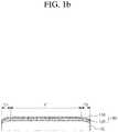
- FIGS. 1A and 1Bare a perspective view and a cross-sectional view for describing a glass protective film for covering a curved surface according to an exemplary embodiment of the present invention.
- a glass protective film 100 for covering a curved surfacemay protect a portable display 10 including a curved display area as well as a flat display area, for example, the entire display area of the portable display 10 which is applied to a smart phone.
- the glass protective film 100 for covering the curved surface according to an exemplary embodiment of the present inventionmay include a glass film member 110 and an adhesive layer 120.
- the glass film member 110may include a flat area portion F which is positioned at the center and substantially flat and one or more curved area portions C1 and C2 which are extended from an edge of the flat area portion F and formed by a curved surface.
- the flat area portion F and the curved area portions C1 and C2may be integrally formed.
- the flat area portion Fmay have a rectangular shape with a pair of long sides facing each other and a pair of short sides connecting the long sides to each other and is disposed on the flat display area among the display areas of the portable display 10 to protect the flat display area.
- the curved area portions C1 and C2include a first curved area portion C1 and a second curved area portion C2 which are extended from each of the long sides of the flat area portion F to have a predetermined width and formed of convex curved surfaces based on the display area of the portable display 10.
- Each of the first curved area portion C1 and the second curved area portion C2may have a curvature which is continuously changed so as not to form a discontinuous surface on an interface with the flat area portion F and is disposed on the curved display areas formed at both sides of the flat display area among the display areas of the portable display 10, respectively, to protect the curved display areas.
- the adhesive layer 120is positioned between the entire area of the lower surface of the glass film member 110 and the display area of the portable display 110 corresponding thereto to adhere the entire area of the lower surface of the glass film member 10 to the portable display 10. That is, the adhesive layer 120 may be positioned between the curved display area of the portable display 10 and the curved areas C1 and C2 of the glass film member 110 as well as between the flat display area of the portable display 10 and the flat area F of the glass film member 110.
- the adhering of the glass film member 110 to the portable display 10 or the display area of the portable display 10 by the adhesive layer 120is defined to include a case where the glass film member 110 is not only directly adhered to the display area of the portable display 10, but also adhered to another film or coating film (not illustrated) adhered to the display area of the portable display 10.
- an air layeris formed in an area without forming the adhesive layer 120 among areas between the glass film member 110 and the display area of the portable display 10 to deteriorate sensitivity of the portable display 10 for a user's touch and deteriorate a display characteristic of the portable display 10 in terms of a user which views the portable display 10 through the glass film member 110 due to a difference in an optical characteristic between the air layer and the adhesive layer 120.
- the entire area of the lower surface of the glass film member 110is adhered to the display area of the portable display 10 by using the adhesive layer 120 to prevent the touch sensitivity or the display characteristic from being deteriorated.
- the adhesive layer 120may be formed by coating an adhesive composition having fluidity on the display area of the portable display 10 and then loading the glass film member 110 on the display area of the portable display 10 to spread the adhesive composition to the entire area of the lower surface of the glass film member 110 by a weight of the glass film member 110, and curing the adhesive composition.
- the adhesive compositionmay be cured by photopolymerization or thermal polymerization.
- a curvature radius of the curved area of the glass film member 110 and a curvature radius of the curved display area of the portable display 10have different values within an available margin for each product, and thus the curvature radius of the curved display area of the portable display 10 is different from the curvature radius of the curved area of the glass film member 110 applied thereto.
- the adhesive membermay not adhere the entire area of the lower surface of the glass film member 110 to the portable display 10 to form a undesired air layer between the glass film member 110 and the display area of the portable display 10.
- the adhesive composition having fluidityis spread between the glass film member 110 and the portable display 10 and cured to adhere the glass film member 110 to the portable display 10 and adhere the entire area of the lower surface of the glass film member 110 to the portable display 10, thereby preventing the sensitivity for the user's touch and the display characteristic from being deteriorated as described above. That is, even though a distance between the glass film member 110 and the portable display 10 is not constant, a thickness thereof may be changed to compensate a difference therebetween, and thus the adhesive layer 120 formed above may adhere the entire area of the lower surface of the glass film member 110 to the portable display 10.
- the adhesive compositionmay have viscosity of about 1 to 500 cps.
- the viscosity of the adhesive compositionis less than 1 cps, there is a problem that the surface tension of the adhesive composition is very weak and thus the adhesive composition passes the area between the glass film member 110 and the portable display 10 to be spread to the outside of the glass film member 110.
- the viscosity of the adhesive compositionis greater than 500 cps, there is a problem that the fluidity of the adhesive composition is low and thus the adhesive composition is not spread to the entire area of the lower surface of the glass film member 110 only by a self-weight of the glass film member 110.
- the viscosity of the adhesive compositionmay have viscosity of about 10 to 250 cps, preferably.
- the adhesive compositionmay include a UV polymerizable oligomer and a photopolymerization initiator.
- the UV polymerizable oligomermay include one or more selected from a modified acrylic-based oligomer, a polyester-based oligomer, an epoxy-based oligomer, an urethane-based oligomer, a polyether-based oligomer, a polyacrylic-based oligomer, a silicon acrylate-based oligomer, and the like
- the photopolymerization initiatormay include one or more selected from a benzoin ether-based compound, amines compounds, an ⁇ -hydroxy ketone-based compound, a phenyl glyoxylate-based compound, an acyl phosphineoxide-based compound, and the like.
- the adhesive compositionmay further include a diluent.
- the diluentmay control the viscosity of the adhesive composition and improve a property of the adhesive layer 120 after curing.
- the diluentmay include one or more selected from a styrene monomer, a methylmethacrylate monomer, an ethylmethacrylate monomer, an n-butylmethacrylate monomer, an iso-butylmethacrylate monomer, a t-butylmethacrylate monomer, a vinylchloride monomer, a vinylacetate monomer, an acrylonitrile monomer, a 2-ethylhexylmethacrylate monomer, a laurylmethacrylate monomer, a methylacrylate monomer, an ethylacrylate monomer, an n-butylacrylate monomer, an iso-butylacrylate monomer, a 2-ethylhexylacrylate mono
- the adhesive compositionmay further include additives including a photosensitizer, a colorant, a thickening agent, a polymerization inhibitor, and the like.
- the content of the UV polymerizable oligomermay be about 50 to 80 wt%
- the content of the diluentmay be about 14 to 49 wt%
- the content of the photopolymerization initiatormay be about 0.5 to 5 wt%
- the content of the additivesmay be about 0.5 to 1 wt%.
- the glass film member 110will be described with reference to FIGS. 2 and 3 .
- FIG. 2is a cross-sectional view for describing a first exemplary embodiment of a glass film member illustrated in FIGS. 1A and 1B .
- a glass film member 110Amay include a glass layer 111A, a base layer 112A, and an adhesive layer 113A.
- the glass layer 111Amay be made of a known glass material and include the flat area F and the curved areas C1 and C2 as described above.
- the base layer 112Amay be made of a transparent polymer material, for example, polyethylene terephthalate (PET), acrylic resin, or the like, include the flat area F and the curved areas C1 and C2, and may be formed to cover the entire area of the lower surface of the glass layer 111A.
- PETpolyethylene terephthalate
- acrylic resinacrylic resin
- the adhesive layer 113Ais disposed between the glass layer 111A and the base layer 112A to adhere the glass layer 111A and the base layer 112A to each other.
- the material of the adhesive layer 113Ais not particularly limited thereto, and known adhesive materials may be used without limitation.
- the base layer 112A adhered to the glass layer 111A by the adhesive layer 113Amay be adhered to the display area of the portable display 10 by the adhesive layer 120 described above and prevent the glass layer 111A from being scattered when the glass layer 111A is damaged.
- an adhesion enhancing patternmay be formed on the lower surface of the base layer 112A which is adhered to the display area of the portable display 10.
- the adhesion enhancing patternmay have a structure in which protrusions and grooves positioned therebetween are continuously disposed.
- the protrusionsmay include doted patterns formed regularly or irregularly, linear patterns extended in one direction, lattice patterns, and the like.
- a method of forming the adhesion enhancing patternis not particularly limited thereto.
- the adhesion enhancing patternmay be formed a sand blasting process, a dry etching process, a wet etching process, and the like or formed by methods such as mold coating.
- a surface area of the lower surface of the base layer 112Ais increased to enhance the adhesion to the adhesive layer 120, and in the process of adhering the glass film member 110 to the portable display 10, the surface tension of the adhesive composition is increased to prevent the adhesive composition from being leaked to the outside of the glass film member 110.
- the lower surface of the base layer 112A with the adhesion enhancing patternmay have surface roughness Ra of about 0.1 to 10 ⁇ m.
- the surface roughness of the lower surface of the base layer 112Ais less than 0.1 ⁇ m, it is difficult to achieve the technical effects described above.
- the surface roughness of the lower surface of the base layer 112Ais greater than 10 ⁇ m, the thickness of the base layer 112A is excessively increased and a height difference between the adhesion enhancing patterns is excessively increased to prevent the adhesive composition from being uniformly spread and rather cause a problem that the adhesion is partially deteriorated.
- the glass film member 110further includes a water-repellent/oil-repellent pattern 114A which is formed with a predetermined width along an edge of the base layer 112A.
- the water-repellent/oil-repellent pattern 114Amay be formed of a material having both water repellency and oil repellency.
- the material having both water repellency and oil repellencymay be used as the material of the water-repellent/oil-repellent pattern 114A without limitation and is not particularly limited thereto.
- the water-repellent/oil-repellent pattern 114Amay be formed of a fluorinated polymeric material, such as polytetrafluoroethylene (PTFE), perfluoroalkoxy (PFA), fluorinated ethylene propylene (FEP), ethylene + tetrafluoroethylene (ETFE), an ethylene tetrafluoroethylene copolymer (ETEE), trichlorotrifluoroethylene (PCTFE), ethylene-chlorotrifluoroethylene (ECTFE), polyvinylidene fluoride (PVDF), and polyvinyl fluoride (PVF), or a non-fluorinated polymeric material, such as polyimide (PI), polyether ether ketone (PEEK), polyphenylene sulfide (PPS), polyamide (PA), polyacetal (POM), polyamide imide (PAI), polyether sulfone (PES), polyether imide (PEI), polycarbonate (PC), and poly
- the adhesive composition for forming the adhesive layer 120 of the present inventiongenerally has a hydrophilic or hydrophobic property, in the case of forming the water-repellent/oil-repellent pattern 114A which is formed with a predetermined width along an edge of the base layer 112A, in the process of adhering the glass film member 110 to the portable display 10, it is possible to more stably prevent the adhesive composition from being leaked to the outside of the glass film member 110.
- the water-repellent/oil-repellent pattern 114Amay be formed with a width of about 10 to 500 ⁇ m.
- the width of the water-repellent/oil-repellent pattern 114Ais less than 10 ⁇ m, processing cost of forming the water-repellent/oil-repellent pattern 114A is increased and it is difficult to achieve the technical effect.
- the adhesive between the glass film member 110 and the portable display 10is relatively decreased in the area with the water-repellent/oil-repellent pattern 114A and thus there is a problem that the detachment between the glass film member 110 and the portable display 10 is generated in the area.
- the water-repellent/oil-repellent pattern 114Amay be formed with a width of about 100 to 300 ⁇ m.
- the water-repellent/oil-repellent pattern 114Amay be formed with a predetermined width, for example, a width of about 10 to 500 ⁇ m from an edge of the opening to surround the opening.
- FIG. 3is a cross-sectional view for describing a second exemplary embodiment of a glass film member illustrated in FIGS. 1A and 1B .
- a glass film member 110Baccording to the second exemplary embodiment of present invention includes a glass layer 111B and a water-repellent/oil-repellent pattern 114B.
- the glass film member 110B according to the exemplary embodimentdoes not include the base layer 112A and the adhesive layer 113A of the glass film member 110A according to the first exemplary embodiment of present invention as illustrated in FIG. 2 , and the glass layer 111B may be directly adhered to the portable display 10 through the adhesive layer 120.
- the glass layer 111Bis substantially the same as the glass layer 111A of the glass film member 110 illustrated in FIG. 2 except that the adhesion enhancing pattern (not illustrated) described above may be formed on the lower surface, the duplicated detailed description therefor will be omitted.
- water-repellent/oil-repellent pattern 114Bis substantially the same as the water-repellent/oil-repellent pattern 114A of the glass film member 110 illustrated in FIG. 2 except that the water-repellent/oil-repellent pattern 114B is formed along the edge of the lower surface of the glass layer 111B, the duplicated detailed description therefor will be omitted.
- FIG. 4is a cross-sectional view for describing a third exemplary embodiment of a glass film member illustrated in FIGS. 1A and 1B .
- a glass film member 110Cmay include a glass layer 111C, a base layer 112C, an adhesive layer 113C, and a water-repellent/oil-repellent pattern 114C.
- the glass film member 110Cis substantially the same as the glass film member 110 described with reference to FIG. 2 except that the base layer 112C and the adhesive layer 113C are disposed below the glass layer 111C to expose the edge of the lower surface of the glass layer 111C with a predetermined width and the water-repellent/oil-repellent pattern 114C is formed on the exposed lower surface of the glass layer 114C, the duplicated detailed description therefor will be described.
- the base layer 112C and the adhesive layer 113Cmay expose the edge of the lower surface of the glass layer 111C by a width of about 10 to 500 ⁇ m, preferably about 100 to 300 ⁇ m.
- the exposed portion between the glass film member 110 and the portable display 10is convex to the outside by the surface tension.
- the surface tension of the adhesive compositionis broken and thus a problem that the adhesive composition is leaked to the outside of the glass film member 110 may occur.
- the problemmay be caused even in the case of adhering the glass film member 110 to the portable display 10 by using the device 1000 of adhering the glass protective film for covering the curved surface according to the exemplary embodiment of the present invention to be described with reference to FIGS. 5 to 8 .
- the base layer 112C and the adhesive layer 113Care formed to expose the edge of the lower surface of the glass layer 111C with a width of about 10 to 500 ⁇ m as described above, the exposed convex portion of the adhesive composition does not protrude to the outside of the glass layer 111C, and as a result, the adhesive composition contacts the device 1000 of adhering the glass protective film for covering the curved surface to prevent the adhesive composition from being leaked to the outside.
- FIG. 5is a cross-sectional view for describing a device of adhering a glass protective film for covering a curved surface according to another exemplary embodiment of the present invention
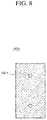
- FIGS. 6 to 8are plan views for describing a lower case, an upper case, and a coating member illustrated in FIG. 5 , respectively.
- the adhesive composition contacts the device 1000 of adhering the glass protective film for covering the curved surfaceincludes a lower case 1100, an upper case 1200, and a coating plate 1300.
- the lower case 1100may include a first support portion 1110 and a first partition wall portion 1120.
- the first support portion 1110may provide a fixing groove 1111 to which the portable display 10 may be inserted and fixed at the center and a first flat upper plane surrounding the fixing groove 1111.
- the fixing groove 1111may have a shape corresponding to the planar shape of the portable display 10 and have a depth smaller than a thickness of the portable display 10. While the portable display 10 inserted to the fixing groove 1111 is fixed so as not to move in a horizontal direction, the fixing groove 1111 may protrude from the first upper plane of the first support portion 1110 by a predetermined thickness.
- the shape of a first lower surface of the first support portion 1110 facing the first upper planeis not particularly limited thereto.
- the first partition wall portion 1120is disposed on the first upper plane of the first support portion 1110 to surround the fixing groove 1111 and may protrude from the first upper plane of the first support portion 1110 with a predetermined height.
- the first partition wall portion 1120may be formed to expose the fixing groove 1111 and the first upper plane by a predetermined width from the fixing groove 1111.
- the upper case 1200may include a second support portion 1210 and a second partition wall portion 1220.
- the second support portion 1210may provide a second lower plane which is supported in an area exposed by the first partition wall portion 1120 in the first upper plane of the first support portion 1110 and a second upper plane positioned on the second lower plane to face the second lower plane, and the fixing groove 1111 and an opening 1211 exposing the entire portable display 10 inserted thereto may be formed at the center.
- the second support portion 1210is inserted to the inside of the first partition wall portion 1120, and thus the second lower plane is supported by the first upper plane of the first support portion 1110 which is exposed by the first partition wall portion 1120 and an outer side connecting the second lower plane and the second upper side is supported by the inner surface of the first partition wall portion 1120 to be fixed so as not to move in the horizontal direction.
- the opening 1211 of the second support portion 1210may have the same planar shape as the fixing groove 1111, and the portable display 10 protruding from the first upper plane of the first support portion 1110 may be inserted and fixed to the opening 1211 of the second support portion 1210.
- the thickness of the second support portion 1210may be larger than the thickness of the portable display 10 at the portion protruding from the first upper plane.
- the second partition wall portion 1220is disposed on the second upper plane of the second support portion 1210 to surround the opening 1211 and may protrude from the second upper plane with a predetermined height.
- the second partition wall portion 1220may be formed to expose the opening 1211 and the second upper plane by a predetermined width from the opening 1211.
- the coating plate 1300may have a flat structure having a larger area than the fixing groove 1111 and is inserted to the inside of the second partition wall 1220 to support the lower surface by the second upper plane exposed by the second partition wall 1220, and one or more injection holes for injecting the adhesive composition may be formed at the center.
- the coating plate 1300may be disposed to be spaced apart from the display area of the portable display 10 at a predetermined interval.
- the side of the coating plate 1300is supported by the inner surface of the second partition wall 1220 to prevent the side of the coating plate 1300 from flowing in the horizontal direction.
- the method of adhering the glass protective film for covering the curved surfaceincludes coating an adhesive composition on a display area of a portable display 10; forming an adhesive composition layer between the portable display 10 and a glass film member 110 by loading the glass film member 110 on the display area of the portable display 10 on which the adhesive composition is coated; and curing the adhesive composition.
- the portable display 10is fixed to a fixing groove 1111 of the lower case 1100 and then the upper case 1200 may be inserted and fixed into the first partition wall 1120 of the lower case 1100.
- the coating plate 1300is inserted into the second partition wall 1220 of the upper case 1200 to be fixed to the top of the portable display 10 and thereafter, the adhesive composition may be coated on the display area of the portable display 10 through an injection hole 1301 of the coating plate 1300.
- the glass film member 110may be loaded on the display area of the portable display 10 through the opening 1211 of the second support portion 1210 of the upper case 1200.
- the adhesive compositionis dispersed and flows to the entire area between the glass film member 110 and the portable display 10 through capillarity by the weight of the glass film member 110 to form the adhesive composition layer. Meanwhile, when additional external force is not applied to the glass film member 110, the adhesive composition may not be leaked to the outside of the area between the glass film member 110 and the portable display 10 by the surface tension.
- the adhesive compositionmay be photo-cured or thermally cured.
- the photo-curing method and the thermal-curing method of the adhesive compositionare not particularly limited and known methods may be applied without limitation.
- the adhesive compositionwhen the adhesive composition is photo-cured, the adhesive composition may be cured by ultraviolet light, visible light, or infrared light irradiated from sun light, fluorescent light, LED light, a UV lamp, and the like.
- a fluidic adhesive compositionis dispersed and flows between the glass film member and the portable display to form and cure the adhesive composition layer and the glass film member is adhered to the portable display, even though the curvature of the curved display area and the curvature of the curved area of the glass film member in the portable display are different from each other, the entire area of the glass film member can be stably adhered to the portable display. As a result, deterioration of touch sensitivity or deterioration of the display characteristics which is caused by the air layer formed between the glass film member and the portable display is not generated.
- the adhesion enhancing patternon the surface which directly contacts the adhesive composition of the glass film member and forming the water-repellent/oil-repellent pattern along the edge of the surface, in the process of adhering the glass film member to the portable display, the adhesive composition is prevented from being leaked to the outside of the glass film member, thereby stably and easily adhering the glass film member to the portable display.
Landscapes
- Engineering & Computer Science (AREA)
- Physics & Mathematics (AREA)
- Computer Hardware Design (AREA)
- Theoretical Computer Science (AREA)
- General Physics & Mathematics (AREA)
- Chemical & Material Sciences (AREA)
- General Engineering & Computer Science (AREA)
- Organic Chemistry (AREA)
- Human Computer Interaction (AREA)
- Optics & Photonics (AREA)
- Microelectronics & Electronic Packaging (AREA)
- Computer Networks & Wireless Communication (AREA)
- Signal Processing (AREA)
- Chemical Kinetics & Catalysis (AREA)
- Life Sciences & Earth Sciences (AREA)
- General Chemical & Material Sciences (AREA)
- Geochemistry & Mineralogy (AREA)
- Materials Engineering (AREA)
- Devices For Indicating Variable Information By Combining Individual Elements (AREA)
- Laminated Bodies (AREA)
- Telephone Set Structure (AREA)
- Surface Treatment Of Glass (AREA)
- Adhesive Tapes (AREA)
Description
- The present invention relates to an assembly comprising a portable display including a flat display area and a curved display area and a glass protective film for covering a curved surface which is applied to said portable display, a method of adhering the same, and a method of adhering a glass protective film for covering a curved surface using the same. A tempered glass screen protector comprising a flat area portion and a curved area portion and having an adhesive layer for adhering to a screen of an electronic device is known from
EP 3 012 708 A1 . - In the case of portable displays including a touch screen type display such as a smart phone, since information is input through a user's screen touch, a risk that display areas of these devices are damaged by stabbing, pressing, scratch, and the like is high. In order to protect the portable display from the damage, various protective films are applied. Recently, tempered glass protection films having high hardness and an excellent protective function from external shocks have been widely used.
- Meanwhile, recently, while appearances of mobile devices are changed, portable displays having a flat display area and a curved display area and the like have been commercialized. In the portable display including the curved area, there is a limit that a protective film applied to the portable display having only a flat display area in the related art may not be applied as it is. Particularly, in the case of the glass protective film, even though glass is molded and prepared according to a curved surface of the portable display to be applied to the portable display, due to a limitation on a manufacturing process, a self-curvature of the portable display varies for each product and a curvature of the manufactured protective glass also varies for each product, and thus there is a problem in that the curved protective glass can not be applied to the portable curved display by the existing method.
- Therefore, development of a protective film for a curved cover glass which can be applied to the portable display having the curved display area has been urgently required.
- An object of the present invention is to provide an assembly comprising a portable display having a flat display area and a curved display area and a glass protective film for covering a curved surface which has a flat area and a curved area to be applied to the portable display and can stably adhere the flat area and the curved area to the display area of the portable display.
- Another object of the present invention is to a method of adhering the glass protective film for covering the curved surface to the portable display.
- According to an aspect of the present invention, provided is a glass protective film for covering a curved surface as defined in claim 1, which protects display areas of a portable display including a flat display area and a curved display area.
- Preferably, the adhesive composition may have viscosity of 1 to 500 mPa·s [cps].
- Preferably, the adhesive composition may include a UV polymerizable oligomer and a photopolymerization initiator. In this case, the UV polymerizable oligomer may include one or more selected from the group consisting of a modified acrylic-based oligomer, a polyester-based oligomer, an epoxy-based oligomer, an urethane-based oligomer, a polyether-based oligomer, a polyacrylic-based oligomer, and a silicon acrylate-based oligomer, and the photopolymerization initiator may include one or more selected from the group consisting of a benzoin ether-based compound, amines compounds, an α-hydroxy ketone-based compound, a phenyl glyoxylate-based compound, and an acyl phosphineoxide-based compound.
- Preferably, adhesive composition may further include a diluent, and the diluent may include one or more selected from the group consisting of a styrene monomer, a methylmethacrylate monomer, an ethylmethacrylate monomer, an n-butylmethacrylate monomer, an iso-butylmethacrylate monomer, a t-butylmethacrylate monomer, a vinylchloride monomer, a vinylacetate monomer, an acrylonitrile monomer, a 2-ethylhexylmethacrylate monomer, a laurylmethacrylate monomer, a methylacrylate monomer, an ethylacrylate monomer, an n-butylacrylate monomer, an iso-butylacrylate monomer, a 2-ethylhexylacrylate monomer, an ethylene monomer, and an octadecylmethacrylate monomer; or one or more selected from the group consisting of acrylic acid, methacrylic acid, 2-hydroxyethylmethacrylate, 2-hydroxypropylmethacrylate, dimethylaminoethylmethacrylate, t-butylaminoethylmethacrylate, di-ethylaminoethylmethacrylate, glycidylmethacrylate, 2-hydroxyethylacrylate), 2-hydroxypropylacrylate, itaconic acid, maleicacid, acrylamide, and N-methylolacrylamide. In this case, in the adhesive composition, the content of the UV polymerizable oligomer may be 50 to 80 wt%, the content of the diluent may be14 to 49 wt%, and the content of the photopolymerization initiator may be 0.5 to 5 wt%.
- Preferably, the glass film member may include: a base layer including a polymer film covering the entire area of the lower surface of the glass layer; and an adhesive layer positioned between the glass layer and the base layer to adhere the glass layer and the base layer to each other, in which the adhesive layer may adhere the entire area of the lower surface of the base layer to the display area of the portable display.
- Preferably, an adhesion enhancing pattern having protrusions and grooves positioned therebetween may be formed on the lower surface of the base layer. As an example, the protrusions may include dotted patterns, linear patterns extended in one direction, or lattice patterns. In this case, the lower surface of the base layer may have surface roughness Ra of 0.1 to 10 µm.
- The water-repellent/oil-repellent pattern may include one or more materials selected from a group consisting of polytetrafluoroethylene (PTFE), perfluoroalkoxy (PFA), fluorinated ethylene propylene (FEP), ethylene + tetrafluoroethylene (ETFE), an ethylene tetrafluoroethylene copolymer (ETEE), trichlorotrifluoroethylene (PCTFE), ethylene-chlorotrifluoroethylene (ECTFE), polyvinylidene fluoride (PVDF), polyvinyl fluoride (PVF), polyimide (PI), polyether ether ketone (PEEK), polyphenylene sulfide (PPS), polyamide (PA), polyacetal (POM), polyamide imide (PAI), polyether sulfone (PES), polyether imide (PEI), polycarbonate (PC), and polyphenylene ether (PPE). For example, the water-repellent/oil-repellent pattern may have a width of 10 to 500 µm.
- Preferably, the glass film member may include: the glass layer including the flat area portion and the curved area portion; the base layer including a polymer film disposed below the glass layer to expose the edge area of the lower surface of the glass layer; and the adhesive layer positioned between the glass layer and the base layer to adhere the glass layer and the base layer to each other, in which the adhesive layer may adhere the entire area of the lower surface of the base layer to the display area of the portable display.
- According to another aspect of the present invention, provided is a device of adhering a glass protective film for covering a curved surface, the device including: a lower case which includes a first support portion having a fixing groove to which the portable display is inserted at the center and a first flat upper plane surrounding the fixing groove and a first partition wall portion which is disposed on the first upper plane to surround the fixing groove and protrudes from the first upper plane; an upper case which includes a second support portion which is inserted to the first partition wall portion, has a second lower plane supported by the first upper plane and a second upper plane facing the second lower plane, and has an opening exposing the entire area of the fixing groove formed at the center and a second partition wall portion which is disposed on the second upper plane to surround the opening and protrudes from the second upper plane; and a coating plate which has a flat structure with a larger area than that of the fixing groove, is inserted to the inside of the second partition wall portion to be supported by the second upper plane to be positioned on the portable display, and has one or more injection holes for injecting the adhesive composition which are formed at the center.
- Preferably, the depth of the fixing groove may be smaller than the thickness of the portable display, and a sum of the depth of the fixing groove and the thickness of the second support portion may be larger than the thickness of the portable display.
- According to yet another aspect of the present invention, provided is a method of adhering a glass protective film for covering a curved surface, the method including: coating an adhesive composition on a display area of a portable display; loading a glass film member on the display area of the portable display coated with the adhesive composition to disperse and flow the adhesive composition between the portable display and the glass film member; and curing the adhesive composition.
- Preferably, the adhesive composition may have viscosity of 1 to 500 mPa·s [cps], and in the case of loading the glass film member, the adhesive composition may be dispersed and flow to the entire area between the glass film member and the portable display through capillarity by the weight of the glass film member, or external loads or pressuring. In order to prevent generation of an air layer, the adhesive composition may be slantly loaded at an angle of about 30° or less, preferably, about 5° to 15° with respect to the flat display area of the portable display.
- As described above, according to the present invention, since a fluidic adhesive composition is dispersed and flows between the glass film member and the portable display to form and cure the adhesive composition layer and the glass film member is adhered to the portable display, even though the curvature of the curved display area and the curvature of the curved area of the glass film member in the portable display are different from each other, the entire area of the glass film member can be stably adhered to the portable display. As a result, deterioration of touch sensitivity or deterioration of the display characteristics which is caused by the air layer formed between the glass film member and the portable display is not generated. In addition, by a self leveling effect of the fluidic adhesive composition, the air layer is not generated around the edge of the area between the glass film member and the portable display and thus the adhesion strength between the glass film member and the portable display may also be improved.
- Further, in the present invention, by forming the adhesion enhancing pattern on the surface which directly contacts the adhesive composition of the glass film member and forming the water-repellent/oil-repellent pattern along the edge of the surface, in the process of adhering the glass film member to the portable display, the adhesive composition is prevented from being leaked to the outside of the glass film member, thereby stably and easily adhering the glass film member to the portable display.
FIGS. 1A and1B are a perspective view and a cross-sectional view for describing a glass protective film for covering a curved surface according to an exemplary embodiment of the present invention.FIG. 2 is a cross-sectional view for describing a first exemplary embodiment of a glass film member illustrated inFIGS. 1A and1B .FIG. 3 is a cross-sectional view for describing a second exemplary embodiment of a glass film member illustrated inFIGS. 1A and1B .FIG. 4 is a cross-sectional view for describing a third exemplary embodiment of a glass film member illustrated inFIGS. 1A and1B .FIG. 5 is a cross-sectional view for describing a device of adhering a glass protective film for covering a curved surface according to another exemplary embodiment of the present invention.FIG. 6 is a plan view for describing a lower case illustrated inFIG. 5 .FIG. 7 is a plan view for describing an upper case illustrated inFIG. 5 .FIG. 8 is a plan view for describing a coating member illustrated inFIG. 5 .- Hereinafter, an exemplary embodiment of the present invention will be described in more detail with reference to the accompanying drawings. The present invention may be variously modified and have various exemplary embodiments, so that specific embodiments will be illustrated in the drawings and described in the detailed description. However, this does not limit the present invention within specific exemplary embodiments, and it should be understood that the present invention covers all the modifications, equivalents and replacements within the idea and technical scope of the present invention. In the description of each drawing, similar reference numerals are used for similar constitute elements. In the accompanying drawings, dimensions of structures are illustrated to be more enlarged than actual dimensions for clarity of the present invention.
- Terms such as first or second may be used to describe various components but the components are not limited by the above terminologies. The above terms are used only to discriminate one component from the other component. For example, a first element may be named a second element without departing from the scope of the present invention. Likewise, a second element may be named a first element.
- Terms used in the present application are used only to describe specific exemplary embodiments, and are not intended to limit the present invention. Singular expressions used herein include plurals expressions unless they have definitely opposite meanings. In the present application, it should be understood that term "include" or "have" indicates that a feature, a number, a step, an operation, a component, a part or the combination thereof described in the specification is present, but does not exclude a possibility of presence or addition of one or more other features, numbers, steps, operations, components, parts or combinations, in advance.
- If it is not contrarily defined, all terms used herein including technological or scientific terms have the same meaning as those generally understood by a person with ordinary skill in the art. Terms defined in generally used dictionary shall be construed that they have meanings matching those in the context of a related art, and shall not be construed in ideal or excessively formal meanings unless they are clearly defined in the present application.
FIGS. 1A and1B are a perspective view and a cross-sectional view for describing a glass protective film for covering a curved surface according to an exemplary embodiment of the present invention.- Referring to
FIGS. 1A and1B , a glassprotective film 100 for covering a curved surface according to an exemplary embodiment of the present invention may protect aportable display 10 including a curved display area as well as a flat display area, for example, the entire display area of theportable display 10 which is applied to a smart phone. In the exemplary embodiment, the glassprotective film 100 for covering the curved surface according to an exemplary embodiment of the present invention may include aglass film member 110 and anadhesive layer 120. - The
glass film member 110 may include a flat area portion F which is positioned at the center and substantially flat and one or more curved area portions C1 and C2 which are extended from an edge of the flat area portion F and formed by a curved surface. The flat area portion F and the curved area portions C1 and C2 may be integrally formed. - The flat area portion F may have a rectangular shape with a pair of long sides facing each other and a pair of short sides connecting the long sides to each other and is disposed on the flat display area among the display areas of the
portable display 10 to protect the flat display area. - The curved area portions C1 and C2 include a first curved area portion C1 and a second curved area portion C2 which are extended from each of the long sides of the flat area portion F to have a predetermined width and formed of convex curved surfaces based on the display area of the
portable display 10. Each of the first curved area portion C1 and the second curved area portion C2 may have a curvature which is continuously changed so as not to form a discontinuous surface on an interface with the flat area portion F and is disposed on the curved display areas formed at both sides of the flat display area among the display areas of theportable display 10, respectively, to protect the curved display areas. - The
adhesive layer 120 is positioned between the entire area of the lower surface of theglass film member 110 and the display area of theportable display 110 corresponding thereto to adhere the entire area of the lower surface of theglass film member 10 to theportable display 10. That is, theadhesive layer 120 may be positioned between the curved display area of theportable display 10 and the curved areas C1 and C2 of theglass film member 110 as well as between the flat display area of theportable display 10 and the flat area F of theglass film member 110. In this specification, the adhering of theglass film member 110 to theportable display 10 or the display area of theportable display 10 by theadhesive layer 120 is defined to include a case where theglass film member 110 is not only directly adhered to the display area of theportable display 10, but also adhered to another film or coating film (not illustrated) adhered to the display area of theportable display 10. - When the
adhesive layer 120 adheres only a partial area of the lower surface of theglass film member 110 to the display area of theportable display 10, an air layer is formed in an area without forming theadhesive layer 120 among areas between theglass film member 110 and the display area of theportable display 10 to deteriorate sensitivity of theportable display 10 for a user's touch and deteriorate a display characteristic of theportable display 10 in terms of a user which views theportable display 10 through theglass film member 110 due to a difference in an optical characteristic between the air layer and theadhesive layer 120. However, in the present invention, the entire area of the lower surface of theglass film member 110 is adhered to the display area of theportable display 10 by using theadhesive layer 120 to prevent the touch sensitivity or the display characteristic from being deteriorated. - In the exemplary embodiment of the present invention, the
adhesive layer 120 may be formed by coating an adhesive composition having fluidity on the display area of theportable display 10 and then loading theglass film member 110 on the display area of theportable display 10 to spread the adhesive composition to the entire area of the lower surface of theglass film member 110 by a weight of theglass film member 110, and curing the adhesive composition. As an example, the adhesive composition may be cured by photopolymerization or thermal polymerization. - In general, due to a limitation on the manufacturing process, a curvature radius of the curved area of the
glass film member 110 and a curvature radius of the curved display area of theportable display 10 have different values within an available margin for each product, and thus the curvature radius of the curved display area of theportable display 10 is different from the curvature radius of the curved area of theglass film member 110 applied thereto. As a result, in the case of adhering theglass film member 110 to theportable display 10 by using a known adhesive member such as an adhesive film without fluidity, the adhesive member may not adhere the entire area of the lower surface of theglass film member 110 to theportable display 10 to form a undesired air layer between theglass film member 110 and the display area of theportable display 10. - However, in the present invention, as such, the adhesive composition having fluidity is spread between the
glass film member 110 and theportable display 10 and cured to adhere theglass film member 110 to theportable display 10 and adhere the entire area of the lower surface of theglass film member 110 to theportable display 10, thereby preventing the sensitivity for the user's touch and the display characteristic from being deteriorated as described above. That is, even though a distance between theglass film member 110 and theportable display 10 is not constant, a thickness thereof may be changed to compensate a difference therebetween, and thus theadhesive layer 120 formed above may adhere the entire area of the lower surface of theglass film member 110 to theportable display 10. - In an exemplary embodiment, the adhesive composition may have viscosity of about 1 to 500 cps. When the viscosity of the adhesive composition is less than 1 cps, there is a problem that the surface tension of the adhesive composition is very weak and thus the adhesive composition passes the area between the
glass film member 110 and theportable display 10 to be spread to the outside of theglass film member 110. When the viscosity of the adhesive composition is greater than 500 cps, there is a problem that the fluidity of the adhesive composition is low and thus the adhesive composition is not spread to the entire area of the lower surface of theglass film member 110 only by a self-weight of theglass film member 110. As an example, the viscosity of the adhesive composition may have viscosity of about 10 to 250 cps, preferably. - In an exemplary embodiment, the adhesive composition may include a UV polymerizable oligomer and a photopolymerization initiator.
- The UV polymerizable oligomer may include one or more selected from a modified acrylic-based oligomer, a polyester-based oligomer, an epoxy-based oligomer, an urethane-based oligomer, a polyether-based oligomer, a polyacrylic-based oligomer, a silicon acrylate-based oligomer, and the like, and the photopolymerization initiator may include one or more selected from a benzoin ether-based compound, amines compounds, an α-hydroxy ketone-based compound, a phenyl glyoxylate-based compound, an acyl phosphineoxide-based compound, and the like.
- Meanwhile, the adhesive composition may further include a diluent. The diluent may control the viscosity of the adhesive composition and improve a property of the
adhesive layer 120 after curing. The diluent may include one or more selected from a styrene monomer, a methylmethacrylate monomer, an ethylmethacrylate monomer, an n-butylmethacrylate monomer, an iso-butylmethacrylate monomer, a t-butylmethacrylate monomer, a vinylchloride monomer, a vinylacetate monomer, an acrylonitrile monomer, a 2-ethylhexylmethacrylate monomer, a laurylmethacrylate monomer, a methylacrylate monomer, an ethylacrylate monomer, an n-butylacrylate monomer, an iso-butylacrylate monomer, a 2-ethylhexylacrylate monomer, an ethylene monomer, an octadecylmethacrylate monomer, and the like, or one or more selected from acrylic acid, methacrylic acid, 2-hydroxyethylmethacrylate, 2-hydroxypropylmethacrylate, dimethylaminoethylmethacrylate, t-butylaminoethylmethacrylate, diethylaminoethylmethacrylate, glycidylmethacrylate, 2-hydroxyethylacrylate, 2-hydroxypropylacrylate, itaconic acid, maleicacid, acrylamide, N-methylolacrylamide, and the like. - Meanwhile, the adhesive composition may further include additives including a photosensitizer, a colorant, a thickening agent, a polymerization inhibitor, and the like.
- In an exemplary embodiment, when the polymerization composition includes the UV polymerizable oligomer, the diluent, the photopolymerization initiator, and the additives, the content of the UV polymerizable oligomer may be about 50 to 80 wt%, the content of the diluent may be about 14 to 49 wt%, the content of the photopolymerization initiator may be about 0.5 to 5 wt%, and the content of the additives may be about 0.5 to 1 wt%.
- Hereinafter, the
glass film member 110 will be described with reference toFIGS. 2 and3 . FIG. 2 is a cross-sectional view for describing a first exemplary embodiment of a glass film member illustrated inFIGS. 1A and1B .- Referring to
FIG. 2 , aglass film member 110A according to the first exemplary embodiment of present invention may include aglass layer 111A, abase layer 112A, and anadhesive layer 113A. - The
glass layer 111A may be made of a known glass material and include the flat area F and the curved areas C1 and C2 as described above. - The
base layer 112A may be made of a transparent polymer material, for example, polyethylene terephthalate (PET), acrylic resin, or the like, include the flat area F and the curved areas C1 and C2, and may be formed to cover the entire area of the lower surface of theglass layer 111A. - The
adhesive layer 113A is disposed between theglass layer 111A and thebase layer 112A to adhere theglass layer 111A and thebase layer 112A to each other. The material of theadhesive layer 113A is not particularly limited thereto, and known adhesive materials may be used without limitation. - In the
glass film member 110 having such a structure, thebase layer 112A adhered to theglass layer 111A by theadhesive layer 113A may be adhered to the display area of theportable display 10 by theadhesive layer 120 described above and prevent theglass layer 111A from being scattered when theglass layer 111A is damaged. - In an exemplary embodiment, an adhesion enhancing pattern (not illustrated) may be formed on the lower surface of the
base layer 112A which is adhered to the display area of theportable display 10. The adhesion enhancing pattern may have a structure in which protrusions and grooves positioned therebetween are continuously disposed. For example, the protrusions may include doted patterns formed regularly or irregularly, linear patterns extended in one direction, lattice patterns, and the like. A method of forming the adhesion enhancing pattern is not particularly limited thereto. For example, the adhesion enhancing pattern may be formed a sand blasting process, a dry etching process, a wet etching process, and the like or formed by methods such as mold coating. - As such, in the case of forming the adhesion enhancing pattern on the lower surface of the
base layer 112A contacting theadhesive layer 120, a surface area of the lower surface of thebase layer 112A is increased to enhance the adhesion to theadhesive layer 120, and in the process of adhering theglass film member 110 to theportable display 10, the surface tension of the adhesive composition is increased to prevent the adhesive composition from being leaked to the outside of theglass film member 110. In addition, in the present invention, since the entire area of the lower surface of thebase layer 112A is adhered to theportable display 10 by theadhesive layer 120, even though the adhesion enhancing pattern is formed on the lower surface of thebase layer 112A, problems of deterioration of display characteristics in which the adhesion enhancing pattern is viewed to the user or light transmittance is deteriorated may not occur. - As an example, the lower surface of the
base layer 112A with the adhesion enhancing pattern may have surface roughness Ra of about 0.1 to 10 µm. When the surface roughness of the lower surface of thebase layer 112A is less than 0.1 µm, it is difficult to achieve the technical effects described above. When the surface roughness of the lower surface of thebase layer 112A is greater than 10 µm, the thickness of thebase layer 112A is excessively increased and a height difference between the adhesion enhancing patterns is excessively increased to prevent the adhesive composition from being uniformly spread and rather cause a problem that the adhesion is partially deteriorated. - Meanwhile, in the exemplary embodiment of the present invention, the
glass film member 110 further includes a water-repellent/oil-repellent pattern 114A which is formed with a predetermined width along an edge of thebase layer 112A. - The water-repellent/oil-
repellent pattern 114A may be formed of a material having both water repellency and oil repellency. The material having both water repellency and oil repellency may be used as the material of the water-repellent/oil-repellent pattern 114A without limitation and is not particularly limited thereto. For example, the water-repellent/oil-repellent pattern 114A may be formed of a fluorinated polymeric material, such as polytetrafluoroethylene (PTFE), perfluoroalkoxy (PFA), fluorinated ethylene propylene (FEP), ethylene + tetrafluoroethylene (ETFE), an ethylene tetrafluoroethylene copolymer (ETEE), trichlorotrifluoroethylene (PCTFE), ethylene-chlorotrifluoroethylene (ECTFE), polyvinylidene fluoride (PVDF), and polyvinyl fluoride (PVF), or a non-fluorinated polymeric material, such as polyimide (PI), polyether ether ketone (PEEK), polyphenylene sulfide (PPS), polyamide (PA), polyacetal (POM), polyamide imide (PAI), polyether sulfone (PES), polyether imide (PEI), polycarbonate (PC), and polyphenylene ether (PPE). - Since the adhesive composition for forming the
adhesive layer 120 of the present invention generally has a hydrophilic or hydrophobic property, in the case of forming the water-repellent/oil-repellent pattern 114A which is formed with a predetermined width along an edge of thebase layer 112A, in the process of adhering theglass film member 110 to theportable display 10, it is possible to more stably prevent the adhesive composition from being leaked to the outside of theglass film member 110. - As an example, the water-repellent/oil-
repellent pattern 114A may be formed with a width of about 10 to 500 µm. When the width of the water-repellent/oil-repellent pattern 114A is less than 10 µm, processing cost of forming the water-repellent/oil-repellent pattern 114A is increased and it is difficult to achieve the technical effect. When the width of the water-repellent/oil-repellent pattern 114A is greater than 500 µm, the adhesive between theglass film member 110 and theportable display 10 is relatively decreased in the area with the water-repellent/oil-repellent pattern 114A and thus there is a problem that the detachment between theglass film member 110 and theportable display 10 is generated in the area. For example, the water-repellent/oil-repellent pattern 114A may be formed with a width of about 100 to 300 µm. - Meanwhile, when the
glass film member 110A includes an opening that exposes a touch button, a camera lens, or the like of the portable display, that is, the water-repellent/oil-repellent pattern 114A may be formed with a predetermined width, for example, a width of about 10 to 500 µm from an edge of the opening to surround the opening. FIG. 3 is a cross-sectional view for describing a second exemplary embodiment of a glass film member illustrated inFIGS. 1A and1B .- Referring to
FIG. 3 , aglass film member 110B according to the second exemplary embodiment of present invention includes aglass layer 111B and a water-repellent/oil-repellent pattern 114B. - The
glass film member 110B according to the exemplary embodiment does not include thebase layer 112A and theadhesive layer 113A of theglass film member 110A according to the first exemplary embodiment of present invention as illustrated inFIG. 2 , and theglass layer 111B may be directly adhered to theportable display 10 through theadhesive layer 120. - Since the
glass layer 111B is substantially the same as theglass layer 111A of theglass film member 110 illustrated inFIG. 2 except that the adhesion enhancing pattern (not illustrated) described above may be formed on the lower surface, the duplicated detailed description therefor will be omitted. - In addition, since the water-repellent/oil-repellent pattern 114B is substantially the same as the water-repellent/oil-
repellent pattern 114A of theglass film member 110 illustrated inFIG. 2 except that the water-repellent/oil-repellent pattern 114B is formed along the edge of the lower surface of theglass layer 111B, the duplicated detailed description therefor will be omitted. FIG. 4 is a cross-sectional view for describing a third exemplary embodiment of a glass film member illustrated inFIGS. 1A and1B .- Referring to
FIG. 4 , a glass film member 110C according to the third exemplary embodiment of the present invention may include aglass layer 111C, abase layer 112C, anadhesive layer 113C, and a water-repellent/oil-repellent pattern 114C. - Since the glass film member 110C according to the exemplary embodiment is substantially the same as the
glass film member 110 described with reference toFIG. 2 except that thebase layer 112C and theadhesive layer 113C are disposed below theglass layer 111C to expose the edge of the lower surface of theglass layer 111C with a predetermined width and the water-repellent/oil-repellent pattern 114C is formed on the exposed lower surface of theglass layer 114C, the duplicated detailed description therefor will be described. - The
base layer 112C and theadhesive layer 113C may expose the edge of the lower surface of theglass layer 111C by a width of about 10 to 500 µm, preferably about 100 to 300 µm. In the process of adhering the glass film member 110C on theportable display 10, in the adhesive composition for forming theadhesive layer 120, the exposed portion between theglass film member 110 and theportable display 10 is convex to the outside by the surface tension. In this case, when an external object contacts the exposed portion of the adhesive composition, the surface tension of the adhesive composition is broken and thus a problem that the adhesive composition is leaked to the outside of theglass film member 110 may occur. The problem may be caused even in the case of adhering theglass film member 110 to theportable display 10 by using thedevice 1000 of adhering the glass protective film for covering the curved surface according to the exemplary embodiment of the present invention to be described with reference toFIGS. 5 to 8 . When thebase layer 112C and theadhesive layer 113C are formed to expose the edge of the lower surface of theglass layer 111C with a width of about 10 to 500 µm as described above, the exposed convex portion of the adhesive composition does not protrude to the outside of theglass layer 111C, and as a result, the adhesive composition contacts thedevice 1000 of adhering the glass protective film for covering the curved surface to prevent the adhesive composition from being leaked to the outside. FIG. 5 is a cross-sectional view for describing a device of adhering a glass protective film for covering a curved surface according to another exemplary embodiment of the present invention andFIGS. 6 to 8 are plan views for describing a lower case, an upper case, and a coating member illustrated inFIG. 5 , respectively.- Referring to
FIGS. 5 to 8 , the adhesive composition contacts thedevice 1000 of adhering the glass protective film for covering the curved surface according to the exemplary embodiment of the present invention includes alower case 1100, anupper case 1200, and acoating plate 1300. - The
lower case 1100 may include afirst support portion 1110 and a firstpartition wall portion 1120. - The
first support portion 1110 may provide a fixinggroove 1111 to which theportable display 10 may be inserted and fixed at the center and a first flat upper plane surrounding the fixinggroove 1111. The fixinggroove 1111 may have a shape corresponding to the planar shape of theportable display 10 and have a depth smaller than a thickness of theportable display 10. While theportable display 10 inserted to the fixinggroove 1111 is fixed so as not to move in a horizontal direction, the fixinggroove 1111 may protrude from the first upper plane of thefirst support portion 1110 by a predetermined thickness. The shape of a first lower surface of thefirst support portion 1110 facing the first upper plane is not particularly limited thereto. - The first
partition wall portion 1120 is disposed on the first upper plane of thefirst support portion 1110 to surround the fixinggroove 1111 and may protrude from the first upper plane of thefirst support portion 1110 with a predetermined height. The firstpartition wall portion 1120 may be formed to expose the fixinggroove 1111 and the first upper plane by a predetermined width from the fixinggroove 1111. - The
upper case 1200 may include asecond support portion 1210 and a secondpartition wall portion 1220. - The
second support portion 1210 may provide a second lower plane which is supported in an area exposed by the firstpartition wall portion 1120 in the first upper plane of thefirst support portion 1110 and a second upper plane positioned on the second lower plane to face the second lower plane, and the fixinggroove 1111 and anopening 1211 exposing the entireportable display 10 inserted thereto may be formed at the center. - As an example, the
second support portion 1210 is inserted to the inside of the firstpartition wall portion 1120, and thus the second lower plane is supported by the first upper plane of thefirst support portion 1110 which is exposed by the firstpartition wall portion 1120 and an outer side connecting the second lower plane and the second upper side is supported by the inner surface of the firstpartition wall portion 1120 to be fixed so as not to move in the horizontal direction. Theopening 1211 of thesecond support portion 1210 may have the same planar shape as the fixinggroove 1111, and theportable display 10 protruding from the first upper plane of thefirst support portion 1110 may be inserted and fixed to theopening 1211 of thesecond support portion 1210. In order to support thecoating plate 1300 to be spaced apart from theportable display 10 at a predetermined interval, the thickness of thesecond support portion 1210 may be larger than the thickness of theportable display 10 at the portion protruding from the first upper plane. - The second
partition wall portion 1220 is disposed on the second upper plane of thesecond support portion 1210 to surround theopening 1211 and may protrude from the second upper plane with a predetermined height. The secondpartition wall portion 1220 may be formed to expose theopening 1211 and the second upper plane by a predetermined width from theopening 1211. - The
coating plate 1300 may have a flat structure having a larger area than the fixinggroove 1111 and is inserted to the inside of thesecond partition wall 1220 to support the lower surface by the second upper plane exposed by thesecond partition wall 1220, and one or more injection holes for injecting the adhesive composition may be formed at the center. - In
FIG. 8 , two injection holes are illustrated, but two or more injection holes may also be formed in thecoating plate 1300. In addition, as described above, since the thickness of thesecond support portion 1210 is larger than the thickness of theportable display 10 at the portion protruding from the first upper plane, thecoating plate 1300 may be disposed to be spaced apart from the display area of theportable display 10 at a predetermined interval. - Meanwhile, in the case of being inserted to the inside of the
second partition wall 1220, the side of thecoating plate 1300 is supported by the inner surface of thesecond partition wall 1220 to prevent the side of thecoating plate 1300 from flowing in the horizontal direction. - Hereinafter, a method of adhering the glass protective film to the
portable display 10 by using thedevice 1000 of adhering the glass protective film for covering the curved surface will be described. - The method of adhering the glass protective film for covering the curved surface according to the exemplary embodiment of the present invention includes coating an adhesive composition on a display area of a
portable display 10; forming an adhesive composition layer between theportable display 10 and aglass film member 110 by loading theglass film member 110 on the display area of theportable display 10 on which the adhesive composition is coated; and curing the adhesive composition. - In the coating of the adhesive composition on the display area of the
portable display 10, first, theportable display 10 is fixed to a fixinggroove 1111 of thelower case 1100 and then theupper case 1200 may be inserted and fixed into thefirst partition wall 1120 of thelower case 1100. Next, thecoating plate 1300 is inserted into thesecond partition wall 1220 of theupper case 1200 to be fixed to the top of theportable display 10 and thereafter, the adhesive composition may be coated on the display area of theportable display 10 through aninjection hole 1301 of thecoating plate 1300. - In the forming of the adhesive composition layer between the
glass film member 110 and theportable display 10 by loading theglass film member 110 on the display area of theportable display 10 coated with the adhesive composition, first, after thecoating plate 1300 is removed from theupper case 1200, theglass film member 110 may be loaded on the display area of theportable display 10 through theopening 1211 of thesecond support portion 1210 of theupper case 1200. In the case of loading theglass film member 110 on the display area of theportable display 10 coated with the adhesive composition, the adhesive composition is dispersed and flows to the entire area between theglass film member 110 and theportable display 10 through capillarity by the weight of theglass film member 110 to form the adhesive composition layer. Meanwhile, when additional external force is not applied to theglass film member 110, the adhesive composition may not be leaked to the outside of the area between theglass film member 110 and theportable display 10 by the surface tension. - In the curing of the adhesive composition, the adhesive composition may be photo-cured or thermally cured. The photo-curing method and the thermal-curing method of the adhesive composition are not particularly limited and known methods may be applied without limitation. For example, when the adhesive composition is photo-cured, the adhesive composition may be cured by ultraviolet light, visible light, or infrared light irradiated from sun light, fluorescent light, LED light, a UV lamp, and the like.
- As described above, according to the present invention, since a fluidic adhesive composition is dispersed and flows between the glass film member and the portable display to form and cure the adhesive composition layer and the glass film member is adhered to the portable display, even though the curvature of the curved display area and the curvature of the curved area of the glass film member in the portable display are different from each other, the entire area of the glass film member can be stably adhered to the portable display. As a result, deterioration of touch sensitivity or deterioration of the display characteristics which is caused by the air layer formed between the glass film member and the portable display is not generated.
- Further, in the present invention, by forming the adhesion enhancing pattern on the surface which directly contacts the adhesive composition of the glass film member and forming the water-repellent/oil-repellent pattern along the edge of the surface, in the process of adhering the glass film member to the portable display, the adhesive composition is prevented from being leaked to the outside of the glass film member, thereby stably and easily adhering the glass film member to the portable display.
Claims (10)
- An assembly comprising a portable display (10) including a flat display area and a curved display area and a glass protective film (100)for covering a curved surface which protects display areas of said portable display (10), the glass protective film (100A, 100B, 100C) comprising:a glass film member (110A, 110B, 110C) including
a glass layer (lllA, 111B, 111C) including a flat area portion and a curved area portion, the curved area portion including a curved surface extended from the edge of the flat area portion; anda first adhesive layer (120) which is formed by spreading and curing an adhesive composition having fluidity between the entire area of the lower surface of the glass film member (110A, 110B, 110C) and the display area of the portable display (10) and adheres the entire area of the lower surface of the glass film member (110A, 110B, 110C) to the display area of the portable display,characterized in thatthe glass protective film (100) further includes a water-repellent/oil-repellent pattern (114A) preventing the adhesive composition from being leaked to the outside of the glass film member (110A, 110B, 110C), which pattern is formed along the edge of the glass film member (110A, 110B, 110C) and made of a polymer material having both water repellency and oil repellency. - The assembly of claim 1, wherein the adhesive composition has viscosity of 1 to 500 mPa·s [cps].
- The assembly of claim 1 or 2, wherein the adhesive composition includes a UV polymerizable oligomer and a photopolymerization initiator.
- The assembly_of claim 3, wherein the UV polymerizable oligomer includes one or more selected from the group consisting of a modified acrylic-based oligomer, a polyester-based oligomer, an epoxy-based oligomer, an urethane-based oligomer, a polyether-based oligomer, a polyacrylic-based oligomer, and a silicon acrylate-based oligomer, and
the photopolymerization initiator includes one or more selected from the group consisting of a benzoin ether-based compound, amines compounds, an α-hydroxy ketone-based compound, a phenyl glyoxylate-based compound, and an acyl phosphineoxide-based compound. - The assembly of any of claims 1 to 4, wherein the adhesive composition further includes a diluent, and the diluent includes one or more selected from the group consisting of a styrene monomer, a methylmethacrylate monomer, an ethylmethacrylate monomer, an n-butylmethacrylate monomer, an iso-butylmethacrylate monomer, a t-butylmethacrylate monomer, a vinylchloride monomer, a vinylacetate monomer, an acrylonitrile monomer, a 2-ethylhexylmethacrylate monomer, a laurylmethacrylate monomer, a methylacrylate monomer, an ethylacrylate monomer, an n-butylacrylate monomer, an iso-butylacrylate monomer, a 2-ethylhexylacrylate monomer, an ethylene monomer, and an octadecylmethacrylate monomer; or one or more selected from the group consisting of acrylic acid, methacrylic acid, 2-hydroxyethylmethacrylate, 2-hydroxypropylmethacrylate, dimethylaminoethylmethacrylate, t-butylaminoethylmethacrylate, diethylaminoethylmethacrylate, glycidylmethacrylate, 2-hydroxyethylacrylate, 2-hydroxypropylacrylate, itaconic acid, maleicacid, acrylamide, and N-methylolacrylamide.
- The assembly of any of claims 1 to 5, wherein an adhesion enhancing pattern having protrusions and grooves positioned therebetween is formed on the lower surface of the glass layer contacting the adhesive layer.
- The assembly of any of claims 1 to 5, wherein the glass film member (110A) further includes:a base layer (112A) including a polymer film covering the entire area of the lower surface of the glass layer; anda second adhesive layer (113A) positioned between the glass layer (111A) and the base layer (112A) to adhere the glass layer and the base layer to each other.
- The assembly of claim 7, wherein an adhesion enhancing pattern having protrusions and grooves positioned therebetween is formed on the lower surface of the base layer (112A).
- A method of forming an assembly according to one of claims 1 to 8 by adhering a glass protective film (100) for covering a curved surface to a portable display (10), the method comprising:coating an adhesive composition on a display area of the portable display (10);loading a glass film member (110) on the display area of the portable display coated with the adhesive composition to disperse and flow the adhesive composition between the portable display and the glass film member (110); andcuring the adhesive composition.
- The method of claim 9, wherein the adhesive composition has viscosity of 1 to 500 mPa·s [cps], and
in the case of loading the glass film member, the adhesive composition is dispersed and flows to the entire area between the glass film member and the portable display through capillarity by the weight of the glass film member.
Applications Claiming Priority (1)
| Application Number | Priority Date | Filing Date | Title |
|---|---|---|---|
| KR1020160091491AKR102038740B1 (en) | 2016-07-19 | 2016-07-19 | Glass protective film for covering a curved surface of a portable display, device of adhering the glass protective films to the curved surface of the portable display, and method of adhering the glass protective film to the curved surface using the device |
Publications (2)
| Publication Number | Publication Date |
|---|---|
| EP3272521A1 EP3272521A1 (en) | 2018-01-24 |
| EP3272521B1true EP3272521B1 (en) | 2022-03-30 |
Family
ID=56842629
Family Applications (1)
| Application Number | Title | Priority Date | Filing Date |
|---|---|---|---|
| EP16183424.7AActiveEP3272521B1 (en) | 2016-07-19 | 2016-08-09 | Glass protective film for covering a curved surface of a portable display and method of adhering the glass protective film to the curved surface |
Country Status (8)
| Country | Link |
|---|---|
| US (6) | US10684655B2 (en) |
| EP (1) | EP3272521B1 (en) |
| JP (1) | JP3207091U (en) |
| KR (1) | KR102038740B1 (en) |
| CN (1) | CN206085795U (en) |
| ES (1) | ES2917548T3 (en) |
| PL (1) | PL3272521T3 (en) |
| TW (1) | TWM537527U (en) |
Families Citing this family (49)
| Publication number | Priority date | Publication date | Assignee | Title |
|---|---|---|---|---|
| TW201815861A (en)* | 2016-07-07 | 2018-05-01 | 首威專業聚合物義大利公司 | Housing for portable device |
| KR102038740B1 (en)* | 2016-07-19 | 2019-10-31 | (주)화이트스톤 | Glass protective film for covering a curved surface of a portable display, device of adhering the glass protective films to the curved surface of the portable display, and method of adhering the glass protective film to the curved surface using the device |
| US20180065780A1 (en)* | 2016-09-06 | 2018-03-08 | Samsonite Ip Holdings S.Àr.L. | Case with internal graphic |
| CN113157125A (en) | 2017-01-03 | 2021-07-23 | 康宁公司 | Vehicle interior system with curved cover glass and display or touch panel and method of forming same |
| EP3572477A4 (en)* | 2017-01-17 | 2020-10-07 | Sekisui Chemical Co., Ltd. | MATERIAL FOR FILLING JOINT, PROTECTIVE FILM WITH MATERIAL FOR INFILLING JOINT, LAMINATED BODY, OPTICAL DEVICE AND PROTECTIVE PLATE FOR OPTICAL DEVICE |
| KR102301005B1 (en)* | 2017-03-21 | 2021-09-10 | 삼성전자 주식회사 | Protective film for electric device and window assembly using the same |
| KR20180109292A (en)* | 2017-03-27 | 2018-10-08 | (주)화이트스톤 | Display part protector for a smart device, device of adhering the display part protector to the surface of the display, and method of adhering the display part protector to the surface using the device |
| JP6877211B2 (en)* | 2017-03-30 | 2021-05-26 | デクセリアルズ株式会社 | Manufacturing method of optical equipment and optical equipment |
| KR101945861B1 (en)* | 2017-04-11 | 2019-04-29 | (주)화이트스톤 | Display protector attaching apparatus for smart device and the method having the same |
| CN107021610A (en)* | 2017-06-07 | 2017-08-08 | 吴秀兰 | It is used for the renovation technique of heat-bending glass surface smoothness always |
| CN107433752A (en)* | 2017-06-07 | 2017-12-05 | 吴秀兰 | Chip architecture and its manufacture method for the protection of curved surface electronic equipment screen |
| KR102002105B1 (en)* | 2017-07-14 | 2019-07-22 | (주)화이트스톤 | Display protector attaching apparatus for smart device and the method having the same |
| CN117962601A (en) | 2017-07-18 | 2024-05-03 | 康宁公司 | Cold forming of complex curved glass articles |
| US10292286B2 (en)* | 2017-07-31 | 2019-05-14 | Apple Inc. | Patterned glass layers in electronic devices |
| KR102035053B1 (en)* | 2017-08-04 | 2019-10-22 | (주)화이트스톤 | Display protector attaching apparatus for smart device and the method having the same |
| CN107364065B (en)* | 2017-08-14 | 2023-11-28 | 深圳市康利邦科技有限公司 | Integrated forming processing technology of curved glass screen protective film and protective film thereof |
| KR102574235B1 (en) | 2017-09-12 | 2023-09-11 | 코닝 인코포레이티드 | Tactile elements for deadfront glass and methods for manufacturing the same |
| KR102522575B1 (en)* | 2017-09-13 | 2023-04-17 | 삼성디스플레이 주식회사 | Window member and method for fabricating display device |
| US11065960B2 (en) | 2017-09-13 | 2021-07-20 | Corning Incorporated | Curved vehicle displays |
| TWI888167B (en) | 2017-10-10 | 2025-06-21 | 美商康寧公司 | Vehicle interior systems having a curved cover glass with improved reliability and methods for forming the same |
| CN207818084U (en)* | 2017-11-16 | 2018-09-04 | 华为技术有限公司 | A flexible cover, a flexible display device and a flexible terminal product |
| CN110161733A (en)* | 2018-02-14 | 2019-08-23 | 群创光电股份有限公司 | Show equipment and its manufacturing method |
| KR102169780B1 (en) | 2018-02-28 | 2020-10-26 | 삼성전자주식회사 | Apparatus for attaching protective film of electronic device and method of attaching protective film using the same |
| KR20190127161A (en)* | 2018-05-03 | 2019-11-13 | 엘지전자 주식회사 | Mobile terminal |
| KR101931481B1 (en)* | 2018-06-01 | 2018-12-20 | 주식회사 더하기 | Protection film structure and method for adhering the protective film to the portable display |
| KR102049770B1 (en) | 2018-06-22 | 2020-01-08 | 도우성 | UV-curable pressure-sensitive adhesive composition and curved surface sticking method thereof |
| KR102604280B1 (en) | 2018-07-31 | 2023-11-20 | 삼성전자주식회사 | Curved glass and electronic device including anti reflecting coating layer |
| KR102133641B1 (en)* | 2018-08-03 | 2020-07-21 | 도레이첨단소재 주식회사 | Adhesive film for surface protection and electronic member attached by the same |
| JP7015751B2 (en)* | 2018-08-22 | 2022-02-03 | エレコム株式会社 | Transparent film for mobile terminals |
| KR102179174B1 (en) | 2018-08-23 | 2020-11-16 | 주식회사 더하기 | Method for adhering the protective film to the portable display |
| KR102544326B1 (en)* | 2018-08-27 | 2023-06-19 | 삼성디스플레이 주식회사 | Display device |
| KR102609286B1 (en)* | 2018-09-21 | 2023-12-04 | 삼성디스플레이 주식회사 | Protection film for window of display device |
| KR102589499B1 (en)* | 2018-10-31 | 2023-10-13 | 엘지디스플레이 주식회사 | Flexible display apparatus and electronic device comprising the same |
| CN109410766B (en)* | 2018-12-18 | 2021-03-02 | 武汉天马微电子有限公司 | Display device and electronic equipment |
| KR102635565B1 (en)* | 2019-04-22 | 2024-02-13 | 삼성디스플레이 주식회사 | Window substrate, window substrate manufacturing method, and display module having the window substrate |
| CN110107844A (en)* | 2019-04-23 | 2019-08-09 | 扬州市李伟照明电器有限公司 | A kind of waterproof solar street lamp |
| KR102827635B1 (en)* | 2019-07-24 | 2025-07-04 | 삼성디스플레이 주식회사 | Display apparatus and method of manufacturing the same |
| US10981367B2 (en)* | 2019-09-10 | 2021-04-20 | Ping Zhang | Applicator device for a protector covering and its application |
| KR102308792B1 (en) | 2019-11-19 | 2021-10-05 | 도우성 | Viscosity-adjusted photocurable adhesive composition and its curved adhesive method |
| CN110922910A (en)* | 2019-12-12 | 2020-03-27 | 业成科技(成都)有限公司 | Film, electronic product and preparation method of film |
| US11199879B2 (en)* | 2019-12-31 | 2021-12-14 | Lenovo (Singapore) Pte. Ltd. | Computing device water protection |
| KR102825617B1 (en)* | 2020-01-30 | 2025-06-27 | 삼성디스플레이 주식회사 | Flexible pad for lamination process and method for manufacturing a display device using the same |
| JP7031830B2 (en)* | 2020-03-31 | 2022-03-08 | 株式会社オリジン | Manufacturing method of bonding member and bonding member manufacturing equipment |
| CN119575537A (en)* | 2020-04-07 | 2025-03-07 | 斯纳普公司 | Optical device and method for manufacturing an optical device |
| US12079036B2 (en)* | 2020-06-25 | 2024-09-03 | Apple Inc. | Electronic devices with molded display mounting structures |
| KR20220022950A (en) | 2020-08-19 | 2022-03-02 | 삼성디스플레이 주식회사 | Window module and method of manufacturing display device |
| JP6984934B1 (en)* | 2021-07-29 | 2021-12-22 | 株式会社Msソリューションズ | Protective sheet attachment tool for mobile terminals and how to attach the protective sheet |
| KR102516939B1 (en) | 2021-09-15 | 2023-04-04 | 주식회사 도우인시스 | UTG protective film lamination method including UTG folding test process |
| KR102516941B1 (en) | 2021-09-15 | 2023-04-04 | 주식회사 도우인시스 | UTG protective film lamination automation method |
Family Cites Families (43)
| Publication number | Priority date | Publication date | Assignee | Title |
|---|---|---|---|---|
| JP3195707B2 (en)* | 1994-02-24 | 2001-08-06 | 株式会社吉野工業所 | Moisture-proof container |
| JP3203955B2 (en)* | 1994-05-26 | 2001-09-04 | 松下電工株式会社 | Drain for eaves gutter |
| DE69526894T2 (en)* | 1994-09-26 | 2003-01-23 | Matsushita Electric Industrial Co., Ltd. | Liquid crystal display panel, method and device for the production thereof |
| KR101494459B1 (en)* | 2006-09-13 | 2015-02-17 | 스미또모 가가꾸 가부시끼가이샤 | Optical film coated with adhesive |
| KR20090099073A (en)* | 2006-12-25 | 2009-09-21 | 린텍 가부시키가이샤 | Display board for embedding pixel control element |
| JP5139736B2 (en)* | 2007-06-27 | 2013-02-06 | 東レエンジニアリング株式会社 | Liquid crystal component manufacturing method and manufacturing apparatus |
| JP2010117903A (en)* | 2008-11-13 | 2010-05-27 | Unon Giken:Kk | Method for manufacturing transparent touch panel input side transparent resin substrate |
| WO2010110135A1 (en) | 2009-03-23 | 2010-09-30 | Dic株式会社 | Adhesive protective film, screen panel, and portable electronic terminal |
| CN101724374A (en) | 2009-11-30 | 2010-06-09 | 北京海斯迪克新材料有限公司 | UV curing packaging adhesive for liquid crystal display |
| JP2013514553A (en) | 2009-12-17 | 2013-04-25 | スリーエム イノベイティブ プロパティズ カンパニー | Display panel assembly and manufacturing method thereof |
| KR101146994B1 (en)* | 2010-06-10 | 2012-05-22 | 삼성모바일디스플레이주식회사 | A display apparatus and a method for manufacturing the same |
| KR20120056788A (en)* | 2010-11-25 | 2012-06-04 | 니폰 쇼쿠바이 컴파니 리미티드 | Ultraviolet curable resin composition for optical use, cured product and display device |
| KR101351624B1 (en) | 2010-12-31 | 2014-01-15 | 제일모직주식회사 | Adhesive composition and a method for assembling module of mobile phone using the same |
| US20120180935A1 (en)* | 2011-01-19 | 2012-07-19 | Vannorden Jeffrey James | Robotic placement machine for optical bonding, system and method of use thereof |
| CN202190879U (en) | 2011-08-11 | 2012-04-18 | 陆民 | Full diamond cell-phone protective sheath |
| KR101300021B1 (en)* | 2011-09-05 | 2013-08-29 | 주식회사 토비스 | Method for manufacturing display panel with curved shape |
| SG11201401051WA (en) | 2011-09-28 | 2014-08-28 | 3M Innovative Properties Co | Method of coating liquid optically clear adhesives onto rigid substrates |
| US9516149B2 (en)* | 2011-09-29 | 2016-12-06 | Apple Inc. | Multi-layer transparent structures for electronic device housings |
| US9804305B2 (en)* | 2012-01-31 | 2017-10-31 | 3M Innovative Properties Company | Methods for sealing the edges of multi-layer articles |
| WO2013173976A1 (en) | 2012-05-22 | 2013-11-28 | Henkel (China) Company Limited | Liquid optically clear photo-curable adhesive |
| KR101178165B1 (en)* | 2012-05-22 | 2012-08-29 | 주식회사 슈피겐에스지피 | Protective films for portable electronic device using tempered glass |
| JP2014002246A (en)* | 2012-06-18 | 2014-01-09 | Sanko Soken Kk | Protective film affixing tool, film laminate and protective film affixing set |
| KR101422827B1 (en)* | 2012-09-11 | 2014-07-24 | 정종환 | Glass for protecting reinforced glass used in curved edges and manufacturing method thereof |
| JP5345239B1 (en) | 2012-11-13 | 2013-11-20 | オリジン電気株式会社 | Joining member manufacturing method and apparatus |
| EP2928974B1 (en) | 2012-12-10 | 2020-06-17 | 3M Innovative Properties Company | Liquid optical adhesive compositions |
| JP5370706B1 (en)* | 2012-12-14 | 2013-12-18 | デクセリアルズ株式会社 | Manufacturing method of image display device |
| CN203217885U (en)* | 2013-01-30 | 2013-09-25 | 索威斯胶带(上海)有限公司 | Display device and film assembly used for same |
| US9248628B2 (en)* | 2013-02-07 | 2016-02-02 | Solutia Inc. | Glass laminate using textured adhesive |
| KR101345149B1 (en)* | 2013-04-01 | 2013-12-26 | (주)아팩 | Acrylic pressure-sensitive adhesive composition, method for preparing thereof and surface protective film using it |
| CN103853382B (en) | 2014-02-17 | 2017-04-19 | 东莞万德电子制品有限公司 | Method for manufacturing waterproof anti-shock mobile phone touch screen |
| HUE052630T2 (en) | 2014-07-17 | 2021-05-28 | Henkel Ag & Co Kgaa | Photo-curable liquid optically clear adhesive composition and use thereof |
| KR101580502B1 (en)* | 2014-08-04 | 2015-12-31 | 패치웍스 주식회사 | Protective film using strengthened glass for display screen |
| US9298220B2 (en) | 2014-09-02 | 2016-03-29 | Samsung Electronics Co., Ltd. | Curved display and electronic device including the same |
| US9814151B2 (en) | 2014-09-26 | 2017-11-07 | Nlu Products, L.L.C. | Mobile electronic device faceplate border and related methods |
| KR102247283B1 (en)* | 2014-10-20 | 2021-05-03 | 삼성전자주식회사 | Electronic device and fabrication method for exterior member of the same |
| TWM504700U (en) | 2014-10-20 | 2015-07-11 | G Tech Optoelectronics Corp | Non-planar tempered glass protector for portable electronic devices |
| GB201419859D0 (en) | 2014-11-07 | 2014-12-24 | Rolls Royce Plc | No title listed |
| JP2016128866A (en) | 2015-01-09 | 2016-07-14 | 三菱電機株式会社 | Protection cover with sensor and image display apparatus |
| KR101602103B1 (en)* | 2015-05-07 | 2016-03-21 | 김영수 | Protecting sheet for touch screen panel having curved surface and method of manufacturing the sheet |
| JP5845370B1 (en)* | 2015-06-18 | 2016-01-20 | パナック株式会社 | Protective film sticking jig |
| PT3313948T (en) | 2015-06-25 | 2021-11-24 | Univ Do Minho | Method for bonding two layers with liquid adhesive and bonded assembly thereof |
| US20170094039A1 (en) | 2015-09-26 | 2017-03-30 | Liwei Lu | Touch screen protector |
| KR102038740B1 (en)* | 2016-07-19 | 2019-10-31 | (주)화이트스톤 | Glass protective film for covering a curved surface of a portable display, device of adhering the glass protective films to the curved surface of the portable display, and method of adhering the glass protective film to the curved surface using the device |
- 2016
- 2016-07-19KRKR1020160091491Apatent/KR102038740B1/enactiveActive
- 2016-08-02USUS15/226,683patent/US10684655B2/enactiveActive
- 2016-08-04TWTW105211754Upatent/TWM537527U/enunknown
- 2016-08-09ESES16183424Tpatent/ES2917548T3/enactiveActive
- 2016-08-09PLPL16183424.7Tpatent/PL3272521T3/enunknown
- 2016-08-09EPEP16183424.7Apatent/EP3272521B1/enactiveActive
- 2016-08-09JPJP2016003892Upatent/JP3207091U/enactiveActive
- 2016-08-10CNCN201620864435.5Upatent/CN206085795U/enactiveActive
- 2019
- 2019-04-11USUS16/381,932patent/US11320867B2/enactiveActive
- 2019-04-11USUS16/381,910patent/US11460889B2/enactiveActive
- 2019-09-30USUS16/588,459patent/US11513563B2/enactiveActive
- 2022
- 2022-04-26USUS17/729,969patent/US11853128B2/enactiveActive
- 2023
- 2023-11-08USUS18/388,080patent/US20240069603A1/enactivePending
Also Published As
| Publication number | Publication date |
|---|---|
| US20190239372A1 (en) | 2019-08-01 |
| US11460889B2 (en) | 2022-10-04 |
| US20180024594A1 (en) | 2018-01-25 |
| US11853128B2 (en) | 2023-12-26 |
| US10684655B2 (en) | 2020-06-16 |
| US20240069603A1 (en) | 2024-02-29 |
| US20190235580A1 (en) | 2019-08-01 |
| US11513563B2 (en) | 2022-11-29 |
| US20200089283A1 (en) | 2020-03-19 |
| KR20180009586A (en) | 2018-01-29 |
| US20220253108A1 (en) | 2022-08-11 |
| JP3207091U (en) | 2016-10-20 |
| US11320867B2 (en) | 2022-05-03 |
| KR102038740B1 (en) | 2019-10-31 |
| TWM537527U (en) | 2017-03-01 |
| ES2917548T3 (en) | 2022-07-08 |
| PL3272521T3 (en) | 2022-07-18 |
| EP3272521A1 (en) | 2018-01-24 |
| CN206085795U (en) | 2017-04-12 |
Similar Documents
| Publication | Publication Date | Title |
|---|---|---|
| US11853128B2 (en) | Glass protective film for covering a curved surface of a portable display, device of adhering the glass protective films to the curved surface of the portable display, and method of adhering the glass protective film to the curved surface using the device | |
| EP3381677A1 (en) | Display part protector for a smart device and method of adhering the display part protector to the surface using the device | |
| KR101938515B1 (en) | Protective film for covering a curved surface of a portable display, device of adhering the protective films to the curved surface of the portable display, and method of adhering the protective film to the curved surface using the device | |
| CN110462286A (en) | The light guide | |
| CN111696443A (en) | Display device | |
| US20190140210A1 (en) | Protective structure and electronic device | |
| US20220081353A1 (en) | Method for manufacturing window glass and carrier film used for the same | |
| US20170102497A1 (en) | Reflective display apparatus and front light module thereof | |
| CN106610513A (en) | Multilayer optical sheet assembly | |
| TW201819174A (en) | Optical component and method of manufacturing same | |
| TW201727270A (en) | Method for forming antireflection optical body, display panel and optical film | |
| TWI725088B (en) | Method for forming anti-reflection optical body | |
| KR102159642B1 (en) | Display part protector for a smart device | |
| US20160212249A1 (en) | Housing and method for manufacturing the same | |
| US7839572B2 (en) | Laminated lens package and method of fabricating the same | |
| KR20200103596A (en) | Display part protector for a smart device | |
| CN204650015U (en) | Thin light guide plate | |
| KR101954244B1 (en) | Cover Sheet Having Improved Adhesion for Curved Surface and Display Device Comprising the Same | |
| CN220951618U (en) | Protective film for touch screen | |
| WO2019142950A1 (en) | Liquid crystal screen protector for smart device and attaching device therefor | |
| KR20250131850A (en) | Release film and manufacturing method for same | |
| KR20160052972A (en) | Optical sheet and optical display device comprising the same |
Legal Events
| Date | Code | Title | Description |
|---|---|---|---|
| PUAI | Public reference made under article 153(3) epc to a published international application that has entered the european phase | Free format text:ORIGINAL CODE: 0009012 | |
| STAA | Information on the status of an ep patent application or granted ep patent | Free format text:STATUS: EXAMINATION IS IN PROGRESS | |
| 17P | Request for examination filed | Effective date:20160809 | |
| AK | Designated contracting states | Kind code of ref document:A1 Designated state(s):AL AT BE BG CH CY CZ DE DK EE ES FI FR GB GR HR HU IE IS IT LI LT LU LV MC MK MT NL NO PL PT RO RS SE SI SK SM TR | |
| AX | Request for extension of the european patent | Extension state:BA ME | |
| TPAC | Observations filed by third parties | Free format text:ORIGINAL CODE: EPIDOSNTIPA | |
| TPAC | Observations filed by third parties | Free format text:ORIGINAL CODE: EPIDOSNTIPA | |
| GRAP | Despatch of communication of intention to grant a patent | Free format text:ORIGINAL CODE: EPIDOSNIGR1 | |
| STAA | Information on the status of an ep patent application or granted ep patent | Free format text:STATUS: GRANT OF PATENT IS INTENDED | |
| INTG | Intention to grant announced | Effective date:20210629 | |
| GRAJ | Information related to disapproval of communication of intention to grant by the applicant or resumption of examination proceedings by the epo deleted | Free format text:ORIGINAL CODE: EPIDOSDIGR1 | |
| STAA | Information on the status of an ep patent application or granted ep patent | Free format text:STATUS: EXAMINATION IS IN PROGRESS | |
| GRAP | Despatch of communication of intention to grant a patent | Free format text:ORIGINAL CODE: EPIDOSNIGR1 | |
| STAA | Information on the status of an ep patent application or granted ep patent | Free format text:STATUS: GRANT OF PATENT IS INTENDED | |
| INTC | Intention to grant announced (deleted) | ||
| GRAS | Grant fee paid | Free format text:ORIGINAL CODE: EPIDOSNIGR3 | |
| INTG | Intention to grant announced | Effective date:20211125 | |
| GRAA | (expected) grant | Free format text:ORIGINAL CODE: 0009210 | |
| STAA | Information on the status of an ep patent application or granted ep patent | Free format text:STATUS: THE PATENT HAS BEEN GRANTED | |
| AK | Designated contracting states | Kind code of ref document:B1 Designated state(s):AL AT BE BG CH CY CZ DE DK EE ES FI FR GB GR HR HU IE IS IT LI LT LU LV MC MK MT NL NO PL PT RO RS SE SI SK SM TR | |
| REG | Reference to a national code | Ref country code:GB Ref legal event code:FG4D | |
| REG | Reference to a national code | Ref country code:CH Ref legal event code:EP | |
| REG | Reference to a national code | Ref country code:DE Ref legal event code:R096 Ref document number:602016070437 Country of ref document:DE | |
| REG | Reference to a national code | Ref country code:AT Ref legal event code:REF Ref document number:1478808 Country of ref document:AT Kind code of ref document:T Effective date:20220415 | |
| REG | Reference to a national code | Ref country code:IE Ref legal event code:FG4D | |
| REG | Reference to a national code | Ref country code:NL Ref legal event code:FP | |
| REG | Reference to a national code | Ref country code:ES Ref legal event code:FG2A Ref document number:2917548 Country of ref document:ES Kind code of ref document:T3 Effective date:20220708 | |
| REG | Reference to a national code | Ref country code:LT Ref legal event code:MG9D | |
| PG25 | Lapsed in a contracting state [announced via postgrant information from national office to epo] | Ref country code:SE Free format text:LAPSE BECAUSE OF FAILURE TO SUBMIT A TRANSLATION OF THE DESCRIPTION OR TO PAY THE FEE WITHIN THE PRESCRIBED TIME-LIMIT Effective date:20220330 Ref country code:RS Free format text:LAPSE BECAUSE OF FAILURE TO SUBMIT A TRANSLATION OF THE DESCRIPTION OR TO PAY THE FEE WITHIN THE PRESCRIBED TIME-LIMIT Effective date:20220330 Ref country code:NO Free format text:LAPSE BECAUSE OF FAILURE TO SUBMIT A TRANSLATION OF THE DESCRIPTION OR TO PAY THE FEE WITHIN THE PRESCRIBED TIME-LIMIT Effective date:20220630 Ref country code:LT Free format text:LAPSE BECAUSE OF FAILURE TO SUBMIT A TRANSLATION OF THE DESCRIPTION OR TO PAY THE FEE WITHIN THE PRESCRIBED TIME-LIMIT Effective date:20220330 Ref country code:HR Free format text:LAPSE BECAUSE OF FAILURE TO SUBMIT A TRANSLATION OF THE DESCRIPTION OR TO PAY THE FEE WITHIN THE PRESCRIBED TIME-LIMIT Effective date:20220330 Ref country code:BG Free format text:LAPSE BECAUSE OF FAILURE TO SUBMIT A TRANSLATION OF THE DESCRIPTION OR TO PAY THE FEE WITHIN THE PRESCRIBED TIME-LIMIT Effective date:20220630 | |
| REG | Reference to a national code | Ref country code:AT Ref legal event code:MK05 Ref document number:1478808 Country of ref document:AT Kind code of ref document:T Effective date:20220330 | |
| PG25 | Lapsed in a contracting state [announced via postgrant information from national office to epo] | Ref country code:LV Free format text:LAPSE BECAUSE OF FAILURE TO SUBMIT A TRANSLATION OF THE DESCRIPTION OR TO PAY THE FEE WITHIN THE PRESCRIBED TIME-LIMIT Effective date:20220330 Ref country code:GR Free format text:LAPSE BECAUSE OF FAILURE TO SUBMIT A TRANSLATION OF THE DESCRIPTION OR TO PAY THE FEE WITHIN THE PRESCRIBED TIME-LIMIT Effective date:20220701 Ref country code:FI Free format text:LAPSE BECAUSE OF FAILURE TO SUBMIT A TRANSLATION OF THE DESCRIPTION OR TO PAY THE FEE WITHIN THE PRESCRIBED TIME-LIMIT Effective date:20220330 | |
| PG25 | Lapsed in a contracting state [announced via postgrant information from national office to epo] | Ref country code:SM Free format text:LAPSE BECAUSE OF FAILURE TO SUBMIT A TRANSLATION OF THE DESCRIPTION OR TO PAY THE FEE WITHIN THE PRESCRIBED TIME-LIMIT Effective date:20220330 Ref country code:SK Free format text:LAPSE BECAUSE OF FAILURE TO SUBMIT A TRANSLATION OF THE DESCRIPTION OR TO PAY THE FEE WITHIN THE PRESCRIBED TIME-LIMIT Effective date:20220330 Ref country code:RO Free format text:LAPSE BECAUSE OF FAILURE TO SUBMIT A TRANSLATION OF THE DESCRIPTION OR TO PAY THE FEE WITHIN THE PRESCRIBED TIME-LIMIT Effective date:20220330 Ref country code:PT Free format text:LAPSE BECAUSE OF FAILURE TO SUBMIT A TRANSLATION OF THE DESCRIPTION OR TO PAY THE FEE WITHIN THE PRESCRIBED TIME-LIMIT Effective date:20220801 Ref country code:EE Free format text:LAPSE BECAUSE OF FAILURE TO SUBMIT A TRANSLATION OF THE DESCRIPTION OR TO PAY THE FEE WITHIN THE PRESCRIBED TIME-LIMIT Effective date:20220330 Ref country code:CZ Free format text:LAPSE BECAUSE OF FAILURE TO SUBMIT A TRANSLATION OF THE DESCRIPTION OR TO PAY THE FEE WITHIN THE PRESCRIBED TIME-LIMIT Effective date:20220330 Ref country code:AT Free format text:LAPSE BECAUSE OF FAILURE TO SUBMIT A TRANSLATION OF THE DESCRIPTION OR TO PAY THE FEE WITHIN THE PRESCRIBED TIME-LIMIT Effective date:20220330 | |
| PG25 | Lapsed in a contracting state [announced via postgrant information from national office to epo] | Ref country code:IS Free format text:LAPSE BECAUSE OF FAILURE TO SUBMIT A TRANSLATION OF THE DESCRIPTION OR TO PAY THE FEE WITHIN THE PRESCRIBED TIME-LIMIT Effective date:20220730 Ref country code:AL Free format text:LAPSE BECAUSE OF FAILURE TO SUBMIT A TRANSLATION OF THE DESCRIPTION OR TO PAY THE FEE WITHIN THE PRESCRIBED TIME-LIMIT Effective date:20220330 | |
| REG | Reference to a national code | Ref country code:DE Ref legal event code:R097 Ref document number:602016070437 Country of ref document:DE | |
| PG25 | Lapsed in a contracting state [announced via postgrant information from national office to epo] | Ref country code:DK Free format text:LAPSE BECAUSE OF FAILURE TO SUBMIT A TRANSLATION OF THE DESCRIPTION OR TO PAY THE FEE WITHIN THE PRESCRIBED TIME-LIMIT Effective date:20220330 | |
| PLBE | No opposition filed within time limit | Free format text:ORIGINAL CODE: 0009261 | |
| STAA | Information on the status of an ep patent application or granted ep patent | Free format text:STATUS: NO OPPOSITION FILED WITHIN TIME LIMIT | |
| 26N | No opposition filed | Effective date:20230103 | |
| PG25 | Lapsed in a contracting state [announced via postgrant information from national office to epo] | Ref country code:MC Free format text:LAPSE BECAUSE OF FAILURE TO SUBMIT A TRANSLATION OF THE DESCRIPTION OR TO PAY THE FEE WITHIN THE PRESCRIBED TIME-LIMIT Effective date:20220330 | |
| REG | Reference to a national code | Ref country code:CH Ref legal event code:PL | |
| PG25 | Lapsed in a contracting state [announced via postgrant information from national office to epo] | Ref country code:LU Free format text:LAPSE BECAUSE OF NON-PAYMENT OF DUE FEES Effective date:20220809 Ref country code:LI Free format text:LAPSE BECAUSE OF NON-PAYMENT OF DUE FEES Effective date:20220831 Ref country code:CH Free format text:LAPSE BECAUSE OF NON-PAYMENT OF DUE FEES Effective date:20220831 | |
| REG | Reference to a national code | Ref country code:BE Ref legal event code:MM Effective date:20220831 | |
| PG25 | Lapsed in a contracting state [announced via postgrant information from national office to epo] | Ref country code:SI Free format text:LAPSE BECAUSE OF FAILURE TO SUBMIT A TRANSLATION OF THE DESCRIPTION OR TO PAY THE FEE WITHIN THE PRESCRIBED TIME-LIMIT Effective date:20220330 | |
| REG | Reference to a national code | Ref country code:DE Ref legal event code:R082 Ref document number:602016070437 Country of ref document:DE Representative=s name:MAYR KOTSCH PATENTANWALT RECHTSANWAELTIN PARTN, DE | |
| PG25 | Lapsed in a contracting state [announced via postgrant information from national office to epo] | Ref country code:IE Free format text:LAPSE BECAUSE OF NON-PAYMENT OF DUE FEES Effective date:20220809 | |
| PG25 | Lapsed in a contracting state [announced via postgrant information from national office to epo] | Ref country code:BE Free format text:LAPSE BECAUSE OF NON-PAYMENT OF DUE FEES Effective date:20220831 | |
| PG25 | Lapsed in a contracting state [announced via postgrant information from national office to epo] | Ref country code:HU Free format text:LAPSE BECAUSE OF FAILURE TO SUBMIT A TRANSLATION OF THE DESCRIPTION OR TO PAY THE FEE WITHIN THE PRESCRIBED TIME-LIMIT; INVALID AB INITIO Effective date:20160809 | |
| PG25 | Lapsed in a contracting state [announced via postgrant information from national office to epo] | Ref country code:CY Free format text:LAPSE BECAUSE OF FAILURE TO SUBMIT A TRANSLATION OF THE DESCRIPTION OR TO PAY THE FEE WITHIN THE PRESCRIBED TIME-LIMIT Effective date:20220330 | |
| PG25 | Lapsed in a contracting state [announced via postgrant information from national office to epo] | Ref country code:MK Free format text:LAPSE BECAUSE OF FAILURE TO SUBMIT A TRANSLATION OF THE DESCRIPTION OR TO PAY THE FEE WITHIN THE PRESCRIBED TIME-LIMIT Effective date:20220330 | |
| PG25 | Lapsed in a contracting state [announced via postgrant information from national office to epo] | Ref country code:MT Free format text:LAPSE BECAUSE OF FAILURE TO SUBMIT A TRANSLATION OF THE DESCRIPTION OR TO PAY THE FEE WITHIN THE PRESCRIBED TIME-LIMIT Effective date:20220330 | |
| PGFP | Annual fee paid to national office [announced via postgrant information from national office to epo] | Ref country code:DE Payment date:20240807 Year of fee payment:9 | |
| PGFP | Annual fee paid to national office [announced via postgrant information from national office to epo] | Ref country code:GB Payment date:20240801 Year of fee payment:9 | |
| PGFP | Annual fee paid to national office [announced via postgrant information from national office to epo] | Ref country code:FR Payment date:20240812 Year of fee payment:9 | |
| PGFP | Annual fee paid to national office [announced via postgrant information from national office to epo] | Ref country code:PL Payment date:20240801 Year of fee payment:9 | |
| PGFP | Annual fee paid to national office [announced via postgrant information from national office to epo] | Ref country code:IT Payment date:20240802 Year of fee payment:9 | |
| PGFP | Annual fee paid to national office [announced via postgrant information from national office to epo] | Ref country code:NL Payment date:20250826 Year of fee payment:10 | |
| PGFP | Annual fee paid to national office [announced via postgrant information from national office to epo] | Ref country code:ES Payment date:20250902 Year of fee payment:10 |