EP3271539B1 - Motor vehicle door - Google Patents
Motor vehicle doorDownload PDFInfo
- Publication number
- EP3271539B1 EP3271539B1EP16719758.1AEP16719758AEP3271539B1EP 3271539 B1EP3271539 B1EP 3271539B1EP 16719758 AEP16719758 AEP 16719758AEP 3271539 B1EP3271539 B1EP 3271539B1
- Authority
- EP
- European Patent Office
- Prior art keywords
- motor vehicle
- drive
- door leaf
- opening
- vehicle door
- Prior art date
- Legal status (The legal status is an assumption and is not a legal conclusion. Google has not performed a legal analysis and makes no representation as to the accuracy of the status listed.)
- Active
Links
- 230000005540biological transmissionEffects0.000claimsdescription6
- 230000000694effectsEffects0.000description3
- 238000000034methodMethods0.000description2
- 230000001419dependent effectEffects0.000description1
- 230000002349favourable effectEffects0.000description1
- 238000004519manufacturing processMethods0.000description1
- 238000007789sealingMethods0.000description1
Images


Classifications
- E—FIXED CONSTRUCTIONS
- E05—LOCKS; KEYS; WINDOW OR DOOR FITTINGS; SAFES
- E05F—DEVICES FOR MOVING WINGS INTO OPEN OR CLOSED POSITION; CHECKS FOR WINGS; WING FITTINGS NOT OTHERWISE PROVIDED FOR, CONCERNED WITH THE FUNCTIONING OF THE WING
- E05F15/00—Power-operated mechanisms for wings
- E05F15/60—Power-operated mechanisms for wings using electrical actuators
- E05F15/603—Power-operated mechanisms for wings using electrical actuators using rotary electromotors
- E05F15/611—Power-operated mechanisms for wings using electrical actuators using rotary electromotors for swinging wings
- E05F15/616—Power-operated mechanisms for wings using electrical actuators using rotary electromotors for swinging wings operated by push-pull mechanisms
- E05F15/622—Power-operated mechanisms for wings using electrical actuators using rotary electromotors for swinging wings operated by push-pull mechanisms using screw-and-nut mechanisms
- E—FIXED CONSTRUCTIONS
- E05—LOCKS; KEYS; WINDOW OR DOOR FITTINGS; SAFES
- E05Y—INDEXING SCHEME ASSOCIATED WITH SUBCLASSES E05D AND E05F, RELATING TO CONSTRUCTION ELEMENTS, ELECTRIC CONTROL, POWER SUPPLY, POWER SIGNAL OR TRANSMISSION, USER INTERFACES, MOUNTING OR COUPLING, DETAILS, ACCESSORIES, AUXILIARY OPERATIONS NOT OTHERWISE PROVIDED FOR, APPLICATION THEREOF
- E05Y2900/00—Application of doors, windows, wings or fittings thereof
- E05Y2900/50—Application of doors, windows, wings or fittings thereof for vehicles
- E05Y2900/53—Type of wing
- E05Y2900/531—Doors
Definitions
- the inventionrelates to a motor vehicle door, in particular a handleless motor vehicle side door, according to the preamble of claim 1.
- Door leaves in motor vehicle doorsare regularly opened at least in gaps in order to facilitate the complete opening of the motor vehicle door in question.
- an operatorcan use the gap formed by the gap-wise opening of the door leaf between the motor vehicle body and the door leaf in order to reach behind the door leaf and pivot it open completely manually.
- DE 10 2011 015 669 A1so-called exhibitors for vehicle doors and vehicle flaps.
- the teaching according to the DE 10 2011 015 669 A1provides a lifting element for this purpose, which is activated by unlocking an associated lock.
- the lifting elementis designed in two parts and has an outer lever and an inner lever, which are designed to be pivotable or slidable relative to one another and, moreover, are releasably connected to a drive element.
- the inner leveris designed to pivot backwards in an anti-clockwise direction and the outer lever in a clockwise direction. In this way, an exhibitor is made available who can survive an immediate slamming of the associated motor vehicle door again without damage. This has proven itself, but is in need of improvement with regard to the design effort required for this.
- a device for electromotive actuation of a motor vehicle dooris described. This has an electric motor and a drive device with a connected connecting element to act on the door.
- the drive devicein turn has a friction device for transmitting a maximum drive torque.
- the connecting elementis at a distance from one or more rotary hinges for the door leaf connected to the motor vehicle body.
- US 2014 0 137 474 A1 , U.S. 3,220,414 A , FR 1 494 135 A , US 2014 0 150 581 A1 and US 2009 0 051 192 A1each describe a motor vehicle door according to the preamble of claim 1.
- the opening memberis pivotably attached to the motor vehicle body.
- the inventionis based on the technical problem of further developing such a motor vehicle door in such a way that a safe opening of the door leaf relative to the motor vehicle body is made available with structurally simple means, taking into account a gap sufficient for further handling.
- the inventionproposes a motor vehicle door, in particular a handleless motor vehicle side door, with a door leaf, at least one drive, and a push-out member connected to the drive for at least a gap opening of the door leaf with respect to a motor vehicle body, the push-out member connected to the drive being close to the axis in comparison a linear actuator arranged to an axis of rotation of the door leaf is formed; wherein the deployment member moves in the extended position against the motor vehicle body and thereby opens the door leaf at least in gaps; and wherein the deployment member does not bear against the motor vehicle body in the retracted position.
- the actuating elementis adjusted predominantly parallel to the longitudinal extension of the door leaf with the aid of the drive.
- the opening memberis arranged in the interior of the door leaf, that is, pointing in the direction of an interior of the motor vehicle body.
- the opening elementmoves against a wall of the motor vehicle body in this context, namely beyond the axis of rotation of the door leaf, ie as an extension of the door leaf beyond the axis of rotation.
- the named wall of the motor vehicle bodyis arranged predominantly perpendicular to the longitudinal extent of the door leaf or runs predominantly perpendicular to the longitudinal extent of the relevant door leaf.
- Such a wallis typically provided in the area of an opening in the motor vehicle body which is closed with the aid of the motor vehicle door according to the invention.
- the opening in question in the motor vehicle bodyis regularly equipped with the relevant and inwardly drawn in and circumferential wall, which is typically used for attaching a rubber door seal, fixing a locking bolt or lock holder and for fastening the axis of rotation of the door leaf defining hinges.
- the locking bolt or lock holderin turn interacts with a locking mechanism of a motor vehicle door lock.
- the motor vehicle door lockis regularly attached to the inside of the door leaf, so that when the door leaf is closed, the locking bolt moves into the locking mechanism and holds the door leaf and thus the motor vehicle door in place.
- the drive provided according to the inventionin conjunction with the opening element connected to the drive, ensures that the door leaf is opened at least in a gap with respect to the motor vehicle body.
- the deployment membercan advantageously be designed as a deployment ram which easily covers the previously described travel range of, for example, 10 mm to 20 mm.
- the opening elementis advantageously equipped with an adjusting rod.
- the control rodcan be of a Adjustment nut of the drive for linear adjustment are acted upon.
- the door leafalso has a motor vehicle door lock arranged on the inside.
- This motor vehicle door lockcan be a mechanical motor vehicle door lock, that is to say one in which the obligatory locking mechanism is opened mechanically, for example via a door handle and connected connecting elements.
- the motor vehicle door lock in questionis equipped with an associated lock drive and is consequently designed as an electric motor vehicle door lock or electric lock.
- the lock driveis generally an opening drive for the locking mechanism.
- the lock drivecan also be a drive, for example, for unlocking the motor vehicle door lock.
- the motor vehicle door lockcan be opened electrically. This means that in this case the lock drive regularly works on a pawl of the locking mechanism consisting of the rotary latch and pawl.
- the rotary latchcan open with the assistance of a spring.
- the locking bolt previously caught by the rotary latchis released.
- the door leaf and with it the entire motor vehicle dooris free and can be accessed by the the seal pressure built up in the door rubber seal can be exhibited slightly.
- the drive for the opening elementensures that the door leaf is subsequently opened with the aid of the opening element, at least in gaps.
- a control unitis regularly provided which only acts on the drive for the opening element when the lock in question in the motor vehicle door lock is opened.
- the locking mechanismmay be assigned a sensor that is queried by the control unit. If the sensor reports the opening of the locking mechanism, the drive for the opening element is acted upon in order to open the door leaf at least in gaps.
- the previously mentioned lock drive of the motor vehicle door lockalso functions as a drive for the opening member.
- the lock drivemay work on the actuating member by means of a transmission element.
- This transmission elementcan be a Bowden cable.
- the drive for the opening elementis implemented and on the other hand the lock drive for the motor vehicle door lock, which is usually designed as an opening drive for the locking mechanism.
- the inventionworks with only a few design elements, what the technological Effort and costs are reduced.
- the functional reliabilityis increased.
- the inventionessentially makes use of the fact that the gap-wise opening of the door leaf must be made available at the far end of the door leaf compared to its axis of rotation.
- This movement on the remote lever armcan be initiated by a much smaller adjusting movement on the nearby lever arm or close to the axis compared to the axis of rotation.
- the opening elementis designed as an opening ram and, within the scope of the linear adjustment described, performs an adjustment path of, for example, 10 mm to 20 mm.
- the drive and the opening memberare advantageously mounted inside the door leaf.
- the deployment member with the associated drivecould also be provided and arranged in the interior of the body.
- the mounting of the drive and the opening member inside the vehicle door or on the associated door leafhas proven to be particularly favorable, because then there is the further possibility of using the lock drive of an already mandatory vehicle door lock inside the vehicle door or on the door leaf as a drive to be able to use for the opening member. This is where the main advantages can be seen.
- a motor vehicle dooris shown in a schematic longitudinal section.
- the motor vehicle dooris not restrictively a handleless motor vehicle side door.
- the basic structure of the motor vehicle door or motor vehicle side dooris equipped with a door leaf 1 which is connected to a motor vehicle body 3 such that it can pivot via an axis of rotation 2.
- the axis of rotation 2is defined by one or more hinges with the aid of which the door leaf 1 is articulated to the motor vehicle body 3, specifically to a wall 16, which will be referred to in more detail below.
- the door leaf 1 in the Fig. 1Perform pivoting movements, indicated by a double arrow, in comparison to the axis of rotation 2.
- motor vehicle door lock 4which is shown in detail in FIG Figure 2A is shown.
- the motor vehicle door lock 4 inside the door leaf 1interacts with a locking bolt 5 connected to a B-pillar or generally the motor vehicle body 3.
- the motor vehicle door lock 4essentially has a locking mechanism 6, 7 in its interior, which consists of a rotary latch 6 and a pawl 7 composed.
- the locking bolt 5is also fixed on the circumferential wall 16 of the motor vehicle body 3.
- the motor vehicle door lock 4is designed as a so-called electric lock, which enables the locking mechanism 6, 7 to be opened electrically.
- the motor vehicle door lock 4also has a lock drive 8, 9 inside.
- the lock drive 8, 9is composed of an electric motor 8 on the one hand and a control disc 9 driven by the electric motor 8 on the other.
- control disk 9Depending on a rotational movement of the control disk 9 initiated by the electric motor 8, the control disk 9 works on the pawl 7 to move it to deliver from the rotary latch 6.
- the electric motor 8receives the corresponding command for this via an indicated control unit 10.
- the control unit 10may in turn receive the opening command via a door key, the approach of an operator ("keyless entry") or simply by the operator operating a door leaf.
- the permissible opening commandresults in the control unit 10 acting on the electric motor 8 in the sense that it opens the locking mechanism 6, 7 via the control disk 9 as described.
- the rotary latch 6can swing open, as shown in FIG Figure 2A is indicated by an arrow. This releases the previously caught locking bolt 5.
- the door leaf 1and with it the entire motor vehicle door.
- the rotary latch 6actuates one in the Figure 2A indicated sensor 11, which transmits the corresponding opening signal to the control unit 10.
- At least one further drive 12, 13 - besides the lock drive 8, 9 - is also providedis of particular importance for the invention.
- An opening element 14is connected to the drive 12, 13, which in the exemplary embodiment is an opening ram 14.
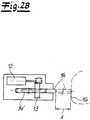
- the further drive 12, 13is shown in detail in FIG Figure 2B shown and in the context of Fig. 1 schematically as a box.
- the drive 12, 13 for the actuating member 14is composed of an electric motor 12 and an adjusting nut 13 in the exemplary embodiment.
- the opening element or the opening ram 14is for its part equipped with an adjusting rod 14 ′ which interacts with the adjusting nut 13.
- the adjusting rod 14 ′ of the deployment ram 14engages with its external thread in an internal thread of the adjusting nut 13.
- the electric motor 12sets the adjusting nut 13 in rotation, this has the effect that the adjusting rod 14 'and with it the entire deployment ram or the deployment member 14 in the Figure 2B indicated Can perform linear movements. Consequently, the actuating member 14 is designed as a linear actuator.
- the deployment member or the deployment ram 14moves against the motor vehicle body 3 in the extended position.
- the motor vehicle body 3is equipped in the area of an opening 15 of the motor vehicle body 3 closed with the aid of the door leaf 1 with the circumferential wall 16, which runs predominantly perpendicular to the longitudinal extent of the door leaf 1 and carries the already mentioned hinges for the door leaf 1 and the locking bolt 5.
- the wall 16 in questionis mostly still equipped with a circumferential rubber seal, not expressly shown.
- the deployment member 14is adjusted with the aid of the drive 12, 13 predominantly parallel to the longitudinal extension of the door leaf 1. That is in the Fig. 1 indicated by a corresponding double arrow, which is used to identify the adjustment path x of the actuating member 14.
- the adjustment path x realized at this pointis approximately 10 to 20 mm in the exemplary embodiment.
- the adjustment path x of the actuating element 14 in questionleads to significant and in the area of the lever effect at the end of the door leaf 1 remote from the axis compared to the axis of rotation 2 Fig. 1 indicated larger adjusting movements.
- a travel ywhich is approximately 50 mm to 100 mm.
- This adjustment path ycorresponds to an at least gap-wise opening of the door leaf 1 with respect to the motor vehicle body 3, which is reached and implemented with the aid of the opening element 14 connected to the drive 12, 13.
- the adjustment path y or the resulting gap-wise opening of the door leaf 1is usually sufficient for an operator to reach behind the door leaf 1 through the gap created and open it completely.
- the deployment member or the deployment ram 14is arranged close to the axis in comparison to the axis of rotation 2 and is otherwise adjusted parallel to the longitudinal extent of the door leaf 1.
- the deployment member 14can move against the wall 16 of the motor vehicle body 3 beyond the axis of rotation 2 of the door leaf 1, the wall 16 in question also running predominantly perpendicular to the longitudinal extension of the door leaf 1.
- a lock drive 8, 9 of the motor vehicle lock 4 on the one hand and a separate drive 12, 13 for the deployment member 14 on the other handare used.
- the lock drive or opening drive 8, 9also functions as a drive 8, 9 for the deployment member 14.
- the lock drive 8, 9with the help of one in the Fig. 1
- the transmission element 17 indicated by dashed linesis coupled to the actuating member 14.
- This transmission element 17can be a mechanical or electrical transmission element 17.
- a Bowden cablewill preferably be used at this point.
- the Bowden cablecan, for example, be acted upon by the motor vehicle door lock 4 or its drive 8, 9 in such a way that the adjusting nut 13 is set in rotation directly with the help of the Bowden cable or the mechanical connecting element 17, so that in this way the opening element or the opening ram 14 performs the desired linear adjustment taking into account the travel x. This is basically indicated.
- the control unit 10ensures that either the lock drive 8, 9 acts on the opening ram 14 as described or ensures that the separate and additional drive 12, 13 for the actuating member 14 is acted upon and extended in a corresponding sense.
- the door leaf 1is then opened, as desired, at least in gaps with respect to the motor vehicle body 3, so that the operator can easily and manually open the door leaf 1 and thus the entire motor vehicle door.
Landscapes
- Power-Operated Mechanisms For Wings (AREA)
- Lock And Its Accessories (AREA)
Description
Translated fromGermanDie Erfindung betrifft eine Kraftfahrzeugtür, insbesondere grifflose Kraftfahrzeug-Seitentür, gemäß dem Oberbegriff des Anspruchs 1.The invention relates to a motor vehicle door, in particular a handleless motor vehicle side door, according to the preamble of claim 1.
Die wenigstens spaltweise Öffnung von Türflügeln bei Kraftfahrzeugtüren erfolgt regelmäßig, um die vollständige Öffnung der betreffenden Kraftfahrzeugtür zu erleichtern. Insbesondere bei grifflosen Kraftfahrzeugtüren kann auf diese Weise ein Bediener den durch die spaltweise Öffnung des Türflügels gebildeten Spalt zwischen der Kraftfahrzeugkarosserie und dem Türflügel nutzen, um den Türflügel zu hintergreifen und vollständig manuell aufzuschwenken. Zu diesem Zweck beschreibt
Die Lehre nach der
Der Innenhebel ist entgegen dem Uhrzeigersinn und der Außenhebel im Uhrzeigersinn aktiv rückschwenkend ausgebildet. Auf diese Weise wird ein Aussteller zur Verfügung gestellt, der auch ein sofortiges Wiederzuschlagen der zugehörigen Kraftfahrzeugtür unbeschadet übersteht. Das hat sich bewährt, ist jedoch im Hinblick auf den hierfür notwendigen konstruktiven Aufwand verbesserungsbedürftig.The inner lever is designed to pivot backwards in an anti-clockwise direction and the outer lever in a clockwise direction. In this way, an exhibitor is made available who can survive an immediate slamming of the associated motor vehicle door again without damage. This has proven itself, but is in need of improvement with regard to the design effort required for this.
In
Der Stand der Technik hat sich grundsätzlich bewährt. Allerdings sind die bisher verfolgten Lösungen überwiegend konstruktiv aufwendig gestaltet. Das stand bisher einer flächendeckenden Verwendung im Wege. Eine solche ist jedoch vor dem Hintergrund des zunehmenden Einsatzes sogenannter Türschlösser mit EÖ-Öffnungsfunktion (elektrisch öffnen) wünschenswert.The state of the art has basically proven itself. However, the solutions that have been pursued so far are predominantly designed in a constructively complex manner. So far, this has stood in the way of widespread use. However, against the background of the increasing use of so-called door locks with EÖ opening function (open electrically), this is desirable.
Denn bei Kraftfahrzeugtüren mit den angesprochenen EÖ-Türschlössern besteht oftmals das Problem, dass nach dem elektrischen Öffnen des fraglichen Kraftfahrzeugtürschlosses der sich zwangsläufig einstellende Spalt zwischen dem Türflügel und der Kraftfahrzeugkarosserie nicht ausreicht, damit ein Bediener einwandfrei den Türflügel hintergreifen und öffnen kann. Dieses Phänomen beobachtet man insbesondere dann, wenn die üblicherweise für die spaltweise Öffnung des Türflügels in diesem Zusammenhang verantwortlich zeichnenden Gummidichtungen in ihrem aufgebauten Dichtungsdruck nachlassen. Außerdem können etwaige Fertigungstoleranzen beim Anbau des Türflügels an die Kraftfahrzeugkarosserie dazu führen, dass prinzipbedingt der sich auf diese Weise einstellende Öffnungsspalt von seiner Größe her grundsätzlich nicht ausreicht. Hier will die Erfindung insgesamt Abhilfe schaffen.Because with motor vehicle doors with the mentioned EÖ door locks there is often the problem that after the electrical opening of the motor vehicle door lock in question, the gap that is inevitably established between the door leaf and the vehicle body is not sufficient for an operator to be able to reach behind the door leaf and open it properly. This phenomenon is observed in particular when the rubber seals, which are usually responsible for the gap-wise opening of the door leaf in this context, decrease in their sealing pressure. In addition, any manufacturing tolerances when mounting the door leaf on the motor vehicle body can lead to the fact that the size of the opening gap that is established in this way is fundamentally insufficient. The invention aims to provide a remedy here overall.
Der Erfindung liegt das technische Problem zugrunde, eine derartige Kraftfahrzeugtür so weiter zu entwickeln, dass ein sichere Öffnung des Türflügels gegenüber der Kraftfahrzeugkarosserie unter Berücksichtigung eines für die weitere Handhabung ausreichenden Spaltes mit konstruktiv einfachen Mitteln zur Verfügung gestellt wird.The invention is based on the technical problem of further developing such a motor vehicle door in such a way that a safe opening of the door leaf relative to the motor vehicle body is made available with structurally simple means, taking into account a gap sufficient for further handling.
Die Erfindung schlägt den Gegenstand des Anspruchs 1 vor. Vorteilhafte Ausführungsformen der Erfindung sind in den abhängigen Ansprüchen beschrieben.The invention proposes the subject matter of claim 1. Advantageous embodiments of the invention are described in the dependent claims.
Die Erfindung schlägt eine Kraftfahrzeugtür, insbesondere eine grifflose Kraftfahrzeug-Seitentür, vor mit einem Türflügel, zumindest einem Antrieb, und einem an den Antrieb angeschlossenen Ausstellglied zur zumindest spaltweisen Öffnung des Türflügels gegenüber einer Kraftfahrzeugkarosserie, wobei das an den Antrieb angeschlossene Ausstellglied als achsnah im Vergleich zu einer Drehachse des Türflügels angeordnetes Linearstellglied ausgebildet ist; wobei das Ausstellglied in ausgefahrener Position gegen die Kraftfahrzeugkarosserie fährt und dadurch den Türflügel wenigstens spaltweise öffnet; und wobei das Ausstellglied in eingefahrener Position nicht an der Kraftfahrzeugkarosserie anliegt.The invention proposes a motor vehicle door, in particular a handleless motor vehicle side door, with a door leaf, at least one drive, and a push-out member connected to the drive for at least a gap opening of the door leaf with respect to a motor vehicle body, the push-out member connected to the drive being close to the axis in comparison a linear actuator arranged to an axis of rotation of the door leaf is formed; wherein the deployment member moves in the extended position against the motor vehicle body and thereby opens the door leaf at least in gaps; and wherein the deployment member does not bear against the motor vehicle body in the retracted position.
Dabei hat es sich bewährt, wenn das Ausstellglied mit Hilfe des Antriebes überwiegend parallel zur Längserstreckung des Türflügels verstellt wird. Außerdem ist das Ausstellglied im Innern des Türflügels angeordnet, also in Richtung auf einen Innenraum der Kraftfahrzeugkarosserie hinweisend.It has proven to be useful if the actuating element is adjusted predominantly parallel to the longitudinal extension of the door leaf with the aid of the drive. In addition, the opening member is arranged in the interior of the door leaf, that is, pointing in the direction of an interior of the motor vehicle body.
Tatsächlich hat es sich bewährt, wenn das Ausstellglied in diesem Zusammenhang gegen eine Wand der Kraftfahrzeugkarosserie fährt, und zwar jenseits der Drehachse des Türflügels, d. h. in Verlängerung des Türflügels über die Drehachse hinaus. Die genannte Wand der Kraftfahrzeugkarosserie ist dabei überwiegend senkrecht zur Längserstreckung des Türflügels angeordnet bzw. verläuft überwiegend senkrecht zur Längserstreckung des betreffenden Türflügels. Eine derartige Wand ist typischerweise im Bereich einer Öffnung der Kraftfahrzeugkarosserie vorgesehen, welche mit Hilfe der erfindungsgemäßen Kraftfahrzeugtür verschlossen wird. Denn die fragliche Öffnung in der Kraftfahrzeugkarosserie ist regelmäßig mit der betreffenden und nach innen eingezogenen sowie umlaufenden Wand ausgerüstet, die typischerweise zur Anbringung einer Türgummidichtung, Festlegung eines Schließbolzens bzw. Schlosshalters und zur Befestigung von die Drehachse des Türflügels definierenden Scharnieren dient.In fact, it has proven to be useful if the opening element moves against a wall of the motor vehicle body in this context, namely beyond the axis of rotation of the door leaf, ie as an extension of the door leaf beyond the axis of rotation. The named wall of the motor vehicle body is arranged predominantly perpendicular to the longitudinal extent of the door leaf or runs predominantly perpendicular to the longitudinal extent of the relevant door leaf. Such a wall is typically provided in the area of an opening in the motor vehicle body which is closed with the aid of the motor vehicle door according to the invention. Because the opening in question in the motor vehicle body is regularly equipped with the relevant and inwardly drawn in and circumferential wall, which is typically used for attaching a rubber door seal, fixing a locking bolt or lock holder and for fastening the axis of rotation of the door leaf defining hinges.
Der Schließbolzen bzw. Schlosshalter wechselwirkt seinerseits mit einem Gesperre eines Kraftfahrzeugtürschlosses. Das Kraftfahrzeugtürschloss ist dabei regelmäßig innenseitig am Türflügel angebracht, so dass beim Schließen des Türflügels der Schließbolzen in das Gesperre einfährt und den Türflügel und damit die Kraftfahrzeugtür festhält.The locking bolt or lock holder in turn interacts with a locking mechanism of a motor vehicle door lock. The motor vehicle door lock is regularly attached to the inside of the door leaf, so that when the door leaf is closed, the locking bolt moves into the locking mechanism and holds the door leaf and thus the motor vehicle door in place.
Sobald nun das Gesperre geöffnet wird, sorgt der erfindungsgemäß vorgesehene Antrieb in Verbindung mit dem an den Antrieb angeschlossenen Ausstellglied dafür, dass der Türflügel zumindest spaltweise gegenüber der Kraftfahrzeugkarosserie geöffnet wird. Hierunter ist im Rahmen der Erfindung ein Spalt zwischen dem betreffenden Türflügel und der Kraftfahrzeugkarosserie gemeint, welcher eine Größenordnung von in etwa 50 mm bis 100 mm aufweist, so dass ein Bediener problemlos mit seiner Hand den Türflügel hintergreifen und vollständig öffnen kann.As soon as the locking mechanism is opened, the drive provided according to the invention, in conjunction with the opening element connected to the drive, ensures that the door leaf is opened at least in a gap with respect to the motor vehicle body. In the context of the invention, this means a gap between the relevant door leaf and the motor vehicle body, which has a size of around 50 mm to 100 mm, so that an operator can easily reach behind the door leaf with his hand and open it completely.
Dabei reichen in der Regel geringfügige Stellbewegungen des Ausstellgliedes aus, um die zuvor beschriebene spaltweise Öffnung unter Berücksichtigung eines Spaltes von in etwa 50 mm bis 100 mm zu realisieren. Tatsächlich haben sich an dieser Stelle Stellwege des Ausstellgliedes von beispielsweise 10 mm bis 20 mm als ausreichend erwiesen. Das lässt sich im Kern darauf zurückführen, dass das Ausstellglied zunächst einmal achsnah im Vergleich zu der Drehachse des Türflügels angeordnet ist. Da der Spalt demgegenüber am achsfernen Ende des Türflügels gemessen wird, dort wo üblicherweise auch das Kraftfahrzeugtürschloss an den Türflügel angeschlossen ist, führen selbst geringe achsnahe Stellwege jenseits der Drehfalle dazu, dass der Türflügel am achsfernen Ende eine signifikante Stellbewegung aufgrund der Hebelwirkung vollführt.As a rule, slight adjusting movements of the opening element are sufficient to realize the gap-wise opening described above, taking into account a gap of approximately 50 mm to 100 mm. In fact, travel of the actuating member of, for example, 10 mm to 20 mm has proven to be sufficient at this point. This can essentially be traced back to the fact that the opening element is initially arranged close to the axis in comparison to the axis of rotation of the door leaf. Since the gap, on the other hand, is measured at the end of the door leaf remote from the axis, where the motor vehicle door lock is usually also connected to the door leaf, even small adjustment paths near the axis beyond the rotary latch mean that the door leaf at the end remote from the axis performs a significant positioning movement due to the lever effect.
Aus diesem Grund kann das Ausstellglied vorteilhaft als Ausstellstößel ausgebildet sein, der den zuvor beschriebenen Stellweg von beispielsweise 10 mm bis 20 mm unschwer absolviert. Zu diesem Zweck ist das Ausstellglied vorteilhaft mit einer Stellstange ausgerüstet. Die Stellstange kann von einer Stellmutter des Antriebes zur Linearverstellung beaufschlagt werden.For this reason, the deployment member can advantageously be designed as a deployment ram which easily covers the previously described travel range of, for example, 10 mm to 20 mm. For this purpose, the opening element is advantageously equipped with an adjusting rod. The control rod can be of a Adjustment nut of the drive for linear adjustment are acted upon.
Das heißt, mit Hilfe der Stellmutter des Antriebes wird die Stellstange linear verstellt. Dazu ist es lediglich erforderlich, dass die Stellmutter in Rotationen versetzt wird. Diese Rotationen der Stellmutter führen dazu, dass die mit der Stellmutter kämmende Stellstange entsprechend ein- oder ausgefahren wird. Dadurch lässt sich die Linearverstellung des Ausstellstößels bzw. des Ausstellgliedes unschwer realisieren.This means that the adjusting rod is adjusted linearly with the aid of the adjusting nut of the actuator. For this it is only necessary that the adjusting nut is set in rotation. These rotations of the adjusting nut cause the adjusting rod meshing with the adjusting nut to be extended or retracted accordingly. As a result, the linear adjustment of the deployment ram or of the deployment element can be easily implemented.
Wie bereits erläutert, verfügt der Türflügel zusätzlich über ein innenseitig angeordnetes Kraftfahrzeugtürschloss. Bei diesem Kraftfahrzeugtürschloss kann es sich um ein mechanisches Kraftfahrzeugtürschloss handeln, also ein solches, bei dem das obligatorische Gesperre auf mechanischem Wege beispielsweise über einen Türgriff und angeschlossene Verbindungselemente geöffnet wird. Nach besonders bevorzugter Ausführungsform ist das fragliche Kraftfahrzeugtürschloss jedoch mit einem zugehörigen Schlossantrieb ausgerüstet und folglich als elektrisches Kraftfahrzeugtürschloss bzw. Elektroschloss ausgebildet.As already explained, the door leaf also has a motor vehicle door lock arranged on the inside. This motor vehicle door lock can be a mechanical motor vehicle door lock, that is to say one in which the obligatory locking mechanism is opened mechanically, for example via a door handle and connected connecting elements. According to a particularly preferred embodiment, however, the motor vehicle door lock in question is equipped with an associated lock drive and is consequently designed as an electric motor vehicle door lock or electric lock.
Bei dem Schlossantrieb handelt es sich im Allgemeinen um einen Öffnungsantrieb für das Gesperre. Grundsätzlich kann es sich bei dem Schlossantrieb aber auch um einen Antrieb beispielsweise zur Entriegelung des Kraftfahrzeugtürschlosses handeln. Im Falle des auf das Gesperre arbeitenden Schlossantriebes lässt sich das Kraftfahrzeugtürschloss elektrisch öffnen. Das heißt, der Schlossantrieb arbeitet in diesem Fall regelmäßig auf eine Sperrklinke des Gesperres aus Drehfalle und Sperrklinke.The lock drive is generally an opening drive for the locking mechanism. In principle, however, the lock drive can also be a drive, for example, for unlocking the motor vehicle door lock. In the case of the lock drive working on the locking mechanism, the motor vehicle door lock can be opened electrically. This means that in this case the lock drive regularly works on a pawl of the locking mechanism consisting of the rotary latch and pawl.
Sobald der Schlossantrieb die Sperrklinke von der Drehfalle abhebt, kann die Drehfalle federunterstützt öffnen. Zugleich wird der zuvor von der Drehfalle gefangene Schließbolzen freigegeben. Als Folge hiervon ist dann auch der Türflügel und mit ihm die gesamte Kraftfahrzeugtür frei und kann durch den von der Türgummidichtung aufgebauten Dichtungsdruck geringfügig ausgestellt werden. Sobald das Gesperre im Kraftfahrzeugtürschloss geöffnet ist, sorgt erfindungsgemäß der Antrieb für das Ausstellglied dafür, dass im Anschluss hieran der Türflügel mit Hilfe des Ausstellgliedes zumindest spaltweise geöffnet wird.As soon as the lock drive lifts the pawl off the rotary latch, the rotary latch can open with the assistance of a spring. At the same time, the locking bolt previously caught by the rotary latch is released. As a result of this, the door leaf and with it the entire motor vehicle door is free and can be accessed by the the seal pressure built up in the door rubber seal can be exhibited slightly. As soon as the locking mechanism in the motor vehicle door lock is opened, according to the invention the drive for the opening element ensures that the door leaf is subsequently opened with the aid of the opening element, at least in gaps.
Dazu ist regelmäßig eine Steuereinheit vorgesehen, welche den Antrieb für das Ausstellglied erst dann beaufschlagt, wenn das fragliche Gesperre im Kraftfahrzeugtürschloss geöffnet ist. Dazu mag dem Gesperre ein Sensor zugeordnet sein, welcher von der Steuereinheit abgefragt wird. Meldet der Sensor die Öffnung des Gesperres, so wird der Antrieb für das Ausstellglied beaufschlagt, um den Türflügel zumindest spaltweise zu öffnen.For this purpose, a control unit is regularly provided which only acts on the drive for the opening element when the lock in question in the motor vehicle door lock is opened. For this purpose, the locking mechanism may be assigned a sensor that is queried by the control unit. If the sensor reports the opening of the locking mechanism, the drive for the opening element is acted upon in order to open the door leaf at least in gaps.
Im Rahmen einer besonders bevorzugten Ausführungsform der Erfindung fungiert der zuvor bereits angesprochene Schlossantrieb des Kraftfahrzeugtürschlosses zugleich auch als Antrieb für das Ausstellglied. In diesem Zusammenhang mag der Schlossantrieb mittels eines Übertragungselementes auf das Ausstellglied arbeiten. Bei diesem Übertragungselement kann es sich um einen Bowdenzug handeln. Diese Vorgehensweise ist besonders einfach gestaltet, weil lediglich ein einziger Antrieb für einerseits das elektrische Öffnen des Gesperres und damit des Kraftfahrzeugtürschlosses im Ganzen und andererseits das Ausstellen des Türflügels genutzt wird. Diese gleichsam doppelte Funktionalität des Schlossantriebes berücksichtigt, dass das elektrische Öffnen und das Ausstellen sukzessive und nacheinander erfolgen, so dass auf einen (einzigen) Antrieb für beide Vorgehensweisen zurückgegriffen werden kann.In the context of a particularly preferred embodiment of the invention, the previously mentioned lock drive of the motor vehicle door lock also functions as a drive for the opening member. In this context, the lock drive may work on the actuating member by means of a transmission element. This transmission element can be a Bowden cable. This procedure is particularly simple because only a single drive is used for the electrical opening of the locking mechanism and thus the motor vehicle door lock as a whole, and for opening the door leaf. This, as it were, double functionality of the lock drive takes into account that the electrical opening and opening take place successively and one after the other, so that one (single) drive can be used for both procedures.
Darüber hinaus ist es selbstverständlich alternativ oder auch zusätzlich möglich, dass einerseits der Antrieb für das Ausstellglied realisiert wird und andererseits der Schlossantrieb für das Kraftfahrzeugtürschloss, welcher im Regelfall als Öffnungsantrieb für das Gesperre ausgebildet ist. In jedem Fall arbeitet die Erfindung mit nur wenigen Konstruktionselementen, was den technologischen Aufwand und die Kosten verringert. Außerdem wird die Funktionssicherheit gesteigert.In addition, it is of course alternatively or additionally possible that on the one hand the drive for the opening element is implemented and on the other hand the lock drive for the motor vehicle door lock, which is usually designed as an opening drive for the locking mechanism. In any case, the invention works with only a few design elements, what the technological Effort and costs are reduced. In addition, the functional reliability is increased.
Dabei macht im Kern die Erfindung von der Tatsache Gebrauch, dass die spaltweise Öffnung des Türflügels am fernen Ende des Türflügels im Vergleich zu dessen Drehachse zur Verfügung gestellt werden muss. Diese Bewegung am fernen Hebelarm lässt sich durch eine viel geringere Stellbewegung am nahen Hebelarm bzw. achsnah im Vergleich zu der Drehachse initiieren. Dadurch reicht es aus, wenn das Ausstellglied als Ausstellstößel ausgebildet ist und im Rahmen der beschriebenen Linearverstellung einen Stellweg von beispielsweise 10 mm bis 20 mm vollführt.In this case, the invention essentially makes use of the fact that the gap-wise opening of the door leaf must be made available at the far end of the door leaf compared to its axis of rotation. This movement on the remote lever arm can be initiated by a much smaller adjusting movement on the nearby lever arm or close to the axis compared to the axis of rotation. As a result, it is sufficient if the opening element is designed as an opening ram and, within the scope of the linear adjustment described, performs an adjustment path of, for example, 10 mm to 20 mm.
Der Antrieb und auch das Ausstellglied sind vorteilhaft im Innern des Türflügels angebracht. Grundsätzlich könnte das Ausstellglied mit dem zugehörigen Antrieb aber auch im Innern der Karosserie vorgesehen werden und angeordnet sein. Erfindungsgemäß hat sich jedoch die Anbringung des Antriebes und des Ausstellgliedes im Innern im Kraftfahrzeugtür bzw. an dem zugehörigen Türflügel als besonders günstig erwiesen, weil dann die weitergehende Möglichkeit besteht, den Schlossantrieb eines ohnehin obligatorischen Kraftfahrzeugtürschlosses im Innern der Kraftfahrzeugtür bzw. am Türflügel zusätzlich als Antrieb für das Ausstellglied nutzen zu können. Hierin sind die wesentlichen Vorteile zu sehen.The drive and the opening member are advantageously mounted inside the door leaf. In principle, however, the deployment member with the associated drive could also be provided and arranged in the interior of the body. According to the invention, however, the mounting of the drive and the opening member inside the vehicle door or on the associated door leaf has proven to be particularly favorable, because then there is the further possibility of using the lock drive of an already mandatory vehicle door lock inside the vehicle door or on the door leaf as a drive to be able to use for the opening member. This is where the main advantages can be seen.
Im Folgenden wird die Erfindung anhand einer lediglich ein Ausführungsbeispiel darstellenden Zeichnung näher erläutert; es zeigen:
Fig. 1 den erfindungsgemäßen Türflügel in einem schematischen Längsschnitt undFig. 2A und2B Details aus derFig. 1 und zwar das Kraftfahrzeugtürschloss in einer Übersicht (Fig. 2A ) und den Antrieb mit angeschlossenem Ausstellglied (Fig. 2B ).
Fig. 1 the door leaf according to the invention in a schematic longitudinal section andFigure 2A and2 B Details from theFig. 1 namely the motor vehicle door lock in an overview (Figure 2A ) and the drive with attached extension element (Figure 2B ).
In der
Tatsächlich kann der Türflügel 1 in der
Im Ausführungsbeispiel nach der
Je nach einer von dem Elektromotor 8 initiierten Drehbewegung der Steuerscheibe 9 arbeitet die Steuerscheibe 9 auf die Sperrklinke 7, um diese von der Drehfalle 6 abzugeben. Den entsprechenden Befehl hierfür erhält der Elektromotor 8 über eine angedeutete Steuereinheit 10. Die Steuereinheit 10 mag wiederum den Öffnungsbefehl über einen Türschlüssel, die Annäherung eines Bedieners ("keyless entry") oder auch ganz einfach dadurch erhalten, dass der Bediener einen Türflügel betätigt.Depending on a rotational movement of the
Jedenfalls führt der zulässige Öffnungsbefehl dazu, dass die Steuereinheit 10 den Elektromotor 8 in dem Sinne beaufschlagt, dass dieser über die Steuerscheibe 9 das Gesperre 6, 7 wie beschrieben öffnet. Als Folge hiervon kann die Drehfalle 6 aufschwenken, wie dies in der
Von besonderer Bedeutung für die Erfindung ist nun noch der weitere Umstand, dass zusätzlich zumindest ein weiterer Antrieb 12, 13 - neben dem Schlossantrieb 8, 9 - vorgesehen ist. An den Antrieb 12, 13 ist ein Ausstellglied 14 angeschlossen, bei dem es sich im Ausführungsbeispiel um einen Ausstellstößel 14 handelt.The further fact that at least one
Der weitere Antrieb 12, 13 ist im Detail in der
Anhand der
Man erkennt anhand der
Da das Ausstellglied 14 als achsnah im Vergleich zu der Drehachse 2 des Türflügels 1 angeordnetes Linearstellglied ausgebildet ist, führt der fragliche Verstellweg x des Ausstellgliedes 14 aufgrund der Hebelwirkung am achsfernen Ende des Türflügels 1 im Vergleich zu der Drehachse 2 zu signifikanten und in der
Das alles lässt sich primär darauf zurückführen, dass das Ausstellglied bzw. der Ausstellstößel 14 achsnah im Vergleich zu der Drehachse 2 angeordnet ist und im Übrigen parallel zur Längserstreckung des Türflügels 1 verstellt wird. Dadurch kann das Ausstellglied 14 gegen die Wand 16 der Kraftfahrzeugkarosserie 3 fahren, und zwar jenseits der Drehachse 2 des Türflügels 1, wobei die fragliche Wand 16 darüber hinaus überwiegend senkrecht zur Längserstreckung des Türflügels 1 verläuft.All of this can primarily be attributed to the fact that the deployment member or the
Bei der bis jetzt beschriebenen Variante wird mit einerseits einem Schlossantrieb 8, 9 des Kraftfahrzeugschlosses 4 und andererseits einem separaten Antrieb 12, 13 für das Ausstellglied 14 gearbeitet. Es besteht aber auch die in der
Sofern eine mechanische Verbindung zwischen dem Schlossantrieb 8, 9 und dem Ausstellglied 14 realisiert ist, wird man an dieser Stelle bevorzugt mit einem Bowdenzug arbeiten. Der Bowdenzug kann dabei beispielsweise von dem Kraftfahrzeugtürschloss 4 bzw. dessen Antrieb 8, 9 derart beaufschlagt werden, dass mit Hilfe des Bowdenzuges bzw. des mechanischen Verbindungselementes 17 unmittelbar die Stellmutter 13 in Rotationen versetzt wird, damit auf diese Weise das Ausstellglied bzw. der Ausstellstößel 14 die gewünschte Linearverstellung unter Berücksichtigung des Stellweges x vollführt. Das ist grundsätzlich angedeutet.If a mechanical connection is implemented between the
Dabei wird man in beiden Fällen, d. h. bei einem separaten Antrieb 12, 13 für das Ausstellglied 14 ebenso wie für den Fall, dass der Schlossantrieb 8, 9 zugleich auch als Antrieb 8, 9 für das Ausstellglied 14 fungiert, so vorgehen, dass der Antrieb 8, 9 bzw. 12, 13 für das Ausstellglied 14 erst dann beaufschlagt wird, wenn das Gesperre 6, 7 im Kraftfahrzeugtürschloss 4 geöffnet ist. Dazu ist die Steuereinheit 10 in Verbindung mit dem Sensor 11 vorgesehen.In both cases, d. H. in the case of a
Das heißt, erst wenn der Sensor 11 ein entsprechendes Öffnungssignal an die Steuereinheit 10 abgibt, sorgt die Steuereinheit 10 dafür, dass entweder der Schlossantrieb 8, 9 den Ausstellstößel 14 wie beschrieben beaufschlagt oder sorgt dafür, dass der separate und zusätzliche Antrieb 12, 13 für das Ausstellglied 14 in entsprechendem Sinne beaufschlagt und ausgefahren wird. Als Folge hiervon wird dann der Türflügel 1 wunschgemäß wenigstens spaltweise gegenüber der Kraftfahrzeugkarosserie 3 geöffnet, so dass der Bediener den Türflügel 1 und damit die gesamte Kraftfahrzeugtür unschwer manuell vollständig öffnen kann.That is, only when the
Claims (9)
- Motor vehicle door, in particular a handle-less motor vehicle side door, comprising• a door leaf (1),• at least one drive (12, 13),• an opening member (14) connected to the drive (12, 13) for opening the door leaf (1) at least partially with respect to a motor vehicle body (3),• the opening member (14) being designed as a linear actuator which is arranged so as to be paraxial in relation to an axis of rotation (2) of the door leaf (1);
characterized in that• the opening member (14) moves against the motor vehicle body (3) in the extended position and thereby opens the door leaf (1) at least partially;• the opening member (14) does not abut the motor vehicle body (3) in the retracted position. - Motor vehicle door according to claim 1,characterized in that the opening member (14) is adjusted predominantly in parallel with the longitudinal extension of the door leaf (1) by means of the drive (12, 13).
- Motor vehicle door according to either of the preceding claims,characterized in that the opening member (14) moves against a wall (16) of the motor vehicle body (3), which wall extends beyond the axis of rotation (2) of the door leaf (1) and extends predominantly perpendicularly to the longitudinal extension of the door leaf (1).
- Motor vehicle door according to any of the preceding claims,characterized in that the opening member (14) is designed as an opening tappet (14).
- Motor vehicle door according to any of the preceding claims,characterized in that the opening member (14) is equipped with an adjusting rod (14') which is acted upon by an adjusting nut (12) of the drive (12, 13) for linear adjustment.
- Motor vehicle door according to any of the preceding claims,characterized in that the door leaf (1) is additionally equipped with a motor vehicle door latch (4) which has an associated latch drive (8, 9).
- Motor vehicle door according to the preceding claim,characterized in that the latch drive (8, 9) also acts as a drive (8, 9) for the opening member (14).
- Motor vehicle door according to either of the two preceding claims,characterized in that the latch drive (8, 9) acts on the opening member (14) by means of a transmission element (17), for example a Bowden cable.
- Motor vehicle door according to any of the preceding claims,characterized in that a control unit (10) is provided which only acts on the drive (12, 13; 8, 9) for the opening member (14) when a locking mechanism (6, 7) in the motor vehicle door latch (4) is open.
Applications Claiming Priority (2)
| Application Number | Priority Date | Filing Date | Title |
|---|---|---|---|
| DE102015103826.9ADE102015103826A1 (en) | 2015-03-16 | 2015-03-16 | Motor vehicle door |
| PCT/DE2016/100118WO2016146109A1 (en) | 2015-03-16 | 2016-03-15 | Motor vehicle door |
Publications (3)
| Publication Number | Publication Date |
|---|---|
| EP3271539A1 EP3271539A1 (en) | 2018-01-24 |
| EP3271539B1true EP3271539B1 (en) | 2020-09-16 |
| EP3271539B2 EP3271539B2 (en) | 2023-12-20 |
Family
ID=55862490
Family Applications (1)
| Application Number | Title | Priority Date | Filing Date |
|---|---|---|---|
| EP16719758.1AActiveEP3271539B2 (en) | 2015-03-16 | 2016-03-15 | Motor vehicle door |
Country Status (3)
| Country | Link |
|---|---|
| EP (1) | EP3271539B2 (en) |
| DE (1) | DE102015103826A1 (en) |
| WO (1) | WO2016146109A1 (en) |
Families Citing this family (9)
| Publication number | Priority date | Publication date | Assignee | Title |
|---|---|---|---|---|
| FR3078547A1 (en)* | 2018-03-05 | 2019-09-06 | Psa Automobiles Sa | VEHICLE EQUIPPED WITH A DEVICE FOR PARTIALLY OPENING AN OPENING COMPRISING AT LEAST ONE ELECTRIC LINEAR ACTUATOR |
| DE102018120284A1 (en)* | 2018-08-21 | 2020-02-27 | Kiekert Ag | Motor vehicle door unit |
| FR3086685B1 (en) | 2018-09-28 | 2020-12-04 | Psa Automobiles Sa | VEHICLE EQUIPPED WITH A DOOR OPENING DEVICE AND ASSOCIATED PROCESS |
| DE102021124089A1 (en) | 2021-09-17 | 2023-03-23 | Kiekert Aktiengesellschaft | Method for controlling at least one motor vehicle closure element |
| DE102022119852A1 (en) | 2022-08-08 | 2024-02-08 | Kiekert Aktiengesellschaft | Installation device |
| DE102022119851A1 (en) | 2022-08-08 | 2024-02-08 | Kiekert Aktiengesellschaft | Installation device |
| DE102023132038A1 (en) | 2023-11-17 | 2025-05-22 | Kiekert Aktiengesellschaft | Opening device for a motor vehicle door |
| DE102023132037A1 (en) | 2023-11-17 | 2025-05-22 | Kiekert Aktiengesellschaft | Opening device for a motor vehicle door |
| DE102023132035A1 (en) | 2023-11-17 | 2025-05-22 | Kiekert Aktiengesellschaft | Opening device for a motor vehicle door |
Citations (19)
| Publication number | Priority date | Publication date | Assignee | Title |
|---|---|---|---|---|
| US3202414A (en) | 1962-01-15 | 1965-08-24 | Gen Motors Corp | Vehicle door actuator |
| US4183177A (en) | 1978-02-23 | 1980-01-15 | Kurdziel George R | Automobile door opening apparatus |
| US5369911A (en) | 1993-09-16 | 1994-12-06 | Fortunato; Nick | Automobile door opening apparatus |
| DE19537045A1 (en) | 1995-10-05 | 1997-04-10 | Ewald Witte Gmbh & Co Kg | Lock for motor vehicle doors, especially for vehicle boot |
| DE29812121U1 (en) | 1998-07-10 | 1999-11-25 | Ewald Witte GmbH & Co. KG, 42551 Velbert | Lock for tailgates, doors, hoods or the like. |
| DE19835994A1 (en) | 1998-08-08 | 2000-02-10 | Volkswagen Ag | Mechanism to open an automobile trunk lid has a hand grip which projects only partially through a partly-opened lid and is wholly protected while the vehicle is driven |
| DE19844265C2 (en) | 1998-09-26 | 2002-02-28 | Kiekert Ag | Device for the electromotive or electromotively assisted actuation of a tailgate or similar closing device |
| US20040055221A1 (en) | 2002-09-19 | 2004-03-25 | Hoffmann Lawrence Andrew | Door opener assist device |
| JP2005163357A (en) | 2003-12-02 | 2005-06-23 | Mitsui Mining & Smelting Co Ltd | Door opening/closing device |
| DE202005018026U1 (en) | 2004-11-17 | 2006-03-30 | Brose Fahrzeugteile Gmbh & Co. Kommanditgesellschaft, Coburg | Tail unit for motor vehicle has tailgate pivoting drive and at least one further functional component combined with unit support to form module for mounting in vehicle body rear end region |
| US20090051192A1 (en) | 2007-08-24 | 2009-02-26 | Ford Global Technologies, Llc | Power door for a passenger vehicle |
| DE102008009506A1 (en) | 2008-02-15 | 2009-08-20 | Kiekert Ag | Motor vehicle door lock |
| DE102009006948A1 (en) | 2009-01-30 | 2010-08-05 | Kiekert Ag | Device for electromotive actuation of door, particularly motor vehicle door, has electromotor and drive devices with closed connecting element for impingement of door |
| DE102010044931A1 (en) | 2010-09-10 | 2012-03-15 | Kiekert Ag | door unit |
| DE102011015669A1 (en) | 2011-03-31 | 2012-10-04 | Kiekert Ag | Exhibitor for motor vehicle doors and flaps |
| DE102011107215A1 (en)* | 2011-07-13 | 2013-01-17 | Kirchhoff Gmbh & Co. Kg | Motor vehicle body has opening as access to loading area and pivoting flap for closing or releasing opening, where closing part and locking part are arranged at flap and opening corresponding to each other |
| DE102011055506A1 (en) | 2011-11-18 | 2013-05-23 | Dr. Ing. H.C. F. Porsche Aktiengesellschaft | Actuator device for tailgate of motor car, has drive device drivingly connected with plunger over slip clutch that allows adjusting of plunger independent of drive device from pre-defined overload |
| EP2733292A2 (en) | 2012-11-20 | 2014-05-21 | Aisin Seiki Kabushiki Kaisha | Door actuating apparatus |
| US20140150581A1 (en) | 2011-07-27 | 2014-06-05 | Joseph Felix Scheuring | Power swing door actuator |
Family Cites Families (1)
| Publication number | Priority date | Publication date | Assignee | Title |
|---|---|---|---|---|
| FR1494135A (en)* | 1966-05-17 | 1967-09-08 | Device for controlling the opening of automobile doors |
- 2015
- 2015-03-16DEDE102015103826.9Apatent/DE102015103826A1/enactivePending
- 2016
- 2016-03-15EPEP16719758.1Apatent/EP3271539B2/enactiveActive
- 2016-03-15WOPCT/DE2016/100118patent/WO2016146109A1/ennot_activeCeased
Patent Citations (20)
| Publication number | Priority date | Publication date | Assignee | Title |
|---|---|---|---|---|
| US3202414A (en) | 1962-01-15 | 1965-08-24 | Gen Motors Corp | Vehicle door actuator |
| US4183177A (en) | 1978-02-23 | 1980-01-15 | Kurdziel George R | Automobile door opening apparatus |
| US5369911A (en) | 1993-09-16 | 1994-12-06 | Fortunato; Nick | Automobile door opening apparatus |
| DE19537045A1 (en) | 1995-10-05 | 1997-04-10 | Ewald Witte Gmbh & Co Kg | Lock for motor vehicle doors, especially for vehicle boot |
| DE29812121U1 (en) | 1998-07-10 | 1999-11-25 | Ewald Witte GmbH & Co. KG, 42551 Velbert | Lock for tailgates, doors, hoods or the like. |
| DE19835994A1 (en) | 1998-08-08 | 2000-02-10 | Volkswagen Ag | Mechanism to open an automobile trunk lid has a hand grip which projects only partially through a partly-opened lid and is wholly protected while the vehicle is driven |
| DE19844265C2 (en) | 1998-09-26 | 2002-02-28 | Kiekert Ag | Device for the electromotive or electromotively assisted actuation of a tailgate or similar closing device |
| US20040055221A1 (en) | 2002-09-19 | 2004-03-25 | Hoffmann Lawrence Andrew | Door opener assist device |
| JP2005163357A (en) | 2003-12-02 | 2005-06-23 | Mitsui Mining & Smelting Co Ltd | Door opening/closing device |
| DE202005018026U1 (en) | 2004-11-17 | 2006-03-30 | Brose Fahrzeugteile Gmbh & Co. Kommanditgesellschaft, Coburg | Tail unit for motor vehicle has tailgate pivoting drive and at least one further functional component combined with unit support to form module for mounting in vehicle body rear end region |
| US20090051192A1 (en) | 2007-08-24 | 2009-02-26 | Ford Global Technologies, Llc | Power door for a passenger vehicle |
| DE102008009506A1 (en) | 2008-02-15 | 2009-08-20 | Kiekert Ag | Motor vehicle door lock |
| DE102009006948A1 (en) | 2009-01-30 | 2010-08-05 | Kiekert Ag | Device for electromotive actuation of door, particularly motor vehicle door, has electromotor and drive devices with closed connecting element for impingement of door |
| DE102010044931A1 (en) | 2010-09-10 | 2012-03-15 | Kiekert Ag | door unit |
| DE102011015669A1 (en) | 2011-03-31 | 2012-10-04 | Kiekert Ag | Exhibitor for motor vehicle doors and flaps |
| DE102011107215A1 (en)* | 2011-07-13 | 2013-01-17 | Kirchhoff Gmbh & Co. Kg | Motor vehicle body has opening as access to loading area and pivoting flap for closing or releasing opening, where closing part and locking part are arranged at flap and opening corresponding to each other |
| US20140150581A1 (en) | 2011-07-27 | 2014-06-05 | Joseph Felix Scheuring | Power swing door actuator |
| DE102011055506A1 (en) | 2011-11-18 | 2013-05-23 | Dr. Ing. H.C. F. Porsche Aktiengesellschaft | Actuator device for tailgate of motor car, has drive device drivingly connected with plunger over slip clutch that allows adjusting of plunger independent of drive device from pre-defined overload |
| EP2733292A2 (en) | 2012-11-20 | 2014-05-21 | Aisin Seiki Kabushiki Kaisha | Door actuating apparatus |
| US20140137474A1 (en) | 2012-11-20 | 2014-05-22 | Aisin Seiki Kabushiki Kaisha | Door actuating apparatus |
Also Published As
| Publication number | Publication date |
|---|---|
| WO2016146109A1 (en) | 2016-09-22 |
| DE102015103826A1 (en) | 2016-09-22 |
| EP3271539B2 (en) | 2023-12-20 |
| EP3271539A1 (en) | 2018-01-24 |
Similar Documents
| Publication | Publication Date | Title |
|---|---|---|
| EP3271539B1 (en) | Motor vehicle door | |
| EP3036390B1 (en) | Motor vehicle door lock | |
| EP2702218B1 (en) | Motor vehicle door lock | |
| EP3087237B1 (en) | Locking device for a vehicle hood and process | |
| DE102015103830A1 (en) | Motor vehicle door | |
| DE102017124531A1 (en) | Motor vehicle door lock | |
| DE102014114347A1 (en) | Motor vehicle door lock | |
| WO2019141314A1 (en) | Motor vehicle door lock | |
| DE102013108224A1 (en) | Motor vehicle door | |
| EP3027828A1 (en) | Motor vehicle door | |
| DE102018120435A1 (en) | Motor vehicle lock | |
| DE202012010338U1 (en) | Motor vehicle door lock | |
| DE202014103819U1 (en) | Motor vehicle lock | |
| WO2009003465A1 (en) | Motor vehicle door lock | |
| DE102010053179A1 (en) | Motor vehicle door lock is provided with locking units and locking bolt, where release lever units are provided for locking units | |
| DE102007052890B4 (en) | Motor vehicle door lock | |
| DE102017124519A1 (en) | Motor vehicle door lock | |
| EP0942123A1 (en) | Device for locking a cover particularly for a hood of a vehicle | |
| EP3696355A1 (en) | Device for partial opening of a motor vehicle door and corresponding motor vehicle door | |
| DE102014014731A1 (en) | Motor vehicle door lock with motion damper | |
| DE102018125137A1 (en) | Electromotive motor vehicle drive unit | |
| DE102017124528A1 (en) | Motor vehicle door lock | |
| DE19738265C2 (en) | Device for closing and closing as well as opening the tailgate of a motor vehicle | |
| DE102023117308A1 (en) | motor vehicle lock | |
| DE102023132037A1 (en) | Opening device for a motor vehicle door |
Legal Events
| Date | Code | Title | Description |
|---|---|---|---|
| STAA | Information on the status of an ep patent application or granted ep patent | Free format text:STATUS: THE INTERNATIONAL PUBLICATION HAS BEEN MADE | |
| PUAI | Public reference made under article 153(3) epc to a published international application that has entered the european phase | Free format text:ORIGINAL CODE: 0009012 | |
| STAA | Information on the status of an ep patent application or granted ep patent | Free format text:STATUS: REQUEST FOR EXAMINATION WAS MADE | |
| 17P | Request for examination filed | Effective date:20170907 | |
| AK | Designated contracting states | Kind code of ref document:A1 Designated state(s):AL AT BE BG CH CY CZ DE DK EE ES FI FR GB GR HR HU IE IS IT LI LT LU LV MC MK MT NL NO PL PT RO RS SE SI SK SM TR | |
| AX | Request for extension of the european patent | Extension state:BA ME | |
| DAV | Request for validation of the european patent (deleted) | ||
| DAX | Request for extension of the european patent (deleted) | ||
| GRAP | Despatch of communication of intention to grant a patent | Free format text:ORIGINAL CODE: EPIDOSNIGR1 | |
| STAA | Information on the status of an ep patent application or granted ep patent | Free format text:STATUS: GRANT OF PATENT IS INTENDED | |
| INTG | Intention to grant announced | Effective date:20191219 | |
| GRAS | Grant fee paid | Free format text:ORIGINAL CODE: EPIDOSNIGR3 | |
| GRAF | Information related to payment of grant fee modified | Free format text:ORIGINAL CODE: EPIDOSCIGR3 | |
| GRAA | (expected) grant | Free format text:ORIGINAL CODE: 0009210 | |
| STAA | Information on the status of an ep patent application or granted ep patent | Free format text:STATUS: THE PATENT HAS BEEN GRANTED | |
| AK | Designated contracting states | Kind code of ref document:B1 Designated state(s):AL AT BE BG CH CY CZ DE DK EE ES FI FR GB GR HR HU IE IS IT LI LT LU LV MC MK MT NL NO PL PT RO RS SE SI SK SM TR | |
| REG | Reference to a national code | Ref country code:GB Ref legal event code:FG4D Free format text:NOT ENGLISH | |
| REG | Reference to a national code | Ref country code:CH Ref legal event code:EP | |
| REG | Reference to a national code | Ref country code:DE Ref legal event code:R096 Ref document number:502016011184 Country of ref document:DE | |
| REG | Reference to a national code | Ref country code:IE Ref legal event code:FG4D Free format text:LANGUAGE OF EP DOCUMENT: GERMAN | |
| REG | Reference to a national code | Ref country code:AT Ref legal event code:REF Ref document number:1314309 Country of ref document:AT Kind code of ref document:T Effective date:20201015 | |
| PG25 | Lapsed in a contracting state [announced via postgrant information from national office to epo] | Ref country code:HR Free format text:LAPSE BECAUSE OF FAILURE TO SUBMIT A TRANSLATION OF THE DESCRIPTION OR TO PAY THE FEE WITHIN THE PRESCRIBED TIME-LIMIT Effective date:20200916 Ref country code:NO Free format text:LAPSE BECAUSE OF FAILURE TO SUBMIT A TRANSLATION OF THE DESCRIPTION OR TO PAY THE FEE WITHIN THE PRESCRIBED TIME-LIMIT Effective date:20201216 Ref country code:BG Free format text:LAPSE BECAUSE OF FAILURE TO SUBMIT A TRANSLATION OF THE DESCRIPTION OR TO PAY THE FEE WITHIN THE PRESCRIBED TIME-LIMIT Effective date:20201216 Ref country code:FI Free format text:LAPSE BECAUSE OF FAILURE TO SUBMIT A TRANSLATION OF THE DESCRIPTION OR TO PAY THE FEE WITHIN THE PRESCRIBED TIME-LIMIT Effective date:20200916 Ref country code:GR Free format text:LAPSE BECAUSE OF FAILURE TO SUBMIT A TRANSLATION OF THE DESCRIPTION OR TO PAY THE FEE WITHIN THE PRESCRIBED TIME-LIMIT Effective date:20201217 Ref country code:SE Free format text:LAPSE BECAUSE OF FAILURE TO SUBMIT A TRANSLATION OF THE DESCRIPTION OR TO PAY THE FEE WITHIN THE PRESCRIBED TIME-LIMIT Effective date:20200916 | |
| REG | Reference to a national code | Ref country code:NL Ref legal event code:MP Effective date:20200916 | |
| PG25 | Lapsed in a contracting state [announced via postgrant information from national office to epo] | Ref country code:LV Free format text:LAPSE BECAUSE OF FAILURE TO SUBMIT A TRANSLATION OF THE DESCRIPTION OR TO PAY THE FEE WITHIN THE PRESCRIBED TIME-LIMIT Effective date:20200916 Ref country code:RS Free format text:LAPSE BECAUSE OF FAILURE TO SUBMIT A TRANSLATION OF THE DESCRIPTION OR TO PAY THE FEE WITHIN THE PRESCRIBED TIME-LIMIT Effective date:20200916 | |
| REG | Reference to a national code | Ref country code:LT Ref legal event code:MG4D | |
| PG25 | Lapsed in a contracting state [announced via postgrant information from national office to epo] | Ref country code:EE Free format text:LAPSE BECAUSE OF FAILURE TO SUBMIT A TRANSLATION OF THE DESCRIPTION OR TO PAY THE FEE WITHIN THE PRESCRIBED TIME-LIMIT Effective date:20200916 Ref country code:PT Free format text:LAPSE BECAUSE OF FAILURE TO SUBMIT A TRANSLATION OF THE DESCRIPTION OR TO PAY THE FEE WITHIN THE PRESCRIBED TIME-LIMIT Effective date:20210118 Ref country code:SM Free format text:LAPSE BECAUSE OF FAILURE TO SUBMIT A TRANSLATION OF THE DESCRIPTION OR TO PAY THE FEE WITHIN THE PRESCRIBED TIME-LIMIT Effective date:20200916 Ref country code:RO Free format text:LAPSE BECAUSE OF FAILURE TO SUBMIT A TRANSLATION OF THE DESCRIPTION OR TO PAY THE FEE WITHIN THE PRESCRIBED TIME-LIMIT Effective date:20200916 Ref country code:LT Free format text:LAPSE BECAUSE OF FAILURE TO SUBMIT A TRANSLATION OF THE DESCRIPTION OR TO PAY THE FEE WITHIN THE PRESCRIBED TIME-LIMIT Effective date:20200916 | |
| PG25 | Lapsed in a contracting state [announced via postgrant information from national office to epo] | Ref country code:PL Free format text:LAPSE BECAUSE OF FAILURE TO SUBMIT A TRANSLATION OF THE DESCRIPTION OR TO PAY THE FEE WITHIN THE PRESCRIBED TIME-LIMIT Effective date:20200916 Ref country code:IS Free format text:LAPSE BECAUSE OF FAILURE TO SUBMIT A TRANSLATION OF THE DESCRIPTION OR TO PAY THE FEE WITHIN THE PRESCRIBED TIME-LIMIT Effective date:20210116 Ref country code:ES Free format text:LAPSE BECAUSE OF FAILURE TO SUBMIT A TRANSLATION OF THE DESCRIPTION OR TO PAY THE FEE WITHIN THE PRESCRIBED TIME-LIMIT Effective date:20200916 Ref country code:AL Free format text:LAPSE BECAUSE OF FAILURE TO SUBMIT A TRANSLATION OF THE DESCRIPTION OR TO PAY THE FEE WITHIN THE PRESCRIBED TIME-LIMIT Effective date:20200916 | |
| REG | Reference to a national code | Ref country code:DE Ref legal event code:R026 Ref document number:502016011184 Country of ref document:DE | |
| PLBI | Opposition filed | Free format text:ORIGINAL CODE: 0009260 | |
| PLAX | Notice of opposition and request to file observation + time limit sent | Free format text:ORIGINAL CODE: EPIDOSNOBS2 | |
| PG25 | Lapsed in a contracting state [announced via postgrant information from national office to epo] | Ref country code:SK Free format text:LAPSE BECAUSE OF FAILURE TO SUBMIT A TRANSLATION OF THE DESCRIPTION OR TO PAY THE FEE WITHIN THE PRESCRIBED TIME-LIMIT Effective date:20200916 | |
| 26 | Opposition filed | Opponent name:BROSE SCHLIESSSYSTEME GMBH & CO. KG Effective date:20210616 | |
| PLAB | Opposition data, opponent's data or that of the opponent's representative modified | Free format text:ORIGINAL CODE: 0009299OPPO | |
| R26 | Opposition filed (corrected) | Opponent name:BROSE SCHLIESSSYSTEME GMBH & CO. KG Effective date:20210616 | |
| PG25 | Lapsed in a contracting state [announced via postgrant information from national office to epo] | Ref country code:DK Free format text:LAPSE BECAUSE OF FAILURE TO SUBMIT A TRANSLATION OF THE DESCRIPTION OR TO PAY THE FEE WITHIN THE PRESCRIBED TIME-LIMIT Effective date:20200916 Ref country code:SI Free format text:LAPSE BECAUSE OF FAILURE TO SUBMIT A TRANSLATION OF THE DESCRIPTION OR TO PAY THE FEE WITHIN THE PRESCRIBED TIME-LIMIT Effective date:20200916 | |
| PG25 | Lapsed in a contracting state [announced via postgrant information from national office to epo] | Ref country code:IT Free format text:LAPSE BECAUSE OF FAILURE TO SUBMIT A TRANSLATION OF THE DESCRIPTION OR TO PAY THE FEE WITHIN THE PRESCRIBED TIME-LIMIT Effective date:20200916 Ref country code:MC Free format text:LAPSE BECAUSE OF FAILURE TO SUBMIT A TRANSLATION OF THE DESCRIPTION OR TO PAY THE FEE WITHIN THE PRESCRIBED TIME-LIMIT Effective date:20200916 | |
| REG | Reference to a national code | Ref country code:CH Ref legal event code:PL | |
| PLAK | Information related to reply of patent proprietor to notice(s) of opposition modified | Free format text:ORIGINAL CODE: EPIDOSCOBS3 | |
| PLBB | Reply of patent proprietor to notice(s) of opposition received | Free format text:ORIGINAL CODE: EPIDOSNOBS3 | |
| GBPC | Gb: european patent ceased through non-payment of renewal fee | Effective date:20210315 | |
| REG | Reference to a national code | Ref country code:BE Ref legal event code:MM Effective date:20210331 | |
| PG25 | Lapsed in a contracting state [announced via postgrant information from national office to epo] | Ref country code:LU Free format text:LAPSE BECAUSE OF NON-PAYMENT OF DUE FEES Effective date:20210315 Ref country code:CH Free format text:LAPSE BECAUSE OF NON-PAYMENT OF DUE FEES Effective date:20210331 Ref country code:IE Free format text:LAPSE BECAUSE OF NON-PAYMENT OF DUE FEES Effective date:20210315 Ref country code:GB Free format text:LAPSE BECAUSE OF NON-PAYMENT OF DUE FEES Effective date:20210315 Ref country code:LI Free format text:LAPSE BECAUSE OF NON-PAYMENT OF DUE FEES Effective date:20210331 | |
| REG | Reference to a national code | Ref country code:AT Ref legal event code:MM01 Ref document number:1314309 Country of ref document:AT Kind code of ref document:T Effective date:20210315 | |
| PG25 | Lapsed in a contracting state [announced via postgrant information from national office to epo] | Ref country code:BE Free format text:LAPSE BECAUSE OF NON-PAYMENT OF DUE FEES Effective date:20210331 | |
| PG25 | Lapsed in a contracting state [announced via postgrant information from national office to epo] | Ref country code:AT Free format text:LAPSE BECAUSE OF NON-PAYMENT OF DUE FEES Effective date:20210315 | |
| APBM | Appeal reference recorded | Free format text:ORIGINAL CODE: EPIDOSNREFNO | |
| APBP | Date of receipt of notice of appeal recorded | Free format text:ORIGINAL CODE: EPIDOSNNOA2O | |
| APAH | Appeal reference modified | Free format text:ORIGINAL CODE: EPIDOSCREFNO | |
| PG25 | Lapsed in a contracting state [announced via postgrant information from national office to epo] | Ref country code:NL Free format text:LAPSE BECAUSE OF NON-PAYMENT OF DUE FEES Effective date:20200923 Ref country code:CY Free format text:LAPSE BECAUSE OF FAILURE TO SUBMIT A TRANSLATION OF THE DESCRIPTION OR TO PAY THE FEE WITHIN THE PRESCRIBED TIME-LIMIT Effective date:20200916 | |
| P01 | Opt-out of the competence of the unified patent court (upc) registered | Effective date:20230529 | |
| APBU | Appeal procedure closed | Free format text:ORIGINAL CODE: EPIDOSNNOA9O | |
| PG25 | Lapsed in a contracting state [announced via postgrant information from national office to epo] | Ref country code:HU Free format text:LAPSE BECAUSE OF FAILURE TO SUBMIT A TRANSLATION OF THE DESCRIPTION OR TO PAY THE FEE WITHIN THE PRESCRIBED TIME-LIMIT; INVALID AB INITIO Effective date:20160315 | |
| PUAH | Patent maintained in amended form | Free format text:ORIGINAL CODE: 0009272 | |
| STAA | Information on the status of an ep patent application or granted ep patent | Free format text:STATUS: PATENT MAINTAINED AS AMENDED | |
| 27A | Patent maintained in amended form | Effective date:20231220 | |
| AK | Designated contracting states | Kind code of ref document:B2 Designated state(s):AL AT BE BG CH CY CZ DE DK EE ES FI FR GB GR HR HU IE IS IT LI LT LU LV MC MK MT NL NO PL PT RO RS SE SI SK SM TR | |
| REG | Reference to a national code | Ref country code:DE Ref legal event code:R102 Ref document number:502016011184 Country of ref document:DE | |
| PG25 | Lapsed in a contracting state [announced via postgrant information from national office to epo] | Ref country code:MK Free format text:LAPSE BECAUSE OF FAILURE TO SUBMIT A TRANSLATION OF THE DESCRIPTION OR TO PAY THE FEE WITHIN THE PRESCRIBED TIME-LIMIT Effective date:20200916 | |
| PGFP | Annual fee paid to national office [announced via postgrant information from national office to epo] | Ref country code:CZ Payment date:20240301 Year of fee payment:9 | |
| PG25 | Lapsed in a contracting state [announced via postgrant information from national office to epo] | Ref country code:CZ Free format text:LAPSE BECAUSE OF FAILURE TO SUBMIT A TRANSLATION OF THE DESCRIPTION OR TO PAY THE FEE WITHIN THE PRESCRIBED TIME-LIMIT Effective date:20200916 | |
| PG25 | Lapsed in a contracting state [announced via postgrant information from national office to epo] | Ref country code:CZ Free format text:LAPSE BECAUSE OF FAILURE TO SUBMIT A TRANSLATION OF THE DESCRIPTION OR TO PAY THE FEE WITHIN THE PRESCRIBED TIME-LIMIT Effective date:20200916 | |
| PG25 | Lapsed in a contracting state [announced via postgrant information from national office to epo] | Ref country code:MT Free format text:LAPSE BECAUSE OF FAILURE TO SUBMIT A TRANSLATION OF THE DESCRIPTION OR TO PAY THE FEE WITHIN THE PRESCRIBED TIME-LIMIT Effective date:20200916 | |
| PGFP | Annual fee paid to national office [announced via postgrant information from national office to epo] | Ref country code:DE Payment date:20250319 Year of fee payment:10 | |
| PGFP | Annual fee paid to national office [announced via postgrant information from national office to epo] | Ref country code:FR Payment date:20250324 Year of fee payment:10 |