EP3269288B1 - Treatment-instrument insertion aid - Google Patents
Treatment-instrument insertion aidDownload PDFInfo
- Publication number
- EP3269288B1 EP3269288B1EP15884629.5AEP15884629AEP3269288B1EP 3269288 B1EP3269288 B1EP 3269288B1EP 15884629 AEP15884629 AEP 15884629AEP 3269288 B1EP3269288 B1EP 3269288B1
- Authority
- EP
- European Patent Office
- Prior art keywords
- engaged
- treatment
- inner tube
- outer tube
- insertion aid
- Prior art date
- Legal status (The legal status is an assumption and is not a legal conclusion. Google has not performed a legal analysis and makes no representation as to the accuracy of the status listed.)
- Active
Links
- 230000037431insertionEffects0.000titleclaimsdescription39
- 238000003780insertionMethods0.000titleclaimsdescription39
- 239000000463materialSubstances0.000claimsdescription39
- 230000002093peripheral effectEffects0.000claimsdescription25
- 239000007779soft materialSubstances0.000claimsdescription19
- 238000005452bendingMethods0.000claimsdescription18
- 229920001971elastomerPolymers0.000description6
- 239000004033plasticSubstances0.000description6
- 229920003023plasticPolymers0.000description6
- 239000000523sampleSubstances0.000description6
- 229920001875EbonitePolymers0.000description3
- BZHJMEDXRYGGRV-UHFFFAOYSA-NVinyl chlorideChemical compoundClC=CBZHJMEDXRYGGRV-UHFFFAOYSA-N0.000description3
- 239000012636effectorSubstances0.000description3
- 238000003384imaging methodMethods0.000description3
- 239000002184metalSubstances0.000description3
- 229910052751metalInorganic materials0.000description3
- 239000004417polycarbonateSubstances0.000description3
- 229920000515polycarbonatePolymers0.000description3
- 229920005989resinPolymers0.000description3
- 239000011347resinSubstances0.000description3
- 239000004743PolypropyleneSubstances0.000description2
- 239000000806elastomerSubstances0.000description2
- -1polypropylenePolymers0.000description2
- 229920001155polypropylenePolymers0.000description2
- 229920002635polyurethanePolymers0.000description2
- 239000004814polyurethaneSubstances0.000description2
- 229910001220stainless steelInorganic materials0.000description2
- 239000010935stainless steelSubstances0.000description2
- 229920005992thermoplastic resinPolymers0.000description2
- RYGMFSIKBFXOCR-UHFFFAOYSA-NCopperChemical compound[Cu]RYGMFSIKBFXOCR-UHFFFAOYSA-N0.000description1
- 210000000683abdominal cavityAnatomy0.000description1
- 239000000853adhesiveSubstances0.000description1
- 230000000712assemblyEffects0.000description1
- 238000000429assemblyMethods0.000description1
- 230000015572biosynthetic processEffects0.000description1
- 238000004132cross linkingMethods0.000description1
- 230000001419dependent effectEffects0.000description1
- 238000001839endoscopyMethods0.000description1
- 238000009940knittingMethods0.000description1
- 238000002156mixingMethods0.000description1
- 229920003002synthetic resinPolymers0.000description1
- 239000000057synthetic resinSubstances0.000description1
- XLYOFNOQVPJJNP-UHFFFAOYSA-NwaterSubstancesOXLYOFNOQVPJJNP-UHFFFAOYSA-N0.000description1
- 238000004804windingMethods0.000description1
Images


Classifications
- A—HUMAN NECESSITIES
- A61—MEDICAL OR VETERINARY SCIENCE; HYGIENE
- A61B—DIAGNOSIS; SURGERY; IDENTIFICATION
- A61B1/00—Instruments for performing medical examinations of the interior of cavities or tubes of the body by visual or photographical inspection, e.g. endoscopes; Illuminating arrangements therefor
- A61B1/005—Flexible endoscopes
- A61B1/0051—Flexible endoscopes with controlled bending of insertion part
- A61B1/0055—Constructional details of insertion parts, e.g. vertebral elements
- A—HUMAN NECESSITIES
- A61—MEDICAL OR VETERINARY SCIENCE; HYGIENE
- A61B—DIAGNOSIS; SURGERY; IDENTIFICATION
- A61B1/00—Instruments for performing medical examinations of the interior of cavities or tubes of the body by visual or photographical inspection, e.g. endoscopes; Illuminating arrangements therefor
- A61B1/00131—Accessories for endoscopes
- A61B1/00135—Oversleeves mounted on the endoscope prior to insertion
- A—HUMAN NECESSITIES
- A61—MEDICAL OR VETERINARY SCIENCE; HYGIENE
- A61B—DIAGNOSIS; SURGERY; IDENTIFICATION
- A61B1/00—Instruments for performing medical examinations of the interior of cavities or tubes of the body by visual or photographical inspection, e.g. endoscopes; Illuminating arrangements therefor
- A61B1/00147—Holding or positioning arrangements
- A61B1/00154—Holding or positioning arrangements using guiding arrangements for insertion
- A—HUMAN NECESSITIES
- A61—MEDICAL OR VETERINARY SCIENCE; HYGIENE
- A61B—DIAGNOSIS; SURGERY; IDENTIFICATION
- A61B1/00—Instruments for performing medical examinations of the interior of cavities or tubes of the body by visual or photographical inspection, e.g. endoscopes; Illuminating arrangements therefor
- A61B1/012—Instruments for performing medical examinations of the interior of cavities or tubes of the body by visual or photographical inspection, e.g. endoscopes; Illuminating arrangements therefor characterised by internal passages or accessories therefor
- A61B1/018—Instruments for performing medical examinations of the interior of cavities or tubes of the body by visual or photographical inspection, e.g. endoscopes; Illuminating arrangements therefor characterised by internal passages or accessories therefor for receiving instruments
- A—HUMAN NECESSITIES
- A61—MEDICAL OR VETERINARY SCIENCE; HYGIENE
- A61B—DIAGNOSIS; SURGERY; IDENTIFICATION
- A61B1/00—Instruments for performing medical examinations of the interior of cavities or tubes of the body by visual or photographical inspection, e.g. endoscopes; Illuminating arrangements therefor
- A61B1/00064—Constructional details of the endoscope body
- A61B1/00071—Insertion part of the endoscope body
- A—HUMAN NECESSITIES
- A61—MEDICAL OR VETERINARY SCIENCE; HYGIENE
- A61B—DIAGNOSIS; SURGERY; IDENTIFICATION
- A61B1/00—Instruments for performing medical examinations of the interior of cavities or tubes of the body by visual or photographical inspection, e.g. endoscopes; Illuminating arrangements therefor
- A61B1/00131—Accessories for endoscopes
- A61B1/00133—Drive units for endoscopic tools inserted through or with the endoscope
- A—HUMAN NECESSITIES
- A61—MEDICAL OR VETERINARY SCIENCE; HYGIENE
- A61B—DIAGNOSIS; SURGERY; IDENTIFICATION
- A61B1/00—Instruments for performing medical examinations of the interior of cavities or tubes of the body by visual or photographical inspection, e.g. endoscopes; Illuminating arrangements therefor
- A61B1/005—Flexible endoscopes
- A61B1/01—Guiding arrangements therefore
- A—HUMAN NECESSITIES
- A61—MEDICAL OR VETERINARY SCIENCE; HYGIENE
- A61B—DIAGNOSIS; SURGERY; IDENTIFICATION
- A61B17/00—Surgical instruments, devices or methods
- A61B17/00234—Surgical instruments, devices or methods for minimally invasive surgery
Definitions
- the present inventionrelates to a treatment-instrument insertion aid for aiding insertion of a treatment instrument such as an endoscope, forceps or the like when the treatment instrument is inserted into a body.
- a treatment-instrument insertion aidis used to aid the insertion of the treatment instrument.
- a multi-lumen tube endoscopewhich includes plural flexible tubes serving as inner tubes integrally fixed by a resin body.
- the tubesform an image guide conduit, a light guide conduit, a channel conduit for a treatment, a channel conduit for air supply/water supply or the like.
- Patent Literature 1Japanese Patent Laid-Open No. S62-167531
- US 2014/094658 A1discloses a guide sheath which includes: an elongated member extending along a longitudinal axis; a manipulation wire extending along the longitudinal axis of the elongated member so as to be capable of advancing and retracting; a bent section formed of a thermoplastic resin in a tubular shape and configured to be bent in accordance with advance or retraction of the manipulation wire; and a first hard section provided at a distal end surface of the bent section and formed by cross-linking the thermoplastic resin to which a distal end section of the manipulation wire is fixed.
- JP H01 254138 Adiscloses that a soft part of an inserting part is composed of a spiral tube, which is formed by winding a metallic band piece in a spiral shape, a protecting net, which is mounted to this spiral tube, and a covered layer to be composed of rubber, which covers the outer circumference of this protecting net, and the tube of a smooth member such as synthetic resin.
- a soft part of an inserting partis composed of a spiral tube, which is formed by winding a metallic band piece in a spiral shape, a protecting net, which is mounted to this spiral tube, and a covered layer to be composed of rubber, which covers the outer circumference of this protecting net, and the tube of a smooth member such as synthetic resin.
- metal fittings for connection to an operating part and an angle partare respectively fit.
- the protecting netis formed by knitting a stainless line, etc. Then, the stitch is made coarse in a part in the base edge side, which is linked to the operating part, and made fine in a part in the tip side, which is linked to
- WO 2014/046618 A1discloses a master-slave robotic endoscopy system including a flexible primary endoscope probe having at least one tool channel for carrying a tendon-sheath driven robot arm and corresponding end effector, and a secondary endoscope probe channel for carrying an imaging endoscope.
- the imaging endoscopeprovides enhanced image capture range relative to a distal end of the primary endoscope probe by way of a secondary endoscope probe channel distal opening proximally offset from the primary endoscope probe distal end; a ramp structure distally carried by the primary endoscope probe; and/or one or more actuatable distal imaging endoscopes regions.
- Robot armscan include joint primitives that enable robot arm / end effector manipulation in accordance with intended degrees of freedom.
- a set of quick connect / disconnect interfacescouple an actuation controller to one or more actuation assemblies insertable into the tool channel(s), where each actuation assembly includes tendon-sheath elements, a robot arm, and its corresponding
- the foregoing treatment-instrument insertion aidhas a disadvantage that it is impossible to change the number, diameter, etc. of inner tubes.
- An object of the present inventionis to overcome the foregoing disadvantages, and provide a treatment-instrument insertion aid that makes it difficult to crush an inner tube and can be easily bent.
- a treatment-instrument insertion aid for aiding insertion of a treatment instrument into a bodycomprises: an inner tube having flexibility into which the treatment instrument is insertable; and an outer tube having flexibility into which the inner tube is insertable, wherein both end portions of the inner tube are formed of a hard material, and an intermediate portion between the both end portions is formed of a soft material softer than the hard material, wherein a bendable bending member having a cylindrical shape is attached to a distal end portion of the inner tube, characterized in that the bending member is formed of a hard material same as or harder than the hard material, and partially has a thin wall part which is reduced in thickness.
- both the end portionsare formed of the hard material, the inner tube can be prevented from being crushed at both the end portions. Furthermore, since the inner tube is formed of the soft material at the intermediate portion thereof and has an easily bendable portion, the inner tube can be easily bent during hand manipulation.
- a bendable bending member having a cylindrical shapeis attached to a distal end portion of the inner tube.
- the treatment instrumentcan be easily turned from the distal end portion of the inner tube to a desired direction.
- the bending memberis formed of a hard material same as or harder than the hard material, and partially has a thin wall part reduced in thickness.
- the bending membersince the bending member has the thin wall part, the bending member can be easily bent in spite of being formed of the hard material.
- the thin wall partmay contain a space whose thickness is equal to zero.
- a cover formed of a soft material softer than the hard material constituting the bending memberis attached to a distal end portion of the bending member.
- both end portions of the outer tubeare formed of a hard material, and an intermediate portion between the both end portions has a portion formed of a soft material softer than the hard material.
- both the end portions of the outer tubeare formed of the hard material, the outer tube can be prevented from being crushed at least at both the end portions. Furthermore, the inner tube in the outer tube can be also prevented from being crushed. In addition, since the outer tube is formed of the soft material and has an easily bendable portion, the outer tube can be also easily bent during hand manipulation.
- the intermediate portionalternately has a portion formed of the soft material and a portion formed of a hard material harder than the soft material.
- the outer tubecan be also prevented from being crushed at this portion. Furthermore, the inner tube in the outer tube can be more effectively prevented from being crushed.
- an engaging portionis provided on an inner peripheral surface of the outer tube, and an engaged portion to be engaged with the engaging portion is provided on an outer peripheral surface of the inner tube.
- the inner tubecan be locked at a predetermined place on the inner peripheral surface of the outer tube, so that the interference among inner tubes can be prevented.
- an engaged portion of a guide member extending in an axial direction from a distal end side to a proximal end sideis engaged with the engaging portion with which the engaged portion of the inner tube is not engaged, wherein the guide member prevents the interference among the inner tubes.
- the interference among the inner tubescan be surely prevented by the guide member.
- a plurality of engaging portionsare circumferentially spaced apart from one another on an inner peripheral surface of the outer tube, engaged portions of rail members each extending in an axial direction from a distal end side to a proximal end side are engaged with the plurality of engaging portions, and an engaged portion to be engaged with an engaging portion formed as a dovetail groove between the inner peripheral surface of the outer tube and the adjacent rail members is provided on an outer peripheral surface of the inner tube.
- the inner tubecan be locked at a predetermined place by using the rail members locked to the inner peripheral surface of the outer tube, the interference among the inner tubes can be prevented.
- an engaged portion of a guide member extending in the axial direction from the distal end side to the proximal end sideis engaged with the engaging portion with which the engaged portion of the inner tube is not engaged.
- the interference among the inner tubescan be also surely prevented by the guide member.
- a treatment-instrument insertion aid 10according to an embodiment of the present invention will be described.
- the treatment-instrument insertion aid 10is used to aid the insertion of a treatment instrument (not shown) such as an endoscope, forceps, a surgical knife or the like into a body.
- the treatment-instrument insertion aid 10mainly includes inner tubes 20, an outer tube 30 and rail members 40.
- Plural rail members 40are fitted to the outer tube 30, and one or plural inner tubes 20 are inserted in the outer tube 30.
- the outer tube 30is a cylindrical body having flexibility, and has plural guiding portions 31 which extend in the axial direction from a distal end side to a proximal end side on the inner surface.
- the guiding portions 31are dovetail grooves formed on the inner wall surface of the outer tube 30, and formed at equal intervals in the circumferential direction on the inner wall surface.
- the dovetail groovesare formed at protruding portions protruding to the center axis, and have rectangular cross-sectional shapes at an opening portion and a back side.
- the shape of the dovetail groovesis not limited to the foregoing shape, but may be a substantially trapezoidal shape which spreads further to the back side than the opening portion, or may be rectangular at the opening portion and substantially circular on the back side or the like.
- the outer tube 30is composed of soft portions 30A and hard portions 30B alternately coupled to one another in the axial direction as shown in FIG.s 3A and 3B , the soft portions 30A being formed of soft plastic such as polypropylene or vinyl chloride or a soft material such as rubber while the hard portions 30B are harder than the soft portions 30A and formed of hard plastic such as ABS or polycarbonate or a hard material such as hard rubber. However, both the end portions in the axial direction of the outer tube 30 include hard portions 30B.
- the outer tube 30may be constructed to be partially or wholly transparent or translucent.
- a first wire member 51is embedded in the axial direction from the distal end side to the proximal end side on the peripheral wall portion of the outer tube 30.
- the first wire member 51further extends rearwards from the proximal end portion of the outer tube 30, and advance or retreat of the first wire member 51 is operated by a first wire member operating unit (not shown), whereby the outer tube 30 can be bent in the circumferential direction to turn the distal end portion of the outer tube 30 to a desired direction.
- the shape of the first wire member 51may be temporarily fixed by temporarily locking the operation of the first wire member operating unit, for example by a ratchet mechanism, thereby maintaining the state where the distal end portion of the outer tube 30 is turned to the desired direction.
- the rail members 40are formed of a hard material which is the same as or equivalent to the hard material of the hard portions 30B, for example, hard plastic such as ABS or polycarbonate or a hard material such as hard rubber, and constructed as elongated bodies having flexibility.
- the rail member 40has a guided portion 41 which extends in the axial direction from the distal end side to the proximal end side on the outer surface thereof.
- the guided portion 41is a protrusion formed on the outer surface of the rail member 40.
- the guided portion 41may be intermittently formed.
- the protrusionis formed in such a shape engageable with the guiding portion 31 of the outer tube 30, and the outside and neck portion thereof have rectangular cross-sectional shapes.
- the cross-sectional shape of the protrusionis not limited to the foregoing shapes, and may be a substantially trapezoidal shape spreading to the back side, or substantially circular at the outside thereof and rectangular at the neck portion.
- the dovetail grooveis formed by the inner peripheral surface of the outer tube 30 and the right and left side surfaces of the adjacent rail members 40, and this dovetail groove constitutes an engaging portion 50.
- the dovetail groovehas the rectangular cross-sectional view at both the opening portion and the back side as shown in FIG. 2 .
- the cross-sectional shape of the dovetail groovemay be a substantially trapezoidal shape which spreads further to the back side than the opening portion, or may be rectangular at the opening portion and substantially circular on the back side or the like.
- the distal end portions of the rail members 40are fixed to the hard portion 30B nearest to the distal end side of the outer tube 30 by adhesive agent or the like while the guided portions 41 are engaged with the guiding portions 31, but the other portions of the rail members 40 are not fixed to the outer tube 30.
- the respective rail members 40bend while following the bending of the outer tube 30, and thus the rail members 40 do not hinder the bending of the outer tube 30. Accordingly, the outer tube 30 can be bent while maintaining the cross-sectional shape.
- a guide pipe 32, an air leakage preventing ring 33, ad a valve sheet 34are fitted to the proximal end side of the outer tube 30.
- the guide pipe 32is a member for connecting the outer tube 30 and the air leakage preventing ring 33, and formed of metal such as stainless steel or the like, or a hard material such as resin.
- the air leakage preventing ring 33is adhesively fixed to the valve sheet 34.
- the air leakage preventing ringis detachably fitted to the guide pipe 32.
- Plural holes through which the inner tubes 20 are insertedare formed in the valve sheet 34.
- the inner tube 20is a cylindrical body having flexibility, and a treatment instrument such as an endoscope, forceps or a surgical knife is insertable into the inner tube 20.
- the inner tube 20may have one channel for inserting the treatment instrument or two or more channels.
- the outer peripheral surface of the inner tube 20may be subjected to a hydrophilic treatment. According to hand manipulation, each inner tube 20 can be inserted into and removed from the outer tube 30 whose inner peripheral surface is engaged with the rail members 40.
- the inner tubes 20have the same outer diameter, but the inner tubes 20 having different outer diameters may be used.
- the inner tube 20is composed of soft portions 20A and hard portions 20B coupled to one another in the axial direction, the soft portions 20A being formed of soft plastic such as polypropylene or vinyl chloride or a soft material such as rubber while the hard portions 20B are harder than the soft portions 20A and formed of hard plastic such as ABS or polycarbonate or a hard material such as hard rubber. Both the end portions in the axial direction of the inner tube 20 include hard portions 20B, and an intermediate portion between these hard portions 20B includes a soft portion 20A.
- the inner tube 20has an engaged portion 21 which is slidably engageable with an engaging portion 50 from the distal end to the proximal end of the outer peripheral surface of the inner tube 20, and a scale (not shown) for grasping the insertion depth.
- the engaged portion 21is a rectangular wide protrusion protruding to the outer peripheral surface of the inner tube 20, but it has any shape insofar as it is engageable with the engaging portion 50.
- the engaged portion 21is continuously provided from the distal end to the proximal end of the inner tube 20.
- the engaged portion 21may be intermittently provided at a part of the portion between the distal end and the proximal end of the outer peripheral surface of the inner tube 20, and may be provided at least only at the distal end.
- a second wire member 52is embedded in the axial direction from the distal end side to the proximal end side in the engaged portion 21 of the inner tube 20.
- the second wire member 52further extends rearwards from the proximal end portion of the inner tube 20, and advance and retreat thereof can be performed by a slide knob 25 (an operating unit for the second wire member).
- the second wire member 52may be merely fixed to the inner tube 20, and it may be embedded on the peripheral wall portion of the inner tube 20 instead of being embedded in the engaged portion 21, or adhesively fixed to the outer peripheral surface of the inner tube 20.
- a bendable swing pipe (corresponding to a bending member of the present invention) 22 and a nose cover 23 (corresponding to a cover of the present invention, and see FIG.s 4A and 4B )are fitted to the distal end portion of the inner tube 20.
- the swing pipe 22is formed of a hard material whose hardness is equal to or harder than that of the hard portion 20A of the inner tube 20, for example, metal such as stainless steel or the like.
- Plural slits 22a extending in the axial directionare formed in the swing pipe 22.
- a thin wall part(s)may be formed in place of formation of the slits 22a.
- the second wire member 52passes outside the swing pipe.
- the nose cover 23is fixed to the distal end portion of the swing pipe 22.
- the nose cover 23is formed of a soft material softer than the hard material constituting the swing pipe 22, for example, soft plastic such as vinyl chloride, rubber or the like. Since the nose cover 23 is formed of the soft material, the nose cover 23 does not damage tissues even when it comes into contact with the tissues.
- the distal end portion of the second wire member 52is fixed to the nose cover 23.
- a first slide pipe 24, a slide knob 25, a slide stopper 26, a second slide pipe 27 and a deaeration preventing valve 28are fitted to the proximal end portion of the inner tube 20.
- the first slide pipe 24is connected to the rear end portion of the inner tube 20, and inserted in the air leakage preventing ring 33 (see FIG.s 3A and 3B ). As a result, air in a body cavity can be prevented from leaking from places where the inner tubes 20 of the outer tube 30 are not inserted, or from the outer peripheral portions of the inserted inner tubes 20.
- the distal end side of the first slide pipe 24includes a hard portion 24A formed of a hard material whose hardness is equal or equivalent to the hardness of the hard portion 20B of the inner tube 20, and the rear end side of the first slide pipe 24 includes a semi-hard portion 24B formed of a semi-hard material such as elastomer, polyurethane or the like whose hardness is softer than the hard portion 20B of the inner tube 20 and harder than the soft portion 20A.
- the semi-hard portions 24Bcan prevent the interference among the inner tubes 20.
- the rear end portion of the second wire member 52is fixed to the slide knob 25.
- the slide knob 25is constructed to be freely slidable with respect to the second slide pipe 27, and can be locked at a desired position with respect to the second slide pipe 27 by the slide stopper 26.
- the deaeration preventing valve 28can prevent occurrence of air leakage from a body cavity, for example, an abdominal cavity from the inner tubes 20 in which no treatment instrument is inserted.
- the deaeration preventing valve 28is freely detachably fitted to the rear end of the second slide pipe 27.
- the second wire member 52bends the swing pipe 22 to turn the distal end portion of the swing pipe 22 to a desired direction.
- the second wire member 52can bend the outer tube 30 while following bending of the inner tube 20.
- the shape of the second wire member 52may be temporarily fixed by temporarily locking the operation of the slide knob 25, for example by a ratchet mechanism, thereby maintaining the state where the distal end portion of the inner tube 20 or the outer tube 30 is turned to a desired direction.
- Engaged portions 61 of guide members 60are engaged with the engaging portions 50 with which the engaged portions 21 of the inner tubes 20 are not engaged.
- the guide member 60is an elongated member including a distal end side portion 60A at which the engaged portion 61 to be engaged with the engaging portion 50 is formed inside, and a proximal end side portion 60B.
- the distal end side portion 60Ais formed of a semi-hard material such as elastomer, polyurethane, a wire or a copper wire which is softer than the hard portion 20B of the inner tube 20 and harder than the soft portion 20A.
- the proximal end side portion 60Bis formed of a hard material whose hardness is equal or equivalent to the hard portion 20B of the inner tube 20.
- the engaged portion 61is a rectangular wide protrusion protruding to the outer peripheral surface of the inner tube 20, but it may have any shape insofar as it is engageable with the engaging portion 50.
- the main body portion 62 of the distal end side portion 60Ahas a toroidal cross-section.
- the proximal end side portion 60Bhas a substantially triangular cross-section having a circular hole at an apex thereof.
- the engaged portions 21 of the inner tubes 20are slid while engaged with the guiding portions 31 extending in the axial direction from the distal end side to the proximal end side, whereby the inner tubes 20 can be smoothly inserted and pulled out while maintaining the positions of the inner tubes 20 in the outer tube 30, and a desired treatment instrument can be used.
- both the end portions of the inner tube 20include the hard portions 20B, the inner tube 20 can be prevented from being crushed at both the end portions thereof. Furthermore, since the intermediate portion of the inner tube 20 includes the easily bendable soft portion 20A, the inner tube can be easily bent during hand manipulation.
- the treatment instrumentcan be easily turned to a desired direction.
- the nose cover 23 formed of the soft materialis fitted to the distal end portion of the swing pipe 22, a risk of damaging tissues can be prevented.
- both the end portions of the outer tube 30include the hard portions 30B, the outer tube 30 can be prevented from being crushed at least at both the end portions, and further the inner tubes 20 of the outer tube 30 can be prevented from being crushed. Since the outer tube 30 has the easily bendable soft portions 30A, the outer tube 30 can be easily bent during hand manipulation.
- the outer tube 30can be also prevented from being crushed at this portion. Furthermore, the inner tubes 20 in the outer tube 30 can be more effectively prevented from being crushed.
- the inner tubes 20can be locked at predetermined places by using the rail members 40 locked on the inner peripheral surface of the outer tube 30, the interference among the inner tubes 20 can be prevented.
- the plural rail members 40are engaged with the inner peripheral surface of the outer tube 30 to configure the engaging portions 50.
- the present inventionis not limited to this configuration, and the outer tube 30 and the plural rail members 40 may be integrated with each other to configure the engaging portions 50.
- the soft material, the hard material and the semi-hard materialmay be materials obtained by changing the blending of the same kind of resin to adjust softness and hardness.
- 10treatment-instrument insertion aid, 20 ... inner tube, 20A ... soft portion (intermediate portion), 20B ... hard portion (both end portions), 21 ... engaged portion, 22 ... swing pipe (bending member), 22a ... slit, 23 ... nose cover (cover), 30 ... outer tube, 30A ... soft portion, 30B ... hard portion, 31 ... guiding portion, 40 ... rail member, 41 ... guided portion, 50 ... engaging portion, 51 ... first wire member, 52 ... second wire member, 60 ... guide member, 61 ... engaged portion
Landscapes
- Health & Medical Sciences (AREA)
- Life Sciences & Earth Sciences (AREA)
- Surgery (AREA)
- Biomedical Technology (AREA)
- Medical Informatics (AREA)
- Optics & Photonics (AREA)
- Pathology (AREA)
- Radiology & Medical Imaging (AREA)
- Biophysics (AREA)
- Engineering & Computer Science (AREA)
- Physics & Mathematics (AREA)
- Heart & Thoracic Surgery (AREA)
- Nuclear Medicine, Radiotherapy & Molecular Imaging (AREA)
- Molecular Biology (AREA)
- Animal Behavior & Ethology (AREA)
- General Health & Medical Sciences (AREA)
- Public Health (AREA)
- Veterinary Medicine (AREA)
- Endoscopes (AREA)
- Media Introduction/Drainage Providing Device (AREA)
- Instruments For Viewing The Inside Of Hollow Bodies (AREA)
- Surgical Instruments (AREA)
Description
- The present invention relates to a treatment-instrument insertion aid for aiding insertion of a treatment instrument such as an endoscope, forceps or the like when the treatment instrument is inserted into a body.
- In the medical field, when a treatment instrument is inserted into a body, a treatment-instrument insertion aid is used to aid the insertion of the treatment instrument.
- As the treatment-instrument insertion aid, a multi-lumen tube endoscope has been hitherto known, which includes plural flexible tubes serving as inner tubes integrally fixed by a resin body. The tubes form an image guide conduit, a light guide conduit, a channel conduit for a treatment, a channel conduit for air supply/water supply or the like.
- It is said that according to the treatment-instrument insertion aid, since the flexible tubes make it possible to secure the diameters and shapes of the conduits, the insertability of a treatment instrument can be enhanced when the treatment instrument is in use (see Patent Literature 1, for example).
- Patent Literature 1: Japanese Patent Laid-Open No.
S62-167531 US 2014/094658 A1 discloses a guide sheath which includes: an elongated member extending along a longitudinal axis; a manipulation wire extending along the longitudinal axis of the elongated member so as to be capable of advancing and retracting; a bent section formed of a thermoplastic resin in a tubular shape and configured to be bent in accordance with advance or retraction of the manipulation wire; and a first hard section provided at a distal end surface of the bent section and formed by cross-linking the thermoplastic resin to which a distal end section of the manipulation wire is fixed.JP H01 254138 A WO 2014/046618 A1 discloses a master-slave robotic endoscopy system including a flexible primary endoscope probe having at least one tool channel for carrying a tendon-sheath driven robot arm and corresponding end effector, and a secondary endoscope probe channel for carrying an imaging endoscope. The imaging endoscope provides enhanced image capture range relative to a distal end of the primary endoscope probe by way of a secondary endoscope probe channel distal opening proximally offset from the primary endoscope probe distal end; a ramp structure distally carried by the primary endoscope probe; and/or one or more actuatable distal imaging endoscopes regions. Robot arms can include joint primitives that enable robot arm / end effector manipulation in accordance with intended degrees of freedom. A set of quick connect / disconnect interfaces couple an actuation controller to one or more actuation assemblies insertable into the tool channel(s), where each actuation assembly includes tendon-sheath elements, a robot arm, and its corresponding end effector.- However, the foregoing treatment-instrument insertion aid has a disadvantage that it is impossible to change the number, diameter, etc. of inner tubes.
- Therefore, it is conceivable to surround the periphery of the inner tube by an outer tube having flexibility. In this case, however, when the inner tube is formed of a soft material, there occurs a disadvantage that the inner tube may be crushed. On the other hand, when the inner tube is formed of a hard material, there occurs a disadvantage that it may be difficult to bend the inner tube.
- An object of the present invention is to overcome the foregoing disadvantages, and provide a treatment-instrument insertion aid that makes it difficult to crush an inner tube and can be easily bent.
- In order to attain the above object, according to the present invention, which is defined in independent claim 1 and the dependent claims 2 - 8, a treatment-instrument insertion aid for aiding insertion of a treatment instrument into a body, comprises: an inner tube having flexibility into which the treatment instrument is insertable; and an outer tube having flexibility into which the inner tube is insertable, wherein both end portions of the inner tube are formed of a hard material, and an intermediate portion between the both end portions is formed of a soft material softer than the hard material, wherein a bendable bending member having a cylindrical shape is attached to a distal end portion of the inner tube, characterized in that the bending member is formed of a hard material same as or harder than the hard material, and partially has a thin wall part which is reduced in thickness.
- According to the treatment-instrument insertion aid of the present invention, since both the end portions are formed of the hard material, the inner tube can be prevented from being crushed at both the end portions. Furthermore, since the inner tube is formed of the soft material at the intermediate portion thereof and has an easily bendable portion, the inner tube can be easily bent during hand manipulation.
- In the treatment-instrument insertion aid of the present invention, a bendable bending member having a cylindrical shape is attached to a distal end portion of the inner tube.
- In this case, the treatment instrument can be easily turned from the distal end portion of the inner tube to a desired direction.
- In the treatment-instrument insertion aid of the present invention, the bending member is formed of a hard material same as or harder than the hard material, and partially has a thin wall part reduced in thickness.
- In this case, since the bending member has the thin wall part, the bending member can be easily bent in spite of being formed of the hard material. The thin wall part may contain a space whose thickness is equal to zero.
- In the treatment-instrument insertion aid of the present invention, it is preferable that a cover formed of a soft material softer than the hard material constituting the bending member is attached to a distal end portion of the bending member.
- In this case, a risk of damaging tissues by the distal end portion of the bending member formed of the hard material can be prevented.
- In the treatment-instrument insertion aid of the present invention, it is preferable that both end portions of the outer tube are formed of a hard material, and an intermediate portion between the both end portions has a portion formed of a soft material softer than the hard material.
- In this case, since both the end portions of the outer tube are formed of the hard material, the outer tube can be prevented from being crushed at least at both the end portions. Furthermore, the inner tube in the outer tube can be also prevented from being crushed. In addition, since the outer tube is formed of the soft material and has an easily bendable portion, the outer tube can be also easily bent during hand manipulation.
- In the treatment-instrument insertion aid of the present invention, it is preferable that the intermediate portion alternately has a portion formed of the soft material and a portion formed of a hard material harder than the soft material.
- In this case, since a portion formed of a hard material exists in addition to both the end portions, the outer tube can be also prevented from being crushed at this portion. Furthermore, the inner tube in the outer tube can be more effectively prevented from being crushed.
- In the treatment-instrument insertion aid of the present invention, it is preferable that an engaging portion is provided on an inner peripheral surface of the outer tube, and an engaged portion to be engaged with the engaging portion is provided on an outer peripheral surface of the inner tube.
- In this case, the inner tube can be locked at a predetermined place on the inner peripheral surface of the outer tube, so that the interference among inner tubes can be prevented.
- In the treatment-instrument insertion aid of the present invention, it is preferable that an engaged portion of a guide member extending in an axial direction from a distal end side to a proximal end side is engaged with the engaging portion with which the engaged portion of the inner tube is not engaged, wherein the guide member prevents the interference among the inner tubes.
- In this case, the interference among the inner tubes can be surely prevented by the guide member.
- In the treatment-instrument insertion aid of the present invention, it is preferable that a plurality of engaging portions are circumferentially spaced apart from one another on an inner peripheral surface of the outer tube, engaged portions of rail members each extending in an axial direction from a distal end side to a proximal end side are engaged with the plurality of engaging portions, and an engaged portion to be engaged with an engaging portion formed as a dovetail groove between the inner peripheral surface of the outer tube and the adjacent rail members is provided on an outer peripheral surface of the inner tube.
- In this case, since the inner tube can be locked at a predetermined place by using the rail members locked to the inner peripheral surface of the outer tube, the interference among the inner tubes can be prevented.
- In the treatment-instrument insertion aid of the present invention, it is preferable that an engaged portion of a guide member extending in the axial direction from the distal end side to the proximal end side is engaged with the engaging portion with which the engaged portion of the inner tube is not engaged.
- In this case, the interference among the inner tubes can be also surely prevented by the guide member.
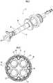
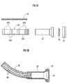
FIG. 1 is a perspective view showing a treatment-instrument insertion aid according to an embodiment of the present invention.FIG. 2 is a cross-sectional view taken along an A-A line ofFIG. 1 .FIG. 3A is an exploded side view of an outer tube, etc.FIG. 3B is a cross-sectional view of a bent outer tube, etc.FIG. 4A is an exploded view of an inner tube, etc.FIG. 4B is a perspective view of a bent inner tube ofFIG. 4A , etc.FIG. 5A is a side view of a guide member.FIG. 5B is a cross-sectional view taken along a B-B line ofFIG. 5A .FIG. 5C is a cross-sectional view taken along a C-C line ofFIG. 5A .- A treatment-
instrument insertion aid 10 according to an embodiment of the present invention will be described. The treatment-instrument insertion aid 10 is used to aid the insertion of a treatment instrument (not shown) such as an endoscope, forceps, a surgical knife or the like into a body. - As shown in
FIG.s 1 and 2 , the treatment-instrument insertion aid 10 mainly includesinner tubes 20, anouter tube 30 andrail members 40.Plural rail members 40 are fitted to theouter tube 30, and one or pluralinner tubes 20 are inserted in theouter tube 30. - The
outer tube 30 is a cylindrical body having flexibility, and hasplural guiding portions 31 which extend in the axial direction from a distal end side to a proximal end side on the inner surface. The guidingportions 31 are dovetail grooves formed on the inner wall surface of theouter tube 30, and formed at equal intervals in the circumferential direction on the inner wall surface. - In this embodiment, as shown in
FIG. 2 , the dovetail grooves are formed at protruding portions protruding to the center axis, and have rectangular cross-sectional shapes at an opening portion and a back side. However, the shape of the dovetail grooves is not limited to the foregoing shape, but may be a substantially trapezoidal shape which spreads further to the back side than the opening portion, or may be rectangular at the opening portion and substantially circular on the back side or the like. - The
outer tube 30 is composed ofsoft portions 30A andhard portions 30B alternately coupled to one another in the axial direction as shown inFIG.s 3A and 3B , thesoft portions 30A being formed of soft plastic such as polypropylene or vinyl chloride or a soft material such as rubber while thehard portions 30B are harder than thesoft portions 30A and formed of hard plastic such as ABS or polycarbonate or a hard material such as hard rubber. However, both the end portions in the axial direction of theouter tube 30 includehard portions 30B. Theouter tube 30 may be constructed to be partially or wholly transparent or translucent. - As shown in
FIG. 2 , afirst wire member 51 is embedded in the axial direction from the distal end side to the proximal end side on the peripheral wall portion of theouter tube 30. Thefirst wire member 51 further extends rearwards from the proximal end portion of theouter tube 30, and advance or retreat of thefirst wire member 51 is operated by a first wire member operating unit (not shown), whereby theouter tube 30 can be bent in the circumferential direction to turn the distal end portion of theouter tube 30 to a desired direction. - The shape of the
first wire member 51 may be temporarily fixed by temporarily locking the operation of the first wire member operating unit, for example by a ratchet mechanism, thereby maintaining the state where the distal end portion of theouter tube 30 is turned to the desired direction. - The
rail members 40 are formed of a hard material which is the same as or equivalent to the hard material of thehard portions 30B, for example, hard plastic such as ABS or polycarbonate or a hard material such as hard rubber, and constructed as elongated bodies having flexibility. Therail member 40 has a guidedportion 41 which extends in the axial direction from the distal end side to the proximal end side on the outer surface thereof. The guidedportion 41 is a protrusion formed on the outer surface of therail member 40. The guidedportion 41 may be intermittently formed. - In this embodiment, the protrusion is formed in such a shape engageable with the guiding
portion 31 of theouter tube 30, and the outside and neck portion thereof have rectangular cross-sectional shapes. However, the cross-sectional shape of the protrusion is not limited to the foregoing shapes, and may be a substantially trapezoidal shape spreading to the back side, or substantially circular at the outside thereof and rectangular at the neck portion. - The dovetail groove is formed by the inner peripheral surface of the
outer tube 30 and the right and left side surfaces of theadjacent rail members 40, and this dovetail groove constitutes an engagingportion 50. - In this embodiment, the dovetail groove has the rectangular cross-sectional view at both the opening portion and the back side as shown in
FIG. 2 . However, the cross-sectional shape of the dovetail groove may be a substantially trapezoidal shape which spreads further to the back side than the opening portion, or may be rectangular at the opening portion and substantially circular on the back side or the like. - As shown in
FIG.s 3A and 3B , the distal end portions of therail members 40 are fixed to thehard portion 30B nearest to the distal end side of theouter tube 30 by adhesive agent or the like while the guidedportions 41 are engaged with the guidingportions 31, but the other portions of therail members 40 are not fixed to theouter tube 30. As a result, when theouter tube 30 is bent, therespective rail members 40 bend while following the bending of theouter tube 30, and thus therail members 40 do not hinder the bending of theouter tube 30. Accordingly, theouter tube 30 can be bent while maintaining the cross-sectional shape. - Furthermore, a
guide pipe 32, an airleakage preventing ring 33, ad avalve sheet 34 are fitted to the proximal end side of theouter tube 30. - The
guide pipe 32 is a member for connecting theouter tube 30 and the airleakage preventing ring 33, and formed of metal such as stainless steel or the like, or a hard material such as resin. The airleakage preventing ring 33 is adhesively fixed to thevalve sheet 34. The air leakage preventing ring is detachably fitted to theguide pipe 32. Plural holes through which theinner tubes 20 are inserted are formed in thevalve sheet 34. - As shown in
FIG. 2 , theinner tube 20 is a cylindrical body having flexibility, and a treatment instrument such as an endoscope, forceps or a surgical knife is insertable into theinner tube 20. Theinner tube 20 may have one channel for inserting the treatment instrument or two or more channels. The outer peripheral surface of theinner tube 20 may be subjected to a hydrophilic treatment. According to hand manipulation, eachinner tube 20 can be inserted into and removed from theouter tube 30 whose inner peripheral surface is engaged with therail members 40. - In this embodiment, the
inner tubes 20 have the same outer diameter, but theinner tubes 20 having different outer diameters may be used. - As shown in
FIG.s 4A and4B , theinner tube 20 is composed ofsoft portions 20A andhard portions 20B coupled to one another in the axial direction, thesoft portions 20A being formed of soft plastic such as polypropylene or vinyl chloride or a soft material such as rubber while thehard portions 20B are harder than thesoft portions 20A and formed of hard plastic such as ABS or polycarbonate or a hard material such as hard rubber. Both the end portions in the axial direction of theinner tube 20 includehard portions 20B, and an intermediate portion between thesehard portions 20B includes asoft portion 20A. - Referring also to
FIG. 2 , theinner tube 20 has an engagedportion 21 which is slidably engageable with an engagingportion 50 from the distal end to the proximal end of the outer peripheral surface of theinner tube 20, and a scale (not shown) for grasping the insertion depth. - In this embodiment, the engaged
portion 21 is a rectangular wide protrusion protruding to the outer peripheral surface of theinner tube 20, but it has any shape insofar as it is engageable with the engagingportion 50. - The engaged
portion 21 is continuously provided from the distal end to the proximal end of theinner tube 20. However, the engagedportion 21 may be intermittently provided at a part of the portion between the distal end and the proximal end of the outer peripheral surface of theinner tube 20, and may be provided at least only at the distal end. - A
second wire member 52 is embedded in the axial direction from the distal end side to the proximal end side in the engagedportion 21 of theinner tube 20. Thesecond wire member 52 further extends rearwards from the proximal end portion of theinner tube 20, and advance and retreat thereof can be performed by a slide knob 25 (an operating unit for the second wire member). Thesecond wire member 52 may be merely fixed to theinner tube 20, and it may be embedded on the peripheral wall portion of theinner tube 20 instead of being embedded in the engagedportion 21, or adhesively fixed to the outer peripheral surface of theinner tube 20. - A bendable swing pipe (corresponding to a bending member of the present invention) 22 and a nose cover 23 (corresponding to a cover of the present invention, and see
FIG.s 4A and4B ) are fitted to the distal end portion of theinner tube 20. - The
swing pipe 22 is formed of a hard material whose hardness is equal to or harder than that of thehard portion 20A of theinner tube 20, for example, metal such as stainless steel or the like.Plural slits 22a extending in the axial direction are formed in theswing pipe 22. In this embodiment, a thin wall part(s) may be formed in place of formation of theslits 22a. As a result, theswing pipe 22 is easily bendable only in a specific direction. Thesecond wire member 52 passes outside the swing pipe. - The
nose cover 23 is fixed to the distal end portion of theswing pipe 22. Thenose cover 23 is formed of a soft material softer than the hard material constituting theswing pipe 22, for example, soft plastic such as vinyl chloride, rubber or the like. Since thenose cover 23 is formed of the soft material, thenose cover 23 does not damage tissues even when it comes into contact with the tissues. The distal end portion of thesecond wire member 52 is fixed to thenose cover 23. - On the other hand, a
first slide pipe 24, aslide knob 25, aslide stopper 26, asecond slide pipe 27 and adeaeration preventing valve 28 are fitted to the proximal end portion of theinner tube 20. - The
first slide pipe 24 is connected to the rear end portion of theinner tube 20, and inserted in the air leakage preventing ring 33 (seeFIG.s 3A and 3B ). As a result, air in a body cavity can be prevented from leaking from places where theinner tubes 20 of theouter tube 30 are not inserted, or from the outer peripheral portions of the insertedinner tubes 20. - The distal end side of the
first slide pipe 24 includes ahard portion 24A formed of a hard material whose hardness is equal or equivalent to the hardness of thehard portion 20B of theinner tube 20, and the rear end side of thefirst slide pipe 24 includes asemi-hard portion 24B formed of a semi-hard material such as elastomer, polyurethane or the like whose hardness is softer than thehard portion 20B of theinner tube 20 and harder than thesoft portion 20A. When the pluralinner tubes 20 are inserted into theouter tube 30, thesemi-hard portions 24B can prevent the interference among theinner tubes 20. - The rear end portion of the
second wire member 52 is fixed to theslide knob 25. Theslide knob 25 is constructed to be freely slidable with respect to thesecond slide pipe 27, and can be locked at a desired position with respect to thesecond slide pipe 27 by theslide stopper 26. - The
deaeration preventing valve 28 can prevent occurrence of air leakage from a body cavity, for example, an abdominal cavity from theinner tubes 20 in which no treatment instrument is inserted. Thedeaeration preventing valve 28 is freely detachably fitted to the rear end of thesecond slide pipe 27. - When the distal end portion of the
inner tube 20 protrudes from the distal end of theouter tube 30, thesecond wire member 52 bends theswing pipe 22 to turn the distal end portion of theswing pipe 22 to a desired direction. When the distal end portion of theinner tube 20 does not protrude from the distal end of theouter tube 30 and theinner tube 20 is accommodated in theouter tube 30, thesecond wire member 52 can bend theouter tube 30 while following bending of theinner tube 20. - The shape of the
second wire member 52 may be temporarily fixed by temporarily locking the operation of theslide knob 25, for example by a ratchet mechanism, thereby maintaining the state where the distal end portion of theinner tube 20 or theouter tube 30 is turned to a desired direction. Engaged portions 61 ofguide members 60 are engaged with the engagingportions 50 with which the engagedportions 21 of theinner tubes 20 are not engaged.- As shown in
FIG.s 5A to 5C , theguide member 60 is an elongated member including a distalend side portion 60A at which the engagedportion 61 to be engaged with the engagingportion 50 is formed inside, and a proximalend side portion 60B. The distalend side portion 60A is formed of a semi-hard material such as elastomer, polyurethane, a wire or a copper wire which is softer than thehard portion 20B of theinner tube 20 and harder than thesoft portion 20A. The proximalend side portion 60B is formed of a hard material whose hardness is equal or equivalent to thehard portion 20B of theinner tube 20. - In this embodiment, the engaged
portion 61 is a rectangular wide protrusion protruding to the outer peripheral surface of theinner tube 20, but it may have any shape insofar as it is engageable with the engagingportion 50. The main body portion 62 of the distalend side portion 60A has a toroidal cross-section. The proximalend side portion 60B has a substantially triangular cross-section having a circular hole at an apex thereof. - According to the treatment-
instrument insertion aid 10 of this embodiment, the engagedportions 21 of theinner tubes 20 are slid while engaged with the guidingportions 31 extending in the axial direction from the distal end side to the proximal end side, whereby theinner tubes 20 can be smoothly inserted and pulled out while maintaining the positions of theinner tubes 20 in theouter tube 30, and a desired treatment instrument can be used. - As described above, according to the treatment-
instrument insertion aid 10 of this embodiment, since both the end portions of theinner tube 20 include thehard portions 20B, theinner tube 20 can be prevented from being crushed at both the end portions thereof. Furthermore, since the intermediate portion of theinner tube 20 includes the easily bendablesoft portion 20A, the inner tube can be easily bent during hand manipulation. - Since the
swing pipe 22 is fitted to the distal end portion of theinner tube 20, the treatment instrument can be easily turned to a desired direction. - Furthermore, since the
nose cover 23 formed of the soft material is fitted to the distal end portion of theswing pipe 22, a risk of damaging tissues can be prevented. - Since both the end portions of the
outer tube 30 include thehard portions 30B, theouter tube 30 can be prevented from being crushed at least at both the end portions, and further theinner tubes 20 of theouter tube 30 can be prevented from being crushed. Since theouter tube 30 has the easily bendablesoft portions 30A, theouter tube 30 can be easily bent during hand manipulation. - In addition, since the
hard portion 30B also exists at the intermediate portion, theouter tube 30 can be also prevented from being crushed at this portion. Furthermore, theinner tubes 20 in theouter tube 30 can be more effectively prevented from being crushed. - Furthermore, since the
inner tubes 20 can be locked at predetermined places by using therail members 40 locked on the inner peripheral surface of theouter tube 30, the interference among theinner tubes 20 can be prevented. - Since the
guide members 60 are engaged with the engagingportions 50 with which noinner tube 20 is engaged, the interference among theinner tubes 20 can be surely prevented by theguide members 60. - The embodiment of the present invention has been described above. However, the present invention is not limited to the above embodiment, and the configuration and form of the assembled device may be appropriately modified.
- For example, in the foregoing description, the
plural rail members 40 are engaged with the inner peripheral surface of theouter tube 30 to configure the engagingportions 50. However, the present invention is not limited to this configuration, and theouter tube 30 and theplural rail members 40 may be integrated with each other to configure the engagingportions 50. Furthermore, the soft material, the hard material and the semi-hard material may be materials obtained by changing the blending of the same kind of resin to adjust softness and hardness. - 10 ... treatment-instrument insertion aid, 20 ... inner tube, 20A ... soft portion (intermediate portion), 20B ... hard portion (both end portions), 21 ... engaged portion, 22 ... swing pipe (bending member), 22a ... slit, 23 ... nose cover (cover), 30 ... outer tube, 30A ... soft portion, 30B ... hard portion, 31 ... guiding portion, 40 ... rail member, 41 ... guided portion, 50 ... engaging portion, 51 ... first wire member, 52 ... second wire member, 60 ... guide member, 61 ... engaged portion
Claims (8)
- A treatment-instrument insertion aid (10) for aiding insertion of a treatment instrument into a body, comprising:an inner tube (20) having flexibility into which the treatment instrument is insertable; andan outer tube (30) having flexibility into which the inner tube is insertable,wherein both end portions of the inner tube are formed of a hard material (20B), and an intermediate portion between the both end portions is formed of a soft material (20A) softer than the hard material,characterized in that: a bendable bending member (22) having a cylindrical shape is attached to a distal end portion of the inner tube,and wherein the bending member is formed of a hard material same as or harder than the hard material, and partially has a thin wall part which is reduced in thickness.
- The treatment-instrument insertion aid according to claim 1, wherein a cover (23) formed of a soft material softer than the hard material constituting the bending member is attached to a distal end portion of the bending member.
- The treatment-instrument insertion aid according to claim 1, wherein both end portions of the outer tube are formed of a hard material (30B), and an intermediate portion between the both end portions has a portion formed of a soft material (30A) softer than the hard material.
- The treatment-instrument insertion aid according to claim 3, wherein the intermediate portion has alternately a portion formed of the soft material and a portion formed of a hard material harder than the soft material.
- The treatment-instrument insertion aid according to claim 1, wherein an engaging portion (50) is provided on an inner peripheral surface of the outer tube, and an engaged portion (21) to be engaged with the engaging portion is provided on an outer peripheral surface of the inner tube.
- The treatment-instrument insertion aid according to claim 5, wherein an engaged portion of a guide member extending in an axial direction from a distal end side to a proximal end side is engaged with the engaging portion with which the engaged portion of the inner tube is not engaged, wherein the guide member prevents the interference among the inner tubes.
- The treatment-instrument insertion aid according to claim 1, wherein a plurality of engaging portions are circumferentially spaced apart from one another on an inner peripheral surface of the outer tube,
engaged portions of rail members each extending in an axial direction from a distal end side to a proximal end side are engaged with the plurality of engaging portions, and
an engaged portion to be engaged with an engaging portion formed as a dovetail groove between the inner peripheral surface of the outer tube and the adjacent rail members is provided on an outer peripheral surface of the inner tube. - The treatment-instrument insertion aid according to claim 7, wherein an engaged portion of a guide member extending in the axial direction from the distal end side to the proximal end side is engaged with the engaging portion with which the engaged portion of the inner tube is not engaged.
Applications Claiming Priority (1)
| Application Number | Priority Date | Filing Date | Title |
|---|---|---|---|
| PCT/JP2015/057388WO2016143142A1 (en) | 2015-03-12 | 2015-03-12 | Treatment-instrument insertion aid |
Publications (3)
| Publication Number | Publication Date |
|---|---|
| EP3269288A1 EP3269288A1 (en) | 2018-01-17 |
| EP3269288A4 EP3269288A4 (en) | 2018-11-14 |
| EP3269288B1true EP3269288B1 (en) | 2020-06-03 |
Family
ID=56878603
Family Applications (1)
| Application Number | Title | Priority Date | Filing Date |
|---|---|---|---|
| EP15884629.5AActiveEP3269288B1 (en) | 2015-03-12 | 2015-03-12 | Treatment-instrument insertion aid |
Country Status (7)
| Country | Link |
|---|---|
| US (1) | US11272833B2 (en) |
| EP (1) | EP3269288B1 (en) |
| JP (1) | JP6623462B2 (en) |
| MY (1) | MY195396A (en) |
| SG (1) | SG11201707256VA (en) |
| TW (1) | TWI652035B (en) |
| WO (1) | WO2016143142A1 (en) |
Families Citing this family (7)
| Publication number | Priority date | Publication date | Assignee | Title |
|---|---|---|---|---|
| MY195396A (en)* | 2015-03-12 | 2023-01-18 | Univ Keio | Treatment-instrument insertion aid |
| JP6712646B2 (en)* | 2016-10-14 | 2020-06-24 | 株式会社メディカロイド | Medical instruments and surgical systems |
| US20180192855A1 (en)* | 2017-01-12 | 2018-07-12 | Olympus Corporation | Insertion assist system and insertion instrument |
| TWI728116B (en)* | 2017-05-31 | 2021-05-21 | 學校法人慶應義塾 | Medical inner tube |
| WO2018220767A1 (en)* | 2017-05-31 | 2018-12-06 | 学校法人慶應義塾 | Inner tube |
| JP7093911B2 (en)* | 2018-06-04 | 2022-07-01 | 慶應義塾 | Inner tube |
| WO2024229428A1 (en)* | 2023-05-04 | 2024-11-07 | Boston Scientific Scimed, Inc. | Devices, systems, and methods for articulation and/or retroflexion of a medical device |
Family Cites Families (35)
| Publication number | Priority date | Publication date | Assignee | Title |
|---|---|---|---|---|
| JPS5689233A (en)* | 1979-12-24 | 1981-07-20 | Olympus Optical Co | Endoscope |
| JP2602212B2 (en) | 1985-09-30 | 1997-04-23 | オリンパス光学工業株式会社 | Multi-lumen tube endoscope |
| JPH01254138A (en) | 1988-04-01 | 1989-10-11 | Fuji Photo Optical Co Ltd | Soft part of endoscope |
| JP3543027B2 (en)* | 1995-04-10 | 2004-07-14 | オリンパス株式会社 | Curved sheath for probe |
| JP4053147B2 (en) | 1998-07-22 | 2008-02-27 | オリンパス株式会社 | Endoscopic treatment device |
| JP4242491B2 (en) | 1998-12-09 | 2009-03-25 | オリンパス株式会社 | Endoscopic treatment device |
| DE19906191A1 (en)* | 1999-02-15 | 2000-08-17 | Ingo F Herrmann | Mouldable endoscope for transmitting light and images with supplementary device has non-round cross section along longitudinal section for inserting in human or animal body opening |
| JP4503725B2 (en)* | 1999-05-17 | 2010-07-14 | オリンパス株式会社 | Endoscopic treatment device |
| US6398791B1 (en) | 1999-06-11 | 2002-06-04 | Scimed Life Systems Inc | Variable composite sheath with interrupted sections |
| US7744613B2 (en)* | 1999-06-25 | 2010-06-29 | Usgi Medical, Inc. | Apparatus and methods for forming and securing gastrointestinal tissue folds |
| JP3927764B2 (en)* | 2000-09-01 | 2007-06-13 | ペンタックス株式会社 | Endoscope flexible tube |
| US7815565B2 (en)* | 2003-05-16 | 2010-10-19 | Ethicon Endo-Surgery, Inc. | Endcap for use with an endoscope |
| US7431694B2 (en) | 2003-05-16 | 2008-10-07 | Ethicon Endo-Surgery, Inc. | Method of guiding medical devices |
| JP4500015B2 (en)* | 2003-07-31 | 2010-07-14 | オリンパス株式会社 | Endoscope overtube |
| JP2005177517A (en) | 2005-02-10 | 2005-07-07 | Olympus Corp | Endoscope |
| US20070106113A1 (en)* | 2005-11-07 | 2007-05-10 | Biagio Ravo | Combination endoscopic operative delivery system |
| ITMI20060411A1 (en)* | 2006-03-07 | 2007-09-08 | Ethicon Endo Surgery Inc | METHOD TO RECYCLING BY ENDOLUMINAL OR LAPAROSCOPIC A SAMPLE OF FABRIC FROM A ZONE IN THE BODY OF A PATIENT MEANS OF TRACTION AND KIT |
| US7803137B2 (en)* | 2006-03-22 | 2010-09-28 | Ethicon Endo-Surgery, Inc. | Intubation system for use with an endoscope |
| US7976458B2 (en)* | 2006-12-05 | 2011-07-12 | Ethicon Endo-Surgery, Inc. | Independent articulating accessory channel |
| US8007432B2 (en)* | 2007-01-26 | 2011-08-30 | Ethicon Endo-Surgery, Inc. | Endoscopic accessory control mechanism |
| US9254077B2 (en)* | 2007-04-02 | 2016-02-09 | Cook Medical Technologies Llc | Endoscopic apparatus having an outer rail |
| US9066655B2 (en)* | 2007-12-07 | 2015-06-30 | Ethicon Endo-Surgery, Inc. | Selective stiffening devices and methods |
| US8287469B2 (en)* | 2008-01-09 | 2012-10-16 | Ethicon Endo-Surgery, Inc. | Articulating surgical device and method of use |
| US20090259141A1 (en)* | 2008-03-21 | 2009-10-15 | Usgi Medical, Inc. | Steerable tool guide for use with flexible endoscopic medical devices |
| WO2010009292A1 (en)* | 2008-07-18 | 2010-01-21 | Boston Scientific Scimed, Inc. | Endoscope with guide |
| JP5580540B2 (en)* | 2009-03-02 | 2014-08-27 | オリンパス株式会社 | Guide device |
| US8491585B2 (en)* | 2009-05-06 | 2013-07-23 | Kambiz Hannani | Methods and systems for minimally invasive lateral decompression |
| HU229773B1 (en)* | 2009-09-02 | 2014-06-30 | A tool for surgical intervention | |
| CN102413863A (en)* | 2009-10-14 | 2012-04-11 | 奥林巴斯医疗株式会社 | Flexible medical tube and insertion part of medical instrument |
| JP5498422B2 (en)* | 2011-03-28 | 2014-05-21 | 富士フイルム株式会社 | Endoscope insertion aid |
| CN103930044B (en)* | 2012-03-08 | 2016-05-18 | 奥林巴斯株式会社 | guide sheath and medical system |
| SG11201502034WA (en) | 2012-09-19 | 2015-05-28 | Univ Nanyang Tech | Flexible master - slave robotic endoscopy system |
| US20160174814A1 (en)* | 2013-08-31 | 2016-06-23 | Morena Medical Applications Ltd. | Endoscope with shared working channel |
| WO2015029040A1 (en)* | 2013-08-31 | 2015-03-05 | Morena Medical Applications Ltd. | Endoscope with shared working channel |
| MY195396A (en)* | 2015-03-12 | 2023-01-18 | Univ Keio | Treatment-instrument insertion aid |
- 2015
- 2015-03-12MYMYPI2017703342Apatent/MY195396A/enunknown
- 2015-03-12SGSG11201707256VApatent/SG11201707256VA/enunknown
- 2015-03-12USUS15/556,670patent/US11272833B2/enactiveActive
- 2015-03-12WOPCT/JP2015/057388patent/WO2016143142A1/ennot_activeCeased
- 2015-03-12EPEP15884629.5Apatent/EP3269288B1/enactiveActive
- 2015-03-12JPJP2017504543Apatent/JP6623462B2/enactiveActive
- 2015-03-13TWTW104108265Apatent/TWI652035B/enactive
Non-Patent Citations (1)
| Title |
|---|
| None* |
Also Published As
| Publication number | Publication date |
|---|---|
| TW201632134A (en) | 2016-09-16 |
| MY195396A (en) | 2023-01-18 |
| EP3269288A4 (en) | 2018-11-14 |
| JPWO2016143142A1 (en) | 2017-12-21 |
| WO2016143142A1 (en) | 2016-09-15 |
| US20180049624A1 (en) | 2018-02-22 |
| SG11201707256VA (en) | 2017-10-30 |
| TWI652035B (en) | 2019-03-01 |
| US11272833B2 (en) | 2022-03-15 |
| EP3269288A1 (en) | 2018-01-17 |
| JP6623462B2 (en) | 2019-12-25 |
Similar Documents
| Publication | Publication Date | Title |
|---|---|---|
| EP3269288B1 (en) | Treatment-instrument insertion aid | |
| US20090062606A1 (en) | Endoscope guiding tube device | |
| JP2005131211A (en) | Externally mounted channel for endoscope | |
| EP2574269B1 (en) | Insertion portion rigidity changeable catheter with balloon | |
| JP2007268270A (en) | Endscope ancillary attaching device | |
| EP3095389B1 (en) | Surgical tool insertion aid | |
| US20170172385A1 (en) | Endoscope | |
| WO2015083644A1 (en) | Passive bending section for endoscope and endoscope | |
| US20210121162A1 (en) | Medical apparatus with segmented bendable sections | |
| US20140114126A1 (en) | Universal endoscope attachment system and related methods of use | |
| JP2009112537A (en) | Flexible endoscope | |
| JP2009056056A (en) | Endoscope guiding tube device | |
| JP2009056054A (en) | Endoscope guiding tube device | |
| EP3269289B1 (en) | Treatment-instrument insertion aid | |
| TW201733517A (en) | Endoscope treatment device | |
| JP7464923B2 (en) | Treatment tool insertion aid | |
| WO2010009070A1 (en) | Endoscopic translumenal articulatable and steerable flexible overtube | |
| EP3490428B1 (en) | Steerable catheter handle | |
| JP5570370B2 (en) | Surgical endoscope device | |
| JP6504424B1 (en) | Medical devices and systems | |
| JP2009089724A (en) | Separate type endoscope | |
| WO2019130650A1 (en) | Medical device and medical system | |
| WO2017195348A1 (en) | Medical overtube |
Legal Events
| Date | Code | Title | Description |
|---|---|---|---|
| STAA | Information on the status of an ep patent application or granted ep patent | Free format text:STATUS: THE INTERNATIONAL PUBLICATION HAS BEEN MADE | |
| PUAI | Public reference made under article 153(3) epc to a published international application that has entered the european phase | Free format text:ORIGINAL CODE: 0009012 | |
| STAA | Information on the status of an ep patent application or granted ep patent | Free format text:STATUS: REQUEST FOR EXAMINATION WAS MADE | |
| 17P | Request for examination filed | Effective date:20170918 | |
| AK | Designated contracting states | Kind code of ref document:A1 Designated state(s):AL AT BE BG CH CY CZ DE DK EE ES FI FR GB GR HR HU IE IS IT LI LT LU LV MC MK MT NL NO PL PT RO RS SE SI SK SM TR | |
| AX | Request for extension of the european patent | Extension state:BA ME | |
| DAV | Request for validation of the european patent (deleted) | ||
| DAX | Request for extension of the european patent (deleted) | ||
| A4 | Supplementary search report drawn up and despatched | Effective date:20181015 | |
| RIC1 | Information provided on ipc code assigned before grant | Ipc:A61B 1/005 20060101ALI20181008BHEP Ipc:A61B 1/018 20060101ALI20181008BHEP Ipc:A61B 1/00 20060101AFI20181008BHEP Ipc:A61B 1/01 20060101ALI20181008BHEP | |
| GRAP | Despatch of communication of intention to grant a patent | Free format text:ORIGINAL CODE: EPIDOSNIGR1 | |
| STAA | Information on the status of an ep patent application or granted ep patent | Free format text:STATUS: GRANT OF PATENT IS INTENDED | |
| INTG | Intention to grant announced | Effective date:20200107 | |
| GRAS | Grant fee paid | Free format text:ORIGINAL CODE: EPIDOSNIGR3 | |
| GRAA | (expected) grant | Free format text:ORIGINAL CODE: 0009210 | |
| STAA | Information on the status of an ep patent application or granted ep patent | Free format text:STATUS: THE PATENT HAS BEEN GRANTED | |
| AK | Designated contracting states | Kind code of ref document:B1 Designated state(s):AL AT BE BG CH CY CZ DE DK EE ES FI FR GB GR HR HU IE IS IT LI LT LU LV MC MK MT NL NO PL PT RO RS SE SI SK SM TR | |
| REG | Reference to a national code | Ref country code:GB Ref legal event code:FG4D | |
| REG | Reference to a national code | Ref country code:CH Ref legal event code:EP Ref country code:AT Ref legal event code:REF Ref document number:1276126 Country of ref document:AT Kind code of ref document:T Effective date:20200615 | |
| REG | Reference to a national code | Ref country code:DE Ref legal event code:R096 Ref document number:602015053935 Country of ref document:DE | |
| REG | Reference to a national code | Ref country code:LT Ref legal event code:MG4D | |
| PG25 | Lapsed in a contracting state [announced via postgrant information from national office to epo] | Ref country code:LT Free format text:LAPSE BECAUSE OF FAILURE TO SUBMIT A TRANSLATION OF THE DESCRIPTION OR TO PAY THE FEE WITHIN THE PRESCRIBED TIME-LIMIT Effective date:20200603 Ref country code:NO Free format text:LAPSE BECAUSE OF FAILURE TO SUBMIT A TRANSLATION OF THE DESCRIPTION OR TO PAY THE FEE WITHIN THE PRESCRIBED TIME-LIMIT Effective date:20200903 Ref country code:GR Free format text:LAPSE BECAUSE OF FAILURE TO SUBMIT A TRANSLATION OF THE DESCRIPTION OR TO PAY THE FEE WITHIN THE PRESCRIBED TIME-LIMIT Effective date:20200904 Ref country code:FI Free format text:LAPSE BECAUSE OF FAILURE TO SUBMIT A TRANSLATION OF THE DESCRIPTION OR TO PAY THE FEE WITHIN THE PRESCRIBED TIME-LIMIT Effective date:20200603 Ref country code:SE Free format text:LAPSE BECAUSE OF FAILURE TO SUBMIT A TRANSLATION OF THE DESCRIPTION OR TO PAY THE FEE WITHIN THE PRESCRIBED TIME-LIMIT Effective date:20200603 | |
| REG | Reference to a national code | Ref country code:NL Ref legal event code:MP Effective date:20200603 | |
| PG25 | Lapsed in a contracting state [announced via postgrant information from national office to epo] | Ref country code:RS Free format text:LAPSE BECAUSE OF FAILURE TO SUBMIT A TRANSLATION OF THE DESCRIPTION OR TO PAY THE FEE WITHIN THE PRESCRIBED TIME-LIMIT Effective date:20200603 Ref country code:HR Free format text:LAPSE BECAUSE OF FAILURE TO SUBMIT A TRANSLATION OF THE DESCRIPTION OR TO PAY THE FEE WITHIN THE PRESCRIBED TIME-LIMIT Effective date:20200603 Ref country code:LV Free format text:LAPSE BECAUSE OF FAILURE TO SUBMIT A TRANSLATION OF THE DESCRIPTION OR TO PAY THE FEE WITHIN THE PRESCRIBED TIME-LIMIT Effective date:20200603 Ref country code:BG Free format text:LAPSE BECAUSE OF FAILURE TO SUBMIT A TRANSLATION OF THE DESCRIPTION OR TO PAY THE FEE WITHIN THE PRESCRIBED TIME-LIMIT Effective date:20200903 | |
| REG | Reference to a national code | Ref country code:AT Ref legal event code:MK05 Ref document number:1276126 Country of ref document:AT Kind code of ref document:T Effective date:20200603 | |
| PG25 | Lapsed in a contracting state [announced via postgrant information from national office to epo] | Ref country code:AL Free format text:LAPSE BECAUSE OF FAILURE TO SUBMIT A TRANSLATION OF THE DESCRIPTION OR TO PAY THE FEE WITHIN THE PRESCRIBED TIME-LIMIT Effective date:20200603 Ref country code:NL Free format text:LAPSE BECAUSE OF FAILURE TO SUBMIT A TRANSLATION OF THE DESCRIPTION OR TO PAY THE FEE WITHIN THE PRESCRIBED TIME-LIMIT Effective date:20200603 | |
| PG25 | Lapsed in a contracting state [announced via postgrant information from national office to epo] | Ref country code:SM Free format text:LAPSE BECAUSE OF FAILURE TO SUBMIT A TRANSLATION OF THE DESCRIPTION OR TO PAY THE FEE WITHIN THE PRESCRIBED TIME-LIMIT Effective date:20200603 Ref country code:EE Free format text:LAPSE BECAUSE OF FAILURE TO SUBMIT A TRANSLATION OF THE DESCRIPTION OR TO PAY THE FEE WITHIN THE PRESCRIBED TIME-LIMIT Effective date:20200603 Ref country code:RO Free format text:LAPSE BECAUSE OF FAILURE TO SUBMIT A TRANSLATION OF THE DESCRIPTION OR TO PAY THE FEE WITHIN THE PRESCRIBED TIME-LIMIT Effective date:20200603 Ref country code:ES Free format text:LAPSE BECAUSE OF FAILURE TO SUBMIT A TRANSLATION OF THE DESCRIPTION OR TO PAY THE FEE WITHIN THE PRESCRIBED TIME-LIMIT Effective date:20200603 Ref country code:CZ Free format text:LAPSE BECAUSE OF FAILURE TO SUBMIT A TRANSLATION OF THE DESCRIPTION OR TO PAY THE FEE WITHIN THE PRESCRIBED TIME-LIMIT Effective date:20200603 Ref country code:AT Free format text:LAPSE BECAUSE OF FAILURE TO SUBMIT A TRANSLATION OF THE DESCRIPTION OR TO PAY THE FEE WITHIN THE PRESCRIBED TIME-LIMIT Effective date:20200603 Ref country code:IT Free format text:LAPSE BECAUSE OF FAILURE TO SUBMIT A TRANSLATION OF THE DESCRIPTION OR TO PAY THE FEE WITHIN THE PRESCRIBED TIME-LIMIT Effective date:20200603 Ref country code:PT Free format text:LAPSE BECAUSE OF FAILURE TO SUBMIT A TRANSLATION OF THE DESCRIPTION OR TO PAY THE FEE WITHIN THE PRESCRIBED TIME-LIMIT Effective date:20201006 | |
| PG25 | Lapsed in a contracting state [announced via postgrant information from national office to epo] | Ref country code:PL Free format text:LAPSE BECAUSE OF FAILURE TO SUBMIT A TRANSLATION OF THE DESCRIPTION OR TO PAY THE FEE WITHIN THE PRESCRIBED TIME-LIMIT Effective date:20200603 Ref country code:SK Free format text:LAPSE BECAUSE OF FAILURE TO SUBMIT A TRANSLATION OF THE DESCRIPTION OR TO PAY THE FEE WITHIN THE PRESCRIBED TIME-LIMIT Effective date:20200603 Ref country code:IS Free format text:LAPSE BECAUSE OF FAILURE TO SUBMIT A TRANSLATION OF THE DESCRIPTION OR TO PAY THE FEE WITHIN THE PRESCRIBED TIME-LIMIT Effective date:20201003 | |
| REG | Reference to a national code | Ref country code:DE Ref legal event code:R097 Ref document number:602015053935 Country of ref document:DE | |
| PLBE | No opposition filed within time limit | Free format text:ORIGINAL CODE: 0009261 | |
| STAA | Information on the status of an ep patent application or granted ep patent | Free format text:STATUS: NO OPPOSITION FILED WITHIN TIME LIMIT | |
| PG25 | Lapsed in a contracting state [announced via postgrant information from national office to epo] | Ref country code:DK Free format text:LAPSE BECAUSE OF FAILURE TO SUBMIT A TRANSLATION OF THE DESCRIPTION OR TO PAY THE FEE WITHIN THE PRESCRIBED TIME-LIMIT Effective date:20200603 | |
| 26N | No opposition filed | Effective date:20210304 | |
| PG25 | Lapsed in a contracting state [announced via postgrant information from national office to epo] | Ref country code:SI Free format text:LAPSE BECAUSE OF FAILURE TO SUBMIT A TRANSLATION OF THE DESCRIPTION OR TO PAY THE FEE WITHIN THE PRESCRIBED TIME-LIMIT Effective date:20200603 | |
| PG25 | Lapsed in a contracting state [announced via postgrant information from national office to epo] | Ref country code:MC Free format text:LAPSE BECAUSE OF FAILURE TO SUBMIT A TRANSLATION OF THE DESCRIPTION OR TO PAY THE FEE WITHIN THE PRESCRIBED TIME-LIMIT Effective date:20200603 | |
| REG | Reference to a national code | Ref country code:CH Ref legal event code:PL | |
| GBPC | Gb: european patent ceased through non-payment of renewal fee | Effective date:20210312 | |
| REG | Reference to a national code | Ref country code:BE Ref legal event code:MM Effective date:20210331 | |
| PG25 | Lapsed in a contracting state [announced via postgrant information from national office to epo] | Ref country code:CH Free format text:LAPSE BECAUSE OF NON-PAYMENT OF DUE FEES Effective date:20210331 Ref country code:LI Free format text:LAPSE BECAUSE OF NON-PAYMENT OF DUE FEES Effective date:20210331 Ref country code:LU Free format text:LAPSE BECAUSE OF NON-PAYMENT OF DUE FEES Effective date:20210312 Ref country code:GB Free format text:LAPSE BECAUSE OF NON-PAYMENT OF DUE FEES Effective date:20210312 Ref country code:IE Free format text:LAPSE BECAUSE OF NON-PAYMENT OF DUE FEES Effective date:20210312 | |
| PG25 | Lapsed in a contracting state [announced via postgrant information from national office to epo] | Ref country code:BE Free format text:LAPSE BECAUSE OF NON-PAYMENT OF DUE FEES Effective date:20210331 | |
| PG25 | Lapsed in a contracting state [announced via postgrant information from national office to epo] | Ref country code:CY Free format text:LAPSE BECAUSE OF FAILURE TO SUBMIT A TRANSLATION OF THE DESCRIPTION OR TO PAY THE FEE WITHIN THE PRESCRIBED TIME-LIMIT Effective date:20200603 | |
| PG25 | Lapsed in a contracting state [announced via postgrant information from national office to epo] | Ref country code:HU Free format text:LAPSE BECAUSE OF FAILURE TO SUBMIT A TRANSLATION OF THE DESCRIPTION OR TO PAY THE FEE WITHIN THE PRESCRIBED TIME-LIMIT; INVALID AB INITIO Effective date:20150312 | |
| PG25 | Lapsed in a contracting state [announced via postgrant information from national office to epo] | Ref country code:MK Free format text:LAPSE BECAUSE OF FAILURE TO SUBMIT A TRANSLATION OF THE DESCRIPTION OR TO PAY THE FEE WITHIN THE PRESCRIBED TIME-LIMIT Effective date:20200603 | |
| PG25 | Lapsed in a contracting state [announced via postgrant information from national office to epo] | Ref country code:MT Free format text:LAPSE BECAUSE OF FAILURE TO SUBMIT A TRANSLATION OF THE DESCRIPTION OR TO PAY THE FEE WITHIN THE PRESCRIBED TIME-LIMIT Effective date:20200603 | |
| PGFP | Annual fee paid to national office [announced via postgrant information from national office to epo] | Ref country code:DE Payment date:20250319 Year of fee payment:11 | |
| PGFP | Annual fee paid to national office [announced via postgrant information from national office to epo] | Ref country code:FR Payment date:20250325 Year of fee payment:11 |