EP3267283A1 - Holder apparatus for a portable electronic device - Google Patents
Holder apparatus for a portable electronic deviceDownload PDFInfo
- Publication number
- EP3267283A1 EP3267283A1EP16178161.2AEP16178161AEP3267283A1EP 3267283 A1EP3267283 A1EP 3267283A1EP 16178161 AEP16178161 AEP 16178161AEP 3267283 A1EP3267283 A1EP 3267283A1
- Authority
- EP
- European Patent Office
- Prior art keywords
- electronic device
- portable electronic
- rear wall
- receiving device
- switching means
- Prior art date
- Legal status (The legal status is an assumption and is not a legal conclusion. Google has not performed a legal analysis and makes no representation as to the accuracy of the status listed.)
- Granted
Links
Images


Classifications
- G—PHYSICS
- G06—COMPUTING OR CALCULATING; COUNTING
- G06F—ELECTRIC DIGITAL DATA PROCESSING
- G06F1/00—Details not covered by groups G06F3/00 - G06F13/00 and G06F21/00
- G06F1/16—Constructional details or arrangements
- G06F1/1613—Constructional details or arrangements for portable computers
- G06F1/1626—Constructional details or arrangements for portable computers with a single-body enclosure integrating a flat display, e.g. Personal Digital Assistants [PDAs]
- G—PHYSICS
- G06—COMPUTING OR CALCULATING; COUNTING
- G06F—ELECTRIC DIGITAL DATA PROCESSING
- G06F1/00—Details not covered by groups G06F3/00 - G06F13/00 and G06F21/00
- G06F1/16—Constructional details or arrangements
- G06F1/1613—Constructional details or arrangements for portable computers
- G06F1/1632—External expansion units, e.g. docking stations
- H—ELECTRICITY
- H04—ELECTRIC COMMUNICATION TECHNIQUE
- H04M—TELEPHONIC COMMUNICATION
- H04M1/00—Substation equipment, e.g. for use by subscribers
- H04M1/02—Constructional features of telephone sets
- H04M1/04—Supports for telephone transmitters or receivers
- H—ELECTRICITY
- H02—GENERATION; CONVERSION OR DISTRIBUTION OF ELECTRIC POWER
- H02J—CIRCUIT ARRANGEMENTS OR SYSTEMS FOR SUPPLYING OR DISTRIBUTING ELECTRIC POWER; SYSTEMS FOR STORING ELECTRIC ENERGY
- H02J7/00—Circuit arrangements for charging or depolarising batteries or for supplying loads from batteries
- H02J7/0042—Circuit arrangements for charging or depolarising batteries or for supplying loads from batteries characterised by the mechanical construction
- H02J7/0044—Circuit arrangements for charging or depolarising batteries or for supplying loads from batteries characterised by the mechanical construction specially adapted for holding portable devices containing batteries
- H—ELECTRICITY
- H04—ELECTRIC COMMUNICATION TECHNIQUE
- H04N—PICTORIAL COMMUNICATION, e.g. TELEVISION
- H04N2201/00—Indexing scheme relating to scanning, transmission or reproduction of documents or the like, and to details thereof
- H04N2201/0008—Connection or combination of a still picture apparatus with another apparatus
- H04N2201/0034—Details of the connection, e.g. connector, interface
- H04N2201/0048—Type of connection
- H04N2201/0058—Docking-station, cradle or the like
Definitions
- the inventionrelates to a receiving device for a portable electronic device comprising a base plate, a rear wall, a first side wall and a second side wall, wherein the first side wall together with a first front part to a first corner and the second side wall together with a second front part to a second corner are arranged.
- a portable electronic devicein particular a notebook or a tablet PC.
- EP 2 096 516 A2is a docking station with a quick release for a mobile electronic device known.
- first front part and the second front parteach have a directed to the rear wall first region and a second region, wherein the first region has a sliding surface which conically at a first angle to the rear wall and the second region has a positive guide surface which is disposed at a second angle to the rear wall, wherein the first angle is greater than the second angle, wherein a transition from the sliding surface to the forced guide surface forms a cam, wherein on the rear wall two slideways each having a first slideway region and a second slide track region, wherein a further transition from the first slide track region to the second slide track region forms a further cam, wherein in the event that the portable electronic device is plugged into the recording device, the cams cause the portable electronic device of an initial sliding movement over the respective sliding surfaces on reaching the cam is inclined to the rear wall.
- the described arrangement of the sliding surfaces and positive guide surfacesit is possible to position the portable electronic device with one hand on the receiving device and easy to insert into the receiving device. Moreover, it is even possible simply to position the portable electronic device one-handedly over the recording device and simply let it go, because on the arranged in the receiving device areas, sliding surfaces and forced guidance surfaces and the force acting on the device gravity, the device is properly positioned by itself.
- By an initial sliding movement of the portable electronic device on the sliding surfaceit finally encounters the cam formed by the transition from the sliding surface to the forced guiding surface, which ensures that the sliding of the electronic device changes into a tilt.
- This transition from sliding to tiltingis assisted by the further cam, which is formed by the transition from the first slide track area to the second slide track area.
- the arrangement of the camswhich ultimately provide for positive guidance of the portable electronic device, a gradual centering of the portable electronic device is made possible.
- the side wallsare arranged to each other such that they diverge conically, whereby a funnel-shaped catching area for the Conssteckende portable electronic device is formed.
- a funnel-shaped catching area or a large catching areasimplifies a one-handed insertion into the receiving device again. In an extreme case, one could even simply insert the electronic device into the receiving device and, through the funnel-shaped large capture region and essentially through the sliding and forced guiding surfaces, the electronic device in the receiving device will position itself and ultimately make contact with a contact element arranged in the receiving device received.
- a magnetic elementis arranged in the rear wall, which cooperates with a counter-magnet element in the portable electronic device, wherein the magnetic element is surrounded by a collar which is designed such that it with a plug-in portable electronic device form-fitting with a recess in the inserted portable locked electronic device. This creates a non-positive and positive connection between the portable electronic device and recording device.
- a switching meansis arranged in the rear wall, which is designed such that the switching means is activated when the collar is locked in the recess. Furthermore, it is advantageous if the contact element has spring-assisted contact pins. In addition, it is advantageous if a release means is present, which is in communication with the switching means and is configured to release data transmission via the contact element to the portable electronic device only when the switching means is activated.
- the receiving devicein this form of expression with respect to secure contacting between the electronic device and the recording device designed particularly robust. Additional possibilities would result from the use of electro-magnets, which would preclude unwanted removal of the portable electronic device after eventual positioning.
- a subsequent unlocking or removal of the electronic device from the receiving devicewould be as follows:
- the electronic devicecan now be pulled upwards, whereby the contact is interrupted.
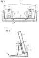
- FIG. 1a receiving device 1 for a portable electronic device 2 is shown.
- a base plate 9By the arrangement of a base plate 9, a rear wall 10 (see FIG. 2 ) of a first side wall 11 and a second side wall 12, wherein the first side wall 11 together with a first front part 11a to a first corner 11b and the second side wall 12th are arranged together with a second front part 12a to a second corner 12b, is provided by the receiving device 1, a large capture area F for a secure docking of the electronic device 2 in the receiving device 1.
- FIG. 2shows in a cross-sectional view of the receiving device 1, the mechanical design features within the receiving device 1, which allow a sliding and a secure forced feeding a Hästeckenden electronic device 2 in the receiving device 1.
- the first front part 11a and the second front part 12aare each divided into a first area B1 directed towards the rear wall 10 and a second area B2.
- the viewis directed only to the second front part 12a.
- the first region B1has a sliding surface GF, which at a first angle ⁇ 1 conical to the rear wall 10 and the second region B2 has a positive guide surface ZF, which is arranged at a second angle ⁇ 2 to the rear wall, wherein the first angle ⁇ 1 is greater than the second angle ⁇ 1.
- a transition from the sliding surface GF to the forced guiding surface ZFforms a cam, two sliding tracks GB1, GB2, each having a first sliding track area GBB1 and a second sliding track area GBB2, being arranged on the rear wall.
- Another transition from the first slide track area GBB1 to the second slide track area GBB2forms another cam.
- the cam and the further camare arranged such that in the event that the portable electronic device 2 is inserted into the receiving device 1, the cams ensure that the portable electronic device from an initial sliding movement on the respective sliding surfaces GF on reaching the Cam is inclined to the rear wall.
- the catching area F of the receiving device 1is clarified.
- the first side wall 11 and the second side wall 12are arranged such that they diverge conically, whereby a funnel-shaped catching area F is formed for the portable electronic device 2 to be inserted.
- a contact element 20is arranged with a plurality of contact pins, wherein the contact element 20 between a first Vorzentri réellesdom 21 and a second Vorzentri réellesdom 22 is arranged.
- a first magnetic element M1 and a second magnetic element M2is arranged, which with a counter-magnet element G2 (see FIG. 4 ) interact.
- the first magnetic element M1is surrounded by a first collar K1 and the second magnetic element M2 is surrounded by a second collar K2, wherein the two collars K1, K2 are formed so that they form-fit with an inserted portable electronic device 2 with the respective recess A2 in engage inserted portable electronic device 2.
- the magnetic elements M1, M2 and the collar K1, K2creates a positive and positive fixed locking in the receiving device 1 for the portable electronic device. 2
- a first switching means 31 and a second switching means 32are arranged, which are configured such that the first switching means 31 and the second switching means 32 is activated when the first collar K1 and the second collar K2 in the respective recess A2 of electronic device 2 is locked.
- a release means 30is provided, which is in communication with the first switching means 31 and the second switching means 32 and is configured to release a data transmission via the contact element 20 to the portable electronic device 2 only when the switching means 31,32 is activated.
- FIG. 4is shown in a sectional view of the recording device 1 and the portable electronic device 2, how the portable electronic device 2 is securely docked in the receiving device 1.
- the second magnetic element M2 and the recess A1it is made clear that a non-positive and positive connection between the receiving device 1 and the portable electronic device 2 prevails at this point.
- An arranged in the portable electronic device counter-magnet element G2supports this non-positive and positive connection.
Landscapes
- Engineering & Computer Science (AREA)
- Theoretical Computer Science (AREA)
- Computer Hardware Design (AREA)
- Human Computer Interaction (AREA)
- Physics & Mathematics (AREA)
- General Engineering & Computer Science (AREA)
- General Physics & Mathematics (AREA)
- Signal Processing (AREA)
- Casings For Electric Apparatus (AREA)
- Telephone Set Structure (AREA)
Abstract
Translated fromGermanDescription
Translated fromGermanDie Erfindung betrifft eine Aufnahmevorrichtung für ein tragbares elektronisches Gerät, umfassend eine Grundplatte, eine Rückwand, eine erste Seitenwand und eine zweite Seitenwand, wobei die erste Seitenwand zusammen mit einem ersten Vorderteil zu einer ersten Ecke und die zweite Seitenwand zusammen mit einem zweiten Vorderteil zu einer zweiten Ecke angeordnet sind.The invention relates to a receiving device for a portable electronic device comprising a base plate, a rear wall, a first side wall and a second side wall, wherein the first side wall together with a first front part to a first corner and the second side wall together with a second front part to a second corner are arranged.
Im Sinne der Erfindung wird unter einem tragbaren elektronischen Gerät, insbesondere ein Notebook oder ein Tablet-PC verstanden.For the purposes of the invention is understood by a portable electronic device, in particular a notebook or a tablet PC.
Aus der europäischen Patentanmeldung
Es ist Aufgabe der vorliegenden Erfindung eine Aufnahmevorrichtung bereitzustellen, die eine einfache Handhabung und eine möglichst einhändige Bedienung ermöglicht.It is an object of the present invention to provide a receiving device, which allows easy handling and one-handed operation possible.
Die Aufgabe wird für die eingangs genannte Aufnahmevorrichtung dadurch gelöst, dass der erste Vorderteil und der zweite Vorderteil jeweils einen zur Rückwand gerichteten ersten Bereich und einen zweiten Bereich aufweist, wobei der erste Bereich eine Gleitfläche aufweist, welche in einem ersten Winkel konisch zur Rückwand und der zweite Bereich eine Zwangsführungsfläche aufweist, welche in einem zweiten Winkel zur Rückwand angeordnet ist, wobei der erste Winkel größer ist als der zweite Winkel, wobei ein Übergang von der Gleitfläche zur Zwangsführungsfläche eine Nocke bildet, wobei auf der Rückwand zwei Gleitbahnen mit jeweils einem ersten Gleitbahnbereich und einen zweiten Gleitbahnbereich angeordnet sind, wobei ein weiterer Übergang von dem ersten Gleitbahnbereich zu dem zweiten Gleitbahnbereich eine weitere Nocke bildet, wobei für den Fall, dass das tragbare elektronische Gerät in die Aufnahmevorrichtung gesteckt wird, bewirken die Nocken, dass das tragbare elektronische Gerät von einer anfänglichen Gleitbewegung über die entsprechenden Gleitflächen bei Erreichung der Nocken zur Rückwand geneigt wird.The object is achieved for the receiving device mentioned above in that the first front part and the second front part each have a directed to the rear wall first region and a second region, wherein the first region has a sliding surface which conically at a first angle to the rear wall and the second region has a positive guide surface which is disposed at a second angle to the rear wall, wherein the first angle is greater than the second angle, wherein a transition from the sliding surface to the forced guide surface forms a cam, wherein on the rear wall two slideways each having a first slideway region and a second slide track region, wherein a further transition from the first slide track region to the second slide track region forms a further cam, wherein in the event that the portable electronic device is plugged into the recording device, the cams cause the portable electronic device of an initial sliding movement over the respective sliding surfaces on reaching the cam is inclined to the rear wall.
Durch die beschriebene Anordnung der Gleitflächen und Zwangsführungsflächen ist es möglich, das tragbare elektronische Gerät einhändig über der Aufnahmevorrichtung zu positionieren und leicht in die Aufnahmevorrichtung einzuschieben. Es ist darüber hinaus sogar möglich, einfach das tragbare elektronische Gerät einhändig über der Aufnahmevorrichtung zu positionieren und einfach loszulassen, denn über die in der Aufnahmevorrichtung angeordneten Bereiche, Gleitflächen und Zwangsführungsflächen und die auf das Gerät wirkende Schwerkraft wird das Gerät von alleine richtig positioniert. Durch eine anfängliche Gleitbewegung des tragbaren elektronischen Gerätes auf der Gleitfläche trifft es schließlich auf die durch den Übergang von der Gleitfläche zur Zwangsführungsfläche gebildete Nocke, welche dafür sorgt, dass das Gleiten des elektronischen Gerätes in ein Neigen übergeht. Unterstützt wird dieser Übergang von Gleiten in ein Neigen durch die weitere Nocke, welche durch den Übergang von dem ersten Gleitbahnbereich zu dem zweiten Gleitbahnbereich gebildet ist. Durch die Anordnung der Nocken, welche letztendlich für eine Zwangsführung des tragbaren elektronischen Gerätes sorgen, wird eine stufenweise Zentrierung des tragbaren elektronischen Gerätes ermöglicht.The described arrangement of the sliding surfaces and positive guide surfaces, it is possible to position the portable electronic device with one hand on the receiving device and easy to insert into the receiving device. Moreover, it is even possible simply to position the portable electronic device one-handedly over the recording device and simply let it go, because on the arranged in the receiving device areas, sliding surfaces and forced guidance surfaces and the force acting on the device gravity, the device is properly positioned by itself. By an initial sliding movement of the portable electronic device on the sliding surface, it finally encounters the cam formed by the transition from the sliding surface to the forced guiding surface, which ensures that the sliding of the electronic device changes into a tilt. This transition from sliding to tilting is assisted by the further cam, which is formed by the transition from the first slide track area to the second slide track area. The arrangement of the cams, which ultimately provide for positive guidance of the portable electronic device, a gradual centering of the portable electronic device is made possible.
In einer weiteren Ausgestaltung sind die Seitenwände derart zueinander angeordnet, dass diese konisch auseinanderlaufen, wodurch ein trichterförmiger Fangbereich für das einzusteckende tragbare elektronische Gerät gebildet ist. Ein trichterförmiger Fangbereich bzw. ein großer Fangbereich vereinfacht ein einhändiges Einstecken in die Aufnahmevorrichtung nochmals. In einem Extremfall könnte man sogar das elektronische Gerät einfach in die Aufnahmevorrichtung einwerfen und durch den trichterförmigen großen Fangbereich und im Wesentlichen durch die Gleit- und Zwangsführungsflächen wird das elektronische Gerät in der Aufnahmevorrichtung sich selbständig positionieren und letztendlich einen Kontakt mit einem in der Aufnahmevorrichtung angeordneten Kontaktelement eingehen.In a further embodiment, the side walls are arranged to each other such that they diverge conically, whereby a funnel-shaped catching area for the einzusteckende portable electronic device is formed. A funnel-shaped catching area or a large catching area simplifies a one-handed insertion into the receiving device again. In an extreme case, one could even simply insert the electronic device into the receiving device and, through the funnel-shaped large capture region and essentially through the sliding and forced guiding surfaces, the electronic device in the receiving device will position itself and ultimately make contact with a contact element arranged in the receiving device received.
Für die Kontaktierung ist auf der Grundplatte ein Kontaktelement mit einer Vielzahl von Kontaktstiften angeordnet, wobei das Kontaktelement zwischen einem ersten Vorzentrierungsdom und einem zweiten Vorzentrierungsdom angeordnet ist. Die Vorzentrierung durch die Vorzentrierungsdome ist für die sichere Positionierung des elektronischen Gerätes mit ebenfalls einen Gegenkontaktelement auf das Kontaktelement der Aufnahmevorrichtung vorgesehen. Rutscht das elektronische Gerät in Richtung des Kontaktelementes, so wird es durch die Vorzentrierungsdome in die richtige Richtung geführt, letztendlich befinden sich auf dem Kontaktelement noch zusätzliche Steckkontaktdome die für eine Schlusszentrierung des Gegenkontaktelementes des tragbaren elektronischen Gerätes auf das Kontaktelement der Aufnahmevorrichtung sorgen.For contacting a contact element with a plurality of contact pins is arranged on the base plate, wherein the contact element between a first Vorzentrierungsdom and a second Vorzentrierungsdom is arranged. The pre-centering by the Vorzentrierungsdome is provided for the secure positioning of the electronic device with also a mating contact element on the contact element of the receiving device. Slips the electronic device in the direction of the contact element, it is guided by the Vorzentrierungsdome in the right direction, ultimately there are on the contact element additional plug contact dome provide for a final centering of the mating contact element of the portable electronic device on the contact element of the recording device.
In einer weiteren Ausgestaltung ist in der Rückwand ein Magnetelement angeordnet, welches mit einem Gegenmagnetelement im tragbaren elektronischen Gerat zusammenwirkt, wobei das Magnetelement von einem Kragen umgeben ist, welcher derart ausgebildet ist, dass er bei eingestecktem tragbaren elektronischen Gerät formschlüssig mit einer Ausnehmung im eingesteckten tragbaren elektronischem Gerät verrastet. Somit entsteht eine kraft- und formschlüssige Verbindung zwischen tragbaren elektronischem Gerät und Aufnahmevorrichtung.In a further embodiment, a magnetic element is arranged in the rear wall, which cooperates with a counter-magnet element in the portable electronic device, wherein the magnetic element is surrounded by a collar which is designed such that it with a plug-in portable electronic device form-fitting with a recess in the inserted portable locked electronic device. This creates a non-positive and positive connection between the portable electronic device and recording device.
Durch den Einsatz beispielsweise zweier Magnete in der Rückwand der Aufnahmevorrichtung (links und rechts) sowie durch den Einsatz von beispielsweise magnetischen Stahlscheiben in dem tragbaren elektronischen Gerät, welche in einer Vertiefung eingelassen sind und wird zusätzlich für eine formschlüssige Verbindung des tragbaren elektronischen Gerätes mit der Aufnahmevorrichtung gesorgt.By using, for example, two magnets in the rear wall of the receiving device (left and right) and by the use of, for example, magnetic steel discs in the portable electronic device, which are embedded in a recess and is additionally for a positive Connection of the portable electronic device with the recording device taken care of.
In einer weiter optimierten Ausgestaltung ist in der Rückwand ein Schaltmittel angeordnet, welches derart ausgestaltet ist, dass das Schaltmittel aktiviert wird, wenn der Kragen in der Ausnehmung verrastet ist. Weiterhin ist es von Vorteil, wenn das Kontaktelement federunterstützte Kontaktstifte aufweist. Zusätzlich ist es vorteilhaft, wenn ein Freigabemittel vorhanden ist, welches mit dem Schaltmittel in Verbindung steht und ausgestaltet ist, eine Datenübertragung über das Kontaktelement zu dem tragbaren elektronischen Gerät erst freizugeben, wenn das Schaltmittel aktiviert ist.In a further optimized embodiment, a switching means is arranged in the rear wall, which is designed such that the switching means is activated when the collar is locked in the recess. Furthermore, it is advantageous if the contact element has spring-assisted contact pins. In addition, it is advantageous if a release means is present, which is in communication with the switching means and is configured to release data transmission via the contact element to the portable electronic device only when the switching means is activated.
Durch die Kombination von mechanischem Gesperre, in Form eines Formschlusses, den Einsatz von Magnetelementen und Gegenmagnetelementen, dem Kontaktelement, insbesondere ausgeführt als sogenannte Pogo-Pins, und optionalen Schaltmitteln, insbesondere ausgeführt als Mikroschaltern zur kontrollierten Kontaktunterbrechung, ist die Aufnahmevorrichtung in dieser Ausprägungsform bezüglich des sicheren Kontaktierens zwischen dem elektronischen Gerät und der Aufnahmevorrichtung besonders robust ausgestaltet. Zusätzliche Möglichkeiten würden sich durch den Einsatz von Elektro-Magneten ergeben, welche nach einem letztendlichen Positionieren ein unerwünschtes Entnehmen des tragbaren elektronischen Gerätes ausschließen würden.Through the combination of mechanical locking, in the form of a positive connection, the use of magnetic elements and countermagnetic elements, the contact element, in particular embodied as so-called pogo pins, and optional switching means, in particular designed as micro-switches for controlled contact interruption, the receiving device in this form of expression with respect to secure contacting between the electronic device and the recording device designed particularly robust. Additional possibilities would result from the use of electro-magnets, which would preclude unwanted removal of the portable electronic device after eventual positioning.
Durch die form- und kraftschlüssige Magnetverriegelung hat nun ein Bediener des elektronischen Gerätes während der Bedienung die Sicherheit das die Kontaktierung von dem elektronischen Gerät zu der Aufnahmevorrichtung immer gewährleistet ist, welches für eine Datenübertragung zu einer übergeordneten Automatisierungskomponente oder Serverkomponente von großer Wichtigkeit ist.Due to the positive and non-positive magnetic locking now an operator of the electronic device during operation has the security that the contacting of the electronic device to the recording device is always guaranteed, which is for data transmission to a higher-level automation component or server component of great importance.
Eine anschließende Entriegelung bzw. Entnahme des elektronischen Gerätes aus der Aufnahmevorrichtung würde sich wie folgt gestalten:A subsequent unlocking or removal of the electronic device from the receiving device would be as follows:
Das elektronische Gerät leicht nach vorne Ziehen, wodurch die Magnetverriegelung gelöst wird.Pull the electronic device slightly forward, releasing the magnetic latch.
Das elektronische Gerät kann nun nach oben herausgezogen werden, wodurch die Kontaktierung unterbrochen wird.The electronic device can now be pulled upwards, whereby the contact is interrupted.
Da nun die Schaltmittel nicht mehr betätigt sind und das Gerät sicher und gleichmäßig von den Kontaktelementen gelöst wird, ergibt sich kein Systemabsturz oder Datenverlust.Since now the switching means are no longer actuated and the device is safely and evenly released from the contact elements, there is no system crash or data loss.
Die Zeichnung zeigt ein Ausführungsbeispiel der Erfindung. Es zeigen:
- FIG 1
- eine perspektivische Ansicht einer Aufnahmevorrichtung für ein tragbares elektronisches Gerät,
- FIG 2
- die Aufnahmevorrichtung in einer Schnittdarstellung,
- FIG 3
- die Aufnahmevorrichtung in einer Längsschnittdarstellung und
- FIG 4
- die Aufnahmevorrichtung mit dem elektronischen Gerät.
- FIG. 1
- a perspective view of a receptacle for a portable electronic device,
- FIG. 2
- the receiving device in a sectional view,
- FIG. 3
- the recording device in a longitudinal sectional view and
- FIG. 4
- the recording device with the electronic device.
Gemäß
Die
Der erste Bereich B1 weist eine Gleitfläche GF auf, welche in einem ersten Winkel α1 konisch zur Rückwand 10 und der zweite Bereich B2 weist eine Zwangsführungsfläche ZF auf, welche in einem zweiten Winkel α2 zur Rückwand angeordnet ist, wobei der erste Winkel α1 größer ist als der zweite Winkel α1.The first region B1 has a sliding surface GF, which at a first angle α1 conical to the
Ein Übergang von der Gleitfläche GF zur Zwangsführungsfläche ZF bildet eine Nocke, wobei auf der Rückwand zwei Gleitbahnen GB1,GB2 mit jeweils einem ersten Gleitbahnbereich GBB1 und einem zweiten Gleitbahnbereich GBB2 angeordnet sind.A transition from the sliding surface GF to the forced guiding surface ZF forms a cam, two sliding tracks GB1, GB2, each having a first sliding track area GBB1 and a second sliding track area GBB2, being arranged on the rear wall.
Ein weiterer Übergang von dem ersten Gleitbahnbereich GBB1 zu dem zweiten Gleitbahnbereich GBB2 bildet eine weitere Nocke. Die Nocke und die weitere Nocke sind derart angeordnet, dass für den Fall, dass das tragbare elektronische Gerät 2 in die Aufnahmevorrichtung 1 gesteckt wird, die Nocken dafür sorgen, dass das tragbare elektronische Gerät von einer anfänglichen Gleitbewegung über die entsprechenden Gleitflächen GF bei Erreichen der Nocken zur Rückwand geneigt wird.Another transition from the first slide track area GBB1 to the second slide track area GBB2 forms another cam. The cam and the further cam are arranged such that in the event that the portable
Mit der
In der Rückwand 10 ist ein erstes Schaltmittel 31 und ein zweites Schaltmittel 32 angeordnet, welche derart ausgestaltet sind, dass das erste Schaltmittel 31 und das zweite Schaltmittel 32 aktiviert wird, wenn der erste Kragen K1 und der zweite Kragen K2 in der jeweiligen Ausnehmung A2 des elektronischen Gerätes 2 verrastet ist.In the
Mit Bezug auf
Gemäß der
Claims (7)
Translated fromGermaneine Grundplatte (9),
eine Rückwand (10),
eine erste Seitenwand (11) und
eine zweite Seitenwand (12),
wobei die erste Seitenwand (11) zusammen mit einem ersten Vorderteil (11a) zu einer ersten Ecke (11b) und die zweite Seitenwand (12) zusammen mit einem zweiten Vorderteil (12a) zu einer zweiten Ecke (12b) angeordnet sind,
dadurch gekennzeichnet, dass der erste Vorderteil (11a) und der zweite Vorderteil (12a) jeweils einen zur Rückwand gerichteten ersten Bereich (B1) und einen zweiten Bereich (B2) aufweist, wobei der erste Bereich (B1) eine Gleitfläche (GF) aufweist, welche in einem ersten Winkel (α1) konisch zur Rückwand (10) und der zweite Bereich (B2) eine Zwangsführungsfläche (ZF) aufweist, welche in einem zweiten Winkel (α2) zur Rückwand (10) angeordnet ist, wobei der erste Winkel (α1) größer ist als der zweite Winkel (α2), wobei ein Übergang von der Gleitfläche (GF) zur Zwangsführungsfläche (ZF) eine Nocke bildet, wobei auf der Rückwand (10) zwei Gleitbahnen (GB1,GB2) mit jeweils einem ersten Gleitbahnbereich (GBB1) und einem zweiten Gleitbahnbereich (GBB2) angeordnet sind, wobei ein weiterer Übergang von dem ersten Gleitbahnbereich (GBB1) zu dem zweiten Gleitbahnbereich (GBB2) eine weitere Nocke bildet, wobei für den Fall, dass das tragbare elektronische Gerät (2) in die Aufnahmevorrichtung (1) gesteckt wird, die Nocken bewirken, dass das tragbare elektronische Gerät (2) von einer anfänglichen Gleitbewegung über die entsprechenden Gleit-Flächen (GF) bei Erreichen der Nocken zur Rückwand (10) geneigt wird.Recording device (1) for a portable electronic device (2), comprising
a base plate (9),
a back wall (10),
a first side wall (11) and
a second side wall (12),
wherein the first side wall (11) is arranged together with a first front part (11a) to a first corner (11b) and the second side wall (12) together with a second front part (12a) to a second corner (12b)
characterized in that the first front part (11a) and the second front part (12a) each have a first region (B1) directed towards the rear wall and a second region (B2), the first region (B1) having a sliding surface (GF), which at a first angle (α1) conically to the rear wall (10) and the second region (B2) has a positive guide surface (ZF), which at a second angle (α2) to the rear wall (10) is arranged, wherein the first angle (α1 ) is greater than the second angle (α2), wherein a transition from the sliding surface (GF) to the forced guide surface (ZF) forms a cam, wherein on the rear wall (10) has two slide tracks (GB1, GB2) each having a first slide track area (GBB1 ) and a second slide track area (GBB2), wherein a further transition from the first slide track area (GBB1) to the second slide track area (GBB2) forms a further cam, wherein in the event that the portable electronic device (2) in the Aufnah 1, the cams cause the portable electronic device (2) to be tilted from initial sliding movement over the respective sliding surfaces (GF) on reaching the cams to the rear wall (10).
Priority Applications (1)
| Application Number | Priority Date | Filing Date | Title |
|---|---|---|---|
| EP16178161.2AEP3267283B1 (en) | 2016-07-06 | 2016-07-06 | Holder apparatus for a portable electronic device |
Applications Claiming Priority (1)
| Application Number | Priority Date | Filing Date | Title |
|---|---|---|---|
| EP16178161.2AEP3267283B1 (en) | 2016-07-06 | 2016-07-06 | Holder apparatus for a portable electronic device |
Publications (2)
| Publication Number | Publication Date |
|---|---|
| EP3267283A1true EP3267283A1 (en) | 2018-01-10 |
| EP3267283B1 EP3267283B1 (en) | 2018-12-26 |
Family
ID=56409481
Family Applications (1)
| Application Number | Title | Priority Date | Filing Date |
|---|---|---|---|
| EP16178161.2AActiveEP3267283B1 (en) | 2016-07-06 | 2016-07-06 | Holder apparatus for a portable electronic device |
Country Status (1)
| Country | Link |
|---|---|
| EP (1) | EP3267283B1 (en) |
Citations (6)
| Publication number | Priority date | Publication date | Assignee | Title |
|---|---|---|---|---|
| DE69528940T2 (en)* | 1994-09-08 | 2003-07-17 | Nokia Corp., Espoo | Holder for a radio telephone |
| EP2096516A2 (en) | 2008-02-26 | 2009-09-02 | ads-tec GmbH | Docking station with a quick connector for a mobile electronic device |
| US20090280871A1 (en)* | 2008-05-12 | 2009-11-12 | Research In Motion Limited | Communication device |
| US20100146308A1 (en)* | 2008-09-26 | 2010-06-10 | Richard Gioscia | Portable power supply device for mobile computing devices |
| US20120299547A1 (en)* | 2011-05-26 | 2012-11-29 | Hon Hai Precision Industry Co., Ltd. | Charging assembly for electronic device |
| US20150016051A1 (en)* | 2013-07-15 | 2015-01-15 | Toshiba Global Commerce Solutions Holdings Corporation | Display assembly having graduated magnetic fastening characteristics |
- 2016
- 2016-07-06EPEP16178161.2Apatent/EP3267283B1/enactiveActive
Patent Citations (6)
| Publication number | Priority date | Publication date | Assignee | Title |
|---|---|---|---|---|
| DE69528940T2 (en)* | 1994-09-08 | 2003-07-17 | Nokia Corp., Espoo | Holder for a radio telephone |
| EP2096516A2 (en) | 2008-02-26 | 2009-09-02 | ads-tec GmbH | Docking station with a quick connector for a mobile electronic device |
| US20090280871A1 (en)* | 2008-05-12 | 2009-11-12 | Research In Motion Limited | Communication device |
| US20100146308A1 (en)* | 2008-09-26 | 2010-06-10 | Richard Gioscia | Portable power supply device for mobile computing devices |
| US20120299547A1 (en)* | 2011-05-26 | 2012-11-29 | Hon Hai Precision Industry Co., Ltd. | Charging assembly for electronic device |
| US20150016051A1 (en)* | 2013-07-15 | 2015-01-15 | Toshiba Global Commerce Solutions Holdings Corporation | Display assembly having graduated magnetic fastening characteristics |
Also Published As
| Publication number | Publication date |
|---|---|
| EP3267283B1 (en) | 2018-12-26 |
Similar Documents
| Publication | Publication Date | Title |
|---|---|---|
| DE69919083T2 (en) | Fiber optic connector | |
| EP2904982B1 (en) | Electrosurgical device having a female insert, set with a removing tool and method of removing a female insert | |
| EP1499171B1 (en) | Device for inserting, extracting a plug-in unit in a bay | |
| DE10221862A1 (en) | Plug connection to prevent an incompletely connected state | |
| DE102014011243A1 (en) | knife | |
| DE102014113324A1 (en) | Protective cap for connectors | |
| DE102014112258B4 (en) | clip system | |
| EP3669428A1 (en) | Sealing device for a plug-in connection | |
| AT520279B1 (en) | hinge | |
| DE102016115740A1 (en) | Change system, in particular for the detachable arrangement of handling devices on robot arms | |
| EP1914094B1 (en) | Rapid connection element | |
| EP3224001B1 (en) | Self-locking latch of an adapter device | |
| EP2985573B1 (en) | Apparatus and method of fastening an electronic device | |
| DE102016100767B4 (en) | STRUCTURE FOR FIXING A PCB IN AN ELECTRONIC DEVICE UNIT | |
| DE102017001943A1 (en) | connection system | |
| EP3267283B1 (en) | Holder apparatus for a portable electronic device | |
| DE102009030307B4 (en) | Connectors and assembly methods therefor | |
| DE102009060097A1 (en) | Covering device has length-adjustable protective cover movable along axis and coupling mechanism, which has fixed coupling element not movable with protection cover | |
| EP3502356B1 (en) | Quick coupling, adapter and quick coupling system | |
| EP2713450A1 (en) | Plug connector and method for operating the same | |
| DE19812085A1 (en) | Mounting device for components | |
| EP1350962B1 (en) | Modul assembly with locking key elements | |
| DE3310474A1 (en) | Assembly for pushing into mounting racks having a lock, and devices for removing the assembly and releasing the lock | |
| EP2031156B1 (en) | Reset mechanism for a door handle | |
| EP2783598B1 (en) | Furniture item with coupling device |
Legal Events
| Date | Code | Title | Description |
|---|---|---|---|
| PUAI | Public reference made under article 153(3) epc to a published international application that has entered the european phase | Free format text:ORIGINAL CODE: 0009012 | |
| STAA | Information on the status of an ep patent application or granted ep patent | Free format text:STATUS: THE APPLICATION HAS BEEN PUBLISHED | |
| AK | Designated contracting states | Kind code of ref document:A1 Designated state(s):AL AT BE BG CH CY CZ DE DK EE ES FI FR GB GR HR HU IE IS IT LI LT LU LV MC MK MT NL NO PL PT RO RS SE SI SK SM TR | |
| AX | Request for extension of the european patent | Extension state:BA ME | |
| STAA | Information on the status of an ep patent application or granted ep patent | Free format text:STATUS: REQUEST FOR EXAMINATION WAS MADE | |
| 17P | Request for examination filed | Effective date:20180619 | |
| RBV | Designated contracting states (corrected) | Designated state(s):AL AT BE BG CH CY CZ DE DK EE ES FI FR GB GR HR HU IE IS IT LI LT LU LV MC MK MT NL NO PL PT RO RS SE SI SK SM TR | |
| RIC1 | Information provided on ipc code assigned before grant | Ipc:H04M 1/06 20060101ALI20180711BHEP Ipc:G06F 1/16 20060101AFI20180711BHEP Ipc:H02J 7/00 20060101ALI20180711BHEP | |
| GRAP | Despatch of communication of intention to grant a patent | Free format text:ORIGINAL CODE: EPIDOSNIGR1 | |
| STAA | Information on the status of an ep patent application or granted ep patent | Free format text:STATUS: GRANT OF PATENT IS INTENDED | |
| INTG | Intention to grant announced | Effective date:20180821 | |
| GRAS | Grant fee paid | Free format text:ORIGINAL CODE: EPIDOSNIGR3 | |
| GRAA | (expected) grant | Free format text:ORIGINAL CODE: 0009210 | |
| STAA | Information on the status of an ep patent application or granted ep patent | Free format text:STATUS: THE PATENT HAS BEEN GRANTED | |
| AK | Designated contracting states | Kind code of ref document:B1 Designated state(s):AL AT BE BG CH CY CZ DE DK EE ES FI FR GB GR HR HU IE IS IT LI LT LU LV MC MK MT NL NO PL PT RO RS SE SI SK SM TR | |
| REG | Reference to a national code | Ref country code:GB Ref legal event code:FG4D Free format text:NOT ENGLISH | |
| REG | Reference to a national code | Ref country code:CH Ref legal event code:EP | |
| REG | Reference to a national code | Ref country code:AT Ref legal event code:REF Ref document number:1082286 Country of ref document:AT Kind code of ref document:T Effective date:20190115 | |
| REG | Reference to a national code | Ref country code:DE Ref legal event code:R096 Ref document number:502016002956 Country of ref document:DE | |
| REG | Reference to a national code | Ref country code:IE Ref legal event code:FG4D Free format text:LANGUAGE OF EP DOCUMENT: GERMAN | |
| PG25 | Lapsed in a contracting state [announced via postgrant information from national office to epo] | Ref country code:FI Free format text:LAPSE BECAUSE OF FAILURE TO SUBMIT A TRANSLATION OF THE DESCRIPTION OR TO PAY THE FEE WITHIN THE PRESCRIBED TIME-LIMIT Effective date:20181226 Ref country code:BG Free format text:LAPSE BECAUSE OF FAILURE TO SUBMIT A TRANSLATION OF THE DESCRIPTION OR TO PAY THE FEE WITHIN THE PRESCRIBED TIME-LIMIT Effective date:20190326 Ref country code:HR Free format text:LAPSE BECAUSE OF FAILURE TO SUBMIT A TRANSLATION OF THE DESCRIPTION OR TO PAY THE FEE WITHIN THE PRESCRIBED TIME-LIMIT Effective date:20181226 Ref country code:NO Free format text:LAPSE BECAUSE OF FAILURE TO SUBMIT A TRANSLATION OF THE DESCRIPTION OR TO PAY THE FEE WITHIN THE PRESCRIBED TIME-LIMIT Effective date:20190326 Ref country code:LT Free format text:LAPSE BECAUSE OF FAILURE TO SUBMIT A TRANSLATION OF THE DESCRIPTION OR TO PAY THE FEE WITHIN THE PRESCRIBED TIME-LIMIT Effective date:20181226 Ref country code:LV Free format text:LAPSE BECAUSE OF FAILURE TO SUBMIT A TRANSLATION OF THE DESCRIPTION OR TO PAY THE FEE WITHIN THE PRESCRIBED TIME-LIMIT Effective date:20181226 | |
| REG | Reference to a national code | Ref country code:NL Ref legal event code:MP Effective date:20181226 | |
| REG | Reference to a national code | Ref country code:LT Ref legal event code:MG4D | |
| PG25 | Lapsed in a contracting state [announced via postgrant information from national office to epo] | Ref country code:AL Free format text:LAPSE BECAUSE OF FAILURE TO SUBMIT A TRANSLATION OF THE DESCRIPTION OR TO PAY THE FEE WITHIN THE PRESCRIBED TIME-LIMIT Effective date:20181226 Ref country code:SE Free format text:LAPSE BECAUSE OF FAILURE TO SUBMIT A TRANSLATION OF THE DESCRIPTION OR TO PAY THE FEE WITHIN THE PRESCRIBED TIME-LIMIT Effective date:20181226 Ref country code:RS Free format text:LAPSE BECAUSE OF FAILURE TO SUBMIT A TRANSLATION OF THE DESCRIPTION OR TO PAY THE FEE WITHIN THE PRESCRIBED TIME-LIMIT Effective date:20181226 Ref country code:GR Free format text:LAPSE BECAUSE OF FAILURE TO SUBMIT A TRANSLATION OF THE DESCRIPTION OR TO PAY THE FEE WITHIN THE PRESCRIBED TIME-LIMIT Effective date:20190327 | |
| PG25 | Lapsed in a contracting state [announced via postgrant information from national office to epo] | Ref country code:NL Free format text:LAPSE BECAUSE OF FAILURE TO SUBMIT A TRANSLATION OF THE DESCRIPTION OR TO PAY THE FEE WITHIN THE PRESCRIBED TIME-LIMIT Effective date:20181226 | |
| PG25 | Lapsed in a contracting state [announced via postgrant information from national office to epo] | Ref country code:ES Free format text:LAPSE BECAUSE OF FAILURE TO SUBMIT A TRANSLATION OF THE DESCRIPTION OR TO PAY THE FEE WITHIN THE PRESCRIBED TIME-LIMIT Effective date:20181226 Ref country code:PL Free format text:LAPSE BECAUSE OF FAILURE TO SUBMIT A TRANSLATION OF THE DESCRIPTION OR TO PAY THE FEE WITHIN THE PRESCRIBED TIME-LIMIT Effective date:20181226 Ref country code:PT Free format text:LAPSE BECAUSE OF FAILURE TO SUBMIT A TRANSLATION OF THE DESCRIPTION OR TO PAY THE FEE WITHIN THE PRESCRIBED TIME-LIMIT Effective date:20190426 Ref country code:CZ Free format text:LAPSE BECAUSE OF FAILURE TO SUBMIT A TRANSLATION OF THE DESCRIPTION OR TO PAY THE FEE WITHIN THE PRESCRIBED TIME-LIMIT Effective date:20181226 | |
| PG25 | Lapsed in a contracting state [announced via postgrant information from national office to epo] | Ref country code:SK Free format text:LAPSE BECAUSE OF FAILURE TO SUBMIT A TRANSLATION OF THE DESCRIPTION OR TO PAY THE FEE WITHIN THE PRESCRIBED TIME-LIMIT Effective date:20181226 Ref country code:IS Free format text:LAPSE BECAUSE OF FAILURE TO SUBMIT A TRANSLATION OF THE DESCRIPTION OR TO PAY THE FEE WITHIN THE PRESCRIBED TIME-LIMIT Effective date:20190426 Ref country code:RO Free format text:LAPSE BECAUSE OF FAILURE TO SUBMIT A TRANSLATION OF THE DESCRIPTION OR TO PAY THE FEE WITHIN THE PRESCRIBED TIME-LIMIT Effective date:20181226 Ref country code:SM Free format text:LAPSE BECAUSE OF FAILURE TO SUBMIT A TRANSLATION OF THE DESCRIPTION OR TO PAY THE FEE WITHIN THE PRESCRIBED TIME-LIMIT Effective date:20181226 Ref country code:EE Free format text:LAPSE BECAUSE OF FAILURE TO SUBMIT A TRANSLATION OF THE DESCRIPTION OR TO PAY THE FEE WITHIN THE PRESCRIBED TIME-LIMIT Effective date:20181226 | |
| REG | Reference to a national code | Ref country code:DE Ref legal event code:R097 Ref document number:502016002956 Country of ref document:DE | |
| PG25 | Lapsed in a contracting state [announced via postgrant information from national office to epo] | Ref country code:DK Free format text:LAPSE BECAUSE OF FAILURE TO SUBMIT A TRANSLATION OF THE DESCRIPTION OR TO PAY THE FEE WITHIN THE PRESCRIBED TIME-LIMIT Effective date:20181226 | |
| PLBE | No opposition filed within time limit | Free format text:ORIGINAL CODE: 0009261 | |
| STAA | Information on the status of an ep patent application or granted ep patent | Free format text:STATUS: NO OPPOSITION FILED WITHIN TIME LIMIT | |
| 26N | No opposition filed | Effective date:20190927 | |
| PG25 | Lapsed in a contracting state [announced via postgrant information from national office to epo] | Ref country code:SI Free format text:LAPSE BECAUSE OF FAILURE TO SUBMIT A TRANSLATION OF THE DESCRIPTION OR TO PAY THE FEE WITHIN THE PRESCRIBED TIME-LIMIT Effective date:20181226 Ref country code:MC Free format text:LAPSE BECAUSE OF FAILURE TO SUBMIT A TRANSLATION OF THE DESCRIPTION OR TO PAY THE FEE WITHIN THE PRESCRIBED TIME-LIMIT Effective date:20181226 | |
| REG | Reference to a national code | Ref country code:CH Ref legal event code:PL | |
| PG25 | Lapsed in a contracting state [announced via postgrant information from national office to epo] | Ref country code:TR Free format text:LAPSE BECAUSE OF FAILURE TO SUBMIT A TRANSLATION OF THE DESCRIPTION OR TO PAY THE FEE WITHIN THE PRESCRIBED TIME-LIMIT Effective date:20181226 | |
| REG | Reference to a national code | Ref country code:BE Ref legal event code:MM Effective date:20190731 | |
| PG25 | Lapsed in a contracting state [announced via postgrant information from national office to epo] | Ref country code:CH Free format text:LAPSE BECAUSE OF NON-PAYMENT OF DUE FEES Effective date:20190731 Ref country code:LI Free format text:LAPSE BECAUSE OF NON-PAYMENT OF DUE FEES Effective date:20190731 Ref country code:LU Free format text:LAPSE BECAUSE OF NON-PAYMENT OF DUE FEES Effective date:20190706 Ref country code:BE Free format text:LAPSE BECAUSE OF NON-PAYMENT OF DUE FEES Effective date:20190731 | |
| PG25 | Lapsed in a contracting state [announced via postgrant information from national office to epo] | Ref country code:IE Free format text:LAPSE BECAUSE OF NON-PAYMENT OF DUE FEES Effective date:20190706 | |
| GBPC | Gb: european patent ceased through non-payment of renewal fee | Effective date:20200706 | |
| PG25 | Lapsed in a contracting state [announced via postgrant information from national office to epo] | Ref country code:GB Free format text:LAPSE BECAUSE OF NON-PAYMENT OF DUE FEES Effective date:20200706 | |
| PG25 | Lapsed in a contracting state [announced via postgrant information from national office to epo] | Ref country code:CY Free format text:LAPSE BECAUSE OF FAILURE TO SUBMIT A TRANSLATION OF THE DESCRIPTION OR TO PAY THE FEE WITHIN THE PRESCRIBED TIME-LIMIT Effective date:20181226 | |
| PG25 | Lapsed in a contracting state [announced via postgrant information from national office to epo] | Ref country code:HU Free format text:LAPSE BECAUSE OF FAILURE TO SUBMIT A TRANSLATION OF THE DESCRIPTION OR TO PAY THE FEE WITHIN THE PRESCRIBED TIME-LIMIT; INVALID AB INITIO Effective date:20160706 Ref country code:MT Free format text:LAPSE BECAUSE OF FAILURE TO SUBMIT A TRANSLATION OF THE DESCRIPTION OR TO PAY THE FEE WITHIN THE PRESCRIBED TIME-LIMIT Effective date:20181226 | |
| PG25 | Lapsed in a contracting state [announced via postgrant information from national office to epo] | Ref country code:MK Free format text:LAPSE BECAUSE OF FAILURE TO SUBMIT A TRANSLATION OF THE DESCRIPTION OR TO PAY THE FEE WITHIN THE PRESCRIBED TIME-LIMIT Effective date:20181226 | |
| REG | Reference to a national code | Ref country code:AT Ref legal event code:MM01 Ref document number:1082286 Country of ref document:AT Kind code of ref document:T Effective date:20210706 | |
| PG25 | Lapsed in a contracting state [announced via postgrant information from national office to epo] | Ref country code:AT Free format text:LAPSE BECAUSE OF NON-PAYMENT OF DUE FEES Effective date:20210706 | |
| PGFP | Annual fee paid to national office [announced via postgrant information from national office to epo] | Ref country code:FR Payment date:20230905 Year of fee payment:9 | |
| PGFP | Annual fee paid to national office [announced via postgrant information from national office to epo] | Ref country code:DE Payment date:20230913 Year of fee payment:9 | |
| PGFP | Annual fee paid to national office [announced via postgrant information from national office to epo] | Ref country code:IT Payment date:20231009 Year of fee payment:10 |