EP3266427B1 - Vacuum device and method for monitoring an ophthalmological patient interface - Google Patents
Vacuum device and method for monitoring an ophthalmological patient interfaceDownload PDFInfo
- Publication number
- EP3266427B1 EP3266427B1EP16177791.7AEP16177791AEP3266427B1EP 3266427 B1EP3266427 B1EP 3266427B1EP 16177791 AEP16177791 AEP 16177791AEP 3266427 B1EP3266427 B1EP 3266427B1
- Authority
- EP
- European Patent Office
- Prior art keywords
- vacuum
- eye
- patient
- patient interface
- pressure
- Prior art date
- Legal status (The legal status is an assumption and is not a legal conclusion. Google has not performed a legal analysis and makes no representation as to the accuracy of the status listed.)
- Active
Links
- 238000000034methodMethods0.000titleclaimsdescription27
- 238000012544monitoring processMethods0.000titleclaimsdescription14
- 238000010168coupling processMethods0.000claimsdescription54
- 238000005859coupling reactionMethods0.000claimsdescription54
- 230000008878couplingEffects0.000claimsdescription53
- 238000011282treatmentMethods0.000claimsdescription47
- 230000033001locomotionEffects0.000claimsdescription46
- 230000004424eye movementEffects0.000claimsdescription34
- 238000012545processingMethods0.000claimsdescription22
- 238000012937correctionMethods0.000claimsdescription5
- 230000003068static effectEffects0.000claims1
- 210000001508eyeAnatomy0.000description70
- 230000008569processEffects0.000description11
- 210000004087corneaAnatomy0.000description10
- 238000001514detection methodMethods0.000description9
- 230000003287optical effectEffects0.000description9
- 239000012530fluidSubstances0.000description6
- 210000005252bulbus oculiAnatomy0.000description5
- 238000012014optical coherence tomographyMethods0.000description5
- 238000010586diagramMethods0.000description4
- 238000006073displacement reactionMethods0.000description4
- 238000011156evaluationMethods0.000description4
- 238000013532laser treatmentMethods0.000description4
- 238000005259measurementMethods0.000description4
- 210000003786scleraAnatomy0.000description4
- 238000009530blood pressure measurementMethods0.000description3
- 239000007788liquidSubstances0.000description3
- 238000007789sealingMethods0.000description3
- 230000008859changeEffects0.000description2
- 230000001276controlling effectEffects0.000description2
- 239000002504physiological saline solutionSubstances0.000description2
- 230000005855radiationEffects0.000description2
- 230000011664signalingEffects0.000description2
- 238000013022ventingMethods0.000description2
- 208000001431Psychomotor AgitationDiseases0.000description1
- 206010038743RestlessnessDiseases0.000description1
- 238000004026adhesive bondingMethods0.000description1
- 230000008901benefitEffects0.000description1
- 230000005540biological transmissionEffects0.000description1
- 230000015572biosynthetic processEffects0.000description1
- 230000003139buffering effectEffects0.000description1
- 210000002808connective tissueAnatomy0.000description1
- 239000013039cover filmSubstances0.000description1
- 230000003247decreasing effectEffects0.000description1
- 230000007547defectEffects0.000description1
- 230000001419dependent effectEffects0.000description1
- 238000003745diagnosisMethods0.000description1
- 238000003384imaging methodMethods0.000description1
- 230000010355oscillationEffects0.000description1
- 238000003672processing methodMethods0.000description1
- 210000001747pupilAnatomy0.000description1
- 230000001105regulatory effectEffects0.000description1
- 230000003252repetitive effectEffects0.000description1
- 239000000243solutionSubstances0.000description1
- 238000007619statistical methodMethods0.000description1
- 210000001519tissueAnatomy0.000description1
- 238000003466weldingMethods0.000description1
Images


Classifications
- A—HUMAN NECESSITIES
- A61—MEDICAL OR VETERINARY SCIENCE; HYGIENE
- A61F—FILTERS IMPLANTABLE INTO BLOOD VESSELS; PROSTHESES; DEVICES PROVIDING PATENCY TO, OR PREVENTING COLLAPSING OF, TUBULAR STRUCTURES OF THE BODY, e.g. STENTS; ORTHOPAEDIC, NURSING OR CONTRACEPTIVE DEVICES; FOMENTATION; TREATMENT OR PROTECTION OF EYES OR EARS; BANDAGES, DRESSINGS OR ABSORBENT PADS; FIRST-AID KITS
- A61F9/00—Methods or devices for treatment of the eyes; Devices for putting in contact-lenses; Devices to correct squinting; Apparatus to guide the blind; Protective devices for the eyes, carried on the body or in the hand
- A61F9/007—Methods or devices for eye surgery
- A61F9/008—Methods or devices for eye surgery using laser
- A61F9/009—Auxiliary devices making contact with the eyeball and coupling in laser light, e.g. goniolenses
- A—HUMAN NECESSITIES
- A61—MEDICAL OR VETERINARY SCIENCE; HYGIENE
- A61B—DIAGNOSIS; SURGERY; IDENTIFICATION
- A61B3/00—Apparatus for testing the eyes; Instruments for examining the eyes
- A61B3/10—Objective types, i.e. instruments for examining the eyes independent of the patients' perceptions or reactions
- A61B3/113—Objective types, i.e. instruments for examining the eyes independent of the patients' perceptions or reactions for determining or recording eye movement
- A—HUMAN NECESSITIES
- A61—MEDICAL OR VETERINARY SCIENCE; HYGIENE
- A61F—FILTERS IMPLANTABLE INTO BLOOD VESSELS; PROSTHESES; DEVICES PROVIDING PATENCY TO, OR PREVENTING COLLAPSING OF, TUBULAR STRUCTURES OF THE BODY, e.g. STENTS; ORTHOPAEDIC, NURSING OR CONTRACEPTIVE DEVICES; FOMENTATION; TREATMENT OR PROTECTION OF EYES OR EARS; BANDAGES, DRESSINGS OR ABSORBENT PADS; FIRST-AID KITS
- A61F9/00—Methods or devices for treatment of the eyes; Devices for putting in contact-lenses; Devices to correct squinting; Apparatus to guide the blind; Protective devices for the eyes, carried on the body or in the hand
- A61F9/007—Methods or devices for eye surgery
- A61F9/008—Methods or devices for eye surgery using laser
- A61F2009/00844—Feedback systems
- A61F2009/00846—Eyetracking
- A—HUMAN NECESSITIES
- A61—MEDICAL OR VETERINARY SCIENCE; HYGIENE
- A61F—FILTERS IMPLANTABLE INTO BLOOD VESSELS; PROSTHESES; DEVICES PROVIDING PATENCY TO, OR PREVENTING COLLAPSING OF, TUBULAR STRUCTURES OF THE BODY, e.g. STENTS; ORTHOPAEDIC, NURSING OR CONTRACEPTIVE DEVICES; FOMENTATION; TREATMENT OR PROTECTION OF EYES OR EARS; BANDAGES, DRESSINGS OR ABSORBENT PADS; FIRST-AID KITS
- A61F9/00—Methods or devices for treatment of the eyes; Devices for putting in contact-lenses; Devices to correct squinting; Apparatus to guide the blind; Protective devices for the eyes, carried on the body or in the hand
- A61F9/007—Methods or devices for eye surgery
- A61F9/008—Methods or devices for eye surgery using laser
- A61F9/00825—Methods or devices for eye surgery using laser for photodisruption
Definitions
- the present inventionrelates to a negative pressure device and a method for monitoring an ophthalmological patient interface.
- the present inventionrelates in particular to a negative pressure device for fixing an ophthalmological patient interface on a patient's eye and a method for monitoring the ophthalmological patient interface.
- Corresponding devicessuch as ophthalmic laser devices have, for example, a basic device with a laser light source for generating laser pulses, for example femtosecond laser pulses, and an application head with a projection lens that is coupled to the patient's eye for treatment.
- the application headcan be movably connected to the base device, for example via an articulated arm, wherein the articulated arm can simultaneously serve to guide the optical beam from the laser light source to the application head.
- a corresponding arrangementis for example in the EP 1731120 disclosed.
- the application headis integrated in the base device or in which other device arrangements are provided.
- the mechanical and optical coupling of the application head to the patient's eyetakes place via a patient interface, whereby the patient interface can comprise a transparent contact body through which the laser pulses emerging from the projection objective focused on or directed into the eye and which fixes the cornea with respect to the patient interface and the projection objective through mechanical contact.
- a fluid couplingcan be provided, a coupling fluid, for example physiological saline solution, being located between the cornea and the projection lens.
- Corresponding patient interfacesare, for example, from EP 2030598 known.
- the coupling of the patient interface to the patient's eyecan take place by means of a vacuum and a negative pressure cavity of the patient interface.
- the negative pressure cavityis typically a suction ring placed on the cornea.
- Most suction ringshave two sealing lips. The lips can be attached to the sclera, sclera and cornea, or just on the cornea.
- the suction ringis the most common method of attachment, but there are other known solutions.
- the coupling to the patient's eyetakes place through a vacuum or a negative pressure in at least one negative pressure cavity of the patient interface, the negative pressure cavity sealingly rests on the patient's eye along its circumference and thus coupling the patient interface to the patient's eye in a fluidic sealing manner and sealing it off from the environment.
- the vacuumcan be generated by a vacuum generator, in particular a vacuum pump or vacuum pump.
- the patient interfaceis coupled to the application head, for example, by means of screw connections, bayonet locks or vacuum couplings.
- the US 2002/0120285 A1discloses a blade guide for an ophthalmic surgical instrument which is vacuum fixed on the patient's eye and which measures the contact pressure between the sclera and the blade guide.
- the US 2002/0198553 A1discloses a patent interface and a vacuum device with fluidic pressure measurement, the connection to the patient interface being made via a common fluidic line.
- the WO 2008/150330discloses a patient interface which is provided for coupling to the patient's eye by means of a vacuum and is constructed in two parts, with contact pressure sensors being arranged at a coupling point between the parts, which detect a contact pressure between the parts.
- the 2016/0106582describes a system for detecting a loss of vacuum during laser eye treatment, in which the laser radiation is guided through a liquid medium of a liquid-filled patient interface.
- the inputsinclude a video stream of the eye to look for air bubbles in the fluid medium; Force sensors on the patient interface which detect movements of the patient in order to use them as early signs of patient restlessness and prediction of a possible impending vacuum leak; and vacuum sensors that directly measure the amount of suction between the patient interface and the eye.
- the system after 2016/0106582includes control electronics that stop or delay the laser treatment if any of the three inputs match a threshold that indicates a significant vacuum leak.
- EP 2913036describes an ophthalmic laser system with a negative pressure-based patient interface (eyeball fixation unit), in which the negative pressure is monitored by means of pressure sensors when the patient interface is attached to the eyeball in order to detect contact with the eyeball or excessive pressure on the eyeball.
- EP 2913036also describes the detection of the movement of eye features. If the eyeball moves due to a suction interruption, a control unit is set up to stop laser irradiation based on detection results. According to EP 2913036 In such a case, the suction condition is promptly detected compared to the monitoring of the suction ring by means of pressure sensors.
- a negative pressure device for fixing an ophthalmological patient interface on a patient's eyecomprises a negative pressure generator and a negative pressure interface for fluidically coupling the negative pressure generator to a negative pressure cavity of the patient interface.
- the vacuum devicehas an internal pressure sensor that can be fluidly coupled to the patient interface and / or a pressure measurement interface for signaling coupling of an external pressure sensor of the patient interface comprises, and also has a motion detector which is set up to detect movements of the patient's eye.
- the negative pressure devicealso comprises a control unit which is set up to detect a faulty fluidic coupling of the negative pressure cavity on the basis of the pressure determined by the coupled pressure sensor, and to generate a control signal for canceling an ophthalmic treatment carried out by an ophthalmic treatment device, if simultaneously with the detected faulty fluidic Coupling of the negative pressure cavity from the motion detector an eye movement is detected.
- control unitis set up to generate a warning signal without interrupting the ophthalmological treatment if no eye movement is detected during a detected faulty fluidic coupling of the negative pressure cavity.
- the motion detectorcomprises a video sensor and a processing unit connected to the video sensor, which is set up to detect the eye movements on the basis of video signals supplied by the video sensor.
- the movement detectoris set up to detect movements of the patient's eye which move the patient's eye relative to a rigid observation axis.
- control unitis set up to generate the control signal for canceling the ophthalmological treatment when from Movement detector an eye movement is detected that is above a defined tolerance threshold.
- the negative pressure devicecomprises a pressure sensor interface that is fluidically connected to the internal pressure sensor and is set up to fluidically couple the internal pressure sensor to the patient interface separately from the negative pressure interface.
- the pressure measurement interfaceis set up for the signaling connection of an external contact pressure sensor arranged on the patient interface.
- control unitis set up to detect the faulty fluidic coupling of the negative pressure cavity by detecting a deviation between the pressure determined by the coupled pressure sensor and a reference pressure, and / or by detecting a drop in pressure as a function of time.
- the vacuum devicecomprises a second pressure sensor fluidically coupled to the vacuum interface and connected to the control unit, and the control unit is designed to detect the faulty fluidic coupling of the vacuum cavity by comparing the determined pressure with a second pressure determined by the second pressure sensor.
- the movement detectorcomprises a sensor device which is set up to detect the eye movements based on changes in the distance of the patient's eye relative to the patient interface.
- control unitis set up to generate a correction signal for repositioning and continuing the ophthalmological treatment on the basis of a detected eye movement, if an end of the eye movement and no faulty fluidic coupling of the negative pressure cavity is detected.
- the present applicationalso relates to a method for monitoring the ophthalmic patient interface, which is fixed on the patient's eye by means of a negative pressure produced by the negative pressure generator in a negative pressure cavity of the patient interface.
- the methodcomprises: determining a pressure in the negative pressure cavity by means of a pressure sensor fluidly coupled to the patient interface and / or a contact pressure sensor of the patient interface; Detecting movements of the patient's eye by means of a movement detector; Detection by a control unit of a faulty fluidic coupling of the negative pressure cavity to the negative pressure generator based on the determined pressure; and generating by the control unit a control signal for canceling an ophthalmological treatment carried out by an ophthalmological treatment device if an eye movement is detected by the movement detector at the same time as the faulty fluidic coupling of the negative pressure cavity is detected.
- control unitgenerates a warning signal, without interrupting the ophthalmological treatment, if no eye movement is detected during a detected faulty fluidic coupling of the negative pressure cavity.
- video recording of the patient's eyeis carried out by a video sensor, and the eye movements are detected by the control unit on the basis of the video recording.
- control unitgenerates the control signal for canceling the ophthalmological treatment when the movement detector detects an eye movement that is above a defined tolerance threshold value.
- the present applicationalso relates to an ophthalmological treatment device which comprises a laser system for ophthalmological treatment of a patient's eye, an application head, and a patient interface for attaching the application head to the patient's eye.
- the ophthalmological treatment devicealso comprises the above-mentioned vacuum device for fixing the ophthalmic patient interface on the patient's eye.
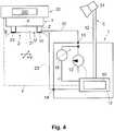
- the reference number 1denotes a vacuum device and the reference number 2 a patient interface connected to the vacuum device 1 in a schematic cross section.
- the patient interface 2is coupled to an ophthalmological application head 3 of an ophthalmological treatment device 30.
- the negative pressure device 1 and the patient interface 2together form an ophthalmological arrangement.
- the ophthalmological treatment device 30comprises a laser system 300 which is set up to generate laser pulses for the ophthalmological treatment of the patient's eye E and to focus them on and into the patient's eye E via the application head 3 and the patient interface 2.
- the patient interface 2rests with its underside U of the patient interface body 2 ′ on the cornea of the patient's eye E.
- the patient interface body 2 'of the patient interface 2has an, for example, cylindrical interior 21 which, in the application state, is located between the corneal surface of the patient's eye E and the application head 3 and can be filled, for example, with physiological saline solution as coupling fluid and optical transmission medium.
- a suction ringis arranged concentrically around the inner space 21, which in the application state also rests on the cornea of the patient's eye E and the inner space of which forms at least one negative pressure cavity 20, which is for example annular.
- a negative pressure or vacuumis generated in the negative pressure cavity 20, which thus fixes the patient interface 2 on the patient's eye E.
- the negative pressure device 1comprises a negative pressure generator 10, which is typically formed by a vacuum pump, and a negative pressure interface 13 which is fluidly coupled to the negative pressure generator 10.
- the vacuum generator 10 and the vacuum cavity 20 of the patient interface 2are fluidically coupled to one another via the vacuum connection line 22.
- one end of the vacuum connection line 22can be removed or is permanently fluidly coupled to the vacuum cavity 20 of the patient interface 2.
- the other end of the vacuum connecting line 22is fluidically coupled to the vacuum generator 10 via the vacuum interface 13.
- the negative pressure device 1also comprises a fluidic pressure sensor 11 and a pressure sensor interface 14 which is fluidically coupled to the pressure sensor 11.
- the pressure sensor 11 and the negative pressure cavity 20 of the patient interface 2are fluidically coupled to one another via the pressure sensor connection line 23, separately from the Vacuum connection line 22 on the side of the patient interface 2, the pressure sensor connection line 23 is coupled at one end to be removable or fixed fluidically to the vacuum cavity 20 of the patient interface 2.
- the other end of the pressure sensor connection line 23is fluidically coupled to the pressure sensor 11 via the pressure sensor interface 14.
- the vacuum connection line 22 and the pressure sensor connection line 23are each fluidically coupled separately at one end to the vacuum cavity 20, the fluidically separate coupling each extending over the entire fluidic path and in particular as far as the vacuum cavity 20.
- the negative pressure interface 13 and pressure sensor interface 14are, for example, as detachable fluidic connectors or couplers, e.g. B. fluid coupling sockets formed.
- the vacuum connection line 22 and the pressure sensor connection line 23each have corresponding fluidic coupling elements, for. B. fluidic connectors, which are provided for releasable coupling with the device-side negative pressure interface 13 or the device-side pressure sensor interface 14.
- the vacuum device 1also includes a control unit 12, which includes a processing unit 50 for controlling the function of the vacuum device 2.
- the processing unit 50is designed as an electronic circuit and comprises a logic circuit, for example an ASIC (Application Specific Integrated Circuit) or an FPGA (Field Programmable Gate Array), and / or one or more microprocessors with stored program code for controlling the microprocessors in such a way that they carry out the functions of the control unit 12 and of the movement detector 5 listed below, as described below.
- the negative pressure device 1is provided with a movement detector 5, which is set up to detect movements of the patient's eye E.
- the movement detector 5is set up to detect movements of the patient's eye E relative to a fixed observation axis, for example the optical axis z of a projection lens of the ophthalmological treatment device 30, both in directions of movement (x, y) which are in a direction of movement for observation or optical axis z normal x / y plane and correspond to a displacement of the patient's eye E (or a corresponding slipping of the patient interface 2) to the observation or optical axis z, as well as in directions of movement (z) that run along the observation or optical axis z and a change in distance to the patient interface 2 or to the application head 3 (or a lifting of the patient interface 2).
- a fixed observation axisfor example the optical axis z of a projection lens of the ophthalmological treatment device 30
- directions of movement (x, y)which are in a direction of movement for observation or optical axis z normal x / y plane and correspond to a displacement of the patient's
- the motion detector 5comprises one or more sensor devices 51 for imaging or beam-based detection methods, e.g. a video sensor for video recording of the patient's eye E and / or light transmitters and light detectors for beam-based OCT (Optical Coherence Tomography) systems or triangulation systems, etc.
- the video sensoris For example, designed as a CCD camera (Charge Coupled Device) and supplies video signals from the monitored patient's eye E.
- the sensor device 51is attached to the negative pressure device 1, for example by means of a carrier, or, fixed or removable, to the ophthalmic treatment device 30 , for example on the application head 3, attached or integrated.
- the measuring signalsare continuously transmitted from the sensor device 51 via a measuring signal line 52, for example a video signal line, to the processing unit 50, where they are evaluated for the detection of eye movements.
- the processing unit 50determines the in the Video signals continuously define video frames of the patient's eye E, local changes in reference features of the relevant patient's eye E, for example the pupil, iris and / or characteristic detail features of the iris, with respect to previously recorded and stored reference positions.
- repetitive spatial scans of the patient's eye Eare carried out, e.g.
- the processing unit 50recognizes and detects movements of the patient's eye E relative to the fixed observation or optical axis z.
- the beam-based OCT or triangulation methodin addition to lateral shifts in the x / y direction, also detects eye movements due to changes in the distance of the patient's eye E to the patient interface 2 or to the application head 3 in the z direction.
- movement detectors 5can be used to detect movements of the patient's eye E relative to the patient interface in the lateral x / y direction or with a change in distance in the z direction.
- the movement detector 5 or the processing unit 50indicates a detected eye movement when changes in the position of eye structures are detected that are above a defined tolerance threshold, for example above a defined distance limit d, e.g. d> 1mm, with respect to the observation axis z in x, y or z direction.
- Figure 2shows schematically part of a patient interface 2 together with a patient's eye E.
- the patient interface 2has a patient interface body 2 'with an annular negative pressure cavity 20 and an inner space 21.
- Two fluidic connecting pieces 22a, 23a, open separately into the negative pressure cavity 20.which are fluidically tightly connected in a basically known manner to the end of the negative pressure connection line 22 and the pressure sensor connection line 23 on the patient interface side, e.g. B. by gluing, ultrasonic welding, or by frictional engagement.
- the other ends of the fluidic negative pressure connection line 22 and pressure sensor connection line 23are coupled to the negative pressure device 1, for example by means of plug connectors which are coupled during operation to a corresponding patient interface coupler of the negative pressure device 1 in the form of a fluidic coupling socket.
- FIG. 3shows an embodiment of the negative pressure device 1, which is constructed in a basically similar manner to the negative pressure device 1 according to FIG Figure 1 , but additionally comprises a valve unit 16 which is operatively coupled to the control unit and activated by the control unit 12.
- the vacuum supply line 22is alternatively connected to the vacuum generator 10 (position shown) to build up and maintain the vacuum or to the environment for venting and reducing the vacuum in the vacuum cavity 20.
- the illustrated embodiment of the negative pressure device 11further comprises an optional flow sensor 17, which is arranged fluidically between the negative pressure interface 13 and the valve unit 16.
- the flow sensor 17is used to detect error states, in particular temporary or permanent leaks, which cause an increased air flow when air is sucked out of the negative pressure cavity 20.
- the second pressure sensor 15measures a (normal) negative pressure when the negative pressure generator 10 is in operation, but in comparison to the situation without pseudo-vacuum, there is no or only a reduced air flow through the flow sensor 17, which enables a detection of the pseudo vacuum.
- pressure sensor 11can be arranged directly on or in patient interface 2, pressure sensor connection line 23 being omitted and an electrical pressure sensor connection line being provided instead.
- the pressure sensor 11can be, for example, a miniaturized, disposable pressure sensor, which is, for example, permanently installed with the patient interface body 2 ', or the patient interface body 2' or the negative pressure cavity 20 and the pressure sensor 11 have a fluidic fluid that can be released non-destructively at least for the pressure sensor 11 Interface on.
- the vacuum interface 13 and the pressure sensor interface 14can also be located at the interface to the patient interface body 2 'instead of on a housing of the vacuum device 1.
- the vacuum connection line 22 and the pressure sensor connection line 23can be wholly or partially part of the vacuum device 1.
- the fluidic interfaces 13, 14can be implemented by means of separate fluidic couplers, for example separate fluidic connectors, or can be integrated into a common fluidic coupler or connector.
- the structure, in particular the fluidic structure, of the negative pressure device 1can also be modified and in particular comprise further components.
- the valve arrangement 16 according to Figure 3comprise further valves and enable further fluidic configurations.
- the vacuum generator 10is fluidically connected to the environment.
- the vacuum connection line 22, for example, together with the connected second pressure sensor 15can be fluidically closed or fluidically isolated.
- a vacuum reservoir with a volume in a range of, for example, one litercan be provided, which can be connected to the vacuum supply line 22 and / or the vacuum generator 10 by means of the valve arrangement.
- Such a vacuum reservoiris used in particular for fluidic buffering and can also be used in place of and in principle the same function as the vacuum generator for sucking off small amounts of air, for example in the event of a smaller and brief leakage of the vacuum cavity 20.
- the build-up of a vacuum in the optional vacuum reservoiris advantageously carried out by means of of the vacuum generator 10.
- Figure 4represents a further embodiment of an ophthalmological arrangement with a further embodiment of the negative pressure device 1 and a further embodiment of the patient interface 2 in a schematic functional representation and in the operatively coupled state.
- the negative pressure device 1 and the patient interface 2can be according to Figure 4 analogous to the illustration according to Figure 1 be constructed and have appropriate functionality.
- the fluidic pressure sensor 11is replaced by a contact pressure sensor 11 ′ which is arranged in the patient interface 2.
- the contact pressure sensor 11 'is for measuring the contract pressure between the Patient interface 2 and the patient's eye E and, for example, integrated in a ring shape into the side of a wall of the suction ring facing the patient's eye E.
- several isolated contact pressure sensorscan also be provided along the circumference of the suction ring or only a single isolated contact pressure sensor.
- the fluidic pressure sensor connection line 23 of Figure 1is replaced in this form by an electrical pressure sensor connection line 23 ', via which the contact pressure sensor 11' is functionally electrically coupled to the vacuum device 1. Accordingly, instead of the fluidic device-side pressure sensor interface 14 according to FIG Figure 1 an electrical device-side pressure sensor interface 14 ', e.g. B. in the form of an electrical connector, provided. A fluidic pressure sensor 11 according to Figure 1 can optionally be provided in addition.
- control unit 12 or the processing unit 50is connected via an (electrical) control line to the vacuum generator 10 and via (electrical) signal lines to the pressure sensors 11, 15 or the contact pressure sensors 11 '.
- the vacuum generator 10is controlled or put into operation by the control unit 12, so that the air originally present in the vacuum cavity 20 is at least partially sucked off.
- the curve marked with the reference numeral 4represents the amount of the negative pressure p , as measured by the pressure sensor 11, as a function of the time t for a correct fixation of the patient interface 2 on the patient's eye E.
- the air flow that occurs when the air is sucked out of the negative pressure cavity 20 out of the negative pressure cavity 20 in the direction of the negative pressure device 1 or the negative pressure generator 10also removes any liquid droplets, residues of sterile cover film etc. from the area of the coupling between the pressure sensor connection line 23 and the negative pressure cavity 20 .
- the curve 4 'in Figure 5shows schematically the pressure p measured by the pressure sensor 11 when a pseudo vacuum according to the type described above arises at a first error time point t f1 .
- the pressure sensor 11Due to the direct coupling of the pressure sensor 11 to the negative pressure cavity 20, which is independent of the negative pressure connecting line 22, the pressure sensor 11, on the other hand, measures the pressure effectively present in the negative pressure cavity 20. Correspondingly, the negative pressure measured by the pressure sensor 11 does not rise any further after the negative pressure connection line 20 has kinked, although the negative pressure generator 10 continues to operate.
- the negative pressure in the negative pressure cavity 20remains essentially constant after the occurrence of the pseudo-vacuum (at too low a level) or falls again due to elasticity and / or possibly existing leakages, so that pressure equalization with the environment takes place.
- the curve 4 "in Figure 5represents the pressure measured by the pressure sensor 11 in the event that the negative pressure in the negative pressure cavity 20 (after the negative pressure has initially been built up correctly and the patient interface 2 has been correctly fixed on the patient's eye E) at a second error time t f2 during stationary operation falls off.
- Thisis the case, for example, when the patient interface 2 is briefly and partially detached from the patient's eye E, which in unfavorable cases, e.g. B. due to a required movement of the patient interface by the ophthalmologist or a movement of the patient himself.
- this pressure dropcan be detected by the pressure sensor 15 and the negative pressure generator 10 can generate the correct negative pressure restore at least in the event of a brief leak. If, however, the vacuum connecting line 22 itself is kinked or not open for other reasons, the drop in the vacuum is not detected by the pressure sensor 15. In the case of an only partially continuous vacuum connection line 22, at least the control delay increases when regulating the pressure drop, so that a secure fixation of the patient interface 2 on the patient's eye E is also no longer given or at least cannot be guaranteed.
- the curve 4 '"in Figure 5represents the case that (after an initially correct build-up of the negative pressure and a correct fixation of the patient interface 2 on the patient's eye E) the negative pressure slowly drops at a third error time t f3 (compared to the curve shown in curve 4 ′′), which can be caused, for example, by a slight leakage or leakage of a fluidic connector.
- the curves 4 * and 4 ** in Figure 5represent cases in which (after an initially correct build-up of the negative pressure and a correct fixation of the patient interface 2 on the patient's eye E) the negative pressure drops briefly and temporarily at a fourth error time t f4 , which z. B. by a temporary blockage of the vacuum connection line 22 - but also the pressure sensor connection line 23 - can be caused.
- the set negative pressure p nom corresponding to the intended operating stateis built up again within a time period which is before (or within) a predetermined maximum time period t max .
- the set negative pressure p nomis only reached again after the maximum time period t max has elapsed.
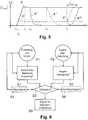
- Figure 6schematically illustrates processes P1, P2 and steps S1, S2, S3, S4, S5 for monitoring the ophthalmological patient interface 2.
- the pressure (negative pressure) in the negative pressure cavity 20is determined continuously or quasi-continuously.
- the pressure in process P1is determined by pressure sensor 11, alternatively by one or more contact pressure sensors 11 ', optionally in addition by one or more (redundant) contact pressure sensors 11 ′, and optionally in addition by the (redundant) pressure sensor 15.
- step S1the processing unit 50 determines, based on the pressure values determined in process P1, whether there is a faulty fluidic coupling of the patient interface 2 or the vacuum cavity 20.
- the measured pressureis continuously or quasi-continuously compared with at least one negative limit pressure p limit .
- This limit pressure p limitis typically lower in terms of amount than the nominal negative pressure p nom and can, for. B. by the amount of the nominal negative pressure p nom minus a safety value determined by tolerances, measurement uncertainty, etc. take place.
- the limit pressure p limitcan be continuously adapted in accordance with the pressure curve that results in correct operation. A fault is then assumed if the pressure falls below the limit pressure p limit .
- the measured pressureis evaluated continuously or quasi-continuously with regard to a decrease or decrease in the negative pressure.
- Numerous fundamentally known methods of signal processing and / or statisticscan be used for this, for example determination and Evaluation of the slope and / or further characteristic values of a function formed by interpolation of measured values.
- the vacuum device 1also includes the optional second pressure sensor 15, alternatively or additionally, a faulty fluidic coupling of the patient interface 2 is detected by comparing or evaluating the pressures determined by the pressure sensor 11 and the second pressure sensor 15.
- the pressures measured by the pressure sensor 11 and the second pressure sensor 15are essentially the same at least in the steady-state operating state and the sensors 11, 15 are therefore redundant.
- the detection of a faulty or insufficient fluidic coupling of the patient interface 2can include the detection of a deviation between the pressures determined by the pressure sensor 11 and the second pressure sensor 15. The deviation can be determined by means of fundamentally known signal processing and / or statistical methods and e.g.
- determining a faulty or inadequate couplingcan include, for example, determining and evaluating a correlation of the pressures determined by pressure sensor 11 and second pressure sensor 15 as a function of time t.
- control device 12 or the processing unit 50when detecting a faulty fluidic coupling of the patient interface 2, takes into account the period of time during which a pressure drop is detected in order to avoid an ophthalmological laser treatment unnecessarily due to a brief, interrupt the temporary pressure drop, which does not cause any disruptive detachment or displacement of the patient interface 2 from or relative to the patient's eye E.
- a short-term, temporary pressure drop that is again above the required limit pressure p limit within a specified maximum time period t maxis not treated as a faulty fluidic coupling of the patient interface 2, at least not if such short-term, temporary pressure drops are not repeated with a frequency that transcends boundaries (Oscillation behavior).
- the pressure sensor 11reacts faster than the second vacuum sensor 15, particularly during the build-up of the negative pressure in the negative pressure cavity 20 and during venting, to changes in pressure in the negative pressure cavity 20 This results from the fact that at the same time a displacement of air volume takes place via the vacuum connection line 22, while the pressure sensor connection line 23 is fluidically closed by the pressure sensor 11.
- a joint evaluation of the pressures determined by the pressure sensor 11 and the second pressure sensor 15results in the advantage that the control device 12 or the processing unit 50 can also detect further error states, for example a pseudo vacuum in the pressure sensor connection line 23 or defects in the pressure sensors 11, 15 of their electrical contacting and / or downstream components.
- process P2the continuous or quasi-continuous (video) monitoring of the patient's eye E takes place by the sensor device (s) 51 of the movement detector 5.
- step S2the processing unit 50 detects movements of the patient's eye E based on the monitoring carried out in process P2 (video monitoring, video acquisition, OCT measurement, triangulation, etc.) or on the measurement signals supplied by the sensor device (s) 51 in process P2 (e.g. video signals).
- step S3the processing unit 50 examines whether a detected movement of the patient's eye E is present at the same time as a detected faulty fluidic coupling of the patient interface 2. If this is not the case, the ongoing determination of the pressure in the negative pressure cavity 20 is continued in process P1 and the ongoing monitoring of the patient's eye E is continued in process P2 without the ophthalmological treatment being interrupted or canceled by the ophthalmic treatment device 30.
- the processing unit 50generates a warning signal which indicates that a faulty fluidic coupling of the patient interface 2 has been detected.
- the control unit 12comprises an alarm device or is connected to an alarm device (not shown) which is set up to generate an optical and / or acoustic alarm based on the warning signal.
- the processing unit 50generates a correction signal for the ophthalmic treatment device 30 or the laser system 300 after the eye has been detected if no faulty fluidic coupling of the negative pressure cavity 20 is detected.
- the correction signalenables the ophthalmological treatment device 30 or the laser system 300 to realign or reposition the laser beam or its focus, taking into account the detected eye movement and the target position (according to control data of the ophthalmic treatment) and the ophthalmic To continue treatment if no faulty fluidic coupling of the negative pressure cavity 20 is detected.
- the correction signalincludes an indication of the detected eye movement, for example the current (actual) position of the patient's eye E or a displacement vector that sets the movement of the patient's eye E, starting from its starting position, before the detected eye movement, to its actual position, after the detected one Eye movement, defined and enables the ophthalmological treatment device 30 or the laser system 300 to correct with realignment of the laser beam or repositioning of its focus.
- an indication of the detected eye movementfor example the current (actual) position of the patient's eye E or a displacement vector that sets the movement of the patient's eye E, starting from its starting position, before the detected eye movement, to its actual position, after the detected one Eye movement, defined and enables the ophthalmological treatment device 30 or the laser system 300 to correct with realignment of the laser beam or repositioning of its focus.
- the processing unit 50If a faulty fluidic coupling of the patient interface 2 and an eye movement of the patient are detected at the same time, the processing unit 50 generates a control signal s in step S5 to abort the ophthalmological treatment which is carried out by the ophthalmic treatment device 30.
- the control signal sis fed from the control unit 12 or the processing unit 50 via a signal line to the ophthalmological treatment device 30.
- the control unit 12 or the processing unit 50is connected to the ophthalmological treatment device 30 or is arranged in the ophthalmological treatment device 30, for example in the application head 3.
- the ophthalmological treatmentis interrupted or canceled due to the incoming control signal, for example the laser system 300 is switched off and / or the laser beam is interrupted by moving a screen or a shutter.
- the control unit 12 or the processing unit 50generates an alarm signal, as was described above in connection with the warning signal from step S4.
Landscapes
- Health & Medical Sciences (AREA)
- Ophthalmology & Optometry (AREA)
- Life Sciences & Earth Sciences (AREA)
- Physics & Mathematics (AREA)
- Engineering & Computer Science (AREA)
- Optics & Photonics (AREA)
- Surgery (AREA)
- Public Health (AREA)
- Heart & Thoracic Surgery (AREA)
- Veterinary Medicine (AREA)
- Biomedical Technology (AREA)
- Animal Behavior & Ethology (AREA)
- General Health & Medical Sciences (AREA)
- Nuclear Medicine, Radiotherapy & Molecular Imaging (AREA)
- Vascular Medicine (AREA)
- Human Computer Interaction (AREA)
- Biophysics (AREA)
- Medical Informatics (AREA)
- Molecular Biology (AREA)
- Eye Examination Apparatus (AREA)
Description
Translated fromGermanDie vorliegende Erfindung betrifft eine Unterdruckvorrichtung und ein Verfahren zum Überwachen eines ophthalmologischen Patienteninterfaces. Die vorliegende Erfindung betrifft insbesondere eine Unterdruckvorrichtung zum Fixieren eines ophthalmologischen Patienteninterfaces auf einem Patientenauge und ein Verfahren zum Überwachen des ophthalmologischen Patienteninterfaces.The present invention relates to a negative pressure device and a method for monitoring an ophthalmological patient interface. The present invention relates in particular to a negative pressure device for fixing an ophthalmological patient interface on a patient's eye and a method for monitoring the ophthalmological patient interface.
Zur Behandlung und/oder Diagnose von Augengewebe ist der Einsatz von Strahlungsgeneratoren, insbesondere Lasern, bekannt. Entsprechende Vorrichtungen wie ophthalmologischen Lasereinrichtungen weisen beispielsweise ein Basisgerät mit einer Laser-Lichtquelle zur Erzeugung von Laserpulsen, beispielsweise Femtosekundenlaserpulse, sowie einen Applikationskopf mit einem Projektionsobjektiv auf, der zur Behandlung mit dem Patientenauge gekoppelt wird. Der Applikationskopf kann, beispielsweise über einen Gelenkarm, beweglich mit dem Basisgerät verbunden sein, wobei der Gelenkarm zugleich der optischen Strahlführung von der Laser-Lichtquelle zum Applikationskopf dienen kann. Eine entsprechende Anordnung ist beispielsweise in der
Die mechanische und optische Kopplung des Applikationskopfes an das Patientenauge, beispielsweise an die Hornhaut und/oder die Sklera des Patientenauges, erfolgt über ein Patienteninterface, wobei das Patienteninterface einen transparenten Kontaktkörper umfassen kann, durch welchen die aus dem Projektionsobjektiv austretenden Laserpulse fokussiert auf oder ins Auge geleitet werden und welcher durch mechanischen Kontakt mit der Hornhaut diese bezüglich des Patienteninterfaces und des Projektionsobjektives fixiert. Alternativ zur Kopplung mittels eines Kontaktkörpers kann eine Flüssigkeitskopplung vorgesehen werden, wobei sich zwischen Hornhaut und Projektionsobjektiv eine Koppelflüssigkeit, beispielsweise physiologische Kochsalzlösung, befindet. Entsprechende Patienteninterfaces sind beispielsweise aus der
Die Kopplung des Patienteninterfaces an das Patientenauge kann mittels Vakuum und einer Unterdruckkavität des Patienteninterfaces erfolgen. Die Unterdruckkavität ist typischerweise ein auf die Hornhaut aufgesetzter Saugring. Die meisten Saugringe haben zwei Dichtlippen. Die Lippen können auf der Sklera, der Sklera und der Hornhaut oder nur auf der Hornhaut angebracht sein. Weiterhin gibt es Varianten, die nur einen Ring besitzen und über dem ganzen Auge ein Vakuum erzeugen, oder Varianten, die aus mehreren Saugkammern/Saugnäpfen bestehen. Der Saugring ist die gebräuchlichste Methode der Befestigung, es gibt jedoch auch andere bekannte Lösungen. In jedem Fall erfolgt die Kopplung an das Patientenauge durch ein Vakuum bzw. ein Unterdruck in mindestens einer Unterdruckkavität des Patienteninterfaces, wobei die Unterdruckkavität entlang ihres Umfangs dichtend auf dem Patientenauge aufliegt und das Patienteninterface so fluidisch dichtend an das Patientenauge koppelt und gegen die Umwelt abdichtet. Die Erzeugung des Unterdrucks kann durch einen Unterdruckgenerator, insbesondere eine Vakuumpumpe bzw. Unterdruckpumpe, erfolgen. Die Kopplung des Patienteninterfaces an den Applikationskopf erfolgt bei bekannten Systemen beispielsweise mittels Schraubverbindung, Bajonettverschlüssen oder Vakuumkupplungen.The coupling of the patient interface to the patient's eye can take place by means of a vacuum and a negative pressure cavity of the patient interface. The negative pressure cavity is typically a suction ring placed on the cornea. Most suction rings have two sealing lips. The lips can be attached to the sclera, sclera and cornea, or just on the cornea. There are also variants that have only one ring and create a vacuum over the entire eye, or variants that consist of several suction chambers / suction cups. The suction ring is the most common method of attachment, but there are other known solutions. In any case, the coupling to the patient's eye takes place through a vacuum or a negative pressure in at least one negative pressure cavity of the patient interface, the negative pressure cavity sealingly rests on the patient's eye along its circumference and thus coupling the patient interface to the patient's eye in a fluidic sealing manner and sealing it off from the environment. The vacuum can be generated by a vacuum generator, in particular a vacuum pump or vacuum pump. In known systems, the patient interface is coupled to the application head, for example, by means of screw connections, bayonet locks or vacuum couplings.
Die
Die
Die
Die
Es ist eine Aufgabe der vorliegenden Erfindung eine Unterdruckvorrichtung zum Fixieren eines ophthalmologischen Patienteninterfaces auf einem Patientenauge und ein Verfahren zum Überwachen des ophthalmologischen Patienteninterfaces vorzuschlagen, welche Unterdruckvorrichtung und welches Verfahren, zumindest einige Nachteile der bekannten Systeme nicht aufweisen. Es ist insbesondere eine Aufgabe der vorliegenden Erfindung eine Unterdruckvorrichtung und ein Verfahren zum Überwachen des ophthalmologischen Patienteninterfaces vorzuschlagen, welche unnötige Unterbrechungen von Laserbehandlungen möglichst vermeiden.It is an object of the present invention to propose a vacuum device for fixing an ophthalmic patient interface on a patient's eye and a method for monitoring the ophthalmic patient interface, which vacuum device and which method do not have at least some disadvantages of the known systems. In particular, it is an object of the present invention to propose a vacuum device and a method for monitoring the ophthalmological patient interface, which avoid unnecessary interruptions of laser treatments as far as possible.
Gemäss der vorliegenden Erfindung werden diese Ziele durch die Merkmale der unabhängigen Ansprüche erreicht. Weitere vorteilhafte Ausführungsformen gehen ausserdem aus den abhängigen Ansprüchen und der Beschreibung hervor.According to the present invention, these goals are achieved by the features of the independent claims. Further advantageous embodiments are also evident from the dependent claims and the description.
Eine Unterdruckvorrichtung zum Fixieren eines ophthalmologischen Patienteninterfaces auf einem Patientenauge umfasst einen Unterdruckgenerator und eine Unterdruckschnittstelle zur fluidischen Kopplung des Unterdruckgenerators an eine Unterdruckkavität des Patienteninterfaces.A negative pressure device for fixing an ophthalmological patient interface on a patient's eye comprises a negative pressure generator and a negative pressure interface for fluidically coupling the negative pressure generator to a negative pressure cavity of the patient interface.
Die oben genannten Ziele werden durch die vorliegende Erfindung insbesondere dadurch erreicht, dass die Unterdruckvorrichtung einen an das Patienteninterface fluidisch ankoppelbaren internen Drucksensor und/oder eine Druckmessschnittstelle zur signaltechnischen Ankopplung eines externen Drucksensors des Patienteninterfaces umfasst, und zudem einen Bewegungsdetektor aufweist, der eingerichtet ist, Bewegungen des Patientenauges zu detektieren. Die Unterdruckvorrichtung umfasst überdies eine Steuereinheit, die eingerichtet ist, aufgrund des vom angekoppelten Drucksensor ermittelten Drucks eine fehlerhafte fluidische Kopplung der Unterdruckkavität zu detektieren, und ein Steuersignal zum Abbrechen einer durch eine ophthalmologische Behandlungsvorrichtung durchgeführten ophthalmogischen Behandlung zu erzeugen, wenn gleichzeitig mit der detektierten fehlerhaften fluidischen Kopplung der Unterdruckkavität vom Bewegungsdetektor eine Augenbewegung detektiert wird.The above-mentioned objectives are achieved by the present invention in particular in that the vacuum device has an internal pressure sensor that can be fluidly coupled to the patient interface and / or a pressure measurement interface for signaling coupling of an external pressure sensor of the patient interface comprises, and also has a motion detector which is set up to detect movements of the patient's eye. The negative pressure device also comprises a control unit which is set up to detect a faulty fluidic coupling of the negative pressure cavity on the basis of the pressure determined by the coupled pressure sensor, and to generate a control signal for canceling an ophthalmic treatment carried out by an ophthalmic treatment device, if simultaneously with the detected faulty fluidic Coupling of the negative pressure cavity from the motion detector an eye movement is detected.
In einer Ausführungsvariante ist die Steuereinheit eingerichtet, ohne Unterbruch der ophthalmogischen Behandlung ein Warnsignal zu erzeugen, wenn während einer detektierten fehlerhaften fluidischen Kopplung der Unterdruckkavität keine Augenbewegung detektiert wird.In one embodiment variant, the control unit is set up to generate a warning signal without interrupting the ophthalmological treatment if no eye movement is detected during a detected faulty fluidic coupling of the negative pressure cavity.
In einer Ausführungsvariante umfasst der Bewegungsdetektor einen Videosensor und eine mit dem Videosensor verbundene Verarbeitungseinheit, welche eingerichtet ist, die Augenbewegungen aufgrund von vom Videosensor gelieferten Videosignalen zu detektieren.In one embodiment variant, the motion detector comprises a video sensor and a processing unit connected to the video sensor, which is set up to detect the eye movements on the basis of video signals supplied by the video sensor.
In einer Ausführungsvariante ist der Bewegungsdetektor eingerichtet, Bewegungen des Patientenauges zu detektieren, welche das Patientenauge relativ zu einer starren Beobachtungsachse bewegen.In one embodiment variant, the movement detector is set up to detect movements of the patient's eye which move the patient's eye relative to a rigid observation axis.
In einer Ausführungsvariante ist die Steuereinheit eingerichtet, das Steuersignal zum Abbrechen der ophthalmogischen Behandlung zu erzeugen, wenn vom Bewegungsdetektor eine Augenbewegung detektiert wird, die über einem definierten Toleranzschwellwert liegt.In one embodiment variant, the control unit is set up to generate the control signal for canceling the ophthalmological treatment when from Movement detector an eye movement is detected that is above a defined tolerance threshold.
In einer Ausführungsvariante umfasst die Unterdruckvorrichtung eine mit dem internen Drucksensor fluidisch verbundene Drucksensorschnittstelle, die eingerichtet ist, den internen Drucksensor separat zu der Unterdruckschnittstelle fluidisch mit dem Patienteninterface zu koppeln.In one embodiment variant, the negative pressure device comprises a pressure sensor interface that is fluidically connected to the internal pressure sensor and is set up to fluidically couple the internal pressure sensor to the patient interface separately from the negative pressure interface.
In einer Ausführungsvariante ist die Druckmessschnittstelle eingerichtet zur signaltechnischen Ankopplung eines am Patienteninterface angeordneten externen Kontaktdrucksensors.In one embodiment variant, the pressure measurement interface is set up for the signaling connection of an external contact pressure sensor arranged on the patient interface.
In einer Ausführungsvariante ist die Steuereinheit eingerichtet, die fehlerhafte fluidische Kopplung der Unterdruckkavität durch Detektion einer Abweichung zwischen dem mittels des angekoppelten Drucksensors ermittelten Drucks und einem Referenzdruck, und/oder durch Detektion eines Abfalls des Drucks in Funktion der Zeit, zu detektieren.In one embodiment variant, the control unit is set up to detect the faulty fluidic coupling of the negative pressure cavity by detecting a deviation between the pressure determined by the coupled pressure sensor and a reference pressure, and / or by detecting a drop in pressure as a function of time.
In einer Ausführungsvariante umfasst die Unterdruckvorrichtung einen mit der Unterdruckschnittstelle fluidisch gekoppelten und mit der Steuereinheit verbundenen zweiten Drucksensor, und die Steuereinheit ist eigerichtet, die fehlerhafte fluidische Kopplung der Unterdruckkavität durch Vergleichen des ermittelten Drucks mit einem vom zweiten Drucksensor ermittelten zweiten Druck zu detektieren.In one embodiment variant, the vacuum device comprises a second pressure sensor fluidically coupled to the vacuum interface and connected to the control unit, and the control unit is designed to detect the faulty fluidic coupling of the vacuum cavity by comparing the determined pressure with a second pressure determined by the second pressure sensor.
In einer Ausführungsvariante umfasst der Bewegungsdetektor eine Sensorvorrichtung, welche eingerichtet ist, die Augenbewegungen aufgrund von Distanzveränderungen des Patientenauges relativ zum Patienteninterface zu detektieren.In one embodiment variant, the movement detector comprises a sensor device which is set up to detect the eye movements based on changes in the distance of the patient's eye relative to the patient interface.
In einer Ausführungsvariante ist die Steuereinheit eingerichtet, aufgrund einer detektierten Augenbewegung ein Korrektursignal zur Repositionierung und Fortführung der ophthalmogischen Behandlung zu erzeugen, wenn eine Beendigung der Augenbewegung und keine fehlerhafte fluidische Kopplung der Unterdruckkavität detektiert wird.In one embodiment variant, the control unit is set up to generate a correction signal for repositioning and continuing the ophthalmological treatment on the basis of a detected eye movement, if an end of the eye movement and no faulty fluidic coupling of the negative pressure cavity is detected.
Neben der Unterdruckvorrichtung zum Fixieren eines ophthalmologischen Patienteninterfaces auf einem Patientenauge betrifft die vorliegende Anmeldung auch ein Verfahren zum Überwachen des ophthalmologischen Patienteninterfaces, das mittels eines, durch den Unterdruckgenerator in einer Unterdruckkavität des Patienteninterfaces hergestellten, Unterdrucks auf dem Patientenauge fixiert ist. Das Verfahren umfasst: Ermitteln eines Drucks in der Unterdruckkavität mittels eines fluidisch an das Patienteninterface angekoppelten Drucksensors und/oder eines Kontaktdrucksensors des Patienteninterfaces; Detektieren von Bewegungen des Patientenauges mittels eines Bewegungsdetektors; Detektieren durch eine Steuereinheit einer fehlerhaften fluidischen Kopplung der Unterdruckkavität an den Unterdruckgenerator aufgrund des ermittelten Drucks; und Erzeugen durch die Steuereinheit eines Steuersignals zum Abbrechen einer durch eine ophthalmologische Behandlungsvorrichtung durchgeführten ophthalmogischen Behandlung, wenn gleichzeitig mit der detektierten fehlerhaften fluidischen Kopplung der Unterdruckkavität vom Bewegungsdetektor eine Augenbewegung detektiert wird.In addition to the negative pressure device for fixing an ophthalmic patient interface on a patient's eye, the present application also relates to a method for monitoring the ophthalmic patient interface, which is fixed on the patient's eye by means of a negative pressure produced by the negative pressure generator in a negative pressure cavity of the patient interface. The method comprises: determining a pressure in the negative pressure cavity by means of a pressure sensor fluidly coupled to the patient interface and / or a contact pressure sensor of the patient interface; Detecting movements of the patient's eye by means of a movement detector; Detection by a control unit of a faulty fluidic coupling of the negative pressure cavity to the negative pressure generator based on the determined pressure; and generating by the control unit a control signal for canceling an ophthalmological treatment carried out by an ophthalmological treatment device if an eye movement is detected by the movement detector at the same time as the faulty fluidic coupling of the negative pressure cavity is detected.
In einer Ausführungsvariante erzeugt die Steuereinheit, ohne Unterbruch der ophthalmogischen Behandlung, ein Warnsignal, wenn während einer detektierten fehlerhaften fluidischen Kopplung der Unterdruckkavität keine Augenbewegung detektiert wird.In one embodiment variant, the control unit generates a warning signal, without interrupting the ophthalmological treatment, if no eye movement is detected during a detected faulty fluidic coupling of the negative pressure cavity.
In einer Ausführungsvariante erfolgt eine Videoerfassung des Patientenauges durch einen Videosensor, und die Augenbewegungen werden durch die Steuereinheit aufgrund der Videoerfassung detektiert.In one embodiment, video recording of the patient's eye is carried out by a video sensor, and the eye movements are detected by the control unit on the basis of the video recording.
In einer Ausführungsvariante erzeugt die Steuereinheit das Steuersignal zum Abbrechen der ophthalmogischen Behandlung, wenn vom Bewegungsdetektor eine Augenbewegung detektiert wird, die über einem definierten Toleranzschwellwert liegt.In one embodiment variant, the control unit generates the control signal for canceling the ophthalmological treatment when the movement detector detects an eye movement that is above a defined tolerance threshold value.
Die vorliegende Anmeldung betrifft auch eine ophthalmologische Behandlungsvorrichtung, die ein Lasersystem zur ophthalmologischen Behandlung eines Patientenauges, einen Applikationskopf, und ein Patienteninterface zum Anbringen des Applikationskopfes auf dem Patientenauge umfasst. Die ophthalmologische Behandlungsvorrichtung umfasst überdies die obenstehend angeführte Unterdruckvorrichtung zum Fixieren des ophthalmologischen Patienteninterfaces auf dem Patientenauge.The present application also relates to an ophthalmological treatment device which comprises a laser system for ophthalmological treatment of a patient's eye, an application head, and a patient interface for attaching the application head to the patient's eye. The ophthalmological treatment device also comprises the above-mentioned vacuum device for fixing the ophthalmic patient interface on the patient's eye.
Nachfolgend wird eine Ausführung der vorliegenden Erfindung anhand eines Beispieles beschrieben. Das Beispiel der Ausführung wird durch die folgenden beigelegten Figuren illustriert:
- Figur 1:
- zeigt ein Blockdiagramm einer ophthalmologischen Anordnung mit einer Unterdruckvorrichtung und einem damit fluidisch gekoppelten Patienteninterface.
- Figur 2:
- zeigt schematisch im Querschnitt eine Ausführungsform eines an einem Patientenauge fixierten Patienteninterfaces, das fluidisch mit einer Unterdruckvorrichtung gekoppelt ist.
- Figur 3:
- zeigt ein Blockdiagramm einer Unterdruckvorrichtung mit einem Unterdruckgenerator und einer Unterdruckschnittstelle zur fluidischen Kopplung des Unterdruckgenerators an eine Unterdruckkavität eines Patienteninterfaces.
- Figur 4:
- zeigt ein Blockdiagramm einer weiteren ophthalmologischen Anordnung mit einer Unterdruckvorrichtung und einem damit fluidisch gekoppelten Patienteninterface.
- Figur 5:
- zeigt verschiedene Druckverläufe in Funktion der Zeit.
- Figur 6:
- zeigt ein Flussdiagramm, das Prozesse und Schritte zum Überwachen eines ophthalmologischen Patienteninterfaces illustriert.
- Figure 1:
- shows a block diagram of an ophthalmological arrangement with a negative pressure device and a patient interface fluidically coupled therewith.
- Figure 2:
- shows schematically in cross section an embodiment of a patient interface fixed to a patient's eye, which is fluidically coupled to a vacuum device.
- Figure 3:
- shows a block diagram of a negative pressure device with a negative pressure generator and a negative pressure interface for the fluidic coupling of the negative pressure generator to a negative pressure cavity of a patient interface.
- Figure 4:
- shows a block diagram of a further ophthalmological arrangement with a negative pressure device and a patient interface fluidically coupled therewith.
- Figure 5:
- shows different pressure curves as a function of time.
- Figure 6:
- Figure 12 is a flow diagram illustrating processes and steps for monitoring an ophthalmic patient interface.
In der
Im Anwendungszustand liegt das Patienteninterface 2 mit seiner Unterseite U des Patienteninterfacekörpers 2' auf der Hornhaut des Patientenauges E auf. Der Patienteninterfacekörper 2' des Patienteninterfaces 2 weist einen zum Beispiel zylindrischen Innenraum 21 auf, welcher sich im Anwendungszustand zwischen der Hornhautoberfläche des Patientenauges E und dem Applikationskopf 3 befindet und beispielsweise mit physiologischer Kochsalzlösung als Koppelflüssigkeit und optisches Übertragungsmedium gefüllt sein kann. Konzentrisch um den Innenraum 21 ist ein Saugring angeordnet, welcher im Anwendungszustand ebenfalls auf der Hornhaut des Patientenauges E aufliegt und dessen Innenraum mindestens eine Unterdruckkavität 20 bildet, die beispielsweise ringförmige ausgestaltet ist. Zur Kopplung des Patienteninterfaces 2 bzw. des Patienteninterfacekörpers 2' an das Patientenauge E wird in der Unterdruckkavität 20 ein Unterdruck bzw. Vakuum erzeugt, welches so das Patienteninterface 2 auf dem Patientenauge E fixiert.In the application state, the
Die Unterdruckvorrichtung 1 umfasst einen Unterdruckgenerator 10, der typischerweise durch eine Vakuumpumpe gebildet wird, sowie eine Unterdruckschnittstelle 13, die fluidisch mit dem Unterdruckgenerator 10 gekoppelt ist. Der Unterdruckgenerator 10 und die Unterdruckkavität 20 des Patienteninterfaces 2 sind über die Unterdruckverbindungsleitung 22 fluidisch miteinander gekoppelt. Auf der Seite des Patienteninterfaces 2 ist die Unterdruckverbindungsleitung 22 mit einem Ende entfernbar oder fest fluidisch mit der Unterdruckkavität 20 des Patienteninterfaces 2 gekoppelt. Auf der Seite der Unterdruckvorrichtung 1 ist die Unterdruckverbindungsleitung 22 mit ihrem anderen Ende über die Unterdruckschnittstelle 13 fluidisch mit dem Unterdruckgenerator 10 gekoppelt.The
Die Unterdruckvorrichtung 1 umfasst zudem einen fluidischen Drucksensor 11 und eine Drucksensorschnittstelle 14, die fluidisch mit dem Drucksensor 11 gekoppelt ist. Der Drucksensor 11 und die Unterdruckkavität 20 des Patienteninterfaces 2 sind über die Drucksensorverbindungsleitung 23 fluidisch miteinander gekoppelt, separat von der Unterdruckverbindungsleitung 22. Auf der Seite des Patienteninterfaces 2 ist die Drucksensorverbindungsleitung 23 mit einem Ende entfernbar oder fest fluidisch mit der Unterdruckkavität 20 des Patienteninterfaces 2 gekoppelt. Auf der Seite der Unterdruckvorrichtung 1 ist die Drucksensorverbindungsleitung 23 mit ihrem anderen Ende über die Drucksensorschnittstelle 14 fluidisch mit dem Drucksensor 11 gekoppelt.The
Die Unterdruckverbindungsleitung 22 und die Drucksensorverbindungsleitung 23 sind mit einem Ende jeweils separat fluidisch an die Unterdruckkavität 20 gekoppelt, wobei sich die fluidisch separate Kopplung jeweils auf den gesamten fluidischen Pfad und insbesondere bis zur Unterdruckkavität 20 erstreckt.The
Die Unterdruckschnittstelle 13 und Drucksensorschnittstelle 14 sind beispielsweise als lösbare fluidische Steckverbinder oder Koppler, z. B. fluidische Kupplungsbuchsen, ausgebildet. Die Unterdruckverbindungsleitung 22 und die Drucksensorverbindungsleitung 23 weisen jeweils entsprechende fluidische Koppelelemente auf, z. B. fluidische Steckverbinder, die zur lösbaren Kopplung mit der vorrichtungsseitigen Unterdruckschnittstelle 13 bzw. der vorrichtungsseitigen Drucksensorschnittstelle 14 vorgesehen sind.The
Die Unterdruckvorrichtung 1 umfasst überdies eine Steuereinheit 12, welche eine Verarbeitungseinheit 50 zur Steuerung der Funktion der Unterdruckvorrichtung 2 umfasst. Die Verarbeitungseinheit 50 ist als elektronische Schaltung ausgebildet und umfasst eine Logikschaltung, z.B. ein ASIC (Application Specific Integrated Circuit) oder ein FPGA (Field Programmable Gate Array), und/oder einen oder mehrere Mikroprozessoren mit gespeichertem Programmcode zur Steuerung der Mikroprozessoren derart, dass diese die nachfolgend beschriebenen Funktionen der Steuereinheit 12 und des nachfolgend angeführten Bewegungsdetektors 5 ausführen. Wie in den
Über die Ventileinheit 16 wird die Unterdruckversorgungsleitung 22 alternativ mit dem Unterdruckgenerator 10 (dargestellte Stellung) zu Aufbau und Aufrechterhaltung des Unterdrucks oder mit der Umgebung zur Entlüftung und zum Abbau des Unterdrucks in der Unterdruckkavität 20 verbunden.Via the
Die in
Die in
Die Unterdruckschnittstelle 13 sowie die Drucksensorschnittstelle 14 können sich anstatt an einem Gehäuse der Unterdruckvorrichtung 1 auch an der Schnittstelle zum Patienteninterfacekörper 2' befinden. In diesem Fall können die Unterdruckverbindungsleitung 22 und die Drucksensorverbindungsleitung 23 ganz oder teilweise Teil der Unterdruckeinrichtung 1 sein. Die fluidischen Schnittstellen 13, 14 können mittels separater fluidischer Koppler, beispielsweise separater fluidischer Steckverbinder, realisiert werden, oder in einen gemeinsamen fluidischen Koppler oder Steckverbinder integriert sein.The
Der Aufbau, insbesondere der fluidische Aufbau, der Unterdruckvorrichtung 1, kann ferner modifiziert werden und insbesondere weitere Komponenten umfassen. So kann die Ventilanordnung 16 gemäss
In der Ausführungsform gemäß
Die fluidische Drucksensorverbindungsleitung 23 der
Wie in den
Zur Kopplung des Patienteninterfaces 2 an das Patientenauge E wird der Unterdruckgenerator 10 durch die Steuereinheit 12 angesteuert bzw. in Betrieb gesetzt, so dass die in der Unterdruckkavität 20 ursprünglich vorhandene Luft zumindest teilweise abgesaugt wird. Der funktionell separat mit der Unterdruckkavität 20 gekoppelte Drucksensor 11 misst den effektiv in der Unterdruckkavität 20 vorhandenen Druck unabhängig von der Unterdruckverbindungsleitung 22 (alternativ messen ein oder mehrere Kontaktdrucksensoren 11' den Kontraktdruck).To couple the
In
In der zum Zeitpunktt0 beginnenden Absaugphase wird in der Unterdruckkavität 20 vorhandene Luft durch den Unterdruckgenerator 10 durch die Unterdruckverbindungsleitung 22 abgesaugt, wodurch der Unterdruck ansteigt. Bei einem dem vorgesehenen Betriebszustand entsprechenden Sollunterdruck von z. B.pnom = -400mbar schaltet die Steuereinheit 12 zum Zeitpunktt1 in bekannter Weise in einen stationären Haltebetrieb um, bei welchem der Unterdruck in der Unterdruckkavität 20 im Wesentlichen konstant gehalten wird. Dieser Zustand bleibt erhalten, bis gewollt ein Druckausgleich mit der Umgebung hergestellt und so das Patienteninterface 2 von der Hornhaut des Patientenauges E gelöst wird.In the suction phase beginning at timet0 , air present in the
Der beim Absaugen der Luft aus dem Unterdruckkavität 20 entstehende Luftstrom aus der Unterdruckkavität 20 heraus in Richtung der Unterdruckvorrichtung 1 bzw. des Unterdruckgenerators 10 bewirkt zudem eine Entfernung etwaiger vorhandener Flüssigkeitströpfchen, Resten von Sterilabdeckfolie etc. aus dem Bereich der Kopplung zwischen Drucksensorverbindungsleitung 23 und Unterdruckkavität 20.The air flow that occurs when the air is sucked out of the
Die Kurve 4' in
Die Kurve 4" in
Die Kurve 4'" in
Die Kurven 4* und 4** in
Im Prozess P1 erfolgt die kontinuierliche oder quasi-kontinuierlich Ermittlung des Drucks (Unterdruck) in der Unterdruckkavität 20. Abhängig von der Ausführungsvariante und Konfiguration erfolgt die Ermittlung des Drucks im Prozess P1 durch den Drucksensor 11, alternativ durch einen oder mehrere Kontaktdrucksensoren 11', optional ergänzend durch einen oder mehrere (redundante) Kontaktdrucksensoren 11', und optional ergänzend durch den (redundanten) Drucksensor 15.In process P1, the pressure (negative pressure) in the
Im Schritt S1, bestimmt die Verarbeitungseinheit 50 basierend auf den im Prozess P1 ermittelten Druckwerten, ob eine fehlerhafte fluidische Kopplung des Patienteninterfaces 2 respektive der Unterdruckkavität 20 vorliegt. Dabei wird der gemessene Druck kontinuierlich oder quasi-kontinuierlich mit mindestens einem Grenzunterdruckplimit verglichen. Dieser Grenzdruckplimit liegt typischerweise betragsmässig tiefer als der Sollunterdruckpnom und kann z. B. durch den Betrag des Sollunterdruckpnom abzüglich eines durch Toleranzen, Messunsicherheit etc. bestimmten Sicherheitswertes erfolgen. In der Absaugphase kann der Grenzdruckplimit entsprechend dem sich bei korrektem Betrieb ergebenden Druckverlauf kontinuierlich angepasst werden. Ein Fehlerfall wird dann bei Unterschreitung des Grenzdrucksplimit angenommen.In step S1, the
Alternativ oder ergänzend wird der gemessene Druck kontinuierlich oder quasi-kontinuierlich hinsichtlich eines Abfalls bzw. Nachlassen des Unterdrucks ausgewertet. Hierfür können zahlreiche grundsätzlich bekannte Verfahren der Signalverarbeitung und/oder Statistik zum Einsatz kommen, beispielsweise die Bestimmung und Auswertung der Steigung und/oder weiterer Kennwerte einer durch eine Interpolation von Messwerten gebildeten Funktion.Alternatively or additionally, the measured pressure is evaluated continuously or quasi-continuously with regard to a decrease or decrease in the negative pressure. Numerous fundamentally known methods of signal processing and / or statistics can be used for this, for example determination and Evaluation of the slope and / or further characteristic values of a function formed by interpolation of measured values.
Umfasst die Unterdruckvorrichtung 1 zusätzlich den optionalen zweiten Drucksensor 15 wird alternativ oder ergänzend die Detektion einer fehlerhaften fluidischen Kopplung des Patienteninterfaces 2 durch einen Vergleich bzw. eine gemeinsame Auswertung der durch den Drucksensor 11 und den zweiten Drucksensor 15 ermittelten Drücke ausgeführt. Im Falle einer korrekten Kopplung des Patienteninterfaces 2 und ohne das Vorliegen eines Fehlerzustandes sind die vom Drucksensor 11 und dem zweiten Drucksensor 15 gemessenen Drücke mindestens im stationären Betriebszustand im Wesentlichen gleich und die Sensoren 11, 15 damit redundant. Entsprechend kann die Detektion einer fehlerhaften oder ungenügenden fluidischen Kopplung des Patienteninterfaces 2 die Detektion einer Abweichung zwischen den durch den Drucksensor 11 bzw. den zweiten Drucksensor 15 ermittelten Drücken umfassen. Das Ermitteln der Abweichung kann dabei mittels grundsätzlich bekannter Verfahren der Signalverarbeitung und/oder Statistik erfolgen und z.B. einer Ermittlung und Auswertung einer Differenz der ermittelten Drücke und den Vergleich mit einer zulässigen Höchstdifferenz umfassen, welche sich typischerweise aus Toleranzen und Messunsicherheiten bestimmt. Alternativ oder ergänzend zu einer Differenzbildung kann das Feststellen einer fehlerhaften oder ungenügenden Kopplung beispielsweise das Ermitteln und Auswerten einer Korrelation der durch den Drucksensor 11 und den zweiten Drucksensor 15 ermittelten Drücke in Funktion der Zeit t umfassen.If the
In einer Ausführungsvariante berücksichtigt die Steuervorrichtung 12 respektive die Verarbeitungseinheit 50 bei der Detektion einer fehlerhaften fluidischen Kopplung des Patienteninterfaces 2 die Zeitdauer, während der ein Druckabfall festgestellt wird, um eine ophthalmologische Laserbehandlung nicht unnötig wegen eines kurzzeitigen, temporären Druckabfalls zu unterbrechen, welcher keine störende Ablösung oder Verschiebung des Patienteninterfaces 2 vom respektive relativ zum Patientenauge E bewirkt. Dabei wird ein kurzzeitiger, temporärer Druckabfall, der innerhalb einer vorgegebenen maximalen Zeitdauertmax wieder über dem erforderlichen Grenzdruckplimit liegt nicht als fehlerhafte fluidische Kopplung des Patienteninterfaces 2 behandelt, zumindest nicht, wenn solche kurzzeitigen, temporären Druckabfälle sich nicht mit einer grenzüberschreitenden Häufigkeit wiederholen (Oszillationsverhalten).In one embodiment variant, the
Bei einer gemeinsamen Auswertung der durch den Drucksensor 11 und den zweiten Drucksensor 15 ermittelten Drücke ist zu beachten, dass der Drucksensor 11 insbesondere während des Aufbaus des Unterdrucks in der Unterdruckkavität 20 und beim Entlüften auf Druckänderungen in der Unterdruckkavität 20 schneller reagiert als der zweite Unterdrucksensor 15. Dies ergibt sich daraus, dass über die Unterdruckverbindungsleitung 22 zugleich eine Verschiebung von Luftvolumen erfolgt, während die Drucksensorverbindungsleitung 23 durch den Drucksensor 11 fluidisch abgeschlossen ist.In the case of a joint evaluation of the pressures determined by the
Durch eine gemeinsame Auswertung der durch den Drucksensor 11 und den zweiten Drucksensor 15 ermittelten Drücke ergibt sich der Vorteil, dass die Steuervorrichtung 12 respektive die Verarbeitungseinheit 50 zudem weitere Fehlerzustände detektieren kann, beispielsweise ein Pseudovakuum der Drucksensorverbindungsleitung 23 oder Defekte der Drucksensoren 11, 15, ihrer elektrischen Kontaktierung und/oder von ihnen nachgeschalteten Komponenten.A joint evaluation of the pressures determined by the
Im Prozess P2 erfolgt die kontinuierliche oder quasi-kontinuierliche (Video-) Überwachung des Patientenauges E durch die Sensorvorrichtung(en) 51 des Bewegungsdetektors 5.In process P2, the continuous or quasi-continuous (video) monitoring of the patient's eye E takes place by the sensor device (s) 51 of the
Im Schritt S2, detektiert die Verarbeitungseinheit 50 Bewegungen des Patientenauges E basierend auf der im Prozess P2 erfolgten Überwachung (Videoüberwachung, Videoerfassung, OCT-Vermessung, Triangulation, etc.) respektive auf den im Prozess P2 durch die Sensorvorrichtung(en) 51 gelieferten Messsignale (z.B. Videosignale).In step S2, the
Im Schritt S3, untersucht die Verarbeitungseinheit 50, ob gleichzeitig mit einer detektierten fehlerhaften fluidischen Kopplung des Patienteninterfaces 2 eine detektierte Bewegung des Patientenauges E vorliegt. Wenn diesnicht der Fall ist, wird im Prozess P1 die laufende Ermittlung des Drucks in der Unterdruckkavität 20 sowie im Prozess P2 die laufende Überwachung des Patientenauges E fortgeführt, ohne dass die ophthalmologische Behandlung durch die ophthalmologische Behandlungsvorrichtung 30 unterbrochen oder abgebrochen wird.In step S3, the
Im optionalen Schritt S4 erzeugt die Verarbeitungseinheit 50 ein Warnsignal, das anzeigt, dass eine fehlerhafte fluidische Kopplung des Patienteninterfaces 2 detektiert wurde. Zu diesem Zweck umfasst die Steuereinheit 12 eine Alarmierungsvorrichtung oder ist mit einer (nicht dargestellten) Alarmierungsvorrichtung verbunden, welche eingerichtet ist, aufgrund des Warnsignals einen optischen und/oder akustischen Alarm zu erzeugen.In the optional step S4, the
Im optionalen Schritt S6 erzeugt die Verarbeitungseinheit 50 nach erfolgter Augendetektion ein Korrektursignal für die ophthalmologische Behandlungsvorrichtung 30 respektive das Lasersystem 300, wenn keine fehlerhafte fluidische Kopplung der Unterdruckkavität 20 detektiert wird. Das Korrektursignal ermöglicht der ophthalmologischen Behandlungsvorrichtung 30 respektive dem Lasersystem 300 den Laserstrahl respektive dessen Fokus unter Berücksichtigung der detektierten Augenbewegung und der Sollposition (gemäss Steuerdaten der ophthalmologischen Behandlung) neu auszurichten respektive zu positionieren und die ophthalmologische Behandlung fortzusetzen, wenn keine fehlerhafte fluidische Kopplung der Unterdruckkavität 20 detektiert wird. Das Korrektursignal umfasst eine Angabe der detektierten Augenbewegung, beispielsweise die aktuelle (Ist-) Lage des Patientenauges E oder einen Verschiebungsvektor, der die Bewegung des Patientenauges E, ausgehend von seiner Ausgangslage, vor der detektierten Augenbewegung, zu seiner Ist-Lage, nach der detektierten Augenbewegung, definiert und der ophthalmologischen Behandlungsvorrichtung 30 respektive dem Lasersystem 300 eine Korrektur mit Neuausrichtung des Laserstrahls respektive Neupositionierung von dessen Fokus ermöglicht.In the optional step S6, the
Wenn gleichzeitig eine fehlerhafte fluidische Kopplung des Patienteninterfaces 2 und eine Augenbewegung des Patienten festgestellt wird, erzeugt die Verarbeitungseinheit 50 im Schritt S5 ein Steuersignal s zum Abbrechen der ophthalmogischen Behandlung, die durch die ophthalmologische Behandlungsvorrichtung 30 durchgeführt wird. Wie in den
Claims (16)
- Vacuum device (1) for affixing an ophthalmological patient interface (2) on a patient's eye (E), said vacuum device (1) comprising:a vacuum generator (10) and a vacuum interface (13) for fluidic coupling of the vacuum generator (10) on a vacuum cavity (20) of the patient interface (2);an internal pressure sensor (11) that is fluidically coupleable to the patient interface (2) and/or a pressure-measuring interface (14') for a signal-coupling of an external pressure sensor (11') of the patient interface (2);a movement detector (5) which is configured to detect movements of the patient's eye (E); anda control unit (12) which is configured to detect a faulty fluidic coupling of the vacuum cavity (20) on the basis of a pressure that is detected by the coupled pressure sensor (11, 11'),characterized in that the control unit (12) is furthermore configured to produce a control signal (s) for interrupting an ophthalmological treatment that is carried out by an ophthalmological treatment device (30) if, simultaneously to the detected faulty fluidic coupling of the vacuum cavity (20), an eye movement is detected by the movement detector (5).
- Vacuum device (1) according to Claim 1,characterized in that the control unit (12) is configured to produce a warning signal without interrupting the ophthalmological treatment if no eye movement is detected during a detected faulty fluidic coupling of the vacuum cavity (20).
- Vacuum device (1) according to either of Claims 1 and 2,characterized in that the movement detector (5) comprises a video sensor (51) and a processing unit (50) that is connected to the video sensor (51) and configured to detect the eye movements on the basis of video signals supplied by the video sensor (51).
- Vacuum device (1) according to any one of Claims 1 to 3,characterized in that the movement detector (5) is configured to detect eye movements which move the patient's eye (E) relative to a static observation axis (z), in a first movement direction in a plane (x/y) that is normal to the observation axis (z) and in a second movement direction along the observation axis (z).
- Vacuum device (1) according to any one of Claims 1 to 4,characterized in that the control unit (12) is configured to produce the control signal (s) for interrupting the ophthalmological treatment if the movement detector (5) detects an eye movement that lies over a defined tolerance threshold.
- Vacuum device (1) according to any one of Claims 1 to 5,characterized in that the vacuum device (1) comprises a pressure sensor interface (14) that is fluidically connected to the internal pressure sensor (11), said pressure sensor interface being configured to fluidically couple the internal pressure sensor (11) to the patient interface (2), separately from the vacuum interface (13).
- Vacuum device (1) according to any one of Claims 1 to 6,characterized in that the pressure-measuring interface (14') is configured for signal-technical coupling of an external contact pressure sensor (11') that is arranged at the patient interface (2) .
- Vacuum device (1) according to any one of Claims 1 to 7,characterized in that the control unit (12) is configured to detect the faulty fluidic coupling of the vacuum cavity (20) by detecting a deviation between the pressure that is detected by means of the coupled pressure sensor (11, 11') and a reference pressure, and/or by detecting a drop in the pressure as a function of time.
- Vacuum device (1) according to any one of Claims 1 to 8,characterized in that the vacuum device (1) comprises a second pressure sensor (15) that is fluidically coupled to the vacuum interface (13) and connected to the control unit (12) andin that the control unit (12) is configured to detect the faulty fluidic coupling of the vacuum cavity (20) by comparing the detected pressure with a second pressure that is detected by the second pressure sensor (15).
- Vacuum device (1) according to any one of Claims 1 to 9,characterized in that the movement detector (5) comprises a sensor device (51) that is configured to detect the eye movements on the basis of changes in the distance of the patient's eye (E) relative to the patient interface (2).
- Vacuum device (1) according to any one of Claims 1 to 10,characterized in that the control unit (12) is configured to produce a correction signal for repositioning and continuing the ophthalmological treatment on the basis of a detected eye movement if a termination of the eye movement and no faulty fluidic coupling of the vacuum cavity (20) are detected.
- Method of monitoring an ophthalmological patient interface (2) which is affixed on a patient's eye (E) by means of a vacuum that is produced by a vacuum generator (10) in a vacuum cavity (20) of the patient interface (2), said method comprising the following steps:detecting (P1) a pressure by means of a pressure sensor (11) that is fluidically coupled to the patient interface (2) and/or by means of a contact pressure sensor (11') of the patient interface (2) ;detecting (S2) movements of the patient's eye (E) by means of a movement detector (5);anddetecting (S1) a faulty fluidic coupling of the vacuum cavity (20) at the vacuum generator (10) by way of a control unit (12) on the basis of the detected pressure;characterized by producing (S5), by way of the control unit (12), a control signal (s) for interrupting an ophthalmological treatment that is carried out by an ophthalmological treatment device (30) if, simultaneously to the detected faulty fluidic coupling of the vacuum cavity (20), an eye movement is detected by the movement detector (5).
- Method according to Claim 12,characterized in that the control unit (12) produces a warning signal without interrupting the ophthalmological treatment if no eye movement is detected during a detected faulty fluidic coupling of the vacuum cavity (20).
- Method according to either of Claims 12 and 13,characterized by a video capture (P2) of the patient's eye (E) by a video sensor (51) and detecting (S2) of the eye movements by the control unit (12) on the basis of the video capture.
- Method according to any one of Claims 12 to 14,characterized in that the control unit (12) produces the control signal (s) for interrupting the ophthalmological treatment if the movement detector (5) detects an eye movement that lies above a defined tolerance threshold.
- Ophthalmological treatment device (30) comprising a laser system (300) for the ophthalmological treatment of a patient's eye (E), an application head (3) and a patient interface (2) for attaching the application head (3) to the patient's eye (E), wherein the ophthalmological treatment device (30) comprises a vacuum device (1) according to any one of Claims 1 to 10 for affixing the ophthalmological patient interface (2) on the patient's eye (E).
Priority Applications (3)
| Application Number | Priority Date | Filing Date | Title |
|---|---|---|---|
| EP16177791.7AEP3266427B1 (en) | 2016-07-04 | 2016-07-04 | Vacuum device and method for monitoring an ophthalmological patient interface |
| US15/638,951US10881552B2 (en) | 2016-07-04 | 2017-06-30 | Vacuum device and method of monitoring an ophthalmological patient interface |
| US17/106,996US11607340B2 (en) | 2016-07-04 | 2020-11-30 | Vacuum device and method of monitoring an ophthalmological patient interface |
Applications Claiming Priority (1)
| Application Number | Priority Date | Filing Date | Title |
|---|---|---|---|
| EP16177791.7AEP3266427B1 (en) | 2016-07-04 | 2016-07-04 | Vacuum device and method for monitoring an ophthalmological patient interface |
Publications (2)
| Publication Number | Publication Date |
|---|---|
| EP3266427A1 EP3266427A1 (en) | 2018-01-10 |
| EP3266427B1true EP3266427B1 (en) | 2020-08-26 |
Family
ID=56408978
Family Applications (1)
| Application Number | Title | Priority Date | Filing Date |
|---|---|---|---|
| EP16177791.7AActiveEP3266427B1 (en) | 2016-07-04 | 2016-07-04 | Vacuum device and method for monitoring an ophthalmological patient interface |
Country Status (2)
| Country | Link |
|---|---|
| US (2) | US10881552B2 (en) |
| EP (1) | EP3266427B1 (en) |
Families Citing this family (9)
| Publication number | Priority date | Publication date | Assignee | Title |
|---|---|---|---|---|
| JP6675392B2 (en)* | 2014-10-17 | 2020-04-01 | オプティメディカ・コーポレイションOptimedica Corporation | Loss of vacuum detection in laser eye surgery systems |
| EP3266427B1 (en)* | 2016-07-04 | 2020-08-26 | Ziemer Ophthalmic Systems AG | Vacuum device and method for monitoring an ophthalmological patient interface |
| US11045089B2 (en)* | 2017-05-19 | 2021-06-29 | Alcon Inc. | Automatic lens to cornea standoff control for non-contact visualization |
| DE102019213869A1 (en)* | 2018-09-20 | 2020-03-26 | Carl Zeiss Meditec Ag | Creation of cuts inside the eye |
| EP3725277A1 (en)* | 2019-04-17 | 2020-10-21 | Ziemer Ophthalmic Systems AG | Ophthalmological device for treating an eye |
| EP3725276A1 (en) | 2019-04-17 | 2020-10-21 | Ziemer Ophthalmic Systems AG | Ophthalmological device for treating an eye |
| CN115337142A (en)* | 2022-10-13 | 2022-11-15 | 广东麦特维逊医学研究发展有限公司 | Eye negative pressure control and monitoring system and method thereof |
| DE102023111149A1 (en)* | 2023-04-28 | 2024-10-31 | Schwind Eye-Tech-Solutions Gmbh | Method for controlling a treatment device, treatment device, computer program and computer-readable medium |
| DE102023117752A1 (en)* | 2023-07-05 | 2025-01-09 | Schwind Eye-Tech-Solutions Gmbh | Method for controlling a treatment device, treatment device, computer program and computer-readable medium |
Family Cites Families (18)
| Publication number | Priority date | Publication date | Assignee | Title |
|---|---|---|---|---|
| US7166117B2 (en)* | 1996-02-07 | 2007-01-23 | Hellenkamp Johann F | Automatic surgical device and control assembly for cutting a cornea |
| AR032840A1 (en) | 2001-02-23 | 2003-11-26 | Ras Holding Corp | SURGICAL SHEET USED WITH A SURGICAL INSTRUMENT TO MAKE INCISIONS IN IMPLANTS IN EYE SCLERTIC |
| US7349098B2 (en)* | 2001-05-07 | 2008-03-25 | University Of Washington | Simultaneous beam-focus and coherence-gate tracking for real-time optical coherence tomography |
| US6565585B2 (en) | 2001-06-22 | 2003-05-20 | Nidek Co., Ltd. | Corneal surgical apparatus |
| DE502005003997D1 (en) | 2005-06-09 | 2008-06-19 | Sie Ag Surgical Instr Engineer | Ophthalmic device for the dissolution of ocular tissue |
| JP5400040B2 (en) | 2007-06-04 | 2014-01-29 | オラヤ セラピューティクス,インコーポレーテッド | Apparatus and assembly for eyeball positioning, stabilization, and treatment |
| ES2444849T3 (en) | 2007-09-03 | 2014-02-27 | Schwind Eye-Tech-Solutions Gmbh & Co. Kg | Device that can be placed over one eye |
| US8733934B2 (en)* | 2011-05-16 | 2014-05-27 | Wavelight Gmbh | Instrument for examining or machining a human eye |
| US10285860B2 (en)* | 2012-11-02 | 2019-05-14 | Optimedica Corporation | Vacuum loss detection during laser eye surgery |
| US10292863B2 (en)* | 2012-11-02 | 2019-05-21 | Optimedica Corporation | Interface force feedback in a laser eye surgery system |
| US9987165B2 (en)* | 2012-11-02 | 2018-06-05 | Optimedica Corporation | Liquid optical interface for laser eye surgery system |
| AU2014253775B2 (en)* | 2013-04-18 | 2019-02-14 | Amo Development, Llc | Corneal topography measurement and alignment of corneal surgical procedures |
| CN105592829B (en)* | 2013-07-29 | 2018-11-16 | 拜尔普泰戈恩公司 | Surgical optical coherence tomography (OCT) and its related system and method for surgical operation |
| EP2913036A1 (en)* | 2014-02-28 | 2015-09-02 | Nidek co., Ltd. | Ophthalmic laser surgery apparatus, and eyeball fixing portion movement unit and eyeball fixing unit used in the same |
| JP6675392B2 (en)* | 2014-10-17 | 2020-04-01 | オプティメディカ・コーポレイションOptimedica Corporation | Loss of vacuum detection in laser eye surgery systems |
| US10406032B2 (en)* | 2014-12-19 | 2019-09-10 | Optimedica Corporation | Liquid loss detection during laser eye surgery |
| WO2017190071A1 (en)* | 2016-04-30 | 2017-11-02 | Envision Diagnostics, Inc. | Medical devices, systems, and methods for performing eye exams using displays comprising mems scanning mirrors |
| EP3266427B1 (en)* | 2016-07-04 | 2020-08-26 | Ziemer Ophthalmic Systems AG | Vacuum device and method for monitoring an ophthalmological patient interface |
- 2016
- 2016-07-04EPEP16177791.7Apatent/EP3266427B1/enactiveActive
- 2017
- 2017-06-30USUS15/638,951patent/US10881552B2/enactiveActive
- 2020
- 2020-11-30USUS17/106,996patent/US11607340B2/enactiveActive
Non-Patent Citations (1)
| Title |
|---|
| None* |
Also Published As
| Publication number | Publication date |
|---|---|
| EP3266427A1 (en) | 2018-01-10 |
| US10881552B2 (en) | 2021-01-05 |
| US20180000641A1 (en) | 2018-01-04 |
| US20210077296A1 (en) | 2021-03-18 |
| US11607340B2 (en) | 2023-03-21 |
Similar Documents
| Publication | Publication Date | Title |
|---|---|---|
| EP3266427B1 (en) | Vacuum device and method for monitoring an ophthalmological patient interface | |
| EP4007616B1 (en) | Extracorporeal blood treatment system with augmented-reality device for checking the assemblage and with function test | |
| DE60008823T2 (en) | Surgical system with fluid return | |
| DE102005032961A1 (en) | Method and device for generating an image by means of optical coherence tomography | |
| EP3171751B1 (en) | Pump device | |
| EP2549964B1 (en) | Ophthalmological laser treatment device | |
| EP3145458B1 (en) | Device for determining the orientation of the eye during eye surgeries | |
| DE10313028A1 (en) | Method and device for eye alignment | |
| DE102010047010B4 (en) | Control device for an ophthalmic surgical system | |
| DE60130284T2 (en) | Method of non-contact tonometry | |
| EP3740114B1 (en) | Method for the continuous control of the fixation of a patient's eye during the detection of biometric measurement data of the patient's eye | |
| EP3214992B1 (en) | Monitoring system | |
| EP2621424B1 (en) | Control device for an ophthalmic surgical system | |
| DE102014102731A1 (en) | Apparatus and method for detecting a venous needle disconnection | |
| DE3856012T2 (en) | Body cavity pressure adjustment system for an endoscope. | |
| DE102020204454A1 (en) | Monitoring treatment of an object | |
| EP3329885A1 (en) | Ophthalmic patient interface device | |
| EP3606483B1 (en) | Short-pulse laser eye-surgery system for treating an eye and method for determining the fill level of a liquid in a hollow chamber of a short-pulse laser eye-surgery system | |
| EP3092986B1 (en) | Ophthalmological vacuum device and patient interface | |
| EP2621421B1 (en) | Device for eye surgery | |
| EP4013362A1 (en) | Process for monitoring a functionality of a device for the refractive surgery of an eye, control unit and device for the refractive surgery of an eye | |
| DE102007055919B4 (en) | Eye viewing system and method therefor | |
| DE102019125430B3 (en) | Control device for an ophthalmic surgical system, ophthalmic surgical system and computer program product | |
| DE4131401C1 (en) | Monitoring pressure sensors for controlled or regulated pressure generator - detecting width of deviation of pressure signal from sensor under test and comparing with stipulated range related to control valves | |
| EP3481454B1 (en) | Device for controlling an ophthalmological system, and ophthalmological system |
Legal Events
| Date | Code | Title | Description |
|---|---|---|---|
| PUAI | Public reference made under article 153(3) epc to a published international application that has entered the european phase | Free format text:ORIGINAL CODE: 0009012 | |
| STAA | Information on the status of an ep patent application or granted ep patent | Free format text:STATUS: THE APPLICATION HAS BEEN PUBLISHED | |
| AK | Designated contracting states | Kind code of ref document:A1 Designated state(s):AL AT BE BG CH CY CZ DE DK EE ES FI FR GB GR HR HU IE IS IT LI LT LU LV MC MK MT NL NO PL PT RO RS SE SI SK SM TR | |
| AX | Request for extension of the european patent | Extension state:BA ME | |
| STAA | Information on the status of an ep patent application or granted ep patent | Free format text:STATUS: REQUEST FOR EXAMINATION WAS MADE | |
| 17P | Request for examination filed | Effective date:20180208 | |
| RBV | Designated contracting states (corrected) | Designated state(s):AL AT BE BG CH CY CZ DE DK EE ES FI FR GB GR HR HU IE IS IT LI LT LU LV MC MK MT NL NO PL PT RO RS SE SI SK SM TR | |
| GRAP | Despatch of communication of intention to grant a patent | Free format text:ORIGINAL CODE: EPIDOSNIGR1 | |
| STAA | Information on the status of an ep patent application or granted ep patent | Free format text:STATUS: GRANT OF PATENT IS INTENDED | |
| INTG | Intention to grant announced | Effective date:20191118 | |
| RIN1 | Information on inventor provided before grant (corrected) | Inventor name:RATHJEN, CHRISTIAN | |
| GRAS | Grant fee paid | Free format text:ORIGINAL CODE: EPIDOSNIGR3 | |
| GRAJ | Information related to disapproval of communication of intention to grant by the applicant or resumption of examination proceedings by the epo deleted | Free format text:ORIGINAL CODE: EPIDOSDIGR1 | |
| GRAL | Information related to payment of fee for publishing/printing deleted | Free format text:ORIGINAL CODE: EPIDOSDIGR3 | |
| STAA | Information on the status of an ep patent application or granted ep patent | Free format text:STATUS: REQUEST FOR EXAMINATION WAS MADE | |
| GRAP | Despatch of communication of intention to grant a patent | Free format text:ORIGINAL CODE: EPIDOSNIGR1 | |
| STAA | Information on the status of an ep patent application or granted ep patent | Free format text:STATUS: GRANT OF PATENT IS INTENDED | |
| INTC | Intention to grant announced (deleted) | ||
| INTG | Intention to grant announced | Effective date:20200402 | |
| GRAS | Grant fee paid | Free format text:ORIGINAL CODE: EPIDOSNIGR3 | |
| GRAA | (expected) grant | Free format text:ORIGINAL CODE: 0009210 | |
| STAA | Information on the status of an ep patent application or granted ep patent | Free format text:STATUS: THE PATENT HAS BEEN GRANTED | |
| AK | Designated contracting states | Kind code of ref document:B1 Designated state(s):AL AT BE BG CH CY CZ DE DK EE ES FI FR GB GR HR HU IE IS IT LI LT LU LV MC MK MT NL NO PL PT RO RS SE SI SK SM TR | |
| REG | Reference to a national code | Ref country code:GB Ref legal event code:FG4D Free format text:NOT ENGLISH | |
| REG | Reference to a national code | Ref country code:CH Ref legal event code:EP | |
| REG | Reference to a national code | Ref country code:DE Ref legal event code:R096 Ref document number:502016010933 Country of ref document:DE | |
| REG | Reference to a national code | Ref country code:AT Ref legal event code:REF Ref document number:1305639 Country of ref document:AT Kind code of ref document:T Effective date:20200915 | |
| REG | Reference to a national code | Ref country code:IE Ref legal event code:FG4D Free format text:LANGUAGE OF EP DOCUMENT: GERMAN | |
| REG | Reference to a national code | Ref country code:CH Ref legal event code:NV Representative=s name:RENTSCH PARTNER AG, CH | |
| REG | Reference to a national code | Ref country code:LT Ref legal event code:MG4D | |
| PG25 | Lapsed in a contracting state [announced via postgrant information from national office to epo] | Ref country code:NO Free format text:LAPSE BECAUSE OF FAILURE TO SUBMIT A TRANSLATION OF THE DESCRIPTION OR TO PAY THE FEE WITHIN THE PRESCRIBED TIME-LIMIT Effective date:20201126 Ref country code:PT Free format text:LAPSE BECAUSE OF FAILURE TO SUBMIT A TRANSLATION OF THE DESCRIPTION OR TO PAY THE FEE WITHIN THE PRESCRIBED TIME-LIMIT Effective date:20201228 Ref country code:SE Free format text:LAPSE BECAUSE OF FAILURE TO SUBMIT A TRANSLATION OF THE DESCRIPTION OR TO PAY THE FEE WITHIN THE PRESCRIBED TIME-LIMIT Effective date:20200826 Ref country code:GR Free format text:LAPSE BECAUSE OF FAILURE TO SUBMIT A TRANSLATION OF THE DESCRIPTION OR TO PAY THE FEE WITHIN THE PRESCRIBED TIME-LIMIT Effective date:20201127 Ref country code:FI Free format text:LAPSE BECAUSE OF FAILURE TO SUBMIT A TRANSLATION OF THE DESCRIPTION OR TO PAY THE FEE WITHIN THE PRESCRIBED TIME-LIMIT Effective date:20200826 Ref country code:HR Free format text:LAPSE BECAUSE OF FAILURE TO SUBMIT A TRANSLATION OF THE DESCRIPTION OR TO PAY THE FEE WITHIN THE PRESCRIBED TIME-LIMIT Effective date:20200826 Ref country code:LT Free format text:LAPSE BECAUSE OF FAILURE TO SUBMIT A TRANSLATION OF THE DESCRIPTION OR TO PAY THE FEE WITHIN THE PRESCRIBED TIME-LIMIT Effective date:20200826 Ref country code:BG Free format text:LAPSE BECAUSE OF FAILURE TO SUBMIT A TRANSLATION OF THE DESCRIPTION OR TO PAY THE FEE WITHIN THE PRESCRIBED TIME-LIMIT Effective date:20201126 | |
| REG | Reference to a national code | Ref country code:NL Ref legal event code:MP Effective date:20200826 | |
| PG25 | Lapsed in a contracting state [announced via postgrant information from national office to epo] | Ref country code:NL Free format text:LAPSE BECAUSE OF FAILURE TO SUBMIT A TRANSLATION OF THE DESCRIPTION OR TO PAY THE FEE WITHIN THE PRESCRIBED TIME-LIMIT Effective date:20200826 Ref country code:PL Free format text:LAPSE BECAUSE OF FAILURE TO SUBMIT A TRANSLATION OF THE DESCRIPTION OR TO PAY THE FEE WITHIN THE PRESCRIBED TIME-LIMIT Effective date:20200826 Ref country code:LV Free format text:LAPSE BECAUSE OF FAILURE TO SUBMIT A TRANSLATION OF THE DESCRIPTION OR TO PAY THE FEE WITHIN THE PRESCRIBED TIME-LIMIT Effective date:20200826 Ref country code:RS Free format text:LAPSE BECAUSE OF FAILURE TO SUBMIT A TRANSLATION OF THE DESCRIPTION OR TO PAY THE FEE WITHIN THE PRESCRIBED TIME-LIMIT Effective date:20200826 Ref country code:IS Free format text:LAPSE BECAUSE OF FAILURE TO SUBMIT A TRANSLATION OF THE DESCRIPTION OR TO PAY THE FEE WITHIN THE PRESCRIBED TIME-LIMIT Effective date:20201226 | |
| PG25 | Lapsed in a contracting state [announced via postgrant information from national office to epo] | Ref country code:CZ Free format text:LAPSE BECAUSE OF FAILURE TO SUBMIT A TRANSLATION OF THE DESCRIPTION OR TO PAY THE FEE WITHIN THE PRESCRIBED TIME-LIMIT Effective date:20200826 Ref country code:DK Free format text:LAPSE BECAUSE OF FAILURE TO SUBMIT A TRANSLATION OF THE DESCRIPTION OR TO PAY THE FEE WITHIN THE PRESCRIBED TIME-LIMIT Effective date:20200826 Ref country code:SM Free format text:LAPSE BECAUSE OF FAILURE TO SUBMIT A TRANSLATION OF THE DESCRIPTION OR TO PAY THE FEE WITHIN THE PRESCRIBED TIME-LIMIT Effective date:20200826 Ref country code:RO Free format text:LAPSE BECAUSE OF FAILURE TO SUBMIT A TRANSLATION OF THE DESCRIPTION OR TO PAY THE FEE WITHIN THE PRESCRIBED TIME-LIMIT Effective date:20200826 Ref country code:EE Free format text:LAPSE BECAUSE OF FAILURE TO SUBMIT A TRANSLATION OF THE DESCRIPTION OR TO PAY THE FEE WITHIN THE PRESCRIBED TIME-LIMIT Effective date:20200826 | |
| REG | Reference to a national code | Ref country code:DE Ref legal event code:R097 Ref document number:502016010933 Country of ref document:DE | |
| PG25 | Lapsed in a contracting state [announced via postgrant information from national office to epo] | Ref country code:AL Free format text:LAPSE BECAUSE OF FAILURE TO SUBMIT A TRANSLATION OF THE DESCRIPTION OR TO PAY THE FEE WITHIN THE PRESCRIBED TIME-LIMIT Effective date:20200826 Ref country code:ES Free format text:LAPSE BECAUSE OF FAILURE TO SUBMIT A TRANSLATION OF THE DESCRIPTION OR TO PAY THE FEE WITHIN THE PRESCRIBED TIME-LIMIT Effective date:20200826 | |
| PG25 | Lapsed in a contracting state [announced via postgrant information from national office to epo] | Ref country code:SK Free format text:LAPSE BECAUSE OF FAILURE TO SUBMIT A TRANSLATION OF THE DESCRIPTION OR TO PAY THE FEE WITHIN THE PRESCRIBED TIME-LIMIT Effective date:20200826 | |
| PLBE | No opposition filed within time limit | Free format text:ORIGINAL CODE: 0009261 | |
| STAA | Information on the status of an ep patent application or granted ep patent | Free format text:STATUS: NO OPPOSITION FILED WITHIN TIME LIMIT | |
| PG25 | Lapsed in a contracting state [announced via postgrant information from national office to epo] | Ref country code:IT Free format text:LAPSE BECAUSE OF FAILURE TO SUBMIT A TRANSLATION OF THE DESCRIPTION OR TO PAY THE FEE WITHIN THE PRESCRIBED TIME-LIMIT Effective date:20200826 | |
| 26N | No opposition filed | Effective date:20210527 | |
| PG25 | Lapsed in a contracting state [announced via postgrant information from national office to epo] | Ref country code:SI Free format text:LAPSE BECAUSE OF FAILURE TO SUBMIT A TRANSLATION OF THE DESCRIPTION OR TO PAY THE FEE WITHIN THE PRESCRIBED TIME-LIMIT Effective date:20200826 | |
| PG25 | Lapsed in a contracting state [announced via postgrant information from national office to epo] | Ref country code:MC Free format text:LAPSE BECAUSE OF FAILURE TO SUBMIT A TRANSLATION OF THE DESCRIPTION OR TO PAY THE FEE WITHIN THE PRESCRIBED TIME-LIMIT Effective date:20200826 | |
| REG | Reference to a national code | Ref country code:BE Ref legal event code:MM Effective date:20210731 | |
| PG25 | Lapsed in a contracting state [announced via postgrant information from national office to epo] | Ref country code:LU Free format text:LAPSE BECAUSE OF NON-PAYMENT OF DUE FEES Effective date:20210704 | |
| PG25 | Lapsed in a contracting state [announced via postgrant information from national office to epo] | Ref country code:IE Free format text:LAPSE BECAUSE OF NON-PAYMENT OF DUE FEES Effective date:20210704 Ref country code:BE Free format text:LAPSE BECAUSE OF NON-PAYMENT OF DUE FEES Effective date:20210731 | |
| REG | Reference to a national code | Ref country code:AT Ref legal event code:MM01 Ref document number:1305639 Country of ref document:AT Kind code of ref document:T Effective date:20210704 | |
| PG25 | Lapsed in a contracting state [announced via postgrant information from national office to epo] | Ref country code:AT Free format text:LAPSE BECAUSE OF NON-PAYMENT OF DUE FEES Effective date:20210704 | |
| PG25 | Lapsed in a contracting state [announced via postgrant information from national office to epo] | Ref country code:HU Free format text:LAPSE BECAUSE OF FAILURE TO SUBMIT A TRANSLATION OF THE DESCRIPTION OR TO PAY THE FEE WITHIN THE PRESCRIBED TIME-LIMIT; INVALID AB INITIO Effective date:20160704 | |
| P01 | Opt-out of the competence of the unified patent court (upc) registered | Effective date:20230513 | |
| PG25 | Lapsed in a contracting state [announced via postgrant information from national office to epo] | Ref country code:CY Free format text:LAPSE BECAUSE OF FAILURE TO SUBMIT A TRANSLATION OF THE DESCRIPTION OR TO PAY THE FEE WITHIN THE PRESCRIBED TIME-LIMIT Effective date:20200826 | |
| PG25 | Lapsed in a contracting state [announced via postgrant information from national office to epo] | Ref country code:MK Free format text:LAPSE BECAUSE OF FAILURE TO SUBMIT A TRANSLATION OF THE DESCRIPTION OR TO PAY THE FEE WITHIN THE PRESCRIBED TIME-LIMIT Effective date:20200826 | |
| PG25 | Lapsed in a contracting state [announced via postgrant information from national office to epo] | Ref country code:TR Free format text:LAPSE BECAUSE OF FAILURE TO SUBMIT A TRANSLATION OF THE DESCRIPTION OR TO PAY THE FEE WITHIN THE PRESCRIBED TIME-LIMIT Effective date:20200826 | |
| PG25 | Lapsed in a contracting state [announced via postgrant information from national office to epo] | Ref country code:MT Free format text:LAPSE BECAUSE OF FAILURE TO SUBMIT A TRANSLATION OF THE DESCRIPTION OR TO PAY THE FEE WITHIN THE PRESCRIBED TIME-LIMIT Effective date:20200826 | |
| PGFP | Annual fee paid to national office [announced via postgrant information from national office to epo] | Ref country code:DE Payment date:20240719 Year of fee payment:9 | |
| PGFP | Annual fee paid to national office [announced via postgrant information from national office to epo] | Ref country code:GB Payment date:20240725 Year of fee payment:9 | |
| PGFP | Annual fee paid to national office [announced via postgrant information from national office to epo] | Ref country code:FR Payment date:20240730 Year of fee payment:9 | |
| PGFP | Annual fee paid to national office [announced via postgrant information from national office to epo] | Ref country code:CH Payment date:20240801 Year of fee payment:9 |