EP3261702B1 - Surgical instrument with articulation region - Google Patents
Surgical instrument with articulation regionDownload PDFInfo
- Publication number
- EP3261702B1 EP3261702B1EP16710377.9AEP16710377AEP3261702B1EP 3261702 B1EP3261702 B1EP 3261702B1EP 16710377 AEP16710377 AEP 16710377AEP 3261702 B1EP3261702 B1EP 3261702B1
- Authority
- EP
- European Patent Office
- Prior art keywords
- articulating
- tube
- outer tube
- assembly
- axially
- Prior art date
- Legal status (The legal status is an assumption and is not a legal conclusion. Google has not performed a legal analysis and makes no representation as to the accuracy of the status listed.)
- Active
Links
Images


Classifications
- A—HUMAN NECESSITIES
- A61—MEDICAL OR VETERINARY SCIENCE; HYGIENE
- A61B—DIAGNOSIS; SURGERY; IDENTIFICATION
- A61B17/00—Surgical instruments, devices or methods
- A61B17/16—Instruments for performing osteoclasis; Drills or chisels for bones; Trepans
- A61B17/1613—Component parts
- A61B17/1631—Special drive shafts, e.g. flexible shafts
- A—HUMAN NECESSITIES
- A61—MEDICAL OR VETERINARY SCIENCE; HYGIENE
- A61B—DIAGNOSIS; SURGERY; IDENTIFICATION
- A61B1/00—Instruments for performing medical examinations of the interior of cavities or tubes of the body by visual or photographical inspection, e.g. endoscopes; Illuminating arrangements therefor
- A61B1/005—Flexible endoscopes
- A61B1/0051—Flexible endoscopes with controlled bending of insertion part
- A61B1/0055—Constructional details of insertion parts, e.g. vertebral elements
- A61B1/0056—Constructional details of insertion parts, e.g. vertebral elements the insertion parts being asymmetric, e.g. for unilateral bending mechanisms
- A—HUMAN NECESSITIES
- A61—MEDICAL OR VETERINARY SCIENCE; HYGIENE
- A61B—DIAGNOSIS; SURGERY; IDENTIFICATION
- A61B17/00—Surgical instruments, devices or methods
- A61B17/16—Instruments for performing osteoclasis; Drills or chisels for bones; Trepans
- A61B17/1613—Component parts
- A61B17/1622—Drill handpieces
- A—HUMAN NECESSITIES
- A61—MEDICAL OR VETERINARY SCIENCE; HYGIENE
- A61B—DIAGNOSIS; SURGERY; IDENTIFICATION
- A61B17/00—Surgical instruments, devices or methods
- A61B17/16—Instruments for performing osteoclasis; Drills or chisels for bones; Trepans
- A61B17/1659—Surgical rasps, files, planes, or scrapers
- A—HUMAN NECESSITIES
- A61—MEDICAL OR VETERINARY SCIENCE; HYGIENE
- A61B—DIAGNOSIS; SURGERY; IDENTIFICATION
- A61B17/00—Surgical instruments, devices or methods
- A61B17/32—Surgical cutting instruments
- A61B17/320016—Endoscopic cutting instruments, e.g. arthroscopes, resectoscopes
- A61B17/32002—Endoscopic cutting instruments, e.g. arthroscopes, resectoscopes with continuously rotating, oscillating or reciprocating cutting instruments
- A—HUMAN NECESSITIES
- A61—MEDICAL OR VETERINARY SCIENCE; HYGIENE
- A61B—DIAGNOSIS; SURGERY; IDENTIFICATION
- A61B17/00—Surgical instruments, devices or methods
- A61B17/32—Surgical cutting instruments
- A61B17/3205—Excision instruments
- A61B17/3207—Atherectomy devices working by cutting or abrading; Similar devices specially adapted for non-vascular obstructions
- A61B17/320758—Atherectomy devices working by cutting or abrading; Similar devices specially adapted for non-vascular obstructions with a rotating cutting instrument, e.g. motor driven
- A—HUMAN NECESSITIES
- A61—MEDICAL OR VETERINARY SCIENCE; HYGIENE
- A61B—DIAGNOSIS; SURGERY; IDENTIFICATION
- A61B1/00—Instruments for performing medical examinations of the interior of cavities or tubes of the body by visual or photographical inspection, e.g. endoscopes; Illuminating arrangements therefor
- A61B1/313—Instruments for performing medical examinations of the interior of cavities or tubes of the body by visual or photographical inspection, e.g. endoscopes; Illuminating arrangements therefor for introducing through surgical openings, e.g. laparoscopes
- A61B1/317—Instruments for performing medical examinations of the interior of cavities or tubes of the body by visual or photographical inspection, e.g. endoscopes; Illuminating arrangements therefor for introducing through surgical openings, e.g. laparoscopes for bones or joints, e.g. osteoscopes, arthroscopes
- A—HUMAN NECESSITIES
- A61—MEDICAL OR VETERINARY SCIENCE; HYGIENE
- A61B—DIAGNOSIS; SURGERY; IDENTIFICATION
- A61B17/00—Surgical instruments, devices or methods
- A61B17/34—Trocars; Puncturing needles
- A61B17/3417—Details of tips or shafts, e.g. grooves, expandable, bendable; Multiple coaxial sliding cannulas, e.g. for dilating
- A61B17/3421—Cannulas
- A—HUMAN NECESSITIES
- A61—MEDICAL OR VETERINARY SCIENCE; HYGIENE
- A61B—DIAGNOSIS; SURGERY; IDENTIFICATION
- A61B17/00—Surgical instruments, devices or methods
- A61B17/00234—Surgical instruments, devices or methods for minimally invasive surgery
- A61B2017/00292—Surgical instruments, devices or methods for minimally invasive surgery mounted on or guided by flexible, e.g. catheter-like, means
- A61B2017/003—Steerable
- A61B2017/00305—Constructional details of the flexible means
- A61B2017/00309—Cut-outs or slits
- A—HUMAN NECESSITIES
- A61—MEDICAL OR VETERINARY SCIENCE; HYGIENE
- A61B—DIAGNOSIS; SURGERY; IDENTIFICATION
- A61B17/00—Surgical instruments, devices or methods
- A61B17/00234—Surgical instruments, devices or methods for minimally invasive surgery
- A61B2017/00292—Surgical instruments, devices or methods for minimally invasive surgery mounted on or guided by flexible, e.g. catheter-like, means
- A61B2017/003—Steerable
- A61B2017/00305—Constructional details of the flexible means
- A61B2017/00314—Separate linked members
- A—HUMAN NECESSITIES
- A61—MEDICAL OR VETERINARY SCIENCE; HYGIENE
- A61B—DIAGNOSIS; SURGERY; IDENTIFICATION
- A61B17/00—Surgical instruments, devices or methods
- A61B2017/00367—Details of actuation of instruments, e.g. relations between pushing buttons, or the like, and activation of the tool, working tip, or the like
- A—HUMAN NECESSITIES
- A61—MEDICAL OR VETERINARY SCIENCE; HYGIENE
- A61B—DIAGNOSIS; SURGERY; IDENTIFICATION
- A61B17/00—Surgical instruments, devices or methods
- A61B2017/00477—Coupling
- A—HUMAN NECESSITIES
- A61—MEDICAL OR VETERINARY SCIENCE; HYGIENE
- A61B—DIAGNOSIS; SURGERY; IDENTIFICATION
- A61B17/00—Surgical instruments, devices or methods
- A61B17/22—Implements for squeezing-off ulcers or the like on inner organs of the body; Implements for scraping-out cavities of body organs, e.g. bones; for invasive removal or destruction of calculus using mechanical vibrations; for removing obstructions in blood vessels, not otherwise provided for
- A61B2017/22079—Implements for squeezing-off ulcers or the like on inner organs of the body; Implements for scraping-out cavities of body organs, e.g. bones; for invasive removal or destruction of calculus using mechanical vibrations; for removing obstructions in blood vessels, not otherwise provided for with suction of debris
- A—HUMAN NECESSITIES
- A61—MEDICAL OR VETERINARY SCIENCE; HYGIENE
- A61B—DIAGNOSIS; SURGERY; IDENTIFICATION
- A61B17/00—Surgical instruments, devices or methods
- A61B17/28—Surgical forceps
- A61B17/29—Forceps for use in minimally invasive surgery
- A61B2017/2901—Details of shaft
- A61B2017/2905—Details of shaft flexible
- A—HUMAN NECESSITIES
- A61—MEDICAL OR VETERINARY SCIENCE; HYGIENE
- A61B—DIAGNOSIS; SURGERY; IDENTIFICATION
- A61B17/00—Surgical instruments, devices or methods
- A61B17/28—Surgical forceps
- A61B17/29—Forceps for use in minimally invasive surgery
- A61B2017/2901—Details of shaft
- A61B2017/2908—Multiple segments connected by articulations
- A—HUMAN NECESSITIES
- A61—MEDICAL OR VETERINARY SCIENCE; HYGIENE
- A61B—DIAGNOSIS; SURGERY; IDENTIFICATION
- A61B17/00—Surgical instruments, devices or methods
- A61B17/28—Surgical forceps
- A61B17/29—Forceps for use in minimally invasive surgery
- A61B2017/2926—Details of heads or jaws
- A61B2017/2927—Details of heads or jaws the angular position of the head being adjustable with respect to the shaft
- A—HUMAN NECESSITIES
- A61—MEDICAL OR VETERINARY SCIENCE; HYGIENE
- A61B—DIAGNOSIS; SURGERY; IDENTIFICATION
- A61B17/00—Surgical instruments, devices or methods
- A61B17/32—Surgical cutting instruments
- A61B17/320016—Endoscopic cutting instruments, e.g. arthroscopes, resectoscopes
- A61B17/32002—Endoscopic cutting instruments, e.g. arthroscopes, resectoscopes with continuously rotating, oscillating or reciprocating cutting instruments
- A61B2017/320032—Details of the rotating or oscillating shaft, e.g. using a flexible shaft
- A—HUMAN NECESSITIES
- A61—MEDICAL OR VETERINARY SCIENCE; HYGIENE
- A61B—DIAGNOSIS; SURGERY; IDENTIFICATION
- A61B18/00—Surgical instruments, devices or methods for transferring non-mechanical forms of energy to or from the body
- A61B2018/00982—Surgical instruments, devices or methods for transferring non-mechanical forms of energy to or from the body combined with or comprising means for visual or photographic inspections inside the body, e.g. endoscopes
- A—HUMAN NECESSITIES
- A61—MEDICAL OR VETERINARY SCIENCE; HYGIENE
- A61B—DIAGNOSIS; SURGERY; IDENTIFICATION
- A61B2217/00—General characteristics of surgical instruments
- A61B2217/002—Auxiliary appliance
- A61B2217/005—Auxiliary appliance with suction drainage system
- A—HUMAN NECESSITIES
- A61—MEDICAL OR VETERINARY SCIENCE; HYGIENE
- A61M—DEVICES FOR INTRODUCING MEDIA INTO, OR ONTO, THE BODY; DEVICES FOR TRANSDUCING BODY MEDIA OR FOR TAKING MEDIA FROM THE BODY; DEVICES FOR PRODUCING OR ENDING SLEEP OR STUPOR
- A61M25/00—Catheters; Hollow probes
- A61M25/01—Introducing, guiding, advancing, emplacing or holding catheters
- A61M25/0105—Steering means as part of the catheter or advancing means; Markers for positioning
- A61M25/0133—Tip steering devices
- A61M25/0138—Tip steering devices having flexible regions as a result of weakened outer material, e.g. slots, slits, cuts, joints or coils
- A—HUMAN NECESSITIES
- A61—MEDICAL OR VETERINARY SCIENCE; HYGIENE
- A61M—DEVICES FOR INTRODUCING MEDIA INTO, OR ONTO, THE BODY; DEVICES FOR TRANSDUCING BODY MEDIA OR FOR TAKING MEDIA FROM THE BODY; DEVICES FOR PRODUCING OR ENDING SLEEP OR STUPOR
- A61M25/00—Catheters; Hollow probes
- A61M25/01—Introducing, guiding, advancing, emplacing or holding catheters
- A61M25/0105—Steering means as part of the catheter or advancing means; Markers for positioning
- A61M25/0133—Tip steering devices
- A61M25/0147—Tip steering devices with movable mechanical means, e.g. pull wires
Definitions
- the present inventionrelates generally to surgical instruments and, more particularly to, a surgical instrument with tube articulation for use on patients.
- a surgical instrumentis designed to be applied to a surgical site on the patient.
- the practitioneris able to position the surgical instrument at the site on the patient at which the instrument is to perform a medical or surgical procedure.
- Today many proceduressuch a lateral and central foramenal decompression must be performed by removing considerable healthy tissue, specifically the lamina and the facet joints, just to access the portion of the foramen that is impinging the neural elements. This added morbidity is because the surgeons do not have tools that enable them to visualize or remove the impingement any other way.
- articulating deviceshave been developed for use in surgical procedures. They are valuable because they facilitate reduced incision size, improved access and visibility, while enhancing surgical outcome and quicker recovery. Some articulate at a single hinge joint creating an abrupt angle at that location. While suitable for some applications, a hinge joint is not suitable for many applications such as those which require tissue extraction or rotary or reciprocating power transmission through a region of articulation. These and other applications require a more gradual curve to their articulation. Devices with such a gradual curve are generally constructed of multiple segments which shift or flex with respect to each other to accomplish the gradual curve. Many of these devices available today are extremely complicated assemblies with dozens of tiny moving parts, requiring painstaking assembly and considerable expense to maintain. One limitation to such multi-segment articulation devices is their lack of stiffness.
- a force applied off axes from the devicecan cause the device to shift slightly as the segments shift with respect to one another.
- This type of "snaking" movementis acceptable in certain application such as steerable endoscopes or steering catheters, but in others such as power-tool applications such as shavers or burs, such movement would result in highly undesirable poor control and stability.
- AIISAnterior Interior Illicac Spine
- an angled buris potentially more useful than a straight bur.
- angled bursare difficult to almost impossible to insert down a standard hip arthroscopy cannula depending on the degree of angle of the tool.
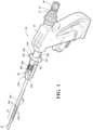
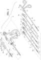
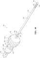
- a surgical instrument 10for use in a medical procedure for a patient (not shown). As illustrated in FIG. 2 , the surgical instrument 10 is used with one or more working tools 12. The surgical instrument 10 is capable of receiving and releaseably securing one of the working tools 12.
- Exemplary working tools 12may be a flexible bur 12a, a flexible bur 12b, a flexible high speed bur 12c, a flexible suction device 12d, a flexible internal imaging and suction device 12e, and/or a flexible manual instrument 12f such as graspers, bipolar forceps, etc.
- Powered tissue devices 12a, 12b, and 12c and manual instrument 12fcomprise a shaft portion 14 and a local flexible region 15 along the shaft portion 14 near a distal end.
- the flexible suction device 12d and flexible internal imaging and section device 12e of the working tools 12are devices that are configured to flex along at least a portion, of the entire length of the shaft portion 14.
- each of these working tools 12also have a generally cylindrical enlarged insertion portion 16 along the shaft portion 14 near a proximal end and a flange portion 17 extending radially outwardly at the end of the insertion portion 16.
- Each of these working tools 12a, 12b, 12cfurther comprise a connecting portion 18 extending axially away from the flange portion 17.
- the connecting portion 18is configured to couple the working tool 12 to a power source, a suction source, and/or irrigation source (not shown).
- each of these working tools 12d, 12e, 12fhave a connecting portion 18 for connection to a suction source only.
- the working tools 12 illustrated hereinare mere examples of the various working tools 12 that are configured to be inserted into the surgical instrument 10.
- other working tools 12may be introduced through and controlled by the surgical instrument 10 such as reciprocating devices like rasps, rotating devices, electrosurgical devices, laser devices, screwdriver devices, obturators, and trocars are further contemplated for use with the surgical instrument 10.
- the working tool 12is configured to be inserted into the surgical instrument 10 and extend outwardly from the surgical instrument 10.
- the surgical instrument 10may be operated by a user (not shown) such as a surgeon.
- the surgical instrument 10includes an articulating tube assembly, generally indicated at 20, and an actuation assembly, generally indicated at 22, coupled to the articulating tube assembly 20 and which controls the articulating tube assembly 20.
- the articulating tube assembly 20includes an articulating region 23 along a length of the articulating tube assembly 20.
- the articulating region 23is disposed proximal the distal end and may be axially spaced from the distal end of the articulating tube assembly 20 or may be axially abutting the distal end of the articulating tube assembly 20.
- one or more of the working tools 12have a shaft portion 14 capable of fitting within the articulating tube assembly 20 such that the flexible region 15 of the working tool 12 tends to align or at least partially align with the articulating region 23 when the working tool 12 is disposed in the surgical instrument 10.
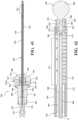
- the articulating tube assembly 20includes a first or inner tube 24 and a second or outer tube 26.
- Each of the inner tube 24 and outer tube 26are generally hollow cylinders and has a generally circular cross-sectional shape.
- the outer tube 26has a diameter greater than a diameter of the inner tube 24 such that the inner tube 24 is disposed within the outer tube 26.
- the inner tube 24 and outer tube 26extend axially between a proximal end and a distal end.
- the inner tube 24 and outer tube 26may have larger diameters such as approximately 10 mm or larger sufficient to accommodate the working tools 12 such as a screwdriver. It should still further be appreciated that, in certain embodiments, the diameter of the inner tube 24 and outer tube 26 may be scaled larger or smaller depending on the application and the size of the working tool 12.
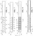
- the inner tube 24 and outer tube 26each include the articulating region 23 are fixed together distal of the articulating regions 23 to allow the inner tube 24 and outer tube 26 to be pushed and pulled relative to each other.
- the inner tube 24includes apertures 32, beams 34, tie straps 40, apertures 42, and bottom segments 44 to form the articulating region 23 in the inner tube 24.
- the outer tube 26includes apertures 60, beams 62, tie straps 68, apertures 70, and bottoming segments 72 to form the articulating region 23 in the outer tube 26.
- the inner tube 24includes an aperture 28 extending diametrically therethrough near the distal end thereof to allow the inner tube 24 to be fixed to the outer tube 26.
- the aperture 28is generally circular in shape, but may be any suitable shape.
- the inner tube 24includes an aperture 30 extending through a wall thereof and disposed between the articulating region 23 and the proximal end for a connection to be described. In one embodiment, the aperture 30 is generally elongated, but may be any suitable shape.
- the articulating region 23 of the inner tube 24includes one or more apertures 32 extending through a wall thereof.
- the apertures 32are generally rectangular in shape. However, other shapes of the apertures 32 are contemplated.
- the apertures 32have an axial length greater than a circumferential width, but need not be so.
- the inner tube 24includes a plurality of beams 34 formed by cutting the apertures 32 and 42.
- the beams 34extend axially to form generally linear beams 34. These beams 34 are parallel and extend from a long proximal portion 36 of the inner tube 24 to a shorter distal portion 38 of the inner tube 24.
- the beams 34are located approximately ninety degrees (90°) from each other as illustrated in FIG. 10 .
- the inner tube 24also includes one or more of tie straps 40 formed by cutting the apertures 32.
- the tie straps 40extend circumferentially between and spaced axially along the beams 34.
- each of the beams 34may be instead one continuous axially extending beam or a plurality or series of axially extending beams 34.
- the tie straps 40collectively maintain a cylindrical profile of the articulating region 23 of the inner tube 24 and prevent the beams 34 from buckling during compression of the inner tube 24.
- the beams 34are the main tension or compression members, deliver loads, and have to bend.
- the apertures 32are formed by cutting the inner tube 24.
- the inner tube 24includes one or more apertures 42 extending radially therethrough below the beams 34.
- the apertures 42have an inverted generally pentagonal shape.
- the apertures 42are formed by cutting the inner tube 24.
- the inner tube 24also includes one or more bottoming segments 44 formed by cutting the apertures 42 disposed below and extending from the beams 34.
- the bottoming segments 44are generally triangular or pentagonal in shape, but may be any suitable shape.
- the bottoming segments 44extend circumferentially between and spaced axially along the beams 34.
- Each of the bottoming segments 44have a lower side 46 that is inclined by a predetermined angle, for example such as approximately two and one half degrees (2.5°) in one embodiment.
- the bottoming segments 44have a bottom 48 that extends axially a distance greater than a top 50 thereof. It should be appreciated that the bottoming segments 44 bottom out and provide surface to surface contact against each other in an articulated or curved configuration. It should also be appreciated that an axial gap or space is formed between the bottoming segments 44. It should further be appreciated that the apertures 42, beams 34, and bottoming segments 44 allow the articulating region 23 of the inner tube 24 to articulate. It should further be appreciated that each of the bottoming segments 44 has, when articulated, a small angular displacement such as approximately three and one-half degrees (3.5°) or approximately four degrees (4°).
- the outer tube 26also includes an aperture 52 extending diametrically therethrough near the distal end thereof for a function to be described.
- the outer tube 26includes a slot aperture 54 extending through a wall thereof and disposed between the articulating region 23 and the proximal end for a function to be described.
- the slot aperture 54extends axially and is elongated.
- the outer tube 26includes a pad 56 disposed in the slot aperture 54 and a tab 58 extending axially between the outer tube 26 and the pad 56 to temporarily connect the pad 56 to the outer tube 26.
- the pad 56is generally elongated axially.
- the articulating region 23 of the outer tube 26includes one or more apertures 60 extending through a wall thereof.
- the apertures 60are generally rectangular in shape.
- the apertures 60are formed by cutting the outer tube 26.
- the outer tube 26also includes a plurality of beams 62 formed by cutting the apertures 60.
- the beams 62extend axially to form generally linear beams 62. These beams 62 are parallel to each other and extend from a long proximal portion 64 of the outer tube 26 to a shorter distal portion 66 of the outer tube 26 as illustrated in FIGS. 6 and 7 .
- the beams 62are located approximately ninety degrees (90°) circumferentially from each other. It should be appreciated that the beams 62 are the main tension or compression members, deliver loads, and have to bend.
- the outer tube 26includes a plurality of tie straps 68 formed by cutting the apertures 60 extending circumferentially between and axially spaced along the beams 62.
- the tie straps 68prevent the beams 62 from buckling during axial compression of the outer tube 26.
- the tie straps 68are generally "V" shaped axially toward the distal portion 66 to prevent snagging on the bottoming segments 44 of the inner tube 24 when the tube assembly 20 is articulated. It should be appreciated that each of the beams 62 may instead be one continuous axially extending beam or a plurality or series of axially extending beams 62.
- tie straps 68maintain a cylindrical profile of the articulating region 22 of the outer tube 26 and prevent the beams 62 from buckling during compression of the outer tube 26. It should also be appreciated that the tie straps 68 have a slight "V" form so to facilitate the passage of the segments 44 of the inner tube 24 past the tie straps 68 of the outer tube 26.
- the outer tube 26includes one or more apertures 70 extending radially therethrough below the beams 62.
- the apertures 70have an inverted generally pentagonal shape.
- the apertures 70are formed by cutting the outer tube 26.
- the outer tube 26includes one or more bottoming segments 72 formed by cutting the apertures 70 disposed below and extending from the beams 62.
- the bottoming segments 72are generally pentagonal in shape, but may be any suitable shape.
- the bottoming segments 72extend circumferentially between and are spaced axially along the beams 62.
- the bottoming segments 72have a bottom 74 that extends axially a distance greater than a top 76 thereof. It should be appreciated that the bottoming segments 72 provide rigidity in an axial extending or straight configuration. It should also be appreciated that a narrow axial gap or space is formed between the bottoming segments 72.
- Each bottom 74 of the bottoming segments 72has a first protrusion 78 extending axially from a proximal end toward the proximal end of the outer tube 26 and a first recess 80 extending axially from the proximal end toward the distal end of the outer tube 26.
- Each bottom 74 of the bottoming segments 72has a second protrusion 82 extending axially from a distal end toward the distal end of the outer tube 26 and a second recess 84 extending axially from the distal end toward the proximal end of the outer tube 26 in one embodiment.
- the inner tube 24has a greater number of apertures 42 forming the bottoming segments 44. In one embodiment, the inner tube 24 has fourteen apertures 42 and thirteen bottoming segments 44.
- the outer tube 26has a greater number of apertures 70 forming the bottoming segments 72. In one embodiment, the outer tube 26 has six apertures 70 and five bottoming segments 72. It should be appreciated that, in other embodiment, the number of apertures 42, 70 and segments 44, 72 may be greater or less.
- the distal portion 66 of the outer tube 26Adjacent the articulating region 23, the distal portion 66 of the outer tube 26 has a first projection 78 extending axially from a proximal end toward the proximal end of the outer tube 26 and a first recess 80 extending axially from the proximal end toward the distal end of the outer tube 26.
- the proximal portion 64 of the outer tube 26has a second protrusion 82 extending axially from a distal end toward the distal end of the outer tube 26 and a second recess 84 extending axially from a distal end toward the proximal end of the outer tube 26.
- the protrusions 78, 82 and recesses 80, 84are generally rectangular in shape.
- the first protrusion 78is disposed in the second recess 84 and the second protrusion 80 is disposed in the first recess 80 when the articulating section 23 is in an axially straight configuration.
- the protrusions 78, 82 and recesses 80, 84are formed by cutting the outer tube 26 in a narrow cut to form a general "zig zag" or "Z" shape pattern such that each segment 72 has protrusions 78, 82 that extend into the neighboring segments 72.
- the projections 78, 82 and recesses 80, 84facilitate the smooth passage of the tie straps 40 of the inner tube 24 past the edges of the bottoming segments 72 on the outer tube 26 and increase torsional and rotational stiffness of the outer tube 26. It should further be appreciated that the apertures 70, beams 62, and segments 72 allow the articulating region 23 of the outer tube 26 to articulate.
- the outer tube 26is pushed/pulled proximally with respect to the inner tube 24, causing the articulating tube assembly 20 to articulate until the bottoming segments 44 of the inner tube 24 bottom on each other and moves the outer tube 26 proximally with respect to the inner tube 24, causing the articulating tube assembly 20 to articulate until the bottoming segments 72 of the outer tube 26 bottom on each other.
- the proximal end of the outer tube 26is pulled distally relative to the inner tube 24, the beams 62 of the outer tube 26 are put in compression and the beams 34 of the inner tube 24 are put in tension.
- This loadingcauses a curve in the articulating region 23 of the articulating tube assembly 20 toward the beams 34 of the inner tube 24, which are in tension.
- the articulating region 23 of the articulating tube assembly 20curves until the bottoming segments 72 of the outer tube 26 bottom on each other, closing the small gap between these bottoming segments 72.
- the articulating region 23 of the articulating tube assembly 20is rigid as there is considerable loading about the circumference holding the bottoming segments 72 in place. Because there are relatively few and narrow gaps between bottoming segments 72 of the outer tube 26, it should be appreciated that relatively minimal tube curvature occurs. As this force is increased, the articulating tube assembly 20 becomes increasingly rigid in a nearly straight condition.
- the inner tube 24 and outer tube 26, when assembled,may lock in two directions such that the curves are in opposite directions or one curve in one direction is greater than the other curve in the other direction. It should also be appreciated that the outer tube 26 limits flexion for a straight configuration and the inner tube 24 limits flexion in a curved configuration.
- the pair of beams 34 of the inner tube 24 and the pair of beams 62 of the outer tube 26are oriented opposite at approximately one hundred eighty degrees (180°) from each other to provide lateral stiffness and rigidity of the articulating tube assembly 20.
- the pair of beams 34 of the inner tube 24 and the pair of beams 62 of the outer tube 26are oriented opposite at approximately one hundred seventy degrees (170°) to one hundred ninety degrees (190°) from each other. From these beams 34 and 62, the bottoming segments 44 and 72 and tie straps 40 and 68, respectively, are hung.
- the bottoming segments 44 and 72project toward and around a central axis or centerline A extending axially along the articulating tube assembly 20 and connect the two beams 34 and 62 together.
- the tie straps 40 and 68project away from, but around the centerline A and connect the two beams 34 and 62 together, respectively.
- the bottoming segments 44 and 72have distal and proximal surfaces and a small gap separating the distal surface of one bottoming segment 72 from the proximal surface of the next or adjacent bottoming segment 72.
- the bottoming segments 72 of the outer tube 26are considerably axially wider than the bottoming segments 44 of the inner tube 24 and the gap between the bottoming segments 72 of the outer tube 26 is considerably smaller than the gap between the bottoming segments 44 of the inner tube 24.
- each tube 24 and 26has two beams 34 and 62, respectively, at 90 degrees and each pair diametrically opposed from each other, other embodiments might have only one beam per tube. It should further be appreciated that, in still other embodiments, there may be more than two beams per tube. It should still further be appreciated that, at the proximal end of the surgical instrument 10, there are components that enable the surgeon to control the articulation and allow the surgical instrument 10 to attach to and be driven by a drive assembly (not shown).
- the articulating tube assembly 20includes a rotation assembly, generally indicated at 88, for angularly rotating a distal end of the articulating tube assembly 20.
- the rotation assembly 88includes an angular rotation tube 90 configured for rotating the inner tube 24 and outer tube 26.
- the angular rotation tube 90is a generally hollow cylinder having a generally circular cross-sectional shape.
- the angular rotation tube 90has a diameter greater than a diameter of the outer tube 26 such that the angular rotation tube 90 is disposed about the outer tube 26.
- the angular rotation tube 90extends axially a predetermined distance and has an axial length substantially less than an axial length of the outer tube 26.
- the angular rotation tube 90includes a slot aperture 92 extending through a wall thereof for a function to be described.
- the slot aperture 92is elongated axially.
- the angular rotation tube 90includes a pad 94 disposed in the slot aperture 92 and a tab 96 extending axially between the pad 94 and the angular rotation tube 90.
- the angular rotation tube 90is made of a metal material or non-metallic material depending on the application. It should be appreciated that the angular rotation tube 90 is fixed to the outer tube 26 and the outer tube 26 is fixed to the inner tube 24 in a manner to be described.
- the rotation assembly 88also includes an angular rotation collar 98 to be rotated by the user of the surgical instrument 10.
- the angular rotation collar 98may be generally circular in shape and include a pair of opposed protrusions 100 extending radially for a function to be described.
- the angular rotation collar 98also includes an aperture 102 extending axially therethrough to allow the angular rotation collar 98 to be disposed over and about the angular rotation tube 90.
- the angular rotation collar 98may include a knurled area 104 disposed in the aperture 102 for connection to the angular rotation tube 90.
- the angular rotation collar 98has an outer surface with a plurality of grooves 106 and a plurality of gripping members 108 extending axially and spaced circumferentially.
- the grooves 106 and gripping members 108are generally "V" shaped, but may be any suitable shape.
- One of the protrusions 100may include a recess 110 extending radially therein and axially therealong to allow the user to feel which way the articulating tube assembly 20 will articulate. It should be appreciated that the grooves 106 and 108 are formed on the protrusions 100.
- the angular rotation collar 98is coupled to the angular rotation tube 90 through a suitable mechanism such as the knurled area 104 to form a friction fit, adhesive bonding, or induction bonding.
- the articulating tube assembly 20also includes an inner thrust ring 112 attached to a proximal end of the inner tube 24.
- the inner thrust ring 112is generally cylindrical in shape with a generally circular cross-section.
- the inner thrust ring 112has an aperture 114 extending axially therethrough to be disposed about the inner tube 24.
- the aperture 114is generally circular in shape.
- the inner thrust ring 112also has a groove 116 extending radially therein and circumferentially thereabout for a function to be described.
- the groove 116has a generally "U" shaped cross-section. It should be appreciated that the inner thrust ring 112 is fixed to the inner tube 24 by a suitable mechanism such as knurling, adhesive bonding, or induction bonding.
- the articulating tube assembly 20also includes an outer thrust ring 118 attached to a proximal end of the outer tube 26.
- the outer thrust ring 118is generally cylindrical in shape with a generally circular cross-section.
- the outer thrust ring 118has an aperture 120 extending axially therethrough to be disposed about the outer tube 26.
- the aperture 120is generally circular in shape. It should be appreciated that the outer thrust ring 118 is fixed to the outer tube 26 by a suitable mechanism such as knurling, adhesive bonding, or induction bonding.
- the articulating tube assembly 20includes one or more spring washers 122 disposed about the outer tube 26 and adjacent each side of the outer thrust ring 118.
- Each spring washer 122is generally circular in shape with an aperture 124 extending axially therethrough to be disposed about the outer tube 26.
- the aperture 124is generally circular in shape.
- Each spring washer 122extends radially and axially. In the illustrated embodiment, each spring washer 122 is of a Bellville type.
- the articulating tube assembly 20also includes one or more flanged sleeves 126 disposed about the outer tube 26 and adjacent the washer 122 on each side of the outer thrust ring 118.
- Each flanged sleeve 126has a sleeve portion 128 with a generally hollow cylindrical in shape and a generally circular cross-section and a flange portion 130 extending radially from one end of the sleeve portion 128 and having a generally circular shape.
- Each flanged sleeve 126includes an aperture 132 extending axially through the sleeve portion 128 and flange portion 130.
- the aperture 132has a generally circular cross-section.
- the articulating tube assembly 20also includes one or more washers 134 disposed about the outer tube 26 and adjacent each of the flanged sleeves 126. Each washer 134 is generally circular in shape with an aperture 136 extending axially therethrough to be disposed about the outer tube 26.
- the aperture 136is generally circular in shape. Each washer 134 extends radially.
- the articulating tube assembly 20further includes one or more springs 138 disposed about the outer tube 26 and adjacent each washer 134. Each spring 138 is of a coil type having a plurality of helical shaped coils 140 extending circumferentially and axially.
- the assembly of the articulating tube assembly 20is illustrated.
- the inner tube 24is inserted into the outer tube 26 and oriented such that the beams 34 of the inner tube 24 are one hundred eighty degrees (180°) opposed to the beams 62 of the outer tube 26.
- the apertures 28 and 52act as an alignment hole through both tubes 24 and 26 such that a fixture pin (not shown) can align and position the tubes 24 and 26.
- a fixture pin(not shown) can align and position the tubes 24 and 26.
- a suitable mechanismsuch as an adhesive may used to secure the distal ends of the tubes 24 and 26 together. After the distal ends of the tubes 24 and 26 are fixed together, the fixture pin is removed.
- the pad 54 of the outer tube 26is also welded to the proximal end of the inner tube 24.
- the pad 94 of the angular rotation tube 90is then welded to the pad 54 of the outer tube 26.
- the tab 58 of the outer tube 26is then removed.
- the slot aperture 92 in the angular rotation tube 90 and the aperture 30 in the inner tube 24allow for this tab 58 to be cut and removed through a suitable mechanism such as a laser (not shown).
- a second personis not needed to hold the tubes 24, 26, and 90 to perform the assembly.
- a windowmay be provided to weld the tubes 24, 26, and 90 together.
- the pad 94acts as a leaf spring to allow the pad 54 to be drawn down against the inner tube 24. It should still further be appreciated that a torque applied to angular rotation collar 98 is transferred to the angular rotation tube 90 to which it is attached, and then to the pad 94 of the angular rotation tube 90 because it is constrained within its slot aperture 92. It should yet further be appreciated that, in this way, the tubes 24, 26, and 90 are all rotationally constrained to one another yet the proximal end of the outer tube 26 is free to move axially with respect to the other tubes 24 and 90.
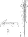
- the actuation assembly 22is coupled to the articulating tube assembly 20 for moving the inner tube 24 and the outer tube 26 axially relative to each other for articulating the articulating section 23 of the articulating tube assembly 20 between a straight configuration and a curved configuration in only one direction.
- the actuation assembly 22includes a handle 144 and one or more triggers 146, 148 coupled to the handle 144 to enable control of the articulating tube assembly 20.
- the handle 144includes a tube receiving portion 150 extending axially and a handle portion 152 extending radially downward from the tube receiving portion 150.
- the tube receiving portion 150is generally cylindrical shape.
- the tube receiving portion 150has a first or forward cavity 154 extending axially rearward therein.
- the forward cavity 154is generally cylindrical and circular in cross-sectional shape.
- the tube receiving portion 150includes one or more apertures 156 extending radially into the forward cavity 154.
- the apertures 156are generally circular in shape and spaced circumferentially.
- the tube receiving portion 150also has a second or rearward cavity 158 extending axially forward therein.
- the rearward cavity 158is generally cylindrical and circular in cross-sectional shape.
- the tube receiving portion 150includes one or more apertures 160 extending radially into the rearward cavity 158.
- the apertures 160are generally circular in shape and spaced circumferentially.
- the apertures 160are also semi-hemispherical shaped for a function to be described.
- the tube receiving portion 150has a central cavity 162 extending axially therein.
- the central cavity 162is generally cylindrical and circular in cross-sectional shape.
- the tube receiving portion 150includes one or more apertures 164 extending perpendicularly with respect to axis A into the central cavity 162.
- the apertures 164are generally circular in shape and spaced symmetrically off-axis.
- the tube receiving portion 150also has a passageway 166 extending axially between and communicating with the rearward cavity 158 and the central cavity 162.
- the passageway 166has a generally circular cross-section.
- the tube receiving portion 150includes an aperture 168 extending radially therethrough.
- the aperture 168has a generally circular cross-section.
- the tube receiving portion 150further includes an aperture 170 disposed above the central cavity 162 and extending perpendicularly therethrough for a function to be described. It should be appreciated that the passageway 166 is used to support the proximal end of the inner tube 24.
- the handle portion 152extends downwardly and away from the tube receiving portion 150 adjacent the central cavity 162.
- the handle portion 152is generally rectangular in shape.
- the handle portion 152includes an aperture 172 extending generally perpendicular therethrough.
- the aperture 172is generally elongated along the handle portion 152.
- the handle portion 152also includes a cavity 174 extending from the forward side toward the rearward side to receive the triggers 146, 148.
- the cavity 174is generally rectangular in shape.
- the cavity 174communicates with the aperture 172.
- the handle portion 152also includes an aperture 176 extending generally perpendicular therethrough and communicating with the cavity 174.
- the aperture 176is generally circular in shape.
- the triggers 146, 148include an upper or top trigger 146 and a lower or bottom trigger 148.
- the upper trigger 146has a trigger portion 182 extending forward and a flange portion 184 extending upwardly from the trigger portion 182.
- the trigger portion 182is generally rectangular in shape, but may be any suitable shape, and includes a trigger surface 186 being generally arcuate in shape to receive a finger of the user.
- the flange portion 184includes a pair of opposed flanges 190 extending from the trigger portion 182 and spaced laterally.
- the flanges 190include an aperture 192 extending therethrough.
- the aperture 192is generally circular in shape.
- the upper trigger 146includes a pin 194 extending through the apertures 192 in the flanges 190 and the aperture 170 in the tube receiving portion 150 to pivotally connect the upper trigger 146 to the handle 144.
- the upper trigger 146is made of a rigid material such as plastic.
- the upper trigger 146is integral, unitary, and one-piece. It should be appreciated that the upper trigger 146 moves the outer tube 26 proximally when actuated causing articulation.
- the lower trigger 148has a connecting portion 196 coupled to the handle portion 152 and a trigger portion 198 coupled to the connecting portion 196.
- the connecting portion 196includes a body portion 200 extends axially.
- the body portion 200is generally rectangular in shape with a lower surface 202 having a generally arcuate shape.
- the body portion 200includes a slot 204 extending radially therein and generally perpendicular thereto.
- the slot 204is generally rectangular in shape.
- the body portion 200has a first aperture 206 extending axially therethrough and a second aperture 208 extending generally perpendicular therethrough.
- the apertures 206 and 208are generally circular in shape.
- the connecting portion 196includes a flange portion 210 extending upwardly from the body portion 200.
- the flange portion 210includes a pair of opposed flanges 212 extending from the body portion 200 and spaced laterally. The flanges 212 are disposed in the slots 180.
- the lower trigger 148includes a pin 214 extending through the aperture 208 in the connecting portion 196 and the aperture 176 in the handle portion 152 to pivotally connect the lower trigger 198 to the handle 144.
- the pin 214is generally cylindrical in shape with a generally circular cross-section.
- the connecting portion 196is made of a rigid material such as plastic.
- the connecting portion 196is integral, unitary, and one-piece.
- the trigger portion 198has a body portion 216 extending vertically and a finger portion 218 extending forward from the body portion 216.
- the body portion 216has an upper surface 220 with a generally arcuate shape.
- the body portion 216includes a projection 222 extending upwardly to be disposed in the slot 204 of the connecting portion 196.
- the trigger portion 198includes a pin 224 extending through the aperture 206 in the connecting portion 196 and the aperture 176 in the handle portion 152 to pivotally connect the trigger portion 198 to the connecting portion 196.
- the pin 224is generally cylindrical in shape with a generally circular cross-section.
- the finger portion 218is generally rectangular in shape, but may be any suitable shape, and includes a trigger surface 226 being generally arcuate in shape to receive a finger of the user.
- the finger portion 218has a lower surface 227 being generally arcuate in shape.
- the finger portion 218may include a recess 228 extending perpendicularly therein.
- the finger portion 218may include one or more projections or teeth 230 extending generally perpendicular into the recess 228.
- the teeth 230are generally rectangular in shape, but may be any suitable shape.
- the teeth 230are spaced in a circumferential or arcuate manner adjacent the lower surface 227 of the finger portion 218 for a function to be described.
- the trigger portion 198is made of a rigid material such as plastic.
- the trigger portion 198is integral, unitary, and one-piece. It should be appreciated that the lower trigger 148 moves the inner tube 24 distally when actuated pushing the articulating tube assembly 20 to a straight configuration. It should also be appreciated that, another configuration, besides the handle 144 and triggers 146, 148 may be used to push or pull the inner tube 24 and outer tube 26 relative to each other to actuate and articulate the articulating tube assembly 20.
- the assembly of the actuation assembly 22is illustrated.
- the proximal end of the assembled articulating tube assembly 20is extended through the forward cavity 154 and into the central cavity such that the inner thrust ring 112 is disposed at the end of the central cavity 162 and the end of the inner tube 24 is disposed in the passageway 166.
- Pins through apertures 164 and groove 116secure the inner tube 24 axially, but allows rotation.
- a split sleeve bushing 232 disposed in the forward cavity 154extends axially and supports the tube assembly 20.
- the split sleeve bushing 232is generally a hollow cylinder having a generally circular cross-sectional shape to allow the articulating tube assembly 20 to extend therethrough.
- the split sleeve bushing 232may include a groove 234 to receive pins 236, which retain the bushing 232 and resist distal spring 138 in FIG. 11 .
- the pins 236are generally cylindrical in shape with a generally circular cross-section. The pins 236 extend through apertures 237 in the tube receiving portion 250 to secure the inner tube axially in the handle 144, but enables rotation.
- the upper trigger 146is disposed in the cavity 174 and the flanges 190 are extended around the articulating tube assembly 20 between the washer 134 and flanged sleeve 126 and upwardly into the slots 180 such that the apertures 192 and 170 align.
- the pin 194is then extended through the aperture 170 and apertures 192 to pivotally connect the upper trigger 146 to the actuation assembly 22.
- the articulating tube assembly 20extends axially through a space between the flanges 190 of the upper trigger 146.
- the pin 194allows pivotal movement of the upper trigger 146 forward and rearward and the flanges 190 and slots 180 guide the movement.
- the lower trigger 148is disposed in the cavity 174 and the flanges 212 are extended around the articulating tube assembly 20 between the flanged sleeve 126 and washer 134 and upwardly into the slots 180 such that the apertures 208 and 176 align.
- the pin 214is then extended through the apertures 208 and aperture 176 to pivotally connect the lower trigger 148 to the actuation assembly 22. It should be appreciated that the articulating tube assembly 20 extends axially through a space between the flanges 212 of the lower trigger 148.
- pin 214allows pivotal movement of the lower trigger 148 forward and rearward and the flanges 190 and slots 180 guide the movement. It should further be appreciated that the pin 224 allows pivotal movement of the trigger portion 198 of the upper trigger 146 perpendicularly from side to side.
- the working tool 12is inserted into the surgical instrument 10.
- the shaft portion 14is inserted into the rearward cavity of the actuation assembly 22 and extended axially through the inner tube 24.
- the insertion portion 16is also inserted into the rearward cavity 158 of the actuation assembly 22 and extended axially until the flange portion 17 abuts the rear of the actuation assembly 22.
- a spherically shaped ball 238ais disposed in one of the apertures 160 engages one of a plurality of detents 238b in the insertion portion 16 as illustrated in FIG. 5 .
- a collar 239may be disposed about the proximal end of the tube receiving portion 250.
- the collar 239is generally cylindrical with a generally circular cross-section and is pushed against the ball 238a by a spring 239c.
- the collar 239has an inner ramp 239a that engages the ball 238a to prevent rotation of the working tool 12 and lock the working tool 12 in place relative to the tube receiving portion 250 of the actuation assembly 22.
- a plurality of detents 238bmay be provided for multiple positions to vary amount of exposure of the distal end of the working tool 12 out of the distal end of the articulating tube assembly 20.
- the connecting portion 18 of the working tool 12may be connected to a power source (not shown).
- the lower trigger 148moves out, and the outer tube 26 is pushed proximally with respect to the inner tube 24, causing the tube assembly 20 to articulate as described below until the bottoming segments 44 of the inner tube 24 bottom on each other. While in this state, the lower trigger 148 can pivot to the side about the pin 224 and engage the bottom trigger teeth 230 into the slots 178 in the handle portion 152 of the handle 144, locking the instrument 10 in this condition. Pushing the lower trigger 148 to the opposite side disengages these teeth 230, unlocking the articulation control.
- Pushing the lower trigger 148 now into the handle 144causes the upper trigger 146 to move out and moves the outer tube 26 distally with respect to the inner tube 24, causing the tube assembly 20 to articulate as described below until the bottoming segments 72 of the outer tube 26 bottom on each other.
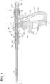
- the surgical instrument 10may be configured to include a tool view or viewing assembly, generally indicated at 240 in FIGS. 1 and 2 , which is an option provided for the user.
- the viewing assembly 240may include relatively small visualization and illumination elements at its distal tip that are able to present the user real time video from their perspective at the tip of the viewing assembly 240.
- the viewing assembly 240can be slipped over the articulating tube assembly 20 of the surgical instrument 10.
- Other configurationsare also contemplated such that the viewing assembly 240 may be disposed within the articulating tube assembly 20 or integral with one or more components of the articulating tube assembly 20.
- the viewing assembly 240includes a main tube 242 extending axially.
- the main tube 242is a generally hollow cylinder and has a generally circular cross-sectional shape.
- the main tube 242has a diameter greater than a diameter of the outer tube 26 such that the outer tube 26 is disposed within the main tube 242.
- the main tube 242extends axially between a proximal end and a distal end.
- the main tube 242has an axial length shorter than an axial length of the outer tube 26 such that the outer tube 26 extends past a distal end of the main tube 242 when the outer tube 26 is disposed within the main tube 242.
- the main tube 242is made of a metal material such as stainless steel or a non-metallic material such as a composite depending on the application. It should be appreciated that the wall thickness of the main tube 242 is relatively thin such as approximately 0.1 to approximately 0.5 millimeters (mm). It should also be appreciated that the diameter of the main tube 242 has a relatively small diameter so as to work in a small opening of the patient and to prevent the user's view from being obstructed.
- the main tube 242also includes a flexible region 23a along a length thereof.
- the flexible region 23ais disposed between the proximal end and distal end of the main tube 242.
- the flexible region 23amay have any suitable configuration to allow it to flex such as apertures 244 extending radially through and circumferentially across a wall of the main tube 242.
- the apertures 244are spaced axially along the flexible region 23a of the main tube 242. It should be appreciated that the apertures 244 may be cut in the main tube 242 by a laser or wire EDM (not shown).
- the main tube 242is capable of fitting over the articulating tube assembly 20 and the flexible region 23a of the main tube 242 tends to align when seated on the surgical instrument 10 with the articulation region 23 of the articulating tube assembly 20.
- the viewing assembly 240may include at least one imaging element 246 located at a distal end of the main tube 242.
- the imaging element 246is a camera, video camera, or of a camera chip, with wires (not shown) to the camera.
- the imaging element 246is connected to the distal end of the main tube 242 by a suitable mechanism such as an adhesive or epoxy.
- the viewing assembly 240may include an illumination assembly, generally indicated at 248, for illuminating the surgical site at a distal end of the articulating tube assembly 20.
- the illumination assembly 248includes one or more illuminators 250 such as light emitting diodes (LEDs) located at the distal end of the main tube 242.
- LEDslight emitting diodes
- one illuminator 250is located on one side of the imaging element 246 and another illuminator 250 is located on the other side of the imaging element 246.
- the illuminators 250are connected to the distal end of the main tube 242 by a suitable mechanism such as an adhesive or epoxy.
- the illuminators 250are also connected by wires 252 to a power source (not shown). It should be appreciated that the illuminators 250 may be configured as plastic optical fibers coupled to a remote light source (not shown).
- the viewing assembly 240may include a shroud 254 attached to the main tube 242 to cover the imaging element 246, illuminators 250, and wires 252.
- the shroud 254extends axially along the main tube 242 from the distal end toward the proximal end and over the articulating region 23.
- the shroud 254has a generally arcuate configuration to form a passageway for the wires 252 and camera wires (not shown).
- the shroud 254may be connected to the main tube 242 by a suitable means such as welding.
- the shroud 254is made of a metal material such as stainless steel or a non-metallic material such as a composite depending on the application.
- the shroud 254also includes a flexible region 23a along a length thereof.
- the flexible region 23ais disposed between the proximal end and distal end of the shroud 254.
- the flexible region 23amay have any suitable configuration to allow it to flex such as apertures 256 extending radially through and circumferentially across a wall of the shroud 254.
- the apertures 256are spaced axially along the flexible region 23a of the shroud 254. It should be appreciated that the apertures 256 may be cut in the shroud 254 by a laser or wire EDM (not shown). It should also be appreciated that the main tube 242 and shroud 254 flex left to right, but not up and down to prevent the wires 252 from being compressed and extended.
- the viewing assembly 240also includes a connector 258 having a distal end connected to a proximal end of the main tube 242.
- the connector 258extends axially and has a slot 260 extending radially therethrough to form a generally "U" shape.
- the connector 258has a diameter larger than a diameter of the tube receiving portion 150 of the actuation assembly 22. It should be appreciated that the collar 98 is disposed in the slot 260 and the amount of rotation is limited by the protrusions 100 on the collar 98 to prevent flexing at the six o'clock and twelve o'clock positions, but allowing flexing at the three o'clock and nine o'clock positions.
- the viewing assembly 240allows real time video to be presented to the user on a video monitor (not shown) for a primary view, and in another embodiment, as a small picture-in-picture in the corner of the screen of the video monitor for a secondary view for an endoscope (not shown), or in the corner of their microscope image.
- a video monitornot shown
- an endoscopenot shown
- the usermaintains the "global view” they currently have with their current visualization tools, while being provided a perspective deep within the surgical site very near the tip of the working tool 12.
- the viewing assembly 240may be advanced or retracted along the length of the articulating tube assembly 20 such that in the fully retracted position, the distal tip of the viewing assembly 240 is proximal of the articulating region 23 of the articulating tube assembly 20, and in more advance positions the distal tip of the viewing assembly 240 is just distal of the articulating region 23 or, in even more advanced positions, the distal tip of the viewing assembly 240 is distal of the tip of the working tool 12.
- the surgical instrumentprovides a primary view in one embodiment and a secondary local view in another embodiment for a surgeon.
- the surgical instrumentincludes imaging elements at a distal tip to provide the secondary local view for the surgeon.
- the surgical instrumentincludes an imaging element capable of being moved along an axis of the instrument.
- the surgical instrumentincludes an illumination device to provide illumination at the surgical site.
- the surgical instrument 110includes the articulating tube assembly 120 and a new actuation assembly 122 coupled to the articulating tube assembly 120 for moving the inner tube 124 and the outer tube 126 axially relative to each other for articulating the articulating section 123 of the articulating tube assembly 120 between a straight configuration and a curved configuration in only one direction. It should also be appreciated that, at the proximal end of the surgical instrument 110, there are components that enable the surgeon to control the articulation and allow the surgical instrument 110 to attach to and be driven by a drive assembly (not shown).
- the actuation assembly 122includes a handle 244 including a tube receiving portion 250 extending axially.
- the tube receiving portion 250is generally cylindrical shape.
- the tube receiving portion 250has a first or forward cavity 254 extending axially rearward therein.
- the forward cavity 254is generally cylindrical and circular in cross-sectional shape.
- the tube receiving portion 250also has a second or rearward cavity 258 extending axially forward therein.
- the rearward cavity 258is generally cylindrical and circular in cross-sectional shape.
- the rearward cavity 258communicates axially with the forward cavity 254.
- the tube receiving portion 250includes one or more apertures 260 extending perpendicularly into the rearward cavity 258.
- the apertures 260are generally circular in shape and spaced symmetrically about the axis.
- the tube receiving portion 250has a central cavity 262 extending radially and axially therein.
- the central cavity 262is generally rectangular in shape.
- the tube receiving portion 250includes one or more apertures 264 extending radially into the central cavity 262.
- the apertures 264are generally circular in shape and spaced circumferentially.
- the tube receiving portion 250further includes an aperture 265 disposed below the central cavity 262 and extending radially therethrough for a function to be described.
- the tube receiving portion 250may include a pair of slots 280 extending axially therein and communicating with the central cavity 262.
- One of the slots 280is spaced radially from one side of the forward cavity 254 and another slot 280 is spaced radially from an opposed side of the forward cavity 254.
- the tube receiving portion 250is made of a rigid material such as plastic.
- the tube receiving portion 250is integral, unitary, and one-piece. It should be appreciated that the forward cavity 254 is used to support the proximal end of the inner
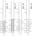
- the actuation assembly 122also includes a collar 368 connected to a proximal end of the outer tube 126.
- the collar 368is generally rectangular in shape.
- the collar 368includes an aperture 370 extending axially therethrough.
- the aperture 370is generally circular in shape.
- the collar 368also includes a plurality of apertures 372 extending axially therethrough.
- the apertures 372are generally rectangular in shape.
- One of the apertures 372is spaced radially from one side of the aperture 370 and another aperture 372 is spaced radially from an opposed side of the aperture 370.
- the collar 368further includes one or more apertures 374 extending radially therethrough and communicating with the apertures 372.
- the apertures 374are generally circular in shape.
- One of the apertures 374is located on one side of the collar 368 and communicating with the aperture 372 and another aperture 374 is located on another side of the collar 368 and communicating with the aperture 372. It should be appreciated that the aperture 370 has a diameter to receive the outer tube 126 to form a friction fit, adhesive bond, or induction bond therebetween.
- the actuation assembly 122includes one or more links 376 connected to the collar 368.
- the links 376extend axially.
- the links 376are generally rectangular in shape.
- the links 376have an aperture 378 extending through each end thereof.
- the distal end of the links 376is disposed in the apertures 372 of the collar 368 until the apertures 378 and 374 are aligned.
- the actuation assembly 122includes one or more pins 380 to connect the distal end of the links 376 to the collar 368.
- the pins 380are generally cylindrical in shape with a generally circular cross-section.
- the pins 380are disposed in the apertures 374 and 378 to connect the links 376 to the collar 368. It should be appreciated that the proximal end of the links 376 are disposed in the slots 280 of the tube receiving portion 250.
- the actuation assembly 122also includes a lever 380 connected to the proximal end of the links 376.
- the lever 380has a generally inverted "U" shape.
- the lever 380has a top portion 382 and a pair of side portions 384 being spaced and extending from the top portion 382.
- the side portions 384include an upper aperture 386 and a lower aperture 388 extending therethrough.
- the upper aperture 386is spaced from the lower aperture 388.
- the side portions 384are disposed in the central cavity 262 until the apertures 388 and 265 are aligned and the apertures 386 and 264 are aligned.
- the actuation assembly 122includes one or more pins 390 and 392 to connect the side portions 384 of the lever 380 to the proximal end of the links 376.
- the pins 390 and 392are generally cylindrical in shape with a generally circular cross-section.
- the pin 390has a length greater than a length of the pins 392.
- the pins 390are disposed in the apertures 388 and 265 to connect the lever 380 to the tube receiving portion 250 of the handle 244 and the pins 392 pass through the apertures 264 and are disposed in the apertures 386 and 378 to connect the lever 380 to the links 376.
- the surgical instrument 110is illustrated with one of the surgical tools 12.
- the surgical instrument 110is capable of receiving the working tool 12 and releaseably securing the working tool 12 by a friction fit.
- the working tool 12is a flexible shaver 12g for use on the patient.
- the flexible shaver 12gmay include a housing hub 394 disposed in a proximal end of the handle 244 of the actuation assembly 122.
- the housing hub 394is generally cylindrical in shape with a generally circular cross-section.
- the housing hub 394extends axially from a proximal end to a distal end.
- the housing hub 394has a reduced diameter plug portion 395 at the distal end.
- the plug portion 395includes a groove 396 to receive pins 397 that extend through the handle 244 to lock the housing hub 394 to the handle 244.
- the housing hub 394also includes a cavity 398 extending axially into the proximal end thereof.
- the cavity 398is generally cylindrical in shape with a generally circular cross-section.
- the housing hub 394is integral, unitary, and one-piece.
- the flexible shaver 12galso has a shaft portion 14 and a local flex region 15 along the shaft portion 14 near a distal end.
- the shaft portion 14includes an inner tube 14a and an outer tube 14b.
- the outer tube 14bis fixedly connected to the housing hub 394.
- the flexible shaver 12galso have a generally cylindrical enlarged insertion portion 16 along the shaft portion 14 near a proximal end and a connecting portion 18 extending axially away from the proximal end of the insertion portion 16 for connection to a power source and suction (not shown).
- the inner tube 14aextends through the insertion portion 16 and is connected to the connecting portion 18. It should be appreciated that the connecting portion 18 is a cutter driveshaft that oscillates by rotating two to five turns and then changes direction.
- the outer tube 14bhas an opening 14c at the distal end thereof.
- the inner tube 14ahas a plurality of teeth 14d at its distal end to form a cutter that rotates relative to the outer tube 14b. It should be appreciated that the opening 14c in the outer tube 14b forms a window where tissue is pulled in and cut by the teeth 14d of the inner cutter.
- the inner tube 14ahas a bur 14e at its distal end to form a spinning bur. It should be appreciated that the opening 14c in the outer tube 14b allows the cutting by the spinning bur 14e of the inner tube 14a.
- the surgical instrument 10, 110allows the opening 14c of the outer tube 14b of the working tool 12g to be rotated with respect to the articulating tube assembly 20, 120. It should be appreciated that the flexible region 15 of the working tool 12g allows it to be rotated when the articulating region 23, 123 is bent or curved in only one direction.
- the surgical instrument 10, 110has tube articulation to facilitate reduced incision size, improved access and visibility, while enhancing surgical outcome and quicker recovery.
- the surgical instrument 10, 110includes a relatively simple, inexpensive, articulating tube assembly 20, 120 constructed of two laser cut tubes which are welded or bonded together at the distal end.
- the surgical instrument 10, 110includes a relatively inexpensive articulating tube assembly 20, 120 that is capable of locking very rigidly in both straight and curved positions.
- the surgical instrument 10, 110includes tube articulation that provides rigidity in these positions sufficient to resist off axis loading such as that seen with power-tool cutting.
- the surgical instrument 10,110includes tube articulation that allows for a large central opening to facilitate tissue extraction. Yet a further advantage of the present invention is that the surgical instrument 10, 110 includes an articulating tube assembly 20,120 that may provide a large central cannula that enables a variety of flexible devices to be inserted and so enables the articulating tube assembly 20, 120 to control their movement. Still a further advantage of the present invention is that the surgical instrument 10, 110 includes an articulating tube assembly 20, 120 capable of becoming rigid to resist off-axis loading. Yet still a further advantage of the present invention is that the surgical instrument 10, 110 includes an articulating tube assembly 20, 120 that has the ability to latch or bottom out in a straight position without snaking, and in a curved position, without snaking.
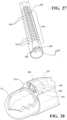
- the surgical instrument 210includes the articulating tube assembly 220 having a proximal end and a distal end.
- the articulating tube assembly 220includes the articulating region 223 disposed between the proximal end and the distal end and a proximal axis "P" axially extending from the proximal end to the articulating region 223.
- the articulating tube assembly 220includes the inner tube 224 and the outer tube 226 each having the articulating region 223.
- the inner tube 224 and the outer tube 226are movable relative to each other proximal to the articulating region 223 and fixed axially relative one another distal to the articulating region 223. It should be appreciated that the articulating tube assembly 220 is similar to the articulating tube assembly 20. It should also be appreciated that, in this embodiment of the surgical instrument 210, the articulating tube assembly 220 is a single integrated instrument that is devoid of a working channel for receiving the surgical tool 12.
- the articulating region 223is rigid in a first configuration and a second configuration relative to the proximal axis P to resist off-axial loading.
- the first configurationmay be a straight configuration relative to the proximal axis P and the second configuration may be a curved configuration relative to the proximal axis P.
- the first configurationmay be a curved configuration and the second configuration may be a curved configuration having a curvature greater than a curvature of the first configuration.
- FIG. 50illustrates one example of a curved configuration. The curved configuration extends only in a single plane up to one hundred eighty degrees relative to the proximal axis P.
- the curved configurationextends in only a single plane up to one hundred twenty degrees relative to the proximal axis P. In yet another embodiment, the curved configuration extends in only a single plane up to ninety degrees relative to the proximal axis P.
- the inner tube 224 and outer tube 226form an outer lumen and the mechanical mechanism for articulation.
- the inner tube 224 and outer tube 226are sized so that the tubes 224, 226 slide over one another with a close fit.
- the outer tube (226)has an outer diameter of approximately two millimeters (2 mm) to approximately twelve millimeters (12 mm).
- lasercutsare made in each tube 224, 226 and the tubes 224 and 226 are welded together at the distal end in a position so that the lasercut sections overlap.
- the sections cut away from the tubes 224 and 226allow them to bend in one direction, but not the other.
- the inner tube 224extends axially past a distal end of the outer tube 226.
- the tubes 224, 226do not have mechanical backlash and thus are rigid. It should also be appreciated that, at the proximal end of the surgical instrument 210, there are components that enable the surgeon to control the articulation and allow the surgical instrument 210 to attach to and be driven by a drive assembly (not shown). It should be further appreciated that a lasercut pattern for the inner tube 224 extends beyond the proximal and distal limits of the lasercut pattern for the outer tube 226 to prevent the articulating tube assembly 220 from possible fatiguing.
- the inner tube 224is fixed to a hub 400 to be described.
- the outer tube 226includes a slot aperture 254 extending through a wall thereof and disposed between the articulating region 223 and the proximal end.
- the slot aperture 254extends axially and is elongated.
- the outer tube 226includes a pad 256 disposed in the slot aperture 254 and a tab 258 extending axially between the outer tube 226 and the pad 256 to temporarily connect the pad 256 to the outer tube 226.
- the pad 256is generally elongated axially. After the distal ends of the tubes 224 and 226 are fixed, the pad 256 of the outer tube 226 is welded to the inner tube 224. The tab 258 of the outer tube 226 is then removed. It should be appreciated that the pad 256 acts as an anti-rotation mechanism between the inner tube 224 and the outer tube 226.
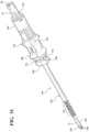
- the surgical instrument 210also includes an actuation assembly 222a coupled to the articulating tube assembly 220 for moving the inner tube 224 and the outer tube 226 axially relative to each other for articulating the articulating region 223 of the articulating tube assembly 220 between a straight configuration and one or more curved configurations in only a single plane.
- the actuation assembly 222aincludes a rotation assembly 288 disposed about the outer tube 226 to be rotated by a user.
- the rotation assembly 288includes a tube receiving portion or hub 400 connected to the inner tube 224.
- the hub 400is generally cylindrical and circular in shape, but may be any suitable shape.
- the hub 400includes a cavity 402 extending axially inward from a proximal end thereof and an aperture 404 extending axially inward from a distal end thereof to receive the inner tube 224.
- the inner tube 224is connected to the hub 400 by a suitable mechanism such as a friction fit, an adhesive, knurling, or thermally staking or thermally bonding to plastic.
- the hub 400includes a groove 406 extending axially inward from the distal end of thereof.
- the groove 406is generally circular in shape, but may be any suitable shape.
- the hub 400includes a flange 408 extending radially from the distal end thereof and having an external groove 410 extending radially inward.
- the hub 400may include one or more projections 412 extending axially and radially for coupling to a drive assembly (not shown).
- the hub 400is made of a plastic material.
- the hub 400is integral, unitary, and one-piece.
- the rotation assembly 288also includes a rotatable articulation control wheel 416 coupled to the outer tube 226 and being continuously adjustable to adjust a degree of curvature of the articulating region 223 of the articulating tube assembly 220 relative to the proximal axis P.
- the articulation control wheel 416is generally cylindrical and circular in shape, but may be any suitable shape.
- the articulation control wheel 416includes a cavity 418 extending axially inward from a proximal end thereof and an aperture 420 extending axially inward from a distal end thereof into which the outer tube 226 extends.
- the cavity 418includes one or more internal threads 422 extending axially and radially therealong.
- the articulation control wheel 416includes a flange 424 extending axially from a proximal end thereof to form a recess 426 for receiving a portion of the hub 400.
- the flange 424includes a radial projection 428 disposed in the external groove 410 to attach the articulation control wheel 416 to the hub 400 by a radial snap fit.
- the articulation control wheel 416may include a plurality of external projections 430 extending radially and axially and spaced circumferentially thereabout to be gripped by a hand of the user.
- the articulation control wheel 416is made of a plastic material.
- the articulation control wheel 416is integral.
- the articulation control wheel 416is rotatable by the hand of the user of the surgical instrument 210. It should also be appreciated that the only mechanical connection between the articulation control wheel 416 and the outer tube 226 is via the threads 422 of the articulation control wheel 416 interacting with threads of a leadscrew 432 to be described that is bonded to the outer tube 226.
- the rotation assembly 288includes a gear mechanism or lead screw 432 connected to the outer tube 226 and disposed in the cavity 418 of the articulation control wheel 416.
- the lead screw 432is generally cylindrical and circular in shape.
- the lead screw 432has an aperture 434 extending axially therethrough to receive the outer tube 226.
- the lead screw 432is bonded to the proximal end of the outer tube 226.
- the lead screw 432has one or more external threads 436 extending radially and axially therealong to matingly engage the internal threads 422 in the cavity 418 of the articulation control wheel 416.
- the internal threads 422 of the cavity 418 and the external threads 436 of the lead screw 432contain a matching thread pattern that drives the lead screw 432.
- the external threads 436have a pitch of approximately 0.2 inches to approximately 0.6 inches to prevent unintentional translation of the lead screw 432 under load. It should be appreciated that the pitch used on the lead screw 432 ensures that the articulation control wheel 416 does not rotate under load and is dependent on the material and the size of the threads.
- the rotation assembly 288may further includes a wave spring 438 disposed between the hub 400 and the articulation control wheel 416 to keep the hub 400 under load between the straight and curved configurations.
- the wave spring 438is generally circular in shape.
- the wave spring 438is made of a spring material.
- the wave spring 438may be disposed in the groove 406 of the hub 400. It should be appreciated that, by turning the articulation control wheel 416 clockwise and anti-clockwise, the outer tube 226 of the articulating tube assembly 220 is pushed/pulled proximal/distal, causing articulation of the articulating section 223.
- the articulation assembly 222amay include a locking assembly, generally indicated at 440, cooperating with the rotation assembly 288 to lock the rotation assembly 288 in one or more positions such that the articulating region 223 is locked in one or more curvature configurations and prohibits the articulation control wheel 416 from turning.
- the locking assembly 440includes a projection 442 extending axially from a distal end of the articulation control wheel 416 and having a cavity 444 extending axially inward.
- the cavity 444has a generally frustoconical or tapered shape.
- the projection 442includes one or more external threads 446 extending axially and radially and disposed circumferentially thereabout.
- the projection 442is integral, unitary, and one-piece with the articulation control wheel 416. It should be appreciated that the cavity 444 communicates with the aperture 420 of the articulation control wheel 416.
- the locking assembly 449also includes a floating collet 448 partially disposed in the cavity 444 of the projection 442 on the articulation control wheel 416.
- the floating collet 448is generally cylindrical and circular in shape, but may have any suitable shape.
- the floating collet 448has a central aperture 450 extending axially therethrough to receive the articulating tube assembly 220.
- the floating collet 448has a plurality of slits or slots 450 extending axially therealong and disposed circumferentially thereabout and spaced from the central aperture 450 to allow the central aperture 450 to be compressed about the outer tube 226 of the articulating tube assembly 220.
- the floating collet 448includes a first frustoconical portion 454 at a proximal end thereof and a second frustoconical portion 456 at a distal end thereof.
- the cavity 444 of the projection 442 of the articulation control wheel 416 and the proximal end of the floating collet 448have a tapered surface or shape to matingly engage each other.
- the floating collet 448is made of a plastic material or a metal material.
- the floating collet 448is integral, unitary, and one-piece.
- the locking assembly 440engages with the outer tube 226 of the articulating tube assembly 220 and prevents the articulating tube assembly 220 from being actuated by the articulation control wheel 416 and lead screw 432. It should also be appreciated that the locking assembly 440 may be engaged when the user has achieved their desired level of articulation and desires to lock the curvature of the articulating region 223 of the articulating tube assembly 220 in place. It should further be appreciated that the locking assembly 440 may only be necessary when the user is applying high levels of force.
- the locking assembly 440further includes a rotatable locking wheel 458 cooperating with the floating collet 448 and the projection 442 on the articulation control wheel 416.
- the locking wheel 458is generally cylindrical and circular in shape, but may have any suitable shape.
- the locking wheel 458has a cavity 460 extending axially inward from a proximal end thereof and a plurality of internal threads 462 disposed in the cavity 460 and extending radially and axially therealong to mate with the external threads 446 on the projection 442 of the articulation control wheel 416.
- the locking wheel 458also has a frustoconical recess 464 extending axially inward from the cavity 460 to receive the second frustoconical portion 456 of the floating collet 448.
- the frustoconical recess 464 of the locking wheel 458 and the second frustoconical portion 456 of the floating collet 448have a tapered surface or shape to matingly engage each other to cause a friction lock on the outer tube 226 to prevent the outer tube 226 from moving axially.
- the locking wheel 458may include a plurality of external projections 466 extending radially and axially and spaced circumferentially thereabout to be gripped by a hand of the user.
- the locking wheel 458is made of a plastic material.
- the locking wheel 458is integral, unitary, and one-piece. It should be appreciated that the floating collet 448 is shaped so that its internal diameter reduces as the locking wheel 458 is screwed down onto the projection 442 of the articulation control wheel 416. It should also be appreciated that this causes a friction lock on the outer tube 226 of the articulating tube assembly 220, thereby preventing the outer tube 226 from moving axially and causing unwanted bending or straightening of the articulating region 223 of the articulating tube assembly 220. It should further be appreciated that the locking assembly 440 is optional. It should still be further appreciated that other articulating mechanisms may be used to provide a similar function of preventing the outer tube 226 from moving axially and causing unwanted bending or straightening of the articulating region 223 of the articulating tube assembly 220.
- the surgical instrument 210includes a torque member 470 disposed within the inner tube 224 and extending axially.
- the torque member 470is generally cylindrical and circular in shape, but may be any suitable shape.
- the torque member 470may be a hollow tube or a solid member.
- the torque member 470may have a hollow distal end 472.
- the torque member 470may have a variable stiffness with a first stiffness in the articulating region 223 and a second stiffness greater than the first stiffness outside the articulating region 223.
- the torque member 470is made of a metal material.
- the torque member 470may be formed from wrapping wires helically into a tube shape known as a torque coil.
- the torque member 470is integral.
- the rigidity of the torque member 470 in the straight section of the articulating tube assembly 220reduces vibration during operation of a rotatable end effector 496 to be described. It should also be appreciated that the torque member 470 can transmit torque around the bent or curved articulating region 223 of the articulating tube assembly 220.
- the surgical instrument 210also includes a driveshaft 474 coupled to the torque member 470.
- the driveshaft 474is generally cylindrical and circular in shape, but may have any suitable shape.
- the driveshaft 474includes a cavity 476 extending axially inward from a distal end thereof for receiving a proximal end of the torque member 470.
- the torque member 470is mechanically bonded to the driveshaft 474 by a suitable mechanism such as a friction fit, adhesive, or keyway system (proximal end of the torque member 470 is machined to have a specific shape and is received with a matching shape in the driveshaft 474).
- the driveshaft 474also includes a plurality of external cutaways 478 spaced from the cavity 476 and extending axially partially therealong that are adapted to be coupled to a drive assembly (not shown).
- the driveshaft 474may be made of a plastic material or a metal material.
- the driveshaft 474is integral, unitary, and one-piece. It should be appreciated that torque member 470 passes through the hub 400 and the proximal end is disposed in the cavity 402 and bonded to the driveshaft 474, which interfaces with a drive mechanism of the drive assembly.
- the surgical instrument 210may include a suction path 480 formed between the inner tube 224 and the torque member 470.
- the suction path 480extends axially and circumferentially between the inner tube 224 and the torque member 470.
- the suction path 480includes at least one or more suction ports 482 extending through the inner tube 224 and the outer tube 226 and disposed axially between the articulating region 223 and a proximal end of a distal bearing to be described to allow removal of cutting debris and fluid therethrough and into the suction path 480.
- the suction ports 482are spaced circumferentially about the distal end of the outer tube 226.
- the distal end of the suction path 480fluidly communicates with the suction ports 482.
- the proximal end of the suction path 480fluidly communicates with the cavity 402 of the hub 400. It should be appreciated that the suction ports 482 may be formed by lasercuts into the distal end of the articulating tube assembly 220 to allow removal of cutting debris and fluid from a joint undergoing arthroscopy.
- the surgical instrument 210also includes a proximal bearing 484 disposed in the suction path 480 proximal the articulating region 223 to support the torque member 470.
- the proximal bearing 484is generally cylindrical and circular in shape, but may be any suitable shape.
- the proximal bearing 484has a central aperture 486 extending axially therethrough to allow the torque member 470 to extend through the proximal bearing 484.
- the proximal bearing 484includes a plurality of external cutaways 488 spaced from the central aperture 486 and extending axially therealong to allow fluid flow along the suction path 480 between the distal end and the proximal end of the suction path 480.
- the proximal bearing 484may be made of a plastic, ceramic, metal, or other suitable bearing material.
- the proximal bearing 484may be integral, unitary, and one-piece.
- the proximal bearing 484is fixed just proximal to the articulating region 223 of the articulating tube assembly 220. It should also be appreciated that the suction path 480 is in the lumen formed between the articulating tube assembly 220 and the torque member 470 and, for this reason, specific geometries are necessary on the proximal bearing 484 and the driveshaft 474 to allow unobstructed fluid flow therethrough to the drive assembly.
- the surgical instrument 210includes a distal bearing 490 disposed in the distal end of the inner tube 224 distal of the articulating section 223 to support an end effector to be described.
- the distal bearing 490is generally cylindrical and circular in shape, but may have any suitable shape.
- the distal bearing 490has a central aperture 492 extending axially therethrough.
- the distal bearing 490has a flange 494 extending radially from a distal end thereof to abut the distal end of the inner tube 224.
- the distal bearing 490has a clam shell configuration.
- the distal bearing 490may be made of a ceramic, metal, or other suitable bearing material.
- the distal bearing 490may be integral.
- the surgical instrumentfurther includes an end effector disposed distal of the articulation section 223 and coupled to the torque member 470.
- the end effectoris a rotatable end effector, generally indicated at 496, such as a bur.
- the rotatable end effector 496includes a head 498 at a distal end thereof and a shaft 500 extending from the head 498 to a proximal end coupled to the torque member 470.
- the head 498is generally spherical in shape, but may be any suitable shape.
- the head 498may be fluted or coated with a diamond grit to enable cutting of bone.
- the shaft 500is generally cylindrical and circular in shape, but may be any suitable shape.
- the shaft 500extends through the central aperture 492 of the distal bearing 490.
- the rotatable end effector 496includes a flange 502 extending radially from the shaft 500 and disposed axially between the head 498 and the proximal end of the shaft 500.
- the rotatable end effector 496includes a groove 504 extending radially and axially between the flange 502 and the head 498.
- the distal bearing 490is disposed in the groove 504 to prevent the rotatable end effector 496 from exiting the distal bearing 490.
- the rotatable end effector 496includes a barb 506 at the proximal end of the shaft 500 to be disposed in the hollow distal end 472 of the torque member 470 and the flange 502 abuts the end of the torque member 470.
- the barb 506is secured to the torque member 470 by a suitable mechanism such as welding. It should be appreciated that the head 498 is machined with the groove 504, allowing the rotatable end effector 496 to be held by the clamshell distal bearing 490 that fits into the distal end of the inner tube 224 of the articulating tube assembly 220.
- the rotatable end effector 496has the barb 506 machined at the proximal end, allowing the hollow distal end 472 of the torque member 470 to be welded onto the rotatable end effector 496. It should be further appreciated that other end effectors are contemplated other than rotatable end effectors such as any rotatable cutting element or tool.
- FIG. 51a method of operating a surgical instrument (10, 110, 210) is disclosed in FIG. 51 .
- the methodincludes the steps of providing an articulating tube assembly (20, 120, 220) having a proximal end and a distal end, an articulating region (23, 123, 223) disposed between the proximal end and the distal end, and a proximal axis P axially extending from the proximal end to the articulating region (23, 123, 223), the articulating tube assembly (20, 120, 220) including an inner tube (24, 124, 224) and an outer tube (26, 126, 226) each having the articulating region (23, 123, 223), the inner tube (24, 124, 224) and the outer tube (26, 126, 226) being movable relative to each other proximal to the articulating region (23, 123, 223) and fixed axially relative one another distal to the articulating region (23, 123, 22
- the methodis used typically for joint arthroscopy to examine and reshape/perform surgery on the inside structure of the joint.
- the methodis commonly used on knee joints.
- the procedureis performed by inserting the distal end of the articulating tube assembly (20, 120, 220) into the joint through a small incision in a patient. During this procedure, a separate tool is provided for irrigation of the joint.
- the inside of the jointis visualized using a separate arthroscopic camera.
- the methodincludes the steps of rotating the rotation assembly (288) of the actuation assembly (222a) with one hand of the user in block 604 and moving the inner tube (24, 124, 224) and the outer tube (26, 126, 226) axially relative to each other in block 606.
- the methodincludes the step of articulating the articulating region (23, 123, 223) of the articulating tube assembly (20, 120, 220) between a first configuration and a second configuration in only a single plane in block 608.
- the methodincludes the steps of rotating the rotation assembly (288) of the actuation assembly (222a) by a user to move the inner tube (224) and the outer tube (226) axially relative to each other.
- the methodincludes the steps of locking a locking assembly 440 cooperating with the rotation assembly (288) to lock the rotation assembly (288) in one or more positions such that the articulating region (223) is locked in one or more curvature configurations and does not straighten under load.
- the methodincludes the steps of providing a working tool 12 separate from the surgical instrument (10, 110).
- the working tool 12may provide irrigation fluid adjacent the distal end of the articulating tube assembly (20, 120) and/or may provide visualization of the joint such as an arthroscopic camera.
- the methodfurther includes the steps of using the working tool 12 with another or other hand of the user.
- the surgical instrument 10, 110, 210 of the present inventionincorporates a ridged locking articulation described above that provides the ability to remove the impingement among other clinical needs, and a viewing assembly 240 described above places a tiny visualization imaging element 246 very near the tip of the working tool 12 to give the surgeon the vision required to perform the task.
- the surgical instrument 10, 110 of the present inventionincludes an articulation tube assembly 20 that is capable of locking in a rigid position that becomes useful when there are tools 12 capable of being controlled by the articulating tube assembly 20. It should be appreciated that, in another embodiment, the surgical instrument 10, 110 may be used with the surgical tools 12 or the articulating tube assembly 20, 120 is integrated as part of the working tool 12 and might serve as the shaft portion 14 of the working tool 12 to be a dedicated tool or instrument.
- the surgical instrument 210 of the present inventionhas the ability to articulate from straight to up to one hundred eighty degree bend and an articulating end effector that is rigid with no backlash at extremes of articulation (straight or fully bent), allowing a surgeon to place sufficient force on a head of the end effector to debride bone in a controlled manner.
- the surgical instrument 210 of the present inventionhas a locking assembly to provide robust lock at the desired bend position, giving the surgeon assurance that the articulating section 223 will not straighten under load at intermediate bend positions where there will be some mechanical backlash.
- a method of operating the surgical instrument 210 of the present inventionprovides positioning of the head immediately distal of the articulating portion while also having suction functionality, which is a necessity in arthroscopy where the joint spaces are very small.
- the method of operating the surgical instrument 210 of the present inventionallows for controlling the articulation that can be actuated using one hand, which is necessary for arthroscopy where the surgeon's other hand is using the arthroscope.
Landscapes
- Health & Medical Sciences (AREA)
- Life Sciences & Earth Sciences (AREA)
- Surgery (AREA)
- Medical Informatics (AREA)
- Animal Behavior & Ethology (AREA)
- Veterinary Medicine (AREA)
- Public Health (AREA)
- Engineering & Computer Science (AREA)
- Biomedical Technology (AREA)
- Heart & Thoracic Surgery (AREA)
- General Health & Medical Sciences (AREA)
- Molecular Biology (AREA)
- Nuclear Medicine, Radiotherapy & Molecular Imaging (AREA)
- Orthopedic Medicine & Surgery (AREA)
- Dentistry (AREA)
- Oral & Maxillofacial Surgery (AREA)
- Physics & Mathematics (AREA)
- Biophysics (AREA)
- Optics & Photonics (AREA)
- Pathology (AREA)
- Radiology & Medical Imaging (AREA)
- Vascular Medicine (AREA)
- Surgical Instruments (AREA)
Description
- The present application claims the benefit of
U.S. Provisional Patent Application Nos. 62/121,265 62/121,080, both filed February 26, 2015 - The present invention relates generally to surgical instruments and, more particularly to, a surgical instrument with tube articulation for use on patients.
- It is known that medical practitioners have found it useful to use surgical instruments to assist in the performance of surgical procedures. A surgical instrument is designed to be applied to a surgical site on the patient. The practitioner is able to position the surgical instrument at the site on the patient at which the instrument is to perform a medical or surgical procedure. Today many procedures such a lateral and central foramenal decompression must be performed by removing considerable healthy tissue, specifically the lamina and the facet joints, just to access the portion of the foramen that is impinging the neural elements. This added morbidity is because the surgeons do not have tools that enable them to visualize or remove the impingement any other way.
- Many articulating devices have been developed for use in surgical procedures. They are valuable because they facilitate reduced incision size, improved access and visibility, while enhancing surgical outcome and quicker recovery. Some articulate at a single hinge joint creating an abrupt angle at that location. While suitable for some applications, a hinge joint is not suitable for many applications such as those which require tissue extraction or rotary or reciprocating power transmission through a region of articulation. These and other applications require a more gradual curve to their articulation. Devices with such a gradual curve are generally constructed of multiple segments which shift or flex with respect to each other to accomplish the gradual curve. Many of these devices available today are extremely complicated assemblies with dozens of tiny moving parts, requiring painstaking assembly and considerable expense to maintain. One limitation to such multi-segment articulation devices is their lack of stiffness. A force applied off axes from the device can cause the device to shift slightly as the segments shift with respect to one another. This type of "snaking" movement is acceptable in certain application such as steerable endoscopes or steering catheters, but in others such as power-tool applications such as shavers or burs, such movement would result in highly undesirable poor control and stability.
- Further, during arthroscopic surgery, there are occasions where bone needs to be removed from an area of anatomy of the patient that is difficult to access using a straight tool. For example, during an Anterior Interior Illicac Spine (AIIS) pincer removal in the hip, it can be difficult to access the AIIS region using traditional hip arthroscopy portal placements and straight tools. Additionally, the Psoas canal region of the hip is difficult to access using a straight tool.
- For both of the above cases, an angled bur is potentially more useful than a straight bur. However, angled burs are difficult to almost impossible to insert down a standard hip arthroscopy cannula depending on the degree of angle of the tool. In this case, it would be desirable to have an articulating bur which can be toggled from straight to angled by the surgeon. However, this would require the bur to be rigid enough to allow the bur head to be pressed against the bone to enable fast debridement.
- In addition, line of sight is a common limitation in the surgical field. The surgical site is often enlarged in order to improve the surgeon's line of sight. This enlarging of the surgical site results in significant collateral damage, pain, and longer recovery times for the patient. An endoscope goes a long way to address these issues and has moved the surgeon's point of view from outside the surgical site to inside the patient. Angled tipped endoscopes and articulating endoscopes have further changed the surgeon's point of view by enabling off axis viewing, or a view that is no longer along a central axis of a rigid scope shaft.
- In many situations, as a surgical instrument is introduced to the surgical site, the distal end of the instrument, and the tissue it contacts, is not visible to the surgeon because the instrument itself obstructs the surgeon's view. Curved instruments and articulating instruments are capable of reaching and working around corners, but because the surgeon's line of sight is limited to a straight line, the safety and effectiveness of these tools is limited.
- While the traditional or open endoscopic techniques used today by surgeons provide a "global view" of the surgical site, there is a need to provide a secondary "local view" that is otherwise not available to the surgeon. Further, in some cases, the surgical site can be difficult to illuminate sufficiently. Therefore, there is a need in the art to provide a surgical instrument having tube articulation and illumination for use on a patient.
- The invention is as defined in the appended set of claims. The features and advantages of the present invention will be readily appreciated, as the same becomes better understood, after reading the subsequent description
FIG. 1 is a perspective view of one embodiment of a surgical instrument, according to the present invention, illustrated in operational relationship with a surgical tool.FIG. 2 is an exploded view of the surgical instrument, a tool view assembly, and one or more surgical tools for the surgical instrument ofFIG. 1 .FIG. 3 is an end view of the surgical instrument ofFIG. 1 .FIG. 4 is a sectional view taken along line 4-4 ofFIG. 3 .FIG. 5 is a sectional view taken along line 5-5 ofFIG. 4 .FIG. 6 is a top view of an articulating region of a tube assembly of the surgical instrument ofFIG. 1 .FIG. 7 is a side view of an articulating region of the tube assembly of the surgical instrument ofFIG. 1 .FIG. 8 is a bottom view of an articulating region of the tube assembly of the surgical instrument ofFIG. 1 .FIG. 9 is a sectional view taken along line 9-9 ofFIG. 8 .FIG. 10 is a sectional view taken along line 10-10 ofFIG. 8 .FIG. 11 is an exploded view of the tube assembly of the surgical instrument ofFIG. 1 .FIG. 12 is a perspective view of an articulating region of an inner tube of the tube assembly ofFIG. 11 .FIG. 13 is a top view of an articulating region of an inner tube of the tube assembly ofFIG. 11 .FIG. 14 is a side view of an articulating region of an inner tube of the tube assembly ofFIG. 11 .FIG. 15 is a bottom view of an articulating region of an inner tube of the tube assembly ofFIG. 11 .FIG. 16 is a perspective view of an articulating region of an outer tube of the tube assembly ofFIG. 11 .FIG. 17 is a top view of an articulating region of an outer tube of the tube assembly ofFIG. 11 .FIG. 18 is a side view of an articulating region of an outer tube of the tube assembly ofFIG. 11 .FIG. 19 is a bottom view of an articulating region of an outer tube of the tube assembly ofFIG. 11 .FIG. 20 is a top view of the tube assembly of the surgical instrument ofFIG. 11 .FIG. 21 is a sectional view taken along line 21-21 ofFIG. 20 .FIG. 22 is an enlarged view of a portion incircle 22 ofFIG. 21 .FIG. 23 is a perspective view of a handle of the surgical instrument ofFIGS. 1 and2 .FIG. 24 is a sectional view of the handle ofFIG. 23 .FIG. 25 is a perspective view of an upper trigger for the surgical instrument ofFIGS. 1 and2 .FIG. 26 is a perspective view of a lower trigger for the surgical instrument ofFIGS. 1 and2 .FIG. 27 is a perspective view of a portion of a tool view assembly of the surgical instrument ofFIGS. 1 and2 .FIG. 28 is a perspective view of an end of a tool view assembly of the surgical instrument ofFIGS. 1 and2 .FIG. 29 is a top view of another embodiment, according to the present invention, of the surgical instrument ofFIGS. 1 and2 .FIG. 30 is an end view of the surgical instrument ofFIG. 29 .FIG. 31 is a sectional view taken along line 31-31 ofFIG. 30 .FIG. 32 is a sectional view taken along line 32-32 ofFIG. 30 .FIG. 33 is an exploded perspective view of an actuation assembly of the surgical instrument ofFIGS. 29-32 .FIG. 34 is a perspective view of the surgical instrument ofFIG. 28 illustrated in operational relationship with a working tool.FIG. 35 is a sectional view of the surgical instrument and working tool ofFIG. 34 .FIG. 36 is a perspective view of the working tool ofFIGS. 34 and35 .FIG. 37 is a sectional view of the working tool ofFIGS. 34 through 36 .FIG. 38 is an enlarged view of a distal end of the working tool ofFIGS. 34 through 36 .FIG. 39 is a perspective view of the distal end of the working tool ofFIGS. 34 through 36 .FIG. 40 is a perspective view of yet another embodiment, according to the present invention, of the surgical instrument.FIG. 41 is a cross-sectional view of the surgical instrument ofFIG. 40 .FIG. 42 is an enlarged view of a distal end of the surgical instrument ofFIG. 41 .FIG. 43 is an enlarged view of a proximal end of the surgical instrument ofFIG. 41 .FIG. 44 is a perspective view of a proximal bearing of the surgical instrument ofFIG. 41 .FIG. 45 is a perspective view of a driveshaft of the surgical instrument ofFIG. 41 .FIG. 46 is still another embodiment, according to the present invention, of the surgical instrument illustrating a locking assembly.FIG. 47 is a perspective view of a floating collet of the locking assembly for the surgical instrument ofFIG. 46 .FIG. 48 is a perspective view of the surgical instrument ofFIG. 46 with the locking assembly assembled.FIG. 49 is a perspective view of the surgical instrument ofFIG. 46 with a locking wheel of the locking assembly removed.FIG. 50 is a perspective view of the surgical instrument ofFIG. 46 with the floating collet and the locking wheel of the locking assembly removed.FIG. 51 is an enlarged view of an articulating section of the surgical instrument in a curved configuration.- FIG. 52 is a flowchart of a method, of operating a surgical instrument.
- Referring to
FIGS. 1 and2 , asurgical instrument 10, according to the present invention, is shown for use in a medical procedure for a patient (not shown). As illustrated inFIG. 2 , thesurgical instrument 10 is used with one ormore working tools 12. Thesurgical instrument 10 is capable of receiving and releaseably securing one of the workingtools 12. Exemplary working tools 12 may be aflexible bur 12a, aflexible bur 12b, a flexiblehigh speed bur 12c, aflexible suction device 12d, a flexible internal imaging andsuction device 12e, and/or a flexiblemanual instrument 12f such as graspers, bipolar forceps, etc.Powered tissue devices manual instrument 12f comprise ashaft portion 14 and a localflexible region 15 along theshaft portion 14 near a distal end. Theflexible suction device 12d and flexible internal imaging andsection device 12e of the workingtools 12 are devices that are configured to flex along at least a portion, of the entire length of theshaft portion 14.- In the illustrated embodiment, each of these working
tools 12 also have a generally cylindricalenlarged insertion portion 16 along theshaft portion 14 near a proximal end and aflange portion 17 extending radially outwardly at the end of theinsertion portion 16. Each of these workingtools portion 18 extending axially away from theflange portion 17. The connectingportion 18 is configured to couple the workingtool 12 to a power source, a suction source, and/or irrigation source (not shown). Alternatively, it is further contemplated that each of these workingtools portion 18 for connection to a suction source only. It should be appreciated that the workingtools 12 illustrated herein are mere examples of the various workingtools 12 that are configured to be inserted into thesurgical instrument 10. Thus, it should also be appreciated that other workingtools 12 may be introduced through and controlled by thesurgical instrument 10 such as reciprocating devices like rasps, rotating devices, electrosurgical devices, laser devices, screwdriver devices, obturators, and trocars are further contemplated for use with thesurgical instrument 10. It should further be appreciated that the workingtool 12 is configured to be inserted into thesurgical instrument 10 and extend outwardly from thesurgical instrument 10. It should still be further appreciated that thesurgical instrument 10 may be operated by a user (not shown) such as a surgeon. - Referring to
FIGS. 3 through 5 , thesurgical instrument 10 includes an articulating tube assembly, generally indicated at 20, and an actuation assembly, generally indicated at 22, coupled to the articulatingtube assembly 20 and which controls the articulatingtube assembly 20. The articulatingtube assembly 20 includes an articulatingregion 23 along a length of the articulatingtube assembly 20. The articulatingregion 23 is disposed proximal the distal end and may be axially spaced from the distal end of the articulatingtube assembly 20 or may be axially abutting the distal end of the articulatingtube assembly 20. - It should be appreciated that one or more of the working
tools 12 have ashaft portion 14 capable of fitting within the articulatingtube assembly 20 such that theflexible region 15 of the workingtool 12 tends to align or at least partially align with the articulatingregion 23 when the workingtool 12 is disposed in thesurgical instrument 10. Theflexible region 15 of the workingtool 12, when aligned with thearticulation region 23 of the articulatingtube assembly 20, allows these regions to bend or curve together. - It should also be appreciated that the distal end of many of these working
tools 12 might protrude slightly beyond the distal end of the articulatingtube assembly 20 in order to perform their function, while other working tools may be operable without their distal ends extending through the distal end of thesurgical instrument 10. Furthermore, some workingtools 12 may be operable even if their distal ends are proximal to the distal end of thesurgical instrument 10. It should further be appreciated that other workingtools 12 have the ability to be extended beyond to varying degrees, brought even with, or withdrawn into the distal end of the articulatingtube assembly 20. - Referring to
FIGS. 4 through 19 , in the illustrated embodiment, the articulatingtube assembly 20 includes a first orinner tube 24 and a second orouter tube 26. Each of theinner tube 24 andouter tube 26 are generally hollow cylinders and has a generally circular cross-sectional shape. Theouter tube 26 has a diameter greater than a diameter of theinner tube 24 such that theinner tube 24 is disposed within theouter tube 26. Theinner tube 24 andouter tube 26 extend axially between a proximal end and a distal end. In this embodiment, theinner tube 24 has an axial length longer than an axial length of theouter tube 26 such that theinner tube 24 extends past a distal end of theouter tube 26 when theinner tube 24 is disposed within theouter tube 26 and the proximal end of theinner tube 24 extends axially past a proximal end of theouter tube 26 when theinner tube 24 is disposed within theouter tube 26. - The
inner tube 24 andouter tube 26 each independently comprise a metal material such as stainless steel or a non-metallic material such as a plastic composite depending on the application of thesurgical instrument 10. It should be appreciated that the wall thickness of theinner tube 24 andouter tube 26 may be relatively thin such as approximately 0.1 to approximately 0.5 millimeters (mm) to allow the articulatingtube assembly 20 to have a relatively small diameter and also to be light-weight. It should also be appreciated that, in certain embodiments, the diameters of theinner tube 24 andouter tube 26 have a diameter of from approximately 1.0 mm to approximately 3.0 mm so as to work in a small opening of the patient and to prevent the user's view from being obstructed. It should further be appreciated that, in some applications, theinner tube 24 andouter tube 26 may have larger diameters such as approximately 10 mm or larger sufficient to accommodate the workingtools 12 such as a screwdriver. It should still further be appreciated that, in certain embodiments, the diameter of theinner tube 24 andouter tube 26 may be scaled larger or smaller depending on the application and the size of the workingtool 12. - Referring to
FIGS. 12 through 15 , theinner tube 24 andouter tube 26 each include the articulatingregion 23 are fixed together distal of the articulatingregions 23 to allow theinner tube 24 andouter tube 26 to be pushed and pulled relative to each other. Theinner tube 24 includesapertures 32, beams 34, tie straps 40,apertures 42, andbottom segments 44 to form the articulatingregion 23 in theinner tube 24. Theouter tube 26 includesapertures 60, beams 62, tie straps 68,apertures 70, and bottomingsegments 72 to form the articulatingregion 23 in theouter tube 26. - The
inner tube 24 includes anaperture 28 extending diametrically therethrough near the distal end thereof to allow theinner tube 24 to be fixed to theouter tube 26. Theaperture 28 is generally circular in shape, but may be any suitable shape. Theinner tube 24 includes anaperture 30 extending through a wall thereof and disposed between the articulatingregion 23 and the proximal end for a connection to be described. In one embodiment, theaperture 30 is generally elongated, but may be any suitable shape. - The articulating
region 23 of theinner tube 24 includes one ormore apertures 32 extending through a wall thereof. In the illustrated embodiment, theapertures 32 are generally rectangular in shape. However, other shapes of theapertures 32 are contemplated. As illustrated, theapertures 32 have an axial length greater than a circumferential width, but need not be so. Theinner tube 24 includes a plurality ofbeams 34 formed by cutting theapertures beams 34 extend axially to form generallylinear beams 34. Thesebeams 34 are parallel and extend from a longproximal portion 36 of theinner tube 24 to a shorterdistal portion 38 of theinner tube 24. Thebeams 34 are located approximately ninety degrees (90°) from each other as illustrated inFIG. 10 . - The
inner tube 24 also includes one or more of tie straps 40 formed by cutting theapertures 32. The tie straps 40 extend circumferentially between and spaced axially along thebeams 34. It should be appreciated that each of thebeams 34 may be instead one continuous axially extending beam or a plurality or series of axially extending beams 34. It should also be appreciated that the tie straps 40 collectively maintain a cylindrical profile of the articulatingregion 23 of theinner tube 24 and prevent thebeams 34 from buckling during compression of theinner tube 24. It should further be appreciated that thebeams 34 are the main tension or compression members, deliver loads, and have to bend. It should also be appreciated that theapertures 32 are formed by cutting theinner tube 24. - The
inner tube 24 includes one ormore apertures 42 extending radially therethrough below thebeams 34. Theapertures 42 have an inverted generally pentagonal shape. Theapertures 42 are formed by cutting theinner tube 24. Theinner tube 24 also includes one or more bottomingsegments 44 formed by cutting theapertures 42 disposed below and extending from thebeams 34. The bottomingsegments 44 are generally triangular or pentagonal in shape, but may be any suitable shape. The bottomingsegments 44 extend circumferentially between and spaced axially along thebeams 34. Each of the bottomingsegments 44 have alower side 46 that is inclined by a predetermined angle, for example such as approximately two and one half degrees (2.5°) in one embodiment. The bottomingsegments 44 have a bottom 48 that extends axially a distance greater than a top 50 thereof. It should be appreciated that the bottomingsegments 44 bottom out and provide surface to surface contact against each other in an articulated or curved configuration. It should also be appreciated that an axial gap or space is formed between the bottomingsegments 44. It should further be appreciated that theapertures 42, beams 34, and bottomingsegments 44 allow the articulatingregion 23 of theinner tube 24 to articulate. It should further be appreciated that each of the bottomingsegments 44 has, when articulated, a small angular displacement such as approximately three and one-half degrees (3.5°) or approximately four degrees (4°). - Referring to
FIGS. 11 and16 through 19 , theouter tube 26 also includes anaperture 52 extending diametrically therethrough near the distal end thereof for a function to be described. Theouter tube 26 includes aslot aperture 54 extending through a wall thereof and disposed between the articulatingregion 23 and the proximal end for a function to be described. Theslot aperture 54 extends axially and is elongated. Theouter tube 26 includes apad 56 disposed in theslot aperture 54 and atab 58 extending axially between theouter tube 26 and thepad 56 to temporarily connect thepad 56 to theouter tube 26. Thepad 56 is generally elongated axially. - The articulating
region 23 of theouter tube 26 includes one ormore apertures 60 extending through a wall thereof. In the illustrated embodiment, theapertures 60 are generally rectangular in shape. Theapertures 60 are formed by cutting theouter tube 26. Theouter tube 26 also includes a plurality ofbeams 62 formed by cutting theapertures 60. Thebeams 62 extend axially to form generallylinear beams 62. Thesebeams 62 are parallel to each other and extend from a longproximal portion 64 of theouter tube 26 to a shorterdistal portion 66 of theouter tube 26 as illustrated inFIGS. 6 and 7 . Thebeams 62 are located approximately ninety degrees (90°) circumferentially from each other. It should be appreciated that thebeams 62 are the main tension or compression members, deliver loads, and have to bend. - The
outer tube 26 includes a plurality of tie straps 68 formed by cutting theapertures 60 extending circumferentially between and axially spaced along thebeams 62. The tie straps 68 prevent thebeams 62 from buckling during axial compression of theouter tube 26. The tie straps 68 are generally "V" shaped axially toward thedistal portion 66 to prevent snagging on the bottomingsegments 44 of theinner tube 24 when thetube assembly 20 is articulated. It should be appreciated that each of thebeams 62 may instead be one continuous axially extending beam or a plurality or series of axially extending beams 62. It should be appreciated that the tie straps 68 maintain a cylindrical profile of the articulatingregion 22 of theouter tube 26 and prevent thebeams 62 from buckling during compression of theouter tube 26. It should also be appreciated that the tie straps 68 have a slight "V" form so to facilitate the passage of thesegments 44 of theinner tube 24 past the tie straps 68 of theouter tube 26. - The
outer tube 26 includes one ormore apertures 70 extending radially therethrough below thebeams 62. Theapertures 70 have an inverted generally pentagonal shape. Theapertures 70 are formed by cutting theouter tube 26. Theouter tube 26 includes one or more bottomingsegments 72 formed by cutting theapertures 70 disposed below and extending from thebeams 62. The bottomingsegments 72 are generally pentagonal in shape, but may be any suitable shape. The bottomingsegments 72 extend circumferentially between and are spaced axially along thebeams 62. The bottomingsegments 72 have a bottom 74 that extends axially a distance greater than a top 76 thereof. It should be appreciated that the bottomingsegments 72 provide rigidity in an axial extending or straight configuration. It should also be appreciated that a narrow axial gap or space is formed between the bottomingsegments 72. - Each bottom 74 of the bottoming
segments 72 has afirst protrusion 78 extending axially from a proximal end toward the proximal end of theouter tube 26 and afirst recess 80 extending axially from the proximal end toward the distal end of theouter tube 26. Each bottom 74 of the bottomingsegments 72 has asecond protrusion 82 extending axially from a distal end toward the distal end of theouter tube 26 and asecond recess 84 extending axially from the distal end toward the proximal end of theouter tube 26 in one embodiment. - For the articulating
region 23 in theinner tube 24, theinner tube 24 has a greater number ofapertures 42 forming the bottomingsegments 44. In one embodiment, theinner tube 24 has fourteenapertures 42 and thirteen bottomingsegments 44. For the articulatingregion 23 in theouter tube 26, theouter tube 26 has a greater number ofapertures 70 forming the bottomingsegments 72. In one embodiment, theouter tube 26 has sixapertures 70 and five bottomingsegments 72. It should be appreciated that, in other embodiment, the number ofapertures segments - Adjacent the articulating
region 23, thedistal portion 66 of theouter tube 26 has afirst projection 78 extending axially from a proximal end toward the proximal end of theouter tube 26 and afirst recess 80 extending axially from the proximal end toward the distal end of theouter tube 26. Theproximal portion 64 of theouter tube 26 has asecond protrusion 82 extending axially from a distal end toward the distal end of theouter tube 26 and asecond recess 84 extending axially from a distal end toward the proximal end of theouter tube 26. Theprotrusions first protrusion 78 is disposed in thesecond recess 84 and thesecond protrusion 80 is disposed in thefirst recess 80 when the articulatingsection 23 is in an axially straight configuration. It should be appreciated that theprotrusions outer tube 26 in a narrow cut to form a general "zig zag" or "Z" shape pattern such that eachsegment 72 hasprotrusions segments 72. It should also be appreciated that theprojections inner tube 24 past the edges of the bottomingsegments 72 on theouter tube 26 and increase torsional and rotational stiffness of theouter tube 26. It should further be appreciated that theapertures 70, beams 62, andsegments 72 allow the articulatingregion 23 of theouter tube 26 to articulate. - In one example, when the
inner tube 24 andouter tube 26 are fixed together axially distal of the articulatingregion 23, theouter tube 26 is pushed/pulled proximally with respect to theinner tube 24, causing the articulatingtube assembly 20 to articulate until the bottomingsegments 44 of theinner tube 24 bottom on each other and moves theouter tube 26 proximally with respect to theinner tube 24, causing the articulatingtube assembly 20 to articulate until the bottomingsegments 72 of theouter tube 26 bottom on each other. When the proximal end of theouter tube 26 is pulled distally relative to theinner tube 24, thebeams 62 of theouter tube 26 are put in compression and thebeams 34 of theinner tube 24 are put in tension. This loading causes a curve in the articulatingregion 23 of the articulatingtube assembly 20 toward thebeams 34 of theinner tube 24, which are in tension. The articulatingregion 23 of the articulatingtube assembly 20 curves until the bottomingsegments 72 of theouter tube 26 bottom on each other, closing the small gap between these bottomingsegments 72. With a significant load applied in this bottomed condition, the articulatingregion 23 of the articulatingtube assembly 20 is rigid as there is considerable loading about the circumference holding the bottomingsegments 72 in place. Because there are relatively few and narrow gaps between bottomingsegments 72 of theouter tube 26, it should be appreciated that relatively minimal tube curvature occurs. As this force is increased, the articulatingtube assembly 20 becomes increasingly rigid in a nearly straight condition. It should be appreciated that theinner tube 24 andouter tube 26, when assembled, may lock in two directions such that the curves are in opposite directions or one curve in one direction is greater than the other curve in the other direction. It should also be appreciated that theouter tube 26 limits flexion for a straight configuration and theinner tube 24 limits flexion in a curved configuration. - Referring to
FIGS. 5 through 10 , the pair ofbeams 34 of theinner tube 24 and the pair ofbeams 62 of theouter tube 26 are oriented opposite at approximately one hundred eighty degrees (180°) from each other to provide lateral stiffness and rigidity of the articulatingtube assembly 20. In other embodiments, the pair ofbeams 34 of theinner tube 24 and the pair ofbeams 62 of theouter tube 26 are oriented opposite at approximately one hundred seventy degrees (170°) to one hundred ninety degrees (190°) from each other. From thesebeams segments segments tube assembly 20 and connect the twobeams beams segments segment 72 from the proximal surface of the next or adjacent bottomingsegment 72. In the embodiment illustrated, the bottomingsegments 72 of theouter tube 26 are considerably axially wider than the bottomingsegments 44 of theinner tube 24 and the gap between the bottomingsegments 72 of theouter tube 26 is considerably smaller than the gap between the bottomingsegments 44 of theinner tube 24. It should be appreciated that while in the embodiment illustrated, eachtube beams surgical instrument 10, there are components that enable the surgeon to control the articulation and allow thesurgical instrument 10 to attach to and be driven by a drive assembly (not shown). - Referring to
FIGS. 1 ,10 ,11 , and20 through 22 , the articulatingtube assembly 20 includes a rotation assembly, generally indicated at 88, for angularly rotating a distal end of the articulatingtube assembly 20. In the embodiment illustrated, therotation assembly 88 includes anangular rotation tube 90 configured for rotating theinner tube 24 andouter tube 26. Theangular rotation tube 90 is a generally hollow cylinder having a generally circular cross-sectional shape. Theangular rotation tube 90 has a diameter greater than a diameter of theouter tube 26 such that theangular rotation tube 90 is disposed about theouter tube 26. Theangular rotation tube 90 extends axially a predetermined distance and has an axial length substantially less than an axial length of theouter tube 26. Theangular rotation tube 90 includes aslot aperture 92 extending through a wall thereof for a function to be described. Theslot aperture 92 is elongated axially. Theangular rotation tube 90 includes apad 94 disposed in theslot aperture 92 and atab 96 extending axially between thepad 94 and theangular rotation tube 90. Theangular rotation tube 90 is made of a metal material or non-metallic material depending on the application. It should be appreciated that theangular rotation tube 90 is fixed to theouter tube 26 and theouter tube 26 is fixed to theinner tube 24 in a manner to be described. - The
rotation assembly 88 also includes anangular rotation collar 98 to be rotated by the user of thesurgical instrument 10. Theangular rotation collar 98 may be generally circular in shape and include a pair of opposedprotrusions 100 extending radially for a function to be described. Theangular rotation collar 98 also includes anaperture 102 extending axially therethrough to allow theangular rotation collar 98 to be disposed over and about theangular rotation tube 90. Theangular rotation collar 98 may include aknurled area 104 disposed in theaperture 102 for connection to theangular rotation tube 90. Theangular rotation collar 98 has an outer surface with a plurality ofgrooves 106 and a plurality of grippingmembers 108 extending axially and spaced circumferentially. Thegrooves 106 andgripping members 108 are generally "V" shaped, but may be any suitable shape. One of theprotrusions 100 may include arecess 110 extending radially therein and axially therealong to allow the user to feel which way the articulatingtube assembly 20 will articulate. It should be appreciated that thegrooves protrusions 100. It should also be appreciated that theangular rotation collar 98 is coupled to theangular rotation tube 90 through a suitable mechanism such as theknurled area 104 to form a friction fit, adhesive bonding, or induction bonding. - Referring to
FIG. 11 , the articulatingtube assembly 20 also includes aninner thrust ring 112 attached to a proximal end of theinner tube 24. Theinner thrust ring 112 is generally cylindrical in shape with a generally circular cross-section. Theinner thrust ring 112 has anaperture 114 extending axially therethrough to be disposed about theinner tube 24. Theaperture 114 is generally circular in shape. Theinner thrust ring 112 also has agroove 116 extending radially therein and circumferentially thereabout for a function to be described. Thegroove 116 has a generally "U" shaped cross-section. It should be appreciated that theinner thrust ring 112 is fixed to theinner tube 24 by a suitable mechanism such as knurling, adhesive bonding, or induction bonding. - The articulating
tube assembly 20 also includes anouter thrust ring 118 attached to a proximal end of theouter tube 26. Theouter thrust ring 118 is generally cylindrical in shape with a generally circular cross-section. Theouter thrust ring 118 has anaperture 120 extending axially therethrough to be disposed about theouter tube 26. Theaperture 120 is generally circular in shape. It should be appreciated that theouter thrust ring 118 is fixed to theouter tube 26 by a suitable mechanism such as knurling, adhesive bonding, or induction bonding. - The articulating
tube assembly 20 includes one ormore spring washers 122 disposed about theouter tube 26 and adjacent each side of theouter thrust ring 118. Eachspring washer 122 is generally circular in shape with anaperture 124 extending axially therethrough to be disposed about theouter tube 26. Theaperture 124 is generally circular in shape. Eachspring washer 122 extends radially and axially. In the illustrated embodiment, eachspring washer 122 is of a Bellville type. The articulatingtube assembly 20 also includes one or moreflanged sleeves 126 disposed about theouter tube 26 and adjacent thewasher 122 on each side of theouter thrust ring 118. Eachflanged sleeve 126 has asleeve portion 128 with a generally hollow cylindrical in shape and a generally circular cross-section and aflange portion 130 extending radially from one end of thesleeve portion 128 and having a generally circular shape. Eachflanged sleeve 126 includes anaperture 132 extending axially through thesleeve portion 128 andflange portion 130. Theaperture 132 has a generally circular cross-section. The articulatingtube assembly 20 also includes one ormore washers 134 disposed about theouter tube 26 and adjacent each of theflanged sleeves 126. Eachwasher 134 is generally circular in shape with anaperture 136 extending axially therethrough to be disposed about theouter tube 26. Theaperture 136 is generally circular in shape. Eachwasher 134 extends radially. The articulatingtube assembly 20 further includes one ormore springs 138 disposed about theouter tube 26 and adjacent eachwasher 134. Eachspring 138 is of a coil type having a plurality of helical shapedcoils 140 extending circumferentially and axially. - Referring to
FIGS. 20 through 22 , the assembly of the articulatingtube assembly 20 is illustrated. In assembly, theinner tube 24 is inserted into theouter tube 26 and oriented such that thebeams 34 of theinner tube 24 are one hundred eighty degrees (180°) opposed to thebeams 62 of theouter tube 26. In this embodiment, theapertures tubes tubes tubes tubes tubes tubes tube assembly 20 is assembled. It should be appreciated that fixing the distal ends of thetubes tubes tubes - After the distal ends of the
tubes pad 54 of theouter tube 26 is also welded to the proximal end of theinner tube 24. Thepad 94 of theangular rotation tube 90 is then welded to thepad 54 of theouter tube 26. Thetab 58 of theouter tube 26 is then removed. It should be appreciated that theslot aperture 92 in theangular rotation tube 90 and theaperture 30 in theinner tube 24 allow for thistab 58 to be cut and removed through a suitable mechanism such as a laser (not shown). It should also be appreciated that a second person is not needed to hold thetubes tubes pad 94 acts as a leaf spring to allow thepad 54 to be drawn down against theinner tube 24. It should still further be appreciated that a torque applied toangular rotation collar 98 is transferred to theangular rotation tube 90 to which it is attached, and then to thepad 94 of theangular rotation tube 90 because it is constrained within itsslot aperture 92. It should yet further be appreciated that, in this way, thetubes outer tube 26 is free to move axially with respect to theother tubes - Referring to
FIGS. 2 through 5 and23 through 26 , in one embodiment, theactuation assembly 22 is coupled to the articulatingtube assembly 20 for moving theinner tube 24 and theouter tube 26 axially relative to each other for articulating the articulatingsection 23 of the articulatingtube assembly 20 between a straight configuration and a curved configuration in only one direction. Theactuation assembly 22 includes ahandle 144 and one ormore triggers handle 144 to enable control of the articulatingtube assembly 20. Thehandle 144 includes atube receiving portion 150 extending axially and ahandle portion 152 extending radially downward from thetube receiving portion 150. Thetube receiving portion 150 is generally cylindrical shape. Thetube receiving portion 150 has a first orforward cavity 154 extending axially rearward therein. Theforward cavity 154 is generally cylindrical and circular in cross-sectional shape. Thetube receiving portion 150 includes one ormore apertures 156 extending radially into theforward cavity 154. Theapertures 156 are generally circular in shape and spaced circumferentially. Thetube receiving portion 150 also has a second orrearward cavity 158 extending axially forward therein. Therearward cavity 158 is generally cylindrical and circular in cross-sectional shape. Thetube receiving portion 150 includes one ormore apertures 160 extending radially into therearward cavity 158. Theapertures 160 are generally circular in shape and spaced circumferentially. Theapertures 160 are also semi-hemispherical shaped for a function to be described. Thetube receiving portion 150 has acentral cavity 162 extending axially therein. Thecentral cavity 162 is generally cylindrical and circular in cross-sectional shape. Thetube receiving portion 150 includes one ormore apertures 164 extending perpendicularly with respect to axis A into thecentral cavity 162. Theapertures 164 are generally circular in shape and spaced symmetrically off-axis. Thetube receiving portion 150 also has apassageway 166 extending axially between and communicating with therearward cavity 158 and thecentral cavity 162. Thepassageway 166 has a generally circular cross-section. Thetube receiving portion 150 includes anaperture 168 extending radially therethrough. Theaperture 168 has a generally circular cross-section. Thetube receiving portion 150 further includes anaperture 170 disposed above thecentral cavity 162 and extending perpendicularly therethrough for a function to be described. It should be appreciated that thepassageway 166 is used to support the proximal end of theinner tube 24. - The
handle portion 152 extends downwardly and away from thetube receiving portion 150 adjacent thecentral cavity 162. Thehandle portion 152 is generally rectangular in shape. Thehandle portion 152 includes anaperture 172 extending generally perpendicular therethrough. Theaperture 172 is generally elongated along thehandle portion 152. Thehandle portion 152 also includes acavity 174 extending from the forward side toward the rearward side to receive thetriggers cavity 174 is generally rectangular in shape. Thecavity 174 communicates with theaperture 172. Thehandle portion 152 also includes anaperture 176 extending generally perpendicular therethrough and communicating with thecavity 174. Theaperture 176 is generally circular in shape. Thehandle portion 152 may include one ormore apertures 178 extending generally perpendicular therethrough and communicating with thecavity 174. Theapertures 178 extend through the wall of thehandle 144. Theapertures 178 are generally rectangular in shape, but may be any suitable shape. Theapertures 178 are spaced in a circumferential or arcuate manner for a function to be described. Thehandle portion 152 may include a pair ofslots 180 extending axially along and communicating with thecavity 174. Thehandle portion 152 andtube receiving portion 150 are made of a rigid material such as plastic. Thehandle portion 152 andtube receiving portion 150 are integral, unitary, and one-piece. - The
triggers top trigger 146 and a lower orbottom trigger 148. Theupper trigger 146 has atrigger portion 182 extending forward and aflange portion 184 extending upwardly from thetrigger portion 182. Thetrigger portion 182 is generally rectangular in shape, but may be any suitable shape, and includes atrigger surface 186 being generally arcuate in shape to receive a finger of the user. Theflange portion 184 includes a pair ofopposed flanges 190 extending from thetrigger portion 182 and spaced laterally. Theflanges 190 include anaperture 192 extending therethrough. Theaperture 192 is generally circular in shape. Theupper trigger 146 includes apin 194 extending through theapertures 192 in theflanges 190 and theaperture 170 in thetube receiving portion 150 to pivotally connect theupper trigger 146 to thehandle 144. Theupper trigger 146 is made of a rigid material such as plastic. Theupper trigger 146 is integral, unitary, and one-piece. It should be appreciated that theupper trigger 146 moves theouter tube 26 proximally when actuated causing articulation. - The
lower trigger 148 has a connectingportion 196 coupled to thehandle portion 152 and atrigger portion 198 coupled to the connectingportion 196. The connectingportion 196 includes abody portion 200 extends axially. Thebody portion 200 is generally rectangular in shape with alower surface 202 having a generally arcuate shape. Thebody portion 200 includes aslot 204 extending radially therein and generally perpendicular thereto. Theslot 204 is generally rectangular in shape. Thebody portion 200 has afirst aperture 206 extending axially therethrough and asecond aperture 208 extending generally perpendicular therethrough. Theapertures portion 196 includes aflange portion 210 extending upwardly from thebody portion 200. Theflange portion 210 includes a pair ofopposed flanges 212 extending from thebody portion 200 and spaced laterally. Theflanges 212 are disposed in theslots 180. Thelower trigger 148 includes apin 214 extending through theaperture 208 in the connectingportion 196 and theaperture 176 in thehandle portion 152 to pivotally connect thelower trigger 198 to thehandle 144. Thepin 214 is generally cylindrical in shape with a generally circular cross-section. The connectingportion 196 is made of a rigid material such as plastic. The connectingportion 196 is integral, unitary, and one-piece. - The
trigger portion 198 has abody portion 216 extending vertically and afinger portion 218 extending forward from thebody portion 216. Thebody portion 216 has anupper surface 220 with a generally arcuate shape. Thebody portion 216 includes aprojection 222 extending upwardly to be disposed in theslot 204 of the connectingportion 196. Thetrigger portion 198 includes apin 224 extending through theaperture 206 in the connectingportion 196 and theaperture 176 in thehandle portion 152 to pivotally connect thetrigger portion 198 to the connectingportion 196. Thepin 224 is generally cylindrical in shape with a generally circular cross-section. Thefinger portion 218 is generally rectangular in shape, but may be any suitable shape, and includes atrigger surface 226 being generally arcuate in shape to receive a finger of the user. Thefinger portion 218 has alower surface 227 being generally arcuate in shape. Thefinger portion 218 may include arecess 228 extending perpendicularly therein. Thefinger portion 218 may include one or more projections orteeth 230 extending generally perpendicular into therecess 228. Theteeth 230 are generally rectangular in shape, but may be any suitable shape. Theteeth 230 are spaced in a circumferential or arcuate manner adjacent thelower surface 227 of thefinger portion 218 for a function to be described. Thetrigger portion 198 is made of a rigid material such as plastic. Thetrigger portion 198 is integral, unitary, and one-piece. It should be appreciated that thelower trigger 148 moves theinner tube 24 distally when actuated pushing the articulatingtube assembly 20 to a straight configuration. It should also be appreciated that, another configuration, besides thehandle 144 and triggers 146, 148 may be used to push or pull theinner tube 24 andouter tube 26 relative to each other to actuate and articulate the articulatingtube assembly 20. - Referring to
FIGS. 1 through 5 , the assembly of theactuation assembly 22 is illustrated. In assembly, the proximal end of the assembled articulatingtube assembly 20 is extended through theforward cavity 154 and into the central cavity such that theinner thrust ring 112 is disposed at the end of thecentral cavity 162 and the end of theinner tube 24 is disposed in thepassageway 166. Pins throughapertures 164 and groove 116 secure theinner tube 24 axially, but allows rotation. Asplit sleeve bushing 232 disposed in theforward cavity 154 extends axially and supports thetube assembly 20. Thesplit sleeve bushing 232 is generally a hollow cylinder having a generally circular cross-sectional shape to allow the articulatingtube assembly 20 to extend therethrough. Thesplit sleeve bushing 232 may include agroove 234 to receivepins 236, which retain thebushing 232 and resistdistal spring 138 inFIG. 11 . Thepins 236 are generally cylindrical in shape with a generally circular cross-section. Thepins 236 extend throughapertures 237 in thetube receiving portion 250 to secure the inner tube axially in thehandle 144, but enables rotation. - The
upper trigger 146 is disposed in thecavity 174 and theflanges 190 are extended around the articulatingtube assembly 20 between thewasher 134 andflanged sleeve 126 and upwardly into theslots 180 such that theapertures pin 194 is then extended through theaperture 170 andapertures 192 to pivotally connect theupper trigger 146 to theactuation assembly 22. It should be appreciated that the articulatingtube assembly 20 extends axially through a space between theflanges 190 of theupper trigger 146. It should also be appreciated that thepin 194 allows pivotal movement of theupper trigger 146 forward and rearward and theflanges 190 andslots 180 guide the movement. - Once the connecting
portion 196 andtrigger portion 198 are assembled together for thelower trigger 148, thelower trigger 148 is disposed in thecavity 174 and theflanges 212 are extended around the articulatingtube assembly 20 between theflanged sleeve 126 andwasher 134 and upwardly into theslots 180 such that theapertures pin 214 is then extended through theapertures 208 andaperture 176 to pivotally connect thelower trigger 148 to theactuation assembly 22. It should be appreciated that the articulatingtube assembly 20 extends axially through a space between theflanges 212 of thelower trigger 148. It should also be appreciated that thepin 214 allows pivotal movement of thelower trigger 148 forward and rearward and theflanges 190 andslots 180 guide the movement. It should further be appreciated that thepin 224 allows pivotal movement of thetrigger portion 198 of theupper trigger 146 perpendicularly from side to side. - As illustrated in
FIGS. 1 through 5 , the workingtool 12 is inserted into thesurgical instrument 10. Theshaft portion 14 is inserted into the rearward cavity of theactuation assembly 22 and extended axially through theinner tube 24. Theinsertion portion 16 is also inserted into therearward cavity 158 of theactuation assembly 22 and extended axially until theflange portion 17 abuts the rear of theactuation assembly 22. When this occurs, a spherically shapedball 238a is disposed in one of theapertures 160 engages one of a plurality ofdetents 238b in theinsertion portion 16 as illustrated inFIG. 5 . Acollar 239 may be disposed about the proximal end of thetube receiving portion 250. Thecollar 239 is generally cylindrical with a generally circular cross-section and is pushed against theball 238a by aspring 239c. Thecollar 239 has aninner ramp 239a that engages theball 238a to prevent rotation of the workingtool 12 and lock the workingtool 12 in place relative to thetube receiving portion 250 of theactuation assembly 22. It should be appreciated that a plurality ofdetents 238b may be provided for multiple positions to vary amount of exposure of the distal end of the workingtool 12 out of the distal end of the articulatingtube assembly 20. It should also be appreciated that the connectingportion 18 of the workingtool 12 may be connected to a power source (not shown). - In operation, when a finger of the user pulls the
upper trigger 146 into thehandle 144, thelower trigger 148 moves out, and theouter tube 26 is pushed proximally with respect to theinner tube 24, causing thetube assembly 20 to articulate as described below until the bottomingsegments 44 of theinner tube 24 bottom on each other. While in this state, thelower trigger 148 can pivot to the side about thepin 224 and engage thebottom trigger teeth 230 into theslots 178 in thehandle portion 152 of thehandle 144, locking theinstrument 10 in this condition. Pushing thelower trigger 148 to the opposite side disengages theseteeth 230, unlocking the articulation control. Pushing thelower trigger 148 now into thehandle 144 causes theupper trigger 146 to move out and moves theouter tube 26 distally with respect to theinner tube 24, causing thetube assembly 20 to articulate as described below until the bottomingsegments 72 of theouter tube 26 bottom on each other. - When a force from the
lower trigger 148 is applied to the proximal end of theouter tube 26 pushing it distally relative to theinner tube 24, thebeams 62 of theouter tube 26 are put in compression and thebeams 34 of theinner tube 24 are put in tension. This loading causes a curve in the articulatingregion 23 of the articulatingtube assembly 20 toward thebeams 34 of theinner tube 24, which are in tension. The articulatingregion 23 of the articulatingtube assembly 20 curves until the bottomingsegments 72 of theouter tube 26 bottom on each other, closing the small gap between these bottomingsegments 72. With a significant load applied in this bottomed condition, the articulatingregion 23 of the articulatingtube assembly 20 is rigid as there is considerable axial loading about the circumference holding the bottomingsegments 72 in place. Because there are relatively few and narrow gaps between bottomingsegments 72 of theouter tube 26, it should be appreciated that relatively minimal tube curvature occurs. As this force is increased, the articulatingtube assembly 20 becomes increasingly rigid in a nearly straight condition. - When an opposite force is applied to the proximal end of the
outer tube 26, pulling it proximally relative to theinner tube 24, thebeams 62 of theouter tube 26 are placed in tension while thebeams 34 of theinner tube 24 are placed in compression. This loading causes a curve in the articulatingregion 23 of the articulatingtube assembly 20 toward thebeams 62 of theouter tube 26, which are in tension. The articulatingregion 23 of the articulatingtube assembly 20 curves until the bottomingsegments 44 of theinner tube 24 bottom on each other, closing the gap between these bottomingsegments 44. With a significant load applied in this bottomed condition, the articulatingtube assembly 20 is rigid as there is considerable axial loading about the circumference holding the bottomingsegments 44 in place. Because there are relatively more and wider gaps between the bottomingsegments 72 of theouter tube 26, it should be appreciated that considerable curvature of the articulatingregion 23 of the articulatingtube assembly 20 occurs. As this force is increased, the articulatingregion 23 of the articulatingtube assembly 20 becomes increasingly rigid in a substantially curved condition. The compliance allowed by thesprings 122 enables the bottomingsegments tubes trigger teeth 230 are engaged in theapertures 178. - Because this articulating
tube assembly 20 now enables the ability to do work around a corner, the users' ability to safely perform this work will now be limited by their ability to see the working tip. In some versions, thesurgical instrument 10 may be configured to include a tool view or viewing assembly, generally indicated at 240 inFIGS. 1 and2 , which is an option provided for the user. Theviewing assembly 240 may include relatively small visualization and illumination elements at its distal tip that are able to present the user real time video from their perspective at the tip of theviewing assembly 240. In certain circumstances where the workingtool 12 must be advanced beyond the view of other visualization tools (e.g. endoscope or surgical microscope), theviewing assembly 240 can be slipped over the articulatingtube assembly 20 of thesurgical instrument 10. Other configurations are also contemplated such that theviewing assembly 240 may be disposed within the articulatingtube assembly 20 or integral with one or more components of the articulatingtube assembly 20. - Referring to
FIGS. 1 through 5 , theviewing assembly 240 includes amain tube 242 extending axially. Themain tube 242 is a generally hollow cylinder and has a generally circular cross-sectional shape. Themain tube 242 has a diameter greater than a diameter of theouter tube 26 such that theouter tube 26 is disposed within themain tube 242. Themain tube 242 extends axially between a proximal end and a distal end. Themain tube 242 has an axial length shorter than an axial length of theouter tube 26 such that theouter tube 26 extends past a distal end of themain tube 242 when theouter tube 26 is disposed within themain tube 242. Themain tube 242 is made of a metal material such as stainless steel or a non-metallic material such as a composite depending on the application. It should be appreciated that the wall thickness of themain tube 242 is relatively thin such as approximately 0.1 to approximately 0.5 millimeters (mm). It should also be appreciated that the diameter of themain tube 242 has a relatively small diameter so as to work in a small opening of the patient and to prevent the user's view from being obstructed. - The
main tube 242 also includes aflexible region 23a along a length thereof. Theflexible region 23a is disposed between the proximal end and distal end of themain tube 242. Theflexible region 23a may have any suitable configuration to allow it to flex such asapertures 244 extending radially through and circumferentially across a wall of themain tube 242. Theapertures 244 are spaced axially along theflexible region 23a of themain tube 242. It should be appreciated that theapertures 244 may be cut in themain tube 242 by a laser or wire EDM (not shown). It should also be appreciated that themain tube 242 is capable of fitting over the articulatingtube assembly 20 and theflexible region 23a of themain tube 242 tends to align when seated on thesurgical instrument 10 with thearticulation region 23 of the articulatingtube assembly 20. - Referring to
FIGS. 27 and 28 , theviewing assembly 240 may include at least oneimaging element 246 located at a distal end of themain tube 242. Theimaging element 246 is a camera, video camera, or of a camera chip, with wires (not shown) to the camera. Theimaging element 246 is connected to the distal end of themain tube 242 by a suitable mechanism such as an adhesive or epoxy. Theviewing assembly 240 may include an illumination assembly, generally indicated at 248, for illuminating the surgical site at a distal end of the articulatingtube assembly 20. Theillumination assembly 248 includes one ormore illuminators 250 such as light emitting diodes (LEDs) located at the distal end of themain tube 242. As illustrated, oneilluminator 250 is located on one side of theimaging element 246 and anotherilluminator 250 is located on the other side of theimaging element 246. Theilluminators 250 are connected to the distal end of themain tube 242 by a suitable mechanism such as an adhesive or epoxy. Theilluminators 250 are also connected bywires 252 to a power source (not shown). It should be appreciated that theilluminators 250 may be configured as plastic optical fibers coupled to a remote light source (not shown). - The
viewing assembly 240 may include ashroud 254 attached to themain tube 242 to cover theimaging element 246,illuminators 250, andwires 252. Theshroud 254 extends axially along themain tube 242 from the distal end toward the proximal end and over the articulatingregion 23. Theshroud 254 has a generally arcuate configuration to form a passageway for thewires 252 and camera wires (not shown). Theshroud 254 may be connected to themain tube 242 by a suitable means such as welding. Theshroud 254 is made of a metal material such as stainless steel or a non-metallic material such as a composite depending on the application. - The
shroud 254 also includes aflexible region 23a along a length thereof. Theflexible region 23a is disposed between the proximal end and distal end of theshroud 254. Theflexible region 23a may have any suitable configuration to allow it to flex such asapertures 256 extending radially through and circumferentially across a wall of theshroud 254. Theapertures 256 are spaced axially along theflexible region 23a of theshroud 254. It should be appreciated that theapertures 256 may be cut in theshroud 254 by a laser or wire EDM (not shown). It should also be appreciated that themain tube 242 andshroud 254 flex left to right, but not up and down to prevent thewires 252 from being compressed and extended. - The
viewing assembly 240 also includes aconnector 258 having a distal end connected to a proximal end of themain tube 242. Theconnector 258 extends axially and has aslot 260 extending radially therethrough to form a generally "U" shape. Theconnector 258 has a diameter larger than a diameter of thetube receiving portion 150 of theactuation assembly 22. It should be appreciated that thecollar 98 is disposed in theslot 260 and the amount of rotation is limited by theprotrusions 100 on thecollar 98 to prevent flexing at the six o'clock and twelve o'clock positions, but allowing flexing at the three o'clock and nine o'clock positions. - The
viewing assembly 240 includes a graspingmember 262 disposed at a proximal end of theconnector 258. The graspingmember 262 is generally circular in shape. The graspingmember 262 also includes anaperture 263 extending axially therethrough to allow the graspingmember 262 to be disposed over and about thetube receiving portion 150 of theactuation assembly 22. The graspingmember 262 has an outer surface with a plurality ofgrooves 264 and a plurality of grippingmembers 266 extending axially and spaced circumferentially. Thegrooves 264 andgripping members 266 are generally arcuate shaped, but may be any suitable shape. It should be appreciated that the graspingmember 262 is coupled to thetube receiving portion 150 of theactuation assembly 22 to form a friction fit. It should be appreciated that theviewing assembly 240 may be manually moved axially by a user. - In operation, the
viewing assembly 240 allows real time video to be presented to the user on a video monitor (not shown) for a primary view, and in another embodiment, as a small picture-in-picture in the corner of the screen of the video monitor for a secondary view for an endoscope (not shown), or in the corner of their microscope image. In this way, the user maintains the "global view" they currently have with their current visualization tools, while being provided a perspective deep within the surgical site very near the tip of the workingtool 12. In one embodiment, theviewing assembly 240 may be advanced or retracted along the length of the articulatingtube assembly 20 such that in the fully retracted position, the distal tip of theviewing assembly 240 is proximal of the articulatingregion 23 of the articulatingtube assembly 20, and in more advance positions the distal tip of theviewing assembly 240 is just distal of the articulatingregion 23 or, in even more advanced positions, the distal tip of theviewing assembly 240 is distal of the tip of the workingtool 12. - One advantage of the present invention is that the surgical instrument provides a primary view in one embodiment and a secondary local view in another embodiment for a surgeon. Yet another advantage of the present invention is that the surgical instrument includes imaging elements at a distal tip to provide the secondary local view for the surgeon. Still another advantage of the present invention is that the surgical instrument includes an imaging element capable of being moved along an axis of the instrument. A further advantage of the present invention is that the surgical instrument includes an illumination device to provide illumination at the surgical site.
- Referring to
FIGS. 29 through 35 , another embodiment, according to the present invention, of thesurgical instrument 10 is shown. Like parts of thesurgical instrument 10 have like reference numerals increased by one hundred (100). In this embodiment, thesurgical instrument 110 includes the articulatingtube assembly 120 and anew actuation assembly 122 coupled to the articulatingtube assembly 120 for moving theinner tube 124 and theouter tube 126 axially relative to each other for articulating the articulatingsection 123 of the articulatingtube assembly 120 between a straight configuration and a curved configuration in only one direction. It should also be appreciated that, at the proximal end of thesurgical instrument 110, there are components that enable the surgeon to control the articulation and allow thesurgical instrument 110 to attach to and be driven by a drive assembly (not shown). - The
actuation assembly 122 includes ahandle 244 including atube receiving portion 250 extending axially. Thetube receiving portion 250 is generally cylindrical shape. Thetube receiving portion 250 has a first orforward cavity 254 extending axially rearward therein. Theforward cavity 254 is generally cylindrical and circular in cross-sectional shape. Thetube receiving portion 250 also has a second orrearward cavity 258 extending axially forward therein. Therearward cavity 258 is generally cylindrical and circular in cross-sectional shape. Therearward cavity 258 communicates axially with theforward cavity 254. Thetube receiving portion 250 includes one ormore apertures 260 extending perpendicularly into therearward cavity 258. Theapertures 260 are generally circular in shape and spaced symmetrically about the axis. Thetube receiving portion 250 has acentral cavity 262 extending radially and axially therein. Thecentral cavity 262 is generally rectangular in shape. Thetube receiving portion 250 includes one ormore apertures 264 extending radially into thecentral cavity 262. Theapertures 264 are generally circular in shape and spaced circumferentially. Thetube receiving portion 250 further includes anaperture 265 disposed below thecentral cavity 262 and extending radially therethrough for a function to be described. Thetube receiving portion 250 may include a pair ofslots 280 extending axially therein and communicating with thecentral cavity 262. One of theslots 280 is spaced radially from one side of theforward cavity 254 and anotherslot 280 is spaced radially from an opposed side of theforward cavity 254. Thetube receiving portion 250 is made of a rigid material such as plastic. Thetube receiving portion 250 is integral, unitary, and one-piece. It should be appreciated that theforward cavity 254 is used to support the proximal end of theinner tube 124. - The
actuation assembly 122 also includes acollar 368 connected to a proximal end of theouter tube 126. Thecollar 368 is generally rectangular in shape. Thecollar 368 includes anaperture 370 extending axially therethrough. Theaperture 370 is generally circular in shape. Thecollar 368 also includes a plurality ofapertures 372 extending axially therethrough. Theapertures 372 are generally rectangular in shape. One of theapertures 372 is spaced radially from one side of theaperture 370 and anotheraperture 372 is spaced radially from an opposed side of theaperture 370. Thecollar 368 further includes one ormore apertures 374 extending radially therethrough and communicating with theapertures 372. Theapertures 374 are generally circular in shape. One of theapertures 374 is located on one side of thecollar 368 and communicating with theaperture 372 and anotheraperture 374 is located on another side of thecollar 368 and communicating with theaperture 372. It should be appreciated that theaperture 370 has a diameter to receive theouter tube 126 to form a friction fit, adhesive bond, or induction bond therebetween. - The
actuation assembly 122 includes one ormore links 376 connected to thecollar 368. Thelinks 376 extend axially. Thelinks 376 are generally rectangular in shape. Thelinks 376 have anaperture 378 extending through each end thereof. The distal end of thelinks 376 is disposed in theapertures 372 of thecollar 368 until theapertures actuation assembly 122 includes one ormore pins 380 to connect the distal end of thelinks 376 to thecollar 368. Thepins 380 are generally cylindrical in shape with a generally circular cross-section. Thepins 380 are disposed in theapertures links 376 to thecollar 368. It should be appreciated that the proximal end of thelinks 376 are disposed in theslots 280 of thetube receiving portion 250. - The
actuation assembly 122 also includes alever 380 connected to the proximal end of thelinks 376. Thelever 380 has a generally inverted "U" shape. Thelever 380 has atop portion 382 and a pair ofside portions 384 being spaced and extending from thetop portion 382. Theside portions 384 include anupper aperture 386 and alower aperture 388 extending therethrough. Theupper aperture 386 is spaced from thelower aperture 388. Theside portions 384 are disposed in thecentral cavity 262 until theapertures apertures actuation assembly 122 includes one ormore pins side portions 384 of thelever 380 to the proximal end of thelinks 376. Thepins pin 390 has a length greater than a length of thepins 392. Thepins 390 are disposed in theapertures lever 380 to thetube receiving portion 250 of thehandle 244 and thepins 392 pass through theapertures 264 and are disposed in theapertures lever 380 to thelinks 376. - Referring to
FIGS. 34 ,35, and 37 , thesurgical instrument 110 is illustrated with one of thesurgical tools 12. Thesurgical instrument 110 is capable of receiving the workingtool 12 and releaseably securing the workingtool 12 by a friction fit. The workingtool 12 is aflexible shaver 12g for use on the patient. In one embodiment, theflexible shaver 12g may include ahousing hub 394 disposed in a proximal end of thehandle 244 of theactuation assembly 122. Thehousing hub 394 is generally cylindrical in shape with a generally circular cross-section. Thehousing hub 394 extends axially from a proximal end to a distal end. Thehousing hub 394 has a reduceddiameter plug portion 395 at the distal end. Theplug portion 395 includes agroove 396 to receivepins 397 that extend through thehandle 244 to lock thehousing hub 394 to thehandle 244. Thehousing hub 394 also includes acavity 398 extending axially into the proximal end thereof. Thecavity 398 is generally cylindrical in shape with a generally circular cross-section. Thehousing hub 394 is integral, unitary, and one-piece. - The
flexible shaver 12g also has ashaft portion 14 and alocal flex region 15 along theshaft portion 14 near a distal end. Theshaft portion 14 includes aninner tube 14a and anouter tube 14b. Theouter tube 14b is fixedly connected to thehousing hub 394. Theflexible shaver 12g also have a generally cylindricalenlarged insertion portion 16 along theshaft portion 14 near a proximal end and a connectingportion 18 extending axially away from the proximal end of theinsertion portion 16 for connection to a power source and suction (not shown). Theinner tube 14a extends through theinsertion portion 16 and is connected to the connectingportion 18. It should be appreciated that the connectingportion 18 is a cutter driveshaft that oscillates by rotating two to five turns and then changes direction. - The
outer tube 14b has anopening 14c at the distal end thereof. In one embodiment, theinner tube 14a has a plurality ofteeth 14d at its distal end to form a cutter that rotates relative to theouter tube 14b. It should be appreciated that theopening 14c in theouter tube 14b forms a window where tissue is pulled in and cut by theteeth 14d of the inner cutter. - Referring to
FIG. 38 , theinner tube 14a has abur 14e at its distal end to form a spinning bur. It should be appreciated that theopening 14c in theouter tube 14b allows the cutting by the spinningbur 14e of theinner tube 14a. - Referring to
FIG. 39 , thesurgical instrument opening 14c of theouter tube 14b of the workingtool 12g to be rotated with respect to the articulatingtube assembly flexible region 15 of the workingtool 12g allows it to be rotated when the articulatingregion - One advantage of the present invention is that the
surgical instrument surgical instrument tube assembly surgical instrument tube assembly surgical instrument surgical instrument tube assembly surgical instrument tube assembly surgical instrument tube assembly - Referring to
FIGS. 40 through 50 , yet another embodiment, according to the present invention, of thesurgical instrument 10 is shown. Like parts of thesurgical instrument 10 have like reference numerals increased by one hundred (100). In one embodiment illustrated inFIGS. 40 through 45 , thesurgical instrument 210 includes the articulatingtube assembly 220 having a proximal end and a distal end. The articulatingtube assembly 220 includes the articulatingregion 223 disposed between the proximal end and the distal end and a proximal axis "P" axially extending from the proximal end to the articulatingregion 223. The articulatingtube assembly 220 includes theinner tube 224 and theouter tube 226 each having the articulatingregion 223. Theinner tube 224 and theouter tube 226 are movable relative to each other proximal to the articulatingregion 223 and fixed axially relative one another distal to the articulatingregion 223. It should be appreciated that the articulatingtube assembly 220 is similar to the articulatingtube assembly 20. It should also be appreciated that, in this embodiment of thesurgical instrument 210, the articulatingtube assembly 220 is a single integrated instrument that is devoid of a working channel for receiving thesurgical tool 12. - The articulating
region 223 is rigid in a first configuration and a second configuration relative to the proximal axis P to resist off-axial loading. In one embodiment, the first configuration may be a straight configuration relative to the proximal axis P and the second configuration may be a curved configuration relative to the proximal axis P. In another embodiment, the first configuration may be a curved configuration and the second configuration may be a curved configuration having a curvature greater than a curvature of the first configuration.FIG. 50 illustrates one example of a curved configuration. The curved configuration extends only in a single plane up to one hundred eighty degrees relative to the proximal axis P. In another embodiment, the curved configuration extends in only a single plane up to one hundred twenty degrees relative to the proximal axis P. In yet another embodiment, the curved configuration extends in only a single plane up to ninety degrees relative to the proximal axis P. Theinner tube 224 andouter tube 226 form an outer lumen and the mechanical mechanism for articulation. Theinner tube 224 andouter tube 226 are sized so that thetubes tube tubes tubes inner tube 224 extends axially past a distal end of theouter tube 226. When thetubes tube region 223 of the articulatingtube assembly 220 is caused to bend to a curved configuration. It should be appreciated that, at the extremes of motion (i.e., straight or fully bent), thetubes surgical instrument 210, there are components that enable the surgeon to control the articulation and allow thesurgical instrument 210 to attach to and be driven by a drive assembly (not shown). It should be further appreciated that a lasercut pattern for theinner tube 224 extends beyond the proximal and distal limits of the lasercut pattern for theouter tube 226 to prevent the articulatingtube assembly 220 from possible fatiguing. - The
inner tube 224 is fixed to ahub 400 to be described. Theouter tube 226 includes aslot aperture 254 extending through a wall thereof and disposed between the articulatingregion 223 and the proximal end. Theslot aperture 254 extends axially and is elongated. Theouter tube 226 includes apad 256 disposed in theslot aperture 254 and atab 258 extending axially between theouter tube 226 and thepad 256 to temporarily connect thepad 256 to theouter tube 226. Thepad 256 is generally elongated axially. After the distal ends of thetubes pad 256 of theouter tube 226 is welded to theinner tube 224. Thetab 258 of theouter tube 226 is then removed. It should be appreciated that thepad 256 acts as an anti-rotation mechanism between theinner tube 224 and theouter tube 226. - The
surgical instrument 210 also includes anactuation assembly 222a coupled to the articulatingtube assembly 220 for moving theinner tube 224 and theouter tube 226 axially relative to each other for articulating the articulatingregion 223 of the articulatingtube assembly 220 between a straight configuration and one or more curved configurations in only a single plane. Theactuation assembly 222a includes arotation assembly 288 disposed about theouter tube 226 to be rotated by a user. Therotation assembly 288 includes a tube receiving portion orhub 400 connected to theinner tube 224. Thehub 400 is generally cylindrical and circular in shape, but may be any suitable shape. Thehub 400 includes acavity 402 extending axially inward from a proximal end thereof and anaperture 404 extending axially inward from a distal end thereof to receive theinner tube 224. Theinner tube 224 is connected to thehub 400 by a suitable mechanism such as a friction fit, an adhesive, knurling, or thermally staking or thermally bonding to plastic. Thehub 400 includes agroove 406 extending axially inward from the distal end of thereof. Thegroove 406 is generally circular in shape, but may be any suitable shape. Thehub 400 includes aflange 408 extending radially from the distal end thereof and having anexternal groove 410 extending radially inward. Thehub 400 may include one ormore projections 412 extending axially and radially for coupling to a drive assembly (not shown). Thehub 400 is made of a plastic material. Thehub 400 is integral, unitary, and one-piece. - The
rotation assembly 288 also includes a rotatablearticulation control wheel 416 coupled to theouter tube 226 and being continuously adjustable to adjust a degree of curvature of the articulatingregion 223 of the articulatingtube assembly 220 relative to the proximal axis P. Thearticulation control wheel 416 is generally cylindrical and circular in shape, but may be any suitable shape. In one embodiment illustrated inFIGS. 40-43 , thearticulation control wheel 416 includes acavity 418 extending axially inward from a proximal end thereof and anaperture 420 extending axially inward from a distal end thereof into which theouter tube 226 extends. Thecavity 418 includes one or moreinternal threads 422 extending axially and radially therealong. Thearticulation control wheel 416 includes aflange 424 extending axially from a proximal end thereof to form arecess 426 for receiving a portion of thehub 400. Theflange 424 includes aradial projection 428 disposed in theexternal groove 410 to attach thearticulation control wheel 416 to thehub 400 by a radial snap fit. Thearticulation control wheel 416 may include a plurality ofexternal projections 430 extending radially and axially and spaced circumferentially thereabout to be gripped by a hand of the user. Thearticulation control wheel 416 is made of a plastic material. Thearticulation control wheel 416 is integral. It should be appreciated that thearticulation control wheel 416 is rotatable by the hand of the user of thesurgical instrument 210. It should also be appreciated that the only mechanical connection between thearticulation control wheel 416 and theouter tube 226 is via thethreads 422 of thearticulation control wheel 416 interacting with threads of aleadscrew 432 to be described that is bonded to theouter tube 226. - The
rotation assembly 288 includes a gear mechanism orlead screw 432 connected to theouter tube 226 and disposed in thecavity 418 of thearticulation control wheel 416. Thelead screw 432 is generally cylindrical and circular in shape. Thelead screw 432 has anaperture 434 extending axially therethrough to receive theouter tube 226. Thelead screw 432 is bonded to the proximal end of theouter tube 226. Thelead screw 432 has one or moreexternal threads 436 extending radially and axially therealong to matingly engage theinternal threads 422 in thecavity 418 of thearticulation control wheel 416. Theinternal threads 422 of thecavity 418 and theexternal threads 436 of thelead screw 432 contain a matching thread pattern that drives thelead screw 432. Theexternal threads 436 have a pitch of approximately 0.2 inches to approximately 0.6 inches to prevent unintentional translation of thelead screw 432 under load. It should be appreciated that the pitch used on thelead screw 432 ensures that thearticulation control wheel 416 does not rotate under load and is dependent on the material and the size of the threads. - The
rotation assembly 288 may further includes awave spring 438 disposed between thehub 400 and thearticulation control wheel 416 to keep thehub 400 under load between the straight and curved configurations. Thewave spring 438 is generally circular in shape. Thewave spring 438 is made of a spring material. Thewave spring 438 may be disposed in thegroove 406 of thehub 400. It should be appreciated that, by turning thearticulation control wheel 416 clockwise and anti-clockwise, theouter tube 226 of the articulatingtube assembly 220 is pushed/pulled proximal/distal, causing articulation of the articulatingsection 223. - In another embodiment illustrated in
FIGS. 46 through 50 , thearticulation assembly 222a may include a locking assembly, generally indicated at 440, cooperating with therotation assembly 288 to lock therotation assembly 288 in one or more positions such that the articulatingregion 223 is locked in one or more curvature configurations and prohibits thearticulation control wheel 416 from turning. In the embodiment illustrated, the lockingassembly 440 includes aprojection 442 extending axially from a distal end of thearticulation control wheel 416 and having acavity 444 extending axially inward. Thecavity 444 has a generally frustoconical or tapered shape. Theprojection 442 includes one or moreexternal threads 446 extending axially and radially and disposed circumferentially thereabout. Theprojection 442 is integral, unitary, and one-piece with thearticulation control wheel 416. It should be appreciated that thecavity 444 communicates with theaperture 420 of thearticulation control wheel 416. - The locking assembly 449 also includes a floating
collet 448 partially disposed in thecavity 444 of theprojection 442 on thearticulation control wheel 416. The floatingcollet 448 is generally cylindrical and circular in shape, but may have any suitable shape. The floatingcollet 448 has acentral aperture 450 extending axially therethrough to receive the articulatingtube assembly 220. The floatingcollet 448 has a plurality of slits orslots 450 extending axially therealong and disposed circumferentially thereabout and spaced from thecentral aperture 450 to allow thecentral aperture 450 to be compressed about theouter tube 226 of the articulatingtube assembly 220. The floatingcollet 448 includes a firstfrustoconical portion 454 at a proximal end thereof and a secondfrustoconical portion 456 at a distal end thereof. Thecavity 444 of theprojection 442 of thearticulation control wheel 416 and the proximal end of the floatingcollet 448 have a tapered surface or shape to matingly engage each other. The floatingcollet 448 is made of a plastic material or a metal material. The floatingcollet 448 is integral, unitary, and one-piece. It should be appreciated that the lockingassembly 440 engages with theouter tube 226 of the articulatingtube assembly 220 and prevents the articulatingtube assembly 220 from being actuated by thearticulation control wheel 416 andlead screw 432. It should also be appreciated that the lockingassembly 440 may be engaged when the user has achieved their desired level of articulation and desires to lock the curvature of the articulatingregion 223 of the articulatingtube assembly 220 in place. It should further be appreciated that the lockingassembly 440 may only be necessary when the user is applying high levels of force. - The locking
assembly 440 further includes arotatable locking wheel 458 cooperating with the floatingcollet 448 and theprojection 442 on thearticulation control wheel 416. Thelocking wheel 458 is generally cylindrical and circular in shape, but may have any suitable shape. Thelocking wheel 458 has acavity 460 extending axially inward from a proximal end thereof and a plurality ofinternal threads 462 disposed in thecavity 460 and extending radially and axially therealong to mate with theexternal threads 446 on theprojection 442 of thearticulation control wheel 416. Thelocking wheel 458 also has afrustoconical recess 464 extending axially inward from thecavity 460 to receive the secondfrustoconical portion 456 of the floatingcollet 448. Thefrustoconical recess 464 of thelocking wheel 458 and the secondfrustoconical portion 456 of the floatingcollet 448 have a tapered surface or shape to matingly engage each other to cause a friction lock on theouter tube 226 to prevent theouter tube 226 from moving axially. Thelocking wheel 458 may include a plurality ofexternal projections 466 extending radially and axially and spaced circumferentially thereabout to be gripped by a hand of the user. Thelocking wheel 458 is made of a plastic material. Thelocking wheel 458 is integral, unitary, and one-piece. It should be appreciated that the floatingcollet 448 is shaped so that its internal diameter reduces as thelocking wheel 458 is screwed down onto theprojection 442 of thearticulation control wheel 416. It should also be appreciated that this causes a friction lock on theouter tube 226 of the articulatingtube assembly 220, thereby preventing theouter tube 226 from moving axially and causing unwanted bending or straightening of the articulatingregion 223 of the articulatingtube assembly 220. It should further be appreciated that the lockingassembly 440 is optional. It should still be further appreciated that other articulating mechanisms may be used to provide a similar function of preventing theouter tube 226 from moving axially and causing unwanted bending or straightening of the articulatingregion 223 of the articulatingtube assembly 220. - Referring again to
FIGS. 40 through 45 , thesurgical instrument 210 includes atorque member 470 disposed within theinner tube 224 and extending axially. Thetorque member 470 is generally cylindrical and circular in shape, but may be any suitable shape. Thetorque member 470 may be a hollow tube or a solid member. Thetorque member 470 may have a hollowdistal end 472. Thetorque member 470 may have a variable stiffness with a first stiffness in the articulatingregion 223 and a second stiffness greater than the first stiffness outside the articulatingregion 223. Thetorque member 470 is made of a metal material. In one embodiment, thetorque member 470 may be formed from wrapping wires helically into a tube shape known as a torque coil. Thetorque member 470 is integral. It should be appreciated that the rigidity of thetorque member 470 in the straight section of the articulatingtube assembly 220 reduces vibration during operation of arotatable end effector 496 to be described. It should also be appreciated that thetorque member 470 can transmit torque around the bent or curved articulatingregion 223 of the articulatingtube assembly 220. - The
surgical instrument 210 also includes adriveshaft 474 coupled to thetorque member 470. Thedriveshaft 474 is generally cylindrical and circular in shape, but may have any suitable shape. Thedriveshaft 474 includes acavity 476 extending axially inward from a distal end thereof for receiving a proximal end of thetorque member 470. Thetorque member 470 is mechanically bonded to thedriveshaft 474 by a suitable mechanism such as a friction fit, adhesive, or keyway system (proximal end of thetorque member 470 is machined to have a specific shape and is received with a matching shape in the driveshaft 474). Thedriveshaft 474 also includes a plurality ofexternal cutaways 478 spaced from thecavity 476 and extending axially partially therealong that are adapted to be coupled to a drive assembly (not shown). Thedriveshaft 474 may be made of a plastic material or a metal material. Thedriveshaft 474 is integral, unitary, and one-piece. It should be appreciated thattorque member 470 passes through thehub 400 and the proximal end is disposed in thecavity 402 and bonded to thedriveshaft 474, which interfaces with a drive mechanism of the drive assembly. - The
surgical instrument 210 may include asuction path 480 formed between theinner tube 224 and thetorque member 470. Thesuction path 480 extends axially and circumferentially between theinner tube 224 and thetorque member 470. Thesuction path 480 includes at least one ormore suction ports 482 extending through theinner tube 224 and theouter tube 226 and disposed axially between the articulatingregion 223 and a proximal end of a distal bearing to be described to allow removal of cutting debris and fluid therethrough and into thesuction path 480. Thesuction ports 482 are spaced circumferentially about the distal end of theouter tube 226. The distal end of thesuction path 480 fluidly communicates with thesuction ports 482. The proximal end of thesuction path 480 fluidly communicates with thecavity 402 of thehub 400. It should be appreciated that thesuction ports 482 may be formed by lasercuts into the distal end of the articulatingtube assembly 220 to allow removal of cutting debris and fluid from a joint undergoing arthroscopy. - The
surgical instrument 210 also includes aproximal bearing 484 disposed in thesuction path 480 proximal the articulatingregion 223 to support thetorque member 470. Theproximal bearing 484 is generally cylindrical and circular in shape, but may be any suitable shape. Theproximal bearing 484 has acentral aperture 486 extending axially therethrough to allow thetorque member 470 to extend through theproximal bearing 484. Theproximal bearing 484 includes a plurality ofexternal cutaways 488 spaced from thecentral aperture 486 and extending axially therealong to allow fluid flow along thesuction path 480 between the distal end and the proximal end of thesuction path 480. Theproximal bearing 484 may be made of a plastic, ceramic, metal, or other suitable bearing material. Theproximal bearing 484 may be integral, unitary, and one-piece. - It should be appreciated that, in order to prevent a
rotatable end effector 496 to be described from vibrating due to the whip of thetorque member 470 during rotation, theproximal bearing 484 is fixed just proximal to the articulatingregion 223 of the articulatingtube assembly 220. It should also be appreciated that thesuction path 480 is in the lumen formed between the articulatingtube assembly 220 and thetorque member 470 and, for this reason, specific geometries are necessary on theproximal bearing 484 and thedriveshaft 474 to allow unobstructed fluid flow therethrough to the drive assembly. - The
surgical instrument 210 includes adistal bearing 490 disposed in the distal end of theinner tube 224 distal of the articulatingsection 223 to support an end effector to be described. Thedistal bearing 490 is generally cylindrical and circular in shape, but may have any suitable shape. Thedistal bearing 490 has acentral aperture 492 extending axially therethrough. Thedistal bearing 490 has aflange 494 extending radially from a distal end thereof to abut the distal end of theinner tube 224. Thedistal bearing 490 has a clam shell configuration. Thedistal bearing 490 may be made of a ceramic, metal, or other suitable bearing material. Thedistal bearing 490 may be integral. - The surgical instrument further includes an end effector disposed distal of the
articulation section 223 and coupled to thetorque member 470. In one embodiment, the end effector is a rotatable end effector, generally indicated at 496, such as a bur. Therotatable end effector 496 includes ahead 498 at a distal end thereof and ashaft 500 extending from thehead 498 to a proximal end coupled to thetorque member 470. Thehead 498 is generally spherical in shape, but may be any suitable shape. Thehead 498 may be fluted or coated with a diamond grit to enable cutting of bone. Theshaft 500 is generally cylindrical and circular in shape, but may be any suitable shape. Theshaft 500 extends through thecentral aperture 492 of thedistal bearing 490. Therotatable end effector 496 includes aflange 502 extending radially from theshaft 500 and disposed axially between thehead 498 and the proximal end of theshaft 500. Therotatable end effector 496 includes agroove 504 extending radially and axially between theflange 502 and thehead 498. Thedistal bearing 490 is disposed in thegroove 504 to prevent therotatable end effector 496 from exiting thedistal bearing 490. Therotatable end effector 496 includes abarb 506 at the proximal end of theshaft 500 to be disposed in the hollowdistal end 472 of thetorque member 470 and theflange 502 abuts the end of thetorque member 470. Thebarb 506 is secured to thetorque member 470 by a suitable mechanism such as welding. It should be appreciated that thehead 498 is machined with thegroove 504, allowing therotatable end effector 496 to be held by the clamshelldistal bearing 490 that fits into the distal end of theinner tube 224 of the articulatingtube assembly 220. It should also be appreciated that therotatable end effector 496 has thebarb 506 machined at the proximal end, allowing the hollowdistal end 472 of thetorque member 470 to be welded onto therotatable end effector 496. It should be further appreciated that other end effectors are contemplated other than rotatable end effectors such as any rotatable cutting element or tool. - In addition, a method of operating a surgical instrument (10, 110, 210) is disclosed in
FIG. 51 . The method includes the steps of providing an articulating tube assembly (20, 120, 220) having a proximal end and a distal end, an articulating region (23, 123, 223) disposed between the proximal end and the distal end, and a proximal axis P axially extending from the proximal end to the articulating region (23, 123, 223), the articulating tube assembly (20, 120, 220) including an inner tube (24, 124, 224) and an outer tube (26, 126, 226) each having the articulating region (23, 123, 223), the inner tube (24, 124, 224) and the outer tube (26, 126, 226) being movable relative to each other proximal to the articulating region (23, 123, 223) and fixed axially relative one another distal to the articulating region (23, 123, 223) inblock 600. The method also includes the steps of providing an actuation assembly (22, 122, 222a) coupled to the articulating tube assembly (20, 120, 220) in block 602. - The method is used typically for joint arthroscopy to examine and reshape/perform surgery on the inside structure of the joint. The method is commonly used on knee joints. The procedure is performed by inserting the distal end of the articulating tube assembly (20, 120, 220) into the joint through a small incision in a patient. During this procedure, a separate tool is provided for irrigation of the joint. In addition, the inside of the joint is visualized using a separate arthroscopic camera.
- The method includes the steps of rotating the rotation assembly (288) of the actuation assembly (222a) with one hand of the user in
block 604 and moving the inner tube (24, 124, 224) and the outer tube (26, 126, 226) axially relative to each other inblock 606. The method includes the step of articulating the articulating region (23, 123, 223) of the articulating tube assembly (20, 120, 220) between a first configuration and a second configuration in only a single plane in block 608. The method includes the steps of rotating the rotation assembly (288) of the actuation assembly (222a) by a user to move the inner tube (224) and the outer tube (226) axially relative to each other. The method includes the steps of locking a lockingassembly 440 cooperating with the rotation assembly (288) to lock the rotation assembly (288) in one or more positions such that the articulating region (223) is locked in one or more curvature configurations and does not straighten under load. - The method includes the steps of providing a working
tool 12 separate from the surgical instrument (10, 110). The workingtool 12 may provide irrigation fluid adjacent the distal end of the articulating tube assembly (20, 120) and/or may provide visualization of the joint such as an arthroscopic camera. The method further includes the steps of using the workingtool 12 with another or other hand of the user. - Accordingly, the
surgical instrument viewing assembly 240 described above places a tinyvisualization imaging element 246 very near the tip of the workingtool 12 to give the surgeon the vision required to perform the task. Thesurgical instrument articulation tube assembly 20 that is capable of locking in a rigid position that becomes useful when there aretools 12 capable of being controlled by the articulatingtube assembly 20. It should be appreciated that, in another embodiment, thesurgical instrument surgical tools 12 or the articulatingtube assembly tool 12 and might serve as theshaft portion 14 of the workingtool 12 to be a dedicated tool or instrument. - Further, the
surgical instrument 210 of the present invention has the ability to articulate from straight to up to one hundred eighty degree bend and an articulating end effector that is rigid with no backlash at extremes of articulation (straight or fully bent), allowing a surgeon to place sufficient force on a head of the end effector to debride bone in a controlled manner. Thesurgical instrument 210 of the present invention has a locking assembly to provide robust lock at the desired bend position, giving the surgeon assurance that the articulatingsection 223 will not straighten under load at intermediate bend positions where there will be some mechanical backlash. A method of operating thesurgical instrument 210 of the present invention provides positioning of the head immediately distal of the articulating portion while also having suction functionality, which is a necessity in arthroscopy where the joint spaces are very small. The method of operating thesurgical instrument 210 of the present invention allows for controlling the articulation that can be actuated using one hand, which is necessary for arthroscopy where the surgeon's other hand is using the arthroscope. - The present invention has been described in an illustrative manner. It is to be understood that the terminology, which has been used, is intended to be in the nature of words of description rather than of limitation. Many modifications and variations of the present invention are possible in light of the above teachings. Therefore, the present invention may be practiced other than as specifically described.
Claims (5)
- A surgical instrument (10, 110, 210) comprising:an articulating tube assembly (20, 120, 220) having a proximal end and a distal end, an articulating region (23, 123, 223) disposed between said proximal end and said distal end, and a proximal axis axially extending from said proximal end to said articulating region (23, 123, 223), said articulating tube assembly (20, 120, 220) including an inner tube (24, 124, 224) and an outer tube (26, 126, 226) each having said articulating region (23, 123, 223), said inner tube (24, 124, 224) and said outer tube (26, 126, 226) being movable axially relative to each other proximal to said articulating region (23, 123, 223) and fixed axially relative to one another distal to said articulating region (23, 123, 223); andan actuation assembly (22, 122, 222a) coupled to said articulating tube assembly (20, 120, 220) for moving said inner tube (24, 124, 224) and said outer tube (26, 126, 226) axially relative to each other for articulating said articulating region (23, 123, 223) of said articulating tube assembly (20, 120, 220) between a first straight configuration and a second curved configuration relative to the proximal axis, wherein said articulating region (23, 123, 223) is adapted to take a rigidly locked position in each of said first configuration and said second configuration,wherein said articulating region (23, 123) includes one or more articulating segments (72, 172) in said outer tube (26, 126) and includes one or more articulating segments (44, 144) in said inner tube (24, 124), and wherein said articulating region (23, 123, 223) of each of the inner tube (24, 124) and the outer tube (26, 126) ischaracterized in that said articulating region (23, 123, 223) of the inner tube (24, 124) further includes:a first plurality of axially spaced apertures (32) extending through a wall of the inner tube (24, 124), thus forming one or more circumferentially extending and axially spaced tie straps (40);a second plurality of axially spaced apertures (42), circumferentially opposite to the first plurality of axially spaced apertures (32) and extending through the wall of the inner tube, thus forming:together with the first plurality of axially spaced apertures (32) a pair of axially extending, parallel, and generally linear beams (34) located approximately 90 degrees circumferentially from each other; anda plurality of circumferentially extending bottoming segments (44), spaced axially along said beams with adjacent bottoming segments defining an axial gap therebetween;the bottoming segments and the tie straps thus being placed circumferentially opposite to each other, each of the bottoming segments and tie straps connecting the pair of beams; andsaid articulating region (23, 123, 223) of the outer tube (26, 126) further includes:a first plurality of axially spaced apertures (60) extending through a wall of the outer tube, thus forming a plurality of circumferentially extending and axially spaced tie straps (68);a second plurality of axially spaced apertures (70), circumferentially opposite to the first plurality of axially spaced apertures (60), and extending through the wall of the outer tube, thus forming:together with the first plurality of axially spaced apertures (60), a pair of axially extending, parallel, and generally linear beams (62) located approximately 90 degrees circumferentially from each other, anda plurality of circumferentially extending bottoming segments (72) spaced axially along said beams,the bottoming segments and the tie straps thus being placed circumferentially opposite to each other, each of the bottoming segments and tie straps connecting the pair of beams;the pair of beams of the inner tube and the pair of beams of the outer tube being oriented opposite at approximately 170 degrees to 190 degrees, or more particularly 180 degrees from each other;wherein, when a load is applied to the proximal end of said outer tube, pulling it proximally relative to said inner tube, said articulating region is configured to curve until adjacent bottoming segments of said inner tube bottom on each other to close each of said gaps of said adjacent inner tube bottoming segments resulting in said first curved condition of the articulating region, and wherein, when the articulating region is in said first curved condition and the load is continues to be applied to said outer tube, the bottoming segments of the inner tube are held in place, thus providing rigidity to said articulating region relative to said proximal axis,wherein, when a load is applied to the proximal end of said outer tube, pushing it distally relative to said inner tube, said articulating region is configured to straighten until adjacent bottoming segments of the outer tube bottom on each other, resulting in said second straight condition of the articulating region, and wherein, when the articulating region is in second straight condition of the articulating region and the load continues to be applied to the outer tube, the bottoming segments of the outer tube are held in place, thus providing rigidity to said articulating region so as to maintain said articulating region in its straight condition along said proximal axis.
- The surgical instrument (10, 110, 210) as set forth in claim 1, wherein the actuation assembly (22, 122, 222a) is adapted to articulate the articulation region (23, 123, 223) of the articulating tube assembly (20, 120, 220) between said first configuration and said second configuration in only a single plane up to one hundred twenty degrees relative to said proximal axis.
- The surgical instrument (10, 110) as set forth in claim 1, wherein said one or more articulating segments (72, 172) in said outer tube (26, 126) each include a protrusion (78, 178) extending axially in one direction and a recess (80, 180) extending axially in an opposed direction, said protrusion (78, 178) of one segment (72, 172) being disposed in said recess (80, 180) of an adjacent segment (72, 172).
- The surgical instrument (10, 110) as set forth in any one of claims 1 to 3, wherein said outer tube (26, 126) includes the bottoming segments (72) to provide rigidity in the straight configuration.
- The surgical instrument (10, 110) as set forth in any one of claims 1-3, wherein said articulating tube assembly (20, 120) is hollow to form a working channel adapted to receive a surgical tool (12).
Applications Claiming Priority (3)
| Application Number | Priority Date | Filing Date | Title |
|---|---|---|---|
| US201562121265P | 2015-02-26 | 2015-02-26 | |
| US201562121080P | 2015-02-26 | 2015-02-26 | |
| PCT/US2016/019880WO2016138443A2 (en) | 2015-02-26 | 2016-02-26 | Surgical instrument with articulation region |
Publications (2)
| Publication Number | Publication Date |
|---|---|
| EP3261702A2 EP3261702A2 (en) | 2018-01-03 |
| EP3261702B1true EP3261702B1 (en) | 2025-02-19 |
Family
ID=55538619
Family Applications (1)
| Application Number | Title | Priority Date | Filing Date |
|---|---|---|---|
| EP16710377.9AActiveEP3261702B1 (en) | 2015-02-26 | 2016-02-26 | Surgical instrument with articulation region |
Country Status (3)
| Country | Link |
|---|---|
| US (3) | US10874290B2 (en) |
| EP (1) | EP3261702B1 (en) |
| WO (1) | WO2016138443A2 (en) |
Families Citing this family (436)
| Publication number | Priority date | Publication date | Assignee | Title |
|---|---|---|---|---|
| US20070084897A1 (en) | 2003-05-20 | 2007-04-19 | Shelton Frederick E Iv | Articulating surgical stapling instrument incorporating a two-piece e-beam firing mechanism |
| US9060770B2 (en) | 2003-05-20 | 2015-06-23 | Ethicon Endo-Surgery, Inc. | Robotically-driven surgical instrument with E-beam driver |
| US8215531B2 (en) | 2004-07-28 | 2012-07-10 | Ethicon Endo-Surgery, Inc. | Surgical stapling instrument having a medical substance dispenser |
| US11998198B2 (en) | 2004-07-28 | 2024-06-04 | Cilag Gmbh International | Surgical stapling instrument incorporating a two-piece E-beam firing mechanism |
| US9072535B2 (en) | 2011-05-27 | 2015-07-07 | Ethicon Endo-Surgery, Inc. | Surgical stapling instruments with rotatable staple deployment arrangements |
| US11890012B2 (en) | 2004-07-28 | 2024-02-06 | Cilag Gmbh International | Staple cartridge comprising cartridge body and attached support |
| US7669746B2 (en) | 2005-08-31 | 2010-03-02 | Ethicon Endo-Surgery, Inc. | Staple cartridges for forming staples having differing formed staple heights |
| US10159482B2 (en) | 2005-08-31 | 2018-12-25 | Ethicon Llc | Fastener cartridge assembly comprising a fixed anvil and different staple heights |
| US9237891B2 (en) | 2005-08-31 | 2016-01-19 | Ethicon Endo-Surgery, Inc. | Robotically-controlled surgical stapling devices that produce formed staples having different lengths |
| US11484312B2 (en) | 2005-08-31 | 2022-11-01 | Cilag Gmbh International | Staple cartridge comprising a staple driver arrangement |
| US7934630B2 (en) | 2005-08-31 | 2011-05-03 | Ethicon Endo-Surgery, Inc. | Staple cartridges for forming staples having differing formed staple heights |
| US11246590B2 (en) | 2005-08-31 | 2022-02-15 | Cilag Gmbh International | Staple cartridge including staple drivers having different unfired heights |
| US20070106317A1 (en) | 2005-11-09 | 2007-05-10 | Shelton Frederick E Iv | Hydraulically and electrically actuated articulation joints for surgical instruments |
| US20120292367A1 (en) | 2006-01-31 | 2012-11-22 | Ethicon Endo-Surgery, Inc. | Robotically-controlled end effector |
| US8820603B2 (en) | 2006-01-31 | 2014-09-02 | Ethicon Endo-Surgery, Inc. | Accessing data stored in a memory of a surgical instrument |
| US8708213B2 (en) | 2006-01-31 | 2014-04-29 | Ethicon Endo-Surgery, Inc. | Surgical instrument having a feedback system |
| US11278279B2 (en) | 2006-01-31 | 2022-03-22 | Cilag Gmbh International | Surgical instrument assembly |
| US7845537B2 (en) | 2006-01-31 | 2010-12-07 | Ethicon Endo-Surgery, Inc. | Surgical instrument having recording capabilities |
| US11224427B2 (en) | 2006-01-31 | 2022-01-18 | Cilag Gmbh International | Surgical stapling system including a console and retraction assembly |
| US20110295295A1 (en) | 2006-01-31 | 2011-12-01 | Ethicon Endo-Surgery, Inc. | Robotically-controlled surgical instrument having recording capabilities |
| US11793518B2 (en) | 2006-01-31 | 2023-10-24 | Cilag Gmbh International | Powered surgical instruments with firing system lockout arrangements |
| US20110024477A1 (en) | 2009-02-06 | 2011-02-03 | Hall Steven G | Driven Surgical Stapler Improvements |
| US8186555B2 (en) | 2006-01-31 | 2012-05-29 | Ethicon Endo-Surgery, Inc. | Motor-driven surgical cutting and fastening instrument with mechanical closure system |
| US7753904B2 (en) | 2006-01-31 | 2010-07-13 | Ethicon Endo-Surgery, Inc. | Endoscopic surgical instrument with a handle that can articulate with respect to the shaft |
| US8992422B2 (en) | 2006-03-23 | 2015-03-31 | Ethicon Endo-Surgery, Inc. | Robotically-controlled endoscopic accessory channel |
| US8322455B2 (en) | 2006-06-27 | 2012-12-04 | Ethicon Endo-Surgery, Inc. | Manually driven surgical cutting and fastening instrument |
| US10568652B2 (en) | 2006-09-29 | 2020-02-25 | Ethicon Llc | Surgical staples having attached drivers of different heights and stapling instruments for deploying the same |
| US11980366B2 (en) | 2006-10-03 | 2024-05-14 | Cilag Gmbh International | Surgical instrument |
| US11291441B2 (en) | 2007-01-10 | 2022-04-05 | Cilag Gmbh International | Surgical instrument with wireless communication between control unit and remote sensor |
| US8632535B2 (en) | 2007-01-10 | 2014-01-21 | Ethicon Endo-Surgery, Inc. | Interlock and surgical instrument including same |
| US8684253B2 (en) | 2007-01-10 | 2014-04-01 | Ethicon Endo-Surgery, Inc. | Surgical instrument with wireless communication between a control unit of a robotic system and remote sensor |
| US20080169333A1 (en) | 2007-01-11 | 2008-07-17 | Shelton Frederick E | Surgical stapler end effector with tapered distal end |
| US11039836B2 (en) | 2007-01-11 | 2021-06-22 | Cilag Gmbh International | Staple cartridge for use with a surgical stapling instrument |
| US7673782B2 (en) | 2007-03-15 | 2010-03-09 | Ethicon Endo-Surgery, Inc. | Surgical stapling instrument having a releasable buttress material |
| US8931682B2 (en) | 2007-06-04 | 2015-01-13 | Ethicon Endo-Surgery, Inc. | Robotically-controlled shaft based rotary drive systems for surgical instruments |
| US11564682B2 (en) | 2007-06-04 | 2023-01-31 | Cilag Gmbh International | Surgical stapler device |
| US7753245B2 (en) | 2007-06-22 | 2010-07-13 | Ethicon Endo-Surgery, Inc. | Surgical stapling instruments |
| US11849941B2 (en) | 2007-06-29 | 2023-12-26 | Cilag Gmbh International | Staple cartridge having staple cavities extending at a transverse angle relative to a longitudinal cartridge axis |
| US11986183B2 (en) | 2008-02-14 | 2024-05-21 | Cilag Gmbh International | Surgical cutting and fastening instrument comprising a plurality of sensors to measure an electrical parameter |
| US8573465B2 (en) | 2008-02-14 | 2013-11-05 | Ethicon Endo-Surgery, Inc. | Robotically-controlled surgical end effector system with rotary actuated closure systems |
| US7866527B2 (en) | 2008-02-14 | 2011-01-11 | Ethicon Endo-Surgery, Inc. | Surgical stapling apparatus with interlockable firing system |
| US9179912B2 (en) | 2008-02-14 | 2015-11-10 | Ethicon Endo-Surgery, Inc. | Robotically-controlled motorized surgical cutting and fastening instrument |
| US7819298B2 (en) | 2008-02-14 | 2010-10-26 | Ethicon Endo-Surgery, Inc. | Surgical stapling apparatus with control features operable with one hand |
| JP5410110B2 (en) | 2008-02-14 | 2014-02-05 | エシコン・エンド−サージェリィ・インコーポレイテッド | Surgical cutting / fixing instrument with RF electrode |
| US8636736B2 (en) | 2008-02-14 | 2014-01-28 | Ethicon Endo-Surgery, Inc. | Motorized surgical cutting and fastening instrument |
| US8758391B2 (en) | 2008-02-14 | 2014-06-24 | Ethicon Endo-Surgery, Inc. | Interchangeable tools for surgical instruments |
| US9585657B2 (en) | 2008-02-15 | 2017-03-07 | Ethicon Endo-Surgery, Llc | Actuator for releasing a layer of material from a surgical end effector |
| US11648005B2 (en) | 2008-09-23 | 2023-05-16 | Cilag Gmbh International | Robotically-controlled motorized surgical instrument with an end effector |
| US8210411B2 (en) | 2008-09-23 | 2012-07-03 | Ethicon Endo-Surgery, Inc. | Motor-driven surgical cutting instrument |
| US9386983B2 (en) | 2008-09-23 | 2016-07-12 | Ethicon Endo-Surgery, Llc | Robotically-controlled motorized surgical instrument |
| US9005230B2 (en) | 2008-09-23 | 2015-04-14 | Ethicon Endo-Surgery, Inc. | Motorized surgical instrument |
| US8608045B2 (en) | 2008-10-10 | 2013-12-17 | Ethicon Endo-Sugery, Inc. | Powered surgical cutting and stapling apparatus with manually retractable firing system |
| US8517239B2 (en) | 2009-02-05 | 2013-08-27 | Ethicon Endo-Surgery, Inc. | Surgical stapling instrument comprising a magnetic element driver |
| RU2525225C2 (en) | 2009-02-06 | 2014-08-10 | Этикон Эндо-Серджери, Инк. | Improvement of drive surgical suturing instrument |
| US8851354B2 (en) | 2009-12-24 | 2014-10-07 | Ethicon Endo-Surgery, Inc. | Surgical cutting instrument that analyzes tissue thickness |
| US8220688B2 (en) | 2009-12-24 | 2012-07-17 | Ethicon Endo-Surgery, Inc. | Motor-driven surgical cutting instrument with electric actuator directional control assembly |
| US8783543B2 (en) | 2010-07-30 | 2014-07-22 | Ethicon Endo-Surgery, Inc. | Tissue acquisition arrangements and methods for surgical stapling devices |
| US9016542B2 (en) | 2010-09-30 | 2015-04-28 | Ethicon Endo-Surgery, Inc. | Staple cartridge comprising compressible distortion resistant components |
| US11925354B2 (en) | 2010-09-30 | 2024-03-12 | Cilag Gmbh International | Staple cartridge comprising staples positioned within a compressible portion thereof |
| US12213666B2 (en) | 2010-09-30 | 2025-02-04 | Cilag Gmbh International | Tissue thickness compensator comprising layers |
| US11298125B2 (en) | 2010-09-30 | 2022-04-12 | Cilag Gmbh International | Tissue stapler having a thickness compensator |
| US10945731B2 (en) | 2010-09-30 | 2021-03-16 | Ethicon Llc | Tissue thickness compensator comprising controlled release and expansion |
| US9788834B2 (en) | 2010-09-30 | 2017-10-17 | Ethicon Llc | Layer comprising deployable attachment members |
| US9351730B2 (en) | 2011-04-29 | 2016-05-31 | Ethicon Endo-Surgery, Llc | Tissue thickness compensator comprising channels |
| US9386988B2 (en) | 2010-09-30 | 2016-07-12 | Ethicon End-Surgery, LLC | Retainer assembly including a tissue thickness compensator |
| US11812965B2 (en) | 2010-09-30 | 2023-11-14 | Cilag Gmbh International | Layer of material for a surgical end effector |
| US9629814B2 (en) | 2010-09-30 | 2017-04-25 | Ethicon Endo-Surgery, Llc | Tissue thickness compensator configured to redistribute compressive forces |
| US8695866B2 (en) | 2010-10-01 | 2014-04-15 | Ethicon Endo-Surgery, Inc. | Surgical instrument having a power control circuit |
| AU2012250197B2 (en) | 2011-04-29 | 2017-08-10 | Ethicon Endo-Surgery, Inc. | Staple cartridge comprising staples positioned within a compressible portion thereof |
| US11207064B2 (en) | 2011-05-27 | 2021-12-28 | Cilag Gmbh International | Automated end effector component reloading system for use with a robotic system |
| US9044230B2 (en) | 2012-02-13 | 2015-06-02 | Ethicon Endo-Surgery, Inc. | Surgical cutting and fastening instrument with apparatus for determining cartridge and firing motion status |
| JP6224070B2 (en) | 2012-03-28 | 2017-11-01 | エシコン・エンド−サージェリィ・インコーポレイテッドEthicon Endo−Surgery,Inc. | Retainer assembly including tissue thickness compensator |
| MX358135B (en) | 2012-03-28 | 2018-08-06 | Ethicon Endo Surgery Inc | Tissue thickness compensator comprising a plurality of layers. |
| BR112014024098B1 (en) | 2012-03-28 | 2021-05-25 | Ethicon Endo-Surgery, Inc. | staple cartridge |
| US9101358B2 (en) | 2012-06-15 | 2015-08-11 | Ethicon Endo-Surgery, Inc. | Articulatable surgical instrument comprising a firing drive |
| US9408606B2 (en) | 2012-06-28 | 2016-08-09 | Ethicon Endo-Surgery, Llc | Robotically powered surgical device with manually-actuatable reversing system |
| US9289256B2 (en) | 2012-06-28 | 2016-03-22 | Ethicon Endo-Surgery, Llc | Surgical end effectors having angled tissue-contacting surfaces |
| BR112014032776B1 (en) | 2012-06-28 | 2021-09-08 | Ethicon Endo-Surgery, Inc | SURGICAL INSTRUMENT SYSTEM AND SURGICAL KIT FOR USE WITH A SURGICAL INSTRUMENT SYSTEM |
| US11278284B2 (en) | 2012-06-28 | 2022-03-22 | Cilag Gmbh International | Rotary drive arrangements for surgical instruments |
| JP6290201B2 (en) | 2012-06-28 | 2018-03-07 | エシコン・エンド−サージェリィ・インコーポレイテッドEthicon Endo−Surgery,Inc. | Lockout for empty clip cartridge |
| US20140001231A1 (en) | 2012-06-28 | 2014-01-02 | Ethicon Endo-Surgery, Inc. | Firing system lockout arrangements for surgical instruments |
| US12383267B2 (en) | 2012-06-28 | 2025-08-12 | Cilag Gmbh International | Robotically powered surgical device with manually-actuatable reversing system |
| US9282974B2 (en) | 2012-06-28 | 2016-03-15 | Ethicon Endo-Surgery, Llc | Empty clip cartridge lockout |
| BR112015021082B1 (en) | 2013-03-01 | 2022-05-10 | Ethicon Endo-Surgery, Inc | surgical instrument |
| RU2672520C2 (en) | 2013-03-01 | 2018-11-15 | Этикон Эндо-Серджери, Инк. | Hingedly turnable surgical instruments with conducting ways for signal transfer |
| US9808244B2 (en) | 2013-03-14 | 2017-11-07 | Ethicon Llc | Sensor arrangements for absolute positioning system for surgical instruments |
| US9629629B2 (en) | 2013-03-14 | 2017-04-25 | Ethicon Endo-Surgey, LLC | Control systems for surgical instruments |
| BR112015026109B1 (en) | 2013-04-16 | 2022-02-22 | Ethicon Endo-Surgery, Inc | surgical instrument |
| US9826976B2 (en) | 2013-04-16 | 2017-11-28 | Ethicon Llc | Motor driven surgical instruments with lockable dual drive shafts |
| MX369362B (en) | 2013-08-23 | 2019-11-06 | Ethicon Endo Surgery Llc | Firing member retraction devices for powered surgical instruments. |
| US9775609B2 (en) | 2013-08-23 | 2017-10-03 | Ethicon Llc | Tamper proof circuit for surgical instrument battery pack |
| US20150087911A1 (en)* | 2013-09-26 | 2015-03-26 | Gyrus Acmi, Inc. D.B.A Olympus Surgical Technologies America | Endoscope sheath deflection devices |
| US9962161B2 (en) | 2014-02-12 | 2018-05-08 | Ethicon Llc | Deliverable surgical instrument |
| US12232723B2 (en) | 2014-03-26 | 2025-02-25 | Cilag Gmbh International | Systems and methods for controlling a segmented circuit |
| US10013049B2 (en) | 2014-03-26 | 2018-07-03 | Ethicon Llc | Power management through sleep options of segmented circuit and wake up control |
| US20150272580A1 (en) | 2014-03-26 | 2015-10-01 | Ethicon Endo-Surgery, Inc. | Verification of number of battery exchanges/procedure count |
| US10004497B2 (en) | 2014-03-26 | 2018-06-26 | Ethicon Llc | Interface systems for use with surgical instruments |
| BR112016021943B1 (en) | 2014-03-26 | 2022-06-14 | Ethicon Endo-Surgery, Llc | SURGICAL INSTRUMENT FOR USE BY AN OPERATOR IN A SURGICAL PROCEDURE |
| CN106456176B (en) | 2014-04-16 | 2019-06-28 | 伊西康内外科有限责任公司 | Fastener Cartridge Including Extensions With Different Configurations |
| CN106456159B (en) | 2014-04-16 | 2019-03-08 | 伊西康内外科有限责任公司 | Fastener Cartridge Assembly and Nail Retainer Cover Arrangement |
| US10327764B2 (en) | 2014-09-26 | 2019-06-25 | Ethicon Llc | Method for creating a flexible staple line |
| US10470768B2 (en) | 2014-04-16 | 2019-11-12 | Ethicon Llc | Fastener cartridge including a layer attached thereto |
| US20150297225A1 (en) | 2014-04-16 | 2015-10-22 | Ethicon Endo-Surgery, Inc. | Fastener cartridges including extensions having different configurations |
| BR112016023825B1 (en) | 2014-04-16 | 2022-08-02 | Ethicon Endo-Surgery, Llc | STAPLE CARTRIDGE FOR USE WITH A SURGICAL STAPLER AND STAPLE CARTRIDGE FOR USE WITH A SURGICAL INSTRUMENT |
| US11311294B2 (en) | 2014-09-05 | 2022-04-26 | Cilag Gmbh International | Powered medical device including measurement of closure state of jaws |
| BR112017004361B1 (en) | 2014-09-05 | 2023-04-11 | Ethicon Llc | ELECTRONIC SYSTEM FOR A SURGICAL INSTRUMENT |
| US10135242B2 (en) | 2014-09-05 | 2018-11-20 | Ethicon Llc | Smart cartridge wake up operation and data retention |
| US10105142B2 (en) | 2014-09-18 | 2018-10-23 | Ethicon Llc | Surgical stapler with plurality of cutting elements |
| CN107427300B (en) | 2014-09-26 | 2020-12-04 | 伊西康有限责任公司 | Surgical suture buttresses and auxiliary materials |
| US11523821B2 (en) | 2014-09-26 | 2022-12-13 | Cilag Gmbh International | Method for creating a flexible staple line |
| US10076325B2 (en) | 2014-10-13 | 2018-09-18 | Ethicon Llc | Surgical stapling apparatus comprising a tissue stop |
| US9924944B2 (en) | 2014-10-16 | 2018-03-27 | Ethicon Llc | Staple cartridge comprising an adjunct material |
| US10517594B2 (en) | 2014-10-29 | 2019-12-31 | Ethicon Llc | Cartridge assemblies for surgical staplers |
| US11141153B2 (en) | 2014-10-29 | 2021-10-12 | Cilag Gmbh International | Staple cartridges comprising driver arrangements |
| US9844376B2 (en) | 2014-11-06 | 2017-12-19 | Ethicon Llc | Staple cartridge comprising a releasable adjunct material |
| US10736636B2 (en) | 2014-12-10 | 2020-08-11 | Ethicon Llc | Articulatable surgical instrument system |
| US9987000B2 (en) | 2014-12-18 | 2018-06-05 | Ethicon Llc | Surgical instrument assembly comprising a flexible articulation system |
| US9844375B2 (en) | 2014-12-18 | 2017-12-19 | Ethicon Llc | Drive arrangements for articulatable surgical instruments |
| US9943309B2 (en) | 2014-12-18 | 2018-04-17 | Ethicon Llc | Surgical instruments with articulatable end effectors and movable firing beam support arrangements |
| US9844374B2 (en) | 2014-12-18 | 2017-12-19 | Ethicon Llc | Surgical instrument systems comprising an articulatable end effector and means for adjusting the firing stroke of a firing member |
| US10085748B2 (en) | 2014-12-18 | 2018-10-02 | Ethicon Llc | Locking arrangements for detachable shaft assemblies with articulatable surgical end effectors |
| MX389118B (en) | 2014-12-18 | 2025-03-20 | Ethicon Llc | SURGICAL INSTRUMENT WITH AN ANVIL THAT CAN BE SELECTIVELY MOVED ON A DISCRETE, NON-MOBILE AXIS RELATIVE TO A STAPLE CARTRIDGE. |
| WO2016138443A2 (en) | 2015-02-26 | 2016-09-01 | Stryker Corporation | Surgical instrument with articulation region |
| US11154301B2 (en) | 2015-02-27 | 2021-10-26 | Cilag Gmbh International | Modular stapling assembly |
| JP2020121162A (en) | 2015-03-06 | 2020-08-13 | エシコン エルエルシーEthicon LLC | Time dependent evaluation of sensor data to determine stability element, creep element and viscoelastic element of measurement |
| US10687806B2 (en) | 2015-03-06 | 2020-06-23 | Ethicon Llc | Adaptive tissue compression techniques to adjust closure rates for multiple tissue types |
| US9993248B2 (en) | 2015-03-06 | 2018-06-12 | Ethicon Endo-Surgery, Llc | Smart sensors with local signal processing |
| US10548504B2 (en) | 2015-03-06 | 2020-02-04 | Ethicon Llc | Overlaid multi sensor radio frequency (RF) electrode system to measure tissue compression |
| US10245033B2 (en) | 2015-03-06 | 2019-04-02 | Ethicon Llc | Surgical instrument comprising a lockable battery housing |
| US10617412B2 (en) | 2015-03-06 | 2020-04-14 | Ethicon Llc | System for detecting the mis-insertion of a staple cartridge into a surgical stapler |
| US9901342B2 (en) | 2015-03-06 | 2018-02-27 | Ethicon Endo-Surgery, Llc | Signal and power communication system positioned on a rotatable shaft |
| US10441279B2 (en) | 2015-03-06 | 2019-10-15 | Ethicon Llc | Multiple level thresholds to modify operation of powered surgical instruments |
| US10433844B2 (en) | 2015-03-31 | 2019-10-08 | Ethicon Llc | Surgical instrument with selectively disengageable threaded drive systems |
| CN204654864U (en)* | 2015-04-29 | 2015-09-23 | 上海安清医疗器械有限公司 | Rigid pipe endoscope |
| US10835249B2 (en) | 2015-08-17 | 2020-11-17 | Ethicon Llc | Implantable layers for a surgical instrument |
| US10105139B2 (en) | 2015-09-23 | 2018-10-23 | Ethicon Llc | Surgical stapler having downstream current-based motor control |
| US10238386B2 (en) | 2015-09-23 | 2019-03-26 | Ethicon Llc | Surgical stapler having motor control based on an electrical parameter related to a motor current |
| US10299878B2 (en) | 2015-09-25 | 2019-05-28 | Ethicon Llc | Implantable adjunct systems for determining adjunct skew |
| US10433846B2 (en) | 2015-09-30 | 2019-10-08 | Ethicon Llc | Compressible adjunct with crossing spacer fibers |
| US10980539B2 (en) | 2015-09-30 | 2021-04-20 | Ethicon Llc | Implantable adjunct comprising bonded layers |
| US11890015B2 (en) | 2015-09-30 | 2024-02-06 | Cilag Gmbh International | Compressible adjunct with crossing spacer fibers |
| US10478188B2 (en) | 2015-09-30 | 2019-11-19 | Ethicon Llc | Implantable layer comprising a constricted configuration |
| US10292704B2 (en) | 2015-12-30 | 2019-05-21 | Ethicon Llc | Mechanisms for compensating for battery pack failure in powered surgical instruments |
| US10368865B2 (en) | 2015-12-30 | 2019-08-06 | Ethicon Llc | Mechanisms for compensating for drivetrain failure in powered surgical instruments |
| US10265068B2 (en) | 2015-12-30 | 2019-04-23 | Ethicon Llc | Surgical instruments with separable motors and motor control circuits |
| US11213293B2 (en) | 2016-02-09 | 2022-01-04 | Cilag Gmbh International | Articulatable surgical instruments with single articulation link arrangements |
| BR112018016098B1 (en) | 2016-02-09 | 2023-02-23 | Ethicon Llc | SURGICAL INSTRUMENT |
| US11224426B2 (en) | 2016-02-12 | 2022-01-18 | Cilag Gmbh International | Mechanisms for compensating for drivetrain failure in powered surgical instruments |
| WO2017139604A1 (en) | 2016-02-12 | 2017-08-17 | Stryker Corporation | Surgical instrument with steerable camera |
| US10448948B2 (en) | 2016-02-12 | 2019-10-22 | Ethicon Llc | Mechanisms for compensating for drivetrain failure in powered surgical instruments |
| WO2017147493A1 (en) | 2016-02-24 | 2017-08-31 | Incept, Llc | Enhanced flexibility neurovascular catheter |
| US20170252025A1 (en)* | 2016-03-01 | 2017-09-07 | Oz Cabiri | Steering tool with controlled distal flexibility |
| US10828028B2 (en) | 2016-04-15 | 2020-11-10 | Ethicon Llc | Surgical instrument with multiple program responses during a firing motion |
| US10426467B2 (en) | 2016-04-15 | 2019-10-01 | Ethicon Llc | Surgical instrument with detection sensors |
| US10456137B2 (en) | 2016-04-15 | 2019-10-29 | Ethicon Llc | Staple formation detection mechanisms |
| US10492783B2 (en) | 2016-04-15 | 2019-12-03 | Ethicon, Llc | Surgical instrument with improved stop/start control during a firing motion |
| US10335145B2 (en) | 2016-04-15 | 2019-07-02 | Ethicon Llc | Modular surgical instrument with configurable operating mode |
| US10357247B2 (en) | 2016-04-15 | 2019-07-23 | Ethicon Llc | Surgical instrument with multiple program responses during a firing motion |
| US11179150B2 (en) | 2016-04-15 | 2021-11-23 | Cilag Gmbh International | Systems and methods for controlling a surgical stapling and cutting instrument |
| US11607239B2 (en) | 2016-04-15 | 2023-03-21 | Cilag Gmbh International | Systems and methods for controlling a surgical stapling and cutting instrument |
| US11317917B2 (en) | 2016-04-18 | 2022-05-03 | Cilag Gmbh International | Surgical stapling system comprising a lockable firing assembly |
| US20170296173A1 (en) | 2016-04-18 | 2017-10-19 | Ethicon Endo-Surgery, Llc | Method for operating a surgical instrument |
| US10363037B2 (en) | 2016-04-18 | 2019-07-30 | Ethicon Llc | Surgical instrument system comprising a magnetic lockout |
| US10390814B2 (en)* | 2016-04-20 | 2019-08-27 | Medos International Sarl | Meniscal repair devices, systems, and methods |
| NL2016900B1 (en) | 2016-06-06 | 2017-12-13 | Fortimedix Surgical B V | Steerable instrument comprising a cylindrical diameter adaptation section |
| CN109661209A (en)* | 2016-07-01 | 2019-04-19 | 锐凌公司 | Arthroscope device and method |
| US10500000B2 (en) | 2016-08-16 | 2019-12-10 | Ethicon Llc | Surgical tool with manual control of end effector jaws |
| CN110087565A (en) | 2016-12-21 | 2019-08-02 | 爱惜康有限责任公司 | Surgical stapling system |
| US11134942B2 (en) | 2016-12-21 | 2021-10-05 | Cilag Gmbh International | Surgical stapling instruments and staple-forming anvils |
| US10485543B2 (en) | 2016-12-21 | 2019-11-26 | Ethicon Llc | Anvil having a knife slot width |
| US10542982B2 (en) | 2016-12-21 | 2020-01-28 | Ethicon Llc | Shaft assembly comprising first and second articulation lockouts |
| US10582928B2 (en) | 2016-12-21 | 2020-03-10 | Ethicon Llc | Articulation lock arrangements for locking an end effector in an articulated position in response to actuation of a jaw closure system |
| US10973516B2 (en) | 2016-12-21 | 2021-04-13 | Ethicon Llc | Surgical end effectors and adaptable firing members therefor |
| US10695055B2 (en) | 2016-12-21 | 2020-06-30 | Ethicon Llc | Firing assembly comprising a lockout |
| MX2019007295A (en) | 2016-12-21 | 2019-10-15 | Ethicon Llc | Surgical instrument system comprising an end effector lockout and a firing assembly lockout. |
| JP7010957B2 (en) | 2016-12-21 | 2022-01-26 | エシコン エルエルシー | Shaft assembly with lockout |
| JP6983893B2 (en) | 2016-12-21 | 2021-12-17 | エシコン エルエルシーEthicon LLC | Lockout configuration for surgical end effectors and replaceable tool assemblies |
| US10568625B2 (en) | 2016-12-21 | 2020-02-25 | Ethicon Llc | Staple cartridges and arrangements of staples and staple cavities therein |
| US10758229B2 (en) | 2016-12-21 | 2020-09-01 | Ethicon Llc | Surgical instrument comprising improved jaw control |
| US10898186B2 (en) | 2016-12-21 | 2021-01-26 | Ethicon Llc | Staple forming pocket arrangements comprising primary sidewalls and pocket sidewalls |
| US20180168615A1 (en) | 2016-12-21 | 2018-06-21 | Ethicon Endo-Surgery, Llc | Method of deforming staples from two different types of staple cartridges with the same surgical stapling instrument |
| JP2020501815A (en) | 2016-12-21 | 2020-01-23 | エシコン エルエルシーEthicon LLC | Surgical stapling system |
| US11419606B2 (en) | 2016-12-21 | 2022-08-23 | Cilag Gmbh International | Shaft assembly comprising a clutch configured to adapt the output of a rotary firing member to two different systems |
| US10980536B2 (en) | 2016-12-21 | 2021-04-20 | Ethicon Llc | No-cartridge and spent cartridge lockout arrangements for surgical staplers |
| JP7010956B2 (en) | 2016-12-21 | 2022-01-26 | エシコン エルエルシー | How to staple tissue |
| US10813638B2 (en) | 2016-12-21 | 2020-10-27 | Ethicon Llc | Surgical end effectors with expandable tissue stop arrangements |
| US11090048B2 (en) | 2016-12-21 | 2021-08-17 | Cilag Gmbh International | Method for resetting a fuse of a surgical instrument shaft |
| US20180168625A1 (en) | 2016-12-21 | 2018-06-21 | Ethicon Endo-Surgery, Llc | Surgical stapling instruments with smart staple cartridges |
| JP7264581B2 (en) | 2017-01-06 | 2023-04-25 | インセプト、リミテッド、ライアビリティ、カンパニー | Antithrombotic coating for aneurysm treatment devices |
| US10881399B2 (en) | 2017-06-20 | 2021-01-05 | Ethicon Llc | Techniques for adaptive control of motor velocity of a surgical stapling and cutting instrument |
| US10813639B2 (en) | 2017-06-20 | 2020-10-27 | Ethicon Llc | Closed loop feedback control of motor velocity of a surgical stapling and cutting instrument based on system conditions |
| US10646220B2 (en) | 2017-06-20 | 2020-05-12 | Ethicon Llc | Systems and methods for controlling displacement member velocity for a surgical instrument |
| US10980537B2 (en) | 2017-06-20 | 2021-04-20 | Ethicon Llc | Closed loop feedback control of motor velocity of a surgical stapling and cutting instrument based on measured time over a specified number of shaft rotations |
| USD890784S1 (en) | 2017-06-20 | 2020-07-21 | Ethicon Llc | Display panel with changeable graphical user interface |
| US11382638B2 (en) | 2017-06-20 | 2022-07-12 | Cilag Gmbh International | Closed loop feedback control of motor velocity of a surgical stapling and cutting instrument based on measured time over a specified displacement distance |
| US10779820B2 (en) | 2017-06-20 | 2020-09-22 | Ethicon Llc | Systems and methods for controlling motor speed according to user input for a surgical instrument |
| US10307170B2 (en) | 2017-06-20 | 2019-06-04 | Ethicon Llc | Method for closed loop control of motor velocity of a surgical stapling and cutting instrument |
| USD879809S1 (en) | 2017-06-20 | 2020-03-31 | Ethicon Llc | Display panel with changeable graphical user interface |
| US11071554B2 (en) | 2017-06-20 | 2021-07-27 | Cilag Gmbh International | Closed loop feedback control of motor velocity of a surgical stapling and cutting instrument based on magnitude of velocity error measurements |
| US11090046B2 (en) | 2017-06-20 | 2021-08-17 | Cilag Gmbh International | Systems and methods for controlling displacement member motion of a surgical stapling and cutting instrument |
| US11653914B2 (en) | 2017-06-20 | 2023-05-23 | Cilag Gmbh International | Systems and methods for controlling motor velocity of a surgical stapling and cutting instrument according to articulation angle of end effector |
| US10881396B2 (en) | 2017-06-20 | 2021-01-05 | Ethicon Llc | Surgical instrument with variable duration trigger arrangement |
| US11517325B2 (en) | 2017-06-20 | 2022-12-06 | Cilag Gmbh International | Closed loop feedback control of motor velocity of a surgical stapling and cutting instrument based on measured displacement distance traveled over a specified time interval |
| US10888321B2 (en) | 2017-06-20 | 2021-01-12 | Ethicon Llc | Systems and methods for controlling velocity of a displacement member of a surgical stapling and cutting instrument |
| USD879808S1 (en) | 2017-06-20 | 2020-03-31 | Ethicon Llc | Display panel with graphical user interface |
| US11266405B2 (en) | 2017-06-27 | 2022-03-08 | Cilag Gmbh International | Surgical anvil manufacturing methods |
| US11090049B2 (en) | 2017-06-27 | 2021-08-17 | Cilag Gmbh International | Staple forming pocket arrangements |
| US10856869B2 (en) | 2017-06-27 | 2020-12-08 | Ethicon Llc | Surgical anvil arrangements |
| US11324503B2 (en) | 2017-06-27 | 2022-05-10 | Cilag Gmbh International | Surgical firing member arrangements |
| US10772629B2 (en) | 2017-06-27 | 2020-09-15 | Ethicon Llc | Surgical anvil arrangements |
| US10993716B2 (en) | 2017-06-27 | 2021-05-04 | Ethicon Llc | Surgical anvil arrangements |
| US10758232B2 (en) | 2017-06-28 | 2020-09-01 | Ethicon Llc | Surgical instrument with positive jaw opening features |
| EP3420947B1 (en) | 2017-06-28 | 2022-05-25 | Cilag GmbH International | Surgical instrument comprising selectively actuatable rotatable couplers |
| US11484310B2 (en) | 2017-06-28 | 2022-11-01 | Cilag Gmbh International | Surgical instrument comprising a shaft including a closure tube profile |
| US10903685B2 (en) | 2017-06-28 | 2021-01-26 | Ethicon Llc | Surgical shaft assemblies with slip ring assemblies forming capacitive channels |
| US11246592B2 (en) | 2017-06-28 | 2022-02-15 | Cilag Gmbh International | Surgical instrument comprising an articulation system lockable to a frame |
| US10716614B2 (en) | 2017-06-28 | 2020-07-21 | Ethicon Llc | Surgical shaft assemblies with slip ring assemblies with increased contact pressure |
| US10765427B2 (en) | 2017-06-28 | 2020-09-08 | Ethicon Llc | Method for articulating a surgical instrument |
| USD906355S1 (en) | 2017-06-28 | 2020-12-29 | Ethicon Llc | Display screen or portion thereof with a graphical user interface for a surgical instrument |
| US11564686B2 (en) | 2017-06-28 | 2023-01-31 | Cilag Gmbh International | Surgical shaft assemblies with flexible interfaces |
| US11259805B2 (en) | 2017-06-28 | 2022-03-01 | Cilag Gmbh International | Surgical instrument comprising firing member supports |
| US11007022B2 (en) | 2017-06-29 | 2021-05-18 | Ethicon Llc | Closed loop velocity control techniques based on sensed tissue parameters for robotic surgical instrument |
| US10898183B2 (en) | 2017-06-29 | 2021-01-26 | Ethicon Llc | Robotic surgical instrument with closed loop feedback techniques for advancement of closure member during firing |
| US10932772B2 (en) | 2017-06-29 | 2021-03-02 | Ethicon Llc | Methods for closed loop velocity control for robotic surgical instrument |
| NL2019175B1 (en) | 2017-07-04 | 2019-01-14 | Fortimedix Surgical B V | Steerable instrument comprising a radial spacers between coaxial cylindrical elements |
| US11471155B2 (en) | 2017-08-03 | 2022-10-18 | Cilag Gmbh International | Surgical system bailout |
| US11304695B2 (en) | 2017-08-03 | 2022-04-19 | Cilag Gmbh International | Surgical system shaft interconnection |
| US11944300B2 (en) | 2017-08-03 | 2024-04-02 | Cilag Gmbh International | Method for operating a surgical system bailout |
| US11974742B2 (en) | 2017-08-03 | 2024-05-07 | Cilag Gmbh International | Surgical system comprising an articulation bailout |
| US10894145B2 (en) | 2017-09-22 | 2021-01-19 | Cook Medical Technologies Llc | Steerable catheter system with hub |
| USD907648S1 (en) | 2017-09-29 | 2021-01-12 | Ethicon Llc | Display screen or portion thereof with animated graphical user interface |
| US10765429B2 (en) | 2017-09-29 | 2020-09-08 | Ethicon Llc | Systems and methods for providing alerts according to the operational state of a surgical instrument |
| USD917500S1 (en) | 2017-09-29 | 2021-04-27 | Ethicon Llc | Display screen or portion thereof with graphical user interface |
| US10743872B2 (en) | 2017-09-29 | 2020-08-18 | Ethicon Llc | System and methods for controlling a display of a surgical instrument |
| US11399829B2 (en) | 2017-09-29 | 2022-08-02 | Cilag Gmbh International | Systems and methods of initiating a power shutdown mode for a surgical instrument |
| USD907647S1 (en) | 2017-09-29 | 2021-01-12 | Ethicon Llc | Display screen or portion thereof with animated graphical user interface |
| CN111212611A (en)* | 2017-10-12 | 2020-05-29 | 日本发条株式会社 | Flexible tube and bending structure of medical manipulator |
| DE102017010033A1 (en)* | 2017-10-27 | 2019-05-02 | Joimax Gmbh | Medical device |
| US11134944B2 (en) | 2017-10-30 | 2021-10-05 | Cilag Gmbh International | Surgical stapler knife motion controls |
| US11090075B2 (en) | 2017-10-30 | 2021-08-17 | Cilag Gmbh International | Articulation features for surgical end effector |
| US10779903B2 (en) | 2017-10-31 | 2020-09-22 | Ethicon Llc | Positive shaft rotation lock activated by jaw closure |
| US10842490B2 (en) | 2017-10-31 | 2020-11-24 | Ethicon Llc | Cartridge body design with force reduction based on firing completion |
| US10743874B2 (en) | 2017-12-15 | 2020-08-18 | Ethicon Llc | Sealed adapters for use with electromechanical surgical instruments |
| US10743875B2 (en) | 2017-12-15 | 2020-08-18 | Ethicon Llc | Surgical end effectors with jaw stiffener arrangements configured to permit monitoring of firing member |
| US11071543B2 (en) | 2017-12-15 | 2021-07-27 | Cilag Gmbh International | Surgical end effectors with clamping assemblies configured to increase jaw aperture ranges |
| US10779826B2 (en) | 2017-12-15 | 2020-09-22 | Ethicon Llc | Methods of operating surgical end effectors |
| US11006955B2 (en) | 2017-12-15 | 2021-05-18 | Ethicon Llc | End effectors with positive jaw opening features for use with adapters for electromechanical surgical instruments |
| US11197670B2 (en) | 2017-12-15 | 2021-12-14 | Cilag Gmbh International | Surgical end effectors with pivotal jaws configured to touch at their respective distal ends when fully closed |
| US10869666B2 (en) | 2017-12-15 | 2020-12-22 | Ethicon Llc | Adapters with control systems for controlling multiple motors of an electromechanical surgical instrument |
| US10687813B2 (en) | 2017-12-15 | 2020-06-23 | Ethicon Llc | Adapters with firing stroke sensing arrangements for use in connection with electromechanical surgical instruments |
| US10966718B2 (en) | 2017-12-15 | 2021-04-06 | Ethicon Llc | Dynamic clamping assemblies with improved wear characteristics for use in connection with electromechanical surgical instruments |
| US11033267B2 (en) | 2017-12-15 | 2021-06-15 | Ethicon Llc | Systems and methods of controlling a clamping member firing rate of a surgical instrument |
| US10779825B2 (en) | 2017-12-15 | 2020-09-22 | Ethicon Llc | Adapters with end effector position sensing and control arrangements for use in connection with electromechanical surgical instruments |
| US10828033B2 (en) | 2017-12-15 | 2020-11-10 | Ethicon Llc | Handheld electromechanical surgical instruments with improved motor control arrangements for positioning components of an adapter coupled thereto |
| US10729509B2 (en) | 2017-12-19 | 2020-08-04 | Ethicon Llc | Surgical instrument comprising closure and firing locking mechanism |
| USD910847S1 (en) | 2017-12-19 | 2021-02-16 | Ethicon Llc | Surgical instrument assembly |
| US10716565B2 (en) | 2017-12-19 | 2020-07-21 | Ethicon Llc | Surgical instruments with dual articulation drivers |
| US10835330B2 (en) | 2017-12-19 | 2020-11-17 | Ethicon Llc | Method for determining the position of a rotatable jaw of a surgical instrument attachment assembly |
| US11020112B2 (en) | 2017-12-19 | 2021-06-01 | Ethicon Llc | Surgical tools configured for interchangeable use with different controller interfaces |
| US11045270B2 (en) | 2017-12-19 | 2021-06-29 | Cilag Gmbh International | Robotic attachment comprising exterior drive actuator |
| US12336705B2 (en) | 2017-12-21 | 2025-06-24 | Cilag Gmbh International | Continuous use self-propelled stapling instrument |
| US11311290B2 (en) | 2017-12-21 | 2022-04-26 | Cilag Gmbh International | Surgical instrument comprising an end effector dampener |
| US11076853B2 (en) | 2017-12-21 | 2021-08-03 | Cilag Gmbh International | Systems and methods of displaying a knife position during transection for a surgical instrument |
| US11129680B2 (en) | 2017-12-21 | 2021-09-28 | Cilag Gmbh International | Surgical instrument comprising a projector |
| US11179151B2 (en) | 2017-12-21 | 2021-11-23 | Cilag Gmbh International | Surgical instrument comprising a display |
| US11103234B2 (en)* | 2018-01-10 | 2021-08-31 | C.R. Bard, Inc. | Articulating surgical instruments |
| US11369406B2 (en)* | 2018-02-28 | 2022-06-28 | Gyrus Acmi, Inc. | Medical device |
| AU2019262972B2 (en) | 2018-05-01 | 2025-02-27 | Incept, Llc | Devices and methods for removing obstructive material from an intravascular site |
| US11395665B2 (en) | 2018-05-01 | 2022-07-26 | Incept, Llc | Devices and methods for removing obstructive material, from an intravascular site |
| US11471582B2 (en) | 2018-07-06 | 2022-10-18 | Incept, Llc | Vacuum transfer tool for extendable catheter |
| US11517335B2 (en) | 2018-07-06 | 2022-12-06 | Incept, Llc | Sealed neurovascular extendable catheter |
| USD914878S1 (en) | 2018-08-20 | 2021-03-30 | Ethicon Llc | Surgical instrument anvil |
| US11207065B2 (en) | 2018-08-20 | 2021-12-28 | Cilag Gmbh International | Method for fabricating surgical stapler anvils |
| US11291440B2 (en) | 2018-08-20 | 2022-04-05 | Cilag Gmbh International | Method for operating a powered articulatable surgical instrument |
| US11045192B2 (en) | 2018-08-20 | 2021-06-29 | Cilag Gmbh International | Fabricating techniques for surgical stapler anvils |
| US11039834B2 (en) | 2018-08-20 | 2021-06-22 | Cilag Gmbh International | Surgical stapler anvils with staple directing protrusions and tissue stability features |
| US11083458B2 (en) | 2018-08-20 | 2021-08-10 | Cilag Gmbh International | Powered surgical instruments with clutching arrangements to convert linear drive motions to rotary drive motions |
| US10779821B2 (en) | 2018-08-20 | 2020-09-22 | Ethicon Llc | Surgical stapler anvils with tissue stop features configured to avoid tissue pinch |
| US11324501B2 (en) | 2018-08-20 | 2022-05-10 | Cilag Gmbh International | Surgical stapling devices with improved closure members |
| US11253256B2 (en) | 2018-08-20 | 2022-02-22 | Cilag Gmbh International | Articulatable motor powered surgical instruments with dedicated articulation motor arrangements |
| US10842492B2 (en) | 2018-08-20 | 2020-11-24 | Ethicon Llc | Powered articulatable surgical instruments with clutching and locking arrangements for linking an articulation drive system to a firing drive system |
| US10856870B2 (en) | 2018-08-20 | 2020-12-08 | Ethicon Llc | Switching arrangements for motor powered articulatable surgical instruments |
| US20200054321A1 (en) | 2018-08-20 | 2020-02-20 | Ethicon Llc | Surgical instruments with progressive jaw closure arrangements |
| US10912559B2 (en) | 2018-08-20 | 2021-02-09 | Ethicon Llc | Reinforced deformable anvil tip for surgical stapler anvil |
| US20200170659A1 (en)* | 2018-12-04 | 2020-06-04 | Acclarent, Inc. | Bi-directional articulating surgical shaver |
| US11517328B2 (en) | 2019-03-19 | 2022-12-06 | Arthrex, Inc. | Force absorption system for disposable shavers and burrs |
| US11172929B2 (en) | 2019-03-25 | 2021-11-16 | Cilag Gmbh International | Articulation drive arrangements for surgical systems |
| US11696761B2 (en) | 2019-03-25 | 2023-07-11 | Cilag Gmbh International | Firing drive arrangements for surgical systems |
| US11147553B2 (en) | 2019-03-25 | 2021-10-19 | Cilag Gmbh International | Firing drive arrangements for surgical systems |
| US11147551B2 (en) | 2019-03-25 | 2021-10-19 | Cilag Gmbh International | Firing drive arrangements for surgical systems |
| US11766539B2 (en) | 2019-03-29 | 2023-09-26 | Incept, Llc | Enhanced flexibility neurovascular catheter |
| EP4483833A3 (en) | 2019-04-12 | 2025-03-19 | MAKO Surgical Corp. | Robotic systems for manipulating a cutting guide for a surgical instrument |
| US11432816B2 (en) | 2019-04-30 | 2022-09-06 | Cilag Gmbh International | Articulation pin for a surgical instrument |
| US11648009B2 (en) | 2019-04-30 | 2023-05-16 | Cilag Gmbh International | Rotatable jaw tip for a surgical instrument |
| US11471157B2 (en) | 2019-04-30 | 2022-10-18 | Cilag Gmbh International | Articulation control mapping for a surgical instrument |
| US11452528B2 (en) | 2019-04-30 | 2022-09-27 | Cilag Gmbh International | Articulation actuators for a surgical instrument |
| US11253254B2 (en) | 2019-04-30 | 2022-02-22 | Cilag Gmbh International | Shaft rotation actuator on a surgical instrument |
| US11903581B2 (en) | 2019-04-30 | 2024-02-20 | Cilag Gmbh International | Methods for stapling tissue using a surgical instrument |
| US11426251B2 (en) | 2019-04-30 | 2022-08-30 | Cilag Gmbh International | Articulation directional lights on a surgical instrument |
| US11464601B2 (en) | 2019-06-28 | 2022-10-11 | Cilag Gmbh International | Surgical instrument comprising an RFID system for tracking a movable component |
| US11298127B2 (en) | 2019-06-28 | 2022-04-12 | Cilag GmbH Interational | Surgical stapling system having a lockout mechanism for an incompatible cartridge |
| US11638587B2 (en) | 2019-06-28 | 2023-05-02 | Cilag Gmbh International | RFID identification systems for surgical instruments |
| US11497492B2 (en) | 2019-06-28 | 2022-11-15 | Cilag Gmbh International | Surgical instrument including an articulation lock |
| US11376098B2 (en) | 2019-06-28 | 2022-07-05 | Cilag Gmbh International | Surgical instrument system comprising an RFID system |
| US11553971B2 (en) | 2019-06-28 | 2023-01-17 | Cilag Gmbh International | Surgical RFID assemblies for display and communication |
| US11399837B2 (en) | 2019-06-28 | 2022-08-02 | Cilag Gmbh International | Mechanisms for motor control adjustments of a motorized surgical instrument |
| US11523822B2 (en) | 2019-06-28 | 2022-12-13 | Cilag Gmbh International | Battery pack including a circuit interrupter |
| US11224497B2 (en) | 2019-06-28 | 2022-01-18 | Cilag Gmbh International | Surgical systems with multiple RFID tags |
| US11219455B2 (en) | 2019-06-28 | 2022-01-11 | Cilag Gmbh International | Surgical instrument including a lockout key |
| US11051807B2 (en) | 2019-06-28 | 2021-07-06 | Cilag Gmbh International | Packaging assembly including a particulate trap |
| US11259803B2 (en) | 2019-06-28 | 2022-03-01 | Cilag Gmbh International | Surgical stapling system having an information encryption protocol |
| US11241235B2 (en) | 2019-06-28 | 2022-02-08 | Cilag Gmbh International | Method of using multiple RFID chips with a surgical assembly |
| US11627959B2 (en) | 2019-06-28 | 2023-04-18 | Cilag Gmbh International | Surgical instruments including manual and powered system lockouts |
| US11298132B2 (en) | 2019-06-28 | 2022-04-12 | Cilag GmbH Inlernational | Staple cartridge including a honeycomb extension |
| US11291451B2 (en) | 2019-06-28 | 2022-04-05 | Cilag Gmbh International | Surgical instrument with battery compatibility verification functionality |
| US11660163B2 (en) | 2019-06-28 | 2023-05-30 | Cilag Gmbh International | Surgical system with RFID tags for updating motor assembly parameters |
| US11426167B2 (en) | 2019-06-28 | 2022-08-30 | Cilag Gmbh International | Mechanisms for proper anvil attachment surgical stapling head assembly |
| US11771419B2 (en) | 2019-06-28 | 2023-10-03 | Cilag Gmbh International | Packaging for a replaceable component of a surgical stapling system |
| US11684434B2 (en) | 2019-06-28 | 2023-06-27 | Cilag Gmbh International | Surgical RFID assemblies for instrument operational setting control |
| US11478241B2 (en) | 2019-06-28 | 2022-10-25 | Cilag Gmbh International | Staple cartridge including projections |
| US11246678B2 (en) | 2019-06-28 | 2022-02-15 | Cilag Gmbh International | Surgical stapling system having a frangible RFID tag |
| US12004740B2 (en) | 2019-06-28 | 2024-06-11 | Cilag Gmbh International | Surgical stapling system having an information decryption protocol |
| US11134859B2 (en) | 2019-10-15 | 2021-10-05 | Imperative Care, Inc. | Systems and methods for multivariate stroke detection |
| US20210316127A1 (en) | 2019-12-18 | 2021-10-14 | Imperative Care, Inc. | Hemostasis valve |
| US20230248502A1 (en) | 2019-12-18 | 2023-08-10 | Imperative Care, Inc. | Sterile field clot capture module for use in thrombectomy system |
| EP4076611A4 (en) | 2019-12-18 | 2023-11-15 | Imperative Care, Inc. | Methods and systems for treating venous thromboembolic disease |
| US11638637B2 (en) | 2019-12-18 | 2023-05-02 | Imperative Care, Inc. | Method of removing embolic material with thrombus engagement tool |
| US11504122B2 (en) | 2019-12-19 | 2022-11-22 | Cilag Gmbh International | Surgical instrument comprising a nested firing member |
| US11607219B2 (en) | 2019-12-19 | 2023-03-21 | Cilag Gmbh International | Staple cartridge comprising a detachable tissue cutting knife |
| US11304696B2 (en) | 2019-12-19 | 2022-04-19 | Cilag Gmbh International | Surgical instrument comprising a powered articulation system |
| US11529139B2 (en) | 2019-12-19 | 2022-12-20 | Cilag Gmbh International | Motor driven surgical instrument |
| US11291447B2 (en) | 2019-12-19 | 2022-04-05 | Cilag Gmbh International | Stapling instrument comprising independent jaw closing and staple firing systems |
| US12035913B2 (en) | 2019-12-19 | 2024-07-16 | Cilag Gmbh International | Staple cartridge comprising a deployable knife |
| US11701111B2 (en) | 2019-12-19 | 2023-07-18 | Cilag Gmbh International | Method for operating a surgical stapling instrument |
| US11844520B2 (en) | 2019-12-19 | 2023-12-19 | Cilag Gmbh International | Staple cartridge comprising driver retention members |
| US11559304B2 (en) | 2019-12-19 | 2023-01-24 | Cilag Gmbh International | Surgical instrument comprising a rapid closure mechanism |
| US11529137B2 (en) | 2019-12-19 | 2022-12-20 | Cilag Gmbh International | Staple cartridge comprising driver retention members |
| US11911032B2 (en) | 2019-12-19 | 2024-02-27 | Cilag Gmbh International | Staple cartridge comprising a seating cam |
| US11576672B2 (en) | 2019-12-19 | 2023-02-14 | Cilag Gmbh International | Surgical instrument comprising a closure system including a closure member and an opening member driven by a drive screw |
| US11234698B2 (en) | 2019-12-19 | 2022-02-01 | Cilag Gmbh International | Stapling system comprising a clamp lockout and a firing lockout |
| US11464512B2 (en) | 2019-12-19 | 2022-10-11 | Cilag Gmbh International | Staple cartridge comprising a curved deck surface |
| US11446029B2 (en) | 2019-12-19 | 2022-09-20 | Cilag Gmbh International | Staple cartridge comprising projections extending from a curved deck surface |
| US11931033B2 (en) | 2019-12-19 | 2024-03-19 | Cilag Gmbh International | Staple cartridge comprising a latch lockout |
| CN115190774A (en)* | 2020-01-09 | 2022-10-14 | 波士顿科学国际有限公司 | Rotatable medical device |
| US11957862B2 (en)* | 2020-02-25 | 2024-04-16 | Titan Medical Inc. | Apparatus for providing instrument access through a surgical access device |
| CN113747934B (en)* | 2020-03-10 | 2024-07-09 | 因普瑞缇夫护理公司 | Enhanced flexibility neurovascular catheter |
| WO2021198939A1 (en)* | 2020-03-31 | 2021-10-07 | L&T Technology Services Limited | A device for performing hysteroscopy |
| USD967421S1 (en) | 2020-06-02 | 2022-10-18 | Cilag Gmbh International | Staple cartridge |
| USD975851S1 (en) | 2020-06-02 | 2023-01-17 | Cilag Gmbh International | Staple cartridge |
| USD966512S1 (en) | 2020-06-02 | 2022-10-11 | Cilag Gmbh International | Staple cartridge |
| USD976401S1 (en) | 2020-06-02 | 2023-01-24 | Cilag Gmbh International | Staple cartridge |
| USD975278S1 (en) | 2020-06-02 | 2023-01-10 | Cilag Gmbh International | Staple cartridge |
| USD975850S1 (en) | 2020-06-02 | 2023-01-17 | Cilag Gmbh International | Staple cartridge |
| USD974560S1 (en) | 2020-06-02 | 2023-01-03 | Cilag Gmbh International | Staple cartridge |
| CN113303864B (en)* | 2020-06-30 | 2023-03-14 | 重庆西山科技股份有限公司 | Elbow pipe grinding tool with angle-adjustable tool bit |
| US11871925B2 (en) | 2020-07-28 | 2024-01-16 | Cilag Gmbh International | Surgical instruments with dual spherical articulation joint arrangements |
| US11369398B2 (en) | 2020-08-19 | 2022-06-28 | Tag Dream Medical Ltd. | Hybrid laser cutter |
| US11617577B2 (en) | 2020-10-29 | 2023-04-04 | Cilag Gmbh International | Surgical instrument comprising a sensor configured to sense whether an articulation drive of the surgical instrument is actuatable |
| US11896217B2 (en) | 2020-10-29 | 2024-02-13 | Cilag Gmbh International | Surgical instrument comprising an articulation lock |
| US11717289B2 (en) | 2020-10-29 | 2023-08-08 | Cilag Gmbh International | Surgical instrument comprising an indicator which indicates that an articulation drive is actuatable |
| US11844518B2 (en) | 2020-10-29 | 2023-12-19 | Cilag Gmbh International | Method for operating a surgical instrument |
| US11517390B2 (en) | 2020-10-29 | 2022-12-06 | Cilag Gmbh International | Surgical instrument comprising a limited travel switch |
| USD980425S1 (en) | 2020-10-29 | 2023-03-07 | Cilag Gmbh International | Surgical instrument assembly |
| US11779330B2 (en) | 2020-10-29 | 2023-10-10 | Cilag Gmbh International | Surgical instrument comprising a jaw alignment system |
| US11931025B2 (en) | 2020-10-29 | 2024-03-19 | Cilag Gmbh International | Surgical instrument comprising a releasable closure drive lock |
| US12053175B2 (en) | 2020-10-29 | 2024-08-06 | Cilag Gmbh International | Surgical instrument comprising a stowed closure actuator stop |
| US11452526B2 (en) | 2020-10-29 | 2022-09-27 | Cilag Gmbh International | Surgical instrument comprising a staged voltage regulation start-up system |
| US11534259B2 (en) | 2020-10-29 | 2022-12-27 | Cilag Gmbh International | Surgical instrument comprising an articulation indicator |
| USD1013170S1 (en) | 2020-10-29 | 2024-01-30 | Cilag Gmbh International | Surgical instrument assembly |
| US11737751B2 (en) | 2020-12-02 | 2023-08-29 | Cilag Gmbh International | Devices and methods of managing energy dissipated within sterile barriers of surgical instrument housings |
| US11678882B2 (en) | 2020-12-02 | 2023-06-20 | Cilag Gmbh International | Surgical instruments with interactive features to remedy incidental sled movements |
| US11627960B2 (en) | 2020-12-02 | 2023-04-18 | Cilag Gmbh International | Powered surgical instruments with smart reload with separately attachable exteriorly mounted wiring connections |
| US11890010B2 (en) | 2020-12-02 | 2024-02-06 | Cllag GmbH International | Dual-sided reinforced reload for surgical instruments |
| US11653915B2 (en) | 2020-12-02 | 2023-05-23 | Cilag Gmbh International | Surgical instruments with sled location detection and adjustment features |
| US11849943B2 (en) | 2020-12-02 | 2023-12-26 | Cilag Gmbh International | Surgical instrument with cartridge release mechanisms |
| US11653920B2 (en) | 2020-12-02 | 2023-05-23 | Cilag Gmbh International | Powered surgical instruments with communication interfaces through sterile barrier |
| US11944296B2 (en) | 2020-12-02 | 2024-04-02 | Cilag Gmbh International | Powered surgical instruments with external connectors |
| US11744581B2 (en) | 2020-12-02 | 2023-09-05 | Cilag Gmbh International | Powered surgical instruments with multi-phase tissue treatment |
| US12324580B2 (en) | 2021-02-26 | 2025-06-10 | Cilag Gmbh International | Method of powering and communicating with a staple cartridge |
| US11793514B2 (en) | 2021-02-26 | 2023-10-24 | Cilag Gmbh International | Staple cartridge comprising sensor array which may be embedded in cartridge body |
| US11980362B2 (en) | 2021-02-26 | 2024-05-14 | Cilag Gmbh International | Surgical instrument system comprising a power transfer coil |
| US11723657B2 (en) | 2021-02-26 | 2023-08-15 | Cilag Gmbh International | Adjustable communication based on available bandwidth and power capacity |
| US11701113B2 (en) | 2021-02-26 | 2023-07-18 | Cilag Gmbh International | Stapling instrument comprising a separate power antenna and a data transfer antenna |
| US11696757B2 (en) | 2021-02-26 | 2023-07-11 | Cilag Gmbh International | Monitoring of internal systems to detect and track cartridge motion status |
| US12108951B2 (en) | 2021-02-26 | 2024-10-08 | Cilag Gmbh International | Staple cartridge comprising a sensing array and a temperature control system |
| US11812964B2 (en) | 2021-02-26 | 2023-11-14 | Cilag Gmbh International | Staple cartridge comprising a power management circuit |
| US11925349B2 (en) | 2021-02-26 | 2024-03-12 | Cilag Gmbh International | Adjustment to transfer parameters to improve available power |
| US11744583B2 (en) | 2021-02-26 | 2023-09-05 | Cilag Gmbh International | Distal communication array to tune frequency of RF systems |
| US11751869B2 (en) | 2021-02-26 | 2023-09-12 | Cilag Gmbh International | Monitoring of multiple sensors over time to detect moving characteristics of tissue |
| US11950777B2 (en) | 2021-02-26 | 2024-04-09 | Cilag Gmbh International | Staple cartridge comprising an information access control system |
| US11749877B2 (en) | 2021-02-26 | 2023-09-05 | Cilag Gmbh International | Stapling instrument comprising a signal antenna |
| US11950779B2 (en) | 2021-02-26 | 2024-04-09 | Cilag Gmbh International | Method of powering and communicating with a staple cartridge |
| US11730473B2 (en) | 2021-02-26 | 2023-08-22 | Cilag Gmbh International | Monitoring of manufacturing life-cycle |
| US11723658B2 (en) | 2021-03-22 | 2023-08-15 | Cilag Gmbh International | Staple cartridge comprising a firing lockout |
| US11826042B2 (en) | 2021-03-22 | 2023-11-28 | Cilag Gmbh International | Surgical instrument comprising a firing drive including a selectable leverage mechanism |
| US11826012B2 (en) | 2021-03-22 | 2023-11-28 | Cilag Gmbh International | Stapling instrument comprising a pulsed motor-driven firing rack |
| US11737749B2 (en) | 2021-03-22 | 2023-08-29 | Cilag Gmbh International | Surgical stapling instrument comprising a retraction system |
| US11717291B2 (en) | 2021-03-22 | 2023-08-08 | Cilag Gmbh International | Staple cartridge comprising staples configured to apply different tissue compression |
| US11806011B2 (en) | 2021-03-22 | 2023-11-07 | Cilag Gmbh International | Stapling instrument comprising tissue compression systems |
| US11759202B2 (en) | 2021-03-22 | 2023-09-19 | Cilag Gmbh International | Staple cartridge comprising an implantable layer |
| US11896218B2 (en) | 2021-03-24 | 2024-02-13 | Cilag Gmbh International | Method of using a powered stapling device |
| US11793516B2 (en) | 2021-03-24 | 2023-10-24 | Cilag Gmbh International | Surgical staple cartridge comprising longitudinal support beam |
| US11896219B2 (en) | 2021-03-24 | 2024-02-13 | Cilag Gmbh International | Mating features between drivers and underside of a cartridge deck |
| US11744603B2 (en) | 2021-03-24 | 2023-09-05 | Cilag Gmbh International | Multi-axis pivot joints for surgical instruments and methods for manufacturing same |
| US11903582B2 (en) | 2021-03-24 | 2024-02-20 | Cilag Gmbh International | Leveraging surfaces for cartridge installation |
| US11832816B2 (en) | 2021-03-24 | 2023-12-05 | Cilag Gmbh International | Surgical stapling assembly comprising nonplanar staples and planar staples |
| US11944336B2 (en) | 2021-03-24 | 2024-04-02 | Cilag Gmbh International | Joint arrangements for multi-planar alignment and support of operational drive shafts in articulatable surgical instruments |
| US11849945B2 (en) | 2021-03-24 | 2023-12-26 | Cilag Gmbh International | Rotary-driven surgical stapling assembly comprising eccentrically driven firing member |
| US11786239B2 (en) | 2021-03-24 | 2023-10-17 | Cilag Gmbh International | Surgical instrument articulation joint arrangements comprising multiple moving linkage features |
| US12102323B2 (en) | 2021-03-24 | 2024-10-01 | Cilag Gmbh International | Rotary-driven surgical stapling assembly comprising a floatable component |
| US11857183B2 (en) | 2021-03-24 | 2024-01-02 | Cilag Gmbh International | Stapling assembly components having metal substrates and plastic bodies |
| US11849944B2 (en) | 2021-03-24 | 2023-12-26 | Cilag Gmbh International | Drivers for fastener cartridge assemblies having rotary drive screws |
| US11786243B2 (en) | 2021-03-24 | 2023-10-17 | Cilag Gmbh International | Firing members having flexible portions for adapting to a load during a surgical firing stroke |
| US11826047B2 (en) | 2021-05-28 | 2023-11-28 | Cilag Gmbh International | Stapling instrument comprising jaw mounts |
| IT202100017099A1 (en)* | 2021-06-29 | 2022-12-29 | Raffaele Franco Barmettler | HANDPIECE TO SUPPORT AND POSITION A SURGICAL TOOL |
| US20240285289A1 (en)* | 2021-06-10 | 2024-08-29 | Raffaele Franco Barmettler | Handpiece for supporting and positioning a surgical tool |
| US20230052862A1 (en) | 2021-08-12 | 2023-02-16 | Imperative Care, Inc. | Sterile packaging assembly for robotic interventional device |
| USD1077996S1 (en) | 2021-10-18 | 2025-06-03 | Imperative Care, Inc. | Inline fluid filter |
| US11980363B2 (en) | 2021-10-18 | 2024-05-14 | Cilag Gmbh International | Row-to-row staple array variations |
| US11957337B2 (en) | 2021-10-18 | 2024-04-16 | Cilag Gmbh International | Surgical stapling assembly with offset ramped drive surfaces |
| US11877745B2 (en) | 2021-10-18 | 2024-01-23 | Cilag Gmbh International | Surgical stapling assembly having longitudinally-repeating staple leg clusters |
| US12239317B2 (en) | 2021-10-18 | 2025-03-04 | Cilag Gmbh International | Anvil comprising an arrangement of forming pockets proximal to tissue stop |
| US12089841B2 (en) | 2021-10-28 | 2024-09-17 | Cilag CmbH International | Staple cartridge identification systems |
| US12432790B2 (en) | 2021-10-28 | 2025-09-30 | Cilag Gmbh International | Method and device for transmitting UART communications over a security short range wireless communication |
| US11937816B2 (en) | 2021-10-28 | 2024-03-26 | Cilag Gmbh International | Electrical lead arrangements for surgical instruments |
| US20230149671A1 (en)* | 2021-11-13 | 2023-05-18 | Indian Wells Medical, Inc. | Steerable Guidewire and Method of Use |
| DE102021132426A1 (en)* | 2021-12-09 | 2023-06-15 | Karl Storz Se & Co. Kg | Connecting device for surgical instruments and surgical instrument and method |
| CN114027771A (en)* | 2021-12-15 | 2022-02-11 | 鹰利视医疗科技有限公司 | Steering control device of arthroscope |
| CN114081433A (en)* | 2021-12-15 | 2022-02-25 | 鹰利视医疗科技有限公司 | Steerable arthroscope |
| WO2023168028A1 (en)* | 2022-03-04 | 2023-09-07 | Surmodics Md, Llc | Thrombectomy manipulation controller and methods for same |
| CN114631891B (en)* | 2022-03-04 | 2024-11-29 | 吉林大学 | Flexible surgical robot |
| US20230371971A1 (en)* | 2022-05-18 | 2023-11-23 | Lenkbar, Llc | Surgical instrument shaft assembly with concentric segmented flexible tubes |
| DE102022119979A1 (en)* | 2022-08-09 | 2024-02-15 | Aesculap Ag | Medical motor handpiece for 2-in-1 operation and medical hand instrument with 2-in-1 operation |
| CN119074241A (en)* | 2023-06-05 | 2024-12-06 | 深圳市精锋医疗科技股份有限公司 | Medical equipment and surgical robots |
| WO2024257043A1 (en) | 2023-06-16 | 2024-12-19 | Stryker European Operations Limited | Cutting accessory for a surgical cutting instrument |
| US12171917B1 (en) | 2024-01-08 | 2024-12-24 | Imperative Care, Inc. | Devices for blood capture and reintroduction during aspiration procedure |
Family Cites Families (36)
| Publication number | Priority date | Publication date | Assignee | Title |
|---|---|---|---|---|
| US4811736A (en) | 1987-04-20 | 1989-03-14 | Treace Medical, Inc. | Surgical drill and bur for use therewith |
| US5454787A (en) | 1991-02-15 | 1995-10-03 | Lundquist; Ingemar H. | Torquable tubular assembly and torquable catheter utilizing the same |
| US5273526A (en) | 1991-06-21 | 1993-12-28 | Lake Region Manufacturing Company, Inc. | Vascular occulusion removal devices and method |
| US6837887B2 (en) | 1995-06-07 | 2005-01-04 | Arthrocare Corporation | Articulated electrosurgical probe and methods |
| US5851212A (en) | 1997-06-11 | 1998-12-22 | Endius Incorporated | Surgical instrument |
| US6048339A (en) | 1998-06-29 | 2000-04-11 | Endius Incorporated | Flexible surgical instruments with suction |
| US6890329B2 (en)* | 1999-06-15 | 2005-05-10 | Cryocath Technologies Inc. | Defined deflection structure |
| US6423059B1 (en) | 1999-11-16 | 2002-07-23 | Sulzer Medica Usa Inc. | Radio frequency ablation apparatus with remotely articulating and self-locking electrode wand |
| US6428539B1 (en) | 2000-03-09 | 2002-08-06 | Origin Medsystems, Inc. | Apparatus and method for minimally invasive surgery using rotational cutting tool |
| US6503263B2 (en) | 2000-09-24 | 2003-01-07 | Medtronic, Inc. | Surgical micro-shaving instrument with elevator tip |
| US8221424B2 (en) | 2004-12-20 | 2012-07-17 | Spinascope, Inc. | Surgical instrument for orthopedic surgery |
| US7585300B2 (en) | 2003-12-19 | 2009-09-08 | Spinascope, Inc. | Dissecting high speed burr for spinal surgery |
| CA2506961C (en) | 2004-05-11 | 2013-05-07 | Inrad, Inc. | Core biopsy device |
| JP3911503B2 (en) | 2004-05-19 | 2007-05-09 | 株式会社ナカニシ | Medical handpiece |
| DE102006013979A1 (en)* | 2006-03-15 | 2007-09-20 | Karl Storz Gmbh & Co. Kg | Flexible hollow shaft for a medical instrument |
| JP4105200B2 (en) | 2006-05-11 | 2008-06-25 | 株式会社ナカニシ | Medical handpiece |
| WO2007142873A2 (en)* | 2006-05-30 | 2007-12-13 | Mako Surgical Corp. | Surgical tool |
| DE102006000399A1 (en) | 2006-08-10 | 2008-02-14 | Novineon Healthcare Technology Partners Gmbh | Medical instrument |
| US20080172037A1 (en) | 2006-11-01 | 2008-07-17 | Percutaneous Systems, Inc. | Catheter with adjustable column stability and methods for its use |
| AU2007231733B2 (en) | 2006-11-28 | 2014-03-13 | Cathrx Ltd | A catheter steering system |
| EP1977677B1 (en) | 2007-04-04 | 2009-08-19 | Richard Wolf GmbH | Endoscopic instrument |
| ATE459295T1 (en) | 2007-07-20 | 2010-03-15 | Wolf Gmbh Richard | ENDOSCOPIC INSTRUMENT |
| EP2915476B1 (en)* | 2008-03-10 | 2017-04-05 | Fortimedix Surgical B.V. | Instrument for endoscopic applications |
| EP2252357B1 (en) | 2008-03-20 | 2014-04-23 | Cathrx Ltd | A steerable stylet |
| JP5404154B2 (en) | 2009-04-21 | 2014-01-29 | オリンパス株式会社 | Endoscope bending section and manufacturing method of bending tube |
| US20100312338A1 (en) | 2009-06-05 | 2010-12-09 | Entrigue Surgical, Inc. | Systems, devices and methods for providing therapy to an anatomical structure |
| US9039676B2 (en)* | 2009-06-11 | 2015-05-26 | St. Jude Medical Puerto Rico Llc | Apparatus and methods for catheter steerability |
| AU2010266027B2 (en) | 2009-06-24 | 2015-05-07 | Shifamed Holdings, Llc | Steerable medical delivery devices and methods of use |
| US8920369B2 (en) | 2009-06-24 | 2014-12-30 | Shifamed Holdings, Llc | Steerable delivery sheaths |
| WO2011031448A2 (en) | 2009-08-25 | 2011-03-17 | Entrigue Surgical, Inc. | Apparatus and methods for removing tissue |
| US9474915B2 (en) | 2010-09-24 | 2016-10-25 | Entrigue Surgical, Inc. | Systems, devices and methods for providing therapy to an anatomical structure using high frequency pressure waves and/or cryogenic temperatures |
| ES2626256T3 (en)* | 2010-11-22 | 2017-07-24 | Dfine, Inc. | System to use in the treatment of vertebral fractures |
| WO2013056262A1 (en) | 2011-10-13 | 2013-04-18 | Atheromed, Inc. | Atherectomy apparatus, systems and methods |
| US9233225B2 (en) | 2012-11-10 | 2016-01-12 | Curvo Medical, Inc. | Coaxial bi-directional catheter |
| US9339271B2 (en)* | 2013-03-14 | 2016-05-17 | C.R. Bard, Inc. | Articulating surgical instruments |
| WO2016138443A2 (en) | 2015-02-26 | 2016-09-01 | Stryker Corporation | Surgical instrument with articulation region |
- 2016
- 2016-02-26WOPCT/US2016/019880patent/WO2016138443A2/ennot_activeCeased
- 2016-02-26EPEP16710377.9Apatent/EP3261702B1/enactiveActive
- 2016-02-26USUS15/553,825patent/US10874290B2/enactiveActive
- 2020
- 2020-11-23USUS17/101,402patent/US11660101B2/enactiveActive
- 2023
- 2023-04-26USUS18/139,386patent/US12245774B2/enactiveActive
Also Published As
| Publication number | Publication date |
|---|---|
| US20230255644A1 (en) | 2023-08-17 |
| US12245774B2 (en) | 2025-03-11 |
| US20210068620A1 (en) | 2021-03-11 |
| US20180242962A1 (en) | 2018-08-30 |
| WO2016138443A2 (en) | 2016-09-01 |
| WO2016138443A3 (en) | 2016-11-24 |
| US11660101B2 (en) | 2023-05-30 |
| EP3261702A2 (en) | 2018-01-03 |
| US10874290B2 (en) | 2020-12-29 |
Similar Documents
| Publication | Publication Date | Title |
|---|---|---|
| US12245774B2 (en) | Surgical instrument with articulating region | |
| JP4358102B2 (en) | Reamer spindle for minimally invasive joint surgery | |
| US9962168B2 (en) | Method and apparatus for performing minimally invasive arthroscopic procedures | |
| AU775859B2 (en) | Rotary bur instruments having bur tips with aspiration passages | |
| CN103200885B (en) | Surgical tools with sheaths | |
| EP1370180B1 (en) | Surgical rotary cutting instrument with quick release coupling | |
| US6656195B2 (en) | Flexible inner tubular members and rotary tissue cutting instruments having flexible inner tubular members | |
| US6638289B1 (en) | Elongated endoscopic cutting accessories | |
| WO2010026991A1 (en) | Treating endoscope | |
| EP2272446A2 (en) | Surgical instrument with rotary cutting member and adaptor | |
| US20110098709A1 (en) | Mechanical cavity-creation surgical device and methods and kits for using such devices | |
| US12310684B2 (en) | Insertion methods for robotic surgical devices | |
| DK2790596T3 (en) | Surgical tool device | |
| US20130012972A1 (en) | Method of endoscopically removing tissue | |
| US10702285B2 (en) | Method and apparatus for performing minimally invasive arthroscopic procedures | |
| EP3281613A2 (en) | Small-gauge microsurgical instruments for use in ophthalmic or vitreoretinal surgery | |
| US20160199072A1 (en) | Bone removal under direct visualization | |
| AU2002329752A1 (en) | Flexible inner tubular member and rotary tissue cutting instrument having flexible inner tubular member | |
| EP4464272A2 (en) | A cutting assembly and a drive assembly for a surgical instrument | |
| US20200323559A1 (en) | MIS Access Port and Methods of Using | |
| WO2014123874A1 (en) | System for performing surgical procedures with a tool tube that is bent to provide a view of the tissue working member at the end of the tube | |
| US20220241029A1 (en) | Concentric tube apparatus for minimally invasive surgery | |
| JP6782308B2 (en) | Arthroscopy | |
| WO2024257042A1 (en) | Surgical cutting accessory with malleable tube assembly |
Legal Events
| Date | Code | Title | Description |
|---|---|---|---|
| STAA | Information on the status of an ep patent application or granted ep patent | Free format text:STATUS: THE INTERNATIONAL PUBLICATION HAS BEEN MADE | |
| PUAI | Public reference made under article 153(3) epc to a published international application that has entered the european phase | Free format text:ORIGINAL CODE: 0009012 | |
| STAA | Information on the status of an ep patent application or granted ep patent | Free format text:STATUS: REQUEST FOR EXAMINATION WAS MADE | |
| 17P | Request for examination filed | Effective date:20170921 | |
| AK | Designated contracting states | Kind code of ref document:A2 Designated state(s):AL AT BE BG CH CY CZ DE DK EE ES FI FR GB GR HR HU IE IS IT LI LT LU LV MC MK MT NL NO PL PT RO RS SE SI SK SM TR | |
| AX | Request for extension of the european patent | Extension state:BA ME | |
| DAV | Request for validation of the european patent (deleted) | ||
| DAX | Request for extension of the european patent (deleted) | ||
| STAA | Information on the status of an ep patent application or granted ep patent | Free format text:STATUS: EXAMINATION IS IN PROGRESS | |
| 17Q | First examination report despatched | Effective date:20190130 | |
| GRAP | Despatch of communication of intention to grant a patent | Free format text:ORIGINAL CODE: EPIDOSNIGR1 | |
| STAA | Information on the status of an ep patent application or granted ep patent | Free format text:STATUS: GRANT OF PATENT IS INTENDED | |
| RIC1 | Information provided on ipc code assigned before grant | Ipc:A61B 17/34 20060101ALN20240912BHEP Ipc:A61M 1/00 20060101ALI20240912BHEP Ipc:A61B 17/22 20060101ALI20240912BHEP Ipc:A61B 17/29 20060101ALI20240912BHEP Ipc:A61B 17/3207 20060101ALI20240912BHEP Ipc:A61B 17/32 20060101ALI20240912BHEP Ipc:A61B 17/16 20060101ALI20240912BHEP Ipc:A61B 17/00 20060101ALI20240912BHEP Ipc:A61M 25/01 20060101AFI20240912BHEP | |
| INTG | Intention to grant announced | Effective date:20240919 | |
| RIN1 | Information on inventor provided before grant (corrected) | Inventor name:NUNAN, GERARD Inventor name:DEENY, BRYAN G. Inventor name:WALEN, JAMES G. | |
| RAP3 | Party data changed (applicant data changed or rights of an application transferred) | Owner name:STRYKER CORPORATION | |
| GRAS | Grant fee paid | Free format text:ORIGINAL CODE: EPIDOSNIGR3 | |
| GRAA | (expected) grant | Free format text:ORIGINAL CODE: 0009210 | |
| STAA | Information on the status of an ep patent application or granted ep patent | Free format text:STATUS: THE PATENT HAS BEEN GRANTED | |
| AK | Designated contracting states | Kind code of ref document:B1 Designated state(s):AL AT BE BG CH CY CZ DE DK EE ES FI FR GB GR HR HU IE IS IT LI LT LU LV MC MK MT NL NO PL PT RO RS SE SI SK SM TR | |
| P01 | Opt-out of the competence of the unified patent court (upc) registered | Free format text:CASE NUMBER: APP_2219/2025 Effective date:20250114 | |
| REG | Reference to a national code | Ref country code:GB Ref legal event code:FG4D | |
| REG | Reference to a national code | Ref country code:CH Ref legal event code:EP | |
| REG | Reference to a national code | Ref country code:IE Ref legal event code:FG4D | |
| REG | Reference to a national code | Ref country code:DE Ref legal event code:R096 Ref document number:602016091264 Country of ref document:DE | |
| REG | Reference to a national code | Ref country code:NL Ref legal event code:MP Effective date:20250219 | |
| PG25 | Lapsed in a contracting state [announced via postgrant information from national office to epo] | Ref country code:RS Free format text:LAPSE BECAUSE OF FAILURE TO SUBMIT A TRANSLATION OF THE DESCRIPTION OR TO PAY THE FEE WITHIN THE PRESCRIBED TIME-LIMIT Effective date:20250519 | |
| PG25 | Lapsed in a contracting state [announced via postgrant information from national office to epo] | Ref country code:FI Free format text:LAPSE BECAUSE OF FAILURE TO SUBMIT A TRANSLATION OF THE DESCRIPTION OR TO PAY THE FEE WITHIN THE PRESCRIBED TIME-LIMIT Effective date:20250219 | |
| PG25 | Lapsed in a contracting state [announced via postgrant information from national office to epo] | Ref country code:PL Free format text:LAPSE BECAUSE OF FAILURE TO SUBMIT A TRANSLATION OF THE DESCRIPTION OR TO PAY THE FEE WITHIN THE PRESCRIBED TIME-LIMIT Effective date:20250219 | |
| PGFP | Annual fee paid to national office [announced via postgrant information from national office to epo] | Ref country code:DE Payment date:20250624 Year of fee payment:10 | |
| PG25 | Lapsed in a contracting state [announced via postgrant information from national office to epo] | Ref country code:ES Free format text:LAPSE BECAUSE OF FAILURE TO SUBMIT A TRANSLATION OF THE DESCRIPTION OR TO PAY THE FEE WITHIN THE PRESCRIBED TIME-LIMIT Effective date:20250219 | |
| PGFP | Annual fee paid to national office [announced via postgrant information from national office to epo] | Ref country code:GB Payment date:20250619 Year of fee payment:10 | |
| REG | Reference to a national code | Ref country code:LT Ref legal event code:MG9D | |
| PG25 | Lapsed in a contracting state [announced via postgrant information from national office to epo] | Ref country code:IS Free format text:LAPSE BECAUSE OF FAILURE TO SUBMIT A TRANSLATION OF THE DESCRIPTION OR TO PAY THE FEE WITHIN THE PRESCRIBED TIME-LIMIT Effective date:20250619 Ref country code:NO Free format text:LAPSE BECAUSE OF FAILURE TO SUBMIT A TRANSLATION OF THE DESCRIPTION OR TO PAY THE FEE WITHIN THE PRESCRIBED TIME-LIMIT Effective date:20250519 | |
| PG25 | Lapsed in a contracting state [announced via postgrant information from national office to epo] | Ref country code:NL Free format text:LAPSE BECAUSE OF FAILURE TO SUBMIT A TRANSLATION OF THE DESCRIPTION OR TO PAY THE FEE WITHIN THE PRESCRIBED TIME-LIMIT Effective date:20250219 | |
| PG25 | Lapsed in a contracting state [announced via postgrant information from national office to epo] | Ref country code:HR Free format text:LAPSE BECAUSE OF FAILURE TO SUBMIT A TRANSLATION OF THE DESCRIPTION OR TO PAY THE FEE WITHIN THE PRESCRIBED TIME-LIMIT Effective date:20250219 | |
| PG25 | Lapsed in a contracting state [announced via postgrant information from national office to epo] | Ref country code:PT Free format text:LAPSE BECAUSE OF FAILURE TO SUBMIT A TRANSLATION OF THE DESCRIPTION OR TO PAY THE FEE WITHIN THE PRESCRIBED TIME-LIMIT Effective date:20250620 Ref country code:LV Free format text:LAPSE BECAUSE OF FAILURE TO SUBMIT A TRANSLATION OF THE DESCRIPTION OR TO PAY THE FEE WITHIN THE PRESCRIBED TIME-LIMIT Effective date:20250219 | |
| PGFP | Annual fee paid to national office [announced via postgrant information from national office to epo] | Ref country code:FR Payment date:20250630 Year of fee payment:10 | |
| PG25 | Lapsed in a contracting state [announced via postgrant information from national office to epo] | Ref country code:GR Free format text:LAPSE BECAUSE OF FAILURE TO SUBMIT A TRANSLATION OF THE DESCRIPTION OR TO PAY THE FEE WITHIN THE PRESCRIBED TIME-LIMIT Effective date:20250520 Ref country code:BG Free format text:LAPSE BECAUSE OF FAILURE TO SUBMIT A TRANSLATION OF THE DESCRIPTION OR TO PAY THE FEE WITHIN THE PRESCRIBED TIME-LIMIT Effective date:20250219 | |
| REG | Reference to a national code | Ref country code:AT Ref legal event code:MK05 Ref document number:1767736 Country of ref document:AT Kind code of ref document:T Effective date:20250219 | |
| PG25 | Lapsed in a contracting state [announced via postgrant information from national office to epo] | Ref country code:SE Free format text:LAPSE BECAUSE OF FAILURE TO SUBMIT A TRANSLATION OF THE DESCRIPTION OR TO PAY THE FEE WITHIN THE PRESCRIBED TIME-LIMIT Effective date:20250219 | |
| REG | Reference to a national code | Ref country code:CH Ref legal event code:PL | |
| PG25 | Lapsed in a contracting state [announced via postgrant information from national office to epo] | Ref country code:SM Free format text:LAPSE BECAUSE OF FAILURE TO SUBMIT A TRANSLATION OF THE DESCRIPTION OR TO PAY THE FEE WITHIN THE PRESCRIBED TIME-LIMIT Effective date:20250219 |