EP3259968B1 - Perimeter ventilation system for electronic display - Google Patents
Perimeter ventilation system for electronic displayDownload PDFInfo
- Publication number
- EP3259968B1 EP3259968B1EP16752870.2AEP16752870AEP3259968B1EP 3259968 B1EP3259968 B1EP 3259968B1EP 16752870 AEP16752870 AEP 16752870AEP 3259968 B1EP3259968 B1EP 3259968B1
- Authority
- EP
- European Patent Office
- Prior art keywords
- open loop
- electronic display
- gap
- channel
- assembly
- Prior art date
- Legal status (The legal status is an assumption and is not a legal conclusion. Google has not performed a legal analysis and makes no representation as to the accuracy of the status listed.)
- Active
Links
Images


Classifications
- H—ELECTRICITY
- H05—ELECTRIC TECHNIQUES NOT OTHERWISE PROVIDED FOR
- H05K—PRINTED CIRCUITS; CASINGS OR CONSTRUCTIONAL DETAILS OF ELECTRIC APPARATUS; MANUFACTURE OF ASSEMBLAGES OF ELECTRICAL COMPONENTS
- H05K7/00—Constructional details common to different types of electric apparatus
- H05K7/20—Modifications to facilitate cooling, ventilating, or heating
- H05K7/20954—Modifications to facilitate cooling, ventilating, or heating for display panels
- H05K7/20972—Forced ventilation, e.g. on heat dissipaters coupled to components
- H—ELECTRICITY
- H05—ELECTRIC TECHNIQUES NOT OTHERWISE PROVIDED FOR
- H05K—PRINTED CIRCUITS; CASINGS OR CONSTRUCTIONAL DETAILS OF ELECTRIC APPARATUS; MANUFACTURE OF ASSEMBLAGES OF ELECTRICAL COMPONENTS
- H05K7/00—Constructional details common to different types of electric apparatus
- H05K7/20—Modifications to facilitate cooling, ventilating, or heating
- H05K7/20009—Modifications to facilitate cooling, ventilating, or heating using a gaseous coolant in electronic enclosures
- H05K7/20136—Forced ventilation, e.g. by fans
- H05K7/20145—Means for directing air flow, e.g. ducts, deflectors, plenum or guides
- H—ELECTRICITY
- H05—ELECTRIC TECHNIQUES NOT OTHERWISE PROVIDED FOR
- H05K—PRINTED CIRCUITS; CASINGS OR CONSTRUCTIONAL DETAILS OF ELECTRIC APPARATUS; MANUFACTURE OF ASSEMBLAGES OF ELECTRICAL COMPONENTS
- H05K7/00—Constructional details common to different types of electric apparatus
- H05K7/20—Modifications to facilitate cooling, ventilating, or heating
- H05K7/20009—Modifications to facilitate cooling, ventilating, or heating using a gaseous coolant in electronic enclosures
- H05K7/20136—Forced ventilation, e.g. by fans
- H05K7/20154—Heat dissipaters coupled to components
Definitions
- the present inventionrelates to mounting and cooling systems for electronic displays.
- Electronic displaysare sometimes used in outdoor environments or other areas where the surrounding temperatures may be high or there may be other sources of heat such as solar loading causing the temperatures within the display to rise.
- some portions of the displaycan be difficult to cool as simply ingesting ambient air into some portions of the display can introduce dust and contaminates into sensitive portions of the display, which can lead to premature failures.
- WO 2014/149773 , US 2013/201785 , US 2011/072697 and US 2012/106081disclose examples of known electronic displays.
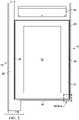
- FIGURE 1is an electronic display assembly 5 (hereinafter also the "assembly").
- the electronic display assembly 5comprises a front panel 10 that may cover the majority of the front surface of the assembly 5.
- the front panel 10may be transparent and is positioned in front of an electronic display 70, which is secured behind the front panel 10.
- the front panel 10is a touch screen.
- a perimeter wall 55may surround the front panel 10.
- a free standing display housing 15may surround the assembly 5 and may be configured to permit affixing the assembly 5 to the ground.
- the free standing display housing 15may be flag shaped.
- the free standing display housing 15may be sized and configured to be integrated into a bus shelter.
- the free standing display housing 15may comprise a post 20, an upper beam 25, and a base 30.
- the base 30may comprise select apertures 35, such as circular holes, that permit a fastener, such as a bolt, to pass through and thereby affix the base 30 to the ground.
- the number and location of the apertures 35 shownare merely an example.
- a bottom portion of post 20may be buried to affix the free standing display to the ground. In some embodiments, this may be accomplished by burying said bottom portion of post 20 in concrete.
- the free standing display housing 15 and related componentsmay be comprised of a metal, such as stainless steel or aluminum.
- the upper beam 25may further comprise a secondary display 40 that covers a majority of one side of the upper beam 25.
- this secondary display 40is a liquid crystal display (LCD).
- the secondary display 40may be a static display comprising an illumination device, such as a backlight, and a cavity to accommodate a static display, such as a poster.
- a pair of elongate members 50may extend from the top of the post 20.
- the elongate members 50may be configured to further secure the free standing display housing 15, and thereby the assembly 5, in place. Any number and shape of elongate members 50 is contemplated. In exemplary embodiments, these elongate members 50 may be sized and configured to be integrated with a bus shelter.
- the assembly 5comprises a gap 45 between the perimeter wall 55 and the front panel 10 configured to permit the flow of a fluid, such as ambient air, in and out of the assembly 5.
- a fluidsuch as ambient air
- the assembly 5is configured such that the upper half of the assembly 5 permits the intake of a fluid, while the lower half of the assembly 5 permits the exhaust of said fluid, as illustrated by the flow lines.
- Thisis only an example as other embodiments may be configured such that the upper half of the assembly 5 permits the exhaust of a fluid, while the lower half of the assembly 5 permits the intake of said fluid.
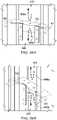
- FIGURE 2 and FIGURE 3illustrates the gap 45, further indicated by the cross hatched area which has been enlarged in order to show the detail, extends along the perimeter of the assembly 5.
- the gap 45comprises a buffer zone 46.
- the buffer zone 46is an area, between the ingestion and exhaust portions of the gap 45 that does not permit the flow of external air. In other embodiments, the buffer zone 46 may substantially limit the flow of external air.
- the gap 45is positioned around the perimeter of the front panel 10 but is not found within the buffer zones 46.
- the buffer zones 46are located near the vertical centerline of the display assembly 5 and typically there is a first buffer zone on the right hand side of the assembly with a second buffer zone on the left hand side of the assembly.
- the assembly 5comprises a rear panel 60 that covers a majority of the rear surface of assembly 5.
- a rear perimeter wall 54may surround the sides of rear panel 60. In exemplary embodiments not covered by the claims, the rear perimeter wall 54 may be substantially the same as the perimeter wall 55.
- the upper beam 25may further comprise a tertiary display 41 that may contain a backlight and graphic, similar to the secondary display 40.
- An illumination unit, such as a backlight,may be placed behind the rear panel 60.
- a cavitymay be located behind the rear surface of rear panel 60 and may be configured to accommodate a static display, such as a poster, placed within or behind the rear panel 60.
- an electronic display assembly(such as an LCD) may be placed behind the rear panel 60.
- the assembly 5comprises a rear gap 44 between the rear perimeter wall 54 and the rear panel 60 configured to permit the flow of a fluid, such as ambient air, in and out of the assembly 5.
- a fluidsuch as ambient air
- the assembly 5may be configured such that the upper half of the assembly 5 permits the intake of a fluid, while the lower half of the assembly 5 permits the exhaust of said fluid, as illustrated by the flow lines (but this could be reversed).
- ingestion and exhaustion of open loop fluid 400may not take place along select portions of the rear gap 44, such as the upper and lower edges. In other embodiments, ingestion and exhaustion of open loop fluid 400 may take place along the entirety of rear gap 44, with the possible exception of the buffer zones 46.
- FIGURE 5illustrates the front panel 10 removed, revealing that the electronic display 70 affixed behind front panel 10 and within perimeter wall 55.
- the assembly 5may further comprise a series of intake apertures 65 located above the electronic display 70, between the display 70 and the secondary display 40.
- the illustrated intake apertures 65are merely exemplary, any number and shape of intake apertures 65 is contemplated.
- the intake apertures 65may be configured to facilitate the ingestion of a fluid, such as ambient air, into an open loop that flows behind the electronic display 70.
- a pair of side interior channels 21 and 22may run the majority of the length of each side of the electronic display 70.
- FIGURE 6illustrates the rear panel 60 removed, revealing an interior rear panel 80 secured behind the rear panel 60.
- the interior rear panel 80may cover a majority of the rear surface of the assembly 5.
- the assemblymay contain a series of rear intake apertures 75 located above the interior rear panel 80 and sometimes within rear perimeter wall 54.
- the illustrated rear intake apertures 75are merely exemplary, any number and shape of said apertures 75 is contemplated. As will be explained in greater detail in subsequent figures, the apertures 75 may be configured to facilitate the ingestion of the open loop fluid.
- the assembly 5may further comprise a series of rear exhaust apertures 85 located below the interior rear panel 80 and sometimes within rear perimeter wall 54.
- the illustrated rear exhaust apertures 85are merely exemplary, any number and shape of rear exhaust apertures 85 is contemplated.
- the rear exhaust apertures 85may be configured to facilitate the exhaust of the open loop fluid.
- Fans 81are affixed behind interior rear panel 80 and above rear exhaust apertures 85. The fans 81 may be configured to control the flow of the open loop fluid. Any number of fans 81 is contemplated. In other embodiments, the fans 81 may be located at any number of locations along the open loop flow path, or any position between the intake 75 and exhaust apertures 85.
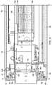
- FIGURE 7 and FIGURE 8illustrate the lower half of the assembly 5 and free standing display housing 15.
- a side beam 90may be located on the opposite side of post 20 and may run a majority of the length of the assembly 5.
- the side beam 90may be comprised of a metal and be configured to provide structural support and rigidity to the assembly 5.
- An electronics cavity 16may be placed within the interior of the assembly 5.
- An optional heat exchanger 100may be affixed within or near the electronics cavity 16.
- the heat exchanger 100may be a cross flow heat exchanger, but other types of heat exchangers can be used, especially counter flow heat exchangers and others.
- a series of electronic components 105may also be affixed within the electronics cavity 16.
- open loop fluid 400such as an external air
- Closed loop fluidsuch as a circulating gas 700 may circulate through the electronics cavity, as well as over and through electronic components 105, and through heat exchanger 100.
- open loop fluid 400exhausts the assembly 5 via gap 45 and optional rear gap 44.
- open loop fluidmay follow a zigzag path from a right side channel 19, out of the assembly 5.
- route shapesmay be utilized and are expressly contemplated.
- a backlight 106may be placed behind the electronic display 70 and is preferably a direct lit LED backlight, but other illumination sources can be used with the exemplary embodiments.
- a plate 104 or other substantially planar objectmay be placed behind the backlight 106 in order to create a channel 102 for accepting open loop fluid 400.
- the channel 102is sealed to prevent open loop fluid 400 from entering other portions of the display assembly, specifically the electronics compartment 16.
- FIGURE 9 and FIGURE 10illustrate the upper half of assembly 5 and free standing display housing 15, which are similar to the lower half as shown in FIG. 7 and FIG. 8 , respectively, with the exception of a pair of optional stiffeners 110.
- the optional stiffeners 110will be explained in greater detail in subsequent figures.
- open loop fluid 400may enter the assembly 5 via gap 45 and optional rear gap 44. As indicated by the flow lines, open loop fluid 400 may follow a zigzag path to the right side channel 19. Alternatively, other route shapes may be utilized and are expressly contemplated.
- FIGURE 11is a front plan view of the assembly of FIG. 1 and indicates section lines F-F, G-G, and H-H.
- FIGURE 12A and FIGURE 12Billustrates, as will be explained in greater detail in subsequent figures, a pair of channel septums 130 and a central septum 140 are preferably positioned substantially horizontally and near the vertical centerline of the assembly 5, although embodiments could also place them near the top or bottom of the assembly 5, away from the vertical centerline.
- Figure 12Ashows the area of the gap 45 (and optional rear gap 44) that is designated as the intake of the open loop fluid 400.
- the fan 81which is positioned to cause the flow of open loop fluid 400 into the portion of gap 45 (and optional rear gap 44) that is generally used as in intake for ambient air (filtered or unfiltered), down the left side interior channel 21 (intake channel), across/through channel 102, down the right side interior channel 22, and exhausting out of the portion of the gap 45 (and optional rear gap 44) that is used as an exhaust for the fluid 400.
- left and right side interior channels 21 and 22are optional as an alternative embodiment would include the following path for open loop fluid 400: into the portion of gap 45 (and optional rear gap 44) that is generally used as in intake for ambient air (filtered or unfiltered), across/through channel 102, and exhausting out of the portion of the gap 45 (and optional rear gap 44) that is used as an exhaust for the fluid 400.
- FIGURE 12Cis a top sectional view taken along section line H-H of FIG. 11 and indicates Detail R. In this embodiment, this figure shows the area of the gap 45 (and optional rear gap 44) that is designated as the exhaust of the open loop fluid 400.
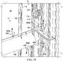
- FIGURE 13Aillustrates the ingestion of open loop fluid 400 via rear gap 44.
- the open loop fluid 400may pass through an optional door stiffener 115 via aperture 122.
- FIGURE 13Billustrates the assembly within the region of the buffer zone 46.
- the buffer zone 46comprises essentially an area at, near, or within the gap 45 (and rear gap 44) that contains one or more fluid-blocking plugs which are placed along the path of open loop fluid 400 so that it may not pass through in any substantial amount.
- the buffer zone 46would contain the channel septums 130 along with the central septum 140.
- the buffer zone 46may contain a plug that is positioned near or at the end of the gap 44.
- the buffer zoneis horizontal and is placed near the vertical centerline of the assembly 5, although it could be placed near the top or bottom of the assembly 5.
- the buffer zone 46should exist on both lateral sides of the assembly 5, as well as both on the front and rear of the assembly 5 (if using the rear gap 44) such that the buffer zone 46 blocks a portion of the front gap 45 (and the rear gap 44) on both the right and left sides of the assembly 5.
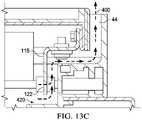
- FIGURE 13Cillustrates the exhaustion of open loop fluid 400 via rear gap 44.
- the open loop fluid 400may pass through a door stiffener 115 via aperture 122.
- FIGS 13A-13Cillustrate the rear gap 44
- the front gap 45has a similar orientation as to the rear gap 44. It has not been shown here as it would be substantially duplicative.
- FIGURE 14illustrates the combined areas of the gap 45 and the rear gap 44, as indicated by the cross hatched area.
- the cross hatched areaallows the flow of open loop fluid 400 either into or out of the gap 45 (and the rear gap 44).
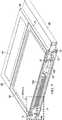
- FIGURE 15illustrates the assembly 5 in isolation from the free standing display housing 15.
- a door stiffener 120may be affixed immediately behind the front panel 10. In some embodiments not covered by the claims, the door stiffener 120 may be affixed to a rear surface of the front panel 10. The door stiffener 120 may run substantially the perimeter of the front panel 10.
- the door stiffener 120may be comprised of a metallic or other material suitably rigid to provide structural rigidity and strength to the assembly 5.
- the door stiffener 120may comprise a series of apertures 125 that permit the flow of open loop fluid 400.
- the illustrated door stiffener apertures 125are merely exemplary. Any number and shape of apertures 125 are contemplated.
- FIGURE 16illustrates the rear panel 60 in isolation.
- rear door stiffeners 115may be affixed around the perimeter edges of the rear panel 60, thereby framing rear panel 60.
- a door cavity 17is defined by the space between the rear panel 60, the interior surfaces of rear door stiffeners 115, and the interior rear panel 80 (not shown in the current figure).
- Open loop fluid 400 ingested via the rear gap 44may be considered open loop fluid 400b once it travels through the rear door stiffeners 115 via apertures 122 into the door cavity 17.
- the illustrated apertures 122are merely exemplary, any number and shape of apertures is contemplated.
- Optional stiffeners 110 in the form of elongate membersmay extend substantially the length of the rear panel 60.
- the optional stiffeners 110may be comprised of a metal, a polymer, or other material suitably rigid to provide structural rigidity and strength to the rear panel 60.
- the optional stiffeners 110may comprise a series of apertures 135 that facilitate open loop fluid 400b to flow through the optional stiffeners 110.
- the illustrated optional stiffeners 110 and the apertures 135are merely exemplary, any number and shape of the optional stiffeners 110 and the apertures 135 is contemplated.
- open loop fluid 400bThe portion of the open loop fluid 400 traveling in the door cavity 17 is referred to as open loop fluid 400b.
- open loop fluid 400bmay pass behind the interior panel 80 and be ingested via the intake apertures 75 in order to be directed towards the channel 102.
- the fluid 400bwould flow through intake apertures 75 and be directed into left side channel 18, which distributes the fluid 400b across the channel 102, and exhausted out of right side channel 19.
- FIGURE 17illustrates, via flow lines, the circulation of open loop fluid 400a through the front and rear of assembly 5.
- Open loop fluidmay be ingested via the gap 45, travel through the door stiffener 120 via the apertures 125 and travel vertically through the right side channel 19 sometimes defined in part by the right side interior channel 22 and side beam 90.
- the open loop fluid 400amay be ingested via the rear gap 44, travel through the door stiffener 115 via the apertures 122, through optional stiffeners 110 via aperture 135, and enter the right side channel 19.
- a similar routemay be taken whereby the open loop fluid ultimately enters a left side channel 18 sometimes defined in part by the left side interior channel 21 and post 20.
- a substantially identical flow path in reversemay be taken for exhaustion of the open loop fluid at on the opposite end of the assembly 5.
- ingestiontakes place in the upper half or assembly 5 and exhaustion takes place in the lower half of assembly 5.
- ingestiontakes place in the lower half and exhaustion in the upper half of the assembly 5.
- ingestionmay take place on the right side while exhaustion takes place on the left side with the buffer zone 46 placed at the top and bottom edges of the assembly to prevent cross inhalation of the two flow paths.
- FIGURE 18illustrates an exemplary flow path for the open loop fluid 400 after being ingested via the gap 45 and the rear gap 44.
- the open loop fluid 400 which is ingested via the rear gap 44may travel along the door cavity 17 between the optional door stiffeners 110 and can be referred to as the open loop fluid 400b.
- the open loop fluid 400bmay then travel vertically along the rear interior panel 80 and be ingested via the rear intake apertures 75.
- Other portion of open loop fluid 400may travel along the left side channel 18 and the right side channel 19 and be referred to as the open loop fluid 400a.
- the open loop fluid 400aAfter traveling vertically through the side channels 18 and 19, the open loop fluid 400a may travel over the top of said channels and be ingested via the intake apertures 75.
- the open loop fluid 400may be ingested via the gap 45, travel through the door stiffener apertures 125 below front panel 10, and be ingested via the intake apertures 65.
- FIGURE 19Aillustrates a rear perspective view of the assembly of FIG. 1 shown in isolation from the free standing display 15 and indicating Detail S.
- FIGURE 19Billustrates a front perspective view of the assembly of FIG. 1 shown in isolation from the free standing display 15 and indicating Detail T.
- FIGURE 20illustrates that the portion of open loop fluid 400 traveling in the right side channel 19 is referred to as open loop fluid 400a.
- the open loop fluid 400amay travel inside the right side channel 19, over the top of the right side interior channel 22, and into the intakes apertures 75.
- FIGURE 21similar to FIG. 20 but shown from a front perspective, illustrates that the portion of open loop fluid 400 traveling in the left side channel 18 is referred to as open loop fluid 400a.
- the open loop fluid 400amay travel inside the left side channel 18, over the top of the left side interior channel 21, and into the intakes apertures 65.
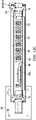
- FIGURE 22is bottom perspective section view taken along section line B-B of FIG. 4 .
- One or more circulating fans 32are used to force circulating gas 700 across the electronic components and through the closed loop gas pathways of the heat exchanger 100, as well as between the electronic display 70 and the front panel 10, forming a closed loop.
- the circulating gas 700passes through the opening within the pass through gasket 200 while the open loop fluid 400 travels around the pass through gasket, substantially ensuring that the open loop fluid 400 and circulating gas 700 do not mix.
- This designcan be flipped however, where , the circulating gas 700 travels around the pass through gasket 200 while the external air 400 travels through the pass through gasket 200.
- a portion of the flow of open loop fluid 400is shown traversing the left side interior channel 21 and passing by the cross through gasket 200 in order to enter the channel 102 that runs behind the electronic display 70 (here behind the backlight 106).
- the channel102is preferably defined as the space between the rear surface of the electronic display 70 (here behind the backlight 106) and a plate 104.
- a preferably corrugated and preferably continuous heat sinkis ideally placed within the channel in order to facilitate the conductive transfer of heat from the electronic display 101 to the continuous heat sink, to be removed by convection with the open loop fluid 400.
- the heat exchanger 100preferably contains a plurality of layers that define channels that contains either circulating gas 700 or open loop fluid 400.
- the circulating gas 700is not permitted to mix with the open loop fluid 400.
- the flow of open loop fluid 400travels through the channel 102 and again passes around the pass through gasket 200 to enter the left side interior channel 22, eventually being directed out of the portions of the gap 45 (and the optional rear gap 44) which have been designated for exhaustion of the fluid 400.
- the circulating gas 700is shown exiting the heat exchanger 100 and passing through the opening within the pass through gasket 200 and then between the electronic display 70 and the front panel 10.
- the heat exchanger 100would be a cross-flow heat exchanger.
- the heat exchanger 100may be a cross-flow, parallel flow, or counter-flow heat exchanger.
- the heat exchanger 100would be comprised of a plurality of stacked layers of thin plates.
- the platesmay have a corrugated, honeycomb, or tubular design, where a plurality of channels/pathways/tubes travel down the plate length-wise.
- the platesmay be stacked such that the directions of the pathways are alternated with each adjacent plate, so that each plate's pathways are substantially perpendicular to the pathways of the adjacent plates.
- external air or circulating gasmay enter an exemplary heat exchanger only through plates whose channels or pathways travel parallel to the path of the gas. Because the plates are alternated, the circulating gas and open loop fluid may travel in plates which are adjacent to one another and heat may be transferred between the two gases without mixing the gases themselves (if the heat exchanger is adequately sealed, which is preferable).
- an open channelmay be placed in between a pair of corrugated, honeycomb, or tubular plates.
- the open channelmay travel in a direction which is perpendicular to the pathways of the adjacent plates.
- This open channelmay be created by running two strips of material or tape (esp. very high bond (VHB) tape) between two opposite edges of the plates in a direction that is perpendicular to the direction of the pathways in the adjacent plates.
- VHBvery high bond
- cross-flow heat exchangerscould include a plurality of tubes which contain the first gas and travel perpendicular to the path of the second gas. As the second gas flows over the tubes containing the first gas, heat is exchanged between the two gases.
- cross-flow heat exchangersthere are many types of cross-flow heat exchangers and any type would work with the embodiments herein.
- An exemplary heat exchangermay have plates where the sidewalls have a relatively low thermal resistance so that heat can easily be exchanged between the two gases.
- a number of materialscan be used to create the heat exchanger.
- the material usedshould be corrosion resistant, rot resistant, light weight, and inexpensive.
- Metalsare typically used for heat exchangers because of their high thermal conductivity and would work with these embodiments.
- plastics and compositescan also satisfy the thermal conditions for electronic displays.
- An exemplary embodimentwould utilize polypropylene as the material for constructing the plates for the heat exchanger. It has been found that although polypropylene may seem like a poor thermal conductor, the large amount of surface area relative to a small sidewall thickness, results in an overall thermal resistance that is low.
- an exemplary heat exchangerwould be made of plastic and would thus produce a display assembly that is thin and lightweight.
- corrugated plasticmay be used for each plate layer where they are stacked together in alternating fashion (i.e. each adjacent plate has channels which travel in a direction perpendicular to the surrounding plates).
- the electronic display 70would be a direct LED backlit LCD where the LED backlight would contain a plurality of LEDs mounted on a thermally conductive substrate (preferably a metal core PCB).
- the rear surface of the LED backlightwould preferably contain a thermally conductive plate which may be in conductive thermal communication with the channel 102.
- the circulating gas 700 and open loop fluid 400can be any number of gaseous matters. In some embodiments, air may be used as the gas for all. Preferably, because the circulating gas 700 travels in front of the electronic display 70 it should be substantially clear, so that it will not affect the appearance of the image to a viewer.
- the circulating gas 700should also preferably be substantially free of contaminates and/or particulate (ex. dust, dirt, pollen, water vapor, smoke, etc.) in order to prevent an adverse effect on the image quality and/or damage to the internal electronic components. Generally speaking, exemplary embodiments would utilize ambient air as the open loop fluid 400.
- the cooling systemmay run continuously. However, if desired, temperature sensing devices may be incorporated within the electronic display to detect when temperatures have reached a predetermined threshold value. In such a case, the various cooling fans may be selectively engaged when the temperature in the display reaches a predetermined value. Predetermined thresholds may be selected and the system may be configured to advantageously keep the display within an acceptable temperature range. Typical thermostat assemblies can be used to accomplish this task. Thermocouples may be used as the temperature sensing devices.
- FIGURES 23 through 25illustrate a central septum 140 which is preferably positioned substantially horizontally and near the vertical centerline of the assembly 5, although it could also be placed near the top or bottom of the assembly 5, away from the vertical centerline that extends along substantially the midline of the front surface of the rear panel 60.
- a right channel septum 130extends substantially along the midline of the right side interior edge of the free standing display housing 15 such that it is generally aligned with the central septum 140.
- a left channel septum 130may be affixed on the left side interior edge of the assembly 5 such that it is aligned with the central septum 140.
- the central septum 140, the right channel septum 130, and the left channel septum 130may be configured to substantially divide the door cavity 17 into an upper and lower half.
- the horizontal partitionmay be configured such that it creates a substantially air-tight seal between the upper and lower halves of the door cavity 17.
- the horizontal partitionmay further comprise an expandable material, such as polyurethane foam, utilized in conjunction with the horizontal partition to provide the airtight seal between the upper and lower halves.
- the central septum 140may be comprised of a sufficiently flexible material, such as a polymer, to create an airtight seal in the door cavity 17.
- the central septum 140may be comprised of a rigid material.
- the right channel septum 130 and the left channel septum 130may be rigid.
- the open loop fluid 400may be ingested via the gap 45 (and optional rear gap 44) in the upper half of the assembly 5. Said open loop fluid 400a may travel along the right side channel 19 until a portion of said fluid reaches the right channel septum 130 and is prevented from traveling beyond. Similarly, the open loop fluid 400a may travel along the left side channel 18 until a portion of said fluid reaches the left side channel septum 130. Said portions of the open loop fluid may be forced to return vertically in the opposite direction and circulate through the upper half of right side channel 19 and the left side channel 18, respectively, until eventually being ingested via the intake apertures 65 and 75, as discussed in the previous figures.
- open loop fluid 400b which travels along the door cavity 17may travel vertically until a portion of said fluid 400b reaches central septum 140 and is prevented from traveling beyond.
- fluid 400b which has been ingested(but has not traveled through the heat exchanger 100 or the channel 102) cannot mix with the fluid 400b which has travelled through the heat exchanger 100 or the channel 102 and needs to be exhausted out of the gap 45 (and optional rear gap 44).
- the open loop fluid 400may circulate through the optional heat exchanger 100 until eventually being exhausted via the exhaust apertures 85.
- the open loop fluid 400may then eventually return to the right side channel 19 or the left side channel 18 and travel vertically therein.
- the right channel septum 130 and the left channel septum 130, respectively,may prevent said open loop fluid from traveling beyond the midline of assembly 5 and thereby prevent the open loop fluid from each half of the assembly 5 from becoming mixed. That is, open loop fluid not yet ingested via the intake apertures 65 and 75 may not be mixed with open loop fluid already ingested via said intake apertures 65 and 75.
- the open loop fluid encountering the right side septum 130 and the left side septum 130, respectively,may be forced to return vertically in the opposite direction until eventually being exhausted from the assembly 5 via the gap 45 (and optional rear gap 44).
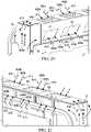
- FIGURE 26A and FIGURE 26Billustrate exemplary embodiments of the channel septums 130.
- a portion of the channel septums 141may be adjustable such that (if desired) a portion of the open loop fluid 400a may be permitted to pass by the channel septums 130, thereby permitting a limited amount of mixing between the ingestion and exhaustion open loop fluids.
- a second portion of the channel septums 142may be static, such that they may not be adjusted and provide a substantially air-tight seal such that ingestion and exhaustion open loop fluids may not be mixed.
- the entirety of the channel septums 130may be adjustable. In still other embodiments, the entirety of the channel septums 130 may be static.
- embodimentsmay be used in conjunction with any of the following electronic image assemblies: LCD (all types), light emitting diode (LED), organic light emitting diode (OLED), field emitting display (FED), light emitting polymer (LEP), organic electro luminescence (OEL), plasma displays, and any other thin panel electronic image assembly.
- LCDall types
- LEDlight emitting diode
- OLEDorganic light emitting diode
- FEDfield emitting display
- LEPlight emitting polymer
- OELorganic electro luminescence
- plasma displaysany other thin panel electronic image assembly.
- the systemmay be well suited for use with full color, flat panel OLED displays.
- Exemplary embodimentsmay also utilize large (55 inches or more) LED backlit, high definition liquid crystal displays (LCD). While the embodiments described herein are well suited for outdoor environments, they may also be appropriate for indoor applications (e.g., factory/industrial environments, spas, locker rooms) where thermal stability of the display may be at risk.
- electronic displayscan be oriented in a portrait manner or landscape manner and either can be used with the embodiments herein.
- cooling loopsthat are shown in the figures may be shown in a horizontal or vertical arrangement but it is clearly contemplated that this can be reversed or changed depending on the particular embodiment.
- the open loopmay run horizontally or vertically and in a clockwise or counterclockwise direction.
- the open loopmay also be horizontal or vertical and can run left to right, right to left, and top to bottom, or bottom to top.
Landscapes
- Engineering & Computer Science (AREA)
- Microelectronics & Electronic Packaging (AREA)
- Physics & Mathematics (AREA)
- Thermal Sciences (AREA)
- Devices For Indicating Variable Information By Combining Individual Elements (AREA)
- Cooling Or The Like Of Electrical Apparatus (AREA)
- Heat-Exchange Devices With Radiators And Conduit Assemblies (AREA)
Description
- The present invention relates to mounting and cooling systems for electronic displays.
- Electronic displays are sometimes used in outdoor environments or other areas where the surrounding temperatures may be high or there may be other sources of heat such as solar loading causing the temperatures within the display to rise. However, some portions of the display can be difficult to cool as simply ingesting ambient air into some portions of the display can introduce dust and contaminates into sensitive portions of the display, which can lead to premature failures.
WO 2014/149773 ,US 2013/201685 ,US 2011/072697 andUS 2012/106081 disclose examples of known electronic displays. - According to the present invention there is provided an electronic display assembly as claimed in claim 1. Original and preferred features of the invention are defined in the dependent claims.
- In addition to the features mentioned above, other aspects of the present invention will be readily apparent from the following descriptions of the drawings and embodiments, wherein like reference numerals across the several views refer to identical or equivalent features, and wherein:
FIGURE 1 is a front perspective view of an exemplary embodiment of the electronic display assembly housed in a free standing housing, and indicating section line A-A and Detail A.FIGURE 2 is a front elevation view of the embodiment shown inFIG. 1 and indicating Detail N.FIGURE 3 is a detailed front elevation view of Detail N shown inFIG. 2 .FIGURE 4 is a rear perspective view of the exemplary embodiment ofFIG. 1 , and indicating section line B-B as well as Detail C.FIGURE 5 is a front perspective view of Detail A shown inFIG. 1 , shown with a front panel removed.FIGURE 6 is a rear perspective view of the exemplary embodiment shown inFIG. 1 , where a rear panel has been removed, and indicating Detail D and Detail E.FIGURE 7 is a top perspective section view taken along section line A-A ofFIG. 1 , and indicating Detail F.FIGURE 8 is a top plan section view of Detail F shown inFIG. 7 .FIGURE 9 is bottom perspective section view taken along section line B-B ofFIG. 4 , and indicating Detail K.FIGURE 10 is a bottom plan section view of Detail K shown inFIG. 9 , and indicating Detail L.FIGURE 11 is a front plan view of the exemplary embodiment shown inFIG.1 and indicating section lines F-F, G-G, and H-H.FIGURE 12A is a top plan section view taken along section line F-F ofFIG. 11 , and indicating Detail O and Detail P.FIGURE 12B is a top plan section view taken along section line G-G ofFIG. 11 , and indicating Detail Q.FIGURE 12C is a top plan section view taken along section line H-H ofFIG. 11 , and indicating Detail R.FIGURE 13A is a top plan detailed section view of Detail O inFIG. 12A .FIGURE 13B is a top plan detailed section view of Detail Q inFIG. 12B .FIGURE 13C is a top plan detailed section view of Detail R inFIG. 12C .FIGURE 14 is a top plan detailed section view of Detail P inFIG. 12A .FIGURE 15 is a rear perspective view of Detail D shown inFIG. 6 , shown with the free standing display housing removed.FIGURE 16 is a front perspective view of Detail C shown inFIG. 4 of the rear panel, shown in isolation from the surrounding components.FIGURE 17 is a bottom plan section view of Detail L shown inFIG. 10 .FIGURE 18 is a rear perspective view of Detail E shown inFIG. 6 , shown with the free standing display housing removed.FIGURE 19A is a rear perspective view of the assembly ofFIG. 1 , shown with the free standing display housing removed, and indicating Detail S.FIGURE 19B is a front perspective view of the assembly ofFIG. 1 , shown with the free standing display housing and front panel removed, and indicating Detail T.FIGURE 20 is a rear perspective detail view of Detail S shown inFIG. 19A .FIGURE 21 is a front perspective detail view of Detail T shown inFIG. 19B .FIGURE 22 is bottom perspective section view taken along section line B-B ofFIG. 4 FIGURE 23 is a front perspective view of the assembly ofFIG. 1 showing only the rear panel, free standing display housing, and a select portion of the display assembly in isolation from all other surrounding components.FIGURE 24 is a top view of the assembly ofFIG. 1 , showing only the rear panel and select portions of the display assembly in isolation from all other surrounding components, and indicating detail M.FIGURE 25 is a front perspective view of Detail M shown inFIG. 23 .FIGURE 26A is a front perspective view of a septum shown with only the free standing display housing and select portions of the display assembly in isolation from all other surrounding components.FIGURE 26B is another front perspective view of the septum, again shown with only the free standing display housing and select portions of the display assembly in isolation from all other surrounding components.- The invention is described more fully hereinafter with reference to the accompanying drawings, in which embodiments of the invention are shown. This invention may, however, be embodied in many different forms as long as they fall under the scope of the appended claims, and should not be construed as limited to the embodiments set forth herein. Rather, these embodiments are provided so that this disclosure will be thorough and complete, and will fully convey the scope of the invention to those skilled in the art. In the drawings, the size and relative sizes of layers and regions may be exaggerated for clarity.
- The terminology used herein is for the purpose of describing particular embodiments only and is not intended to be limiting of the invention. As used herein, the singular forms "a", "an" and "the" are intended to include the plural forms as well, unless the context clearly indicates otherwise. It will be further understood that the terms "comprises" and/or "comprising," when used in this specification, specify the presence of stated features, integers, steps, operations, elements, and/ or components, but do not preclude the presence or addition of one or more other features, integers, steps, operations, elements, components, and/or groups thereof. Embodiments of the invention are described herein with reference to illustrations that are schematic illustrations of idealized embodiments (and intermediate structures) of the invention. As such, variations from the shapes of the illustrations as a result, for example, of manufacturing techniques and/or tolerances, are to be expected. Thus, embodiments of the invention should not be construed as limited to the particular shapes of regions illustrated herein but are to include deviations in shapes that result, for example, from manufacturing.
- Unless otherwise defined, all terms (including technical and scientific terms) used herein have the same meaning as commonly understood by one of ordinary skill in the art to which this invention belongs. It will be further understood that terms, such as those defined in commonly used dictionaries, should be interpreted as having a meaning that is consistent with their meaning in the context of the relevant art and will not be interpreted in an idealized or overly formal sense unless expressly so defined herein.
FIGURE 1 is an electronic display assembly 5 (hereinafter also the "assembly"). Theelectronic display assembly 5 comprises afront panel 10 that may cover the majority of the front surface of theassembly 5. Thefront panel 10 may be transparent and is positioned in front of anelectronic display 70, which is secured behind thefront panel 10. In exemplary embodiments, thefront panel 10 is a touch screen. Aperimeter wall 55 may surround thefront panel 10.- A free
standing display housing 15 may surround theassembly 5 and may be configured to permit affixing theassembly 5 to the ground. The freestanding display housing 15 may be flag shaped. In still other embodiments, the freestanding display housing 15 may be sized and configured to be integrated into a bus shelter. - The free
standing display housing 15 may comprise apost 20, anupper beam 25, and abase 30. In exemplary embodiments, thebase 30 may compriseselect apertures 35, such as circular holes, that permit a fastener, such as a bolt, to pass through and thereby affix the base 30 to the ground. The number and location of theapertures 35 shown are merely an example. A bottom portion ofpost 20 may be buried to affix the free standing display to the ground. In some embodiments, this may be accomplished by burying said bottom portion ofpost 20 in concrete. The freestanding display housing 15 and related components may be comprised of a metal, such as stainless steel or aluminum. - The
upper beam 25 may further comprise asecondary display 40 that covers a majority of one side of theupper beam 25. In exemplary embodiments thissecondary display 40 is a liquid crystal display (LCD). In other embodiments, thesecondary display 40 may be a static display comprising an illumination device, such as a backlight, and a cavity to accommodate a static display, such as a poster. - A pair of
elongate members 50 may extend from the top of thepost 20. Theelongate members 50 may be configured to further secure the freestanding display housing 15, and thereby theassembly 5, in place. Any number and shape ofelongate members 50 is contemplated. In exemplary embodiments, theseelongate members 50 may be sized and configured to be integrated with a bus shelter. - As discussed in greater detail in the subsequent figures, the
assembly 5 comprises agap 45 between theperimeter wall 55 and thefront panel 10 configured to permit the flow of a fluid, such as ambient air, in and out of theassembly 5. In other embodiments, theassembly 5 is configured such that the upper half of theassembly 5 permits the intake of a fluid, while the lower half of theassembly 5 permits the exhaust of said fluid, as illustrated by the flow lines. This is only an example as other embodiments may be configured such that the upper half of theassembly 5 permits the exhaust of a fluid, while the lower half of theassembly 5 permits the intake of said fluid. FIGURE 2 andFIGURE 3 illustrates thegap 45, further indicated by the cross hatched area which has been enlarged in order to show the detail, extends along the perimeter of theassembly 5. Thegap 45 comprises abuffer zone 46. Thebuffer zone 46 is an area, between the ingestion and exhaust portions of thegap 45 that does not permit the flow of external air. In other embodiments, thebuffer zone 46 may substantially limit the flow of external air. In an exemplary embodiment, thegap 45 is positioned around the perimeter of thefront panel 10 but is not found within thebuffer zones 46. In an exemplary embodiment, thebuffer zones 46 are located near the vertical centerline of thedisplay assembly 5 and typically there is a first buffer zone on the right hand side of the assembly with a second buffer zone on the left hand side of the assembly.- In
FIGURE 4 theassembly 5 comprises arear panel 60 that covers a majority of the rear surface ofassembly 5. Arear perimeter wall 54 may surround the sides ofrear panel 60. In exemplary embodiments not covered by the claims, therear perimeter wall 54 may be substantially the same as theperimeter wall 55. Theupper beam 25 may further comprise atertiary display 41 that may contain a backlight and graphic, similar to thesecondary display 40. An illumination unit, such as a backlight, may be placed behind therear panel 60. A cavity may be located behind the rear surface ofrear panel 60 and may be configured to accommodate a static display, such as a poster, placed within or behind therear panel 60. In alternate embodiments, an electronic display assembly (such as an LCD) may be placed behind therear panel 60. - As discussed in greater detail in the subsequent figures, similarly to
FIG. 1 theassembly 5 comprises arear gap 44 between therear perimeter wall 54 and therear panel 60 configured to permit the flow of a fluid, such as ambient air, in and out of theassembly 5. In exemplary embodiments, theassembly 5 may be configured such that the upper half of theassembly 5 permits the intake of a fluid, while the lower half of theassembly 5 permits the exhaust of said fluid, as illustrated by the flow lines (but this could be reversed). - In exemplary embodiments of the present invention, ingestion and exhaustion of
open loop fluid 400 may not take place along select portions of therear gap 44, such as the upper and lower edges. In other embodiments, ingestion and exhaustion ofopen loop fluid 400 may take place along the entirety ofrear gap 44, with the possible exception of thebuffer zones 46. FIGURE 5 illustrates thefront panel 10 removed, revealing that theelectronic display 70 affixed behindfront panel 10 and withinperimeter wall 55. Theassembly 5 may further comprise a series ofintake apertures 65 located above theelectronic display 70, between thedisplay 70 and thesecondary display 40. The illustratedintake apertures 65 are merely exemplary, any number and shape ofintake apertures 65 is contemplated. Theintake apertures 65 may be configured to facilitate the ingestion of a fluid, such as ambient air, into an open loop that flows behind theelectronic display 70. A pair of sideinterior channels electronic display 70.FIGURE 6 illustrates therear panel 60 removed, revealing an interiorrear panel 80 secured behind therear panel 60. The interiorrear panel 80 may cover a majority of the rear surface of theassembly 5. The assembly may contain a series ofrear intake apertures 75 located above the interiorrear panel 80 and sometimes withinrear perimeter wall 54. The illustratedrear intake apertures 75 are merely exemplary, any number and shape of saidapertures 75 is contemplated. As will be explained in greater detail in subsequent figures, theapertures 75 may be configured to facilitate the ingestion of the open loop fluid.- Similarly, the
assembly 5 may further comprise a series ofrear exhaust apertures 85 located below the interiorrear panel 80 and sometimes withinrear perimeter wall 54. The illustratedrear exhaust apertures 85 are merely exemplary, any number and shape ofrear exhaust apertures 85 is contemplated. As will be explained in greater detail in subsequent figures, therear exhaust apertures 85 may be configured to facilitate the exhaust of the open loop fluid.Fans 81 are affixed behind interiorrear panel 80 and aboverear exhaust apertures 85. Thefans 81 may be configured to control the flow of the open loop fluid. Any number offans 81 is contemplated. In other embodiments, thefans 81 may be located at any number of locations along the open loop flow path, or any position between theintake 75 andexhaust apertures 85. FIGURE 7 andFIGURE 8 illustrate the lower half of theassembly 5 and freestanding display housing 15. Aside beam 90 may be located on the opposite side ofpost 20 and may run a majority of the length of theassembly 5. Theside beam 90 may be comprised of a metal and be configured to provide structural support and rigidity to theassembly 5. Anelectronics cavity 16 may be placed within the interior of theassembly 5. Anoptional heat exchanger 100 may be affixed within or near theelectronics cavity 16. In exemplary embodiments theheat exchanger 100 may be a cross flow heat exchanger, but other types of heat exchangers can be used, especially counter flow heat exchangers and others. A series ofelectronic components 105 may also be affixed within theelectronics cavity 16. As will be explained in greater detail in subsequent figures,open loop fluid 400, such as an external air, may circulate through theheat exchanger 100. Closed loop fluid, such as a circulatinggas 700 may circulate through the electronics cavity, as well as over and throughelectronic components 105, and throughheat exchanger 100.- As will be explained in greater detail in subsequent figures,
open loop fluid 400 exhausts theassembly 5 viagap 45 and optionalrear gap 44. As indicated by the flow lines, open loop fluid may follow a zigzag path from aright side channel 19, out of theassembly 5. Alternatively, other route shapes may be utilized and are expressly contemplated. - When using a liquid crystal display as the
electronic display 70, abacklight 106 may be placed behind theelectronic display 70 and is preferably a direct lit LED backlight, but other illumination sources can be used with the exemplary embodiments. Aplate 104 or other substantially planar object may be placed behind thebacklight 106 in order to create achannel 102 for acceptingopen loop fluid 400. Preferably, thechannel 102 is sealed to preventopen loop fluid 400 from entering other portions of the display assembly, specifically theelectronics compartment 16. FIGURE 9 andFIGURE 10 illustrate the upper half ofassembly 5 and freestanding display housing 15, which are similar to the lower half as shown inFIG. 7 andFIG. 8 , respectively, with the exception of a pair ofoptional stiffeners 110. Theoptional stiffeners 110 will be explained in greater detail in subsequent figures. As will be explained in greater detail in subsequent figures,open loop fluid 400 may enter theassembly 5 viagap 45 and optionalrear gap 44. As indicated by the flow lines,open loop fluid 400 may follow a zigzag path to theright side channel 19. Alternatively, other route shapes may be utilized and are expressly contemplated.FIGURE 11 is a front plan view of the assembly ofFIG. 1 and indicates section lines F-F, G-G, and H-H.FIGURE 12A andFIGURE 12B illustrates, as will be explained in greater detail in subsequent figures, a pair ofchannel septums 130 and acentral septum 140 are preferably positioned substantially horizontally and near the vertical centerline of theassembly 5, although embodiments could also place them near the top or bottom of theassembly 5, away from the vertical centerline.- In this embodiment,
Figure 12A shows the area of the gap 45 (and optional rear gap 44) that is designated as the intake of theopen loop fluid 400. - Also shown in these figures, as well as
Figure 12C is thefan 81, which is positioned to cause the flow ofopen loop fluid 400 into the portion of gap 45 (and optional rear gap 44) that is generally used as in intake for ambient air (filtered or unfiltered), down the left side interior channel 21 (intake channel), across/throughchannel 102, down the right sideinterior channel 22, and exhausting out of the portion of the gap 45 (and optional rear gap 44) that is used as an exhaust for thefluid 400. It should be noted that the left and right sideinterior channels channel 102, and exhausting out of the portion of the gap 45 (and optional rear gap 44) that is used as an exhaust for thefluid 400. FIGURE 12C is a top sectional view taken along section line H-H ofFIG. 11 and indicates Detail R. In this embodiment, this figure shows the area of the gap 45 (and optional rear gap 44) that is designated as the exhaust of theopen loop fluid 400.FIGURE 13A illustrates the ingestion ofopen loop fluid 400 viarear gap 44. Theopen loop fluid 400 may pass through anoptional door stiffener 115 viaaperture 122.FIGURE 13B illustrates the assembly within the region of thebuffer zone 46. Thebuffer zone 46 comprises essentially an area at, near, or within the gap 45 (and rear gap 44) that contains one or more fluid-blocking plugs which are placed along the path ofopen loop fluid 400 so that it may not pass through in any substantial amount. In exemplary embodiments, thebuffer zone 46 would contain thechannel septums 130 along with thecentral septum 140. In some embodiments, rather than placing thechannel septums 130 within the right andleft side channels buffer zone 46 may contain a plug that is positioned near or at the end of thegap 44. Generally speaking, the buffer zone is horizontal and is placed near the vertical centerline of theassembly 5, although it could be placed near the top or bottom of theassembly 5.- It is notable that the
buffer zone 46 should exist on both lateral sides of theassembly 5, as well as both on the front and rear of the assembly 5 (if using the rear gap 44) such that thebuffer zone 46 blocks a portion of the front gap 45 (and the rear gap 44) on both the right and left sides of theassembly 5. FIGURE 13C illustrates the exhaustion ofopen loop fluid 400 viarear gap 44. Theopen loop fluid 400 may pass through adoor stiffener 115 viaaperture 122.- It should be noted that although
Figures 13A-13C illustrate therear gap 44, in an exemplary embodiment thefront gap 45 has a similar orientation as to therear gap 44. It has not been shown here as it would be substantially duplicative. FIGURE 14 illustrates the combined areas of thegap 45 and therear gap 44, as indicated by the cross hatched area. In exemplary embodiments, outside of thebuffer zone 46, the cross hatched area allows the flow ofopen loop fluid 400 either into or out of the gap 45 (and the rear gap 44).FIGURE 15 illustrates theassembly 5 in isolation from the freestanding display housing 15. Adoor stiffener 120 may be affixed immediately behind thefront panel 10. In some embodiments not covered by the claims, thedoor stiffener 120 may be affixed to a rear surface of thefront panel 10. Thedoor stiffener 120 may run substantially the perimeter of thefront panel 10. Thedoor stiffener 120 may be comprised of a metallic or other material suitably rigid to provide structural rigidity and strength to theassembly 5. Thedoor stiffener 120 may comprise a series ofapertures 125 that permit the flow ofopen loop fluid 400. The illustrateddoor stiffener apertures 125 are merely exemplary. Any number and shape ofapertures 125 are contemplated.FIGURE 16 illustrates therear panel 60 in isolation. In exemplary embodiments,rear door stiffeners 115 may be affixed around the perimeter edges of therear panel 60, thereby framingrear panel 60. Adoor cavity 17 is defined by the space between therear panel 60, the interior surfaces ofrear door stiffeners 115, and the interior rear panel 80 (not shown in the current figure).Open loop fluid 400 ingested via therear gap 44 may be consideredopen loop fluid 400b once it travels through therear door stiffeners 115 viaapertures 122 into thedoor cavity 17. The illustratedapertures 122 are merely exemplary, any number and shape of apertures is contemplated.Optional stiffeners 110 in the form of elongate members may extend substantially the length of therear panel 60. Theoptional stiffeners 110 may be comprised of a metal, a polymer, or other material suitably rigid to provide structural rigidity and strength to therear panel 60. Theoptional stiffeners 110 may comprise a series ofapertures 135 that facilitateopen loop fluid 400b to flow through theoptional stiffeners 110. The illustratedoptional stiffeners 110 and theapertures 135 are merely exemplary, any number and shape of theoptional stiffeners 110 and theapertures 135 is contemplated.- The portion of the
open loop fluid 400 traveling in thedoor cavity 17 is referred to asopen loop fluid 400b. As shown,open loop fluid 400b may pass behind theinterior panel 80 and be ingested via theintake apertures 75 in order to be directed towards thechannel 102. In an exemplary embodiment, the fluid 400b would flow throughintake apertures 75 and be directed intoleft side channel 18, which distributes the fluid 400b across thechannel 102, and exhausted out ofright side channel 19.FIGURE 17 illustrates, via flow lines, the circulation ofopen loop fluid 400a through the front and rear ofassembly 5. Open loop fluid may be ingested via thegap 45, travel through thedoor stiffener 120 via theapertures 125 and travel vertically through theright side channel 19 sometimes defined in part by the right sideinterior channel 22 andside beam 90. Similarly, theopen loop fluid 400a may be ingested via therear gap 44, travel through thedoor stiffener 115 via theapertures 122, throughoptional stiffeners 110 viaaperture 135, and enter theright side channel 19. On the opposite side of theassembly 5, a similar route may be taken whereby the open loop fluid ultimately enters aleft side channel 18 sometimes defined in part by the left sideinterior channel 21 andpost 20. - A substantially identical flow path in reverse may be taken for exhaustion of the open loop fluid at on the opposite end of the
assembly 5. Again, in exemplary embodiments, ingestion takes place in the upper half orassembly 5 and exhaustion takes place in the lower half ofassembly 5. In other embodiments, ingestion takes place in the lower half and exhaustion in the upper half of theassembly 5. In still other embodiments, ingestion may take place on the right side while exhaustion takes place on the left side with thebuffer zone 46 placed at the top and bottom edges of the assembly to prevent cross inhalation of the two flow paths. FIGURE 18 illustrates an exemplary flow path for theopen loop fluid 400 after being ingested via thegap 45 and therear gap 44. Theopen loop fluid 400 which is ingested via therear gap 44 may travel along thedoor cavity 17 between theoptional door stiffeners 110 and can be referred to as theopen loop fluid 400b. Theopen loop fluid 400b may then travel vertically along the rearinterior panel 80 and be ingested via therear intake apertures 75. Other portion ofopen loop fluid 400 may travel along theleft side channel 18 and theright side channel 19 and be referred to as theopen loop fluid 400a. After traveling vertically through theside channels open loop fluid 400a may travel over the top of said channels and be ingested via theintake apertures 75. Similarly, theopen loop fluid 400 may be ingested via thegap 45, travel through thedoor stiffener apertures 125 belowfront panel 10, and be ingested via theintake apertures 65.FIGURE 19A illustrates a rear perspective view of the assembly ofFIG. 1 shown in isolation from thefree standing display 15 and indicating Detail S.FIGURE 19B illustrates a front perspective view of the assembly ofFIG. 1 shown in isolation from thefree standing display 15 and indicating Detail T.FIGURE 20 illustrates that the portion ofopen loop fluid 400 traveling in theright side channel 19 is referred to asopen loop fluid 400a. Theopen loop fluid 400a may travel inside theright side channel 19, over the top of the right sideinterior channel 22, and into the intakes apertures 75.FIGURE 21 , similar toFIG. 20 but shown from a front perspective, illustrates that the portion ofopen loop fluid 400 traveling in theleft side channel 18 is referred to asopen loop fluid 400a. Theopen loop fluid 400a may travel inside theleft side channel 18, over the top of the left sideinterior channel 21, and into the intakes apertures 65.FIGURE 22 is bottom perspective section view taken along section line B-B ofFIG. 4 . Once theopen loop fluid 400a/400b is ingested via thevarious intake apertures open loop fluid 400 which travels through the open loop gas pathways of theheat exchanger 100, and a second portion ofopen loop fluid 400 which is directed through thechannel 102.- One or more circulating
fans 32 are used to force circulatinggas 700 across the electronic components and through the closed loop gas pathways of theheat exchanger 100, as well as between theelectronic display 70 and thefront panel 10, forming a closed loop. In this embodiment, the circulatinggas 700 passes through the opening within the pass throughgasket 200 while theopen loop fluid 400 travels around the pass through gasket, substantially ensuring that theopen loop fluid 400 and circulatinggas 700 do not mix. This design can be flipped however, where , the circulatinggas 700 travels around the pass throughgasket 200 while theexternal air 400 travels through the pass throughgasket 200. - A portion of the flow of
open loop fluid 400 is shown traversing the left sideinterior channel 21 and passing by the cross throughgasket 200 in order to enter thechannel 102 that runs behind the electronic display 70 (here behind the backlight 106). The channel102 is preferably defined as the space between the rear surface of the electronic display 70 (here behind the backlight 106) and aplate 104. A preferably corrugated and preferably continuous heat sink is ideally placed within the channel in order to facilitate the conductive transfer of heat from the electronic display 101 to the continuous heat sink, to be removed by convection with theopen loop fluid 400. - The
heat exchanger 100 preferably contains a plurality of layers that define channels that contains either circulatinggas 700 oropen loop fluid 400. Preferably, the circulatinggas 700 is not permitted to mix with theopen loop fluid 400. - The flow of
open loop fluid 400 travels through thechannel 102 and again passes around the pass throughgasket 200 to enter the left sideinterior channel 22, eventually being directed out of the portions of the gap 45 (and the optional rear gap 44) which have been designated for exhaustion of thefluid 400. In this embodiment, the circulatinggas 700 is shown exiting theheat exchanger 100 and passing through the opening within the pass throughgasket 200 and then between theelectronic display 70 and thefront panel 10. - In a preferred embodiment, the
heat exchanger 100 would be a cross-flow heat exchanger. However, many types of heat exchangers are known and can be used with any of the embodiments herein. Theheat exchanger 100 may be a cross-flow, parallel flow, or counter-flow heat exchanger. In an exemplary embodiment, theheat exchanger 100 would be comprised of a plurality of stacked layers of thin plates. The plates may have a corrugated, honeycomb, or tubular design, where a plurality of channels/pathways/tubes travel down the plate length-wise. The plates may be stacked such that the directions of the pathways are alternated with each adjacent plate, so that each plate's pathways are substantially perpendicular to the pathways of the adjacent plates. Thus, external air or circulating gas may enter an exemplary heat exchanger only through plates whose channels or pathways travel parallel to the path of the gas. Because the plates are alternated, the circulating gas and open loop fluid may travel in plates which are adjacent to one another and heat may be transferred between the two gases without mixing the gases themselves (if the heat exchanger is adequately sealed, which is preferable). - In an alternative design for a heat exchanger, an open channel may be placed in between a pair of corrugated, honeycomb, or tubular plates. The open channel may travel in a direction which is perpendicular to the pathways of the adjacent plates. This open channel may be created by running two strips of material or tape (esp. very high bond (VHB) tape) between two opposite edges of the plates in a direction that is perpendicular to the direction of the pathways in the adjacent plates. Thus, gas entering the heat exchanger in a first direction may travel through the open channel (parallel to the strips or tape). Gas which is entering in a second direction (substantially perpendicular to the first direction) would travel through the pathways of the adjacent plates).
- Other types of cross-flow heat exchangers could include a plurality of tubes which contain the first gas and travel perpendicular to the path of the second gas. As the second gas flows over the tubes containing the first gas, heat is exchanged between the two gases. Obviously, there are many types of cross-flow heat exchangers and any type would work with the embodiments herein.
- An exemplary heat exchanger may have plates where the sidewalls have a relatively low thermal resistance so that heat can easily be exchanged between the two gases. A number of materials can be used to create the heat exchanger. Preferably, the material used should be corrosion resistant, rot resistant, light weight, and inexpensive. Metals are typically used for heat exchangers because of their high thermal conductivity and would work with these embodiments. However, it has been discovered that plastics and composites can also satisfy the thermal conditions for electronic displays. An exemplary embodiment would utilize polypropylene as the material for constructing the plates for the heat exchanger. It has been found that although polypropylene may seem like a poor thermal conductor, the large amount of surface area relative to a small sidewall thickness, results in an overall thermal resistance that is low. Thus, an exemplary heat exchanger would be made of plastic and would thus produce a display assembly that is thin and lightweight. Specifically, corrugated plastic may be used for each plate layer where they are stacked together in alternating fashion (i.e. each adjacent plate has channels which travel in a direction perpendicular to the surrounding plates).
- In an exemplary embodiment, the
electronic display 70 would be a direct LED backlit LCD where the LED backlight would contain a plurality of LEDs mounted on a thermally conductive substrate (preferably a metal core PCB). The rear surface of the LED backlight would preferably contain a thermally conductive plate which may be in conductive thermal communication with thechannel 102. - The circulating
gas 700 andopen loop fluid 400 can be any number of gaseous matters. In some embodiments, air may be used as the gas for all. Preferably, because the circulatinggas 700 travels in front of theelectronic display 70 it should be substantially clear, so that it will not affect the appearance of the image to a viewer. The circulatinggas 700 should also preferably be substantially free of contaminates and/or particulate (ex. dust, dirt, pollen, water vapor, smoke, etc.) in order to prevent an adverse effect on the image quality and/or damage to the internal electronic components. Generally speaking, exemplary embodiments would utilize ambient air as theopen loop fluid 400. - The cooling system may run continuously. However, if desired, temperature sensing devices may be incorporated within the electronic display to detect when temperatures have reached a predetermined threshold value. In such a case, the various cooling fans may be selectively engaged when the temperature in the display reaches a predetermined value. Predetermined thresholds may be selected and the system may be configured to advantageously keep the display within an acceptable temperature range. Typical thermostat assemblies can be used to accomplish this task. Thermocouples may be used as the temperature sensing devices.
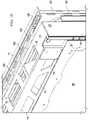
FIGURES 23 through25 illustrate acentral septum 140 which is preferably positioned substantially horizontally and near the vertical centerline of theassembly 5, although it could also be placed near the top or bottom of theassembly 5, away from the vertical centerline that extends along substantially the midline of the front surface of therear panel 60. Aright channel septum 130 extends substantially along the midline of the right side interior edge of the freestanding display housing 15 such that it is generally aligned with thecentral septum 140. Similarly, aleft channel septum 130 may be affixed on the left side interior edge of theassembly 5 such that it is aligned with thecentral septum 140.- The
central septum 140, theright channel septum 130, and the left channel septum 130 (hereinafter collectively the "horizontal partition") may be configured to substantially divide thedoor cavity 17 into an upper and lower half. The horizontal partition may be configured such that it creates a substantially air-tight seal between the upper and lower halves of thedoor cavity 17. Optionally, the horizontal partition may further comprise an expandable material, such as polyurethane foam, utilized in conjunction with the horizontal partition to provide the airtight seal between the upper and lower halves. In exemplary embodiments thecentral septum 140 may be comprised of a sufficiently flexible material, such as a polymer, to create an airtight seal in thedoor cavity 17. In alternate embodiments, thecentral septum 140 may be comprised of a rigid material. In exemplary embodiments, theright channel septum 130 and theleft channel septum 130 may be rigid. - In an exemplary embodiment, the
open loop fluid 400 may be ingested via the gap 45 (and optional rear gap 44) in the upper half of theassembly 5. Saidopen loop fluid 400a may travel along theright side channel 19 until a portion of said fluid reaches theright channel septum 130 and is prevented from traveling beyond. Similarly, theopen loop fluid 400a may travel along theleft side channel 18 until a portion of said fluid reaches the leftside channel septum 130. Said portions of the open loop fluid may be forced to return vertically in the opposite direction and circulate through the upper half ofright side channel 19 and theleft side channel 18, respectively, until eventually being ingested via theintake apertures - In a similar fashion,
open loop fluid 400b which travels along thedoor cavity 17 may travel vertically until a portion of saidfluid 400b reachescentral septum 140 and is prevented from traveling beyond. In this way, fluid 400b which has been ingested (but has not traveled through theheat exchanger 100 or the channel 102) cannot mix with the fluid 400b which has travelled through theheat exchanger 100 or thechannel 102 and needs to be exhausted out of the gap 45 (and optional rear gap 44). - As also discussed in the previous figures, the
open loop fluid 400 may circulate through theoptional heat exchanger 100 until eventually being exhausted via theexhaust apertures 85. Theopen loop fluid 400 may then eventually return to theright side channel 19 or theleft side channel 18 and travel vertically therein. Theright channel septum 130 and theleft channel septum 130, respectively, may prevent said open loop fluid from traveling beyond the midline ofassembly 5 and thereby prevent the open loop fluid from each half of theassembly 5 from becoming mixed. That is, open loop fluid not yet ingested via theintake apertures intake apertures right side septum 130 and theleft side septum 130, respectively, may be forced to return vertically in the opposite direction until eventually being exhausted from theassembly 5 via the gap 45 (and optional rear gap 44). FIGURE 26A andFIGURE 26B illustrate exemplary embodiments of thechannel septums 130. In such embodiments, a portion of thechannel septums 141 may be adjustable such that (if desired) a portion of theopen loop fluid 400a may be permitted to pass by thechannel septums 130, thereby permitting a limited amount of mixing between the ingestion and exhaustion open loop fluids. In such embodiments, a second portion of thechannel septums 142 may be static, such that they may not be adjusted and provide a substantially air-tight seal such that ingestion and exhaustion open loop fluids may not be mixed. In other embodiments, the entirety of thechannel septums 130 may be adjustable. In still other embodiments, the entirety of thechannel septums 130 may be static.- It is to be understood that scope of the disclosed embodiments provides for the cooling of many types of displays. By way of example and not by way of limitation, embodiments may be used in conjunction with any of the following electronic image assemblies: LCD (all types), light emitting diode (LED), organic light emitting diode (OLED), field emitting display (FED), light emitting polymer (LEP), organic electro luminescence (OEL), plasma displays, and any other thin panel electronic image assembly. In particular, it is contemplated that the system may be well suited for use with full color, flat panel OLED displays. Exemplary embodiments may also utilize large (55 inches or more) LED backlit, high definition liquid crystal displays (LCD). While the embodiments described herein are well suited for outdoor environments, they may also be appropriate for indoor applications (e.g., factory/industrial environments, spas, locker rooms) where thermal stability of the display may be at risk.
- As is well known in the art, electronic displays can be oriented in a portrait manner or landscape manner and either can be used with the embodiments herein.
- It should also be noted that the variety of cooling loops that are shown in the figures may be shown in a horizontal or vertical arrangement but it is clearly contemplated that this can be reversed or changed depending on the particular embodiment. Thus, the open loop may run horizontally or vertically and in a clockwise or counterclockwise direction. Further, the open loop may also be horizontal or vertical and can run left to right, right to left, and top to bottom, or bottom to top.
- Having shown and described a preferred embodiment of the invention, those skilled in the art will realize that many variations and modifications may be made to affect the described invention within the limits of the appended claims. It is the intention, therefore, to limit the invention only as indicated by the scope of the claims.
Claims (8)
- An electronic display assembly comprising:an electronic display (70);a front panel (10) positioned in front of the electronic display (70);a rear panel (60);a housing (15) for the electronic display (70);an ingestion gap (45) for ingesting open loop fluid positioned along a first vertical and a first horizontal portion of a perimeter of the front panel (10);an exhaustion gap (45) for exhausting open loop fluid positioned along a second vertical and a second horizontal portion of the perimeter of the front panel (10);a rear gap (44) configured to permit the flow of open loop fluid, in and out, positioned along a perimeter of the rear panel (60);a channel (102) positioned behind the electronic display (70);a first gaseous pathway for open loop fluid to travel from the ingestion gap (45) to the channel (102);a second gaseous pathway for open loop fluid to travel from the channel (102) to the exhaustion gap (45);a fan (81) positioned to cause the flow of the open loop fluid;a door cavity (17) defined by the space immediately behind the rear panel (60) and an interior panel (80), the interior panel (80) placed between the rear panel (60) and the electronic display (70), the door cavity (17) being configured to accept open loop fluid from the rear gap (44) and direct it towards the channel behind the electronic display (70);a buffer zone (46) positioned between the ingestion gap (45) and the exhaustion gap (45); anda central septum (140) placed within the buffer zone (46) in the door cavity (17);wherein the central septum (140) is configured to substantially divide the door cavity (17) in two halves and is configured to substantially prevent the vertical flow of open fluid.
- The electronic display assembly of claim 1 further comprising:a first side channel (21) positioned vertically and forming at least a portion of the first gaseous pathway; anda second side channel (22) positioned vertically and forming at least a portion of the second gaseous pathway.
- The electronic display assembly of claim 2 further comprising:
a channel septum (130) placed within the first side channel (21). - The electronic display assembly of claim 3wherein:
the channel septum (130) substantially prevents the vertical flow of open loop fluid. - The electronic display assembly of claim 1 wherein:
the ingestion gap (45) and the exhaustion gap (45) face an intended observer of the electronic display (70). - The electronic display assembly of claim 1 further comprising:a heat exchanger (100) having a first pathway for open loop fluid and a second pathway for circulating gas (700); anda circulating fan (32) positioned to force circulating gas (700) through the heat exchanger (100).
- The electronic display assembly of claim 1 wherein:
the channel (102) is defined by the space between an LED backlight (106) and a plate (104). - The electronic display assembly of claim 1 wherein:
the ingestion gap (45) is positioned on a first vertical half of the assembly, while the exhaustion gap (45) is positioned on the opposing vertical half of the assembly.
Applications Claiming Priority (2)
| Application Number | Priority Date | Filing Date | Title |
|---|---|---|---|
| US14/624,268US9723765B2 (en) | 2015-02-17 | 2015-02-17 | Perimeter ventilation system for electronic display |
| PCT/US2016/017973WO2016133852A1 (en) | 2015-02-17 | 2016-02-15 | Perimeter ventilation system for electronic display |
Publications (3)
| Publication Number | Publication Date |
|---|---|
| EP3259968A1 EP3259968A1 (en) | 2017-12-27 |
| EP3259968A4 EP3259968A4 (en) | 2018-10-24 |
| EP3259968B1true EP3259968B1 (en) | 2022-04-06 |
Family
ID=56622514
Family Applications (1)
| Application Number | Title | Priority Date | Filing Date |
|---|---|---|---|
| EP16752870.2AActiveEP3259968B1 (en) | 2015-02-17 | 2016-02-15 | Perimeter ventilation system for electronic display |
Country Status (8)
| Country | Link |
|---|---|
| US (3) | US9723765B2 (en) |
| EP (1) | EP3259968B1 (en) |
| JP (1) | JP6526245B2 (en) |
| KR (1) | KR102109072B1 (en) |
| CN (1) | CN107251671B (en) |
| AU (1) | AU2016220308B2 (en) |
| CA (1) | CA2976116C (en) |
| WO (1) | WO2016133852A1 (en) |
Cited By (15)
| Publication number | Priority date | Publication date | Assignee | Title |
|---|---|---|---|---|
| US11540418B2 (en) | 2008-03-03 | 2022-12-27 | Manufacturing Resources International, Inc. | Electronic display with cooling |
| US11989059B2 (en) | 2019-04-03 | 2024-05-21 | Manufacturing Resources International, Inc. | Electronic display assembly with a channel for ambient air in an access panel |
| US12004311B2 (en) | 2018-07-30 | 2024-06-04 | Manufacturing Resources International, Inc. | Housing assembly for an integrated display unit |
| US12004310B2 (en) | 2020-10-23 | 2024-06-04 | Manufacturing Resources International, Inc. | Display assemblies incorporating electric vehicle charging equipment |
| US12010824B2 (en) | 2019-02-26 | 2024-06-11 | Manufacturing Resources International, Inc. | Display assembly with loopback cooling |
| US12010813B2 (en) | 2022-07-22 | 2024-06-11 | Manufacturing Resources International, Inc. | Self-contained electronic display assembly, mounting structure and methods for the same |
| US12035486B1 (en) | 2022-07-25 | 2024-07-09 | Manufacturing Resources International, Inc. | Electronic display assembly with fabric panel communications box |
| US12052850B2 (en) | 2020-10-02 | 2024-07-30 | Manufacturing Resources International, Inc. | Field customizable airflow system for a communications box |
| US12072561B2 (en) | 2022-07-22 | 2024-08-27 | Manufacturing Resources International, Inc. | Self-contained electronic display assembly, mounting structure and methods for the same |
| US12089382B2 (en) | 2021-11-23 | 2024-09-10 | Manufacturing Resources International, Inc. | Display assembly with divided interior space |
| US12127383B2 (en) | 2007-11-16 | 2024-10-22 | Manufacturing Resources International, Inc. | Electronic display assembly with thermal management |
| US12153479B2 (en) | 2021-07-28 | 2024-11-26 | Manufacturing Resources International, Inc. | Display assemblies for providing compressive forces at electronic display layers |
| US12317461B2 (en) | 2021-08-23 | 2025-05-27 | Manufacturing Resources International, Inc. | Fan unit for providing improved airflow within display assemblies |
| US12408312B2 (en) | 2021-07-28 | 2025-09-02 | Manufacturing Resources International, Inc. | Display assemblies with vents |
| US12443067B2 (en) | 2023-07-14 | 2025-10-14 | Manufacturing Resources International, Inc. | Display assemblies inducing turbulent flow |
Families Citing this family (58)
| Publication number | Priority date | Publication date | Assignee | Title |
|---|---|---|---|---|
| US8854595B2 (en) | 2008-03-03 | 2014-10-07 | Manufacturing Resources International, Inc. | Constricted convection cooling system for an electronic display |
| US9173325B2 (en) | 2008-03-26 | 2015-10-27 | Manufacturing Resources International, Inc. | Heat exchanger for back to back electronic displays |
| US8773633B2 (en) | 2008-03-03 | 2014-07-08 | Manufacturing Resources International, Inc. | Expanded heat sink for electronic displays |
| US8497972B2 (en) | 2009-11-13 | 2013-07-30 | Manufacturing Resources International, Inc. | Thermal plate with optional cooling loop in electronic display |
| US8693185B2 (en) | 2008-03-26 | 2014-04-08 | Manufacturing Resources International, Inc. | System and method for maintaining a consistent temperature gradient across an electronic display |
| US8749749B2 (en) | 2008-12-18 | 2014-06-10 | Manufacturing Resources International, Inc. | System for cooling an electronic image assembly with manifolds and ambient gas |
| US10827656B2 (en) | 2008-12-18 | 2020-11-03 | Manufacturing Resources International, Inc. | System for cooling an electronic image assembly with circulating gas and ambient gas |
| EP2909829B1 (en) | 2012-10-16 | 2020-02-12 | Manufacturing Resources International, INC. | Back pan cooling assembly for electronic display |
| WO2014149773A1 (en) | 2013-03-15 | 2014-09-25 | Manufacturing Resources International, Inc. | Heat exchange assembly for an electronic display |
| US10524384B2 (en) | 2013-03-15 | 2019-12-31 | Manufacturing Resources International, Inc. | Cooling assembly for an electronic display |
| AU2014287438B2 (en) | 2013-07-08 | 2017-09-28 | Manufacturing Resources International, Inc. | Figure eight closed loop cooling system for electronic display |
| JP6305564B2 (en) | 2014-04-30 | 2018-04-04 | マニュファクチャリング・リソーシズ・インターナショナル・インコーポレーテッド | Back-to-back electronic display assembly |
| US9723765B2 (en) | 2015-02-17 | 2017-08-01 | Manufacturing Resources International, Inc. | Perimeter ventilation system for electronic display |
| US9857618B2 (en)* | 2015-05-18 | 2018-01-02 | Michael S. Barnes | Display enclosure with passive cooling system |
| US10820445B2 (en) | 2016-03-04 | 2020-10-27 | Manufacturing Resources International, Inc. | Cooling system for double sided display assembly |
| US10485113B2 (en) | 2017-04-27 | 2019-11-19 | Manufacturing Resources International, Inc. | Field serviceable and replaceable display |
| KR102262912B1 (en) | 2017-04-27 | 2021-06-10 | 매뉴팩처링 리소시스 인터내셔널 인코포레이티드 | A system and method for preventing warping of a display device |
| GB2565997B (en)* | 2017-04-28 | 2019-10-16 | Amscreen Group Ltd | Crossflow heat-exchangers |
| US10455225B2 (en)* | 2017-05-12 | 2019-10-22 | Pure Depth Limited | Multi-layered display with interstitial layer air filter |
| KR102020536B1 (en)* | 2017-07-31 | 2019-09-10 | 엘지전자 주식회사 | A Cooler for Display Device |
| KR102021554B1 (en)* | 2017-07-31 | 2019-11-04 | 엘지전자 주식회사 | A Cooler for Display Device |
| US10559965B2 (en) | 2017-09-21 | 2020-02-11 | Manufacturing Resources International, Inc. | Display assembly having multiple charging ports |
| CN110267503B (en)* | 2019-07-16 | 2020-12-22 | 合肥统旭智慧科技有限公司 | Outdoor high bright liquid crystal display forced air cooling system |
| CN111798758B (en)* | 2019-07-16 | 2023-03-31 | 友达光电股份有限公司 | Display device |
| US11496091B2 (en) | 2019-08-27 | 2022-11-08 | Manufacturing Resources International, Inc. | Electronic display assemblies with solar panels |
| KR102186602B1 (en)* | 2019-09-04 | 2020-12-03 | 엘지전자 주식회사 | A Cooler for Display Device |
| USD913276S1 (en) | 2019-09-25 | 2021-03-16 | Manufacturing Resources International, Inc. | Electronic display kiosk |
| USD913277S1 (en) | 2019-09-25 | 2021-03-16 | Manufacturing Resources International, Inc. | Electronic display kiosk |
| USD913278S1 (en) | 2019-09-25 | 2021-03-16 | Manufacturing Resources International, Inc. | Electronic display kiosk |
| USD916189S1 (en)* | 2019-10-08 | 2021-04-13 | Manufacturing Resources International, Inc. | Combined electronic display assembly and pole |
| USD916975S1 (en)* | 2019-10-08 | 2021-04-20 | Manufacturing Resources International, Inc. | Combined electronic display assemblies and pole |
| USD916973S1 (en)* | 2019-10-08 | 2021-04-20 | Manufacturing Resources International, Inc. | Combined electronic display assembly and pole |
| USD916976S1 (en)* | 2019-10-08 | 2021-04-20 | Manufacturing Resources International, Inc. | Combined electronic display assemblies and pole |
| USD916190S1 (en)* | 2019-10-08 | 2021-04-13 | Manufacturing Resources International, Inc. | Combined electronic display assemblies and pole |
| USD916972S1 (en)* | 2019-10-08 | 2021-04-20 | Manufacturing Resources International, Inc. | Combined electronic display assembly and pole |
| USD916977S1 (en)* | 2019-10-08 | 2021-04-20 | Manufacturing Resources International, Inc. | Combined electronic display assemblies and pole |
| USD916974S1 (en)* | 2019-10-08 | 2021-04-20 | Manufacturing Resources International, Inc. | Combined electronic display assemblies and pole |
| USD916971S1 (en)* | 2019-10-08 | 2021-04-20 | Manufacturing Resources International, Inc. | Combined electronic display assembly and pole |
| USD958059S1 (en) | 2019-10-29 | 2022-07-19 | Manufacturing Resources International, Inc. | Solar powered electronic display assembly with pole mount |
| USD957317S1 (en) | 2019-10-29 | 2022-07-12 | Manufacturing Resources International, Inc. | Solar powered electronic display kiosk |
| USD1010858S1 (en) | 2019-10-29 | 2024-01-09 | Manufacturing Resources International, Inc. | Bus shelter with solar powered electronic displays |
| USD934159S1 (en) | 2019-10-29 | 2021-10-26 | Manufacturing Resources International, Inc. | Canopy with solar powered electronic menu board |
| US11470749B2 (en) | 2020-10-23 | 2022-10-11 | Manufacturing Resources International, Inc. | Forced air cooling for display assemblies using centrifugal fans |
| USD993906S1 (en) | 2021-06-04 | 2023-08-01 | Manufacturing Resources International, Inc. | Combined solar powered electronic display assembly with charging station |
| USD964920S1 (en) | 2021-06-04 | 2022-09-27 | Manufacturing Resources International, Inc. | Solar powered electronic display assembly |
| US11762231B2 (en) | 2021-08-23 | 2023-09-19 | Manufacturing Resources International, Inc. | Display assemblies inducing turbulent flow |
| US11919393B2 (en) | 2021-08-23 | 2024-03-05 | Manufacturing Resources International, Inc. | Display assemblies inducing relatively turbulent flow and integrating electric vehicle charging equipment |
| CN114786392B (en)* | 2022-05-16 | 2024-01-26 | 深圳市润达通电子有限公司 | Prevent PCBA mainboard that breaks has heat dissipation circulation function |
| USD1029939S1 (en)* | 2022-08-31 | 2024-06-04 | Manufacturing Resources International, Inc. | Electronic display unit |
| US12039894B2 (en) | 2022-08-31 | 2024-07-16 | Manufacturing Resources International, Inc. | Display assembly with unobstructed zone |
| US11997808B2 (en) | 2022-08-31 | 2024-05-28 | Manufacturing Resources International, Inc. | Display assembly with unobstructed zone |
| US12106687B2 (en) | 2022-08-31 | 2024-10-01 | Manufacturing Resources International, Inc. | Display assembly with unobstructed zone |
| USD1030873S1 (en) | 2023-03-02 | 2024-06-11 | Manufacturing Resources International, Inc. | Electronic display unit |
| USD1029778S1 (en) | 2023-06-02 | 2024-06-04 | Manufacturing Resources International, Inc. | Electronic display assembly structure |
| USD1030691S1 (en) | 2023-06-02 | 2024-06-11 | Manufacturing Resources International, Inc. | Electronic display assembly structure |
| USD1070843S1 (en) | 2023-07-17 | 2025-04-15 | Manufacturing Resources International, Inc. | Electronic display assembly |
| USD1066280S1 (en) | 2024-09-12 | 2025-03-11 | Manufacturing Resources International, Inc. | Electronic display assembly |
| USD1076846S1 (en) | 2024-09-12 | 2025-05-27 | Manufacturing Resources International, Inc. | Electronic display assembly |
Family Cites Families (369)
| Publication number | Priority date | Publication date | Assignee | Title |
|---|---|---|---|---|
| US5432526A (en) | 1970-12-28 | 1995-07-11 | Hyatt; Gilbert P. | Liquid crystal display having conductive cooling |
| US4093355A (en) | 1977-02-04 | 1978-06-06 | General Motors Corporation | Symmetrical internal heater for liquid crystal display |
| FR2542893B1 (en) | 1983-03-18 | 1985-06-21 | Thomson Csf | COLOR VISUALIZATION SCREEN WITH SMECTIC LIQUID CRYSTAL |
| JPS6082745A (en) | 1983-10-12 | 1985-05-10 | Tokiwa Sangyo Kk | Boiler |
| US4634225A (en) | 1984-12-24 | 1987-01-06 | General Electric Co. | Transflective liquid crystal display with integral heating unit and temperature sensor |
| US4748765A (en) | 1986-07-18 | 1988-06-07 | Martin Dennis K | Livewell apparatus and method |
| US4763993A (en) | 1987-04-30 | 1988-08-16 | N-View Corporation | Liquid crystal display for projection systems |
| JPH063354B2 (en) | 1987-06-23 | 1994-01-12 | アクトロニクス株式会社 | Loop type thin tube heat pipe |
| US4952925A (en) | 1988-01-25 | 1990-08-28 | Bernd Haastert | Projectable passive liquid-crystal flat screen information centers |
| JPH0262015A (en) | 1988-08-29 | 1990-03-01 | Toshiba Corp | Transformer |
| US4952783A (en) | 1989-03-20 | 1990-08-28 | W. H. Brady Co. | Light transmitting flexible film electrical heater panels |
| JPH02307080A (en) | 1989-05-22 | 1990-12-20 | Nec Corp | Liquid-cooled bt device |
| US5029982A (en) | 1989-09-11 | 1991-07-09 | Tandy Corporation | LCD contrast adjustment system |
| JPH03153212A (en) | 1989-11-10 | 1991-07-01 | Hitachi Ltd | Liquid crystal display device |
| US5088806A (en) | 1990-01-16 | 1992-02-18 | Honeywell, Inc. | Apparatus and method for temperature compensation of liquid crystal matrix displays |
| US5247374A (en) | 1990-04-05 | 1993-09-21 | Stanley Electric Co., Ltd. | Liquid crystal display device with common heater between two cells |
| US5132666A (en) | 1990-09-17 | 1992-07-21 | Travel-Ad, Inc. | Vehicle-mounted electronic display system |
| US5282114A (en) | 1991-11-05 | 1994-01-25 | Codar Technology Inc. | Ruggedized computer assembly providing accessibility and adaptability to, and effective cooling of, electronic components |
| JP2585003Y2 (en) | 1992-06-18 | 1998-11-11 | 日本電気ホームエレクトロニクス株式会社 | Liquid crystal cooler for liquid crystal projector |
| JP2618791B2 (en) | 1992-09-07 | 1997-06-11 | 東北リコー株式会社 | Liquid crystal display cooling device |
| US5293930A (en) | 1992-09-24 | 1994-03-15 | Hewlett-Packard Company | Surface-to-air heat exchanger for electronic devices |
| US5351176A (en) | 1992-12-31 | 1994-09-27 | North Atlantic Industries, Inc. | Panel for a computer including a hinged door with integral display |
| US6902378B2 (en) | 1993-07-16 | 2005-06-07 | Helix Technology Corporation | Electronically controlled vacuum pump |
| JP2981586B2 (en) | 1993-10-15 | 1999-11-22 | ダイヤモンド電機株式会社 | heatsink |
| US7231967B2 (en) | 1994-01-31 | 2007-06-19 | Building Performance Equipment, Inc. | Ventilator system and method |
| JP3234740B2 (en) | 1994-06-09 | 2001-12-04 | キヤノン株式会社 | Image display device |
| US5983543A (en) | 1994-10-05 | 1999-11-16 | Hillstrom; David U. | Outdoor menu display device |
| JP3393937B2 (en) | 1994-10-18 | 2003-04-07 | 富士写真フイルム株式会社 | Lamp temperature control device and color thermal printer using the same |
| US5767489A (en) | 1994-12-14 | 1998-06-16 | Hewlett-Packard Company | Enhanced resolution liquid crystal microthermography method and apparatus |
| SE505272C2 (en) | 1994-12-14 | 1997-07-28 | Ericsson Telefon Ab L M | Cooling system for telecommunications equipment |
| JP3179989B2 (en) | 1995-01-13 | 2001-06-25 | 松下電工株式会社 | Display device |
| WO1996030805A1 (en) | 1995-03-30 | 1996-10-03 | Seiko Epson Corporation | Projection display |
| JP3275908B2 (en) | 1995-03-30 | 2002-04-22 | セイコーエプソン株式会社 | Projection display device |
| US5559614A (en) | 1995-05-01 | 1996-09-24 | Motorola, Inc. | Liquid crystal display with integral heater and method of fabricating same |
| JPH08305301A (en) | 1995-05-10 | 1996-11-22 | Sony Corp | Liquid crystal display device |
| JPH08339034A (en) | 1995-06-13 | 1996-12-24 | Matsushita Electric Ind Co Ltd | Liquid crystal display device for overhead projector |
| US5621614A (en) | 1995-08-24 | 1997-04-15 | Lucasey Manufacturing Company | Apparatus for mounting and enclosing an appliance |
| US5657641A (en) | 1995-09-13 | 1997-08-19 | Kooltronic, Inc. | Panel mounted cooling system |
| GB9522249D0 (en) | 1995-10-31 | 1996-01-03 | Smiths Industries Ltd | Display associates |
| JPH09223883A (en) | 1996-02-16 | 1997-08-26 | Hitachi Ltd | Electronic equipment cooling device |
| US6003015A (en) | 1996-02-28 | 1999-12-14 | Hm Electronics, Inc. | Order confirmation system and method of using same |
| JPH09246766A (en) | 1996-03-13 | 1997-09-19 | Fanuc Ltd | Enclosed electronic equipment case |
| JPH09307257A (en) | 1996-05-20 | 1997-11-28 | Fujitsu General Ltd | Video display |
| JP3739486B2 (en) | 1996-06-13 | 2006-01-25 | 富士通株式会社 | Outdoor installation cabinet |
| JPH10123964A (en) | 1996-08-30 | 1998-05-15 | Sony Corp | Liquid crystal display device |
| US5748269A (en) | 1996-11-21 | 1998-05-05 | Westinghouse Air Brake Company | Environmentally-sealed, convectively-cooled active matrix liquid crystal display (LCD) |
| KR100242834B1 (en) | 1996-12-04 | 2000-02-01 | 윤종용 | LCD monitor |
| US6219113B1 (en) | 1996-12-17 | 2001-04-17 | Matsushita Electric Industrial Co., Ltd. | Method and apparatus for driving an active matrix display panel |
| US6089751A (en) | 1996-12-30 | 2000-07-18 | Honeywell Inc. | Transparent temperature sensor for an active matrix liquid crystal display |
| EP1253605B1 (en) | 1997-02-18 | 2008-10-15 | Canon Kabushiki Kaisha | Power supply unit having transformer-mounted substrate, and recording apparatus including power supply unit |
| JPH10268309A (en) | 1997-03-21 | 1998-10-09 | Furontetsuku:Kk | Liquid crystal display device |
| KR100233431B1 (en) | 1997-04-10 | 1999-12-01 | 윤종용 | Microwave Choke Circuit Protection Device |
| US5991153A (en) | 1997-10-31 | 1999-11-23 | Lacerta Enterprises, Inc. | Heat transfer system and method for electronic displays |
| US6215655B1 (en) | 1997-10-31 | 2001-04-10 | Lacerta Enterprises, Inc. | Drive-in ordering apparatus |
| US5864465A (en) | 1997-11-04 | 1999-01-26 | Liu; Michael | Device for cooling central processing units |
| US5808418A (en) | 1997-11-07 | 1998-09-15 | Honeywell Inc. | Control mechanism for regulating the temperature and output of a fluorescent lamp |
| JPH11160727A (en) | 1997-12-01 | 1999-06-18 | Advanced Display Inc | Liquid crystal display device |
| US6211934B1 (en) | 1997-12-24 | 2001-04-03 | Honeywell Inc. | Method of and apparatuses for reducing infrared loading on display devices |
| US6504713B1 (en) | 1998-01-22 | 2003-01-07 | Iv Phoenix Group, Inc. | Ultra-rugged, high-performance computer system |
| EP1057197A4 (en) | 1998-02-19 | 2002-04-17 | Universal Avionics Sys Corp | Method for cooling a lamp backlighting module of a liquid crystal display |
| TW445386B (en) | 1998-03-16 | 2001-07-11 | Hitachi Ltd | Thin-type display |
| JPH11296094A (en) | 1998-04-10 | 1999-10-29 | Matsushita Electric Ind Co Ltd | Radiation method of plasma display |
| KR20000000118U (en) | 1998-06-02 | 2000-01-15 | 윤종용 | Heat dissipation and heating device for communication equipment enclosure |
| TW393666B (en) | 1998-06-15 | 2000-06-11 | Acer Display Tech Inc | A plasma display device having a heated airflow guiding groove |
| JP2000010501A (en)* | 1998-06-18 | 2000-01-14 | Sony Corp | Mounting structure for panel type display device |
| US6428198B1 (en) | 1998-07-07 | 2002-08-06 | Alliedsignal Inc. | Display system having a light source separate from a display device |
| US6241903B1 (en) | 1998-08-20 | 2001-06-05 | Physical Optics Corporation | Diffuser master and method of manufacture |
| US6220713B1 (en) | 1998-10-23 | 2001-04-24 | Compaq Computer Corporation | Projection lens and system |
| JP4114194B2 (en) | 1998-10-29 | 2008-07-09 | 日本精機株式会社 | Head-up display device |
| US6437978B1 (en) | 1998-12-04 | 2002-08-20 | Sony Corporation | Cooling device, cooling method, and electronic apparatus |
| US6392727B1 (en) | 1998-12-31 | 2002-05-21 | Honeywell International Inc. | Reduced reflectance polarized display |
| US6933991B2 (en) | 1999-01-22 | 2005-08-23 | White Electronic Designs Corp. | Super bright low reflectance liquid crystal display |
| US6157432A (en) | 1999-01-29 | 2000-12-05 | Hewlett-Packard Company | Heated ferroelectric liquid crystal spatial light modulator with improved contrast, improved grayscale resolution, and decreased pixel sticking when operated in a non-DC balanced mode |
| US6191839B1 (en) | 1999-05-03 | 2001-02-20 | Rockwell Collin, Inc. | Patterned thermal sensor |
| JP3571965B2 (en) | 1999-07-21 | 2004-09-29 | シャープ株式会社 | Liquid crystal display |
| FI108962B (en) | 1999-08-20 | 2002-04-30 | Nokia Corp | Cooling system for plant cabinets |
| US6701143B1 (en) | 1999-12-15 | 2004-03-02 | Vert, Inc. | Apparatus, methods, and computer programs for displaying information on mobile signs |
| US6812851B1 (en) | 1999-12-15 | 2004-11-02 | Vert, Inc. | Apparatuses for displaying information on vehicles |
| US6535266B1 (en) | 1999-12-16 | 2003-03-18 | Rockwell Collins, Inc. | Closed loop LCD heater system |
| US6411042B1 (en) | 1999-12-29 | 2002-06-25 | Honeywell International Inc. | Display cold spot temperature regulator |
| US6476883B1 (en) | 2000-05-05 | 2002-11-05 | Adaptive Micro Systems, Inc. | Enclosure system for electronic displays and method for making same |
| US6812982B2 (en) | 2000-05-12 | 2004-11-02 | Fuji Photo Film Co., Ltd. | Optical compensatory sheet producing method and apparatus, thermal treating method and apparatus, and dust removing method and apparatus |
| US20020112026A1 (en) | 2000-07-18 | 2002-08-15 | Leonid Fridman | Apparatuses, methods, and computer programs for displaying information on signs |
| US6850209B2 (en) | 2000-12-29 | 2005-02-01 | Vert, Inc. | Apparatuses, methods, and computer programs for displaying information on vehicles |
| US20020164962A1 (en) | 2000-07-18 | 2002-11-07 | Mankins Matt W. D. | Apparatuses, methods, and computer programs for displaying information on mobile units, with reporting by, and control of, such units |
| US20020065046A1 (en) | 2000-07-18 | 2002-05-30 | Vert, Inc. | Apparatuses, methods, and computer programs for showing information on a vehicle having multiple displays |
| US20020009978A1 (en) | 2000-07-18 | 2002-01-24 | Semyon Dukach | Units for displaying information on vehicles |
| JP2002158475A (en) | 2000-11-20 | 2002-05-31 | Fujitsu General Ltd | Sealed housing for flat panel display |
| JP4402280B2 (en) | 2000-11-22 | 2010-01-20 | シャープ株式会社 | Liquid crystal display |
| US20040036622A1 (en) | 2000-12-15 | 2004-02-26 | Semyon Dukach | Apparatuses, methods, and computer programs for displaying information on signs |
| JP3594900B2 (en) | 2000-12-19 | 2004-12-02 | 株式会社日立製作所 | Display integrated computer |
| JP4460784B2 (en) | 2001-01-31 | 2010-05-12 | シャープ株式会社 | Liquid crystal display |
| DK1231588T3 (en) | 2001-02-12 | 2003-12-01 | Innowert Service Ct In Ges Fue | Device for holding and cooling flat screens |
| US6825828B2 (en) | 2001-02-23 | 2004-11-30 | General Digital Corporation | Backlit LCD monitor |
| JP4708587B2 (en) | 2001-03-07 | 2011-06-22 | Nec液晶テクノロジー株式会社 | Display device |
| US6607027B2 (en) | 2001-04-05 | 2003-08-19 | Modine Manufacturing Company | Spiral fin/tube heat exchanger |
| US20020149714A1 (en) | 2001-04-16 | 2002-10-17 | Robert Anderson | Ruggedized flat panel display assembly |
| US6493440B2 (en) | 2001-04-23 | 2002-12-10 | Gilbarco Inc. | Thermal management for a thin environmentally-sealed LCD display enclosure |
| KR100793727B1 (en) | 2001-05-18 | 2008-01-10 | 삼성전자주식회사 | LCD Display |
| NL1018243C2 (en) | 2001-06-08 | 2002-12-10 | Oce Tech Bv | Printhead for an image-forming device and image-forming device provided with such a printhead. |
| US6351381B1 (en) | 2001-06-20 | 2002-02-26 | Thermal Corp. | Heat management system |
| JP3471772B2 (en) | 2001-07-26 | 2003-12-02 | Necビューテクノロジー株式会社 | projector |
| US6727468B1 (en) | 2001-08-06 | 2004-04-27 | Rockwell Collins | Flexible heating system having high transmissivity |
| JP2003076286A (en) | 2001-09-06 | 2003-03-14 | Ngk Insulators Ltd | Cooling system for display device |
| JP2003140559A (en) | 2001-11-07 | 2003-05-16 | Nitto Denko Corp | Film filter for preventing glass breakage and plasma display |
| US6813152B2 (en) | 2002-01-18 | 2004-11-02 | Apw Ltd. | Method for improving airflow in subrack mechanics by using a hybrid serial/parallel fan configuration |
| US6976330B2 (en) | 2002-04-04 | 2005-12-20 | Milliken & Milliken | Hinge assembly for sign box face |
| US20040035558A1 (en) | 2002-06-14 | 2004-02-26 | Todd John J. | Heat dissipation tower for circuit devices |
| US6643130B1 (en) | 2002-07-08 | 2003-11-04 | Demarchis John A. | Wash down filtered fan apparatus |
| US7269220B2 (en) | 2002-07-16 | 2007-09-11 | Broadcom Corporation | Adaptive motion detection and control |
| JP3620840B2 (en) | 2002-07-17 | 2005-02-16 | シャープ株式会社 | Liquid crystal display |
| US20040103570A1 (en) | 2002-07-26 | 2004-06-03 | Monarch Advertising, Inc. | Three dimensional advertising display and associated method of use |
| DE10235038A1 (en) | 2002-07-31 | 2004-02-12 | Behr Gmbh & Co. | Flat-tube heat exchanger |
| JP4125182B2 (en) | 2002-08-22 | 2008-07-30 | シャープ株式会社 | Liquid crystal display element, projection-type liquid crystal display apparatus, image shift element, and image display apparatus |
| JP3725106B2 (en) | 2002-08-30 | 2005-12-07 | 株式会社東芝 | Electronics |
| AU2003270750A1 (en) | 2002-09-20 | 2004-04-08 | Honeywell International, Inc. | High efficiency viewing screen |
| JP4083659B2 (en) | 2002-10-10 | 2008-04-30 | バルコ・ナムローゼ・フエンノートシャップ | Panel display and tiled display |
| EP1408476B1 (en) | 2002-10-10 | 2014-10-15 | Barco N.V. | Light emission display arrangements |
| US7190416B2 (en) | 2002-10-18 | 2007-03-13 | Nitto Denko Corporation | Liquid crystal display with touch panel having internal front polarizer |
| US7752858B2 (en) | 2002-11-25 | 2010-07-13 | American Power Conversion Corporation | Exhaust air removal system |
| US6891135B2 (en) | 2002-12-11 | 2005-05-10 | Denso International America, Inc. | High temperature shut-off for an LCD heater |
| US6816371B2 (en) | 2002-12-16 | 2004-11-09 | International Business Machines Corporation | Method and arrangement for enhancing the cooling capacity of portable computers |
| KR100505554B1 (en) | 2003-01-24 | 2005-08-03 | 아이큐리랩 홀딩스 리미티드 | Cooling device of hybrid-type |
| US6909486B2 (en) | 2003-02-18 | 2005-06-21 | Ran-Hong Raymond Wang | Liquid crystal display viewable under all lighting conditions |
| US7352428B2 (en) | 2003-02-21 | 2008-04-01 | Xtellus Inc. | Liquid crystal cell platform |
| US6943768B2 (en) | 2003-02-21 | 2005-09-13 | Xtellus Inc. | Thermal control system for liquid crystal cell |
| JP2004286940A (en) | 2003-03-20 | 2004-10-14 | Hitachi Ie Systems Co Ltd | Dustproof housing heat dissipation mechanism for plasma display panel display |
| US20040223299A1 (en) | 2003-05-07 | 2004-11-11 | Prosenjit Ghosh | Display cooling |
| GB2402205A (en) | 2003-05-20 | 2004-12-01 | Densitron Technologies Plc | A display system cabinet and display system including heat removal means |
| TW575200U (en) | 2003-06-13 | 2004-02-01 | Coretronic Corp | Cooling structure for projection apparatus |
| JP2005017556A (en) | 2003-06-25 | 2005-01-20 | Sanyo Electric Co Ltd | Liquid crystal display device |
| US7015470B2 (en) | 2003-07-15 | 2006-03-21 | Lear Corporation | Active night vision cooling system |
| KR20050009838A (en) | 2003-07-18 | 2005-01-26 | 현대자동차주식회사 | monitor with a touch screen improved reflection rate of light |
| US8237386B2 (en) | 2003-08-15 | 2012-08-07 | Apple Inc. | Methods and apparatuses for operating a data processing system |
| KR100522696B1 (en) | 2003-09-20 | 2005-10-19 | 삼성에스디아이 주식회사 | Filter holder and display apparatus comprising the same |
| US20050073639A1 (en) | 2003-10-06 | 2005-04-07 | Shin-Tung Pan | Heat dissipating structure of liquid crystal display |
| KR100563049B1 (en) | 2003-10-07 | 2006-03-24 | 삼성에스디아이 주식회사 | Plasma display device having heat insulation means |
| US7324176B2 (en) | 2003-10-07 | 2008-01-29 | American Panel Corporation | Flat panel display having integral heater, EMI shield, and thermal sensors |
| WO2005045250A2 (en) | 2003-10-28 | 2005-05-19 | Vst International, Inc. | Audio/video display equipment for gas pumps |
| JP2005134849A (en) | 2003-10-31 | 2005-05-26 | Nagoya Electric Works Co Ltd | Information display device |
| EP1704752A4 (en) | 2003-12-11 | 2009-09-23 | Philips Solid State Lighting | Thermal management methods and apparatus for lighting devices |
| EP1548573A1 (en) | 2003-12-23 | 2005-06-29 | Barco N.V. | Hierarchical control system for a tiled large-screen emissive display |
| US20050134526A1 (en) | 2003-12-23 | 2005-06-23 | Patrick Willem | Configurable tiled emissive display |
| FI116491B (en) | 2004-02-16 | 2005-11-30 | Inssimainos Oy | Method and apparatus for controlling the temperature of a display surface |
| JP2005265922A (en) | 2004-03-16 | 2005-09-29 | Matsushita Electric Ind Co Ltd | Plasma display device |
| US7239804B2 (en) | 2004-03-23 | 2007-07-03 | Canon Kabushiki Kaisha | Cooling device, and apparatus and method for manufacturing image display panel using cooling device |
| US7161803B1 (en) | 2004-04-12 | 2007-01-09 | Heady Gregory S | Cooling system for an electronic display |
| DE202004006552U1 (en) | 2004-04-26 | 2004-07-08 | Knürr AG | Cooling system for device and network cabinets |
| US7478492B2 (en) | 2004-05-14 | 2009-01-20 | Madonia Joseph R | Integrated flat panel display for mounting to exterior surfaces of motor vehicles |
| CN2702363Y (en) | 2004-05-21 | 2005-05-25 | 协禧电机股份有限公司 | Graphics card cooling module |
| US7167309B2 (en) | 2004-06-25 | 2007-01-23 | Northrop Grumman Corporation | Optical compensation of cover glass-air gap-display stack for high ambient lighting |
| KR101097486B1 (en) | 2004-06-28 | 2011-12-22 | 엘지디스플레이 주식회사 | back light unit of liquid crystal display device |
| KR100802725B1 (en) | 2004-06-30 | 2008-02-12 | 가부시키가이샤 히타치세이사쿠쇼 | LCD projectors and their liquid crystal panels and liquid cooling devices |
| JP4221605B2 (en) | 2004-07-12 | 2009-02-12 | ソニー株式会社 | Display panel device |
| US20060012985A1 (en) | 2004-07-15 | 2006-01-19 | Eastman Kodak Company | Flat panel lighting for enclosed space illumination |
| TW200605758A (en) | 2004-07-21 | 2006-02-01 | Metal Ind Res & Dev Ct | Closed-loop cycling type heat-dissipation apparatus |
| KR200366674Y1 (en) | 2004-07-30 | 2004-11-06 | 황정숙 | Air cleaner having a Advertising plate |
| US7233493B2 (en) | 2004-08-10 | 2007-06-19 | E. I. Du Pont De Nemours And Company | Electronic device having a temperature control system including a ductwork assembly |
| JP4706206B2 (en) | 2004-08-18 | 2011-06-22 | ソニー株式会社 | Heat dissipation device and display device |
| KR20060016469A (en) | 2004-08-18 | 2006-02-22 | 삼성전자주식회사 | Backlight unit and liquid crystal display including the same |
| US7177151B2 (en) | 2004-09-15 | 2007-02-13 | Lockheed Martin Corporation | Cooling devices and systems |
| JP2006085422A (en) | 2004-09-16 | 2006-03-30 | Internatl Business Mach Corp <Ibm> | Electronic equipment provided with a cooling device for the inside and surface of the housing |
| KR100616620B1 (en) | 2004-09-22 | 2006-08-28 | 삼성전기주식회사 | Noiseless high efficiency heat dissipation device using ion wind |
| US8122627B2 (en)* | 2004-09-23 | 2012-02-28 | Daktronics, Inc. | Ventilated washable electronic sign display enclosure |
| JP2006106272A (en) | 2004-10-04 | 2006-04-20 | Sony Corp | Display apparatus |
| WO2006038778A1 (en) | 2004-10-05 | 2006-04-13 | Samsung Electronics Co., Ltd. | Backlight unit |
| KR100638047B1 (en) | 2004-10-15 | 2006-10-23 | 엘지전자 주식회사 | Liquid crystal display with backlight unit |
| US7212403B2 (en) | 2004-10-25 | 2007-05-01 | Rocky Research | Apparatus and method for cooling electronics and computer components with managed and prioritized directional air flow heat rejection |
| TWI260966B (en) | 2004-10-28 | 2006-08-21 | Quanta Comp Inc | Heat dissipation device |
| KR101167301B1 (en) | 2004-10-30 | 2012-07-19 | 엘지디스플레이 주식회사 | Back light unit of liquid crystal display device |
| SI21941B (en) | 2004-11-03 | 2013-06-28 | Andraž Ogorevc | Public display |
| TWM267437U (en) | 2004-11-23 | 2005-06-11 | Forward Electronics Co Ltd | Modular heat dissipation device |
| JP2006152921A (en) | 2004-11-29 | 2006-06-15 | Sony Corp | Cooling blower fan and video display unit |
| JP2006163217A (en)* | 2004-12-10 | 2006-06-22 | Mitsubishi Electric Corp | Outdoor display device |
| JP2006171300A (en) | 2004-12-15 | 2006-06-29 | Sony Corp | Liquid crystal display and cooling device |
| KR20060070176A (en) | 2004-12-20 | 2006-06-23 | 삼성전자주식회사 | Cooling device and liquid crystal display including the same |
| US20080035315A1 (en) | 2004-12-23 | 2008-02-14 | Evga Corporation | Cooling system with miniature fans for circuit board devices |
| US7755893B2 (en) | 2005-03-15 | 2010-07-13 | Panasonic Corporation | Display device |
| JP4227969B2 (en) | 2005-03-17 | 2009-02-18 | Necディスプレイソリューションズ株式会社 | Projection display |
| GB0509742D0 (en) | 2005-05-13 | 2005-06-22 | Ashe Morris Ltd | Variable heat flux heat exchangers |
| US20060260790A1 (en) | 2005-05-18 | 2006-11-23 | Mark Theno | Heat exchanger core |
| KR20060120373A (en) | 2005-05-19 | 2006-11-27 | 삼성전자주식회사 | Backlight unit and LCD using the same |
| US7737360B2 (en) | 2005-05-24 | 2010-06-15 | Panduit Corp. | Enclosure apparatus, system and method |
| US7604040B2 (en) | 2005-06-15 | 2009-10-20 | Coolit Systems Inc. | Integrated liquid cooled heat sink for electronic components |
| JP2007003638A (en) | 2005-06-22 | 2007-01-11 | Funai Electric Co Ltd | Projection type video display device |
| KR100691191B1 (en) | 2005-07-15 | 2007-03-09 | 삼성전기주식회사 | Surface light source using LED and LCD backlight unit having same |
| JP4828293B2 (en) | 2005-07-19 | 2011-11-30 | 東京エレクトロン株式会社 | Water removal device and inspection device in refrigerant |
| US7431475B2 (en) | 2005-07-22 | 2008-10-07 | Sony Corporation | Radiator for light emitting unit, and backlight device |
| KR101214945B1 (en) | 2005-08-17 | 2012-12-24 | 삼성디스플레이 주식회사 | Backlight assembly and display device using the same |
| KR100666961B1 (en) | 2005-08-18 | 2007-01-10 | 주식회사 파이컴 | Back light device |
| KR101264675B1 (en) | 2005-09-01 | 2013-05-16 | 엘지디스플레이 주식회사 | Backlight unit using a test device for testing of LCD Panel |
| TW200710499A (en) | 2005-09-02 | 2007-03-16 | Jemitek Electronics Corp | Backlight unit and method for uniforming brightness thereof |
| KR200401354Y1 (en) | 2005-09-07 | 2005-11-15 | 티티엠주식회사 | Cooling Structure for Liquid Crystal Display |
| JP4483833B2 (en) | 2005-09-22 | 2010-06-16 | エプソンイメージングデバイス株式会社 | Electro-optical device, electronic apparatus, protective member, and manufacturing method of protective member |
| JP4830436B2 (en) | 2005-10-03 | 2011-12-07 | 株式会社日立製作所 | Display device |
| US8400607B2 (en) | 2005-10-11 | 2013-03-19 | Barco N.V. | Display assemblies and methods of display |
| US7591508B2 (en) | 2005-11-02 | 2009-09-22 | Chung Lung Chang | Headrest mounted entertainment system |
| KR100772247B1 (en) | 2005-11-04 | 2007-11-01 | 엘지전자 주식회사 | Chillers for Flat Panel Display Devices and Flat Panel Display Devices |
| KR100747848B1 (en) | 2005-11-04 | 2007-08-08 | 엘지전자 주식회사 | Cooling Units for Flat Panel Display Devices |
| US7463487B2 (en) | 2005-11-04 | 2008-12-09 | Lg Electronics Inc. | Cooling apparatus for flat display device |
| US20070115686A1 (en) | 2005-11-23 | 2007-05-24 | Luc Tyberghien | Lighting assembly, backlight assembly, display panel, and methods of temperature control |
| KR100764380B1 (en) | 2005-12-16 | 2007-10-08 | 삼성전기주식회사 | Slim backlight unit |
| KR20070070675A (en) | 2005-12-29 | 2007-07-04 | 노틸러스효성 주식회사 | LCD cooling module and financial automation equipment using the same |
| KR100949501B1 (en) | 2005-12-29 | 2010-03-24 | 엘지디스플레이 주식회사 | Cooling equipment and manufacturing method of liquid crystal display device using the same |
| US8490424B2 (en) | 2005-12-30 | 2013-07-23 | Hussmann Corporation | LED canopy light fixture |
| KR101248899B1 (en) | 2006-01-20 | 2013-04-01 | 엘지디스플레이 주식회사 | Liquid crystal display device module |
| JP5011758B2 (en) | 2006-03-06 | 2012-08-29 | セイコーエプソン株式会社 | projector |
| JP4788409B2 (en) | 2006-03-09 | 2011-10-05 | ソニー株式会社 | Cross current blower and electronic device |
| KR100764388B1 (en) | 2006-03-17 | 2007-10-05 | 삼성전기주식회사 | Anodized Metal Substrate Module |
| EP3722409A1 (en) | 2006-03-31 | 2020-10-14 | Illumina, Inc. | Systems and devices for sequence by synthesis analysis |
| US20070237636A1 (en) | 2006-04-07 | 2007-10-11 | Sam Hsu | Computer cooling fan with display device |
| WO2007116116A1 (en) | 2006-04-11 | 2007-10-18 | Symbicon Oy | Electronic information board |
| JP2007293105A (en) | 2006-04-26 | 2007-11-08 | Sony Corp | Image display device |
| KR100769065B1 (en) | 2006-05-18 | 2007-10-22 | 엘지전자 주식회사 | Heat Sink in Plasma Display |
| JP2007322718A (en) | 2006-05-31 | 2007-12-13 | Sanyo Electric Co Ltd | Display apparatus |
| CA2654043C (en) | 2006-06-13 | 2014-05-27 | Thureon Limited | Storage unit for electronic devices |
| JP2008010361A (en) | 2006-06-30 | 2008-01-17 | Sharp Corp | Backlight device |
| US8201977B2 (en) | 2008-10-07 | 2012-06-19 | Electraled, Inc. | LED illuminated member within a refrigerated display case |
| EP1895226A3 (en) | 2006-08-29 | 2010-10-06 | Milestone AV Technologies LLC | In-wall interface and mounting method for display mount |
| JP2008060204A (en) | 2006-08-30 | 2008-03-13 | Nec Lcd Technologies Ltd | LED backlight unit and liquid crystal display device using the same |
| US8206204B2 (en) | 2006-09-21 | 2012-06-26 | Ford Global Technologies, Llc | Control unit heat management |
| US7457113B2 (en) | 2006-10-11 | 2008-11-25 | International Business Machines Corporation | Venturi bernoulli heat extraction system for laptop computers |
| KR101315465B1 (en) | 2006-10-16 | 2013-10-04 | 삼성전자주식회사 | Cooling fan unit and display apparatus having the same |
| JP4728928B2 (en) | 2006-10-23 | 2011-07-20 | Necディスプレイソリューションズ株式会社 | Cooling device for liquid crystal type image display device, cooling method therefor, and liquid crystal projector device |
| TWI345661B (en) | 2006-10-30 | 2011-07-21 | Coretronic Corp | Backlight module |
| US20080099193A1 (en) | 2006-11-01 | 2008-05-01 | Slavek Peter Aksamit | Self-regulated cooling mechanism |
| KR101273592B1 (en) | 2007-01-08 | 2013-06-11 | 삼성전자주식회사 | Panel type display device |
| EP1951020A1 (en) | 2007-01-26 | 2008-07-30 | ISL media Singapore PTE LTD | Casing to install electric or electronic instruments |
| WO2008106185A1 (en) | 2007-03-01 | 2008-09-04 | Jack Richards | Air circulation device with graphic images display |
| JP4273357B2 (en) | 2007-03-06 | 2009-06-03 | 船井電機株式会社 | Cooling fan mounting structure for thin display device and plasma television |
| US20080236005A1 (en) | 2007-03-26 | 2008-10-02 | Igor Isayev | Menu board assembly |
| JP4516582B2 (en) | 2007-05-15 | 2010-08-04 | 株式会社日立製作所 | Liquid crystal display |
| JP4996332B2 (en) | 2007-05-17 | 2012-08-08 | 日立電線メクテック株式会社 | Heat sink and manufacturing method thereof |
| JP4826956B2 (en) | 2007-05-24 | 2011-11-30 | Necディスプレイソリューションズ株式会社 | Cooling device, electronic device equipped with cooling device, and projection display device |
| US8590602B2 (en)* | 2007-06-12 | 2013-11-26 | Asymblix, Llc | Heat exchanger for outdoor enclosures |
| US20080310116A1 (en) | 2007-06-15 | 2008-12-18 | O'connor Kurt F | Heatsink having an internal plenum |
| JP4407726B2 (en) | 2007-07-04 | 2010-02-03 | セイコーエプソン株式会社 | Projector and control method |
| JP5110510B2 (en) | 2007-08-29 | 2012-12-26 | インターナショナル・ビジネス・マシーンズ・コーポレーション | Technology for cooling equipment |
| KR101435801B1 (en) | 2007-08-30 | 2014-08-29 | 엘지전자 주식회사 | Display device |
| US20090065007A1 (en) | 2007-09-06 | 2009-03-12 | Wilkinson William R | Oxygen concentrator apparatus and method |
| KR101456975B1 (en) | 2007-09-27 | 2014-10-31 | 삼성전자 주식회사 | Cooling unit and display device having the same |
| US8758144B2 (en) | 2007-10-23 | 2014-06-24 | Igt | Separable backlighting system |
| KR101407622B1 (en) | 2007-11-09 | 2014-06-13 | 삼성디스플레이 주식회사 | Display device |
| US8208115B2 (en) | 2007-11-16 | 2012-06-26 | Manufacturing Resources International, Inc. | Fluid cooled display |
| US8711321B2 (en) | 2007-11-16 | 2014-04-29 | Manufacturing Resources International, Inc. | System for thermally controlling displays |
| US8004648B2 (en) | 2007-11-16 | 2011-08-23 | Manufacturing Resources International, Inc. | Air curtain for display |
| US8854595B2 (en) | 2008-03-03 | 2014-10-07 | Manufacturing Resources International, Inc. | Constricted convection cooling system for an electronic display |
| CA2915261C (en) | 2007-11-16 | 2018-08-21 | Manufacturing Resources International, Inc. | System and method for thermally controlling an electronic display |
| US20090126914A1 (en) | 2007-11-16 | 2009-05-21 | Manufacturing Resources International, Inc. | Isolated Gas Cooling System for Cooling Electrical Components of an Electronic Display |
| US8379182B2 (en) | 2007-11-16 | 2013-02-19 | Manufacturing Resources International, Inc. | Cooling system for outdoor electronic displays |
| US8767165B2 (en) | 2007-11-16 | 2014-07-01 | Manufacturing Resources International, Inc. | Isolated gas cooling system for an electronic display |
| WO2009065125A2 (en) | 2007-11-16 | 2009-05-22 | Manufacturing Resources International, Inc. | System and method for thermally controlling an electronic display |
| US20090126907A1 (en) | 2007-11-16 | 2009-05-21 | Manufacturing Resources International, Inc. | Isolated Gas Heating System for an Electronic Display |
| US8373841B2 (en) | 2007-11-16 | 2013-02-12 | Manufacturing Resources International, Inc. | Shared isolated gas cooling system for oppositely facing electronic displays |
| US8879042B2 (en) | 2007-11-16 | 2014-11-04 | Manufacturing Resources International, Inc. | Isolated cooling system having an insulator gap and front polarizer |
| KR101521179B1 (en) | 2007-12-07 | 2015-05-20 | 삼성전자주식회사 | Liquid crystal display |
| US7660109B2 (en) | 2007-12-17 | 2010-02-09 | International Business Machines Corporation | Apparatus and method for facilitating cooling of an electronics system |
| JP5055139B2 (en) | 2008-01-09 | 2012-10-24 | 株式会社日立製作所 | Image display device |
| US8773633B2 (en) | 2008-03-03 | 2014-07-08 | Manufacturing Resources International, Inc. | Expanded heat sink for electronic displays |
| US8351014B2 (en) | 2008-03-03 | 2013-01-08 | Manufacturing Resources International, Inc. | Heat exchanger for back to back electronic displays |
| US8654302B2 (en) | 2008-03-03 | 2014-02-18 | Manufacturing Resources International, Inc. | Heat exchanger for an electronic display |
| US8497972B2 (en) | 2009-11-13 | 2013-07-30 | Manufacturing Resources International, Inc. | Thermal plate with optional cooling loop in electronic display |
| US8274622B2 (en) | 2008-03-03 | 2012-09-25 | Manufacturing Resources International, Inc. | System for using constricted convection with closed loop plenum as the convection plate |
| US8358397B2 (en) | 2008-03-03 | 2013-01-22 | Manufacturing Resources International, Inc. | System for cooling an electronic display |
| US8823916B2 (en) | 2008-03-03 | 2014-09-02 | Manufacturing Resources International, Inc. | System for cooling an electronic image assembly with a heat exchanger having internal fans |
| US8310824B2 (en) | 2009-11-13 | 2012-11-13 | Manufacturing Resources International, Inc. | Field serviceable electronic display |
| US9173325B2 (en) | 2008-03-26 | 2015-10-27 | Manufacturing Resources International, Inc. | Heat exchanger for back to back electronic displays |
| US20090231807A1 (en)* | 2008-03-13 | 2009-09-17 | Bouissiere Michael F | Waterproof Ventilated Display Enclosure |
| EP2103751A1 (en) | 2008-03-19 | 2009-09-23 | BrainLAB AG | Built-in unit for display devices |
| CN101960363B (en) | 2008-03-25 | 2013-05-01 | 日本电气株式会社 | Liquid crystal display device |
| US8693185B2 (en) | 2008-03-26 | 2014-04-08 | Manufacturing Resources International, Inc. | System and method for maintaining a consistent temperature gradient across an electronic display |
| US8102173B2 (en) | 2008-04-17 | 2012-01-24 | Teradyne, Inc. | Thermal control system for test slot of test rack for disk drive testing system with thermoelectric device and a cooling conduit |
| GB2459480B8 (en) | 2008-04-23 | 2013-07-24 | Denso Corp | A heat exchanger, a method of making a heat exchanger and a kit of parts for making a heat exchanger |
| US8472174B2 (en) | 2008-05-07 | 2013-06-25 | Vertigo Digital Displays Inc. | Video display system |
| JP5288889B2 (en) | 2008-06-03 | 2013-09-11 | 三洋電機株式会社 | Image display device |
| US8140185B2 (en) | 2008-06-09 | 2012-03-20 | The Coca-Cola Company | Virtual vendor shelf inventory management |
| KR101564278B1 (en) | 2008-06-13 | 2015-10-30 | 삼성전자 주식회사 | Liquid Crystal Display Device |
| US8553409B2 (en) | 2008-06-27 | 2013-10-08 | Dell Products L.P. | System and method for portable information handling system parallel-wall thermal shield |
| JP4883421B2 (en) | 2008-07-15 | 2012-02-22 | 日立金属株式会社 | Snow extinguishing panel |
| US8698010B2 (en) | 2008-07-17 | 2014-04-15 | Nec Corporation | Electronic apparatus, image display apparatus and method of cooling electronic apparatus |
| JP5176750B2 (en) | 2008-07-24 | 2013-04-03 | ソニー株式会社 | Light emitting device assembly, planar light source device, and liquid crystal display device assembly |
| WO2010013307A1 (en) | 2008-07-28 | 2010-02-04 | Necディスプレイソリューションズ株式会社 | Display device |
| US8087787B2 (en) | 2008-09-11 | 2012-01-03 | Spatial Photonics, Inc. | Maximizing performance of an electronic device by maintaining constant junction temperature independent of ambient temperature |
| JP5202220B2 (en) | 2008-09-30 | 2013-06-05 | 三洋電機株式会社 | Image display device |
| JP5305816B2 (en) | 2008-09-30 | 2013-10-02 | 三洋電機株式会社 | Image display device |
| JP5241416B2 (en) | 2008-09-30 | 2013-07-17 | 三洋電機株式会社 | Image display device |
| JP2010102227A (en)* | 2008-10-27 | 2010-05-06 | Kita Denshi Corp | Outdoor both side display device |
| JP5381561B2 (en) | 2008-11-28 | 2014-01-08 | 富士電機株式会社 | Semiconductor cooling device |
| KR20110099134A (en) | 2008-12-18 | 2011-09-06 | 매뉴팩처링 리소시스 인터내셔널 인코포레이티드 | Thermal Control System for Electronic Displays |
| US8760613B2 (en) | 2008-12-18 | 2014-06-24 | Manufacturing Resources International, Inc. | Modular distributed components for LED backlight |
| US8749749B2 (en) | 2008-12-18 | 2014-06-10 | Manufacturing Resources International, Inc. | System for cooling an electronic image assembly with manifolds and ambient gas |
| US8074469B2 (en) | 2008-12-31 | 2011-12-13 | General Electric Company | Refrigerator with a convertible compartment |
| TWM361858U (en) | 2009-01-05 | 2009-07-21 | Coretronic Display Solution Corp | Flat panel display |
| US20100171889A1 (en) | 2009-01-06 | 2010-07-08 | Joseph Pantel | Weather-resistant display |
| JP5216602B2 (en) | 2009-01-08 | 2013-06-19 | 株式会社日立製作所 | Image display device |
| JP4766499B2 (en) | 2009-01-19 | 2011-09-07 | 三洋電機株式会社 | Outdoor image display device |
| EP2214462B1 (en) | 2009-01-30 | 2012-09-19 | SANYO Electric Co., Ltd. | Display apparatus and display system |
| US8700226B2 (en) | 2009-02-24 | 2014-04-15 | Manufacturing Resources International, Inc. | Method for driving a cooling fan within an electronic display |
| USD608775S1 (en) | 2009-03-23 | 2010-01-26 | Lighthouse Technologies Limited | LED information display device |
| US20120020114A1 (en) | 2009-03-25 | 2012-01-26 | Sharp Kabushiki Kaisha | Backlight structure |
| WO2010134160A1 (en) | 2009-05-19 | 2010-11-25 | トヨタ自動車株式会社 | Heat exchanger and method of manufacturing the same |
| US8365409B2 (en) | 2009-05-22 | 2013-02-05 | Toyota Jidosha Kabushiki Kaisha | Heat exchanger and method of manufacturing the same |
| GB2467808B (en) | 2009-06-03 | 2011-01-12 | Moduleco Ltd | Data centre |
| JP5405908B2 (en) | 2009-06-08 | 2014-02-05 | 株式会社Tbグループ | Display device |
| JP5121783B2 (en) | 2009-06-30 | 2013-01-16 | 株式会社日立ハイテクノロジーズ | LED light source, manufacturing method thereof, exposure apparatus using LED light source, and exposure method |
| JP5361586B2 (en) | 2009-07-16 | 2013-12-04 | 三洋電機株式会社 | Image display device |
| US20110019363A1 (en) | 2009-07-23 | 2011-01-27 | Scott Vahlsing | Field serviceable display device |
| US8300203B2 (en) | 2009-08-31 | 2012-10-30 | Sanyo Electric Co., Ltd. | Display apparatus |
| US8270163B2 (en) | 2009-08-31 | 2012-09-18 | Sanyo Electric Co., Ltd. | Display apparatus |
| US20120188481A1 (en) | 2009-09-29 | 2012-07-26 | Shenzhen New Super-Bright Lcd Display Co. Ltd. | Lcd apparatus |
| JP5415206B2 (en)* | 2009-09-30 | 2014-02-12 | 三洋電機株式会社 | Image display device |
| US8248784B2 (en)* | 2009-09-30 | 2012-08-21 | Sanyo Electric Co., Ltd. | Display apparatus |
| US8854801B2 (en) | 2009-10-16 | 2014-10-07 | Apple Inc. | Portable computer display housing |
| US9170007B2 (en) | 2009-10-19 | 2015-10-27 | Jeffrey Allen Erion | LED lighting device and system |
| US8482906B2 (en) | 2009-12-10 | 2013-07-09 | Ccs-Inc. | Harsh environment liquid crystal display (LCD) enclosure |
| US20120255704A1 (en) | 2009-12-18 | 2012-10-11 | Sanyo Electric Co., Ltd. | Image display apparatus |
| KR101712100B1 (en) | 2010-01-12 | 2017-03-03 | 삼성전자 주식회사 | Cooling system and display apparatus using the same |
| US8369083B2 (en) | 2010-02-16 | 2013-02-05 | Manufacturing Resources International, Inc. | System and method for selectively engaging cooling fans within an electronic display |
| KR102063885B1 (en) | 2010-05-04 | 2020-02-11 | 매뉴팩처링 리소시스 인터내셔널 인코포레이티드 | System for cooling an electronic image assembly |
| JP5501866B2 (en) | 2010-06-03 | 2014-05-28 | 三菱電機株式会社 | Suspended member mounting device |
| JP2012003060A (en) | 2010-06-17 | 2012-01-05 | Canon Inc | Image display device, holding member thereof, and image display system |
| US8335081B2 (en) | 2010-07-16 | 2012-12-18 | Rockwell Automation Technologies, Inc. | Heat sink cooling arrangement for multiple power electronic circuits |
| WO2012021573A2 (en) | 2010-08-12 | 2012-02-16 | Manufacturing Resources International, Inc. | Expanded heat sink for electronic displays and method of producing the same |
| JP5061225B2 (en) | 2010-08-19 | 2012-10-31 | シャープ株式会社 | Display device |
| CA2809019C (en) | 2010-08-20 | 2018-09-25 | Manufacturing Resources International, Inc. | System for thermally controlling an electronic display with reduced noise emissions |
| CN103180778A (en) | 2010-08-20 | 2013-06-26 | 制造资源国际公司 | System and method for thermally controlling an electronic display with reduced noise emissions |
| JP2012068486A (en) | 2010-09-24 | 2012-04-05 | Sony Corp | Display device, optical member, and method for manufacturing optical member |
| US9121595B2 (en) | 2010-10-18 | 2015-09-01 | Jeffrey Allen Erion | LED lighting device and system |
| JP2012133254A (en)* | 2010-12-24 | 2012-07-12 | Sanyo Electric Co Ltd | Outdoor display system |
| US8678603B2 (en) | 2011-03-29 | 2014-03-25 | Shenzhen China Star Optoelectronics Technology Co., Ltd. | Backlight module having elastic holder and liquid crystal display employing same |
| KR101791914B1 (en) | 2011-04-01 | 2017-11-01 | 삼성전자주식회사 | Display apparatus |
| KR101784342B1 (en) | 2011-04-08 | 2017-10-13 | 삼성전자주식회사 | Outdoor display apparatus |
| US8755021B2 (en) | 2011-05-04 | 2014-06-17 | Manufacturing Resources International, Inc. | System for cooling an electronic image assembly with manifolds and ambient gas |
| US20130173358A1 (en) | 2012-01-03 | 2013-07-04 | Frias Transportation Infrastructure Llc | Associating vehicles with advertisement display and conversion |
| US9153151B2 (en)* | 2012-01-27 | 2015-10-06 | Time-O-Matic, LLC. | Sign ventilation system |
| US8605434B2 (en) | 2012-05-01 | 2013-12-10 | Adlink Technology Inc. | Wall-mounting structure for wall-mounted electronic device |
| WO2013182733A1 (en) | 2012-06-08 | 2013-12-12 | Mitron Oy | Information display and a method for cooling an information display |
| GB2504936B (en) | 2012-08-13 | 2014-09-10 | Electronic Temperature Instr Ltd | A display assembly |
| US9207484B2 (en) | 2012-09-26 | 2015-12-08 | Apple Inc. | Computer LED bar and thermal architecture features |
| EP2909829B1 (en) | 2012-10-16 | 2020-02-12 | Manufacturing Resources International, INC. | Back pan cooling assembly for electronic display |
| US9348174B2 (en) | 2013-03-14 | 2016-05-24 | Manufacturing Resources International, Inc. | Rigid LCD assembly |
| US10524384B2 (en) | 2013-03-15 | 2019-12-31 | Manufacturing Resources International, Inc. | Cooling assembly for an electronic display |
| WO2014149773A1 (en)* | 2013-03-15 | 2014-09-25 | Manufacturing Resources International, Inc. | Heat exchange assembly for an electronic display |
| JP6120655B2 (en) | 2013-04-18 | 2017-04-26 | キヤノン株式会社 | Image forming apparatus |
| KR102120763B1 (en) | 2013-05-09 | 2020-06-09 | 엘지전자 주식회사 | Digital signage |
| JP2014225595A (en)* | 2013-05-17 | 2014-12-04 | パナソニック株式会社 | Cooling device and electronic apparatus equipped with the same |
| AU2014287438B2 (en) | 2013-07-08 | 2017-09-28 | Manufacturing Resources International, Inc. | Figure eight closed loop cooling system for electronic display |
| US20150253611A1 (en) | 2014-03-06 | 2015-09-10 | Litemax Electronics Inc. | Two-sided liquid crystal display |
| ES2876252T3 (en) | 2014-03-11 | 2021-11-12 | Mri Inc | Procedure for mounting a display on a wall |
| JP6305564B2 (en) | 2014-04-30 | 2018-04-04 | マニュファクチャリング・リソーシズ・インターナショナル・インコーポレーテッド | Back-to-back electronic display assembly |
| US9500896B2 (en) | 2014-06-16 | 2016-11-22 | Manufacturing Resources International, Inc. | Cooling system for liquid crystal display |
| US9282676B1 (en) | 2014-11-25 | 2016-03-08 | Manufacturing Resources International, Inc. | Suspended electronic display and cooling assembly |
| WO2016102980A1 (en) | 2014-12-24 | 2016-06-30 | Amscreen Group Limited | Large-scale electronic displays and methods of manufacturing the same |
| US9613548B2 (en) | 2015-01-06 | 2017-04-04 | Manufacturing Resources International, Inc. | Advanced cooling system for electronic display |
| CN104684363B (en) | 2015-02-13 | 2017-07-21 | 华为技术有限公司 | A kind of outdoor display screen and communication equipment |
| US9723765B2 (en) | 2015-02-17 | 2017-08-01 | Manufacturing Resources International, Inc. | Perimeter ventilation system for electronic display |
| US9451060B1 (en) | 2015-10-15 | 2016-09-20 | Civiq Smartscapes, Llc | Techniques and apparatus for controlling access to components of a personal communication structure (PCS) |
| US20170111521A1 (en) | 2015-10-15 | 2017-04-20 | Civiq Smartscapes, Llc | Techniques and apparatus for controlling access to components of a personal communication structure (pcs) |
| US9823690B2 (en) | 2015-09-11 | 2017-11-21 | Civiq Smartscapes, Llc | Techniques and apparatus for securing a structure to a support |
| US9703320B2 (en) | 2015-09-17 | 2017-07-11 | Civiq Smartscapes, Llc | Techniques and apparatus for mounting a housing on a personal communication structure (PCS) |
| US9622392B1 (en) | 2015-09-17 | 2017-04-11 | Civiq Smartscapes, Llc | Techniques and apparatus for controlling the temperature of a personal communication structure (PCS) |
| US10270918B2 (en) | 2015-10-15 | 2019-04-23 | Civiq Smartscapes, Llc | Method and apparatus for power and temperature control of compartments within a personal communication structure (PCS) |
| US9516485B1 (en) | 2015-11-13 | 2016-12-06 | Civiq Smartscapes, Llc | Systems and methods for making emergency phone calls |
| WO2017087496A1 (en) | 2015-11-16 | 2017-05-26 | Civiq Smartscapes, Llc | Systems and techniques for vandalism detection in a personal communication structure (pcs) |
| US20170163519A1 (en) | 2015-11-16 | 2017-06-08 | Civiq Smartscapes, Llc | Techniques and systems for servicing a personal communication structure (pcs) |
| US20170140344A1 (en) | 2015-11-16 | 2017-05-18 | Civiq Smartscapes, Llc | Systems and methods for field replacement of serviceable units |
| US10820445B2 (en) | 2016-03-04 | 2020-10-27 | Manufacturing Resources International, Inc. | Cooling system for double sided display assembly |
| US10485113B2 (en) | 2017-04-27 | 2019-11-19 | Manufacturing Resources International, Inc. | Field serviceable and replaceable display |
| KR102262912B1 (en) | 2017-04-27 | 2021-06-10 | 매뉴팩처링 리소시스 인터내셔널 인코포레이티드 | A system and method for preventing warping of a display device |
- 2015
- 2015-02-17USUS14/624,268patent/US9723765B2/enactiveActive
- 2016
- 2016-02-15CNCN201680010005.XApatent/CN107251671B/ennot_activeExpired - Fee Related
- 2016-02-15WOPCT/US2016/017973patent/WO2016133852A1/ennot_activeCeased
- 2016-02-15AUAU2016220308Apatent/AU2016220308B2/enactiveActive
- 2016-02-15JPJP2017560902Apatent/JP6526245B2/ennot_activeExpired - Fee Related
- 2016-02-15EPEP16752870.2Apatent/EP3259968B1/enactiveActive
- 2016-02-15CACA2976116Apatent/CA2976116C/enactiveActive
- 2016-02-15KRKR1020177026230Apatent/KR102109072B1/ennot_activeExpired - Fee Related
- 2017
- 2017-07-28USUS15/662,399patent/US10278311B2/enactiveActive
- 2019
- 2019-03-01USUS16/290,197patent/US10548247B2/enactiveActive
Non-Patent Citations (1)
| Title |
|---|
| None* |
Cited By (32)
| Publication number | Priority date | Publication date | Assignee | Title |
|---|---|---|---|---|
| US12207452B2 (en) | 2007-11-16 | 2025-01-21 | Manufacturing Resources International, Inc. | Electronic display assembly with thermal management |
| US12207453B1 (en) | 2007-11-16 | 2025-01-21 | Manufacturing Resources International, Inc. | Electronic display assembly with thermal management |
| US12185512B2 (en) | 2007-11-16 | 2024-12-31 | Manufacturing Resources International, Inc. | Electronic display assembly with thermal management |
| US12127383B2 (en) | 2007-11-16 | 2024-10-22 | Manufacturing Resources International, Inc. | Electronic display assembly with thermal management |
| US12207437B2 (en) | 2008-03-03 | 2025-01-21 | Manufacturing Resources International, Inc. | Electronic display with cooling |
| US12207438B2 (en) | 2008-03-03 | 2025-01-21 | Manufacturing Resources International, Inc. | Electronic display with cooling |
| US12274022B2 (en) | 2008-03-03 | 2025-04-08 | Manufacturing Resources International, Inc. | Electronic display with cooling |
| US11540418B2 (en) | 2008-03-03 | 2022-12-27 | Manufacturing Resources International, Inc. | Electronic display with cooling |
| US12108562B2 (en) | 2008-03-03 | 2024-10-01 | Manufacturing Resources International, Inc. | Electronic display with cooling |
| US12004311B2 (en) | 2018-07-30 | 2024-06-04 | Manufacturing Resources International, Inc. | Housing assembly for an integrated display unit |
| US12096607B1 (en) | 2019-02-26 | 2024-09-17 | Manufacturing Resources International, Inc. | Display assembly with loopback cooling |
| US12010824B2 (en) | 2019-02-26 | 2024-06-11 | Manufacturing Resources International, Inc. | Display assembly with loopback cooling |
| US12271229B2 (en) | 2019-04-03 | 2025-04-08 | Manufacturing Resources International, Inc. | Electronic display assembly with a channel for ambient air in an access panel |
| US11989059B2 (en) | 2019-04-03 | 2024-05-21 | Manufacturing Resources International, Inc. | Electronic display assembly with a channel for ambient air in an access panel |
| US12052850B2 (en) | 2020-10-02 | 2024-07-30 | Manufacturing Resources International, Inc. | Field customizable airflow system for a communications box |
| US12200877B2 (en) | 2020-10-23 | 2025-01-14 | Manufacturing Resources International, Inc. | Display assemblies incorporating electric vehicle charging equipment |
| US12004310B2 (en) | 2020-10-23 | 2024-06-04 | Manufacturing Resources International, Inc. | Display assemblies incorporating electric vehicle charging equipment |
| US12153479B2 (en) | 2021-07-28 | 2024-11-26 | Manufacturing Resources International, Inc. | Display assemblies for providing compressive forces at electronic display layers |
| US12314093B2 (en) | 2021-07-28 | 2025-05-27 | Manufacturing Resources International, Inc. | Display assemblies for providing compressive forces at electronic display layers |
| US12408312B2 (en) | 2021-07-28 | 2025-09-02 | Manufacturing Resources International, Inc. | Display assemblies with vents |
| US12317461B2 (en) | 2021-08-23 | 2025-05-27 | Manufacturing Resources International, Inc. | Fan unit for providing improved airflow within display assemblies |
| US12089382B2 (en) | 2021-11-23 | 2024-09-10 | Manufacturing Resources International, Inc. | Display assembly with divided interior space |
| US12185513B2 (en) | 2021-11-23 | 2024-12-31 | Manufacturing Resources International, Inc. | Display assembly with divided interior space |
| US12072561B2 (en) | 2022-07-22 | 2024-08-27 | Manufacturing Resources International, Inc. | Self-contained electronic display assembly, mounting structure and methods for the same |
| US12222592B2 (en) | 2022-07-22 | 2025-02-11 | Manufacturing Resources International, Inc. | Self-contained electronic display assembly, mounting structure and methods for the same |
| US12197058B2 (en) | 2022-07-22 | 2025-01-14 | Manufacturing Resources International, Inc. | Self-contained electronic display assembly, mounting structure and methods for the same |
| US12193187B2 (en) | 2022-07-22 | 2025-01-07 | Manufacturing Resources International, Inc. | Self-contained electronic display assembly, mounting structure and methods for the same |
| US12393069B2 (en) | 2022-07-22 | 2025-08-19 | Manufacturing Resources International, Inc. | Self-contained electronic display assembly, mounting structure and methods for the same |
| US12010813B2 (en) | 2022-07-22 | 2024-06-11 | Manufacturing Resources International, Inc. | Self-contained electronic display assembly, mounting structure and methods for the same |
| US12108546B1 (en) | 2022-07-25 | 2024-10-01 | Manufacturing Resources International, Inc. | Electronic display assembly with fabric panel communications box |
| US12035486B1 (en) | 2022-07-25 | 2024-07-09 | Manufacturing Resources International, Inc. | Electronic display assembly with fabric panel communications box |
| US12443067B2 (en) | 2023-07-14 | 2025-10-14 | Manufacturing Resources International, Inc. | Display assemblies inducing turbulent flow |
Also Published As
| Publication number | Publication date |
|---|---|
| US10548247B2 (en) | 2020-01-28 |
| US9723765B2 (en) | 2017-08-01 |
| US10278311B2 (en) | 2019-04-30 |
| KR20170118832A (en) | 2017-10-25 |
| US20160242329A1 (en) | 2016-08-18 |
| US20190208674A1 (en) | 2019-07-04 |
| AU2016220308A1 (en) | 2017-08-31 |
| EP3259968A4 (en) | 2018-10-24 |
| AU2016220308B2 (en) | 2018-12-06 |
| EP3259968A1 (en) | 2017-12-27 |
| CN107251671B (en) | 2019-08-02 |
| US20170332523A1 (en) | 2017-11-16 |
| JP6526245B2 (en) | 2019-06-05 |
| CA2976116C (en) | 2020-11-17 |
| KR102109072B1 (en) | 2020-05-11 |
| JP2018511838A (en) | 2018-04-26 |
| CA2976116A1 (en) | 2016-08-25 |
| CN107251671A (en) | 2017-10-13 |
| WO2016133852A1 (en) | 2016-08-25 |
Similar Documents
| Publication | Publication Date | Title |
|---|---|---|
| US10548247B2 (en) | Perimeter ventilation system | |
| US9613548B2 (en) | Advanced cooling system for electronic display | |
| US9451733B2 (en) | System for thermally controlling an electronic display with reduced noise emissions | |
| US10524384B2 (en) | Cooling assembly for an electronic display | |
| US10314212B2 (en) | System for cooling an electronic image assembly with circulating gas and ambient gas | |
| US8755021B2 (en) | System for cooling an electronic image assembly with manifolds and ambient gas | |
| EP2567283B1 (en) | System for cooling an electronic image assembly | |
| CA2809019C (en) | System for thermally controlling an electronic display with reduced noise emissions | |
| US8369083B2 (en) | System and method for selectively engaging cooling fans within an electronic display | |
| US20140369003A1 (en) | System for cooling an electronic image assembly with a heat exchanger having internal fans |
Legal Events
| Date | Code | Title | Description |
|---|---|---|---|
| STAA | Information on the status of an ep patent application or granted ep patent | Free format text:STATUS: THE INTERNATIONAL PUBLICATION HAS BEEN MADE | |
| PUAI | Public reference made under article 153(3) epc to a published international application that has entered the european phase | Free format text:ORIGINAL CODE: 0009012 | |
| STAA | Information on the status of an ep patent application or granted ep patent | Free format text:STATUS: REQUEST FOR EXAMINATION WAS MADE | |
| 17P | Request for examination filed | Effective date:20170816 | |
| AK | Designated contracting states | Kind code of ref document:A1 Designated state(s):AL AT BE BG CH CY CZ DE DK EE ES FI FR GB GR HR HU IE IS IT LI LT LU LV MC MK MT NL NO PL PT RO RS SE SI SK SM TR | |
| AX | Request for extension of the european patent | Extension state:BA ME | |
| DAV | Request for validation of the european patent (deleted) | ||
| DAX | Request for extension of the european patent (deleted) | ||
| A4 | Supplementary search report drawn up and despatched | Effective date:20180920 | |
| RIC1 | Information provided on ipc code assigned before grant | Ipc:F21V 29/60 20150101ALI20180915BHEP Ipc:H05K 7/20 20060101AFI20180915BHEP Ipc:G02F 1/1335 20060101ALI20180915BHEP | |
| STAA | Information on the status of an ep patent application or granted ep patent | Free format text:STATUS: EXAMINATION IS IN PROGRESS | |
| 17Q | First examination report despatched | Effective date:20201020 | |
| GRAP | Despatch of communication of intention to grant a patent | Free format text:ORIGINAL CODE: EPIDOSNIGR1 | |
| STAA | Information on the status of an ep patent application or granted ep patent | Free format text:STATUS: GRANT OF PATENT IS INTENDED | |
| INTG | Intention to grant announced | Effective date:20210420 | |
| GRAJ | Information related to disapproval of communication of intention to grant by the applicant or resumption of examination proceedings by the epo deleted | Free format text:ORIGINAL CODE: EPIDOSDIGR1 | |
| STAA | Information on the status of an ep patent application or granted ep patent | Free format text:STATUS: EXAMINATION IS IN PROGRESS | |
| INTC | Intention to grant announced (deleted) | ||
| GRAP | Despatch of communication of intention to grant a patent | Free format text:ORIGINAL CODE: EPIDOSNIGR1 | |
| STAA | Information on the status of an ep patent application or granted ep patent | Free format text:STATUS: GRANT OF PATENT IS INTENDED | |
| INTG | Intention to grant announced | Effective date:20210924 | |
| GRAS | Grant fee paid | Free format text:ORIGINAL CODE: EPIDOSNIGR3 | |
| GRAA | (expected) grant | Free format text:ORIGINAL CODE: 0009210 | |
| STAA | Information on the status of an ep patent application or granted ep patent | Free format text:STATUS: THE PATENT HAS BEEN GRANTED | |
| AK | Designated contracting states | Kind code of ref document:B1 Designated state(s):AL AT BE BG CH CY CZ DE DK EE ES FI FR GB GR HR HU IE IS IT LI LT LU LV MC MK MT NL NO PL PT RO RS SE SI SK SM TR | |
| REG | Reference to a national code | Ref country code:GB Ref legal event code:FG4D | |
| REG | Reference to a national code | Ref country code:CH Ref legal event code:EP | |
| REG | Reference to a national code | Ref country code:AT Ref legal event code:REF Ref document number:1482654 Country of ref document:AT Kind code of ref document:T Effective date:20220415 | |
| REG | Reference to a national code | Ref country code:IE Ref legal event code:FG4D | |
| REG | Reference to a national code | Ref country code:DE Ref legal event code:R096 Ref document number:602016070792 Country of ref document:DE | |
| REG | Reference to a national code | Ref country code:LT Ref legal event code:MG9D | |
| REG | Reference to a national code | Ref country code:NL Ref legal event code:MP Effective date:20220406 | |
| REG | Reference to a national code | Ref country code:AT Ref legal event code:MK05 Ref document number:1482654 Country of ref document:AT Kind code of ref document:T Effective date:20220406 | |
| PG25 | Lapsed in a contracting state [announced via postgrant information from national office to epo] | Ref country code:NL Free format text:LAPSE BECAUSE OF FAILURE TO SUBMIT A TRANSLATION OF THE DESCRIPTION OR TO PAY THE FEE WITHIN THE PRESCRIBED TIME-LIMIT Effective date:20220406 | |
| PG25 | Lapsed in a contracting state [announced via postgrant information from national office to epo] | Ref country code:SE Free format text:LAPSE BECAUSE OF FAILURE TO SUBMIT A TRANSLATION OF THE DESCRIPTION OR TO PAY THE FEE WITHIN THE PRESCRIBED TIME-LIMIT Effective date:20220406 Ref country code:PT Free format text:LAPSE BECAUSE OF FAILURE TO SUBMIT A TRANSLATION OF THE DESCRIPTION OR TO PAY THE FEE WITHIN THE PRESCRIBED TIME-LIMIT Effective date:20220808 Ref country code:NO Free format text:LAPSE BECAUSE OF FAILURE TO SUBMIT A TRANSLATION OF THE DESCRIPTION OR TO PAY THE FEE WITHIN THE PRESCRIBED TIME-LIMIT Effective date:20220706 Ref country code:LT Free format text:LAPSE BECAUSE OF FAILURE TO SUBMIT A TRANSLATION OF THE DESCRIPTION OR TO PAY THE FEE WITHIN THE PRESCRIBED TIME-LIMIT Effective date:20220406 Ref country code:HR Free format text:LAPSE BECAUSE OF FAILURE TO SUBMIT A TRANSLATION OF THE DESCRIPTION OR TO PAY THE FEE WITHIN THE PRESCRIBED TIME-LIMIT Effective date:20220406 Ref country code:GR Free format text:LAPSE BECAUSE OF FAILURE TO SUBMIT A TRANSLATION OF THE DESCRIPTION OR TO PAY THE FEE WITHIN THE PRESCRIBED TIME-LIMIT Effective date:20220707 Ref country code:FI Free format text:LAPSE BECAUSE OF FAILURE TO SUBMIT A TRANSLATION OF THE DESCRIPTION OR TO PAY THE FEE WITHIN THE PRESCRIBED TIME-LIMIT Effective date:20220406 Ref country code:ES Free format text:LAPSE BECAUSE OF FAILURE TO SUBMIT A TRANSLATION OF THE DESCRIPTION OR TO PAY THE FEE WITHIN THE PRESCRIBED TIME-LIMIT Effective date:20220406 Ref country code:BG Free format text:LAPSE BECAUSE OF FAILURE TO SUBMIT A TRANSLATION OF THE DESCRIPTION OR TO PAY THE FEE WITHIN THE PRESCRIBED TIME-LIMIT Effective date:20220706 Ref country code:AT Free format text:LAPSE BECAUSE OF FAILURE TO SUBMIT A TRANSLATION OF THE DESCRIPTION OR TO PAY THE FEE WITHIN THE PRESCRIBED TIME-LIMIT Effective date:20220406 | |
| PG25 | Lapsed in a contracting state [announced via postgrant information from national office to epo] | Ref country code:RS Free format text:LAPSE BECAUSE OF FAILURE TO SUBMIT A TRANSLATION OF THE DESCRIPTION OR TO PAY THE FEE WITHIN THE PRESCRIBED TIME-LIMIT Effective date:20220406 Ref country code:PL Free format text:LAPSE BECAUSE OF FAILURE TO SUBMIT A TRANSLATION OF THE DESCRIPTION OR TO PAY THE FEE WITHIN THE PRESCRIBED TIME-LIMIT Effective date:20220406 Ref country code:LV Free format text:LAPSE BECAUSE OF FAILURE TO SUBMIT A TRANSLATION OF THE DESCRIPTION OR TO PAY THE FEE WITHIN THE PRESCRIBED TIME-LIMIT Effective date:20220406 Ref country code:IS Free format text:LAPSE BECAUSE OF FAILURE TO SUBMIT A TRANSLATION OF THE DESCRIPTION OR TO PAY THE FEE WITHIN THE PRESCRIBED TIME-LIMIT Effective date:20220806 | |
| REG | Reference to a national code | Ref country code:DE Ref legal event code:R097 Ref document number:602016070792 Country of ref document:DE | |
| PG25 | Lapsed in a contracting state [announced via postgrant information from national office to epo] | Ref country code:SM Free format text:LAPSE BECAUSE OF FAILURE TO SUBMIT A TRANSLATION OF THE DESCRIPTION OR TO PAY THE FEE WITHIN THE PRESCRIBED TIME-LIMIT Effective date:20220406 Ref country code:SK Free format text:LAPSE BECAUSE OF FAILURE TO SUBMIT A TRANSLATION OF THE DESCRIPTION OR TO PAY THE FEE WITHIN THE PRESCRIBED TIME-LIMIT Effective date:20220406 Ref country code:RO Free format text:LAPSE BECAUSE OF FAILURE TO SUBMIT A TRANSLATION OF THE DESCRIPTION OR TO PAY THE FEE WITHIN THE PRESCRIBED TIME-LIMIT Effective date:20220406 Ref country code:EE Free format text:LAPSE BECAUSE OF FAILURE TO SUBMIT A TRANSLATION OF THE DESCRIPTION OR TO PAY THE FEE WITHIN THE PRESCRIBED TIME-LIMIT Effective date:20220406 Ref country code:DK Free format text:LAPSE BECAUSE OF FAILURE TO SUBMIT A TRANSLATION OF THE DESCRIPTION OR TO PAY THE FEE WITHIN THE PRESCRIBED TIME-LIMIT Effective date:20220406 Ref country code:CZ Free format text:LAPSE BECAUSE OF FAILURE TO SUBMIT A TRANSLATION OF THE DESCRIPTION OR TO PAY THE FEE WITHIN THE PRESCRIBED TIME-LIMIT Effective date:20220406 | |
| PLBE | No opposition filed within time limit | Free format text:ORIGINAL CODE: 0009261 | |
| STAA | Information on the status of an ep patent application or granted ep patent | Free format text:STATUS: NO OPPOSITION FILED WITHIN TIME LIMIT | |
| 26N | No opposition filed | Effective date:20230110 | |
| PG25 | Lapsed in a contracting state [announced via postgrant information from national office to epo] | Ref country code:AL Free format text:LAPSE BECAUSE OF FAILURE TO SUBMIT A TRANSLATION OF THE DESCRIPTION OR TO PAY THE FEE WITHIN THE PRESCRIBED TIME-LIMIT Effective date:20220406 | |
| PG25 | Lapsed in a contracting state [announced via postgrant information from national office to epo] | Ref country code:SI Free format text:LAPSE BECAUSE OF FAILURE TO SUBMIT A TRANSLATION OF THE DESCRIPTION OR TO PAY THE FEE WITHIN THE PRESCRIBED TIME-LIMIT Effective date:20220406 | |
| P01 | Opt-out of the competence of the unified patent court (upc) registered | Effective date:20230511 | |
| PG25 | Lapsed in a contracting state [announced via postgrant information from national office to epo] | Ref country code:MC Free format text:LAPSE BECAUSE OF FAILURE TO SUBMIT A TRANSLATION OF THE DESCRIPTION OR TO PAY THE FEE WITHIN THE PRESCRIBED TIME-LIMIT Effective date:20220406 | |
| REG | Reference to a national code | Ref country code:CH Ref legal event code:PL | |
| REG | Reference to a national code | Ref country code:BE Ref legal event code:MM Effective date:20230228 | |
| PG25 | Lapsed in a contracting state [announced via postgrant information from national office to epo] | Ref country code:LU Free format text:LAPSE BECAUSE OF NON-PAYMENT OF DUE FEES Effective date:20230215 Ref country code:LI Free format text:LAPSE BECAUSE OF NON-PAYMENT OF DUE FEES Effective date:20230228 Ref country code:CH Free format text:LAPSE BECAUSE OF NON-PAYMENT OF DUE FEES Effective date:20230228 | |
| REG | Reference to a national code | Ref country code:IE Ref legal event code:MM4A | |
| PG25 | Lapsed in a contracting state [announced via postgrant information from national office to epo] | Ref country code:IE Free format text:LAPSE BECAUSE OF NON-PAYMENT OF DUE FEES Effective date:20230215 | |
| PG25 | Lapsed in a contracting state [announced via postgrant information from national office to epo] | Ref country code:BE Free format text:LAPSE BECAUSE OF NON-PAYMENT OF DUE FEES Effective date:20230228 | |
| PG25 | Lapsed in a contracting state [announced via postgrant information from national office to epo] | Ref country code:BG Free format text:LAPSE BECAUSE OF FAILURE TO SUBMIT A TRANSLATION OF THE DESCRIPTION OR TO PAY THE FEE WITHIN THE PRESCRIBED TIME-LIMIT Effective date:20220406 | |
| PG25 | Lapsed in a contracting state [announced via postgrant information from national office to epo] | Ref country code:BG Free format text:LAPSE BECAUSE OF FAILURE TO SUBMIT A TRANSLATION OF THE DESCRIPTION OR TO PAY THE FEE WITHIN THE PRESCRIBED TIME-LIMIT Effective date:20220406 | |
| PGFP | Annual fee paid to national office [announced via postgrant information from national office to epo] | Ref country code:GB Payment date:20241205 Year of fee payment:10 | |
| PGFP | Annual fee paid to national office [announced via postgrant information from national office to epo] | Ref country code:DE Payment date:20250218 Year of fee payment:10 | |
| PGFP | Annual fee paid to national office [announced via postgrant information from national office to epo] | Ref country code:FR Payment date:20250219 Year of fee payment:10 | |
| PGFP | Annual fee paid to national office [announced via postgrant information from national office to epo] | Ref country code:IT Payment date:20250228 Year of fee payment:10 | |
| PG25 | Lapsed in a contracting state [announced via postgrant information from national office to epo] | Ref country code:CY Free format text:LAPSE BECAUSE OF FAILURE TO SUBMIT A TRANSLATION OF THE DESCRIPTION OR TO PAY THE FEE WITHIN THE PRESCRIBED TIME-LIMIT; INVALID AB INITIO Effective date:20160215 | |
| PG25 | Lapsed in a contracting state [announced via postgrant information from national office to epo] | Ref country code:HU Free format text:LAPSE BECAUSE OF FAILURE TO SUBMIT A TRANSLATION OF THE DESCRIPTION OR TO PAY THE FEE WITHIN THE PRESCRIBED TIME-LIMIT; INVALID AB INITIO Effective date:20160215 |