EP3259199B1 - Multi chamber delivery system - Google Patents
Multi chamber delivery systemDownload PDFInfo
- Publication number
- EP3259199B1 EP3259199B1EP15710703.8AEP15710703AEP3259199B1EP 3259199 B1EP3259199 B1EP 3259199B1EP 15710703 AEP15710703 AEP 15710703AEP 3259199 B1EP3259199 B1EP 3259199B1
- Authority
- EP
- European Patent Office
- Prior art keywords
- storage chambers
- oral care
- care product
- mixing chamber
- dispenser
- Prior art date
- Legal status (The legal status is an assumption and is not a legal conclusion. Google has not performed a legal analysis and makes no representation as to the accuracy of the status listed.)
- Active
Links
- 238000003860storageMethods0.000claimsdescription110
- 239000000463materialSubstances0.000claimsdescription5
- 239000012530fluidSubstances0.000claimsdescription2
- 239000000203mixtureSubstances0.000description22
- 238000009472formulationMethods0.000description16
- 239000000126substanceSubstances0.000description11
- 230000009977dual effectEffects0.000description7
- 230000002087whitening effectEffects0.000description6
- MHAJPDPJQMAIIY-UHFFFAOYSA-NHydrogen peroxideChemical compoundOOMHAJPDPJQMAIIY-UHFFFAOYSA-N0.000description4
- 239000004698PolyethyleneSubstances0.000description4
- 230000008901benefitEffects0.000description4
- 239000007788liquidSubstances0.000description4
- 229920000573polyethylenePolymers0.000description4
- -1conditionersSubstances0.000description3
- 239000004615ingredientSubstances0.000description3
- 108090000790EnzymesProteins0.000description2
- 102000004190EnzymesHuman genes0.000description2
- 229920000219Ethylene vinyl alcoholPolymers0.000description2
- 239000001045blue dyeSubstances0.000description2
- 239000000551dentifriceSubstances0.000description2
- 239000003814drugSubstances0.000description2
- 229940079593drugDrugs0.000description2
- 229940088598enzymeDrugs0.000description2
- 239000011888foilSubstances0.000description2
- 239000000499gelSubstances0.000description2
- 239000008240homogeneous mixtureSubstances0.000description2
- 229920001684low density polyethylenePolymers0.000description2
- 239000004702low-density polyethyleneSubstances0.000description2
- 238000004519manufacturing processMethods0.000description2
- 230000007246mechanismEffects0.000description2
- 230000009467reductionEffects0.000description2
- 239000002356single layerSubstances0.000description2
- 239000007787solidSubstances0.000description2
- 239000012780transparent materialSubstances0.000description2
- 229920001824Barex®Polymers0.000description1
- WQZGKKKJIJFFOK-GASJEMHNSA-NGlucoseNatural productsOC[C@H]1OC(O)[C@H](O)[C@@H](O)[C@@H]1OWQZGKKKJIJFFOK-GASJEMHNSA-N0.000description1
- 108010015776Glucose oxidaseProteins0.000description1
- 239000004366Glucose oxidaseSubstances0.000description1
- 239000004677NylonSubstances0.000description1
- 206010035148PlagueDiseases0.000description1
- 241000607479Yersinia pestisSpecies0.000description1
- 239000000853adhesiveSubstances0.000description1
- 230000001070adhesive effectEffects0.000description1
- 229910052782aluminiumInorganic materials0.000description1
- XAGFODPZIPBFFR-UHFFFAOYSA-NaluminiumChemical compound[Al]XAGFODPZIPBFFR-UHFFFAOYSA-N0.000description1
- 230000004888barrier functionEffects0.000description1
- WQZGKKKJIJFFOK-VFUOTHLCSA-Nbeta-D-glucoseChemical compoundOC[C@H]1O[C@@H](O)[C@H](O)[C@@H](O)[C@@H]1OWQZGKKKJIJFFOK-VFUOTHLCSA-N0.000description1
- 239000011127biaxially oriented polypropyleneSubstances0.000description1
- 239000003054catalystSubstances0.000description1
- 239000003086colorantSubstances0.000description1
- 238000004040coloringMethods0.000description1
- 239000006103coloring componentSubstances0.000description1
- 230000001010compromised effectEffects0.000description1
- 239000002537cosmeticSubstances0.000description1
- 239000005548dental materialSubstances0.000description1
- 230000001419dependent effectEffects0.000description1
- 239000004715ethylene vinyl alcoholSubstances0.000description1
- 238000001125extrusionMethods0.000description1
- 239000008103glucoseSubstances0.000description1
- 229940116332glucose oxidaseDrugs0.000description1
- 235000019420glucose oxidaseNutrition0.000description1
- 239000006210lotionSubstances0.000description1
- 239000000314lubricantSubstances0.000description1
- 238000002483medicationMethods0.000description1
- 229910052751metalInorganic materials0.000description1
- 239000002184metalSubstances0.000description1
- 229920001778nylonPolymers0.000description1
- 230000037361pathwayEffects0.000description1
- 229920003023plasticPolymers0.000description1
- 239000004033plasticSubstances0.000description1
- 229920006350polyacrylonitrile resinPolymers0.000description1
- 229920006254polymer filmPolymers0.000description1
- 229920005990polystyrene resinPolymers0.000description1
- 239000000843powderSubstances0.000description1
- 230000004044responseEffects0.000description1
- 230000035945sensitivityEffects0.000description1
- 239000002453shampooSubstances0.000description1
- 239000000344soapSubstances0.000description1
- 239000000758substrateSubstances0.000description1
- KKEYFWRCBNTPAC-UHFFFAOYSA-Lterephthalate(2-)Chemical compound[O-]C(=O)C1=CC=C(C([O-])=O)C=C1KKEYFWRCBNTPAC-UHFFFAOYSA-L0.000description1
- 230000000007visual effectEffects0.000description1
- 238000003466weldingMethods0.000description1
Images


Classifications
- B—PERFORMING OPERATIONS; TRANSPORTING
- B65—CONVEYING; PACKING; STORING; HANDLING THIN OR FILAMENTARY MATERIAL
- B65D—CONTAINERS FOR STORAGE OR TRANSPORT OF ARTICLES OR MATERIALS, e.g. BAGS, BARRELS, BOTTLES, BOXES, CANS, CARTONS, CRATES, DRUMS, JARS, TANKS, HOPPERS, FORWARDING CONTAINERS; ACCESSORIES, CLOSURES, OR FITTINGS THEREFOR; PACKAGING ELEMENTS; PACKAGES
- B65D81/00—Containers, packaging elements, or packages, for contents presenting particular transport or storage problems, or adapted to be used for non-packaging purposes after removal of contents
- B65D81/32—Containers, packaging elements, or packages, for contents presenting particular transport or storage problems, or adapted to be used for non-packaging purposes after removal of contents for packaging two or more different materials which must be maintained separate prior to use in admixture
- B65D81/325—Containers having parallel or coaxial compartments, provided with a piston or a movable bottom for discharging contents
- A—HUMAN NECESSITIES
- A61—MEDICAL OR VETERINARY SCIENCE; HYGIENE
- A61C—DENTISTRY; APPARATUS OR METHODS FOR ORAL OR DENTAL HYGIENE
- A61C19/00—Dental auxiliary appliances
- A61C19/06—Implements for therapeutic treatment
- A61C19/063—Medicament applicators for teeth or gums, e.g. treatment with fluorides
- A61C19/066—Bleaching devices; Whitening agent applicators for teeth, e.g. trays or strips
- B—PERFORMING OPERATIONS; TRANSPORTING
- B05—SPRAYING OR ATOMISING IN GENERAL; APPLYING FLUENT MATERIALS TO SURFACES, IN GENERAL
- B05C—APPARATUS FOR APPLYING FLUENT MATERIALS TO SURFACES, IN GENERAL
- B05C17/00—Hand tools or apparatus using hand held tools, for applying liquids or other fluent materials to, for spreading applied liquids or other fluent materials on, or for partially removing applied liquids or other fluent materials from, surfaces
- B05C17/005—Hand tools or apparatus using hand held tools, for applying liquids or other fluent materials to, for spreading applied liquids or other fluent materials on, or for partially removing applied liquids or other fluent materials from, surfaces for discharging material from a reservoir or container located in or on the hand tool through an outlet orifice by pressure without using surface contacting members like pads or brushes
- B05C17/00553—Hand tools or apparatus using hand held tools, for applying liquids or other fluent materials to, for spreading applied liquids or other fluent materials on, or for partially removing applied liquids or other fluent materials from, surfaces for discharging material from a reservoir or container located in or on the hand tool through an outlet orifice by pressure without using surface contacting members like pads or brushes with means allowing the stock of material to consist of at least two different components
- B—PERFORMING OPERATIONS; TRANSPORTING
- B05—SPRAYING OR ATOMISING IN GENERAL; APPLYING FLUENT MATERIALS TO SURFACES, IN GENERAL
- B05C—APPARATUS FOR APPLYING FLUENT MATERIALS TO SURFACES, IN GENERAL
- B05C17/00—Hand tools or apparatus using hand held tools, for applying liquids or other fluent materials to, for spreading applied liquids or other fluent materials on, or for partially removing applied liquids or other fluent materials from, surfaces
- B05C17/005—Hand tools or apparatus using hand held tools, for applying liquids or other fluent materials to, for spreading applied liquids or other fluent materials on, or for partially removing applied liquids or other fluent materials from, surfaces for discharging material from a reservoir or container located in or on the hand tool through an outlet orifice by pressure without using surface contacting members like pads or brushes
- B05C17/00583—Hand tools or apparatus using hand held tools, for applying liquids or other fluent materials to, for spreading applied liquids or other fluent materials on, or for partially removing applied liquids or other fluent materials from, surfaces for discharging material from a reservoir or container located in or on the hand tool through an outlet orifice by pressure without using surface contacting members like pads or brushes the container for the material to be dispensed being deformable
- B—PERFORMING OPERATIONS; TRANSPORTING
- B65—CONVEYING; PACKING; STORING; HANDLING THIN OR FILAMENTARY MATERIAL
- B65D—CONTAINERS FOR STORAGE OR TRANSPORT OF ARTICLES OR MATERIALS, e.g. BAGS, BARRELS, BOTTLES, BOXES, CANS, CARTONS, CRATES, DRUMS, JARS, TANKS, HOPPERS, FORWARDING CONTAINERS; ACCESSORIES, CLOSURES, OR FITTINGS THEREFOR; PACKAGING ELEMENTS; PACKAGES
- B65D35/00—Pliable tubular containers adapted to be permanently or temporarily deformed to expel contents, e.g. collapsible tubes for toothpaste or other plastic or semi-liquid material; Holders therefor
- B65D35/22—Pliable tubular containers adapted to be permanently or temporarily deformed to expel contents, e.g. collapsible tubes for toothpaste or other plastic or semi-liquid material; Holders therefor with two or more compartments
- B—PERFORMING OPERATIONS; TRANSPORTING
- B65—CONVEYING; PACKING; STORING; HANDLING THIN OR FILAMENTARY MATERIAL
- B65D—CONTAINERS FOR STORAGE OR TRANSPORT OF ARTICLES OR MATERIALS, e.g. BAGS, BARRELS, BOTTLES, BOXES, CANS, CARTONS, CRATES, DRUMS, JARS, TANKS, HOPPERS, FORWARDING CONTAINERS; ACCESSORIES, CLOSURES, OR FITTINGS THEREFOR; PACKAGING ELEMENTS; PACKAGES
- B65D35/00—Pliable tubular containers adapted to be permanently or temporarily deformed to expel contents, e.g. collapsible tubes for toothpaste or other plastic or semi-liquid material; Holders therefor
- B65D35/24—Pliable tubular containers adapted to be permanently or temporarily deformed to expel contents, e.g. collapsible tubes for toothpaste or other plastic or semi-liquid material; Holders therefor with auxiliary devices
- B65D35/242—Pliable tubular containers adapted to be permanently or temporarily deformed to expel contents, e.g. collapsible tubes for toothpaste or other plastic or semi-liquid material; Holders therefor with auxiliary devices for mixing or discharging of two or more components
- B—PERFORMING OPERATIONS; TRANSPORTING
- B65—CONVEYING; PACKING; STORING; HANDLING THIN OR FILAMENTARY MATERIAL
- B65D—CONTAINERS FOR STORAGE OR TRANSPORT OF ARTICLES OR MATERIALS, e.g. BAGS, BARRELS, BOTTLES, BOXES, CANS, CARTONS, CRATES, DRUMS, JARS, TANKS, HOPPERS, FORWARDING CONTAINERS; ACCESSORIES, CLOSURES, OR FITTINGS THEREFOR; PACKAGING ELEMENTS; PACKAGES
- B65D35/00—Pliable tubular containers adapted to be permanently or temporarily deformed to expel contents, e.g. collapsible tubes for toothpaste or other plastic or semi-liquid material; Holders therefor
- B65D35/24—Pliable tubular containers adapted to be permanently or temporarily deformed to expel contents, e.g. collapsible tubes for toothpaste or other plastic or semi-liquid material; Holders therefor with auxiliary devices
- B65D35/28—Pliable tubular containers adapted to be permanently or temporarily deformed to expel contents, e.g. collapsible tubes for toothpaste or other plastic or semi-liquid material; Holders therefor with auxiliary devices for expelling contents
- B65D35/285—Co-operating squeezing supporting rollers
- B—PERFORMING OPERATIONS; TRANSPORTING
- B65—CONVEYING; PACKING; STORING; HANDLING THIN OR FILAMENTARY MATERIAL
- B65D—CONTAINERS FOR STORAGE OR TRANSPORT OF ARTICLES OR MATERIALS, e.g. BAGS, BARRELS, BOTTLES, BOXES, CANS, CARTONS, CRATES, DRUMS, JARS, TANKS, HOPPERS, FORWARDING CONTAINERS; ACCESSORIES, CLOSURES, OR FITTINGS THEREFOR; PACKAGING ELEMENTS; PACKAGES
- B65D35/00—Pliable tubular containers adapted to be permanently or temporarily deformed to expel contents, e.g. collapsible tubes for toothpaste or other plastic or semi-liquid material; Holders therefor
- B65D35/24—Pliable tubular containers adapted to be permanently or temporarily deformed to expel contents, e.g. collapsible tubes for toothpaste or other plastic or semi-liquid material; Holders therefor with auxiliary devices
- B65D35/28—Pliable tubular containers adapted to be permanently or temporarily deformed to expel contents, e.g. collapsible tubes for toothpaste or other plastic or semi-liquid material; Holders therefor with auxiliary devices for expelling contents
- B65D35/30—Pistons
- B—PERFORMING OPERATIONS; TRANSPORTING
- B65—CONVEYING; PACKING; STORING; HANDLING THIN OR FILAMENTARY MATERIAL
- B65D—CONTAINERS FOR STORAGE OR TRANSPORT OF ARTICLES OR MATERIALS, e.g. BAGS, BARRELS, BOTTLES, BOXES, CANS, CARTONS, CRATES, DRUMS, JARS, TANKS, HOPPERS, FORWARDING CONTAINERS; ACCESSORIES, CLOSURES, OR FITTINGS THEREFOR; PACKAGING ELEMENTS; PACKAGES
- B65D35/00—Pliable tubular containers adapted to be permanently or temporarily deformed to expel contents, e.g. collapsible tubes for toothpaste or other plastic or semi-liquid material; Holders therefor
- B65D35/24—Pliable tubular containers adapted to be permanently or temporarily deformed to expel contents, e.g. collapsible tubes for toothpaste or other plastic or semi-liquid material; Holders therefor with auxiliary devices
- B65D35/36—Pliable tubular containers adapted to be permanently or temporarily deformed to expel contents, e.g. collapsible tubes for toothpaste or other plastic or semi-liquid material; Holders therefor with auxiliary devices for applying contents to surfaces
- B65D35/38—Nozzles
- B—PERFORMING OPERATIONS; TRANSPORTING
- B65—CONVEYING; PACKING; STORING; HANDLING THIN OR FILAMENTARY MATERIAL
- B65D—CONTAINERS FOR STORAGE OR TRANSPORT OF ARTICLES OR MATERIALS, e.g. BAGS, BARRELS, BOTTLES, BOXES, CANS, CARTONS, CRATES, DRUMS, JARS, TANKS, HOPPERS, FORWARDING CONTAINERS; ACCESSORIES, CLOSURES, OR FITTINGS THEREFOR; PACKAGING ELEMENTS; PACKAGES
- B65D47/00—Closures with filling and discharging, or with discharging, devices
- B65D47/04—Closures with discharging devices other than pumps
- B65D47/06—Closures with discharging devices other than pumps with pouring spouts or tubes; with discharge nozzles or passages
- B65D47/10—Closures with discharging devices other than pumps with pouring spouts or tubes; with discharge nozzles or passages having frangible closures
- B—PERFORMING OPERATIONS; TRANSPORTING
- B65—CONVEYING; PACKING; STORING; HANDLING THIN OR FILAMENTARY MATERIAL
- B65D—CONTAINERS FOR STORAGE OR TRANSPORT OF ARTICLES OR MATERIALS, e.g. BAGS, BARRELS, BOTTLES, BOXES, CANS, CARTONS, CRATES, DRUMS, JARS, TANKS, HOPPERS, FORWARDING CONTAINERS; ACCESSORIES, CLOSURES, OR FITTINGS THEREFOR; PACKAGING ELEMENTS; PACKAGES
- B65D81/00—Containers, packaging elements, or packages, for contents presenting particular transport or storage problems, or adapted to be used for non-packaging purposes after removal of contents
- B65D81/32—Containers, packaging elements, or packages, for contents presenting particular transport or storage problems, or adapted to be used for non-packaging purposes after removal of contents for packaging two or more different materials which must be maintained separate prior to use in admixture
- B65D81/3261—Flexible containers having several compartments
- B65D81/3266—Flexible containers having several compartments separated by a common rupturable seal, a clip or other removable fastening device
- A—HUMAN NECESSITIES
- A61—MEDICAL OR VETERINARY SCIENCE; HYGIENE
- A61C—DENTISTRY; APPARATUS OR METHODS FOR ORAL OR DENTAL HYGIENE
- A61C9/00—Impression cups, i.e. impression trays; Impression methods
- A61C9/0026—Syringes or guns for injecting impression material; Mixing impression material for immediate use
- B—PERFORMING OPERATIONS; TRANSPORTING
- B05—SPRAYING OR ATOMISING IN GENERAL; APPLYING FLUENT MATERIALS TO SURFACES, IN GENERAL
- B05C—APPARATUS FOR APPLYING FLUENT MATERIALS TO SURFACES, IN GENERAL
- B05C17/00—Hand tools or apparatus using hand held tools, for applying liquids or other fluent materials to, for spreading applied liquids or other fluent materials on, or for partially removing applied liquids or other fluent materials from, surfaces
- B05C17/005—Hand tools or apparatus using hand held tools, for applying liquids or other fluent materials to, for spreading applied liquids or other fluent materials on, or for partially removing applied liquids or other fluent materials from, surfaces for discharging material from a reservoir or container located in or on the hand tool through an outlet orifice by pressure without using surface contacting members like pads or brushes
- B05C17/01—Hand tools or apparatus using hand held tools, for applying liquids or other fluent materials to, for spreading applied liquids or other fluent materials on, or for partially removing applied liquids or other fluent materials from, surfaces for discharging material from a reservoir or container located in or on the hand tool through an outlet orifice by pressure without using surface contacting members like pads or brushes with manually mechanically or electrically actuated piston or the like
Definitions
- Sachetsalso known as pouches or packets, are known in the art. Sachets are small packets that are used for supplying small doses of a product. These are used to dispense single or a small number of doses of adhesives, lubricants, medicines, cosmetics, shampoos, conditioners, liquid soaps, lotions or dentifrices, and the like. In some instances a single dose is a sample amount. Thus, in some instances the sachets will be used to deliver a single dose of a single substance. However, in other instances they will be used to dispense doses of two different substances. In an example, two or more different substances may each be stored in a single sachet that keeps the substances separate. Accordingly, dual chamber, or multi-chamber sachets are provided for storing different substances.
- each of the substancesshould be dispensed in about equal amounts. This is needed for the effective use of the substances being dispensed.
- the substancesinclude components that are reactive and must be dispensed separately, such as in a certain reactive ratio, for mixing after dispensing. Some medications also must be used in a certain or specific ratio. The same is the case for a dentifrice that is comprised of two reactive or non-compatible components, for example, a tooth-whitening component and a coloring component.
- US 2012 / 0 267 394 A1discloses a dispensing device comprising a rack and a pinion driven by a set of worm screws.
- a cartridgecomprising two separate pouches is placed within the rack assembly, which may include rollers for assisting in the extrusion of dental material from the cartridge.
- US 2007 / 0 253 761 A1discloses a manually squeezed dispenser for expelling a product therefrom.
- EP 1 136 091 A1a closure-piece is known which seals a free end of a canula, wherein a predetermined braking point is provided between the closure-piece and the canula.
- the inventionrelates to an oral care product applicator according to claim 1. Further embodiments of the invention can be gathered from the dependent claims.
- a product dispensermay be used for oral care products.
- the oral care product dispenserincludes at least two storage chambers, a mixing chamber, a dispensing nozzle in fluidic communication with the mixing chamber and at least one seal that keeps contents stored in the at least two storage chambers separated during storage.
- the mixing chamberreceives and sufficiently mixes contents from the at least two storage chambers during dispensing.
- a product applicatorthat may be used with oral care products.
- the oral care product applicatorcomprises a housing having a volume for receiving a dispenser, a dispenser disposed in the housing, and an actuator for manipulating the dispenser.
- the dispenserincludes at least two storage chambers, a mixing chamber that receives and sufficiently mixes contents from the at least two storage chambers, a dispensing nozzle in fluid communication with the mixing chamber, and at least one seal that keeps contents stored in the at least two storage chambers from exiting the dispenser.
- rangesare used as shorthand for describing each and every value that is within the range. Any value within the range can be selected as the terminus of the range. In the event of a conflict in a definition in the present disclosure and that of a cited reference, the present disclosure controls.
- the terms “sufficiently mix” and “sufficiently mixed”mean an amount or degree of mixing of components such that the components contact each other and could, can, or will react with each other. In various implementations where the components are reactive in manner making them incompatible for storage before use in contact with each other, the components may be segregated from one another when not in use; i.e., prevented from sufficiently mixing when not in use.
- the term “incompatible” to describe components of a formulationmeans that over time (e.g., during storage before use), the mixing of the components deemed “incompatible” degrades one or more desired quality of the combined formulation.
- Embodiments described hereingenerally provide for the delivery of two reactive and/or incompatible components (A and B) and for sufficiently mixing the components into a formulation, such as a ready-to-use formulation, just prior to use.
- Multiple componentssuch as components A and B, are packaged in separate storage chambers of a dispenser, such as in separate sachets of a dual chamber sachet. Each storage chamber is separated from the other by a seal, such as a frangible seal.
- a mixing chamberthrough which components A and B may flow, serves or functions to sufficiently mix the components into, for example, a ready-to-use formulation, such as a homogenous mixture.
- the mixing chambermay be configured with a tortuous path and/or any other geometry and/or features defining a conduit through which the components from the storage chamber may flow and sufficiently mix.
- Form/Fill/Seal equipmentmay be used to manufacture embodiments of a dispenser that includes separate storage chambers, such as a dual sachet, and a mixing chamber. This manufacturing process is economical and could also be used to produce blown tubes and thermoformed containers for use as the storage chambers.
- a dispensermay include a container with thermoformed dual storage chambers in place of sachets.
- a dispensing nozzleis connected to or comprises part of the mixing chamber. A seal on the end of the dispensing nozzle of the mixing chamber can be removed by the consumer.
- squeezing the two storage chamberssuch as two sachets, together will fracture a frangible seal in each chamber and force components A and B into the mixing chamber where they are combined and sufficiently mixed to form a ready-to-use formulation before exiting the dispensing nozzle.
- Another embodimentuses a dual sachet as the two storage chambers, in connection with a mixing chamber that may be used in conjunction with an applicator that includes an actuator and a user interface for controlling the actuator.
- a housing of the applicatormay be opened, and a dispenser, such as the dual sachet with mixing chamber, can be positioned inside.
- a dispensing nozzlemay be positioned at one end of the applicator and an anchor for attaching the ends of the dispenser's sachets may be included at the other end.
- a homogenous mixture of components A and B, each stored in a separate sachet,may be formed in the mixing chamber as a ready-to-use formulation, which may be dispensed through the dispensing nozzle.
- the actuatormay approximately evenly squeeze the sachets and force each of the components out of each of the sachets and through the mixing chamber.
- the actuatormay be one or more of a roller wheel(s) that squeezes the sachets, starting at an end opposing the dispensing nozzle, a clamping platen that exerts pressure on both sachets, or a rotating component that twists the sachets, to name a few possible implementations.
- the actuatormay be controlled by a user interface.
- the user interfacemay be a sliding button, push button or rotating knob and may communicate with a ratchet track, gear drive, cam assembly or other mechanisms known in art.
- Transparent portionscan be designed into the applicator and/or the product dispenser so that the user can see, for example, the contents contained in the storage chambers (e.g., the sachets) or in the mixing chamber.
- the viewing windowsmay be configured to provide the user with the ability to see components A and B separately, and then again when the components have been combined, for example, as the ready-to-use formulation in the mixing chamber. Consumer research has shown that viewing the components and providing a visual cue that they have been mixed correctly is perceived positively and builds confidence.
- the dispensermay be designed to be single use.
- the two storage chambers or sachetsmay be disposed of after a single application, which promotes good hygiene.
- the actuator in combination with the user interfacecan be designed to meter the correct amount of contents and product formulation for each application.
- Embodiments described hereinmay be used for storing, transporting and dispensing materials, such as gels, powders, solids, and may also be used for transporting and dispensing liquids and pastes of varying viscosities.
- the two storage chambersmay be used to store different forms of materials, such as a solid in one chamber and a liquid in the other chamber.
- any of the embodiments described hereinmay be used to mix and apply components A and B, for example, as components of the oral care teeth whitening system, either directly to the teeth or into a tray or other receptacle.
- component Amay include the hydrogen peroxide and component B may include the blue dye.
- component Amay include a base formulation and component B may include an enzyme or a catalyst such that when combined with component A, produces a mixture that can deliver a desired benefit, such as a whitening benefit, a sensitivity reduction benefit, a plague reduction benefit.
- component Amay include a substrate and component B may include an enzyme, e.g., glucose and glucose oxidase.
- FIG. 1is a cross-sectional view of a product dispenser 100, where the product may be an oral care product.
- the dispensermay include two storage chambers, 101 and 103 (holding contents A and contents B), a mixing chamber 105 that receives and sufficiently mixes contents from the two storage chambers, and a dispensing nozzle 106 in fluidic communication with the mixing chamber.
- more than two storage chambers 101 and 103may be included.
- the contentscomprise first contents disposed in a first one of the at least two storage chambers, second contents disposed in a second one of the at least two storage chambers. At least one of the first and the second contents may comprise an oral care product.
- contents from each of the storage chamberare mixed in the mixing chamber. The dispensing nozzle receives the mixed contents from the mixing chamber and the mixed contents may include an oral care product.
- a seal 102 and a seal 104keep contents stored in the two storage chambers separated during storage.
- the seal 102may be disposed between the mixing chamber 105 and the storage chamber 101, on the end of the inlet 109, and the seal 104 may be disposed between the mixing chamber 105 and the storage chamber 103, on the end of the inlet 107.
- Each of the seals 102 and 104prevents the contents of its storage chamber (101 or 103) from entering the mixing chamber 105 until each seal is fractured or broken or otherwise compromised.
- the inlets 107 and 109may merge inside the mixing chamber 105 to form a single inlet into the mixing chamber 105, and the single seal may cover the single inlet.
- a single sealmay be formed in one of the storage chambers (101 or 103) by heat, such as via a heat plate, ultrasonic welding, etc.
- a sealmay be made of a polymer film or a metal foil.
- a sealmay be removed or punctured by the user.
- a sealmay be a frangible seal.
- the frangible sealmay include or may be made of a material that fractures or otherwise compromises upon exposure to sufficient force or pressure, such as the force or pressure exerted on the seal by the contents of one or both of the storage chambers 101 and 103 when external force or pressure is exerted on one or both of the storage chambers 101 and 103.
- a pathwayis exposed that fluidically couples the mixing chamber 105 and the storage chambers 101 and 103.
- the two contents in the two storage chambers 101 and 103may flow via a respective one of the inlets 109 and 107 and enter the mixing chamber 105.
- Each of the at least two storage chambers 101 and 103may be connected to a respective one of the inlets 109 and 107, extending from the mixing chamber 105.
- the first storage chamber 101 and the second storage chamber 103may each be a portion of a dual chamber sachet dispenser 200 and may be formed separate from one another.
- the storage chambers 101 and 103may be designed such that they will withstand fracture when exposed to a pressure or force that is sufficient to fracture a seal, such as the seal 102 and the seal 104.
- a storage chambermay include an internal volume defined by outer walls. These walls can be a monolayer or a multilayer film structure.
- Suitable films for the monolayer or multilayercan be selected from polyethylene (PET), aluminum foil, terephthalate; polyacrylonitrile and polystyrene resin (Barex); biaxially oriented polypropylene (BOPP); low density polyethylene (LDPE); polyethylene (PE); and ethylene-vinyl alcohol copolymer (EVOH) nylon.
- PETpolyethylene
- Barexpolyacrylonitrile and polystyrene resin
- BOPPbiaxially oriented polypropylene
- LDPElow density polyethylene
- PEpolyethylene
- EVOHethylene-vinyl alcohol copolymer
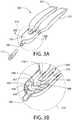
- FIG. 3Ais a perspective view of another embodiment of a product dispenser 300, where the product may be an oral care product.
- the storage chamber 101 and the storage chamber 103may be configured to lie side by side, such that pressure or force may be easily applied to either of the storage chamber 101 or the storage chamber 103 without affecting the other, if desired.
- the mixing chamber 105 and the inlets 107 and 109form a U-shape, with the storage chamber 101 attaching to one arm of the U, the storage chamber 103 attaching to the other arm of the U, and the dispensing nozzle 106 connected to the bottom curve of the U.
- the dispensing nozzle 106may be blocked and unblocked by a tip 111 that is dimensioned to fit partially inside of the dispensing nozzle 106.
- the tip 111may be a snap-off tip 111 that is manufactured as a removable part of the dispensing nozzle 106.
- each of the first storage chamber 101 and the second storage chamber 103may be kept partially or fully segregated or separated from one another by a seal (not shown) in the mixing chamber 105 or by two seals (not shown) in the inlet 109 and the inlet 107.
- a single sealmay be located, for example, between the sidewalls 302 at the entrance to the mixing chamber 105 through which the contents of the storage chambers 101 and 103 flow.
- two sealsmay be located in the inlets 107 and 109 through which contents of the storage chambers 101 and 103 flow before reaching the mixing chamber 105.
- the seal(s)may be placed at a location(s) that prevents the contents from one, or both, of the storage chambers 101 and 103 from exiting the storage chambers; or the seal(s) may be placed at a location(s) that prevents the contents from one storage chamber from mixing with the contents of the other storage chamber; or the seal(s) may be placed at a location(s) that prevents the contents from one, or both, of the storage chambers 101 and 103 from entering the mixing chamber 105, among other possibilities.
- the seal or sealsmay be frangible seals, such as seals that break when a sufficient amount of pressure from a liquid content(s) or from air is applied to them.
- the mixing chamber 105includes a mixing volume 306, which may be in the form of a manifold comprising a plurality of baffles defined by sidewalls 302, 304, 308, 309 extending from inner surface portions of the mixing chamber 105.
- the mixing volume 306 of the mixing chamber 105is connected to the two inlets 107 and 109, which couple to a respective one of the two storage chambers 101 and 103.
- either one, or all, of the storage chambers 101 and 103may be detachably connected to the mixing chamber 105, such as may be the case for single-use storage chambers.
- more than two inletsmay couple more than two storage chambers to the mixing chamber 105, such that three or more different contents or ingredients are mixed by the mixing chamber 105.
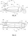
- FIG. 4is a perspective view of an example of a product dispenser 400, where the product may be an oral care product, and illustrates a roller 420 (not to scale) that may be used to dispense mixed contents or a mixed formulation from the dispenser 400.
- the dispenser 400 of FIG. 4which may include any of the features of the dispensers 100, 200 or 300 so far described, at least one of the two storage chambers 101 and 103 may include an anchor portion 113.
- Anchor portion 113includes a surface 115 and a slot or hole 117 formed through surface 115.
- the anchor portion 113engages with a pin or other part of a product applicator (e.g., oral care product applicator 500 shown in FIG.
- a product applicatore.g., oral care product applicator 500 shown in FIG.
- an actuatorsuch as roller 420
- the dispenser 400may be applied to the dispenser 400 (e.g., rolled in a direction 425), such that contents from either or both of the two storage chambers 101 and 103 are pressurized to a pressure great enough to fracture, break or otherwise compromise a seal(s), such as a frangible seal, and such that the contents are squeezed into the mixing chamber 105, where they are sufficiently mixed to form a mixed formulation 427, which exits the dispensing nozzle 106.
- the mixed formulation 427is an oral care product, such as a whitening tooth gel formulation.
- the roller 420may include a surface 421 that is brought into contact with at least one of the two storage chambers 101 and 103, and moved in the direction 425. To keep the actuator aligned, the roller may include guiders 423 which may be accepted along a corresponding track or slot portion (not shown) of the product applicator 500.
- FIG. 5is a cross-sectional view of a product applicator 500 that contains and operates the dispenser 400.
- the product applicator 500includes a housing 531, and a volume 530 for receiving a dispenser, such as an oral care product dispenser 400, and an opening 533 through which the dispenser's dispensing nozzle 106 may protrude.
- dispenser 400may be disposed in the housing 531 as shown in FIG. 5 .
- the product applicator 500may further include an actuator, such as the roller 420 (not to scale), for manipulating the dispenser 400 so as to cause a mixture of the contents contained in the storage chamber 101 and the contents contained in the storage chamber 103 to extrude from the dispensing nozzle 106.
- the product applicator 500may contain and operate the dispenser 400 of FIG. 4 , as shown, or any similar dispenser, such as dispenser 100 of FIG. 1 , dispenser 200 of FIG. 2 , or dispenser 300 of FIG. 3 .
- the actuatormay be the roller 420 that may be placed in mechanical communication with the storage chamber 101.
- the roller 420exerts force or pressure on (e.g., squeezes) the storage chamber 101, causing the contents A of the storage chamber 101 to flow into the mixing chamber 105.
- the storage chamber 101exerts force or pressure on (e.g., squeezes) the storage chamber 103 (in conjunction with the housing 531), causing the contents B of the storage chamber 103 to flow into the mixing chamber 105.
- other actuatorsmay be used.
- a second rollerthat contacts the storage chamber 103, and that moves the direction 425 on a path approximately parallel to and in tandem with the movement of the roller 420 may be used.
- the actuatormay be a rotating element (not shown) that may be placed in mechanical communication with the two storage chambers 101 and 103, and the two storage chambers 101 and 103 may be configured to rotate in response to movement of the rotating element.
- the two storage chambers 101 and 103may be configured such that they twist around one another as the rotating element rotates. As a result of the twisting, the contents of the storage chambers 101 and 103 may be pressurized so as to fracture a seal(s), and so that the contents A and B may flow into the mixing chamber 105.
- FIG. 6is a perspective view of another example of a product dispenser 600.
- the product dispenser 600includes a first storage chamber 101 and a second storage chamber 103, which may be a thermoformed unit having an internal separator wall that separates the first storage chamber and the second storage chamber. Distal ends of the first and second storage chambers may connect with inlets (not visible) of a mixing chamber 105. A frangible seal (not visible) may be located in the inlets to keep contents in the first and second storage chambers separated.
- Dispenser 600includes an anchor portion 113.
- Anchor portion 113includes a surface 115 and a slot or hole 117 formed through surface 115.
- Anchor portion 113engages with a pin or other part of a product applicator 700 (e.g., oral care product applicator 700 shown in FIG. 7 ) in order to capture and hold the dispenser 600 and keep it in place.
- a product applicator 700e.g., oral care product applicator 700 shown in FIG. 7
- an actuatorsuch as wedge, platen or piston, may be controlled by user interface 760 (shown in FIG. 7 ) to traverse a length of the dispenser 600, such as in a distal direction along groove 551.
- the actuatormay be configured with a geometry that allows it to cause walls of chambers 101 and 103 to collapse, such that contents from either or both of the two storage chambers 101 and 103 are pressurized to a pressure great enough to fracture, break or otherwise compromise a seal(s), such as frangible seals located in the inlets to the mixing chamber. Accordingly, contents are squeezed out of their respective storage chambers and into the mixing chamber 105, where they are sufficiently mixed to form a mixed formulation, which exits the dispensing nozzle at, for example, the distal end of mixing chamber 105.
- FIG. 7shows an external perspective view of an embodiment of an oral-care product applicator 700.
- Oral-care product applicator 700may include some or all of the features of the product applicator 500 of FIG. 5 .
- the oral care product applicator 700includes a housing 761 having a volume in which a dispenser, such as the dispenser 600 may be placed.
- One end 770 of the applicator 700may include an anchor (not shown) which accepts the anchor portion 113 of the dispenser 600, for example by engaging the hole 117 with a pin or hook (not shown) that is inside of the end 770.
- Another end of the applicator 700may include a detachable end-cap 780 that is removed in order to insert the dispenser 600 into the housing 761.
- the detachable end-cap 780When attached back on housing 761, the detachable end-cap 780 accepts the mixing chamber 105 of the dispenser 600 and has a distal opening 533 through which the dispenser's dispensing nozzle 106 may protrude. In some embodiments, the end-cap 780 comprises the dispensing nozzle 106.
- the oral-care product applicator 700includes a user interface 760 that may be employed by a user to activate or move an actuator (not visible) disposed in the housing 761, such as the roller 420, a wedge, a platen or a piston, as described above.
- the user interface 760may include a sliding button 765 that moves along a ratchet track 767 toward the removable end-cap 780.
- the sliding button 765may include pins or teeth (not visible) that engage the ratchet track 767 and preclude or prevent the sliding button 765 from moving back away from the removable end-cap 780.
- the sliding buttonmoves distally toward the detachable end-cap 780, it actuates an actuator, such as roller 420, wedge, platen or piston to move in the same direction.
- an actuatorsuch as roller 420, wedge, platen or piston to move in the same direction.
- the actuatortraverses a length of the dispenser 600 toward the mixing chamber 105.
- movement of the sliding button 765 along ratchet track 767causes movement of an actuator within housing 761 along groove 551 of dispenser 600.
- Such movementcauses the actuator to apply pressure against the first and second storage chambers 101 and 103, thereby pressurizing contents therein to flow into the mixing chamber 105.
- the user interface 760may include a push button, a rotating knob, a gear drive, a cam assembly, or other mechanism that applies force or pressure, either directly or indirectly, to the storage chambers 101 and 103, which force or pressure causes the contents of the storage chambers 101 and 103 to flow into the mixing chamber 105 and causes the sufficiently mixed contents to then flow out of the dispensing nozzle 106.
- any or all of the housing 761, the storage chambers 101 and 103, the removable end-cap 780, and/or the mixing chamber 105may include a viewing window. That is, any or all of the housing 761, the storage chambers 101 and 103, the removable end-cap 780, and/or the mixing chamber 105 be formed of a transparent or semi-transparent material or may include a transparent or semi-transparent portion through which their current contents are visible.
- the transparent materialmay be a clear plastic or other suitable see-through material which allows a user to view the contents that are inside the housing 761, the storage chambers 101 and 103, the removable end-cap 780, and/or the mixing chamber 105.
Landscapes
- Engineering & Computer Science (AREA)
- Mechanical Engineering (AREA)
- Health & Medical Sciences (AREA)
- Life Sciences & Earth Sciences (AREA)
- Dentistry (AREA)
- Epidemiology (AREA)
- Oral & Maxillofacial Surgery (AREA)
- Animal Behavior & Ethology (AREA)
- General Health & Medical Sciences (AREA)
- Public Health (AREA)
- Veterinary Medicine (AREA)
- Package Specialized In Special Use (AREA)
- Containers And Packaging Bodies Having A Special Means To Remove Contents (AREA)
Description
- Sachets, also known as pouches or packets, are known in the art. Sachets are small packets that are used for supplying small doses of a product. These are used to dispense single or a small number of doses of adhesives, lubricants, medicines, cosmetics, shampoos, conditioners, liquid soaps, lotions or dentifrices, and the like. In some instances a single dose is a sample amount. Thus, in some instances the sachets will be used to deliver a single dose of a single substance. However, in other instances they will be used to dispense doses of two different substances. In an example, two or more different substances may each be stored in a single sachet that keeps the substances separate. Accordingly, dual chamber, or multi-chamber sachets are provided for storing different substances.
- In instances of delivery of two different substances, sometimes these substances must be delivered substantially uniformly. That is, each of the substances should be dispensed in about equal amounts. This is needed for the effective use of the substances being dispensed. Meanwhile, in some instances, the substances include components that are reactive and must be dispensed separately, such as in a certain reactive ratio, for mixing after dispensing. Some medications also must be used in a certain or specific ratio. The same is the case for a dentifrice that is comprised of two reactive or non-compatible components, for example, a tooth-whitening component and a coloring component. These types of substances need sachets that not only keep their respective components separate, for example, during storage (e.g., before use), but that also reliably dispense the components from each sachet or chamber in substantially uniform and/or predetermined amounts or proportions. However, conventional sachets do not provide for the contents therein to be segregated from each other during storage and then dispensed in a usable, predetermined, ratio as a mixture. An improved sachet that overcomes the limitations of conventional sachets would be a welcome addition to the art.
US 2012 / 0 267 394 A1 discloses a dispensing device comprising a rack and a pinion driven by a set of worm screws. A cartridge comprising two separate pouches is placed within the rack assembly, which may include rollers for assisting in the extrusion of dental material from the cartridge.US 2007 / 0 253 761 A1 discloses a manually squeezed dispenser for expelling a product therefrom.- From
WO 00 / 10 423 - Moreover, from
EP 1 136 091 A1 - The invention relates to an oral care product applicator according to
claim 1. Further embodiments of the invention can be gathered from the dependent claims. - A product dispenser may be used for oral care products. The oral care product dispenser includes at least two storage chambers, a mixing chamber, a dispensing nozzle in fluidic communication with the mixing chamber and at least one seal that keeps contents stored in the at least two storage chambers separated during storage. The mixing chamber receives and sufficiently mixes contents from the at least two storage chambers during dispensing.
- In an embodiment of the invention, there is a product applicator that may be used with oral care products. The oral care product applicator comprises a housing having a volume for receiving a dispenser, a dispenser disposed in the housing, and an actuator for manipulating the dispenser. The dispenser includes at least two storage chambers, a mixing chamber that receives and sufficiently mixes contents from the at least two storage chambers, a dispensing nozzle in fluid communication with the mixing chamber, and at least one seal that keeps contents stored in the at least two storage chambers from exiting the dispenser.
- Further areas of applicability of the present invention will become apparent from the detailed description provided hereinafter. It should be understood that the detailed description and specific examples, while indicating the preferred embodiment of the invention, are intended for purposes of illustration only and are not intended to limit the scope of the invention.
- The present invention will become more fully understood from the detailed description and the accompanying drawings, wherein:
FIG. 1 is a cross-sectional view of a product dispenser of an embodiment.FIG. 2 is a perspective view of the product dispenser ofFIG. 1 with the storage chambers spread apart;FIG. 3A is a perspective view of a product dispenser of an embodiment;FIG. 3B is a cross-sectional, perspective, close-up view of a mixing chamber and nozzle of the product dispenser ofFIG. 3A ;FIG. 4 is a perspective view of an oral care product dispenser of an embodiment and illustrates a roller being used to dispense mixed contents from the dispenser;FIG. 5 is a cross-sectional view of an oral care product applicator of an embodiment;FIG. 6 is a perspective view of an oral care product dispenser an embodiment; andFIG. 7 is a perspective view of an oral care product applicator of an embodiment.- The following description of the preferred embodiments is merely exemplary in nature and is in no way intended to limit the invention, its application, or uses.
- As used throughout, ranges are used as shorthand for describing each and every value that is within the range. Any value within the range can be selected as the terminus of the range. In the event of a conflict in a definition in the present disclosure and that of a cited reference, the present disclosure controls.
- As used herein, the terms "sufficiently mix" and "sufficiently mixed" mean an amount or degree of mixing of components such that the components contact each other and could, can, or will react with each other. In various implementations where the components are reactive in manner making them incompatible for storage before use in contact with each other, the components may be segregated from one another when not in use; i.e., prevented from sufficiently mixing when not in use. As used here, the term "incompatible" to describe components of a formulation, means that over time (e.g., during storage before use), the mixing of the components deemed "incompatible" degrades one or more desired quality of the combined formulation.
- Embodiments described herein generally provide for the delivery of two reactive and/or incompatible components (A and B) and for sufficiently mixing the components into a formulation, such as a ready-to-use formulation, just prior to use. Multiple components, such as components A and B, are packaged in separate storage chambers of a dispenser, such as in separate sachets of a dual chamber sachet. Each storage chamber is separated from the other by a seal, such as a frangible seal. A mixing chamber, through which components A and B may flow, serves or functions to sufficiently mix the components into, for example, a ready-to-use formulation, such as a homogenous mixture. The mixing chamber may be configured with a tortuous path and/or any other geometry and/or features defining a conduit through which the components from the storage chamber may flow and sufficiently mix.
- Form/Fill/Seal equipment may be used to manufacture embodiments of a dispenser that includes separate storage chambers, such as a dual sachet, and a mixing chamber. This manufacturing process is economical and could also be used to produce blown tubes and thermoformed containers for use as the storage chambers. For example, a dispenser may include a container with thermoformed dual storage chambers in place of sachets. In one embodiment, a dispensing nozzle is connected to or comprises part of the mixing chamber. A seal on the end of the dispensing nozzle of the mixing chamber can be removed by the consumer. In an embodiment, squeezing the two storage chambers, such as two sachets, together will fracture a frangible seal in each chamber and force components A and B into the mixing chamber where they are combined and sufficiently mixed to form a ready-to-use formulation before exiting the dispensing nozzle.
- Another embodiment uses a dual sachet as the two storage chambers, in connection with a mixing chamber that may be used in conjunction with an applicator that includes an actuator and a user interface for controlling the actuator. A housing of the applicator may be opened, and a dispenser, such as the dual sachet with mixing chamber, can be positioned inside. For example, a dispensing nozzle may be positioned at one end of the applicator and an anchor for attaching the ends of the dispenser's sachets may be included at the other end. When the cover is closed and the consumer actuates the system by manipulating the actuator, a homogenous mixture of components A and B, each stored in a separate sachet, may be formed in the mixing chamber as a ready-to-use formulation, which may be dispensed through the dispensing nozzle.
- The actuator may approximately evenly squeeze the sachets and force each of the components out of each of the sachets and through the mixing chamber. The actuator may be one or more of a roller wheel(s) that squeezes the sachets, starting at an end opposing the dispensing nozzle, a clamping platen that exerts pressure on both sachets, or a rotating component that twists the sachets, to name a few possible implementations.
- The actuator may be controlled by a user interface. In an example, the user interface may be a sliding button, push button or rotating knob and may communicate with a ratchet track, gear drive, cam assembly or other mechanisms known in art.
- Transparent portions, such as viewing windows, can be designed into the applicator and/or the product dispenser so that the user can see, for example, the contents contained in the storage chambers (e.g., the sachets) or in the mixing chamber. In an example, the viewing windows may be configured to provide the user with the ability to see components A and B separately, and then again when the components have been combined, for example, as the ready-to-use formulation in the mixing chamber. Consumer research has shown that viewing the components and providing a visual cue that they have been mixed correctly is perceived positively and builds confidence.
- In some embodiments, the dispenser may be designed to be single use. For example, in an embodiment, the two storage chambers or sachets may be disposed of after a single application, which promotes good hygiene. However, it is feasible to size the two storage chambers to contain enough of the components for multiple applications of a ready-to-use mixed formulation. Moreover, the actuator in combination with the user interface can be designed to meter the correct amount of contents and product formulation for each application.
- Embodiments described herein may be used for storing, transporting and dispensing materials, such as gels, powders, solids, and may also be used for transporting and dispensing liquids and pastes of varying viscosities. In some embodiments, the two storage chambers may be used to store different forms of materials, such as a solid in one chamber and a liquid in the other chamber. In the case of an oral care teeth whitening product, any of the embodiments described herein may be used to mix and apply components A and B, for example, as components of the oral care teeth whitening system, either directly to the teeth or into a tray or other receptacle. In an oral care teeth whitening system, whitening ingredients, such as hydrogen peroxide, react with coloring ingredients, such as blue dye, which may be used as decorative colorant in a paste, and cause the blue color to fade. Accordingly, in an example, component A may include the hydrogen peroxide and component B may include the blue dye. In another example, component A may include a base formulation and component B may include an enzyme or a catalyst such that when combined with component A, produces a mixture that can deliver a desired benefit, such as a whitening benefit, a sensitivity reduction benefit, a plague reduction benefit. In a further example, component A may include a substrate and component B may include an enzyme, e.g., glucose and glucose oxidase.
- Embodiments of the invention will now be described with reference to the drawings.
FIG. 1 is a cross-sectional view of aproduct dispenser 100, where the product may be an oral care product. The dispenser may include two storage chambers, 101 and 103 (holding contents A and contents B), a mixingchamber 105 that receives and sufficiently mixes contents from the two storage chambers, and a dispensingnozzle 106 in fluidic communication with the mixing chamber. In other embodiments, more than twostorage chambers - In an example, the contents comprise first contents disposed in a first one of the at least two storage chambers, second contents disposed in a second one of the at least two storage chambers. At least one of the first and the second contents may comprise an oral care product. In an example, contents from each of the storage chamber are mixed in the mixing chamber. The dispensing nozzle receives the mixed contents from the mixing chamber and the mixed contents may include an oral care product.
- A
seal 102 and aseal 104 keep contents stored in the two storage chambers separated during storage. In the embodiment shown, theseal 102 may be disposed between the mixingchamber 105 and thestorage chamber 101, on the end of theinlet 109, and theseal 104 may be disposed between the mixingchamber 105 and thestorage chamber 103, on the end of theinlet 107. Each of theseals chamber 105 until each seal is fractured or broken or otherwise compromised. In some embodiments, there may be a single seal instead of two seals as shown. For example, in such embodiments, theinlets chamber 105 to form a single inlet into the mixingchamber 105, and the single seal may cover the single inlet. In some embodiments, a single seal may be formed in one of the storage chambers (101 or 103) by heat, such as via a heat plate, ultrasonic welding, etc. - In various embodiments, a seal may be made of a polymer film or a metal foil. In an embodiment, a seal may be removed or punctured by the user. In an embodiment, a seal may be a frangible seal. In such an embodiment, the frangible seal may include or may be made of a material that fractures or otherwise compromises upon exposure to sufficient force or pressure, such as the force or pressure exerted on the seal by the contents of one or both of the
storage chambers storage chambers chamber 105 and thestorage chambers storage chambers inlets chamber 105. - Each of the at least two
storage chambers inlets chamber 105. As shown inFIG. 2 , thefirst storage chamber 101 and thesecond storage chamber 103 may each be a portion of a dualchamber sachet dispenser 200 and may be formed separate from one another. Thestorage chambers seal 102 and theseal 104. A storage chamber may include an internal volume defined by outer walls. These walls can be a monolayer or a multilayer film structure. Suitable films for the monolayer or multilayer can be selected from polyethylene (PET), aluminum foil, terephthalate; polyacrylonitrile and polystyrene resin (Barex); biaxially oriented polypropylene (BOPP); low density polyethylene (LDPE); polyethylene (PE); and ethylene-vinyl alcohol copolymer (EVOH) nylon. FIG. 3A is a perspective view of another embodiment of aproduct dispenser 300, where the product may be an oral care product. As shown in the embodiment ofFIG. 3A , thestorage chamber 101 and thestorage chamber 103 may be configured to lie side by side, such that pressure or force may be easily applied to either of thestorage chamber 101 or thestorage chamber 103 without affecting the other, if desired. In the embodiment ofFIG. 3A , the mixingchamber 105 and theinlets storage chamber 101 attaching to one arm of the U, thestorage chamber 103 attaching to the other arm of the U, and the dispensingnozzle 106 connected to the bottom curve of the U. The dispensingnozzle 106 may be blocked and unblocked by atip 111 that is dimensioned to fit partially inside of the dispensingnozzle 106. In various embodiments thetip 111 may be a snap-off tip 111 that is manufactured as a removable part of the dispensingnozzle 106.- Referring now to the zoomed-in
view 310 inFIG. 3B , the contents of each of thefirst storage chamber 101 and thesecond storage chamber 103 may be kept partially or fully segregated or separated from one another by a seal (not shown) in the mixingchamber 105 or by two seals (not shown) in theinlet 109 and theinlet 107. In various embodiments, a single seal (not shown) may be located, for example, between thesidewalls 302 at the entrance to the mixingchamber 105 through which the contents of thestorage chambers inlets storage chambers chamber 105. While not limited to any particular location, the seal(s) may be placed at a location(s) that prevents the contents from one, or both, of thestorage chambers storage chambers chamber 105, among other possibilities. In various embodiments, the seal or seals may be frangible seals, such as seals that break when a sufficient amount of pressure from a liquid content(s) or from air is applied to them. - As illustrated in the zoomed-in
view 310 of the example inFIG. 3B , the mixingchamber 105 includes a mixingvolume 306, which may be in the form of a manifold comprising a plurality of baffles defined by sidewalls 302, 304, 308, 309 extending from inner surface portions of the mixingchamber 105. The mixingvolume 306 of the mixingchamber 105 is connected to the twoinlets storage chambers - It is noted that either one, or all, of the
storage chambers chamber 105, such as may be the case for single-use storage chambers. Also, as noted above, in alternative embodiments, more than two inlets may couple more than two storage chambers to the mixingchamber 105, such that three or more different contents or ingredients are mixed by the mixingchamber 105. FIG. 4 is a perspective view of an example of aproduct dispenser 400, where the product may be an oral care product, and illustrates a roller 420 (not to scale) that may be used to dispense mixed contents or a mixed formulation from thedispenser 400. As shown by thedispenser 400 ofFIG. 4 , which may include any of the features of thedispensers storage chambers anchor portion 113.Anchor portion 113 includes asurface 115 and a slot orhole 117 formed throughsurface 115. In various embodiments, theanchor portion 113 engages with a pin or other part of a product applicator (e.g., oralcare product applicator 500 shown inFIG. 5 ) in order to capture and hold thedispenser 400 and keep it in place. Once anchored in theapplicator 500, an actuator, such asroller 420, may be applied to the dispenser 400 (e.g., rolled in a direction 425), such that contents from either or both of the twostorage chambers chamber 105, where they are sufficiently mixed to form amixed formulation 427, which exits the dispensingnozzle 106. In some embodiments, themixed formulation 427 is an oral care product, such as a whitening tooth gel formulation.- The
roller 420 may include asurface 421 that is brought into contact with at least one of the twostorage chambers direction 425. To keep the actuator aligned, the roller may includeguiders 423 which may be accepted along a corresponding track or slot portion (not shown) of theproduct applicator 500. FIG. 5 is a cross-sectional view of aproduct applicator 500 that contains and operates thedispenser 400. Theproduct applicator 500 includes ahousing 531, and avolume 530 for receiving a dispenser, such as an oralcare product dispenser 400, and anopening 533 through which the dispenser'sdispensing nozzle 106 may protrude. Thus,dispenser 400 may be disposed in thehousing 531 as shown inFIG. 5 . Theproduct applicator 500 may further include an actuator, such as the roller 420 (not to scale), for manipulating thedispenser 400 so as to cause a mixture of the contents contained in thestorage chamber 101 and the contents contained in thestorage chamber 103 to extrude from the dispensingnozzle 106. Theproduct applicator 500 may contain and operate thedispenser 400 ofFIG. 4 , as shown, or any similar dispenser, such asdispenser 100 ofFIG. 1 ,dispenser 200 ofFIG. 2 , ordispenser 300 ofFIG. 3 .- As discussed above, the actuator may be the
roller 420 that may be placed in mechanical communication with thestorage chamber 101. As noted above, when theroller 420 is moved indirection 425, it exerts force or pressure on (e.g., squeezes) thestorage chamber 101, causing the contents A of thestorage chamber 101 to flow into the mixingchamber 105. Similarly and at the same time thestorage chamber 101 exerts force or pressure on (e.g., squeezes) the storage chamber 103 (in conjunction with the housing 531), causing the contents B of thestorage chamber 103 to flow into the mixingchamber 105. In various embodiments, other actuators may be used. For example, a second roller (not shown) that contacts thestorage chamber 103, and that moves thedirection 425 on a path approximately parallel to and in tandem with the movement of theroller 420 may be used. In another example, the actuator may be a rotating element (not shown) that may be placed in mechanical communication with the twostorage chambers storage chambers storage chambers storage chambers chamber 105. FIG. 6 is a perspective view of another example of aproduct dispenser 600. As shown inFIG. 6 , theproduct dispenser 600 includes afirst storage chamber 101 and asecond storage chamber 103, which may be a thermoformed unit having an internal separator wall that separates the first storage chamber and the second storage chamber. Distal ends of the first and second storage chambers may connect with inlets (not visible) of a mixingchamber 105. A frangible seal (not visible) may be located in the inlets to keep contents in the first and second storage chambers separated.Dispenser 600 includes ananchor portion 113.Anchor portion 113 includes asurface 115 and a slot orhole 117 formed throughsurface 115.Anchor portion 113 engages with a pin or other part of a product applicator 700 (e.g., oralcare product applicator 700 shown inFIG. 7 ) in order to capture and hold thedispenser 600 and keep it in place. Once anchored in theapplicator 700, an actuator, such as wedge, platen or piston, may be controlled by user interface 760 (shown inFIG. 7 ) to traverse a length of thedispenser 600, such as in a distal direction alonggroove 551. In an embodiment, as the actuator traverses alonggroove 551, it may be configured with a geometry that allows it to cause walls ofchambers storage chambers chamber 105, where they are sufficiently mixed to form a mixed formulation, which exits the dispensing nozzle at, for example, the distal end of mixingchamber 105.FIG. 7 shows an external perspective view of an embodiment of an oral-care product applicator 700. Oral-care product applicator 700 may include some or all of the features of theproduct applicator 500 ofFIG. 5 . The oralcare product applicator 700 includes ahousing 761 having a volume in which a dispenser, such as thedispenser 600 may be placed. Oneend 770 of theapplicator 700 may include an anchor (not shown) which accepts theanchor portion 113 of thedispenser 600, for example by engaging thehole 117 with a pin or hook (not shown) that is inside of theend 770. Another end of theapplicator 700 may include a detachable end-cap 780 that is removed in order to insert thedispenser 600 into thehousing 761. When attached back onhousing 761, the detachable end-cap 780 accepts the mixingchamber 105 of thedispenser 600 and has adistal opening 533 through which the dispenser'sdispensing nozzle 106 may protrude. In some embodiments, the end-cap 780 comprises the dispensingnozzle 106.- The oral-
care product applicator 700 includes auser interface 760 that may be employed by a user to activate or move an actuator (not visible) disposed in thehousing 761, such as theroller 420, a wedge, a platen or a piston, as described above. While not limited to any particular embodiment, in the example shown inFIG. 7 , theuser interface 760 may include a slidingbutton 765 that moves along aratchet track 767 toward the removable end-cap 780. The slidingbutton 765 may include pins or teeth (not visible) that engage theratchet track 767 and preclude or prevent the slidingbutton 765 from moving back away from the removable end-cap 780. As the sliding button moves distally toward the detachable end-cap 780, it actuates an actuator, such asroller 420, wedge, platen or piston to move in the same direction. Thus, withdispenser 600 disposed within theapplicator 700, the actuator traverses a length of thedispenser 600 toward the mixingchamber 105. In an example, movement of the slidingbutton 765 alongratchet track 767 causes movement of an actuator withinhousing 761 alonggroove 551 ofdispenser 600. Such movement causes the actuator to apply pressure against the first andsecond storage chambers chamber 105. - In other implementations, the
user interface 760 may include a push button, a rotating knob, a gear drive, a cam assembly, or other mechanism that applies force or pressure, either directly or indirectly, to thestorage chambers storage chambers chamber 105 and causes the sufficiently mixed contents to then flow out of the dispensingnozzle 106. - In various embodiments, any or all of the
housing 761, thestorage chambers cap 780, and/or the mixingchamber 105 may include a viewing window. That is, any or all of thehousing 761, thestorage chambers cap 780, and/or the mixingchamber 105 be formed of a transparent or semi-transparent material or may include a transparent or semi-transparent portion through which their current contents are visible. For example, the transparent material may be a clear plastic or other suitable see-through material which allows a user to view the contents that are inside thehousing 761, thestorage chambers cap 780, and/or the mixingchamber 105.
Claims (15)
- An oral care product applicator (500, 700), comprising:a housing (531, 761) comprising a volume (530) for receiving a dispenser (100, 200, 300, 400, 600);a dispenser (100, 200, 300, 400, 600) disposed in the housing (531, 761), andan actuator for manipulating the dispenser (100, 200, 300, 400, 600),wherein the dispenser comprises:at least two storage chambers (101, 103),at least one seal (102, 104) that keeps contents stored in the at least two storage chambers (101, 103) from exiting the dispenser,a mixing chamber (105), connected to the at least two storage chambers (101, 103), that receives and sufficiently mixes contents from the at least two storage chambers (101, 103), anda dispensing nozzle (106) in fluid communication with the mixing chamber (105),characterized in thatat least one of the at least two storage chambers (101, 103) comprises an anchor portion (113) that engages with the housing (531, 761), wherein the anchor portion (113) comprises a surface (115) and a slot (117) formed through the surface (115), and wherein the dispensing nozzle (106) is positioned at one end of the applicator (500, 700) and the anchor portion (113) is positioned at another end of the applicator.
- The oral care product applicator of claim 1, wherein the at least one seal (102, 104) is disposed between the mixing chamber (105) and the at least two storage chambers (101, 103).
- The oral care product applicator of claim 1, wherein the at least two storage chambers (101, 103) comprise a sidewall; and wherein the seal (102, 104) comprises a material that fractures upon exposure to a pressure that is less than a pressure required to fracture the sidewall of the at least two storage chambers (101, 103).
- The oral care product applicator of claim 1, wherein the mixing chamber (105) comprises a manifold comprising:at least two inlets (109, 107); anda mixing volume (306) comprising:
a plurality of baffles defined by a plurality of sidewalls (302, 304, 308, 309) extending from an inner surface of the mixing chamber (105). - The oral care product applicator of claim 1, wherein the dispensing nozzle (106) extends from the mixing chamber (105) and comprises a snap-off tip (111).
- The oral care product applicator of claim 1, wherein the contents comprise first contents disposed in a first one of the at least two storage chambers (101, 103) and second contents disposed in a second one of the at least two storage chambers (101, 103); and wherein at least one of the first and the second contents comprise an oral care product.
- The oral care product applicator of claim 1, wherein the at least one seal (102, 104) keeps contents stored in the at least two storage chambers (101, 103) separate during storage.
- The oral care product applicator of claim 1, wherein the anchor portion (113) engages with a pin of the applicator (500, 700) to capture and hold the dispenser (100, 200, 300, 400, 600) in place.
- The oral care product applicator of claim 1, wherein the actuator comprises at least one roller (420) in mechanical communication with at least one of the at least two storage chambers (101, 103).
- The oral care product applicator of claim 1, wherein the actuator comprises at least one of a group consisting of a clamping platen, a rotating element and a piston, and wherein the actuator is in mechanical communication with at least one of the at least two storage chambers (101, 103).
- The oral care product applicator of claim 1, wherein each of the at least two storage chambers (101, 103) comprise separate sachets, the mixing chamber (105) comprises at least two inlets (109, 107), and
each of the separate sachets connect to a respective one of the at least two inlets (109, 107) of the mixing chamber (105). - The oral care product applicator of claim 1, wherein the actuator is controlled by a user interface (760).
- The oral care product applicator of claim 12, wherein the user interface (760) comprises at least one of a group comprising a sliding button (765), a push button and a rotating knob; and
wherein the user interface (760) communicates with at least one of a group comprising a ratchet (767), a gear drive, a cam assembly and a piston. - The oral care product applicator of claim 1, wherein at least one of the at least two storage chambers (101, 103), the housing, and the mixing chamber (105) comprise a transparent portion.
- The oral care product applicator of claim 1, wherein the at least one seal (102, 104) comprises a frangible seal that fractures from pressure caused by the actuator.
Applications Claiming Priority (1)
| Application Number | Priority Date | Filing Date | Title |
|---|---|---|---|
| PCT/US2015/019598WO2016144326A1 (en) | 2015-03-10 | 2015-03-10 | Multi chamber delivery system |
Publications (2)
| Publication Number | Publication Date |
|---|---|
| EP3259199A1 EP3259199A1 (en) | 2017-12-27 |
| EP3259199B1true EP3259199B1 (en) | 2019-10-02 |
Family
ID=52686530
Family Applications (1)
| Application Number | Title | Priority Date | Filing Date |
|---|---|---|---|
| EP15710703.8AActiveEP3259199B1 (en) | 2015-03-10 | 2015-03-10 | Multi chamber delivery system |
Country Status (9)
| Country | Link |
|---|---|
| US (1) | US20180022526A1 (en) |
| EP (1) | EP3259199B1 (en) |
| CN (1) | CN107427343A (en) |
| AR (1) | AR104482A1 (en) |
| AU (1) | AU2015385862B2 (en) |
| IL (1) | IL253855A0 (en) |
| MX (1) | MX2017011265A (en) |
| TW (1) | TW201700356A (en) |
| WO (1) | WO2016144326A1 (en) |
Families Citing this family (14)
| Publication number | Priority date | Publication date | Assignee | Title |
|---|---|---|---|---|
| WO2017030576A1 (en) | 2015-08-19 | 2017-02-23 | Colgate-Palmolive Company | Multi-chemistry dispenser |
| EP3162726A1 (en)* | 2015-10-30 | 2017-05-03 | HILTI Aktiengesellschaft | Multi-chamber film bag and its use |
| US10543956B2 (en)* | 2016-08-22 | 2020-01-28 | James Alexander Corporation | Dispenser and process |
| FR3067913B1 (en)* | 2017-06-23 | 2021-06-11 | Seb Sa | APPARATUS FOR MANUFACTURING A COMPOSITION |
| FR3067912B1 (en)* | 2017-06-23 | 2019-07-19 | Seb S.A. | MANUFACTURING APPARATUS FOR MANUFACTURING A COMPOSITION |
| FR3067910B1 (en) | 2017-06-23 | 2021-06-18 | Seb Sa | APPARATUS FOR MANUFACTURING A PERSONALIZED COSMETIC PRODUCT |
| EP3755642A4 (en)* | 2018-02-20 | 2021-11-10 | Johnson Living Trust | Dual container for sterile fabrication and filling |
| KR20210008853A (en) | 2018-06-29 | 2021-01-25 | 더 프록터 앤드 갬블 캄파니 | Dual phase product distributor |
| KR20210008861A (en) | 2018-06-29 | 2021-01-25 | 더 프록터 앤드 갬블 캄파니 | Dual phase product |
| WO2020005787A2 (en) | 2018-06-29 | 2020-01-02 | The Procter & Gamble Company | Dual phase products |
| WO2020006327A1 (en) | 2018-06-29 | 2020-01-02 | The Procter & Gamble Company | Dual phase products |
| US10836539B1 (en)* | 2019-05-07 | 2020-11-17 | The Boeing Company | Selectable volume precision liquid dispenser |
| JP7319401B2 (en) | 2019-07-09 | 2023-08-01 | ザ プロクター アンド ギャンブル カンパニー | Multi-composition product dispenser |
| EP3996851B1 (en) | 2019-07-09 | 2024-08-07 | The Procter & Gamble Company | Multi-composition product dispenser |
Family Cites Families (12)
| Publication number | Priority date | Publication date | Assignee | Title |
|---|---|---|---|---|
| US5386928A (en)* | 1993-11-15 | 1995-02-07 | Minnesota Mining And Manufacturing Company | Dual collapsible tube dispensing assembly |
| US5490613A (en)* | 1994-07-07 | 1996-02-13 | The Clorox Company | Viscous fluid dispenser |
| US5573143A (en)* | 1994-09-21 | 1996-11-12 | Colgate-Palmolive Company | Blow molded multi-chamber containers with dispenser/doser |
| US5881921A (en)* | 1997-05-06 | 1999-03-16 | The Plastek Group | Product dispenser having separable refill top loading cartridge |
| US6168335B1 (en)* | 1998-08-18 | 2001-01-02 | Arich, Inc. | Applicator and dispensing device using same |
| DE10012886A1 (en)* | 2000-03-16 | 2001-09-20 | Transcoject Gmbh | Cannula |
| US20020134801A1 (en)* | 2001-03-26 | 2002-09-26 | Stewart David A. | First use flow-delay membrane for pourable containerized motor oils and other viscous fluids |
| JP4332444B2 (en)* | 2004-02-17 | 2009-09-16 | 東洋製罐株式会社 | Double structure aerosol can container for hair dye and interior pouch housed in aerosol can container |
| US7976234B2 (en)* | 2006-04-28 | 2011-07-12 | James Alexander Corporation | Multi-chambered dispenser and process |
| KR100867459B1 (en)* | 2007-07-13 | 2008-11-10 | 이명섭 | Hair dye mixing brush |
| WO2012145462A1 (en)* | 2011-04-19 | 2012-10-26 | Dentsply International Inc. | Impression material delivery system |
| KR20130086695A (en)* | 2012-01-26 | 2013-08-05 | 이권행 | Dual type tube vessel and the method of making it |
- 2015
- 2015-03-10WOPCT/US2015/019598patent/WO2016144326A1/ennot_activeCeased
- 2015-03-10MXMX2017011265Apatent/MX2017011265A/enunknown
- 2015-03-10AUAU2015385862Apatent/AU2015385862B2/enactiveActive
- 2015-03-10CNCN201580077488.0Apatent/CN107427343A/enactivePending
- 2015-03-10EPEP15710703.8Apatent/EP3259199B1/enactiveActive
- 2015-03-10USUS15/556,897patent/US20180022526A1/ennot_activeAbandoned
- 2016
- 2016-03-02ARARP160100552Apatent/AR104482A1/enunknown
- 2016-03-08TWTW105106980Apatent/TW201700356A/enunknown
- 2017
- 2017-08-06ILIL253855Apatent/IL253855A0/enunknown
Non-Patent Citations (1)
| Title |
|---|
| None* |
Also Published As
| Publication number | Publication date |
|---|---|
| AU2015385862B2 (en) | 2018-10-18 |
| MX2017011265A (en) | 2018-01-12 |
| TW201700356A (en) | 2017-01-01 |
| CN107427343A (en) | 2017-12-01 |
| AR104482A1 (en) | 2017-07-26 |
| EP3259199A1 (en) | 2017-12-27 |
| US20180022526A1 (en) | 2018-01-25 |
| WO2016144326A1 (en) | 2016-09-15 |
| AU2015385862A1 (en) | 2017-08-24 |
| IL253855A0 (en) | 2017-09-28 |
Similar Documents
| Publication | Publication Date | Title |
|---|---|---|
| EP3259199B1 (en) | Multi chamber delivery system | |
| EP3287384B1 (en) | Multi-chambered dispenser | |
| JP4027390B2 (en) | Equipment for the storage and supply of viscous substances | |
| US20050072442A1 (en) | Self-contained hair-coloring system for touch-up, highlighting and less than full treatment applications | |
| US9045259B2 (en) | Discharge device with tube | |
| EP2699489B1 (en) | Impression material delivery system | |
| US8986313B2 (en) | Multi-component cartridge system with shiftable closures in the cartridges | |
| EP1153881A1 (en) | Multiple-compartment container with tap | |
| US20030121936A1 (en) | Device for dispensing separately packaged products together | |
| US20020036212A1 (en) | Dispensing device and methods | |
| WO2008021641B1 (en) | Method and device for applying hair color | |
| US20150274344A1 (en) | Devices and Methods for Packaging and Dispensing Unit Doses of Personal Care Products | |
| WO2006068934A2 (en) | Devices for storing and dispensing compositions | |
| CA2460871C (en) | Device for storing, mixing and dispensing a free-flowing material | |
| US20090052971A1 (en) | Delivery system | |
| WO2002048002A2 (en) | Package and dispensing actuator for multiple-component compositions | |
| US20090308891A1 (en) | Cartridge | |
| US8418882B2 (en) | Applicator | |
| TW201138983A (en) | Cartridge with closure stopper | |
| US20170247149A1 (en) | Fluid dispensing device | |
| US20070269253A1 (en) | Compound mixing and dispensing device | |
| US10144022B2 (en) | Pump dispenser and container for a pump dispenser | |
| JP2002255201A (en) | Flexible container | |
| WO2010051556A2 (en) | Hair coloration dye dispensing kit | |
| CN101332921A (en) | Compression type double-component fluid-mixing proportioning apparatus |
Legal Events
| Date | Code | Title | Description |
|---|---|---|---|
| STAA | Information on the status of an ep patent application or granted ep patent | Free format text:STATUS: THE INTERNATIONAL PUBLICATION HAS BEEN MADE | |
| PUAI | Public reference made under article 153(3) epc to a published international application that has entered the european phase | Free format text:ORIGINAL CODE: 0009012 | |
| STAA | Information on the status of an ep patent application or granted ep patent | Free format text:STATUS: REQUEST FOR EXAMINATION WAS MADE | |
| 17P | Request for examination filed | Effective date:20170823 | |
| AK | Designated contracting states | Kind code of ref document:A1 Designated state(s):AL AT BE BG CH CY CZ DE DK EE ES FI FR GB GR HR HU IE IS IT LI LT LU LV MC MK MT NL NO PL PT RO RS SE SI SK SM TR | |
| AX | Request for extension of the european patent | Extension state:BA ME | |
| DAV | Request for validation of the european patent (deleted) | ||
| DAX | Request for extension of the european patent (deleted) | ||
| STAA | Information on the status of an ep patent application or granted ep patent | Free format text:STATUS: EXAMINATION IS IN PROGRESS | |
| 17Q | First examination report despatched | Effective date:20180820 | |
| GRAP | Despatch of communication of intention to grant a patent | Free format text:ORIGINAL CODE: EPIDOSNIGR1 | |
| STAA | Information on the status of an ep patent application or granted ep patent | Free format text:STATUS: GRANT OF PATENT IS INTENDED | |
| INTG | Intention to grant announced | Effective date:20190425 | |
| GRAS | Grant fee paid | Free format text:ORIGINAL CODE: EPIDOSNIGR3 | |
| GRAA | (expected) grant | Free format text:ORIGINAL CODE: 0009210 | |
| STAA | Information on the status of an ep patent application or granted ep patent | Free format text:STATUS: THE PATENT HAS BEEN GRANTED | |
| AK | Designated contracting states | Kind code of ref document:B1 Designated state(s):AL AT BE BG CH CY CZ DE DK EE ES FI FR GB GR HR HU IE IS IT LI LT LU LV MC MK MT NL NO PL PT RO RS SE SI SK SM TR | |
| REG | Reference to a national code | Ref country code:GB Ref legal event code:FG4D | |
| RIN1 | Information on inventor provided before grant (corrected) | Inventor name:XU, GUOFENG Inventor name:DEMAREST, SCOTT Inventor name:MOSKOVICH, ROBERT | |
| REG | Reference to a national code | Ref country code:CH Ref legal event code:EP Ref country code:AT Ref legal event code:REF Ref document number:1185925 Country of ref document:AT Kind code of ref document:T Effective date:20191015 | |
| REG | Reference to a national code | Ref country code:DE Ref legal event code:R096 Ref document number:602015039010 Country of ref document:DE | |
| REG | Reference to a national code | Ref country code:IE Ref legal event code:FG4D | |
| REG | Reference to a national code | Ref country code:NL Ref legal event code:MP Effective date:20191002 | |
| REG | Reference to a national code | Ref country code:LT Ref legal event code:MG4D | |
| REG | Reference to a national code | Ref country code:AT Ref legal event code:MK05 Ref document number:1185925 Country of ref document:AT Kind code of ref document:T Effective date:20191002 | |
| PG25 | Lapsed in a contracting state [announced via postgrant information from national office to epo] | Ref country code:SE Free format text:LAPSE BECAUSE OF FAILURE TO SUBMIT A TRANSLATION OF THE DESCRIPTION OR TO PAY THE FEE WITHIN THE PRESCRIBED TIME-LIMIT Effective date:20191002 Ref country code:AT Free format text:LAPSE BECAUSE OF FAILURE TO SUBMIT A TRANSLATION OF THE DESCRIPTION OR TO PAY THE FEE WITHIN THE PRESCRIBED TIME-LIMIT Effective date:20191002 Ref country code:LV Free format text:LAPSE BECAUSE OF FAILURE TO SUBMIT A TRANSLATION OF THE DESCRIPTION OR TO PAY THE FEE WITHIN THE PRESCRIBED TIME-LIMIT Effective date:20191002 Ref country code:NL Free format text:LAPSE BECAUSE OF FAILURE TO SUBMIT A TRANSLATION OF THE DESCRIPTION OR TO PAY THE FEE WITHIN THE PRESCRIBED TIME-LIMIT Effective date:20191002 Ref country code:ES Free format text:LAPSE BECAUSE OF FAILURE TO SUBMIT A TRANSLATION OF THE DESCRIPTION OR TO PAY THE FEE WITHIN THE PRESCRIBED TIME-LIMIT Effective date:20191002 Ref country code:LT Free format text:LAPSE BECAUSE OF FAILURE TO SUBMIT A TRANSLATION OF THE DESCRIPTION OR TO PAY THE FEE WITHIN THE PRESCRIBED TIME-LIMIT Effective date:20191002 Ref country code:NO Free format text:LAPSE BECAUSE OF FAILURE TO SUBMIT A TRANSLATION OF THE DESCRIPTION OR TO PAY THE FEE WITHIN THE PRESCRIBED TIME-LIMIT Effective date:20200102 Ref country code:GR Free format text:LAPSE BECAUSE OF FAILURE TO SUBMIT A TRANSLATION OF THE DESCRIPTION OR TO PAY THE FEE WITHIN THE PRESCRIBED TIME-LIMIT Effective date:20200103 Ref country code:PL Free format text:LAPSE BECAUSE OF FAILURE TO SUBMIT A TRANSLATION OF THE DESCRIPTION OR TO PAY THE FEE WITHIN THE PRESCRIBED TIME-LIMIT Effective date:20191002 Ref country code:FI Free format text:LAPSE BECAUSE OF FAILURE TO SUBMIT A TRANSLATION OF THE DESCRIPTION OR TO PAY THE FEE WITHIN THE PRESCRIBED TIME-LIMIT Effective date:20191002 Ref country code:BG Free format text:LAPSE BECAUSE OF FAILURE TO SUBMIT A TRANSLATION OF THE DESCRIPTION OR TO PAY THE FEE WITHIN THE PRESCRIBED TIME-LIMIT Effective date:20200102 Ref country code:PT Free format text:LAPSE BECAUSE OF FAILURE TO SUBMIT A TRANSLATION OF THE DESCRIPTION OR TO PAY THE FEE WITHIN THE PRESCRIBED TIME-LIMIT Effective date:20200203 | |
| PG25 | Lapsed in a contracting state [announced via postgrant information from national office to epo] | Ref country code:HR Free format text:LAPSE BECAUSE OF FAILURE TO SUBMIT A TRANSLATION OF THE DESCRIPTION OR TO PAY THE FEE WITHIN THE PRESCRIBED TIME-LIMIT Effective date:20191002 Ref country code:RS Free format text:LAPSE BECAUSE OF FAILURE TO SUBMIT A TRANSLATION OF THE DESCRIPTION OR TO PAY THE FEE WITHIN THE PRESCRIBED TIME-LIMIT Effective date:20191002 Ref country code:IS Free format text:LAPSE BECAUSE OF FAILURE TO SUBMIT A TRANSLATION OF THE DESCRIPTION OR TO PAY THE FEE WITHIN THE PRESCRIBED TIME-LIMIT Effective date:20200224 Ref country code:CZ Free format text:LAPSE BECAUSE OF FAILURE TO SUBMIT A TRANSLATION OF THE DESCRIPTION OR TO PAY THE FEE WITHIN THE PRESCRIBED TIME-LIMIT Effective date:20191002 | |
| PG25 | Lapsed in a contracting state [announced via postgrant information from national office to epo] | Ref country code:AL Free format text:LAPSE BECAUSE OF FAILURE TO SUBMIT A TRANSLATION OF THE DESCRIPTION OR TO PAY THE FEE WITHIN THE PRESCRIBED TIME-LIMIT Effective date:20191002 | |
| REG | Reference to a national code | Ref country code:DE Ref legal event code:R097 Ref document number:602015039010 Country of ref document:DE | |
| PG2D | Information on lapse in contracting state deleted | Ref country code:IS | |
| PG25 | Lapsed in a contracting state [announced via postgrant information from national office to epo] | Ref country code:RO Free format text:LAPSE BECAUSE OF FAILURE TO SUBMIT A TRANSLATION OF THE DESCRIPTION OR TO PAY THE FEE WITHIN THE PRESCRIBED TIME-LIMIT Effective date:20191002 Ref country code:EE Free format text:LAPSE BECAUSE OF FAILURE TO SUBMIT A TRANSLATION OF THE DESCRIPTION OR TO PAY THE FEE WITHIN THE PRESCRIBED TIME-LIMIT Effective date:20191002 Ref country code:DK Free format text:LAPSE BECAUSE OF FAILURE TO SUBMIT A TRANSLATION OF THE DESCRIPTION OR TO PAY THE FEE WITHIN THE PRESCRIBED TIME-LIMIT Effective date:20191002 Ref country code:IS Free format text:LAPSE BECAUSE OF FAILURE TO SUBMIT A TRANSLATION OF THE DESCRIPTION OR TO PAY THE FEE WITHIN THE PRESCRIBED TIME-LIMIT Effective date:20200202 | |
| PLBE | No opposition filed within time limit | Free format text:ORIGINAL CODE: 0009261 | |
| STAA | Information on the status of an ep patent application or granted ep patent | Free format text:STATUS: NO OPPOSITION FILED WITHIN TIME LIMIT | |
| PG25 | Lapsed in a contracting state [announced via postgrant information from national office to epo] | Ref country code:SK Free format text:LAPSE BECAUSE OF FAILURE TO SUBMIT A TRANSLATION OF THE DESCRIPTION OR TO PAY THE FEE WITHIN THE PRESCRIBED TIME-LIMIT Effective date:20191002 Ref country code:SM Free format text:LAPSE BECAUSE OF FAILURE TO SUBMIT A TRANSLATION OF THE DESCRIPTION OR TO PAY THE FEE WITHIN THE PRESCRIBED TIME-LIMIT Effective date:20191002 Ref country code:IT Free format text:LAPSE BECAUSE OF FAILURE TO SUBMIT A TRANSLATION OF THE DESCRIPTION OR TO PAY THE FEE WITHIN THE PRESCRIBED TIME-LIMIT Effective date:20191002 | |
| 26N | No opposition filed | Effective date:20200703 | |
| PG25 | Lapsed in a contracting state [announced via postgrant information from national office to epo] | Ref country code:MC Free format text:LAPSE BECAUSE OF FAILURE TO SUBMIT A TRANSLATION OF THE DESCRIPTION OR TO PAY THE FEE WITHIN THE PRESCRIBED TIME-LIMIT Effective date:20191002 | |
| REG | Reference to a national code | Ref country code:CH Ref legal event code:PL | |
| PG25 | Lapsed in a contracting state [announced via postgrant information from national office to epo] | Ref country code:SI Free format text:LAPSE BECAUSE OF FAILURE TO SUBMIT A TRANSLATION OF THE DESCRIPTION OR TO PAY THE FEE WITHIN THE PRESCRIBED TIME-LIMIT Effective date:20191002 | |
| REG | Reference to a national code | Ref country code:BE Ref legal event code:MM Effective date:20200331 | |
| PG25 | Lapsed in a contracting state [announced via postgrant information from national office to epo] | Ref country code:LU Free format text:LAPSE BECAUSE OF NON-PAYMENT OF DUE FEES Effective date:20200310 | |
| PG25 | Lapsed in a contracting state [announced via postgrant information from national office to epo] | Ref country code:IE Free format text:LAPSE BECAUSE OF NON-PAYMENT OF DUE FEES Effective date:20200310 Ref country code:CH Free format text:LAPSE BECAUSE OF NON-PAYMENT OF DUE FEES Effective date:20200331 Ref country code:LI Free format text:LAPSE BECAUSE OF NON-PAYMENT OF DUE FEES Effective date:20200331 | |
| PG25 | Lapsed in a contracting state [announced via postgrant information from national office to epo] | Ref country code:BE Free format text:LAPSE BECAUSE OF NON-PAYMENT OF DUE FEES Effective date:20200331 | |
| PG25 | Lapsed in a contracting state [announced via postgrant information from national office to epo] | Ref country code:TR Free format text:LAPSE BECAUSE OF FAILURE TO SUBMIT A TRANSLATION OF THE DESCRIPTION OR TO PAY THE FEE WITHIN THE PRESCRIBED TIME-LIMIT Effective date:20191002 Ref country code:MT Free format text:LAPSE BECAUSE OF FAILURE TO SUBMIT A TRANSLATION OF THE DESCRIPTION OR TO PAY THE FEE WITHIN THE PRESCRIBED TIME-LIMIT Effective date:20191002 Ref country code:CY Free format text:LAPSE BECAUSE OF FAILURE TO SUBMIT A TRANSLATION OF THE DESCRIPTION OR TO PAY THE FEE WITHIN THE PRESCRIBED TIME-LIMIT Effective date:20191002 | |
| PG25 | Lapsed in a contracting state [announced via postgrant information from national office to epo] | Ref country code:MK Free format text:LAPSE BECAUSE OF FAILURE TO SUBMIT A TRANSLATION OF THE DESCRIPTION OR TO PAY THE FEE WITHIN THE PRESCRIBED TIME-LIMIT Effective date:20191002 | |
| P01 | Opt-out of the competence of the unified patent court (upc) registered | Effective date:20230526 | |
| PGFP | Annual fee paid to national office [announced via postgrant information from national office to epo] | Ref country code:DE Payment date:20250327 Year of fee payment:11 | |
| PGFP | Annual fee paid to national office [announced via postgrant information from national office to epo] | Ref country code:FR Payment date:20250325 Year of fee payment:11 | |
| PGFP | Annual fee paid to national office [announced via postgrant information from national office to epo] | Ref country code:GB Payment date:20250327 Year of fee payment:11 |