EP3258056B1 - Passively induced forced vibration rock drilling system - Google Patents
Passively induced forced vibration rock drilling systemDownload PDFInfo
- Publication number
- EP3258056B1 EP3258056B1EP16305713.6AEP16305713AEP3258056B1EP 3258056 B1EP3258056 B1EP 3258056B1EP 16305713 AEP16305713 AEP 16305713AEP 3258056 B1EP3258056 B1EP 3258056B1
- Authority
- EP
- European Patent Office
- Prior art keywords
- bha
- drill bit
- suspension sub
- barrel
- traveler
- Prior art date
- Legal status (The legal status is an assumption and is not a legal conclusion. Google has not performed a legal analysis and makes no representation as to the accuracy of the status listed.)
- Active
Links
Images


Classifications
- E—FIXED CONSTRUCTIONS
- E21—EARTH OR ROCK DRILLING; MINING
- E21B—EARTH OR ROCK DRILLING; OBTAINING OIL, GAS, WATER, SOLUBLE OR MELTABLE MATERIALS OR A SLURRY OF MINERALS FROM WELLS
- E21B6/00—Drives for drilling with combined rotary and percussive action
- E21B6/02—Drives for drilling with combined rotary and percussive action the rotation being continuous
- E21B6/04—Separate drives for percussion and rotation
- E—FIXED CONSTRUCTIONS
- E21—EARTH OR ROCK DRILLING; MINING
- E21B—EARTH OR ROCK DRILLING; OBTAINING OIL, GAS, WATER, SOLUBLE OR MELTABLE MATERIALS OR A SLURRY OF MINERALS FROM WELLS
- E21B17/00—Drilling rods or pipes; Flexible drill strings; Kellies; Drill collars; Sucker rods; Cables; Casings; Tubings
- E21B17/02—Couplings; joints
- E21B17/04—Couplings; joints between rod or the like and bit or between rod and rod or the like
- E21B17/07—Telescoping joints for varying drill string lengths; Shock absorbers
- E21B17/076—Telescoping joints for varying drill string lengths; Shock absorbers between rod or pipe and drill bit
- E—FIXED CONSTRUCTIONS
- E21—EARTH OR ROCK DRILLING; MINING
- E21B—EARTH OR ROCK DRILLING; OBTAINING OIL, GAS, WATER, SOLUBLE OR MELTABLE MATERIALS OR A SLURRY OF MINERALS FROM WELLS
- E21B7/00—Special methods or apparatus for drilling
- E21B7/24—Drilling using vibrating or oscillating means, e.g. out-of-balance masses
- E—FIXED CONSTRUCTIONS
- E21—EARTH OR ROCK DRILLING; MINING
- E21B—EARTH OR ROCK DRILLING; OBTAINING OIL, GAS, WATER, SOLUBLE OR MELTABLE MATERIALS OR A SLURRY OF MINERALS FROM WELLS
- E21B10/00—Drill bits
- E21B10/36—Percussion drill bits
- E—FIXED CONSTRUCTIONS
- E21—EARTH OR ROCK DRILLING; MINING
- E21B—EARTH OR ROCK DRILLING; OBTAINING OIL, GAS, WATER, SOLUBLE OR MELTABLE MATERIALS OR A SLURRY OF MINERALS FROM WELLS
- E21B10/00—Drill bits
- E21B10/42—Rotary drag type drill bits with teeth, blades or like cutting elements, e.g. fork-type bits, fish tail bits
- E21B10/43—Rotary drag type drill bits with teeth, blades or like cutting elements, e.g. fork-type bits, fish tail bits characterised by the arrangement of teeth or other cutting elements
- E—FIXED CONSTRUCTIONS
- E21—EARTH OR ROCK DRILLING; MINING
- E21B—EARTH OR ROCK DRILLING; OBTAINING OIL, GAS, WATER, SOLUBLE OR MELTABLE MATERIALS OR A SLURRY OF MINERALS FROM WELLS
- E21B10/00—Drill bits
- E21B10/46—Drill bits characterised by wear resisting parts, e.g. diamond inserts
- E21B10/54—Drill bits characterised by wear resisting parts, e.g. diamond inserts the bit being of the rotary drag type, e.g. fork-type bits
- E—FIXED CONSTRUCTIONS
- E21—EARTH OR ROCK DRILLING; MINING
- E21B—EARTH OR ROCK DRILLING; OBTAINING OIL, GAS, WATER, SOLUBLE OR MELTABLE MATERIALS OR A SLURRY OF MINERALS FROM WELLS
- E21B10/00—Drill bits
- E21B10/60—Drill bits characterised by conduits or nozzles for drilling fluids
- E21B10/602—Drill bits characterised by conduits or nozzles for drilling fluids the bit being a rotary drag type bit with blades
- E—FIXED CONSTRUCTIONS
- E21—EARTH OR ROCK DRILLING; MINING
- E21B—EARTH OR ROCK DRILLING; OBTAINING OIL, GAS, WATER, SOLUBLE OR MELTABLE MATERIALS OR A SLURRY OF MINERALS FROM WELLS
- E21B10/00—Drill bits
- E21B10/62—Drill bits characterised by parts, e.g. cutting elements, which are detachable or adjustable
- E—FIXED CONSTRUCTIONS
- E21—EARTH OR ROCK DRILLING; MINING
- E21B—EARTH OR ROCK DRILLING; OBTAINING OIL, GAS, WATER, SOLUBLE OR MELTABLE MATERIALS OR A SLURRY OF MINERALS FROM WELLS
- E21B17/00—Drilling rods or pipes; Flexible drill strings; Kellies; Drill collars; Sucker rods; Cables; Casings; Tubings
- E21B17/02—Couplings; joints
- E21B17/04—Couplings; joints between rod or the like and bit or between rod and rod or the like
- E21B17/042—Threaded
- E—FIXED CONSTRUCTIONS
- E21—EARTH OR ROCK DRILLING; MINING
- E21B—EARTH OR ROCK DRILLING; OBTAINING OIL, GAS, WATER, SOLUBLE OR MELTABLE MATERIALS OR A SLURRY OF MINERALS FROM WELLS
- E21B28/00—Vibration generating arrangements for boreholes or wells, e.g. for stimulating production
- E—FIXED CONSTRUCTIONS
- E21—EARTH OR ROCK DRILLING; MINING
- E21B—EARTH OR ROCK DRILLING; OBTAINING OIL, GAS, WATER, SOLUBLE OR MELTABLE MATERIALS OR A SLURRY OF MINERALS FROM WELLS
- E21B43/00—Methods or apparatus for obtaining oil, gas, water, soluble or meltable materials or a slurry of minerals from wells
- E21B43/003—Vibrating earth formations
- E—FIXED CONSTRUCTIONS
- E21—EARTH OR ROCK DRILLING; MINING
- E21B—EARTH OR ROCK DRILLING; OBTAINING OIL, GAS, WATER, SOLUBLE OR MELTABLE MATERIALS OR A SLURRY OF MINERALS FROM WELLS
- E21B44/00—Automatic control systems specially adapted for drilling operations, i.e. self-operating systems which function to carry out or modify a drilling operation without intervention of a human operator, e.g. computer-controlled drilling systems; Systems specially adapted for monitoring a plurality of drilling variables or conditions
- E—FIXED CONSTRUCTIONS
- E21—EARTH OR ROCK DRILLING; MINING
- E21B—EARTH OR ROCK DRILLING; OBTAINING OIL, GAS, WATER, SOLUBLE OR MELTABLE MATERIALS OR A SLURRY OF MINERALS FROM WELLS
- E21B6/00—Drives for drilling with combined rotary and percussive action
- E21B6/02—Drives for drilling with combined rotary and percussive action the rotation being continuous
- F—MECHANICAL ENGINEERING; LIGHTING; HEATING; WEAPONS; BLASTING
- F16—ENGINEERING ELEMENTS AND UNITS; GENERAL MEASURES FOR PRODUCING AND MAINTAINING EFFECTIVE FUNCTIONING OF MACHINES OR INSTALLATIONS; THERMAL INSULATION IN GENERAL
- F16F—SPRINGS; SHOCK-ABSORBERS; MEANS FOR DAMPING VIBRATION
- F16F1/00—Springs
- F16F1/02—Springs made of steel or other material having low internal friction; Wound, torsion, leaf, cup, ring or the like springs, the material of the spring not being relevant
- F16F1/32—Belleville-type springs
- F—MECHANICAL ENGINEERING; LIGHTING; HEATING; WEAPONS; BLASTING
- F16—ENGINEERING ELEMENTS AND UNITS; GENERAL MEASURES FOR PRODUCING AND MAINTAINING EFFECTIVE FUNCTIONING OF MACHINES OR INSTALLATIONS; THERMAL INSULATION IN GENERAL
- F16F—SPRINGS; SHOCK-ABSORBERS; MEANS FOR DAMPING VIBRATION
- F16F15/00—Suppression of vibrations in systems; Means or arrangements for avoiding or reducing out-of-balance forces, e.g. due to motion
- F16F15/02—Suppression of vibrations of non-rotating, e.g. reciprocating systems; Suppression of vibrations of rotating systems by use of members not moving with the rotating systems
- F16F15/023—Suppression of vibrations of non-rotating, e.g. reciprocating systems; Suppression of vibrations of rotating systems by use of members not moving with the rotating systems using fluid means
- F16F15/027—Suppression of vibrations of non-rotating, e.g. reciprocating systems; Suppression of vibrations of rotating systems by use of members not moving with the rotating systems using fluid means comprising control arrangements
- F—MECHANICAL ENGINEERING; LIGHTING; HEATING; WEAPONS; BLASTING
- F16—ENGINEERING ELEMENTS AND UNITS; GENERAL MEASURES FOR PRODUCING AND MAINTAINING EFFECTIVE FUNCTIONING OF MACHINES OR INSTALLATIONS; THERMAL INSULATION IN GENERAL
- F16F—SPRINGS; SHOCK-ABSORBERS; MEANS FOR DAMPING VIBRATION
- F16F3/00—Spring units consisting of several springs, e.g. for obtaining a desired spring characteristic
- F16F3/02—Spring units consisting of several springs, e.g. for obtaining a desired spring characteristic with springs made of steel or of other material having low internal friction
Definitions
- the present disclosuregenerally relates to a passively induced forced vibration rock drilling system.
- U.S. Pat. No. 7,591,327discloses a method for drilling a bore hole including the steps of deploying a drill bit attached to a drill string in a well bore, the drill bit having an axial jack element with a distal end protruding beyond a working face of the drill bit; engaging the distal end of the jack element against the formation such that the formation applies a reaction force on the jack element while the drill string rotates; and applying a force on the jack element that opposes the reaction force such that the jack element vibrates and imposes a resonant frequency into the formation.
- U.S. Pat. No. 9,033,069discloses a drill bit having a bit body, at least one blade extending radially from the bit body, a plurality of blade cutting elements disposed on each blade, at least one journal extending downwardly and radially outward from a longitudinal axis of the drill bit, a roller cone or roller disc mounted rotatably to each journal, and a plurality of cutting elements disposed on each roller cone or roller disc, and methods for making the drill bit.
- U.S. Pat. No. 9,068,400discloses a method for controlling a resonance enhanced rotary drill including a rotary drill bit and an oscillator for applying axial oscillatory loading to the rotary drill bit, the method including: controlling frequency (f) of the oscillator in the resonance enhanced rotary drill whereby the frequency (f) is maintained in a specified range and controlling dynamic force of the oscillator in the resonance enhanced rotary drill whereby the dynamic force is maintained in a specified range wherein the frequency and the dynamic force of the oscillator are controlled by monitoring signals representing the compressive strength of the material being drilled and adjusting the frequency and the dynamic force of the oscillator using a closed loop real-time feedback mechanism according to changes in the compressive strength of the material being drilled.
- U.S. Pat. No. 6,234,728discloses a mounting attachment for a penetrating tool such as a drilling head on a machine with a machining shaft includes a support provided with means for coupling to a machine; a tool holder provided with means for fixing a tool; means for axially guiding the tool holder relative to the support; means for linking in rotation the tool holder and the support; and elastically deformable suspension means for suspending the tool holder from the support, the suspension means allowing axial translation and self-sustaining reciprocating or vibrating axial movements of the tool holder resulting from a controlled displacement of the support with respect to a workpiece.
- U.S. Pat. No. 7,654,344discloses a torque converter for use in drilling with a rotating drill bit, the purpose of the torque converter being to absorb impacts and bring about an axial movement of the drill bit when the torque exceeds a predetermined value.
- the torque converteris composed of two cylindrical string parts connected through the bearing elements. The string parts are connected to each other through helical elements in such a way that relative rotation of the two cylindrical string parts brings about axial movement, which unloads the drill bit.
- U.S. Pat. App. Pub. No. 2016/0053545discloses a drilling system including a drill string extendable into a wellbore penetrating a subterranean formation.
- the subterranean formationexhibits a resonant frequency and a drill bit is coupled to a distal end of the drill string.
- a vibration subis positioned within the drill string adjacent the drill bit for generating vibration stress waves at the drill bit, and the vibration stress waves exhibit a vibration frequency that approximates the resonant frequency.
- U.S. Pat. App. Pub. No. 2016/0053546discloses a bottom-hole assembly including a drill string extendable within a wellbore and a drill bit positioned at a distal end of the drill string.
- a vibration subis positioned in the drill string axially adjacent the drill bit and includes one or more vibratory devices that impart vibration to the drill bit.
- U.S. Pat. App. Pub. No. 2016/0053547discloses a drill bit including a bit body and one or more cutters positioned on the bit body at select locations. At least one vibrational device is positioned on the bit body to impart vibration to the bit body and thereby mitigate stick-slip.
- U.S. Pat. App. Pub. No. 2012/0228029discloses a method for reducing friction between interconnected outer and inner helical members of a downhole damper where the damper includes an outer damper body and an inner damper body, and where the outer and inner damper bodies are telescopically movable relative each other, the outer and inner damper bodies being biased in the extending direction, and where one of the outer and inner damper bodies are connected to a drill bit workable at a borehole face, and where the other of the outer and inner damper bodies is connected to a torque and force transmitting member, and where the outer and inner helical parts are arranged so as to retract the bit from the face when torque applied by the torque and force transmitting member exceeds a preset value, wherein the method includes letting a relative movement between the inner and outer body force lubricant to flow between the helical members.
- GB 2 439 177discloses a device for a tool for use in drilling with a rotary drill bit, the purpose of the tool being to provide an axial movement of the drill bit when the torque exceeds a value given in advance.
- the drill bitis raised so that it is not damaged when the string is suddenly released following a jam.
- the toolis made up of two cylindrical string parts and connected through guide elements and seals and.
- the string partsare interconnected through spiral gearings. Relative rotation of the string parts and results in axial movement and compression of the spring to a predetermined pre-tensioning.
- GB 2 439 178discloses a device for a tool for use in drilling with a rotary drill bit, the purpose of the tool being to provide an axial movement of the drill bit when the torque exceeds a predetermined value.
- the toolis made up of two cylindrical string parts connected through guide elements and seals.
- the string partsare interconnected through a rotationally rigid, axially movable toothing. Axial movement is achieved when the pressure differential between an internal pressure and an external pressure generates a force across the differential area, between the periphery of the string part and the periphery of the string part, which is greater than the pre-tensioned force of the spring.
- WO 2007/141550discloses a drilling apparatus comprising a drill-bit capable of rotary and high frequency oscillatory loading; and control means for controlling applied rotational and/or oscillatory loading of the drill-bit.
- WO 2015/052301discloses an apparatus for use in resonance enhanced drilling, the apparatus comprising a drilling module comprising a drill-bit, wherein the apparatus further comprises: a sensor for measuring one or more parameters relating to the interaction of the drill-bit and the material being drilled; and a sensor for measuring one or more motions of the drill-bit.
- WO 2015/167796discloses rotary percussive device, comprising a rotational translator having a rotational rotor and a rotational stator; and an axial translator having an axial stator, the axial translator being concentric with the rotational translator.
- U.S. Patent App. Pub. No. 4 276 947discloses a double acting damper for use in rotary drilling includes a splined tubular telescopic joint and employs plural paralleled stacks of double acting series stacked roller Belleville spring washers in an annular pocket between the inner and outer tubular members of the joint.
- U.S. Patent App. Pub. No. 2007/221408discloses a method for drilling a bore hole includes the steps of deploying a drill bit attached to a drill string in a well bore, the drill bit having an axial jack element with a distal end protruding beyond a working face of the drill bit; engaging the distal end of the jack element against the formation such that the formation applies a reaction force on the jack element while the drill string rotates; and applying a force on the jack element that opposes the reaction force such that the jack element vibrates and imposes a resonant frequency into the formation.
- a bottomhole assemblyincludes: a drill bit operable to vibrate when engaged with a formation and rotated; and a suspension sub.
- the suspension subincludes: a stator barrel for connection to a pipe string; a traveler barrel for connection to the drill bit; a slip joint longitudinally coupling the traveler barrel to the stator barrel while allowing movement of the traveler barrel between an extended position and a retracted position; a torsional joint connecting the traveler barrel to the stator barrel at and between the positions; and one or more springs disposed between the stator barrel and the traveler barrel.
- the suspension subis tuned relative to the drill bit to: dampen the vibration of the drill bit when the BHA is rotated at a first angular velocity; and resonate the vibration of the drill bit when the BHA is rotated at a second angular velocity, thereby imparting percussive energy to the drill bit.
- Figure 1Aillustrates drilling of a wellbore 1 with a passively induced forced vibration bottomhole assembly (BHA) 2 in a damping mode.
- Figure 1Billustrates drilling of the wellbore 1 with the BHA 2 in a resonant mode.
- Figure 1Cillustrates a dynamic response of the BHA 2.
- the BHA 2may be connected to a bottom of a pipe string 3, such as drill pipe or coiled tubing, thereby forming a drill string, and deployed into the wellbore 1.
- the BHA 2may include one or more drill collars 4, a suspension sub 5, and a fixed cutter drill bit 6.
- the drill bit 6may be rotated at a first angular velocity 7d, such as by rotation of the drill string from a rig (not shown) and/or by a drilling motor (not shown) of the BHA 2, while drilling fluid 8, such as mud, may be pumped down the drill string.
- drilling fluid 8such as mud
- Some of the weight of the drill stringmay be set on the drill bit 6 until the suspension sub is in a ready position (shown) between an extended position (not shown) and a retracted position (not shown).
- the drilling fluid 8may be discharged by the drill bit 6 and carry cuttings up an annulus 9 formed between the drill string and the wellbore 1 and/or between the drill string and a casing string and/or liner string 10.
- the drilling fluid and cuttingsare collectively referred to as returns 11.
- the BHA 2may be in the damping mode due to rotation thereof at the first angular velocity 7d.
- the damping modemay be selected when the wellbore 1 is being drilled through a soft formation 12s.
- the suspension sub 5may attenuate vibration of the drill bit 6 due to engagement with the soft formation 12s. This attenuation allows the fixed cutter drill bit 6 to operate in a shearing mode which is an efficient manner of cutting the rock due to the soft formation exhibiting ductile failure.
- the shearing modebecomes inefficient.
- the rotation of the BHA 2may be reduced to a second angular velocity 7r, thereby shifting the BHA to a resonant mode.
- the suspension sub 5may reciprocate 13 the drill bit 6 in response to the vibration thereof, thereby shifting operation of the drill bit to the percussive mode which is an efficient manner of cutting the rock due to the hard formation 12h exhibiting brittle failure.
- the BHA 2is a passive device that operates utilizing inherent vibration of the drill bit 6 created by operation thereof without using a resonator tool which requires an energy source.
- the angular velocitymay be increased instead of being reduced to shift the BHA 2 from the damping mode to the resonant mode.
- the suspension sub 5may include a stator 14, a traveler 15, an outer sleeve 16, a slip joint 17, one or more (pair shown) torsional joints 18, and one or more (eight shown) compression springs, such as Belleville washers 19.
- the suspension sub 5may have a longitudinal bore therethrough for passage of the drilling fluid 8.
- the stator 14may be an upper barrel and the traveler 15 may be a lower barrel.
- the traveler 15may include a pair of semi-cylindrical segments 15a,b connected together, such as by threaded fasteners 20a,b.
- the stator 14may have a coupling, such as a threaded pin, formed at an upper end thereof for connection of the drill collar 4 to the suspension sub 5.
- the traveler 15may have a coupling, such as a threaded box, formed at a lower end thereof for connection of the suspension sub 5 to the drill bit 6.
- the slip joint 17may allow the traveler 15 to longitudinally move relative to the stator 14 between an extended position (not shown) and a retracted position (not shown).
- the stator 14may have an upper head 14h and a lower stem 14s having a reduced outer diameter relative to the head.
- a spring shoulder 14dmay be formed between the head 14h and stem 14s portions of the stator 14.
- the traveler 15may receive the stem 14s therein and a sliding fit may be formed between an outer surface of the stem and an inner surface of the traveler.
- the stator 14, the traveler 15, and the sleeve 16may each be made from a metal or alloy, such as steel, stainless steel, or a nickel based alloy, having strength sufficient to support the weight and torque exerted on the drill bit 6 during drilling.
- the slip joint 17may include a stop ring 17r, a stop groove 17g, a retaining groove 17v, and one or more threaded fasteners 20c,d.
- the stop ring 17rmay include a pair of semi-arcuate segments 17a,b connected together, such as by the threaded fasteners 20c,d.
- the retaining groove 17vmay be formed in an outer surface of the stem 14s and the stop ring may 17r may be assembled in the retaining groove, thereby longitudinally connecting the stop ring to the stator 14.
- the stop groove 17gmay be formed in the inner surface of the traveler 15 and the traveler may be assembled such that the stop groove receives the stop ring 17r therein.
- the stop groove 17gmay have a length greater than a length of the stop ring 17r, thereby allowing limited longitudinal movement of the traveler 15 relative to the stator 14.
- a differential between the length of the stop groove 17g and the length of the stop ring 17rmay range between one-tenth of a millimeter and fifty millimeters.
- the stop ring 17rmay be engaged with an upper end of the stop groove 17g when the suspension sub 5 is in the extended position and stop ring may be engaged with a lower end of the stop groove when the suspension sub is in the retracted position.
- Each torsional joint 18may include a key 18k, a retaining slot 18r, a guide slot 18g, and a threaded fastener 20e.
- Each retaining slot 18rmay be formed in an outer surface of the stem 14s and the respective key 18k may be fastened to the stem in the retaining slot, thereby longitudinally and torsionally connecting the key to the stator 14.
- Each guide slot 18gmay be formed in the inner surface of the traveler 15 and the traveler may be assembled such that the guide slot receives the respective key 18k therein.
- Each guide slot 18gmay have a length greater than a length of the respective key 18k, thereby allowing limited longitudinal movement of the traveler 15 relative to the stator 14 while torsionally connecting the traveler to the stator such that the traveler rotates with the stator during drilling.
- a differential between the length of each guide slot 18g and the length of the respective key 18kmay be greater than the differential between the length of the stop groove 17g and the length of the stop ring 17r.
- a spring chambermay be formed longitudinally between the spring shoulder 14d and a top of the traveler 15.
- the spring chambermay be formed radially between an inner surface of the sleeve 16 and an outer surface of the stem 14s.
- the Belleville washers 19may be disposed in the spring chamber and stacked 19s in a series (shown) arrangement and/or a parallel ( Figure 4 ) arrangement.
- the Belleville washers 19may bias the suspension sub 5 toward the extended position.
- the Belleville washers 19may store energy from the upward vibration of the drill bit 6 and expel the energy during downward vibration of the drill bit, thereby causing the stop ring 17r to strike the lower end of the stop groove and imparting percussive energy to the drill bit 6.
- the Belleville washers 19may attenuate the vibration of the drill bit 6 via friction between the individual washers.
- An upper end of the sleeve 16may be received in a recess formed in the outer surface of the head 14h and the sleeve may be longitudinally and torsionally connected to the stator 14, such as by the fastener 20f.
- the sleeve 16may extend downward to cover the spring chamber and overlap an outer surface of the traveler 15.
- a sliding fitmay be formed between an outer surface of the traveler 15 and an inner surface of the sleeve 16.
- the sleeve 16may prevent the cuttings in the returns 11 from entering the spring chamber and obstructing operation of the Belleville washers 19.
- a sliding sealmay be carried by the stem 14s and may be engaged with a polished receptacle formed in an inner surface of the traveler 15
- another sliding sealmay be carried by the sleeve 16 and may be engaged with a polished outer surface of the traveler 15
- lubricantmay be disposed in the spring chamber, and a balanced lubricant reservoir may be formed in the head 14h.
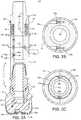
- Figure 3Aillustrates a cutting face of the drill bit 6.
- the drill bit 6may include a bit body 21, a shank 22, the cutting face, and a gage section.
- the shank 22may be tubular and include an upper piece and a lower piece connected to the upper piece, such as by threaded couplings secured by a weld.
- the bit body 21may be made from a composite material, such as a ceramic and/or cermet body powder infiltrated by a metallic binder.
- the bit body 21may be mounted to the lower shank piece during molding thereof.
- the shank 22may be made from a metal or alloy, such as steel, and have a coupling, such as a threaded pin, formed at an upper end thereof for connection of the drill bit 6 to the suspension sub 5.
- the shank 22may have a flow bore formed therethrough and the flow bore may extend into the bit body 21 to a plenum thereof.
- the cutting facemay form a lower end of the drill bit 6 and the gage section may form at an outer portion thereof.
- the bit body 21may be metallic, such as being made from steel, and may be hardfaced.
- the metallic bit bodymay be connected to a modified shank by threaded couplings and then secured by a weld.
- the cutting facemay include one or more (three shown) primary blades 23p, one or more (four shown) secondary blades 23s, fluid courses formed between the blades, leading cutters 24a, and backup cutters 24b.
- the blades 23p,smay be disposed around the cutting face and each blade may be formed during molding of the bit body 21 and may protrude from the bottom of the bit body.
- the primary blades 23pmay each extend from a center of the cutting face to the gage section.
- One or more ports 25may be formed in the bit body 21 and each port may extend from the plenum and through the bottom of the bit body to discharge drilling fluid 8 along the fluid courses.
- a nozzle(not shown) may be disposed in each port and fastened to the bit body 21.
- An inner set (not shown) of one or more of the ports 25may be disposed adjacent to the center of the cutting face.
- the secondary blades 14smay extend from a location on the cutting face adjacent to the inner set of ports 25 to the gage section.
- Each blade 23p,smay extend generally radially from the cutting face to the gage section with a slight spiral curvature.
- Each blade 23p,smay be made from the same material as the bit body 21.
- the leading cutters 24amay be mounted in pockets formed along leading edges of the blades 23p,s, such as by brazing.
- the backup cutters 24bmay be mounted in pockets formed along bottoms of the blades 23p,s, such as by brazing.
- Each backup cutter 24bmay be aligned or slightly offset from a respective leading cutter 24a.
- the backup cutters 24bmay or may not fully extend to the gage section.
- Each cutter 24a,bmay include a superhard cutting table, such as polycrystalline diamond, attached to a hard substrate, such as a cermet, thereby forming a compact, such as a polycrystalline diamond compact (PDC).
- a lower tip 26 of each blade 14p,smay impregnated with a superhard material, such as diamond, to enhance abrasion resistance.
- the gage sectionmay include a plurality of gage pads 27 and junk slots formed between the gage pads.
- the junk slotsmay be in fluid communication with the fluid courses formed between the blades 23p,s.
- the gage pads 27may be disposed around the gage section and each pad may be formed during molding of the bit body 12 and may protrude from the outer portion of the bit body.
- Each gage pad 27may be made from the same material as the bit body and each gage pad may be formed integrally with a respective blade 23p,s.
- FIG. 3Dillustrates one of the cutters 24a,b.
- Each cutter 24a,bmay be mounted, such as brazed, in the respective pocket at a back rake angle 28 ranging from thirty to forty-five degrees.
- Each cutter 24a,bmay have a chamfer formed in a edge of the cutting table.
- An angle 29 of each chamfermay range between thirty and sixty degrees and a height 30 of each chamfer may range between six-tenths of a millimeter and one and a half millimeters.
- the large back rake angle 28 and/or large chamfer height 30may improve the impact resistance of the cutters 24a,b to withstand drilling in the resonance mode. This improvement in impact resistance may come with some sacrifice of cutting efficiency.
- the back rake angle 28may range between zero and sixty degrees
- the chamfer angle 29may range between thirty and eighty degrees
- the chamfer height 30may range between one-tenth of a millimeter and three millimeters.
- Figures 3B and 3Cillustrate cutting faces of first 32 and second 33 alternative drill bits usable with the BHA 2, according to other embodiments of the present disclosure.
- Either the first alternative drill bit 32 or the second alternative drill bit 33may be connected to the suspension sub 5 instead of the drill bit 6.
- the first alternative drill bit 32may be similar to the drill bit 6 except for omission of two secondary blades 23s and omission of the backup cutters 24b.
- the drill bit 6may have the backup cutters 24b omitted therefrom.
- the first alternative drill bit 32may have the backup cutters 24b.
- the second alternative drill bit 33may be similar to the drill bit 6 except for addition of a primary blade 23p, the blades being more spiral, shock studs 33d being located on portions of the primary blades adjacent to the center of the cutting face and peripheral portions of the secondary blades 23s.
- Each shock stud 33dmay be made from a cermet and may or may not be impregnated with a superhard material, such as diamond, to enhance abrasion resistance.
- shock ringssuch as o-rings, may be used instead of the shock studs 33d.
- the drill bit 6 and/or the first alternative drill bit 32may have the shock studs 33d and/or the spiral blades.
- second alternative drill bit 33may have the secondary cutters omitted therefrom, may have the radial blades and/or may have the shock studs 33d omitted therefrom.
- a roller cone drill bit, hammer drill bit, or impregnated drill bitmay be connected to the suspension sub 5 instead of the fixed cutter drill bit 6.
- Figure 4illustrates tuning of the BHA 2.
- the forcing frequency of the drill bit 6, 32, 33may be determined.
- the forcing frequencymay be determined by multiplying the total (primary and secondary) number of blades by the angular velocity of the BHA 2 in revolutions per second. Either the desired angular velocity for drilling the soft formation 12s or the hard formation 12h may be used. For example, assuming that the drill bit 6 is selected and the BHA is to be rotated at sixty revolutions per minute (RPM) (one revolution per second) in the soft formation 12s, then the forcing frequency would be equal to seven Hertz (Hz). The forcing frequency may then be used to configure the Belleville washers 19 to exhibit a damping frequency at seven Hz (or resonant frequency if the angular velocity is desired instead for the hard formation 12h).
- RPMrevolutions per minute
- the parameters of the Belleville washers 19that may be varied to select a stack configuration exhibiting the damping frequency at the forcing frequency include: inner diameter 34n of each Belleville washer, outer diameter 34o of each Belleville washer, height 34h of each Belleville washer, thickness 34t of each Belleville washer, number of Belleville washers in the stack 19s, and whether the Belleville washers are stacked in series and/or parallel.
- the selection of the parametersmay be facilitated by dynamic modeling software executed on a computer.
- the resonant frequency of the stackmay be determined and used to determine the angular velocity of the BHA 2 to shift from the damping mode to the resonant mode (or vice versa, if the resonant frequency was used to configure the stack instead of the damping frequency).
- the diameters 34n,omay be fixed and the number in the stack 19s may be limited; however, the stack may be shorter than the height of the spring chamber and then shimmed to the height of the spring chamber.
- some parameters of the drill bit 6may be used to alter the dynamic response of the suspension sub 5.
- inclusion of the backup cutters 24bmay serve to flatten the peak of the resonant frequency and create a resonant frequency band versus omission thereof.
- Increasing spiraling of the blades 14p,smay also serve to flatten the peak of the resonant frequency and create a resonant frequency band versus radial blades.
- weight on bitmay be adjusted during drilling to adjust the stroke of the suspension sub in the resonant mode.
- Figure 5illustrates further drilling of the wellbore using the BHA 2.
- a rate of penetrationmay decrease as the drill bit 6 drills through the hard formation 12h.
- the suspension submay be shifted back to the damping mode for drilling through a second soft formation 35a by increasing rotation back to the first angular velocity 7d.
- the suspension sub 5may be shifted back to the resonant mode for drilling through a second hard formation 35b by decreasing rotation back to the second angular velocity 7r.
- the suspension sub 5may be shifted back to the damping mode for drilling through a third soft formation 35c by increasing rotation back to the first angular velocity 7d.
- the suspension sub 5may be shifted back to the resonant mode for drilling through a third hard formation 35d by decreasing rotation back to the second angular velocity 7r.
- the suspension sub 5may be shifted back to the damping mode for drilling through a fourth soft formation 35e by increasing rotation back to the first angular velocity 7d.
- a prior art solution to drilling the wellboreinvolves drilling the soft formations 12s, 35a,c,e with a PDC drill bit and drilling the hard formations 7h, 35b,d with a roller cone drill bit. This means that each time a different formation is encountered, the drill string must be retrieved to a drilling rig at surface, the drill bit changed, and the drill string re-deployed into the wellbore (aka a round trip), thereby resulting in six additional round trips to finish drilling the wellbore.
- the BHA 2While the BHA 2 will likely not achieve the ROP of either the PDC drill bit drilling through the soft formations or the roller cone drill bit drilling through the hard formations, the BHA is capable of drilling the entire wellbore without the additional six round trips to swap the drill bits which will result in much less rig deployment time to drill the wellbore 1.
- FIGS 6A and 6Billustrate a first alternative suspension sub 36 usable with the BHA 2, according to another embodiment of the present disclosure.
- the first alternative suspension sub 36may be assembled as part of the BHA 2 instead of the suspension sub 5.
- the first alternative suspension sub 36may be similar to the suspension sub 5 except for including an inner stack 36n of Belleville washers 19 and an outer stack 36o of Belleville washers disposed in the spring chamber.
- the outer stack 36omay be concentrically disposed about the inner stack 36n.
- the outer stack 36omay have at least one parameter different from the inner stack 36n, such as the outer stack having a different number of Belleville washers (eight versus six as shown).
- the first alternative suspension sub 36 having two stacks 36n,omay add an additional set of resonant and damping frequencies (see Figure 6E ) to the dynamic response, thereby allowing more flexibility in tuning.
- the inner stack 36n and/or the outer stack 36omay include only one Belleville washer 19.
- FIGs 6C and 6Dillustrate a second alternative suspension sub 37 usable with the BHA 2, according to another embodiment of the present disclosure.
- Figure 6Eillustrates a dynamic response of the second alternative suspension sub 37.
- the second alternative suspension sub 37may be assembled as part of the BHA 2 instead of the suspension sub 5.
- the second alternative suspension sub 37may be similar to the suspension sub 5 except for including a plurality 37a-c of stacks of Belleville washers 19 disposed in the spring chamber and a guide rod 37r for each stack.
- Each guide rod 37rmay be connected to the stator, extend through the spring chamber and be received in a guide passage formed in the traveler.
- the stacks 37a-cmay be eccentrically disposed about the spring chamber and each stack may be disposed around a respective guide rod 37r.
- Each stack 37a-cmay have at least one parameter different from the other stacks, such as the first stack 37a having five Belleville washers 19 arranged in series, the second stack 37b having seven Belleville washers arranged in series and parallel, and a third stack 37c having three Belleville washers arranged in series.
- the second alternative suspension sub 37 having three stacks 37a-cmay add two additional sets of resonant and damping frequencies to the dynamic response, thereby allowing more flexibility in tuning.
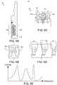
- FIG. 7Aillustrates a third alternative suspension sub 38 usable with the BHA 2, according to another embodiment of the present disclosure.
- Figure 7Billustrates a dynamic response of the third alternative suspension sub 38.
- the third alternative suspension sub 38may be assembled as part of the BHA 2 instead of the suspension sub 5.
- the third alternative suspension sub 38may include a modified stator 44, the traveler 15, the outer sleeve 16 (not shown), the slip joint 17 (not shown), the torsional joint(s) 18 (not shown), a spring 39, a variable damper 40, and sliding seals (not shown) sealing the interfaces between the modified stator and the traveler and between the outer sleeve and the traveler.
- the spring 39may be another type besides a Belleville washer, such as any other type of compression spring or any type of tension spring, such as a coil spring, gas spring, or wave spring.
- the modified stator 44may be similar to the stator 14 except for having a balanced hydraulic fluid reservoir (not shown) disposed in the head (not shown) thereof and hydraulic passages formed therein and extending between the reservoir and the spring chamber.
- the spring 39may be disposed in the spring chamber and hydraulic fluid, such as refined and/or synthetic oil, may be disposed in the spring chamber and the reservoir.
- the variable damper 40may include a dashpot 41, a bypass valve 42, a battery 43, and an electronics package 45.
- the electronics package 45may include one or more circuits integrated on a printed circuit board (not shown), such as a tachometer 45t, a memory unit 45m, a microcontroller 45c, and an actuator 45a.
- the modified stator 44may also have an electronics chamber (not shown) formed therein for housing the electronics package 45 and the battery 43.
- the battery 43may be in electrical communication with the electronics package 45.
- the tachometer 45tmay be operable to measure the angular velocity of the BHA 2 and report the measurement to the microcontroller 45c.
- the memory unit 45mmay be preprogrammed with a resonant angular velocity band 46r and a damping angular velocity band 46d.
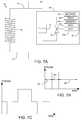
- the dashpot 41may be a fixed choke disposed in a first one of the hydraulic passages and the bypass valve 42 may be disposed in a second one of the hydraulic passages.
- the bypass valve 42may be a shutoff valve operable between an open position and a closed position.
- the open positionmay provide unrestricted fluid communication between the reservoir and the spring chamber, thereby bypassing the dashpot 41, and the closed position may block fluid flow along the second passage, thereby forcing fluid flow along only the first passage through the dashpot.
- the actuator 45amay be a linear or rotary electric actuator operable to move the bypass valve 42 between the positions.
- the microcontroller 45cmay monitor the angular velocity measurement from the tachometer 45t and compare the measurement to the frequency bands 46d,r stored in the memory unit 45m and the current mode that the variable damper 40 is in (active or bypassed).
- the active modemay place the third alternative suspension sub 38 in the damping mode and the bypassed mode may place the third alternative suspension sub in the resonant mode. If the variable damper 40 is in the correct mode, the microcontroller 45c may take no action. If the variable damper is not in the correct mode, then the microcontroller may operate the actuator 45a to open or close the bypass valve 42 to shift the variable damper 40 to the correct mode.
- the spring 39may be a stack of two or more springs (same or different type) in series.
- third alternative suspension sub 38may include a second spring or stack of springs in parallel with the spring 39, either concentrically or eccentrically arranged.
- the spring 39may be one or more Belleville washers.
- the variable damper 40may be disposed in a series arrangement with the spring 39.
- the modified stator 44may include a third hydraulic passage with a check valve oriented to allow unrestricted fluid flow from the reservoir to the spring chamber and prevent reverse flow therethrough.
- Figure 7Cillustrates a dynamic response of a modified third alternative suspension sub.
- the modified third alternative suspension submay be similar to the third alternative suspension sub 38 except for the dashpot 41 being a variable choke valve instead of a fixed choke, thereby providing for more control over the dynamic response of the modified third alternative suspension sub.
- the electronics packagemay include a second actuator for operating the variable choke valve.
- opening of the bypass valve 42may exhibit a full resonant mode having a full stroke amplitude at a first frequency band
- closing of the bypass valve and actuation of the variable choke valve to a relaxed settingmay exhibit a partial resonant mode having a partial amplitude (relative to full stroke) at a second frequency band
- closing of the bypass valve and actuation of the variable choke valve to a constricted settingmay exhibit the damping mode.
Landscapes
- Engineering & Computer Science (AREA)
- Geology (AREA)
- Life Sciences & Earth Sciences (AREA)
- Mining & Mineral Resources (AREA)
- Physics & Mathematics (AREA)
- Environmental & Geological Engineering (AREA)
- Fluid Mechanics (AREA)
- General Life Sciences & Earth Sciences (AREA)
- Geochemistry & Mineralogy (AREA)
- Mechanical Engineering (AREA)
- General Engineering & Computer Science (AREA)
- Acoustics & Sound (AREA)
- Aviation & Aerospace Engineering (AREA)
- Earth Drilling (AREA)
Description
- The present disclosure generally relates to a passively induced forced vibration rock drilling system.
U.S. Pat. No. 7,591,327 discloses a method for drilling a bore hole including the steps of deploying a drill bit attached to a drill string in a well bore, the drill bit having an axial jack element with a distal end protruding beyond a working face of the drill bit; engaging the distal end of the jack element against the formation such that the formation applies a reaction force on the jack element while the drill string rotates; and applying a force on the jack element that opposes the reaction force such that the jack element vibrates and imposes a resonant frequency into the formation.U.S. Pat. No. 9,033,069 U.S. Pat. No. 9,068,400 U.S. Pat. No. 6,234,728 discloses a mounting attachment for a penetrating tool such as a drilling head on a machine with a machining shaft includes a support provided with means for coupling to a machine; a tool holder provided with means for fixing a tool; means for axially guiding the tool holder relative to the support; means for linking in rotation the tool holder and the support; and elastically deformable suspension means for suspending the tool holder from the support, the suspension means allowing axial translation and self-sustaining reciprocating or vibrating axial movements of the tool holder resulting from a controlled displacement of the support with respect to a workpiece.U.S. Pat. No. 7,654,344 discloses a torque converter for use in drilling with a rotating drill bit, the purpose of the torque converter being to absorb impacts and bring about an axial movement of the drill bit when the torque exceeds a predetermined value. For this purpose the torque converter is composed of two cylindrical string parts connected through the bearing elements. The string parts are connected to each other through helical elements in such a way that relative rotation of the two cylindrical string parts brings about axial movement, which unloads the drill bit.U.S. Pat. App. Pub. No. 2016/0053545 discloses a drilling system including a drill string extendable into a wellbore penetrating a subterranean formation. The subterranean formation exhibits a resonant frequency and a drill bit is coupled to a distal end of the drill string. A vibration sub is positioned within the drill string adjacent the drill bit for generating vibration stress waves at the drill bit, and the vibration stress waves exhibit a vibration frequency that approximates the resonant frequency.U.S. Pat. App. Pub. No. 2016/0053546 discloses a bottom-hole assembly including a drill string extendable within a wellbore and a drill bit positioned at a distal end of the drill string. A vibration sub is positioned in the drill string axially adjacent the drill bit and includes one or more vibratory devices that impart vibration to the drill bit.U.S. Pat. App. Pub. No. 2016/0053547 discloses a drill bit including a bit body and one or more cutters positioned on the bit body at select locations. At least one vibrational device is positioned on the bit body to impart vibration to the bit body and thereby mitigate stick-slip.U.S. Pat. App. Pub. No. 2012/0228029 discloses a method for reducing friction between interconnected outer and inner helical members of a downhole damper where the damper includes an outer damper body and an inner damper body, and where the outer and inner damper bodies are telescopically movable relative each other, the outer and inner damper bodies being biased in the extending direction, and where one of the outer and inner damper bodies are connected to a drill bit workable at a borehole face, and where the other of the outer and inner damper bodies is connected to a torque and force transmitting member, and where the outer and inner helical parts are arranged so as to retract the bit from the face when torque applied by the torque and force transmitting member exceeds a preset value, wherein the method includes letting a relative movement between the inner and outer body force lubricant to flow between the helical members.GB 2 439 177GB 2 439 178WO 2007/141550 discloses a drilling apparatus comprising a drill-bit capable of rotary and high frequency oscillatory loading; and control means for controlling applied rotational and/or oscillatory loading of the drill-bit.WO 2015/052301 discloses an apparatus for use in resonance enhanced drilling, the apparatus comprising a drilling module comprising a drill-bit, wherein the apparatus further comprises: a sensor for measuring one or more parameters relating to the interaction of the drill-bit and the material being drilled; and a sensor for measuring one or more motions of the drill-bit.WO 2015/167796 discloses rotary percussive device, comprising a rotational translator having a rotational rotor and a rotational stator; and an axial translator having an axial stator, the axial translator being concentric with the rotational translator.U.S. Patent App. Pub. No. 4 276 947 discloses a double acting damper for use in rotary drilling includes a splined tubular telescopic joint and employs plural paralleled stacks of double acting series stacked roller Belleville spring washers in an annular pocket between the inner and outer tubular members of the joint.U.S. Patent App. Pub. No. 2007/221408 discloses a method for drilling a bore hole includes the steps of deploying a drill bit attached to a drill string in a well bore, the drill bit having an axial jack element with a distal end protruding beyond a working face of the drill bit; engaging the distal end of the jack element against the formation such that the formation applies a reaction force on the jack element while the drill string rotates; and applying a force on the jack element that opposes the reaction force such that the jack element vibrates and imposes a resonant frequency into the formation.- The present disclosure generally relates to a passively induced forced vibration rock drilling system. In one embodiment, a bottomhole assembly (BHA) includes: a drill bit operable to vibrate when engaged with a formation and rotated; and a suspension sub. The suspension sub includes: a stator barrel for connection to a pipe string; a traveler barrel for connection to the drill bit; a slip joint longitudinally coupling the traveler barrel to the stator barrel while allowing movement of the traveler barrel between an extended position and a retracted position; a torsional joint connecting the traveler barrel to the stator barrel at and between the positions; and one or more springs disposed between the stator barrel and the traveler barrel. The suspension sub is tuned relative to the drill bit to: dampen the vibration of the drill bit when the BHA is rotated at a first angular velocity; and resonate the vibration of the drill bit when the BHA is rotated at a second angular velocity, thereby imparting percussive energy to the drill bit.
- So that the manner in which the above recited features of the present disclosure can be understood in detail, a more particular description of the disclosure, briefly summarized above, may be had by reference to embodiments, some of which are illustrated in the appended drawings. It is to be noted, however, that the appended drawings illustrate only typical embodiments of this disclosure and are therefore not to be considered limiting of its scope, for the disclosure may admit to other equally effective embodiments.
Figure 1A illustrates drilling of a wellbore with a passively induced forced vibration bottomhole assembly (BHA) in a damping mode, according to one embodiment of the present disclosure.Figure 1B illustrates drilling of the wellbore with the BHA in a resonant mode.Figure 1C illustrates a dynamic response of the BHA.Figures 2A-2C illustrate the BHA.Figure 3A illustrates a cutting face of a drill bit of the BHA.Figures 3B and 3C illustrate cutting faces of first and second alternative drill bits usable with the BHA, according to other embodiments of the present disclosure.Figure 3D illustrates a cutter of the drill bit.Figure 4 illustrates tuning of the BHA.Figure 5 illustrates further drilling of the wellbore using the BHA.Figures 6A and 6B illustrate a first alternative suspension sub usable with the BHA, according to another embodiment of the present disclosure.Figures 6C and 6D illustrate a second alternative suspension sub usable with the BHA, according to another embodiment of the present disclosure.Figure 6E illustrates a dynamic response of the second alternative suspension sub.Figure 7A illustrates a third alternative suspension sub usable with the BHA, according to another embodiment of the present disclosure.Figure 7B illustrates a dynamic response of the third alternative suspension sub.Figure 7C illustrates a dynamic response of a modified third alternative suspension sub.Figure 1A illustrates drilling of awellbore 1 with a passively induced forced vibration bottomhole assembly (BHA) 2 in a damping mode.Figure 1B illustrates drilling of thewellbore 1 with theBHA 2 in a resonant mode.Figure 1C illustrates a dynamic response of theBHA 2. TheBHA 2 may be connected to a bottom of apipe string 3, such as drill pipe or coiled tubing, thereby forming a drill string, and deployed into thewellbore 1. TheBHA 2 may include one or more drill collars 4, asuspension sub 5, and a fixedcutter drill bit 6. Thedrill bit 6 may be rotated at a firstangular velocity 7d, such as by rotation of the drill string from a rig (not shown) and/or by a drilling motor (not shown) of theBHA 2, while drillingfluid 8, such as mud, may be pumped down the drill string. Some of the weight of the drill string may be set on thedrill bit 6 until the suspension sub is in a ready position (shown) between an extended position (not shown) and a retracted position (not shown). Thedrilling fluid 8 may be discharged by thedrill bit 6 and carry cuttings up an annulus 9 formed between the drill string and thewellbore 1 and/or between the drill string and a casing string and/orliner string 10. The drilling fluid and cuttings are collectively referred to as returns 11.- The
BHA 2 may be in the damping mode due to rotation thereof at the firstangular velocity 7d. The damping mode may be selected when thewellbore 1 is being drilled through asoft formation 12s. In the damping mode, thesuspension sub 5 may attenuate vibration of thedrill bit 6 due to engagement with thesoft formation 12s. This attenuation allows the fixedcutter drill bit 6 to operate in a shearing mode which is an efficient manner of cutting the rock due to the soft formation exhibiting ductile failure. - However, once a
hard rock formation 12h is encountered, the shearing mode becomes inefficient. Once thehard rock formation 12h is encountered, the rotation of theBHA 2 may be reduced to a secondangular velocity 7r, thereby shifting the BHA to a resonant mode. In the resonant mode, thesuspension sub 5 may reciprocate 13 thedrill bit 6 in response to the vibration thereof, thereby shifting operation of the drill bit to the percussive mode which is an efficient manner of cutting the rock due to thehard formation 12h exhibiting brittle failure. - Advantageously, the
BHA 2 is a passive device that operates utilizing inherent vibration of thedrill bit 6 created by operation thereof without using a resonator tool which requires an energy source. - Alternatively, the angular velocity may be increased instead of being reduced to shift the
BHA 2 from the damping mode to the resonant mode. Figures 2A-2C illustrate theBHA 2. Thesuspension sub 5 may include astator 14, atraveler 15, anouter sleeve 16, a slip joint 17, one or more (pair shown)torsional joints 18, and one or more (eight shown) compression springs, such asBelleville washers 19. Thesuspension sub 5 may have a longitudinal bore therethrough for passage of thedrilling fluid 8. Thestator 14 may be an upper barrel and thetraveler 15 may be a lower barrel. To facilitate assembly, thetraveler 15 may include a pair ofsemi-cylindrical segments 15a,b connected together, such as by threadedfasteners 20a,b. Thestator 14 may have a coupling, such as a threaded pin, formed at an upper end thereof for connection of the drill collar 4 to thesuspension sub 5. Thetraveler 15 may have a coupling, such as a threaded box, formed at a lower end thereof for connection of thesuspension sub 5 to thedrill bit 6.- The slip joint 17 may allow the
traveler 15 to longitudinally move relative to thestator 14 between an extended position (not shown) and a retracted position (not shown). Thestator 14 may have anupper head 14h and alower stem 14s having a reduced outer diameter relative to the head. Aspring shoulder 14d may be formed between thehead 14h and stem 14s portions of thestator 14. Thetraveler 15 may receive thestem 14s therein and a sliding fit may be formed between an outer surface of the stem and an inner surface of the traveler. Thestator 14, thetraveler 15, and thesleeve 16 may each be made from a metal or alloy, such as steel, stainless steel, or a nickel based alloy, having strength sufficient to support the weight and torque exerted on thedrill bit 6 during drilling. - The slip joint 17 may include a
stop ring 17r, astop groove 17g, a retaininggroove 17v, and one or more threadedfasteners 20c,d. To facilitate assembly, thestop ring 17r may include a pair ofsemi-arcuate segments 17a,b connected together, such as by the threadedfasteners 20c,d. The retaininggroove 17v may be formed in an outer surface of thestem 14s and the stop ring may 17r may be assembled in the retaining groove, thereby longitudinally connecting the stop ring to thestator 14. Thestop groove 17g may be formed in the inner surface of thetraveler 15 and the traveler may be assembled such that the stop groove receives thestop ring 17r therein. Thestop groove 17g may have a length greater than a length of thestop ring 17r, thereby allowing limited longitudinal movement of thetraveler 15 relative to thestator 14. A differential between the length of thestop groove 17g and the length of thestop ring 17r may range between one-tenth of a millimeter and fifty millimeters. Thestop ring 17r may be engaged with an upper end of thestop groove 17g when thesuspension sub 5 is in the extended position and stop ring may be engaged with a lower end of the stop groove when the suspension sub is in the retracted position. - Each torsional joint 18 may include a key 18k, a retaining
slot 18r, aguide slot 18g, and a threadedfastener 20e. Each retainingslot 18r may be formed in an outer surface of thestem 14s and the respective key 18k may be fastened to the stem in the retaining slot, thereby longitudinally and torsionally connecting the key to thestator 14. Eachguide slot 18g may be formed in the inner surface of thetraveler 15 and the traveler may be assembled such that the guide slot receives the respective key 18k therein. Eachguide slot 18g may have a length greater than a length of the respective key 18k, thereby allowing limited longitudinal movement of thetraveler 15 relative to thestator 14 while torsionally connecting the traveler to the stator such that the traveler rotates with the stator during drilling. A differential between the length of eachguide slot 18g and the length of the respective key 18k may be greater than the differential between the length of thestop groove 17g and the length of thestop ring 17r. - A spring chamber may be formed longitudinally between the
spring shoulder 14d and a top of thetraveler 15. The spring chamber may be formed radially between an inner surface of thesleeve 16 and an outer surface of thestem 14s. The Belleville washers 19 may be disposed in the spring chamber and stacked 19s in a series (shown) arrangement and/or a parallel (Figure 4 ) arrangement. The Belleville washers 19 may bias thesuspension sub 5 toward the extended position. In the resonate mode, theBelleville washers 19 may store energy from the upward vibration of thedrill bit 6 and expel the energy during downward vibration of the drill bit, thereby causing thestop ring 17r to strike the lower end of the stop groove and imparting percussive energy to thedrill bit 6. In the damping mode, theBelleville washers 19 may attenuate the vibration of thedrill bit 6 via friction between the individual washers. - An upper end of the
sleeve 16 may be received in a recess formed in the outer surface of thehead 14h and the sleeve may be longitudinally and torsionally connected to thestator 14, such as by thefastener 20f. Thesleeve 16 may extend downward to cover the spring chamber and overlap an outer surface of thetraveler 15. A sliding fit may be formed between an outer surface of thetraveler 15 and an inner surface of thesleeve 16. Thesleeve 16 may prevent the cuttings in thereturns 11 from entering the spring chamber and obstructing operation of theBelleville washers 19. - Alternatively, a sliding seal may be carried by the
stem 14s and may be engaged with a polished receptacle formed in an inner surface of thetraveler 15, another sliding seal may be carried by thesleeve 16 and may be engaged with a polished outer surface of thetraveler 15, lubricant may be disposed in the spring chamber, and a balanced lubricant reservoir may be formed in thehead 14h. Figure 3A illustrates a cutting face of thedrill bit 6. Referring also toFigure 2A , thedrill bit 6 may include abit body 21, ashank 22, the cutting face, and a gage section. Theshank 22 may be tubular and include an upper piece and a lower piece connected to the upper piece, such as by threaded couplings secured by a weld. Thebit body 21 may be made from a composite material, such as a ceramic and/or cermet body powder infiltrated by a metallic binder. Thebit body 21 may be mounted to the lower shank piece during molding thereof. Theshank 22 may be made from a metal or alloy, such as steel, and have a coupling, such as a threaded pin, formed at an upper end thereof for connection of thedrill bit 6 to thesuspension sub 5. Theshank 22 may have a flow bore formed therethrough and the flow bore may extend into thebit body 21 to a plenum thereof. The cutting face may form a lower end of thedrill bit 6 and the gage section may form at an outer portion thereof.- Alternatively, the
bit body 21 may be metallic, such as being made from steel, and may be hardfaced. The metallic bit body may be connected to a modified shank by threaded couplings and then secured by a weld. - The cutting face may include one or more (three shown)
primary blades 23p, one or more (four shown)secondary blades 23s, fluid courses formed between the blades, leadingcutters 24a, andbackup cutters 24b. Theblades 23p,s may be disposed around the cutting face and each blade may be formed during molding of thebit body 21 and may protrude from the bottom of the bit body. Theprimary blades 23p may each extend from a center of the cutting face to the gage section. One ormore ports 25 may be formed in thebit body 21 and each port may extend from the plenum and through the bottom of the bit body to dischargedrilling fluid 8 along the fluid courses. A nozzle (not shown) may be disposed in each port and fastened to thebit body 21. An inner set (not shown) of one or more of theports 25 may be disposed adjacent to the center of the cutting face. Thesecondary blades 14s may extend from a location on the cutting face adjacent to the inner set ofports 25 to the gage section. Eachblade 23p,s may extend generally radially from the cutting face to the gage section with a slight spiral curvature. - Each
blade 23p,s may be made from the same material as thebit body 21. The leadingcutters 24a may be mounted in pockets formed along leading edges of theblades 23p,s, such as by brazing. Thebackup cutters 24b may be mounted in pockets formed along bottoms of theblades 23p,s, such as by brazing. Eachbackup cutter 24b may be aligned or slightly offset from a respectiveleading cutter 24a. Thebackup cutters 24b may or may not fully extend to the gage section. Eachcutter 24a,b may include a superhard cutting table, such as polycrystalline diamond, attached to a hard substrate, such as a cermet, thereby forming a compact, such as a polycrystalline diamond compact (PDC). Alower tip 26 of each blade 14p,s may impregnated with a superhard material, such as diamond, to enhance abrasion resistance. - The gage section may include a plurality of
gage pads 27 and junk slots formed between the gage pads. The junk slots may be in fluid communication with the fluid courses formed between theblades 23p,s. Thegage pads 27 may be disposed around the gage section and each pad may be formed during molding of the bit body 12 and may protrude from the outer portion of the bit body. Eachgage pad 27 may be made from the same material as the bit body and each gage pad may be formed integrally with arespective blade 23p,s. Figure 3D illustrates one of thecutters 24a,b. Eachcutter 24a,b may be mounted, such as brazed, in the respective pocket at aback rake angle 28 ranging from thirty to forty-five degrees. Eachcutter 24a,b may have a chamfer formed in a edge of the cutting table. Anangle 29 of each chamfer may range between thirty and sixty degrees and aheight 30 of each chamfer may range between six-tenths of a millimeter and one and a half millimeters. The largeback rake angle 28 and/orlarge chamfer height 30 may improve the impact resistance of thecutters 24a,b to withstand drilling in the resonance mode. This improvement in impact resistance may come with some sacrifice of cutting efficiency.- Alternatively, the
back rake angle 28 may range between zero and sixty degrees, thechamfer angle 29 may range between thirty and eighty degrees, and/or thechamfer height 30 may range between one-tenth of a millimeter and three millimeters. Figures 3B and 3C illustrate cutting faces of first 32 and second 33 alternative drill bits usable with theBHA 2, according to other embodiments of the present disclosure. Either the firstalternative drill bit 32 or the secondalternative drill bit 33 may be connected to thesuspension sub 5 instead of thedrill bit 6. The firstalternative drill bit 32 may be similar to thedrill bit 6 except for omission of twosecondary blades 23s and omission of thebackup cutters 24b.- Alternatively, the
drill bit 6 may have thebackup cutters 24b omitted therefrom. Alternatively, the firstalternative drill bit 32 may have thebackup cutters 24b. - The second
alternative drill bit 33 may be similar to thedrill bit 6 except for addition of aprimary blade 23p, the blades being more spiral,shock studs 33d being located on portions of the primary blades adjacent to the center of the cutting face and peripheral portions of thesecondary blades 23s. Eachshock stud 33d may be made from a cermet and may or may not be impregnated with a superhard material, such as diamond, to enhance abrasion resistance. - Alternatively, shock rings, such as o-rings, may be used instead of the
shock studs 33d. Alternatively, thedrill bit 6 and/or the firstalternative drill bit 32 may have theshock studs 33d and/or the spiral blades. Alternatively, secondalternative drill bit 33 may have the secondary cutters omitted therefrom, may have the radial blades and/or may have theshock studs 33d omitted therefrom. - Alternatively, a roller cone drill bit, hammer drill bit, or impregnated drill bit may be connected to the
suspension sub 5 instead of the fixedcutter drill bit 6. Figure 4 illustrates tuning of theBHA 2. In order to tune thesuspension sub 5, the forcing frequency of thedrill bit BHA 2 in revolutions per second. Either the desired angular velocity for drilling thesoft formation 12s or thehard formation 12h may be used. For example, assuming that thedrill bit 6 is selected and the BHA is to be rotated at sixty revolutions per minute (RPM) (one revolution per second) in thesoft formation 12s, then the forcing frequency would be equal to seven Hertz (Hz). The forcing frequency may then be used to configure theBelleville washers 19 to exhibit a damping frequency at seven Hz (or resonant frequency if the angular velocity is desired instead for thehard formation 12h).- The parameters of the
Belleville washers 19 that may be varied to select a stack configuration exhibiting the damping frequency at the forcing frequency include:inner diameter 34n of each Belleville washer, outer diameter 34o of each Belleville washer,height 34h of each Belleville washer,thickness 34t of each Belleville washer, number of Belleville washers in thestack 19s, and whether the Belleville washers are stacked in series and/or parallel. The selection of the parameters may be facilitated by dynamic modeling software executed on a computer. - Once the configuration of the
stack 19s ofBelleville washers 19 has been determined, then the resonant frequency of the stack may be determined and used to determine the angular velocity of theBHA 2 to shift from the damping mode to the resonant mode (or vice versa, if the resonant frequency was used to configure the stack instead of the damping frequency). - If the
suspension sub 5 has already been designed and/or manufactured, then thediameters 34n,o may be fixed and the number in thestack 19s may be limited; however, the stack may be shorter than the height of the spring chamber and then shimmed to the height of the spring chamber. - Further, some parameters of the
drill bit 6 may be used to alter the dynamic response of thesuspension sub 5. For example, inclusion of thebackup cutters 24b may serve to flatten the peak of the resonant frequency and create a resonant frequency band versus omission thereof. Increasing spiraling of the blades 14p,s may also serve to flatten the peak of the resonant frequency and create a resonant frequency band versus radial blades. Further, weight on bit may be adjusted during drilling to adjust the stroke of the suspension sub in the resonant mode. Figure 5 illustrates further drilling of the wellbore using theBHA 2. A rate of penetration (ROP) may decrease as thedrill bit 6 drills through thehard formation 12h. Once thehard formation 12h has been drilled through with thesuspension sub 5 in the resonant mode, the suspension sub may be shifted back to the damping mode for drilling through a secondsoft formation 35a by increasing rotation back to the firstangular velocity 7d. Once the secondsoft formation 35a has been drilled through, thesuspension sub 5 may be shifted back to the resonant mode for drilling through a secondhard formation 35b by decreasing rotation back to the secondangular velocity 7r. Once the secondhard formation 35b has been drilled through, thesuspension sub 5 may be shifted back to the damping mode for drilling through a thirdsoft formation 35c by increasing rotation back to the firstangular velocity 7d. Once the thirdsoft formation 35c has been drilled through, thesuspension sub 5 may be shifted back to the resonant mode for drilling through a thirdhard formation 35d by decreasing rotation back to the secondangular velocity 7r. Once the thirdhard formation 35d has been drilled through, thesuspension sub 5 may be shifted back to the damping mode for drilling through a fourthsoft formation 35e by increasing rotation back to the firstangular velocity 7d.- A prior art solution to drilling the wellbore involves drilling the
soft formations hard formations 7h, 35b,d with a roller cone drill bit. This means that each time a different formation is encountered, the drill string must be retrieved to a drilling rig at surface, the drill bit changed, and the drill string re-deployed into the wellbore (aka a round trip), thereby resulting in six additional round trips to finish drilling the wellbore. While theBHA 2 will likely not achieve the ROP of either the PDC drill bit drilling through the soft formations or the roller cone drill bit drilling through the hard formations, the BHA is capable of drilling the entire wellbore without the additional six round trips to swap the drill bits which will result in much less rig deployment time to drill thewellbore 1. Figures 6A and 6B illustrate a firstalternative suspension sub 36 usable with theBHA 2, according to another embodiment of the present disclosure. The firstalternative suspension sub 36 may be assembled as part of theBHA 2 instead of thesuspension sub 5. The firstalternative suspension sub 36 may be similar to thesuspension sub 5 except for including aninner stack 36n ofBelleville washers 19 and an outer stack 36o of Belleville washers disposed in the spring chamber. The outer stack 36o may be concentrically disposed about theinner stack 36n. The outer stack 36o may have at least one parameter different from theinner stack 36n, such as the outer stack having a different number of Belleville washers (eight versus six as shown). The firstalternative suspension sub 36 having twostacks 36n,o may add an additional set of resonant and damping frequencies (seeFigure 6E ) to the dynamic response, thereby allowing more flexibility in tuning.- In the circuit diagrams of
Figures 6B and 6D , theBelleville washers 36n,o, 37a-c are depicted by both a spring element and a damping element due to the complex dynamic response thereof. - Alternatively, the
inner stack 36n and/or the outer stack 36o may include only oneBelleville washer 19. Figures 6C and 6D illustrate a secondalternative suspension sub 37 usable with theBHA 2, according to another embodiment of the present disclosure.Figure 6E illustrates a dynamic response of the secondalternative suspension sub 37. The secondalternative suspension sub 37 may be assembled as part of theBHA 2 instead of thesuspension sub 5. The secondalternative suspension sub 37 may be similar to thesuspension sub 5 except for including aplurality 37a-c of stacks ofBelleville washers 19 disposed in the spring chamber and aguide rod 37r for each stack. Eachguide rod 37r may be connected to the stator, extend through the spring chamber and be received in a guide passage formed in the traveler. Thestacks 37a-c may be eccentrically disposed about the spring chamber and each stack may be disposed around arespective guide rod 37r. Eachstack 37a-c may have at least one parameter different from the other stacks, such as thefirst stack 37a having fiveBelleville washers 19 arranged in series, thesecond stack 37b having seven Belleville washers arranged in series and parallel, and athird stack 37c having three Belleville washers arranged in series. The secondalternative suspension sub 37 having threestacks 37a-c may add two additional sets of resonant and damping frequencies to the dynamic response, thereby allowing more flexibility in tuning.Figure 7A illustrates a thirdalternative suspension sub 38 usable with theBHA 2, according to another embodiment of the present disclosure.Figure 7B illustrates a dynamic response of the thirdalternative suspension sub 38. The thirdalternative suspension sub 38 may be assembled as part of theBHA 2 instead of thesuspension sub 5. The thirdalternative suspension sub 38 may include a modifiedstator 44, thetraveler 15, the outer sleeve 16 (not shown), the slip joint 17 (not shown), the torsional joint(s) 18 (not shown), aspring 39, avariable damper 40, and sliding seals (not shown) sealing the interfaces between the modified stator and the traveler and between the outer sleeve and the traveler. Due to provision of thevariable damper 40, thespring 39 may be another type besides a Belleville washer, such as any other type of compression spring or any type of tension spring, such as a coil spring, gas spring, or wave spring.- The modified
stator 44 may be similar to thestator 14 except for having a balanced hydraulic fluid reservoir (not shown) disposed in the head (not shown) thereof and hydraulic passages formed therein and extending between the reservoir and the spring chamber. Thespring 39 may be disposed in the spring chamber and hydraulic fluid, such as refined and/or synthetic oil, may be disposed in the spring chamber and the reservoir. Thevariable damper 40 may include adashpot 41, abypass valve 42, abattery 43, and anelectronics package 45. Theelectronics package 45 may include one or more circuits integrated on a printed circuit board (not shown), such as atachometer 45t, amemory unit 45m, amicrocontroller 45c, and anactuator 45a. The modifiedstator 44 may also have an electronics chamber (not shown) formed therein for housing theelectronics package 45 and thebattery 43. Thebattery 43 may be in electrical communication with theelectronics package 45. - The
tachometer 45t may be operable to measure the angular velocity of theBHA 2 and report the measurement to themicrocontroller 45c. Thememory unit 45m may be preprogrammed with a resonantangular velocity band 46r and a dampingangular velocity band 46d. Thedashpot 41 may be a fixed choke disposed in a first one of the hydraulic passages and thebypass valve 42 may be disposed in a second one of the hydraulic passages. Thebypass valve 42 may be a shutoff valve operable between an open position and a closed position. The open position may provide unrestricted fluid communication between the reservoir and the spring chamber, thereby bypassing thedashpot 41, and the closed position may block fluid flow along the second passage, thereby forcing fluid flow along only the first passage through the dashpot. Theactuator 45a may be a linear or rotary electric actuator operable to move thebypass valve 42 between the positions. - In operation, the
microcontroller 45c may monitor the angular velocity measurement from thetachometer 45t and compare the measurement to thefrequency bands 46d,r stored in thememory unit 45m and the current mode that thevariable damper 40 is in (active or bypassed). The active mode may place the thirdalternative suspension sub 38 in the damping mode and the bypassed mode may place the third alternative suspension sub in the resonant mode. If thevariable damper 40 is in the correct mode, themicrocontroller 45c may take no action. If the variable damper is not in the correct mode, then the microcontroller may operate theactuator 45a to open or close thebypass valve 42 to shift thevariable damper 40 to the correct mode. - Alternatively, the
spring 39 may be a stack of two or more springs (same or different type) in series. Alternatively, thirdalternative suspension sub 38 may include a second spring or stack of springs in parallel with thespring 39, either concentrically or eccentrically arranged. Alternatively, thespring 39 may be one or more Belleville washers. Alternatively, thevariable damper 40 may be disposed in a series arrangement with thespring 39. Alternatively, the modifiedstator 44 may include a third hydraulic passage with a check valve oriented to allow unrestricted fluid flow from the reservoir to the spring chamber and prevent reverse flow therethrough. Figure 7C illustrates a dynamic response of a modified third alternative suspension sub. The modified third alternative suspension sub may be similar to the thirdalternative suspension sub 38 except for thedashpot 41 being a variable choke valve instead of a fixed choke, thereby providing for more control over the dynamic response of the modified third alternative suspension sub. The electronics package may include a second actuator for operating the variable choke valve. For example, opening of thebypass valve 42 may exhibit a full resonant mode having a full stroke amplitude at a first frequency band, closing of the bypass valve and actuation of the variable choke valve to a relaxed setting may exhibit a partial resonant mode having a partial amplitude (relative to full stroke) at a second frequency band, and closing of the bypass valve and actuation of the variable choke valve to a constricted setting may exhibit the damping mode.- While the foregoing is directed to embodiments of the present disclosure, other and further embodiments of the disclosure may be devised without departing from the basic scope thereof, and the scope of the invention is determined by the claims that follow.
Claims (12)
- A bottomhole assembly (BHA) (2), comprising:a drill bit (6) that will vibrate when engaged with a formation and rotated; anda suspension sub (5) comprising:a stator barrel (14) for connection to a pipe string (3);a traveler barrel (15) for connection to the drill bit (6);a slip joint (17) longitudinally coupling the traveler barrel (15) to the stator barrel (14) while allowing movement of the traveler barrel (15) between an extended position and a retracted position;a torsional joint (18) connecting the traveler barrel (15) to the stator barrel (14) at and between the positions; andone or more springs (39) disposed between the stator barrel (14) and the traveler barrel (15),characterized in that the suspension sub (5) is tuned relative to the drill bit (6) to:dampen the vibration of the drill bit (6) when the BHA (2) is rotated at a first angular velocity; andresonate the vibration of the drill bit (6) when the BHA (2) is rotated at a second angular velocity, thereby imparting percussive energy to the drill bit (6),wherein the suspension sub (5) further comprises a variable damper (40) operable to dampen the vibration of the drill bit (6);wherein the variable damper (40) comprises:a dashpot (41); andan electronics package comprising:an actuator (45a) operable to shift the variable damper between damping mode and resonant mode;a tachometer (45t) operable to measure angular velocity of the BHA (2);a memory unit (45m) operable to store the first and second angular velocities; anda microcontroller (45c) in communication with the tachometer (45t), the memory unit (45m), and the actuator (45a) and operable to activate the actuator (45a) in response to a comparison between the measured angular velocity and the first and second angular velocities.
- The BHA (2) of claim 1, wherein the one or more springs (39) are a stack of Belleville washers (19).
- The BHA (2) of claims 1 or 2, wherein the suspension sub (5) further comprises a second one or more springs (39) concentrically arranged with the one or more springs (39).
- The BHA (2) of claims 1 or 2, wherein the suspension sub (5) further comprises a second one or more springs (39) eccentrically arranged with the one or more springs (39).
- The BHA (2) of any preceding claim, wherein the drill bit (6) comprises:a shank (22) having a threaded coupling formed at an upper end thereof;a bit body (21) mounted to a lower end of the shank (22) and having a plenum;a gage section forming an outer portion of the drill bit (6); anda cutting face forming a lower end of the drill bit and comprising:a plurality of blades (23p,s) protruding from a bottom of the bit body (21) and extending from a center of the cutting face to the gage section; anda plurality of cutters (24a,b) mounted along each blade (23p,s).
- The BHA (2) of claim 5, wherein each cutter (24a,b) has a back rake angle ranging between zero and sixty degrees.
- The BHA (2) of claim 5, wherein:each cutter (24a,b) has a chamfer formed in an edge of a cutting table thereof, andeach chamfer has a height ranging between one-tenth of a millimeter and three millimeters.
- The BHA (2) of claim 1, wherein:the one or more springs (39) are disposed in a spring chamber formed between the stator barrel (14) and the traveler barrel (15), andthe suspension sub (5) further comprises:hydraulic fluid disposed in the spring chamber;a hydraulic reservoir; anda hydraulic passage extending between the spring chamber and the hydraulic reservoir, andthe dashpot (41) is disposed in the hydraulic passage.
- The BHA (2) of claim 8, wherein:the suspension sub (5) further comprises a second hydraulic passage extending between the spring chamber and the hydraulic reservoir, andthe variable damper (40) further comprises a bypass valve (42) disposed in the second hydraulic passage.
- The BHA (2) of claim 9, wherein:
the electronics package (45) further comprises:a battery (43); andthe actuator (45a) is operable to shift the bypass valve (42). - The BHA (2) of any preceding claim, wherein the dashpot (41) is either a fixed choke or a variable choke valve.
- A method of drilling a wellbore using the BHA (2) of any preceding claim, comprising:connecting the BHA (2) to a bottom of the pipe string (3), thereby forming a drill string;lowering the drill string into the wellbore (1) until the drill bit (6) is proximate a bottom thereof;exerting weight on the drill bit (6) to move the suspension sub (5) to a ready position between the extended position and the retracted position;characterized by;rotating the BHA (2) at the first angular velocity and injecting drilling fluid (8) through the drill string, thereby drilling through a soft formation (12s, 35a,c,e) with the suspension sub in the damping mode; andchanging the angular velocity to the second angular velocity in response to reaching a hard formation (12h, 35b,d), thereby drilling through the hard formation with the suspension sub in the resonant mode.
Priority Applications (5)
| Application Number | Priority Date | Filing Date | Title |
|---|---|---|---|
| EP16305713.6AEP3258056B1 (en) | 2016-06-13 | 2016-06-13 | Passively induced forced vibration rock drilling system |
| CA2966766ACA2966766A1 (en) | 2016-06-13 | 2017-05-10 | Passively induced forced vibration rock drilling system |
| US15/599,112US10378281B2 (en) | 2016-06-13 | 2017-05-18 | Passively induced forced vibration rock drilling system |
| RU2017120275ARU2738196C2 (en) | 2016-06-13 | 2017-06-09 | Rock drilling system with passive guidance of forced oscillations |
| CN201710441683.8ACN107489379B (en) | 2016-06-13 | 2017-06-13 | Passively induced forced vibration rock drilling system |
Applications Claiming Priority (1)
| Application Number | Priority Date | Filing Date | Title |
|---|---|---|---|
| EP16305713.6AEP3258056B1 (en) | 2016-06-13 | 2016-06-13 | Passively induced forced vibration rock drilling system |
Publications (2)
| Publication Number | Publication Date |
|---|---|
| EP3258056A1 EP3258056A1 (en) | 2017-12-20 |
| EP3258056B1true EP3258056B1 (en) | 2019-07-24 |
Family
ID=56263632
Family Applications (1)
| Application Number | Title | Priority Date | Filing Date |
|---|---|---|---|
| EP16305713.6AActiveEP3258056B1 (en) | 2016-06-13 | 2016-06-13 | Passively induced forced vibration rock drilling system |
Country Status (5)
| Country | Link |
|---|---|
| US (1) | US10378281B2 (en) |
| EP (1) | EP3258056B1 (en) |
| CN (1) | CN107489379B (en) |
| CA (1) | CA2966766A1 (en) |
| RU (1) | RU2738196C2 (en) |
Cited By (1)
| Publication number | Priority date | Publication date | Assignee | Title |
|---|---|---|---|---|
| WO2023138910A1 (en) | 2022-01-21 | 2023-07-27 | Stabilus Gmbh | Piston-cylinder unit, method for producing the piston-cylinder unit |
Families Citing this family (17)
| Publication number | Priority date | Publication date | Assignee | Title |
|---|---|---|---|---|
| US20180355668A1 (en)* | 2017-06-08 | 2018-12-13 | J & B Equipment Repair LLC | Vibrational drill head |
| GB201800250D0 (en)* | 2018-01-08 | 2018-02-21 | Element Six Gmbh | Drill bit with wearshield |
| CN110685612A (en)* | 2018-07-04 | 2020-01-14 | 陈玥丹 | Horizontal torsional elastic buffering and impact rock breaking drilling tool |
| CN109209239B (en)* | 2018-09-29 | 2023-09-01 | 吉林大学 | High-frequency rotary vibration type rock crushing drilling tool |
| EP3792448B1 (en)* | 2019-09-11 | 2022-11-02 | VAREL EUROPE (Société par Actions Simplifiée) | Drill bit with multiple cutting structures |
| WO2021050334A1 (en)* | 2019-09-12 | 2021-03-18 | Baker Hughes, A Ge Company, Llc | Bit support assembly incorporating damper for high frequency torsional oscillation |
| BR112022004718A2 (en)* | 2019-09-12 | 2022-06-14 | Baker Hughes Holdings Llc | Dampers for mitigating vibrations in downhole tool |
| CN110924871B (en)* | 2019-11-27 | 2024-09-24 | 王克行 | Drill bit, drill bit monitorable system and drill bit torque monitoring method |
| CN111021948B (en)* | 2019-12-30 | 2024-12-17 | 深圳市盛业地下工程有限公司 | Pile foundation combination equipment for rapid hole forming of complex geology |
| CN111236843A (en)* | 2020-03-06 | 2020-06-05 | 江苏和信石油机械有限公司 | Uniform driving type hydraulic oscillator for well drilling |
| CN111734402B (en)* | 2020-06-30 | 2023-03-24 | 中国石油天然气集团有限公司 | Logging-while-drilling electronic device bin |
| US11624246B2 (en)* | 2020-07-20 | 2023-04-11 | Baker Hughes Oilfield Operations Llc | Pass-through tapered nose tool |
| CN112324322B (en) | 2020-09-17 | 2024-08-06 | 广州市市政工程试验检测有限公司 | Rock and soil drilling method |
| CN113775295B (en)* | 2021-11-09 | 2022-01-18 | 西南石油大学 | Drill bit design method for tracking global equality of rock strength of rock breaking well bottom of drill bit |
| CN114876378B (en)* | 2022-04-30 | 2025-05-16 | 辽宁石油化工大学 | A stacked drill bit |
| WO2024031147A1 (en)* | 2022-08-11 | 2024-02-15 | Todd Haines | An accessory for a drill bit |
| CN117868686B (en)* | 2024-01-16 | 2024-06-14 | 中电建建筑集团有限公司 | Deviation correcting method of directional drill and filtering structure thereof |
Citations (2)
| Publication number | Priority date | Publication date | Assignee | Title |
|---|---|---|---|---|
| US3768576A (en)* | 1971-10-07 | 1973-10-30 | L Martini | Percussion drilling system |
| US4502552A (en)* | 1982-03-22 | 1985-03-05 | Martini Leo A | Vibratory rotary drilling tool |
Family Cites Families (29)
| Publication number | Priority date | Publication date | Assignee | Title |
|---|---|---|---|---|
| US2113651A (en)* | 1936-04-22 | 1938-04-12 | John W Heaston | Holder for rotary vibrating bits |
| US2628498A (en)* | 1948-05-06 | 1953-02-17 | Alonzo L Smith | Drilling rate indicating device |
| US3307641A (en)* | 1963-09-23 | 1967-03-07 | Exxon Production Research Co | Self-excited hammer drill |
| US4276947A (en)* | 1979-05-14 | 1981-07-07 | Smith International, Inc. | Roller Belleville spring damper |
| US5083623A (en)* | 1990-12-03 | 1992-01-28 | Halliburton Company | Hydraulic shock absorber |
| US5318138A (en) | 1992-10-23 | 1994-06-07 | Halliburton Company | Adjustable stabilizer |
| CN1096563A (en)* | 1993-09-29 | 1994-12-21 | 赵升吉 | Universal anti-skew shock-absorbing joint |
| US5803196A (en)* | 1996-05-31 | 1998-09-08 | Diamond Products International | Stabilizing drill bit |
| EP0870899A1 (en)* | 1997-04-11 | 1998-10-14 | Shell Internationale Researchmaatschappij B.V. | Drilling assembly with reduced stick-slip tendency |
| FR2765505B1 (en) | 1997-07-07 | 1999-08-27 | Inst Nat Polytech Grenoble | DRILLING HEAD WITH VIBRATORY EFFECT |
| NO322144B1 (en) | 2005-01-14 | 2006-08-21 | Tomax As | Torque converter for drilling with rotary drill bit |
| US7591327B2 (en)* | 2005-11-21 | 2009-09-22 | Hall David R | Drilling at a resonant frequency |
| GEP20135840B (en)* | 2006-06-09 | 2013-06-10 | Univ Aberdeen | Method and apparatus for drilling rock |
| NO325253B1 (en) | 2006-06-12 | 2008-03-10 | Tomax As | Device for a tool for axially displacing the drill bit in a drill string with varying torque |
| NO324265B1 (en) | 2006-06-12 | 2007-09-17 | Tomax As | Device for a tool for axially displacing the drill bit in a drill string with a liquid motor |
| EP2364397B2 (en)* | 2008-12-02 | 2025-06-04 | National Oilwell Varco, L.P. | Method and apparatus for reducing stick-slip |
| CN201486481U (en)* | 2009-08-04 | 2010-05-26 | 中国石化集团胜利石油管理局钻井工艺研究院 | PDC drill bit stick-slip vibration absorber |
| GB2473619B (en) | 2009-09-16 | 2012-03-07 | Iti Scotland Ltd | Resonance enhanced rotary drilling |
| WO2011084944A2 (en) | 2010-01-05 | 2011-07-14 | Smith International, Inc. | High-shear roller cone and pdc hybrid bit |
| MY164222A (en)* | 2010-07-01 | 2017-11-30 | Flexidrill Ltd | Radial vibrational apparatus |
| US20120228029A1 (en) | 2011-03-10 | 2012-09-13 | Tomax As | Method and Device for Reducing Friction Between Helical Members of a Downhole Damper |
| CN102140893B (en)* | 2011-04-11 | 2013-07-10 | 西南石油大学 | Magnetorheological intelligent drilling vibration damper |
| RU2014122863A (en) | 2012-06-13 | 2015-12-10 | Варел Интернэшнл Инд., Л.П. | POLYCRYSTALLINE DIAMOND CUTTERS FOR HIGHER STRENGTH AND HEAT RESISTANCE |
| GB201318020D0 (en)* | 2013-10-11 | 2013-11-27 | Iti Scotland Ltd | Drilling apparatus |
| US10364605B2 (en)* | 2014-04-28 | 2019-07-30 | Smith International, Inc. | Rotary percussive device |
| US10017997B2 (en) | 2014-08-25 | 2018-07-10 | Halliburton Energy Services, Inc. | Resonance-tuned drill string components |
| US9982487B2 (en) | 2014-08-25 | 2018-05-29 | Halliburton Energy Services, Inc. | Wellbore drilling systems with vibration subs |
| US10738537B2 (en) | 2014-08-25 | 2020-08-11 | Halliburton Energy Services, Inc. | Drill bits with stick-slip resistance |
| US10502006B2 (en) | 2015-09-18 | 2019-12-10 | Ulterra Drilling Technologies, L.P. | Rotary impact tool |
- 2016
- 2016-06-13EPEP16305713.6Apatent/EP3258056B1/enactiveActive
- 2017
- 2017-05-10CACA2966766Apatent/CA2966766A1/ennot_activeAbandoned
- 2017-05-18USUS15/599,112patent/US10378281B2/ennot_activeExpired - Fee Related
- 2017-06-09RURU2017120275Apatent/RU2738196C2/enactive
- 2017-06-13CNCN201710441683.8Apatent/CN107489379B/ennot_activeExpired - Fee Related
Patent Citations (2)
| Publication number | Priority date | Publication date | Assignee | Title |
|---|---|---|---|---|
| US3768576A (en)* | 1971-10-07 | 1973-10-30 | L Martini | Percussion drilling system |
| US4502552A (en)* | 1982-03-22 | 1985-03-05 | Martini Leo A | Vibratory rotary drilling tool |
Cited By (3)
| Publication number | Priority date | Publication date | Assignee | Title |
|---|---|---|---|---|
| WO2023138910A1 (en) | 2022-01-21 | 2023-07-27 | Stabilus Gmbh | Piston-cylinder unit, method for producing the piston-cylinder unit |
| DE102022101447A1 (en) | 2022-01-21 | 2023-07-27 | Stabilus Gmbh | Piston-cylinder unit, method for manufacturing the piston-cylinder unit |
| DE102022101447B4 (en) | 2022-01-21 | 2024-04-18 | Stabilus Gmbh | Piston-cylinder unit, method for producing the piston-cylinder unit |
Also Published As
| Publication number | Publication date |
|---|---|
| RU2017120275A (en) | 2018-12-10 |
| RU2017120275A3 (en) | 2020-06-17 |
| CN107489379B (en) | 2021-04-20 |
| EP3258056A1 (en) | 2017-12-20 |
| US10378281B2 (en) | 2019-08-13 |
| CA2966766A1 (en) | 2017-12-13 |
| US20170356249A1 (en) | 2017-12-14 |
| CN107489379A (en) | 2017-12-19 |
| RU2738196C2 (en) | 2020-12-09 |
Similar Documents
| Publication | Publication Date | Title |
|---|---|---|
| EP3258056B1 (en) | Passively induced forced vibration rock drilling system | |
| US10995556B2 (en) | Drill bits with stick-slip resistance | |
| EP3390760B1 (en) | Self-adjusting earth-boring tools and related systems and methods | |
| US8201642B2 (en) | Drilling assemblies including one of a counter rotating drill bit and a counter rotating reamer, methods of drilling, and methods of forming drilling assemblies | |
| EP2198114B1 (en) | A downhole device | |
| US7484576B2 (en) | Jack element in communication with an electric motor and or generator | |
| US11448015B2 (en) | Dampers for mitigation of downhole tool vibrations | |
| CN112088240B (en) | Damper for damping vibration of downhole tools and vibration isolation apparatus for downhole bottom hole assembly | |
| US20150176344A1 (en) | Downhole assembly | |
| CN108368728A (en) | Impact including can passively adjust changes the earth-boring tools and correlation technique of component | |
| US20170074047A1 (en) | Actively controlled self-adjusting bits and related systems and methods | |
| US20160053546A1 (en) | Wellbore drilling systems with vibration subs | |
| EP4028628A1 (en) | Dampers for mitigation of downhole tool vibrations | |
| WO2023287639A1 (en) | Shock-based damping systems and mechanisms for vibration damping in downhole applications | |
| EP3667012A1 (en) | Self adjusting earth boring tools and related systems and methods of reducing vibrations | |
| WO2025080860A1 (en) | Self-tuning friction damper |
Legal Events
| Date | Code | Title | Description |
|---|---|---|---|
| PUAI | Public reference made under article 153(3) epc to a published international application that has entered the european phase | Free format text:ORIGINAL CODE: 0009012 | |
| STAA | Information on the status of an ep patent application or granted ep patent | Free format text:STATUS: THE APPLICATION HAS BEEN PUBLISHED | |
| AK | Designated contracting states | Kind code of ref document:A1 Designated state(s):AL AT BE BG CH CY CZ DE DK EE ES FI FR GB GR HR HU IE IS IT LI LT LU LV MC MK MT NL NO PL PT RO RS SE SI SK SM TR | |
| AX | Request for extension of the european patent | Extension state:BA ME | |
| STAA | Information on the status of an ep patent application or granted ep patent | Free format text:STATUS: REQUEST FOR EXAMINATION WAS MADE | |
| 17P | Request for examination filed | Effective date:20180620 | |
| RBV | Designated contracting states (corrected) | Designated state(s):AL AT BE BG CH CY CZ DE DK EE ES FI FR GB GR HR HU IE IS IT LI LT LU LV MC MK MT NL NO PL PT RO RS SE SI SK SM TR | |
| RIC1 | Information provided on ipc code assigned before grant | Ipc:E21B 10/42 20060101ALI20180808BHEP Ipc:E21B 6/02 20060101AFI20180808BHEP | |
| STAA | Information on the status of an ep patent application or granted ep patent | Free format text:STATUS: EXAMINATION IS IN PROGRESS | |
| 17Q | First examination report despatched | Effective date:20181002 | |
| GRAP | Despatch of communication of intention to grant a patent | Free format text:ORIGINAL CODE: EPIDOSNIGR1 | |
| STAA | Information on the status of an ep patent application or granted ep patent | Free format text:STATUS: GRANT OF PATENT IS INTENDED | |
| RIC1 | Information provided on ipc code assigned before grant | Ipc:E21B 6/02 20060101AFI20190221BHEP Ipc:E21B 6/04 20060101ALI20190221BHEP Ipc:E21B 44/00 20060101ALI20190221BHEP Ipc:E21B 10/62 20060101ALI20190221BHEP | |
| INTG | Intention to grant announced | Effective date:20190319 | |
| GRAS | Grant fee paid | Free format text:ORIGINAL CODE: EPIDOSNIGR3 | |
| GRAA | (expected) grant | Free format text:ORIGINAL CODE: 0009210 | |
| STAA | Information on the status of an ep patent application or granted ep patent | Free format text:STATUS: THE PATENT HAS BEEN GRANTED | |
| AK | Designated contracting states | Kind code of ref document:B1 Designated state(s):AL AT BE BG CH CY CZ DE DK EE ES FI FR GB GR HR HU IE IS IT LI LT LU LV MC MK MT NL NO PL PT RO RS SE SI SK SM TR | |
| REG | Reference to a national code | Ref country code:GB Ref legal event code:FG4D | |
| REG | Reference to a national code | Ref country code:CH Ref legal event code:EP | |
| REG | Reference to a national code | Ref country code:DE Ref legal event code:R096 Ref document number:602016017268 Country of ref document:DE | |
| REG | Reference to a national code | Ref country code:AT Ref legal event code:REF Ref document number:1158400 Country of ref document:AT Kind code of ref document:T Effective date:20190815 | |
| REG | Reference to a national code | Ref country code:IE Ref legal event code:FG4D | |
| REG | Reference to a national code | Ref country code:NL Ref legal event code:FP | |
| REG | Reference to a national code | Ref country code:LT Ref legal event code:MG4D | |
| REG | Reference to a national code | Ref country code:NO Ref legal event code:T2 Effective date:20190724 | |
| REG | Reference to a national code | Ref country code:AT Ref legal event code:MK05 Ref document number:1158400 Country of ref document:AT Kind code of ref document:T Effective date:20190724 | |
| PG25 | Lapsed in a contracting state [announced via postgrant information from national office to epo] | Ref country code:SE Free format text:LAPSE BECAUSE OF FAILURE TO SUBMIT A TRANSLATION OF THE DESCRIPTION OR TO PAY THE FEE WITHIN THE PRESCRIBED TIME-LIMIT Effective date:20190724 Ref country code:BG Free format text:LAPSE BECAUSE OF FAILURE TO SUBMIT A TRANSLATION OF THE DESCRIPTION OR TO PAY THE FEE WITHIN THE PRESCRIBED TIME-LIMIT Effective date:20191024 Ref country code:PT Free format text:LAPSE BECAUSE OF FAILURE TO SUBMIT A TRANSLATION OF THE DESCRIPTION OR TO PAY THE FEE WITHIN THE PRESCRIBED TIME-LIMIT Effective date:20191125 Ref country code:AT Free format text:LAPSE BECAUSE OF FAILURE TO SUBMIT A TRANSLATION OF THE DESCRIPTION OR TO PAY THE FEE WITHIN THE PRESCRIBED TIME-LIMIT Effective date:20190724 Ref country code:FI Free format text:LAPSE BECAUSE OF FAILURE TO SUBMIT A TRANSLATION OF THE DESCRIPTION OR TO PAY THE FEE WITHIN THE PRESCRIBED TIME-LIMIT Effective date:20190724 Ref country code:LT Free format text:LAPSE BECAUSE OF FAILURE TO SUBMIT A TRANSLATION OF THE DESCRIPTION OR TO PAY THE FEE WITHIN THE PRESCRIBED TIME-LIMIT Effective date:20190724 Ref country code:HR Free format text:LAPSE BECAUSE OF FAILURE TO SUBMIT A TRANSLATION OF THE DESCRIPTION OR TO PAY THE FEE WITHIN THE PRESCRIBED TIME-LIMIT Effective date:20190724 | |
| PG25 | Lapsed in a contracting state [announced via postgrant information from national office to epo] | Ref country code:AL Free format text:LAPSE BECAUSE OF FAILURE TO SUBMIT A TRANSLATION OF THE DESCRIPTION OR TO PAY THE FEE WITHIN THE PRESCRIBED TIME-LIMIT Effective date:20190724 Ref country code:LV Free format text:LAPSE BECAUSE OF FAILURE TO SUBMIT A TRANSLATION OF THE DESCRIPTION OR TO PAY THE FEE WITHIN THE PRESCRIBED TIME-LIMIT Effective date:20190724 Ref country code:IS Free format text:LAPSE BECAUSE OF FAILURE TO SUBMIT A TRANSLATION OF THE DESCRIPTION OR TO PAY THE FEE WITHIN THE PRESCRIBED TIME-LIMIT Effective date:20191124 Ref country code:GR Free format text:LAPSE BECAUSE OF FAILURE TO SUBMIT A TRANSLATION OF THE DESCRIPTION OR TO PAY THE FEE WITHIN THE PRESCRIBED TIME-LIMIT Effective date:20191025 Ref country code:RS Free format text:LAPSE BECAUSE OF FAILURE TO SUBMIT A TRANSLATION OF THE DESCRIPTION OR TO PAY THE FEE WITHIN THE PRESCRIBED TIME-LIMIT Effective date:20190724 Ref country code:ES Free format text:LAPSE BECAUSE OF FAILURE TO SUBMIT A TRANSLATION OF THE DESCRIPTION OR TO PAY THE FEE WITHIN THE PRESCRIBED TIME-LIMIT Effective date:20190724 | |
| PG25 | Lapsed in a contracting state [announced via postgrant information from national office to epo] | Ref country code:TR Free format text:LAPSE BECAUSE OF FAILURE TO SUBMIT A TRANSLATION OF THE DESCRIPTION OR TO PAY THE FEE WITHIN THE PRESCRIBED TIME-LIMIT Effective date:20190724 | |
| PG25 | Lapsed in a contracting state [announced via postgrant information from national office to epo] | Ref country code:EE Free format text:LAPSE BECAUSE OF FAILURE TO SUBMIT A TRANSLATION OF THE DESCRIPTION OR TO PAY THE FEE WITHIN THE PRESCRIBED TIME-LIMIT Effective date:20190724 Ref country code:DK Free format text:LAPSE BECAUSE OF FAILURE TO SUBMIT A TRANSLATION OF THE DESCRIPTION OR TO PAY THE FEE WITHIN THE PRESCRIBED TIME-LIMIT Effective date:20190724 Ref country code:PL Free format text:LAPSE BECAUSE OF FAILURE TO SUBMIT A TRANSLATION OF THE DESCRIPTION OR TO PAY THE FEE WITHIN THE PRESCRIBED TIME-LIMIT Effective date:20190724 Ref country code:RO Free format text:LAPSE BECAUSE OF FAILURE TO SUBMIT A TRANSLATION OF THE DESCRIPTION OR TO PAY THE FEE WITHIN THE PRESCRIBED TIME-LIMIT Effective date:20190724 | |
| PG25 | Lapsed in a contracting state [announced via postgrant information from national office to epo] | Ref country code:CZ Free format text:LAPSE BECAUSE OF FAILURE TO SUBMIT A TRANSLATION OF THE DESCRIPTION OR TO PAY THE FEE WITHIN THE PRESCRIBED TIME-LIMIT Effective date:20190724 Ref country code:SK Free format text:LAPSE BECAUSE OF FAILURE TO SUBMIT A TRANSLATION OF THE DESCRIPTION OR TO PAY THE FEE WITHIN THE PRESCRIBED TIME-LIMIT Effective date:20190724 Ref country code:SM Free format text:LAPSE BECAUSE OF FAILURE TO SUBMIT A TRANSLATION OF THE DESCRIPTION OR TO PAY THE FEE WITHIN THE PRESCRIBED TIME-LIMIT Effective date:20190724 Ref country code:IS Free format text:LAPSE BECAUSE OF FAILURE TO SUBMIT A TRANSLATION OF THE DESCRIPTION OR TO PAY THE FEE WITHIN THE PRESCRIBED TIME-LIMIT Effective date:20200224 | |
| REG | Reference to a national code | Ref country code:DE Ref legal event code:R097 Ref document number:602016017268 Country of ref document:DE | |
| PLBE | No opposition filed within time limit | Free format text:ORIGINAL CODE: 0009261 | |
| STAA | Information on the status of an ep patent application or granted ep patent | Free format text:STATUS: NO OPPOSITION FILED WITHIN TIME LIMIT | |
| PG2D | Information on lapse in contracting state deleted | Ref country code:IS | |
| 26N | No opposition filed | Effective date:20200603 | |
| PG25 | Lapsed in a contracting state [announced via postgrant information from national office to epo] | Ref country code:SI Free format text:LAPSE BECAUSE OF FAILURE TO SUBMIT A TRANSLATION OF THE DESCRIPTION OR TO PAY THE FEE WITHIN THE PRESCRIBED TIME-LIMIT Effective date:20190724 | |
| REG | Reference to a national code | Ref country code:DE Ref legal event code:R119 Ref document number:602016017268 Country of ref document:DE | |
| PG25 | Lapsed in a contracting state [announced via postgrant information from national office to epo] | Ref country code:MC Free format text:LAPSE BECAUSE OF FAILURE TO SUBMIT A TRANSLATION OF THE DESCRIPTION OR TO PAY THE FEE WITHIN THE PRESCRIBED TIME-LIMIT Effective date:20190724 | |
| REG | Reference to a national code | Ref country code:CH Ref legal event code:PL | |
| PG25 | Lapsed in a contracting state [announced via postgrant information from national office to epo] | Ref country code:LU Free format text:LAPSE BECAUSE OF NON-PAYMENT OF DUE FEES Effective date:20200613 | |
| PG25 | Lapsed in a contracting state [announced via postgrant information from national office to epo] | Ref country code:IE Free format text:LAPSE BECAUSE OF NON-PAYMENT OF DUE FEES Effective date:20200613 Ref country code:FR Free format text:LAPSE BECAUSE OF NON-PAYMENT OF DUE FEES Effective date:20200630 Ref country code:LI Free format text:LAPSE BECAUSE OF NON-PAYMENT OF DUE FEES Effective date:20200630 Ref country code:CH Free format text:LAPSE BECAUSE OF NON-PAYMENT OF DUE FEES Effective date:20200630 | |
| PG25 | Lapsed in a contracting state [announced via postgrant information from national office to epo] | Ref country code:DE Free format text:LAPSE BECAUSE OF NON-PAYMENT OF DUE FEES Effective date:20210101 | |
| PGFP | Annual fee paid to national office [announced via postgrant information from national office to epo] | Ref country code:NO Payment date:20210624 Year of fee payment:6 Ref country code:IT Payment date:20210625 Year of fee payment:6 Ref country code:NL Payment date:20210618 Year of fee payment:6 | |
| PGFP | Annual fee paid to national office [announced via postgrant information from national office to epo] | Ref country code:GB Payment date:20210625 Year of fee payment:6 Ref country code:BE Payment date:20210618 Year of fee payment:6 | |
| PG25 | Lapsed in a contracting state [announced via postgrant information from national office to epo] | Ref country code:MT Free format text:LAPSE BECAUSE OF FAILURE TO SUBMIT A TRANSLATION OF THE DESCRIPTION OR TO PAY THE FEE WITHIN THE PRESCRIBED TIME-LIMIT Effective date:20190724 Ref country code:CY Free format text:LAPSE BECAUSE OF FAILURE TO SUBMIT A TRANSLATION OF THE DESCRIPTION OR TO PAY THE FEE WITHIN THE PRESCRIBED TIME-LIMIT Effective date:20190724 | |
| PG25 | Lapsed in a contracting state [announced via postgrant information from national office to epo] | Ref country code:MK Free format text:LAPSE BECAUSE OF FAILURE TO SUBMIT A TRANSLATION OF THE DESCRIPTION OR TO PAY THE FEE WITHIN THE PRESCRIBED TIME-LIMIT Effective date:20190724 | |
| REG | Reference to a national code | Ref country code:NO Ref legal event code:MMEP | |
| REG | Reference to a national code | Ref country code:NL Ref legal event code:MM Effective date:20220701 | |
| REG | Reference to a national code | Ref country code:BE Ref legal event code:MM Effective date:20220630 | |
| GBPC | Gb: european patent ceased through non-payment of renewal fee | Effective date:20220613 | |
| PG25 | Lapsed in a contracting state [announced via postgrant information from national office to epo] | Ref country code:NL Free format text:LAPSE BECAUSE OF NON-PAYMENT OF DUE FEES Effective date:20220701 | |
| PG25 | Lapsed in a contracting state [announced via postgrant information from national office to epo] | Ref country code:NO Free format text:LAPSE BECAUSE OF NON-PAYMENT OF DUE FEES Effective date:20220630 | |
| PG25 | Lapsed in a contracting state [announced via postgrant information from national office to epo] | Ref country code:GB Free format text:LAPSE BECAUSE OF NON-PAYMENT OF DUE FEES Effective date:20220613 Ref country code:BE Free format text:LAPSE BECAUSE OF NON-PAYMENT OF DUE FEES Effective date:20220630 | |
| PG25 | Lapsed in a contracting state [announced via postgrant information from national office to epo] | Ref country code:IT Free format text:LAPSE BECAUSE OF NON-PAYMENT OF DUE FEES Effective date:20220613 |