EP3257533B1 - Housing for a cartridge for distribution and administration of drugs by means of portable infusion pumps - Google Patents
Housing for a cartridge for distribution and administration of drugs by means of portable infusion pumpsDownload PDFInfo
- Publication number
- EP3257533B1 EP3257533B1EP16203893.9AEP16203893AEP3257533B1EP 3257533 B1EP3257533 B1EP 3257533B1EP 16203893 AEP16203893 AEP 16203893AEP 3257533 B1EP3257533 B1EP 3257533B1
- Authority
- EP
- European Patent Office
- Prior art keywords
- housing
- vessel
- cartridge
- base part
- distal end
- Prior art date
- Legal status (The legal status is an assumption and is not a legal conclusion. Google has not performed a legal analysis and makes no representation as to the accuracy of the status listed.)
- Active
Links
Images


Classifications
- A—HUMAN NECESSITIES
- A61—MEDICAL OR VETERINARY SCIENCE; HYGIENE
- A61M—DEVICES FOR INTRODUCING MEDIA INTO, OR ONTO, THE BODY; DEVICES FOR TRANSDUCING BODY MEDIA OR FOR TAKING MEDIA FROM THE BODY; DEVICES FOR PRODUCING OR ENDING SLEEP OR STUPOR
- A61M5/00—Devices for bringing media into the body in a subcutaneous, intra-vascular or intramuscular way; Accessories therefor, e.g. filling or cleaning devices, arm-rests
- A61M5/14—Infusion devices, e.g. infusing by gravity; Blood infusion; Accessories therefor
- A61M5/142—Pressure infusion, e.g. using pumps
- A61M5/14244—Pressure infusion, e.g. using pumps adapted to be carried by the patient, e.g. portable on the body
- A—HUMAN NECESSITIES
- A61—MEDICAL OR VETERINARY SCIENCE; HYGIENE
- A61M—DEVICES FOR INTRODUCING MEDIA INTO, OR ONTO, THE BODY; DEVICES FOR TRANSDUCING BODY MEDIA OR FOR TAKING MEDIA FROM THE BODY; DEVICES FOR PRODUCING OR ENDING SLEEP OR STUPOR
- A61M5/00—Devices for bringing media into the body in a subcutaneous, intra-vascular or intramuscular way; Accessories therefor, e.g. filling or cleaning devices, arm-rests
- A61M5/14—Infusion devices, e.g. infusing by gravity; Blood infusion; Accessories therefor
- A61M5/142—Pressure infusion, e.g. using pumps
- A61M5/145—Pressure infusion, e.g. using pumps using pressurised reservoirs, e.g. pressurised by means of pistons
- A61M5/1452—Pressure infusion, e.g. using pumps using pressurised reservoirs, e.g. pressurised by means of pistons pressurised by means of pistons
- A61M5/14546—Front-loading type injectors
- A—HUMAN NECESSITIES
- A61—MEDICAL OR VETERINARY SCIENCE; HYGIENE
- A61M—DEVICES FOR INTRODUCING MEDIA INTO, OR ONTO, THE BODY; DEVICES FOR TRANSDUCING BODY MEDIA OR FOR TAKING MEDIA FROM THE BODY; DEVICES FOR PRODUCING OR ENDING SLEEP OR STUPOR
- A61M5/00—Devices for bringing media into the body in a subcutaneous, intra-vascular or intramuscular way; Accessories therefor, e.g. filling or cleaning devices, arm-rests
- A61M5/14—Infusion devices, e.g. infusing by gravity; Blood infusion; Accessories therefor
- A61M5/142—Pressure infusion, e.g. using pumps
- A61M5/145—Pressure infusion, e.g. using pumps using pressurised reservoirs, e.g. pressurised by means of pistons
- A61M5/1452—Pressure infusion, e.g. using pumps using pressurised reservoirs, e.g. pressurised by means of pistons pressurised by means of pistons
- A61M2005/14573—Pressure infusion, e.g. using pumps using pressurised reservoirs, e.g. pressurised by means of pistons pressurised by means of pistons with a replaceable reservoir for quick connection/disconnection with a driving system
- A—HUMAN NECESSITIES
- A61—MEDICAL OR VETERINARY SCIENCE; HYGIENE
- A61M—DEVICES FOR INTRODUCING MEDIA INTO, OR ONTO, THE BODY; DEVICES FOR TRANSDUCING BODY MEDIA OR FOR TAKING MEDIA FROM THE BODY; DEVICES FOR PRODUCING OR ENDING SLEEP OR STUPOR
- A61M5/00—Devices for bringing media into the body in a subcutaneous, intra-vascular or intramuscular way; Accessories therefor, e.g. filling or cleaning devices, arm-rests
- A61M5/178—Syringes
- A61M5/24—Ampoule syringes, i.e. syringes with needle for use in combination with replaceable ampoules or carpules, e.g. automatic
- A61M2005/2403—Ampoule inserted into the ampoule holder
- A61M2005/2411—Ampoule inserted into the ampoule holder from the front
- A—HUMAN NECESSITIES
- A61—MEDICAL OR VETERINARY SCIENCE; HYGIENE
- A61M—DEVICES FOR INTRODUCING MEDIA INTO, OR ONTO, THE BODY; DEVICES FOR TRANSDUCING BODY MEDIA OR FOR TAKING MEDIA FROM THE BODY; DEVICES FOR PRODUCING OR ENDING SLEEP OR STUPOR
- A61M5/00—Devices for bringing media into the body in a subcutaneous, intra-vascular or intramuscular way; Accessories therefor, e.g. filling or cleaning devices, arm-rests
- A61M5/178—Syringes
- A61M5/24—Ampoule syringes, i.e. syringes with needle for use in combination with replaceable ampoules or carpules, e.g. automatic
- A61M2005/2485—Ampoule holder connected to rest of syringe
- A61M2005/2488—Ampoule holder connected to rest of syringe via rotation, e.g. threads or bayonet
- A—HUMAN NECESSITIES
- A61—MEDICAL OR VETERINARY SCIENCE; HYGIENE
- A61M—DEVICES FOR INTRODUCING MEDIA INTO, OR ONTO, THE BODY; DEVICES FOR TRANSDUCING BODY MEDIA OR FOR TAKING MEDIA FROM THE BODY; DEVICES FOR PRODUCING OR ENDING SLEEP OR STUPOR
- A61M5/00—Devices for bringing media into the body in a subcutaneous, intra-vascular or intramuscular way; Accessories therefor, e.g. filling or cleaning devices, arm-rests
- A61M5/14—Infusion devices, e.g. infusing by gravity; Blood infusion; Accessories therefor
- A61M5/142—Pressure infusion, e.g. using pumps
- A61M5/145—Pressure infusion, e.g. using pumps using pressurised reservoirs, e.g. pressurised by means of pistons
- A61M5/1452—Pressure infusion, e.g. using pumps using pressurised reservoirs, e.g. pressurised by means of pistons pressurised by means of pistons
- A61M5/14566—Pressure infusion, e.g. using pumps using pressurised reservoirs, e.g. pressurised by means of pistons pressurised by means of pistons with a replaceable reservoir for receiving a piston rod of the pump
Definitions
- the present inventiongenerally relates to portable infusion pumps for controlled administration of drugs to the human or animal body.
- Such infusion pumpsserve for injecting drugs in predetermined doses into the patient bearing the device over a predetermined time period, strictly and automatically controlled by the same infusion pump, the pump usually injecting the drug through a tube equipped with an end needle or needle-cannula stably inserted into the human or animal body.
- Automatically operated portable infusion pumpsare known and widely used in the medical field, for instance for controlled administration of insulin to diabetic patients or of various other kinds of drugs in treatment of Parkinson's disease, in ferrochelating therapies or in pain therapy, and other diseases.
- the prior art infusion pumpsinclude a pusher that is axially displaceable under the control of a controlled forwarding mechanism and that pushes onto the piston of a cartridge, which contains the dose of drug to be injected and which is removably inserted in a housing provided in the device.
- the cartridge containing the drugis frontally arranged on the pump body and is equipped with formations engaging in bayonet-like manner with a corresponding frontal seat in the same body through a bayonet coupling.
- the cartridgeis equipped with a piston having a removable shaft that is used for sucking the drug and is then removed in order to enable the pump pusher, coaxial with the cartridge, to directly act on said piston.
- known devices of this kindare the pumps of the Crono® series produced and commercialised by the Applicant.
- a cartridgeincluding a cylindrical glass vessel having an open proximal end closed by a slidable piston and a distal end provided with a neck having an opening closed by a pierceable membrane, and a housing of plastic material that encloses the vessel and is provided with a pair of bayonet fitting formations that are integrally formed on the housing and are adapted to enable the cartridge to be fastened to the infusion pump.
- the cartridgefurther includes a connection system arranged at the distal end of the vessel and intended for connection to an infusion set. According to such a prior art solution, the cartridge forms a preassembled unit, ready for being used by the patient, who only is to assemble the cartridge on the infusion pump.
- the inventionconcerns a housing for a cartridge for an infusion pump for controlled administration of drugs to the human or animal body, said housing being adapted to enclose a glass vessel of cylindrical shape, having an open proximal end closed by a slidable piston and a distal end provided with a neck, wherein said housing is made of plastic material and has a proximal end and a distal end adapted to receive the proximal end and the distal end of the vessel, respectively, wherein the proximal end of the housing is provided with a pair of bayonet fitting formations integrally formed on the housing, and adapted to enable the cartridge to be fastened to an infusion pump, and connection means adapted to be arranged at the distal end of the vessel for fluidically connecting the inside of the vessel with an infusion set, and wherein the housing consists of a cylindrical base part, which is provided with an inner flange for abutment of the vessel and on which the fitting formations are formed, and of a neck part that can be fast
- a cartridge with the housing according to the inventionis particularly simple, since no pouring off from a glass vessel is required, but the vessel with the drug is directly used inside a cartridge that can be easily assembled by the patient, since it consists of few elements that can be coupled together with simple operations.
- the cartridgeis delivered to the user in pre-assembled condition: indeed, thanks to the simplicity of the connections among its elements, the cartridge is also suitable for being assembled at industrial level, even in automatic way.
- the housing according to the inventionat its portion intended for coupling with the infusion pump, may have external size comparable with the size of the housings of conventional cartridges (i.e. without glass vessel), since it is not required that the glass vessel is to be introduced through the opening at the proximal end of the plastic housing, as it was on the contrary the case for the cartridge disclosed in Italian Patent No. 1331897 .
- insertion of the vessel into the housingtakes place through the opening provided at the distal end of the base part of the housing, before the neck part is assembled: Consequently, it is not necessary that the opening at the proximal end of the housing is so wide as it would be on the contrary required if the vessel ought to be inserted therethrough. In this manner it is possible to keep limited the size of the plastic housing in its part intended for coupling with the infusion pump, so that such size does not exceed the size of the conventional cartridges without glass vessel.
- an infusion pump 10of a type known per se, for controlled administration of drugs to the human or animal body.
- Such a devicesubstantially includes a casing 11 on which a socket 13 is formed for inserting a cartridge.
- the socketessentially comprises a pair of retaining projections 14, arranged in fork configuration, on which a pair of opposite slits 15, facing the fork inside, are formed.
- Eyelets 16are provided on retaining projections 14 surrounding socket 13. Said eyelet 16 are diametrically opposite with respect to the longitudinal axis of the pump passing through the centre of socket 13, and mainly serve for fastening a strap or small chain or the like for suspending the pump, for instance on the bearer's shoulder.
- An opening, through which a pusher 17 can extend outwards,is further provided inside the fork. Such a pusher 17 is intended for moving a piston of the cartridge.
- an electric motor and associated gearsare provided in conventional manner, whereas for controlling the electric motor a programmable control unit is provided in conventional manner.
- interface devicescan be provided, such as a display and/or light and/or sound indicators, as well as keys and/or other data input devices, located on casing 11 of the device.
- a particular example of the infusion pump described aboveis represented by the devices of the Crono® series produced and commercialised by the same Applicant.
- Fig. 2shows pump 10 with a cartridge 20 inserted in socket 13.
- the external surface of the cartridgeis conventionally provided with a pair or blades 21 enabling axially inserting the cartridge inside the fork of socket 13 and, after the cartridge has been turned by 90° about its longitudinal axis, retaining it in slits 15 of retaining projections 14.
- connection system disclosed aboveis given by way of example only, other kinds of bayonet coupling being possible.
- cartridge configurations with greater capacityare known, where fitting formations 21 are formed on the internal surface of the cartridge, and the slits receiving such fitting formations face away from the fork of socket 13.
- cartridge 20includes a housing 30 of plastic material having an open proximal end 31 and an open distal end 32 and consisting of a cylindrical base part 33 (shown in particular in the Figure) and a neck part 35 (shown in particular in Figs. 7a and 7b ).
- Base part 33is substantially shaped as a cylindrical cup having a proximal end and a distal end.
- Neck part 35is substantially shaped as an inverted funnel with a neck, and it has a proximal end and a distal end.
- the proximal end of base part 33coincides with the proximal end of housing 30 itself.
- the distal end of neck part 35coincides with the distal end of housing 30.
- the distal end of base part 33substantially matches the proximal end of neck part 35.
- the snap fitting formationsinclude a pair of diametrically opposite teeth 36 formed on tabs 36a axially extending from neck part 35 of housing 30, and a pair of diametrically opposite seats or openings 37, which are formed on the side wall of base part 33 of housing 30 and into which teeth 36 are inserted when housing 30 is assembled.
- tabs 36a provided with teeth 36may be provided with draft end portions 36b with rounded or bevelled edges, and seats 37 may be located within guide grooves 37b.
- the arrangement of the teeth and the seatsmay be reversed between the neck and base parts, and the number and the configuration of the elements implementing the snap fitting can be different from those described. Yet, an arrangement is preferred in which the positions of the teeth and the seats are angularly aligned with the positions of bayonet fitting formations 21, so that the size of the assembly in a direction orthogonal to the direction of fitting formations 21 is not increased.
- base part 33 of housing 30has a portion tapered in the proximal direction, the outer diameter of which is reduced with respect to the remaining part of base part 33 and on which fitting formations 21 are formed.
- a substantially cylindrical cavity 39ais formed, which is defined at the proximal end by an internal flange 38 integrally formed on base part 33 and is located in correspondence of the tapered portion on which fitting formations 21 are formed. Internal flange 38 thus surrounds an opening 39b having smaller diameter than internal cavity 39a of base part 33.
- the internal surface of base part 33can be provided with axial ribs 39c.
- neck part 35 of housing 30has substantially the same diameter as internal cavity 39a of base part 33.
- neck part 35has an opening 41 with a smaller diameter than the proximal end.
- a collar-shaped projection 43is formed on the internal side of neck part 35.
- Cartridge 20further includes a glass vessel 50 containing a drug and enclosed inside housing 30.
- Vessel 50has a substantially cylindrical shape ending with a neck at a distal end, and has an open proximal end 50a closed by a slidable piston 51 and a distal end 50b with an opening closed by a cover 52 equipped with a pierceable membrane 53.
- Cartridge 20further includes connection means adapted to be arranged at distal end 50b of vessel 50.
- connection meansinclude a connection element 60 secured to distal end 50b of vessel 50, for instance secured to cover 52 as a cap, through integral resilient elements which cling around the edge of said cover.
- Connection element 60has at a proximal end a piercing element 61 for piercing membrane 53 of vessel 50, and at a distal end a connector 63, for instance a Luer Lock, for connection to an infusion set including for instance a tube and a needle or needle-cannula (not shown):
- an infusion setincluding for instance a tube and a needle or needle-cannula (not shown):
- Proximal end 50a of vessel 50is received within proximal end 31 of housing 30, with piston 51 being arranged coaxially with opening 39b formed on proximal end 31 of base part 33 of housing 30.
- the proper and quick alignment of piston 51 with opening 39bis ensured by axial ribs 39c formed inside base part 33 of housing 30.
- Base part 33is so sized in length as to enclose the whole of the cylindrical portion of vessel 50, or at least most of such portion.
- Distal end 50b of vessel 50is received within distal end 32 of housing 30.
- the assembly described abovecan be inserted onto the pump shown in the Figures, while ensuring that glass vessel 50 is firmly retained onto the pump thanks to plastic housing 30 enclosing it, and that pusher 17 of the device can properly reach piston 51.
- the assembly disclosed aboveis used as a kit consisting of separate elements, which are assembled at the moment of use. In this case, it is possible either to assemble all parts of cartridge 20 and subsequently insert cartridge 20 on pump 10, or it is possible first inserting base part 33 of housing 30 on pump 10, and then assembling the other parts to base part 30 already inserted.
- the vesselis provided with a closing element which is not pierceable but is removable, and where the connection means lack the piercing element, it is possible to conceive that the kit is assembled at industrial level and then delivered to the users in assembled form.
- Figs. 8a to 8cshow an alternative embodiment, or second embodiment, of the invention, which differs from the embodiment described above only in that it lacks the connection element, and hence in that the functions of piercing element 61 and connector 63 for connection to the infusion set are integrally provided on neck part 35 of housing 30.
- Figs. 9 to 12show a third embodiment of the invention, which substantially differs in the arrangement of the teeth and the seats, which is reversed with respect to the embodiments described above, and in the longitudinal extension of the neck part, which is greater than the longitudinal extension of the base part in comparison to the embodiments described above.
- infusion pump 10is shown with a cartridge 120 inserted in socket 13.
- the external surface of the cartridgeis conventionally provided with a pair or blades 121 enabling axially inserting the cartridge inside the fork of socket 13 and, after the cartridge has been turned by 90° about its longitudinal axis, retaining it in slits 15 of retaining projections 14.
- connection system disclosed aboveis given by way of example only, other kinds of bayonet coupling being possible.
- cartridge configurations with greater capacityare known, where fitting formations 121 are formed on the internal surface of the cartridge, and the slits receiving such fitting formations face away from the fork of socket 13.
- cartridge 120includes a housing 130 of plastic material having an open proximal end 131 and an open distal end 132 and consisting of a cylindrical base part 133 (shown in particular in Figs. 11 ) and a neck part 135 (shown in particular in Figs. 12 ).
- Base part 133is substantially shaped as a cylindrical cup having a proximal end and a distal end.
- Neck part 135is substantially shaped as an inverted barrel with a neck, and it has a proximal end and a distal end.
- the proximal end of base part 133coincides with the proximal end of housing 130 itself.
- the distal end of neck part 135coincides with the distal end of housing 130.
- the distal end of base part 133substantially matches the proximal end of neck part 135.
- the snap fitting formationsinclude a pair of diametrically opposite teeth 136 formed on tabs 136a axially extending from base part 133 of housing 130, and a pair of diametrically opposite seats or openings 137, which are formed on the side wall of neck part 135 of housing 130 and into which teeth 136 are inserted when housing 130 is assembled.
- the tabs provided with teeth 136may be provided with draft end portions 136b with rounded or bevelled edges, and seats 137 may be located within guide grooves 137b.
- tabs 136aare preferably located so that, when cartridge 120 is inserted onto pump 10, said tabs 136a are radially aligned with eyelets 16 provided on retaining projections 14, arranged in fork configuration, of pump 10.
- base part 133 of housing 130is suitably sized so that said tabs 136a are in contact with eyelets 16.
- eyelets 16define an abutment shoulder for tabs 136a and consequently prevent outward radial movement thereof.
- eyelets 16prevent tabs 136a from radially opening outwards, thereby avoiding the risk that neck part 135 becomes released from base part 133 of housing 130, especially when piston 17 of pump 10 exerts the pushing force on piston 51 of vessel 50.
- neck part 35cannot be removed from base part 133 thanks to the engagement of teeth 136 with seats 137 and thanks to the fact that tabs 136a provided with teeth 136 cannot open out outwards due to the provision of eyelets 16.
- eyelets 16are replaced by corresponding stop members for tabs 136a.
- said corresponding stop memberscould consist of projections integrally formed in retaining projections 14, or of heads of screws for fastening retaining projections 14.
- each tab 136acan include two or more teeth 136 and, on the side wall of neck part 135 of housing 130, there are formed as many seats or openings 137 into which teeth 136 are inserted when housing 130 is assembled.
- the two or more teeth 136 provided on each tab 136acan also have mutually different sizes, and preferably the teeth size decreases towards the draft end portion 136b.
- base part 133 of housing 130has a portion tapered in proximal direction, the diameter of which is reduced with respect to the remaining part of base part 133 and on which fitting formations 121 are formed.
- neck part 135 of housing 130Inside neck part 135 of housing 130, a substantially cylindrical cavity 139a is formed. At its proximal end, neck part 135 of housing 130 has substantially the same diameter as the distal end of base part 133. At its distal end 132, neck part 135 has an opening 141 with smaller diameter than its proximal end.
- Base part 133 of housing 130is defined at its proximal end by an internal flange 138, integrally formed on base part 133 and located in correspondence of the tapered portion on which fitting formations 21 are formed.
- Internal flange 138thus surrounds an opening 139b having a smaller diameter than internal cavity 139a of neck part 135.
- cartridge 120 of which housing 130 is partfurther includes a glass vessel 50 containing a drug and enclosed inside housing 30.
- Cartridge 120further includes connection means adapted to be arranged at distal end 50b of vessel 50.
- Proximal end 50a of vessel 50is received within proximal end 131 of housing 130, with piston 51 being arranged coaxially to opening 139b formed on proximal end 131 of base part 133 of housing 130.
- the proper and quick alignment of piston 51 with opening 139bis possibly ensured by axial ribs formed inside base part 133 of housing 130.
- Neck part 135is so sized in length as to enclose the whole of the cylindrical portion of vessel 50, or at least most of such portion.
- Distal end 50b of vessel 50is received within distal end 132 of housing 130.
- distal end 132 of neck part 135has a tapered inner wall 132a forming a corresponding abutment surface 132a and resting on the tapered portion of vessel 50, between the cylindrical portion and the neck thereof, thereby pushing vessel 50 against internal flange 138 of base part 133 of housing 130.
- a small passagewaycan be provided between surface 132a and vessel 50, and vessel 50 can be retained in correspondence of base part 133, for instance through the mutual engagement between annular projection 50c provided at the base of vessel 50 and a corresponding annular seat (not shown) provided in base part 133.
- the assembly described abovecan be inserted onto the pump shown in Figs. 9 , while ensuring that glass vessel 50 is firmly kept onto the pump thanks to plastic housing 130 enclosing it, and that pusher 17 of the device can properly reach piston 51. In this manner, precise drug doses can be administered in controlled and reliable manner.
Landscapes
- Health & Medical Sciences (AREA)
- Vascular Medicine (AREA)
- Engineering & Computer Science (AREA)
- Anesthesiology (AREA)
- Biomedical Technology (AREA)
- Heart & Thoracic Surgery (AREA)
- Hematology (AREA)
- Life Sciences & Earth Sciences (AREA)
- Animal Behavior & Ethology (AREA)
- General Health & Medical Sciences (AREA)
- Public Health (AREA)
- Veterinary Medicine (AREA)
- Infusion, Injection, And Reservoir Apparatuses (AREA)
Description
- The present invention generally relates to portable infusion pumps for controlled administration of drugs to the human or animal body.
- Such infusion pumps serve for injecting drugs in predetermined doses into the patient bearing the device over a predetermined time period, strictly and automatically controlled by the same infusion pump, the pump usually injecting the drug through a tube equipped with an end needle or needle-cannula stably inserted into the human or animal body.
- Automatically operated portable infusion pumps are known and widely used in the medical field, for instance for controlled administration of insulin to diabetic patients or of various other kinds of drugs in treatment of Parkinson's disease, in ferrochelating therapies or in pain therapy, and other diseases.
- The prior art infusion pumps include a pusher that is axially displaceable under the control of a controlled forwarding mechanism and that pushes onto the piston of a cartridge, which contains the dose of drug to be injected and which is removably inserted in a housing provided in the device.
- More particularly, in some of the infusion pumps of the kind specified above, the cartridge containing the drug is frontally arranged on the pump body and is equipped with formations engaging in bayonet-like manner with a corresponding frontal seat in the same body through a bayonet coupling. In this case, the cartridge is equipped with a piston having a removable shaft that is used for sucking the drug and is then removed in order to enable the pump pusher, coaxial with the cartridge, to directly act on said piston. More particularly, known devices of this kind are the pumps of the Crono® series produced and commercialised by the Applicant.
- Various systems have been proposed to facilitate pouring off the drugs, which generally are kept in vials or other glass vessels, into the infusion cartridges that generally are made of plastic material.
- Examples of systems for retaining a cartridge in a holder for infusion of a drug via a pump are disclosed in
WO 2012/017063 ,WO 2009/043564 andUS 6132 414 . - Although such systems enable also persons having no nursing skills to carry out the pouring off operations, the need is felt to further simplify use of infusion pumps.
- In this respect, in Italian Patent No.
1331897 - Yet, such a prior art solution has a drawback in that it can be unsuitable to fit into the seat provided in the commercially available infusion pumps. Indeed, for a given internal diameter useful for containing the drug, the external size of the cartridge disclosed in Patent No.
1331897 1331897 - Therefore, it is an object of the present invention to provide a cartridge for infusion pumps, which is simple to be used by a patient and which does not require any adaptation by the infusion pumps already available on the market.
- In view of this object, the invention concerns a housing for a cartridge for an infusion pump for controlled administration of drugs to the human or animal body, said housing being adapted to enclose a glass vessel of cylindrical shape, having an open proximal end closed by a slidable piston and a distal end provided with a neck, wherein said housing is made of plastic material and has a proximal end and a distal end adapted to receive the proximal end and the distal end of the vessel, respectively, wherein the proximal end of the housing is provided with a pair of bayonet fitting formations integrally formed on the housing, and adapted to enable the cartridge to be fastened to an infusion pump, and connection means adapted to be arranged at the distal end of the vessel for fluidically connecting the inside of the vessel with an infusion set, and wherein the housing consists of a cylindrical base part, which is provided with an inner flange for abutment of the vessel and on which the fitting formations are formed, and of a neck part that can be fastened to the base part by means of snap fitting formations for retaining the glass vessel between the base part and the neck part of the housing. The snap fitting formations are configured so as to make separation of the neck part from the base part difficult or substantially impossible, whereby the cartridge and its housing substantially form a disposable assembly.
- Use of a cartridge with the housing according to the invention is particularly simple, since no pouring off from a glass vessel is required, but the vessel with the drug is directly used inside a cartridge that can be easily assembled by the patient, since it consists of few elements that can be coupled together with simple operations. In the alternative, in some circumstances, it is possible that the cartridge is delivered to the user in pre-assembled condition: indeed, thanks to the simplicity of the connections among its elements, the cartridge is also suitable for being assembled at industrial level, even in automatic way.
- On the other hand, the housing according to the invention, at its portion intended for coupling with the infusion pump, may have external size comparable with the size of the housings of conventional cartridges (i.e. without glass vessel), since it is not required that the glass vessel is to be introduced through the opening at the proximal end of the plastic housing, as it was on the contrary the case for the cartridge disclosed in Italian Patent No.
1331897 - Preferred embodiments of the invention are defined in the dependent claims, which are to be intended as integral part of the present description.
- Further features and advantages of the cartridge according to the invention will become more apparent from the following description of an embodiment of the invention, made with reference to the accompanying drawings, which are given merely for illustrative and non-limiting purposes and in which:
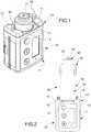
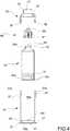
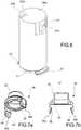
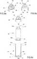
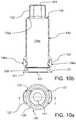
Fig. 1 is a perspective view showing a prior art infusion pump onto which a cartridge with a housing according to the invention can be mounted;Fig. 2 is an elevational view showing the infusion pump ofFig. 1 on which a cartridge with a housing is inserted;Fig. 3 is a perspective view showing part of a cartridge with a housing;Fig. 4 is an exploded view of the cartridge with the housing;Fig. 5 is a longitudinal sectional view of the cartridge shown inFig. 4 ;Fig. 6 is a perspective view of a base part of the housing of the cartridge shown inFig. 4 ;Figs. 7a and 7b are a perspective and a sectional view, respectively, of a neck part of the housing of the cartridge shown inFig. 4 ;Figs. 8a and 8b are a perspective and a sectional view, respectively, of a neck part of the housing in accordance with the invention;Fig. 8c is an exploded view of the cartridge according to the invention;Fig. 9a is a front elevational view showing the infusion pump ofFig. 1 on which a cartridge with a is inserted;Fig. 9b is a side elevational view showing the infusion pump ofFig. 1 on which a cartridge with a housing is inserted;Fig. 9c is a top elevational view showing the infusion pump ofFig. 1 on which a cartridge with a housing is inserted;Fig. 10a is a top elevational view of the housing;Fig. 10b is a longitudinal sectional view taken along plane A-A inFig. 10a ;Fig. 11a is a top elevational view of the base part of the housing shown inFigs. 10 ;Fig. 11b is a longitudinal sectional view taken along plane A-A inFig. 11a ;Fig. 11c is a longitudinal sectional view taken along plane B-B inFig. 11a ;Fig. 12a is a top elevational view of the neck part of the housing shown inFigs. 10 ;Fig. 12b is a longitudinal sectional view taken along plane A-A inFig. 12a ;Fig. 12c is a front elevational view of the neck part of the housing shown inFig. 12a .- In all Figures, the same reference numerals have been used to denote equal or functionally equivalent components.
- Referring to
Figs. 1 and 2 , there is shown aninfusion pump 10, of a type known per se, for controlled administration of drugs to the human or animal body. - Such a device substantially includes a
casing 11 on which asocket 13 is formed for inserting a cartridge. The socket essentially comprises a pair of retainingprojections 14, arranged in fork configuration, on which a pair ofopposite slits 15, facing the fork inside, are formed.Eyelets 16 are provided on retainingprojections 14 surroundingsocket 13. Saideyelet 16 are diametrically opposite with respect to the longitudinal axis of the pump passing through the centre ofsocket 13, and mainly serve for fastening a strap or small chain or the like for suspending the pump, for instance on the bearer's shoulder. An opening, through which apusher 17 can extend outwards, is further provided inside the fork. Such apusher 17 is intended for moving a piston of the cartridge. - For longitudinally moving
pusher 17, an electric motor and associated gears are provided in conventional manner, whereas for controlling the electric motor a programmable control unit is provided in conventional manner. - In order to program the control unit depending on the desired therapeutic program, interface devices can be provided, such as a display and/or light and/or sound indicators, as well as keys and/or other data input devices, located on casing 11 of the device.
- A particular example of the infusion pump described above is represented by the devices of the Crono® series produced and commercialised by the same Applicant.
Fig. 2 shows pump 10 with acartridge 20 inserted insocket 13. In order to allow insertingcartridge 20 ontopump 10, the external surface of the cartridge is conventionally provided with a pair orblades 21 enabling axially inserting the cartridge inside the fork ofsocket 13 and, after the cartridge has been turned by 90° about its longitudinal axis, retaining it inslits 15 of retainingprojections 14.- The connection system disclosed above is given by way of example only, other kinds of bayonet coupling being possible. For instance, cartridge configurations with greater capacity are known, where
fitting formations 21 are formed on the internal surface of the cartridge, and the slits receiving such fitting formations face away from the fork ofsocket 13. - Referring to
Figs. 3 to 7 ,cartridge 20 includes ahousing 30 of plastic material having an openproximal end 31 and an opendistal end 32 and consisting of a cylindrical base part 33 (shown in particular in the Figure) and a neck part 35 (shown in particular inFigs. 7a and 7b ). Base part 33 is substantially shaped as a cylindrical cup having a proximal end and a distal end.Neck part 35 is substantially shaped as an inverted funnel with a neck, and it has a proximal end and a distal end. The proximal end ofbase part 33 coincides with the proximal end ofhousing 30 itself. The distal end ofneck part 35 coincides with the distal end ofhousing 30. Whenhousing 30 is assembled, the distal end ofbase part 33 substantially matches the proximal end ofneck part 35.- In order to enable the mutual fastening of
base part 33 andneck part 35, snap fitting formations are provided, which are integrally formed on the outer surfaces of such parts. In the example illustrated, the snap fitting formations include a pair of diametricallyopposite teeth 36 formed ontabs 36a axially extending fromneck part 35 ofhousing 30, and a pair of diametrically opposite seats oropenings 37, which are formed on the side wall ofbase part 33 ofhousing 30 and into whichteeth 36 are inserted whenhousing 30 is assembled. - In order to make coupling between
teeth 36 andseats 37 easier,tabs 36a provided withteeth 36 may be provided withdraft end portions 36b with rounded or bevelled edges, and seats 37 may be located withinguide grooves 37b. - According to other embodiments, the arrangement of the teeth and the seats may be reversed between the neck and base parts, and the number and the configuration of the elements implementing the snap fitting can be different from those described. Yet, an arrangement is preferred in which the positions of the teeth and the seats are angularly aligned with the positions of bayonet
fitting formations 21, so that the size of the assembly in a direction orthogonal to the direction offitting formations 21 is not increased. - At its
proximal end 31,base part 33 ofhousing 30 has a portion tapered in the proximal direction, the outer diameter of which is reduced with respect to the remaining part ofbase part 33 and on whichfitting formations 21 are formed. - Inside
base part 33 ofhousing 30, a substantiallycylindrical cavity 39a is formed, which is defined at the proximal end by aninternal flange 38 integrally formed onbase part 33 and is located in correspondence of the tapered portion on whichfitting formations 21 are formed.Internal flange 38 thus surrounds anopening 39b having smaller diameter thaninternal cavity 39a ofbase part 33. - Near
internal flange 38, the internal surface ofbase part 33 can be provided withaxial ribs 39c. - At its proximal end,
neck part 35 ofhousing 30 has substantially the same diameter asinternal cavity 39a ofbase part 33. At itsdistal end 32,neck part 35 has anopening 41 with a smaller diameter than the proximal end. - At a position intermediate the proximal and distal ends of
neck part 35 ofhousing 30, a collar-shapedprojection 43, concentrically arranged relative to opening 41, is formed on the internal side ofneck part 35. Cartridge 20 further includes aglass vessel 50 containing a drug and enclosed insidehousing 30.Vessel 50 has a substantially cylindrical shape ending with a neck at a distal end, and has an openproximal end 50a closed by aslidable piston 51 and adistal end 50b with an opening closed by acover 52 equipped with apierceable membrane 53.Cartridge 20 further includes connection means adapted to be arranged atdistal end 50b ofvessel 50.- In the embodiment shown in
Figs. 3 to 7 , such connection means include aconnection element 60 secured todistal end 50b ofvessel 50, for instance secured to cover 52 as a cap, through integral resilient elements which cling around the edge of said cover.Connection element 60 has at a proximal end a piercingelement 61 for piercingmembrane 53 ofvessel 50, and at a distal end aconnector 63, for instance a Luer Lock, for connection to an infusion set including for instance a tube and a needle or needle-cannula (not shown): Through piercingelement 61 and one or more passageways for fluid formed insideconnection element 60, the inside of the vessel is put in communication with the infusion set. Proximal end 50a ofvessel 50 is received withinproximal end 31 ofhousing 30, withpiston 51 being arranged coaxially withopening 39b formed onproximal end 31 ofbase part 33 ofhousing 30. The proper and quick alignment ofpiston 51 withopening 39b is ensured byaxial ribs 39c formed insidebase part 33 ofhousing 30.Base part 33 is so sized in length as to enclose the whole of the cylindrical portion ofvessel 50, or at least most of such portion.Distal end 50b ofvessel 50 is received withindistal end 32 ofhousing 30.- Retention of
vessel 50 insidehousing 30 is ensured in that collar-shapedprojection 43 of the neck part ofhousing 30 rests on the tapered portion ofvessel 50, between the cylindrical portion and the neck thereof, thereby pushingvessel 50 againstinternal flange 38 ofbase part 33 ofhousing 30. - The assembly described above can be inserted onto the pump shown in the Figures, while ensuring that
glass vessel 50 is firmly retained onto the pump thanks toplastic housing 30 enclosing it, and thatpusher 17 of the device can properly reachpiston 51. - In this manner, precise drug doses can be administered in controlled and reliable manner.
- The assembly disclosed above is used as a kit consisting of separate elements, which are assembled at the moment of use. In this case, it is possible either to assemble all parts of
cartridge 20 and subsequently insertcartridge 20 onpump 10, or it is possible first insertingbase part 33 ofhousing 30 onpump 10, and then assembling the other parts to basepart 30 already inserted. - In the alternative, especially in embodiments (not shown) where the vessel is provided with a closing element which is not pierceable but is removable, and where the connection means lack the piercing element, it is possible to conceive that the kit is assembled at industrial level and then delivered to the users in assembled form.
Figs. 8a to 8c show an alternative embodiment, or second embodiment, of the invention, which differs from the embodiment described above only in that it lacks the connection element, and hence in that the functions of piercingelement 61 andconnector 63 for connection to the infusion set are integrally provided onneck part 35 ofhousing 30.Figs. 9 to 12 show a third embodiment of the invention, which substantially differs in the arrangement of the teeth and the seats, which is reversed with respect to the embodiments described above, and in the longitudinal extension of the neck part, which is greater than the longitudinal extension of the base part in comparison to the embodiments described above.- Referring more particularly to
Figs. 9a - 9c ,infusion pump 10 is shown with acartridge 120 inserted insocket 13. In order to allow insertingcartridge 120 ontopump 10, the external surface of the cartridge is conventionally provided with a pair orblades 121 enabling axially inserting the cartridge inside the fork ofsocket 13 and, after the cartridge has been turned by 90° about its longitudinal axis, retaining it inslits 15 of retainingprojections 14. - The connection system disclosed above is given by way of example only, other kinds of bayonet coupling being possible. For instance, cartridge configurations with greater capacity are known, where
fitting formations 121 are formed on the internal surface of the cartridge, and the slits receiving such fitting formations face away from the fork ofsocket 13. - Referring more particularly to
Figs. 10 to 12 ,cartridge 120 includes ahousing 130 of plastic material having an openproximal end 131 and an opendistal end 132 and consisting of a cylindrical base part 133 (shown in particular inFigs. 11 ) and a neck part 135 (shown in particular inFigs. 12 ). Base part 133 is substantially shaped as a cylindrical cup having a proximal end and a distal end.Neck part 135 is substantially shaped as an inverted barrel with a neck, and it has a proximal end and a distal end. The proximal end ofbase part 133 coincides with the proximal end ofhousing 130 itself. The distal end ofneck part 135 coincides with the distal end ofhousing 130. When housing 130 is assembled, the distal end ofbase part 133 substantially matches the proximal end ofneck part 135.- In order to enable the mutual fastening of
base part 133 andneck part 135, snap fitting formations are provided, which are integrally formed on the outer surfaces of such parts. In the example illustrated, the snap fitting formations include a pair of diametricallyopposite teeth 136 formed ontabs 136a axially extending frombase part 133 ofhousing 130, and a pair of diametrically opposite seats oropenings 137, which are formed on the side wall ofneck part 135 ofhousing 130 and into whichteeth 136 are inserted whenhousing 130 is assembled. - In order to make coupling between
teeth 136 andseats 137 easier, the tabs provided withteeth 136 may be provided withdraft end portions 136b with rounded or bevelled edges, and seats 137 may be located withinguide grooves 137b. - In accordance with this third embodiment of the invention,
tabs 136a are preferably located so that, whencartridge 120 is inserted ontopump 10, saidtabs 136a are radially aligned witheyelets 16 provided on retainingprojections 14, arranged in fork configuration, ofpump 10. Moreover,base part 133 ofhousing 130 is suitably sized so that saidtabs 136a are in contact witheyelets 16. In other words, eyelets 16 define an abutment shoulder fortabs 136a and consequently prevent outward radial movement thereof. - Advantageously, thanks to such an arrangement, eyelets 16 prevent
tabs 136a from radially opening outwards, thereby avoiding the risk thatneck part 135 becomes released frombase part 133 ofhousing 130, especially whenpiston 17 ofpump 10 exerts the pushing force onpiston 51 ofvessel 50. Whencartridge 120 is inserted ontopump 10 withvessel 50 inside it, consequentlyneck part 35 cannot be removed frombase part 133 thanks to the engagement ofteeth 136 withseats 137 and thanks to the fact thattabs 136a provided withteeth 136 cannot open out outwards due to the provision ofeyelets 16. - Other configurations will be possible in which eyelets 16 are replaced by corresponding stop members for
tabs 136a. For instance, said corresponding stop members could consist of projections integrally formed in retainingprojections 14, or of heads of screws for fastening retainingprojections 14. - Advantageously, in accordance with a particular embodiment of the invention, each
tab 136a can include two ormore teeth 136 and, on the side wall ofneck part 135 ofhousing 130, there are formed as many seats oropenings 137 into whichteeth 136 are inserted whenhousing 130 is assembled. The two ormore teeth 136 provided on eachtab 136a can also have mutually different sizes, and preferably the teeth size decreases towards thedraft end portion 136b. - At its
proximal end 131,base part 133 ofhousing 130 has a portion tapered in proximal direction, the diameter of which is reduced with respect to the remaining part ofbase part 133 and on whichfitting formations 121 are formed. Inside neck part 135 ofhousing 130, a substantiallycylindrical cavity 139a is formed. At its proximal end,neck part 135 ofhousing 130 has substantially the same diameter as the distal end ofbase part 133. At itsdistal end 132,neck part 135 has anopening 141 with smaller diameter than its proximal end.Base part 133 ofhousing 130 is defined at its proximal end by aninternal flange 138, integrally formed onbase part 133 and located in correspondence of the tapered portion on whichfitting formations 21 are formed.Internal flange 138 thus surrounds anopening 139b having a smaller diameter thaninternal cavity 139a ofneck part 135.- Similarly to the previously described embodiments,
cartridge 120 of whichhousing 130 is part further includes aglass vessel 50 containing a drug and enclosed insidehousing 30. Cartridge 120 further includes connection means adapted to be arranged atdistal end 50b ofvessel 50.Proximal end 50a ofvessel 50 is received withinproximal end 131 ofhousing 130, withpiston 51 being arranged coaxially to opening 139b formed onproximal end 131 ofbase part 133 ofhousing 130. The proper and quick alignment ofpiston 51 withopening 139b is possibly ensured by axial ribs formed insidebase part 133 ofhousing 130.Neck part 135 is so sized in length as to enclose the whole of the cylindrical portion ofvessel 50, or at least most of such portion.Distal end 50b ofvessel 50 is received withindistal end 132 ofhousing 130.- Retention of
vessel 50 insidehousing 130 is ensured in thatdistal end 132 ofneck part 135 has a taperedinner wall 132a forming acorresponding abutment surface 132a and resting on the tapered portion ofvessel 50, between the cylindrical portion and the neck thereof, thereby pushingvessel 50 againstinternal flange 138 ofbase part 133 ofhousing 130. - In the alternative, a small passageway can be provided between
surface 132a andvessel 50, andvessel 50 can be retained in correspondence ofbase part 133, for instance through the mutual engagement betweenannular projection 50c provided at the base ofvessel 50 and a corresponding annular seat (not shown) provided inbase part 133. - The assembly described above can be inserted onto the pump shown in
Figs. 9 , while ensuring thatglass vessel 50 is firmly kept onto the pump thanks toplastic housing 130 enclosing it, and thatpusher 17 of the device can properly reachpiston 51. In this manner, precise drug doses can be administered in controlled and reliable manner.
Claims (9)
- Housing (30, 130) for a cartridge (20; 120) for an infusion pump (10) for controlled administration of drugs to the human or animal body, said housing being adapted to enclose a glass vessel (50) of cylindrical shape, having an open proximal end (50a) closed by a slidable piston (51) and a distal end (50b) provided with a neck, wherein said housing (30; 130) is made of plastic material and has a proximal end (31; 131) and a distal end (32; 132) adapted to receive the proximal end (50a) and the distal end (50b) of the vessel (50), respectively, wherein the proximal end (31; 131) of the housing (30; 130) is provided with a pair of bayonet fitting formations (21; 121) integrally formed on the housing (30; 130), and adapted to enable the cartridge to be fastened to an infusion pump (10), wherein the housing (30; 130) consists of a cylindrical base part (33; 133), which is provided with an inner flange (38; 138) for abutment of the vessel (50) and on which the fitting formations (21; 121) are formed, and a neck part (35; 135) that can be fastened to the base part (33; 133), wherein connection means are provided adapted to be arranged at a distal end (50b) of the vessel (50) for fluidically connecting the inside of the vessel (50) to an infusion set and comprising at a proximal end a piercing element (61) for piercing a membrane (53) of the vessel (50), and at a distal end a fitting (63) for connection to an infusion set,characterized in that the neck part (35;135) can be fastened to the base part (33;133) by means of snap fitting formations (36, 37; 136, 137) for retaining the glass vessel (50) between the base part (33; 133) and the neck part (35; 135) of the housing (30; 130) andin that said connection means (61, 63) are integrally formed on the neck part (35; 135) of the housing (30; 130), the snap fitting formations are configured so as to make separation of the neck part (35; 135) from the base part (33; 133) difficult or substantially impossible, whereby the cartridge and its housing substantially form a disposable assembly.
- Housing according to claim 1, wherein the base part (33; 133) is sized in length so as to enclose the whole of the cylindrical portion of the vessel (50), or at least most of such portion.
- Housing according to any of the preceding claims, wherein the snap fitting formations comprise a pair of diametrically opposite teeth (36; 136) formed on the neck part (35; 135) of the housing (30; 130), and a pair of diametrically opposite seats (37; 137) formed on the base part (33; 133) of the housing (30; 130).
- Housing according to claim 1, wherein the neck part (35; 135) is sized in length so as to enclose the whole of the cylindrical portion of the vessel (50), or at least most of such portion.
- Housing according to claim 1 or 4, wherein the snap fitting formations comprise a pair of diametrically opposite teeth (36; 136) formed on the base part (33; 133) of the housing (30; 130), and a pair of diametrically opposite seats (37; 137) formed on the neck part (35; 135) of the housing (30; 130).
- Housing according to any of claims from 1 to 5, wherein the neck part (35; 135) of the housing (30; 130) has an opening (41; 141) sized so as to enable connection means, arranged at the distal end (50b) of the vessel (50), to outwardly protrude for fluidically connecting the inside of the vessel (50) to an infusion set.
- Kit for an infusion pump cartridge (20) for controlled administration of drugs to the human or animal body, said kit comprising a glass vessel (50) of cylindrical shape having an open proximal end (50a) closed by a slidable piston (51) and a distal end (50b) provided with a neck, and a housing according to any of the preceding claims.
- Kit according to claim 9, wherein the neck of the vessel (50) has an opening closed by a pierceable membrane (53).
- Cartridge formed from a kit according to any of claims 9 to 10.
Priority Applications (3)
| Application Number | Priority Date | Filing Date | Title |
|---|---|---|---|
| US16/468,786US11684711B2 (en) | 2016-12-13 | 2017-12-13 | Housing for a cartridge for distribution and administration of drugs by means of portable infusion pumps |
| EP17830006.7AEP3554583B1 (en) | 2016-12-13 | 2017-12-13 | Housing for a cartridge for distribution and administration of drugs by means of portable infusion pumps |
| PCT/IB2017/057899WO2018109689A1 (en) | 2016-12-13 | 2017-12-13 | Housing for a cartridge for distribution and administration of drugs by means of portable infusion pumps |
Applications Claiming Priority (1)
| Application Number | Priority Date | Filing Date | Title |
|---|---|---|---|
| ITUA2016A004349AITUA20164349A1 (en) | 2016-06-14 | 2016-06-14 | Cartridge case for dispensing and administering drugs via portable infusion pumps. |
Publications (2)
| Publication Number | Publication Date |
|---|---|
| EP3257533A1 EP3257533A1 (en) | 2017-12-20 |
| EP3257533B1true EP3257533B1 (en) | 2019-11-27 |
Family
ID=57184660
Family Applications (1)
| Application Number | Title | Priority Date | Filing Date |
|---|---|---|---|
| EP16203893.9AActiveEP3257533B1 (en) | 2016-06-14 | 2016-12-13 | Housing for a cartridge for distribution and administration of drugs by means of portable infusion pumps |
Country Status (2)
| Country | Link |
|---|---|
| EP (1) | EP3257533B1 (en) |
| IT (1) | ITUA20164349A1 (en) |
Families Citing this family (7)
| Publication number | Priority date | Publication date | Assignee | Title |
|---|---|---|---|---|
| EP1762259B2 (en) | 2005-09-12 | 2025-01-01 | Unomedical A/S | Inserter for an infusion set with a first and second spring units |
| WO2012123274A1 (en) | 2011-03-14 | 2012-09-20 | Unomedical A/S | Inserter system with transport protection |
| IT201800006427A1 (en) | 2018-06-18 | 2019-12-18 | Compact, quick-charge safety pump for drug administration | |
| US11458292B2 (en) | 2019-05-20 | 2022-10-04 | Unomedical A/S | Rotatable infusion device and methods thereof |
| FR3100719B1 (en)* | 2019-09-12 | 2023-04-14 | Ad Hoc Scient | Injection part for syringe glass cartridge |
| WO2023066679A1 (en)* | 2021-10-19 | 2023-04-27 | Shl Medical Ag | A medicament container carrier of a medicament delivery device and a method of assembling a medicament delivery device medicament container assembly |
| EP3960220A1 (en) | 2020-09-01 | 2022-03-02 | TecMed AG | Fixation of reservoir of drug delivery device |
Family Cites Families (3)
| Publication number | Priority date | Publication date | Assignee | Title |
|---|---|---|---|---|
| US6022337A (en)* | 1997-09-04 | 2000-02-08 | Herbst; Walter | Dental anesthetic and delivery injection unit |
| WO2009043564A1 (en)* | 2007-10-01 | 2009-04-09 | Roche Diagnostics Gmbh | Cartridge adapter for use in an infusion system |
| CA2806989A1 (en)* | 2010-08-06 | 2012-02-09 | Sanofi-Aventis Deutschland Gmbh | Method and system for retaining a cartridge in a holder |
- 2016
- 2016-06-14ITITUA2016A004349Apatent/ITUA20164349A1/enunknown
- 2016-12-13EPEP16203893.9Apatent/EP3257533B1/enactiveActive
Non-Patent Citations (1)
| Title |
|---|
| None* |
Also Published As
| Publication number | Publication date |
|---|---|
| ITUA20164349A1 (en) | 2017-12-14 |
| EP3257533A1 (en) | 2017-12-20 |
Similar Documents
| Publication | Publication Date | Title |
|---|---|---|
| EP3554583B1 (en) | Housing for a cartridge for distribution and administration of drugs by means of portable infusion pumps | |
| EP3257533B1 (en) | Housing for a cartridge for distribution and administration of drugs by means of portable infusion pumps | |
| US11992665B2 (en) | Needle cover | |
| KR102179171B1 (en) | Auto-injector device | |
| JP6725563B2 (en) | Subcutaneous infusion set with side port fluid connector | |
| EP1329233B1 (en) | Container for disposable needle | |
| EP0941133B1 (en) | Disposable, pre-filled drug cartridge | |
| US20050277896A1 (en) | Device for securing injection needles | |
| CN102802704A (en) | Drug delivery device with cap function for needle assembly | |
| JP2009545341A (en) | Cannula and delivery device | |
| JP7325426B2 (en) | pen needle instrument | |
| JP2013528080A (en) | Devices and cases for infusion devices | |
| US12186542B2 (en) | Detachable needle protection cap for injection devices | |
| EP4237043A1 (en) | Administration device for in particular intravitreal administration of a fluid | |
| EP3603705B1 (en) | Syringe | |
| EP3806930B1 (en) | Safety quick-refill compact pump for administering drugs | |
| CA2909254A1 (en) | Drug administering device and assembly method therefore | |
| US20210178076A1 (en) | Drug delivery system with drug differentiation feature | |
| CN119384298A (en) | Filling auxiliary components | |
| EP2022520B1 (en) | Drug infusion device equipped with a syringe having a pair of tabs |
Legal Events
| Date | Code | Title | Description |
|---|---|---|---|
| PUAI | Public reference made under article 153(3) epc to a published international application that has entered the european phase | Free format text:ORIGINAL CODE: 0009012 | |
| STAA | Information on the status of an ep patent application or granted ep patent | Free format text:STATUS: THE APPLICATION HAS BEEN PUBLISHED | |
| AK | Designated contracting states | Kind code of ref document:A1 Designated state(s):AL AT BE BG CH CY CZ DE DK EE ES FI FR GB GR HR HU IE IS IT LI LT LU LV MC MK MT NL NO PL PT RO RS SE SI SK SM TR | |
| AX | Request for extension of the european patent | Extension state:BA ME | |
| STAA | Information on the status of an ep patent application or granted ep patent | Free format text:STATUS: REQUEST FOR EXAMINATION WAS MADE | |
| 17P | Request for examination filed | Effective date:20180620 | |
| RBV | Designated contracting states (corrected) | Designated state(s):AL AT BE BG CH CY CZ DE DK EE ES FI FR GB GR HR HU IE IS IT LI LT LU LV MC MK MT NL NO PL PT RO RS SE SI SK SM TR | |
| GRAP | Despatch of communication of intention to grant a patent | Free format text:ORIGINAL CODE: EPIDOSNIGR1 | |
| STAA | Information on the status of an ep patent application or granted ep patent | Free format text:STATUS: GRANT OF PATENT IS INTENDED | |
| INTG | Intention to grant announced | Effective date:20190506 | |
| RIN1 | Information on inventor provided before grant (corrected) | Inventor name:CANE', MARIO Inventor name:CANE', PAOLO Inventor name:CANE', CLAUDIO | |
| GRAS | Grant fee paid | Free format text:ORIGINAL CODE: EPIDOSNIGR3 | |
| GRAJ | Information related to disapproval of communication of intention to grant by the applicant or resumption of examination proceedings by the epo deleted | Free format text:ORIGINAL CODE: EPIDOSDIGR1 | |
| GRAL | Information related to payment of fee for publishing/printing deleted | Free format text:ORIGINAL CODE: EPIDOSDIGR3 | |
| STAA | Information on the status of an ep patent application or granted ep patent | Free format text:STATUS: REQUEST FOR EXAMINATION WAS MADE | |
| GRAR | Information related to intention to grant a patent recorded | Free format text:ORIGINAL CODE: EPIDOSNIGR71 | |
| STAA | Information on the status of an ep patent application or granted ep patent | Free format text:STATUS: GRANT OF PATENT IS INTENDED | |
| INTC | Intention to grant announced (deleted) | ||
| GRAA | (expected) grant | Free format text:ORIGINAL CODE: 0009210 | |
| STAA | Information on the status of an ep patent application or granted ep patent | Free format text:STATUS: THE PATENT HAS BEEN GRANTED | |
| INTG | Intention to grant announced | Effective date:20191016 | |
| AK | Designated contracting states | Kind code of ref document:B1 Designated state(s):AL AT BE BG CH CY CZ DE DK EE ES FI FR GB GR HR HU IE IS IT LI LT LU LV MC MK MT NL NO PL PT RO RS SE SI SK SM TR | |
| REG | Reference to a national code | Ref country code:GB Ref legal event code:FG4D | |
| REG | Reference to a national code | Ref country code:CH Ref legal event code:EP | |
| REG | Reference to a national code | Ref country code:AT Ref legal event code:REF Ref document number:1205998 Country of ref document:AT Kind code of ref document:T Effective date:20191215 | |
| REG | Reference to a national code | Ref country code:DE Ref legal event code:R096 Ref document number:602016025006 Country of ref document:DE | |
| REG | Reference to a national code | Ref country code:IE Ref legal event code:FG4D | |
| REG | Reference to a national code | Ref country code:NL Ref legal event code:MP Effective date:20191127 | |
| REG | Reference to a national code | Ref country code:LT Ref legal event code:MG4D | |
| PG25 | Lapsed in a contracting state [announced via postgrant information from national office to epo] | Ref country code:LT Free format text:LAPSE BECAUSE OF FAILURE TO SUBMIT A TRANSLATION OF THE DESCRIPTION OR TO PAY THE FEE WITHIN THE PRESCRIBED TIME-LIMIT Effective date:20191127 Ref country code:NL Free format text:LAPSE BECAUSE OF FAILURE TO SUBMIT A TRANSLATION OF THE DESCRIPTION OR TO PAY THE FEE WITHIN THE PRESCRIBED TIME-LIMIT Effective date:20191127 Ref country code:GR Free format text:LAPSE BECAUSE OF FAILURE TO SUBMIT A TRANSLATION OF THE DESCRIPTION OR TO PAY THE FEE WITHIN THE PRESCRIBED TIME-LIMIT Effective date:20200228 Ref country code:SE Free format text:LAPSE BECAUSE OF FAILURE TO SUBMIT A TRANSLATION OF THE DESCRIPTION OR TO PAY THE FEE WITHIN THE PRESCRIBED TIME-LIMIT Effective date:20191127 Ref country code:NO Free format text:LAPSE BECAUSE OF FAILURE TO SUBMIT A TRANSLATION OF THE DESCRIPTION OR TO PAY THE FEE WITHIN THE PRESCRIBED TIME-LIMIT Effective date:20200227 Ref country code:LV Free format text:LAPSE BECAUSE OF FAILURE TO SUBMIT A TRANSLATION OF THE DESCRIPTION OR TO PAY THE FEE WITHIN THE PRESCRIBED TIME-LIMIT Effective date:20191127 Ref country code:FI Free format text:LAPSE BECAUSE OF FAILURE TO SUBMIT A TRANSLATION OF THE DESCRIPTION OR TO PAY THE FEE WITHIN THE PRESCRIBED TIME-LIMIT Effective date:20191127 Ref country code:BG Free format text:LAPSE BECAUSE OF FAILURE TO SUBMIT A TRANSLATION OF THE DESCRIPTION OR TO PAY THE FEE WITHIN THE PRESCRIBED TIME-LIMIT Effective date:20200227 | |
| PG25 | Lapsed in a contracting state [announced via postgrant information from national office to epo] | Ref country code:IS Free format text:LAPSE BECAUSE OF FAILURE TO SUBMIT A TRANSLATION OF THE DESCRIPTION OR TO PAY THE FEE WITHIN THE PRESCRIBED TIME-LIMIT Effective date:20200327 Ref country code:HR Free format text:LAPSE BECAUSE OF FAILURE TO SUBMIT A TRANSLATION OF THE DESCRIPTION OR TO PAY THE FEE WITHIN THE PRESCRIBED TIME-LIMIT Effective date:20191127 Ref country code:RS Free format text:LAPSE BECAUSE OF FAILURE TO SUBMIT A TRANSLATION OF THE DESCRIPTION OR TO PAY THE FEE WITHIN THE PRESCRIBED TIME-LIMIT Effective date:20191127 | |
| PG25 | Lapsed in a contracting state [announced via postgrant information from national office to epo] | Ref country code:AL Free format text:LAPSE BECAUSE OF FAILURE TO SUBMIT A TRANSLATION OF THE DESCRIPTION OR TO PAY THE FEE WITHIN THE PRESCRIBED TIME-LIMIT Effective date:20191127 | |
| PG25 | Lapsed in a contracting state [announced via postgrant information from national office to epo] | Ref country code:RO Free format text:LAPSE BECAUSE OF FAILURE TO SUBMIT A TRANSLATION OF THE DESCRIPTION OR TO PAY THE FEE WITHIN THE PRESCRIBED TIME-LIMIT Effective date:20191127 Ref country code:CZ Free format text:LAPSE BECAUSE OF FAILURE TO SUBMIT A TRANSLATION OF THE DESCRIPTION OR TO PAY THE FEE WITHIN THE PRESCRIBED TIME-LIMIT Effective date:20191127 Ref country code:ES Free format text:LAPSE BECAUSE OF FAILURE TO SUBMIT A TRANSLATION OF THE DESCRIPTION OR TO PAY THE FEE WITHIN THE PRESCRIBED TIME-LIMIT Effective date:20191127 Ref country code:PT Free format text:LAPSE BECAUSE OF FAILURE TO SUBMIT A TRANSLATION OF THE DESCRIPTION OR TO PAY THE FEE WITHIN THE PRESCRIBED TIME-LIMIT Effective date:20200419 Ref country code:EE Free format text:LAPSE BECAUSE OF FAILURE TO SUBMIT A TRANSLATION OF THE DESCRIPTION OR TO PAY THE FEE WITHIN THE PRESCRIBED TIME-LIMIT Effective date:20191127 Ref country code:DK Free format text:LAPSE BECAUSE OF FAILURE TO SUBMIT A TRANSLATION OF THE DESCRIPTION OR TO PAY THE FEE WITHIN THE PRESCRIBED TIME-LIMIT Effective date:20191127 | |
| REG | Reference to a national code | Ref country code:CH Ref legal event code:PL | |
| REG | Reference to a national code | Ref country code:BE Ref legal event code:MM Effective date:20191231 | |
| REG | Reference to a national code | Ref country code:DE Ref legal event code:R097 Ref document number:602016025006 Country of ref document:DE | |
| PG25 | Lapsed in a contracting state [announced via postgrant information from national office to epo] | Ref country code:SM Free format text:LAPSE BECAUSE OF FAILURE TO SUBMIT A TRANSLATION OF THE DESCRIPTION OR TO PAY THE FEE WITHIN THE PRESCRIBED TIME-LIMIT Effective date:20191127 Ref country code:SK Free format text:LAPSE BECAUSE OF FAILURE TO SUBMIT A TRANSLATION OF THE DESCRIPTION OR TO PAY THE FEE WITHIN THE PRESCRIBED TIME-LIMIT Effective date:20191127 Ref country code:MC Free format text:LAPSE BECAUSE OF FAILURE TO SUBMIT A TRANSLATION OF THE DESCRIPTION OR TO PAY THE FEE WITHIN THE PRESCRIBED TIME-LIMIT Effective date:20191127 | |
| REG | Reference to a national code | Ref country code:AT Ref legal event code:MK05 Ref document number:1205998 Country of ref document:AT Kind code of ref document:T Effective date:20191127 | |
| PLBE | No opposition filed within time limit | Free format text:ORIGINAL CODE: 0009261 | |
| STAA | Information on the status of an ep patent application or granted ep patent | Free format text:STATUS: NO OPPOSITION FILED WITHIN TIME LIMIT | |
| PG25 | Lapsed in a contracting state [announced via postgrant information from national office to epo] | Ref country code:LU Free format text:LAPSE BECAUSE OF NON-PAYMENT OF DUE FEES Effective date:20191213 Ref country code:IE Free format text:LAPSE BECAUSE OF NON-PAYMENT OF DUE FEES Effective date:20191213 | |
| 26N | No opposition filed | Effective date:20200828 | |
| PG25 | Lapsed in a contracting state [announced via postgrant information from national office to epo] | Ref country code:CH Free format text:LAPSE BECAUSE OF NON-PAYMENT OF DUE FEES Effective date:20191231 Ref country code:AT Free format text:LAPSE BECAUSE OF FAILURE TO SUBMIT A TRANSLATION OF THE DESCRIPTION OR TO PAY THE FEE WITHIN THE PRESCRIBED TIME-LIMIT Effective date:20191127 Ref country code:SI Free format text:LAPSE BECAUSE OF FAILURE TO SUBMIT A TRANSLATION OF THE DESCRIPTION OR TO PAY THE FEE WITHIN THE PRESCRIBED TIME-LIMIT Effective date:20191127 Ref country code:LI Free format text:LAPSE BECAUSE OF NON-PAYMENT OF DUE FEES Effective date:20191231 Ref country code:PL Free format text:LAPSE BECAUSE OF FAILURE TO SUBMIT A TRANSLATION OF THE DESCRIPTION OR TO PAY THE FEE WITHIN THE PRESCRIBED TIME-LIMIT Effective date:20191127 Ref country code:BE Free format text:LAPSE BECAUSE OF NON-PAYMENT OF DUE FEES Effective date:20191231 | |
| PG25 | Lapsed in a contracting state [announced via postgrant information from national office to epo] | Ref country code:IT Free format text:LAPSE BECAUSE OF FAILURE TO SUBMIT A TRANSLATION OF THE DESCRIPTION OR TO PAY THE FEE WITHIN THE PRESCRIBED TIME-LIMIT Effective date:20191127 | |
| PG25 | Lapsed in a contracting state [announced via postgrant information from national office to epo] | Ref country code:CY Free format text:LAPSE BECAUSE OF FAILURE TO SUBMIT A TRANSLATION OF THE DESCRIPTION OR TO PAY THE FEE WITHIN THE PRESCRIBED TIME-LIMIT Effective date:20191127 | |
| PG25 | Lapsed in a contracting state [announced via postgrant information from national office to epo] | Ref country code:HU Free format text:LAPSE BECAUSE OF FAILURE TO SUBMIT A TRANSLATION OF THE DESCRIPTION OR TO PAY THE FEE WITHIN THE PRESCRIBED TIME-LIMIT; INVALID AB INITIO Effective date:20161213 Ref country code:MT Free format text:LAPSE BECAUSE OF FAILURE TO SUBMIT A TRANSLATION OF THE DESCRIPTION OR TO PAY THE FEE WITHIN THE PRESCRIBED TIME-LIMIT Effective date:20191127 | |
| PG25 | Lapsed in a contracting state [announced via postgrant information from national office to epo] | Ref country code:TR Free format text:LAPSE BECAUSE OF FAILURE TO SUBMIT A TRANSLATION OF THE DESCRIPTION OR TO PAY THE FEE WITHIN THE PRESCRIBED TIME-LIMIT Effective date:20191127 | |
| PG25 | Lapsed in a contracting state [announced via postgrant information from national office to epo] | Ref country code:MK Free format text:LAPSE BECAUSE OF FAILURE TO SUBMIT A TRANSLATION OF THE DESCRIPTION OR TO PAY THE FEE WITHIN THE PRESCRIBED TIME-LIMIT Effective date:20191127 | |
| PGFP | Annual fee paid to national office [announced via postgrant information from national office to epo] | Ref country code:DE Payment date:20241212 Year of fee payment:9 | |
| PGFP | Annual fee paid to national office [announced via postgrant information from national office to epo] | Ref country code:GB Payment date:20241230 Year of fee payment:9 | |
| PGFP | Annual fee paid to national office [announced via postgrant information from national office to epo] | Ref country code:FR Payment date:20241127 Year of fee payment:9 |