EP3256387B1 - Filling system for electronic smoking devices - Google Patents
Filling system for electronic smoking devicesDownload PDFInfo
- Publication number
- EP3256387B1 EP3256387B1EP16704225.8AEP16704225AEP3256387B1EP 3256387 B1EP3256387 B1EP 3256387B1EP 16704225 AEP16704225 AEP 16704225AEP 3256387 B1EP3256387 B1EP 3256387B1
- Authority
- EP
- European Patent Office
- Prior art keywords
- nozzle
- liquid
- plunger
- air tube
- opening
- Prior art date
- Legal status (The legal status is an assumption and is not a legal conclusion. Google has not performed a legal analysis and makes no representation as to the accuracy of the status listed.)
- Active
Links
Images


Classifications
- A—HUMAN NECESSITIES
- A24—TOBACCO; CIGARS; CIGARETTES; SIMULATED SMOKING DEVICES; SMOKERS' REQUISITES
- A24F—SMOKERS' REQUISITES; MATCH BOXES; SIMULATED SMOKING DEVICES
- A24F40/00—Electrically operated smoking devices; Component parts thereof; Manufacture thereof; Maintenance or testing thereof; Charging means specially adapted therefor
- A24F40/40—Constructional details, e.g. connection of cartridges and battery parts
- A24F40/42—Cartridges or containers for inhalable precursors
- B—PERFORMING OPERATIONS; TRANSPORTING
- B65—CONVEYING; PACKING; STORING; HANDLING THIN OR FILAMENTARY MATERIAL
- B65B—MACHINES, APPARATUS OR DEVICES FOR, OR METHODS OF, PACKAGING ARTICLES OR MATERIALS; UNPACKING
- B65B3/00—Packaging plastic material, semiliquids, liquids or mixed solids and liquids, in individual containers or receptacles, e.g. bags, sacks, boxes, cartons, cans, or jars
- B65B3/04—Methods of, or means for, filling the material into the containers or receptacles
- B65B3/10—Methods of, or means for, filling the material into the containers or receptacles by application of pressure to material
- B65B3/12—Methods of, or means for, filling the material into the containers or receptacles by application of pressure to material mechanically, e.g. by pistons or pumps
- B—PERFORMING OPERATIONS; TRANSPORTING
- B65—CONVEYING; PACKING; STORING; HANDLING THIN OR FILAMENTARY MATERIAL
- B65B—MACHINES, APPARATUS OR DEVICES FOR, OR METHODS OF, PACKAGING ARTICLES OR MATERIALS; UNPACKING
- B65B39/00—Nozzles, funnels or guides for introducing articles or materials into containers or wrappers
- B65B39/001—Nozzles, funnels or guides for introducing articles or materials into containers or wrappers with flow cut-off means, e.g. valves
- A—HUMAN NECESSITIES
- A24—TOBACCO; CIGARS; CIGARETTES; SIMULATED SMOKING DEVICES; SMOKERS' REQUISITES
- A24F—SMOKERS' REQUISITES; MATCH BOXES; SIMULATED SMOKING DEVICES
- A24F40/00—Electrically operated smoking devices; Component parts thereof; Manufacture thereof; Maintenance or testing thereof; Charging means specially adapted therefor
- A24F40/40—Constructional details, e.g. connection of cartridges and battery parts
- A24F40/48—Fluid transfer means, e.g. pumps
- A24F40/485—Valves; Apertures
- A—HUMAN NECESSITIES
- A24—TOBACCO; CIGARS; CIGARETTES; SIMULATED SMOKING DEVICES; SMOKERS' REQUISITES
- A24F—SMOKERS' REQUISITES; MATCH BOXES; SIMULATED SMOKING DEVICES
- A24F47/00—Smokers' requisites not otherwise provided for
- A—HUMAN NECESSITIES
- A61—MEDICAL OR VETERINARY SCIENCE; HYGIENE
- A61M—DEVICES FOR INTRODUCING MEDIA INTO, OR ONTO, THE BODY; DEVICES FOR TRANSDUCING BODY MEDIA OR FOR TAKING MEDIA FROM THE BODY; DEVICES FOR PRODUCING OR ENDING SLEEP OR STUPOR
- A61M11/00—Sprayers or atomisers specially adapted for therapeutic purposes
- A61M11/04—Sprayers or atomisers specially adapted for therapeutic purposes operated by the vapour pressure of the liquid to be sprayed or atomised
- A61M11/041—Sprayers or atomisers specially adapted for therapeutic purposes operated by the vapour pressure of the liquid to be sprayed or atomised using heaters
- A61M11/042—Sprayers or atomisers specially adapted for therapeutic purposes operated by the vapour pressure of the liquid to be sprayed or atomised using heaters electrical
- A—HUMAN NECESSITIES
- A61—MEDICAL OR VETERINARY SCIENCE; HYGIENE
- A61M—DEVICES FOR INTRODUCING MEDIA INTO, OR ONTO, THE BODY; DEVICES FOR TRANSDUCING BODY MEDIA OR FOR TAKING MEDIA FROM THE BODY; DEVICES FOR PRODUCING OR ENDING SLEEP OR STUPOR
- A61M15/00—Inhalators
- A61M15/06—Inhaling appliances shaped like cigars, cigarettes or pipes
- B—PERFORMING OPERATIONS; TRANSPORTING
- B05—SPRAYING OR ATOMISING IN GENERAL; APPLYING FLUENT MATERIALS TO SURFACES, IN GENERAL
- B05B—SPRAYING APPARATUS; ATOMISING APPARATUS; NOZZLES
- B05B11/00—Single-unit hand-held apparatus in which flow of contents is produced by the muscular force of the operator at the moment of use
- B05B11/0002—Single-unit hand-held apparatus in which flow of contents is produced by the muscular force of the operator at the moment of use incorporating means for heating or cooling, e.g. the material to be sprayed
- B—PERFORMING OPERATIONS; TRANSPORTING
- B05—SPRAYING OR ATOMISING IN GENERAL; APPLYING FLUENT MATERIALS TO SURFACES, IN GENERAL
- B05B—SPRAYING APPARATUS; ATOMISING APPARATUS; NOZZLES
- B05B11/00—Single-unit hand-held apparatus in which flow of contents is produced by the muscular force of the operator at the moment of use
- B05B11/0005—Components or details
- B05B11/0037—Containers
- B05B11/0039—Containers associated with means for compensating the pressure difference between the ambient pressure and the pressure inside the container, e.g. pressure relief means
- B05B11/0044—Containers associated with means for compensating the pressure difference between the ambient pressure and the pressure inside the container, e.g. pressure relief means compensating underpressure by ingress of atmospheric air into the container, i.e. with venting means
- B—PERFORMING OPERATIONS; TRANSPORTING
- B05—SPRAYING OR ATOMISING IN GENERAL; APPLYING FLUENT MATERIALS TO SURFACES, IN GENERAL
- B05B—SPRAYING APPARATUS; ATOMISING APPARATUS; NOZZLES
- B05B11/00—Single-unit hand-held apparatus in which flow of contents is produced by the muscular force of the operator at the moment of use
- B05B11/0005—Components or details
- B05B11/0097—Means for filling or refilling the sprayer
- B—PERFORMING OPERATIONS; TRANSPORTING
- B65—CONVEYING; PACKING; STORING; HANDLING THIN OR FILAMENTARY MATERIAL
- B65B—MACHINES, APPARATUS OR DEVICES FOR, OR METHODS OF, PACKAGING ARTICLES OR MATERIALS; UNPACKING
- B65B3/00—Packaging plastic material, semiliquids, liquids or mixed solids and liquids, in individual containers or receptacles, e.g. bags, sacks, boxes, cartons, cans, or jars
- B65B3/04—Methods of, or means for, filling the material into the containers or receptacles
- B65B3/06—Methods of, or means for, filling the material into the containers or receptacles by gravity flow
- B—PERFORMING OPERATIONS; TRANSPORTING
- B65—CONVEYING; PACKING; STORING; HANDLING THIN OR FILAMENTARY MATERIAL
- B65D—CONTAINERS FOR STORAGE OR TRANSPORT OF ARTICLES OR MATERIALS, e.g. BAGS, BARRELS, BOTTLES, BOXES, CANS, CARTONS, CRATES, DRUMS, JARS, TANKS, HOPPERS, FORWARDING CONTAINERS; ACCESSORIES, CLOSURES, OR FITTINGS THEREFOR; PACKAGING ELEMENTS; PACKAGES
- B65D1/00—Rigid or semi-rigid containers having bodies formed in one piece, e.g. by casting metallic material, by moulding plastics, by blowing vitreous material, by throwing ceramic material, by moulding pulped fibrous material or by deep-drawing operations performed on sheet material
- B65D1/32—Containers adapted to be temporarily deformed by external pressure to expel contents
- B—PERFORMING OPERATIONS; TRANSPORTING
- B65—CONVEYING; PACKING; STORING; HANDLING THIN OR FILAMENTARY MATERIAL
- B65D—CONTAINERS FOR STORAGE OR TRANSPORT OF ARTICLES OR MATERIALS, e.g. BAGS, BARRELS, BOTTLES, BOXES, CANS, CARTONS, CRATES, DRUMS, JARS, TANKS, HOPPERS, FORWARDING CONTAINERS; ACCESSORIES, CLOSURES, OR FITTINGS THEREFOR; PACKAGING ELEMENTS; PACKAGES
- B65D47/00—Closures with filling and discharging, or with discharging, devices
- B65D47/04—Closures with discharging devices other than pumps
- B65D47/06—Closures with discharging devices other than pumps with pouring spouts or tubes; with discharge nozzles or passages
- B—PERFORMING OPERATIONS; TRANSPORTING
- B65—CONVEYING; PACKING; STORING; HANDLING THIN OR FILAMENTARY MATERIAL
- B65D—CONTAINERS FOR STORAGE OR TRANSPORT OF ARTICLES OR MATERIALS, e.g. BAGS, BARRELS, BOTTLES, BOXES, CANS, CARTONS, CRATES, DRUMS, JARS, TANKS, HOPPERS, FORWARDING CONTAINERS; ACCESSORIES, CLOSURES, OR FITTINGS THEREFOR; PACKAGING ELEMENTS; PACKAGES
- B65D47/00—Closures with filling and discharging, or with discharging, devices
- B65D47/04—Closures with discharging devices other than pumps
- B65D47/20—Closures with discharging devices other than pumps comprising hand-operated members for controlling discharge
- B65D47/24—Closures with discharging devices other than pumps comprising hand-operated members for controlling discharge with poppet valves or lift valves, i.e. valves opening or closing a passageway by a relative motion substantially perpendicular to the plane of the seat
- B65D47/241—Closures with discharging devices other than pumps comprising hand-operated members for controlling discharge with poppet valves or lift valves, i.e. valves opening or closing a passageway by a relative motion substantially perpendicular to the plane of the seat the valve being opened or closed by actuating a cap-like element
- B65D47/243—Closures with discharging devices other than pumps comprising hand-operated members for controlling discharge with poppet valves or lift valves, i.e. valves opening or closing a passageway by a relative motion substantially perpendicular to the plane of the seat the valve being opened or closed by actuating a cap-like element moving linearly, i.e. without rotational motion
- B—PERFORMING OPERATIONS; TRANSPORTING
- B65—CONVEYING; PACKING; STORING; HANDLING THIN OR FILAMENTARY MATERIAL
- B65D—CONTAINERS FOR STORAGE OR TRANSPORT OF ARTICLES OR MATERIALS, e.g. BAGS, BARRELS, BOTTLES, BOXES, CANS, CARTONS, CRATES, DRUMS, JARS, TANKS, HOPPERS, FORWARDING CONTAINERS; ACCESSORIES, CLOSURES, OR FITTINGS THEREFOR; PACKAGING ELEMENTS; PACKAGES
- B65D47/00—Closures with filling and discharging, or with discharging, devices
- B65D47/04—Closures with discharging devices other than pumps
- B65D47/32—Closures with discharging devices other than pumps with means for venting
- B—PERFORMING OPERATIONS; TRANSPORTING
- B65—CONVEYING; PACKING; STORING; HANDLING THIN OR FILAMENTARY MATERIAL
- B65D—CONTAINERS FOR STORAGE OR TRANSPORT OF ARTICLES OR MATERIALS, e.g. BAGS, BARRELS, BOTTLES, BOXES, CANS, CARTONS, CRATES, DRUMS, JARS, TANKS, HOPPERS, FORWARDING CONTAINERS; ACCESSORIES, CLOSURES, OR FITTINGS THEREFOR; PACKAGING ELEMENTS; PACKAGES
- B65D83/00—Containers or packages with special means for dispensing contents
- B65D83/14—Containers for dispensing liquid or semi-liquid contents by internal gaseous pressure, i.e. aerosol containers comprising propellant
- B65D83/42—Filling or charging means
- B—PERFORMING OPERATIONS; TRANSPORTING
- B67—OPENING, CLOSING OR CLEANING BOTTLES, JARS OR SIMILAR CONTAINERS; LIQUID HANDLING
- B67D—DISPENSING, DELIVERING OR TRANSFERRING LIQUIDS, NOT OTHERWISE PROVIDED FOR
- B67D7/00—Apparatus or devices for transferring liquids from bulk storage containers or reservoirs into vehicles or into portable containers, e.g. for retail sale purposes
- B67D7/02—Apparatus or devices for transferring liquids from bulk storage containers or reservoirs into vehicles or into portable containers, e.g. for retail sale purposes for transferring liquids other than fuel or lubricants
- B67D7/0216—Apparatus or devices for transferring liquids from bulk storage containers or reservoirs into vehicles or into portable containers, e.g. for retail sale purposes for transferring liquids other than fuel or lubricants by squeezing collapsible or flexible storage containers
- B67D7/0222—Apparatus or devices for transferring liquids from bulk storage containers or reservoirs into vehicles or into portable containers, e.g. for retail sale purposes for transferring liquids other than fuel or lubricants by squeezing collapsible or flexible storage containers the dispensed quantity of liquid being replaced by air sucked through the dispensing opening
- B—PERFORMING OPERATIONS; TRANSPORTING
- B67—OPENING, CLOSING OR CLEANING BOTTLES, JARS OR SIMILAR CONTAINERS; LIQUID HANDLING
- B67D—DISPENSING, DELIVERING OR TRANSFERRING LIQUIDS, NOT OTHERWISE PROVIDED FOR
- B67D7/00—Apparatus or devices for transferring liquids from bulk storage containers or reservoirs into vehicles or into portable containers, e.g. for retail sale purposes
- B67D7/02—Apparatus or devices for transferring liquids from bulk storage containers or reservoirs into vehicles or into portable containers, e.g. for retail sale purposes for transferring liquids other than fuel or lubricants
- B67D7/0288—Container connection means
- B67D7/0294—Combined with valves
- B—PERFORMING OPERATIONS; TRANSPORTING
- B67—OPENING, CLOSING OR CLEANING BOTTLES, JARS OR SIMILAR CONTAINERS; LIQUID HANDLING
- B67D—DISPENSING, DELIVERING OR TRANSFERRING LIQUIDS, NOT OTHERWISE PROVIDED FOR
- B67D7/00—Apparatus or devices for transferring liquids from bulk storage containers or reservoirs into vehicles or into portable containers, e.g. for retail sale purposes
- B67D7/06—Details or accessories
- B67D7/42—Filling nozzles
- B67D7/44—Filling nozzles automatically closing
- B—PERFORMING OPERATIONS; TRANSPORTING
- B67—OPENING, CLOSING OR CLEANING BOTTLES, JARS OR SIMILAR CONTAINERS; LIQUID HANDLING
- B67D—DISPENSING, DELIVERING OR TRANSFERRING LIQUIDS, NOT OTHERWISE PROVIDED FOR
- B67D7/00—Apparatus or devices for transferring liquids from bulk storage containers or reservoirs into vehicles or into portable containers, e.g. for retail sale purposes
- B67D7/06—Details or accessories
- B67D7/42—Filling nozzles
- B67D7/54—Filling nozzles with means for preventing escape of liquid or vapour or for recovering escaped liquid or vapour
- A—HUMAN NECESSITIES
- A24—TOBACCO; CIGARS; CIGARETTES; SIMULATED SMOKING DEVICES; SMOKERS' REQUISITES
- A24F—SMOKERS' REQUISITES; MATCH BOXES; SIMULATED SMOKING DEVICES
- A24F40/00—Electrically operated smoking devices; Component parts thereof; Manufacture thereof; Maintenance or testing thereof; Charging means specially adapted therefor
- A24F40/10—Devices using liquid inhalable precursors
- A—HUMAN NECESSITIES
- A61—MEDICAL OR VETERINARY SCIENCE; HYGIENE
- A61M—DEVICES FOR INTRODUCING MEDIA INTO, OR ONTO, THE BODY; DEVICES FOR TRANSDUCING BODY MEDIA OR FOR TAKING MEDIA FROM THE BODY; DEVICES FOR PRODUCING OR ENDING SLEEP OR STUPOR
- A61M2209/00—Ancillary equipment
- A61M2209/04—Tools for specific apparatus
- A61M2209/045—Tools for specific apparatus for filling, e.g. for filling reservoirs
- B—PERFORMING OPERATIONS; TRANSPORTING
- B65—CONVEYING; PACKING; STORING; HANDLING THIN OR FILAMENTARY MATERIAL
- B65D—CONTAINERS FOR STORAGE OR TRANSPORT OF ARTICLES OR MATERIALS, e.g. BAGS, BARRELS, BOTTLES, BOXES, CANS, CARTONS, CRATES, DRUMS, JARS, TANKS, HOPPERS, FORWARDING CONTAINERS; ACCESSORIES, CLOSURES, OR FITTINGS THEREFOR; PACKAGING ELEMENTS; PACKAGES
- B65D47/00—Closures with filling and discharging, or with discharging, devices
- B65D47/04—Closures with discharging devices other than pumps
- B65D47/06—Closures with discharging devices other than pumps with pouring spouts or tubes; with discharge nozzles or passages
- B65D47/08—Closures with discharging devices other than pumps with pouring spouts or tubes; with discharge nozzles or passages having articulated or hinged closures
- B65D47/0804—Closures with discharging devices other than pumps with pouring spouts or tubes; with discharge nozzles or passages having articulated or hinged closures integrally formed with the base element provided with the spout or discharge passage
- B65D47/0833—Hinges without elastic bias
Definitions
- the present inventionrelates generally to electronic smoking devices and in particular electronic cigarettes. More specifically the present invention relates to filling systems for refilling the reservoir of an electronic smoking device with liquid for vaporization.
- An electronic smoking deviceis an electronic device that permits the user to simulate the act of smoking by producing an aerosol mist or vapor that is drawn into the lungs through the mouth and then exhaled.
- the inhaled aerosol mist or vaportypically bears nicotine and/or other flavorings without the odor and health risks associated with traditional smoking and tobacco products.
- a userexperiences a similar satisfaction and physical sensation to those experienced from a traditional smoking or tobacco product, and exhales an aerosol mist or vapor of similar appearance to the smoke exhaled when using such traditional smoking or tobacco products.
- An electronic smoking devicesuch as an electronic cigarette, typically has a housing accommodating an electric power source (e.g. a single use or rechargeable battery, electrical plug, or other power source), and an electrically operable atomizer.
- the atomizervaporizes or atomizes liquid supplied from a reservoir and provides vaporized or atomized liquid as an aerosol which is extracted from the electronic smoking device via an air tube and a mouthpiece by a user sucking on the mouthpiece.
- the reservoirmay be either a replaceable or refillable container that is coupled to, or located in, the main body of the electronic smoking device and that is typically made of a resilient plastic material such as high-density polypropylene.
- the reservoirmay contain a wicking material in which the liquid is stored or alternatively may just be a storage space without any wicking material.
- Control electronicscontrol the activation of the atomizer.
- an airflow sensoris provided within the electronic smoking device, which detects a user puffing on the device (e.g., by sensing an under-pressure or an air flow pattern through the device). The airflow sensor indicates or signals the puff to the control electronics to power up the device and generate vapor.
- a switchis used to power up the electronic cigarette to generate a puff of vapor.
- ingredients of the liquid for producing the aerosol mist or vapor in smoking-substitute devicesvary widely, but typically include water and flavorings in a propylene glycol and/or glycerol base. Nicotine may also be included in solutions intended to fulfil a nicotine replacement role, without the harmful products associated with tobacco smoke.
- electronic cigarettesare refilled by removing a mouthpiece from one end of the electronic cigarette to reveal the open end of the refillable reservoir.
- Liquid for atomizationis then dispensed from a dispenser that commonly resembles the small dropper bottles used for dispensing eye drops by dripping liquid from the outlet liquid-dispensing tip of the dispenser into the revealed open end of the reservoir by squeezing the walls of the dispenser.
- electronic smoking devicesparticularly electronic cigarettes have approximately the same size and shape as a conventional cigarette, typically about 100 mm with a 7.5 mm diameter, although lengths may range from 70 to 150 or 178 mm, and diameters from 5 to 28 mm. This presents a relatively small target for a user when refilling the device.
- the air tube providing a gas passage way between the atomizer and the mouthpieceis located in the center of the reservoir.
- the deviceis then operated to clear the misplaced liquid, this often results in leakage as the misplaced liquid finds its way out of the atomizer through the air passage. Clearing the air passage is also often accompanied by a "gurgling" sound and sensation which users find unpleasant. Having to avoid dripping liquid down the air tube further reduces the cross-section of the available target for dripping liquid into the reservoir.
- Difficulties in refilling an electronic smoking devicemay cause users to miss the reservoir causing their fingers holding the electronic smoking device to come into contact with the liquid for atomization. Further liquid may spill from the reservoir prior to the mouthpiece of the device being re-attached closing the open end of the reservoir. Often liquid for atomization is relatively greasy and is impregnated with flavors which makes coming into contact unpleasant and undesirable as the liquid needs to be washed off and odors from the liquid may be retained on the hands. Further there is a risk that users may accidentally ingest the liquid if the liquid is not washed off.
- WO2014195859A2relates to an electronic cigarette with improved safety.
- GB921899Adiscloses a combination of a gas-buming cigarette lighter having a gas reservoir and a gas refill container for refuelling the reservoir.
- KR20150009908Arelates to an atomizer capable of recharging liquid source.
- WO2014167515A1discloses an electronic smoking substitutive device, commonly known as electronic cigarette.
- EP3129089(Art. 54(3) EPC) discloses an apparatus for transfering E-liquid into the chamber of an electronic vaporization device.
- a nozzle for a liquid dispensing systemfor transferring liquid into a liquid reservoir of an electronic smoking device.
- a plungeris provided within a liquid flow path through the nozzle with the plunger being moveable between an open position in which liquid may flow through the liquid flow path and a closed position in which liquid flow through the liquid flow path is restricted with the plunger being biased towards the closed position.
- the nozzle and the plungerare configured so that when the nozzle is inserted into an engagement position within an opening providing access to a liquid reservoir which contains an air tube for extracting vapour from an electronic smoking device, the plunger engages with the air tube and is moved from the closed position to the open position.
- the plungerWhen located in an engagement position, the plunger diverts liquid flowing via the flow path through said nozzle into the liquid reservoir and away from the air tube, wherein said plunger has an indentation operable to receive the air tube of the electronic cigarette when said nozzle is in the engagement position.
- said plungeris configured so that when the nozzle is inserted into the engagement position within the opening providing access to the liquid reservoir of the electronic smoking device which contains the air tube for extracting vapour from the electronic smoking device, the plunger engages with said air tube and is moved from said closed position to said open position, the plunger in said engagement position being such as to block said air tube and prevent liquid flowing via the flow path through said nozzle from entering said air tube.
- a sealing memberis mounted on said plunger, wherein said sealing member seals said liquid flow path when said plunger is in said closed position.
- a sealing memberis mounted on said nozzle wherein said sealing member is configured to seal an opening providing access to a liquid reservoir which contains an air tube for extracting vapour from the electronic smoking device when the nozzle is inserted into an engagement position within said opening.
- said nozzleis configured so that said sealing member seals the opening prior to the air tube of the electronic smoking device engaging with the plunger and moving the plunger into an open position.
- a screw thread, bayonet, magnetic, friction fit, push fit or other type of fittingis provided on said nozzle which matches a corresponding screw thread, bayonet, magnetic, friction fit, push fit or other type of fitting at the opening providing access to the liquid reservoir.
- the screw thread, bayonet, magnetic, friction fit, push fit or other type of fittingis positioned on said nozzle so that if the nozzle is attached to a device having a matching screw thread, bayonet, magnetic, friction fit, push fit or other type of fitting, said screw threads, screw thread, bayonet, magnetic, friction fit, push fit or other type of fitting engage each other before the plunger engages with said air tube within said opening.
- the nozzlefurther comprises an air vent enabling air to vent from the liquid reservoir when the nozzle is in the engagement position within an opening within the electronic smoking device.
- said air ventis connected to a low pressure reservoir arranged to extract air from the liquid reservoir when said nozzle is in the engagement position.
- said low pressure reservoiris activated by movement of said plunger to extract air from the liquid reservoir when said plunger is in said open position.
- said plungerhas an indentation operable to receive the air tube of the electronic cigarette when said nozzle is in the engagement position.
- said plungeris biased towards said closed position by a spring or movement of the plunger from said closed position to said open position compresses or stretches a resilient material, the compression or the stretching of said resilient material biasing said plunger towards said closed position.
- a liquid supply system for an electronic smoking devicecomprising: a liquid dispenser; and the nozzle in accordance with the one aspect of the present invention.
- said openingis a mouthpiece port operable to receive a mouthpiece configured for extracting vapour via said air tube.
- a membrane having one or more slit valvesis provided adjacent the end of the air tube accessible via said opening, wherein when said nozzle is in said engagement position, said membrane is caused to be deformed opening said slit valves and permitting liquid to flow into said liquid reservoir.
- a method of refiling a liquid reservoir of an electronic cigarettecomprising: providing a liquid supply system in accordance with the another aspect of the present invention; inserting a nozzle into an opening providing access to the liquid reservoir wherein the plunger of the nozzle engages with an air tube accessible via the opening and is moved from a closed position to an open position, the plunger when engaged being such as to divert liquid flowing through the nozzle into the liquid reservoir and away from the air tube.
- a screw thread, bayonet, magnetic, friction fit, push fit or other type of fittingis provided on said nozzle which matches a corresponding screw thread, bayonet, magnetic, friction fit, push fit or other type of fitting at the opening providing access to the liquid reservoir, the screw threads, bayonet, magnetic, friction fit, push fit or other type of fitting being positioned on said nozzle so that when the nozzle is inserted into the opening said screw threads, bayonet, magnetic, friction fit, push fit or other type of fitting engage each other before the plunger engages with an air tube within said opening.
- a sealis provided on said nozzle wherein said seal seals said opening when said nozzle is inserted into said opening prior to the plunger engaging the air tube within said opening.
- a membrane having one or more slit valvesis provided adjacent the end of the air tube accessible via said opening, wherein when said nozzle is in said engagement position, said membrane is caused to be deformed opening said slit valves and permitting liquid to flow into said liquid reservoir.
- an electronic cigarette 10typically has a housing comprising a cylindrical hollow tube having an end cap 16.
- the cylindrical hollow tubemay be a single-piece or a multiple-piece tube.
- the cylindrical hollow tubeis shown as a two-piece structure having a power supply portion 12 and an atomizer/liquid reservoir portion 14. Together the power supply portion 12 and the atomizer/liquid reservoir portion 14 form a cylindrical tube which can be approximately the same size and shape as a conventional cigarette, typically about 100 mm with a 7.5 mm diameter, although lengths may range from 70 to 150 or 178 mm, and diameters from 5 to 28 mm.
- the power supply portion 12 and atomizer/liquid reservoir portion 14are typically made of metal, e.g. steel or aluminum, or of hardwearing plastic and act together with the end cap 16 to provide a housing to contain the components of the electronic cigarette 10.
- the power supply portion 12 and an atomizer/liquid reservoir portion 14may be configured to fit together by a friction push fit, a snap fit, or a bayonet attachment, magnetic fit, or screw threads.
- the atomizer/liquid storage portion 14 of an electronic cigarettemay be removable and/or replaceable from a body portion of an electronic cigarette 10, or may be integrally formed with the body portion of the electronic cigarette 10.
- the end cap 16is provided at the front end of the power supply portion 12.
- the end cap 16may be made from translucent plastic or other translucent material to allow a light-emitting diode (LED) 20 positioned near the end cap to emit light through the end cap.
- the end cap 16can be made of metal or other materials that do not allow light to pass.
- An air inletmay be provided in the end cap 16, at the edge of the inlet next to the cylindrical hollow tube, anywhere along the length of the cylindrical hollow tube, or at the connection of the power supply portion 12 and the atomizer/liquid reservoir portion 14.
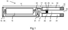
- Figure 1shows a pair of air inlets 17 provided at the intersection between the power supply portion 12 and the atomizer/liquid reservoir portion 14.
- a power supplypreferably a battery 18, an LED 20, control electronics 22 and optionally an airflow sensor 24 are provided within the cylindrical hollow tube power supply portion 12.
- the battery 18is electrically connected to the control electronics 22, which are electrically connected to the LED 20 and the airflow sensor 24.
- the LED 20is at the front end of the power supply portion 12, adjacent to the end cap 16 and the control electronics 22 and airflow sensor 24 are provided in the central cavity at the other end of the battery 18 adjacent the atomizer/liquid reservoir portion 14.
- the airflow sensor 24acts as a puff detector, detecting a user puffing or sucking on the atomizer/liquid reservoir portion 14 of the electronic cigarette 10.
- the airflow sensor 24can be any suitable sensor for detecting changes in airflow or air pressure, such as a microphone switch including a deformable membrane which is caused to move by variations in air pressure.
- the sensormay be a Hall element or an electro-mechanical sensor.
- the control electronics 22are also connected to an atomizer 26.
- the atomizer 26includes a heating coil 28 which is wrapped around a wick 30 extending across an air tube 32 forming a central passage passing through the atomizer/ liquid reservoir portion 14.
- the coil 28may be positioned anywhere in the atomizer 26 and may be transverse or parallel to the liquid reservoir 34.
- the wick 30 and heating coil 28do not completely block the air tube 32. Rather an air gap is provided on either side of the heating coil 28 enabling air to flow past the heating coil 28 and the wick 30.
- the atomizer 26may alternatively use other forms of heating elements, such as ceramic heaters, or fiber or mesh material heaters. Nonresistance heating elements such as sonic, piezo and jet spray may also be used in the atomizer 26 in place of the heating coil.
- the air tube 32is surrounded by a cylindrical liquid reservoir 34 with the ends of the wick 30 abutting or extending into the liquid reservoir 34.
- the wick 30may be a porous material such as a bundle of fiberglass fibers, with liquid in the liquid reservoir 34 drawn by capillary action from the ends of the wick 30 towards the central portion of the wick 30 encircled by the heating coil 28.
- the liquid reservoir 34may alternatively include wadding soaked in liquid which encircles the central passage 32 with the ends of the wick 30 abutting the wadding.
- the liquid reservoir 34may comprise a toroidal cavity arranged to be filled with liquid and with the ends of the wick 30 extending into the toroidal cavity.
- a mouthpiece 35 having an inhalation port 36is attached to the end of the atomizer/liquid reservoir portion 14 remote from the end cap 16.
- the mouth piece 35acts to enclose the end of the liquid reservoir 34 remote from the end cap 16 with the inhalation port 36 being an extension of the central passage formed by the air tube 32.
- the mouthpiece 35 and the atomizer/liquid reservoir portion 14may be configured to fit together by a friction push fit, a snap fit, or a bayonet attachment, magnetic fit, or screw threads.
- a usersucks on the electronic cigarette 10.
- Thiscauses air to be drawn into the electronic cigarette 10 via one or more air inlets, such as air inlets 17, and to be drawn through the air tube 32 towards the air inhalation port 36.
- the change in air pressure which arisesis detected by the airflow sensor 24, which generates an electrical signal that is passed to the control electronics 22.
- the control electronics 22activate the heating coil 28, which causes liquid present in the wick 30 to be vaporized creating an aerosol (which may comprise gaseous and liquid components) within the air tube 32.
- this aerosolis drawn through the air tube 32 and air inhalation port 36 and inhaled by the user.
- control electronics 22also activate the LED 20 causing the LED 20 to light up which is visible via the translucent end cap 16 mimicking the appearance of a glowing ember at the end of a conventional cigarette.
- the control electronics 22also activate the LED 20 causing the LED 20 to light up which is visible via the translucent end cap 16 mimicking the appearance of a glowing ember at the end of a conventional cigarette.
- liquid present in the wick 30is converted into an aerosol more liquid is drawn into the wick 30 from the liquid reservoir 34 by capillary action and thus is available to be converted into an aerosol through subsequent activation of the heating coil 28.
- the LED 20may be omitted.
- the airflow sensor 24may be placed adjacent the end cap 16 rather than in the middle of the electronic cigarette.
- the airflow sensor 24may be replaced with a switch which enables a user to activate the electronic cigarette manually rather than in response to the detection of a change in air flow or air pressure.
- the atomizermay have a heating coil in a cavity in the interior of a porous body soaked in liquid.
- aerosolis generated by evaporating the liquid within the porous body either by activation of the coil heating the porous body or alternatively by the heated air passing over or through the porous body.
- the atomizermay use a piezoelectric atomizer to create an aerosol either in combination or in the absence of a heater.
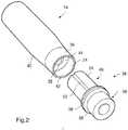
- Figure 2is a perspective view of a nozzle 38 of a liquid dispenser (with the liquid dispenser omitted) and the atomizer/liquid storage portion 14 of an electronic cigarette
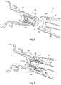
- Figures 3-5are cross sectional views of the nozzle 38 and an end of the atomizer/liquid storage portion 14 in an uncoupled, an intermediate and coupled configuration.
- the atomizer/liquid storage portion 14 of an electronic cigarette shown in the figuresis shown with the mouthpiece 35 removed.
- the illustrated features of the atomizer/liquid storage portion 14 of an electronic cigarettecomprise a mouthpiece port 39 and a body section 40.
- the mouthpiece port 39comprises a hollow section open at both ends and configured to receive an end of a mouthpiece 35 (not shown) in an aperture 42 at a first end thereof.
- a second aperture 44 at opposite end of mouthpiece port 39provides fluid communication between the mouthpiece port 39 and both the liquid reservoir 34 and the air tube 32 of the atomizer/liquid storage portion 14 of the electronic cigarette.
- the aperture 44is partly sealed by the end of the mouthpiece 35 to provide fluid communication with the air tube 32 only. This is to prevent liquid contained in liquid reservoir 34 from leaking from the liquid reservoir 34.
- the mouthpiece 35is removed from the mouthpiece port 39 of the atomizer/liquid storage portion 14 of the electronic cigarette, leaving the atomizer/liquid storage portion 14 of an electronic cigarette in the state as illustrated.
- the nozzle 38 of a liquid dispensercan be slid into the mouthpiece port 39 of the atomizer/liquid storage portion 14 of an electronic cigarette to undertake the re-filling process.
- the nozzle 38 in this embodimentcomprises a first 48 and a second 50 tubular section joined together. Together the first 48 and second tubular sections act to form a housing and define a liquid flow path through the nozzle 38.
- a groove 52is provided on the exterior wall 54 of the first section 48 of the nozzle 38.
- Flanges 56,58extend from the ends of the first section 48 and a second section 50 which abut each other which facilitates joining the sections, together allowing the first 48 and second 50 sections to be manufactured as separate units prior to assembly.
- the exterior wall 54 of the first section 48 of the nozzle 38is slidably engagable within the aperture 42 of the mouthpiece port 39 of the atomizer/liquid storage portion 14 other than the region of the wall 54 comprising the groove 52 which is recessed relative to the size of the aperture 42.
- FIG. 3shows a cross-sectional view of the nozzle 38
- a helical coil spring 60is inserted into the cavity of the second section 50 of the nozzle 38 and a plunger 62 extends through the middle of helical coil spring 60 so that shoulder 64 on the plunger 62 may contact an end 60a of the spring 60
- the plunger 62is inserted into the hollow cylindrical cavity 66 of first section 48 of the nozzle 38.
- the first section 48 and second section 50are connected together so that the spring 60 is partially compressed such that one end, 60a, abuts the shoulder 64 of the plunger 62 and the other end abuts an interior formation 68 of the nozzle 38 (in the illustrated case a formation on second section 50).
- the compression of the spring 60causes the plunger 62 to be biased against and abut a partially inwardly extending portion 72 of the first section 48 side wall.
- the exterior wall 54 of the first section 48 of the nozzle 38is configured to be in slidable engagement with a portion 74 of the inner wall of mouthpiece port 39 of the atomizer/liquid storage portion 14. Also shown is a thinner section 76 of the exterior wall 54 of the first section of the nozzle 38 which forms the bottom of groove 52 illustrated in figure 2 .
- Figure 4is a schematic illustration of the nozzle 38 partially inserted into the atomizer/liquid storage portion 14 of an electronic cigarette. Not all reference numerals are shown in this figure for clarity purposes.
- the slidable engagement of the outer wall 52 of the first section 48 with the portion 74 of the inner wall of the mouthpiece port 39 of the atomizer/liquid storage portion 14is clearly illustrated. Additionally, groove 52 can be seen to be in the process of being formed between the thinner portion of the wall 54 and the corresponding portion 74 of the inner wall of mouthpiece port 39 of the atomizer/liquid storage portion 14. Advancing the nozzle 38 toward the atomizer/liquid storage portion 14 in a direction indicated by arrow A will bring the nozzle 38 and the atomizer/liquid storage portion 14 closer to full engagement.
- Figure 5is an illustration of the nozzle 38 and atomizer/liquid storage portion 14 fully engaged with each other.
- the travel of first section 48 of the nozzle 38 into the mouthpiece port 39 of the atomizer/liquid storage portion 14 of the electronic cigarette in the direction indicated by arrow Acauses a sealing surface 78 of plunger 62 to come into contact with the end of the air tube 32 of the atomizer/liquid storage portion 14 of the electronic cigarette.
- groove 52extends along wall 54 to form a gas pathway from groove 52 into the liquid reservoir 34.
- the gas pathwayprovides a venting mechanism for air to escape from a reservoir being filled with a liquid but also may provide for the ingress of air into a bottle from which the liquid is being supplied to the reservoir.
- the sealing surface 78 of the plunger 62engages with and blocks the open end of the air tube 32.
- the plunger 62blocks the open end of the air tube 32 and prevents liquid from entering the air tube 32 and hence prevents liquid from flooding the atomizer 26.
- a central portion of the sealing surface 78is indented so that when the plunger 62 engages the end of the air tube 32, the air tube 32 enters the recess defined by the indentation.
- a re-filling processwill be conducted with the nozzle 38 and atomizer/liquid storage portion 14 of an electronic cigarette substantially vertical with the nozzle 38 above the atomizer/liquid storage portion 14 of an electronic cigarette.
- liquid to be dispensedwill travel in the direction of arrow A under the influence of gravity down through the nozzle 38 and into the liquid reservoir 34 of the atomizer/liquid storage portion 14 of the electronic cigarette.
- Figure 6shows the nozzle 38 and atomizer/liquid storage portion 14 of an electronic cigarette in the uncoupled configuration and figure 7 shows the nozzle 38 and atomizer/liquid storage portion 14 of an electronic cigarette in the coupled configuration.
- the nozzle 38is disposed in the neck of a liquid dispenser bottle 80.
- the plunger 62 of nozzle 38is in a closed configuration. With the nozzle 38 inserted in the mouthpiece port 39 of the atomizer/liquid storage portion 14 (i.e.
- Gas displaced from the liquid reservoir 34 as a result of the liquid being addedis vented from the liquid reservoir 34 via a gas pathway formed by groove 52.
- Gas flow from the liquid reservoir 34 of atomizer/liquid storage portion 14 of an electronic cigaretteis illustrated in figure 7 by way of arrows 84.
- the displaced gasmay, for example, be vented to atmosphere (as shown in figure 7 ).
- the groove 52may be configured to form a gas pathway for venting the displaced gas into the dispenser bottle 80.
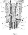
- FIGS 8 and 9are cross-sectional views of a nozzle 38 of a liquid dispenser 80 attached to a mouthpiece port 39 at the end of the atomizer/liquid storage portion 14 of an electronic cigarette in a first and a second configuration.
- a plunger 62is provided within the nozzle 38 with the plunger 62 being biased in the position illustrated in Figure 8 by a coil spring 60.
- portion of the plunger 62rests against and compresses a seal 86 attached to the plunger 62 which acts to block a liquid flow path and prevent liquid from flowing out of a dispenser bottle 80 to which the nozzle 38 is attached.
- a screw thread 88is provided on the inside wall of the mouthpiece port 39 at the end of the atomizer/liquid storage portion 14 of an electronic cigarette arranged to match with a corresponding screw thread on a mouthpiece (not shown) when the electronic cigarette is in use.
- a matching screw thread 90is provided on the exterior wall at the tip of the nozzle 38.
- a further seal 92is provided on the nozzle 38 adjacent the end of the screw thread 90 remote from the tip of the nozzle 38.
- Figure 9illustrates the nozzle 38 fully engaged into the mouthpiece port 39 with the plunger 62 in an open configuration.
- the seal 86 provided on the plunger 62is lifted away from the flow path through the nozzle 38 and therefore ceases to block the flow path and permits liquid to flow from the dispenser 80 into the liquid reservoir as indicted by the arrow on the left hand side of Figure 9 .
- the relative lengths and arrangement of the plunger 62, air tube 32 and screw threads 88,90are such that when the screw thread 90 of the nozzle 38 initially engages into the screw thread on the mouthpiece port 38, the end surface of the plunger 62 does not rest against the end of the air tube 32. Rather it is only when the screw threads 88, 90 are tightened to the extent which compresses the seal 92 (such as is illustrated in figure 9 ) that the plunger 62 reaches the end of the air tube 32. When this occurs as in the previous embodiment this pushes the plunger 62 against the coil spring 60 and opens a liquid flow path from the liquid dispenser 80 into the liquid reservoir 34 adjacent the air tube 32.
- an air vent 94separate from the liquid flow path is provided in the nozzle 38 enabling air to vent out of the liquid reservoir 34 as liquid is transferred into the liquid reservoir 34 from the liquid dispenser 80.
- the air flow path via the air vent 94is indicated by the arrow on the right of the figure.
- the present embodimenthas a number of advantages over the first embodiment.
- Refilling an electronic cigarette with liquid for atomizationinvolves a number of distinct stages. First the mouth piece 35 at the end of the electronic cigarette is removed, revealing the end of the liquid reservoir 34. Then a liquid dispenser 80 is utilized to fill the liquid reservoir 34. The liquid dispenser 80 is then removed and then finally the mouthpiece 35 is replaced.
- refillable electronic cigaretteshave been described in which a dispenser nozzle 38 is arranged to dispense liquid only when the nozzle 38 is engaged with the liquid reservoir 34 of an electronic cigarette. In the previous embodiments this is achieved by having the operation of the liquid dispenser activated by the engagement of a plunger 62 with the end of an air tube 32 of an electronic cigarette. This addresses the problem of accidental discharge of liquid from the liquid dispenser 80 other than when the liquid dispenser 80 is directed to filling an electronic cigarette.
- liquid dispenser 80 and a liquid reservoir 34are sealed during a refilling operation it is possible for liquid to leak from the liquid reservoir 34 either prior to attachment of the liquid dispenser 80 (if some residual liquid is present in the liquid reservoir 34 when the electronic cigarette is being refilled) or alternatively immediately after the liquid dispenser 80 has been detached from the electronic cigarette and prior to the reattachment of the mouthpiece 35.
- liquid reservoir 34In some electronic cigarettes, this problem is avoided by providing wadding, a sponge or other absorbent material within the liquid reservoir 34.
- the liquid reservoir 34is in the form of an empty cavity or tank.
- a third embodiment of the present inventionwill now be described in which the leakage of liquid for atomization from an electronic cigarette prior to or immediately after refilling the electronic cigarette and when the mouthpiece port 39 of the electronic cigarette is not enclosed by the presence of a mouthpiece 35 is prevented.
- Figure 10is a schematic cross-sectional illustration of an atomizer and a liquid reservoir for an electronic cigarette.
- a membrane 96provided at the end of the liquid reservoir 34 adjacent the end 98 of the air tube 32
- the structure of the atomizer/liquid reservoiris identical to the atomizer/liquid reservoir portion 14 of figure 1 and corresponding features have been identified with the same reference numerals as were used in relation to describing the atomizer/liquid reservoir portion 14 of figure 1 .
- FIG 11is a plan view of the membrane 96.
- the membranecomprises a circular disc of a rubber or other flexible material.
- a hole 100is provided a the center of the disc with the hole corresponding in size with the size of the air tube 32 and the diameter of the disc corresponding in size to the opening at the end of the liquid reservoir 34.
- the membraneWhen positioned within the atomizer/liquid reservoir portion 14 the membrane acts to enclose the open end of the liquid reservoir 34 with the end 98 of the air tube 32 protruding through the hole 100 at the center of the disc.
- slit valves 102are provided within the membrane 96. When the membrane 96 is in the position indicated in figure 10 , these slit valves 102 will be in a closed configuration as is illustrated in Figure 11 . In this configuration the membrane acts as a barrier to prevent any liquid from within the liquid reservoir 34 from exiting the liquid reservoir 34.
- Figure 12is a schematic cross sectional illustration of a nozzle 38 of a liquid dispenser engaging the membrane 96 of Figure 11 .
- the nozzle 38contains a plunger 62 which is biased by a spring 60 into a closed configuration in which liquid flow via the nozzle 38 is blocked.
- the plunger 62engages the end 96 of the air tube 32, this presses the plunger 62 against the spring 60 and opens a liquid flow path through the nozzle 38.
- the plunger 62caps the end 98 of the air tube 32 and prevents liquid from entering the air tube 32.
- the nozzle 38presses against the membrane 96 causing the membrane 96 to deform.
- Figure 13is a plan view of the membrane of figure 11 when the membrane 96 is deformed by the nozzle 38 pressing against the membrane 96.
- the membrane 96adopts an open configuration in which the slit valves 102 adopt an open configuration as is illustrated in the figure.
- liquid passing via the fluid flow path within the nozzle 38can enter the liquid reservoir 34 via the open slit valves 102.
- a plunger 62has been described as capping or blocking the end of an air tube 32 of an electronic cigarette, it will be appreciated that various alternative means for preventing liquid from entering the air tube 32 might be utilised. Thus for example rather than completely covering the end of the air tube, the plunger 62 might be shaped to deflect liquid away from the tube.
- the plunger 62has been described as having, according to the invention, a recess for capping the air tube 32 whereas a plunger 62 with a flat end surface is shown in the second embodiment.
- This flat end surface solutionis not in accordance with the invention. will be appreciated that in other solutions the end of the plunger might have a protrusion configured to enter into the air tube 32 to block the tube.
- screw threads 88were provided on the interior of a mouthpiece port 39 and on the exterior of a nozzle 39. It will be appreciated that other configurations of screw thread might be utilised. Thus for example a screw thread might be provided on the exterior or the mouthpiece port and a corresponding screw thread might be provided on an interior wall extending from the end of the nozzle 38.
- a refilling systemhas been described in which a liquid dispenser 80 is attached to a liquid reservoir 34 of an electronic cigarette via a pair of screw threads 88,90. It will be appreciated that other forms of connection such as magnetic, friction fit or push fit or bayonet fittings could be utilised instead.
- a seal 92could be provided in the absence of any screw threads with arrangement of the seal 92 and the distances between the plunger 62 and the end of an air tube 32 being such that the seal 92 is caused be compressed prior to the plunger 62 being activated to open a liquid flow path between a liquid dispenser 80 and a liquid reservoir 34.
- a spring 60to provide the compression force on the plunger 62 to bias it into the closed position
- alternative means of compressioncould be used.
- One examplewould be a flexible rubber material which is mildly compressed to bias the plunger 62, but with increased compression of the rubber material, the plunger 62 would move to the open position.
- the rubber materialcould be assembled to be in tension when it is connected from the plunger 62 to the nozzle 38, and pushing/screwing the nozzle onto the atomiser results in an increase in tension to open the plunger.
- an air vent 94has been described as enabling air to be vented to atmosphere, in other embodiments the air vent 94 could be connected to a low pressure air reservoir such that air is caused to be sucked out of the liquid reservoir 34. In such embodiments low pressure air reservoir might be activated by the operation of the plunger 62 so that air is sucked from the liquid reservoir 34 as liquid is delivered from the liquid dispenser.
- nozzles 38 containing spring biased plungers 62have been described as being attached to liquid dispensing bottles, it will be appreciated that such nozzles could be integrally formed with such dispensers or alternative could be attached to such dispensers. It will also be appreciated that other forms of liquid dispenser other than a bottle might be used to store liquid prior to transfer to a liquid reservoir 34 of an electronic cigarette or other electronic smoking device.
- a refilling systemin which the flow of liquid is inhibited prior to a nozzle 38 being attached to the mouthpiece port 39 of an electronic cigarette by virtue of the relative arrangement of a plunger 62, an air tube 32 and the screw threads 80,90 provided on a nozzle 38 of a dispensing device and on the mouthpiece port 39 of an electronic cigarette.
- other meanscould be provided to inhibit fluid flow so as to avoid accidental discharge of liquid.
- a protrusionmight be provided on the exterior of the plunger 62 with a corresponding recess being provided within the cavity containing the plunger 62 (or vice versa) where the recess was blocked and user action was required remove the blockage (e.g. by depressing a button or twisting the device).
- a benefit of such a systemwould be that two actions (e.g. attaching the dispenser to the mouthpiece port 39 and depressing a button etc.) would be required to result in liquid being dispensed.
- a refilling systemhas been described in which a liquid dispenser 80 is attached to a liquid reservoir 34 of an electronic cigarette via a pair of screw threads 88,90. It will be appreciated that other forms of connection such as magnetic, friction fit or push fit or bayonet fittings could be utilised instead.
- a membrane 96 with four slit valvesis illustrated, it will be appreciated that a membrane 96 with more or fewer slit valves 102 might be used. Similarly it will be appreciated that the arrangement of the slit valves 102 may differ from the arrangement illustrated in the figures.
Landscapes
- Engineering & Computer Science (AREA)
- Mechanical Engineering (AREA)
- Health & Medical Sciences (AREA)
- General Health & Medical Sciences (AREA)
- Life Sciences & Earth Sciences (AREA)
- Veterinary Medicine (AREA)
- Anesthesiology (AREA)
- Biomedical Technology (AREA)
- Heart & Thoracic Surgery (AREA)
- Hematology (AREA)
- Public Health (AREA)
- Animal Behavior & Ethology (AREA)
- Ceramic Engineering (AREA)
- Bioinformatics & Cheminformatics (AREA)
- Pulmonology (AREA)
- Chemical & Material Sciences (AREA)
- Dispersion Chemistry (AREA)
- Containers And Packaging Bodies Having A Special Means To Remove Contents (AREA)
- Nozzles (AREA)
Description
- The present invention relates generally to electronic smoking devices and in particular electronic cigarettes. More specifically the present invention relates to filling systems for refilling the reservoir of an electronic smoking device with liquid for vaporization.
- An electronic smoking device is an electronic device that permits the user to simulate the act of smoking by producing an aerosol mist or vapor that is drawn into the lungs through the mouth and then exhaled. The inhaled aerosol mist or vapor typically bears nicotine and/or other flavorings without the odor and health risks associated with traditional smoking and tobacco products. In use, a user experiences a similar satisfaction and physical sensation to those experienced from a traditional smoking or tobacco product, and exhales an aerosol mist or vapor of similar appearance to the smoke exhaled when using such traditional smoking or tobacco products.
- An electronic smoking device, such as an electronic cigarette, typically has a housing accommodating an electric power source (e.g. a single use or rechargeable battery, electrical plug, or other power source), and an electrically operable atomizer. The atomizer vaporizes or atomizes liquid supplied from a reservoir and provides vaporized or atomized liquid as an aerosol which is extracted from the electronic smoking device via an air tube and a mouthpiece by a user sucking on the mouthpiece.
- The reservoir may be either a replaceable or refillable container that is coupled to, or located in, the main body of the electronic smoking device and that is typically made of a resilient plastic material such as high-density polypropylene. The reservoir may contain a wicking material in which the liquid is stored or alternatively may just be a storage space without any wicking material. Once the replaceable or refillable reservoir is emptied it must either be replaced or refilled.
- Control electronics control the activation of the atomizer. In some electronic cigarettes, an airflow sensor is provided within the electronic smoking device, which detects a user puffing on the device (e.g., by sensing an under-pressure or an air flow pattern through the device). The airflow sensor indicates or signals the puff to the control electronics to power up the device and generate vapor. In other electronic cigarettes, a switch is used to power up the electronic cigarette to generate a puff of vapor.
- The ingredients of the liquid for producing the aerosol mist or vapor in smoking-substitute devices vary widely, but typically include water and flavorings in a propylene glycol and/or glycerol base. Nicotine may also be included in solutions intended to fulfil a nicotine replacement role, without the harmful products associated with tobacco smoke.
- Typically, electronic cigarettes are refilled by removing a mouthpiece from one end of the electronic cigarette to reveal the open end of the refillable reservoir. Liquid for atomization is then dispensed from a dispenser that commonly resembles the small dropper bottles used for dispensing eye drops by dripping liquid from the outlet liquid-dispensing tip of the dispenser into the revealed open end of the reservoir by squeezing the walls of the dispenser.
- Existing liquid dispensing systems suffer from a number of drawbacks.
- Frequently electronic smoking devices, particularly electronic cigarettes have approximately the same size and shape as a conventional cigarette, typically about 100 mm with a 7.5 mm diameter, although lengths may range from 70 to 150 or 178 mm, and diameters from 5 to 28 mm. This presents a relatively small target for a user when refilling the device.
- Furthermore, in many designs of electronic cigarette, the air tube providing a gas passage way between the atomizer and the mouthpiece is located in the center of the reservoir. In such designs, often it is important when refilling the liquid reservoir for users to avoid dripping liquid into the air tube as if such liquid passes down the air tube into the atomizer this floods the atomizer and temporarily stops the device from working. When the device is then operated to clear the misplaced liquid, this often results in leakage as the misplaced liquid finds its way out of the atomizer through the air passage. Clearing the air passage is also often accompanied by a "gurgling" sound and sensation which users find unpleasant. Having to avoid dripping liquid down the air tube further reduces the cross-section of the available target for dripping liquid into the reservoir.
- Difficulties in refilling an electronic smoking device may cause users to miss the reservoir causing their fingers holding the electronic smoking device to come into contact with the liquid for atomization. Further liquid may spill from the reservoir prior to the mouthpiece of the device being re-attached closing the open end of the reservoir. Often liquid for atomization is relatively greasy and is impregnated with flavors which makes coming into contact unpleasant and undesirable as the liquid needs to be washed off and odors from the liquid may be retained on the hands. Further there is a risk that users may accidentally ingest the liquid if the liquid is not washed off.
WO2014195859A2 relates to an electronic cigarette with improved safety.GB921899A KR20150009908A WO2014167515A1 discloses an electronic smoking substitutive device, commonly known as electronic cigarette.EP3129089 (Art. 54(3) EPC) discloses an apparatus for transfering E-liquid into the chamber of an electronic vaporization device. - In accordance with one aspect of the present invention there is provided a nozzle for a liquid dispensing system for transferring liquid into a liquid reservoir of an electronic smoking device. A plunger is provided within a liquid flow path through the nozzle with the plunger being moveable between an open position in which liquid may flow through the liquid flow path and a closed position in which liquid flow through the liquid flow path is restricted with the plunger being biased towards the closed position. The nozzle and the plunger are configured so that when the nozzle is inserted into an engagement position within an opening providing access to a liquid reservoir which contains an air tube for extracting vapour from an electronic smoking device, the plunger engages with the air tube and is moved from the closed position to the open position. When located in an engagement position, the plunger diverts liquid flowing via the flow path through said nozzle into the liquid reservoir and away from the air tube, wherein said plunger has an indentation operable to receive the air tube of the electronic cigarette when said nozzle is in the engagement position.
- In some embodiments said plunger is configured so that when the nozzle is inserted into the engagement position within the opening providing access to the liquid reservoir of the electronic smoking device which contains the air tube for extracting vapour from the electronic smoking device, the plunger engages with said air tube and is moved from said closed position to said open position, the plunger in said engagement position being such as to block said air tube and prevent liquid flowing via the flow path through said nozzle from entering said air tube.
- In some embodiments a sealing member is mounted on said plunger, wherein said sealing member seals said liquid flow path when said plunger is in said closed position.
- In some embodiments a sealing member is mounted on said nozzle wherein said sealing member is configured to seal an opening providing access to a liquid reservoir which contains an air tube for extracting vapour from the electronic smoking device when the nozzle is inserted into an engagement position within said opening.
- In some embodiments said nozzle is configured so that said sealing member seals the opening prior to the air tube of the electronic smoking device engaging with the plunger and moving the plunger into an open position.
- In some embodiments a screw thread, bayonet, magnetic, friction fit, push fit or other type of fitting is provided on said nozzle which matches a corresponding screw thread, bayonet, magnetic, friction fit, push fit or other type of fitting at the opening providing access to the liquid reservoir.
- In some embodiments the screw thread, bayonet, magnetic, friction fit, push fit or other type of fitting is positioned on said nozzle so that if the nozzle is attached to a device having a matching screw thread, bayonet, magnetic, friction fit, push fit or other type of fitting, said screw threads, screw thread, bayonet, magnetic, friction fit, push fit or other type of fitting engage each other before the plunger engages with said air tube within said opening.
- In some embodiments the nozzle further comprises an air vent enabling air to vent from the liquid reservoir when the nozzle is in the engagement position within an opening within the electronic smoking device. In some embodiments said air vent is connected to a low pressure reservoir arranged to extract air from the liquid reservoir when said nozzle is in the engagement position.
- In some embodiments said low pressure reservoir is activated by movement of said plunger to extract air from the liquid reservoir when said plunger is in said open position.
- According to the invention, said plunger has an indentation operable to receive the air tube of the electronic cigarette when said nozzle is in the engagement position.
- In some embodiments said plunger is biased towards said closed position by a spring or movement of the plunger from said closed position to said open position compresses or stretches a resilient material, the compression or the stretching of said resilient material biasing said plunger towards said closed position.
- In accordance with another aspect of the present invention, a liquid supply system for an electronic smoking device is provided comprising: a liquid dispenser; and the nozzle in accordance with the one aspect of the present invention.
- In accordance with one further aspect of the present invention there is provided the combination defined in claim 13.
- In some embodiments of this combination said opening is a mouthpiece port operable to receive a mouthpiece configured for extracting vapour via said air tube.
- In some embodiments of this combination a membrane having one or more slit valves is provided adjacent the end of the air tube accessible via said opening, wherein when said nozzle is in said engagement position, said membrane is caused to be deformed opening said slit valves and permitting liquid to flow into said liquid reservoir.
- In accordance with yet another aspect of the present invention, a method of refiling a liquid reservoir of an electronic cigarette is provided comprising: providing a liquid supply system in accordance with the another aspect of the present invention; inserting a nozzle into an opening providing access to the liquid reservoir wherein the plunger of the nozzle engages with an air tube accessible via the opening and is moved from a closed position to an open position, the plunger when engaged being such as to divert liquid flowing through the nozzle into the liquid reservoir and away from the air tube.
- In some embodiments a screw thread, bayonet, magnetic, friction fit, push fit or other type of fitting is provided on said nozzle which matches a corresponding screw thread, bayonet, magnetic, friction fit, push fit or other type of fitting at the opening providing access to the liquid reservoir, the screw threads, bayonet, magnetic, friction fit, push fit or other type of fitting being positioned on said nozzle so that when the nozzle is inserted into the opening said screw threads, bayonet, magnetic, friction fit, push fit or other type of fitting engage each other before the plunger engages with an air tube within said opening.
- In some embodiments a seal is provided on said nozzle wherein said seal seals said opening when said nozzle is inserted into said opening prior to the plunger engaging the air tube within said opening.
- In some embodiments a membrane having one or more slit valves is provided adjacent the end of the air tube accessible via said opening, wherein when said nozzle is in said engagement position, said membrane is caused to be deformed opening said slit valves and permitting liquid to flow into said liquid reservoir.
- The characteristics, features and advantages of this invention and the manner in which they are obtained as described above, will become more apparent and be more clearly understood in connection with the following description of exemplary embodiments, which are explained with reference to the accompanying drawings.
- In the drawings, same element numbers indicate same elements in each of the views:
Figure 1 is a schematic cross-sectional illustration of an exemplary electronic cigarette with a refillable liquid reservoir;Figure 2 is a perspective view of a nozzle of a liquid dispenser in accordance with an embodiment of the present invention and an atomizer/liquid storage portion of an electronic cigarette;Figure 3 is a cross-sectional view of the nozzle of a liquid dispenser and the end of the atomizer/liquid storage portion of an electronic cigarette ofFigure 2 in an uncoupled configuration;Figure 4 is a cross-sectional view of the nozzle of a liquid dispenser and the end of the atomizer/liquid storage portion of an electronic cigarette ofFigure 2 in an intermediate stage between an uncoupled configuration and a coupled configuration;Figure 5 is a cross-sectional view of the nozzle of a liquid dispenser and the end of the atomizer/liquid storage portion of an electronic cigarette ofFigure 2 in a coupled configuration;Figure 6 is another cross-sectional view illustrating the nozzle of the liquid dispenser and the end of the atomizer/liquid storage portion of an electronic cigarette ofFigure 2 in an uncoupled configuration;Figure 7 is a further cross-sectional view illustrating the nozzle of the liquid dispenser and the end of the atomizer/liquid storage portion of an electronic cigarette ofFigure 2 in a coupled configuration;Figure 8 is a cross-sectional view of a nozzle of a liquid dispenser of a second embodiment connected into a mouthpiece port at the end of the atomizer/liquid storage portion in a first configuration;Figure 9 is a cross-sectional view of the nozzle of the liquid dispenser offigure 8 inserted connected to a mouthpiece port at the end of the atomizer/liquid storage portion in a second configuration;Figure 10 is a schematic cross-sectional illustration of an atomizer and liquid reservoir for an electronic cigarette;Figure 11 is a plan view of a membrane for enclosing a liquid reservoir for an electronic cigarette;Figure 12 is a schematic cross sectional illustration of a nozzle of a liquid dispenser engaging the membrane ofFigure 11 ;Figure 13 is a plan view of the membrane offigure 11 in an open configuration.- Prior to describing refilling systems in accordance with embodiments of the present invention, an exemplary electronic smoking device in the form of an electronic cigarette of the type which might be refilled using the described systems will first be described with reference to
Figure 1 which is a schematic cross-sectional illustration of an exemplary electronic cigarette. - As is shown in
Figure 1 , anelectronic cigarette 10 typically has a housing comprising a cylindrical hollow tube having anend cap 16. The cylindrical hollow tube may be a single-piece or a multiple-piece tube. InFigure 1 , the cylindrical hollow tube is shown as a two-piece structure having apower supply portion 12 and an atomizer/liquid reservoir portion 14. Together thepower supply portion 12 and the atomizer/liquid reservoir portion 14 form a cylindrical tube which can be approximately the same size and shape as a conventional cigarette, typically about 100 mm with a 7.5 mm diameter, although lengths may range from 70 to 150 or 178 mm, and diameters from 5 to 28 mm. - The
power supply portion 12 and atomizer/liquid reservoir portion 14 are typically made of metal, e.g. steel or aluminum, or of hardwearing plastic and act together with theend cap 16 to provide a housing to contain the components of theelectronic cigarette 10. Thepower supply portion 12 and an atomizer/liquid reservoir portion 14 may be configured to fit together by a friction push fit, a snap fit, or a bayonet attachment, magnetic fit, or screw threads. - The atomizer/
liquid storage portion 14 of an electronic cigarette may be removable and/or replaceable from a body portion of anelectronic cigarette 10, or may be integrally formed with the body portion of theelectronic cigarette 10. - The
end cap 16 is provided at the front end of thepower supply portion 12. Theend cap 16 may be made from translucent plastic or other translucent material to allow a light-emitting diode (LED) 20 positioned near the end cap to emit light through the end cap. Theend cap 16 can be made of metal or other materials that do not allow light to pass. - An air inlet may be provided in the
end cap 16, at the edge of the inlet next to the cylindrical hollow tube, anywhere along the length of the cylindrical hollow tube, or at the connection of thepower supply portion 12 and the atomizer/liquid reservoir portion 14.Figure 1 shows a pair ofair inlets 17 provided at the intersection between thepower supply portion 12 and the atomizer/liquid reservoir portion 14. - A power supply, preferably a
battery 18, anLED 20,control electronics 22 and optionally anairflow sensor 24 are provided within the cylindrical hollow tubepower supply portion 12. Thebattery 18 is electrically connected to thecontrol electronics 22, which are electrically connected to theLED 20 and theairflow sensor 24. In this example theLED 20 is at the front end of thepower supply portion 12, adjacent to theend cap 16 and thecontrol electronics 22 andairflow sensor 24 are provided in the central cavity at the other end of thebattery 18 adjacent the atomizer/liquid reservoir portion 14. - The
airflow sensor 24 acts as a puff detector, detecting a user puffing or sucking on the atomizer/liquid reservoir portion 14 of theelectronic cigarette 10. Theairflow sensor 24 can be any suitable sensor for detecting changes in airflow or air pressure, such as a microphone switch including a deformable membrane which is caused to move by variations in air pressure. Alternatively the sensor may be a Hall element or an electro-mechanical sensor. - The
control electronics 22 are also connected to anatomizer 26. In the example shown, theatomizer 26 includes aheating coil 28 which is wrapped around awick 30 extending across anair tube 32 forming a central passage passing through the atomizer/liquid reservoir portion 14. Thecoil 28 may be positioned anywhere in theatomizer 26 and may be transverse or parallel to theliquid reservoir 34. Thewick 30 andheating coil 28 do not completely block theair tube 32. Rather an air gap is provided on either side of theheating coil 28 enabling air to flow past theheating coil 28 and thewick 30. Theatomizer 26 may alternatively use other forms of heating elements, such as ceramic heaters, or fiber or mesh material heaters. Nonresistance heating elements such as sonic, piezo and jet spray may also be used in theatomizer 26 in place of the heating coil. - The
air tube 32 is surrounded by acylindrical liquid reservoir 34 with the ends of thewick 30 abutting or extending into theliquid reservoir 34. Thewick 30 may be a porous material such as a bundle of fiberglass fibers, with liquid in theliquid reservoir 34 drawn by capillary action from the ends of thewick 30 towards the central portion of thewick 30 encircled by theheating coil 28. - The
liquid reservoir 34 may alternatively include wadding soaked in liquid which encircles thecentral passage 32 with the ends of thewick 30 abutting the wadding. In other embodiments theliquid reservoir 34 may comprise a toroidal cavity arranged to be filled with liquid and with the ends of thewick 30 extending into the toroidal cavity. - A
mouthpiece 35 having aninhalation port 36 is attached to the end of the atomizer/liquid reservoir portion 14 remote from theend cap 16. Themouth piece 35 acts to enclose the end of theliquid reservoir 34 remote from theend cap 16 with theinhalation port 36 being an extension of the central passage formed by theair tube 32. Themouthpiece 35 and the atomizer/liquid reservoir portion 14 may be configured to fit together by a friction push fit, a snap fit, or a bayonet attachment, magnetic fit, or screw threads. - In use, a user sucks on the
electronic cigarette 10. This causes air to be drawn into theelectronic cigarette 10 via one or more air inlets, such asair inlets 17, and to be drawn through theair tube 32 towards theair inhalation port 36. The change in air pressure which arises is detected by theairflow sensor 24, which generates an electrical signal that is passed to thecontrol electronics 22. In response to the signal, thecontrol electronics 22 activate theheating coil 28, which causes liquid present in thewick 30 to be vaporized creating an aerosol (which may comprise gaseous and liquid components) within theair tube 32. As the user continues to suck on theelectronic cigarette 10, this aerosol is drawn through theair tube 32 andair inhalation port 36 and inhaled by the user. At the same time thecontrol electronics 22 also activate theLED 20 causing theLED 20 to light up which is visible via thetranslucent end cap 16 mimicking the appearance of a glowing ember at the end of a conventional cigarette. As liquid present in thewick 30 is converted into an aerosol more liquid is drawn into thewick 30 from theliquid reservoir 34 by capillary action and thus is available to be converted into an aerosol through subsequent activation of theheating coil 28. - Of course, in addition to the above description of the structure and function of a typical
electronic cigarette 10, variations also exist. For example, theLED 20 may be omitted. Theairflow sensor 24 may be placed adjacent theend cap 16 rather than in the middle of the electronic cigarette. Theairflow sensor 24 may be replaced with a switch which enables a user to activate the electronic cigarette manually rather than in response to the detection of a change in air flow or air pressure. - Different types of atomizers may be used. Thus for example, the atomizer may have a heating coil in a cavity in the interior of a porous body soaked in liquid. In this design aerosol is generated by evaporating the liquid within the porous body either by activation of the coil heating the porous body or alternatively by the heated air passing over or through the porous body. Alternatively the atomizer may use a piezoelectric atomizer to create an aerosol either in combination or in the absence of a heater.
- A first embodiment of the present invention will now be described with reference to
Figure 2 which is a perspective view of anozzle 38 of a liquid dispenser (with the liquid dispenser omitted) and the atomizer/liquid storage portion 14 of an electronic cigarette, andFigures 3-5 which are cross sectional views of thenozzle 38 and an end of the atomizer/liquid storage portion 14 in an uncoupled, an intermediate and coupled configuration. - The atomizer/
liquid storage portion 14 of an electronic cigarette shown in the figures is shown with themouthpiece 35 removed. The illustrated features of the atomizer/liquid storage portion 14 of an electronic cigarette comprise amouthpiece port 39 and abody section 40. Themouthpiece port 39 comprises a hollow section open at both ends and configured to receive an end of a mouthpiece 35 (not shown) in anaperture 42 at a first end thereof. Asecond aperture 44 at opposite end ofmouthpiece port 39 provides fluid communication between themouthpiece port 39 and both theliquid reservoir 34 and theair tube 32 of the atomizer/liquid storage portion 14 of the electronic cigarette. When amouthpiece 35 is located within themouthpiece port 39, theaperture 44 is partly sealed by the end of themouthpiece 35 to provide fluid communication with theair tube 32 only. This is to prevent liquid contained inliquid reservoir 34 from leaking from theliquid reservoir 34. - During a re-filling process, the
mouthpiece 35 is removed from themouthpiece port 39 of the atomizer/liquid storage portion 14 of the electronic cigarette, leaving the atomizer/liquid storage portion 14 of an electronic cigarette in the state as illustrated. - With the atomizer/
liquid storage portion 14 of an electronic cigarette in this state, thenozzle 38 of a liquid dispenser can be slid into themouthpiece port 39 of the atomizer/liquid storage portion 14 of an electronic cigarette to undertake the re-filling process. - Referring first to
figure 2 , which shows thenozzle 38 of a liquid dispenser (the liquid dispenser itself is not shown infigure 2 ) prior to location within themouthpiece port 39 of the atomizer/liquid storage portion 14, thenozzle 38 in this embodiment comprises a first 48 and a second 50 tubular section joined together. Together the first 48 and second tubular sections act to form a housing and define a liquid flow path through thenozzle 38. - A
groove 52 is provided on theexterior wall 54 of thefirst section 48 of thenozzle 38.Flanges first section 48 and asecond section 50 which abut each other which facilitates joining the sections, together allowing the first 48 and second 50 sections to be manufactured as separate units prior to assembly. - The
exterior wall 54 of thefirst section 48 of thenozzle 38 is slidably engagable within theaperture 42 of themouthpiece port 39 of the atomizer/liquid storage portion 14 other than the region of thewall 54 comprising thegroove 52 which is recessed relative to the size of theaperture 42. - Turning now to
Figure 3 which shows a cross-sectional view of thenozzle 38, ahelical coil spring 60 is inserted into the cavity of thesecond section 50 of thenozzle 38 and aplunger 62 extends through the middle ofhelical coil spring 60 so thatshoulder 64 on theplunger 62 may contact anend 60a of thespring 60 Theplunger 62 is inserted into the hollowcylindrical cavity 66 offirst section 48 of thenozzle 38. - As can be seen in
Figure 3 , thefirst section 48 andsecond section 50 are connected together so that thespring 60 is partially compressed such that one end, 60a, abuts theshoulder 64 of theplunger 62 and the other end abuts aninterior formation 68 of the nozzle 38 (in the illustrated case a formation on second section 50). The compression of thespring 60 causes theplunger 62 to be biased against and abut a partially inwardly extendingportion 72 of thefirst section 48 side wall. Theexterior wall 54 of thefirst section 48 of thenozzle 38 is configured to be in slidable engagement with aportion 74 of the inner wall ofmouthpiece port 39 of the atomizer/liquid storage portion 14. Also shown is athinner section 76 of theexterior wall 54 of the first section of thenozzle 38 which forms the bottom ofgroove 52 illustrated infigure 2 . Figure 4 is a schematic illustration of thenozzle 38 partially inserted into the atomizer/liquid storage portion 14 of an electronic cigarette. Not all reference numerals are shown in this figure for clarity purposes. The slidable engagement of theouter wall 52 of thefirst section 48 with theportion 74 of the inner wall of themouthpiece port 39 of the atomizer/liquid storage portion 14 is clearly illustrated. Additionally, groove 52 can be seen to be in the process of being formed between the thinner portion of thewall 54 and the correspondingportion 74 of the inner wall ofmouthpiece port 39 of the atomizer/liquid storage portion 14. Advancing thenozzle 38 toward the atomizer/liquid storage portion 14 in a direction indicated by arrow A will bring thenozzle 38 and the atomizer/liquid storage portion 14 closer to full engagement.Figure 5 is an illustration of thenozzle 38 and atomizer/liquid storage portion 14 fully engaged with each other. As can be seen, the travel offirst section 48 of thenozzle 38 into themouthpiece port 39 of the atomizer/liquid storage portion 14 of the electronic cigarette in the direction indicated by arrow A causes a sealingsurface 78 ofplunger 62 to come into contact with the end of theair tube 32 of the atomizer/liquid storage portion 14 of the electronic cigarette. This forces theplunger 62 back againstspring 60. It should be noted thatgroove 52 extends alongwall 54 to form a gas pathway fromgroove 52 into theliquid reservoir 34. The gas pathway provides a venting mechanism for air to escape from a reservoir being filled with a liquid but also may provide for the ingress of air into a bottle from which the liquid is being supplied to the reservoir.- Forcing the
plunger 62 back in this manner (i.e. in the direction indicated by arrow B) causes a gap to open between theshoulder 64 of theplunger 62 and the inwardly extendingportion 72 of thefirst section 48 of thenozzle 38 thereby opening a valve element of thenozzle 38 to provide a liquid pathway through thenozzle 38. - At the same time the sealing
surface 78 of theplunger 62 engages with and blocks the open end of theair tube 32. Thus when the valve element of thenozzle 38 is opened to provide a liquid pathway through thenozzle 38, theplunger 62 blocks the open end of theair tube 32 and prevents liquid from entering theair tube 32 and hence prevents liquid from flooding theatomizer 26. In the illustrated embodiment a central portion of the sealingsurface 78 is indented so that when theplunger 62 engages the end of theair tube 32, theair tube 32 enters the recess defined by the indentation. - Typically, a re-filling process will be conducted with the
nozzle 38 and atomizer/liquid storage portion 14 of an electronic cigarette substantially vertical with thenozzle 38 above the atomizer/liquid storage portion 14 of an electronic cigarette. When held in this manner, liquid to be dispensed will travel in the direction of arrow A under the influence of gravity down through thenozzle 38 and into theliquid reservoir 34 of the atomizer/liquid storage portion 14 of the electronic cigarette. - Turning now to
figures 6 and 7 , use of thenozzle 38 for dispensing liquid from a bottle into theliquid reservoir 34 of the atomizer/liquid storage portion 14 of an electronic cigarette is illustrated in perspective cross-section in both figures. Figure 6 shows thenozzle 38 and atomizer/liquid storage portion 14 of an electronic cigarette in the uncoupled configuration andfigure 7 shows thenozzle 38 and atomizer/liquid storage portion 14 of an electronic cigarette in the coupled configuration. Thenozzle 38 is disposed in the neck of aliquid dispenser bottle 80. Before insertion of thenozzle 38 into themouthpiece port 39 of the atomizer/liquid storage portion 14 of an electronic cigarette (i.e. as shown infigure 6 ) theplunger 62 ofnozzle 38 is in a closed configuration. With thenozzle 38 inserted in themouthpiece port 39 of the atomizer/liquid storage portion 14 (i.e. as shown infigure 7 ), and upon application of a force denoted by arrow E to dispenserbottle 80 and an oppositely directed force denoted by arrow F to the atomizer/liquid storage portion 14, theplunger 62 is moved into an open position which permits liquid to flow fromdispenser bottle 80 to theliquid reservoir 34 of atomizer/liquid storage portion 14 of an electronic cigarette. Liquid flow from thedispenser bottle 80 to theliquid reservoir 34 of atomizer/liquid storage portion 14 of an electronic cigarette is illustrated infigure 7 by way ofarrows 82.- Gas displaced from the
liquid reservoir 34 as a result of the liquid being added is vented from theliquid reservoir 34 via a gas pathway formed bygroove 52. Gas flow from theliquid reservoir 34 of atomizer/liquid storage portion 14 of an electronic cigarette is illustrated infigure 7 by way ofarrows 84. - The displaced gas may, for example, be vented to atmosphere (as shown in
figure 7 ). Optionally, thegroove 52 may be configured to form a gas pathway for venting the displaced gas into thedispenser bottle 80. - A second embodiment of the present invention will now be described with reference to
figures 8 and9 which are cross-sectional views of anozzle 38 of aliquid dispenser 80 attached to amouthpiece port 39 at the end of the atomizer/liquid storage portion 14 of an electronic cigarette in a first and a second configuration. - As in the first embodiment, in this embodiment a
plunger 62 is provided within thenozzle 38 with theplunger 62 being biased in the position illustrated inFigure 8 by acoil spring 60. In this embodiment portion of theplunger 62 rests against and compresses aseal 86 attached to theplunger 62 which acts to block a liquid flow path and prevent liquid from flowing out of adispenser bottle 80 to which thenozzle 38 is attached. - In this embodiment a
screw thread 88 is provided on the inside wall of themouthpiece port 39 at the end of the atomizer/liquid storage portion 14 of an electronic cigarette arranged to match with a corresponding screw thread on a mouthpiece (not shown) when the electronic cigarette is in use. A matchingscrew thread 90 is provided on the exterior wall at the tip of thenozzle 38. Afurther seal 92 is provided on thenozzle 38 adjacent the end of thescrew thread 90 remote from the tip of thenozzle 38. Figure 9 illustrates thenozzle 38 fully engaged into themouthpiece port 39 with theplunger 62 in an open configuration. In this configuration, theseal 86 provided on theplunger 62 is lifted away from the flow path through thenozzle 38 and therefore ceases to block the flow path and permits liquid to flow from thedispenser 80 into the liquid reservoir as indicted by the arrow on the left hand side ofFigure 9 .- The relative lengths and arrangement of the
plunger 62,air tube 32 andscrew threads screw thread 90 of thenozzle 38 initially engages into the screw thread on themouthpiece port 38, the end surface of theplunger 62 does not rest against the end of theair tube 32. Rather it is only when thescrew threads figure 9 ) that theplunger 62 reaches the end of theair tube 32. When this occurs as in the previous embodiment this pushes theplunger 62 against thecoil spring 60 and opens a liquid flow path from theliquid dispenser 80 into theliquid reservoir 34 adjacent theair tube 32. - At the same time the
seal 92 adjacent thescrew thread 90 on thenozzle 38 is compressed sealing the end of themouthpiece port 39, sealing the open entrance of themouthpiece port 39. As with the first embodiment, with theplunger 62 in this position, the end of theair tube 32 within the liquid reservoir is capped by theplunger 62 which prevents liquid from entering theair tube 32 and flooding theatomizer 26 of the electronic cigarette. - In this embodiment, an
air vent 94 separate from the liquid flow path is provided in thenozzle 38 enabling air to vent out of theliquid reservoir 34 as liquid is transferred into theliquid reservoir 34 from theliquid dispenser 80. The air flow path via theair vent 94 is indicated by the arrow on the right of the figure. - The present embodiment has a number of advantages over the first embodiment.
- The provision of a
seal 86 on theplunger 62 to block the liquid flow path from the liquid reduces the likelihood of the nozzle leaking prior to being attached to the atomizer/liquid storage portion 14 of an electronic cigarette. - Having the end of the
plunger 62 recessed relative to the end of thenozzle 38 reduces the likelihood of accidental activation of theplunger 62. - Further by arranging the
seal 92, and thescrew threads plunger 62 only engages and is depressed by the end of theair tube 32 when thenozzle 38 is inserted into and attached to the atomizer/liquid storage portion 14 and theseal 92 is compressed, the possibility of leakage from the apparatus during the filling operation is reduced. - Finally, by providing an
air vent 94 which is separate from the liquid flow path the flow of liquid is improved as theair vent 94 will not get blocked by liquid flowing into theliquid reservoir 34 preventing air from venting to atmosphere and resulting in a partial vacuum being generated within the apparatus disrupting liquid flow. - A third embodiment of the present invention will now be described.
- Refilling an electronic cigarette with liquid for atomization involves a number of distinct stages. First the
mouth piece 35 at the end of the electronic cigarette is removed, revealing the end of theliquid reservoir 34. Then aliquid dispenser 80 is utilized to fill theliquid reservoir 34. Theliquid dispenser 80 is then removed and then finally themouthpiece 35 is replaced. - In the previous two embodiments, refillable electronic cigarettes have been described in which a
dispenser nozzle 38 is arranged to dispense liquid only when thenozzle 38 is engaged with theliquid reservoir 34 of an electronic cigarette. In the previous embodiments this is achieved by having the operation of the liquid dispenser activated by the engagement of aplunger 62 with the end of anair tube 32 of an electronic cigarette. This addresses the problem of accidental discharge of liquid from theliquid dispenser 80 other than when theliquid dispenser 80 is directed to filling an electronic cigarette. - In addition in the second embodiment by virtue of an arrangement of
screw threads seal 92, a refilling system is described in which leakage of liquid during the refilling process is minimized. - However, even if accidental discharge of liquid for atomization is avoided and a
liquid dispenser 80 and aliquid reservoir 34 are sealed during a refilling operation it is possible for liquid to leak from theliquid reservoir 34 either prior to attachment of the liquid dispenser 80 (if some residual liquid is present in theliquid reservoir 34 when the electronic cigarette is being refilled) or alternatively immediately after theliquid dispenser 80 has been detached from the electronic cigarette and prior to the reattachment of themouthpiece 35. - In some electronic cigarettes, this problem is avoided by providing wadding, a sponge or other absorbent material within the
liquid reservoir 34. However, in many electronic cigarettes theliquid reservoir 34 is in the form of an empty cavity or tank. - A third embodiment of the present invention will now be described in which the leakage of liquid for atomization from an electronic cigarette prior to or immediately after refilling the electronic cigarette and when the
mouthpiece port 39 of the electronic cigarette is not enclosed by the presence of amouthpiece 35 is prevented. Figure 10 is a schematic cross-sectional illustration of an atomizer and a liquid reservoir for an electronic cigarette. With the exception of amembrane 96 provided at the end of theliquid reservoir 34 adjacent theend 98 of theair tube 32, the structure of the atomizer/liquid reservoir is identical to the atomizer/liquid reservoir portion 14 offigure 1 and corresponding features have been identified with the same reference numerals as were used in relation to describing the atomizer/liquid reservoir portion 14 offigure 1 .Figure 11 is a plan view of themembrane 96. In this embodiment the membrane comprises a circular disc of a rubber or other flexible material. Ahole 100 is provided a the center of the disc with the hole corresponding in size with the size of theair tube 32 and the diameter of the disc corresponding in size to the opening at the end of theliquid reservoir 34. When positioned within the atomizer/liquid reservoir portion 14 the membrane acts to enclose the open end of theliquid reservoir 34 with theend 98 of theair tube 32 protruding through thehole 100 at the center of the disc. In the example illustrated 4slit valves 102 are provided within themembrane 96. When themembrane 96 is in the position indicated infigure 10 , theseslit valves 102 will be in a closed configuration as is illustrated inFigure 11 . In this configuration the membrane acts as a barrier to prevent any liquid from within theliquid reservoir 34 from exiting theliquid reservoir 34.Figure 12 is a schematic cross sectional illustration of anozzle 38 of a liquid dispenser engaging themembrane 96 ofFigure 11 .- As in the previous embodiments, the
nozzle 38 contains aplunger 62 which is biased by aspring 60 into a closed configuration in which liquid flow via thenozzle 38 is blocked. When theplunger 62 engages theend 96 of theair tube 32, this presses theplunger 62 against thespring 60 and opens a liquid flow path through thenozzle 38. At the same time, theplunger 62 caps theend 98 of theair tube 32 and prevents liquid from entering theair tube 32. In this embodiment, in addition, when thenozzle 38 is in this position, with theplunger 62 being engaging theair tube 32, thenozzle 38 presses against themembrane 96 causing themembrane 96 to deform. Figure 13 is a plan view of the membrane offigure 11 when themembrane 96 is deformed by thenozzle 38 pressing against themembrane 96. When deformed, themembrane 96 adopts an open configuration in which theslit valves 102 adopt an open configuration as is illustrated in the figure. In this configuration liquid passing via the fluid flow path within thenozzle 38 can enter theliquid reservoir 34 via theopen slit valves 102.- However, when the
nozzle 38 is withdrawn, themembrane 96 returns to the configuration shown inFigure 11 where theslit valves 102 are closed and hence any liquid which has passed through theslit valves 102 into theliquid reservoir 34 is retained within theliquid reservoir 34. - Although in the above embodiments a
plunger 62 has been described as capping or blocking the end of anair tube 32 of an electronic cigarette, it will be appreciated that various alternative means for preventing liquid from entering theair tube 32 might be utilised. Thus for example rather than completely covering the end of the air tube, theplunger 62 might be shaped to deflect liquid away from the tube. - In the first embodiment the
plunger 62 has been described as having, according to the invention, a recess for capping theair tube 32 whereas aplunger 62 with a flat end surface is shown in the second embodiment. This flat end surface solution is not in accordance with the invention. will be appreciated that in other solutions the end of the plunger might have a protrusion configured to enter into theair tube 32 to block the tube. - In the second embodiment a refilling system was described in where
screw threads 88 were provided on the interior of amouthpiece port 39 and on the exterior of anozzle 39. It will be appreciated that other configurations of screw thread might be utilised. Thus for example a screw thread might be provided on the exterior or the mouthpiece port and a corresponding screw thread might be provided on an interior wall extending from the end of thenozzle 38. - It will also be appreciated that a number of different arrangements of a
screw threads plunger 62 andair tube 32 could be made which result in theplunger 62 only engaging with the end of theair tube 32 when the screw threads have engaged and preferably if aseal 92 is provided theseal 92 is compressed. Thus for example such arrangements would include recessing theplunger 62 relative to the end of thenozzle 38 bearing ascrew thread 90 or recessing the end of theair tube 32 relative to the end of themouthpiece port 39 bearing ascrew thread 88 and in some embodiments both might be recessed. - In the second embodiment a refilling system has been described in which a
liquid dispenser 80 is attached to aliquid reservoir 34 of an electronic cigarette via a pair ofscrew threads - It will also be appreciated that a
seal 92 could be provided in the absence of any screw threads with arrangement of theseal 92 and the distances between theplunger 62 and the end of anair tube 32 being such that theseal 92 is caused be compressed prior to theplunger 62 being activated to open a liquid flow path between aliquid dispenser 80 and aliquid reservoir 34. - Instead of a
spring 60 to provide the compression force on theplunger 62 to bias it into the closed position, alternative means of compression could be used. One example would be a flexible rubber material which is mildly compressed to bias theplunger 62, but with increased compression of the rubber material, theplunger 62 would move to the open position. Alternatively the rubber material could be assembled to be in tension when it is connected from theplunger 62 to thenozzle 38, and pushing/screwing the nozzle onto the atomiser results in an increase in tension to open the plunger. - Although in the second embodiment an
air vent 94 has been described as enabling air to be vented to atmosphere, in other embodiments theair vent 94 could be connected to a low pressure air reservoir such that air is caused to be sucked out of theliquid reservoir 34. In such embodiments low pressure air reservoir might be activated by the operation of theplunger 62 so that air is sucked from theliquid reservoir 34 as liquid is delivered from the liquid dispenser. - Although in the above described
embodiments nozzles 38 containing spring biasedplungers 62 have been described as being attached to liquid dispensing bottles, it will be appreciated that such nozzles could be integrally formed with such dispensers or alternative could be attached to such dispensers. It will also be appreciated that other forms of liquid dispenser other than a bottle might be used to store liquid prior to transfer to aliquid reservoir 34 of an electronic cigarette or other electronic smoking device. - As noted in the introduction to this application, the dimensions of electronic cigarettes vary. It will therefore be appreciated that different electronic cigarettes may require nozzles of different sizes and or different arrangements of seals, screw threads and /or plungers might be required for refilling different types of electronic cigarette or other electronic smoking devices. It will therefore be appreciated that a liquid dispensing system could be provided with multiple detachable nozzles enabling the system to be adapted for use with different types and sizes electronic cigarettes and devices.
- In the second embodiment a refilling system is described in which the flow of liquid is inhibited prior to a
nozzle 38 being attached to themouthpiece port 39 of an electronic cigarette by virtue of the relative arrangement of aplunger 62, anair tube 32 and thescrew threads nozzle 38 of a dispensing device and on themouthpiece port 39 of an electronic cigarette. It will be appreciated that other means could be provided to inhibit fluid flow so as to avoid accidental discharge of liquid. Thus for example in some embodiments a protrusion might be provided on the exterior of theplunger 62 with a corresponding recess being provided within the cavity containing the plunger 62 (or vice versa) where the recess was blocked and user action was required remove the blockage (e.g. by depressing a button or twisting the device). A benefit of such a system would be that two actions (e.g. attaching the dispenser to themouthpiece port 39 and depressing a button etc.) would be required to result in liquid being dispensed. - In the second embodiment a refilling system has been described in which a
liquid dispenser 80 is attached to aliquid reservoir 34 of an electronic cigarette via a pair ofscrew threads - Although in the third embodiment a
membrane 96 with four slit valves is illustrated, it will be appreciated that amembrane 96 with more orfewer slit valves 102 might be used. Similarly it will be appreciated that the arrangement of theslit valves 102 may differ from the arrangement illustrated in the figures. - Although in the above description, three embodiments have been described, it will be appreciated that aspects of the different embodiments could be combined. Thus for example the
membrane 96 described in the third embodiment could be combined with the nozzles of the first or second embodiment. Similarly, the use of aseal 86 mounted on aplunger 86 as described in the second embodiment could be combined with the nozzle designs described in the other embodiments as could the presence of asecond seal 92 on thenozzle 38 itself to improve the seal between anozzle 38 and a port in an electronic cigarette used to refill the liquid reservoir of the electronic cigarette. - More generally, while this invention has been described in connection with what is presently considered to be practical exemplary embodiments, it is to be understood that the invention is not limited to the disclosed embodiments, but, on the contrary, is intended to cover various modifications and equivalent arrangements included within the scope of the appended claims.
Claims (19)
- A nozzle (38) for a liquid dispensing system for transferring liquid into a liquid reservoir (34) of an electronic smoking device, the nozzle (38) comprising:a housing defining a liquid flow path through the nozzle (38); anda plunger (62) provided within the liquid flow path, the plunger (62) being moveable between an open position in which liquid may flow through said liquid flow path and a closed position in which liquid flow through said liquid flow path is restricted wherein the plunger (62) is biased towards said closed position;wherein the nozzle (38) and the plunger (62) are configured so that when the nozzle (38) is inserted into an engagement position within an opening providing access to a liquid reservoir (34) of an electronic smoking device which contains an air tube (32) for extracting vapour from the electronic smoking device, the plunger (62) engages with said air tube (32) and is moved from said closed position to said open position, the plunger (62) in said engagement position being such as to divert liquid flowing via the flow path through said nozzle (38) into the liquid reservoir (34) and away from the air tube (32), wherein said plunger (62) has an indentation operable to receive the air tube (32) of the electronic cigarette when said nozzle (38) is in the engagement position.
- A nozzle (38) in accordance with claim 1 wherein said plunger (62) is configured so that when the nozzle (38) is inserted into the engagement position within the opening providing access to the liquid reservoir (34) of the electronic smoking device which contains the air tube (32) for extracting vapour from the electronic smoking device, the plunger (62) engages with said air tube (32) and is moved from said closed position to said open position, the plunger (62) in said engagement position being such as to block said air tube (32) and prevent liquid flowing via the flow path through said nozzle (38) from entering said air tube (32).
- A nozzle (38) in accordance with claim 1 wherein a sealing member is mounted on said plunger (62), wherein said sealing member seals said liquid flow path when said plunger (62) is in said closed position.
- A nozzle (38) in accordance with claim 1 wherein a sealing member is mounted on said nozzle (38) wherein said sealing member is configured to seal an opening providing access to a liquid reservoir (34) which contains an air tube (32) for extracting vapour from the electronic smoking device when the nozzle (38) is inserted into an engagement position within said opening.
- A nozzle (38) in accordance with claim 4 wherein said nozzle (38) is configured so that said sealing member seals the opening prior to the air tube (32) of the electronic smoking device engaging with the plunger (62) and moving the plunger (62) into an open position.
- A nozzle (38) in accordance with claim 2 wherein a screw thread, bayonet, magnetic, friction fit, push fit or other type of fitting is provided on said nozzle (38) which matches a corresponding screw thread, bayonet, magnetic, friction fit, push fit or other type of fitting at the opening providing access to the liquid reservoir (34).
- A nozzle (38) in accordance with claim 6 wherein the screw thread, bayonet, magnetic, friction fit, push fit or other type of fitting is positioned on said nozzle (38) so that if the nozzle (38) is attached to a device having a matching screw thread, bayonet, magnetic, friction fit, push fit or other type of fitting, said screw threads, screw thread, bayonet, magnetic, friction fit, push fit or other type of fitting engage each other before the plunger (62) engages with said air tube (32) within said opening.
- A nozzle (38) in accordance with claim 1 wherein the nozzle (38) further comprises an air vent (94) enabling air to vent from the liquid reservoir (34) when the nozzle (38) is in the engagement position within an opening within the electronic smoking device.
- A nozzle (38) in accordance with claim 8 wherein said air vent (94) is connected to a low pressure reservoir arranged to extract air from the liquid reservoir (34) when said nozzle (38) is in the engagement position.
- A nozzle (38) in accordance with claim 9 wherein said low pressure reservoir is activated by movement of said plunger (62) to extract air from the liquid reservoir (34) when said plunger (62) is in said open position.
- A nozzle (38) in accordance with claim 1 wherein said plunger (62) is biased towards said closed position by a spring (60) or movement of the plunger (62) from said closed position to said open position compresses or stretches a resilient material, the compression or the stretching of said resilient material biasing said plunger (62) towards said closed position.
- A liquid supply system for an electronic smoking device comprising:a liquid dispenser (80); andthe nozzle (38) in accordance with claim 1.
- The combination of the liquid supply system in accordance with claim 12 and the electronic smoking device comprising the liquid reservoir (34).
- The combination in accordance with claim 13, wherein said opening is a mouthpiece port (39) operable to receive a mouthpiece (35) configured for extracting vapour via said air tube (32).
- The combination in accordance with claim 13, wherein a membrane (96) having one or more slit valves (102) is provided adjacent the end of the air tube (32) accessible via said opening, wherein when said nozzle (38) is in said engagement position, said membrane (96) is caused to be deformed opening said slit valves (102) and permitting liquid to flow into said liquid reservoir (34).
- A method of refilling a liquid reservoir (34) of an electronic smoking device comprising:providing a liquid supply system in accordance with claim 12;inserting the nozzle (38) into the opening providing access to the liquid reservoir (34) such that the plunger (62) of the nozzle (38) engages with the air tube (32) and is moved from said closed position to said open position, the plunger (62) in said engagement position being such as to divert liquid flowing via the flow path through said nozzle (38) into the liquid reservoir (34) and away from the air tube (32).
- A method in accordance with claim 16 wherein a screw thread, bayonet, magnetic, friction fit, push fit or other type of fitting is provided on said nozzle (38) which matches a corresponding screw thread, bayonet, magnetic, friction fit, push fit or other type of fitting at the opening providing access to the liquid reservoir (34), the screw threads, bayonet, magnetic, friction fit, push fit or other type of fitting being positioned on said nozzle (38) so that when the nozzle (38) is inserted into the opening said screw threads, bayonet, magnetic, friction fit, push fit or other type of fitting engage each other before the plunger (62) engages with an air tube (32) within said opening.
- A method in accordance with claim 17 wherein a seal is provided on said nozzle (38) wherein said seal seals said opening when said nozzle (38) is inserted into said opening prior to the plunger (62) engaging the air tube (32) within said opening.
- A method in accordance with claim 18 wherein a membrane (96) having one or more slit valves (102) is provided adjacent the end of the air tube (32) accessible via said opening, wherein when said nozzle (38) is in said engagement position, said membrane (96) is caused to be deformed opening said slit valves (102) and permitting liquid to flow into said liquid reservoir (34).
Priority Applications (3)
| Application Number | Priority Date | Filing Date | Title |
|---|---|---|---|
| PL18166223TPL3409597T3 (en) | 2015-02-13 | 2016-02-12 | Filling system for electronic smoking devices |
| EP18166223.0AEP3409597B1 (en) | 2015-02-13 | 2016-02-12 | Filling system for electronic smoking devices |
| PL16704225TPL3256387T3 (en) | 2015-02-13 | 2016-02-12 | Filling system for electronic smoking devices |
Applications Claiming Priority (4)
| Application Number | Priority Date | Filing Date | Title |
|---|---|---|---|
| GB1502492.0AGB2535982A (en) | 2015-02-13 | 2015-02-13 | System and apparatus |
| GB1505216.0AGB2535239A (en) | 2015-02-13 | 2015-03-26 | System and apparatus |
| GB1601096.9AGB2536117A (en) | 2015-02-13 | 2016-01-20 | System and assembly |
| PCT/EP2016/053066WO2016128562A1 (en) | 2015-02-13 | 2016-02-12 | Filling system for electronic smoking devices |
Related Child Applications (2)
| Application Number | Title | Priority Date | Filing Date |
|---|---|---|---|
| EP18166223.0ADivision-IntoEP3409597B1 (en) | 2015-02-13 | 2016-02-12 | Filling system for electronic smoking devices |
| EP18166223.0ADivisionEP3409597B1 (en) | 2015-02-13 | 2016-02-12 | Filling system for electronic smoking devices |
Publications (2)
| Publication Number | Publication Date |
|---|---|
| EP3256387A1 EP3256387A1 (en) | 2017-12-20 |
| EP3256387B1true EP3256387B1 (en) | 2020-04-01 |
Family
ID=70005103
Family Applications (2)
| Application Number | Title | Priority Date | Filing Date |
|---|---|---|---|
| EP16704225.8AActiveEP3256387B1 (en) | 2015-02-13 | 2016-02-12 | Filling system for electronic smoking devices |
| EP18166223.0AActiveEP3409597B1 (en) | 2015-02-13 | 2016-02-12 | Filling system for electronic smoking devices |
Family Applications After (1)
| Application Number | Title | Priority Date | Filing Date |
|---|---|---|---|
| EP18166223.0AActiveEP3409597B1 (en) | 2015-02-13 | 2016-02-12 | Filling system for electronic smoking devices |
Country Status (5)
| Country | Link |
|---|---|
| US (1) | US10988368B2 (en) |
| EP (2) | EP3256387B1 (en) |
| CN (2) | CN107454883B (en) |
| PL (2) | PL3409597T3 (en) |
| WO (1) | WO2016128562A1 (en) |
Families Citing this family (48)
| Publication number | Priority date | Publication date | Assignee | Title |
|---|---|---|---|---|
| US20160345631A1 (en) | 2005-07-19 | 2016-12-01 | James Monsees | Portable devices for generating an inhalable vapor |
| US10279934B2 (en) | 2013-03-15 | 2019-05-07 | Juul Labs, Inc. | Fillable vaporizer cartridge and method of filling |
| US10159282B2 (en) | 2013-12-23 | 2018-12-25 | Juul Labs, Inc. | Cartridge for use with a vaporizer device |
| USD842536S1 (en) | 2016-07-28 | 2019-03-05 | Juul Labs, Inc. | Vaporizer cartridge |
| US10076139B2 (en) | 2013-12-23 | 2018-09-18 | Juul Labs, Inc. | Vaporizer apparatus |
| DE202014011260U1 (en) | 2013-12-23 | 2018-11-13 | Juul Labs Uk Holdco Limited | Systems for an evaporation device |
| USD825102S1 (en) | 2016-07-28 | 2018-08-07 | Juul Labs, Inc. | Vaporizer device with cartridge |
| US10058129B2 (en) | 2013-12-23 | 2018-08-28 | Juul Labs, Inc. | Vaporization device systems and methods |
| US20160366947A1 (en) | 2013-12-23 | 2016-12-22 | James Monsees | Vaporizer apparatus |
| US11576440B2 (en) | 2014-04-14 | 2023-02-14 | Altria Client Services Llc | Method and system for the automated production of e-vapor devices |
| WO2015160809A1 (en) | 2014-04-14 | 2015-10-22 | Altria Client Services Inc. | Rotatable drum and method and system using the same for the automated production of e-vapor devices |
| WO2016061314A1 (en)* | 2014-10-16 | 2016-04-21 | Altria Client Services Llc | Assembly drum and system and method using the same for the automated production of e-vapor devices |
| MX394125B (en) | 2014-12-05 | 2025-03-24 | Juul Labs Inc | CALIBRATED DOSE CONTROL |
| WO2016100620A1 (en) | 2014-12-19 | 2016-06-23 | Altria Client Services Llc | System and method for applying a label for the automated production of e-vapor devices |
| EP3319466B1 (en) | 2015-07-10 | 2025-08-13 | Juul Labs, Inc. | Wickless vaporizing devices and methods |
| CN205196994U (en)* | 2015-10-23 | 2016-05-04 | 深圳市合元科技有限公司 | A annotate liquid container for electron smog spinning disk atomiser |
| JP1554858S (en)* | 2016-01-25 | 2016-07-25 | ||
| EP3413960B1 (en) | 2016-02-11 | 2021-03-31 | Juul Labs, Inc. | Fillable vaporizer cartridge and method of filling |
| CO2018009342A2 (en) | 2016-02-11 | 2018-09-20 | Juul Labs Inc | Secure fixing cartridges for vaporizing devices |
| PL3205597T3 (en)* | 2016-02-12 | 2019-10-31 | Fontem Holdings 1 Bv | Filling system for electronic smoking devices |
| US11412781B2 (en)* | 2016-02-12 | 2022-08-16 | Rai Strategic Holdings, Inc. | Adapters for refilling an aerosol delivery device |
| US10405582B2 (en) | 2016-03-10 | 2019-09-10 | Pax Labs, Inc. | Vaporization device with lip sensing |
| USD849996S1 (en) | 2016-06-16 | 2019-05-28 | Pax Labs, Inc. | Vaporizer cartridge |
| USD836541S1 (en) | 2016-06-23 | 2018-12-25 | Pax Labs, Inc. | Charging device |
| USD851830S1 (en) | 2016-06-23 | 2019-06-18 | Pax Labs, Inc. | Combined vaporizer tamp and pick tool |
| USD848057S1 (en) | 2016-06-23 | 2019-05-07 | Pax Labs, Inc. | Lid for a vaporizer |
| USD827196S1 (en)* | 2016-08-04 | 2018-08-28 | Hypofill Limited | Container for holding liquid for refilling an E-cigarette device |
| CN206182357U (en)* | 2016-09-12 | 2017-05-24 | 深圳市合元科技有限公司 | Atomizer and electron cigarette of electron cigarette |
| US11660403B2 (en) | 2016-09-22 | 2023-05-30 | Juul Labs, Inc. | Leak-resistant vaporizer device |
| US10065005B2 (en) | 2016-12-23 | 2018-09-04 | S.E. Research And Design Llc | Vaporizing devices and related methods for controlling an amount of substance being vaporized for consumption by a user |
| USD887632S1 (en) | 2017-09-14 | 2020-06-16 | Pax Labs, Inc. | Vaporizer cartridge |
| WO2019063016A1 (en)* | 2017-09-30 | 2019-04-04 | 湖南中烟工业有限责任公司 | Ultrasonic electronic cigarette |
| WO2019121684A1 (en)* | 2017-12-18 | 2019-06-27 | Fontem Holdings 1 B.V. | Electronic smoking device with liquid filling valve |
| CA3104802A1 (en)* | 2018-06-26 | 2020-01-02 | Jt International Sa | Atomiser for use in electronic cigarette with optical vaporisation system |
| KR102760374B1 (en)* | 2018-06-28 | 2025-01-24 | 제이티 인터내셔널 소시에떼 아노님 | Method for supplying electronic smoking devices, dispensers, smoking systems and tobacco mousse formulations |
| CN110754696A (en) | 2018-07-23 | 2020-02-07 | 尤尔实验室有限公司 | Airflow management for evaporator units |
| US12256784B2 (en) | 2018-10-17 | 2025-03-25 | Juul Labs, Inc. | Cartridge for a vaporizer device |
| JP7660503B2 (en) | 2018-11-05 | 2025-04-11 | ジュール・ラブズ・インコーポレイテッド | Cartridges for vaporizer devices |
| WO2020115172A1 (en)* | 2018-12-05 | 2020-06-11 | Jt International Sa | Liquid refill system and refill bottle for aerosol inhaler |
| CN113939203A (en) | 2019-01-15 | 2022-01-14 | 尤尔实验室有限公司 | Evaporator device |
| CN109700077B (en)* | 2019-01-24 | 2024-08-20 | 惠州市新泓威科技有限公司 | Electronic cigarette with double air passages |
| GB201903537D0 (en) | 2019-03-15 | 2019-05-01 | Nicoventures Trading Ltd | Flow directing member for a vapour provision system |
| GB201903538D0 (en) | 2019-03-15 | 2019-05-01 | Nicoventures Trading Ltd | Atomiser enclosure for a vapour provision system |
| GB201905233D0 (en)* | 2019-04-12 | 2019-05-29 | Nicoventures Holdings Ltd | A consumable |
| KR102449809B1 (en) | 2020-06-05 | 2022-09-30 | 주식회사 케이티앤지 | Cartridge and aerosol generating device comprising same |
| GB2622260B (en)* | 2022-09-09 | 2025-02-05 | Selden Res Ltd | Device, system and method for tamper-proof or tamper-evident liquid supply |
| US11845104B1 (en)* | 2023-02-04 | 2023-12-19 | Eli Altaras | Liquid solution twist pen method and devices |
| CN116280514B (en)* | 2023-05-17 | 2023-07-21 | 河北龙之养饮料有限公司 | Packing box filling detection device |
Citations (6)
| Publication number | Priority date | Publication date | Assignee | Title |
|---|---|---|---|---|
| WO2016073726A2 (en)* | 2014-11-05 | 2016-05-12 | Altria Client Services Llc. | Reservoir filling system for an electronic vaping device |
| EP3100956A2 (en)* | 2015-05-13 | 2016-12-07 | Fontem Holdings 4 B.V. | Device for refilling electronic cigarette cartridge |
| EP3124430A1 (en)* | 2015-10-23 | 2017-02-01 | Shenzhen First Union Technology Co., Ltd. | Slide valve for liquid injecting container |
| EP3129089A1 (en)* | 2014-04-07 | 2017-02-15 | Intrepid Brands, LLC | Apparatus and methods for dispensing e-liquid |
| WO2017071298A1 (en)* | 2015-10-28 | 2017-05-04 | 深圳麦克韦尔股份有限公司 | E-liquid bottle and electronic cigarette that can be refilled via e-liquid bottle |
| EP3348155A1 (en)* | 2015-10-28 | 2018-07-18 | Shenzhen Smoore Technology Limited | E-liquid bottle and electronic cigarette |
Family Cites Families (68)
| Publication number | Priority date | Publication date | Assignee | Title |
|---|---|---|---|---|
| US3125135A (en)* | 1964-03-17 | Filling device with detachable flow coupling means | ||
| US668303A (en)* | 1900-04-27 | 1901-02-19 | Borden S Condensed Milk Company | Bottle-filler. |
| US2463922A (en)* | 1946-02-15 | 1949-03-08 | William E Turner | Liquid dispenser with receptacle operated outlet valve |
| US3035617A (en)* | 1957-01-09 | 1962-05-22 | American Nat Bank And Trust Co | Fuel transfer adapter with dual valve actuator |
| US2989091A (en)* | 1958-11-05 | 1961-06-20 | Calibri Lighters Ltd | Gas-burning cigarette lighters and fuel refill containers for use with such lighters |
| GB921899A (en)* | 1960-05-18 | 1963-03-27 | Colibri Lighters | Improvements relating to gas-burning cigarette lighters and fuel refill containers for use with such lighters |
| US3174519A (en)* | 1962-02-20 | 1965-03-23 | Precision Valve Corp | Method of and apparatus for filling gas cigar and cigarette lighters |
| US3144057A (en)* | 1962-06-05 | 1964-08-11 | Valve Corp Of America | Pressure-fill valve construction |
| FR1453313A (en)* | 1965-06-02 | 1966-06-03 | Dupont S T | Removable waterproof junction system of two tanks |
| FR2034123A1 (en)* | 1969-02-07 | 1970-12-11 | Quercia Flaminaire | |
| DE1961486A1 (en)* | 1969-12-08 | 1971-06-09 | Grothoff Geb Zweifel | Refillable container for the production and removal of a sprayable propellant-liquid mixture |
| GB1579283A (en) | 1977-03-04 | 1980-11-19 | Warner Lambert Co | Single unit liquid container fur use in a single unit dose pharmaceutical delivery system |
| US5249611A (en) | 1987-03-16 | 1993-10-05 | Vemco, Inc. | Pour spout |
| US5058636A (en) | 1988-06-27 | 1991-10-22 | Link Research & Development, Inc. | Liquid flow controlling system |
| US5234038A (en) | 1991-09-27 | 1993-08-10 | Briggs & Stratton Corporation | Pour spout |
| US5628352A (en) | 1992-07-24 | 1997-05-13 | Briggs & Stratton Corporation | Closable pour spout for fluid dispensing container |
| DE4231635C2 (en)* | 1992-09-22 | 1994-07-28 | Schaefer Werke Gmbh | Containers for the storage and transport of flowable media, primarily liquids |
| JPH07236697A (en)* | 1994-02-28 | 1995-09-12 | Nippon Zeon Co Ltd | Infusion set |
| US5560522A (en) | 1995-04-25 | 1996-10-01 | Clark; Robert D. | Push opened valve for dispensing liquids |
| US6322207B1 (en) | 1995-04-27 | 2001-11-27 | Hewlett-Packard Company | Replaceable pump module for receiving replaceable ink supplies to provide ink to an ink jet printing system |
| US5669426A (en)* | 1996-06-21 | 1997-09-23 | Colibri Corporation | Dispensing device |
| US5890517A (en) | 1997-11-04 | 1999-04-06 | Laible; Rodney | Vented quick disconnect coupling |
| AUPP600398A0 (en) | 1998-09-17 | 1998-10-08 | Kilian, Michael | Dispensing lid |
| US6155464A (en) | 1999-09-13 | 2000-12-05 | Dsd International Inc. | Non-spilling detachable pouring spout |
| US6637430B1 (en) | 2000-06-16 | 2003-10-28 | Ponwell Enterprises Limited | Respiratory delivery system with power/medicament recharge assembly |
| US6581851B1 (en) | 2001-04-25 | 2003-06-24 | Michael J. Murphy | Vapor recovery nozzle |
| US6585016B1 (en)* | 2002-03-15 | 2003-07-01 | Datex-Ohmeda, Inc. | Keyed anesthetic vaporizer filling system |
| JP2003334234A (en)* | 2002-05-20 | 2003-11-25 | Otsuka Pharmaceut Factory Inc | Elastic sealed body with slit |
| US6994699B2 (en)* | 2002-06-12 | 2006-02-07 | Baxter International Inc. | Port, a container and a method for accessing a port |
| US6889732B2 (en) | 2002-08-12 | 2005-05-10 | Clifford Harry Allen | No-spill, vapor-recovery, container spout |
| CN101544285B (en)* | 2004-04-13 | 2011-09-28 | 花王株式会社 | Liquid filling nozzle |
| FR2880879B1 (en) | 2005-01-20 | 2007-02-16 | Techpack Int Sa | CHARGING DEVICE FOR DISPENSING A COSMETIC PRODUCT |
| CN100546878C (en)* | 2005-02-23 | 2009-10-07 | 诺登机械公司 | filling nozzle |
| CA2545907C (en) | 2006-05-05 | 2014-01-28 | Roger B. Nielsen | Closeable self-venting spout |
| US8500088B2 (en)* | 2009-05-20 | 2013-08-06 | Baxter International Inc. | Container and pharmaceutical product |
| CN201478374U (en)* | 2009-08-25 | 2010-05-19 | 佛山市顺德区友帆机电技术有限公司 | Colloid storage battery liquid injection device |
| US8757169B2 (en) | 2010-12-29 | 2014-06-24 | David Gysland | Electronic cigarette refilling apparatus |
| DE102011009745B4 (en) | 2011-01-28 | 2012-09-13 | Kautex Textron Gmbh & Co. Kg | Filler neck for a secondary fluid tank |
| FR2972723B1 (en) | 2011-03-14 | 2013-03-15 | Techniplast | DEVICE FOR FILLING A BOTTLE |
| CN202456410U (en)* | 2011-11-22 | 2012-10-03 | 深圳市合元科技有限公司 | Atomization device of electronic cigarette |
| JP2013139275A (en)* | 2011-12-30 | 2013-07-18 | Tokuichi Murase | Pump bottle container with filling port |
| US9854839B2 (en)* | 2012-01-31 | 2018-01-02 | Altria Client Services Llc | Electronic vaping device and method |
| EP2700588B1 (en)* | 2012-08-21 | 2015-04-01 | Aptar France SAS | Dispensing closure having a vent valve |
| US10098381B2 (en)* | 2013-03-15 | 2018-10-16 | Altria Client Services Llc | Electronic smoking article |
| GB2512326B (en) | 2013-03-26 | 2016-02-24 | Kind Consumer Ltd | A pressurised refill canister with an outlet valve |
| EA201591944A1 (en)* | 2013-04-10 | 2016-04-29 | Сино Бизнес Лимитед | ELECTRONIC COOKING DEVICE-REPLACEMENT |
| US20140355969A1 (en)* | 2013-05-28 | 2014-12-04 | Sis Resources, Ltd. | One-way valve for atomizer section in electronic cigarettes |
| EP3003075B1 (en)* | 2013-06-03 | 2020-01-08 | Old Navigators Limited | Kit for inhaling vaporized substances |
| WO2014194524A1 (en)* | 2013-06-08 | 2014-12-11 | 吉瑞高新科技股份有限公司 | Electronic cigarette |
| FR3007005B1 (en) | 2013-06-14 | 2015-12-18 | Aptar France Sas | FLUID RESERVOIR RECHARGEABLE BY GRAVITY. |
| FR3012427B1 (en) | 2013-10-24 | 2016-01-01 | Maitrise Et Innovation | RECIPIENT REFILL DEVICE |
| KR20150009908A (en)* | 2013-12-13 | 2015-01-27 | 황일영 | Atomizer |
| CN103750570B (en)* | 2014-01-15 | 2016-02-24 | 林光榕 | Facilitate the electronic cigarette of fluid injection and manufacture method and electrolyte filling method |
| CN203692552U (en)* | 2014-02-12 | 2014-07-09 | 刘秋明 | Electronic cigarette |
| GB2524296B (en) | 2014-03-19 | 2018-10-24 | Kind Consumer Ltd | An inhaler |
| EP3137141B1 (en)* | 2014-05-01 | 2021-06-23 | VMR Products, LLC | Vaporizer |
| CN203873006U (en)* | 2014-05-13 | 2014-10-15 | 王晓琼 | Multi-taste electronic cigarette atomizer |
| WO2015184589A1 (en)* | 2014-06-03 | 2015-12-10 | 吉瑞高新科技股份有限公司 | Atomizer and electronic cigarette |
| CN203969210U (en)* | 2014-07-23 | 2014-12-03 | 深圳敏斯特科技开发有限公司 | There is electronic cigarette oil bottle and the atomizer of oil-leakage-prevention function |
| WO2016055653A1 (en)* | 2014-10-10 | 2016-04-14 | Jt International Sa | Substance delivery component for inhaler devices |
| WO2016086382A1 (en)* | 2014-12-04 | 2016-06-09 | 惠州市吉瑞科技有限公司 | Atomizing component and electronic cigarette |
| WO2016127396A1 (en) | 2015-02-13 | 2016-08-18 | 惠州市吉瑞科技有限公司 | Electronic cigarette |
| CN204994614U (en) | 2015-05-30 | 2016-01-27 | 深圳市合元科技有限公司 | Atomizer of liquid can be annotated and electron cigarette of this atomizer is used |
| CN205018291U (en) | 2015-08-11 | 2016-02-10 | 惠州市吉瑞科技有限公司 | Atomization component |
| CN205052885U (en)* | 2015-09-30 | 2016-03-02 | 深圳市合元科技有限公司 | Annotate liquid container with can repeated notes liquid system |
| CN205196999U (en)* | 2015-11-23 | 2016-05-04 | 深圳市合元科技有限公司 | Atomizer and electronic cigarette |
| PL3205597T3 (en)* | 2016-02-12 | 2019-10-31 | Fontem Holdings 1 Bv | Filling system for electronic smoking devices |
| WO2018018366A1 (en)* | 2016-07-25 | 2018-02-01 | 惠州市吉瑞科技有限公司深圳分公司 | Atomizing assembly |
- 2016
- 2016-02-12EPEP16704225.8Apatent/EP3256387B1/enactiveActive
- 2016-02-12CNCN201680021683.6Apatent/CN107454883B/ennot_activeExpired - Fee Related
- 2016-02-12EPEP18166223.0Apatent/EP3409597B1/enactiveActive
- 2016-02-12USUS15/550,731patent/US10988368B2/enactiveActive
- 2016-02-12PLPL18166223Tpatent/PL3409597T3/enunknown
- 2016-02-12PLPL16704225Tpatent/PL3256387T3/enunknown
- 2016-02-12WOPCT/EP2016/053066patent/WO2016128562A1/ennot_activeCeased
- 2016-02-12CNCN201911050039.3Apatent/CN110664019A/enactivePending
Patent Citations (6)
| Publication number | Priority date | Publication date | Assignee | Title |
|---|---|---|---|---|
| EP3129089A1 (en)* | 2014-04-07 | 2017-02-15 | Intrepid Brands, LLC | Apparatus and methods for dispensing e-liquid |
| WO2016073726A2 (en)* | 2014-11-05 | 2016-05-12 | Altria Client Services Llc. | Reservoir filling system for an electronic vaping device |
| EP3100956A2 (en)* | 2015-05-13 | 2016-12-07 | Fontem Holdings 4 B.V. | Device for refilling electronic cigarette cartridge |
| EP3124430A1 (en)* | 2015-10-23 | 2017-02-01 | Shenzhen First Union Technology Co., Ltd. | Slide valve for liquid injecting container |
| WO2017071298A1 (en)* | 2015-10-28 | 2017-05-04 | 深圳麦克韦尔股份有限公司 | E-liquid bottle and electronic cigarette that can be refilled via e-liquid bottle |
| EP3348155A1 (en)* | 2015-10-28 | 2018-07-18 | Shenzhen Smoore Technology Limited | E-liquid bottle and electronic cigarette |
Also Published As
| Publication number | Publication date |
|---|---|
| CN107454883B (en) | 2020-12-01 |
| CN107454883A (en) | 2017-12-08 |
| US20180029867A1 (en) | 2018-02-01 |
| US10988368B2 (en) | 2021-04-27 |
| PL3409597T3 (en) | 2019-12-31 |
| CN110664019A (en) | 2020-01-10 |
| WO2016128562A1 (en) | 2016-08-18 |
| PL3256387T3 (en) | 2020-10-19 |
| EP3409597A1 (en) | 2018-12-05 |
| EP3256387A1 (en) | 2017-12-20 |
| EP3409597B1 (en) | 2019-06-19 |
Similar Documents
| Publication | Publication Date | Title |
|---|---|---|
| US11208240B2 (en) | Filling system for electronic smoking devices | |
| EP3256387B1 (en) | Filling system for electronic smoking devices | |
| US11224706B2 (en) | Dispenser | |
| US11197502B2 (en) | System and assembly for refilling a liquid reservoir | |
| US11571024B2 (en) | Electronic smoking device with refillable liquid reservoir | |
| EP3165102B1 (en) | A refill adapter cap for a refill receptacle to refill liquid in an electronic smoking device | |
| US11111127B2 (en) | System and apparatus | |
| CN108348007B (en) | Electronic smoking device with variable volume liquid reservoir | |
| US20190216134A1 (en) | Syringe refiller for an electronic smoking device | |
| HK1237605A1 (en) | Container | |
| HK1237602A1 (en) | Dispenser | |
| HK1237602A (en) | Dispenser | |
| HK1237604A1 (en) | Dispenser | |
| HK1237604A (en) | Dispenser |
Legal Events
| Date | Code | Title | Description |
|---|---|---|---|
| STAA | Information on the status of an ep patent application or granted ep patent | Free format text:STATUS: THE INTERNATIONAL PUBLICATION HAS BEEN MADE | |
| PUAI | Public reference made under article 153(3) epc to a published international application that has entered the european phase | Free format text:ORIGINAL CODE: 0009012 | |
| STAA | Information on the status of an ep patent application or granted ep patent | Free format text:STATUS: REQUEST FOR EXAMINATION WAS MADE | |
| 17P | Request for examination filed | Effective date:20170913 | |
| AK | Designated contracting states | Kind code of ref document:A1 Designated state(s):AL AT BE BG CH CY CZ DE DK EE ES FI FR GB GR HR HU IE IS IT LI LT LU LV MC MK MT NL NO PL PT RO RS SE SI SK SM TR | |
| AX | Request for extension of the european patent | Extension state:BA ME | |
| DAV | Request for validation of the european patent (deleted) | ||
| DAX | Request for extension of the european patent (deleted) | ||
| STAA | Information on the status of an ep patent application or granted ep patent | Free format text:STATUS: EXAMINATION IS IN PROGRESS | |
| 17Q | First examination report despatched | Effective date:20190212 | |
| GRAP | Despatch of communication of intention to grant a patent | Free format text:ORIGINAL CODE: EPIDOSNIGR1 | |
| STAA | Information on the status of an ep patent application or granted ep patent | Free format text:STATUS: GRANT OF PATENT IS INTENDED | |
| INTG | Intention to grant announced | Effective date:20191204 | |
| GRAS | Grant fee paid | Free format text:ORIGINAL CODE: EPIDOSNIGR3 | |
| RIN1 | Information on inventor provided before grant (corrected) | Inventor name:LORD, CHRISTOPHER Inventor name:MCDONALD, STEPHEN J. Inventor name:JONES, DAVID Inventor name:REHDERS, THORBEN Inventor name:DARYANI, NEHA Inventor name:SENFTLEBEN, SEBASTIAN Inventor name:BIEL, STEFAN Inventor name:BORKOVEC, VACLAV Inventor name:SCOTT, KENNETH Inventor name:SUDLOW, THOMAS S. | |
| GRAA | (expected) grant | Free format text:ORIGINAL CODE: 0009210 | |
| STAA | Information on the status of an ep patent application or granted ep patent | Free format text:STATUS: THE PATENT HAS BEEN GRANTED | |
| RIN1 | Information on inventor provided before grant (corrected) | Inventor name:BIEL, STEFAN Inventor name:REHDERS, THORBEN Inventor name:LORD, CHRISTOPHER Inventor name:SENFTLEBEN, SEBASTIAN Inventor name:BORKOVEC, VACLAV Inventor name:SCOTT, KENNETH Inventor name:MCDONALD, STEPHEN J. Inventor name:JONES, DAVID Inventor name:DARYANI, NEHA Inventor name:SUDLOW, THOMAS S. | |
| AK | Designated contracting states | Kind code of ref document:B1 Designated state(s):AL AT BE BG CH CY CZ DE DK EE ES FI FR GB GR HR HU IE IS IT LI LT LU LV MC MK MT NL NO PL PT RO RS SE SI SK SM TR | |
| REG | Reference to a national code | Ref country code:GB Ref legal event code:FG4D | |
| REG | Reference to a national code | Ref country code:AT Ref legal event code:REF Ref document number:1251057 Country of ref document:AT Kind code of ref document:T Effective date:20200415 Ref country code:CH Ref legal event code:EP | |
| REG | Reference to a national code | Ref country code:DE Ref legal event code:R096 Ref document number:602016032965 Country of ref document:DE | |
| REG | Reference to a national code | Ref country code:IE Ref legal event code:FG4D | |
| REG | Reference to a national code | Ref country code:NL Ref legal event code:FP | |
| PG25 | Lapsed in a contracting state [announced via postgrant information from national office to epo] | Ref country code:BG Free format text:LAPSE BECAUSE OF FAILURE TO SUBMIT A TRANSLATION OF THE DESCRIPTION OR TO PAY THE FEE WITHIN THE PRESCRIBED TIME-LIMIT Effective date:20200701 | |
| REG | Reference to a national code | Ref country code:LT Ref legal event code:MG4D | |
| PG25 | Lapsed in a contracting state [announced via postgrant information from national office to epo] | Ref country code:PT Free format text:LAPSE BECAUSE OF FAILURE TO SUBMIT A TRANSLATION OF THE DESCRIPTION OR TO PAY THE FEE WITHIN THE PRESCRIBED TIME-LIMIT Effective date:20200817 Ref country code:CZ Free format text:LAPSE BECAUSE OF FAILURE TO SUBMIT A TRANSLATION OF THE DESCRIPTION OR TO PAY THE FEE WITHIN THE PRESCRIBED TIME-LIMIT Effective date:20200401 Ref country code:LT Free format text:LAPSE BECAUSE OF FAILURE TO SUBMIT A TRANSLATION OF THE DESCRIPTION OR TO PAY THE FEE WITHIN THE PRESCRIBED TIME-LIMIT Effective date:20200401 Ref country code:FI Free format text:LAPSE BECAUSE OF FAILURE TO SUBMIT A TRANSLATION OF THE DESCRIPTION OR TO PAY THE FEE WITHIN THE PRESCRIBED TIME-LIMIT Effective date:20200401 Ref country code:IS Free format text:LAPSE BECAUSE OF FAILURE TO SUBMIT A TRANSLATION OF THE DESCRIPTION OR TO PAY THE FEE WITHIN THE PRESCRIBED TIME-LIMIT Effective date:20200801 Ref country code:SE Free format text:LAPSE BECAUSE OF FAILURE TO SUBMIT A TRANSLATION OF THE DESCRIPTION OR TO PAY THE FEE WITHIN THE PRESCRIBED TIME-LIMIT Effective date:20200401 Ref country code:GR Free format text:LAPSE BECAUSE OF FAILURE TO SUBMIT A TRANSLATION OF THE DESCRIPTION OR TO PAY THE FEE WITHIN THE PRESCRIBED TIME-LIMIT Effective date:20200702 Ref country code:NO Free format text:LAPSE BECAUSE OF FAILURE TO SUBMIT A TRANSLATION OF THE DESCRIPTION OR TO PAY THE FEE WITHIN THE PRESCRIBED TIME-LIMIT Effective date:20200701 | |
| REG | Reference to a national code | Ref country code:AT Ref legal event code:MK05 Ref document number:1251057 Country of ref document:AT Kind code of ref document:T Effective date:20200401 | |
| PG25 | Lapsed in a contracting state [announced via postgrant information from national office to epo] | Ref country code:LV Free format text:LAPSE BECAUSE OF FAILURE TO SUBMIT A TRANSLATION OF THE DESCRIPTION OR TO PAY THE FEE WITHIN THE PRESCRIBED TIME-LIMIT Effective date:20200401 Ref country code:HR Free format text:LAPSE BECAUSE OF FAILURE TO SUBMIT A TRANSLATION OF THE DESCRIPTION OR TO PAY THE FEE WITHIN THE PRESCRIBED TIME-LIMIT Effective date:20200401 Ref country code:RS Free format text:LAPSE BECAUSE OF FAILURE TO SUBMIT A TRANSLATION OF THE DESCRIPTION OR TO PAY THE FEE WITHIN THE PRESCRIBED TIME-LIMIT Effective date:20200401 | |
| PG25 | Lapsed in a contracting state [announced via postgrant information from national office to epo] | Ref country code:AL Free format text:LAPSE BECAUSE OF FAILURE TO SUBMIT A TRANSLATION OF THE DESCRIPTION OR TO PAY THE FEE WITHIN THE PRESCRIBED TIME-LIMIT Effective date:20200401 | |
| REG | Reference to a national code | Ref country code:DE Ref legal event code:R097 Ref document number:602016032965 Country of ref document:DE | |
| PG25 | Lapsed in a contracting state [announced via postgrant information from national office to epo] | Ref country code:ES Free format text:LAPSE BECAUSE OF FAILURE TO SUBMIT A TRANSLATION OF THE DESCRIPTION OR TO PAY THE FEE WITHIN THE PRESCRIBED TIME-LIMIT Effective date:20200401 Ref country code:RO Free format text:LAPSE BECAUSE OF FAILURE TO SUBMIT A TRANSLATION OF THE DESCRIPTION OR TO PAY THE FEE WITHIN THE PRESCRIBED TIME-LIMIT Effective date:20200401 Ref country code:SM Free format text:LAPSE BECAUSE OF FAILURE TO SUBMIT A TRANSLATION OF THE DESCRIPTION OR TO PAY THE FEE WITHIN THE PRESCRIBED TIME-LIMIT Effective date:20200401 Ref country code:EE Free format text:LAPSE BECAUSE OF FAILURE TO SUBMIT A TRANSLATION OF THE DESCRIPTION OR TO PAY THE FEE WITHIN THE PRESCRIBED TIME-LIMIT Effective date:20200401 Ref country code:DK Free format text:LAPSE BECAUSE OF FAILURE TO SUBMIT A TRANSLATION OF THE DESCRIPTION OR TO PAY THE FEE WITHIN THE PRESCRIBED TIME-LIMIT Effective date:20200401 Ref country code:AT Free format text:LAPSE BECAUSE OF FAILURE TO SUBMIT A TRANSLATION OF THE DESCRIPTION OR TO PAY THE FEE WITHIN THE PRESCRIBED TIME-LIMIT Effective date:20200401 | |
| PLBE | No opposition filed within time limit | Free format text:ORIGINAL CODE: 0009261 | |
| STAA | Information on the status of an ep patent application or granted ep patent | Free format text:STATUS: NO OPPOSITION FILED WITHIN TIME LIMIT | |
| PG25 | Lapsed in a contracting state [announced via postgrant information from national office to epo] | Ref country code:SK Free format text:LAPSE BECAUSE OF FAILURE TO SUBMIT A TRANSLATION OF THE DESCRIPTION OR TO PAY THE FEE WITHIN THE PRESCRIBED TIME-LIMIT Effective date:20200401 | |
| 26N | No opposition filed | Effective date:20210112 | |
| PG25 | Lapsed in a contracting state [announced via postgrant information from national office to epo] | Ref country code:SI Free format text:LAPSE BECAUSE OF FAILURE TO SUBMIT A TRANSLATION OF THE DESCRIPTION OR TO PAY THE FEE WITHIN THE PRESCRIBED TIME-LIMIT Effective date:20200401 | |
| PG25 | Lapsed in a contracting state [announced via postgrant information from national office to epo] | Ref country code:MC Free format text:LAPSE BECAUSE OF FAILURE TO SUBMIT A TRANSLATION OF THE DESCRIPTION OR TO PAY THE FEE WITHIN THE PRESCRIBED TIME-LIMIT Effective date:20200401 | |
| REG | Reference to a national code | Ref country code:BE Ref legal event code:MM Effective date:20210228 | |
| PG25 | Lapsed in a contracting state [announced via postgrant information from national office to epo] | Ref country code:CH Free format text:LAPSE BECAUSE OF NON-PAYMENT OF DUE FEES Effective date:20210228 Ref country code:LU Free format text:LAPSE BECAUSE OF NON-PAYMENT OF DUE FEES Effective date:20210212 Ref country code:LI Free format text:LAPSE BECAUSE OF NON-PAYMENT OF DUE FEES Effective date:20210228 | |
| PG25 | Lapsed in a contracting state [announced via postgrant information from national office to epo] | Ref country code:IE Free format text:LAPSE BECAUSE OF NON-PAYMENT OF DUE FEES Effective date:20210212 | |
| PG25 | Lapsed in a contracting state [announced via postgrant information from national office to epo] | Ref country code:BE Free format text:LAPSE BECAUSE OF NON-PAYMENT OF DUE FEES Effective date:20210228 | |
| PG25 | Lapsed in a contracting state [announced via postgrant information from national office to epo] | Ref country code:IT Free format text:LAPSE BECAUSE OF NON-PAYMENT OF DUE FEES Effective date:20210212 | |
| PGFP | Annual fee paid to national office [announced via postgrant information from national office to epo] | Ref country code:PL Payment date:20230120 Year of fee payment:8 | |
| P01 | Opt-out of the competence of the unified patent court (upc) registered | Effective date:20230517 | |
| PG25 | Lapsed in a contracting state [announced via postgrant information from national office to epo] | Ref country code:CY Free format text:LAPSE BECAUSE OF FAILURE TO SUBMIT A TRANSLATION OF THE DESCRIPTION OR TO PAY THE FEE WITHIN THE PRESCRIBED TIME-LIMIT Effective date:20200401 | |
| PGFP | Annual fee paid to national office [announced via postgrant information from national office to epo] | Ref country code:NL Payment date:20230119 Year of fee payment:8 | |
| PG25 | Lapsed in a contracting state [announced via postgrant information from national office to epo] | Ref country code:HU Free format text:LAPSE BECAUSE OF FAILURE TO SUBMIT A TRANSLATION OF THE DESCRIPTION OR TO PAY THE FEE WITHIN THE PRESCRIBED TIME-LIMIT; INVALID AB INITIO Effective date:20160212 | |
| REG | Reference to a national code | Ref country code:DE Ref legal event code:R081 Ref document number:602016032965 Country of ref document:DE Owner name:FONTEM VENTURES B.V., NL Free format text:FORMER OWNER: FONTEM HOLDINGS 1 B.V., AMSTERDAM, NL | |
| REG | Reference to a national code | Ref country code:GB Ref legal event code:732E Free format text:REGISTERED BETWEEN 20231214 AND 20231220 | |
| PG25 | Lapsed in a contracting state [announced via postgrant information from national office to epo] | Ref country code:IT Free format text:LAPSE BECAUSE OF NON-PAYMENT OF DUE FEES Effective date:20210212 | |
| PGRI | Patent reinstated in contracting state [announced from national office to epo] | Ref country code:IT Effective date:20211030 | |
| PG25 | Lapsed in a contracting state [announced via postgrant information from national office to epo] | Ref country code:MK Free format text:LAPSE BECAUSE OF FAILURE TO SUBMIT A TRANSLATION OF THE DESCRIPTION OR TO PAY THE FEE WITHIN THE PRESCRIBED TIME-LIMIT Effective date:20200401 | |
| PG25 | Lapsed in a contracting state [announced via postgrant information from national office to epo] | Ref country code:TR Free format text:LAPSE BECAUSE OF FAILURE TO SUBMIT A TRANSLATION OF THE DESCRIPTION OR TO PAY THE FEE WITHIN THE PRESCRIBED TIME-LIMIT Effective date:20200401 | |
| PG25 | Lapsed in a contracting state [announced via postgrant information from national office to epo] | Ref country code:MT Free format text:LAPSE BECAUSE OF FAILURE TO SUBMIT A TRANSLATION OF THE DESCRIPTION OR TO PAY THE FEE WITHIN THE PRESCRIBED TIME-LIMIT Effective date:20200401 | |
| REG | Reference to a national code | Ref country code:NL Ref legal event code:MM Effective date:20240301 | |
| PG25 | Lapsed in a contracting state [announced via postgrant information from national office to epo] | Ref country code:NL Free format text:LAPSE BECAUSE OF NON-PAYMENT OF DUE FEES Effective date:20240301 | |
| PG25 | Lapsed in a contracting state [announced via postgrant information from national office to epo] | Ref country code:NL Free format text:LAPSE BECAUSE OF NON-PAYMENT OF DUE FEES Effective date:20240301 | |
| PGFP | Annual fee paid to national office [announced via postgrant information from national office to epo] | Ref country code:DE Payment date:20250122 Year of fee payment:10 | |
| PG25 | Lapsed in a contracting state [announced via postgrant information from national office to epo] | Ref country code:PL Free format text:LAPSE BECAUSE OF NON-PAYMENT OF DUE FEES Effective date:20240212 | |
| PGFP | Annual fee paid to national office [announced via postgrant information from national office to epo] | Ref country code:FR Payment date:20250122 Year of fee payment:10 | |
| PGFP | Annual fee paid to national office [announced via postgrant information from national office to epo] | Ref country code:IT Payment date:20250121 Year of fee payment:10 Ref country code:GB Payment date:20250123 Year of fee payment:10 |