EP3255802B1 - Device and method for processing a signal received by a receiver disrupted by a transmitter - Google Patents
Device and method for processing a signal received by a receiver disrupted by a transmitterDownload PDFInfo
- Publication number
- EP3255802B1 EP3255802B1EP17174149.9AEP17174149AEP3255802B1EP 3255802 B1EP3255802 B1EP 3255802B1EP 17174149 AEP17174149 AEP 17174149AEP 3255802 B1EP3255802 B1EP 3255802B1
- Authority
- EP
- European Patent Office
- Prior art keywords
- signal
- digital
- reference signal
- receiver
- analogue
- Prior art date
- Legal status (The legal status is an assumption and is not a legal conclusion. Google has not performed a legal analysis and makes no representation as to the accuracy of the status listed.)
- Active
Links
Images


Classifications
- H—ELECTRICITY
- H04—ELECTRIC COMMUNICATION TECHNIQUE
- H04B—TRANSMISSION
- H04B1/00—Details of transmission systems, not covered by a single one of groups H04B3/00 - H04B13/00; Details of transmission systems not characterised by the medium used for transmission
- H04B1/38—Transceivers, i.e. devices in which transmitter and receiver form a structural unit and in which at least one part is used for functions of transmitting and receiving
- H04B1/40—Circuits
- H04B1/50—Circuits using different frequencies for the two directions of communication
- H04B1/52—Hybrid arrangements, i.e. arrangements for transition from single-path two-direction transmission to single-direction transmission on each of two paths or vice versa
- H04B1/525—Hybrid arrangements, i.e. arrangements for transition from single-path two-direction transmission to single-direction transmission on each of two paths or vice versa with means for reducing leakage of transmitter signal into the receiver
- H—ELECTRICITY
- H04—ELECTRIC COMMUNICATION TECHNIQUE
- H04B—TRANSMISSION
- H04B1/00—Details of transmission systems, not covered by a single one of groups H04B3/00 - H04B13/00; Details of transmission systems not characterised by the medium used for transmission
- H04B1/06—Receivers
- H04B1/10—Means associated with receiver for limiting or suppressing noise or interference
- H04B1/1027—Means associated with receiver for limiting or suppressing noise or interference assessing signal quality or detecting noise/interference for the received signal
- H—ELECTRICITY
- H04—ELECTRIC COMMUNICATION TECHNIQUE
- H04B—TRANSMISSION
- H04B1/00—Details of transmission systems, not covered by a single one of groups H04B3/00 - H04B13/00; Details of transmission systems not characterised by the medium used for transmission
- H04B1/06—Receivers
- H04B1/10—Means associated with receiver for limiting or suppressing noise or interference
- H04B1/12—Neutralising, balancing, or compensation arrangements
Definitions
- the field of the inventionrelates to systems dealing with interference between different co-located radio communication systems in order to reduce or even eliminate them. To this end, the field of the invention relates to the elimination of interference by applying an analog correction and a digital correction.
- the inventionrelates to a device and a method for reducing the intensity of an interfering signal present in a received signal.
- the signal emitted by a transmitteralso called “direct” signal or “interfering” signal, is superimposed on the “useful” signal received by a receiver.
- the direct signalis very strong compared to the useful signal, which contains the information which must be received by the receiver.
- Interference between the two devicesis mainly due to two effects.
- the receiver's amplifiersmay be saturated. This effect, also known as receiver desensitization, can take place even if the carrier of the transmitting equipment is outside the reception band of the receiving equipment.
- the second effectis due to the broadband noise that is associated with the direct signal.
- This broadband noisecan be due in particular to the non-linearities of the different modules present at the level of the transmitter.
- This broadband noisecan completely or partially cover the reception frequency band of the second equipment.
- Interferenceis particularly important when the frequency band of the transmitter is close to the frequency band of the receiver or even when the two frequency bands are coincident.
- the reference signalcan be obtained by making an analog copy of the transmitted signal and by modifying its amplitude and phase using an analog processing circuit.
- This analog correction methodis very suitable for eliminating the effects of desensitization of the receiver and makes it possible to avoid saturation of the receiving equipment.
- this analog correction methodis only effective if the analog copy of the transmitted signal is sufficiently well synchronized in time with the interference to be eliminated.
- the solutions known to those skilled in the artdo not make it possible to take into account the distortions of the reference signal introduced by the analog processing circuit.
- the reference signalis a digital signal taken from the transmitting equipment before its conversion into analog format, an operation prior to transmission.
- radio transmitteris meant a module for transmitting radio signals connected to an antenna.
- radio receiveris meant a module for receiving radio signals connected to an antenna.
- receiver and transmitter co-locatedmeans two pieces of equipment placed nearby.
- the signal transmitted by the transmitterinterferes with the useful signal received by the receiver.
- the signal received by the receiveris therefore a combination of the interfering signal transmitted by the transmitter and the useful signal.
- a transmitter and a receiver placed on the roof of the same vehicleare co-located within the meaning of the invention.
- the co-located transmitter and receivercan for example be placed on two different radio devices or even be placed on the same device.
- the transmitter and the receivercan be connected to the same antenna.
- interfering signalis meant the signal transmitted by the antenna of the transmitter and received by the antenna of the receiver.
- the signal received by the receivermeans the signal comprising the superposition of a useful signal and the interfering signal.
- useful signalis meant the signal containing the information intended for the radio equipment equipped with the receiver.
- analog processing circuitis meant a circuit capable of modifying the phase and / or the amplitude and / or the time offset of the signal at its input.
- the signal at the input of the analog circuitis a copy of the interfering signal.
- coupleris configured to combine the first reference signal with the received signal, for example, a circuit capable of summing the two signals.
- analog-to-digital conversion modulemeans a set of circuits capable of digitizing an analog signal at the input.
- an analog-to-digital conversion modulecomprises at least one analog-to-digital converter, at least one low-pass filter and at least one mixer for the decomposition into baseband of the input signals.
- an analog-to-digital conversion moduledelivers at its output the two baseband components of the input signal.
- digital signal processing deviceis understood to mean a device capable of performing mathematical operations on digital signals, for example using at least one microprocessor.
- a digital processing device within the meaning of the inventioncan be integrated into a computer or any other digital computing device. In the case of the invention, this digital signal processing device can for example minimize the difference between the combined digital signal and the digital reference signal in order to find the useful signal.
- the devicemakes it possible to process the signal received by the receiver.
- the received signalcontains the useful signal, formed by the information intended for the users of the receiver.
- the received signalcontains the interfering signal emitted by the first radio equipment. It may also include noise.
- the device according to the inventionmakes it possible to extract the useful signal from the received signal, in particular by reducing the intensity of the interfering signal in the signal received by the receiver.
- the interference signalis eliminated by the device according to the invention using a first analog correction and a second digital correction.
- the first analog correctionis made by combining the modified reference signal and the received signal.
- the analog processing circuitsupplies the modified reference signal which is for example a copy of the interfering signal, taken at the output of the transmitter, modified in amplitude so that its amplitude is equal to that of the interfering signal present. in the received signal and phase shifted so that its phase is 180 ° from that of the interfering signal present in the received signal.
- the two signalsare combined using the second coupler to compensate for the interfering signal present in the received signal.
- the second couplerwhen the modified reference signal is a copy of the interfering signal, taken at the output of the transmitter, modified in amplitude so that its amplitude is equal to that of the interfering signal present in the received signal and out of phase so as to that its phase is 180 ° from that of the interfering signal present in the received signal, the second coupler performs the sum of the modified reference signal and the received signal in order to erase the interfering signal present in the received signal.
- the second couplerprovides at its output the combined signal, namely the received signal to which the modified reference signal has been added.
- the first analog correctionmakes it possible to manipulate very intense signals and it is particularly suitable for avoiding the phenomenon of saturation of the receiver.
- the analog reference signalis taken after the amplification chain of the transmitter. This makes it possible to take into account all the analog distortions introduced by the different modules of the transmitter and to make digital correction more effective.
- the device according to the inventionalso applies a digital correction to the signal received by the second equipment using a digital reference signal.
- Digital correctionis carried out using the digital signal processing device.
- the digital signal processing devicecombines the digital combined signal and at least one digital reference signal.
- digital correctionmakes it possible to perform complex mathematical operations by combining at least two digital signals.
- the digital correctionmakes it possible to eliminate the residual interfering signal after the analog correction.
- the digital correctionmakes it possible to eliminate the interference due to broadband noise from the signal interfering in the frequency band of the receiver in the case where the transmit and receive frequencies are different.
- the digital reference signalis obtained by digitizing the first reference signal which is taken at the output of the transmitter and in particular after the amplification chain of the transmitter. This makes it possible to take into account all of the analog distortions introduced by the different modules of the transmitter.
- the digital correctioncan be applied by minimizing by iterative procedure the difference between the combined digital signal - that is to say the received signal to which the first analog correction has been applied and which has been digitized - and the digital reference signal multiplied by an adjustment parameter. This procedure extracts the useful signal and transmits it to an information processing module of the receiver.
- two reference signalsare used, the first digitized reference signal and the digitized modified reference signal.
- the digitized modified reference signalis obtained by digitizing the modified reference signal taken from the output of the analog processing circuit.
- the digitized modified reference signalmakes it possible to take into account, during the digital elimination of the interference, any distortions introduced by the analog processing circuit of the first reference signal.
- Another aspect of the inventionrelates to a system for transmitting / receiving a radio signal comprising at least one transmitting antenna connected to a transmitting equipment and a receiving antenna connected to a receiving equipment, said transmitting / reception being characterized in that it comprises the device for reducing the intensity of an interfering signal in a received signal.
- Another aspect of the inventionrelates to equipment for transmitting / receiving a radio signal comprising an antenna connected to both a transmitting equipment and a receiving equipment, said equipment being characterized in that it comprises a device reduction of the intensity of an interfering signal.
- the figure 1shows the device 1 for reducing the intensity of an interfering signal in a received signal according to the invention.
- the device according to the inventionfinds application when an emitter EM and a receiver RE are co-located.
- the received signal Ris a signal which comprises the combination of the useful signal and the signal transmitted by the transmitter.
- the signal emitted by the transmitteris considered to be an interfering signal I.
- the useful signalcontains information intended for users of the receiving equipment.
- the device according to the inventionproves to be particularly useful in the following situations.
- a first situationtwo terminals or radio equipment are placed nearby.
- the first devicecomprises an EM transmitter connected to an antenna and the second device comprises a RE receiver connected to an antenna.
- the transmitted signalis used as a reference signal by the device 1 according to the invention.
- the device 1uses the reference signal to apply an analog correction and a digital correction to the received signal, in order to extract the useful signal therefrom.
- the emitter EM and the receiver REare part of the same user equipment.
- the EM transmitter and the RE receivercan either use the same radio communication system or use two different systems.
- the figure 6ashows the UL emission and DL reception bands for two co-located radio equipment and using two different communication systems.
- equipmentuses a broadband system, for example an LTE system and equipment uses a Tetrapol TPOL type system.
- interference effectscan take place. These include the effects of receiver desensitization and interference from broadband noise generated by the transmitter.
- the arrow A of figure 6arepresents interference caused by LTE transmission on TPOL reception.
- the arrow B of figure 6ashows the interference caused by TPOL transmission on LTE reception.
- the device according to the inventionapplies a double analog and digital correction to the signal received by the receiver RE, the aim of the correction being that of reducing the intensity of the interfering signal in the received signal.
- the first correction applied by the device 1 according to the inventionis an analog correction.
- the coupler 10takes part of the signal emitted by the emitter EM or interfering signal I.
- the coupler 10is a radio frequency coupler or an asymmetrical power divider. Any other type of coupler known to those skilled in the art can also be used.
- the signal taken by the coupler 10is said to be the first reference signal Ref1.
- the first reference signal Ref1is sent to an analog processing circuit 20. It is also sent to a first analog to digital conversion module 401.
- the coupler 10is placed after the amplification chain of the EM transmitter.
- the coupleris placed before the transmitting antenna connected to the transmitter.
- the coupler 10takes the first reference signal Ref1 after the amplification chain of the transmitter, which makes it possible to take into account the broadband noise introduced by the output modules of the transmitter.
- Analog processing circuit 20improved delay circuit and coupler 40
- the analog processing circuit 20outputs a modified reference signal Ref2.
- the modified reference signal Ref2is a copy of the interfering signal whose amplitude and phase are suitably modified.
- the amplitude of the modified reference signal Ref2is modified by the variable gain circuit of figure 2 .
- the variable gain circuitcan either reduce the amplitude of the input signal by applying a negative gain (expressed in dB), or increase the amplitude of the input signal by applying a positive gain (expressed in dB).
- the phase of the modified reference signal Ref2is modified by the variable phase shift circuit of figure2 .
- the analog processing circuit 20modifies the amplitude of the first reference signal and the phase shift so as to be 180 ° relative to the interfering signal I as seen in the received signal R.
- the analog processing circuit 20comprises an improved delay circuit according to the request “Time delay circuit of a radiofrequency signal and device for reducing interference using said circuit” on behalf of Airbus DS SAS on 06/06/2016.
- the improved delay circuitis a delay circuit for the time offset of an input radio frequency signal, said delay circuit comprising an all-pass filter having a given center frequency configured to linearize the phase shift of the output signal by ratio to the input signal as a function of frequency over a first frequency range and characterized in that it comprises a first anti-resonant circuit having a first central frequency and a second anti-resonant circuit having a second central frequency, the filter pass everything and them two anti-resonant circuits being configured and arranged to linearize the phase shift of the output signal with respect to the input signal as a function of frequency on a second frequency range including the first range.
- the analog processing circuit 20makes it possible to independently adjust the amplitude, the phase and the time offset of the modified reference signal Ref2.
- the analog processing circuit 20allows, thanks to the improved delay circuit, to introduce a constant or quasi-constant time delay on the reception band of the receiver, which is particularly suitable when the receiver is of the wide type. bandaged.
- the second coupler 40combines the modified reference signal Ref2 with the received signal R and outputs the combined signal R2 in order to compensate for the interfering signal I as seen in the received signal R.
- the modified reference signal Ref2at least partially erases the interfering signal I as seen in the received signal R.
- the device 1 according to the inventionreduces the intensity of the interfering signal I in the received signal R.
- the second coupler 40performs the sum of the modified reference signal Ref2 and the received signal R.
- the analog processing circuit 20modifies the amplitude of the first reference signal so that the amplitude of the modified reference signal is equal to the amplitude of the interfering signal I as seen in the received signal R and the phase shift so as to be 180 ° from the signal I as seen in the received signal R, the modified reference signal thus obtained can simply be added to the received signal R in order to erase the interfering signal I.
- the combined signal R2 delivered by the second coupler 20is therefore the received signal to which a first analog correction has been applied.
- the parameters of the analog processing circuit 20are adjusted using a control loop 25.
- the control loop 25is also a characterization loop of the combined signal R2.
- the control loop 25receives as input a part of the combined signal R2, taken by a coupler 45 at the output of the second coupler 40.
- the control loop 25includes at least one radiofrequency amplifier, a radiofrequency power detector and a Log control unit.
- the Log control unitmodifies the parameters of the analog processing circuit 20 to minimize the intensity of the interfering signal in the combined signal R2.
- control loop 25makes it possible to optimize the parameters of the processing circuit 20 to minimize the level of the interfering signal in the combined signal R2.
- the analog correction using the modified reference signal Ref2makes it possible to process very intense signals, which is suitable for preventing the effects of saturation and desensitization due to the interfering signal.
- variable delay circuit of figure 5is placed on the electrical connection connecting the EM transmitter to an antenna A1.
- variable delay circuit of figure 5is placed on the electrical connection connecting the RE receiver to an antenna A2.
- variable delay circuitbetween an item of equipment and the antenna to which it is connected makes it possible to introduce a delay on the antenna path. This is particularly useful when the antenna path is traversed faster than the analog processing circuit 20 or compensation circuit. For example, this placement of the delay circuit is particularly advantageous when the two pieces of equipment EM and RE use the same antenna.
- Part of the interfering signalmay still be present in the combined signal R2. This comes, for example, from the broadband noise introduced by the amplifier amplification steps, which can have non-linear behaviors.
- the device 1applies a second correction to the received signal R, this correction is digital and is applied to the combined signal R2.
- the first analog to digital conversion module 401delivers at its output the first digitized reference signal Ref1n.
- the second analog-to-digital conversion module 402delivers the digital combined signal R2n at its output.
- FIG. 3An analog to digital conversion module according to an embodiment of the invention is illustrated in the figure 3 .
- the figure 3represents the analog-to-baseband conversion of an analog signal.
- This analog-to-digital conversion module according to the aforementioned embodiment of the inventiondelivers at its output the two baseband components of the digitized signal.
- the analog-to-digital conversion modulescomprise at least one local oscillator LO and an IQM mixer.
- the local oscillator LO and the mixer IQMmake it possible to obtain a representation of the signal in baseband.
- the conversion modules 401, 402further comprise at least one low pass filter LPF.
- the low pass filters LPFmake it possible to filter the image frequency.
- the analog to digital conversion modules 401, 402also include at least one analog to digital ADC converter in order to output the digital version of the input signal.
- the analog-to-digital convertersdeliver the digitized baseband components of the input signal.
- the digital signal processing device 50receives as input one or more digital reference signals and the digital combined signal R2n.
- the first digital reference signal Ref1nis obtained by digitizing the first reference signal Ref1 taken after the amplification chain of the EM transmitter.
- this embodimentmakes it possible to take into account in the digital signal Ref1n the broadband noise introduced by the non-linearities of the amplification chain of the transmitter.
- two digital reference signalsare used, the first digital reference signal Ref1n and the modified digital reference signal Ref2n.
- An advantage of this embodimentis to take into account in the digital modified reference signal the distortions introduced by the analog processing circuit 20 and which can prevent a complete correction of the broadband noise present in the received signal and which can mask or interfere the useful signal
- the digital signal processing device 50combines the digital combined signal R2n and the first digital reference signal Ref1 n in order to reduce the intensity of the interfering signal I and to supply the resulting signal Ru, for example in its digital form Run, to receiver information processing equipment.
- Each of the terms of the vector Ref 1 nrepresents the first digital reference signal with a given digital time offset. For each of the successive terms of the vector Ref 1 n the corresponding time shift is greater than that of the previous term.
- the terms of the vector athave the role of adjustment parameters.
- the amount Ref 1 not T. atis therefore the first digital reference signal passed through a digital filter whose coefficients are the terms of the vector at . Note that there can be only one term in the vector Ref 1 n .
- the terms of the vector atcan for example be determined using an iterative procedure for minimizing R2n '.
- R2n ′represents the resulting digital signal Run, which is an approximation of the useful digital signal obtained by the device 1 by reducing the intensity of the interfering signal I in the received signal R with double analog correction and digital.
- the quantity to minimizecan be the mathematical expectation of ⁇ R 2 n - Ref 1 not T. at 1 ⁇ 2 .
- Each of the terms of the vector Ref 1 nrepresents the first digital reference signal with a given digital time offset. For each of the successive terms of the vector Ref 1 n the corresponding time shift is greater than that of the previous term.
- the terms of the vector athave the role of adjustment parameters.
- the amount Ref 1 not T. atis therefore the first digital reference signal passed through a digital filter whose coefficients are the terms of the vector at . Note that there can be only one term in the vector Ref 1 n .
- the terms of the vector atcan for example be determined using an iterative procedure for minimizing R2n '.
- R2n ′can be minimized by using a stochastic gradient type algorithm.
- this embodimentmakes it possible to apply a digital correction to the combined signal R2 to which a first analog correction had been applied.
- the second correctionwhich is a digital correction makes it possible to eliminate, in the band of the useful signal, the broadband noise associated with the interfering signal.
- digital correctionmakes it possible to extract the useful signal present in the received signal in order to send it to an information processing module 60 of the receiver.
- the digital signal processing device 50contains at least one microprocessor.
- the digital signal processing device 50can be inserted into a computer or any other computing device.
- two reference signalsare used, the first digital reference signal Ref1n and the digital modified reference signal Ref2n.
- a third analog-to-digital conversion module 403supplies the digital modified signal Ref2n.
- the quantity to be minimizedcan be the mathematical expectation of ⁇ R 2 n - Ref 1 not T. at 1 - Ref 2 not T. a 2 ⁇ 2 .
- Each of the terms of the vector Ref 1 nrepresents the first digital reference signal with a given digital time offset. For each of the successive terms of the vector Ref 1 n the corresponding time shift is greater than that of the previous term.
- the terms of the vector at 1have the role of adjustment parameters.
- the amount Ref 1 not T. at 1is therefore the first digital reference signal passed through a digital filter whose coefficients are the terms of the vector at 1 . Note that there can be only one term in the vector Ref 1 n .
- Each of the terms of the vector Ref 2 nrepresents the digital modified reference signal with a given digital time offset. For each of the successive terms of the vector Ref 2 n the corresponding time shift is greater than that of the previous term.
- the terms of the vector a 2have the role of adjustment parameters.
- the amount Ref 1 not T. a 2is therefore the digital modified reference signal passed through a digital filter whose coefficients are the terms of the vector a 2 . Note that there can be only one term in the vector Ref 2 not .
- the values of the parameters at 1 and a 2can be determined using an iterative procedure for minimizing the quantity R 2 n " ( t ).
- the signal R2n ′′represents the resulting digital signal Run which is an approximation of the useful digital signal.
- the resulting digital signal Runis the signal sent to an information processing equipment 60 of the receiver RE.
- Another object of the present inventionis a method 100 of implementing the device 1 for reducing the intensity of an interfering signal in a received signal.
- Method 100is illustrated in figure 5 .
- the first step of method 100is the sampling PRE-Ref1 of a reference signal Ref1 from the interfering signal I emitted by the transmitter EM.
- This stepis carried out using for example the coupler 10 placed after the amplification chain of the EM transmitter.
- this stepmakes it possible to include in the signal Ref1 the broadband noise generated by the emitter EM.
- the second step of the method 100is the modification MOD-Ref1 of the properties of the first reference signal Ref1 using an analog circuit 20 to obtain a modified reference signal Ref2, said modified reference signal Ref2 being adapted to compensate for the interfering signal I emitted by the transmitter and present in the signal received R by the receiver RE.
- This stepprepares the modified reference signal Ref2, used to compensate for the interfering signal present in the received signal.
- the properties of the modified reference signal Ref2are determined by the control loop 25 of the figure 2
- control loop 25measures the level of the interfering signal in the received signal.
- control loop 25modifies, in block 20, the phase, the time offset and the amplitude of the modified reference signal in order to reduce the intensity of the signal interfering in the combined signal R2.
- Step CORR1 of the method 100 according to the inventioncomprises the analog combination of the modified reference signal Ref2 and the signal received R by the receiver to obtain the combined signal R2.
- this stepconstitutes the analog correction applied to the received signal R and delivers the combined signal R2.
- the modified reference signalis a copy of the interfering signal I, with an amplitude close to that of the interference as seen in the received signal R and with a phase shift close to 180 ° relative to the interference as seen in the received signal R, by summing the received signal R and the modified reference signal Ref2 the intensity of the interfering signal I present in R is significantly reduced in the combined signal R2.
- the NUM-R2 stepincludes analog-to-digital conversion of the combined signal R2 to obtain the digital combined signal R2n.
- the digital conversionis carried out using the analog to digital conversion module 402.
- the step CORR2is carried out using a digital signal processing device and comprises the digital combination of a digital reference signal, comprising at least the first digital reference signal Ref1n, and of the combined digital signal R2n, in order to minimize the intensity of the interfering signal I in the digital combined signal R2n.
- Step CORR2represents the application of the second correction to the combined signal R2n.
- This second correctionis a digital correction.
- the digital reference signalis the first digital reference signal, the first reference signal being digitized during step NUMRef1 of the method 100.
- the method 100includes a step NUM-Ref2 of digitizing the modified reference signal Ref2 to obtain the digital modified reference signal Ref2n.
- two reference signalsare used, the first digital reference signal Ref1n and the modified digital reference signal Ref2n.
- the digital signal Ref2nmakes it possible to take into account the distortions introduced by the analog processing circuit 20 and to implement a more efficient digital correction.
- the step CORR2is carried out using the minimization of the difference R 2 n - Ref 1 not T. at , the vector at representing the adjustment parameters.
- the minimized quantityis the mathematical expectation of: ⁇ R 2 ⁇ not - Ref 1 ⁇ not ⁇ T ⁇ at ⁇ ⁇ 2
- this embodimentmakes it possible to find an optimal combination of R2n and Refn for the extraction of the useful signal Ru and therefore to optimize the application of the digital correction.
- the minimized quantityis the mathematical expectation of ⁇ R 2 ⁇ not - Ref 1 ⁇ not ⁇ T . at 1 ⁇ - Ref 2 ⁇ not ⁇ T . at 2 ⁇ ⁇ 2
- this embodimentmakes it possible to find an optimal combination of R2n, Ref1n and Ref2n for the extraction of the useful signal Ru and therefore to optimize the application of the digital correction.
- the digital filtering applied to the signal Ref1 n and corresponding to the term Ref 1 n T . at 1respectively the digital filtering applied to the Ref2n signal and corresponding to the term Ref 2 not T. a 2 , allows correction of residual time offsets between the residual interference as seen in the combined signal R2n and the first digital reference signal Ref1 n, respectively the modified digital reference signal ref2n. It also makes it possible to take into account and correct the effect of multiple propagation paths between the antennas.
- step CORR2the resulting signal is sent to an information processing module 60 of the receiver RE.
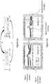
- FIG 6bAn example of the application of the digital correction according to the invention is illustrated in figure 6b .
- the figure 6bshows the interfering signal I as seen in the combined signal R2 therefore at the input of the digital correction ("Original interfering signal"), the residual interfering signal after digital correction and present in the resulting signal Ru ( "Residual interfering signal”), and the useful signal present in the resulting signal Ru ("Useful signal”).
- the left sideshows the "residual interfering signal” after a few iterations of the digital correction.
- the figure on the rightshows the “residual interfering signal” after convergence of the digital correction.
- the figure 6brepresents the application of digital correction using an iterative procedure implemented by the digital signal processing device 50. It is obvious that after convergence, the useful signal in the frequency band of the receiver is reduced compared to the starting situation and compared to that after only a few iterations. In addition, in the receiver frequency band, the level of interfering signal is reduced to the level of thermal noise present in the received signal R.
- the method 100 according to the inventionfurther comprises a digital filtering step applied before the digital correction processing 50 of the first digital reference signal Ref1n, of the digital modified reference signal Ref2n, if the latter is used, and of the digital combined signal R2n in order to select the frequency range which corresponds to the reception band of the receiver RE.
- this stepmakes it possible to limit the application of the digital correction to the reception band of the useful signal.
- the inventionalso relates to a terminal or equipment for transmitting / receiving a radio signal comprising at least one transmitting antenna connected to a transmitting equipment and a receiving antenna connected to a receiving equipment, said transmitting / reception being characterized in that it comprises the device for reducing the intensity 1 of an interfering signal.
- Another object of the inventionis a terminal or equipment for transmitting / receiving a radio signal comprising an antenna connected both to a transmitting equipment and to a receiving equipment, said equipment being characterized in that it comprises a device 1 for reducing the intensity of an interfering signal.
Landscapes
- Engineering & Computer Science (AREA)
- Computer Networks & Wireless Communication (AREA)
- Signal Processing (AREA)
- Noise Elimination (AREA)
Description
Translated fromFrenchLe domaine de l'invention concerne les systèmes traitant les interférences entre différents systèmes de communication radio co-localisés pour les réduire, voire les supprimer. A cet effet, le domaine de l'invention concerne l'élimination des interférences par application d'une correction analogique et d'une correction numérique. L'invention concerne un dispositif et un procédé pour la réduction de l'intensité d'un signal interférant présent dans un signal reçu.The field of the invention relates to systems dealing with interference between different co-located radio communication systems in order to reduce or even eliminate them. To this end, the field of the invention relates to the elimination of interference by applying an analog correction and a digital correction. The invention relates to a device and a method for reducing the intensity of an interfering signal present in a received signal.
Quand deux équipements radio sont placés à proximité ils peuvent interférer, ce qui entraîne une dégradation de la qualité des communications. Plus précisément, le signal émis par un émetteur, appelé également signal « direct » ou signal « interférant », se superpose au signal « utile » reçu par un récepteur.When two radio devices are placed nearby they can interfere, which results in a degradation of the quality of communications. More precisely, the signal emitted by a transmitter, also called “direct” signal or “interfering” signal, is superimposed on the “useful” signal received by a receiver.
A cause de la proximité entre les deux équipements le signal direct est très intense par rapport au signal utile, qui contient les informations qui doivent être reçues par le récepteur.Because of the proximity between the two devices, the direct signal is very strong compared to the useful signal, which contains the information which must be received by the receiver.
Les interférences entre les deux équipements sont dues principalement à deux effets.Interference between the two devices is mainly due to two effects.
Du fait que le signal émis par l'émetteur est très intense au niveau de l'antenne du récepteur, les amplificateurs de ce dernier peuvent être saturés. Cet effet, connu également comme désensibilisation du récepteur, peut avoir lieu même si la porteuse de l'équipement émetteur se trouve en dehors de la bande de réception de l'équipement récepteur.Because the signal from the transmitter is very strong at the receiver antenna, the receiver's amplifiers may be saturated. This effect, also known as receiver desensitization, can take place even if the carrier of the transmitting equipment is outside the reception band of the receiving equipment.
Le deuxième effet est dû au bruit large bande qui est associé au signal direct. Ce bruit large bande peut être du notamment aux non-linéarités des différents modules présents au niveau de l'émetteur. Ce bruit large bande peut recouvrir totalement ou partiellement la bande fréquentielle de réception du deuxième équipement.The second effect is due to the broadband noise that is associated with the direct signal. This broadband noise can be due in particular to the non-linearities of the different modules present at the level of the transmitter. This broadband noise can completely or partially cover the reception frequency band of the second equipment.
Les interférences sont particulièrement importantes quand la bande fréquentielle de l'émetteur est proche de la bande fréquentielle du récepteur voire quand les deux bandes fréquentielles sont coïncidentes.Interference is particularly important when the frequency band of the transmitter is close to the frequency band of the receiver or even when the two frequency bands are coincident.
Une des solutions connues de l'homme du métier pour la réduction de l'intensité du signal interférant est l'utilisation de filtres radiofréquence ou filtres RF.One of the solutions known to those skilled in the art for reducing the intensity of the interfering signal is the use of radio frequency filters or RF filters.
Néanmoins, ces solutions se révèlent peu pratiques du fait de devoir choisir des filtres RF spécifiques pour chaque bande d'émission/réception ou non applicables quand l'émission et la réception utilisent la même bande de fréquence. De plus, les filtres RF produisent des pertes d'insertion qui peuvent diminuer la puissance du signal émis lorsqu'ils sont placés en émission et la sensibilité de l'équipement récepteur lorsqu'ils sont placés en réception.However, these solutions prove impractical because of the need to choose specific RF filters for each transmit / receive band or not applicable when the transmit and receive use the same frequency band. In addition, the RF filters produce insertion losses which can reduce the power of the signal transmitted when they are placed in transmission and the sensitivity of the receiving equipment when they are placed in reception.
D'autres solutions connues de l'homme du métier concernent l'élimination physique des interférences par soustraction ou compensation du signal interférant. Ces méthodes reposent sur une soustraction analogique d'un signal référence au signal reçu afin de récupérer le signal utile uniquement.Other solutions known to those skilled in the art relate to the physical elimination of interference by subtraction or compensation of the interfering signal. These methods are based on an analog subtraction of a signal referring to the received signal in order to recover the useful signal only.
Le signal référence peut être obtenu en réalisant une copie analogique du signal émis et en modifiant son amplitude et phase à l'aide d'un circuit de traitement analogique.The reference signal can be obtained by making an analog copy of the transmitted signal and by modifying its amplitude and phase using an analog processing circuit.
Ce procédé de correction analogique est très adapté pour l'élimination des effets de désensibilisation du récepteur et permet d'éviter la saturation de l'équipement récepteur. Néanmoins ce procédé de correction analogique n'est efficace que si la copie analogique du signal émis est suffisamment bien synchronisée temporellement avec l'interférence à éliminer. De plus, les solutions connues de l'homme du métier ne permettent pas de prendre en compte les distorsions du signal référence introduites par le circuit de traitement analogique.This analog correction method is very suitable for eliminating the effects of desensitization of the receiver and makes it possible to avoid saturation of the receiving equipment. However, this analog correction method is only effective if the analog copy of the transmitted signal is sufficiently well synchronized in time with the interference to be eliminated. In addition, the solutions known to those skilled in the art do not make it possible to take into account the distortions of the reference signal introduced by the analog processing circuit.
Certains systèmes, également connus de l'homme du métier, permettent de réaliser un traitement numérique des interférences dans la bande de l'équipement récepteur. Ce traitement permet généralement de combiner les signaux en réalisant des opérations plus complexes qui ne seraient pas possibles avec des traitements analogiques. Un exemple d'un tel système est décrit dans le document
Dans ce cas le signal référence est un signal numérique prélevé au niveau de l'équipement émetteur avant sa conversion en format analogique, opération préalable à la transmission.In this case, the reference signal is a digital signal taken from the transmitting equipment before its conversion into analog format, an operation prior to transmission.
Néanmoins, le signal référence numérique étant prélevé avant la conversion en signal analogique, ces solutions sont incapables de prendre en compte les non-linéarités de la chaîne d'amplification de l'équipement émetteur. Ces non-linéarités sont au moins en partie responsables du bruit large bande observé dans le canal de réception.However, the digital reference signal being taken before conversion to analog signal, these solutions are unable to take into account the non-linearities of the amplification chain of the transmitting equipment. These non-linearities are at least partly responsible for the broadband noise observed in the reception channel.
Pour pallier ces difficultés, un premier aspect de la présente invention, qui est définie par les revendications, concerne un dispositif de traitement d'un signal reçu par un récepteur perturbé par un émetteur, lesdits émetteur et récepteur étant co-localisés, ledit dispositif étant caractérisé en ce qu'il comprend :
- un premier coupleur configuré pour prélever un premier signal référence à partir d'un signal interférant émis par l'émetteur, ledit premier signal référence étant prélevé après la chaîne d'amplification reliée à l'antenne de l'émetteur ;
- un circuit analogique de traitement du premier signal référence délivrant un signal référence modifié, ledit circuit analogique de traitement modifiant l'un au moins des paramètres parmi lesquels : l'amplitude et/ou la phase et/ou le décalage temporel du premier signal référence, le signal référence modifié étant adapté pour compenser le signal interférant émis par l'émetteur et présent dans le signal reçu par le récepteur ;
- un second coupleur configuré pour combiner le signal référence modifié avec le signal reçu par une antenne du récepteur et délivrant le signal combiné à un deuxième module de conversion analogique numérique;
- un premier module de conversion analogique numérique numérisant le premier signal référence afin de délivrer à un dispositif numérique de traitement des signaux un premier signal de référence numérique ;
- le deuxième module de conversion analogique numérisant le signal combiné afin de délivrer un signal combiné numérique au dispositif numérique de traitement des signaux, le dispositif de traitement de signaux combinant le signal combiné numérique et au moins le premier signal référence numérique afin de réduire l'intensité du signal interférant présent dans le signal combiné numérique, ledit dispositif de traitement des signaux délivrant un signal résultant numérique à un module de traitement de l'information de l'équipement récepteur.
- a first coupler configured to take a first reference signal from an interfering signal transmitted by the transmitter, said first reference signal being taken after the amplification chain connected to the antenna of the transmitter;
- an analog circuit for processing the first reference signal delivering a modified reference signal, said analog processing circuit modifying at least one of the parameters among which: the amplitude and / or the phase and / or the time offset of the first reference signal, the modified reference signal being adapted to compensate for the interfering signal transmitted by the transmitter and present in the signal received by the receiver;
- a second coupler configured to combine the modified reference signal with the signal received by an antenna of the receiver and delivering the combined signal to a second analog-to-digital conversion module;
- a first analog to digital conversion module digitizing the first reference signal in order to deliver a first digital reference signal to a digital signal processing device;
- the second analog conversion module digitizing the combined signal in order to deliver a digital combined signal to the digital signal processing device, the signal processing device combining the digital combined signal and at least the first digital reference signal in order to reduce the intensity of the interfering signal present in the digital combined signal, said signal processing device delivering a resulting digital signal to an information processing module of the receiving equipment.
On entend par émetteur radio un module d'émission de signaux radio relié à une antenne.By radio transmitter is meant a module for transmitting radio signals connected to an antenna.
On entend par récepteur radio un module de réception de signaux radio relié à une antenne.By radio receiver is meant a module for receiving radio signals connected to an antenna.
On entend par récepteur et émetteur co-localisés deux équipements placés à proximité. Quand un émetteur et un récepteur sont co-localisés le signal émis par l'émetteur interfère avec le signal utile reçu par le récepteur. Le signal reçu par le récepteur est donc une combinaison du signal interférant émis par l'émetteur et du signal utile. Par exemple un émetteur et un récepteur placés sur le toit d'un même véhicule sont co-localisés au sens de l'invention.The term “receiver and transmitter co-located” means two pieces of equipment placed nearby. When a transmitter and a receiver are co-located, the signal transmitted by the transmitter interferes with the useful signal received by the receiver. The signal received by the receiver is therefore a combination of the interfering signal transmitted by the transmitter and the useful signal. For example, a transmitter and a receiver placed on the roof of the same vehicle are co-located within the meaning of the invention.
L'émetteur et le récepteur co-localisés peuvent par exemple être placés sur deux équipements radio différents voire être placé sur un même équipement.The co-located transmitter and receiver can for example be placed on two different radio devices or even be placed on the same device.
L'émetteur et le récepteur peuvent être reliés à une même antenne.The transmitter and the receiver can be connected to the same antenna.
On entend par signal interférant le signal émis par l'antenne de l'émetteur et reçu par l'antenne du récepteur.By interfering signal is meant the signal transmitted by the antenna of the transmitter and received by the antenna of the receiver.
On entend par signal reçu par le récepteur le signal comprenant la superposition d'un signal utile et du signal interférant.The signal received by the receiver means the signal comprising the superposition of a useful signal and the interfering signal.
On entend par signal utile le signal contenant les informations destinées à l'équipement radio équipé avec le récepteur.By useful signal is meant the signal containing the information intended for the radio equipment equipped with the receiver.
On entend par circuit analogique de traitement un circuit capable de modifier la phase et/ou l'amplitude et/ou le décalage temporel du signal à son entrée. Dans la présente invention le signal en entrée du circuit analogique est une copie du signal interférant.By analog processing circuit is meant a circuit capable of modifying the phase and / or the amplitude and / or the time offset of the signal at its input. In the present invention, the signal at the input of the analog circuit is a copy of the interfering signal.
On entend par coupleur configuré pour combiner le premier signal de référence avec le signal reçu, par exemple, un circuit capable de sommer les deux signaux.The term coupler is configured to combine the first reference signal with the received signal, for example, a circuit capable of summing the two signals.
On entend par module de conversion analogique numérique un ensemble de circuits capable de numériser un signal analogique en entrée. Dans une réalisation particulière de la présente invention un tel module de conversion analogique numérique comprend au moins un convertisseur analogique numérique, au moins un filtre passe bas et au moins un mélangeur pour la décomposition en bande de base des signaux en entrée. Par exemple, un tel module de conversion analogique numérique délivre à sa sortie les deux composantes en bande de base du signal en entrée.The term “analog-to-digital conversion module” means a set of circuits capable of digitizing an analog signal at the input. In a particular embodiment of the present invention, such an analog-to-digital conversion module comprises at least one analog-to-digital converter, at least one low-pass filter and at least one mixer for the decomposition into baseband of the input signals. For example, such an analog-to-digital conversion module delivers at its output the two baseband components of the input signal.
On entend par dispositif de traitement numérique des signaux un dispositif capable de réaliser des opérations mathématiques sur des signaux numériques par exemple à l'aide d'au moins un microprocesseur. Un dispositif de traitement numérique au sens de l'invention peut être intégré dans un ordinateur ou tout autre dispositif de calcul numérique. Dans le cas de l'invention ce dispositif de traitement numérique des signaux peut par exemple minimiser l'écart entre le signal combiné numérique et le signal référence numérique afin de retrouver le signal utile.The term “digital signal processing device” is understood to mean a device capable of performing mathematical operations on digital signals, for example using at least one microprocessor. A digital processing device within the meaning of the invention can be integrated into a computer or any other digital computing device. In the case of the invention, this digital signal processing device can for example minimize the difference between the combined digital signal and the digital reference signal in order to find the useful signal.
De façon générale, le dispositif selon l'invention permet de traiter le signal reçu par le récepteur. Le signal reçu contient le signal utile, formé par les informations destinées aux utilisateurs du récepteur. En plus du signal utile, le signal reçu contient le signal interférant émis par le premier équipement radio. Il peut comprendre également du bruit.In general, the device according to the invention makes it possible to process the signal received by the receiver. The received signal contains the useful signal, formed by the information intended for the users of the receiver. In addition to the useful signal, the received signal contains the interfering signal emitted by the first radio equipment. It may also include noise.
Le dispositif selon l'invention permet d'extraire le signal utile du signal reçu, notamment en réduisant l'intensité du signal interférant dans le signal reçu par le récepteur.The device according to the invention makes it possible to extract the useful signal from the received signal, in particular by reducing the intensity of the interfering signal in the signal received by the receiver.
L'élimination du signal interférant est réalisée par le dispositif selon l'invention à l'aide d'une première correction analogique et d'une deuxième correction numérique.The interference signal is eliminated by the device according to the invention using a first analog correction and a second digital correction.
La première correction analogique est effectuée en combinant le signal référence modifié et le signal reçu. A cette fin, le circuit de traitement analogique fournit le signal référence modifié qui est par exemple une copie du signal interférant, prise en sortie de l'émetteur, modifié en amplitude de façon à ce que son amplitude soit égale à celle du signal interférant présent dans le signal reçu et déphasé de façon à ce que sa phase soit à 180° de celle du signal interférant présent dans le signal reçu. La combinaison des deux signaux est réalisée à l'aide du deuxième coupleur afin de compenser le signal interférant présent dans le signal reçu.The first analog correction is made by combining the modified reference signal and the received signal. To this end, the analog processing circuit supplies the modified reference signal which is for example a copy of the interfering signal, taken at the output of the transmitter, modified in amplitude so that its amplitude is equal to that of the interfering signal present. in the received signal and phase shifted so that its phase is 180 ° from that of the interfering signal present in the received signal. The two signals are combined using the second coupler to compensate for the interfering signal present in the received signal.
Par exemple, quand le signal référence modifié est une copie du signal interférant, prise en sortie de l'émetteur, modifié en amplitude de façon à ce que son amplitude soit égale à celle du signal interférant présent dans le signal reçu et déphasé de façon à ce que sa phase soit à 180° de celle du signal interférant présent dans le signal reçu, le deuxième coupleur effectue la somme du signal référence modifié et du signal reçu afin d'effacer le signal interférant présent dans le signal reçu. Le deuxième coupleur fournit à sa sortie le signal combiné, à savoir le signal reçu auquel le signal référence modifié a été ajouté.For example, when the modified reference signal is a copy of the interfering signal, taken at the output of the transmitter, modified in amplitude so that its amplitude is equal to that of the interfering signal present in the received signal and out of phase so as to that its phase is 180 ° from that of the interfering signal present in the received signal, the second coupler performs the sum of the modified reference signal and the received signal in order to erase the interfering signal present in the received signal. The second coupler provides at its output the combined signal, namely the received signal to which the modified reference signal has been added.
Avantageusement, la première correction analogique permet de manipuler des signaux très intenses et elle est particulièrement adaptée pour éviter le phénomène de saturation du récepteur.Advantageously, the first analog correction makes it possible to manipulate very intense signals and it is particularly suitable for avoiding the phenomenon of saturation of the receiver.
Avantageusement, le signal référence analogique, appelé premier signal référence et utilisé pour la correction analogique, est prélevé après la chaîne d'amplification de l'émetteur. Cela permet de prendre en compte toutes les distorsions analogiques introduites par les différents modules de l'émetteur et de rendre plus efficace la correction numérique.Advantageously, the analog reference signal, called the first reference signal and used for analog correction, is taken after the amplification chain of the transmitter. This makes it possible to take into account all the analog distortions introduced by the different modules of the transmitter and to make digital correction more effective.
Le dispositif selon l'invention applique aussi une correction numérique au signal reçu par le deuxième équipement à l'aide d'un signal référence numérique.The device according to the invention also applies a digital correction to the signal received by the second equipment using a digital reference signal.
La correction numérique est réalisée à l'aide du dispositif de traitement numérique des signaux. Le dispositif de traitement numérique des signaux combine le signal combiné numérique et au moins un signal référence numérique.Digital correction is carried out using the digital signal processing device. The digital signal processing device combines the digital combined signal and at least one digital reference signal.
Avantageusement, la correction numérique permet d'effectuer des opérations mathématiques complexes en combinant au moins deux signaux numériques.Advantageously, digital correction makes it possible to perform complex mathematical operations by combining at least two digital signals.
Avantageusement, la correction numérique permet d'éliminer le signal interférant résiduel après la correction analogique.Advantageously, the digital correction makes it possible to eliminate the residual interfering signal after the analog correction.
Avantageusement, la correction numérique permet d'éliminer les interférences dues au bruit large bande du signal interférant dans la bande fréquentielle du récepteur dans le cas où les fréquences émission et réception sont différentes.Advantageously, the digital correction makes it possible to eliminate the interference due to broadband noise from the signal interfering in the frequency band of the receiver in the case where the transmit and receive frequencies are different.
Avantageusement, le signal référence numérique est obtenu par numérisation du premier signal référence qui est prélevé en sortie de l'émetteur et notamment après la chaîne d'amplification de l'émetteur. Cela permet de prendre en compte l'ensemble de toutes les distorsions analogiques introduites par les différents modules de l'émetteur.Advantageously, the digital reference signal is obtained by digitizing the first reference signal which is taken at the output of the transmitter and in particular after the amplification chain of the transmitter. This makes it possible to take into account all of the analog distortions introduced by the different modules of the transmitter.
A titre d'exemple, la correction numérique peut être appliquée en minimisant par procédure itérative la différence entre le signal combiné numérique - c'est-à-dire le signal reçu auquel la première correction analogique a été appliquée et qui a été numérisé - et le signal référence numérique multiplié par un paramètre d'ajustement. Cette procédure permet d'extraire le signal utile et de le transmettre à un module de traitement de l'information du récepteur.For example, the digital correction can be applied by minimizing by iterative procedure the difference between the combined digital signal - that is to say the received signal to which the first analog correction has been applied and which has been digitized - and the digital reference signal multiplied by an adjustment parameter. This procedure extracts the useful signal and transmits it to an information processing module of the receiver.
Selon un mode de réalisation, deux signaux de référence sont utilisés, le premier signal référence numérisé et le signal référence modifié numérisé. Le signal référence modifié numérisé est obtenu en numérisant le signal référence modifié prélevé en sortie du circuit de traitement analogique.According to one embodiment, two reference signals are used, the first digitized reference signal and the digitized modified reference signal. The digitized modified reference signal is obtained by digitizing the modified reference signal taken from the output of the analog processing circuit.
Avantageusement, le signal référence modifié numérisé permet de prendre en compte, lors de l'élimination numérique des interférences, les éventuelles distorsions introduites par le circuit de traitement analogique du premier signal référence.Advantageously, the digitized modified reference signal makes it possible to take into account, during the digital elimination of the interference, any distortions introduced by the analog processing circuit of the first reference signal.
Le dispositif de réduction de l'intensité d'un signal interférant selon l'invention peut également présenter une ou plusieurs des caractéristiques ci-dessous, considérées individuellement ou selon toutes les combinaisons techniquement possibles :
- il comprend un troisième module de conversion analogique numérique numérisant le signal référence modifié afin de délivrer au dispositif numérique de traitement des signaux un signal référence modifié numérique, ledit signal référence modifié étant prélevé après le circuit de traitement analogique, le dispositif de traitement de signaux combinant le signal combiné numérique et deux signaux référence numériques, le premier signal référence numérique et le signal référence modifié numérique afin de réduire l'intensité du signal interférant présent dans le signal combiné numérique, ledit dispositif de traitement des signaux délivrant un signal résultant numérique à un module de traitement de l'information de l'équipement récepteur ;
- le récepteur est un récepteur de type bande étroite dont la largeur de bande est inférieure à 10MHz ;
- au moins un module de conversion analogique numérique comprend au moins un des éléments suivants : un oscillateur local, un mélangeur pour la décomposition du signal en entrée en bande de base, un filtre passe bas pour éliminer la fréquence image, un convertisseur analogique numérique pour fournir la version numérique des composantes en bande de base du signal en entrée ;
- le circuit de traitement analogique comprend au moins un déphaseur variable et un gain variable pour la génération du signal référence modifié;
- le circuit de traitement analogique comprend en outre un circuit à retard fixe et/ou un circuit à retard paramétrable pour la génération du signal référence modifié.
- le dispositif numérique de traitement des signaux comprend au moins un processeur ou d'autres moyens de calcul.
- it includes a third analog-to-digital conversion module digitizing the modified reference signal in order to deliver a digital modified reference signal to the digital signal processing device, said modified reference signal being taken after the analog processing circuit, the signal processing device combining the digital combined signal and two digital reference signals, the first digital reference signal and the digital modified reference signal in order to reduce the intensity of the interfering signal present in the digital combined signal, said signal processing device delivering a resulting digital signal to a receiver information processing module;
- the receiver is a narrow band type receiver whose bandwidth is less than 10 MHz;
- at least one analog-to-digital conversion module comprises at least one of the following elements: a local oscillator, a mixer for the decomposition of the input signal into baseband, a low pass filter to eliminate the image frequency, an analog to digital converter to provide the digital version of the baseband components of the input signal;
- the analog processing circuit comprises at least one variable phase shifter and a variable gain for generating the modified reference signal;
- the analog processing circuit further comprises a fixed delay circuit and / or a configurable delay circuit for generating the modified reference signal.
- the digital signal processing device comprises at least one processor or other calculation means.
Un autre objet de la présente invention concerne un procédé de mise en œuvre du dispositif de réduction de l'intensité d'un signal interférant, ledit procédé comportant les étapes suivantes :
- prélèvement d'un premier signal référence à partir du signal interférant émis par l'émetteur ;
- modification des propriétés du premier signal référence à l'aide d'un circuit analogique pour obtenir un signal référence modifié, ledit signal référence modifié étant adapté pour compenser le signal interférant émis par l'émetteur et présent dans le signal reçu par le récepteur ;
- combinaison du signal référence modifié et du signal reçu par le récepteur pour obtenir le signal combiné;
- conversion analogique numérique du signal combiné pour obtenir le signal combiné numérique ;
- conversion analogique numérique du premier signal référence pour obtenir un premier signal référence numérique, ledit premier signal référence étant prélevé après la chaîne d'amplification reliée à l'antenne de l'émetteur ;
- combinaison à l'aide du dispositif de traitement des signaux du signal combiné numérique et d'au moins le premier signal référence numérique afin d'éliminer le signal interférant présent dans le signal combiné numérique ;
- envoi du signal résultant numérique à un module de traitement de l'information de l'équipement récepteur.
- sampling a first reference signal from the interfering signal emitted by the transmitter;
- modification of the properties of the first reference signal using an analog circuit to obtain a modified reference signal, said modified reference signal being adapted to compensate for the interfering signal transmitted by the transmitter and present in the signal received by the receiver;
- combining the modified reference signal and the signal received by the receiver to obtain the combined signal;
- analog to digital conversion of the combined signal to obtain the combined digital signal;
- analog-to-digital conversion of the first reference signal to obtain a first digital reference signal, said first reference signal being taken after the amplification chain connected to the antenna of the transmitter;
- combination using the digital combined signal signal processing device and at least the first digital reference signal in order to eliminate the interfering signal present in the digital combined signal;
- sending of the resulting digital signal to an information processing module of the receiving equipment.
Le procédé de mise en œuvre du dispositif de réduction de l'intensité d'un signal interférant selon l'invention peut également présenter une ou plusieurs des caractéristiques ci-dessous, considérées individuellement ou selon toutes les combinaisons techniquement possibles :
- Il comprend une étape de conversion analogique numérique du signal référence modifié pour obtenir un signal référence modifié numérique, ledit signal référence modifié étant prélevé après le circuit de traitement analogique, la combinaison numérique à l'aide du dispositif de traitement des signaux du signal combiné numérique, du premier signal référence numérique et du signal référence modifié étant réalisée afin d'éliminer le signal interférant présent dans le signal combiné numérique .
- l'étape de combinaison à l'aide du dispositif de traitement des signaux du signal combiné numérique et du premier signal référence numérique afin d'éliminer le signal interférant présent dans le signal combiné numérique comprend la minimisation itérative de l'écart entre le signal combiné numérique et le premier signal référence numérique afin d'envoyer le signal résultant numérique à un module de traitement de l'information de l'équipement récepteur, l'écart à minimiser étant de la formeR2n -
Ref1 n T.a , chacun des termes du vecteurRef1n représentant le premier signal référence numérique avec un décalage temporel numérique donné, les termes du vecteura ayant le rôle de paramètres d'ajustement; - l'étape de combinaison du signal combiné numérique et du signal référence numérique à l'aide du dispositif de traitement des signaux afin d'éliminer le signal interférant présent dans le signal combiné numérique comprend la minimisation itérative de l'écart entre le signal combiné numérique et le signal référence numérique afin d'envoyer le signal résultant numérique à un module de traitement de l'information (60) de l'équipement récepteur (RE), l'écart à minimiser étant de la forme : espérance mathématique de (∥R2n-
Ref1 n T.a ∥2), le vecteura représentant les paramètres d'ajustement, chacun des termes du vecteurRef1n représentant le premier signal référence numérique avec un décalage temporel numérique donné ; - l'étape de combinaison à l'aide du dispositif de traitement des signaux du signal combiné numérique du premier signal référence numérique et du signal référence modifié numérique afin d'éliminer le signal interférant présent dans le signal combiné numérique comprend la minimisation itérative de l'écart entre le signal somme numérique, le premier signal référence numérique et le signal référence modifié numérique afin d'envoyer le signal résultant numérique à un module de traitement de l'information du récepteur, l'écart à minimiser étant de la formeR2n" =R2n -
Ref1 n T.a1 -Ref2 n T.a2 ., chacun des termes du vecteurRef1n représentant le premier signal référence numérique avec un décalage temporel numérique donné, les termes du vecteura1 ayant le rôle de paramètres d'ajustement, chacun des termes du vecteurRef2n représentant le signal référence modifié numérique avec un décalage temporel numérique donné, les termes du vecteura2 ayant le rôle de paramètres d'ajustement ; - l'étape de combinaison du signal combiné numérique et des signaux référence numériques à l'aide du dispositif de traitement des signaux afin d'éliminer le signal interférant présent dans le signal combiné numérique comprend la minimisation itérative de l'écart entre le signal combiné numérique et les signaux référence numériques afin d'envoyer le signal résultant numérique à un module de traitement de l'information (60) de l'équipement récepteur (RE), l'écart à minimiser étant de la forme : espérance mathématique de ( ∥R2n -
Ref1 n T.a1 -Ref2 n T.a2 ∥2), le vecteura1 représentant les paramètres d'ajustement pour le premier signal référence numérique, chacun des termes du vecteurRef1n représentant le premier signal référence numérique avec un décalage temporel numérique donné ; le vecteura2 représentant les paramètres d'ajustement pour le signal référence modifié, chacun des termes du vecteurRef2n représente le signal référence modifié numérique avec un décalage temporel numérique donné; - la minimisation itérative de l'écart entre le signal combiné numérique et au moins un signal référence numériqueest réalisée à l'aide d'un algorithme de type gradient stochastique ;
- les étapes de conversion analogique numérique fournissent une représentation numérique des signaux en bande de base ;
- il comprend une étape de filtrage numérique, appliquée avant le dispositif de traitement numérique des signaux, du premier signal référence numérique, du signal référence modifié numérique et du signal combiné numérique afin de sélectionner la gamme fréquentielle qui correspond à la bande de réception du récepteur.
- It comprises a step of analog-digital conversion of the modified reference signal to obtain a digital modified reference signal, said modified reference signal being taken after the analog processing circuit, the digital combination using the signal processing device of the digital combined signal , the first digital reference signal and the modified reference signal being produced in order to eliminate the interfering signal present in the digital combined signal.
- the step of combining using the signal processing device of the digital combined signal and the first digital reference signal in order to eliminate the interfering signal present in the digital combined signal comprises iterative minimization of the difference between the combined signal digital and the first digital reference signal in order to send the resulting digital signal to an information processing module of the receiving equipment, the difference to be minimized being of the formR 2n -
Ref 1not T.at , each of the terms of the vectorRef 1n representing the first digital reference signal with a given digital time offset, the terms of the vectorat having the role of adjustment parameters; - the step of combining the digital combined signal and the digital reference signal using the signal processing device in order to eliminate the interfering signal present in the digital combined signal comprises iterative minimization of the difference between the digital combined signal and the digital reference signal in order to send the resulting digital signal to an information processing module (60) of the receiving equipment (RE), the difference to be minimized being of the form: mathematical expectation of (∥R 2n-
Ref 1not T.at ∥2 ), the vectorat representing the adjustment parameters, each of the terms of the vectorRef 1n representing the first digital reference signal with a given digital time offset; - the step of combining, using the signal processing device of the digital combined signal of the first digital reference signal and the modified digital reference signal in order to eliminate the interfering signal present in the digital combined signal, comprises iterative minimization of the difference between the digital sum signal, the first digital reference signal and the modified digital reference signal in order to send the resulting digital signal to a data processing module of the receiver, the difference to be minimized being of the formR 2n " =R 2n -
Ref 1not T.at 1 -Ref 2 not T.a 2 ., each of the terms of the vectorRef 1n representing the first digital reference signal with a given digital time offset, the terms of the vectorat1 having the role of adjustment parameters, each of the terms of the vectorRef 2n representing the digital modified reference signal with a given digital time offset, the terms of the vectora2 having the role of adjustment parameters; - the step of combining the digital combined signal and the digital reference signals using the signal processing device in order to eliminate the interfering signal present in the digital combined signal comprises iterative minimization of the difference between the digital combined signal and the digital reference signals in order to send the resulting digital signal to an information processing module (60) of the receiving equipment (RE), the difference to be minimized being of the form: mathematical expectation of (∥R 2n -
Ref 1not T.at1 -Ref 2 not T.a2 ∥2 ), the vectorat1 representing the adjustment parameters for the first digital reference signal, each of the terms of the vectorRef 1n representing the first digital reference signal with a given digital time offset; the vectora2 representing the adjustment parameters for the modified reference signal, each of the terms of the vectorRef 2n represents the digital modified reference signal with a given digital time offset; - iterative minimization of the difference between the combined digital signal and at least one digital reference signal is carried out using a stochastic gradient type algorithm;
- the analog to digital conversion steps provide a digital representation of the baseband signals;
- it includes a digital filtering step, applied before the digital signal processing device, of the first digital reference signal, of the modified digital reference signal and of the digital combined signal in order to select the frequency range which corresponds to the reception band of the receiver.
Un autre aspect de l'invention concerne un système d'émission/réception d'un signal radio comprenant au moins une antenne d'émission reliée à un équipement émetteur et une antenne de réception reliée à un équipement récepteur, ledit équipement d'émission/réception étant caractérisé en ce qu'il comprend le dispositif de réduction de l'intensité d'un signal interférant dans un signal reçu.Another aspect of the invention relates to a system for transmitting / receiving a radio signal comprising at least one transmitting antenna connected to a transmitting equipment and a receiving antenna connected to a receiving equipment, said transmitting / reception being characterized in that it comprises the device for reducing the intensity of an interfering signal in a received signal.
Un autre aspect de l'invention porte sur un équipement d'émission/réception d'un signal radio comprenant une antenne reliée à la fois à un équipement émetteur et à un équipement récepteur, ledit équipement étant caractérisé en ce qu'il comprend un dispositif de réduction de l'intensité d'un signal interférant.Another aspect of the invention relates to equipment for transmitting / receiving a radio signal comprising an antenna connected to both a transmitting equipment and a receiving equipment, said equipment being characterized in that it comprises a device reduction of the intensity of an interfering signal.
D'autres caractéristiques et avantages de l'invention ressortiront clairement de la description qui en est donnée ci-dessous, à titre indicatif et nullement limitatif, en référence aux figures annexées, parmi lesquelles :
- la
figure 1 illustre le dispositif de réduction de l'intensité d'un signal interférant selon l'invention ; - la
figure 2 illustre une façon d'implémenter la procédure de réduction analogique de l'intensité d'un signal interférant selon l'invention ; - la
figure 3 illustre un exemple de module de conversion analogique numérique ; - la
figure 4 illustre un mode de réalisation du dispositif selon l'invention ; - la
figure 5 illustre un procédé de mise en œuvre du dispositif de réduction de l'intensité d'un signal interférant ; - la
figure 6a illustre un exemple des possibles interférences entre deux équipement d'émission/transmission utilisant deux systèmes de communication radio différents ; - la
figure 6b illustre un exemple d'application de la correction numérique selon l'invention.
- the
figure 1 illustrates the device for reducing the intensity of an interfering signal according to the invention; - the
figure 2 illustrates a way of implementing the analog reduction procedure of the intensity of an interfering signal according to the invention; - the
figure 3 illustrates an example of an analog-to-digital conversion module; - the
figure 4 illustrates an embodiment of the device according to the invention; - the
figure 5 illustrates a method of implementing the device for reducing the intensity of an interfering signal; - the
figure 6a illustrates an example of possible interference between two transmission / transmission equipment using two different radio communication systems; - the
figure 6b illustrates an example of application of the digital correction according to the invention.
La
Le dispositif selon l'invention trouve application quand un émetteur EM et un récepteur RE sont co-localisés.The device according to the invention finds application when an emitter EM and a receiver RE are co-located.
Dans une telle configuration, le signal reçu R est un signal qui comprend la combinaison du signal utile et du signal émis par l'émetteur. Le signal émis par l'émetteur est considéré comme un signal interférant I.In such a configuration, the received signal R is a signal which comprises the combination of the useful signal and the signal transmitted by the transmitter. The signal emitted by the transmitter is considered to be an interfering signal I.
Le signal utile contient les informations destinées aux utilisateurs de l'équipement récepteur.The useful signal contains information intended for users of the receiving equipment.
Le dispositif selon l'invention s'avère particulièrement utile dans les situations suivantes. Dans une première situation deux terminaux ou équipements radio sont placés à proximité. Dans ce cas le premier équipement comprend un émetteur EM relié à une antenne et le deuxième équipement comprend un récepteur RE relié à une antenne.The device according to the invention proves to be particularly useful in the following situations. In a first situation two terminals or radio equipment are placed nearby. In this case, the first device comprises an EM transmitter connected to an antenna and the second device comprises a RE receiver connected to an antenna.
Grâce à la proximité de l'émetteur et du récepteur, il est possible de prélever directement une partie du signal émis. Le signal émis est utilisé comme signal référence par le dispositif 1 selon l'invention.Thanks to the proximity of the transmitter and the receiver, it is possible to directly take part of the transmitted signal. The transmitted signal is used as a reference signal by the
Le dispositif 1 selon l'invention utilise le signal référence pour appliquer une correction analogique et une correction numérique au signal reçu, afin d'en extraire le signal utile.The
Selon un autre mode de réalisation, l'émetteur EM et le récepteur RE font partie du même équipement utilisateur.According to another embodiment, the emitter EM and the receiver RE are part of the same user equipment.
L'émetteur EM et le récepteur RE peuvent soit utiliser le même système de communication radio soit utiliser deux systèmes différents.The EM transmitter and the RE receiver can either use the same radio communication system or use two different systems.
La
De façon connue de l'homme du métier, même si les gammes fréquentielles d'émission/réception ne se recouvrent pas, des effets d'interférences peuvent avoir lieu. Il s'agit notamment des effets de désensibilisation du récepteur et des interférences dues au bruit large bande généré par l'émetteur.In a manner known to those skilled in the art, even if the frequency ranges of transmission / reception do not overlap, interference effects can take place. These include the effects of receiver desensitization and interference from broadband noise generated by the transmitter.
La flèche A de
Le dispositif selon l'invention applique une double correction analogique et numérique au signal reçu par le récepteur RE, le but de la correction étant celui de réduire l'intensité du signal interférant dans le signal reçu.The device according to the invention applies a double analog and digital correction to the signal received by the receiver RE, the aim of the correction being that of reducing the intensity of the interfering signal in the received signal.
La première correction appliquée par le dispositif 1 selon l'invention est une correction analogique.The first correction applied by the
Le coupleur 10 prélève une partie du signal émis par l'émetteur EM ou signal interférant I.The
Selon un mode de réalisation, le coupleur 10 est un coupleur radiofréquence ou un diviseur de puissance asymétrique. Tout autre type de coupleur connu de l'homme du métier peut également être utilisé.According to one embodiment, the
Le signal prélevé par le coupleur 10 est dit premier signal référence Ref1. Le premier signal référence Ref1 est envoyé à un circuit de traitement analogique 20. Il est également envoyé à un premier module de conversion analogique numérique 401.The signal taken by the
Selon un mode de réalisation, le coupleur 10 est placé après la chaîne d'amplification de l'émetteur EM.According to one embodiment, the
Selon un autre mode de réalisation, le coupleur est placé avant l'antenne d'émission reliée à l'émetteur.According to another embodiment, the coupler is placed before the transmitting antenna connected to the transmitter.
Avantageusement, le coupleur 10 prélève le premier signal référence Ref1 après la chaîne d'amplification de l'émetteur ce qui permet de prendre en compte le bruit large bande introduit par les modules de sortie de l'émetteur.Advantageously, the
Le circuit de traitement analogique 20 délivre en sortie un signal référence modifié Ref2.The
Selon un mode de réalisation le signal référence modifié Ref2 est une copie du signal interférant dont l'amplitude et la phase sont opportunément modifiées.According to one embodiment, the modified reference signal Ref2 is a copy of the interfering signal whose amplitude and phase are suitably modified.
L'amplitude du signal référence modifié Ref2 est modifiée par le circuit gain variable de
La phase du signal référence modifié Ref2 est modifiée par le circuit déphaseur variable de
Selon un mode de réalisation le circuit de traitement analogique 20 modifie l'amplitude du premier signal référence et le déphase de façon à être à 180 ° par rapport au signal interférant I tel qu'il est vu dans le signal reçu R.According to one embodiment, the
Selon un mode de réalisation préféré de l'invention, le circuit de traitement analogique 20 comprend un circuit à retard amélioré selon la demande « Circuit à retard temporel d'un signal radiofréquence et dispositif d'e réduction d'interférences utilisant ledit circuit » déposée au nom d'Airbus DS SAS le 06/06/2016.According to a preferred embodiment of the invention, the
Par exemple, le circuit à retard amélioré est un circuit à retard pour le décalage temporel d'un signal radiofréquence d'entrée, ledit circuit à retard comprenant un filtre passe tout ayant une fréquence centrale donnée configuré pour linéariser le déphasage du signal de sortie par rapport au signal d'entrée en fonction de la fréquence sur une première gamme fréquentielle et caractérisé en ce qu'il comprend un premier circuit anti-résonant ayant une première fréquence centrale et un deuxième circuit anti-résonant ayant une deuxième fréquence centrale, le filtre passe tout et les deux circuits anti-résonants étant configurés et agencés pour linéariser le déphasage du signal en sortie par rapport au signal d'entrée en fonction de la fréquence sur une seconde gamme fréquentielle incluant la première gamme.For example, the improved delay circuit is a delay circuit for the time offset of an input radio frequency signal, said delay circuit comprising an all-pass filter having a given center frequency configured to linearize the phase shift of the output signal by ratio to the input signal as a function of frequency over a first frequency range and characterized in that it comprises a first anti-resonant circuit having a first central frequency and a second anti-resonant circuit having a second central frequency, the filter pass everything and them two anti-resonant circuits being configured and arranged to linearize the phase shift of the output signal with respect to the input signal as a function of frequency on a second frequency range including the first range.
Avantageusement, le circuit de traitement analogique 20 permet de régler indépendamment l'amplitude, la phase et le décalage temporel du signal référence modifié Ref2.Advantageously, the
Avantageusement, le circuit de traitement analogique 20 selon l'invention permet grâce au circuit à retard amélioré d'introduire un retard temporel constant ou quasi-constant sur la bande de réception du récepteur, ce qui est particulièrement adapté quand le récepteur est de type large bande.Advantageously, the
Le deuxième coupleur 40 combine le signal référence modifié Ref2 avec le signal reçu R et délivre en sortie le signal combiné R2 afin de compenser le signal interférant I tel qu'il est vu dans le signal reçu R.The
Grâce aux modifications d'intensité et phase introduites par le circuit de traitement 20, le signal référence modifié Ref2 efface au moins partiellement le signal interférant I tel qu'il est vu dans le signal reçu R. Autrement dit, le dispositif 1 selon l'invention réduit l'intensité du signal interférant I dans le signal reçu R.Thanks to the intensity and phase modifications introduced by the
Selon un mode de réalisation particulier le deuxième coupleur 40 effectue la somme du signal référence modifié Ref2 et du signal reçu R.According to a particular embodiment, the
Avantageusement, quand le circuit de traitement analogique 20 modifie l'amplitude du premier signal référence de façon à ce que l'amplitude du signal référence modifié soit égale à l'amplitude du signal interférant I tel que vu dans le signal reçu R et le déphase de façon à être à 180° du signal I tel que vu dans le signal reçu R, le signal référence modifié ainsi obtenu peut être simplement sommé au signal reçu R afin d'effacer le signal interférant I.Advantageously, when the
Le signal combiné R2 délivré par le deuxième coupleur 20 est donc le signal reçu auquel une première correction analogique a été appliquée.The combined signal R2 delivered by the
Selon un mode de réalisation, les paramètres du circuit de traitement analogique 20 sont réglés à l'aide d'une boucle de contrôle 25. La boucle de contrôle 25 est également une boucle de caractérisation du signal combiné R2.According to one embodiment, the parameters of the
La boucle de contrôle 25 reçoit en entrée une partie du signal combiné R2, prélevée par un coupleur 45 en sortie du deuxième coupleur 40.The
La boucle de contrôle 25 comprend au moins un amplificateur radiofréquence, un détecteur de puissance radiofréquence et une unité de contrôle Log.The
L'unité de contrôle Log modifie les paramètres du circuit de traitement analogique 20 pour minimiser l'intensité du signal interférant dans le signal combiné R2.The Log control unit modifies the parameters of the
Avantageusement, la boucle de contrôle 25 permet d'optimiser les paramètres du circuit de traitement 20 pour minimiser le niveau du signal interférant dans le signal combiné R2.Advantageously, the
Avantageusement, la correction analogique à l'aide du signal référence modifié Ref2 permet de traiter des signaux très intenses, ce qui est adapté pour prévenir les effets de saturation et désensibilisation dus au signal interférant.Advantageously, the analog correction using the modified reference signal Ref2 makes it possible to process very intense signals, which is suitable for preventing the effects of saturation and desensitization due to the interfering signal.
Selon un mode de réalisation, le circuit à retard variable de
Selon un mode de réalisation, le circuit à retard variable de
Avantageusement, le placement du circuit à retard variable entre un équipement et l'antenne auquel il est relié permet d'introduire un retard sur le chemin antenne. Cela s'avère particulièrement utile quand le chemin antenne est parcouru plus rapidement que le circuit de traitement analogique 20 ou circuit de compensation. Par exemple, ce placement du circuit à retard est particulièrement avantageux quand les deux équipements EM et RE utilisent la même antenne.Advantageously, the placement of the variable delay circuit between an item of equipment and the antenna to which it is connected makes it possible to introduce a delay on the antenna path. This is particularly useful when the antenna path is traversed faster than the
Une partie du signal interférant peut encore être présente dans le signal combiné R2. Cela vient par exemple du bruit large bande introduit par les étapes d'amplifications de l'émetteur, qui peuvent avoir des comportements non-linéaires.Part of the interfering signal may still be present in the combined signal R2. This comes, for example, from the broadband noise introduced by the amplifier amplification steps, which can have non-linear behaviors.
L'élimination de ce bruit large bande et / ou des multi trajets RF demande des opérations mathématiques plus complexes, pour lesquelles les traitements analogiques ne sont pas adaptés.The elimination of this broadband noise and / or of the RF multiple paths requires more complex mathematical operations, for which the analog processing is not suitable.
Pour en tenir compte le dispositif 1 selon l'invention applique une deuxième correction au signal reçu R, cette correction est numérique et est appliquée au signal combiné R2.To take account of this, the
Le premier module de conversion analogique numérique 401 délivre à sa sortie le premier signal référence numérisé Ref1n.The first analog to
Le deuxième module de conversion analogique numérique 402 délivre à sa sortie le signal combiné numérique R2n.The second analog-to-
Un module de conversion analogique numérique selon un mode de réalisation de l'invention est illustré à la
Selon un mode de réalisation les modules de conversion analogique numérique comprennent au moins un oscillateur local LO et un mélangeur IQM.According to one embodiment, the analog-to-digital conversion modules comprise at least one local oscillator LO and an IQM mixer.
Avantageusement, l'oscillateur local LO et le mélangeur IQM permettent d'obtenir une représentation du signal en bande de base.Advantageously, the local oscillator LO and the mixer IQM make it possible to obtain a representation of the signal in baseband.
Selon un mode de réalisation les modules de conversion 401,402 comprennent en outre au moins un filtre passe bas LPF.According to one embodiment, the
Avantageusement, les filtres passe bas LPF permettent de filtrer la fréquence image.Advantageously, the low pass filters LPF make it possible to filter the image frequency.
Les modules de conversion analogique numérique 401, 402 comprennent également au moins un convertisseur analogique numérique CAN afin de délivrer en sortie la version numérique du signal en entrée.The analog to
Selon un mode de réalisation les convertisseurs analogique numérique délivrent les composantes en bande de base numérisées du signal en entrée.According to one embodiment, the analog-to-digital converters deliver the digitized baseband components of the input signal.
Le dispositif numérique de traitement des signaux 50 reçoit en entrée un ou plusieurs signaux référence numériques et le signal combiné numérique R2n.The digital
Selon un mode de réalisation, illustré à la
Avantageusement, ce mode de réalisation permet de prendre en compte dans le signal numérisé Ref1n le bruit large bande introduit par les non-linéarités de la chaîne d'amplification de l'émetteur.Advantageously, this embodiment makes it possible to take into account in the digital signal Ref1n the broadband noise introduced by the non-linearities of the amplification chain of the transmitter.
Selon un mode de réalisation, illustré à la
Un avantage de ce mode de réalisation est de prendre en compte dans le signal référence modifié numérique les distorsions introduites par le circuit de traitement analogique 20 et qui peuvent empêcher une correction complète du bruit large bande présent dans le signal reçu et qui peut masquer ou gêner le signal utileAn advantage of this embodiment is to take into account in the digital modified reference signal the distortions introduced by the
Selon un mode de réalisation, illustré à la
Selon un mode de réalisation, le dispositif numérique de traitement des signaux 50 minimise la différenceR2n' =R2n -
Les termes du vecteur
Une fois la procédure itérative complétée, R2n' représente le signal résultant numérique Run, qui est une approximation du signal utile numérisé, obtenu par le dispositif 1 en réduisant l'intensité du signal interférant I dans le signal reçu R avec une double correction analogique et numérique.Once the iterative procedure has been completed, R2n ′ represents the resulting digital signal Run, which is an approximation of the useful digital signal obtained by the
Selon ce mode de réalisation le dispositif de traitement numérique des signaux minimise la quantitéR2n' =R2n -
Par exemple, la quantité à minimiser peut être l'espérance mathématique de ∥R2n -
Les termes du vecteur
Selon un mode particulier de réalisation, R2n' peut être minimisé en utilisant un algorithme de type gradient stochastique.According to a particular embodiment, R2n ′ can be minimized by using a stochastic gradient type algorithm.
Avantageusement, ce mode de réalisation permet d'appliquer une correction numérique au signal combiné R2 auquel une première correction analogique avait été appliquée.Advantageously, this embodiment makes it possible to apply a digital correction to the combined signal R2 to which a first analog correction had been applied.
Avantageusement, la deuxième correction qui est une correction numérique permet d'éliminer, dans la bande du signal utile, le bruit large bande associé au signal interférant.Advantageously, the second correction which is a digital correction makes it possible to eliminate, in the band of the useful signal, the broadband noise associated with the interfering signal.
Avantageusement, la correction numérique permet d'extraire le signal utile présent dans le signal reçu afin de l'envoyer à un module de traitement de l'information 60 du récepteur.Advantageously, digital correction makes it possible to extract the useful signal present in the received signal in order to send it to an
Selon un mode de réalisation, le dispositif numérique de traitement de signaux 50 contient au moins un micro-processeur.According to one embodiment, the digital
Selon un mode de réalisation le dispositif numérique de traitement de signaux 50 peut être inséré dans un ordinateur ou tout autre dispositif de calcul.According to one embodiment, the digital
Selon un mode particulier de réalisation deux signaux de référence sont utilisés, le premier signal référence numérique Ref1n et le signal référence modifié numérique Ref2n.According to a particular embodiment, two reference signals are used, the first digital reference signal Ref1n and the digital modified reference signal Ref2n.
Selon ce mode de réalisation un troisième module de conversion analogique numérique 403 fournit le signal modifié numérique Ref2n.According to this embodiment, a third analog-to-
Selon ce mode de réalisation le dispositif de traitement numérique des signaux minimise la quantitéR2n" =R2n -
Par exemple la quantité à minimiser peut être l'espérance mathématique de ∥R2n -
Selon un mode de réalisation particulier les valeurs des paramètres
Il est aussi possible de concaténer les vecteurs
Le signal R2n" représente le signal résultant numérique Run qui est une approximation du signal utile numérisé. Le signal résultant numérique Run est le signal envoyé à un équipement de traitement des informations 60 du récepteur RE.The signal R2n ″ represents the resulting digital signal Run which is an approximation of the useful digital signal. The resulting digital signal Run is the signal sent to an
Un autre objet de la présente invention est un procédé 100 de mise en œuvre du dispositif 1 pour la réduction de l'intensité d'un signal interférant dans un signal reçu. Le procédé 100 est illustré à la
La première étape du procédé 100 est le prélèvement PRE-Ref1 d'un signal référence Ref1 à partir du signal interférant I émis par l'émetteur EM.The first step of
Cette étape est réalisée à l'aide par exemple du coupleur 10 placé après la chaîne d'amplification de l'émetteur EM.This step is carried out using for example the
Avantageusement, cette étape permet d'inclure dans le signal Ref1 le bruit large bande généré par l'émetteur EM.Advantageously, this step makes it possible to include in the signal Ref1 the broadband noise generated by the emitter EM.
La deuxième étape du procédé 100 est la modification MOD-Ref1 des propriétés du premier signal référence Ref1 à l'aide d'un circuit analogique 20 pour obtenir un signal référence modifié Ref2, ledit signal référence modifié Ref2 étant adapté pour compenser le signal interférant I émis par l'émetteur et présent dans le signal reçu R par le récepteur RE.The second step of the
Cette étape permet de préparer le signal référence modifié Ref2, utilisé pour compenser le signal interférant présent dans le signal reçu.This step prepares the modified reference signal Ref2, used to compensate for the interfering signal present in the received signal.
Selon un mode de réalisation particulier de l'étape MOD-Ref1, les propriétés du signal référence modifié Ref2 sont déterminées par la boucle de contrôle 25 de la
Avantageusement la boucle de contrôle 25 mesure le niveau du signal interférant dans le signal reçu.Advantageously, the
Toujours dans la
L'étape CORR1 du procédé 100 selon l'invention comprend la combinaison analogique du signal référence modifié Ref2 et du signal reçu R par le récepteur pour obtenir le signal combiné R2.Step CORR1 of the
Avantageusement, cette étape constitue la correction analogique appliquée au signal reçu R et délivre le signal combiné R2.Advantageously, this step constitutes the analog correction applied to the received signal R and delivers the combined signal R2.
Par exemple si le signal référence modifié est la copie du signal interférant I, avec une amplitude proche de celle de l'interférence telle que vue dans le signal reçu R et avec un déphasage proche de 180° par rapport à l'interférence telle que vue dans le signal reçu R, en sommant le signal reçu R et le signal référence modifié Ref2 l'intensité du signal interférant I présent dans R est sensiblement réduite dans le signal combiné R2.For example if the modified reference signal is a copy of the interfering signal I, with an amplitude close to that of the interference as seen in the received signal R and with a phase shift close to 180 ° relative to the interference as seen in the received signal R, by summing the received signal R and the modified reference signal Ref2 the intensity of the interfering signal I present in R is significantly reduced in the combined signal R2.
Les étapes NUM-R2 et CORR2 permettent d'appliquer une deuxième correction numérique au signal combiné R2.The steps NUM-R2 and CORR2 make it possible to apply a second digital correction to the combined signal R2.
L'étape NUM-R2 comprend la conversion analogique numérique du signal combiné R2 pour obtenir le signal combiné numérique R2n. La conversion numérique est effectuée à l'aide du module de conversion analogique numérique 402.The NUM-R2 step includes analog-to-digital conversion of the combined signal R2 to obtain the digital combined signal R2n. The digital conversion is carried out using the analog to
L'étape CORR2 est réalisée à l'aide d'un dispositif numérique de traitement des signaux et comprend la combinaison numérique d'un signal référence numérique, comprenant au moins le premier signal référence numérique Ref1n, et du signal combiné numérique R2n, afin de minimiser l'intensité du signal interférant I dans le signal combiné numérique R2n.The step CORR2 is carried out using a digital signal processing device and comprises the digital combination of a digital reference signal, comprising at least the first digital reference signal Ref1n, and of the combined digital signal R2n, in order to minimize the intensity of the interfering signal I in the digital combined signal R2n.
L'étape CORR2 représente l'application de la deuxième correction au signal combiné R2n. Cette deuxième correction est une correction numérique.Step CORR2 represents the application of the second correction to the combined signal R2n. This second correction is a digital correction.
Selon un mode de réalisation particulier, le signal référence numérique est le premier signal référence numérique, le premier signal référence étant numérisé au cours de l'étape NUMRef1 du procédé 100.According to a particular embodiment, the digital reference signal is the first digital reference signal, the first reference signal being digitized during step NUMRef1 of the
Selon un mode de réalisation, le procédé 100 comporte une étape NUM-Ref2 de numérisation du signal référence modifié Ref2 pour obtenir le signal référence modifié numérique Ref2n.According to one embodiment, the
Selon un autre mode de réalisation deux signaux référence sont utilisés, le premier signal référence numérique Ref1n et le signal référence modifié numérique Ref2n.According to another embodiment, two reference signals are used, the first digital reference signal Ref1n and the modified digital reference signal Ref2n.
Avantageusement le signal numérique Ref2n permet de prendre en compte les distorsions introduites par le circuit de traitement analogique 20 et de mettre en œuvre une correction numérique plus efficace.Advantageously, the digital signal Ref2n makes it possible to take into account the distortions introduced by the
Selon un mode de réalisation l'étape CORR2 est réalisée à l'aide de la minimisation de l'écartR2n -
Selon un mode de réalisation, au cours de l'étape CORR2 du procédé 100 la quantité minimisée est l'espérance mathématique de :
Avantageusement, ce mode de réalisation permet de trouver une combinaison de R2n et Refn optimale pour l'extraction du signal utile Ru et donc d'optimiser l'application de la correction numérique.Advantageously, this embodiment makes it possible to find an optimal combination of R2n and Refn for the extraction of the useful signal Ru and therefore to optimize the application of the digital correction.
Selon un autre mode de réalisation l'étape CORR2 est réalisée à l'aide de la minimisation de l'écart :
Selon un mode de réalisation, au cours de l'étape CORR2 du procédé 100 la quantité minimisée est l'espérance mathématique de
Avantageusement, ce mode de réalisation permet de trouver une combinaison de R2n, Ref1n et Ref2n optimale pour l'extraction du signal utile Ru et donc d'optimiser l'application de la correction numérique.Advantageously, this embodiment makes it possible to find an optimal combination of R2n, Ref1n and Ref2n for the extraction of the useful signal Ru and therefore to optimize the application of the digital correction.
Avantageusement, le filtrage numérique appliqué au signal Ref1 n et correspondant au terme
En sortie de l'étape CORR2 le signal résultant est envoyé à un module de traitement des informations 60 du récepteur RE.At the output of step CORR2, the resulting signal is sent to an
Un exemple de l'application de la correction numérique selon l'invention est illustré à la
La partie de gauche montre le « signal interférant résiduel » après quelques itérations de la correction numérique. La figure de droite montre le « signal interférant résiduel » après convergence de la correction numérique.The left side shows the "residual interfering signal" after a few iterations of the digital correction. The figure on the right shows the “residual interfering signal” after convergence of the digital correction.
La
Selon un mode de réalisation le procédé 100 selon l'invention comprend en outre une étape de filtrage numérique appliquée avant le traitement de correction numérique 50 du premier signal référence numérique Ref1n, du signal de référence modifié numérique Ref2n, si celui-ci est utilisé, et du signal combiné numérique R2n afin de sélectionner la gamme fréquentielle qui correspond à la bande de réception du récepteur RE.According to one embodiment, the
Avantageusement, cette étape permet de limiter l'application de la correction numérique à la bande de réception du signal utile.Advantageously, this step makes it possible to limit the application of the digital correction to the reception band of the useful signal.
L'invention porte également sur un terminal ou équipement d'émission/réception d'un signal radio comprenant au moins une antenne d'émission reliée à un équipement émetteur et une antenne de réception reliée à un équipement récepteur, ledit équipement d'émission/réception étant caractérisé en ce qu'il comprend le dispositif de réduction de l'intensité 1 d'un signal interférant.The invention also relates to a terminal or equipment for transmitting / receiving a radio signal comprising at least one transmitting antenna connected to a transmitting equipment and a receiving antenna connected to a receiving equipment, said transmitting / reception being characterized in that it comprises the device for reducing the
Un autre objet de l'invention est un terminal ou équipement d'émission/réception d'un signal radio comprenant une antenne reliée à la fois à un équipement émetteur et à un équipement récepteur, ledit équipement étant caractérisé en ce qu'il comprend un dispositif 1 de réduction de l'intensité d'un signal interférant.Another object of the invention is a terminal or equipment for transmitting / receiving a radio signal comprising an antenna connected both to a transmitting equipment and to a receiving equipment, said equipment being characterized in that it comprises a
Claims (16)
- Device (1) for processing a signal (R) received by a receiver (RE) disrupted by a transmitter (EM), where said transmitters (EM) and receiver (RE) are co-located, where said device (1) ischaracterised by the fact that it includes:• a first coupler (10) configured to take a first reference signal (Ref1) from an interfering signal (I) transmitted by the transmitter;• an analogue circuit (20) to process the first reference signal (Ref1) configured to deliver a modified reference signal (Ref2), where the analogue processing circuit (20) is configured to modify at least one of the parameters, including: the amplitude and/or phase and/or time lag of the first reference signal (Ref1), where the modified reference signal (Ref2) is able to compensate for the interfering signal (I) transmitted by the transmitter present in the signal (R) received by the receiver;• a second coupler (40) configured to combine the modified reference signal (Ref2) with the signal (R) received by an antenna of the receiver, delivering the combined signal (R2) to a second analogue-to-digital conversion module (402);• a first analogue-to-digital conversion module (401) configured to digitise the first reference signal (Ref1) in order to deliver to a signal-processing digital device (50) a first digital reference signal (Ref1n), said signal-processing digital device (50) being comprised in the device (1) for processing a signal received;• the second analogue-to-digital conversion module (402) being configures to digitise the combined signal (R2) in order to deliver a digital combined signal (R2n) to the digital signal-processing device (50), where the signal-processing device (50) combines the digital combined signal (R2n) and at least the first digital reference signal (Ref1n) in order to reduce the intensity of the interfering signal (I) present in the digital combined signal (R2n), where said signal-processing device (50) delivers a resulting digital signal (Run) to a data-processing module (60) of the receiver device (RE).
- Device (1) according to the previous claim,characterised by the fact that it includes a third analogue-to-digital conversion module (403) being configured to digitise the modified reference signal (Ref2) in order to deliver a digital modified reference signal (Ref2n) to the digital signal-processing device (50), where said modified reference signal (Ref2) is taken after the analogue processing circuit (20), where the signal-processing device (50) combines the digital combined signal (R2n) and two digital reference signals, the first digital reference signal (Ref1n) and the digital modified reference signal (Ref2n), in order to reduce the intensity of the interfering signal (I) present in the digital combined signal (R2n), where said signal-processing device (50) delivers a resulting digital signal (Run) to a data-processing module (60) of the receiver device (RE).
- Device (1) according to claim 1 or claim 2,characterised by the fact that the receiver is a receiver of the narrow-band type the bandwidth of which is less than 10 MHz.
- Device (1) according to any of the previous claims,characterised by the fact that at least one analogue-to-digital conversion module (401, 402, 403) includes at least one of the following elements: a local oscillator (LO), a mixer (IQM) to split the incoming signal into basebands, a low-pass filter (LPF) to eliminate the image frequency, and an analogue-to-digital converter (ADC) to provide the digital version of the baseband components of the incoming signal.
- Device (1) according to any of the previous claims,characterised by the fact that the analogue processing circuit (20) includes at least one variable phase splitter and a variable gain to generate the modified reference signal (Ref2).
- Device (1) according to the previous claim,characterised by the fact that the analogue processing circuit (20) also contains a fixed delay circuit and/or a configurable delay circuit to generate the modified reference signal (Ref2).
- Device (1) according to any of the previous claims,characterised by the fact that the digital signal-processing device (50) includes at least one processor or other computation means.
- Method (100) for implementation of the device according to any of claims 1 to 7, where the said method (100) includes the following steps:• taking (PRE-Ref1) of a first reference signal (Ref1) from an interfering signal (I) transmitted by the transmitter (EM);• modification (MOD-Ref1) of the properties of the first reference signal (Ref1) using an analogue circuit (20), to obtain a modified reference signal (Ref2), where said modified reference signal (Ref2) is able to compensate for the interfering signal (I) transmitted by the transmitter which is present in the signal (R) received by the receiver (RE);• combination (CORR1) of the modified reference signal (Ref2) and of the signal (R) received by the receiver to obtain the combined signal (R2);• analogue-to-digital conversion (NUMR2) of the combined signal (R2) to obtain the digital combined signal (R2n);• analogue-to-digital conversion (NUM-REF1) of the first reference signal (Ref1) to obtain a first digital reference signal (Ref1n), where said first reference signal (Ref1) is taken after the amplification chain connected to the transmitter's antenna;• combination (CORR2) using the signal-processing device (50) of the digital combined signal (R2n) and of at least the first digital reference signal (Ref1 n) in order to eliminate the interfering signal (I) present in the digital combined signal (R2n);• transmission (160) of the digital resulting signal (Run) to a data-processing module (60) of the receiver device (RE).
- Method (100) according to claim 8 for implementation of the device according to claim 2 and any of claims 3 to 7,characterised by the fact that it includes a step of analogue-to-digital conversion (NUM-Ref2) of the modified reference signal (Ref2) to obtain a digital modified reference signal (Ref2n), where said modified reference signal (Ref2) is taken after the analogue processing circuit (20), where the digital combination (150), using the signal-processing device (50), of the digital combined signal (R2n), of the first digital reference signal (Ref1n) and of the modified reference signal (Ref2n) is accomplished in order to eliminate the interfering signal (I) present in the digital combined signal (R2n);
- Method (100) according to claim 8characterised by the fact that the step (CORR2) of combination using the signal-processing device (50) of the digital combined signal (R2n) and of the first digital reference signal (Ref1 n) in order to eliminate the interfering signal (I) present in the digital combined signal (R2n) includes the iterative minimisation of the difference between the digital combined signal (R2n) and the first digital reference signal (Ref1n) in order to send the digital resulting signal (Run) to a data-processing module (60) of the receiver device (RE), where the difference to be minimised takes the formR2n -
Ref1 n T.a , where each term of vectorRef1n represents the first digital reference signal with a given digital time lag, and where the terms of vectora act as adjustment parameters. - Method (100) according to claim 9,characterised by the fact that the step (CORR2) of combination using the signal-processing device (50) of the digital combined signal (R2n), of the first digital reference signal (Ref1n) and of the digital modified reference signal (Ref2n) in order to eliminate the interfering signal (I) present in the digital combined signal (R2n) includes the iterative minimisation of the difference between the digital sum signal (R2n), the first digital reference signal (Ref1n) and the digital modified reference signal (Ref2n) in order to send the digital resulting signal (Run) to a data-processing module (60) of the receiver device (RE), where the difference to be minimised takes the formR2n" =R2n -
Ref1 n T.a1-Ref2 n T.a2 , where each term of vectorRef1n represents the first digital reference signal with a given digital time lag, where the terms of vectora1 act as adjustment parameters, where each term of vectorRef2n represents the digital modified reference signal with a given digital time lag, and where the terms of vectora2 act as adjustment parameters. - Method (100) according to either of the previous two claims,characterised by the fact that the iterative minimisation of the difference between the digital combined signal and at least one digital reference signal is accomplished using an algorithm of the stochastic gradient type.
- Method (100) according to any of claims 8 to 12,characterised by the fact that the steps of analogue-to-digital conversion provide a digital representation of the baseband signals.
- Method (100) according to any of claims 8 to 13,characterised by the fact that it includes a step of digital filtering, applied before the digital signal-processing device (50), of the first digital reference signal (Ref1n), of the digital modified reference signal (Ref2n), and of the digital combined signal (R2n), in order to select the frequency range corresponding to the receiver band of the receiver (RE).
- System for transmission/reception of a radio signal including at least one transmission antenna connected to a transmitter device and a reception antenna connected to a receiver device, where said transmission/reception device ischaracterised by the fact that it includes the device (1) for reducing the intensity of an interfering signal according to claims 1 to 7.
- Device for transmission/reception of a radio signal including an antenna connected both to a transmitter device and to a receiver device, where said device ischaracterised by the fact that it includes a device (1) for reducing the intensity of an interfering signal according to claims 1 to 7.
Applications Claiming Priority (1)
| Application Number | Priority Date | Filing Date | Title |
|---|---|---|---|
| FR1655130AFR3052311B1 (en) | 2016-06-06 | 2016-06-06 | DEVICE AND METHOD FOR PROCESSING A SIGNAL RECEIVED BY A PERTURBE RECEIVER BY A TRANSMITTER |
Publications (2)
| Publication Number | Publication Date |
|---|---|
| EP3255802A1 EP3255802A1 (en) | 2017-12-13 |
| EP3255802B1true EP3255802B1 (en) | 2020-04-01 |
Family
ID=57286557
Family Applications (1)
| Application Number | Title | Priority Date | Filing Date |
|---|---|---|---|
| EP17174149.9AActiveEP3255802B1 (en) | 2016-06-06 | 2017-06-02 | Device and method for processing a signal received by a receiver disrupted by a transmitter |
Country Status (4)
| Country | Link |
|---|---|
| US (1) | US10056927B2 (en) |
| EP (1) | EP3255802B1 (en) |
| ES (1) | ES2800151T3 (en) |
| FR (1) | FR3052311B1 (en) |
Families Citing this family (5)
| Publication number | Priority date | Publication date | Assignee | Title |
|---|---|---|---|---|
| FR3052311B1 (en)* | 2016-06-06 | 2019-08-02 | Airbus Ds Slc | DEVICE AND METHOD FOR PROCESSING A SIGNAL RECEIVED BY A PERTURBE RECEIVER BY A TRANSMITTER |
| JP2018164183A (en)* | 2017-03-24 | 2018-10-18 | 富士通株式会社 | Communication device and distortion compensation method |
| US10313982B1 (en)* | 2017-04-27 | 2019-06-04 | Thales Avionics, Inc. | Cooperative realtime management of noise interference in ISM band |
| JP7094690B2 (en)* | 2017-11-10 | 2022-07-04 | 株式会社シマノ | Double bearing reel |
| TWI703813B (en)* | 2019-04-23 | 2020-09-01 | 瑞昱半導體股份有限公司 | Signal compensation device |
Citations (1)
| Publication number | Priority date | Publication date | Assignee | Title |
|---|---|---|---|---|
| EP2779562A1 (en)* | 2013-03-15 | 2014-09-17 | BlackBerry Limited | Reduction of second order distortion in real time |
Family Cites Families (65)
| Publication number | Priority date | Publication date | Assignee | Title |
|---|---|---|---|---|
| FR2706709B1 (en)* | 1993-06-16 | 1995-08-25 | Matra Communication | Synchronization method for code division multiple access radiotelephone communications. |
| FR2709029B1 (en)* | 1993-08-13 | 1995-10-20 | Matra Communication | Transmission method for CDMA radio communications and devices for its implementation. |
| EP1059735A1 (en)* | 1999-06-07 | 2000-12-13 | Semiconductor Ideas to The Market (ItoM) BV | Communication device |
| US6704349B1 (en)* | 2000-01-18 | 2004-03-09 | Ditrans Corporation | Method and apparatus for canceling a transmit signal spectrum in a receiver bandwidth |
| US6961019B1 (en)* | 2000-08-10 | 2005-11-01 | Sirf Technology, Inc. | Method and apparatus for reducing GPS receiver jamming during transmission in a wireless receiver |
| FR2824437B1 (en)* | 2001-05-04 | 2005-06-03 | Eads Defence & Security Ntwk | GENERATOR OF A RADIO FREQUENCY SIGNAL MODULE IN PHASE OR FREQUENCY AND IN AMPLITUDE, AND TRANSMITTER INCORPORATING IT |
| US6985704B2 (en)* | 2002-05-01 | 2006-01-10 | Dali Yang | System and method for digital memorized predistortion for wireless communication |
| US8929550B2 (en)* | 2013-02-01 | 2015-01-06 | Department 13, LLC | LPI/LPD communication systems |
| DE102004046503B4 (en)* | 2004-09-23 | 2009-04-09 | Eads Deutschland Gmbh | Indirect optical free-space communication system for broadband transmission of high-rate data in the passenger compartment of an aircraft |
| US8111789B2 (en)* | 2004-10-06 | 2012-02-07 | Broadcom Corporation | Method and system for channel estimation in a single channel MIMO system with multiple RF chains for WCDMA/HSDPA |
| US8098776B2 (en)* | 2004-10-06 | 2012-01-17 | Broadcom Corporation | Method and system for pre-equalization in a single weight spatial multiplexing MIMO system |
| CN101258690A (en)* | 2005-09-06 | 2008-09-03 | 三菱电机株式会社 | Leakage Signal Cancellation Device |
| EP1835630A1 (en)* | 2006-03-17 | 2007-09-19 | STMicroelectronics N.V. | Method for minimising leakage signals in full-duplex systems and a corresponding device |
| TW200915747A (en)* | 2006-10-17 | 2009-04-01 | Interdigital Tech Corp | Transceiver with hybrid adaptive self-interference canceller for removing transmitter generated noise to prevent modem jamming |
| US7565119B2 (en)* | 2006-12-28 | 2009-07-21 | Intel Corporation | Predistortion correction loop-back based on high linearity and low linearity modes |
| US7525482B1 (en)* | 2007-05-17 | 2009-04-28 | Bae Systems Information And Electronic Systems Integration Inc. | Mitigation of array factor distortions for GPS and broadband reception |
| US7995973B2 (en)* | 2008-12-19 | 2011-08-09 | Telefonaktiebolaget Lm Ericsson (Publ) | Own transmitter interference tolerant transceiver and receiving methods |
| US8744336B2 (en)* | 2008-08-27 | 2014-06-03 | Qualcomm Incorporated | Interference detection apparatus and method |
| US8442099B1 (en)* | 2008-09-25 | 2013-05-14 | Aquantia Corporation | Crosstalk cancellation for a common-mode channel |
| US8094764B2 (en)* | 2008-12-03 | 2012-01-10 | Bae Systems Information And Electronic Systems Integration Inc. | Variable time delay control structure for channel matching |
| US8023921B2 (en)* | 2008-12-03 | 2011-09-20 | Bae Systems Information And Electronic Systems Integration Inc. | Quadratic amplitude control circuit for cosite interference cancellation |
| US8184751B2 (en)* | 2008-12-03 | 2012-05-22 | Bae Systems Information And Electronic Systems Integration Inc. | Integrated interference cancellation system architecture with distortion correction |
| US8036624B2 (en)* | 2008-12-03 | 2011-10-11 | Bae Systems Information And Electronic Systems Integration Inc. | Off-line channel tuning amplitude slope matched filter architecture |
| GB0822967D0 (en)* | 2008-12-16 | 2009-07-29 | Era Tech Ltd | Use of Steering in Interference Cancellation with Application to Communication through Disnal Jamming |
| IL206008A0 (en)* | 2010-05-27 | 2011-02-28 | Amir Meir Zilbershtain | Transmit receive interference cancellation |
| CN101908994B (en)* | 2010-08-16 | 2012-06-27 | 华为技术有限公司 | Wireless transmission device and self-checking method thereof |
| US10284356B2 (en)* | 2011-02-03 | 2019-05-07 | The Board Of Trustees Of The Leland Stanford Junior University | Self-interference cancellation |
| US9331737B2 (en)* | 2012-02-08 | 2016-05-03 | The Board Of Trustees Of The Leland Stanford Junior University | Systems and methods for cancelling interference using multiple attenuation delays |
| TWI556597B (en)* | 2011-03-31 | 2016-11-01 | Panasonic Corp | Wireless communication device |
| KR101241741B1 (en)* | 2011-05-16 | 2013-03-11 | 주식회사 파이칩스 | Self-correlation receiver and transceiver including the same |
| US9066368B2 (en)* | 2011-06-08 | 2015-06-23 | Broadcom Corporation | Method of calibrating the delay of an envelope tracking signal |
| US8422540B1 (en)* | 2012-06-21 | 2013-04-16 | CBF Networks, Inc. | Intelligent backhaul radio with zero division duplexing |
| FR2981231B1 (en)* | 2011-10-07 | 2013-11-08 | Cassidian Sas | METHOD FOR TRANSMITTING DATA PACKETS |
| US8964821B2 (en)* | 2011-10-14 | 2015-02-24 | Qualcomm Incorporated | Shared feedback for adaptive transmitter pre-distortion |
| US8792540B2 (en)* | 2011-11-01 | 2014-07-29 | Mediatek Inc. | Amplifiers and transceiver devices using the same |
| DE102011118077B4 (en)* | 2011-11-04 | 2019-08-01 | Airbus Operations Gmbh | Monitoring the high-frequency environment parameters via wireless network in an aircraft |
| US10243719B2 (en)* | 2011-11-09 | 2019-03-26 | The Board Of Trustees Of The Leland Stanford Junior University | Self-interference cancellation for MIMO radios |
| US8571154B1 (en)* | 2012-04-19 | 2013-10-29 | Bae Systems Information And Electronic Systems Integration Inc. | Control interval expansion of variable time delay control structure for channel matching |
| US8520784B1 (en)* | 2012-04-19 | 2013-08-27 | Bae Systems Information And Electronic Systems Integration Inc. | Coherent beam combining of independently faded signals |
| WO2013173250A1 (en)* | 2012-05-13 | 2013-11-21 | Invention Mine Llc | Full duplex wireless transmission with self-interference cancellation |
| US8995594B2 (en)* | 2012-08-22 | 2015-03-31 | Intel Corporation | Baseband cancellation of platform radio interference |
| EP2933941B1 (en)* | 2012-12-11 | 2018-08-08 | LG Electronics Inc. | Method for transceiving signal in wireless communication system, and apparatus therefor |
| US9698860B2 (en)* | 2013-08-09 | 2017-07-04 | Kumu Networks, Inc. | Systems and methods for self-interference canceller tuning |
| US9203462B2 (en)* | 2013-10-02 | 2015-12-01 | Entropic Communications, Llc | Transmit energy leakage control in a receiver |
| US10230422B2 (en)* | 2013-12-12 | 2019-03-12 | Kumu Networks, Inc. | Systems and methods for modified frequency-isolation self-interference cancellation |
| US9077421B1 (en)* | 2013-12-12 | 2015-07-07 | Kumu Networks, Inc. | Systems and methods for hybrid self-interference cancellation |
| US9774405B2 (en)* | 2013-12-12 | 2017-09-26 | Kumu Networks, Inc. | Systems and methods for frequency-isolated self-interference cancellation |
| US9337886B1 (en)* | 2013-12-20 | 2016-05-10 | Xilinx, Inc. | Digital pre-distortion with shared observation path receiver |
| CN106063135B (en)* | 2014-03-07 | 2019-04-23 | 华为技术有限公司 | Apparatus and method for interference cancellation |
| WO2015139266A1 (en)* | 2014-03-20 | 2015-09-24 | 华为技术有限公司 | Apparatus and method for self-interference cancellation |
| US9014315B1 (en)* | 2014-04-08 | 2015-04-21 | Exelis Inc. | Cascaded high-level narrowband/low-level wideband interference canceler |
| WO2015171177A1 (en)* | 2014-05-05 | 2015-11-12 | The Regents Of The University Of California | Full-duplex self-interference cancellation systems |
| CN106464617B (en)* | 2014-06-26 | 2020-01-31 | 华为技术有限公司 | A device and method for eliminating interference |
| WO2015196404A1 (en)* | 2014-06-26 | 2015-12-30 | 华为技术有限公司 | Interference cancellation device and method |
| US9887716B2 (en)* | 2014-12-18 | 2018-02-06 | Intel Corporation | Interference cancelation |
| US20160294425A1 (en)* | 2015-04-06 | 2016-10-06 | Qualcomm Incorporated | Self-interference cancellation using digital filter and auxiliary receiver |
| US9413400B1 (en)* | 2015-04-30 | 2016-08-09 | Qualcomm Incorporated | Blocker filtering for carrier aggregation receiver |
| US20160373234A1 (en)* | 2015-06-22 | 2016-12-22 | Electronics And Telecommunications Research Institute | In-band full duplex transceiver |
| US10033542B2 (en)* | 2015-07-15 | 2018-07-24 | Cisco Technology, Inc. | Scheduling mechanisms in full duplex cable network environments |
| US9859992B1 (en)* | 2015-10-09 | 2018-01-02 | Harris Corporation | Dynamic range extended interference canceler |
| US9800275B2 (en)* | 2015-12-16 | 2017-10-24 | Kumu Networks, Inc. | Systems and methods for out-of band-interference mitigation |
| US20170180166A1 (en)* | 2015-12-17 | 2017-06-22 | Liming Zhou | Leakage cancellation circuits |
| US10797750B2 (en)* | 2016-02-24 | 2020-10-06 | Cisco Technology, Inc. | System architecture for supporting digital pre-distortion and full duplex in cable network environments |
| FR3052311B1 (en)* | 2016-06-06 | 2019-08-02 | Airbus Ds Slc | DEVICE AND METHOD FOR PROCESSING A SIGNAL RECEIVED BY A PERTURBE RECEIVER BY A TRANSMITTER |
| FR3052312B1 (en)* | 2016-06-06 | 2019-08-02 | Airbus Ds Slc | DELAY CIRCUIT FOR TIME SHIFTING OF A RADIO FREQUENCY SIGNAL AND INTERFERENCE REDUCTION DEVICE USING SAID CIRCUIT |
- 2016
- 2016-06-06FRFR1655130Apatent/FR3052311B1/enactiveActive
- 2017
- 2017-06-02EPEP17174149.9Apatent/EP3255802B1/enactiveActive
- 2017-06-02ESES17174149Tpatent/ES2800151T3/enactiveActive
- 2017-06-06USUS15/614,955patent/US10056927B2/enactiveActive
Patent Citations (1)
| Publication number | Priority date | Publication date | Assignee | Title |
|---|---|---|---|---|
| EP2779562A1 (en)* | 2013-03-15 | 2014-09-17 | BlackBerry Limited | Reduction of second order distortion in real time |
Also Published As
| Publication number | Publication date |
|---|---|
| US10056927B2 (en) | 2018-08-21 |
| US20170353202A1 (en) | 2017-12-07 |
| FR3052311B1 (en) | 2019-08-02 |
| ES2800151T3 (en) | 2020-12-28 |
| FR3052311A1 (en) | 2017-12-08 |
| EP3255802A1 (en) | 2017-12-13 |
Similar Documents
| Publication | Publication Date | Title |
|---|---|---|
| EP3255802B1 (en) | Device and method for processing a signal received by a receiver disrupted by a transmitter | |
| EP0803991B1 (en) | Method for optimising radio communication between a base station and a mobile | |
| EP1835630A1 (en) | Method for minimising leakage signals in full-duplex systems and a corresponding device | |
| US9923641B2 (en) | Signal processing device, optical communication system, and signal processing method | |
| EP3785367B1 (en) | System and method of baseband linearisation for a class g radiofrequency power amplifier | |
| FR2904711A1 (en) | METHOD FOR DIGITAL COMPENSATION OF NON-LINEARITIES IN A COMMUNICATION SYSTEM AND RECEIVER DEVICE | |
| FR2767429A1 (en) | DEVICE FOR MATCHING DELAYS IN A POWER AMPLIFIER | |
| EP3871385A1 (en) | Method for transmitting pilot symbols | |
| EP2854354B1 (en) | Method for determining imperfections of a transmitting channel and a receiving channel of a device and related device | |
| EP3835811B1 (en) | Method for uncoupling of signals in transmitting/receiving systems | |
| EP3254380B1 (en) | Method and system for suppressing a parasite signal received by a satellite payload | |
| EP2255466B1 (en) | Broadband multi-channel radiofrequency receiver | |
| FR3071687A1 (en) | DEVICE AND METHOD FOR REDUCING THE SELF-INTERFERENCE SIGNAL IN A SIMULTANEOUS BIDIRECTIONAL COMMUNICATION SYSTEM | |
| EP2975815B1 (en) | Method for reducing the peak factor of a broadband signal | |
| EP3840233B1 (en) | Circuit for detecting an enclosure and receiver including said circuit | |
| EP2028810B1 (en) | Correction of distortions in a transmission chain | |
| FR2859055A1 (en) | Radio frequency OFDM quadrature channel coding/decoding method having calibration phased prior transposition and inverse amplitude/opposite phase applied Fourier transform output | |
| EP2060006B1 (en) | Method and equipment for transmitting a signal by filtering in a mirror band | |
| FR3056862A1 (en) | METHOD AND SYSTEM FOR BROADBAND AND HIGH DYNAMIC ANALOGUE / DIGITAL CONVERSION | |
| FR3152934A1 (en) | Method for calculating compensation coefficients of an analog reception chain, device and corresponding program | |
| CA3177765A1 (en) | Improved frequency modulated continuous wave monostatic radar system and associated calibration method | |
| WO2024208899A1 (en) | Method for generating a radio signal, and corresponding computer program products and devices | |
| EP1383239A1 (en) | Method and device for performing automatic frequency control in a DS-CDMA receiver | |
| EP0841758A1 (en) | Method of echo cancelling for a radio signal with constant envelope and associated devices | |
| FR2927746A1 (en) | METHOD FOR RECEIVING WIRELESS TELECOMMUNICATION USING SINGLE LATERAL BAND AMPLITUDE MODULATION |
Legal Events
| Date | Code | Title | Description |
|---|---|---|---|
| PUAI | Public reference made under article 153(3) epc to a published international application that has entered the european phase | Free format text:ORIGINAL CODE: 0009012 | |
| STAA | Information on the status of an ep patent application or granted ep patent | Free format text:STATUS: THE APPLICATION HAS BEEN PUBLISHED | |
| AK | Designated contracting states | Kind code of ref document:A1 Designated state(s):AL AT BE BG CH CY CZ DE DK EE ES FI FR GB GR HR HU IE IS IT LI LT LU LV MC MK MT NL NO PL PT RO RS SE SI SK SM TR | |
| AX | Request for extension of the european patent | Extension state:BA ME | |
| STAA | Information on the status of an ep patent application or granted ep patent | Free format text:STATUS: REQUEST FOR EXAMINATION WAS MADE | |
| 17P | Request for examination filed | Effective date:20180613 | |
| RBV | Designated contracting states (corrected) | Designated state(s):AL AT BE BG CH CY CZ DE DK EE ES FI FR GB GR HR HU IE IS IT LI LT LU LV MC MK MT NL NO PL PT RO RS SE SI SK SM TR | |
| GRAP | Despatch of communication of intention to grant a patent | Free format text:ORIGINAL CODE: EPIDOSNIGR1 | |
| STAA | Information on the status of an ep patent application or granted ep patent | Free format text:STATUS: GRANT OF PATENT IS INTENDED | |
| RIC1 | Information provided on ipc code assigned before grant | Ipc:H04B 1/525 20150101AFI20191204BHEP | |
| INTG | Intention to grant announced | Effective date:20200103 | |
| GRAS | Grant fee paid | Free format text:ORIGINAL CODE: EPIDOSNIGR3 | |
| GRAA | (expected) grant | Free format text:ORIGINAL CODE: 0009210 | |
| STAA | Information on the status of an ep patent application or granted ep patent | Free format text:STATUS: THE PATENT HAS BEEN GRANTED | |
| AK | Designated contracting states | Kind code of ref document:B1 Designated state(s):AL AT BE BG CH CY CZ DE DK EE ES FI FR GB GR HR HU IE IS IT LI LT LU LV MC MK MT NL NO PL PT RO RS SE SI SK SM TR | |
| REG | Reference to a national code | Ref country code:GB Ref legal event code:FG4D Free format text:NOT ENGLISH | |
| REG | Reference to a national code | Ref country code:CH Ref legal event code:EP Ref country code:AT Ref legal event code:REF Ref document number:1252699 Country of ref document:AT Kind code of ref document:T Effective date:20200415 | |
| REG | Reference to a national code | Ref country code:DE Ref legal event code:R096 Ref document number:602017013848 Country of ref document:DE | |
| REG | Reference to a national code | Ref country code:IE Ref legal event code:FG4D Free format text:LANGUAGE OF EP DOCUMENT: FRENCH | |
| REG | Reference to a national code | Ref country code:FI Ref legal event code:FGE | |
| PG25 | Lapsed in a contracting state [announced via postgrant information from national office to epo] | Ref country code:BG Free format text:LAPSE BECAUSE OF FAILURE TO SUBMIT A TRANSLATION OF THE DESCRIPTION OR TO PAY THE FEE WITHIN THE PRESCRIBED TIME-LIMIT Effective date:20200701 | |
| REG | Reference to a national code | Ref country code:NL Ref legal event code:MP Effective date:20200401 | |
| REG | Reference to a national code | Ref country code:LT Ref legal event code:MG4D | |
| PG25 | Lapsed in a contracting state [announced via postgrant information from national office to epo] | Ref country code:NO Free format text:LAPSE BECAUSE OF FAILURE TO SUBMIT A TRANSLATION OF THE DESCRIPTION OR TO PAY THE FEE WITHIN THE PRESCRIBED TIME-LIMIT Effective date:20200701 Ref country code:IS Free format text:LAPSE BECAUSE OF FAILURE TO SUBMIT A TRANSLATION OF THE DESCRIPTION OR TO PAY THE FEE WITHIN THE PRESCRIBED TIME-LIMIT Effective date:20200801 Ref country code:PT Free format text:LAPSE BECAUSE OF FAILURE TO SUBMIT A TRANSLATION OF THE DESCRIPTION OR TO PAY THE FEE WITHIN THE PRESCRIBED TIME-LIMIT Effective date:20200817 Ref country code:CZ Free format text:LAPSE BECAUSE OF FAILURE TO SUBMIT A TRANSLATION OF THE DESCRIPTION OR TO PAY THE FEE WITHIN THE PRESCRIBED TIME-LIMIT Effective date:20200401 Ref country code:SE Free format text:LAPSE BECAUSE OF FAILURE TO SUBMIT A TRANSLATION OF THE DESCRIPTION OR TO PAY THE FEE WITHIN THE PRESCRIBED TIME-LIMIT Effective date:20200401 Ref country code:NL Free format text:LAPSE BECAUSE OF FAILURE TO SUBMIT A TRANSLATION OF THE DESCRIPTION OR TO PAY THE FEE WITHIN THE PRESCRIBED TIME-LIMIT Effective date:20200401 Ref country code:LT Free format text:LAPSE BECAUSE OF FAILURE TO SUBMIT A TRANSLATION OF THE DESCRIPTION OR TO PAY THE FEE WITHIN THE PRESCRIBED TIME-LIMIT Effective date:20200401 Ref country code:GR Free format text:LAPSE BECAUSE OF FAILURE TO SUBMIT A TRANSLATION OF THE DESCRIPTION OR TO PAY THE FEE WITHIN THE PRESCRIBED TIME-LIMIT Effective date:20200702 | |
| REG | Reference to a national code | Ref country code:AT Ref legal event code:MK05 Ref document number:1252699 Country of ref document:AT Kind code of ref document:T Effective date:20200401 | |
| PG25 | Lapsed in a contracting state [announced via postgrant information from national office to epo] | Ref country code:RS Free format text:LAPSE BECAUSE OF FAILURE TO SUBMIT A TRANSLATION OF THE DESCRIPTION OR TO PAY THE FEE WITHIN THE PRESCRIBED TIME-LIMIT Effective date:20200401 Ref country code:LV Free format text:LAPSE BECAUSE OF FAILURE TO SUBMIT A TRANSLATION OF THE DESCRIPTION OR TO PAY THE FEE WITHIN THE PRESCRIBED TIME-LIMIT Effective date:20200401 Ref country code:HR Free format text:LAPSE BECAUSE OF FAILURE TO SUBMIT A TRANSLATION OF THE DESCRIPTION OR TO PAY THE FEE WITHIN THE PRESCRIBED TIME-LIMIT Effective date:20200401 | |
| PG25 | Lapsed in a contracting state [announced via postgrant information from national office to epo] | Ref country code:AL Free format text:LAPSE BECAUSE OF FAILURE TO SUBMIT A TRANSLATION OF THE DESCRIPTION OR TO PAY THE FEE WITHIN THE PRESCRIBED TIME-LIMIT Effective date:20200401 | |
| REG | Reference to a national code | Ref country code:DE Ref legal event code:R097 Ref document number:602017013848 Country of ref document:DE | |
| PG25 | Lapsed in a contracting state [announced via postgrant information from national office to epo] | Ref country code:DK Free format text:LAPSE BECAUSE OF FAILURE TO SUBMIT A TRANSLATION OF THE DESCRIPTION OR TO PAY THE FEE WITHIN THE PRESCRIBED TIME-LIMIT Effective date:20200401 Ref country code:EE Free format text:LAPSE BECAUSE OF FAILURE TO SUBMIT A TRANSLATION OF THE DESCRIPTION OR TO PAY THE FEE WITHIN THE PRESCRIBED TIME-LIMIT Effective date:20200401 Ref country code:SM Free format text:LAPSE BECAUSE OF FAILURE TO SUBMIT A TRANSLATION OF THE DESCRIPTION OR TO PAY THE FEE WITHIN THE PRESCRIBED TIME-LIMIT Effective date:20200401 Ref country code:AT Free format text:LAPSE BECAUSE OF FAILURE TO SUBMIT A TRANSLATION OF THE DESCRIPTION OR TO PAY THE FEE WITHIN THE PRESCRIBED TIME-LIMIT Effective date:20200401 Ref country code:IT Free format text:LAPSE BECAUSE OF FAILURE TO SUBMIT A TRANSLATION OF THE DESCRIPTION OR TO PAY THE FEE WITHIN THE PRESCRIBED TIME-LIMIT Effective date:20200401 Ref country code:RO Free format text:LAPSE BECAUSE OF FAILURE TO SUBMIT A TRANSLATION OF THE DESCRIPTION OR TO PAY THE FEE WITHIN THE PRESCRIBED TIME-LIMIT Effective date:20200401 Ref country code:MC Free format text:LAPSE BECAUSE OF FAILURE TO SUBMIT A TRANSLATION OF THE DESCRIPTION OR TO PAY THE FEE WITHIN THE PRESCRIBED TIME-LIMIT Effective date:20200401 | |
| REG | Reference to a national code | Ref country code:CH Ref legal event code:PL | |
| PLBE | No opposition filed within time limit | Free format text:ORIGINAL CODE: 0009261 | |
| STAA | Information on the status of an ep patent application or granted ep patent | Free format text:STATUS: NO OPPOSITION FILED WITHIN TIME LIMIT | |
| PG25 | Lapsed in a contracting state [announced via postgrant information from national office to epo] | Ref country code:SK Free format text:LAPSE BECAUSE OF FAILURE TO SUBMIT A TRANSLATION OF THE DESCRIPTION OR TO PAY THE FEE WITHIN THE PRESCRIBED TIME-LIMIT Effective date:20200401 Ref country code:PL Free format text:LAPSE BECAUSE OF FAILURE TO SUBMIT A TRANSLATION OF THE DESCRIPTION OR TO PAY THE FEE WITHIN THE PRESCRIBED TIME-LIMIT Effective date:20200401 | |
| 26N | No opposition filed | Effective date:20210112 | |
| PG25 | Lapsed in a contracting state [announced via postgrant information from national office to epo] | Ref country code:LU Free format text:LAPSE BECAUSE OF NON-PAYMENT OF DUE FEES Effective date:20200602 | |
| REG | Reference to a national code | Ref country code:BE Ref legal event code:MM Effective date:20200630 | |
| PG25 | Lapsed in a contracting state [announced via postgrant information from national office to epo] | Ref country code:CH Free format text:LAPSE BECAUSE OF NON-PAYMENT OF DUE FEES Effective date:20200630 Ref country code:LI Free format text:LAPSE BECAUSE OF NON-PAYMENT OF DUE FEES Effective date:20200630 Ref country code:IE Free format text:LAPSE BECAUSE OF NON-PAYMENT OF DUE FEES Effective date:20200602 | |
| PG25 | Lapsed in a contracting state [announced via postgrant information from national office to epo] | Ref country code:BE Free format text:LAPSE BECAUSE OF NON-PAYMENT OF DUE FEES Effective date:20200630 Ref country code:SI Free format text:LAPSE BECAUSE OF FAILURE TO SUBMIT A TRANSLATION OF THE DESCRIPTION OR TO PAY THE FEE WITHIN THE PRESCRIBED TIME-LIMIT Effective date:20200401 | |
| PG25 | Lapsed in a contracting state [announced via postgrant information from national office to epo] | Ref country code:TR Free format text:LAPSE BECAUSE OF FAILURE TO SUBMIT A TRANSLATION OF THE DESCRIPTION OR TO PAY THE FEE WITHIN THE PRESCRIBED TIME-LIMIT Effective date:20200401 Ref country code:MT Free format text:LAPSE BECAUSE OF FAILURE TO SUBMIT A TRANSLATION OF THE DESCRIPTION OR TO PAY THE FEE WITHIN THE PRESCRIBED TIME-LIMIT Effective date:20200401 Ref country code:CY Free format text:LAPSE BECAUSE OF FAILURE TO SUBMIT A TRANSLATION OF THE DESCRIPTION OR TO PAY THE FEE WITHIN THE PRESCRIBED TIME-LIMIT Effective date:20200401 | |
| PG25 | Lapsed in a contracting state [announced via postgrant information from national office to epo] | Ref country code:MK Free format text:LAPSE BECAUSE OF FAILURE TO SUBMIT A TRANSLATION OF THE DESCRIPTION OR TO PAY THE FEE WITHIN THE PRESCRIBED TIME-LIMIT Effective date:20200401 | |
| PGFP | Annual fee paid to national office [announced via postgrant information from national office to epo] | Ref country code:FI Payment date:20250520 Year of fee payment:9 | |
| PGFP | Annual fee paid to national office [announced via postgrant information from national office to epo] | Ref country code:DE Payment date:20250520 Year of fee payment:9 | |
| PGFP | Annual fee paid to national office [announced via postgrant information from national office to epo] | Ref country code:GB Payment date:20250520 Year of fee payment:9 | |
| PGFP | Annual fee paid to national office [announced via postgrant information from national office to epo] | Ref country code:FR Payment date:20250520 Year of fee payment:9 | |
| PGFP | Annual fee paid to national office [announced via postgrant information from national office to epo] | Ref country code:ES Payment date:20250701 Year of fee payment:9 |