EP3253591B1 - Non-pneumatic tire and other annular devices - Google Patents
Non-pneumatic tire and other annular devicesDownload PDFInfo
- Publication number
- EP3253591B1 EP3253591B1EP16747290.1AEP16747290AEP3253591B1EP 3253591 B1EP3253591 B1EP 3253591B1EP 16747290 AEP16747290 AEP 16747290AEP 3253591 B1EP3253591 B1EP 3253591B1
- Authority
- EP
- European Patent Office
- Prior art keywords
- pneumatic tire
- annular beam
- wheel
- elastomeric materials
- layers
- Prior art date
- Legal status (The legal status is an assumption and is not a legal conclusion. Google has not performed a legal analysis and makes no representation as to the accuracy of the status listed.)
- Active
Links
- 239000000463materialSubstances0.000claimsdescription111
- 239000013536elastomeric materialSubstances0.000claimsdescription44
- 230000003014reinforcing effectEffects0.000claimsdescription24
- 238000013461designMethods0.000claimsdescription20
- 238000005452bendingMethods0.000claimsdescription18
- 239000000835fiberSubstances0.000claimsdescription6
- 230000006835compressionEffects0.000claimsdescription4
- 238000007906compressionMethods0.000claimsdescription4
- 238000010008shearingMethods0.000claimsdescription4
- 239000002184metalSubstances0.000claimsdescription3
- 229910052751metalInorganic materials0.000claimsdescription3
- 229920001971elastomerPolymers0.000description36
- 239000000806elastomerSubstances0.000description31
- 238000010276constructionMethods0.000description29
- 239000004814polyurethaneSubstances0.000description10
- 239000000725suspensionSubstances0.000description10
- 229920002635polyurethanePolymers0.000description9
- 239000002131composite materialSubstances0.000description6
- 238000009826distributionMethods0.000description6
- 230000035939shockEffects0.000description6
- 230000007423decreaseEffects0.000description5
- 239000004744fabricSubstances0.000description5
- 230000002349favourable effectEffects0.000description5
- 238000000034methodMethods0.000description5
- 239000005060rubberSubstances0.000description5
- 238000004528spin coatingMethods0.000description5
- 229920001187thermosetting polymerPolymers0.000description5
- 238000004364calculation methodMethods0.000description4
- 239000012528membraneSubstances0.000description4
- 239000007787solidSubstances0.000description4
- 239000004433Thermoplastic polyurethaneSubstances0.000description3
- 238000004458analytical methodMethods0.000description3
- 238000012938design processMethods0.000description3
- 230000002093peripheral effectEffects0.000description3
- 229920002803thermoplastic polyurethanePolymers0.000description3
- IBOFVQJTBBUKMU-UHFFFAOYSA-N4,4'-methylene-bis-(2-chloroaniline)Chemical compoundC1=C(Cl)C(N)=CC=C1CC1=CC=C(N)C(Cl)=C1IBOFVQJTBBUKMU-UHFFFAOYSA-N0.000description2
- RTZKZFJDLAIYFH-UHFFFAOYSA-NDiethyl etherChemical compoundCCOCCRTZKZFJDLAIYFH-UHFFFAOYSA-N0.000description2
- 241001112258MocaSpecies0.000description2
- 229910000831SteelInorganic materials0.000description2
- 239000006096absorbing agentSubstances0.000description2
- 238000002485combustion reactionMethods0.000description2
- 230000000694effectsEffects0.000description2
- 238000005516engineering processMethods0.000description2
- 238000000465mouldingMethods0.000description2
- 238000005457optimizationMethods0.000description2
- 230000010355oscillationEffects0.000description2
- 239000010959steelSubstances0.000description2
- 229920001169thermoplasticPolymers0.000description2
- 239000004416thermosoftening plasticSubstances0.000description2
- 229920000049Carbon (fiber)Polymers0.000description1
- 238000009825accumulationMethods0.000description1
- 239000000853adhesiveSubstances0.000description1
- 230000001070adhesive effectEffects0.000description1
- 229910052782aluminiumInorganic materials0.000description1
- XAGFODPZIPBFFR-UHFFFAOYSA-NaluminiumChemical compound[Al]XAGFODPZIPBFFR-UHFFFAOYSA-N0.000description1
- 238000013459approachMethods0.000description1
- 230000005540biological transmissionEffects0.000description1
- 239000004917carbon fiberSubstances0.000description1
- 238000005266castingMethods0.000description1
- 238000009750centrifugal castingMethods0.000description1
- 239000004927claySubstances0.000description1
- 238000000748compression mouldingMethods0.000description1
- 125000004122cyclic groupChemical group0.000description1
- 230000001419dependent effectEffects0.000description1
- 238000012942design verificationMethods0.000description1
- 230000002708enhancing effectEffects0.000description1
- 150000002148estersChemical class0.000description1
- 230000001747exhibiting effectEffects0.000description1
- 238000009950feltingMethods0.000description1
- 239000012212insulatorSubstances0.000description1
- 238000009940knittingMethods0.000description1
- 238000004519manufacturing processMethods0.000description1
- 238000005065miningMethods0.000description1
- 239000000203mixtureSubstances0.000description1
- 238000012986modificationMethods0.000description1
- 230000004048modificationEffects0.000description1
- 229920001778nylonPolymers0.000description1
- 229920003023plasticPolymers0.000description1
- 239000004033plasticSubstances0.000description1
- 238000012545processingMethods0.000description1
- 230000002787reinforcementEffects0.000description1
- 238000012552reviewMethods0.000description1
- 238000006467substitution reactionMethods0.000description1
- 230000002459sustained effectEffects0.000description1
- 229920002994synthetic fiberPolymers0.000description1
- 239000012209synthetic fiberSubstances0.000description1
- 238000012360testing methodMethods0.000description1
- 239000004753textileSubstances0.000description1
- 238000009941weavingMethods0.000description1
Images


Classifications
- B—PERFORMING OPERATIONS; TRANSPORTING
- B60—VEHICLES IN GENERAL
- B60C—VEHICLE TYRES; TYRE INFLATION; TYRE CHANGING; CONNECTING VALVES TO INFLATABLE ELASTIC BODIES IN GENERAL; DEVICES OR ARRANGEMENTS RELATED TO TYRES
- B60C11/00—Tyre tread bands; Tread patterns; Anti-skid inserts
- B60C11/0041—Tyre tread bands; Tread patterns; Anti-skid inserts comprising different tread rubber layers
- B—PERFORMING OPERATIONS; TRANSPORTING
- B60—VEHICLES IN GENERAL
- B60C—VEHICLE TYRES; TYRE INFLATION; TYRE CHANGING; CONNECTING VALVES TO INFLATABLE ELASTIC BODIES IN GENERAL; DEVICES OR ARRANGEMENTS RELATED TO TYRES
- B60C11/00—Tyre tread bands; Tread patterns; Anti-skid inserts
- B60C11/03—Tread patterns
- B60C11/0311—Patterns comprising tread lugs arranged parallel or oblique to the axis of rotation
- B—PERFORMING OPERATIONS; TRANSPORTING
- B60—VEHICLES IN GENERAL
- B60C—VEHICLE TYRES; TYRE INFLATION; TYRE CHANGING; CONNECTING VALVES TO INFLATABLE ELASTIC BODIES IN GENERAL; DEVICES OR ARRANGEMENTS RELATED TO TYRES
- B60C7/00—Non-inflatable or solid tyres
- B60C7/10—Non-inflatable or solid tyres characterised by means for increasing resiliency
- B60C7/14—Non-inflatable or solid tyres characterised by means for increasing resiliency using springs
- B60C7/146—Non-inflatable or solid tyres characterised by means for increasing resiliency using springs extending substantially radially, e.g. like spokes
- B—PERFORMING OPERATIONS; TRANSPORTING
- B60—VEHICLES IN GENERAL
- B60C—VEHICLE TYRES; TYRE INFLATION; TYRE CHANGING; CONNECTING VALVES TO INFLATABLE ELASTIC BODIES IN GENERAL; DEVICES OR ARRANGEMENTS RELATED TO TYRES
- B60C7/00—Non-inflatable or solid tyres
- B60C7/10—Non-inflatable or solid tyres characterised by means for increasing resiliency
- B60C7/14—Non-inflatable or solid tyres characterised by means for increasing resiliency using springs
- B60C7/16—Non-inflatable or solid tyres characterised by means for increasing resiliency using springs of helical or flat coil form
- B60C7/18—Non-inflatable or solid tyres characterised by means for increasing resiliency using springs of helical or flat coil form disposed radially relative to wheel axis
- B—PERFORMING OPERATIONS; TRANSPORTING
- B60—VEHICLES IN GENERAL
- B60C—VEHICLE TYRES; TYRE INFLATION; TYRE CHANGING; CONNECTING VALVES TO INFLATABLE ELASTIC BODIES IN GENERAL; DEVICES OR ARRANGEMENTS RELATED TO TYRES
- B60C9/00—Reinforcements or ply arrangement of pneumatic tyres
- B60C9/18—Structure or arrangement of belts or breakers, crown-reinforcing or cushioning layers
- B60C9/1807—Structure or arrangement of belts or breakers, crown-reinforcing or cushioning layers comprising fabric reinforcements
- B—PERFORMING OPERATIONS; TRANSPORTING
- B60—VEHICLES IN GENERAL
- B60C—VEHICLE TYRES; TYRE INFLATION; TYRE CHANGING; CONNECTING VALVES TO INFLATABLE ELASTIC BODIES IN GENERAL; DEVICES OR ARRANGEMENTS RELATED TO TYRES
- B60C11/00—Tyre tread bands; Tread patterns; Anti-skid inserts
- B60C11/0008—Tyre tread bands; Tread patterns; Anti-skid inserts characterised by the tread rubber
- B60C2011/0016—Physical properties or dimensions
- B60C2011/0025—Modulus or tan delta
- B—PERFORMING OPERATIONS; TRANSPORTING
- B60—VEHICLES IN GENERAL
- B60C—VEHICLE TYRES; TYRE INFLATION; TYRE CHANGING; CONNECTING VALVES TO INFLATABLE ELASTIC BODIES IN GENERAL; DEVICES OR ARRANGEMENTS RELATED TO TYRES
- B60C11/00—Tyre tread bands; Tread patterns; Anti-skid inserts
- B60C11/03—Tread patterns
- B60C2011/0337—Tread patterns characterised by particular design features of the pattern
- B60C2011/0386—Continuous ribs
- B60C2011/0388—Continuous ribs provided at the equatorial plane
Definitions
- the inventiongenerally relates to non-pneumatic tires (NPTs), such as for vehicles (e.g., industrial vehicles such as construction vehicles; all-terrain vehicles (ATVs); agricultural vehicles; automobiles and other road vehicles; etc.) and/or other machines.
- NPTsnon-pneumatic tires
- vehiclese.g., industrial vehicles such as construction vehicles; all-terrain vehicles (ATVs); agricultural vehicles; automobiles and other road vehicles; etc.
- ATVsall-terrain vehicles
- agricultural vehiclese.g., automobiles and other road vehicles; etc.
- Wheels for vehicles and other machinesmay comprise non-pneumatic tires (sometimes referred to as NPTs) instead of pneumatic tires.
- NPTsnon-pneumatic tires
- Pneumatic tiresare market leaders across a wide variety of size, speed, and load requirements. For example, radial pneumatic tires are found on automotive tires of 0.6 meter diameter that carry 0.5 metric tons, and also on tires used in mining operations of 4 meter diameter that carry 50 metric tons. Pneumatic tires are thus scalable.
- Pneumatic tiresoffer high load capacity per unit mass, along with a large contact area and relatively low vertical stiffness. High contact area results in the ability to both efficiently generate high tangential forces and obtain excellent wear characteristics. However, pneumatic tires are also prone to flats.
- Non-pneumatic tiresoffer flat-free operation, yet generally contain some compromise.
- non-pneumatic tiresdo not have a predominant market share in various industries because they tend to be expensive, heavy, have a poor ride quality, have limited speed capability under heavy load, and/or have lower traction potential, compared to pneumatic tires.
- pneumatic tiresFor example, in construction and other field with large tires, in the common dimension 20.5 inch x 25 inch (20.5 inches wide, 25 inch diameter wheel), currently available non-pneumatic tires weighs around 2000 lbs., whereas a pneumatic tire and steel wheel only weigh around 650 lbs.
- Non-pneumatic tires in this sizeare usually solid, with the addition of circular cutouts in the tire sidewall to reduce the compressive stiffness of the structure. Because of this solid construction, heat build-up is problematic. Elastomers are generally good insulators, and therefore such structures tend to retain heat. This reduces their utility in practical use in some cases.
- annular devicessuch as, for instance, tracks for vehicles and/or conveyor belts, may in some cases be affected by similar considerations.
- International Application Publication WO2008/045098discloses a non-pneumatic tire that includes an annular beam comprising a composite shear layer that has different materials and substantially inextensible membranes radially inward and outward of the composite shear layer.
- U.S. Patent Application Publication 2007/267116discloses a non-pneumatic tire that includes an annular beam comprising a shear layer and substantially inextensible membranes radially inward and outward of the shear layer.
- U.S. Patent 6,450,222discloses a non-pneumatic tire that is solid, mounted on a rigid rim, and made up of annular portions formed of different materials, such that the tire deforms at its contact patch under load by compression.
- US2014367007discloses a non-pneumatic tire comprising an annular beam made of elastomer, a central hub and a plurality of web spokes extending axially across and radially inward from the annular beam, and connecting the annular beam to the central hub.
- a non-pneumatic tire according to the present inventionis defined in claim 1.
- Preferred embodimentsare defined in the dependent claims.
- FIG. 1shows an example of a vehicle 10 comprising a plurality of wheels 100 1 -100 4
- the vehicle 10is an industrial vehicle.
- the industrial vehicle 10is a heavy-duty vehicle designed to travel off-road to perform industrial work using a work implement 44.
- the industrial vehicle 10is a construction vehicle for performing construction work using the work implement 44.
- the construction vehicle 10is a loader (e.g., a skid-steer loader).
- the construction vehicle 10may be a bulldozer, a backhoe loader, an excavator, a dump truck, or any other type of construction vehicle in other embodiments.
- the construction vehicle 10comprises a frame 12, a powertrain 14, a steering system 16, a suspension 18, the wheels 100 1 -100 4 , and an operator cabin 22, which enable a user, i.e., an operator, of the construction vehicle 10 to move the vehicle 10 on the ground and perform work using the work implement 44.
- the construction vehicle 10has a longitudinal direction, a widthwise direction, and a height direction.
- the wheels 100 1 -100 4are non-pneumatic (i.e., airless) and may be designed to enhance their use and performance and/or use and performance of the construction vehicle 10, including, for example, by having a high load-carrying capacity while being relatively lightweight.
- the powertrain 14is configured for generating motive power and transmitting motive power to respective ones of the wheels 100 1 -100 4 to propel the construction vehicle 10 on the ground.
- the powertrain 14comprises a prime mover 26, which is a source of motive power that comprises one or more motors.
- the prime mover 26comprises an internal combustion engine.
- the prime mover 26may comprise another type of motor (e.g., an electric motor) or a combination of different types of motor (e.g., an internal combustion engine and an electric motor).
- the prime mover 26is in a driving relationship with one or more of the wheels 100 1 -100 4 .
- the powertrain 14transmits motive power generated by the prime mover 26 to one or more of the wheels 100 1 -100 4 (e.g., via a transmission and/or a differential) in order to drive (i.e., impart motion to) these one or more of the wheels 100 1 -100 4 .
- the steering system 16is configured to enable the operator to steer the construction vehicle 10 on the ground.
- the steering system 16comprises a steering device 28 that is operable by the operator to direct the construction vehicle 10 along a desired course on the ground.
- the steering device 28may comprise a steering wheel or any other steering component (e.g., a joystick) that can be operated by the operator to steer the construction vehicle 10.
- the steering system 16responds to the operator interacting with the steering device 28 by turning respective ones of the wheels 100 1 -100 4 to change their orientation relative to part of the frame 12 of the construction vehicle 10 in order to cause the vehicle 10 to move in a desired direction.
- a front frame member 23 1 carrying front ones of the wheels 100 1 -100 4is turnable in response to input of the operator at the steering device 28 to change its orientation and thus the orientation of the front ones of the wheels 100 1 -100 4 relative to a rear frame member 23 2 of the construction vehicle 10 in order to steer the construction vehicle 10 on the ground.
- the suspension 18is connected between the frame 12 and the wheels 100 1 -100 4 to allow relative motion between the frame 12 and the wheels 100 1 -100 4 as the construction vehicle 10 travels on the ground.
- the suspension 18may enhance handling of the construction vehicle 10 on the ground by absorbing shocks and helping to maintain traction between the wheels 100 1 -100 4 and the ground.
- the suspension 18may comprise an arrangement of springs and dampers.
- a springmay be a coil spring, a leaf spring, a gas spring (e.g., an air spring), or any other elastic object used to store mechanical energy.
- a dampermay be a fluidic damper (e.g., a pneumatic damper, a hydraulic damper, etc.), a magnetic damper, or any other object which absorbs or dissipates kinetic energy to decrease oscillations.
- a single devicemay itself constitute both a spring and a damper (e.g., a hydropneumatic, hydrolastic, or hydragas suspension device).
- the operator cabin 22is where the operator sits and controls the construction vehicle 10. More particularly, the operator cabin 22 comprises a user interface 70 including a set of controls that allow the operator to steer the construction vehicle 10 on the ground and operate the work implement 44.
- the user interface 70also comprises an instrument panel (e.g., a dashboard) which provides indicators (e.g., a speedometer indicator, a tachometer indicator, etc.) to convey information to the operator.
- an instrument panele.g., a dashboard
- indicatorse.g., a speedometer indicator, a tachometer indicator, etc.
- the wheels 100 1 -100 4engage the ground to provide traction to the construction vehicle 10. More particularly, in this example, the front ones of the wheels 100 1 -100 4 provide front traction to the construction vehicle 10 while the rear ones of the wheels 100 1 -100 4 provide rear traction to the construction vehicle 10.
- Each wheel 100icomprises a non-pneumatic tire 110 for contacting the ground and a hub 120 for connecting the wheel 100i to an axle of the vehicle 10.
- the non-pneumatic tire 110is a compliant wheel structure that is not supported by gas (e.g., air) pressure and that is resiliently deformable (i.e., changeable in configuration) as the wheel 100i contacts the ground.
- the wheel 100ihas an axial direction defined by an axis of rotation 180 of the wheel 100i (also referred to as a "Y" direction), a radial direction (also referred to as a "Z” direction), and a circumferential direction (also referred to as a "X" direction).
- the wheel's equatorial planeis that plane defined by the x - z axes, while the wheel's cross section is that plane defined by the y - z axes.
- the wheel 100ihas an outer diameter Dw and a width Ww. It comprises an inboard lateral side 147 for facing a center of the vehicle in the widthwise direction of the vehicle and an outboard lateral side 149 opposite the inboard lateral side 147.
- the wheel 100iwhen it is in contact with the ground, the wheel 100i has an area of contact 125 with the ground, which may be referred to as a "contact patch" of the wheel 100i with the ground.
- the contact patch 125 of the wheel 100iwhich is a contact interface between the non-pneumatic tire 110 and the ground, has a length Lc in the circumferential direction of the wheel 100i and a width Wc in the axial direction of the wheel 100i.
- the non-pneumatic tire 110comprises an annular beam 130 and an annular support 140 that is disposed between the annular beam 130 and the hub 120 of the wheel 100i and configured to support loading on the wheel 100i as the wheel 100i engages the ground.
- the non-pneumatic tire 110is tension-based such that the annular support 140 is configured to support the loading on the wheel 100i by tension. That is, under the loading on the wheel 100i, the annular support 140 is resiliently deformable such that a lower portion 127 of the annular support 140 between the axis of rotation 180 of the wheel 100i and the contact patch 125 of the wheel 100i is compressed and an upper portion 129 of the annular support 140 above the axis of rotation 180 of the wheel 100i is in tension to support the loading.
- the annular beam 130 of the non-pneumatic tire 1 10is configured to deflect under the loading on the wheel 100i at the contact patch 125 of the wheel 100i with the ground.
- the annular beam 130is configured to deflect such that it applies a homogeneous contact pressure along the length Lc of the contact patch 125 of the wheel 100i with the ground.
- the annular beam 130comprises a shear band 131 configured to deflect predominantly by shearing at the contact patch 125 under the loading on the wheel 100i. That is, under the loading on the wheel 100i, the shear band 131 deflects significantly more by shearing than by bending at the contact patch 125.
- the shear band 131is thus configured such that, at a center of the contact patch 125 of the wheel 100i in the circumferential direction of the wheel 100i, a shear deflection of the annular beam 130 is significantly greater than a bending deflection of the annular beam 130.
- a ratio of the shear deflection of the annular beam 130 over the bending deflection of the annular beam 130may be at least 1.2, in some cases at least 1.5, in some cases at least 2, in some cases at least 3, in some cases at least 5, in some cases at least 7, and in some cases even more .
- the annular beam 130may be designed based on principles discussed in U.S. Patent Application Publication 2014/0367007 , in order to achieve the homogeneous contact pressure along the length Lc of the contact patch 125 of the wheel 100i with the ground.
- the shear band 131 of the annular beam 130comprises a plurality of layers 132 1 -132 N of different elastomeric materials M 1 -M E .
- the layers 132 1 -132 N of the different elastomeric materials M 1 -M Eextend in the circumferential direction of the wheel 100i and are disposed relative to one another in the radial direction of the wheel 100i.
- this laminate construction of the different elastomeric materials M 1 -M Emay enhance performance of the wheel 100i, including behavior of its contact patch 125 and may also help the annular beam 130 to have a high load to mass ratio, yet keep the simplicity of an elastomer structure, with no need for inextensible membranes or other composites or reinforcing elements.
- the layers 132 1 -132 N of the different elastomeric materials M 1 -M Eare seven layers, namely the layers 132 1 -132 7 and the different elastomeric materials M 1 -M E are two different elastomeric materials, namely the elastomeric materials M 1 , M 2 .
- the layers 132 1 -132 N and/or the elastomeric materials M 1 -M Emay be present in any other suitable numbers in other examples.
- the layers 132 1 , 132 3 , 132 5 and 132 7are made of the elastomeric material M 1 while the layers 132 2 , 132 4 and 132 6 are made of the elastomeric material M 2 and are disposed between respective ones of the layers 132 1 , 132 3 , 132 5 and 132 7 made of the elastomeric material M 1 .
- the layers 132 1 -132 7 of the annular beam 130are thus arranged such that the different elastomeric materials M1, M2 alternate in the radial direction of the wheel 100i.
- the shear band 131comprises the layer 132 1 , composed of elastomeric material M 1 , lying on a radially inward extent of the shear band 131.
- the shear band 131comprises the layer 132 2 , composed of elastomeric material M 2 , lying on a radially outward extent of the layer 132 1 .
- the shear band 131comprises the layer 132 3 , composed of elastomeric material M 1 , lying on a radially outward extent of the layer 132 2 .
- a laminate configuration of the elastomeric material of the shear band 131is M 1 / M 2 / M 1 .
- the laminate configuration of the elastomeric material of the shear band 131may be repeated any number of times.
- the laminate configuration of the elastomeric material of the shear band 131 from an inward to an outward extent of the shear band 131is M 1 / M 2 / M 1 / M 2 / M 1 / M 2 / M 1 .
- Each one of the layers 132 1 -132 7is composed of a homogeneous elastomer in this example.
- the different elastomeric materials M 1 and M 2may differ in any suitable way.
- a stiffness of the elastomeric material M 1may be different from a stiffness of the elastomeric material M 2 . That is, the elastomeric material M 1 may be stiffer or less stiff than the elastomeric material M 2 .
- a modulus of elasticity E 1i.e., Young's modulus
- E 2modulus of elasticity
- a modulus of elasticity hereinis Young's tensile modulus of elasticity measured per ISO 527-1/-2, and "Young's Modulus,” “tensile modulus,” and “modulus” may be used interchangeably herein.
- the modulus of elasticity E 1 of the elastomeric material M 1may be greater than the modulus of elasticity E 2 of the elastomeric material M 2 .
- a ratio E 1 /E 2 of the modulus of elasticity E 1 of the elastomeric material M 1 over the modulus of elasticity E 2 of the elastomeric material M 2may be at least 2, in some cases at least 3, in some cases at least 4, in some cases at least 5, in some cases at least 6, in some cases at least 7, in some cases at least 8, and in some cases even more.
- the modulus of elasticity E 1 of the elastomeric material M 1may be at least 150 MPa, and in some cases at least 200 MPa or even more, while the modulus of elasticity E 2 of the elastomeric material M 2 may be no more than 50 MPa, and in some cases no more than 30 MPa or even less.
- a modulus definitioncan be engineered to give a beam particular bending and shear properties that are favorable for use in the non-pneumatic tire 110.
- Figure 5shows a cross section AA of the shear band 131 of the annular beam 130 where the layers 132 1 -132 7 of the annular beam 131 are shown.
- the innermost layer 132 1 and the outermost layer 132 7 of the shear band 131may be composed of the elastomeric material M 1 with the modulus of elasticity E 1 higher than the modulus of elasticity E 2 of the elastomeric material M 2 . That is, in this embodiment, the elastomeric material with the higher modulus of elasticity may be used at the inner and outer radial extents of the shear band 131 of the annular beam 130.
- other repeating or non-repeating laminate configurations of the elastomeric material of the shear band 131 comprising the elastomeric material with the higher modulus of elasticity at the inner and outer radial extents of the shear band 131may be used. That is, in these embodiments, multiple layers composed of multiple elastomeric materials may be used with or without symmetry of the laminate configuration of the elastomeric material of the shear band 131 and the shear band 131 may comprise at least three elastomeric materials in a laminate configuration.
- the laminate configuration of the elastomeric material of the shear band 131 from an inward to an outward extent of the shear band 131may be of the type M 1 / M 2 / M 3 / M 2 / M 1 or M 1 / M 2 / M 3 / M 1 or any other combination thereof, where M 3 is an elastomeric material having a modulus of elasticity E 3 different from the modulus of elasticity E 1 of the elastomeric material M 1 and different from the modulus of elasticity E 2 of the elastomeric material M 2 .
- each one of the layers 132 1 -132 7 of the shear band 131extends from the inboard lateral side 147 to the outboard lateral side 149 of the non-pneumatic tire 110. That is, each one of the layers 132 1 -132 7 of the shear band 131 extends laterally through the shear band 131 in the axial direction of the wheel 100.
- the different elastomeric materials M 1 -M Emay include any other suitable elastomers in various embodiments.
- suitable elastomeric materialsinclude thermoplastic and thermoset polyurethane and thermoplastic and thermoset rubbers.
- the annular beam 130is free of (i.e., without) a substantially inextensible reinforcing layer running in the circumferential direction of the wheel 100i (e.g., a layer of metal, composite (e.g., carbon fibers, other fibers), and/or another material that is substantially inextensible running in the circumferential direction of the wheel 100i).
- a substantially inextensible reinforcing layer running in the circumferential direction of the wheel 100ie.g., a layer of metal, composite (e.g., carbon fibers, other fibers), and/or another material that is substantially inextensible running in the circumferential direction of the wheel 100i.
- the annular beam 130may be said to be "unreinforced”.
- useful behavior of the wheel 100iincluding deflection and behavior of its contact patch 125, may be achieved without any substantially inextensible reinforcing layer running in the circumferential direction of the wheel 100i, which may help to reduce the weight and cost of
- the non-pneumatic tire 110comprises a tread 150 for enhancing traction between the non-pneumatic tire 110 and the ground.
- the tread 150is disposed about an outer peripheral extent 146 of the annular beam 130, in this case about the outermost layer 132 7 of the shear band 131 composed of the elastomeric material M 1 .
- the tread 150comprises a tread base 151 that is at the outer peripheral extent 146 of the annular beam 130 and a plurality of tread projections 152 1 -152 T that project from the tread base 151.
- the tread 150may be implemented in any other suitable way in other embodiments (e.g., may comprise a plurality of tread recesses, etc.).
- the annular support 140is configured to support the loading on the wheel 100i as the wheel 100i engages the ground.
- the annular support 140is configured to support the loading on the wheel 100i by tension.
- the annular support 140comprises a plurality of support members 142 1 -142 T that are distributed around the non-pneumatic tire 110 and resiliently deformable such that, under the loading on the wheel 100i, lower ones of the support members 142 1 -142 T in the lower portion 127 of the annular support 140 (between the axis of rotation 180 of the wheel 100i and the contact patch 125 of the wheel 100i) are compressed and bend while upper ones of the support members 142 1 -142 T in the upper portion 129 of the annular support 140 (above the axis of rotation 180 of the wheel 100i) are tensioned to support the loading.
- the support members 142 1 -142 Tmay be referred to as "tens
- the support members 142 1 -142 Tare elongated and extend from the annular beam 130 towards the hub 120 generally in the radial direction of the wheel 100i. In that sense, the support members 142 1 -142 T may be referred to as "spokes” and the annular support 140 may be referred to as a "spoked" support.
- each spoke 142iextends from an inner peripheral surface 148 of the annular beam 130 towards the hub 120 generally in the radial direction of the wheel 100i and from a first lateral end 155 to a second lateral end 157 in the axial direction of the wheel 100i.
- the spoke 142iextends in the axial direction of the wheel 100i for at least a majority of a width W T of the non-pneumatic tire 110, which in this case corresponds to the width Ww of the wheel 100i.
- the spoke 142imay extend in the axial direction of the wheel 100i for more than half, in some cases at least 60%, in some cases at least 80%, and in some cases an entirety of the width W T of the non-pneumatic tire 110. Moreover, the spoke 142i has a thickness Ts measured between a first surface face 159 and a second surface face 161 of the spoke 142i that is significantly less than a length and width of the spoke 142i.
- respective ones of the spokes 142 1 -142 T that are disposed in the upper portion 129 of the spoked support 140are placed in tension while respective ones of the spokes 142 1 -142 T that are disposed in the lower portion 127 of the spoked support 140 (i.e., adjacent the contact patch 125) are placed in compression.
- the spokes 142 1 -142 T in the lower portion 127 of the spoked support 140 which are in compressionbend in response to the load.
- the spokes 142 1 -142 T in the upper portion 129 of the spoked support 140 which are placed in tensionsupport the load by tension.
- each spoke 142iextends generally along a straight line in the radial direction of the wheel 100i.
- each spoke 142iextends generally along a straight line in the radial direction of the wheel 100i, a spoke connector 143 being located between every other pair of successive spokes 142i and connecting two successive spokes 142i.
- the spoke connector 143is substantially perpendicular to the radial direction of the wheel 100i and may be positioned at any distance from the hub 120 .
- the spoke connector 143extends in the axial direction of the wheel 100i for at least a majority of the width W T of the non-pneumatic tire 110, which in this case corresponds to the width Ww of the wheel 100i.
- the spoke connector 143may extend in the axial direction of the wheel 100i for more than half, in some cases at least 60%, in some cases at least 80%, and in some cases an entirety of the width W T of the non-pneumatic tire 110.
- the spoke connector 143has a thickness Tsc measured between a first surface face 163 and a second surface face 165 of the spoke connector 143 that is significantly less than a length and width of the spoke connector 143.
- the spoke connector 143may not be substantially perpendicular to the radial direction of the wheel 100i. In other embodiments, there may be a plurality of spoke connectors 143 connecting two spokes 142i. In the embodiment of Figure 8 , each spoke 142i extends generally along a straight line at an angle ⁇ or - ⁇ in the radial direction of the wheel 100i such that two successive spokes 142i do not extend generally along a straight line at the same angle in the radial direction of the wheel 100i. In the embodiment of Figure 9 , each spoke 142i extends generally as a curved line along the radial direction of the wheel 100i. Other designs may be possible in other embodiments.
- the non-pneumatic tire 110has an inner diameter D TI and an outer diameter D TO , which in this case corresponds to the outer diameter Dw of the wheel 100.
- a sectional height H T of the non-pneumatic tire 110is half of a difference between the outer diameter D TO and the inner diameter D TI of the non-pneumatic tire 110.
- the sectional height H T of the non-pneumatic tiremay be significant in relation to the width W T of the non-pneumatic tire 110. In other words, an aspect ratio AR of the non-pneumatic tire 110 corresponding to the sectional height H T over the width W T of the non-pneumatic tire 110 may be relatively high.
- the aspect ratio AR of the non-pneumatic tire 110may be at least 70%, in some cases at least 90%, in some cases at least 110%, and in some cases even more.
- the inner diameter D TI of the non-pneumatic tire 110may be significantly less than the outer diameter D TO of the non-pneumatic tire 110 as this may help for compliance of the wheel 100i.
- the inner diameter D TI of the non-pneumatic tire 110may be no more than half of the outer diameter D TO of the non-pneumatic tire 110, in some cases less than half of the outer diameter D TO of the non-pneumatic tire 110, in some cases no more than 40% of the outer diameter D TO of the non-pneumatic tire 110, and in some cases even a smaller fraction of the outer diameter D TO of the non-pneumatic tire 110.
- the non-pneumatic tire 110therefore comprises different tire materials that make up the tire 110, including the elastomeric materials M 1 -M E of the shear band 131 of the annular beam 130 and a spoke material 145 that makes up at least a substantial part (i.e., a substantial part or an entirety) of the spokes 142 1 -142 T .
- the hub 120comprises a hub material 172 that makes up at least a substantial part of the hub 120.
- the hub material 172may be the same as one of the tire materials, namely one of the elastomeric materials M 1 -M E of the shear band 131 of the annular beam 130 and the spoke material 145.
- the hub material 172may be different from any of the tire materials, i.e., different from any of the elastomeric materials M 1 -M E of the shear band 131 of the annular beam 130 and the spoke material 145.
- the spoke material 145 and the hub material 172may be any one of the elastomeric material M 1 , M 2 , M 3 or any other elastomeric material that may be comprised in the shear band 131 of the annular beam 130.
- any given material of the wheel 100isuch as any given one of the tire materials (i.e., the elastomeric materials M 1 -M E of the shear band 131 of the annular beam 130 and the spoke material 145) and/or the hub material 172 may exhibit a non-linear stress vs. strain behavior.
- the spoke material 145may have a secant modulus that decreases with increasing strain of the spoke material 145.
- a secant modulus hereinis defined as a tensile stress divided by a tensile strain for any given point on a tensile stress vs. tensile strain curve measured per ISO 527-1/-2.
- the spoke material 145may have a high Young's modulus that is significantly greater than the secant modulus at 100% strain (a.k.a. "the 100% modulus"). Such a non-linear behavior of the spoke material 145 may provide efficient load carrying during normal operation and enable impact loading and large local deflections without generating high stresses. For instance, the spoke material 145 may allow the non-pneumatic tire 110 to operate at a low strain rate (e.g., 2% to 5%) during normal operation yet simultaneously allow large strains (e.g., when the wheel 100i engages obstacles) without generating high stresses. This in turn may be helpful to minimize vehicle shock loading and enhance durability of the non-pneumatic tire 110.
- a low strain ratee.g., 2% to 5%
- the non-pneumatic tire 110may comprise any other arrangement of materials in other embodiments (e.g., different parts of the annular beam 130, different parts of the tread 150, and/or different parts of the spokes 142 1 -142 T may be made of different materials).
- different parts of the tread 150, and/or different parts of the spokes 142 1 -142 Tmay be made of different elastomers.
- the hub material 172constitutes at least part of the hub 120. More particularly, in this embodiment, the hub material 172 constitutes at least a majority (e.g., a majority or an entirety) of the hub 120. In this example of implementation, the hub material 172 makes up an entirety of the hub 120.
- the hub material 172is polymeric. More particularly, in this example of implementation, the hub material 172 is elastomeric.
- the hub material 172comprises a polyurethane (PU) elastomer.
- the PU elastomermay be PET-95A commercially available from COIM, cured with MCDEA.
- the hub material 172may be any other suitable material in other embodiments.
- the hub material 172may comprise a stiffer polyurethane material, such as COIM's PET75D cured with MOCA.
- the hub material 172may not be polymeric.
- the hub material 172may be metallic (e.g., steel, aluminum, etc.).
- the hub 120may comprise one or more additional materials in addition to the hub material 172 in other embodiments (e.g., different parts of the hub 120 may be made of different materials).
- various cast polyurethanes of either ether or ester systemsmay be used when appropriate (e.g. with alternative cure systems such as MOCA).
- MOCAalternative cure systems
- a shore hardness in the range of 90A to 75D and/or a Young's modulus between 40 MPA to 2000 MPamay be appropriate.
- the spoked support 140 and the hub 120may comprise different materials.
- the spoked support 140may comprise a softer material (e.g., with a Young's modulus between 40 MPA to 100 MPA) and the hub 120 may comprise a harder material (e.g., with modulus between 300 to 2000 MPA).
- the tread 150may comprise an elastomeric material 160.
- the elastomeric material 160 of the tread 150may be different from the elastomeric materials M 1 -M E of the annular beam 130.
- the elastomeric material 160 of the tread 150may be rubber.
- the elastomeric material 160 of the tread 150may be polyurethane or another elastomer.
- the tread 150may comprise rubber, cast polyurethane or any other suitable elastomer, and may have a Shore hardness of between 60A to 85A, with a Young's modulus between 3 MPa and 20 MPa.
- the tread 150may be provided in any suitable way, such as by molding and/or adhesively bonding the elastomeric material 160 of the tread 150 about the annular beam 130.
- the wheel 100imay be manufactured in any suitable way.
- the non-pneumatic tire 110 and/or the hub 120may be manufactured via centrifugal casting, a.k.a. spin casting, which involves pouring one or more materials of the wheel 100i into a mold 200 that rotates about an axis 202 as shown in Figure 10 .
- the material(s)is(are) distributed within the mold 200 via a centrifugal force generated by the mold's rotation.
- vertical spin castingin which the mold's axis of rotation 202 is generally vertical, may be used.
- horizontal spin castingin which the mold's axis of rotation 202 is generally horizontal, may be used.
- horizontal spin castingmay be useful for casting the layers 132 1 -132 N of the different elastomeric materials M 1 -M E of the annular beam 130 in a more controlled manner.
- the wheel 100may be manufactured using any other suitable manufacturing processes in other embodiments.
- the wheel 100imay be lightweight. That is, a mass Mw of the wheel 100i may be relatively small.
- the outer diameter of the wheel 100imay be 1.5 m
- the width of the wheel 100imay be about 0.5 m
- the mass Mw of the wheel 100imay be about 336 kg.
- the load capacity of the wheel 100imay be about 10,000 kg at 15 kph.
- the wheel 100imay be a replacement for a 20.5" x 25" pneumatic tire.
- the wheel 100iincluding the non-pneumatic tire 110 and the hub 120, may thus be designed to enhance its use and performance.
- the structure of the shear band 131 of the annular beam 130 comprising the different elastomeric materials M 1 -M E in a laminate configurationmay be related to the deflection properties of the annular beam 130 so as to enhance behavior of the contact patch 125 of the wheel 100i.
- the annular beam 130When connected to the hub 120 via the spokes 142 1 -142 T , the annular beam 130 has a high load to mass ratio, yet keeps the simplicity of an elastomer structure, with no need for inextensible membranes or other composites or reinforcing elements.
- a tire contact pressuremay be substantially constant along the length Lc of the contact patch 125.
- the annular beam 130 having a radius of curvature Rmay be designed such that it develops a relatively constant pressure along the length Lc of the contact patch 125 when the annular beam 130 is deformed to a flat surface.
- thisis analogous to designing a straight beam which deforms to a circular arc of radius R when subjected to a constant pressure which is equal to the contact pressure of the annular beam 130 along the length Lc of the contact patch 125.
- the inventorhas found that a homogeneous beam of solid cross section does not behave like this.
- beam bending stiffness and beam shear stiffnesscan be designed using a laminate of elastomer materials, such that the beam deforms primarily in shear.
- An example of a method for doing sowill now be discussed, using standard nomenclature (e.g. see for example Muvdi, B.B., McNabb, J.W., (1980). Engineering Mechanics of Materials, Macmillan Publishing Co., Inc., New York, New York , " Shear and Bending Moment in Beams," pp 23-31 , and " Deflections of Beams", pp 266-333 ).
- Shear modulusmeans the shear modulus of elasticity and is calculated according to Equation 10 below.
- a straight beam of shear modulus G and effective cross sectional area Asuch as the straight beam of Figure 11 , will deform into the shape of an arc of radius R when subjected to homogeneous pressure P, provided shear deflection predominates.
- annular beam 130 having radius of curvature Rdesigned such that shear deformation predominates, will develop a homogeneous contact pressure P along the contact patch 125 having the length Lc when deflected against a flat contact surface.
- a constant pressure along the contact patch 125 having the length Lcmay be a highly desired performance attribute. It may be particularly useful when embodied in the non-pneumatic tire 110 of Figures 1 to 3 .
- the annular beam 130deforms over the contact patch 125 having the length Lc and develops a homogeneous contact pressure over the length Lc of the contact patch 125.
- the design loadis a usual and expected operating load of the non-pneumatic tire 110.
- a homogeneous contact pressure over the length Lc of the contact patch 125may be achieved through an appropriate laminate configuration of the shear band 131 of the annular beam 130 that comprises elastomers, such as the layers 132 1 -132 N of the different elastomeric materials M 1 -M E .
- the material properties of the laminate configuration of the shear band 131may be designed such that shear deflection can be larger than bending deflection at a center of the contact patch 125.
- Analysis of a straight beammay be less cumbersome than the analysis of an annular beam such as the annular beam 130; therefore a first part of an example of a design process may employ a straight beam geometry such as the one shown in Figure 12 subjected to a constant pressure, in order to design the laminate configuration of the annular beam 130 and the thickness of each one of the layers 132 1 -132 N of the different elastomeric materials M 1 -M E in the laminate configuration of the annular beam 130. Final design verification may then include a complete tire model, as will be discussed.
- the first step in developing a design processis to calculate the deflection due to bending and the deflection due to shear of a simply supported straight beam subjected to a constant pressure, as shown in Figure 12 .
- Equation 4gives the center deflection due to bending
- Equation 5gives the center deflection due to shear
- Equation (6)is a dimensionless geometrical term that, for homogeneous materials, is independent of modulus. As z s /z b becomes larger, shear deflection predominates. As shear deflection predominates, Equation (3) becomes valid and the desired performance of a constant pressure through the length Lc of the contact patch 125 is achieved.
- Equation (6)may not be commonly considered. Beam bending stiffness must be relatively high, and beam shear stiffness must be relatively low in order to have z s /z b be high enough so that Equation (3) becomes approximately valid.
- the next step of the design process in this exampleis to define the procedure to relate the design of the elastomer laminate structure to the terms of Equation 6. Analytical solutions for the terms are provided below.
- Figure 11uses a laminate configuration equivalent to the laminate configuration of the shear band 131 of the annular beam 130 as shown in Figures 4 and 5 .
- this cross section definitionwill be used to demonstrate an example of a design methodology.
- any general laminate elastomer cross sectioncan be analyzed to determine the quantities for Equation 6.
- the effective shear modulus calculationis used as the shear modulus G in Equation (5) to calculate z s , the beam center deflection due to shear.
- the effective beam cross sectional area A for shear deformation calculationequals the beam shear thickness t shear .
- At shear
- Poisson's ratiois generally close to 0.45. Therefore, given Young's tensile modulus, shear modulus can be calculated, and vice versa.
- Equation 6The "G” and the "A” for Equation 6 are now defined.
- Equations (7) and (10)explicitly calculate G and EI for the laminate elastomer beam of Figure 11 .
- EImay be determined as ⁇ E i I i which is a sum of products of the modulus of elasticity E i and the moment of inertia I i of each of the layers of the annular beam; and G may be determined as 1/ ⁇ (v fi /G i ) where v fi is the volume fraction and G i is the shear modulus of each of the layers of the annular beam.
- Equation (6)the only unknown in Equation (6) is the length Lc of the contact patch 125.
- Thisis a design parameter which relates to a rated load of the non-pneumatic tire being designed.
- the length Lc of the contact patch 125 times a width of the contact patch 125 times a contact pressure P along the contact patch 125will approximately equal the design load of the tire.
- a homogeneous contact pressure distributioncan be obtained along the length Lc of the contact patch 125 of the non-pneumatic tire 110 provided z s /z b is sufficiently high.
- z s /z bis at least about 1.2, in some cases at least about 1.5, in some cases at least 2, in some cases at least 3, and in some cases even more (e.g., 4 or more), the contact pressure will be substantially uniform.
- Figure 14shows an example of a finite-element model of an embodiment of the annular beam 130 comprising the shear band 131 loaded between two parallel surfaces and producing the contact patch 125 having the length Lc.
- Figure 15shows the contact pressure through the length Lc of the contact patch 125 for the laminate configuration or for an isotropic configuration of the shear band 131 of the annular beam 130 of Figure 14 .
- E80 MPa
- the contact pressurepeaks occur at the entrance and exit of the contact patch 125, and the contact pressure is at a minimum in the center of the contact patch 125.
- the annular beam 130 comprising the shear band 131 of Figure 14can be connected to the hub 120 via support members 142 1 -142 T (i.e., spokes) to create the non-pneumatic tire 110.
- support members 142 1 -142 Ti.e., spokes
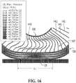
- An example of a corresponding finite-element model of an embodiment of the non-pneumatic tire 110 comprising the annular beam 130 including the shear band 131 of Figure 14 , the spokes 142 1 -142 T and the hub 120is shown in Figure 16 .
- the non-pneumatic tire 110has dimensions 20.5 x 25 - a size used in the construction industry, with the outer diameter D TO of around 1.5 meters.
- Figure 17provides the principle strains in the annular beam 130 comprising the shear band 131 of Figure 16 . Maximum elastomer strains are about 0.09 (9%) which is well
- Figure 17further shows the contact pressure profile through the length Lc of the contact patch 125 of the non-pneumatic tire of Figure 16 for various laminate configurations and for an isotropic configuration of the shear band 131 of the annular beam 130.
- the pressure profilebecomes more uniform.
- E1 and E2increases, the pressure becomes progressively more uniform.
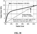
- certain elastomeric materialsmay exhibit favorable non-linear stress vs. strain characteristics.
- a choicemay be made of a material having a very non-linear material behavior, for which the secant modulus decreases with increasing strain.
- the "modulus”is the initial slope of the stress vs. strain curve, often termed "Young's modulus” or “tensile modulus.”
- materialscan be used that have a high Young's modulus that is much greater than their secant modulus at 100% strain, which is often termed "the 100% modulus.”
- the "secant modulus”is the tensile stress divided by the tensile strain for any given point on the tensile stress vs. tensile strain curve measured per ISO 527-1/-2. This nonlinear behavior provides efficient load carrying during normal operation, yet enables impact loading and large local deflections without generating high stresses.
- thermoset and thermoplastic polyurethaneshave this material behavior.
- An example of such a favorable materialis shown in Figure 18 .
- the measured stress vs. strain curve of COIM's PET-95A, with curative MCDEA,has a Young's modulus of 205 MPa.
- the secant modulus at 100% strainis only 19 MPa.
- Thismay be a favorable attribute in some embodiments; when following the design principles earlier disclosed, the tire normally operates in the 5 to 9% strain region. In this region, the material is moderately stiff and the slope of the stress vs. strain curve is fairly constant. However, if local deformation occurs due to road hazards or impacts, the material is capable of large strains, without generation of high stresses. This minimizes vehicle shock loading, and enhances tire durability.
- Elastomersare often used in areas of high imposed strains. As such, in some application, testing protocol typically focuses on the performance at high strains, such as 100%, 200%, or more.
- Mechanical designs that carry load in tension and bendingtypically do not use one homogeneous elastomer - they employ reinforcements as well.
- Some embodiments of the annular beam 130opens this new design space by leveraging this material non-linearity with a favorable mechanical design.
- the wheel 100iincluding its annular beam 130, may be implemented in various other ways in other embodiments.
- the annular beam 130may be designed based on principles discussed in U.S. Patent Application Publication 2014/0367007 , in order to achieve the homogeneous contact pressure along the length Lc of the contact patch 125 of the wheel 100i with the ground.
- the use of multiple elastomerscan be combined with a more complex geometry such that the resulting performance is superior to that which could be obtained by using either technology by itself.
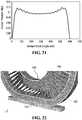
- the shear band 130comprises an outer rim 133, an inner rim 135, and a plurality of openings 156 1 -156 N between the outer rim 133 and the inner rim 133 in addition to including the layers 132 1 -132 N of the different elastomeric materials M 1 -M E .
- the shear band 131comprises a plurality of interconnecting members 137 1 -137 P that extend between the outer rim 133 and the inner rim 135 and are disposed between respective ones of the openings 156 1 -156 N .
- the interconnecting members 137 1 -137 Pmay be referred to as "webs” such that the shear band 131 may be viewed as being “web-like” or "webbing".
- the shear band 131comprises intermediate rims 151, 153 between the outer rim 133 and the inner rim 135 such that the openings 156 1 -156 N and the interconnecting members 137 1 -137 P are arranged into three circumferential rows between adjacent ones of the rims 133, 151, 153, 135.
- the shear band 131, including the openings 156 1 -156 N and the interconnecting members 137 1 -137 Pmay be arranged in any other suitable way in other embodiments.
- the openings 156 1 -156 N of the shear band 131help the shear band 131 to deflect predominantly by shearing at the contact patch 125 under the loading on the wheel 100i.
- the openings 156 1 -156 Nextend from the inboard lateral side 147 to the outboard lateral side 149 of the non-pneumatic tire 110. That is, the openings 156 1 -156 N extend laterally though the shear band 131 in the axial direction of the wheel 100i.
- the openings 156 1 -156 Nmay extend laterally without reaching the inboard lateral side 147 and/or the outboard lateral side 149 of the non-pneumatic tire 110 in other embodiments.
- the openings 156 1 -156 Nmay have any suitable shape.
- a cross-section of each of the openings 156 1 -156 Nis circular.
- the cross-section of each of the openings 156 1 -156 Nmay be shaped differently in other examples (e.g., polygonal, partly curved and partly straight, etc.). In some cases, different ones of the openings 156 1 -156 N may have different shapes. In some cases, the cross-section of each of the openings 156 1 -156 N may vary in the axial direction of the wheel 100i.
- the openings 156 1 -156 Nmay be tapered in the axial direction of the wheel 100i such that their cross-section decreases inwardly axially (e.g., to help minimize debris accumulation within the openings 156 1 -156 N ).
- the shear band 131 of the annular beam 130comprises both (1) the openings 156 1 -156 N and (2) the layers 132 1 -132 N of the different elastomeric materials M 1 -M E .
- thermoset polyurethanes and thermoplastic polyurethaneshave a wide processing and optimization window (e.g., modulus values between 10 MPa and 300 MPa being readily assessable)
- the physicsmay demand a very large bending stiffness and a very low shear stiffness, if a long contact patch of low, homogenous pressure is desired, and combining the openings 156 1 -156 N and the layers 132 1 -132 N of the different elastomeric materials M 1 -M E may allow to achieve desired effects.
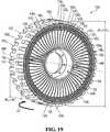
- Figure 20shows a finite-element model of an embodiment of the non-pneumatic tire 110 having these combined technologies.
- a webbing geometry and laminate configurationhave been designed to give about a 0.1 MPa contact pressure, through a length of 600 mm.
- the length Lc of the contact patch 125 of the embodiment of Figure 20represents a large percentage of the radius of the tire, which is 750 mm.
- the contact pressure profile through the length Lc of the contact patch 125 of the non-pneumatic tire of Figure 20is shown in Figure 21 .
- the inventorhas used a deformable ground, corresponding to the stiffness of clay. This more fully represents the actual usage of such a tire in an off-road condition.
- the wheel 100iincluding its non-pneumatic tire 110, may enable a design space that may not be readily possible with pneumatic tires.
- the wheel 100imay be designed to be relatively narrow yet have a high load carrying capacity and a long contact patch.
- the wheel 100imay be such that (1) a ratio W T /D TO of the width W T of the non-pneumatic tire 110 over the outer diameter D TO of the non-pneumatic tire 110 is no more than 0.1 and (2) a ratio D H /D TO of the diameter of the hub 120 over the outer diameter D TO of the non-pneumatic tire 110 is no more than 0.5, namely:
- the ratio W T /D TO of the width W T of the non-pneumatic tire 110 over the outer diameter D TO of the non-pneumatic tire 110may be less than 0.1, in some cases no more than 0.08, in some cases no more than 0.06, and in some cases no more than 0.04, and/or the ratio D H /D TO of the diameter of the hub 120 over the outer diameter D TO of the non-pneumatic tire 110 may be less than 0.5, in some cases no more than 0.4, and in some cases no more than 0.3.
- the wheel 100imay be such that a ratio L c /R TO of the length L c of the contact patch 125 of the non-pneumatic tire 110 at the design load over an outer radius R TO of the non-pneumatic tire 110 (i.e., half of the outer diameter D TO of the non-pneumatic tire 110) is at least 0.4, in some cases at least 0.5, in some cases at least 0.6, in some cases at least 0.7, in some cases at least 0.8, in some cases at least 0.9, and in some cases even more (e.g., 1 or more).
- W T120 mm
- the equilibrium curve mechanics of both radial and bias tiresare such that a width of 120 mm would result in a maximum sidewall height of only about 120 mm. This limits the contact patch length as well as the ability of the tire to absorb energy when traversing uneven terrain.
- the length Lc of the contact patch 125may approach or be larger than the outer radius of the non-pneumatic tire 110 and there is a larger distance between the tire outer diameter D TO and the hub 120.
- the load carrying capacity of the non-pneumatic tire 110can be quite large.
- the non-pneumatic tire 110may comprise other components in other embodiments.
- the tread 150may comprise a reinforcing layer 170 disposed within its elastomeric material 160 (e.g., rubber) and extending in the circumferential direction of the wheel 100i.
- the reinforcing layer 170may comprise a layer of reinforcing cables that are adjacent to one another and extend generally in the circumferential direction of the wheel 100i.
- each of the reinforcing cablesmay be a cord including a plurality of strands (e.g., textile fibers or metallic wires).
- each of the reinforcing cablesmay be another type of cable and may be made of any material suitably flexible along the cable's longitudinal axis (e.g., fibers or wires of metal, plastic or composite material).
- the reinforcing layer 170may comprise a layer of reinforcing fabric.
- the reinforcing fabriccomprises thin pliable material made usually by weaving, felting, knitting, interlacing, or otherwise crossing natural or synthetic elongated fabric elements, such as fibers, filaments, strands and/or others, such that some elongated fabric elements extend transversally to the circumferential direction of the wheel 100i to have a reinforcing effect in that direction.
- the reinforcing fabricmay comprise a ply of reinforcing woven fibers (e.g., nylon fibers or other synthetic fibers).
- the reinforcing layer 170 of the tread 150may be substantially inextensible in the circumferential direction of the wheel 100i.
- the non-pneumatic tire 110may thus be such that its annular beam 130 is free of any substantially inextensible reinforcing layer running in its circumferential direction while its tread 150 includes the reinforcing layer 170 that may be substantially inextensible in its circumferential direction.
- the tread 150 including the reinforcing layer 170may be provided in any suitable way.
- the tread 150may be manufactured separately from the annular beam 130 and then affixed to the annular beam 130.
- the tread 150may be manufactured by arranging one or more layers of its elastomeric material 160 (e.g., rubber) and its reinforcing layer 170 into a mold and molding them (e.g., compression molding them) into an annular configuration of the tread 150.
- the tread 150may then be affixed to the annular beam 130 in any suitable way.
- the tread 150may be expanded to fit about the annular beam 130 and then contracted to become attached to the annular beam 130.
- thismay be achieved by a coefficient of thermal expansion of the reinforcing layer 170 of the tread 150 allowing the reinforcing layer 170 to expand for stretching the elastomeric material 160 of the tread 150 in order to fit the tread 150 around the annular beam 130 and then to contract for attaching the tread 150 to the annular beam 130.
- the tread 150may be affixed to the annular beam 130 in any other suitable manner in other examples (e.g., including by using an adhesive to adhesively bond the tread 150 and the annular beam 130).
- wheel 100iis part of the construction vehicle 10
- a wheel constructed according to principles discussed hereinmay be used as part of other vehicles or other machines in other embodiments.
- an all-terrain vehicle (ATV) 210may comprise wheels 220 1 -220 4 constructed according to principles discussed herein in respect of the wheel 100i.
- the ATV 210is a small open vehicle designed to travel off-road on a variety of terrains, including roadless rugged terrain, for recreational, utility and/or other purposes.
- the ATV 210comprises a frame 212, a powertrain 214, a steering system 216, a suspension 218, the wheels 220 1 -220 4 , a seat 222, and a user interface 224, which enable a user of the ATV 210 to ride the ATV 210 on the ground.
- the steering system 216is configured to enable the user to steer the ATV 210 on the ground.
- the steering system 216comprises a steering device 228 that is operable by the user to direct the ATV 210 along a desired course on the ground.
- the steering device 228comprises handlebars.
- the steering device 228may comprise a steering wheel or any other steering component that can be operated by the user to steer the ATV 210 in other embodiments.
- the steering system 216responds to the user interacting with the steering device 228 by turning respective ones of the wheels 220 1 -220 4 to change their orientation relative to the frame 212 of the ATV 210 in order to cause the ATV 210 to move in a desired direction.
- front ones of the wheels 220 1 -220 4are turnable in response to input of the user at the steering device 228 to change their orientation relative to the frame 212 of the ATV 210 in order to steer the ATV 210 on the ground. More particularly, in this example, each of the front ones of the wheels 220 1 -220 4 is pivotable about a steering axis 230 of the ATV 210 in response to input of the user at the steering device 228 in order to steer the ATV 210 on the ground. Rear ones of the wheels 220 1 -220 4 are not turned relative to the frame 212 of the ATV 210 by the steering system 216.
- the suspension 218is connected between the frame 212 and the wheels 220 1 -220 4 to allow relative motion between the frame 122 and the wheels 220 1 -220 4 as the ATV 210 travels on the ground.
- the suspension 218enhances handling of the ATV 210 on the ground by absorbing shocks and helping to maintain traction between the wheels 20 1 -20 4 and the ground.
- the suspension 218may comprise an arrangement of springs and dampers.
- a springmay be a coil spring, a leaf spring, a gas spring (e.g., an air spring), or any other elastic object used to store mechanical energy.
- a dampermay be a fluidic damper (e.g., a pneumatic damper, a hydraulic damper, etc.), a magnetic damper, or any other object which absorbs or dissipates kinetic energy to decrease oscillations.
- a single devicemay itself constitute both a spring and a damper (e.g., a hydropneumatic, hydrolastic, or hydragas suspension device).
- the seat 222is a straddle seat and the ATV 210 is usable by a single person such that the seat 222 accommodates only that person driving the ATV 210.
- the seat 222may be another type of seat, and/or the ATV 210 may be usable by two individuals, namely one person driving the ATV 210 and a passenger, such that the seat 222 may accommodate both of these individuals (e.g., behind one another or side-by-side) or the ATV 210 may comprise an additional seat for the passenger.
- the ATV 210may be a side-by-side ATV, sometimes referred to as a "utility terrain vehicle” or "utility task vehicle” (UTV).
- UUVutility task vehicle
- the wheels 220 1 -220 4engage the ground to provide traction to the ATV 210. More particularly, in this example, the front ones of the wheels 220 1 -220 4 provide front traction to the ATV 10 while the rear ones of the wheels 220 1 -220 4 provide rear traction to the ATV 10.
- Each wheel 220i of the ATV 210may be constructed according to principles described herein in respect of the wheel 100i, notably by comprising a non-pneumatic tire 234 and a hub 232 that may be constructed according to principles described herein in respect of the non-pneumatic tire 110 and the hub 120.
- the non-pneumatic tire 234comprises an annular beam 236 and an annular support 241 that may be constructed according principles described herein in respect of the annular beam 130 and the annular support 140.
- the annular beam 236comprises a shear band 239 comprising a plurality of layers 232 1 -232 N of different elastomeric materials M 1 -M E and the annular support 241 comprises spokes 242 1 -242 J that may be constructed according to principles described herein in respect of the shear band 131 and the spokes 142 1 -142 T .
- a motorcycle 410may comprise a front wheel 420 1 and a rear wheel 420 2 constructed according to principles discussed herein in respect of the wheel 100i.
- a wheel constructed according to principles discussed herein in respect of the wheel 100imay be used as part of an agricultural vehicle (e.g., a tractor, a harvester, etc.), a material-handling vehicle, a forestry vehicle, or a military vehicle.
- an agricultural vehiclee.g., a tractor, a harvester, etc.
- a material-handling vehiclee.g., a forestry vehicle, or a military vehicle.
- a wheel constructed according to principles discussed herein in respect of the wheel 100imay be used as part of a road vehicle such as an automobile or a truck.
- a wheel constructed according to principles discussed herein in respect of the wheel 100imay be used as part of a lawnmower (e.g., a riding lawnmower or a walk-behind lawnmower).
- a lawnmowere.g., a riding lawnmower or a walk-behind lawnmower.
- annular devicessuch as, for instance, tracks for vehicles and/or conveyor belts, may comprise an annular beam constructed according to principles discussed herein in respect of the annular beam 130.
Landscapes
- Engineering & Computer Science (AREA)
- Mechanical Engineering (AREA)
- Tires In General (AREA)
Description
- The invention generally relates to non-pneumatic tires (NPTs), such as for vehicles (e.g., industrial vehicles such as construction vehicles; all-terrain vehicles (ATVs); agricultural vehicles; automobiles and other road vehicles; etc.) and/or other machines.
- Wheels for vehicles and other machines may comprise non-pneumatic tires (sometimes referred to as NPTs) instead of pneumatic tires.
- Pneumatic tires are market leaders across a wide variety of size, speed, and load requirements. For example, radial pneumatic tires are found on automotive tires of 0.6 meter diameter that carry 0.5 metric tons, and also on tires used in mining operations of 4 meter diameter that carry 50 metric tons. Pneumatic tires are thus scalable.
- Pneumatic tires offer high load capacity per unit mass, along with a large contact area and relatively low vertical stiffness. High contact area results in the ability to both efficiently generate high tangential forces and obtain excellent wear characteristics. However, pneumatic tires are also prone to flats.
- Non-pneumatic tires offer flat-free operation, yet generally contain some compromise. For various reasons, non-pneumatic tires do not have a predominant market share in various industries because they tend to be expensive, heavy, have a poor ride quality, have limited speed capability under heavy load, and/or have lower traction potential, compared to pneumatic tires. For example, in construction and other field with large tires, in the common dimension 20.5 inch x 25 inch (20.5 inches wide, 25 inch diameter wheel), currently available non-pneumatic tires weighs around 2000 lbs., whereas a pneumatic tire and steel wheel only weigh around 650 lbs.
- Non-pneumatic tires in this size are usually solid, with the addition of circular cutouts in the tire sidewall to reduce the compressive stiffness of the structure. Because of this solid construction, heat build-up is problematic. Elastomers are generally good insulators, and therefore such structures tend to retain heat. This reduces their utility in practical use in some cases.
- Other annular devices, such as, for instance, tracks for vehicles and/or conveyor belts, may in some cases be affected by similar considerations.
- For these and other reasons, there is a need to improve non-pneumatic tires and other annular devices.
- As an example, International Application Publication
WO2008/045098 discloses a non-pneumatic tire that includes an annular beam comprising a composite shear layer that has different materials and substantially inextensible membranes radially inward and outward of the composite shear layer. - Another example disclosed in
U.S. Patent Application Publication 2007/267116 discloses a non-pneumatic tire that includes an annular beam comprising a shear layer and substantially inextensible membranes radially inward and outward of the shear layer. - An example of
U.S. Patent 6,450,222 discloses a non-pneumatic tire that is solid, mounted on a rigid rim, and made up of annular portions formed of different materials, such that the tire deforms at its contact patch under load by compression. US2014367007 discloses a non-pneumatic tire comprising an annular beam made of elastomer, a central hub and a plurality of web spokes extending axially across and radially inward from the annular beam, and connecting the annular beam to the central hub.- A non-pneumatic tire according to the present invention is defined in
claim 1. Preferred embodiments are defined in the dependent claims. - The invention will now become apparent to those of ordinary skill in the art upon review of the following description of embodiments of the invention in conjunction with the accompanying drawings.
- A detailed description of embodiments is provided below, by way of example only, with reference to the accompanying drawings, in which:
Figure 1 shows an example of a vehicle comprising wheels that comprises non-pneumatic tires in accordance with an embodiment of the invention;Figure 2 shows a perspective view of a wheel comprising a non-pneumatic tire;Figure 3 shows a side-elevation view of the wheel and a contact patch of the wheel;Figure 4 shows a perspective view of an annular beam of the non-pneumatic tire;Figure 5 shows a cross section of the annular beam;Figures 6 to 9 show a side-elevation view of various embodiments of an annular support of the non-pneumatic tire;Figure 10 shows an example of a spin casting process that may be used to make the non-pneumatic tire;Figure 11 shows a cross section view of an example of a straight beam that comprises a laminate configuration of elastomer materials;Figure 12 shows a side elevation view of the straight beam ofFigure 11 when simply supported by two parallel contact surfaces and subjected to a constant pressure P;Figure 13 shows a graph showing an example of a relationship between a ratio of beam deflections due to shear and due to bending and a modulus of elasticity of an elastomeric material;Figure 14 shows a finite-element model of an embodiment of the annular beam loaded between two parallel contact surfaces;Figure 15 shows analytical solutions of a contact pressure distribution along a contact length of a contact patch of an embodiment of the annular beam comprising the laminate configuration and an embodiment of an annular beam made of an isotropic elastomer;Figure 16 shows a finite-element model of an embodiment of the non-pneumatic tire comprising the annular beam ofFigure 14 and subjected to a vertical load on a rigid contact surface;Figure 17 shows analytical solutions of a contact pressure distribution along the contact length of the contact patch of an embodiment of the annular beam of the non-pneumatic tire ofFigure 16 comprising different laminate configurations and an embodiment of an annular beam comprising an isotropic elastomer;Figure 18 shows an example of a thermoplastic polyurethane exhibiting non-linear stress vs. strain characteristics;Figure 19 shows a perspective view of the wheel comprising the non-pneumatic tire in accordance with another embodiment of the invention;Figure 20 shows a finite-element model of the non-pneumatic tire ofFigure 19 subjected to a vertical load on a deformable contact surface;Figure 21 shows analytical solutions of a contact pressure distribution along a contact length of the contact patch of the non-pneumatic tire ofFigure 20 ;Figure 22 shows a finite-element model of the non-pneumatic tire ofFigure 20 ;Figure 23 shows a partial cross-sectional view of the non-pneumatic tire that comprises a tread comprising a reinforcing layer in accordance with another embodiment of the invention;Figures 24 and25 show an example of another vehicle comprising wheels that comprise non-pneumatic tires in accordance with another embodiment of the invention; andFigure 26 shows an example of another vehicle comprising wheels that comprises non-pneumatic tires in accordance with another embodiment of the invention.Figure 1 shows an example of avehicle 10 comprising a plurality of wheels 1001-1004 In this embodiment, thevehicle 10 is an industrial vehicle. Theindustrial vehicle 10 is a heavy-duty vehicle designed to travel off-road to perform industrial work using a work implement 44. In this embodiment, theindustrial vehicle 10 is a construction vehicle for performing construction work using the work implement 44. More particularly, in this embodiment, theconstruction vehicle 10 is a loader (e.g., a skid-steer loader). Theconstruction vehicle 10 may be a bulldozer, a backhoe loader, an excavator, a dump truck, or any other type of construction vehicle in other embodiments. In this example, theconstruction vehicle 10 comprises aframe 12, apowertrain 14, asteering system 16, asuspension 18, the wheels 1001-1004, and anoperator cabin 22, which enable a user, i.e., an operator, of theconstruction vehicle 10 to move thevehicle 10 on the ground and perform work using the work implement 44. Theconstruction vehicle 10 has a longitudinal direction, a widthwise direction, and a height direction.- In this embodiment, as further discussed later, the wheels 1001-1004 are non-pneumatic (i.e., airless) and may be designed to enhance their use and performance and/or use and performance of the
construction vehicle 10, including, for example, by having a high load-carrying capacity while being relatively lightweight. - The
powertrain 14 is configured for generating motive power and transmitting motive power to respective ones of the wheels 1001-1004 to propel theconstruction vehicle 10 on the ground. To that end, thepowertrain 14 comprises aprime mover 26, which is a source of motive power that comprises one or more motors. For example, in this embodiment, theprime mover 26 comprises an internal combustion engine. In other embodiments, theprime mover 26 may comprise another type of motor (e.g., an electric motor) or a combination of different types of motor (e.g., an internal combustion engine and an electric motor). Theprime mover 26 is in a driving relationship with one or more of the wheels 1001-1004. That is, thepowertrain 14 transmits motive power generated by theprime mover 26 to one or more of the wheels 1001-1004 (e.g., via a transmission and/or a differential) in order to drive (i.e., impart motion to) these one or more of the wheels 1001-1004. - The
steering system 16 is configured to enable the operator to steer theconstruction vehicle 10 on the ground. To that end, thesteering system 16 comprises asteering device 28 that is operable by the operator to direct theconstruction vehicle 10 along a desired course on the ground. Thesteering device 28 may comprise a steering wheel or any other steering component (e.g., a joystick) that can be operated by the operator to steer theconstruction vehicle 10. Thesteering system 16 responds to the operator interacting with thesteering device 28 by turning respective ones of the wheels 1001-1004 to change their orientation relative to part of theframe 12 of theconstruction vehicle 10 in order to cause thevehicle 10 to move in a desired direction. In this example, a front frame member 231 carrying front ones of the wheels 1001-1004 is turnable in response to input of the operator at thesteering device 28 to change its orientation and thus the orientation of the front ones of the wheels 1001-1004 relative to a rear frame member 232 of theconstruction vehicle 10 in order to steer theconstruction vehicle 10 on the ground. - The
suspension 18 is connected between theframe 12 and the wheels 1001-1004 to allow relative motion between theframe 12 and the wheels 1001-1004 as theconstruction vehicle 10 travels on the ground. For example, thesuspension 18 may enhance handling of theconstruction vehicle 10 on the ground by absorbing shocks and helping to maintain traction between the wheels 1001-1004 and the ground. Thesuspension 18 may comprise an arrangement of springs and dampers. A spring may be a coil spring, a leaf spring, a gas spring (e.g., an air spring), or any other elastic object used to store mechanical energy. A damper (also sometimes referred to as a "shock absorber") may be a fluidic damper (e.g., a pneumatic damper, a hydraulic damper, etc.), a magnetic damper, or any other object which absorbs or dissipates kinetic energy to decrease oscillations. In some cases, a single device may itself constitute both a spring and a damper (e.g., a hydropneumatic, hydrolastic, or hydragas suspension device). - The
operator cabin 22 is where the operator sits and controls theconstruction vehicle 10. More particularly, theoperator cabin 22 comprises auser interface 70 including a set of controls that allow the operator to steer theconstruction vehicle 10 on the ground and operate the work implement 44. Theuser interface 70 also comprises an instrument panel (e.g., a dashboard) which provides indicators (e.g., a speedometer indicator, a tachometer indicator, etc.) to convey information to the operator. - The wheels 1001-1004 engage the ground to provide traction to the
construction vehicle 10. More particularly, in this example, the front ones of the wheels 1001-1004 provide front traction to theconstruction vehicle 10 while the rear ones of the wheels 1001-1004 provide rear traction to theconstruction vehicle 10. - Each wheel 100i comprises a
non-pneumatic tire 110 for contacting the ground and ahub 120 for connecting the wheel 100i to an axle of thevehicle 10. Thenon-pneumatic tire 110 is a compliant wheel structure that is not supported by gas (e.g., air) pressure and that is resiliently deformable (i.e., changeable in configuration) as the wheel 100i contacts the ground. With additional reference toFigure 2 , the wheel 100i has an axial direction defined by an axis ofrotation 180 of the wheel 100i (also referred to as a "Y" direction), a radial direction (also referred to as a "Z" direction), and a circumferential direction (also referred to as a "X" direction). These axial, radial and circumferential directions also apply to components of the wheel 100i, including thenon-pneumatic tire 110. The wheel's equatorial plane is that plane defined by the x - z axes, while the wheel's cross section is that plane defined by the y - z axes. The wheel 100i has an outer diameter Dw and a width Ww. It comprises an inboardlateral side 147 for facing a center of the vehicle in the widthwise direction of the vehicle and an outboardlateral side 149 opposite the inboardlateral side 147. As shown inFigure 3 , when it is in contact with the ground, the wheel 100i has an area ofcontact 125 with the ground, which may be referred to as a "contact patch" of the wheel 100i with the ground. Thecontact patch 125 of the wheel 100i, which is a contact interface between thenon-pneumatic tire 110 and the ground, has a length Lc in the circumferential direction of the wheel 100i and a width Wc in the axial direction of the wheel 100i. - The
non-pneumatic tire 110 comprises anannular beam 130 and anannular support 140 that is disposed between theannular beam 130 and thehub 120 of the wheel 100i and configured to support loading on the wheel 100i as the wheel 100i engages the ground. In this embodiment, thenon-pneumatic tire 110 is tension-based such that theannular support 140 is configured to support the loading on the wheel 100i by tension. That is, under the loading on the wheel 100i, theannular support 140 is resiliently deformable such that alower portion 127 of theannular support 140 between the axis ofrotation 180 of the wheel 100i and thecontact patch 125 of the wheel 100i is compressed and anupper portion 129 of theannular support 140 above the axis ofrotation 180 of the wheel 100i is in tension to support the loading. - The
annular beam 130 of thenon-pneumatic tire 1 10 is configured to deflect under the loading on the wheel 100i at thecontact patch 125 of the wheel 100i with the ground. In this embodiment, theannular beam 130 is configured to deflect such that it applies a homogeneous contact pressure along the length Lc of thecontact patch 125 of the wheel 100i with the ground. - More particularly, in this embodiment, the
annular beam 130 comprises ashear band 131 configured to deflect predominantly by shearing at thecontact patch 125 under the loading on the wheel 100i. That is, under the loading on the wheel 100i, theshear band 131 deflects significantly more by shearing than by bending at thecontact patch 125. Theshear band 131 is thus configured such that, at a center of thecontact patch 125 of the wheel 100i in the circumferential direction of the wheel 100i, a shear deflection of theannular beam 130 is significantly greater than a bending deflection of theannular beam 130. For example, in some embodiments, at the center of thecontact patch 125 of the wheel 100i in the circumferential direction of the wheel 100i, a ratio of the shear deflection of theannular beam 130 over the bending deflection of theannular beam 130 may be at least 1.2, in some cases at least 1.5, in some cases at least 2, in some cases at least 3, in some cases at least 5, in some cases at least 7, and in some cases even more . For instance, in some embodiments, theannular beam 130 may be designed based on principles discussed inU.S. Patent Application Publication 2014/0367007 , in order to achieve the homogeneous contact pressure along the length Lc of thecontact patch 125 of the wheel 100i with the ground. - In this embodiment, the
shear band 131 of theannular beam 130 comprises a plurality of layers 1321-132N of different elastomeric materials M1-ME. The layers 1321-132N of the different elastomeric materials M1-ME extend in the circumferential direction of the wheel 100i and are disposed relative to one another in the radial direction of the wheel 100i. As further discussed later, in some embodiments, this laminate construction of the different elastomeric materials M1-ME may enhance performance of the wheel 100i, including behavior of itscontact patch 125 and may also help theannular beam 130 to have a high load to mass ratio, yet keep the simplicity of an elastomer structure, with no need for inextensible membranes or other composites or reinforcing elements. In this example, the layers 1321-132N of the different elastomeric materials M1-ME are seven layers, namely the layers 1321-1327 and the different elastomeric materials M1-ME are two different elastomeric materials, namely the elastomeric materials M1, M2. The layers 1321-132N and/or the elastomeric materials M1-ME may be present in any other suitable numbers in other examples. - More particularly, in this embodiment, the
layers layers layers annular beam 130 are thus arranged such that the different elastomeric materials M1, M2 alternate in the radial direction of the wheel 100i. - For instance, in this embodiment, the
shear band 131 comprises thelayer 1321, composed of elastomeric material M1, lying on a radially inward extent of theshear band 131. Theshear band 131 comprises thelayer 1322, composed of elastomeric material M2, lying on a radially outward extent of thelayer 1321. Theshear band 131 comprises thelayer 1323, composed of elastomeric material M1, lying on a radially outward extent of thelayer 1322. In this embodiment, a laminate configuration of the elastomeric material of theshear band 131 is M1 / M2 / M1. In other embodiments, the laminate configuration of the elastomeric material of theshear band 131 may be repeated any number of times. For example, inFigures 4 and 5 , the laminate configuration of the elastomeric material of theshear band 131 from an inward to an outward extent of theshear band 131 is M1 / M2 / M1 / M2 / M1 / M2 / M1. Each one of the layers 1321-1327 is composed of a homogeneous elastomer in this example. - The different elastomeric materials M1 and M2 may differ in any suitable way. For example, in some embodiments, a stiffness of the elastomeric material M1 may be different from a stiffness of the elastomeric material M2. That is, the elastomeric material M1 may be stiffer or less stiff than the elastomeric material M2. For instance, a modulus of elasticity E1 (i.e., Young's modulus) of the elastomeric material M1 may be different from a modulus of elasticity E2 of the elastomeric material M2. A modulus of elasticity herein is Young's tensile modulus of elasticity measured per ISO 527-1/-2, and "Young's Modulus," "tensile modulus," and "modulus" may be used interchangeably herein. For example, in some embodiments, the modulus of elasticity E1 of the elastomeric material M1 may be greater than the modulus of elasticity E2 of the elastomeric material M2. For instance, in some embodiments, a ratio E1/E2 of the modulus of elasticity E1 of the elastomeric material M1 over the modulus of elasticity E2 of the elastomeric material M2 may be at least 2, in some cases at least 3, in some cases at least 4, in some cases at least 5, in some cases at least 6, in some cases at least 7, in some cases at least 8, and in some cases even more.
- For example, in some embodiments, the modulus of elasticity E1 of the elastomeric material M1 may be at least 150 MPa, and in some cases at least 200 MPa or even more, while the modulus of elasticity E2 of the elastomeric material M2 may be no more than 50 MPa, and in some cases no more than 30 MPa or even less. As will be disclosed, such a modulus definition can be engineered to give a beam particular bending and shear properties that are favorable for use in the
non-pneumatic tire 110. Figure 5 shows a cross section AA of theshear band 131 of theannular beam 130 where the layers 1321-1327 of theannular beam 131 are shown. In some embodiments, such as the embodiment ofFigures 4 and 5 , theinnermost layer 1321 and theoutermost layer 1327 of theshear band 131 may be composed of the elastomeric material M1 with the modulus of elasticity E1 higher than the modulus of elasticity E2 of the elastomeric material M2. That is, in this embodiment, the elastomeric material with the higher modulus of elasticity may be used at the inner and outer radial extents of theshear band 131 of theannular beam 130.- In other embodiments, other repeating or non-repeating laminate configurations of the elastomeric material of the
shear band 131 comprising the elastomeric material with the higher modulus of elasticity at the inner and outer radial extents of theshear band 131 may be used. That is, in these embodiments, multiple layers composed of multiple elastomeric materials may be used with or without symmetry of the laminate configuration of the elastomeric material of theshear band 131 and theshear band 131 may comprise at least three elastomeric materials in a laminate configuration. For example, the laminate configuration of the elastomeric material of theshear band 131 from an inward to an outward extent of theshear band 131 may be of the type M1 / M2 / M3 / M2 / M1 or M1 / M2 / M3 / M1 or any other combination thereof, where M3 is an elastomeric material having a modulus of elasticity E3 different from the modulus of elasticity E1 of the elastomeric material M1 and different from the modulus of elasticity E2 of the elastomeric material M2. - In some embodiments, and with further reference to
Figures 4 and 5 , each one of the layers 1321-1327 of theshear band 131 extends from the inboardlateral side 147 to the outboardlateral side 149 of thenon-pneumatic tire 110. That is, each one of the layers 1321-1327 of theshear band 131 extends laterally through theshear band 131 in the axial direction of thewheel 100. - The different elastomeric materials M1-ME may include any other suitable elastomers in various embodiments. For example, in some embodiments, suitable elastomeric materials include thermoplastic and thermoset polyurethane and thermoplastic and thermoset rubbers.
- In this embodiment, the
annular beam 130 is free of (i.e., without) a substantially inextensible reinforcing layer running in the circumferential direction of the wheel 100i (e.g., a layer of metal, composite (e.g., carbon fibers, other fibers), and/or another material that is substantially inextensible running in the circumferential direction of the wheel 100i). In that sense, theannular beam 130 may be said to be "unreinforced". Thus, in this embodiment, useful behavior of the wheel 100i, including deflection and behavior of itscontact patch 125, may be achieved without any substantially inextensible reinforcing layer running in the circumferential direction of the wheel 100i, which may help to reduce the weight and cost of the wheel 100i. - In this embodiment, the
non-pneumatic tire 110 comprises atread 150 for enhancing traction between thenon-pneumatic tire 110 and the ground. Thetread 150 is disposed about an outerperipheral extent 146 of theannular beam 130, in this case about theoutermost layer 1327 of theshear band 131 composed of the elastomeric material M1. More particularly, in this example thetread 150 comprises atread base 151 that is at the outerperipheral extent 146 of theannular beam 130 and a plurality of tread projections 1521-152T that project from thetread base 151. Thetread 150 may be implemented in any other suitable way in other embodiments (e.g., may comprise a plurality of tread recesses, etc.). - The
annular support 140 is configured to support the loading on the wheel 100i as the wheel 100i engages the ground. As mentioned above, in this embodiment, theannular support 140 is configured to support the loading on the wheel 100i by tension. More particularly, in this embodiment, theannular support 140 comprises a plurality of support members 1421-142T that are distributed around thenon-pneumatic tire 110 and resiliently deformable such that, under the loading on the wheel 100i, lower ones of the support members 1421-142T in thelower portion 127 of the annular support 140 (between the axis ofrotation 180 of the wheel 100i and thecontact patch 125 of the wheel 100i) are compressed and bend while upper ones of the support members 1421-142T in theupper portion 129 of the annular support 140 (above the axis ofrotation 180 of the wheel 100i) are tensioned to support the loading. As they support load by tension when in theupper portion 129 of theannular support 140, the support members 1421-142T may be referred to as "tensile" members. - In this embodiment, the support members 1421-142T are elongated and extend from the
annular beam 130 towards thehub 120 generally in the radial direction of the wheel 100i. In that sense, the support members 1421-142T may be referred to as "spokes" and theannular support 140 may be referred to as a "spoked" support. - More particularly, in this embodiment, each spoke 142i extends from an inner
peripheral surface 148 of theannular beam 130 towards thehub 120 generally in the radial direction of the wheel 100i and from a firstlateral end 155 to a secondlateral end 157 in the axial direction of the wheel 100i. In this case, the spoke 142i extends in the axial direction of the wheel 100i for at least a majority of a width WT of thenon-pneumatic tire 110, which in this case corresponds to the width Ww of the wheel 100i. For instance, in some embodiments, the spoke 142i may extend in the axial direction of the wheel 100i for more than half, in some cases at least 60%, in some cases at least 80%, and in some cases an entirety of the width WT of thenon-pneumatic tire 110. Moreover, the spoke 142i has a thickness Ts measured between afirst surface face 159 and asecond surface face 161 of the spoke 142i that is significantly less than a length and width of the spoke 142i. - When the wheel 100i is in contact with the ground and bears a load (e.g., part of a weight of the vehicle), respective ones of the spokes 1421-142T that are disposed in the
upper portion 129 of the spoked support 140 (i.e., above the axis ofrotation 180 of the wheel 100i) are placed in tension while respective ones of the spokes 1421-142T that are disposed in thelower portion 127 of the spoked support 140 (i.e., adjacent the contact patch 125) are placed in compression. The spokes 1421-142T in thelower portion 127 of thespoked support 140 which are in compression bend in response to the load. Conversely, the spokes 1421-142T in theupper portion 129 of thespoked support 140 which are placed in tension support the load by tension. - The spokes 1421-142T may be implemented in any other suitable way in other embodiments. For example,
Figures 6 to 9 show various embodiments of the design of the spokes 1421-142T. In the embodiment ofFigure 6 , each spoke 142i extends generally along a straight line in the radial direction of the wheel 100i. In the embodiment ofFigure 7 , each spoke 142i extends generally along a straight line in the radial direction of the wheel 100i, aspoke connector 143 being located between every other pair of successive spokes 142i and connecting two successive spokes 142i. Thespoke connector 143 is substantially perpendicular to the radial direction of the wheel 100i and may be positioned at any distance from thehub 120 . along the radial direction of the wheel 100i. In some embodiment, thespoke connector 143 extends in the axial direction of the wheel 100i for at least a majority of the width WT of thenon-pneumatic tire 110, which in this case corresponds to the width Ww of the wheel 100i. For instance, in some embodiments, thespoke connector 143 may extend in the axial direction of the wheel 100i for more than half, in some cases at least 60%, in some cases at least 80%, and in some cases an entirety of the width WT of thenon-pneumatic tire 110. Moreover, thespoke connector 143 has a thickness Tsc measured between afirst surface face 163 and asecond surface face 165 of thespoke connector 143 that is significantly less than a length and width of thespoke connector 143. In other embodiments, thespoke connector 143 may not be substantially perpendicular to the radial direction of the wheel 100i. In other embodiments, there may be a plurality ofspoke connectors 143 connecting two spokes 142i. In the embodiment ofFigure 8 , each spoke 142i extends generally along a straight line at an angle α or -α in the radial direction of the wheel 100i such that two successive spokes 142i do not extend generally along a straight line at the same angle in the radial direction of the wheel 100i. In the embodiment ofFigure 9 , each spoke 142i extends generally as a curved line along the radial direction of the wheel 100i. Other designs may be possible in other embodiments. - The
non-pneumatic tire 110 has an inner diameter DTI and an outer diameter DTO, which in this case corresponds to the outer diameter Dw of thewheel 100. A sectional height HT of thenon-pneumatic tire 110 is half of a difference between the outer diameter DTO and the inner diameter DTI of thenon-pneumatic tire 110. The sectional height HT of the non-pneumatic tire may be significant in relation to the width WT of thenon-pneumatic tire 110. In other words, an aspect ratio AR of thenon-pneumatic tire 110 corresponding to the sectional height HT over the width WT of thenon-pneumatic tire 110 may be relatively high. For instance, in some embodiments, the aspect ratio AR of thenon-pneumatic tire 110 may be at least 70%, in some cases at least 90%, in some cases at least 110%, and in some cases even more. Also, the inner diameter DTI of thenon-pneumatic tire 110 may be significantly less than the outer diameter DTO of thenon-pneumatic tire 110 as this may help for compliance of the wheel 100i. For example, in some embodiments, the inner diameter DTI of thenon-pneumatic tire 110 may be no more than half of the outer diameter DTO of thenon-pneumatic tire 110, in some cases less than half of the outer diameter DTO of thenon-pneumatic tire 110, in some cases no more than 40% of the outer diameter DTO of thenon-pneumatic tire 110, and in some cases even a smaller fraction of the outer diameter DTO of thenon-pneumatic tire 110. - In this embodiment, the
non-pneumatic tire 110 therefore comprises different tire materials that make up thetire 110, including the elastomeric materials M1-ME of theshear band 131 of theannular beam 130 and a spoke material 145 that makes up at least a substantial part (i.e., a substantial part or an entirety) of the spokes 1421-142T. Thehub 120 comprises a hub material 172 that makes up at least a substantial part of thehub 120. In some embodiments, the hub material 172 may be the same as one of the tire materials, namely one of the elastomeric materials M1-ME of theshear band 131 of theannular beam 130 and the spoke material 145. In other embodiments, the hub material 172 may be different from any of the tire materials, i.e., different from any of the elastomeric materials M1-ME of theshear band 131 of theannular beam 130 and the spoke material 145. For instance, in some embodiments, the spoke material 145 and the hub material 172 may be any one of the elastomeric material M1, M2, M3 or any other elastomeric material that may be comprised in theshear band 131 of theannular beam 130. - In this embodiment, any given material of the wheel 100i, such as any given one of the tire materials (i.e., the elastomeric materials M1-ME of the
shear band 131 of theannular beam 130 and the spoke material 145) and/or the hub material 172 may exhibit a non-linear stress vs. strain behavior. For instance, the spoke material 145 may have a secant modulus that decreases with increasing strain of the spoke material 145. A secant modulus herein is defined as a tensile stress divided by a tensile strain for any given point on a tensile stress vs. tensile strain curve measured per ISO 527-1/-2. The spoke material 145 may have a high Young's modulus that is significantly greater than the secant modulus at 100% strain (a.k.a. "the 100% modulus"). Such a non-linear behavior of the spoke material 145 may provide efficient load carrying during normal operation and enable impact loading and large local deflections without generating high stresses. For instance, the spoke material 145 may allow thenon-pneumatic tire 110 to operate at a low strain rate (e.g., 2% to 5%) during normal operation yet simultaneously allow large strains (e.g., when the wheel 100i engages obstacles) without generating high stresses. This in turn may be helpful to minimize vehicle shock loading and enhance durability of thenon-pneumatic tire 110. - The
non-pneumatic tire 110 may comprise any other arrangement of materials in other embodiments (e.g., different parts of theannular beam 130, different parts of thetread 150, and/or different parts of the spokes 1421-142T may be made of different materials). For example, in some embodiments, different parts of thetread 150, and/or different parts of the spokes 1421-142T may be made of different elastomers. - In this embodiment, the hub material 172 constitutes at least part of the
hub 120. More particularly, in this embodiment, the hub material 172 constitutes at least a majority (e.g., a majority or an entirety) of thehub 120. In this example of implementation, the hub material 172 makes up an entirety of thehub 120. - In this example of implementation, the hub material 172 is polymeric. More particularly, in this example of implementation, the hub material 172 is elastomeric. For example, in this embodiment, the hub material 172 comprises a polyurethane (PU) elastomer. For instance, in some cases, the PU elastomer may be PET-95A commercially available from COIM, cured with MCDEA.
- The hub material 172 may be any other suitable material in other embodiments. For example, in other embodiments, the hub material 172 may comprise a stiffer polyurethane material, such as COIM's PET75D cured with MOCA. In some embodiments, the hub material 172 may not be polymeric. For instance, in some embodiments, the hub material 172 may be metallic (e.g., steel, aluminum, etc.).
- The
hub 120 may comprise one or more additional materials in addition to the hub material 172 in other embodiments (e.g., different parts of thehub 120 may be made of different materials). - For example, in some embodiments, for the
spoked support 140 and thehub 120, various cast polyurethanes of either ether or ester systems may be used when appropriate (e.g. with alternative cure systems such as MOCA). In some examples, a shore hardness in the range of 90A to 75D and/or a Young's modulus between 40 MPA to 2000 MPa may be appropriate. - In some embodiments, the
spoked support 140 and thehub 120 may comprise different materials. For example, thespoked support 140 may comprise a softer material (e.g., with a Young's modulus between 40 MPA to 100 MPA) and thehub 120 may comprise a harder material (e.g., with modulus between 300 to 2000 MPA). - The
tread 150 may comprise anelastomeric material 160. In some examples of implementation, theelastomeric material 160 of thetread 150 may be different from the elastomeric materials M1-ME of theannular beam 130. For example, in some embodiments, theelastomeric material 160 of thetread 150 may be rubber. In other embodiments, theelastomeric material 160 of thetread 150 may be polyurethane or another elastomer. For instance, in some embodiments, thetread 150 may comprise rubber, cast polyurethane or any other suitable elastomer, and may have a Shore hardness of between 60A to 85A, with a Young's modulus between 3 MPa and 20 MPa. Thetread 150 may be provided in any suitable way, such as by molding and/or adhesively bonding theelastomeric material 160 of thetread 150 about theannular beam 130. - The wheel 100i may be manufactured in any suitable way. For example, in some embodiments, the
non-pneumatic tire 110 and/or thehub 120 may be manufactured via centrifugal casting, a.k.a. spin casting, which involves pouring one or more materials of the wheel 100i into amold 200 that rotates about anaxis 202 as shown inFigure 10 . The material(s) is(are) distributed within themold 200 via a centrifugal force generated by the mold's rotation. In some cases, vertical spin casting, in which the mold's axis ofrotation 202 is generally vertical, may be used. In other cases, as shown inFigure 10 , horizontal spin casting, in which the mold's axis ofrotation 202 is generally horizontal, may be used. In some embodiments, horizontal spin casting may be useful for casting the layers 1321-132N of the different elastomeric materials M1-ME of theannular beam 130 in a more controlled manner. Thewheel 100 may be manufactured using any other suitable manufacturing processes in other embodiments. - The wheel 100i may be lightweight. That is, a mass Mw of the wheel 100i may be relatively small. For example, in some embodiments, a ratio Mnormalized of the mass Mw of the wheel 100i in kilograms over the outer diameter Dw of the wheel 100i normalized by the width Ww of the wheel 100i,

- For instance, in some embodiments, the outer diameter of the wheel 100i may be 1.5 m, the width of the wheel 100i may be about 0.5 m, and the mass Mw of the wheel 100i may be about 336 kg. The load capacity of the wheel 100i may be about 10,000 kg at 15 kph. The wheel 100i may be a replacement for a 20.5" x 25" pneumatic tire.
- The wheel 100i, including the
non-pneumatic tire 110 and thehub 120, may thus be designed to enhance its use and performance. Notably, in some embodiments, the structure of theshear band 131 of theannular beam 130 comprising the different elastomeric materials M1-ME in a laminate configuration may be related to the deflection properties of theannular beam 130 so as to enhance behavior of thecontact patch 125 of the wheel 100i. When connected to thehub 120 via the spokes 1421-142T, theannular beam 130 has a high load to mass ratio, yet keeps the simplicity of an elastomer structure, with no need for inextensible membranes or other composites or reinforcing elements. - For example, in some embodiments, a tire contact pressure may be substantially constant along the length Lc of the
contact patch 125. To achieve this, theannular beam 130 having a radius of curvature R may be designed such that it develops a relatively constant pressure along the length Lc of thecontact patch 125 when theannular beam 130 is deformed to a flat surface. With reference toFigures 11 and 12 , this is analogous to designing a straight beam which deforms to a circular arc of radius R when subjected to a constant pressure which is equal to the contact pressure of theannular beam 130 along the length Lc of thecontact patch 125. The inventor has found that a homogeneous beam of solid cross section does not behave like this. To create this desired performance, beam bending stiffness and beam shear stiffness can be designed using a laminate of elastomer materials, such that the beam deforms primarily in shear. An example of a method for doing so will now be discussed, using standard nomenclature (e.g. see for exampleMuvdi, B.B., McNabb, J.W., (1980). Engineering Mechanics of Materials, Macmillan Publishing Co., Inc., New York, New York, "Shear and Bending Moment in Beams," pp 23-31, and "Deflections of Beams", pp 266-333). - Without wishing to be bound by any theory, it may be useful to consider certain aspects of the physics of elastomers. The relationship of shear force variation to an applied distributed load on a differential beam element can be expressed as follows:

- Where:
- V = transverse shear force
- W = Constant distributed load per unit length
- x = beam length coordinate
- The deflection of the differential beam element due to shear deformation alone can be estimated by combining
Equation 1 with other known relationships. Adding relations between shear force, shear stress, shear modulus, and cross-sectional area,Equation 2 can be derived:
- Where:
- G = beam shear modulus
- A = effective beam cross sectional area
- z = transverse beam deflection
- Shear modulus means the shear modulus of elasticity and is calculated according to
Equation 10 below. For small deflections,

- Where:
- G = beam shear modulus
- R = deformed beam radius of curvature
- A = effective beam cross sectional area, with unit depth
- P = Constant distributed pressure, with unit depth
- According to equation 3, a straight beam of shear modulus G and effective cross sectional area A, such as the straight beam of
Figure 11 , will deform into the shape of an arc of radius R when subjected to homogeneous pressure P, provided shear deflection predominates. - Similarly, the
annular beam 130 having radius of curvature R, designed such that shear deformation predominates, will develop a homogeneous contact pressure P along thecontact patch 125 having the length Lc when deflected against a flat contact surface. - A constant pressure along the
contact patch 125 having the length Lc may be a highly desired performance attribute. It may be particularly useful when embodied in thenon-pneumatic tire 110 ofFigures 1 to 3 . With further reference toFigure 3 , when a design load is applied at thehub 120, for instance when the wheel 100i supports the weight of thevehicle 10, theannular beam 130 deforms over thecontact patch 125 having the length Lc and develops a homogeneous contact pressure over the length Lc of thecontact patch 125. The design load is a usual and expected operating load of thenon-pneumatic tire 110. Lower ones of the support members 1421-142T in thelower portion 127 of the annular support 140 (between the axis ofrotation 180 of thewheel 100 and thecontact patch 125 of the wheel 100) are compressed and bend while upper ones of the support members 1421-142T in theupper portion 129 of the annular support 140 (above the axis ofrotation 180 of the wheel 100) are tensioned to support the loading, such that theannular beam 130 passes the load to thecentral hub 120 via tension inannular support 140. - In some embodiments, a homogeneous contact pressure over the length Lc of the
contact patch 125 may be achieved through an appropriate laminate configuration of theshear band 131 of theannular beam 130 that comprises elastomers, such as the layers 1321-132N of the different elastomeric materials M1-ME. The material properties of the laminate configuration of theshear band 131 may be designed such that shear deflection can be larger than bending deflection at a center of thecontact patch 125. - Analysis of a straight beam may be less cumbersome than the analysis of an annular beam such as the
annular beam 130; therefore a first part of an example of a design process may employ a straight beam geometry such as the one shown inFigure 12 subjected to a constant pressure, in order to design the laminate configuration of theannular beam 130 and the thickness of each one of the layers 1321-132N of the different elastomeric materials M1-ME in the laminate configuration of theannular beam 130. Final design verification may then include a complete tire model, as will be discussed. Accordingly, in this example, the first step in developing a design process is to calculate the deflection due to bending and the deflection due to shear of a simply supported straight beam subjected to a constant pressure, as shown inFigure 12 .Equation 4 gives the center deflection due to bending;Equation 5 gives the center deflection due to shear;Equation 6 solves for shear deflection divided by bending deflection:


- Where:
- zb = beam center deflection due to bending
- zs = beam center deflection due to shear
- L = beam length, which is about equal to the length Lc of the
contact patch 125 - E = beam tensile modulus
- I = beam moment of inertia
- The result of Equation (6) is a dimensionless geometrical term that, for homogeneous materials, is independent of modulus. As zs/zb becomes larger, shear deflection predominates. As shear deflection predominates, Equation (3) becomes valid and the desired performance of a constant pressure through the length Lc of the
contact patch 125 is achieved. - In usual engineering calculation of transverse deflection of beams, shear deflection may be assumed to be small compared to bending deflection, and shear deflection may be neglected. Consequently, the result of Equation (6) may not be commonly considered. Beam bending stiffness must be relatively high, and beam shear stiffness must be relatively low in order to have zs/zb be high enough so that Equation (3) becomes approximately valid.
- The next step of the design process in this example is to define the procedure to relate the design of the elastomer laminate structure to the terms of
Equation 6. Analytical solutions for the terms are provided below. Figure 11 uses a laminate configuration equivalent to the laminate configuration of theshear band 131 of theannular beam 130 as shown inFigures 4 and 5 . For illustrative purposes, this cross section definition will be used to demonstrate an example of a design methodology. Using the same technique, any general laminate elastomer cross section can be analyzed to determine the quantities forEquation 6.- With reference to
Figure 11 an effective beam shear modulus for this cross-section may be estimated to be used as G inEquation 6. This is calculated using Equation 7:
- Where
- Vf1 = volume fraction of
elastomer 1 across beam radial thickness t shear. - Vf2 = volume fraction of
elastomer 2 across beam radial thickness t shear. - G1 = shear modulus of
elastomer 1 - G2 = shear modulus of
elastomer 2 - The effective shear modulus calculation is used as the shear modulus G in Equation (5) to calculate zs, the beam center deflection due to shear. For a unit depth assumption the effective beam cross sectional area A for shear deformation calculation equals the beam shear thickness tshear. Thus:

- Physically, this can be visualized as the shear deflection across the web of an "I" beam; the outer bands of the high modulus elastomer act like the flanges of the "I" beam. These flanges add moment of inertia for high bending stiffness, and are very high in shear modulus as well. This forces the shear strain to occur across the thickness tshear. This shear strain is the value used to calculate the transverse beam deflection due to shear.
- For homogeneous, isotropic materials, the shear modulus and tensile modulus are related by Poisson's ratio, as given in Equation (10):

- Where:
- υ = Poisson's ratio
- E = Young's tensile modulus
- G = shear modulus
- For elastomeric materials like cast polyurethane, Poisson's ratio is generally close to 0.45. Therefore, given Young's tensile modulus, shear modulus can be calculated, and vice versa.
- The "G" and the "A" for
Equation 6 are now defined. The product of the beam moment of inertia "I" and Young's modulus "E" can be estimated as follows, using variables shown inFigure 11 :
- Equations (7) and (10) explicitly calculate G and EI for the laminate elastomer beam of
Figure 11 . However, using engineering principles of area moment of inertia and the rule of mixtures in series, any laminate beam can be calculated in a similar manner. For instance, in some cases, for any number of different elastomers of the annular beam: EI may be determined as ΣEiIi which is a sum of products of the modulus of elasticity Ei and the moment of inertia Ii of each of the layers of the annular beam; and G may be determined as 1/∑(vfi/Gi) where vfi is the volume fraction and Gi is the shear modulus of each of the layers of the annular beam. - With EI known from Equation (10) and GA known from Equations (7) and (8), the only unknown in Equation (6) is the length Lc of the
contact patch 125. This is a design parameter which relates to a rated load of the non-pneumatic tire being designed. The length Lc of thecontact patch 125 times a width of thecontact patch 125 times a contact pressure P along thecontact patch 125 will approximately equal the design load of the tire. - When the straight beam parameters E, I, G, and A are known and related to the design parameters of the laminate structure of the straight beam of
Figure 11 , the simply supported beam with boundary conditions shown inFigure 12 can be evaluated using Equations (4) and (5). An example of the results of such calculations is shown inFigure 13 . Using the laminate configuration ofFigure 11 , with geometric values of t1, t2, t3, and t4 that are commensurate with a total tire thickness in the radial (z) direction of 100 mm,Figure 13 shows that the ratio zs/zb increases as the difference between E1 and E2 increases. - Additional work by the inventor has shown that a homogeneous contact pressure distribution can be obtained along the length Lc of the
contact patch 125 of thenon-pneumatic tire 110 provided zs/zb is sufficiently high. For example, in some embodiments, when zs/zb is at least about 1.2, in some cases at least about 1.5, in some cases at least 2, in some cases at least 3, and in some cases even more (e.g., 4 or more), the contact pressure will be substantially uniform. Figure 14 shows an example of a finite-element model of an embodiment of theannular beam 130 comprising theshear band 131 loaded between two parallel surfaces and producing thecontact patch 125 having the length Lc.Figure 15 shows the contact pressure through the length Lc of thecontact patch 125 for the laminate configuration or for an isotropic configuration of theshear band 131 of theannular beam 130 ofFigure 14 . With an isotropic elastomer cross section of E = 80 MPa, the contact pressure is very non-uniform. The contact pressure peaks occur at the entrance and exit of thecontact patch 125, and the contact pressure is at a minimum in the center of thecontact patch 125. With a laminate configuration like that offigure 11 , with E1 = 205 MPa and E2 = 16 MPa, the pressure distribution is substantially uniform.- The
annular beam 130 comprising theshear band 131 ofFigure 14 can be connected to thehub 120 via support members 1421-142T (i.e., spokes) to create thenon-pneumatic tire 110. An example of a corresponding finite-element model of an embodiment of thenon-pneumatic tire 110 comprising theannular beam 130 including theshear band 131 ofFigure 14 , the spokes 1421-142T and thehub 120 is shown inFigure 16 . In this example, thenon-pneumatic tire 110 has dimensions 20.5 x 25 - a size used in the construction industry, with the outer diameter DTO of around 1.5 meters. Thecontact patch 125 has the length Lc = 370 nm when loaded to a design load of 11 metric tons.Figure 17 provides the principle strains in theannular beam 130 comprising theshear band 131 ofFigure 16 . Maximum elastomer strains are about 0.09 (9%) which is well within the allowable cyclic strain capabilities of thermoset polyurethanes. Figure 17 further shows the contact pressure profile through the length Lc of thecontact patch 125 of the non-pneumatic tire ofFigure 16 for various laminate configurations and for an isotropic configuration of theshear band 131 of theannular beam 130. As with the beam analysis ofFigures 14 and 15 , the results show that the isotropic case gives pressure peaks at the entrance and exit of thecontact patch 125. In this case, pressure peaks of almost 1 MPa (=10 bar = 150 psi) occur. When laminate configurations are used, the pressure profile becomes more uniform. As the difference between E1 and E2 increases, the pressure becomes progressively more uniform.- In some embodiments, certain elastomeric materials may exhibit favorable non-linear stress vs. strain characteristics. For example, in some embodiments, a choice may be made of a material having a very non-linear material behavior, for which the secant modulus decreases with increasing strain. The "modulus" is the initial slope of the stress vs. strain curve, often termed "Young's modulus" or "tensile modulus." In some embodiments, materials can be used that have a high Young's modulus that is much greater than their secant modulus at 100% strain, which is often termed "the 100% modulus." The "secant modulus" is the tensile stress divided by the tensile strain for any given point on the tensile stress vs. tensile strain curve measured per ISO 527-1/-2. This nonlinear behavior provides efficient load carrying during normal operation, yet enables impact loading and large local deflections without generating high stresses.
- Some thermoset and thermoplastic polyurethanes have this material behavior. An example of such a favorable material is shown in
Figure 18 . The measured stress vs. strain curve of COIM's PET-95A, with curative MCDEA, has a Young's modulus of 205 MPa. However, the secant modulus at 100% strain is only 19 MPa. This may be a favorable attribute in some embodiments; when following the design principles earlier disclosed, the tire normally operates in the 5 to 9% strain region. In this region, the material is moderately stiff and the slope of the stress vs. strain curve is fairly constant. However, if local deformation occurs due to road hazards or impacts, the material is capable of large strains, without generation of high stresses. This minimizes vehicle shock loading, and enhances tire durability. - Elastomers are often used in areas of high imposed strains. As such, in some application, testing protocol typically focuses on the performance at high strains, such as 100%, 200%, or more. Mechanical designs that carry load in tension and bending typically do not use one homogeneous elastomer - they employ reinforcements as well. Some embodiments of the
annular beam 130 opens this new design space by leveraging this material non-linearity with a favorable mechanical design. - The wheel 100i, including its
annular beam 130, may be implemented in various other ways in other embodiments. - For example, in some embodiments, the
annular beam 130 may be designed based on principles discussed inU.S. Patent Application Publication 2014/0367007 , in order to achieve the homogeneous contact pressure along the length Lc of thecontact patch 125 of the wheel 100i with the ground. The use of multiple elastomers can be combined with a more complex geometry such that the resulting performance is superior to that which could be obtained by using either technology by itself. - In this embodiment, and with reference to
Figures 19 and20 , theshear band 130 comprises anouter rim 133, aninner rim 135, and a plurality of openings 1561-156N between theouter rim 133 and theinner rim 133 in addition to including the layers 1321-132N of the different elastomeric materials M1-ME.The shear band 131 comprises a plurality of interconnecting members 1371-137P that extend between theouter rim 133 and theinner rim 135 and are disposed between respective ones of the openings 1561-156N. The interconnecting members 1371-137P may be referred to as "webs" such that theshear band 131 may be viewed as being "web-like" or "webbing". In this embodiment, theshear band 131 comprisesintermediate rims outer rim 133 and theinner rim 135 such that the openings 1561-156N and the interconnecting members 1371-137P are arranged into three circumferential rows between adjacent ones of therims shear band 131, including the openings 1561-156N and the interconnecting members 1371-137P, may be arranged in any other suitable way in other embodiments. - The openings 1561-156N of the
shear band 131 help theshear band 131 to deflect predominantly by shearing at thecontact patch 125 under the loading on the wheel 100i. In this embodiment, the openings 1561-156N extend from the inboardlateral side 147 to the outboardlateral side 149 of thenon-pneumatic tire 110. That is, the openings 1561-156N extend laterally though theshear band 131 in the axial direction of the wheel 100i. The openings 1561-156N may extend laterally without reaching the inboardlateral side 147 and/or the outboardlateral side 149 of thenon-pneumatic tire 110 in other embodiments. The openings 1561-156N may have any suitable shape. In this example, a cross-section of each of the openings 1561-156N is circular. The cross-section of each of the openings 1561-156N may be shaped differently in other examples (e.g., polygonal, partly curved and partly straight, etc.). In some cases, different ones of the openings 1561-156N may have different shapes. In some cases, the cross-section of each of the openings 1561-156N may vary in the axial direction of the wheel 100i. For instance, in some embodiments, the openings 1561-156N may be tapered in the axial direction of the wheel 100i such that their cross-section decreases inwardly axially (e.g., to help minimize debris accumulation within the openings 1561-156N). - Therefore, in this embodiment, the
shear band 131 of theannular beam 130 comprises both (1) the openings 1561-156N and (2) the layers 1321-132N of the different elastomeric materials M1-ME. By using both geometry and material effects, further optimization is possible. For example, while thermoset polyurethanes and thermoplastic polyurethanes have a wide processing and optimization window (e.g., modulus values between 10 MPa and 300 MPa being readily assessable), in some embodiments, the physics may demand a very large bending stiffness and a very low shear stiffness, if a long contact patch of low, homogenous pressure is desired, and combining the openings 1561-156N and the layers 1321-132N of the different elastomeric materials M1-ME may allow to achieve desired effects. Figure 20 shows a finite-element model of an embodiment of thenon-pneumatic tire 110 having these combined technologies. In this non-limiting example, a webbing geometry and laminate configuration have been designed to give about a 0.1 MPa contact pressure, through a length of 600 mm. The length Lc of thecontact patch 125 of the embodiment ofFigure 20 represents a large percentage of the radius of the tire, which is 750 mm.- The contact pressure profile through the length Lc of the
contact patch 125 of the non-pneumatic tire ofFigure 20 is shown inFigure 21 . In this non-limiting example, the inventor has used a deformable ground, corresponding to the stiffness of clay. This more fully represents the actual usage of such a tire in an off-road condition. The pressure distribution is fairly uniform, equal to about 0.105 +/-0.05 MPa (=1.05 bar = 16 psi). This level of contact pressure may be particularly appropriate in an agricultural tire usage. - In some embodiments, the wheel 100i, including its
non-pneumatic tire 110, may enable a design space that may not be readily possible with pneumatic tires. Notably, in some embodiments, the wheel 100i may be designed to be relatively narrow yet have a high load carrying capacity and a long contact patch. - For example, in some embodiments, the wheel 100i may be such that (1) a ratio WT/DTO of the width WT of the
non-pneumatic tire 110 over the outer diameter DTO of thenon-pneumatic tire 110 is no more than 0.1 and (2) a ratio DH/DTO of the diameter of thehub 120 over the outer diameter DTO of thenon-pneumatic tire 110 is no more than 0.5, namely: - WT/ DTO ≤ 0.15 (15%)
- DH / DTO ≤ 0.50 (50%)
- For instance, in some embodiments, the ratio WT/DTO of the width WT of the
non-pneumatic tire 110 over the outer diameter DTO of thenon-pneumatic tire 110 may be less than 0.1, in some cases no more than 0.08, in some cases no more than 0.06, and in some cases no more than 0.04, and/or the ratio DH/DTO of the diameter of thehub 120 over the outer diameter DTO of thenon-pneumatic tire 110 may be less than 0.5, in some cases no more than 0.4, and in some cases no more than 0.3. - As another example, in some embodiments, the wheel 100i may be such that a ratio Lc/RTO of the length Lc of the
contact patch 125 of thenon-pneumatic tire 110 at the design load over an outer radius RTO of the non-pneumatic tire 110 (i.e., half of the outer diameter DTO of the non-pneumatic tire 110) is at least 0.4, in some cases at least 0.5, in some cases at least 0.6, in some cases at least 0.7, in some cases at least 0.8, in some cases at least 0.9, and in some cases even more (e.g., 1 or more). Figure 22 shows an example of a finite-element model of thenon-pneumatic tire 110 ofFigure 20 , having the width WT = 120 mm, and the outer diameter DTO = 1500 mm. For inflated tires, a small width and a large outer diameter result in the need for a relatively large mounting rim. The equilibrium curve mechanics of both radial and bias tires are such that a width of 120 mm would result in a maximum sidewall height of only about 120 mm. This limits the contact patch length as well as the ability of the tire to absorb energy when traversing uneven terrain.- In this example, the length Lc of the
contact patch 125 may approach or be larger than the outer radius of thenon-pneumatic tire 110 and there is a larger distance between the tire outer diameter DTO and thehub 120. As a result, in this example, the load carrying capacity of thenon-pneumatic tire 110 can be quite large. With WT = 120 mm and DTO = 1500 mm, the design load can be about 750 kg, with sustained speeds of 30 kph or more permitted, with a ground contact pressure at thecontact patch 125 of about 1 bar. - The
non-pneumatic tire 110 may comprise other components in other embodiments. For example, in some embodiments, as shown inFigure 23 , thetread 150 may comprise a reinforcinglayer 170 disposed within its elastomeric material 160 (e.g., rubber) and extending in the circumferential direction of the wheel 100i. - For example, in some embodiments, the reinforcing
layer 170 may comprise a layer of reinforcing cables that are adjacent to one another and extend generally in the circumferential direction of the wheel 100i. For instance, in some cases, each of the reinforcing cables may be a cord including a plurality of strands (e.g., textile fibers or metallic wires). In other cases, each of the reinforcing cables may be another type of cable and may be made of any material suitably flexible along the cable's longitudinal axis (e.g., fibers or wires of metal, plastic or composite material). - As another example, in some embodiments, the reinforcing
layer 170 may comprise a layer of reinforcing fabric. The reinforcing fabric comprises thin pliable material made usually by weaving, felting, knitting, interlacing, or otherwise crossing natural or synthetic elongated fabric elements, such as fibers, filaments, strands and/or others, such that some elongated fabric elements extend transversally to the circumferential direction of the wheel 100i to have a reinforcing effect in that direction. For instance, in some cases, the reinforcing fabric may comprise a ply of reinforcing woven fibers (e.g., nylon fibers or other synthetic fibers). - In some cases, the reinforcing
layer 170 of thetread 150 may be substantially inextensible in the circumferential direction of the wheel 100i. Thenon-pneumatic tire 110 may thus be such that itsannular beam 130 is free of any substantially inextensible reinforcing layer running in its circumferential direction while itstread 150 includes the reinforcinglayer 170 that may be substantially inextensible in its circumferential direction. - The
tread 150 including the reinforcinglayer 170 may be provided in any suitable way. For example, in some embodiments, thetread 150 may be manufactured separately from theannular beam 130 and then affixed to theannular beam 130. For instance, in some embodiments, thetread 150 may be manufactured by arranging one or more layers of its elastomeric material 160 (e.g., rubber) and its reinforcinglayer 170 into a mold and molding them (e.g., compression molding them) into an annular configuration of thetread 150. Thetread 150 may then be affixed to theannular beam 130 in any suitable way. For instance, in some embodiments, thetread 150 may be expanded to fit about theannular beam 130 and then contracted to become attached to theannular beam 130. In some examples, this may be achieved by a coefficient of thermal expansion of the reinforcinglayer 170 of thetread 150 allowing the reinforcinglayer 170 to expand for stretching theelastomeric material 160 of thetread 150 in order to fit thetread 150 around theannular beam 130 and then to contract for attaching thetread 150 to theannular beam 130. Thetread 150 may be affixed to theannular beam 130 in any other suitable manner in other examples (e.g., including by using an adhesive to adhesively bond thetread 150 and the annular beam 130). - While in embodiments considered above the wheel 100i is part of the
construction vehicle 10, a wheel constructed according to principles discussed herein may be used as part of other vehicles or other machines in other embodiments. - For example, with additional reference to
Figures 24 and25 , in some embodiments, an all-terrain vehicle (ATV) 210 may comprise wheels 2201-2204 constructed according to principles discussed herein in respect of the wheel 100i. TheATV 210 is a small open vehicle designed to travel off-road on a variety of terrains, including roadless rugged terrain, for recreational, utility and/or other purposes. In this example, theATV 210 comprises aframe 212, apowertrain 214, asteering system 216, asuspension 218, the wheels 2201-2204, aseat 222, and auser interface 224, which enable a user of theATV 210 to ride theATV 210 on the ground. - The
steering system 216 is configured to enable the user to steer theATV 210 on the ground. To that end, thesteering system 216 comprises a steering device 228 that is operable by the user to direct theATV 210 along a desired course on the ground. In this embodiment, the steering device 228 comprises handlebars. The steering device 228 may comprise a steering wheel or any other steering component that can be operated by the user to steer theATV 210 in other embodiments. Thesteering system 216 responds to the user interacting with the steering device 228 by turning respective ones of the wheels 2201-2204 to change their orientation relative to theframe 212 of theATV 210 in order to cause theATV 210 to move in a desired direction. In this example, front ones of the wheels 2201-2204 are turnable in response to input of the user at the steering device 228 to change their orientation relative to theframe 212 of theATV 210 in order to steer theATV 210 on the ground. More particularly, in this example, each of the front ones of the wheels 2201-2204 is pivotable about asteering axis 230 of theATV 210 in response to input of the user at the steering device 228 in order to steer theATV 210 on the ground. Rear ones of the wheels 2201-2204 are not turned relative to theframe 212 of theATV 210 by thesteering system 216. - The
suspension 218 is connected between theframe 212 and the wheels 2201-2204 to allow relative motion between the frame 122 and the wheels 2201-2204 as theATV 210 travels on the ground. For example, thesuspension 218 enhances handling of theATV 210 on the ground by absorbing shocks and helping to maintain traction between the wheels 201-204 and the ground. Thesuspension 218 may comprise an arrangement of springs and dampers. A spring may be a coil spring, a leaf spring, a gas spring (e.g., an air spring), or any other elastic object used to store mechanical energy. A damper (also sometimes referred to as a "shock absorber") may be a fluidic damper (e.g., a pneumatic damper, a hydraulic damper, etc.), a magnetic damper, or any other object which absorbs or dissipates kinetic energy to decrease oscillations. In some cases, a single device may itself constitute both a spring and a damper (e.g., a hydropneumatic, hydrolastic, or hydragas suspension device). - In this embodiment, the
seat 222 is a straddle seat and theATV 210 is usable by a single person such that theseat 222 accommodates only that person driving theATV 210. In other embodiments, theseat 222 may be another type of seat, and/or theATV 210 may be usable by two individuals, namely one person driving theATV 210 and a passenger, such that theseat 222 may accommodate both of these individuals (e.g., behind one another or side-by-side) or theATV 210 may comprise an additional seat for the passenger. For example, in other embodiments, theATV 210 may be a side-by-side ATV, sometimes referred to as a "utility terrain vehicle" or "utility task vehicle" (UTV). - The wheels 2201-2204 engage the ground to provide traction to the
ATV 210. More particularly, in this example, the front ones of the wheels 2201-2204 provide front traction to theATV 10 while the rear ones of the wheels 2201-2204 provide rear traction to theATV 10. - Each wheel 220i of the
ATV 210 may be constructed according to principles described herein in respect of the wheel 100i, notably by comprising anon-pneumatic tire 234 and ahub 232 that may be constructed according to principles described herein in respect of thenon-pneumatic tire 110 and thehub 120. Thenon-pneumatic tire 234 comprises anannular beam 236 and anannular support 241 that may be constructed according principles described herein in respect of theannular beam 130 and theannular support 140. For instance, theannular beam 236 comprises ashear band 239 comprising a plurality of layers 2321-232N of different elastomeric materials M1-ME and theannular support 241 comprises spokes 2421-242J that may be constructed according to principles described herein in respect of theshear band 131 and the spokes 1421-142T. - As another example, in some embodiments, with additional reference to
Figure 26 , amotorcycle 410 may comprise a front wheel 4201 and a rear wheel 4202 constructed according to principles discussed herein in respect of the wheel 100i. - As another example, in some embodiments, a wheel constructed according to principles discussed herein in respect of the wheel 100i may be used as part of an agricultural vehicle (e.g., a tractor, a harvester, etc.), a material-handling vehicle, a forestry vehicle, or a military vehicle.
- As another example, in some embodiments, a wheel constructed according to principles discussed herein in respect of the wheel 100i may be used as part of a road vehicle such as an automobile or a truck.
- As another example, in some embodiments, a wheel constructed according to principles discussed herein in respect of the wheel 100i may be used as part of a lawnmower (e.g., a riding lawnmower or a walk-behind lawnmower).
- Although embodiments considered above pertain to a non-pneumatic tire, in other embodiments, other annular devices, such as, for instance, tracks for vehicles and/or conveyor belts, may comprise an annular beam constructed according to principles discussed herein in respect of the
annular beam 130. - Certain additional elements that may be needed for operation of some embodiments have not been described or illustrated as they are assumed to be within the purview of those of ordinary skill in the art. Moreover, certain embodiments may be free of, may lack and/or may function without any element that is not specifically disclosed herein.
- Although various embodiments and examples have been presented, this was for the purpose of describing, but not limiting, the invention. Various modifications and enhancements will become apparent to those of ordinary skill in the art and are within the scope of the invention, which is defined by the appended claims.


Claims (14)
- A non-pneumatic tire (110) comprising:- an annular beam (130) configured to deflect at a contact patch (125) of the non-pneumatic tire (110) when the non-pneumatic tire is loaded to a design load; and- a plurality of spokes (1421-142T) extending radially inwardly from the annular beam and resiliently deformable such that, when the non-pneumatic tire is loaded to the design load, upper ones of the spokes above an axis of rotation of the non-pneumatic tire are in tension and lower ones of the spokes below the axis of rotation of the non-pneumatic tire are in compression; wherein the annular beam (130) is free of a reinforcing layer of metal or fibers running in a circumferential direction of the non-pneumatic tire,characterized in that the annular beam (130) comprises a plurality of layers (1321-132N) of different elastomeric materials (M1-ME).
- The non-pneumatic tire of claim 1, wherein a modulus of elasticity of a first one of the different elastomeric materials (M1-ME) is different from a modulus of elasticity of a second one of the different elastomeric materials (M1-ME).
- The non-pneumatic tire of claim 2, wherein a ratio of the modulus of elasticity of the first one of the different elastomeric materials (M1-ME) over the modulus of elasticity of the second one of the different elastomeric materials (M1-ME) is at least 2.
- The non-pneumatic tire of claim 2, wherein the modulus of elasticity of the first one of the different elastomeric materials (M1-ME) is at least 150 MPa and the modulus of elasticity of the second one of the different elastomeric materials (M1-ME) is no more than 50 MPa.
- The non-pneumatic tire of claim 1, wherein: a first one of the layers (1321-132N) of the annular beam (130) is made of a first one of the different elastomeric materials (M1-ME); and a second one of the layers (1321-132N) of the annular beam (130) is disposed radially inwardly of the first one of the layers (1321-132N) of the annular beam (130) and is made of a second one of the different elastomeric materials (Mi-ME) that is less stiff than the first one of the different elastomeric materials (M1-ME).
- The non-pneumatic tire of claim 1, wherein: a first one of the layers (1321-132N) of the annular beam (130) is made of a first one of the different elastomeric materials (M1-ME); a second one of the layers (1321-132N) of the annular beam (130) is made of a second one of the different elastomeric materials (M1-ME); a third one of the layers (1321-132N) of the annular beam (130) is made of the first one of the different elastomeric materials (M1-ME); and the second one of the layers (1321-132N) of the annular beam (130) is disposed radially between the first one of the layers (1321-132N) of the annular beam (130) and the third one of the layers (1321-132N) of the annular beam (130).
- The non-pneumatic tire of claim 6, wherein the first one of the different elastomeric materials (M1-ME) is stiffer than the second one of the different elastomeric materials (M1-ME).
- The non-pneumatic tire of claim 1, wherein a radially-outermost one of the layers (1321-132N) of the annular beam (130) and a radially-innermost one of the layers (1321-132N) of the annular beam (130) are made of a first one of the different elastomeric materials (M1-ME); and an intermediate one of the layers (1321-132N) of the annular beam (130) is disposed radially between the radially-outermost one of the layers (1321-132N) of the annular beam (130) and the radially-innermost one of the layers (1321-132N) of the annular beam (130) and is made of a second one of the different elastomeric materials (M1-ME).
- The non-pneumatic tire of claim 8, wherein the first one of the different elastomeric materials (M1-ME) is stiffer than the second one of the different elastomeric materials (M1-ME).
- The non-pneumatic tire of claim 8, wherein the intermediate one of the layers (1321-132N) of the annular beam (130) has a lower modulus of elasticity than the radially-innermost and radially-outermost ones of the layers (1321-132N) of the annular beam (130).
- The non-pneumatic tire of claim 1, wherein the annular beam (130) is configured to deflect more by shearing than by bending at the contact patch (125) of the non-pneumatic tire (110).
- The non-pneumatic tire of claim 1, wherein a contact pressure at the contact patch (125) of the non-pneumatic tire (110) is substantially constant over the contact patch (125).
- The non-pneumatic tire of claim 1, wherein the annular beam (13) comprises a plurality of openings (156i-156N) distributed in a circumferential direction of the non-pneumatic tire.
- The non-pneumatic tire of claim 1, comprising a tread (150) including an elastomeric material different from the different elastomeric materials (M1-ME) of the annular beam (130).
Applications Claiming Priority (2)
| Application Number | Priority Date | Filing Date | Title |
|---|---|---|---|
| US201562111872P | 2015-02-04 | 2015-02-04 | |
| PCT/US2016/016630WO2016126983A1 (en) | 2015-02-04 | 2016-02-04 | Non-pneumatic tire and other annular devices |
Publications (3)
| Publication Number | Publication Date |
|---|---|
| EP3253591A1 EP3253591A1 (en) | 2017-12-13 |
| EP3253591A4 EP3253591A4 (en) | 2018-09-12 |
| EP3253591B1true EP3253591B1 (en) | 2021-06-30 |
Family
ID=56564709
Family Applications (1)
| Application Number | Title | Priority Date | Filing Date |
|---|---|---|---|
| EP16747290.1AActiveEP3253591B1 (en) | 2015-02-04 | 2016-02-04 | Non-pneumatic tire and other annular devices |
Country Status (4)
| Country | Link |
|---|---|
| US (2) | US10953696B2 (en) |
| EP (1) | EP3253591B1 (en) |
| CA (1) | CA2976055A1 (en) |
| WO (1) | WO2016126983A1 (en) |
Families Citing this family (33)
| Publication number | Priority date | Publication date | Assignee | Title |
|---|---|---|---|---|
| EP3253591B1 (en) | 2015-02-04 | 2021-06-30 | Camso Inc. | Non-pneumatic tire and other annular devices |
| US20170080756A1 (en)* | 2015-09-17 | 2017-03-23 | The Goodyear Tire & Rubber Company | Non-pneumatic tire |
| US10696096B2 (en)* | 2015-12-08 | 2020-06-30 | The Goodyear Tire & Rubber Company | Non-pneumatic tire |
| WO2017106750A1 (en) | 2015-12-16 | 2017-06-22 | Thompson Ronald H | Track system for traction of a vehicle |
| EP3390074A4 (en)* | 2015-12-16 | 2019-06-26 | Ronald H. Thompson | Wheel comprising a non-pneumatic tire |
| CA3008828A1 (en) | 2015-12-16 | 2017-06-22 | Ronald H. Thompson | Track system for traction of a vehicle |
| WO2017116385A1 (en)* | 2015-12-28 | 2017-07-06 | Compagnie Generale Des Etablissements Michelin | Method of forming non-pneumatic tire including pressure application between an intermediate section and an outer shear band ring |
| EP3414126B1 (en) | 2016-02-08 | 2022-07-20 | Adient US LLC | Device for influencing a backward movement of a seat and seat |
| US11318790B2 (en)* | 2016-04-13 | 2022-05-03 | The Goodyear Tire & Robber Company | Shear band and non-pneumatic tire |
| CA173202S (en) | 2016-09-02 | 2018-02-16 | Razor Usa Llc | Airless tire |
| CN207523350U (en)* | 2016-09-02 | 2018-06-22 | 美国锐哲有限公司 | Air-free tyre |
| CN110573353B (en)* | 2017-04-27 | 2022-01-11 | 普利司通美国轮胎运营有限责任公司 | Tyre with spoke ring |
| CA3067053A1 (en) | 2017-06-15 | 2018-12-20 | Camso Inc. | Wheel comprising a non-pneumatic tire |
| CN111295297B (en) | 2017-10-20 | 2022-04-08 | 米其林集团总公司 | Tyre comprising reinforcing elements in the form of laminated strips |
| CN107719551B (en)* | 2017-10-30 | 2021-05-18 | 深圳市未来狗科技有限公司 | All-terrain balance car |
| FR3075101A1 (en)* | 2017-12-15 | 2019-06-21 | Compagnie Generale Des Etablissements Michelin | NON-PNEUMATIC WHEEL COMPRISING A CIRCONFERENTIAL REINFORCING STRUCTURE |
| WO2019119155A1 (en)* | 2017-12-21 | 2019-06-27 | Camso Inc. | Wheel comprising a non-pneumatic tire |
| US11897532B2 (en)* | 2018-04-06 | 2024-02-13 | Rubbermaid Commercial Products Llc | Bumpers for carts |
| CN112770917A (en)* | 2018-10-09 | 2021-05-07 | 普利司通美国轮胎运营有限责任公司 | Non-pneumatic tire with multiple shear rings |
| CN113165438B (en)* | 2018-10-25 | 2023-12-01 | 卡姆索公司 | One-step molded non-pneumatic tire |
| JP7123771B2 (en)* | 2018-11-30 | 2022-08-23 | 株式会社ブリヂストン | non-pneumatic tire |
| WO2020142670A1 (en) | 2019-01-04 | 2020-07-09 | Bridgestone Americas Tire Operations, Llc | Tire tread band with shim layers |
| US11511566B2 (en)* | 2019-12-10 | 2022-11-29 | The Goodyear Tire & Rubber Company | Shear band |
| GB2587247B (en)* | 2020-01-24 | 2021-10-06 | Tree Ass Ltd | Tyre |
| CN116615341A (en)* | 2020-12-18 | 2023-08-18 | 普利司通美国轮胎运营有限责任公司 | Non-pneumatic tires having fiber metal laminate construction |
| CN112744031A (en)* | 2021-01-20 | 2021-05-04 | 江西科技学院 | Novel inflation-free tire |
| US11148468B1 (en) | 2021-05-03 | 2021-10-19 | Abraham Ballena | Non-pneumatic tire with individual tire modules |
| FR3126037A1 (en)* | 2021-08-09 | 2023-02-10 | Sera Ingenierie | Mass decoy system with elastically deformable wheels |
| US11969663B2 (en)* | 2021-10-19 | 2024-04-30 | Silverlit Limited | Toy vehicle suspension and wheels |
| KR20230160135A (en) | 2022-05-16 | 2023-11-23 | 현대자동차주식회사 | Wheel and mobility including the same |
| EP4331867B1 (en)* | 2022-08-29 | 2025-03-12 | Venturi Lab SA | Deformable wheel with non-pneumatic load support for conditions on the moon and mars |
| WO2024258762A1 (en)* | 2023-06-10 | 2024-12-19 | Compagnie Generale Des Etablissements Michelin | Track system utilizing a non-pneumatic tire |
| WO2024258763A1 (en)* | 2023-06-10 | 2024-12-19 | Compagnie Generale Des Etablissements Michelin | Track system utilizing a non-pneumatic tire |
Citations (2)
| Publication number | Priority date | Publication date | Assignee | Title |
|---|---|---|---|---|
| US4966212A (en)* | 1988-08-05 | 1990-10-30 | Giles Hill | Wheel and solid rubber tire assembly and method |
| US20140367007A1 (en)* | 2013-06-15 | 2014-12-18 | Ronald H. Thompson | Annular ring and non-pneumatic tire |
Family Cites Families (414)
| Publication number | Priority date | Publication date | Assignee | Title |
|---|---|---|---|---|
| US2704102A (en) | 1949-10-14 | 1955-03-15 | Star Barn Rubber Company | Cushion tires |
| US3494402A (en) | 1969-01-31 | 1970-02-10 | Nandor Goldberger | Molded hard rubber airless tire for an automobile wheel |
| US3814158A (en) | 1970-04-03 | 1974-06-04 | Firestone Tire & Rubber Co | Run flat device for tires |
| US3901300A (en) | 1972-03-24 | 1975-08-26 | Raleigh Industries Ltd | Non-inflatable tire and apparatus for producing same |
| US3827792A (en) | 1972-03-24 | 1974-08-06 | Hollins J R | Resilient tire and wheel assembly |
| US3804144A (en) | 1972-08-17 | 1974-04-16 | R Sand | Tire construction |
| DE2416204A1 (en) | 1974-04-03 | 1975-10-16 | Bayer Ag | Puncture-proof tires |
| US3907370A (en) | 1974-05-01 | 1975-09-23 | Creatron Ind Inc | Plastic wheel construction for utility vehicles |
| US4164251A (en) | 1975-04-21 | 1979-08-14 | The Goodyear Tire & Rubber Company | Polyurethane tire and wheel assembly |
| US4044811A (en)* | 1975-07-16 | 1977-08-30 | The General Tire & Rubber Company | Laminated pneumatic tire |
| PL112739B1 (en) | 1976-05-04 | 1980-10-31 | Polyair Maschinenbau Gmbh | Cellular tyre |
| US4350196A (en) | 1976-09-13 | 1982-09-21 | The Goodyear Tire & Rubber Company | Non-pneumatic structurally resilient integrated wheel-tire |
| JPS543786A (en) | 1977-06-10 | 1979-01-12 | Bridgestone Corp | Wheels for running in conduit |
| US4273176A (en) | 1978-05-16 | 1981-06-16 | Carefree Bicycle Tire Company | Non-pneumatic tire |
| US4345633A (en) | 1978-05-31 | 1982-08-24 | Gilmore Oscar Patrick | Webbed non-pneumatic tire |
| US4235270A (en) | 1978-06-30 | 1980-11-25 | The Goodyear Tire & Rubber Company | Tire with supporting and cushioning walls |
| US4287927A (en) | 1978-06-30 | 1981-09-08 | The Goodyear Tire & Rubber Company | Multiple ring tire |
| US4226273A (en) | 1978-06-30 | 1980-10-07 | The Goodyear Tire & Rubber Company | Nonpneumatic tire and rim assembly |
| US4201744A (en) | 1978-07-03 | 1980-05-06 | The Goodyear Tire & Rubber Company | Method of making tires |
| US4446903A (en) | 1978-07-31 | 1984-05-08 | The Gates Rubber Company | Non-pneumatic tire |
| US4281700A (en) | 1979-04-26 | 1981-08-04 | W. R. Grace & Co. | Run-flat vehicle tire |
| US4262724A (en) | 1979-05-03 | 1981-04-21 | Uniroyal, Inc. | Low pressure and run-flat warning system for a pneumatic tire |
| US4310042A (en) | 1979-05-08 | 1982-01-12 | Carefree Bicycle Tire Company | Insert for non-pneumatic tires |
| FR2472482B1 (en) | 1979-07-25 | 1985-11-08 | Feron De Longcamp Le | NEW DEFORMABLE WHEEL, IN PARTICULAR FOR USE AS A VEHICLE WHEEL OR IN A GEAR |
| US4253893A (en) | 1979-10-03 | 1981-03-03 | The Gates Rubber Company | Non-pneumatic tire |
| EP0077161A3 (en) | 1981-10-09 | 1984-03-21 | Dunlop Limited | A tyre |
| US4387071A (en) | 1981-10-26 | 1983-06-07 | Engineering Products Of America | Non-pneumatic tire and method of making the same |
| US4471827A (en) | 1983-01-05 | 1984-09-18 | Czapar W A | Non-pneumatic insert tube for tires |
| US4832098A (en) | 1984-04-16 | 1989-05-23 | The Uniroyal Goodrich Tire Company | Non-pneumatic tire with supporting and cushioning members |
| US4921029A (en) | 1984-04-16 | 1990-05-01 | The Uniroyal Goodrich Tire Company | Trapezoidal non-pneumatic tire with supporting and cushioning members |
| US4558727A (en) | 1984-08-03 | 1985-12-17 | The Goodyear Tire & Rubber Company | Integral tire wheel |
| US4705087A (en) | 1985-06-17 | 1987-11-10 | Grumman Aerospace Corporation | Convoluted cone wheel |
| US4739810A (en) | 1985-06-17 | 1988-04-26 | Grumman Aerospace Corporation | Convoluted cone wheel |
| US4784201A (en) | 1986-05-13 | 1988-11-15 | The Uniroyal Goodrich Tire Company | Non-pneumatic tire with vibration reducing features |
| US5024028A (en) | 1987-01-16 | 1991-06-18 | Midwest Blast Products, Inc. | Airless blast cleaning wheel and housing |
| US4773461A (en) | 1987-01-20 | 1988-09-27 | The Goodyear Tire & Rubber Company | Run-flat insert for a tire and rim assembly |
| FR2619055B1 (en) | 1987-08-04 | 1989-10-13 | Michelin & Cie | NON-PNEUMATIC ELASTIC BANDAGE |
| CN1012052B (en) | 1987-11-10 | 1991-03-20 | 张伟太 | Recoil tyre and its manufacturing method and special equipment |
| ATE108144T1 (en) | 1987-12-15 | 1994-07-15 | Airboss Ltd | TIRE CONSTRUCTION. |
| US5023040A (en) | 1988-03-23 | 1991-06-11 | Uniroyal Chemical Company, Inc. | Method of making a polyurethane non-pneumatic tire |
| US4934425A (en) | 1988-03-23 | 1990-06-19 | Uniroyal Chemical Company, Inc. | Non-pneumatic tire |
| JPH02182501A (en) | 1988-07-27 | 1990-07-17 | Sumitomo Rubber Ind Ltd | Non-pneumatic tire |
| GB8913202D0 (en) | 1989-06-08 | 1989-07-26 | Kauzlarich James J | Maintenance free vehicle and cart tyre |
| US4945962A (en) | 1989-06-09 | 1990-08-07 | The Uniroyal Goodrich Tire Company | Honeycomb non-pneumatic tire with a single web on one side |
| FR2652310A1 (en) | 1989-09-28 | 1991-03-29 | Michelin & Cie | NON-PNEUMATIC DEFORMABLE BANDAGE. |
| US5050656A (en) | 1990-04-23 | 1991-09-24 | The B. F. Goodrich Company | Non-pneumatic tire wheel |
| US5086815A (en) | 1990-06-04 | 1992-02-11 | Panaroni Vincent F | Air less tire with circumferential band reinforcement |
| SE466248B (en) | 1990-07-10 | 1992-01-20 | He Hansson Ab | BAER WHEELS |
| CA2043082A1 (en) | 1991-02-27 | 1992-08-28 | James Edward Duddey | Non-pneumatic spare tire |
| US5174634A (en) | 1991-06-28 | 1992-12-29 | Motor Wheel Corporation | Non-pneumatic spare wheel and tire |
| US5236027A (en) | 1992-02-24 | 1993-08-17 | Lu Tsai Chuan | Wheel assembly |
| US5265659A (en) | 1992-03-18 | 1993-11-30 | Uniroyal Goodrich Licensing Services, Inc. | Non-pneumatic tire with ride-enhancing insert |
| US5460213A (en) | 1992-03-18 | 1995-10-24 | Uniroyal Goodrich Licensing Services, Inc. | Multiple non-pneumatic tire and process for making it |
| US5223599A (en) | 1992-04-10 | 1993-06-29 | Uniroyal Chemical Company, Inc. | Polyurethane elastomer and non-pneumatic tire fabricated therefrom |
| US5313994A (en) | 1992-05-15 | 1994-05-24 | Southeast Tire Company | Solid rubber wheel and tire assembly with angled cross bars |
| JP2731489B2 (en)* | 1992-07-01 | 1998-03-25 | 住友ゴム工業株式会社 | Solid tire |
| US5520232A (en) | 1993-11-30 | 1996-05-28 | Kabushiki Kaisha Daikin Seisakusho | Puncture proof tire |
| US5494090A (en) | 1994-01-07 | 1996-02-27 | Electrion, Inc. | Lightweight pressure-airless tire construction |
| DE69524632T2 (en) | 1994-08-19 | 2002-09-05 | Airboss Tyres Pty. Ltd., Kewdale | FULL TIRE |
| US5743316A (en) | 1995-03-02 | 1998-04-28 | American Mobility Systems, Inc. | Dynamic steerable wheel spring |
| IT1275552B (en) | 1995-07-14 | 1997-08-07 | Pirelli | MULTI-PURPOSE TIRE FOR MOTOR VEHICLES |
| US5879482A (en) | 1996-03-15 | 1999-03-09 | Goodyear Tire & Rubber Company | Run-flat low-pressure all terrain vehicle (ATV) tire |
| US6298891B1 (en) | 1996-09-05 | 2001-10-09 | The Goodyear Tire And Rubber Company | Non-pneumatic tire with double notched rim |
| AU7208998A (en) | 1997-03-27 | 1998-10-22 | Compagnie Generale Des Etablissements Michelin - Michelin & Cie | Non-pneumatic ductile tyre |
| US6068353A (en) | 1998-07-10 | 2000-05-30 | Agtracks, Inc. | Track apparatus incorporating non-pneumatic wheels |
| US6530404B1 (en) | 1998-09-02 | 2003-03-11 | The Goodyear Tire & Rubber Company | Runflat all terrain tire |
| AU9354598A (en) | 1998-09-29 | 2000-04-17 | Compagnie Generale Des Etablissements Michelin - Michelin & Cie | Deformable non-pneumatic tyre |
| FR2784054A1 (en) | 1998-10-02 | 2000-04-07 | Michelin Soc Tech | TOP FRAME FOR RADIAL TIRES |
| FR2787388B1 (en) | 1998-12-18 | 2001-01-12 | Conception & Dev Michelin Sa | ELASTIC BANDAGE THAT CAN BE USED NON-PNEUMATICALLY |
| US6279630B1 (en) | 1998-12-23 | 2001-08-28 | Daimlerchrysler Ag | Non pneumatic tires |
| US6364424B1 (en) | 1999-01-26 | 2002-04-02 | Edward Jacob Lashlee | Portable wheel assembly |
| US6167931B1 (en) | 1999-03-22 | 2001-01-02 | Kings Glory Co., Ltd. | Inflation-free tire structure |
| US6450222B1 (en)* | 1999-07-14 | 2002-09-17 | Roger Fleming | Non-pneumatic tire having an elastomeric hoop |
| US6983776B2 (en) | 1999-12-10 | 2006-01-10 | Michelin Recherche Et Technique S.A. | Structurally supported resilient tire with bias ply carcass |
| US7650919B2 (en) | 1999-12-10 | 2010-01-26 | Michelin Recherche of Technique S.A. | Non-pneumatic tire having web spokes |
| KR100642040B1 (en) | 1999-12-10 | 2006-11-03 | 미쉐린 러쉐르슈 에 떼크니크 에스.에이. | Structurally supported elastic tires |
| US7418988B2 (en) | 1999-12-10 | 2008-09-02 | Michelin Recherche Et Technique S.A. | Non-pneumatic tire |
| US6617383B2 (en) | 2000-04-11 | 2003-09-09 | The Yokohama Rubber Co., Ltd. | Thermoplastic elastomer composition having improved processability and tire using the same |
| US6431235B1 (en) | 2000-05-11 | 2002-08-13 | Richard A. Steinke | Non-pneumatic tire and rim combination |
| EP1167080B1 (en) | 2000-06-22 | 2007-01-03 | Conception et Développement Michelin S.A. | Pneumatic tyre reinforced by composite element and such composite element |
| US6615885B1 (en) | 2000-10-31 | 2003-09-09 | Irobot Corporation | Resilient wheel structure |
| DE60214915T2 (en) | 2001-02-20 | 2007-04-19 | Société de Technologie Michelin | Mold and method for molding a tire tread |
| US7044180B2 (en) | 2001-07-19 | 2006-05-16 | Michelin Recherche Et Technique S.A. | Run-flat insert for tires |
| US7066225B2 (en) | 2001-07-19 | 2006-06-27 | Michelin Recherche Et Technique S.A. | Runflat insert for tires and materials therefor |
| CA2390209A1 (en) | 2001-08-10 | 2003-02-10 | The Goodyear Tire & Rubber Company | Endless two part rubber track comprised of polyurethane based tread component and rubber carcass component and vehicle containing such track |
| US7013939B2 (en) | 2001-08-24 | 2006-03-21 | Michelin Recherche Et Technique S.A. | Compliant wheel |
| ATE378193T1 (en) | 2001-08-24 | 2007-11-15 | Michelin Soc Tech | NON-PNEUMATIC TIRE |
| US6994134B2 (en) | 2001-10-05 | 2006-02-07 | Michelin Recherche Et Technique S.A. | Structurally supported resilient tire and materials |
| US7128794B2 (en) | 2001-10-30 | 2006-10-31 | Michelin Recherche Et Technique S.A. | Method for retreading a tire |
| US6681822B2 (en) | 2002-04-26 | 2004-01-27 | The Goodyear Tire & Rubber Company | Non-pneumatic spare tire |
| FR2839015A1 (en) | 2002-04-29 | 2003-10-31 | Conception & Dev Michelin Sa | Flexible non-pneumatic tire comprising a series of articulated joints between supporting elements and interconnecting structure |
| US20040007300A1 (en) | 2002-04-30 | 2004-01-15 | Benoit Foucher | Tire tread with inclined holes |
| US20040112491A1 (en) | 2002-05-29 | 2004-06-17 | Grah Michael D. | Tire and support |
| EP1378377A2 (en) | 2002-07-01 | 2004-01-07 | Technology Investments Limited | A lightweight resilient wheel |
| US6698480B1 (en) | 2002-11-08 | 2004-03-02 | Maurice H. Cornellier | Non-pneumatic tire and wheel system |
| CN1729110B (en) | 2002-12-26 | 2010-10-13 | 米其林技术公司 | Run-flat tire with variable stiffness sidewalls |
| JP4781677B2 (en) | 2002-12-27 | 2011-09-28 | コンセプション エ デヴェロップマン ミシュラン ソシエテ アノニム | Adhesive composition for directly bonding pregelled polyester or vinyl ester composites to unvulcanized rubber |
| US6820942B1 (en) | 2003-03-04 | 2004-11-23 | Sammy K. Knaak | Dual non-inflatable wheel assembly for trucks |
| FR2858578B1 (en) | 2003-08-04 | 2006-02-24 | Michelin Soc Tech | METHOD FOR MANUFACTURING A PNEUMATIC COMPRISING AT LEAST ONE INSERT |
| US7546862B2 (en) | 2005-05-06 | 2009-06-16 | New Tech Tire Llc | Non-pneumatic vehicle tire |
| FR2861649B1 (en) | 2003-11-05 | 2006-01-06 | Michelin Soc Tech | FRAGMENT SECURITY SUPPORT |
| ITTO20040120A1 (en) | 2004-02-27 | 2004-05-27 | Fiat Auto Spa | TIRE FOR VEHICLES, IN PARTICULAR, VEHICLES |
| US7128479B2 (en) | 2004-03-01 | 2006-10-31 | Chapman/Leonard Studio Equipment | Telescoping camera crane |
| US7231948B2 (en) | 2004-03-18 | 2007-06-19 | Carlisle Intangible Company | Non-pneumatic tire |
| FR2872820B1 (en) | 2004-07-07 | 2008-09-05 | Conception & Dev Michelin Sa | ADHESIVE SYSTEM FOR THE DIRECT COLLECTION OF A POLYURETHANE COOKED WITH RAW RUBBER |
| US20060005903A1 (en) | 2004-07-08 | 2006-01-12 | Fry Timothy L | Non-pneumatic wheel |
| US20060040077A1 (en) | 2004-08-19 | 2006-02-23 | Wilson Brian D | Method for forming a reinforcement for a resilient wheel and a reinforcement for a resilient wheel |
| FR2875437B1 (en) | 2004-09-23 | 2006-11-24 | Conception & Dev Michelin Sa | NON-PNEUMATIC FLEXIBLE BANDAGE |
| US7159632B2 (en) | 2004-11-08 | 2007-01-09 | Shimano Inc. | Non-pneumatic bicycle tire |
| EP1659005B1 (en) | 2004-11-18 | 2008-01-23 | Societe de Technologie Michelin | Electric conductive rubber stripe |
| US20060169797A1 (en) | 2005-01-31 | 2006-08-03 | Kaltenheuser Steven R | Non-pneumatic motor vehicle wheel and methods for using the same |
| CN100553936C (en) | 2005-04-26 | 2009-10-28 | 王明江 | Air-free porous hollow tire extrusion die |
| ATE553934T1 (en) | 2005-04-29 | 2012-05-15 | Big Tyre Pty Ltd | UNPRESSURE TIRE ARRANGEMENT |
| FR2885320B1 (en) | 2005-05-03 | 2007-07-06 | Michelin Soc Tech | SUPPORT FOR SEGMENTED SUPPORT |
| US8631844B2 (en) | 2005-06-13 | 2014-01-21 | Millenworks | Variable compliance wheel |
| FR2893274B1 (en) | 2005-11-15 | 2009-07-17 | Conception & Dev Michelin Sa | NON-PNEUMATIC FLEXIBLE BANDAGE |
| US20070119531A1 (en) | 2005-11-25 | 2007-05-31 | Amerityre | Airless spare tire |
| US7604029B2 (en) | 2005-12-15 | 2009-10-20 | Michelin Recherche Et Technique S.A. | Wear indicating tire |
| FR2895936B1 (en) | 2006-01-12 | 2010-06-04 | Michelin Soc Tech | CARRIER STRUCTURE FOR SUPPORT SUPPORT AND OPTIMIZED SUPPORT SUPPORT |
| US8585947B2 (en) | 2006-01-27 | 2013-11-19 | Michelin Recherche Et Technique S.A. | Process for manufacturing a composite ring |
| MX2008013633A (en) | 2006-04-25 | 2008-11-10 | Bridgestone Firestone North Am | Elastomeric article with wireless micro and nano sensor system. |
| US7506878B2 (en) | 2006-05-08 | 2009-03-24 | William Kurt Feick | Self-leveling tire |
| JP3966895B1 (en) | 2006-08-29 | 2007-08-29 | 横浜ゴム株式会社 | Non-pneumatic tire |
| EP2040942B1 (en) | 2006-09-20 | 2014-11-12 | Michelin Recherche et Technique S.A. | In-tire multi-element piezoelectric sensor |
| BRPI0711471B1 (en) | 2006-09-20 | 2020-02-04 | Compagnie Generale Des Etablissements Michelin | deformable non-pneumatic structure |
| JP5087252B2 (en) | 2006-09-25 | 2012-12-05 | 株式会社ブリヂストン | Non pneumatic tire |
| MX2008014942A (en)* | 2006-10-13 | 2008-12-09 | Michelin Rech Tech | Improved shear band. |
| JP3923073B1 (en) | 2006-10-27 | 2007-05-30 | 横浜ゴム株式会社 | Non-pneumatic tire |
| FR2910838B1 (en) | 2006-12-27 | 2009-03-06 | Conception & Dev Michelin Sa | METHOD AND DEVICE FOR MANUFACTURING A COMPOSITE RING |
| US8109308B2 (en) | 2007-03-27 | 2012-02-07 | Resilient Technologies LLC. | Tension-based non-pneumatic tire |
| US8104524B2 (en) | 2007-03-27 | 2012-01-31 | Resilient Technologies Llc | Tension-based non-pneumatic tire |
| CN101657333B (en) | 2007-04-24 | 2011-11-30 | 横滨橡胶株式会社 | Non-pneumatic tire and method of manufacturing same |
| WO2009005946A1 (en) | 2007-06-29 | 2009-01-08 | Societe De Technologie Michelin | Elastic shear band with columnar elements |
| US20100193097A1 (en) | 2007-06-29 | 2010-08-05 | Mcnier Jared Hahn | Elastic shear band with cylindrical elements |
| WO2009016962A1 (en) | 2007-07-31 | 2009-02-05 | Toyo Tire & Rubber Co., Ltd. | Non-pneumatic tire, and its manufacturing method |
| WO2009031650A1 (en) | 2007-09-05 | 2009-03-12 | Bridgestone Corporation | Non-pneumatic tire |
| FR2921013B1 (en) | 2007-09-14 | 2009-11-27 | Soc Tech Michelin | NON-PNEUMATIC ELASTIC WHEEL. |
| FR2921011B1 (en) | 2007-09-14 | 2009-11-27 | Michelin Soc Tech | COMPOSITE LAMINATE PRODUCT. |
| WO2009042460A2 (en) | 2007-09-27 | 2009-04-02 | Societe De Technologie Michelin | Elastic shear band with helical coils |
| US8056593B2 (en) | 2007-10-26 | 2011-11-15 | Chemtura Corporation | Non-pneumatic tire |
| US8061398B2 (en) | 2008-02-25 | 2011-11-22 | Chemtura Corporation | Non-pneumatic tire having angled tread groove wall |
| KR101064896B1 (en) | 2007-11-14 | 2011-09-16 | 전영일 | Non-air wheels, wheels used for them, suspensions and tires |
| US20090183810A1 (en) | 2008-01-23 | 2009-07-23 | Frederick Forbes Vannan | Newly manufactured airless or pneumatic tire having a reinforced rubber structure and a polyurethane tread |
| JP4506853B2 (en) | 2008-02-25 | 2010-07-21 | 横浜ゴム株式会社 | Non-pneumatic tire |
| US20090211681A1 (en) | 2008-02-25 | 2009-08-27 | Palinkas Richard L | Tire and tire rim assembly |
| US20090211677A1 (en) | 2008-02-25 | 2009-08-27 | Palinkas Richard L | Modular tire assembly |
| FR2928859B1 (en) | 2008-03-19 | 2010-03-19 | Michelin Soc Tech | COMPOSITE LAMINATE PRODUCT |
| FR2928865B1 (en) | 2008-03-19 | 2010-03-19 | Michelin Soc Tech | NON-PNEUMATIC ELASTIC WHEEL |
| JP5436018B2 (en) | 2008-07-09 | 2014-03-05 | 株式会社ブリヂストン | Non pneumatic tire |
| US8742265B2 (en) | 2008-08-29 | 2014-06-03 | Compagnie Generale Des Etablissements Michelin | 1-D tire patch apparatus and methodology |
| JP5928935B2 (en) | 2008-08-29 | 2016-06-01 | カンパニー ジェネラレ デ エスタブリシュメンツ ミシュラン | Equipment for 1-D tires |
| US20100071819A1 (en) | 2008-09-23 | 2010-03-25 | Mcculley Michael Marion | Solid Vacuum Tire and Wheel Assembly |
| US8978723B2 (en) | 2008-09-23 | 2015-03-17 | Michael Marion McCulley | Solid vacuum wheel and tire assembly |
| US20100078111A1 (en) | 2008-09-29 | 2010-04-01 | Resillient Technologies, LLC | Run-flat device |
| US9108470B2 (en) | 2008-09-29 | 2015-08-18 | Polaris Industries Inc. | Run-flat device |
| US20110180194A1 (en) | 2008-09-29 | 2011-07-28 | Resilient Technologies, Llc | Run-flat device |
| JP2010083401A (en) | 2008-10-01 | 2010-04-15 | Bridgestone Corp | Non-pneumatic tire |
| US8265963B1 (en) | 2008-10-13 | 2012-09-11 | Allstate Insurance Company | Communication of insurance claim data |
| US8863798B2 (en) | 2008-10-31 | 2014-10-21 | Fiat Group Automobiles S.P.A. | Airless vehicle tyre, in particular for road vehicles |
| US9139045B2 (en) | 2008-11-06 | 2015-09-22 | Chemtura Corporation | Multiple hardness non-pneumatic tire |
| US8544515B2 (en) | 2008-11-10 | 2013-10-01 | Mkp Structural Design Associates, Inc. | Ultralightweight runflat tires based upon negative poisson ratio (NPR) auxetic structures |
| JP5221306B2 (en)* | 2008-11-28 | 2013-06-26 | 東洋ゴム工業株式会社 | Non-pneumatic tire |
| JP4674253B2 (en) | 2008-11-28 | 2011-04-20 | 東洋ゴム工業株式会社 | Non-pneumatic tire |
| MX2011006013A (en) | 2008-12-19 | 2011-06-28 | Michelin Rech Tech | Improved hydroplaning performance for a tire. |
| US20100154948A1 (en) | 2008-12-22 | 2010-06-24 | Goodyear Tire & Rubber Company | Tire tread with groove reinforcement |
| US8141606B2 (en) | 2009-05-29 | 2012-03-27 | The Goodyear Tire & Rubber Company | Tire |
| NL2002956C2 (en) | 2009-06-03 | 2010-12-07 | Vredestein Banden B V | Non-pneumatic tire. |
| US8651156B2 (en) | 2009-06-24 | 2014-02-18 | Compagnie Generale Des Etablissements Michelin | Honeycomb structures for high shear flexure |
| US8746302B2 (en) | 2009-07-02 | 2014-06-10 | GM Global Technology Operations LLC | Low noise run-flat tires |
| US8944125B2 (en) | 2009-07-20 | 2015-02-03 | Polaris Industries Inc. | Tension-based non-pneumatic tire |
| US8176957B2 (en) | 2009-07-20 | 2012-05-15 | Resilient Technologies, Llc. | Tension-based non-pneumatic tire |
| US9662939B2 (en) | 2009-07-28 | 2017-05-30 | Bridgestone Americas Tire Operations, Llc | Tension-based non-pneumatic tire |
| WO2011025491A1 (en) | 2009-08-28 | 2011-03-03 | Michelin Recherche Et Technique, S.A. | A non-pneumatic wheel assembly with removable hub |
| FR2950837B1 (en) | 2009-10-06 | 2011-11-11 | Hutchinson | ANTI-CURVING DEVICE FOR A NON-PNEUMATIC MOUNT ASSEMBLY OF A TWO-WHEELED VEHICLE, AND THIS ASSEMBLY MOUNTING THE INCORPORATING |
| MX2012004176A (en) | 2009-10-15 | 2012-06-28 | Michelin Rech Tech | Method and apparatus for multilayer shear band reinforcement. |
| KR101399917B1 (en) | 2009-11-30 | 2014-05-28 | 꽁빠니 제네날 드 에따블리세망 미쉘린 | Method of controlling product volume in a fixed volume mold |
| JP4748269B2 (en) | 2010-01-18 | 2011-08-17 | 横浜ゴム株式会社 | Non-pneumatic tire / wheel assembly |
| US9205706B2 (en) | 2010-01-27 | 2015-12-08 | Bridgestone Americas Tire Operations, Llc | Tire with noise-reducing tread pattern |
| CN102791496B (en) | 2010-03-12 | 2016-03-09 | 米其林集团总公司 | Structurally supported non-pneumatic wheels with continuous ring reinforcement components |
| US8688421B2 (en) | 2010-03-31 | 2014-04-01 | Compagnie Generale Des Etablissements Michelin | Method to design honeycombs for a shear flexible structure |
| US8999480B2 (en) | 2010-04-01 | 2015-04-07 | Compagnie Generale Des Etablissements Michelin | Chiral honeycomb meso-structures for shear flexure |
| US8609220B2 (en) | 2010-04-08 | 2013-12-17 | Compagnie Generale Des Etablissements Michelin | Shear compliant hexagonal meso-structures having high shear strength and high shear strain |
| JP5394304B2 (en) | 2010-04-12 | 2014-01-22 | 東洋ゴム工業株式会社 | Non-pneumatic tire and manufacturing method thereof |
| US20110253281A1 (en) | 2010-04-15 | 2011-10-20 | Michelin Recherche et Technique SA and Societe de Technologie Michelin | Tire With A Belt Having Offset Cables |
| US20110265926A1 (en) | 2010-04-28 | 2011-11-03 | Societe De Technologie Michelin | Tire tread for preventing irregular wear |
| US8662122B2 (en) | 2010-05-14 | 2014-03-04 | The Goodyear Tire & Rubber Company | System for non-pneumatic support of a vehicle |
| US8851131B2 (en) | 2010-06-01 | 2014-10-07 | Cooper Tire & Rubber Company | Skew symmetric non-pneumatic tire |
| FR2962938B1 (en) | 2010-07-20 | 2013-06-14 | Michelin Soc Tech | NON-PNEUMATIC FLEXIBLE BANDAGE WHOSE CARRIER STRUCTURE COMPRISES METAL BLADES |
| US8555941B2 (en) | 2010-08-12 | 2013-10-15 | The Boeing Company | Non-pneumatic survivable tire, cover and fabrication processes |
| US8567461B2 (en) | 2010-08-12 | 2013-10-29 | The Boeing Company | Non-pneumatic survivable tire mounting system for conventional wheels |
| US9616713B2 (en) | 2010-08-30 | 2017-04-11 | The Goodyear Tire & Rubber Company | Non-pneumatic tire |
| BR112013004931B1 (en) | 2010-09-01 | 2021-06-29 | Compagnie Generale Des Etablissements Michelin | RADIUS EDGE GEOMETRY FOR A NON-PNEUMATIC TIRE |
| FR2964597B1 (en) | 2010-09-09 | 2012-08-31 | Michelin Soc Tech | NON-PNEUMATIC ELASTIC WHEEL |
| KR101043001B1 (en) | 2010-09-14 | 2011-06-21 | 한국타이어 주식회사 | Airless tire |
| US8646497B2 (en) | 2010-09-16 | 2014-02-11 | Compagnie Generale des Etablissements Michelln | Passive tuned vibration absorber |
| US8827383B2 (en) | 2010-12-09 | 2014-09-09 | Gse Technologies, Llc | Elastomeric tire for a tracked vehicle |
| KR101191923B1 (en) | 2010-12-13 | 2012-10-17 | 한국타이어월드와이드 주식회사 | Spoke design method of non pneumatic tire |
| US9421820B2 (en) | 2010-12-29 | 2016-08-23 | Michelin Recherche Et Technique S.A. | Structurally supported non-pneumatic wheel with reinforcements and method of manufacture |
| BR112013017295A2 (en) | 2011-01-06 | 2016-10-25 | Michelin & Cie | non-pneumatic tire molding apparatus |
| US9346499B2 (en) | 2011-01-27 | 2016-05-24 | Irobot Corporation | Resilient wheel assemblies |
| US8813797B2 (en) | 2011-01-30 | 2014-08-26 | Compagnie Generale Des Etablissements Michelin | Controlled buckling of a shear band for a tire |
| JP6179401B2 (en) | 2011-03-09 | 2017-08-16 | 横浜ゴム株式会社 | Tire / wheel assembly |
| US20120234444A1 (en) | 2011-03-18 | 2012-09-20 | Chemtura Corporation | Non-pneumatic tire with annular spoke reinforcing web |
| US20120241531A1 (en) | 2011-03-22 | 2012-09-27 | Michael Werner | Non-Pneumatic Irrigation System Tower Support Wheel |
| FR2975406B1 (en) | 2011-05-18 | 2014-10-17 | Michelin Soc Tech | RUBBER COMPOSITE CORD FOR PNEUMATIC BANDAGE BEARING ROPE |
| FR2975407B1 (en) | 2011-05-18 | 2014-11-28 | Michelin Soc Tech | COMPOSITE CORD FOR PNEUMATIC BANDAGE BEARING ROPE |
| US8720504B2 (en) | 2011-06-17 | 2014-05-13 | The Goodyear Tire & Rubber Company | System for non-pneumatic support of a vehicle |
| US8672006B2 (en) | 2011-07-15 | 2014-03-18 | New Tech Tire Llc | Non-pneumatic tire |
| JP5774406B2 (en)* | 2011-08-01 | 2015-09-09 | 東洋ゴム工業株式会社 | Non-pneumatic tire |
| US20130048171A1 (en) | 2011-08-26 | 2013-02-28 | The Goodyear Tire & Rubber Company | Tire containing silicate microflakes having enhanced traction characteristics |
| US8991455B2 (en) | 2011-08-30 | 2015-03-31 | Compagnie Generale Des Etablissements Michelin | Molded article and venting assembly for a rotating mold |
| JP5879089B2 (en) | 2011-10-20 | 2016-03-08 | 株式会社ブリヂストン | Non-pneumatic tire manufacturing method |
| GB201118302D0 (en) | 2011-10-24 | 2011-12-07 | Starco Dml Ltd | Improvements to tyres |
| USD711815S1 (en) | 2011-11-10 | 2014-08-26 | Bridgestone Corporation | Sidewall portion of non-pneumatic tire for a vehicle |
| USD731958S1 (en) | 2011-11-18 | 2015-06-16 | Bridgestone Corporation | Tread portion of non-pneumatic tire for a vehicle |
| US20130150516A1 (en) | 2011-12-12 | 2013-06-13 | Vorbeck Materials Corp. | Rubber Compositions Comprising Graphene and Reinforcing Agents and Articles Made Therefrom |
| CN103987506B (en) | 2011-12-14 | 2016-11-23 | 米其林集团总公司 | Top Diagonal Matrix for Tire Manufacturing |
| EP2794292B1 (en) | 2011-12-22 | 2018-10-03 | Compagnie Générale des Etablissements Michelin | Shear band with interlaced reinforcements |
| JP6108808B2 (en) | 2011-12-23 | 2017-04-05 | 株式会社半導体エネルギー研究所 | Reference potential generation circuit |
| KR101327927B1 (en) | 2011-12-29 | 2013-11-13 | 한국타이어 주식회사 | Non-pneumatic tire |
| US9381773B2 (en) | 2012-01-26 | 2016-07-05 | Mach Ii Tire Company Llc | Tire for center pivot irrigation |
| BR112014021434A2 (en) | 2012-02-28 | 2019-09-24 | Michelin & Cie | apparatus for casting a non-pneumatic tire having a floating mold alignment mechanism |
| US9573422B2 (en) | 2012-03-15 | 2017-02-21 | Polaris Industries Inc. | Non-pneumatic tire |
| KR101849520B1 (en) | 2012-04-05 | 2018-05-31 | 미쉐린 러쉐르슈 에 떼크니크 에스.에이. | Spoke for a tire with optimized thickness for improved durability |
| US20130276968A1 (en) | 2012-04-22 | 2013-10-24 | James G. Moore | Process for forming an airless solid core tire mounted onto a wheel |
| US9302539B2 (en) | 2012-04-25 | 2016-04-05 | Lindsay Corporation | Wheel and tire assembly |
| US9090121B2 (en) | 2012-04-25 | 2015-07-28 | Lindsey Corporation | Wheel and tire assembly |
| US9266506B2 (en) | 2012-04-25 | 2016-02-23 | Lindsay Corporation | Wheel and tire assembly with adjustable spacer system |
| US8931531B2 (en) | 2012-05-18 | 2015-01-13 | The Goodyear Tire & Rubber Company | System for non-pneumatic support of a vehicle |
| WO2013175914A1 (en) | 2012-05-24 | 2013-11-28 | 横浜ゴム株式会社 | Tire |
| US20130340902A1 (en) | 2012-06-25 | 2013-12-26 | Zoltan A. Kemeny | Shweel |
| KR101378436B1 (en) | 2012-06-27 | 2014-03-27 | 한국타이어 주식회사 | Airless tire |
| US20140062171A1 (en) | 2012-08-30 | 2014-03-06 | Caterpillar Inc. | Non-pneumatic tire |
| US20140062172A1 (en) | 2012-08-30 | 2014-03-06 | Caterpillar Inc. | Non-pneumatic tire |
| US20140062169A1 (en) | 2012-08-30 | 2014-03-06 | Caterpillar Inc. | Non-pneumatic tire |
| WO2014036415A1 (en) | 2012-08-30 | 2014-03-06 | Caterpillar Inc. | Non-pneumatic tire |
| US20140062170A1 (en) | 2012-08-30 | 2014-03-06 | Caterpillar Inc. | Non-pneumatic tire |
| US20140062168A1 (en) | 2012-08-30 | 2014-03-06 | Caterpillar Inc. | Non-pneumatic tire |
| US9162407B2 (en) | 2012-09-07 | 2015-10-20 | Caterpillar Inc. | Systems and methods for forming non-pneumatic tires |
| US20140070460A1 (en) | 2012-09-07 | 2014-03-13 | Kevin L. Martin | Systems and methods for forming non-pneumatic tires |
| US8636490B1 (en) | 2012-09-07 | 2014-01-28 | Caterpillar Inc. | Systems and methods for forming non-pneumatic tires |
| WO2014039814A1 (en) | 2012-09-07 | 2014-03-13 | Caterpillar Inc. | Systems and methods for forming non-pneumatic tires |
| US9387637B2 (en) | 2012-09-07 | 2016-07-12 | Caterpillar Inc. | Systems and methods for forming non-pneumatic tires |
| US8919404B2 (en) | 2012-09-12 | 2014-12-30 | The Goodyear Tire & Rubber Company | Rubber composition for tread groove reinforcement |
| US9027615B2 (en) | 2012-09-12 | 2015-05-12 | The Goodyear Tire & Rubber Company | Tire tread with groove reinforcement |
| US9242510B2 (en) | 2012-09-24 | 2016-01-26 | Lindsay Corporation | Wheel and tire assembly and method of assembly |
| US9186934B2 (en) | 2012-09-24 | 2015-11-17 | Lindsay Corporation | Wheel and tire assembly |
| US9266388B2 (en) | 2012-09-27 | 2016-02-23 | Mtd Products Inc | Non-pneumatic tire |
| US9283810B2 (en) | 2012-10-18 | 2016-03-15 | Lindsay Corporation | Wheel and tire assembly |
| JP6027392B2 (en) | 2012-10-19 | 2016-11-16 | 株式会社ブリヂストン | Non pneumatic tire |
| JP6043582B2 (en) | 2012-10-22 | 2016-12-14 | 株式会社ブリヂストン | Non pneumatic tire |
| JP5930941B2 (en) | 2012-10-31 | 2016-06-08 | 株式会社ブリヂストン | Non pneumatic tire |
| JP6061625B2 (en) | 2012-11-05 | 2017-01-18 | 株式会社ブリヂストン | Non pneumatic tire |
| US9149994B2 (en) | 2012-12-12 | 2015-10-06 | Caterpillar Inc. | Systems for molding non-pneumatic tires |
| US9662936B2 (en) | 2012-12-12 | 2017-05-30 | Goodrich Corporation | Threaded side rim or threaded lock ring wheel for use with low-pressure or non-pneumatic tires |
| JP6051037B2 (en) | 2012-12-26 | 2016-12-21 | 株式会社ブリヂストン | Non pneumatic tire |
| JP6242015B2 (en) | 2012-12-26 | 2017-12-06 | 株式会社ブリヂストン | Non pneumatic tire |
| JP6106428B2 (en) | 2012-12-26 | 2017-03-29 | 株式会社ブリヂストン | Non pneumatic tire |
| JP6293060B2 (en) | 2012-12-26 | 2018-03-14 | 株式会社ブリヂストン | Non pneumatic tire |
| JP2014125079A (en) | 2012-12-26 | 2014-07-07 | Bridgestone Corp | Non-pneumatic tire |
| US20140191564A1 (en) | 2013-01-07 | 2014-07-10 | Gary Gebeau | Rim, airless tire and hubcap designs configured to directionally convey air and methods for their use |
| CN103072431A (en) | 2013-01-23 | 2013-05-01 | 广州市晨旭科技发展有限公司 | Inflation-free tire with hollow reinforcing ribs |
| KR101252035B1 (en) | 2013-01-23 | 2013-06-04 | 김영진 | Non-pneumatic tire with wheel and manufacturing method thereof |
| US9242509B2 (en) | 2013-02-07 | 2016-01-26 | Alice Chang | Non pneumatic vehicle tires and pneumatic vehicle tires with tread patterns |
| KR101356326B1 (en) | 2013-02-28 | 2014-01-29 | 한국타이어 주식회사 | Non-pneumatic tire having reinforcing material of plate wire structure |
| US9180737B2 (en) | 2013-04-18 | 2015-11-10 | Caterpillar Inc. | Molded tire having different tread material |
| JP6159138B2 (en) | 2013-05-07 | 2017-07-05 | 住友ゴム工業株式会社 | Airless tire |
| US9895933B2 (en) | 2013-06-11 | 2018-02-20 | Sumitomo Rubber Industries, Ltd. | Non-pneumatic tire |
| US20150013871A1 (en) | 2013-07-15 | 2015-01-15 | Bridgestone Americas Tire Operations, Llc | Compression Molded Green Rubber Component and Method for Manufacturing the Same |
| US9440404B2 (en) | 2013-07-26 | 2016-09-13 | Caterpillar Inc. | Non-pneumatic tire and system for molding non-pneumatic tire |
| US20150034225A1 (en) | 2013-07-30 | 2015-02-05 | Caterpillar Inc. | Reinforced non-pneumatic tire and system for molding reinforced non-pneumatic tire |
| US20150034222A1 (en) | 2013-07-30 | 2015-02-05 | Caterpillar Inc. | Tire and system for acquiring data associated with tire |
| FR3009225B1 (en) | 2013-08-01 | 2015-07-31 | Michelin & Cie | MONOBRIN IN CVR (COMPOSITE GLASS-RESIN) IMPROVED |
| US9290054B2 (en) | 2013-08-16 | 2016-03-22 | Lindsay Corporation | Wheel and tire assembly including a collapsible wheel |
| GB2520236B (en) | 2013-09-13 | 2018-05-09 | Capak Ltd | A Wheel |
| RU2626417C1 (en) | 2013-09-24 | 2017-07-27 | БРИДЖСТОУН АМЕРИКАС ТАЙР ОПЕРЕЙШЕНС, ЭлЭлСи | Tire with toroidal element |
| US20150096654A1 (en) | 2013-10-08 | 2015-04-09 | The Goodyear Tire & Rubber Company | Rubbery blend containing trans isoprene-butadiene copolymer |
| JP6358733B2 (en) | 2013-10-10 | 2018-07-18 | 株式会社ブリヂストン | Non pneumatic tire |
| JP2015074399A (en) | 2013-10-10 | 2015-04-20 | 株式会社ブリヂストン | Non-pneumatic tire |
| JP6279728B2 (en) | 2013-10-18 | 2018-02-14 | コンパニー ゼネラール デ エタブリッスマン ミシュラン | Non-pneumatic wheel with reduced lateral stiffness |
| JP6152036B2 (en) | 2013-10-21 | 2017-06-21 | 株式会社ブリヂストン | Non pneumatic tire |
| JP6303235B2 (en) | 2013-10-22 | 2018-04-04 | 株式会社ブリヂストン | Non pneumatic tire |
| KR101411103B1 (en) | 2013-11-06 | 2014-06-27 | 한국타이어 주식회사 | Non-pneumatic tire |
| WO2015072183A1 (en) | 2013-11-12 | 2015-05-21 | 株式会社ブリヂストン | Non-pneumatic tire |
| USD763785S1 (en) | 2013-11-12 | 2016-08-16 | Bridgestone Corporation | Non-pneumatic tire for a vehicle |
| JP6221114B2 (en) | 2013-11-15 | 2017-11-01 | 株式会社ブリヂストン | Non pneumatic tire |
| JP6221113B2 (en) | 2013-11-15 | 2017-11-01 | 株式会社ブリヂストン | Non pneumatic tire |
| CN105722690B (en) | 2013-11-15 | 2018-10-09 | 株式会社普利司通 | non-pneumatic tires |
| WO2015077438A1 (en) | 2013-11-22 | 2015-05-28 | Compagnie Generale Des Etablissements Michelin | Polyurethane support for non-pneumatic tire |
| FR3014349B1 (en) | 2013-12-06 | 2016-10-21 | Michelin & Cie | METHOD OF CUTTING SECTIONS FOR PNEUMATIC MOLDS |
| FR3015363B1 (en) | 2013-12-19 | 2016-02-05 | Michelin & Cie | MULTI-COMPOSITE REINFORCEMENT |
| FR3015494B1 (en) | 2013-12-20 | 2016-01-15 | Michelin & Cie | TIRE TREAD COMPRISING A THERMOPLASTIC ELASTOMER |
| FR3015359B1 (en) | 2013-12-20 | 2016-01-01 | Michelin & Cie | FLEXIBLE RIM WITH FLOATING HOOKS |
| FR3015360B1 (en) | 2013-12-20 | 2016-01-01 | Michelin & Cie | FLEXIBLE RIM WITH FLOATING HOOKS |
| FR3015500B1 (en) | 2013-12-20 | 2016-01-15 | Michelin & Cie | PNEUMATIC FOR VEHICLES INTENDED TO WEAR HEAVY LOADS |
| US9321312B2 (en) | 2013-12-24 | 2016-04-26 | Bridgestone Americas, Inc. | Airless tire construction having variable stiffness |
| US9290059B2 (en) | 2014-01-22 | 2016-03-22 | Lindsay Corporation | Wheel assembly for an irrigation system |
| US9283806B2 (en) | 2014-01-22 | 2016-03-15 | Lindsay Corporation | Wheel assembly for an irrigation system |
| US20150210025A1 (en) | 2014-01-24 | 2015-07-30 | Caterpillar Inc. | System for molding non-pneumatic tires |
| TWM483885U (en) | 2014-02-10 | 2014-08-11 | Otrajet Inc | Combination structure of air-free tire and wheel rim, and fastener thereof |
| JP5958572B2 (en) | 2014-02-27 | 2016-08-02 | 株式会社デンソー | Rotation angle detection device and electric power steering device using the same |
| US9908369B2 (en) | 2014-03-10 | 2018-03-06 | Mkp Structural Design Associates, Inc. | Airless and runflat tire structures, components and assembly techniques |
| EP3121029B1 (en) | 2014-03-17 | 2018-12-19 | Bridgestone Corporation | Non-pneumatic tire |
| TW201538375A (en) | 2014-04-03 | 2015-10-16 | Hons Ind Co Ltd | Buffer type gear member |
| FR3020369B1 (en) | 2014-04-29 | 2016-05-06 | Michelin & Cie | MULTI-COMPOSITE FLAT REINFORCEMENT |
| JP6339855B2 (en) | 2014-05-14 | 2018-06-06 | 住友ゴム工業株式会社 | Airless tire and manufacturing method thereof |
| BR112016026818B1 (en) | 2014-05-16 | 2021-06-01 | Compagnie Generale Des Etablissements Michelin | NON-PNEUMATIC TIRE WITH PARTIALLY COMPLIANT HUB |
| WO2015175002A1 (en) | 2014-05-16 | 2015-11-19 | Compagnie Generale Des Etablissements Michelin | Thermoplastic wheel hub and non-pneumatic tire |
| US10486460B2 (en) | 2014-05-16 | 2019-11-26 | Basf Se | Thermoplastic wheel hub |
| JP6302355B2 (en) | 2014-05-22 | 2018-03-28 | 住友ゴム工業株式会社 | Non-pneumatic tire |
| US20150343840A1 (en) | 2014-06-03 | 2015-12-03 | Caterpillar Inc. | Core of non-pneumatic tire and method of forming core |
| US20150343845A1 (en) | 2014-06-03 | 2015-12-03 | Caterpillar Inc. | Core of non-pneumatic tire and method of forming core |
| JP6231947B2 (en) | 2014-06-09 | 2017-11-15 | 住友ゴム工業株式会社 | Spoke casting equipment for airless tires |
| CN106660395B (en) | 2014-06-16 | 2019-03-01 | 株式会社普利司通 | Tire |
| EP3156258B1 (en) | 2014-06-16 | 2019-07-17 | Bridgestone Corporation | Tire |
| JP6317633B2 (en) | 2014-06-20 | 2018-04-25 | 住友ゴム工業株式会社 | Airless tire |
| CN106457886B (en) | 2014-06-24 | 2019-04-23 | 株式会社普利司通 | Non-pneumatic tires |
| JP6708364B2 (en) | 2014-06-26 | 2020-06-10 | 株式会社ブリヂストン | Non-pneumatic tire |
| US9487046B2 (en) | 2014-07-18 | 2016-11-08 | Caterpillar Inc. | Laminated non-pneumatic tire |
| JP6534795B2 (en) | 2014-08-08 | 2019-06-26 | 株式会社ブリヂストン | Non pneumatic tire |
| KR101478725B1 (en) | 2014-08-12 | 2015-01-02 | 유화열 | Non-pneumatic wheels |
| US20160046092A1 (en) | 2014-08-12 | 2016-02-18 | Caterpillar Inc. | Cutter, cutter system, and method for severing elastomeric material from non-pneumatic tire |
| US20160046091A1 (en) | 2014-08-12 | 2016-02-18 | Caterpillar Inc. | Cutter, cutter system, and method for severing elastomeric material from non-pneumatic tire |
| KR101623263B1 (en) | 2014-08-13 | 2016-05-23 | 한국타이어 주식회사 | Non-pneumatic tire improving ride-comfort |
| JP6097265B2 (en) | 2014-10-02 | 2017-03-15 | 住友ゴム工業株式会社 | Airless tire |
| KR102429207B1 (en) | 2014-10-06 | 2022-08-03 | 스미토모 고무 코교 카부시키카이샤 | Rubber composition for tires, pneumatic tire, and an airless tire |
| JP6619552B2 (en) | 2014-11-07 | 2019-12-11 | 株式会社ブリヂストン | Non pneumatic tire |
| FR3028212B1 (en) | 2014-11-10 | 2018-03-02 | Otico | PNEUMATIC AGRICULTURAL |
| KR101514615B1 (en) | 2014-11-11 | 2015-04-23 | 손영일 | Non pneumatic tire |
| US20170305195A1 (en) | 2014-11-28 | 2017-10-26 | Bridgestone Corporation | Non-pneumatic tire |
| WO2016089480A1 (en) | 2014-12-03 | 2016-06-09 | Bridgestone Americas Tire Operations, Llc | Non-pneumatic tire |
| WO2016099474A1 (en) | 2014-12-17 | 2016-06-23 | Compagnie Generale Des Etablissements Michelin | Method and apparatus for molding non-pneumatic wheels |
| WO2016099476A1 (en) | 2014-12-17 | 2016-06-23 | Compagnie Generale Des Etablissements Michelin | Method and apparatus for molding non-pneumatic wheels |
| JP2016113078A (en) | 2014-12-17 | 2016-06-23 | 株式会社ブリヂストン | Non-pneumatic tire |
| WO2016099480A1 (en) | 2014-12-17 | 2016-06-23 | Compagnie Generale Des Etablissements Michelin | A non-pneumatic tire with integrated polymeric flexible wheel center mount |
| US10035378B2 (en) | 2014-12-22 | 2018-07-31 | Bridgestone Americas Tire Operations, Llc | Flanged tire and wheel assembly |
| WO2016109648A1 (en) | 2014-12-31 | 2016-07-07 | Compagnie Generale Des Etablissements Michelin | Non-pneumatic tire with multi-connection connecting elements |
| CN107257740B (en) | 2014-12-31 | 2020-02-28 | 米其林集团总公司 | Non-pneumatic tires |
| CN107257741B (en) | 2014-12-31 | 2019-10-01 | 米其林集团总公司 | Cross-spoke non-pneumatic tires |
| KR101649926B1 (en) | 2015-01-05 | 2016-09-05 | 한국타이어 주식회사 | Airless tire |
| JP6383294B2 (en) | 2015-01-13 | 2018-08-29 | 住友ゴム工業株式会社 | Airless tire |
| WO2016114168A1 (en) | 2015-01-15 | 2016-07-21 | 株式会社ブリヂストン | Non-pneumatic tire |
| EP3246180B1 (en) | 2015-01-15 | 2019-06-26 | Bridgestone Corporation | Non-pneumatic wheel |
| FR3031757B1 (en) | 2015-01-21 | 2017-09-01 | Michelin & Cie | MULTI-COMPOSITE GLASS-RESIN REINFORCEMENT WITH IMPROVED PROPERTIES |
| CA2974999A1 (en) | 2015-01-27 | 2016-08-04 | Mtd Products Inc | Wheel assemblies with non-pneumatic tires |
| US20160214435A1 (en) | 2015-01-27 | 2016-07-28 | Mtd Products Inc | Wheel assemblies with non-pneumatic tires |
| EP3253591B1 (en) | 2015-02-04 | 2021-06-30 | Camso Inc. | Non-pneumatic tire and other annular devices |
| EP3064371B1 (en) | 2015-03-05 | 2020-04-29 | Sumitomo Rubber Industries, Ltd. | Airless tire |
| JP6618693B2 (en) | 2015-03-18 | 2019-12-11 | 株式会社ブリヂストン | Non pneumatic tire |
| JP6689029B2 (en) | 2015-03-24 | 2020-04-28 | 株式会社ブリヂストン | Non-pneumatic tire |
| US9969209B2 (en) | 2015-05-26 | 2018-05-15 | Joshua Quiroz | Molded wheel device |
| FR3036651B1 (en) | 2015-05-28 | 2017-05-19 | Michelin & Cie | MULTI-COMPOSITE FLAT REINFORCEMENT |
| KR102360510B1 (en) | 2015-05-28 | 2022-02-10 | 꽁빠니 제네날 드 에따블리세망 미쉘린 | Multi-composite reinforcement made from improved glass-resin |
| FI126666B (en) | 2015-06-15 | 2017-03-31 | Jaakko Orrman | Non-pneumatic tire with improved speed characteristics |
| US20170008341A1 (en) | 2015-07-10 | 2017-01-12 | Caterpillar Inc. | Non-pneumatic tire including shear module |
| US20170008342A1 (en) | 2015-07-10 | 2017-01-12 | Caterpillar Inc. | Non-pneumatic tire including shear band |
| US10315459B2 (en) | 2015-07-13 | 2019-06-11 | Mkp Structural Design Associates, Inc. | Ultralightweight airless ATV wheels based upon negative Poisson ratio (NPR) auxetic structures |
| BR202015019402Y1 (en) | 2015-08-12 | 2020-08-18 | Dois Pra Um Ltda | WHEEL CONSTRUCTIVE ARRANGEMENT |
| JP6613716B2 (en) | 2015-08-24 | 2019-12-04 | 住友ゴム工業株式会社 | Airless tire |
| US9731556B2 (en) | 2015-08-28 | 2017-08-15 | Caterpillar, Inc. | Non-pneumatic tire including support members having tension member |
| CA2902079A1 (en) | 2015-08-31 | 2017-02-28 | Tomo Bonac | Cushion tire |
| AU2016216693B2 (en) | 2015-08-31 | 2020-07-16 | Railblaza Ltd | A Wheel |
| WO2017039604A1 (en) | 2015-08-31 | 2017-03-09 | Compagnie Generale Des Etablissements Michelin | Non-pneumatic tire |
| NL2015393B1 (en) | 2015-09-03 | 2017-03-22 | Sacha Kesteloo Kevin | Vehicle wheel assembly comprising a non-pneumatic tire. |
| US20170080756A1 (en) | 2015-09-17 | 2017-03-23 | The Goodyear Tire & Rubber Company | Non-pneumatic tire |
| KR101584340B1 (en) | 2015-09-25 | 2016-01-13 | 주식회사 코휠 | Non-pneumatic wheels and manufacturing method |
| JP6645105B2 (en) | 2015-10-06 | 2020-02-12 | 住友ゴム工業株式会社 | Non-pneumatic tire |
| EP3360698B1 (en) | 2015-10-09 | 2020-01-01 | Bridgestone Corporation | Non-pneumatic tire |
| JP6558201B2 (en) | 2015-10-19 | 2019-08-14 | 住友ゴム工業株式会社 | Airless tire |
| JP6604139B2 (en) | 2015-10-22 | 2019-11-13 | 住友ゴム工業株式会社 | Airless tire |
| JP6610161B2 (en) | 2015-10-22 | 2019-11-27 | 住友ゴム工業株式会社 | Airless tire |
| FR3042736B1 (en) | 2015-10-22 | 2017-11-10 | Michelin & Cie | MOUNTED ASSEMBLY FOR BIKE |
| JP6604141B2 (en) | 2015-10-23 | 2019-11-13 | 住友ゴム工業株式会社 | Airless tire |
| JP6577825B2 (en) | 2015-10-26 | 2019-09-18 | 住友ゴム工業株式会社 | Airless tire and hub for airless tire |
| US10850566B2 (en) | 2015-10-30 | 2020-12-01 | Compagnie Generale Des Etablissements Michelin | Spoke fabrication for a non-pneumatic wheel |
| CN108472888B (en) | 2015-10-30 | 2021-04-06 | 米其林集团总公司 | Spoke manufacture for non-pneumatic wheels |
| WO2017086993A1 (en) | 2015-11-20 | 2017-05-26 | Compagnie Generale Des Etablissements Michelin | Electric static discharge element for non-pneumatic tire |
| US10040314B2 (en) | 2015-12-07 | 2018-08-07 | The Goodyear Tire & Rubber Company | Non-pneumatic tire |
| US10696096B2 (en) | 2015-12-08 | 2020-06-30 | The Goodyear Tire & Rubber Company | Non-pneumatic tire |
| US9834040B2 (en) | 2015-12-10 | 2017-12-05 | The Goodyear Tire & Rubber Company | Structurally supported tire |
| US9849721B2 (en) | 2015-12-10 | 2017-12-26 | The Goodyear Tire & Rubber Company | Structurally supported tire |
| CA3008828A1 (en) | 2015-12-16 | 2017-06-22 | Ronald H. Thompson | Track system for traction of a vehicle |
| EP3390074A4 (en) | 2015-12-16 | 2019-06-26 | Ronald H. Thompson | Wheel comprising a non-pneumatic tire |
| WO2017106750A1 (en) | 2015-12-16 | 2017-06-22 | Thompson Ronald H | Track system for traction of a vehicle |
| US20170174002A1 (en) | 2015-12-21 | 2017-06-22 | The Goodyear Tire & Rubber Company | Non-pneumatic tire with geodesic connecting web |
| US20170174005A1 (en) | 2015-12-21 | 2017-06-22 | The Goodyear Tire & Rubber Company | Non-pneumatic tire with parabolic disks |
| JP6605945B2 (en) | 2015-12-21 | 2019-11-13 | 株式会社ブリヂストン | Non pneumatic tire |
| US10350945B2 (en) | 2015-12-22 | 2019-07-16 | The Goodyear Tire & Rubber Company | Beadless non-pneumatic tire with geodesic ply |
| WO2017111944A1 (en) | 2015-12-22 | 2017-06-29 | Compagnie Generale Des Etablissements Michelin | Reinforcement structure for non-pneumatic wheel |
| EP3184327A1 (en) | 2015-12-22 | 2017-06-28 | The Goodyear Tire & Rubber Company | Non-pneumatic tire |
| WO2017116384A1 (en) | 2015-12-28 | 2017-07-06 | Campagnie Generale Des Etablissements Michelin | Method of forming non-pneumatic tire using support structure deformation |
| WO2017116389A1 (en) | 2015-12-28 | 2017-07-06 | Compagnie Generale Des Etablissements Michelin | Method of using ultrasonic device to attach supporting structure of a non-pneumatic tire to a hub |
| WO2017116385A1 (en) | 2015-12-28 | 2017-07-06 | Compagnie Generale Des Etablissements Michelin | Method of forming non-pneumatic tire including pressure application between an intermediate section and an outer shear band ring |
| WO2017116386A1 (en) | 2015-12-28 | 2017-07-06 | Compagnie Generale Des Etablissements Michelin | Method of forming non-pneumatic tire using intermediate section |
| WO2017116390A1 (en) | 2015-12-28 | 2017-07-06 | Compagnie Generale Des Etablissements Michelin | Method of forming a support structure of a non-pneumatic tire |
| WO2017116478A1 (en) | 2015-12-31 | 2017-07-06 | Compagnie Generale Des Etablissements Michelin | Method and apparatus for wheel assembly |
| WO2017116475A1 (en) | 2015-12-31 | 2017-07-06 | Compagnie Generale Des Etablissements Michelin | Method and apparatus for wheel assembly |
| WO2017116481A1 (en) | 2015-12-31 | 2017-07-06 | Compagnie Generale Des Etablissements Michelin | Shear deforming non-pneumatic tire spokes |
| WO2017116472A1 (en) | 2015-12-31 | 2017-07-06 | Compagnie Generale Des Etablissements Michelin | Non-pneumatic wheel and method of construction |
| WO2017116463A1 (en) | 2015-12-31 | 2017-07-06 | Compagnie Generale Des Etablissements Michelin | Non-pneumatic wheel and method of construction |
| CN108883661A (en) | 2015-12-31 | 2018-11-23 | 米其林集团总公司 | Non-inflatable tire |
| WO2017116454A1 (en) | 2015-12-31 | 2017-07-06 | Compagnie Generale Des Etablissements Michelin | Non-pneumatic wheel |
| US20190030964A1 (en) | 2016-01-29 | 2019-01-31 | Compagnie Generale Des Etablissements Michelin | Electrically conductive mold release for non-pneumatic tires |
| US10279627B2 (en) | 2016-02-23 | 2019-05-07 | James Marklee Raulerson, Jr. | Non-pneumatic tire |
| WO2017159899A1 (en) | 2016-03-17 | 2017-09-21 | 주식회사 코휠 | Outer wheel having double layer structure and non-pneumatic wheel using same |
| JP6682969B2 (en) | 2016-04-06 | 2020-04-15 | 住友ゴム工業株式会社 | Airless tire |
| JP2017190127A (en) | 2016-04-13 | 2017-10-19 | ザ・グッドイヤー・タイヤ・アンド・ラバー・カンパニー | Shear band and non-pneumatic tire |
| JP2017190130A (en) | 2016-04-13 | 2017-10-19 | ザ・グッドイヤー・タイヤ・アンド・ラバー・カンパニー | Shear band and non-pneumatic tire |
| US10682886B2 (en) | 2016-04-13 | 2020-06-16 | The Goodyear Tire & Rubber Company | Non-pneumatic tire |
| US11318790B2 (en) | 2016-04-13 | 2022-05-03 | The Goodyear Tire & Robber Company | Shear band and non-pneumatic tire |
| AU2017266840A1 (en) | 2016-05-18 | 2018-01-04 | Lanxess Solutions Us Inc. | Non-pneumatic elastomeric tire with crossed spoke sidewalls |
| WO2018112650A1 (en) | 2016-12-21 | 2018-06-28 | Camso Inc. | Wheel comprising a non-pneumatic tire |
| CA3067053A1 (en) | 2017-06-15 | 2018-12-20 | Camso Inc. | Wheel comprising a non-pneumatic tire |
| WO2019119155A1 (en) | 2017-12-21 | 2019-06-27 | Camso Inc. | Wheel comprising a non-pneumatic tire |
- 2016
- 2016-02-04EPEP16747290.1Apatent/EP3253591B1/enactiveActive
- 2016-02-04WOPCT/US2016/016630patent/WO2016126983A1/ennot_activeCeased
- 2016-02-04USUS15/549,024patent/US10953696B2/enactiveActive
- 2016-02-04CACA2976055Apatent/CA2976055A1/ennot_activeAbandoned
- 2021
- 2021-02-23USUS17/182,544patent/US20210188008A1/ennot_activeAbandoned
Patent Citations (2)
| Publication number | Priority date | Publication date | Assignee | Title |
|---|---|---|---|---|
| US4966212A (en)* | 1988-08-05 | 1990-10-30 | Giles Hill | Wheel and solid rubber tire assembly and method |
| US20140367007A1 (en)* | 2013-06-15 | 2014-12-18 | Ronald H. Thompson | Annular ring and non-pneumatic tire |
Non-Patent Citations (3)
| Title |
|---|
| AMIR GASMI ET AL: "Development of a two-dimensional model of a compliant non-pneumatic tire", INTERNATIONAL JOURNAL OF SOLIDS AND STRUCTURES, vol. 49, no. 13, 1 January 2012 (2012-01-01), pages 1723 - 1740, XP028483203, ISSN: 0020-7683, [retrieved on 20120324], DOI: 10.1016/J.IJSOLSTR.2012.03.007* |
| GASMI A ET AL: "Closed-form solution of a shear deformable, extensional ring in contact between two rigid surfaces", INTERNATIONAL JOURNAL OF SOLIDS AND STRUCTURES, NEW YORK, NY, US, vol. 48, no. 5, 1 March 2011 (2011-03-01), pages 843 - 853, XP027599383, ISSN: 0020-7683, [retrieved on 20110112], DOI: 10.1016/J.IJSOLSTR.2010.11.018* |
| LIM C W ET AL: "Timoshenko curved beam bending solutions in terms of Euler-Bernoulli solutions", ARCHIVE OF APPLIED MECHANICS, SPRINGER, BERLIN, DE, vol. 67, no. 3, 1 February 1997 (1997-02-01), pages 179 - 190, XP019714889, ISSN: 1432-0681* |
Also Published As
| Publication number | Publication date |
|---|---|
| US20180029422A1 (en) | 2018-02-01 |
| CA2976055A1 (en) | 2016-08-11 |
| US20210188008A1 (en) | 2021-06-24 |
| US10953696B2 (en) | 2021-03-23 |
| EP3253591A4 (en) | 2018-09-12 |
| WO2016126983A1 (en) | 2016-08-11 |
| EP3253591A1 (en) | 2017-12-13 |
Similar Documents
| Publication | Publication Date | Title |
|---|---|---|
| US20210188008A1 (en) | Non-pneumatic tire and other annular devices | |
| US11633985B2 (en) | Wheel comprising a non-pneumatic tire | |
| US20200276861A1 (en) | Wheel comprising a non-pneumatic tire | |
| US11400672B2 (en) | Annular ring and non-pneumatic tire | |
| US11999419B2 (en) | Track system for traction of a vehicle | |
| US11179969B2 (en) | Wheel comprising a non-pneumatic tire | |
| US11090974B2 (en) | Shear deforming non-pneumatic tire spokes | |
| KR101076620B1 (en) | Non-pneumatic tire | |
| JP4946011B2 (en) | Non-pneumatic tire | |
| KR101339821B1 (en) | Non pneumatic tire | |
| US20210379847A1 (en) | Non-pneumatic tire fabricated in one-step molding |
Legal Events
| Date | Code | Title | Description |
|---|---|---|---|
| STAA | Information on the status of an ep patent application or granted ep patent | Free format text:STATUS: THE INTERNATIONAL PUBLICATION HAS BEEN MADE | |
| PUAI | Public reference made under article 153(3) epc to a published international application that has entered the european phase | Free format text:ORIGINAL CODE: 0009012 | |
| STAA | Information on the status of an ep patent application or granted ep patent | Free format text:STATUS: REQUEST FOR EXAMINATION WAS MADE | |
| 17P | Request for examination filed | Effective date:20170804 | |
| AK | Designated contracting states | Kind code of ref document:A1 Designated state(s):AL AT BE BG CH CY CZ DE DK EE ES FI FR GB GR HR HU IE IS IT LI LT LU LV MC MK MT NL NO PL PT RO RS SE SI SK SM TR | |
| AX | Request for extension of the european patent | Extension state:BA ME | |
| DAV | Request for validation of the european patent (deleted) | ||
| DAX | Request for extension of the european patent (deleted) | ||
| A4 | Supplementary search report drawn up and despatched | Effective date:20180816 | |
| RIC1 | Information provided on ipc code assigned before grant | Ipc:B60C 7/10 20060101AFI20180809BHEP | |
| RAP1 | Party data changed (applicant data changed or rights of an application transferred) | Owner name:CAMSO INC. | |
| STAA | Information on the status of an ep patent application or granted ep patent | Free format text:STATUS: EXAMINATION IS IN PROGRESS | |
| 17Q | First examination report despatched | Effective date:20191111 | |
| GRAP | Despatch of communication of intention to grant a patent | Free format text:ORIGINAL CODE: EPIDOSNIGR1 | |
| STAA | Information on the status of an ep patent application or granted ep patent | Free format text:STATUS: GRANT OF PATENT IS INTENDED | |
| INTG | Intention to grant announced | Effective date:20201012 | |
| GRAS | Grant fee paid | Free format text:ORIGINAL CODE: EPIDOSNIGR3 | |
| GRAA | (expected) grant | Free format text:ORIGINAL CODE: 0009210 | |
| STAA | Information on the status of an ep patent application or granted ep patent | Free format text:STATUS: THE PATENT HAS BEEN GRANTED | |
| AK | Designated contracting states | Kind code of ref document:B1 Designated state(s):AL AT BE BG CH CY CZ DE DK EE ES FI FR GB GR HR HU IE IS IT LI LT LU LV MC MK MT NL NO PL PT RO RS SE SI SK SM TR | |
| REG | Reference to a national code | Ref country code:CH Ref legal event code:EP | |
| REG | Reference to a national code | Ref country code:AT Ref legal event code:REF Ref document number:1406024 Country of ref document:AT Kind code of ref document:T Effective date:20210715 | |
| REG | Reference to a national code | Ref country code:DE Ref legal event code:R096 Ref document number:602016059985 Country of ref document:DE | |
| REG | Reference to a national code | Ref country code:IE Ref legal event code:FG4D | |
| REG | Reference to a national code | Ref country code:LT Ref legal event code:MG9D | |
| PG25 | Lapsed in a contracting state [announced via postgrant information from national office to epo] | Ref country code:FI Free format text:LAPSE BECAUSE OF FAILURE TO SUBMIT A TRANSLATION OF THE DESCRIPTION OR TO PAY THE FEE WITHIN THE PRESCRIBED TIME-LIMIT Effective date:20210630 Ref country code:HR Free format text:LAPSE BECAUSE OF FAILURE TO SUBMIT A TRANSLATION OF THE DESCRIPTION OR TO PAY THE FEE WITHIN THE PRESCRIBED TIME-LIMIT Effective date:20210630 Ref country code:BG Free format text:LAPSE BECAUSE OF FAILURE TO SUBMIT A TRANSLATION OF THE DESCRIPTION OR TO PAY THE FEE WITHIN THE PRESCRIBED TIME-LIMIT Effective date:20210930 | |
| REG | Reference to a national code | Ref country code:NL Ref legal event code:MP Effective date:20210630 | |
| REG | Reference to a national code | Ref country code:AT Ref legal event code:MK05 Ref document number:1406024 Country of ref document:AT Kind code of ref document:T Effective date:20210630 | |
| PG25 | Lapsed in a contracting state [announced via postgrant information from national office to epo] | Ref country code:GR Free format text:LAPSE BECAUSE OF FAILURE TO SUBMIT A TRANSLATION OF THE DESCRIPTION OR TO PAY THE FEE WITHIN THE PRESCRIBED TIME-LIMIT Effective date:20211001 Ref country code:LV Free format text:LAPSE BECAUSE OF FAILURE TO SUBMIT A TRANSLATION OF THE DESCRIPTION OR TO PAY THE FEE WITHIN THE PRESCRIBED TIME-LIMIT Effective date:20210630 Ref country code:NO Free format text:LAPSE BECAUSE OF FAILURE TO SUBMIT A TRANSLATION OF THE DESCRIPTION OR TO PAY THE FEE WITHIN THE PRESCRIBED TIME-LIMIT Effective date:20210930 Ref country code:RS Free format text:LAPSE BECAUSE OF FAILURE TO SUBMIT A TRANSLATION OF THE DESCRIPTION OR TO PAY THE FEE WITHIN THE PRESCRIBED TIME-LIMIT Effective date:20210630 Ref country code:SE Free format text:LAPSE BECAUSE OF FAILURE TO SUBMIT A TRANSLATION OF THE DESCRIPTION OR TO PAY THE FEE WITHIN THE PRESCRIBED TIME-LIMIT Effective date:20210630 | |
| PG25 | Lapsed in a contracting state [announced via postgrant information from national office to epo] | Ref country code:CZ Free format text:LAPSE BECAUSE OF FAILURE TO SUBMIT A TRANSLATION OF THE DESCRIPTION OR TO PAY THE FEE WITHIN THE PRESCRIBED TIME-LIMIT Effective date:20210630 Ref country code:EE Free format text:LAPSE BECAUSE OF FAILURE TO SUBMIT A TRANSLATION OF THE DESCRIPTION OR TO PAY THE FEE WITHIN THE PRESCRIBED TIME-LIMIT Effective date:20210630 Ref country code:SK Free format text:LAPSE BECAUSE OF FAILURE TO SUBMIT A TRANSLATION OF THE DESCRIPTION OR TO PAY THE FEE WITHIN THE PRESCRIBED TIME-LIMIT Effective date:20210630 Ref country code:SM Free format text:LAPSE BECAUSE OF FAILURE TO SUBMIT A TRANSLATION OF THE DESCRIPTION OR TO PAY THE FEE WITHIN THE PRESCRIBED TIME-LIMIT Effective date:20210630 Ref country code:AT Free format text:LAPSE BECAUSE OF FAILURE TO SUBMIT A TRANSLATION OF THE DESCRIPTION OR TO PAY THE FEE WITHIN THE PRESCRIBED TIME-LIMIT Effective date:20210630 Ref country code:RO Free format text:LAPSE BECAUSE OF FAILURE TO SUBMIT A TRANSLATION OF THE DESCRIPTION OR TO PAY THE FEE WITHIN THE PRESCRIBED TIME-LIMIT Effective date:20210630 Ref country code:NL Free format text:LAPSE BECAUSE OF FAILURE TO SUBMIT A TRANSLATION OF THE DESCRIPTION OR TO PAY THE FEE WITHIN THE PRESCRIBED TIME-LIMIT Effective date:20210630 Ref country code:PT Free format text:LAPSE BECAUSE OF FAILURE TO SUBMIT A TRANSLATION OF THE DESCRIPTION OR TO PAY THE FEE WITHIN THE PRESCRIBED TIME-LIMIT Effective date:20211102 Ref country code:ES Free format text:LAPSE BECAUSE OF FAILURE TO SUBMIT A TRANSLATION OF THE DESCRIPTION OR TO PAY THE FEE WITHIN THE PRESCRIBED TIME-LIMIT Effective date:20210630 | |
| PG25 | Lapsed in a contracting state [announced via postgrant information from national office to epo] | Ref country code:PL Free format text:LAPSE BECAUSE OF FAILURE TO SUBMIT A TRANSLATION OF THE DESCRIPTION OR TO PAY THE FEE WITHIN THE PRESCRIBED TIME-LIMIT Effective date:20210630 | |
| REG | Reference to a national code | Ref country code:DE Ref legal event code:R097 Ref document number:602016059985 Country of ref document:DE | |
| PG25 | Lapsed in a contracting state [announced via postgrant information from national office to epo] | Ref country code:DK Free format text:LAPSE BECAUSE OF FAILURE TO SUBMIT A TRANSLATION OF THE DESCRIPTION OR TO PAY THE FEE WITHIN THE PRESCRIBED TIME-LIMIT Effective date:20210630 | |
| PGFP | Annual fee paid to national office [announced via postgrant information from national office to epo] | Ref country code:DE Payment date:20220217 Year of fee payment:7 | |
| PLBE | No opposition filed within time limit | Free format text:ORIGINAL CODE: 0009261 | |
| STAA | Information on the status of an ep patent application or granted ep patent | Free format text:STATUS: NO OPPOSITION FILED WITHIN TIME LIMIT | |
| PG25 | Lapsed in a contracting state [announced via postgrant information from national office to epo] | Ref country code:AL Free format text:LAPSE BECAUSE OF FAILURE TO SUBMIT A TRANSLATION OF THE DESCRIPTION OR TO PAY THE FEE WITHIN THE PRESCRIBED TIME-LIMIT Effective date:20210630 | |
| PGFP | Annual fee paid to national office [announced via postgrant information from national office to epo] | Ref country code:FR Payment date:20220216 Year of fee payment:7 | |
| 26N | No opposition filed | Effective date:20220331 | |
| PG25 | Lapsed in a contracting state [announced via postgrant information from national office to epo] | Ref country code:IT Free format text:LAPSE BECAUSE OF FAILURE TO SUBMIT A TRANSLATION OF THE DESCRIPTION OR TO PAY THE FEE WITHIN THE PRESCRIBED TIME-LIMIT Effective date:20210630 | |
| PG25 | Lapsed in a contracting state [announced via postgrant information from national office to epo] | Ref country code:MC Free format text:LAPSE BECAUSE OF FAILURE TO SUBMIT A TRANSLATION OF THE DESCRIPTION OR TO PAY THE FEE WITHIN THE PRESCRIBED TIME-LIMIT Effective date:20210630 | |
| REG | Reference to a national code | Ref country code:CH Ref legal event code:PL | |
| REG | Reference to a national code | Ref country code:BE Ref legal event code:MM Effective date:20220228 | |
| GBPC | Gb: european patent ceased through non-payment of renewal fee | Effective date:20220204 | |
| PG25 | Lapsed in a contracting state [announced via postgrant information from national office to epo] | Ref country code:LU Free format text:LAPSE BECAUSE OF NON-PAYMENT OF DUE FEES Effective date:20220204 | |
| PG25 | Lapsed in a contracting state [announced via postgrant information from national office to epo] | Ref country code:LI Free format text:LAPSE BECAUSE OF NON-PAYMENT OF DUE FEES Effective date:20220228 Ref country code:IE Free format text:LAPSE BECAUSE OF NON-PAYMENT OF DUE FEES Effective date:20220204 Ref country code:GB Free format text:LAPSE BECAUSE OF NON-PAYMENT OF DUE FEES Effective date:20220204 Ref country code:CH Free format text:LAPSE BECAUSE OF NON-PAYMENT OF DUE FEES Effective date:20220228 | |
| PG25 | Lapsed in a contracting state [announced via postgrant information from national office to epo] | Ref country code:BE Free format text:LAPSE BECAUSE OF NON-PAYMENT OF DUE FEES Effective date:20220228 | |
| PG25 | Lapsed in a contracting state [announced via postgrant information from national office to epo] | Ref country code:LT Free format text:LAPSE BECAUSE OF FAILURE TO SUBMIT A TRANSLATION OF THE DESCRIPTION OR TO PAY THE FEE WITHIN THE PRESCRIBED TIME-LIMIT Effective date:20210630 | |
| REG | Reference to a national code | Ref country code:DE Ref legal event code:R119 Ref document number:602016059985 Country of ref document:DE | |
| PG25 | Lapsed in a contracting state [announced via postgrant information from national office to epo] | Ref country code:FR Free format text:LAPSE BECAUSE OF NON-PAYMENT OF DUE FEES Effective date:20230228 Ref country code:DE Free format text:LAPSE BECAUSE OF NON-PAYMENT OF DUE FEES Effective date:20230901 | |
| PG25 | Lapsed in a contracting state [announced via postgrant information from national office to epo] | Ref country code:HU Free format text:LAPSE BECAUSE OF FAILURE TO SUBMIT A TRANSLATION OF THE DESCRIPTION OR TO PAY THE FEE WITHIN THE PRESCRIBED TIME-LIMIT; INVALID AB INITIO Effective date:20160204 | |
| PG25 | Lapsed in a contracting state [announced via postgrant information from national office to epo] | Ref country code:MK Free format text:LAPSE BECAUSE OF FAILURE TO SUBMIT A TRANSLATION OF THE DESCRIPTION OR TO PAY THE FEE WITHIN THE PRESCRIBED TIME-LIMIT Effective date:20210630 Ref country code:CY Free format text:LAPSE BECAUSE OF FAILURE TO SUBMIT A TRANSLATION OF THE DESCRIPTION OR TO PAY THE FEE WITHIN THE PRESCRIBED TIME-LIMIT Effective date:20210630 | |
| PG25 | Lapsed in a contracting state [announced via postgrant information from national office to epo] | Ref country code:MT Free format text:LAPSE BECAUSE OF FAILURE TO SUBMIT A TRANSLATION OF THE DESCRIPTION OR TO PAY THE FEE WITHIN THE PRESCRIBED TIME-LIMIT Effective date:20210630 |