EP3250785B1 - Electrically conductive fiber optic slickline for coiled tubing operations - Google Patents
Electrically conductive fiber optic slickline for coiled tubing operationsDownload PDFInfo
- Publication number
- EP3250785B1 EP3250785B1EP15880350.2AEP15880350AEP3250785B1EP 3250785 B1EP3250785 B1EP 3250785B1EP 15880350 AEP15880350 AEP 15880350AEP 3250785 B1EP3250785 B1EP 3250785B1
- Authority
- EP
- European Patent Office
- Prior art keywords
- slickline
- fiber optic
- electrically conductive
- coiled tubing
- tool
- Prior art date
- Legal status (The legal status is an assumption and is not a legal conclusion. Google has not performed a legal analysis and makes no representation as to the accuracy of the status listed.)
- Active
Links
Images


Classifications
- E—FIXED CONSTRUCTIONS
- E21—EARTH OR ROCK DRILLING; MINING
- E21B—EARTH OR ROCK DRILLING; OBTAINING OIL, GAS, WATER, SOLUBLE OR MELTABLE MATERIALS OR A SLURRY OF MINERALS FROM WELLS
- E21B17/00—Drilling rods or pipes; Flexible drill strings; Kellies; Drill collars; Sucker rods; Cables; Casings; Tubings
- E21B17/20—Flexible or articulated drilling pipes, e.g. flexible or articulated rods, pipes or cables
- E21B17/206—Flexible or articulated drilling pipes, e.g. flexible or articulated rods, pipes or cables with conductors, e.g. electrical, optical
- E—FIXED CONSTRUCTIONS
- E21—EARTH OR ROCK DRILLING; MINING
- E21B—EARTH OR ROCK DRILLING; OBTAINING OIL, GAS, WATER, SOLUBLE OR MELTABLE MATERIALS OR A SLURRY OF MINERALS FROM WELLS
- E21B47/00—Survey of boreholes or wells
- E21B47/12—Means for transmitting measuring-signals or control signals from the well to the surface, or from the surface to the well, e.g. for logging while drilling
- E21B47/13—Means for transmitting measuring-signals or control signals from the well to the surface, or from the surface to the well, e.g. for logging while drilling by electromagnetic energy, e.g. radio frequency
- E21B47/135—Means for transmitting measuring-signals or control signals from the well to the surface, or from the surface to the well, e.g. for logging while drilling by electromagnetic energy, e.g. radio frequency using light waves, e.g. infrared or ultraviolet waves
- G—PHYSICS
- G02—OPTICS
- G02B—OPTICAL ELEMENTS, SYSTEMS OR APPARATUS
- G02B6/00—Light guides; Structural details of arrangements comprising light guides and other optical elements, e.g. couplings
- G02B6/44—Mechanical structures for providing tensile strength and external protection for fibres, e.g. optical transmission cables
- G02B6/4401—Optical cables
- G02B6/4415—Cables for special applications
- G02B6/4416—Heterogeneous cables
- G—PHYSICS
- G02—OPTICS
- G02B—OPTICAL ELEMENTS, SYSTEMS OR APPARATUS
- G02B6/00—Light guides; Structural details of arrangements comprising light guides and other optical elements, e.g. couplings
- G02B6/44—Mechanical structures for providing tensile strength and external protection for fibres, e.g. optical transmission cables
- G02B6/4401—Optical cables
- G02B6/4415—Cables for special applications
- G02B6/4427—Pressure resistant cables, e.g. undersea cables
Definitions
- coiled tubingmay forcibly provide access to such well locations so that a logging tool or perforating gun may perform a logging or perforating application at or beyond such sections.
- the fiber optic slicklineWhile adept at providing the benefits of a low-profile and lightweight means of data transmission, the fiber optic slickline remains devoid of any electrically conductive capacity. That is, in contrast to the above noted wireline cable, the fiber optic slickline is devoid of the heavier electrical cabling. While this is advantageous for reasons noted hereinabove, it means that reliance on a dedicated, space consuming, downhole power source is still required. Thus, the power available to monitoring equipment is limited to the constraints of such a power source. Once more, as noted above, application tools of greater power requirements than a logging tool may be utilized at the end of the coiled tubing such as where a perforating gun is provided for sake of a perforating application.
- a fiber optic tether or slicklineis of a naturally lower strength to weight ratio thereby limiting overall depth capabilities.
- the problems associated with power limitations and current construction of fiber optic slicklinedo not lend to merely adding in an electrical line. For example, inserting a separate electrical line into the metal tube might address the lack of surface available power.
- a dedicated power linewould tend to increase the overall diameter of the slickline. Indeed, when considering conventional insulating and other layers of the added electrical line, the slickline may begin to take on dimensions and weight more characteristic of wireline. Thus, the advantage of utilizing slickline may begin to be lost.
- WO2012/071101describes a fiber optic cable including: a first elongated body having a longitudinal axis, an elongated sleeve disposed coaxially with the first elongated body, the elongated sleeve including a plurality of second elongated bodies wrapped around an exterior surface of the first elongated body and at least one elongated fiber optic components disposed inside of and coaxially with at least one of the first elongated body and a second elongated body.
- US 5495547describes a well logging cable including first conductor elements, each consisting of a steel wire surrounded by copper strands and covered in an electrically insulating material, and at least one second conductor element including at least one optical fiber enclosed in a metal tube, copper strands surrounding the tube and the strands covered by the electrically insulating material.
- the first elements and the at least one second elementare arranged in a central bundle.
- the second conductor elementis positioned within the bundle so as to be helically wound around a central axis of the bundle.
- the bundleis surrounded by armor wires helically wound externally to the bundle.
- the present inventionresides in an electrically conductive fiber optic slickline as defined in claims 1 to 7, a coiled tubing assembly for use in an application at a location in a well at an oilfield with surface equipment positioned thereat as defined in claims 8-9, and in a method of performing a coiled tubing application at a location in a well at an oilfield as defined in claims 10 and 11.
- Embodimentsare described with reference to certain tools and coiled tubing applications run in a well over slickline.
- slicklinerefers to an application that is run over a conveyance line that is substantially below about 6.35 mm (0.25 inches) in overall outer diameter. That is, as opposed to a higher profile or diameter wireline cable, downhole applications detailed herein are run over a relatively low diameter slickline.
- the embodiments detailed hereinare described with reference to particular perforating applications and tools that are advanced through the well with the aid of coiled tubing. These embodiments employ a fiber optic electrical core that includes fiber optic thread with an electrically conductive member disposed about the core to render a practical and effective electrically conductive fiber optic slickline.
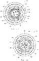
- a cross-sectional view of an example of a fiber optic coaxial electrical slickline 101is shown for use in coiled tubing applications. That is, with added reference to Fig. 2 , the slickline 101 may be pumped through coiled tubing 215 and used to provide a connection between a downhole tool 277, such as a perforating gun, and surface equipment 225.
- the features of the slickline 101are such that this connection may be used to provide power, distributed measurements, and telemetry, such as transmitting commands to and receiving information between the tool 277 and the surface equipment 225.
- the core 100 of the slicklineincludes fiber optic threads 109 for telemetry and/or measurements, such as distributed measurements, whereas electrical members 105 are provided for delivering power to the downhole tool 277.
- the electrical members 105may also be utilized for telemetry.
- the electrical members 105are coaxial conductors or threads.
- alternative member configurationsmay be utilized such as those of a half-shell configuration 106.
- the members 105, 106are of copper or other suitably conductive metal-based material given the environment in which the slickline 101 (or 102) is to be utilized.
- the members 105, 106may provide upwards of 100 Watts or more to downhole tools from the surface equipment 225. Thus, sufficient power may be made available to the perforating gun 277 for the application at hand.
- thismay include the ability to monitor and perform analysis with an associated logging tool 275, to transmit commands to trigger the perforating of the gun 277, or to transmit commands to actuate a valve or valves in the tool 275.
- the slickline 101, 102 of Figs. 1A and 1Bis configured to be run through coiled tubing 215 as noted above and depicted in Fig. 2 .
- minimizing the overall diameter of the slickline 101, 102may also be advantageous to allow for running through a coiled tubing 215 having its own diameter limitations.
- slickline 101, 102 embodiments hereinmay have an overall outer diameter of less than about 3.81mm (0.15 inches) even though a substantial portion of the slickline 101, 102 is occupied by conductive members 105, 106 capable of delivering power to the extent noted above.
- the coiled tubing 215defines an internal flow path 216 for delivery of treatment fluid or the like to a downhole tool such as, but not limited to, a treatment tool, or the like, discussed in more detail hereinbelow.
- these members 105, 106are intentionally left un-insulated relative the tube 107.
- the tube 107may take on charged conductive behavior as power is transferred over the members 105, 106. In turn, this may leave the underlying threads 109 exposed to a degree of charge.
- the mode of telemetry for the slickline 101, 102is to use jacketed threads 109 that are fiber optic in nature, no marked effect would be expected. That is, even in circumstances where the metallic tube 107 becomes charged by power carrying conductive members 105, 106, contact between the charged tube 107 and the threads 109 would not markedly affect the light-based fiber optic telemetry that is utilized through the threads 109.
- the coaxial conductive members 105may be helically wound about the underlying metal tube 107 sufficiently tight enough to avoid notable slippage between these components during manufacture and use of the slickline 101. Indeed, in the embodiment shown, the tube 107 is up to about 98% or more covered by the wound members 105. Further, an insulating polymer layer 125 may be extruded over the members 105 for providing electrical isolation from metal-based cladding layers 150, 175. However, the absence of a similar isolating layer between the members 105 and the metal tube 107 of the core 100 provides a practical manner of utilizing separate dedicated telemetric (109) and power (105) lines without adding substantially to the overall diameter of the slickline 101. Ultimately such a configuration may render a slickline 101 that may be about 10-20% smaller in diameter as compared to one in which the same components are utilized but with an insulating layer located between the members 105 and the metal tube 107.
- an added polymer jacketsuch as a foam polymer layer, or refractive tape may be utilized there-over (external to the polymer layer 125) to provide increased protection to the underlying fiber optic threads 109 from compression forces, heat and other processing hazards during manufacture of the slickline 101.
- Such materialsmay include reinforced carbon fiber, fluoropolymers or foamed polymers to absorb compression and prevent substantial optical losses.
- double cladded layers 150, 175are also utilized as noted above. These layers 150, 175 may provide durable shell for the slickline 101 and also be coupled to downhole electronics and/or application coiled tubing 215 so as to serve as conductive grounding members (see also Fig. 2 ). The thicknesses of these layers 150, 175 may depend upon diameter limitations for the slickline 101, as well as desired strength and flexibility. In the example shown a small gap is present between these layers 150, 175 where a supportive layer of polymer 177 is located to again protect underlying components from compression and/or heat during manufacture.
- This supportive layer 177 of polymermay again comprise reinforced carbon fiber, fluoropolymer, foamed polymer or other suitable supportive polymer type.
- a slickline 103similar to the slickline 101, may comprise a single cladded layer 176 in lieu of layers 150, 175 shown in Figs. 1a and 1b .
- the thickness of this single layer 176may depend upon diameter limitations for the slickline 101, 102, as well as desired strength and flexibility.
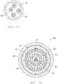
- a cross-sectional view slickline 102 for use in coiled tubing applicationsis shown which utilizes half-shell electrically conductive members 106 at its core 110 as noted above.
- the half-shell members 106may provide power and even telemetry where called for. Due to the shape of these members 106, the underlying metallic tube 107 may be completely encased and covered by the members 106 in a substantially conformal fashion and without the need for any intervening insulating layer therebetween as detailed above.
- an insulating layer 190may be provided exteriorly about these members 106 to provide electrical isolation from metal-based cladding layers 150, 170.
- the core 110may include multiple pairs of members 106, for example, each surrounding an individual fiber optic thread 109.
- advantagesmay be realized in terms of both space savings and user friendliness (e.g. in terms of manually terminating each member 106 at a downhole tool location).
- an added polymer jacket 180 or refractive tapemay be utilized there-over to provide increased protection to the underlying core 110 from compression forces, heat and other processing hazards during manufacture of the slickline 102.
- Such materialsmay comprise reinforced carbon fiber, fluoropolymers or foamed polymers to absorb compression and prevent substantial optical losses.
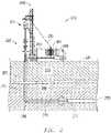
- coiled tubing 215is run through the well 280 to deliver a perforating gun 277 for sake of a perforating application.
- This coiled tubingincludes the noted gun 277 as well as a logging tool 275 and potentially other devices that may benefit from both telemetry, distributed measurements and/or power from surface equipment 225.
- the coiled tubing 215may be outfitted with an embodiment of slickline 101, 102 such as detailed above and depicted in Figs. 1A and 1B .
- a logging applicationmay take place as the coiled tubing 215 is run through a deviated section of the well 280.
- a slickline 101, 102may be disposed within an interior of the coiled tubing 215 that is communicatively coupled to the logging tool 275.
- characteristics of the well 280 over the various formation layers 290, 295may be detected by way of the tool 275.
- the fiber optic nature of the slickline 101, 102allows for certain detections or measurements, such as, but not limited to, temperature, pressure, strain and/or vibration readings, to be taken directly with fiber optic threads 109 apart from the noted tool 275.
- Such temperature, strain, pressure, and/or vibration readingsmay include distributed temperature sensing (DTS), distributed pressure sensing (DPS), distributed strain and temperature sensing (DSTS), distributed vibration sensing (DVS), heated DTS and others as discussed further below which utilize the fiber optic threads 109 and may be appreciated by those skilled in the art.
- DTSdistributed temperature sensing
- DPSdistributed pressure sensing
- DSTSdistributed strain and temperature sensing
- DTSdistributed vibration sensing
- heated DTSmay include distributed temperature sensing (DTS), distributed pressure sensing (DPS), distributed strain and temperature sensing (DSTS), distributed vibration sensing (DVS), heated DTS and others as discussed further below which utilize the fiber optic threads 109 and may be appreciated by those skilled in the art.
- the tool 275may be effectively powered without reliance on a downhole power source. That is, as noted above, the electrically conductive nature of the slickline 101, 102 allows power for the tool 275 to be obtained from surface equipment 225.
- telemetrymay be accomplished with the
- the surface equipment 225includes a power control unit 240 that may be coupled to the coiled tubing 215 by way of a reel 260.
- a power control unit 240may be coupled to the coiled tubing 215 by way of a reel 260.
- effective powering of the downhole tool 275may be surface directed as well as the overall coiled tubing application.
- data from the tool 275(or directly from slickline 101, 102 of Figs. 1A or 1B ) may be analyzed in real-time.
- a mobile coiled tubing truck 250is utilized for deployment of the slickline equipped coiled tubing 215 via a conventional gooseneck injector 255 with supportive rig 245.
- the coiled tubing 215may be forcibly injected past pressure control equipment 265 and through the tortuous well 280 for the logging application.
- the low profile, yet power capable slickline 101, 102 that is utilized through the coiled tubing 215allows for additional perforating and potentially other applications to be adequately directed and powered from surface (see Figs. 1A and 1B ).
- the wellbore device or tool 275may comprise a measurement device to measure a property and generate an output and an interface device to convert the output from the measurement device to an optical or electrical signal.
- the propertymay be any property that can be measured in a borehole such as, but not limited to, pressure, temperature, distributed temperature, pH, amount of precipitate, fluid temperature, depth, chemical luminescence, gamma-ray, resistivity, salinity, fluid flow, fluid compressibility, viscosity, compression, stress, strain, tool location, tool state, tool orientation, and combinations thereof.
- the tool 275may comprise a device to enter a predetermined branch of a multi-lateral well.
- the wellboremay be a multilateral well and the measured property be a tool orientation or a tool position.
- Types of wellbore devices and/or tools 275may comprise a camera, a caliper, a feeler, a casing collar locator, a sensor, a temperature sensor, a chemical sensor, a pressure sensor, a proximity sensor, a resistivity sensor, an electrical sensor, an actuator, an optically activated tool, a chemical analyzer, a flow-measuring device, a valve actuator, a firing head actuator, a tool actuator, a reversing valve, a check valve, and a fluid analyzer.
- the wellbore device or tool 275may be provided power and telemetry by the cable 101, 102, 301, 302, 500 or the like.
- a variety of wellbore and/or coiled tubing operations or applicationsmay be performed, such as matrix stimulation, fill cleanout, fracturing, scale removal, zonal isolation, perforation, downhole flow control, downhole completion manipulation, well logging, fishing, drilling, milling, measuring a physical property, locating a piece of equipment in the well, locating a particular feature in a wellbore, controlling a valve, and controlling a tool, as will be appreciated by those skilled in the art.
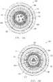
- FIG. 3Aa cross-sectional view of another example of fiber optic coaxial electrical slickline 301 is shown that may be utilized in coiled tubing applications such as that depicted in Fig. 2 .
- the core 300includes the fiber optic threads 109 disposed in a conduit 112 of a metallic tube 107 as with the examples of Figs 1A and 1B .
- electrically conductive members 105are again wound directly about the tube 107.
- a second layer of coaxial electrically conductive members 305are also wound about the exterior of the members 105.
- an added insulating polymer layer 125may be utilized on the exterior of the underlying conductive member layers 105, 305.
- isolation from outer cladding layers 150, 175may again be provided as well as additional processing and manufacturing protection. Indeed, the same holds true for the example of Fig. 3B discussed herebelow.
- a cross-sectional view of an example of a fiber optic combined coaxial and half-shell electrical slickline 302is shown that may be utilized in coiled tubing applications such as that depicted in Fig. 2 .
- the core 310includes both a pair of half-shell conductive members 106 as well as coaxial conductive members 105.
- the half-shell members 106may be used to define the conduit 312 through which the fiber optic threads 109 are run.
- a layer of insulating polymer 304may be present about the half-shell members 106 to provide isolation between relative the adjacent coaxial members 105.
- a layer of insulating polymersimilar to the layer 304, may be disposed between the conductive members 105 and metal tube 107 of Figs. 1a , 1c , 3a , or between the half-shell members 106 and metal tube 107 of Fig. 1b .
- Utilizing multiple modes of power delivery in this mannermay allow for more power to be delivered similar to the example of Fig. 3A .
- these modesmay be utilized differently from one another.
- the half-shell members 106may be utilized to power one downhole tool while the coaxial members 105 are utilized to power another downhole tool.
- one of the members 105, 106may be dedicated to power delivery, for example, whereas the other is used as a grounding return path.
- an insulating or polymer protective layermay also be present at the interior of the half-shell members 106 defining the conduit 312.
- the half-shell members 106may not be exposed directly to the conduit 312.
- a substantial isolating layeris not required for insulating the fiber optic threads 109 from potential charge of the half-shell members 106.
- the conduit 312may be filled with a hydrogen scavenging gel occupying the space around the fiber optic threads 109.
- the hydrogen scavenging gelmay prevent moisture from collecting in the conduit 312.
- the hydrogen scavenging gel(and other types of gels) may be effective, at non-extreme temperatures, to reduce the amount of hydrogen darkening that may affect the life of the fibers 109.
- such a gelmay be located in the conduits 112 of other embodiments as well, perhaps depending on the temperatures expected downhole for the given slickline 101, 102, 301 (see Figs. 1A, 1B and 3A ).
- a flow-chartis depicted which summarizes examples of utilizing fiber optic electrical slickline to run a coiled tubing interventional application in a well.
- a slicklinesuch as those depicted in Figs. 1A, 1B , 3A and 3B may be pumped through coiled tubing as indicated at 415.
- the coiled tubingmay be outfitted with a slickline that is equipped with fiber optic telemetry, distributed measurement capability, and power transferring capability while at the same time remaining of a profile adequately small enough to be utilized in the flow path 216 of the coiled tubing 215.
- the robustness of the fiber optic slickline 101, 102, 301, 302allows the slickline 101, 102, 301, 302, to provide telemetry and/or power at an extensive range of fluid flow rates through the fluid flow path 216 during wellbore operations (such as including flow rates up to those flow rates typically seen in hydraulic fracturing operations and the like, as will be appreciated by those skilled in the art) and fluid types (including viscous fluids such as gels and the like) while maintaining its structural integrity.
- the slickline 101, 102, 301, 302may be utilized with wellbore operations such as, but not limited to, a fluid pumping operation, a fracturing operation, an acidizing operation, a drilling operation, a coiled tubing operation, matrix stimulation, fill cleanout, fracturing, scale removal, zonal isolation, perforation, downhole flow control, downhole completion manipulation, well logging, fishing, drilling, milling, measuring a physical property, locating a piece of equipment in the well, locating a particular feature in a wellbore, controlling a valve, and controlling a tool, as will be appreciated by those skilled in the art.
- wellbore operationssuch as, but not limited to, a fluid pumping operation, a fracturing operation, an acidizing operation, a drilling operation, a coiled tubing operation, matrix stimulation, fill cleanout, fracturing, scale removal, zonal isolation, perforation, downhole flow control, downhole completion manipulation, well logging, fishing, drilling, milling, measuring
- the toolmay engage in telemetric communication with the surface equipment as indicated at 460 while also being powered to perform an application by the surface equipment as noted at 475.
- downhole toolssuch as logging and perforating tools may engage in telemetric communication with the surface equipment, before, during or even after a perforating application.
- This telemetric communicationmay take place over the fiber optics of the slickline of the coiled tubing.
- electrically conductive members of the slicklinemay be used to deliver power to these downhole tools to power these downhole tools and/or applications.
- Fig. 5Aa cross-sectional view of an example of the metallic tube 107 defining the conduit 112 for the fiber optic threads 109 is shown, alone.
- these threads 109provide the telemetric capacity as described herein.
- the threads 109may support distributed measurement of downhole distances, single or double ended distributed temperature sensing (DTS), distributed strain and temperature sensing (DSTS), distributed vibration sensing (hDVS), distributed fluid velocity sensing (DFVS), heated distributed fluid velocity sensing (HDFVS).
- DTSdistributed temperature sensing
- DSTSdistributed strain and temperature sensing
- hDVSdistributed vibration sensing
- DFVSdistributed fluid velocity sensing
- HDFVSheated distributed fluid velocity sensing
- the threads 109may be left loosely suspended as shown in part to ensure effective distributed sensing applications as indicated.
- FIG. 5Ba cross-sectional view of an example of a fiber optic electrical slickline 500 is shown that utilizes a tubeless core. That is, similar to the example of Fig. 3B , half-shell conductive members 106 may be utilized to define the conduit 112 through which the fiber optic threads 109 are run. However, in this example, the half-shell members 106 are entirely extruded with a continuous polymer layer 501 thereabout. Thus, the polymer layer 501 directly defines the conduit 112.
- the fibers 109may be bundled together so as to behave in a more cohesive manner, for example, as compared to the looser manner in which the fibers 109 are located in the conduit 112 of other examples such as that of Fig. 5A .
- this bundle or micro-bundle of fibers 109may even be held together by a single polymer jacket surrounding all of the fibers 109 simultaneously within the conduit 112.
- the slickline 500 of Fig. 5Bmay comprise double cladded layers 150, 175 to provide a durable shell which may also be coupled to downhole electronics and/or coiled tubing 215 (see also Fig. 2 ).
- the thicknesses of these layers 150, 175may depend upon diameter limitations for the slickline 101, as well as desired strength and flexibility.
- a small gapis present between these layers 150, 175 where a supportive layer of polymer (such as the polymer 177 shown in Fig. 1a ) is located to again protect underlying components from compression and/or heat during manufacture.
- This supportive layer of polymermay again be reinforced carbon fiber, fluoropolymer, foamed polymer or other suitable supportive polymer type.
- the slickline 501may comprise a single cladded layer to replace the layers 150, 175, similar to the embodiment shown in Fig. 1c .
- the thicknesses of this single layermay depend upon diameter limitations for the slickline 101, 102, as well as desired strength and flexibility.
- Examples detailed hereinaboveinclude slickline capable of providing telemetry and power to downhole tools while remaining of an adequately low profile to allow for practical use of the slickline in combination with coiled tubing applications. This may be achieved in a variety of manners.
Landscapes
- Engineering & Computer Science (AREA)
- Physics & Mathematics (AREA)
- Life Sciences & Earth Sciences (AREA)
- Geology (AREA)
- Mining & Mineral Resources (AREA)
- Remote Sensing (AREA)
- General Life Sciences & Earth Sciences (AREA)
- Geochemistry & Mineralogy (AREA)
- Environmental & Geological Engineering (AREA)
- Fluid Mechanics (AREA)
- Geophysics (AREA)
- Mechanical Engineering (AREA)
- General Physics & Mathematics (AREA)
- Optics & Photonics (AREA)
- Electromagnetism (AREA)
- Rigid Pipes And Flexible Pipes (AREA)
- Insulated Conductors (AREA)
- Investigating Or Analyzing Materials By The Use Of Electric Means (AREA)
- Cable Accessories (AREA)
Description
- Exploring, drilling and completing hydrocarbon and other wells are generally complicated, time consuming, and ultimately very expensive endeavors. In recognition of these expenses, added emphasis has been placed on efficiencies associated with well completions and maintenance over the life of the well. So, for example, enhancing efficiencies in terms of logging, perforating or any number of interventional applications may be of significant benefit, particularly as well depth and complexity continues to increase.
- One manner of enhancing efficiencies for interventional applications involves outfitting coiled tubing tools and equipment with power or telemetric capacity. Thus, applications requiring real-time communications or power may be run in, or upon traversing, tortuous or horizontal well sections. That is, coiled tubing may forcibly provide access to such well locations so that a logging tool or perforating gun may perform a logging or perforating application at or beyond such sections.
- In the case of a coiled tubing logging application, a telemetric line is disposed through the coiled tubing so as to provide communication between the logging tool and surface equipment at the oilfield. In this manner, operators may be provided with real-time position and well characteristic information. However, as opposed to a conventional wireline application, the telemetric line for the coiled tubing logging application is to be run through coiled tubing as noted. Thus, instead of utilizing a thick or larger diameter power-delivery line which might be more challenging to pump through the coiled tubing, a lighter, fiber-optic tether or "slickline" may be utilized to provide telemetry or communications between the logging tool and the surface equipment.
- While adept at providing the benefits of a low-profile and lightweight means of data transmission, the fiber optic slickline remains devoid of any electrically conductive capacity. That is, in contrast to the above noted wireline cable, the fiber optic slickline is devoid of the heavier electrical cabling. While this is advantageous for reasons noted hereinabove, it means that reliance on a dedicated, space consuming, downhole power source is still required. Thus, the power available to monitoring equipment is limited to the constraints of such a power source. Once more, as noted above, application tools of greater power requirements than a logging tool may be utilized at the end of the coiled tubing such as where a perforating gun is provided for sake of a perforating application.
- In addition to the challenges directly related to the lack of dedicated power, a fiber optic tether or slickline is of a naturally lower strength to weight ratio thereby limiting overall depth capabilities. Once more, the problems associated with power limitations and current construction of fiber optic slickline do not lend to merely adding in an electrical line. For example, inserting a separate electrical line into the metal tube might address the lack of surface available power. However, a dedicated power line would tend to increase the overall diameter of the slickline. Indeed, when considering conventional insulating and other layers of the added electrical line, the slickline may begin to take on dimensions and weight more characteristic of wireline. Thus, the advantage of utilizing slickline may begin to be lost.
- At present, in the case of coiled tubing applications that utilize telemetry, distributed measurements, and powered application tools, operators are generally left with the only practical option of a fiber optic slickline lacking electrically conductive capacity. As a result, a dedicated downhole power source is provided for the tool which is of limited total power capacity and having the undesirable characteristic of eating up space on the tool assembly.
WO2012/071101 describes a fiber optic cable including: a first elongated body having a longitudinal axis, an elongated sleeve disposed coaxially with the first elongated body, the elongated sleeve including a plurality of second elongated bodies wrapped around an exterior surface of the first elongated body and at least one elongated fiber optic components disposed inside of and coaxially with at least one of the first elongated body and a second elongated body.US 5495547 describes a well logging cable including first conductor elements, each consisting of a steel wire surrounded by copper strands and covered in an electrically insulating material, and at least one second conductor element including at least one optical fiber enclosed in a metal tube, copper strands surrounding the tube and the strands covered by the electrically insulating material. The first elements and the at least one second element are arranged in a central bundle. The second conductor element is positioned within the bundle so as to be helically wound around a central axis of the bundle. The bundle is surrounded by armor wires helically wound externally to the bundle. Further prior art with regard to the topic of the invention can be found inUS20143671219 .- The present invention resides in an electrically conductive fiber optic slickline as defined in
claims 1 to 7, a coiled tubing assembly for use in an application at a location in a well at an oilfield with surface equipment positioned thereat as defined in claims 8-9, and in a method of performing a coiled tubing application at a location in a well at an oilfield as defined in claims 10 and 11. Fig. 1A is a cross-sectional view of an embodiment of a fiber optic coaxial electrical slickline for use in coiled tubing applications.Fig. 1B is a cross-sectional view of an embodiment of a fiber optic half-shell electrical slickline for use in coiled tubing applications.Fig. 2 is an overview of an oilfield with a well accommodating the coiled tubing for an application that utilizes an embodiment of slickline as shown in one ofFigs. 1A and 1B .Fig. 3A is a cross-sectional view of another embodiment of fiber optic coaxial electrical slickline for use in coiled tubing applications.Fig. 3B is a cross-sectional view of an embodiment of a fiber optic combined coaxial and half-shell electrical slickline for use in coiled tubing applications.Fig. 4 is a flow-chart summarizing embodiments of utilizing fiber optic electrical slickline to run a coiled tubing interventional application in a well.Fig. 5A is a cross-sectional view of an embodiment of a fiber optic metal tubular core of a fiber optic electrical slickline.Fig. 5B is a cross-sectional view of an embodiment of a fiber optic electrical slickline utilizing a tubeless core.- Embodiments are described with reference to certain tools and coiled tubing applications run in a well over slickline. As defined herein, the term "slickline" refers to an application that is run over a conveyance line that is substantially below about 6.35 mm (0.25 inches) in overall outer diameter. That is, as opposed to a higher profile or diameter wireline cable, downhole applications detailed herein are run over a relatively low diameter slickline. Additionally, the embodiments detailed herein are described with reference to particular perforating applications and tools that are advanced through the well with the aid of coiled tubing. These embodiments employ a fiber optic electrical core that includes fiber optic thread with an electrically conductive member disposed about the core to render a practical and effective electrically conductive fiber optic slickline.
- Referring specifically now to
Fig. 1A , a cross-sectional view of an example of a fiber optic coaxialelectrical slickline 101 is shown for use in coiled tubing applications. That is, with added reference toFig. 2 , theslickline 101 may be pumped through coiledtubing 215 and used to provide a connection between adownhole tool 277, such as a perforating gun, andsurface equipment 225. The features of theslickline 101 are such that this connection may be used to provide power, distributed measurements, and telemetry, such as transmitting commands to and receiving information between thetool 277 and thesurface equipment 225. More specifically, thecore 100 of the slickline includes fiberoptic threads 109 for telemetry and/or measurements, such as distributed measurements, whereaselectrical members 105 are provided for delivering power to thedownhole tool 277. However, in certain embodiments, theelectrical members 105 may also be utilized for telemetry. - In the example of
Fig. 1A , theelectrical members 105 are coaxial conductors or threads. However, with added reference toFig. 1B , alternative member configurations may be utilized such as those of a half-shell configuration 106. Regardless, themembers slickline coiled tubing 215 ofFig. 2 are upwards of 35,000 feet in length, themembers surface equipment 225. Thus, sufficient power may be made available to the perforatinggun 277 for the application at hand. In the case of a perforating application as depicted, this may include the ability to monitor and perform analysis with an associatedlogging tool 275, to transmit commands to trigger the perforating of thegun 277, or to transmit commands to actuate a valve or valves in thetool 275. - In contrast to more conventional powered cables, such as wireline cable, the
slickline Figs. 1A and 1B is configured to be run through coiledtubing 215 as noted above and depicted inFig. 2 . Thus, while power delivery may be sought as noted above, minimizing the overall diameter of theslickline coiled tubing 215 having its own diameter limitations. For example,slickline slickline conductive members conductive members coiled tubing 215 defines aninternal flow path 216 for delivery of treatment fluid or the like to a downhole tool such as, but not limited to, a treatment tool, or the like, discussed in more detail hereinbelow. - Continuing with reference to
Figs. 1A and 1B , the fiberoptic threads 109 may be loosely run through ametallic tube 107. A conventional polymer jacket may be present about eachindividual thread 109. However, as noted, theconduit 112 defined by thetube 107 may be left void of any filler material so as to allow a degree of flexibility and independence between thethreads 109 and the remainder of theslickline slickline threads 109. However, this also means that thethreads 109 are subject to a degree of movement within theconduit 112 including regular contact with the inner wall of themetallic tube 107. As shown in the embodiments ofFigs. 1A and 1B ,conductive members metallic tube 107. - As opposed to the conventional manner of insulating the
members metallic tube 107, thesemembers tube 107. As a result, even thetube 107 may take on charged conductive behavior as power is transferred over themembers underlying threads 109 exposed to a degree of charge. However, given that the mode of telemetry for theslickline threads 109 that are fiber optic in nature, no marked effect would be expected. That is, even in circumstances where themetallic tube 107 becomes charged by power carryingconductive members tube 107 and thethreads 109 would not markedly affect the light-based fiber optic telemetry that is utilized through thethreads 109. - With specific reference to
Fig. 1A , the coaxialconductive members 105 may be helically wound about theunderlying metal tube 107 sufficiently tight enough to avoid notable slippage between these components during manufacture and use of theslickline 101. Indeed, in the embodiment shown, thetube 107 is up to about 98% or more covered by thewound members 105. Further, an insulatingpolymer layer 125 may be extruded over themembers 105 for providing electrical isolation from metal-based cladding layers 150, 175. However, the absence of a similar isolating layer between themembers 105 and themetal tube 107 of thecore 100 provides a practical manner of utilizing separate dedicated telemetric (109) and power (105) lines without adding substantially to the overall diameter of theslickline 101. Ultimately such a configuration may render aslickline 101 that may be about 10-20% smaller in diameter as compared to one in which the same components are utilized but with an insulating layer located between themembers 105 and themetal tube 107. - In addition to the insulating
polymer layer 125, an added polymer jacket, such as a foam polymer layer, or refractive tape may be utilized there-over (external to the polymer layer 125) to provide increased protection to the underlying fiberoptic threads 109 from compression forces, heat and other processing hazards during manufacture of theslickline 101. Such materials may include reinforced carbon fiber, fluoropolymers or foamed polymers to absorb compression and prevent substantial optical losses. - Continuing with reference to
Fig. 1A , double claddedlayers layers slickline 101 and also be coupled to downhole electronics and/or application coiledtubing 215 so as to serve as conductive grounding members (see alsoFig. 2 ). The thicknesses of theselayers slickline 101, as well as desired strength and flexibility. In the example shown a small gap is present between theselayers polymer 177 is located to again protect underlying components from compression and/or heat during manufacture. Thissupportive layer 177 of polymer may again comprise reinforced carbon fiber, fluoropolymer, foamed polymer or other suitable supportive polymer type. In an embodiment of the invention, best seen inFig. 1c , aslickline 103, similar to theslickline 101, may comprise a single claddedlayer 176 in lieu oflayers Figs. 1a and 1b . The thickness of thissingle layer 176 may depend upon diameter limitations for theslickline - With particular reference to the embodiment depicted in
Fig. 1B , across-sectional view slickline 102 for use in coiled tubing applications is shown which utilizes half-shell electricallyconductive members 106 at itscore 110 as noted above. As with thecoaxial members 105 ofFig. 1A , the half-shell members 106 may provide power and even telemetry where called for. Due to the shape of thesemembers 106, the underlyingmetallic tube 107 may be completely encased and covered by themembers 106 in a substantially conformal fashion and without the need for any intervening insulating layer therebetween as detailed above. However, an insulatinglayer 190 may be provided exteriorly about thesemembers 106 to provide electrical isolation from metal-based cladding layers 150, 170. - Again though, in the example of
Fig. 1B , there remains an absence of an isolating layer between themembers 106 and themetal tube 107 of thecore 110. This provides a practical manner of utilizing separate dedicated telemetric (109) and power (106) lines without adding substantially to the overall diameter of theslickline 102. As with the example ofFig. 1A , such a configuration may render aslickline 102 that is about 10-20% smaller in diameter as compared to one in which the same components are utilized but with an insulating layer located between themembers 106 and themetal tube 107. Once more, in the example ofFig. 1B , a single pair of half-shell members 106 is utilized. However, in other examples, thecore 110 may include multiple pairs ofmembers 106, for example, each surrounding an individualfiber optic thread 109. Nevertheless, in the example shown, where a single pair of half-shell members 106 is utilized, advantages may be realized in terms of both space savings and user friendliness (e.g. in terms of manually terminating eachmember 106 at a downhole tool location). - Continuing with reference to
Fig. 1B , in addition to the insulatingpolymer layer 190, an addedpolymer jacket 180 or refractive tape may be utilized there-over to provide increased protection to theunderlying core 110 from compression forces, heat and other processing hazards during manufacture of theslickline 102. Such materials may comprise reinforced carbon fiber, fluoropolymers or foamed polymers to absorb compression and prevent substantial optical losses. - Referring now to
Fig. 2 , an overview of anoilfield 201 is shown with a well 280 traversing various formation layers 290, 295. As depicted,coiled tubing 215 is run through the well 280 to deliver a perforatinggun 277 for sake of a perforating application. This coiled tubing includes the notedgun 277 as well as alogging tool 275 and potentially other devices that may benefit from both telemetry, distributed measurements and/or power fromsurface equipment 225. Thus, thecoiled tubing 215 may be outfitted with an embodiment ofslickline Figs. 1A and 1B . - As shown in
Fig. 2 , a logging application may take place as thecoiled tubing 215 is run through a deviated section of thewell 280. With added reference toFigs. 1A and 1B , aslickline tubing 215 that is communicatively coupled to thelogging tool 275. Thus, characteristics of the well 280 over the various formation layers 290, 295 may be detected by way of thetool 275. Once more, the fiber optic nature of theslickline optic threads 109 apart from thenoted tool 275. Such temperature, strain, pressure, and/or vibration readings may include distributed temperature sensing (DTS), distributed pressure sensing (DPS), distributed strain and temperature sensing (DSTS), distributed vibration sensing (DVS), heated DTS and others as discussed further below which utilize the fiberoptic threads 109 and may be appreciated by those skilled in the art. Additionally, to the extent necessary, thetool 275 may be effectively powered without reliance on a downhole power source. That is, as noted above, the electrically conductive nature of theslickline tool 275 to be obtained fromsurface equipment 225. In an embodiment, telemetry may be accomplished with theconductive members 105 instead of theoptical fibers 109, such as in the event of a failure of one or more of theoptical fibers 109. - In the example shown, the
surface equipment 225 includes apower control unit 240 that may be coupled to the coiledtubing 215 by way of areel 260. Thus, as indicated, effective powering of thedownhole tool 275 may be surface directed as well as the overall coiled tubing application. Additionally, data from the tool 275 (or directly fromslickline Figs. 1A or 1B ) may be analyzed in real-time. - In this example, a mobile
coiled tubing truck 250 is utilized for deployment of the slickline equipped coiledtubing 215 via aconventional gooseneck injector 255 withsupportive rig 245. Thus, thecoiled tubing 215 may be forcibly injected pastpressure control equipment 265 and through the tortuous well 280 for the logging application. Once more, the low profile, yet powercapable slickline tubing 215 allows for additional perforating and potentially other applications to be adequately directed and powered from surface (seeFigs. 1A and 1B ). In an example the wellbore device ortool 275 may comprise a measurement device to measure a property and generate an output and an interface device to convert the output from the measurement device to an optical or electrical signal. The property may be any property that can be measured in a borehole such as, but not limited to, pressure, temperature, distributed temperature, pH, amount of precipitate, fluid temperature, depth, chemical luminescence, gamma-ray, resistivity, salinity, fluid flow, fluid compressibility, viscosity, compression, stress, strain, tool location, tool state, tool orientation, and combinations thereof. In some examples, thetool 275 may comprise a device to enter a predetermined branch of a multi-lateral well. The wellbore may be a multilateral well and the measured property be a tool orientation or a tool position. Types of wellbore devices and/ortools 275 may comprise a camera, a caliper, a feeler, a casing collar locator, a sensor, a temperature sensor, a chemical sensor, a pressure sensor, a proximity sensor, a resistivity sensor, an electrical sensor, an actuator, an optically activated tool, a chemical analyzer, a flow-measuring device, a valve actuator, a firing head actuator, a tool actuator, a reversing valve, a check valve, and a fluid analyzer. The wellbore device ortool 275 may be provided power and telemetry by thecable - Referring now to
Fig. 3A , a cross-sectional view of another example of fiber optic coaxialelectrical slickline 301 is shown that may be utilized in coiled tubing applications such as that depicted inFig. 2 . In this example, thecore 300 includes the fiberoptic threads 109 disposed in aconduit 112 of ametallic tube 107 as with the examples ofFigs 1A and 1B . Similarly, electricallyconductive members 105 are again wound directly about thetube 107. However, in the example ofFig. 3A , a second layer of coaxial electricallyconductive members 305 are also wound about the exterior of themembers 105. Thus, the space that is saved in eliminating an insulating layer between theinitial members 105 and themetallic tube 107 as detailed above, is now, to a certain degree, exchanged for the introduction of an added layer ofmembers 305. In total, this may translate into as much as about a 20% or more increase in the power delivery capability of theslickline - As with the examples of
Figs. 1A and 1B , an added insulatingpolymer layer 125 may be utilized on the exterior of the underlying conductive member layers 105, 305. Thus, isolation from outer cladding layers 150, 175 may again be provided as well as additional processing and manufacturing protection. Indeed, the same holds true for the example ofFig. 3B discussed herebelow. - Referring specifically now to
Fig. 3B , a cross-sectional view of an example of a fiber optic combined coaxial and half-shellelectrical slickline 302 is shown that may be utilized in coiled tubing applications such as that depicted inFig. 2 . As alluded to, in this example, for power delivery, thecore 310 includes both a pair of half-shellconductive members 106 as well as coaxialconductive members 105. However, in this example, the half-shell members 106 may be used to define theconduit 312 through which the fiberoptic threads 109 are run. A layer of insulatingpolymer 304 may be present about the half-shell members 106 to provide isolation between relative the adjacentcoaxial members 105. In an example, a layer of insulating polymer, similar to thelayer 304, may be disposed between theconductive members 105 andmetal tube 107 ofFigs. 1a ,1c ,3a , or between the half-shell members 106 andmetal tube 107 ofFig. 1b . - Utilizing multiple modes of power delivery in this manner may allow for more power to be delivered similar to the example of
Fig. 3A . Alternatively, however, since these modes (105 and 106) are isolated from one another, they may be utilized differently from one another. For example, in an example, the half-shell members 106 may be utilized to power one downhole tool while thecoaxial members 105 are utilized to power another downhole tool. In an example, one of themembers - In an example, an insulating or polymer protective layer may also be present at the interior of the half-
shell members 106 defining theconduit 312. Thus, the half-shell members 106 may not be exposed directly to theconduit 312. However, it is worth noting that in the example ofFig. 3B , a substantial isolating layer is not required for insulating the fiberoptic threads 109 from potential charge of the half-shell members 106. - In the example shown, the
conduit 312 may be filled with a hydrogen scavenging gel occupying the space around the fiberoptic threads 109. The hydrogen scavenging gel may prevent moisture from collecting in theconduit 312. The hydrogen scavenging gel (and other types of gels) may be effective, at non-extreme temperatures, to reduce the amount of hydrogen darkening that may affect the life of thefibers 109. Of course, such a gel may be located in theconduits 112 of other embodiments as well, perhaps depending on the temperatures expected downhole for the givenslickline Figs. 1A, 1B and3A ). - Referring now to
Fig. 4 , a flow-chart is depicted which summarizes examples of utilizing fiber optic electrical slickline to run a coiled tubing interventional application in a well. For example, a slickline such as those depicted inFigs. 1A, 1B ,3A and 3B may be pumped through coiled tubing as indicated at 415. In this manner the coiled tubing may be outfitted with a slickline that is equipped with fiber optic telemetry, distributed measurement capability, and power transferring capability while at the same time remaining of a profile adequately small enough to be utilized in theflow path 216 of the coiledtubing 215. Thus, as indicated at 430, the slickline may be coupled at one end to surface equipment at an oilfield and at the other end to one or more downhole tools that are deployable via the coiled tubing. Accordingly, the coiled tubing may be used to advance downhole tools to a particular location in the well (see 445). The robustness of thefiber optic slickline slickline fluid flow path 216 during wellbore operations (such as including flow rates up to those flow rates typically seen in hydraulic fracturing operations and the like, as will be appreciated by those skilled in the art) and fluid types (including viscous fluids such as gels and the like) while maintaining its structural integrity. Theslickline - Ultimately, this means that the tool may engage in telemetric communication with the surface equipment as indicated at 460 while also being powered to perform an application by the surface equipment as noted at 475. By way of specific example, downhole tools such as logging and perforating tools may engage in telemetric communication with the surface equipment, before, during or even after a perforating application. This telemetric communication may take place over the fiber optics of the slickline of the coiled tubing. At the same time, electrically conductive members of the slickline may be used to deliver power to these downhole tools to power these downhole tools and/or applications.
- Referring now to
Fig. 5A , a cross-sectional view of an example of themetallic tube 107 defining theconduit 112 for the fiberoptic threads 109 is shown, alone. Thus, a brief revisiting of embodiments such as those ofFigs. 1A or3A , with focus on the fiberoptic threads 109, is rendered. Thesethreads 109 provide the telemetric capacity as described herein. Additionally, however, thethreads 109 may support distributed measurement of downhole distances, single or double ended distributed temperature sensing (DTS), distributed strain and temperature sensing (DSTS), distributed vibration sensing (hDVS), distributed fluid velocity sensing (DFVS), heated distributed fluid velocity sensing (HDFVS). Indeed, thethreads 109 may be left loosely suspended as shown in part to ensure effective distributed sensing applications as indicated. - Referring now to
Fig. 5B , a cross-sectional view of an example of a fiber opticelectrical slickline 500 is shown that utilizes a tubeless core. That is, similar to the example ofFig. 3B , half-shellconductive members 106 may be utilized to define theconduit 112 through which the fiberoptic threads 109 are run. However, in this example, the half-shell members 106 are entirely extruded with acontinuous polymer layer 501 thereabout. Thus, thepolymer layer 501 directly defines theconduit 112. - Additionally, the
fibers 109 may be bundled together so as to behave in a more cohesive manner, for example, as compared to the looser manner in which thefibers 109 are located in theconduit 112 of other examples such as that ofFig. 5A . In an example, this bundle or micro-bundle offibers 109 may even be held together by a single polymer jacket surrounding all of thefibers 109 simultaneously within theconduit 112. - As with other examples, the
slickline 500 ofFig. 5B may comprise double claddedlayers Fig. 2 ). The thicknesses of theselayers slickline 101, as well as desired strength and flexibility. In the example shown, a small gap is present between theselayers polymer 177 shown inFig. 1a ) is located to again protect underlying components from compression and/or heat during manufacture. This supportive layer of polymer may again be reinforced carbon fiber, fluoropolymer, foamed polymer or other suitable supportive polymer type. In an example, theslickline 501 may comprise a single cladded layer to replace thelayers Fig. 1c . The thicknesses of this single layer may depend upon diameter limitations for theslickline - Examples detailed hereinabove include slickline capable of providing telemetry and power to downhole tools while remaining of an adequately low profile to allow for practical use of the slickline in combination with coiled tubing applications. This may be achieved in a variety of manners.
Claims (11)
- An electrically conductive fiber optic slickline (101) adapted to be disposed within a flow path of coiled tubing (215), the coil tubing (215) accommodating a downhole tool (275) for an application in a well at an oilfield, the slickline (101) comprising:a polymer jacketed fiber optic thread (109) disposed through a void space defined by a conduit (112) of the slickline (101) to support telemetry between surface equipment (225) at the oilfield and the tool (275);an electrically conductive member (105, 106) to support powering of the downhole tool (275) from the surface equipment (225), the member (105, 106) located exteriorly adjacent the conduit (112) in an un-insulated manner relative thereto;an insulating polymer layer (125) over the electrically conductive member; and
characterized by a single metal based cladding layer (176) disposed circumferentially about the insulating polymer layer (125), wherein the overall diameter of the slickline (101) is less than 3.81 mm (0.15 inches). - The electrically conductive fiber optic slickline of claim 1, wherein the electrically conductive member (105, 106) is configured to provide telemetry between the surface equipment (225) and the tool (275).
- The electrically conductive fiber optic slickline of claim 1, wherein the polymer jacketed fiber optic thread (190) is configured to directly take a distributed measurement and transmit the measurement to the surface equipment (225), the measurement selected from a category consisting of temperature sensing, pressure sensing, vibration sensing, strain sensing, and fluid velocity sensing.
- The electrically conductive fiber optic slickline of claim 1, wherein the electrically conductive member comprises a plurality of: one of helically wound coaxial conductors (105) and half shell configurations of electrically conductive members (106) provided circumferentially about the conduit (112) accommodating the polymer jacketed fiber optic thread (109) and further comprising a metallic tube (107) defining the conduit (112) and accommodating the electrically conductive members (105, 106) thereover.
- The electrically conductive fiber optic slickline of claim 4, wherein the electrically conductive member comprises a plurality of half-shell electrically conductive members (106) jacketed by a polymer (180) to shield from exposure to the conduit (112).
- The electrically conductive fiber optic slickline of claim 4, wherein the electrically conductive members are a first layer of electrically conductive members (106) about the conduit (112), the slickline further comprising:an insulating polymer (304) about the first layer of members (106); anda second layer of electrically conductive members (105) about the insulating polymer (304).
- The electrically conductive fiber optic slickline of claim 6, wherein the second layer of electrically conductive members (105) is configured to serve one of power to another tool (275) accommodated by the coiled tubing (212) and as a grounding return.
- A coiled tubing assembly for use in an application at a location in a well at an oilfield with surface equipment (225) positioned thereat, the assembly comprising:coiled tubing (215);an electrically conductive fiber optic slickline (101) run through the flow path of the coiled tubing (215), the electrically conductive fiber optic slickline (101) as defined ir any preceding claim; and
a downhole tool (275) coupled to the coiled tubing (215) for advancement to the location in the well, the tool (275) telemetrically coupling to the fiber optic thread (190) of the slickline (101), the telemetric coupling for communications with the surface equipment (225) and electrically coupling to the conductive member (105, 106) of the slickline (101), the electrical coupling to obtain power from the surface equipment (225) for the application. - The coiled tubing assembly of claim 8, wherein the downhole tool (275) is a logging tool.
- A method of performing a coiled tubing application at a location in a well at an oilfield, the method comprising:pumping (415) a fiber optic slickline (101) through a flow path of a coiled tubing (215), the fiber optic slickline (101) as defined in any of claims 1 to 7;physically coupling a downhole tool (275) to the coiled tubing (215); communicatively coupling the fiber optic thread (190) of the fiber optic slickline (101) to the tool (275) to support communications between the tool (275) and surface equipment (225) at the oilfield;powerably coupling the electrically conductive member (105, 106) of the fiber optic slickline (101) to the tool (275) to provide power thereto;advancing (445) the tool (275) to the location with the coiled tubing (215);performing (460, 475) the application at the location, and utilizing the surface equipment (225) to transmit commands to and receive information from the tool (275) .
- The method of claim 10, further comprising utilizing the surface equipment (225) to obtain data detected directly by the fiber optic thread (190).
Applications Claiming Priority (1)
| Application Number | Priority Date | Filing Date | Title |
|---|---|---|---|
| PCT/US2015/012918WO2016122446A1 (en) | 2015-01-26 | 2015-01-26 | Electrically conductive fiber optic slickline for coiled tubing operations |
Publications (3)
| Publication Number | Publication Date |
|---|---|
| EP3250785A1 EP3250785A1 (en) | 2017-12-06 |
| EP3250785A4 EP3250785A4 (en) | 2018-09-12 |
| EP3250785B1true EP3250785B1 (en) | 2022-09-21 |
Family
ID=56543878
Family Applications (1)
| Application Number | Title | Priority Date | Filing Date |
|---|---|---|---|
| EP15880350.2AActiveEP3250785B1 (en) | 2015-01-26 | 2015-01-26 | Electrically conductive fiber optic slickline for coiled tubing operations |
Country Status (5)
| Country | Link |
|---|---|
| US (1) | US11725468B2 (en) |
| EP (1) | EP3250785B1 (en) |
| AR (1) | AR103527A1 (en) |
| SA (1) | SA517381986B1 (en) |
| WO (1) | WO2016122446A1 (en) |
Families Citing this family (12)
| Publication number | Priority date | Publication date | Assignee | Title |
|---|---|---|---|---|
| US12163394B2 (en) | 2009-04-17 | 2024-12-10 | Schlumberger Technology Corporation | Reduced torque wireline cable |
| US10087717B2 (en) | 2011-10-17 | 2018-10-02 | Schlumberger Technology Corporation | Dual use cable with fiber optics for use in wellbore operations |
| GB2518774B (en) | 2012-06-28 | 2020-01-29 | Schlumberger Holdings | High power opto-electrical cable with multiple power and telemetry paths |
| US10049789B2 (en) | 2016-06-09 | 2018-08-14 | Schlumberger Technology Corporation | Compression and stretch resistant components and cables for oilfield applications |
| GB201707957D0 (en)* | 2017-05-18 | 2017-07-05 | Paradigm Tech Services B V | System and method for use in measuring a property of an enviroment in, or adjacent to, and elongated space |
| US10598006B2 (en)* | 2017-05-30 | 2020-03-24 | Baker Hughes Oilfield Operations, Llc | Methods and systems for downhole sensing and communications in wells |
| CN109655982B (en)* | 2019-01-30 | 2024-06-07 | 南京嘉兆技术有限公司 | Armored strain monitoring optical cable, earthing monitoring and stress calibration method |
| CN114026658A (en)* | 2019-06-28 | 2022-02-08 | 斯伦贝谢技术有限公司 | Mechanically Responsive Optical Fiber Wire Assemblies |
| GB2599553B (en) | 2019-06-28 | 2025-03-26 | Schlumberger Technology Bv | Stranded fiber-optic cable |
| GB202102527D0 (en)* | 2021-02-23 | 2021-04-07 | Wires&Bytes Gmbh | Downhole cable |
| WO2022261390A1 (en) | 2021-06-10 | 2022-12-15 | Schlumberger Technology Corporation | Electro-optical wireline cables |
| US20240254864A1 (en)* | 2023-01-31 | 2024-08-01 | Jacinto Delgado | Wireless perforating gun |
Citations (1)
| Publication number | Priority date | Publication date | Assignee | Title |
|---|---|---|---|---|
| US20140367121A1 (en)* | 2011-10-17 | 2014-12-18 | Schlumberger Technology Corporation | Dual Use Cable With Fiber Optic Packaging For Use In Wellbore Operations |
Family Cites Families (192)
| Publication number | Priority date | Publication date | Assignee | Title |
|---|---|---|---|---|
| US1937054A (en) | 1928-06-27 | 1933-11-28 | Cremer Carl | Oil-filled cable |
| US1921606A (en) | 1928-11-01 | 1933-08-08 | Cremer Carl | Multicore high tension cable |
| US1987041A (en) | 1932-07-30 | 1935-01-08 | Eastman Kodak Co | Camera view finder |
| US2261742A (en) | 1939-02-24 | 1941-11-04 | Cons Edison Co New York Inc | Electric cable |
| US2604509A (en) | 1948-04-06 | 1952-07-22 | Schlumberger Well Surv Corp | Nonspinning armored electric cable |
| US2927954A (en) | 1956-09-27 | 1960-03-08 | United States Steel Corp | Shielded oil well cable |
| US3217083A (en) | 1960-08-01 | 1965-11-09 | Gore & Ass | Abrasion resistant polymeric fluorocarbons and conductor insulated therewith |
| US3115542A (en) | 1961-05-02 | 1963-12-24 | Pirelli | Submarine electric cables |
| US3784732A (en) | 1969-03-21 | 1974-01-08 | Schlumberger Technology Corp | Method for pre-stressing armored well logging cable |
| US3602632A (en) | 1970-01-05 | 1971-08-31 | United States Steel Corp | Shielded electric cable |
| US3639674A (en) | 1970-06-25 | 1972-02-01 | Belden Corp | Shielded cable |
| SE403409B (en) | 1976-08-24 | 1978-08-14 | Ericsson Telefon Ab L M | SELF-FLOATING CABLE WITH GREAT FLEXIBILITY PREFERABLY FOR MARINE OPERATIONS |
| GB1595455A (en) | 1977-05-31 | 1981-08-12 | Standard Telephones Cables Ltd | Submarine optical fibre cables |
| US4131758A (en) | 1977-08-10 | 1978-12-26 | United States Steel Corporation | Double caged armored electromechanical cable |
| US4131757A (en) | 1977-08-10 | 1978-12-26 | United States Steel Corporation | Helically wound retaining member for a double caged armored electromechanical cable |
| US4183621A (en) | 1977-12-29 | 1980-01-15 | International Telephone And Telegraph Corporation | Water resistant high strength fibers |
| FR2422969A1 (en) | 1978-03-31 | 1979-11-09 | Kokusai Denshin Denwa Co Ltd | FIBER OPTIC UNDERWATER CABLE |
| DE2818656A1 (en) | 1978-04-27 | 1979-10-31 | Siemens Ag | Wideband cable network communication system - consists of insulated light conductors twisted with another light conductor and with two insulated metal wires |
| FR2444282A1 (en) | 1978-12-12 | 1980-07-11 | Cables De Lyon Geoffroy Delore | UNDERWATER CABLE WITH OPTICAL FIBERS FOR TELECOMMUNICATIONS, AND METHOD AND DEVICE FOR THE PRODUCTION THEREOF |
| FR2470392B1 (en) | 1979-11-22 | 1986-02-28 | Noane Georges Le | OPTICAL FIBER CABLES, PARTICULARLY FOR SUBSEA TRANSMISSION SYSTEMS |
| JPS5744107A (en) | 1980-08-29 | 1982-03-12 | Nippon Telegr & Teleph Corp <Ntt> | Optical fiber cable and its manufacture |
| US4389645A (en) | 1980-09-08 | 1983-06-21 | Schlumberger Technology Corporation | Well logging fiber optic communication system |
| US4375313A (en) | 1980-09-22 | 1983-03-01 | Schlumberger Technology Corporation | Fiber optic cable and core |
| FR2500638A1 (en) | 1981-02-20 | 1982-08-27 | Laurette Michel | OPTICAL FIBER CABLE |
| US4524436A (en) | 1981-05-15 | 1985-06-18 | Schlumberger Technology Corporation | Pressure wave fiber optic transducer cable |
| FR2508227A1 (en) | 1981-06-18 | 1982-12-24 | Cables De Lyon Geoffroy Delore | ELECTROMECHANICAL CABLE RESISTANT TO HIGH TEMPERATURES AND PRESSURES AND METHOD OF MANUFACTURING THE SAME |
| FR2530346B1 (en) | 1982-07-13 | 1986-05-16 | Schlumberger Prospection | METHOD AND DEVICE FOR ACQUIRING SEISMIC SIGNALS IN A WELL |
| FR2530345B1 (en) | 1982-07-13 | 1985-06-21 | Schlumberger Prospection | METHOD FOR COUPLING A SEISMIC DETECTOR TO THE WALL OF A WELL, AND SEISMIC ACQUISITION SENSOR FOR CARRYING OUT SAID METHOD |
| US4577925A (en) | 1982-08-13 | 1986-03-25 | Olin Corporation | Optical fiber communication cables and method and apparatus for assembling same |
| US4522464A (en) | 1982-08-17 | 1985-06-11 | Chevron Research Company | Armored cable containing a hermetically sealed tube incorporating an optical fiber |
| US4504112A (en) | 1982-08-17 | 1985-03-12 | Chevron Research Company | Hermetically sealed optical fiber |
| US4696542A (en) | 1982-08-17 | 1987-09-29 | Chevron Research Company | Armored optical fiber cable |
| US4523804A (en) | 1982-08-17 | 1985-06-18 | Chevron Research Company | Armored optical fiber cable |
| US4705353A (en) | 1983-03-28 | 1987-11-10 | Schlumberger Technology Corporation | Optical fiber cable construction |
| US4878733A (en) | 1983-05-24 | 1989-11-07 | Olin Corporation | Optical fiber communication cable having a high strength, drawn copper alloy tube |
| US4579420A (en) | 1983-06-16 | 1986-04-01 | Olin Corporation | Two-pole powered ruggedized optical fiber cable and method and apparatus for forming the same |
| US4645298A (en) | 1983-07-28 | 1987-02-24 | At&T Bell Laboratories | Optical fiber cable |
| JPS6029715A (en) | 1983-07-29 | 1985-02-15 | Nippon Telegr & Teleph Corp <Ntt> | Optical fiber cable for induction countermeasures |
| DE3335325A1 (en) | 1983-09-27 | 1985-04-04 | Siemens AG, 1000 Berlin und 8000 München | FLEXIBLE POWER LINE WITH PROFILE CORE AND CARRIER |
| US4678274A (en) | 1983-12-27 | 1987-07-07 | Fuller Research Corporation | Low loss cladded optical fibers from halides and process for making same |
| DE3405852A1 (en) | 1984-02-15 | 1985-08-22 | Siemens AG, 1000 Berlin und 8000 München | MULTI-CORE FLEXIBLE ELECTRICAL CABLE |
| IT1174109B (en) | 1984-05-29 | 1987-07-01 | Pirelli Cavi Spa | IMPROVEMENT OF SUBMARINE OPTICAL CABLES FOR TELECOMMUNICATIONS |
| JPS6113208A (en) | 1984-06-28 | 1986-01-21 | Fujitsu Ltd | optical cable |
| US4648919A (en) | 1984-09-18 | 1987-03-10 | Raychem Corp. | Protection of cable splice |
| DE8515470U1 (en) | 1985-05-25 | 1985-12-19 | Felten & Guilleaume Energietechnik Gmbh, 5000 Koeln | Power cables, especially for voltages from 6 to 60 kV, with inserted optical fibers |
| US4658089A (en) | 1985-05-28 | 1987-04-14 | Hughes Tool Company | Electrical cable with fabric layer |
| JPS622412A (en) | 1985-06-28 | 1987-01-08 | 株式会社フジクラ | Optical fiber composite overhead line |
| US4675474A (en) | 1985-09-04 | 1987-06-23 | Harvey Hubbell Incorporated | Reinforced electrical cable and method of forming the cable |
| CA1283569C (en) | 1986-03-14 | 1991-04-30 | Toshiaki Kakii | Optical connector and splicer |
| GB2199961B (en) | 1987-01-13 | 1990-09-26 | Stc Plc | Optical fibre cable containing non-circular cross section wires. |
| US5115485A (en) | 1987-05-04 | 1992-05-19 | Rochester Corporation | Cable for housing parallelly oriented optical fibers and method and apparatus for producing the same |
| US4874219A (en) | 1988-05-17 | 1989-10-17 | American Telephone And Telegraph Company, At&T Bell Laboratories | Animal-resistant cable |
| JP2886175B2 (en) | 1989-02-17 | 1999-04-26 | 古河電気工業株式会社 | Iron wire armored cable |
| US4979795A (en) | 1989-06-29 | 1990-12-25 | At&T Bell Laboratories | Coilable torque-balanced cable and method of manufacture |
| US4946237A (en) | 1989-06-30 | 1990-08-07 | At&T Bell Laboratories | Cable having non-metallic armoring layer |
| DE8909962U1 (en) | 1989-08-16 | 1990-09-13 | Siemens AG, 1000 Berlin und 8000 München | Flexible electrical control cable |
| JPH03145014A (en) | 1989-10-27 | 1991-06-20 | Sumitomo Electric Ind Ltd | Optical fiber complex aerial earth wire |
| US5202944A (en) | 1990-06-15 | 1993-04-13 | Westech Geophysical, Inc. | Communication and power cable |
| US5086196A (en) | 1990-08-09 | 1992-02-04 | Camco, Incorporated | Electro-mechanical cable for cable deployed pumping systems |
| US5275038A (en) | 1991-05-20 | 1994-01-04 | Otis Engineering Corporation | Downhole reeled tubing inspection system with fiberoptic cable |
| RU2066871C1 (en) | 1991-07-08 | 1996-09-20 | Казовский Наум Иосифович | Combination cable for transmission of optical and electric signals |
| US5222178A (en) | 1992-07-17 | 1993-06-22 | Hughes Aircraft Company | High density fiber optic cable packaging |
| US5283852A (en) | 1992-08-07 | 1994-02-01 | The Texas A & M University System | Apparatus and method for embedding optical fibers in metal |
| GB2275953B (en) | 1992-09-01 | 1996-04-17 | Halliburton Co | Downhole logging tool |
| US5329605A (en) | 1992-10-27 | 1994-07-12 | At&T Bell Laboratories | Undersea armored cable |
| EP0656127B1 (en) | 1993-05-21 | 2001-10-04 | DHV International, Inc. | Reduced diameter down-hole instrument cable |
| US5431759A (en) | 1994-02-22 | 1995-07-11 | Baker Hughes Inc. | Cable jacketing method |
| US5590803A (en) | 1994-07-06 | 1997-01-07 | Charles R. Kaempen | Composite double-wall underground tank structure and method for making same |
| DE69616028T2 (en) | 1995-01-31 | 2002-06-20 | Nippon Zeon Co., Ltd. | ISOLATOR AND HIGH-FREQUENCY CONNECTOR |
| US5495547A (en) | 1995-04-12 | 1996-02-27 | Western Atlas International, Inc. | Combination fiber-optic/electrical conductor well logging cable |
| DE19517118A1 (en) | 1995-05-10 | 1996-11-14 | Siemens Ag | Optical fibre transmission element for optical or electrical cable |
| WO1996041066A1 (en) | 1995-06-07 | 1996-12-19 | Dhv International, Inc. | Logging system combining video camera and sensors for environmental downhole conditions |
| US5673352A (en) | 1996-01-12 | 1997-09-30 | Alcatel Submarine Networks, Inc. | Fiber optic micro cable |
| US5787217A (en) | 1996-02-15 | 1998-07-28 | Simplex Technologies, Inc. | Fiber optic ground wire cable |
| GB9620391D0 (en) | 1996-09-30 | 1996-11-13 | Geco Prakla Uk Ltd | Land seismic data acquisition method and seismic cable and cable spool vehicle therefor |
| FR2755769B1 (en) | 1996-11-08 | 1998-12-31 | Telecommunications Sa | FIBER OPTIC TELECOMMUNICATION CABLE |
| US5913003A (en) | 1997-01-10 | 1999-06-15 | Lucent Technologies Inc. | Composite fiber optic distribution cable |
| BR9808662A (en) | 1997-03-27 | 2000-05-23 | Procter & Gamble | Cleaning sheet with cover. |
| NO306032B1 (en) | 1997-04-21 | 1999-09-06 | Optoplan As | Signal cable for transmission of optical signals |
| DK0875907T4 (en) | 1997-04-29 | 2009-12-07 | Sumitomo Electric Industries | Solid DC cable |
| GB2362463B (en) | 1997-05-02 | 2002-01-23 | Baker Hughes Inc | A system for determining an acoustic property of a subsurface formation |
| US6281489B1 (en) | 1997-05-02 | 2001-08-28 | Baker Hughes Incorporated | Monitoring of downhole parameters and tools utilizing fiber optics |
| BR9810913B1 (en) | 1997-07-18 | 2008-11-18 | fiber optic cable, and combined system for carrying high voltage electrical energy and optical communications. | |
| US6009216A (en) | 1997-11-05 | 1999-12-28 | Cidra Corporation | Coiled tubing sensor system for delivery of distributed multiplexed sensors |
| US6392151B1 (en) | 1998-01-23 | 2002-05-21 | Baker Hughes Incorporated | Fiber optic well logging cable |
| US6060662A (en) | 1998-01-23 | 2000-05-09 | Western Atlas International, Inc. | Fiber optic well logging cable |
| US6192983B1 (en) | 1998-04-21 | 2001-02-27 | Baker Hughes Incorporated | Coiled tubing strings and installation methods |
| AU3872799A (en) | 1998-05-04 | 1999-11-23 | Gamut Technology, Inc. | Flexible armored communication cable and method of manufacture |
| US6287455B1 (en) | 1998-05-15 | 2001-09-11 | C. Barclay Whitmore | Purifier for lubricating oil or hydraulic oil |
| US6195487B1 (en) | 1998-06-30 | 2001-02-27 | Pirelli Cable Corporation | Composite cable for access networks |
| US6404961B1 (en) | 1998-07-23 | 2002-06-11 | Weatherford/Lamb, Inc. | Optical fiber cable having fiber in metal tube core with outer protective layer |
| US6211467B1 (en) | 1998-08-06 | 2001-04-03 | Prestolite Wire Corporation | Low loss data cable |
| DE29816469U1 (en) | 1998-09-14 | 1998-12-24 | Huang, Wen-Sheng, Tung Hsiao Chen, Miao Li | Steel rope structure with optical fibers |
| US6255593B1 (en) | 1998-09-29 | 2001-07-03 | Nordx/Cdt, Inc. | Method and apparatus for adjusting the coupling reactances between twisted pairs for achieving a desired level of crosstalk |
| EP1004914A1 (en) | 1998-11-25 | 2000-05-31 | Pinacl Communication Systems Ltd | Improvements in and relating to cabling arrangements |
| WO2000058768A1 (en) | 1999-03-25 | 2000-10-05 | Pirelli Cavi E Sistemi S.P.A. | Water-resistant cable |
| US20010040041A1 (en) | 1999-04-29 | 2001-11-15 | Gamut Technology, Inc. | Flexible armored communication cable and method of manufacture |
| US6463199B1 (en) | 1999-05-28 | 2002-10-08 | Corning Cable Systems Llc | Fiber optic cables with at least one water blocking zone |
| US6236789B1 (en) | 1999-12-22 | 2001-05-22 | Pirelli Cables And Systems Llc | Composite cable for access networks |
| AU782553B2 (en) | 2000-01-05 | 2005-08-11 | Baker Hughes Incorporated | Method of providing hydraulic/fiber conduits adjacent bottom hole assemblies for multi-step completions |
| US6472614B1 (en) | 2000-01-07 | 2002-10-29 | Coflexip | Dynamic umbilicals with internal steel rods |
| ATE411607T1 (en) | 2000-02-08 | 2008-10-15 | Brandt Goldsworthy & Associate | ELECTRICAL REINFORCED TRANSMISSION COMPOUND CONDUCTOR |
| US6400873B1 (en) | 2000-03-31 | 2002-06-04 | Corning Cable Systems Llc | Fiber optic cable having a strength member |
| US6555752B2 (en) | 2000-04-06 | 2003-04-29 | Baker Hughes Incorporated | Corrosion-resistant submersible pump electric cable |
| US6297455B1 (en) | 2000-05-19 | 2001-10-02 | Schkumberger Technology Corporation | Wireline cable |
| US6403889B1 (en) | 2000-05-31 | 2002-06-11 | Tyco Electronics Corporation | Bi-layer covering sheath |
| US6496627B1 (en) | 2000-07-14 | 2002-12-17 | Tyco Telecommunications (Us) Inc. | Device and method for improved long term signal attenuation performance of fiber optic cable and apparatus interfaces |
| HK1053195B (en) | 2000-08-07 | 2008-08-22 | 芦森工业株式会社 | Method and structure for laying communication cable in underground line, and members used for laying |
| US6727828B1 (en) | 2000-09-13 | 2004-04-27 | Schlumberger Technology Corporation | Pressurized system for protecting signal transfer capability at a subsurface location |
| FR2814550B1 (en) | 2000-09-25 | 2002-12-06 | Schlumberger Services Petrol | OPTICAL CROSSING |
| US6445859B1 (en) | 2000-12-20 | 2002-09-03 | Alcatel | Central cavity cable with a predetermined gap that facilitates opening of the outer sheath |
| US6466719B2 (en) | 2001-01-04 | 2002-10-15 | The United States Of America As Represented By The Secretary Of The Navy | Optical temperature sensing arrangement for towed cable |
| US6714708B2 (en) | 2001-03-30 | 2004-03-30 | Corning Cable Systems Llc | Fiber optic with high strength component |
| US6621964B2 (en) | 2001-05-21 | 2003-09-16 | Corning Cable Systems Llc | Non-stranded high strength fiber optic cable |
| AU5191801A (en) | 2001-06-14 | 2002-12-19 | Pirelli Cables Australia Limited | Communications cable provided with a crosstalk barrier for use at high transmission frequencies |
| WO2002103854A2 (en) | 2001-06-20 | 2002-12-27 | Philip Head | Conductor system |
| US6853781B2 (en) | 2001-08-13 | 2005-02-08 | Sumitomo Electric Lightwave Corp. | Air blown fiber (ABF) cable with low composite coefficient of thermal expansion |
| AU2002323445A1 (en)* | 2001-08-29 | 2003-03-18 | Sensor Highway Limited | Method and apparatus for determining the temperature of subterranean wells using fiber optic cable |
| US20030081917A1 (en) | 2001-10-31 | 2003-05-01 | Terry Bussear | Method and apparatus for fiber optic monitoring of downhole power and communication conduits |
| US6707973B2 (en) | 2001-11-02 | 2004-03-16 | Alcatel | Buffer tube design for easy and reliable access in mid-span |
| US6771862B2 (en) | 2001-11-27 | 2004-08-03 | Intel Corporation | Signaling medium and apparatus |
| NL1019447C2 (en) | 2001-11-28 | 2003-06-02 | Nkf Kabel Bv | Tube structure with spirally arranged bundle of empty mini tubes for glass fibre cable network, has specific coil length to winding radius ratio |
| US6600108B1 (en) | 2002-01-25 | 2003-07-29 | Schlumberger Technology Corporation | Electric cable |
| KR100414913B1 (en) | 2002-03-04 | 2004-01-13 | 삼성전자주식회사 | Lightweight optical cable with pad |
| US6924436B2 (en) | 2002-03-21 | 2005-08-02 | Schlumberger Technology Corporation | Partial discharge resistant electrical cable and method |
| US9093191B2 (en) | 2002-04-23 | 2015-07-28 | CTC Global Corp. | Fiber reinforced composite core for an aluminum conductor cable |
| US7343770B2 (en) | 2002-08-16 | 2008-03-18 | Nanoprecision Products, Inc. | Stamping system for manufacturing high tolerance parts |
| KR100433905B1 (en) | 2002-08-26 | 2004-06-04 | 삼성전자주식회사 | Plastic optical fiber and method for fabricating thereof |
| NO327961B1 (en) | 2002-08-30 | 2009-10-26 | Sensor Highway Ltd | Fiber optic transmission, telemetry and / or release |
| US7900699B2 (en) | 2002-08-30 | 2011-03-08 | Schlumberger Technology Corporation | Method and apparatus for logging a well using a fiber optic line and sensors |
| US7005583B2 (en) | 2002-09-10 | 2006-02-28 | Schlumberger Technology Corporation | Electrical cable and method of making same |
| US6960724B2 (en) | 2002-09-30 | 2005-11-01 | Schlumberger Technology Corporation | Dual stress member conductive cable |
| AU2003285025A1 (en) | 2002-10-28 | 2004-05-25 | Judd Wire, Inc. | Fiber optic cable demonstrating improved dimensional stability |
| US7009113B2 (en) | 2003-01-22 | 2006-03-07 | Schlumberger Technology Corporation | High temperature electrical cable having interstitial filler |
| CN2609127Y (en) | 2003-03-24 | 2004-03-31 | 德阳电缆股份有限公司 | Water-stopping dampproof corrosion-proof power cable |
| US7024081B2 (en) | 2003-04-24 | 2006-04-04 | Weatherford/Lamb, Inc. | Fiber optic cable for use in harsh environments |
| CN2631012Y (en) | 2003-06-10 | 2004-08-04 | 宝胜科技创新股份有限公司 | Underwater moored photoelectric composite cable |
| US7438971B2 (en) | 2003-10-22 | 2008-10-21 | Ctc Cable Corporation | Aluminum conductor composite core reinforced cable and method of manufacture |
| CN2653528Y (en) | 2003-10-31 | 2004-11-03 | 江苏亨通光电股份有限公司 | Suspending underwater optic cable |
| KR20050051302A (en) | 2003-11-27 | 2005-06-01 | 삼성전자주식회사 | Optical fiber cable and method of manufacturing a optical fiber cable |
| US20050194578A1 (en) | 2004-03-03 | 2005-09-08 | Morris David D. | Innerduct guide tube assembly for fiber optic cable |
| US7208855B1 (en) | 2004-03-12 | 2007-04-24 | Wood Group Esp, Inc. | Fiber-optic cable as integral part of a submersible motor system |
| US20050236161A1 (en)* | 2004-04-23 | 2005-10-27 | Michael Gay | Optical fiber equipped tubing and methods of making and using |
| US6973246B2 (en) | 2004-04-28 | 2005-12-06 | Furukawa Electric North America, Inc. | High count optical fiber cable |
| US7324730B2 (en)* | 2004-05-19 | 2008-01-29 | Schlumberger Technology Corporation | Optical fiber cables for wellbore applications |
| US9500058B2 (en) | 2004-05-28 | 2016-11-22 | Schlumberger Technology Corporation | Coiled tubing tractor assembly |
| US20050281517A1 (en) | 2004-06-18 | 2005-12-22 | Wessels Robert A Jr | Multi-layered buffer tube for optical fiber cable |
| US7479878B2 (en) | 2004-07-28 | 2009-01-20 | Senstar-Stellar Corporation | Triboelectric, ranging, or dual use security sensor cable and method of manufacturing same |
| CN2762296Y (en) | 2004-12-27 | 2006-03-01 | 江苏亨通电力电缆有限公司 | Flexible power cable for high-load high temp resistant frequency converter |
| US7288721B2 (en) | 2004-12-28 | 2007-10-30 | Schlumberger Technology Corporation | Electrical cables |
| US7402753B2 (en) | 2005-01-12 | 2008-07-22 | Schlumberger Technology Corporation | Enhanced electrical cables |
| US7170007B2 (en) | 2005-01-12 | 2007-01-30 | Schlumburger Technology Corp. | Enhanced electrical cables |
| NO20050772A (en) | 2005-02-11 | 2006-03-13 | Nexans | Underwater umbilical and method of its manufacture |
| US7235743B2 (en) | 2005-04-14 | 2007-06-26 | Schlumberger Technology Corporation | Resilient electrical cables |
| US7188406B2 (en) | 2005-04-29 | 2007-03-13 | Schlumberger Technology Corp. | Methods of manufacturing enhanced electrical cables |
| US7742667B2 (en) | 2005-06-08 | 2010-06-22 | Commscope, Inc. Of North Carolina | Fiber optic cables and methods for forming the same |
| US7920765B2 (en) | 2005-06-09 | 2011-04-05 | Schlumberger Technology Corporation | Ruggedized optical fibers for wellbore electrical cables |
| US7119283B1 (en) | 2005-06-15 | 2006-10-10 | Schlumberger Technology Corp. | Enhanced armor wires for electrical cables |
| US7326854B2 (en) | 2005-06-30 | 2008-02-05 | Schlumberger Technology Corporation | Cables with stranded wire strength members |
| US7462781B2 (en) | 2005-06-30 | 2008-12-09 | Schlumberger Technology Corporation | Electrical cables with stranded wire strength members |
| GB0524838D0 (en) | 2005-12-06 | 2006-01-11 | Sensornet Ltd | Sensing system using optical fiber suited to high temperatures |
| US7259331B2 (en) | 2006-01-11 | 2007-08-21 | Schlumberger Technology Corp. | Lightweight armor wires for electrical cables |
| US20080031578A1 (en) | 2006-08-02 | 2008-02-07 | Joseph Varkey | Packaging for encasing an optical fiber in a cable |
| US9201207B2 (en) | 2006-08-02 | 2015-12-01 | Schlumberger Technology Corporation | Packaging for encasing an optical fiber in a cable |
| US7763802B2 (en)* | 2006-09-13 | 2010-07-27 | Schlumberger Technology Corporation | Electrical cable |
| BRPI0706866A2 (en) | 2006-10-24 | 2011-04-12 | Afl Telecommunications Llc | fiber optic cable and performance restoration method in an optical fiber cable |
| US7603011B2 (en) | 2006-11-20 | 2009-10-13 | Schlumberger Technology Corporation | High strength-to-weight-ratio slickline and multiline cables |
| US7548681B2 (en) | 2006-11-30 | 2009-06-16 | Schlumberger Technology Corporation | Prevention of optical fiber darkening |
| US8929702B2 (en) | 2007-05-21 | 2015-01-06 | Schlumberger Technology Corporation | Modular opto-electrical cable unit |
| US7860362B2 (en)* | 2007-06-08 | 2010-12-28 | Westerngeco L.L.C. | Enhanced fiber optic seismic land cable |
| GB2456316B (en)* | 2008-01-10 | 2012-02-15 | Technip France | Umbilical |
| US7912333B2 (en) | 2008-02-05 | 2011-03-22 | Schlumberger Technology Corporation | Dual conductor fiber optic cable |
| MX336510B (en) | 2009-09-22 | 2016-01-22 | Schlumberger Technology Bv | Wireline cable for use with downhole tractor assemblies. |
| WO2011063075A1 (en) | 2009-11-18 | 2011-05-26 | Boston Scientific Scimed, Inc. | Methods and apparatus related to a side-fire assembly that has an optical grating |
| US8726980B2 (en) | 2010-02-24 | 2014-05-20 | Schlumberger Technology Corporation | Permanent cable for submersible pumps in oil well applications |
| AU2011232352A1 (en) | 2010-03-26 | 2012-10-18 | David Randolph Smith | Subterranean and marine-submersible electrical transmission system for oil and gas wells |
| KR101679663B1 (en) | 2010-05-14 | 2016-11-25 | 엘에스전선 주식회사 | Optical and power composite cable |
| EP2585632A4 (en) | 2010-07-23 | 2015-04-15 | Schlumberger Technology Bv | CABLE HAVING A REINFORCING ELEMENT WITH BONDED POLYMER COATINGS TO CREATE A CONTINUOUSLY BONDED REINFORCED REINFORCING ELEMENT SYSTEM |
| EP2591479A4 (en) | 2010-07-30 | 2016-12-14 | Schlumberger Technology Bv | COAXIAL CABLES WITH CONFORMING METAL CONDUCTORS |
| US20120125596A1 (en) | 2010-11-24 | 2012-05-24 | Baker Hughes Incorporated | Ruggedized fiber optic cable and method of optical fiber transmission |
| EP2482110B1 (en) | 2011-01-28 | 2016-08-24 | CCS Technology, Inc. | Optical assembly and optical cable thereof |
| KR101261320B1 (en) | 2011-05-03 | 2013-05-07 | 에쓰이에이치에프코리아 (주) | Optical electrical hybrid cable |
| CN202196616U (en) | 2011-08-26 | 2012-04-18 | 江苏南方通信科技有限公司 | Photoelectric composite cable |
| US9170387B2 (en) | 2011-09-29 | 2015-10-27 | Corning Cable Systems Llc | Optical component assemblies |
| US9631224B2 (en) | 2011-11-10 | 2017-04-25 | Human Metabolome Technologies, Inc. | Method for measuring ethanolamine phosphate |
| US8929701B2 (en) | 2012-02-15 | 2015-01-06 | Draka Comteq, B.V. | Loose-tube optical-fiber cable |
| GB2518774B (en)* | 2012-06-28 | 2020-01-29 | Schlumberger Holdings | High power opto-electrical cable with multiple power and telemetry paths |
| US9641066B2 (en) | 2012-07-31 | 2017-05-02 | Texas Instruments Incorporated | Switching regulator circuit/process counting clock cycles after regulator comparator change |
| US9988898B2 (en)* | 2013-07-15 | 2018-06-05 | Halliburton Energy Services, Inc. | Method and system for monitoring and managing fiber cable slack in a coiled tubing |
| US9488793B2 (en) | 2013-09-10 | 2016-11-08 | Corning Optical Communications LLC | Combined optical fiber and power cable |
| MX384463B (en) | 2013-09-13 | 2025-03-14 | Schlumberger Technology Bv | Electrically conductive fiber optic steel line for flexible piping activities. |
| US10049789B2 (en) | 2016-06-09 | 2018-08-14 | Schlumberger Technology Corporation | Compression and stretch resistant components and cables for oilfield applications |
- 2015
- 2015-01-26EPEP15880350.2Apatent/EP3250785B1/enactiveActive
- 2015-01-26WOPCT/US2015/012918patent/WO2016122446A1/ennot_activeCeased
- 2015-01-26USUS15/546,207patent/US11725468B2/enactiveActive
- 2016
- 2016-01-26ARARP160100212Apatent/AR103527A1/enunknown
- 2017
- 2017-07-25SASA517381986Apatent/SA517381986B1/enunknown
Patent Citations (1)
| Publication number | Priority date | Publication date | Assignee | Title |
|---|---|---|---|---|
| US20140367121A1 (en)* | 2011-10-17 | 2014-12-18 | Schlumberger Technology Corporation | Dual Use Cable With Fiber Optic Packaging For Use In Wellbore Operations |
Also Published As
| Publication number | Publication date |
|---|---|
| EP3250785A4 (en) | 2018-09-12 |
| US11725468B2 (en) | 2023-08-15 |
| EP3250785A1 (en) | 2017-12-06 |
| AR103527A1 (en) | 2017-05-17 |
| US20180073310A1 (en) | 2018-03-15 |
| SA517381986B1 (en) | 2022-12-14 |
| WO2016122446A1 (en) | 2016-08-04 |
Similar Documents
| Publication | Publication Date | Title |
|---|---|---|
| EP3250785B1 (en) | Electrically conductive fiber optic slickline for coiled tubing operations | |
| US12405436B2 (en) | Electrically conductive fiber optic slickline for coiled tubing operations | |
| US10087717B2 (en) | Dual use cable with fiber optics for use in wellbore operations | |
| EP3398195B1 (en) | Downhole cable with reduced diameter | |
| EP1743081B1 (en) | Optical fiber equipped tubing and methods of making and using | |
| EP3538742B1 (en) | Dual telemetric coiled tubing system | |
| CN100516460C (en) | Method of installing a double-ended distributed sensing fiber optic assembly in a catheter | |
| US20120125596A1 (en) | Ruggedized fiber optic cable and method of optical fiber transmission | |
| GB2456908A (en) | A two cable assembly for hydrocarbon well applications | |
| US12436347B2 (en) | Stranded fiber-optic cable | |
| US12055671B2 (en) | System and method for use in measuring a property of an environment in, or adjacent to, an elongated space | |
| US11085261B2 (en) | Well logging assembly | |
| CN116096980A (en) | Coiled Tubing Enabled Dual Telemetry System |
Legal Events
| Date | Code | Title | Description |
|---|---|---|---|
| STAA | Information on the status of an ep patent application or granted ep patent | Free format text:STATUS: THE INTERNATIONAL PUBLICATION HAS BEEN MADE | |
| PUAI | Public reference made under article 153(3) epc to a published international application that has entered the european phase | Free format text:ORIGINAL CODE: 0009012 | |
| STAA | Information on the status of an ep patent application or granted ep patent | Free format text:STATUS: REQUEST FOR EXAMINATION WAS MADE | |
| 17P | Request for examination filed | Effective date:20170721 | |
| AK | Designated contracting states | Kind code of ref document:A1 Designated state(s):AL AT BE BG CH CY CZ DE DK EE ES FI FR GB GR HR HU IE IS IT LI LT LU LV MC MK MT NL NO PL PT RO RS SE SI SK SM TR | |
| AX | Request for extension of the european patent | Extension state:BA ME | |
| DAX | Request for extension of the european patent (deleted) | ||
| RIN1 | Information on inventor provided before grant (corrected) | Inventor name:GRISANTI, MARIA AUXILIADORA Inventor name:VARKEY, JOSEPH Inventor name:KIM, DAVID GEEHYUN | |
| A4 | Supplementary search report drawn up and despatched | Effective date:20180809 | |
| RIC1 | Information provided on ipc code assigned before grant | Ipc:E21B 17/00 20060101ALI20180804BHEP Ipc:E21B 47/12 20120101AFI20180804BHEP | |
| STAA | Information on the status of an ep patent application or granted ep patent | Free format text:STATUS: EXAMINATION IS IN PROGRESS | |
| 17Q | First examination report despatched | Effective date:20191017 | |
| GRAP | Despatch of communication of intention to grant a patent | Free format text:ORIGINAL CODE: EPIDOSNIGR1 | |
| STAA | Information on the status of an ep patent application or granted ep patent | Free format text:STATUS: GRANT OF PATENT IS INTENDED | |
| INTG | Intention to grant announced | Effective date:20220414 | |
| GRAS | Grant fee paid | Free format text:ORIGINAL CODE: EPIDOSNIGR3 | |
| GRAA | (expected) grant | Free format text:ORIGINAL CODE: 0009210 | |
| STAA | Information on the status of an ep patent application or granted ep patent | Free format text:STATUS: THE PATENT HAS BEEN GRANTED | |
| AK | Designated contracting states | Kind code of ref document:B1 Designated state(s):AL AT BE BG CH CY CZ DE DK EE ES FI FR GB GR HR HU IE IS IT LI LT LU LV MC MK MT NL NO PL PT RO RS SE SI SK SM TR | |
| REG | Reference to a national code | Ref country code:GB Ref legal event code:FG4D | |
| REG | Reference to a national code | Ref country code:CH Ref legal event code:EP | |
| REG | Reference to a national code | Ref country code:IE Ref legal event code:FG4D | |
| REG | Reference to a national code | Ref country code:DE Ref legal event code:R096 Ref document number:602015080932 Country of ref document:DE | |
| REG | Reference to a national code | Ref country code:AT Ref legal event code:REF Ref document number:1520048 Country of ref document:AT Kind code of ref document:T Effective date:20221015 | |
| REG | Reference to a national code | Ref country code:DK Ref legal event code:T3 Effective date:20221222 | |
| REG | Reference to a national code | Ref country code:NL Ref legal event code:FP | |
| REG | Reference to a national code | Ref country code:LT Ref legal event code:MG9D | |
| PG25 | Lapsed in a contracting state [announced via postgrant information from national office to epo] | Ref country code:SE Free format text:LAPSE BECAUSE OF FAILURE TO SUBMIT A TRANSLATION OF THE DESCRIPTION OR TO PAY THE FEE WITHIN THE PRESCRIBED TIME-LIMIT Effective date:20220921 Ref country code:RS Free format text:LAPSE BECAUSE OF FAILURE TO SUBMIT A TRANSLATION OF THE DESCRIPTION OR TO PAY THE FEE WITHIN THE PRESCRIBED TIME-LIMIT Effective date:20220921 Ref country code:LV Free format text:LAPSE BECAUSE OF FAILURE TO SUBMIT A TRANSLATION OF THE DESCRIPTION OR TO PAY THE FEE WITHIN THE PRESCRIBED TIME-LIMIT Effective date:20220921 Ref country code:LT Free format text:LAPSE BECAUSE OF FAILURE TO SUBMIT A TRANSLATION OF THE DESCRIPTION OR TO PAY THE FEE WITHIN THE PRESCRIBED TIME-LIMIT Effective date:20220921 Ref country code:FI Free format text:LAPSE BECAUSE OF FAILURE TO SUBMIT A TRANSLATION OF THE DESCRIPTION OR TO PAY THE FEE WITHIN THE PRESCRIBED TIME-LIMIT Effective date:20220921 | |
| PGFP | Annual fee paid to national office [announced via postgrant information from national office to epo] | Ref country code:RO Payment date:20221219 Year of fee payment:9 Ref country code:FR Payment date:20221216 Year of fee payment:9 Ref country code:DK Payment date:20221221 Year of fee payment:9 | |
| REG | Reference to a national code | Ref country code:NO Ref legal event code:T2 Effective date:20220921 | |
| REG | Reference to a national code | Ref country code:AT Ref legal event code:MK05 Ref document number:1520048 Country of ref document:AT Kind code of ref document:T Effective date:20220921 | |
| PG25 | Lapsed in a contracting state [announced via postgrant information from national office to epo] | Ref country code:HR Free format text:LAPSE BECAUSE OF FAILURE TO SUBMIT A TRANSLATION OF THE DESCRIPTION OR TO PAY THE FEE WITHIN THE PRESCRIBED TIME-LIMIT Effective date:20220921 Ref country code:GR Free format text:LAPSE BECAUSE OF FAILURE TO SUBMIT A TRANSLATION OF THE DESCRIPTION OR TO PAY THE FEE WITHIN THE PRESCRIBED TIME-LIMIT Effective date:20221222 | |
| PG25 | Lapsed in a contracting state [announced via postgrant information from national office to epo] | Ref country code:SM Free format text:LAPSE BECAUSE OF FAILURE TO SUBMIT A TRANSLATION OF THE DESCRIPTION OR TO PAY THE FEE WITHIN THE PRESCRIBED TIME-LIMIT Effective date:20220921 Ref country code:PT Free format text:LAPSE BECAUSE OF FAILURE TO SUBMIT A TRANSLATION OF THE DESCRIPTION OR TO PAY THE FEE WITHIN THE PRESCRIBED TIME-LIMIT Effective date:20230123 Ref country code:ES Free format text:LAPSE BECAUSE OF FAILURE TO SUBMIT A TRANSLATION OF THE DESCRIPTION OR TO PAY THE FEE WITHIN THE PRESCRIBED TIME-LIMIT Effective date:20220921 Ref country code:CZ Free format text:LAPSE BECAUSE OF FAILURE TO SUBMIT A TRANSLATION OF THE DESCRIPTION OR TO PAY THE FEE WITHIN THE PRESCRIBED TIME-LIMIT Effective date:20220921 Ref country code:AT Free format text:LAPSE BECAUSE OF FAILURE TO SUBMIT A TRANSLATION OF THE DESCRIPTION OR TO PAY THE FEE WITHIN THE PRESCRIBED TIME-LIMIT Effective date:20220921 | |
| PGFP | Annual fee paid to national office [announced via postgrant information from national office to epo] | Ref country code:BG Payment date:20221222 Year of fee payment:9 | |
| PG25 | Lapsed in a contracting state [announced via postgrant information from national office to epo] | Ref country code:SK Free format text:LAPSE BECAUSE OF FAILURE TO SUBMIT A TRANSLATION OF THE DESCRIPTION OR TO PAY THE FEE WITHIN THE PRESCRIBED TIME-LIMIT Effective date:20220921 Ref country code:PL Free format text:LAPSE BECAUSE OF FAILURE TO SUBMIT A TRANSLATION OF THE DESCRIPTION OR TO PAY THE FEE WITHIN THE PRESCRIBED TIME-LIMIT Effective date:20220921 Ref country code:IS Free format text:LAPSE BECAUSE OF FAILURE TO SUBMIT A TRANSLATION OF THE DESCRIPTION OR TO PAY THE FEE WITHIN THE PRESCRIBED TIME-LIMIT Effective date:20230121 Ref country code:EE Free format text:LAPSE BECAUSE OF FAILURE TO SUBMIT A TRANSLATION OF THE DESCRIPTION OR TO PAY THE FEE WITHIN THE PRESCRIBED TIME-LIMIT Effective date:20220921 | |
| PGFP | Annual fee paid to national office [announced via postgrant information from national office to epo] | Ref country code:TR Payment date:20230102 Year of fee payment:9 Ref country code:IT Payment date:20230111 Year of fee payment:9 | |
| REG | Reference to a national code | Ref country code:DE Ref legal event code:R097 Ref document number:602015080932 Country of ref document:DE | |
| PG25 | Lapsed in a contracting state [announced via postgrant information from national office to epo] | Ref country code:AL Free format text:LAPSE BECAUSE OF FAILURE TO SUBMIT A TRANSLATION OF THE DESCRIPTION OR TO PAY THE FEE WITHIN THE PRESCRIBED TIME-LIMIT Effective date:20220921 | |
| PLBE | No opposition filed within time limit | Free format text:ORIGINAL CODE: 0009261 | |
| STAA | Information on the status of an ep patent application or granted ep patent | Free format text:STATUS: NO OPPOSITION FILED WITHIN TIME LIMIT | |
| 26N | No opposition filed | Effective date:20230622 | |
| PG25 | Lapsed in a contracting state [announced via postgrant information from national office to epo] | Ref country code:SI Free format text:LAPSE BECAUSE OF FAILURE TO SUBMIT A TRANSLATION OF THE DESCRIPTION OR TO PAY THE FEE WITHIN THE PRESCRIBED TIME-LIMIT Effective date:20220921 | |
| REG | Reference to a national code | Ref country code:CH Ref legal event code:PL | |
| PG25 | Lapsed in a contracting state [announced via postgrant information from national office to epo] | Ref country code:LU Free format text:LAPSE BECAUSE OF NON-PAYMENT OF DUE FEES Effective date:20230126 | |
| PG25 | Lapsed in a contracting state [announced via postgrant information from national office to epo] | Ref country code:LI Free format text:LAPSE BECAUSE OF NON-PAYMENT OF DUE FEES Effective date:20230131 Ref country code:CH Free format text:LAPSE BECAUSE OF NON-PAYMENT OF DUE FEES Effective date:20230131 | |
| P01 | Opt-out of the competence of the unified patent court (upc) registered | Effective date:20231208 | |
| PG25 | Lapsed in a contracting state [announced via postgrant information from national office to epo] | Ref country code:IE Free format text:LAPSE BECAUSE OF NON-PAYMENT OF DUE FEES Effective date:20230126 | |
| PG25 | Lapsed in a contracting state [announced via postgrant information from national office to epo] | Ref country code:MC Free format text:LAPSE BECAUSE OF FAILURE TO SUBMIT A TRANSLATION OF THE DESCRIPTION OR TO PAY THE FEE WITHIN THE PRESCRIBED TIME-LIMIT Effective date:20220921 | |
| PG25 | Lapsed in a contracting state [announced via postgrant information from national office to epo] | Ref country code:MC Free format text:LAPSE BECAUSE OF FAILURE TO SUBMIT A TRANSLATION OF THE DESCRIPTION OR TO PAY THE FEE WITHIN THE PRESCRIBED TIME-LIMIT Effective date:20220921 | |
| REG | Reference to a national code | Ref country code:DK Ref legal event code:EBP Effective date:20240131 | |
| PG25 | Lapsed in a contracting state [announced via postgrant information from national office to epo] | Ref country code:BG Free format text:LAPSE BECAUSE OF NON-PAYMENT OF DUE FEES Effective date:20240126 | |
| PG25 | Lapsed in a contracting state [announced via postgrant information from national office to epo] | Ref country code:FR Free format text:LAPSE BECAUSE OF NON-PAYMENT OF DUE FEES Effective date:20240131 | |
| PG25 | Lapsed in a contracting state [announced via postgrant information from national office to epo] | Ref country code:FR Free format text:LAPSE BECAUSE OF NON-PAYMENT OF DUE FEES Effective date:20240131 Ref country code:BG Free format text:LAPSE BECAUSE OF NON-PAYMENT OF DUE FEES Effective date:20240126 Ref country code:RO Free format text:LAPSE BECAUSE OF NON-PAYMENT OF DUE FEES Effective date:20240126 | |
| PG25 | Lapsed in a contracting state [announced via postgrant information from national office to epo] | Ref country code:DK Free format text:LAPSE BECAUSE OF NON-PAYMENT OF DUE FEES Effective date:20240131 | |
| PGFP | Annual fee paid to national office [announced via postgrant information from national office to epo] | Ref country code:NL Payment date:20241214 Year of fee payment:11 Ref country code:BE Payment date:20241220 Year of fee payment:11 | |
| PGFP | Annual fee paid to national office [announced via postgrant information from national office to epo] | Ref country code:GB Payment date:20241205 Year of fee payment:11 | |
| PG25 | Lapsed in a contracting state [announced via postgrant information from national office to epo] | Ref country code:DK Free format text:LAPSE BECAUSE OF NON-PAYMENT OF DUE FEES Effective date:20240131 | |
| PG25 | Lapsed in a contracting state [announced via postgrant information from national office to epo] | Ref country code:IT Free format text:LAPSE BECAUSE OF NON-PAYMENT OF DUE FEES Effective date:20240126 | |
| PGFP | Annual fee paid to national office [announced via postgrant information from national office to epo] | Ref country code:DE Payment date:20241203 Year of fee payment:11 | |
| PGFP | Annual fee paid to national office [announced via postgrant information from national office to epo] | Ref country code:NO Payment date:20250109 Year of fee payment:11 | |
| PG25 | Lapsed in a contracting state [announced via postgrant information from national office to epo] | Ref country code:CY Free format text:LAPSE BECAUSE OF FAILURE TO SUBMIT A TRANSLATION OF THE DESCRIPTION OR TO PAY THE FEE WITHIN THE PRESCRIBED TIME-LIMIT; INVALID AB INITIO Effective date:20150126 | |
| PG25 | Lapsed in a contracting state [announced via postgrant information from national office to epo] | Ref country code:HU Free format text:LAPSE BECAUSE OF FAILURE TO SUBMIT A TRANSLATION OF THE DESCRIPTION OR TO PAY THE FEE WITHIN THE PRESCRIBED TIME-LIMIT; INVALID AB INITIO Effective date:20150126 |