EP3247062B1 - Method for improving efficiency of data transmission in a telecommunications network, in particular based on optical data transmission components for wavelength multiplex operation of a plurality of different optical wavelengths, wherein the telecommunications network comprises a plurality of network nodes and data transmission lines between the network nodes, telecommunications network, computer program and a computer program product - Google Patents
Method for improving efficiency of data transmission in a telecommunications network, in particular based on optical data transmission components for wavelength multiplex operation of a plurality of different optical wavelengths, wherein the telecommunications network comprises a plurality of network nodes and data transmission lines between the network nodes, telecommunications network, computer program and a computer program productDownload PDFInfo
- Publication number
- EP3247062B1 EP3247062B1EP16170242.8AEP16170242AEP3247062B1EP 3247062 B1EP3247062 B1EP 3247062B1EP 16170242 AEP16170242 AEP 16170242AEP 3247062 B1EP3247062 B1EP 3247062B1
- Authority
- EP
- European Patent Office
- Prior art keywords
- path information
- network
- path
- telecommunications network
- subset
- Prior art date
- Legal status (The legal status is an assumption and is not a legal conclusion. Google has not performed a legal analysis and makes no representation as to the accuracy of the status listed.)
- Active
Links
Images


Classifications
- H—ELECTRICITY
- H04—ELECTRIC COMMUNICATION TECHNIQUE
- H04L—TRANSMISSION OF DIGITAL INFORMATION, e.g. TELEGRAPHIC COMMUNICATION
- H04L47/00—Traffic control in data switching networks
- H04L47/10—Flow control; Congestion control
- H04L47/12—Avoiding congestion; Recovering from congestion
- H04L47/125—Avoiding congestion; Recovering from congestion by balancing the load, e.g. traffic engineering
- H—ELECTRICITY
- H04—ELECTRIC COMMUNICATION TECHNIQUE
- H04J—MULTIPLEX COMMUNICATION
- H04J14/00—Optical multiplex systems
- H04J14/02—Wavelength-division multiplex systems
- H04J14/0227—Operation, administration, maintenance or provisioning [OAMP] of WDM networks, e.g. media access, routing or wavelength allocation
- H04J14/0254—Optical medium access
- H04J14/0267—Optical signaling or routing
- H04J14/0269—Optical signaling or routing using tables for routing
- H—ELECTRICITY
- H04—ELECTRIC COMMUNICATION TECHNIQUE
- H04J—MULTIPLEX COMMUNICATION
- H04J14/00—Optical multiplex systems
- H04J14/02—Wavelength-division multiplex systems
- H04J14/0227—Operation, administration, maintenance or provisioning [OAMP] of WDM networks, e.g. media access, routing or wavelength allocation
- H04J14/0254—Optical medium access
- H04J14/0267—Optical signaling or routing
- H04J14/0271—Impairment aware routing
- H—ELECTRICITY
- H04—ELECTRIC COMMUNICATION TECHNIQUE
- H04J—MULTIPLEX COMMUNICATION
- H04J14/00—Optical multiplex systems
- H04J14/02—Wavelength-division multiplex systems
- H04J14/0278—WDM optical network architectures
- H04J14/0284—WDM mesh architectures
- H—ELECTRICITY
- H04—ELECTRIC COMMUNICATION TECHNIQUE
- H04L—TRANSMISSION OF DIGITAL INFORMATION, e.g. TELEGRAPHIC COMMUNICATION
- H04L45/00—Routing or path finding of packets in data switching networks
- H04L45/02—Topology update or discovery
- H—ELECTRICITY
- H04—ELECTRIC COMMUNICATION TECHNIQUE
- H04Q—SELECTING
- H04Q11/00—Selecting arrangements for multiplex systems
- H04Q11/0001—Selecting arrangements for multiplex systems using optical switching
- H04Q11/0062—Network aspects
- H04Q11/0071—Provisions for the electrical-optical layer interface
- H—ELECTRICITY
- H04—ELECTRIC COMMUNICATION TECHNIQUE
- H04Q—SELECTING
- H04Q11/00—Selecting arrangements for multiplex systems
- H04Q11/0001—Selecting arrangements for multiplex systems using optical switching
- H04Q11/0062—Network aspects
- H04Q2011/0077—Labelling aspects, e.g. multiprotocol label switching [MPLS], G-MPLS, MPAS
Definitions
- the inventionrelates to a method for more efficient data transmission in a telecommunications network, in particular based on optical data transmission components for wavelength division multiplexing (WDM) of a plurality of different optical wavelengths, wherein the telecommunications network has a plurality of network nodes and data transmission paths between the network nodes.
- WDMwavelength division multiplexing
- the inventionfurther relates to a telecommunications network for more efficient data transmission in the telecommunications network, in particular based on optical data transmission components for wavelength division multiplexing (WDM) of a plurality of different optical wavelengths, wherein the telecommunications network has a plurality of network nodes and data transmission paths between the network nodes.
- WDMwavelength division multiplexing
- the inventionalso relates to a computer program with program code means and a computer program product with a computer-readable medium and a computer program stored on the computer-readable medium, which are suitable for carrying out all steps of the method according to the invention.
- the US 2013/202299 A1concerns a path calculation system for optical networks taking into account link constraints and associated node constraints.
- Optical telecommunications networksare known and implemented, which offer network operators optical wide area interfaces with a fixed data rate, although optical interfaces or optical transmission technology are also known or implemented which use variable data rates and can thus provide variable data transmission rates.
- such different data transmission ratesare implemented using different operating modes, e.g. by using different modulation formats (QPSK, 8QAM, 16QAM), by adjusting the bandwidth of an optical signal (changing the so-called baud rate) or by distributing the data stream over several coupled wavelengths in the sense of a so-called “sliceable bandwidth-variable transponder" (S-BVT).
- hybrid modulationor time division hybrid modulation, TDHM
- TDHMtime division hybrid modulation
- IP layerPhysical layer/data link layer, according to the OSI model
- electrical packet processingis carried out in current telecommunications networks, which represents the client layer of the optically provided transmission capacities.
- the client layerthe level of electrical packet processing (IP layer or Internet Protocol level)
- IP layertypically expects a fixed data rate in transport. From the perspective of the IP layer, it would even be advantageous if an optical interface were switched off completely instead of continuing to use it with reduced (but still optimal) capacity. This is because IP/MPLS mechanisms and protocols (Multi Protocol Label Switch protocols or mechanisms) are generally used in various variants on the IP layer.
- IGP or BGPInternal Gateway Protocol, Border Gateway Protocol
- Border Gateway ProtocolBorder Gateway Protocol
- the Internet Protocolis essentially an address concept and algorithms and protocols such as OSPF or ISIS (Open Shortest Path First; Inter System Inter System) are used to find paths between the nodes. The only thing that matters is whether or not there is a path between the nodes (i.e. an edge or a sequence of edges and intermediate nodes).
- traffic engineeringis usually used, i.e.
- ECMPEqual Cost Multi Path
- this hash valueis used to determine the (IP) output interface for the packet under consideration (or the group of data packets under consideration) using a modulo operation, thus determining the path through the network.
- the use of the ECMP protocolgenerally requires that the different paths (between the same source or source node on the one hand and the same sink or destination or destination node on the other) are not only exactly the same in terms of the routing metric (otherwise they are not considered equivalent), it is generally implicitly assumed that the paths must not differ significantly in terms of their transmission rate. This is disadvantageous in practice because it results in an enormous optimization effort, because a large number of traffic relationships and requirements and other boundary conditions must be taken into account when assigning the weights (routing metrics) to the individual edges.
- the inventionis based on the object of providing a method and a telecommunications network in which the possibilities provided by modern data transport interfaces with a flexible data rate, in particular optical interfaces or flexrate interfaces, can be used in a simple and flexible manner for the telecommunications network as a whole, i.e.
- the Telecommunications networkcan be implemented more cost-effectively or, with the same investment costs for the telecommunications network, a faster recovery time (to an equivalent operating mode) or, indirectly, a higher level of reliability and/or a higher data transmission capacity and/or a higher flexibility with regard to network and traffic control is possible.
- a novel load distribution methodis proposed for asymmetrical interface capacities in a telecommunications network, in particular in telecommunications networks which have an IP level or IP layer and in particular use IP/MPLS protocols, in order to be able to actually benefit from the advantages of a flexible transmission technology (in particular with regard to the transmission bandwidth) (in particular optical flexible transmission technology) also for the IP layer of the telecommunications network.
- the transmission rates of such telecommunications networkswill typically be in the range of a few 100 Gbit/s to 1000 Gbit/s, although higher transmission rates are also possible.
- a typical switching process(for example of a flexrate interface) could take place between 200 Gbit/s and 100 Gbit/s, for example; however, more finely graded capacity granularities of an interface are also conceivable.
- the central part of a telecommunications network(also called core network or backbone) comprises an MPLS network, with so-called edge routers being placed at the edge of such a telecommunications network (in particular the central part of a telecommunications network operated by a network operator), which use IP addresses (i.e. according to the TCP/IP protocol, in particular using routing mechanisms from a node to the next).
- edge routersWithin the central part of the telecommunications network (i.e. within the core network) so-called label switch routers (LSR) are used.
- LSRlabel switch routers
- the edge routers at the edge of the telecommunications network in questionare also called label edge routers (LER).
- the edge routerscan typically be seen as the sources and sinks of the traffic flows in the core network.
- Each edge routerknows all possible destinations connected to it and has one or more address ranges for these, which it communicates to all other edge routers via suitable protocols.
- a requestis to be sent from a first edge router at a location (such as a city) A to a (destination) server (with a known IP address) of a customer of the network operator near a location (such as a city) H:
- Thiscauses the first edge router (or ingress network node or ingress LER) to search its routing tables for the correct second edge router (or egress network node or egress LER) using the destination server IP address.
- a queryis made in an MPLS forwarding table so that an MPLS label (i.e.
- path informationcan be determined with which the first edge router (egress LER) provides (or encapsulates) the payload packet (for example an IP query) and sends the payload packet to another network node (such as the LSR at location M).
- the first edge routeregress LER
- LSRintermediate network nodes
- each intermediate network routerknows the destination label (ie the path information) of all other routers. In each hop, the current MPLS label is exchanged for the next one.
- the (local) labels in the LSRthus correspond to a unique identifier of the output interfaces (ie either one of the edge routers or one of the network nodes).
- a user data packetdata packet or payload data packet
- a group of user data packetscorresponds to a usual data packet (or a group of such packets) in the telecommunications network, which is designed as a packet-oriented telecommunications network.
- optical restoration/recoveryis that the IP topology does not change before and after the error and that the same (comparatively very expensive) optical interfaces can be reused.
- One disadvantageis that the physical properties of the optical path can deteriorate due to the longer path. This specifically affects the so-called optical signal to noise ratio (OSNR). If this value becomes too poor, the receiver can no longer adequately read and interpret the optical signal.
- OSNRoptical signal to noise ratio
- FlexRate interfacescan be used particularly advantageously when the OSNR value at the receiver (or the receiver interface) falls below a threshold value, since even in such a situation the new light path (used due to an optical restoration/recovery situation) can continue to be operated, albeit with a reduced data rate.
- the data rate of the different pathsis not significantly different from the data rate of the different paths (between the same source or source node on the one hand and the same sink or destination or destination node on the other hand) is not significantly different from the data rate of the different paths (between the same source or source node on the other hand) and the same sink or destination or destination node on the other hand).
- the IP layer(which acts as a client layer to the physical layer) is not geared towards these fundamental capabilities and advantages of the (especially optical) physical (transport) layer; thus the IP/MPLS layer is virtually "blind" to physical properties (such as the transmission bandwidth in particular) of a physical (transport) connection.
- LERedge routers
- the second subset assigned to the second transmission pathis the empty set, which is ultimately equivalent to the majority of possible path information corresponding to the first subset of path information assigned to the first transmission path.
- the telecommunications networkin the first operating mode (which corresponds, for example, to a normal operating mode of the telecommunications network) the telecommunications network can be operated in such a way that the second subset of path information plays no role, which in turn leads to the fact that ultimately the considered majority of path information (ie a majority of identifiers) can be reduced to a single path information (corresponding to the path from the first edge network node to the second edge network node).
- the plurality of possible path information items assigned to the first subseteach comprise a first partial path information item and a second partial path information item, wherein the first partial path information item of the possible path information items assigned to the first subset is identical in each case and wherein the second partial path information item of the possible path information items assigned to the first subset has an information content of 2 bits or 3 bits or 4 bits or 5 bits or 6 bits, preferably 4 bits, wherein in the first operating mode of the telecommunications network, in particular only the first partial path information item of the plurality of possible partial path information items is evaluated.
- the first partial path informationis identical to the path information assigned to the first subset, it is possible in a simple manner according to the invention to shrink the considered plurality of path information (i.e. the plurality of identifiers) into a single path information (or a single identifier) (in the first operating mode), namely by only using (or evaluating) the first partial path information (i.e. the (identical) part of the identifiers of the first subset of path information corresponding to the first partial path information) as the only path information (and thus ignoring the respective second partial path information (which differs within the path information of the first subset).
- (total) identifierscomprising, for example, 10 bits or 16 bits or 20 bits or 24 bits are provided for defining the path information, with 2 bits or 3 bits or 4 bits or 5 bits or 6 bits, in particular 4 bits, being provided for the second partial path information of the path information (in particular the respective low-order bits) and with the remaining (in particular higher-order or higher-digit) bits being provided for the first partial path information of the path information (i.e. in the case of 20 bits for defining the identifier of the entire path information and 4 bits for the second partial path information, 16 bits are available for the first partial path information).
- the first edge network nodereceives information according to which the first bandwidth availability of the first transmission path present in the second operating mode is reduced in comparison to the first bandwidth availability of the first transmission path present in the first operating mode and at least one Part of the plurality of path information is assigned to the second subset assigned to the second transmission path instead of the first subset assigned to the first transmission path.
- the first transmission path and the second transmission pathdiffer at least in the use of a different optical path and/or in the use of different optical wavelengths between at least two network nodes of the plurality of network nodes.
- each of the plurality of possible path informationcorresponds to a partial bandwidth available on one of the transmission paths in the respective operating mode, wherein the partial bandwidth in particular corresponds to a partial bandwidth of 1 GBd, 5 GBd, 10 GBd, 15 GBd, 20 GBd, 25 GBd, 30 GBd, 35 GBd, 40 GBd, 50 GBd, 60 GBd, 70 GBd, 80 GBd, 90 GBd or 100 GBd that is fixed for each of the plurality of possible path information.
- the majority of possible path information - and thus also the path information -is label information of an MPLS (Multi Protocol Label Switched) telecommunications network or uses an analogous other protocol suite as a basic information basis for the distribution and with regard to the format of labels and label information.
- MPLSMulti Protocol Label Switched
- the first transmission path and/or the second transmission patheither only comprises the first and second edge network nodes and a data transmission path between the two or the first and second edge network nodes and at least one further network node of the plurality of network nodes and a plurality of data transmission paths.
- Another object of the present inventionis a telecommunications network for more efficient data transmission in the telecommunications network according to claim 8.
- the second subset assigned to the second transmission pathis the empty set or the majority of possible path information corresponds to the first subset of path information assigned to the first transmission path.
- the plurality of possible path information items assigned to the first subseteach comprise a first partial path information item and a second partial path information item, wherein the first partial path information item of the possible path information items assigned to the first subset is identical in each case and wherein the second partial path information item of the possible path information items assigned to the first subset has an information content of 2 bits or 3 bits or 4 bits or 5 bits or 6 bits, preferably 4 bits, wherein in the first operating mode of the telecommunications network, in particular only the first partial path information of the majority of possible partial path information is evaluated.
- the present inventionalso relates to a computer program with program code means with the aid of which all steps of the method according to the invention can be carried out when the computer program is executed on a programmable device and/or a network node of a telecommunications network.
- the present inventionrelates to a computer program product with a computer-readable medium and a computer program stored on the computer-readable medium with program code means which are suitable for all steps of the method according to the invention to be carried out when the computer program is executed on a programmable device and/or network node of a telecommunications network.
- FIG 1is a schematic view of an exemplary telecommunications network with various network nodes LSR M, LSR F, LSR B, LSR H and edge routers LER A, LER E1, LER E2.
- the telecommunications networkis designed according to the invention as a telecommunications network which comprises a physical transmission level which is designed in particular - but not necessarily or not necessarily in all of its sub-areas or on all of its transmission paths (or "edges" between two network nodes) - in the form of an optical telecommunications network.
- LERedge routers
- LSRlabel switch routers
- the edge routers or the network nodes connected to themtypically represent the sources and sinks of the traffic flows; each edge network node normally has information (particularly in the form of a table) regarding all possible destinations connected to it and has an address range for these, which is communicated to all other edge network nodes via suitable protocols.
- the telecommunications network shownhas the first edge network node (label switch router) LSR M and (for traffic to the edge routers LER E1 or LER E2) the second Edge network node LSR H as well as the network nodes (label switch routers) LSR F and LSR B. If a request is to be sent from the first edge router LER A (at a location, e.g. a city, A) to a (destination) server (with a known IP address) of a customer of the network operator near a location (e.g.
- thiscauses the routing tables of the first edge router (or incoming LER) LER A to be searched for the correct second edge router (or outgoing LER) using the destination server IP address.
- a queryis made in an MPLS forwarding table so that an MPLS label (or path information) can be determined with which the first edge router LER A provides or encapsulates the payload packet and sends it to the first network node or the first edge network node (e.g. the LSR M).
- each edge network nodeknows the destination label (ie the path information) of all other network nodes/edge network nodes.
- the current MPLS labelis exchanged for the next one in a known manner according to MPLS principles.
- the (local) labels in the intermediate network nodes LSR F (for transmission via the LSR F path) or LSR B (for transmission via the LSR B path)thus correspond to a unique identifier of the output interfaces (i.e.
- the first or second edge network node LSR M, LSR Hwhich is stored in the MPLS forwarding table in the first edge network node LSR M, i.e. the first edge network node LSR M sends the payload packet with a specific path information (i.e. a specific MPLS label or a specific MPLS label identifier or an identifier) to the next network node (which in the example of the telecommunications network considered is according to Figure 1 the intermediate network node LSR F is).
- a specific path informationi.e. a specific MPLS label or a specific MPLS label identifier or an identifier
- IP resilience mechanismscan be implemented relatively easily within MPLS networks, because if a link between two intermediate network nodes is interrupted, the network node in question can simply send the payload packets (or group of payload packets) with a new label to another intermediate network node, which then correctly routes the payload packet (or group of payload packets) (based on the path information associated with the payload packet or group and assigned by the first edge network node).
- Each network nodehas the necessary information about which label (or path information) is required for which destination at its directly neighboring network nodes.
- the various transmission path alternativesi.e.
- paths of equal length or costare only differentiated from one another based on the labels or path information (assigned by the first edge network node). If a network node knows more than one path to a destination, all of which are equivalent to one another, the number of output interfaces of the network node that correspond to the various path information (or MPLS labels) is used as the modulo operand.
- segment routingi.e. not only are the destination and transit nodes (routers or network nodes) identified with a unique identifier (or label) (and taken into account for the route search), but individual Edges (between the network nodes) are assigned a label.
- path informationor labels
- Figure 2shows a schematic view of a (opposite the Figure 1 other) exemplary telecommunications network 100 with various network nodes 21, 22, 23, 24, 25, which are also referred to below as first network node 21, second network node 22, third network node 23, fourth network node 24 and fifth network node 25.
- first edge 1(or transmission path) is provided.
- second edge 2is provided between the second network node 22 and the third network node 23, a second edge 2 is provided.
- a third edge 3is provided.
- the telecommunications network 100 shownis designed according to the invention as a telecommunications network 100 which comprises a physical transmission level which is designed in the form of an optical telecommunications network in particular - but not necessarily in all of its sub-areas or on all of its transmission paths (or "edges" between two network nodes).
- a telecommunications network 100provided as an MPLS network (also called core network or backbone) is shown.
- the shortest path between the first network node 21 as the first edge network node (i.e. as the start of a considered transmission of a payload data packet 300 or a group of payload data packets 300 within the telecommunications network 100) and the fourth network node 24 as the second edge network node (i.e. the end of the considered transmission)would be the path along the first edge 1, the second edge 2 and the third edge 3.
- FIGS 3 and 4show schematic views of a machine operated in different operating modes (compared to the Figures 1 and 2 other, i.e. different) telecommunications network 100 with different network nodes 31, 32, 33, 34, 35, 36, whereby the network nodes are also referred to below as first network node 31, second network node 32, third network node 33, fourth network node 34, fifth network node 35 and sixth network node 36.
- first and second transmission paths 301, 302are based on two equivalent paths between the first network node 31 and the fourth network node 34, both of which consist on the physical level (i.e.
- the connection between the first network node 31 and the fourth network node 34(from an IP perspective) consists of one hop each (for both variants of the first transmission path 301, both according to Figure 3 as well as according to Figure 4 ); however, the first transmission path 301 has become significantly longer due to the change (now with four optical spans, which most likely or possibly has an influence on the maximum possible transmission rate; typically, the second bandwidth availability of the second transmission path would be according to Figure 4 be lower than according to Figure 3 ).
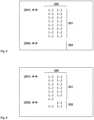
- FIG. 5 and the Figure 6A schematic view of an example of an assignment of path information to different transmission paths within a telecommunications network 100 is shown schematically. From the Figure 5 It can be seen that of the set of possible path information 350, a first subset 351 is assigned to the first transmission path 301 and a second subset 352 is assigned to the second transmission path. From the Figure 5 It can be seen that of the set of possible path information 350 (in the example comprising 16 indicated individual (identifiers of) path information), a first subset 351 assigned to the first transmission path in the example has all of these 16 indicated different (identifiers of) path information, while a second subset 352 assigned to the second transmission path 302 in the example is the empty set, ie has no path information.
- the set of possible path information 350in the example comprising 16 indicated individual (identifiers of) path information
- a first subset 351 assigned to the first transmission path in the examplehas all of these 16 indicated different (identifiers of) path information
- a first subset 351(in the example comprising 13 different (identifiers of) path information) is assigned to the first transmission path 301 and a second subset 352 (in the example comprising 3 different (identifiers of) path information) is assigned to the second transmission path 302.
- the Figures 5 and 6are an example of the assignment of (identifiers of) path information 350 to the individual transmission paths 301, 302 for different operating modes of the telecommunications network: For example, in the first operating mode, the assignment according to Figure 5 apply, while in the second operating mode the assignment is according to Figure 6 applies because in particular the bandwidth availability of the first transmission path 301 has decreased during the transition from the first operating mode to the second operating mode.
- a telecommunications network 100uses a combination of routing methods and flexible optical interfaces: Unlike conventional telecommunications networks, according to the invention the IP/MPLS traffic flows are no longer only identified by specifying the destination address of the output LER (ie the second edge network node 24, 34), but the same destination or the same combination of first edge network node 21, 31 and second edge network node 24, 34 is differentiated using a suitable set of additional distinguishing identifiers (ie different path information 350).
- the telecommunications network 100it is possible to operate the telecommunications network 100 normally (ie in a normal operating mode) in the same way as conventional telecommunications networks (ie the same combination of first edge network node 21, 31 and second edge network node 24, 34 is assigned one path information (and not a suitable set of different path information 350) (or the additional distinction between several path information 350 introduced (according to the invention) is ignored).
- the majority of different path informationis only taken into account in the event of an error (second operating mode) or the additional multiplicity of the path information with respect to that of the destinations plays a role and is used to deal with locally changed data transmission capacities.
- the IP routing mechanisms known from conventional telecommunications networksare expanded.
- a reference capacity of 400 Gbit/s in the optical interfaces, i.e. on the physical layeris assumed below.
- the smallest changes in bandwidth (i.e. a change in partial bandwidths) of 25 Gbit/sare provided (i.e. that each of the plurality of possible path information 350 corresponds to a partial bandwidth (fixed and the same for all path information) available on one of the transmission paths 301, 302 in the respective operating mode).
- 25 GBd chunks or partial bandwidths of 25 GBdare suitable because this seems particularly suitable for the smallest granularity at a gross symbol rate of around 28 GBd or corresponds to exactly one bit per symbol (the difference between 28 and 25 is explained by the additional overhead required for e.g. framing and forward error correction).
- this informationis distributed to all routers or network nodes of the telecommunications network 100 and used there in the same way (in the first operating mode, i.e.
- the label table in the edge router LER A in the above example according to the Figure 1therefore no longer contains just two entries for the destination LER E1 and for the first and second transmission paths 301, 302, but a total of 32, namely 16 for each of the transmission paths 301, 302.
- the next hopis not the intermediate network node LSR F, but the intermediate network node LSR B (assuming that only the topology shown is available and that the path via the intermediate network node LSR B also still has sufficient free capacity; however, the aspect of spare capacity must always be taken into account
- the exact method of determining and distributing these new pathsdoes not need to be explicitly specified at this point.
- the "k-shortest path” algorithmcan be used, for example, to determine how the new paths are determined. This is an extension of the classic shortest path search using well-known algorithms such as Dijkstra or Bellman-Ford.
- the "k-shortest path” algorithmcalculates not only the shortest path (or several equally short paths) based on a given topology and the costs for each path section, but also other non-shortest paths until a total of k alternative paths have been found. These paths are pre-calculated and can be assigned a "priority" or "preference” property, for example. Alternatively, it can also be provided that path costs are equated with hops; the standard paths are then the truly shortest paths and in the event of an error, a path that is one or two hops longer is used for the affected path sections. The complexity of these calculations is not necessarily greater than that of conventional routing calculations, because the "k-shortest path” algorithm only uses intermediate results that are needed for the "shortest path” routing anyway.
- the distribution to other pathswould therefore take place in such a way that for the number of nominally 25 Gbits/s units affected by the error - i.e. for each of which path information from the set of possible path information 350 exists - (in general: a subset of the k parts), a new entry is written into the forwarding table or an already preconfigured path is activated (i.e. instead of the first subset 351 (of path information) related to a specific first transmission path, the second subset 352 (of path information) related to a specific second transmission path is assigned).
- the table in the LSR Mwould then contain the resulting assignment in this network state (error case) or in this operating mode of the telecommunications network 100: 13 Path information is assigned to the transmission path via the intermediate network node LSR F, while 3 path information is assigned to the transmission path via the other intermediate network node (not shown). It is not absolutely necessary that the "shifted" path information (between the various transmission paths 351, 352) (or the associated "chunks" of partial bandwidths of an overall bandwidth availability) remain in the forwarding table in one piece, i.e. contiguous (with regard to their identifiers). Rather, these 25 Gbit/s chunks can be viewed completely independently of one another.
- the edge of the telecommunications network(between the intermediate network node LSR F and the intermediate network node LSR H) affected in the example (by a fault situation) is not only used by the traffic relationship between the edge router LER A and the edge router LER E1, but also a large number of other traffic requirements are routed via this edge, the same procedure is used for all of these traffic requirements, i.e.
- the affected number of partial bandwidths (or "chunks" of the required bandwidth requirement) - and thus the affected number of path information (or MPLS labels) -is routed via other IP capacities, whereby the units of 25 Gbit/s are only to be seen as a notional value, since no interface is usually driven to the capacity limit in regular operation; on the contrary, there is usually always a few percent "room” for improvement (necessarily in order to absorb peaks in the bandwidth requirement of the packet traffic). Depending on the planning specifications, this limit is around 80% of the nominal capacity. In addition, the contributions of the individual traffic relationships are not evenly distributed, but rather a statistical and dynamically changing mix can be found along the edges.
- the particular elegance of the method according to the inventionis that error handling generally only takes place within the network of edge network nodes or intermediate network nodes (i.e. the LSR network) and the error has no effect on the edge routers (LER). Even after an error, the edge routers assign the corresponding path information (or MPLS labels) for the source traffic assigned to them, which are expanded by a factor of k according to the invention. The edge routers (LER) do not even have to be informed of the error because they only have knowledge of the second edge router (i.e. the destination LER) anyway and are agnostic to the details of the routing in the core network.
- the assignment of the labels (or path information) in the edge router LERis independent of the assignment of the labels to specific paths (which, according to the invention, takes place in the edge network node). Therefore, no additional complex effort is required to take into account the distribution of the total traffic and the cross-relationships of the individual traffic requirements. Specifications and adjustments regarding other required properties such as "minimum runtime" or similar are initially not taken into account here, but can easily be added later. The preference for certain traffic shares in such a way that special (i.e. shorter) routes are specifically assigned would then correspond to an effective discrimination against other traffic and would have to be assessed from a regulatory perspective.
- the challenges to scalability and the required storage spacewill increase by this constant factor.
- thisis (always) less limiting.
- the "online" traffic engineering (TE) -i.e. during operation of the telecommunications network 100 - becomes significantly more efficient through the invention (in the sense of improved use of the network resources).
- an elastic transport networkin particular optical transport network
- IP layerpacket layer
- the k sublabelsor labels extended by a factor of k or the corresponding path information 350
- the bandwidths of the optical transportwhich fluctuate especially in the event of a fault, can be made usable for the packet layer in the first place.
Landscapes
- Engineering & Computer Science (AREA)
- Computer Networks & Wireless Communication (AREA)
- Signal Processing (AREA)
- Data Exchanges In Wide-Area Networks (AREA)
Description
Translated fromGermanDie Erfindung betrifft ein Verfahren zur effizienteren Datenübertragung in einem Telekommunikationsnetz, insbesondere beruhend auf optischen Datenübertragungskomponenten zum Wellenlängen-Multiplex-Betrieb (WDM, wavelength division multiplex) einer Mehrzahl von verschiedenen optischen Wellenlängen, wobei das Telekommunikationsnetz eine Mehrzahl von Netzknoten und zwischen den Netzknoten vorliegende Datenübertragungsstrecken aufweist.The invention relates to a method for more efficient data transmission in a telecommunications network, in particular based on optical data transmission components for wavelength division multiplexing (WDM) of a plurality of different optical wavelengths, wherein the telecommunications network has a plurality of network nodes and data transmission paths between the network nodes.
Die Erfindung betrifft ferner ein Telekommunikationsnetz zur effizienteren Datenübertragung in dem Telekommunikationsnetz, insbesondere beruhend auf optischen Datenübertragungskomponenten zum Wellenlängen-Multiplex-Betrieb (WDM, wavelength division multiplex) einer Mehrzahl von verschiedenen optischen Wellenlängen, wobei das Telekommunikationsnetz eine Mehrzahl von Netzknoten und zwischen den Netzknoten vorliegende Datenübertragungsstrecken aufweist.The invention further relates to a telecommunications network for more efficient data transmission in the telecommunications network, in particular based on optical data transmission components for wavelength division multiplexing (WDM) of a plurality of different optical wavelengths, wherein the telecommunications network has a plurality of network nodes and data transmission paths between the network nodes.
Ferner betrifft die Erfindung auch ein Computerprogramm mit Programmcodemitteln und ein Computerprogrammprodukt mit einem computerlesbaren Medium und einem auf dem computerlesbaren Medium gespeicherten Computerprogramm, die dazu geeignet sind, alle Schritte des erfindungsgemäßen Verfahrens auszuführen.Furthermore, the invention also relates to a computer program with program code means and a computer program product with a computer-readable medium and a computer program stored on the computer-readable medium, which are suitable for carrying out all steps of the method according to the invention.
Die
Bekannt und implementiert sind optische Telekommunikationsnetze, welche Netzbetreibern optische Weitverkehrsschnittstellen mit einer festen Datenraten anbieten, wobei jedoch auch optische Schnittstellen bzw. optische Übertragungstechnik bekannt sind bzw. ist, welche variable Datenraten verwenden und damit variable Datenübertragungsraten zur Verfügung stellen können. Technisch umgesetzt werden solche unterschiedlichen Datenübertragungsraten durch verschiedene Betriebsmodi, z.B. durch den Einsatz unterschiedlicher Modulationsformate (QPSK, 8QAM, 16QAM), durch Anpassen der Bandbreite eines optischen Signals (Änderung der sogenannten Baudrate) oder durch die Verteilung des Datenstroms auf mehrere gekoppelte Wellenlängen im Sinne eines sog. "sliceable bandwidth-variable transponder" (S-BVT). Eine besondere Form des ersten Ansatzes ist die sog. Hybrid Modulation (oder time division hybrid modulation, TDHM), bei der verschiedene Modulationsformen zu festen Zeitabschnitten alterniert werden. Durch geeignete Wahl der jeweiligen Zeitdauern lassen sich nahezu beliebige effektive Übertragungsraten erzeugen. Alle Varianten solcher Anpassungen in der optischen Übertragungsrate werden mit dem Begriff "FlexRate Schnittstelle" zusammengefasst.Optical telecommunications networks are known and implemented, which offer network operators optical wide area interfaces with a fixed data rate, although optical interfaces or optical transmission technology are also known or implemented which use variable data rates and can thus provide variable data transmission rates. Technically, such different data transmission rates are implemented using different operating modes, e.g. by using different modulation formats (QPSK, 8QAM, 16QAM), by adjusting the bandwidth of an optical signal (changing the so-called baud rate) or by distributing the data stream over several coupled wavelengths in the sense of a so-called "sliceable bandwidth-variable transponder" (S-BVT). A special form of the first approach is so-called hybrid modulation (or time division hybrid modulation, TDHM), in which different modulation forms are alternated at fixed time intervals. By choosing the appropriate time periods, almost any effective transmission rate can be generated. All variants of such adjustments in the optical transmission rate are summarized with the term "FlexRate interface".
Aufbauend auf einer physischen Schicht (physical layer/data link layer, gemäß dem OSI-Modell) - realisiert beispielsweise in Form eines optischen Telekommunikationsnetzes - wird in derzeitigen Telekommunikationsnetzen eine elektrische Paketverarbeitung vorgenommen, welche der Client-Layer der optisch bereitgestellten Übertragungskapazitäten darstellt. Der Client-Layer, die Ebene der elektrischen Paketverarbeitung (IP-Layer bzw. IP-Ebene bzw. Internet Protocol Ebene), erwartet jedoch typischerweise eine starre Datenrate im Transport. Aus Sicht der IP-Schicht wäre es sogar vorteilhaft, wenn eine optische Schnittstelle vollständig ausgeschaltet werden würde, anstatt sie mit reduzierter (aber immer noch optimaler) Kapazität weiter zu nutzen. Dies deshalb, weil auf der IP-Schicht in aller Regel IP/MPLS Mechanismen und Protokolle (Multi Protocol Label Switch Protokolle bzw. Mechanismen) in diversen Varianten eingesetzt werden. Eine Besonderheit dieser im OSI-Stack (bzw. im OSI-Modell) auf der Ebene 3 (network layer) angesiedelten Routing-Protokolle wie beispielsweise IGP oder BGP (Internal Gateway Protocol, Border Gateway Protocol) ist es, dass sie sich nur auf abstrakte Begriffe wie Knoten und Kanten abstützen, ohne den Kanten eigene Eigenschaften zuzugestehen. Das Internet Protokoll beispielsweise ist seinem Wesen nach ein Adresskonzept und es werden für die Wegesuche zwischen den Knoten Algorithmen und Protokolle wie z.B. OSPF bzw. ISIS eingesetzt (Open Shortest Path First; Inter System Inter System). Dabei ist nur entscheidend, ob es zwischen den Knoten einen Weg (d.h. eine Kante oder eine Abfolge von Kanten und Zwischenknoten) gibt oder nicht. Um einen optimalen Datenverkehr in einem Telekommunikationsnetz zu ermöglichen, wird üblicherweise Traffic Engineering eingesetzt, d.h. verschiedene Mechanismen und Methoden, um den Verkehrsfluss durch das Netz zu optimieren. Dabei wird ausgenutzt, dass es zwischen den festgelegten Quellen und Senken des Datenverkehrs (bzgl. einer gewissen Metrik) oft zueinander äquivalente Wege gibt. In solchen Situationen wird oftmals in den beteiligten Routern ein Mechanismus eingesetzt, der sich Equal Cost Multi Path (ECMP) nennt: Für alle Pakete zwischen (identischem) Sender und (identischem) Empfänger wird ein Hashwert über relevante Protokollfelder errechnet. Dazu werden die Headerfelder wie Quell- und Zieladresse (für IP) oder der TCP/UDP-Port (Transmission Control Protocol/User Datagram Protcol Port) herangezogen. Aus diesem Hashwert wird dann im nächsten Schritt mittels einer Modulo-Operation das (IP)-Ausgangsinterface für das betrachtete Paket (bzw. die betrachtete Gruppe von Datenpaketen bestimmt und damit der Weg durch das Netz festgelegt. Durch die Beachtung der Headerfelder ist sichergestellt, dass alle Pakete, die zur gleichen Gruppe gehören, d.h. insbesondere zum gleichen TCP-Flow gehören, den gleichen Weg durch das Netz nehmen. Dadurch wird Paket-Reordering, d.h. das Umsortieren von (in einer Gruppe zusammengehörenden) Paketen nach deren Empfang, vermieden. Die Verwendung des ECMP Protokolls setzt in der Regel voraus, dass die verschiedenen Wege (zwischen gleicher Quelle bzw. gleichem Quellenknoten einerseits und gleicher Senke bzw. gleichem Ziel bzw. gleichem Zielknoten andererseits) nicht nur bezüglich der Routing-Metrik exakt gleich sind (sonst gelten sie nicht als äquivalent), implizit wird in der Regel davon ausgegangen, dass die Wege sich hinsichtlich ihrer Übertragungsrate nicht maßgeblich unterscheiden dürfen. Dies ist in der Praxis nachteilig, weil dies einen enormen Optimierungsaufwand zu Folge hat, weil bei der Vergabe der Gewichte (Routing-Metriken) auf die einzelnen Kanten eine Vielzahl von Verkehrsbeziehungen und -bedarfe und sonstige Randbedingungen berücksichtigt werden müssen.Based on a physical layer (physical layer/data link layer, according to the OSI model) - implemented, for example, in the form of an optical telecommunications network - electrical packet processing is carried out in current telecommunications networks, which represents the client layer of the optically provided transmission capacities. However, the client layer, the level of electrical packet processing (IP layer or Internet Protocol level), typically expects a fixed data rate in transport. From the perspective of the IP layer, it would even be advantageous if an optical interface were switched off completely instead of continuing to use it with reduced (but still optimal) capacity. This is because IP/MPLS mechanisms and protocols (Multi Protocol Label Switch protocols or mechanisms) are generally used in various variants on the IP layer. A special feature of these routing protocols, such as IGP or BGP (Internal Gateway Protocol, Border Gateway Protocol), which are located in the OSI stack (or in the OSI model) at level 3 (network layer), is that they are based only on abstract concepts such as nodes and edges, without granting the edges their own properties. The Internet Protocol, for example, is essentially an address concept and algorithms and protocols such as OSPF or ISIS (Open Shortest Path First; Inter System Inter System) are used to find paths between the nodes. The only thing that matters is whether or not there is a path between the nodes (i.e. an edge or a sequence of edges and intermediate nodes). In order to enable optimal data traffic in a telecommunications network, traffic engineering is usually used, i.e. various mechanisms and methods to control the flow of traffic through the network. optimize. This takes advantage of the fact that there are often equivalent paths between the specified sources and sinks of the data traffic (with regard to a certain metric). In such situations, a mechanism called Equal Cost Multi Path (ECMP) is often used in the routers involved: For all packets between (identical) sender and (identical) receiver, a hash value is calculated using relevant protocol fields. The header fields such as source and destination address (for IP) or the TCP/UDP port (Transmission Control Protocol/User Datagram Protocol Port) are used for this purpose. In the next step, this hash value is used to determine the (IP) output interface for the packet under consideration (or the group of data packets under consideration) using a modulo operation, thus determining the path through the network. By observing the header fields, it is ensured that all packets that belong to the same group, i.e. in particular to the same TCP flow, take the same path through the network. This avoids packet reordering, i.e. the reordering of packets (that belong together in a group) after they have been received. The use of the ECMP protocol generally requires that the different paths (between the same source or source node on the one hand and the same sink or destination or destination node on the other) are not only exactly the same in terms of the routing metric (otherwise they are not considered equivalent), it is generally implicitly assumed that the paths must not differ significantly in terms of their transmission rate. This is disadvantageous in practice because it results in an enormous optimization effort, because a large number of traffic relationships and requirements and other boundary conditions must be taken into account when assigning the weights (routing metrics) to the individual edges.
Der Erfindung liegt die Aufgabe zugrunde, ein Verfahren und ein Telekommunikationsnetz zur Verfügung zu stellen, bei welchem in einfacher und flexibler Weise die Möglichkeiten, die durch moderne und eine flexible Datenrate aufweisende Datentransportschnittstellen, insbesondere optische Schnittstellen bzw. flexrate Schnittstellen, zur Verfügung gestellt werden, möglichst für das Telekommunikationsnetz insgesamt, d.h. insbesondere auch für die höheren Protokollschichten - insbesondere die IP-Ebene -, in vergleichsweise einfacher und robuster Weise nutzbar zu machen, so dass bei gleicher vorgegebener Ausfallsicherheit bzw. Datenübertragungskapazität in verschiedenen Betriebsmodi (insbesondere auch umfassend Fehlersituationen) das Telekommunikationsnetz kostengünstiger realisierbar ist bzw. bei gleichen Investitionskosten für das Telekommunikationsnetz eine schnellere Wiederherstellungszeit (in einen äquivalenten Betriebsmodus) bzw. mittelbar eine höhere Ausfallsicherheit und/oder eine höhere Datenübertragungskapazität und/oder eine höhere Flexibilität hinsichtlich der Netzwerk- und Verkehrssteuerung möglich ist.The invention is based on the object of providing a method and a telecommunications network in which the possibilities provided by modern data transport interfaces with a flexible data rate, in particular optical interfaces or flexrate interfaces, can be used in a simple and flexible manner for the telecommunications network as a whole, i.e. in particular also for the higher protocol layers - in particular the IP level - in a comparatively simple and robust manner, so that with the same specified reliability or data transmission capacity in different operating modes (in particular also including error situations), the Telecommunications network can be implemented more cost-effectively or, with the same investment costs for the telecommunications network, a faster recovery time (to an equivalent operating mode) or, indirectly, a higher level of reliability and/or a higher data transmission capacity and/or a higher flexibility with regard to network and traffic control is possible.
Diese Aufgabe wird erfindungsgemäß gelöst durch ein Verfahren zur effizienteren Datenübertragung in einem Telekommunikationsnetzgemäß Anspruch 1.This object is achieved according to the invention by a method for more efficient data transmission in a telecommunications network according to
Es ist dadurch gemäß der vorliegenden Erfindung in vorteilhafter Weise möglich, dass auch auf der IP-Ebene eines Telekommunikationsnetzes Möglichkeiten effektiv und vorteilhaft genutzt werden können, die aufgrund einer Elastizität (d.h. Variabilität bzw. Elastizität hinsichtlich der zur Verfügung stehenden Datenübertragungsbandbreite auf verschiedenen Pfaden bzw. Datenübertragungsstrecken bzw. -kanten) auf der Ebene der physischen Datenübertragung, insbesondere - für den Fall eines optischen Telekommunikationsnetz zu Bereitstellung der physischen Datenübertragung - auf dem optischen Transport-Layer durch optische Flexrate-Schnittstellen, möglich ist.According to the present invention, it is therefore advantageously possible that, even at the IP level of a telecommunications network, possibilities can be used effectively and advantageously which are possible due to elasticity (i.e. variability or elasticity with regard to the available data transmission bandwidth on different paths or data transmission links or edges) at the level of physical data transmission, in particular - in the case of an optical telecommunications network for providing physical data transmission - at the optical transport layer through optical Flexrate interfaces.
Erfindungsgemäß wird somit ein neuartiges Lastaufteilungsverfahren auf unsymmetrische Interfacekapazitäten in einem Telekommunikationsnetz, insbesondere in Telekommunikationsnetzen, welche eine IP-Ebene bzw. IP-Schicht aufweisen und insbesondere IP/MPLS-Protokolle nutzen, vorgeschlagen, um von den Vorteilen einer (insbesondere hinsichtlich der Übertragungsbandbreite) flexiblen Übertragungstechnik (insbesondere optischen flexiblen Übertragungstechnik) tatsächlich auch für die IP-Schicht des Telekommunikationsnetzes profitieren zu können.According to the invention, a novel load distribution method is proposed for asymmetrical interface capacities in a telecommunications network, in particular in telecommunications networks which have an IP level or IP layer and in particular use IP/MPLS protocols, in order to be able to actually benefit from the advantages of a flexible transmission technology (in particular with regard to the transmission bandwidth) (in particular optical flexible transmission technology) also for the IP layer of the telecommunications network.
Die Übertragungsraten solcher Telekommunikationsnetze werden sich typischerweise im Bereich von einigen 100 Gbit/s bis 1000 Gbit/s bewegen, wobei jedoch auch größere Übertragungsraten möglich sind. Ein typischer Umschaltevorgang (etwa einer Flexrate-Schnittstelle) könnte z.B. zwischen 200 Gbit/s und 100 Gbit/s stattfinden; es sind jedoch auch feiner abgestufte Kapazitätsgranularitäten eines Interfaces bzw. einer Schnittstelle denkbar.The transmission rates of such telecommunications networks will typically be in the range of a few 100 Gbit/s to 1000 Gbit/s, although higher transmission rates are also possible. A typical switching process (for example of a flexrate interface) could take place between 200 Gbit/s and 100 Gbit/s, for example; however, more finely graded capacity granularities of an interface are also conceivable.
Typischerweise umfasst der zentrale Teil eines Telekommunikationsnetzes (auch Kernnetz bzw. Core-Netz bzw. Backbone genannt) ein MPLS-Netz, wobei am Rand eines solchen Telekommunikationsnetzes (insbesondere der zentrale Teil eines durch einen Netzbetreiber betriebenen Telekommunikationsnetzes) sogenannte Randrouter bzw. Edge-Router platziert sind, die unter Verwendung von IP Adressen (d.h. gemäß des TCP/IP-Protokolls, insbesondere unter Verwendung von Routingmechanismen von einem Knoten zum nächsten) arbeiten. Innerhalb des zentralen Teils des Telekommunikationsnetzes (d.h. innerhalb des Core Netzes) werden sogenannte Label-Switch-Router (LSR) eingesetzt. Die Randrouter bzw. Edge Router am Rand des betrachteten Telekommunikationsnetzes nennt man auch Label Edge Router (LER). An die LER sind die Kundenlokationen (des Betreibers des Telekommunikationsnetzes) und deren Endgeräte angeschlossen, die die eigentlichen Bedarfsträger der Verkehrsbedarfe darstellen. In einem solchen Telekommunikationsnetz können die Randrouter typischerweise als die Quellen und Senken der Verkehrsflüsse im Core-Netz angesehen werden. Jeder Randrouter kennt alle an ihn angebundenen möglichen Ziele und hat für diese einen Adressbereich oder mehrere Adressbereiche, den bzw. die er allen anderen Randrouter über geeignete Protokolle mitteilt.Typically, the central part of a telecommunications network (also called core network or backbone) comprises an MPLS network, with so-called edge routers being placed at the edge of such a telecommunications network (in particular the central part of a telecommunications network operated by a network operator), which use IP addresses (i.e. according to the TCP/IP protocol, in particular using routing mechanisms from a node to the next). Within the central part of the telecommunications network (i.e. within the core network) so-called label switch routers (LSR) are used. The edge routers at the edge of the telecommunications network in question are also called label edge routers (LER). The customer locations (of the operator of the telecommunications network) and their end devices, which represent the actual users of the traffic requirements, are connected to the LER. In such a telecommunications network, the edge routers can typically be seen as the sources and sinks of the traffic flows in the core network. Each edge router knows all possible destinations connected to it and has one or more address ranges for these, which it communicates to all other edge routers via suitable protocols.
In einer beispielhaften Situation (vgl.
In herkömmlichen - insbesondere optischen bzw. auf optischer Datenübertragung beruhenden - Telekommunikationsnetzen ist es bekannt, vermaschte Topologien innerhalb des Telekommunikationsnetzes derart zu verwenden, dass zum Schutz des Netzes und zur Steigerung der Resilienz gegenüber Ausfällen das Verfahren der optischen Wiederherstellung bzw. "optical restoration" bzw. allgemeiner "optical recovery" eingesetzt wird: Im Falle eines Glasfaserbruchs werden die anfallenden Verkehrsbedarfe zunächst auf andere IP-Links umgeschaltet. Dafür muss ausreichend Ersatzkapazität vorgehalten werden. Nach der Umschaltung auf der IP-Ebene wird innerhalb der vorhandenen Glasfaserinfrastruktur für jede betroffene Wellenlänge ein neuer Lichtpfad gesucht, beleuchtet und eingepegelt. Dabei sind die neuen (optischen) Ersatzwege in der Regel länger als die ursprünglichen Lichtpfade, da der reguläre Netzbetrieb typischerweise auf die kürzesten Verbindungen hin optimiert ist. Der große Vorteil der Optical restoration/recovery ist, dass sich die IP-Topologie vor und nach dem Fehler nicht ändert und dass dieselben (vergleichsweise sehr teuren) optischen Schnittstellen wiederverwendet werden können. Ein Nachteil ist allerdings, dass sich wegen des längeren Weges die physischen Eigenschaften des optischen Pfades verschlechtern können. Das betrifft konkret das sog, optische-Signal-zu-Rausch-Verhältnis (Optical Signal to noise ratio, OSNR). Wird dieser Wert zu schlecht, kann der Empfänger das optische Signal nicht mehr hinreichend auslesen und interpretieren. Bei bisher eingesetzten Datenraten von 1 Gbit/s, 10 Gbit/s, 40 Gbit/s oder 100 Gbit/s konnte dies verkraftet werden, da in üblicherweise benutzten Telekommunikationsnetzen (etwa nationale Netze in Europa) genügend OSNR-Reserve vorhanden war; dies ist jedoch nicht mehr der Fall bei höheren Datenraten, insbesondere oberhalb von 100 Gbit/s, da in einer solchen Situation die Übertragungssysteme bzw. Empfängersysteme immer sensitiver gegenüber Änderungen des OSNR werden, bis schließlich keine Daten mehr übertragen werden können. Ferner ist es einer der grundlegenden Vorteile der Verwendung von FlexRate-Schnittstellen, dass im Normalbetrieb keine großen Systemreserven eingeplant werden müssen, weil sie die intrinsische Eigenschaft der Anpassungsfähigkeit ihrer Transportkapazität an die Qualität der Übertragungsstrecke aufweisen. Dies bedeutet, dass FlexRate-Schnittstellen besonders vorteilhaft eingesetzt werden können, wenn der OSNR-Wert beim Empfänger (bzw. der Empfängerschnittstelle) einen Schwellenwert unterschreitet, da auch in einer solchen Situation der (aufgrund einer optical restoration/recovery-Situation benutzte) neue Lichtpfad weiter betrieben werden kann, wenn auch mit einer verringerten Datenrate. Da auf der IP-Schicht bzw. IP-Ebene typischerweise davon ausgegangen wird - insbesondere bei Verwendung des ECMP-Protokolls -, dass die verschiedenen Wege (zwischen gleicher Quelle bzw. gleichem Quellenknoten einerseits und gleicher Senke bzw. gleichem Ziel bzw. gleichem Zielknoten andererseits) sich hinsichtlich ihrer Übertragungsrate nicht maßgeblich unterscheiden, ist die IP-Schicht (welche als Client-Schicht zur physischen Schicht fungiert) nicht auf diese prinzipiellen Fähigkeiten und Vorteile der (insbesondere optischen) physischen (Transport)Schicht ausgerichtet; somit ist die IP/MPLS-Schicht quasi "blind" gegenüber physischen Eigenschaften (wie insbesondere der Übertragungsbandbreite) einer physischen (Transport)Verbindung. Aufgrund der bekannten Anzahl der in einem Telekommunikationsnetz vorhandenen Randrouter (LER) lässt sich abschätzen, wie viele verschiedene Label (bzw. unterschiedliche Pfadinformationen) in Tabellen verwaltet werden müssen. In bisher üblichen Telekommunikationsnetzen wird davon ausgegangen, dass auf allen angebotenen Pfaden bzw. Links ausreichend Kapazität vorhanden ist. Damit das sichergestellt ist, ist bei herkömmlichen Telekommunikationsnetzen ein aufwendiges Monitoring der Auslastung notwendig und das sorgfältige Ausbalancieren der Gewichte der einzelnen Kanten im Load Balancing (denn das Gesamtgewicht eines Weges setzt sich aus der Summe der beteiligten Kanten zusammen). Es ist leicht einsehbar, dass dies ist ein sehr fragiles System ist, mit dem sehr behutsam umgegangen werden muss.In conventional telecommunications networks - especially optical or those based on optical data transmission - it is known to use meshed topologies within the telecommunications network in such a way that the process of optical restoration or "optical recovery" or more generally "optical recovery" is used to protect the network and increase resilience to failures: In the event of a fiber optic break, the resulting traffic requirements are first switched to other IP links. Sufficient replacement capacity must be kept available for this. After switching at the IP level, a new light path is sought, illuminated and leveled for each affected wavelength within the existing fiber optic infrastructure. The new (optical) replacement paths are usually longer than the original light paths, since regular network operation is typically optimized for the shortest connections. The great advantage of optical restoration/recovery is that the IP topology does not change before and after the error and that the same (comparatively very expensive) optical interfaces can be reused. One disadvantage, however, is that the physical properties of the optical path can deteriorate due to the longer path. This specifically affects the so-called optical signal to noise ratio (OSNR). If this value becomes too poor, the receiver can no longer adequately read and interpret the optical signal. With data rates of 1 Gbit/s, 10 Gbit/s, 40 Gbit/s or 100 Gbit/s used to date, this could be tolerated because there was sufficient OSNR reserve in commonly used telecommunications networks (such as national networks in Europe); however, this is no longer the case with higher data rates, especially above 100 Gbit/s, because in such a situation the transmission systems or receiver systems become increasingly sensitive to changes in the OSNR until finally no more data can be transmitted. Furthermore, one of the fundamental advantages of using FlexRate interfaces is that no large system reserves need to be planned for in normal operation, because they have the intrinsic property of being able to adapt their transport capacity to the quality of the transmission path. This means that FlexRate interfaces can be used particularly advantageously when the OSNR value at the receiver (or the receiver interface) falls below a threshold value, since even in such a situation the new light path (used due to an optical restoration/recovery situation) can continue to be operated, albeit with a reduced data rate. Since it is typically assumed at the IP layer or IP level - especially when using the ECMP protocol - that the various paths (between the same source or source node on the one hand and the same sink or destination or destination node on the other) do not differ significantly in terms of their transmission rate, the data rate of the different paths (between the same source or source node on the other hand and the same sink or destination or destination node on the other hand) is not significantly different from the data rate of the different paths (between the same source or source node on the one hand and the same sink or destination or destination node on the other hand) is not significantly different from the data rate of the different paths (between the same source or source node on the other hand) and the same sink or destination or destination node on the other hand). The IP layer (which acts as a client layer to the physical layer) is not geared towards these fundamental capabilities and advantages of the (especially optical) physical (transport) layer; thus the IP/MPLS layer is virtually "blind" to physical properties (such as the transmission bandwidth in particular) of a physical (transport) connection. Based on the known number of edge routers (LER) present in a telecommunications network, it is possible to estimate how many different labels (or different path information) must be managed in tables. In telecommunications networks that have been used up to now, it is assumed that there is sufficient capacity on all paths or links offered. To ensure this, conventional telecommunications networks require complex monitoring of the load and careful balancing of the weights of the individual edges in load balancing (because the total weight of a path is made up of the sum of the edges involved). It is easy to see that this is a very fragile system that must be handled very carefully.
Gemäß der vorliegenden Erfindung wird daher vorgeschlagen, dass in für MPLS-Telekommunikationsnetze an sich bekannter Weise für eine Gruppe von (zusammengehörenden) Nutzdatenpaketen eine Pfadinformation (zur Übertragung im Telekommunikationsnetz vom ersten Randnetzknoten zum zweiten Randnetzknoten) verwendet wird, wobei die einzelnen Nutzdatenpakete der Gruppe von Nutzdatenpakete wahlweise über (wenigstens) einen ersten Übertragungspfad oder einen zweiten Übertragungspfad übertragen werden können. Die Pfadinformation wird der Gruppe von Nutzdatenpaketen durch den ersten Randnetzknoten zugewiesen (bzw. durch den ersten Randnetzknoten bestimmt) und zwar in Abhängigkeit einerseits des zweiten Randnetzknotens (d.h. des Ziels bzw. des Zielnetzknotens der Gruppe von Nutzdatenpaketen) und andererseits in Abhängigkeit einer ersten Bandbreitenverfügbarkeit des ersten Übertragungspfades und einer zweiten Bandbreitenverfügbarkeit des zweiten Übertragungspfades. Erfindungsgemäß ist es nun vorgesehen, dass nicht lediglich eine einzige Pfadinformation (in Abhängigkeit vom ersten und zweiten Randnetzknoten), sondern eine Mehrzahl von möglichen Pfadinformationen für die Datenübertragung der Gruppe von Nutzdatenpaketen vom ersten Randnetzknoten zum zweiten Randnetzknoten generiert oder aktualisiert werden bzw. existieren. Die Generierung der Mehrzahl von möglichen Pfadinformationen (MPLS-Labels) wird erfindungsgemäß bei der Konfiguration des Telekommunikationsnetzes bzw. von dessen Netzknoten vorgenommen (durch einen der beteiligten Netzknoten oder aber durch eine andere Instanz) bzw. es wird die Generierung der Mehrzahl von möglichen Pfadinformationen (MPLS-Labels) im Zuge einer Aktualisierung bzw. Änderung des Telekommunikationsnetzes (mittels insbesondere einer Aktualisierung bzw. Änderung einer Tabelle von Pfadinformationen) vorgenommen, etwa wenn ein neuer Netzknoten zum Telekommunikationsnetz hinzugefügt wird. Die erfindungsgemäß vorliegende Mehrzahl von möglichen Pfadinformationen (für das gleiche Paar von Eingangsnetzknoten und Ausgangsnetzknoten)
- -- umfasst eine dem ersten Übertragungspfad zugeordnete erste Teilmenge von Pfadinformationen und eine dem zweiten Übertragungspfad zugeordnete (und von der ersten Teilmenge disjunkte) zweite Teilmenge von Pfadinformationen, oder
- -- entspricht der dem ersten Übertragungspfad zugeordneten ersten Teilmenge von Pfadinformationen.
Erfindungsgemäß ist nun vorgesehen, dass in einem ersten Betriebsmodus des Telekommunikationsnetzes die den Nutzdatenpaketen der betrachteten Gruppe von Nutzdatenpaketen zugeordnete Pfadinformation einer Datenübertragung über den ersten Übertragungspfad entspricht und in einem zweiten Betriebsmodus des Telekommunikationsnetzes die (gleiche) den Nutzdatenpaketen der betrachteten Gruppe von Nutzdatenpaketen zugeordnete Pfadinformation einer Datenübertragung über den zweiten Übertragungspfad entspricht (insbesondere deshalb, weil sich die erste Bandbreitenverfügbarkeit (für die Datenübertragung über den ersten Übertragungspfad im zweiten Betriebsmodus von derjenigen im ersten Betriebsmodus unterscheidet, nämlich verringert hat), d.h. ein erster Teil der Nutzdatenpakete der Gruppe von Nutzdatenpakten wird (während des Vorliegens des ersten Betriebsmodus des Telekommunikationsnetzes) über den ersten Übertragungspfad übertragen, während ein zweiter Teil der Nutzdatenpakte der Gruppe von Nutzdatenpakten wird (während des Vorliegens des zweiten Betriebsmodus des Telekommunikationsnetzes) über den zweiten Übertragungspfad übertragen. Dies korrespondiert damit, dass die der betrachteten Gruppe von Nutzdatenpaketen zugeordnete Pfadinformation nach dem Übergang vom ersten Betriebsmodus in den zweiten Betriebsmodus nicht mehr der ersten Teilmenge von Pfadinformationen, sondern der zweiten Teilmenge von Pfadinformationen zugeordnet ist. Diese Änderung der Zuordnung zur ersten bzw. zweiten Teilmenge von Pfadinformationen findet bei einer Änderung des Betriebsmodus des Telekommunikationsnetzes jeweils im ersten Schritt statt (falls sich die Änderung des Betriebsmodus auf die betrachtete Mehrzahl von Pfadinformation auswirkt). Im zweiten Schritt wird sodann (insbesondere für den Fall, dass einer (neuen) Gruppe von Nutzdatenpaketen (etwa aufgrund einer neu gestarteten Kommunikationsdienstanfrage eines Nutzers des Telekommunikationsnetzes) eine Pfadinformation zugeordnet werden muss bzw. für diese (neue) Gruppe von Nutzdatenpakten eine (bzw. "ihre") Pfadinformation bestimmt werden muss) eine Pfadinformation zur Übertragung der (neuen) Gruppe von Nutzdatenpaketen - aus der Mehrzahl von möglichen Pfadinformationen - bestimmt, wobei die (gleiche dieser (neuen) Gruppe von Nutzdatenpaketen zugeordnete) Pfadinformation im ersten Betriebsmodus Element der dem ersten Übertragungspfad zugeordneten ersten Teilmenge der Mehrzahl von Pfadinformationen und im zweiten Betriebsmodus (nach der Generierung oder Aktualisierung - im beim Übergang auf den zweiten Betriebsmodus durchgeführten ersten Schritt - der Zuordnung der betrachteten Mehrzahl von möglichen Pfadinformationen zur ersten bzw. zweiten Teilmenge von Pfadinformationen) Element der dem zweiten Übertragungspfad zugeordneten zweiten Teilmenge der Mehrzahl von Pfadinformationen ist.According to the present invention, it is therefore proposed that, in a manner known per se for MPLS telecommunications networks, path information (for transmission in the telecommunications network from the first edge network node to the second edge network node) is used for a group of (related) user data packets, wherein the individual user data packets of the group of user data packets can be transmitted optionally via (at least) a first transmission path or a second transmission path. The path information is assigned to the group of user data packets by the first edge network node (or determined by the first edge network node) depending on the second edge network node (i.e. the destination or destination network node of the group of user data packets) on the one hand and on a first bandwidth availability of the first transmission path and a second bandwidth availability of the second transmission path on the other. According to the invention, it is now provided that not just a single path information (depending on the first and second edge network nodes), but a plurality of possible path information for the data transmission of the group of user data packets from the first edge network node to the second edge network node is generated or updated or exists. The generation of the plurality of possible path information (MPLS labels) is carried out according to the invention during the configuration of the telecommunications network or its network nodes (by one of the network nodes involved or by another instance) or the generation of the plurality of possible path information (MPLS labels) is carried out in the course of an update or change of the telecommunications network (in particular by means of an update or change of a table of path information), for example when a new Network node is added to the telecommunications network. The plurality of possible path information (for the same pair of input network nodes and output network nodes)
- -- comprises a first subset of path information associated with the first transmission path and a second subset of path information associated with the second transmission path (and disjoint from the first subset), or
- -- corresponds to the first subset of path information associated with the first transmission path.
According to the invention, it is now provided that in a first operating mode of the telecommunications network, the path information assigned to the payload data packets of the group of payload data packets under consideration corresponds to a data transmission via the first transmission path and in a second operating mode of the telecommunications network, the (same) path information assigned to the payload data packets of the group of payload data packets under consideration corresponds to a data transmission via the second transmission path (in particular because the first bandwidth availability (for data transmission via the first transmission path in the second operating mode differs from that in the first operating mode, namely has decreased), i.e. a first part of the payload data packets of the group of payload data packets is transmitted via the first transmission path (while the first operating mode of the telecommunications network is present), while a second part of the payload data packets of the group of payload data packets is transmitted via the second transmission path (while the second operating mode of the telecommunications network is present). This corresponds to the fact that the path information assigned to the group of user data packets under consideration is no longer assigned to the first subset of path information after the transition from the first operating mode to the second operating mode, but to the second subset of path information. This change in the assignment to the first or second subset of path information takes place in the first step when the operating mode of the telecommunications network changes (if the Change of the operating mode affects the majority of path information considered). In the second step, path information for transmitting the (new) group of payload data packets is then determined from the majority of possible path information (particularly in the event that a (new) group of payload data packets (for example due to a newly initiated communication service request from a user of the telecommunications network) has to be assigned path information or (or "its") path information has to be determined for this (new) group of payload data packets), whereby the path information (the same path information assigned to this (new) group of payload data packets) is an element of the first subset of the majority of path information assigned to the first transmission path in the first operating mode and an element of the second subset of the majority of path information assigned to the second transmission path in the second operating mode (after the generation or updating - in the first step carried out when switching to the second operating mode - of the assignment of the majority of possible path information considered to the first or second subset of path information).
Hierdurch ist es erfindungsgemäß in vorteilhafter Weise möglich, dass - nach einem Übergang (bzw. während oder im Zuge des Übergangs) vom ersten zum zweiten Betriebsmodus - durch eine einfache Änderung der Zuordnung der (der jeweiligen Gruppe von Nutzdatenpakten zugeordneten) Pfadinformation zur ersten bzw. zweiten Teilmenge von Pfadinformationen auf eine Änderung der ersten bzw. zweiten Bandbreitenverfügbarkeit reagiert werden kann und somit in einfacher und flexibler Weise eine Anpassung der Verteilung der Verkehrsströme realisierbar ist, insbesondere ohne die Notwendigkeit einer aufwändigen und gegebenenfalls riskanten Änderung von Konfigurationsparametern des Telekommunikationsnetzes auf einer vergleichsweise niedrigen (bzw. die physischen Leitungsparameter der Übertragungsstrecke betreffenden) Ebene, etwa zur Änderung von Parametern der verwendeten Routingmetriken.This makes it possible in an advantageous manner according to the invention that - after a transition (or during or in the course of the transition) from the first to the second operating mode - a simple change in the assignment of the path information (assigned to the respective group of user data packets) to the first or second subset of path information can be used to react to a change in the first or second bandwidth availability, and thus an adjustment of the distribution of the traffic flows can be implemented in a simple and flexible manner, in particular without the need for a complex and possibly risky change of configuration parameters of the telecommunications network at a comparatively low level (or relating to the physical line parameters of the transmission link), for example to change parameters of the routing metrics used.
Wie bereits ausgeführt ist es gemäß einer Ausführungsform der Erfindung vorgesehen, dass im ersten Betriebsmodus des Telekommunikationsnetzes die dem zweiten Übertragungspfad zugeordnete zweite Teilmenge die leere Menge ist, was letztlich äquivalent dazu ist, dass die Mehrzahl von möglichen Pfadinformationen der dem ersten Übertragungspfad zugeordneten ersten Teilmenge von Pfadinformationen entspricht.As already stated, according to one embodiment of the invention, in the first operating mode of the telecommunications network, the second subset assigned to the second transmission path is the empty set, which is ultimately equivalent to the majority of possible path information corresponding to the first subset of path information assigned to the first transmission path.
Hierdurch ist es erfindungsgemäß in vorteilhafter Weise möglich, dass im ersten Betriebsmodus (welcher beispielsweise einem Normalbetriebsmodus des Telekommunikationsnetzes entspricht) das Telekommunikationsnetz derart betrieben werden kann, dass die zweite Teilmenge von Pfadinformationen keine Rolle spielt, was wiederum dazu führt, dass letztlich die betrachtete Mehrzahl von Pfadinformationen (d.h. eine Mehrzahl von Kennungen) zu einer einzigen (dem Pfad vom ersten Randnetzknoten zum zweiten Randnetzknoten entsprechenden) Pfadinformation zusammenschrumpfen kann.This makes it possible in an advantageous manner according to the invention that in the first operating mode (which corresponds, for example, to a normal operating mode of the telecommunications network) the telecommunications network can be operated in such a way that the second subset of path information plays no role, which in turn leads to the fact that ultimately the considered majority of path information (ie a majority of identifiers) can be reduced to a single path information (corresponding to the path from the first edge network node to the second edge network node).
Erfindungsgemäß ist es bevorzugt vorgesehen, dass im ersten Betriebsmodus des Telekommunikationsnetzes die der ersten Teilmenge zugeordnete Mehrzahl von möglichen Pfadinformationen jeweils eine erste Teilpfadinformation und eine zweite Teilpfadinformation umfassen, wobei die erste Teilpfadinformation der der ersten Teilmenge zugeordneten möglichen Pfadinformationen jeweils identisch ist und wobei die zweite Teilpfadinformation der der ersten Teilmenge zugeordneten möglichen Pfadinformationen einen Informationsinhalt von 2 Bit oder von 3 Bit oder von 4 Bit oder von 5 Bit oder von 6 Bit, bevorzugt von 4 Bit, aufweist, wobei im ersten Betriebsmodus des Telekommunikationsnetzes insbesondere lediglich die erste Teilpfadinformation der Mehrzahl von möglichen Teilpfadinformationen ausgewertet wird.According to the invention, it is preferably provided that in the first operating mode of the telecommunications network, the plurality of possible path information items assigned to the first subset each comprise a first partial path information item and a second partial path information item, wherein the first partial path information item of the possible path information items assigned to the first subset is identical in each case and wherein the second partial path information item of the possible path information items assigned to the first subset has an information content of 2 bits or 3 bits or 4 bits or 5 bits or 6 bits, preferably 4 bits, wherein in the first operating mode of the telecommunications network, in particular only the first partial path information item of the plurality of possible partial path information items is evaluated.
Dadurch, dass die erste Teilpfadinformation der der ersten Teilmenge zugeordneten Pfadinformationen jeweils identisch ist, ist es erfindungsgemäß in einfacher Weise möglich, (im ersten Betriebsmodus) die betrachtete Mehrzahl von Pfadinformationen (d.h. die Mehrzahl von Kennungen) zu einer einzigen Pfadinformation (bzw. einer einzigen Kennung) zusammenzuschrumpfen, nämlich indem lediglich die erste Teilpfadinformation (d.h. der der ersten Teilpfadinformation entsprechende (identische) Teil der Kennungen der ersten Teilmenge von Pfadinformationen) als die einzige Pfadinformation herangezogen (bzw. ausgewertet) wird (und mithin die jeweiligen (sich jeweils innerhalb Pfadinformationen der ersten Teilmenge unterscheidenden) zweiten Teilpfadinformationen unberücksichtigt gelassen werden). Letztlich ist es beispielsweise vorgesehen, dass zur Definition der Pfadinformationen (gesamte) Kennungen umfassend beispielsweise 10 Bit oder von 16 Bit oder von 20 Bit oder von 24 Bit vorgesehen sind, wobei für die zweite Teilpfadinformation der Pfadinformationen 2 Bit oder 3 Bit oder 4 Bit oder 5 Bit oder 6 Bit, insbesondere 4 Bit, vorgesehen sind (insbesondere die jeweils niederwertigen Bits) und wobei für die erste Teilpfadinformation der Pfadinformationen die restlichen (insbesondere höherwertigen bzw. höherstelligen) Bits vorgesehen sind (d.h. im Fall von 20 Bits für die Definition der Kennung der gesamten Pfadinformation und 4 Bits für die zweite Teilpfadinformation stehen für die erste Teilpfadinformation 16 Bits zur Verfügung).Because the first partial path information is identical to the path information assigned to the first subset, it is possible in a simple manner according to the invention to shrink the considered plurality of path information (i.e. the plurality of identifiers) into a single path information (or a single identifier) (in the first operating mode), namely by only using (or evaluating) the first partial path information (i.e. the (identical) part of the identifiers of the first subset of path information corresponding to the first partial path information) as the only path information (and thus ignoring the respective second partial path information (which differs within the path information of the first subset). Ultimately, it is provided, for example, that (total) identifiers comprising, for example, 10 bits or 16 bits or 20 bits or 24 bits are provided for defining the path information, with 2 bits or 3 bits or 4 bits or 5 bits or 6 bits, in particular 4 bits, being provided for the second partial path information of the path information (in particular the respective low-order bits) and with the remaining (in particular higher-order or higher-digit) bits being provided for the first partial path information of the path information (i.e. in the case of 20 bits for defining the identifier of the entire path information and 4 bits for the second partial path information, 16 bits are available for the first partial path information).
Ferner ist es erfindungsgemäß bevorzugt vorgesehen, dass in einem dem ersten Schritt vorangehenden dritten Schritt und während das Telekommunikationsnetz im zweiten Betriebsmodus betrieben wird, der erste Randnetzknoten eine Information erhält, wonach die im zweiten Betriebsmodus vorliegende erste Bandbreitenverfügbarkeit des ersten Übertragungspfades im Vergleich zur im ersten Betriebsmodus vorliegenden ersten Bandbreitenverfügbarkeit des ersten Übertragungspfades verringert ist und zumindest ein Teil der Mehrzahl von Pfadinformationen anstelle der dem ersten Übertragungspfad zugeordneten ersten Teilmenge der dem zweiten Übertragungspfad zugeordneten zweiten Teilmenge zugeordnet wird.Furthermore, it is preferably provided according to the invention that in a third step preceding the first step and while the telecommunications network is operated in the second operating mode, the first edge network node receives information according to which the first bandwidth availability of the first transmission path present in the second operating mode is reduced in comparison to the first bandwidth availability of the first transmission path present in the first operating mode and at least one Part of the plurality of path information is assigned to the second subset assigned to the second transmission path instead of the first subset assigned to the first transmission path.
Hierdurch ist es erfindungsgemäß in vorteilhafter Weise möglich, dass - nach einem Übergang vom ersten zum zweiten Betriebsmodus - durch eine einfache Änderung der Zuordnung der (der jeweiligen Gruppe von Nutzdatenpakten zugeordneten) Pfadinformation zur ersten bzw. zweiten Teilmenge von Pfadinformationen (im vorliegend betrachteten Fall eine Änderung der Zuordnung dahingehend, dass eine zuvor (d.h. während des Vorliegens des ersten Betriebsmodus) der ersten Teilmenge zugeordnete oder zugehörige Pfadinformation danach (d.h. während des Vorliegens des zweiten Betriebsmodus) der zweiten Teilmenge zugeordnet ist) auf eine Änderung der ersten bzw. zweiten Bandbreitenverfügbarkeit (hier: der Verringerung der ersten Bandbreitenverfügbarkeit) reagiert werden kann.This makes it possible in an advantageous manner according to the invention that - after a transition from the first to the second operating mode - a simple change in the assignment of the path information (assigned to the respective group of user data packets) to the first or second subset of path information (in the case considered here, a change in the assignment such that path information previously assigned to the first subset (i.e. during the presence of the first operating mode) or associated with it is subsequently assigned to the second subset (i.e. during the presence of the second operating mode)) can be used to react to a change in the first or second bandwidth availability (here: the reduction in the first bandwidth availability).
Erfindungsgemäß ist es ferner bevorzugt vorgesehen, dass sich der erste Übertragungspfad und der zweite Übertragungspfad wenigstens in der Benutzung eines unterschiedlichen optischen Weges und/oder in der Benutzung von unterschiedlichen optischen Wellenlängen zwischen wenigstens zwei Netzknoten der Mehrzahl von Netzknoten unterscheiden.According to the invention, it is further preferably provided that the first transmission path and the second transmission path differ at least in the use of a different optical path and/or in the use of different optical wavelengths between at least two network nodes of the plurality of network nodes.
Erfindungsgemäß ist es ferner bevorzugt vorgesehen, dass jede der Mehrzahl von möglichen Pfadinformationen einer auf einem der Übertragungspfade im jeweiligen Betriebsmodus verfügbaren Teilbandbreite entspricht, wobei als Teilbandbreite insbesondere eine für jede der Mehrzahl von möglichen Pfadinformationen feste Teilbandbreite von 1 GBd, 5 GBd, 10 GBd, 15 GBd, 20 GBd, 25 GBd, 30 GBd, 35 GBd, 40 GBd, 50 GBd, 60 GBd, 70 GBd, 80 GBd, 90 GBd oder 100 GBd entspricht.According to the invention, it is further preferably provided that each of the plurality of possible path information corresponds to a partial bandwidth available on one of the transmission paths in the respective operating mode, wherein the partial bandwidth in particular corresponds to a partial bandwidth of 1 GBd, 5 GBd, 10 GBd, 15 GBd, 20 GBd, 25 GBd, 30 GBd, 35 GBd, 40 GBd, 50 GBd, 60 GBd, 70 GBd, 80 GBd, 90 GBd or 100 GBd that is fixed for each of the plurality of possible path information.
Hierdurch ist es erfindungsgemäß in vorteilhafter Weise möglich, dass der Mehrzahl von möglichen Pfadinformationen einer vorgegebenen (und bevorzugt innerhalb der Mehrzahl der Pfadinformationen gleichen) "Bandbreiteneinheit" bzw. Teilbandbreite entspricht. Dadurch ist es erfindungsgemäß in einfacher und flexibler Weise möglich, die Belastung bzw. Beaufschlagung der verschiedenen Übertragungspfade innerhalb des Telekommunikationsnetzes mit bestimmten Verkehren bzw. mit einer bestimmten Verkehrslast in Abhängigkeit der auf ihnen zur Verfügung stehenden Bandbreitenverfügbarkeit vorzunehmen, wobei die Belastung der Übertragungspfade jeweils in Abstufungen von einer Teilbandbreite oder aber einer Mehrzahl von Teilbandbreiten vorgenommen werden kann. Dadurch ist sowohl eine flexible als auch eine einfache Verteilung der Verkehrslast und somit eine möglichst vollständige Auslastung der verschiedenen zur Verfügung stehenden Übertragungspfade (ohne eine Gefahr ihrer Überlastung) erfindungsgemäß möglich.This makes it possible in an advantageous manner according to the invention for the majority of possible path information to correspond to a predetermined (and preferably identical within the majority of path information) "bandwidth unit" or partial bandwidth. This makes it possible in a simple and flexible manner according to the invention to load or apply certain traffic or a certain traffic load to the various transmission paths within the telecommunications network depending on the bandwidth availability available on them, whereby the load on the transmission paths can be carried out in gradations of a partial bandwidth or a plurality of partial bandwidths. This enables both a flexible and simple distribution of the traffic load and thus the fullest possible utilization of the different available transmission paths (without any risk of overloading them) is possible according to the invention.
Erfindungsgemäß ist es insbesondere vorgesehen, dass die Mehrzahl von möglichen Pfadinformationen - und damit auch die Pfadinformation - eine Labelinformation eines MPLS (Multi Protocol Label Switched) Telekommunikationsnetzes sind oder eine analoge andere Protokoll-Suite als Basisinformationsgrundlage zur Verteilung und bzgl. des Formats von Labeln und Label-Informationen nutzen.According to the invention, it is particularly provided that the majority of possible path information - and thus also the path information - is label information of an MPLS (Multi Protocol Label Switched) telecommunications network or uses an analogous other protocol suite as a basic information basis for the distribution and with regard to the format of labels and label information.
Ferner ist es gemäß einer Ausführungsform der Erfindung vorgesehen, dass der erste Übertragungspfad und/oder der zweite Übertragungspfad entweder lediglich den ersten und zweiten Randnetzknoten sowie eine Datenübertragungsstrecke zwischen beiden oder aber den ersten und zweiten Randnetzknoten sowie wenigstens einen weiteren Netzknoten der Mehrzahl von Netzknoten sowie eine Mehrzahl von Datenübertragungsstrecken umfasst.Furthermore, according to an embodiment of the invention, it is provided that the first transmission path and/or the second transmission path either only comprises the first and second edge network nodes and a data transmission path between the two or the first and second edge network nodes and at least one further network node of the plurality of network nodes and a plurality of data transmission paths.
Ein weiterer Gegenstand der vorliegenden Erfindung ist ein Telekommunikationsnetz zur effizienteren Datenübertragung im Telekommunikationsnetzgemäß Anspruch 8.Another object of the present invention is a telecommunications network for more efficient data transmission in the telecommunications network according to claim 8.
Es ist hierdurch erfindungsgemäß - auch mit Bezug auf das Telekommunikationsnetz - vorteilhaft möglich, dass auch auf der IP-Ebene des erfindungsgemäßen Telekommunikationsnetzes Möglichkeiten effektiv und vorteilhaft genutzt werden können, die aufgrund einer Elastizität auf der Ebene der physischen Datenübertragung, insbesondere der optischen Datenübertragung, möglich ist.This makes it advantageously possible according to the invention - also with reference to the telecommunications network - that possibilities can also be used effectively and advantageously at the IP level of the telecommunications network according to the invention, which are possible due to an elasticity at the level of physical data transmission, in particular optical data transmission.
Ferner ist es erfindungsgemäß - auch mit Bezug auf das Telekommunikationsnetz - bevorzugt vorgesehen, dass im ersten Betriebsmodus des Telekommunikationsnetzes die dem zweiten Übertragungspfad zugeordnete zweite Teilmenge die leere Menge ist oder die Mehrzahl von möglichen Pfadinformationen der dem ersten Übertragungspfad zugeordneten ersten Teilmenge von Pfadinformationen entspricht.Furthermore, according to the invention - also with reference to the telecommunications network - it is preferably provided that in the first operating mode of the telecommunications network the second subset assigned to the second transmission path is the empty set or the majority of possible path information corresponds to the first subset of path information assigned to the first transmission path.
Ferner ist es erfindungsgemäß - auch mit Bezug auf das Telekommunikationsnetz - bevorzugt, dass im ersten Betriebsmodus des Telekommunikationsnetzes die der ersten Teilmenge zugeordnete Mehrzahl von möglichen Pfadinformationen jeweils eine erste Teilpfadinformation und eine zweite Teilpfadinformation umfassen, wobei die erste Teilpfadinformation der der ersten Teilmenge zugeordneten möglichen Pfadinformationen jeweils identisch ist und wobei die zweite Teilpfadinformation der der ersten Teilmenge zugeordneten möglichen Pfadinformationen einen Informationsinhalt von 2 Bit oder von 3 Bit oder von 4 Bit oder von 5 Bit oder von 6 Bit, bevorzugt von 4 Bit, aufweist, wobei im ersten Betriebsmodus des Telekommunikationsnetzes insbesondere lediglich die erste Teilpfadinformation der Mehrzahl von möglichen Teilpfadinformationen ausgewertet wird.Furthermore, it is preferred according to the invention - also with reference to the telecommunications network - that in the first operating mode of the telecommunications network, the plurality of possible path information items assigned to the first subset each comprise a first partial path information item and a second partial path information item, wherein the first partial path information item of the possible path information items assigned to the first subset is identical in each case and wherein the second partial path information item of the possible path information items assigned to the first subset has an information content of 2 bits or 3 bits or 4 bits or 5 bits or 6 bits, preferably 4 bits, wherein in the first operating mode of the telecommunications network, in particular only the first partial path information of the majority of possible partial path information is evaluated.
Ferner bezieht sich die vorliegende Erfindung auch auf ein Computerprogramm mit Programmcodemitteln, mit deren Hilfe alle Schritte des erfindungsgemäßen Verfahrens durchführbar sind, wenn das Computerprogramm auf einer programmierbaren Einrichtung und/oder einem Netzknoten eines Telekommunikationsnetzes ausgeführt wird.Furthermore, the present invention also relates to a computer program with program code means with the aid of which all steps of the method according to the invention can be carried out when the computer program is executed on a programmable device and/or a network node of a telecommunications network.
Weiterhin ist Gegenstand der vorliegenden Erfindung ein Computerprogrammprodukt mit einem computerlesbaren Medium und einem auf dem computerlesbaren Medium gespeicherten Computerprogramm mit Programmcodemitteln, die dazu geeignet sind, dass alle Schritte des erfindungsgemäßen Verfahrens durchführbar sind, wenn das Computerprogramm auf einer programmierbaren Einrichtung und/oder Netzknoten eines Telekommunikationsnetzes ausgeführt wird.Furthermore, the present invention relates to a computer program product with a computer-readable medium and a computer program stored on the computer-readable medium with program code means which are suitable for all steps of the method according to the invention to be carried out when the computer program is executed on a programmable device and/or network node of a telecommunications network.
Weitere Einzelheiten, Merkmale und Vorteile der Erfindung ergeben sich aus den Zeichnungen, sowie aus der nachfolgenden Beschreibung von bevorzugten Ausführungsformen anhand der Zeichnungen. Die Zeichnungen illustrieren dabei lediglich beispielhafte Ausführungsformen der Erfindung, welche den wesentlichen Erfindungsgedanken nicht einschränken.Further details, features and advantages of the invention emerge from the drawings and from the following description of preferred embodiments with reference to the drawings. The drawings merely illustrate exemplary embodiments of the invention which do not restrict the essential inventive concept.
- Figur 1Figure 1
- zeigt eine schematische Ansicht eines beispielhaften Telekommunikationsnetzes mit verschiedenen Netzknoten und Randroutern.shows a schematic view of an exemplary telecommunications network with various network nodes and edge routers.
- Figur 2Figure 2
- zeigt eine schematische Ansicht eines anderen beispielhaften Telekommunikationsnetzes mit verschiedenen Netzknoten, wobei jedoch die Randrouter nicht dargestellt sind.shows a schematic view of another exemplary telecommunications network with various network nodes, but the edge routers are not shown.
- Figuren 3 und 4Figures 3 and 4
- zeigen schematische Ansichten eines in verschiedenen Betriebsmodi betriebenen Telekommunikationsnetzes mit verschiedenen Netzknoten, wobei jedoch die Randrouter nicht dargestellt sind.show schematic views of a telecommunications network operated in different operating modes with different network nodes, although the edge routers are not shown.
- Figuren 5 und 6Figures 5 and 6
- zeigen zwei schematische Beispiele von Zuordnungen von Pfadinformationen zu verschiedenen Übertragungspfaden innerhalb eines Telekommunikationsnetzes.show two schematic examples of assignments of path information to different transmission paths within a telecommunications network.
In den verschiedenen Figuren sind gleiche Teile stets mit den gleichen Bezugszeichen versehen und werden daher in der Regel auch jeweils nur einmal benannt bzw. erwähnt.In the various figures, identical parts are always provided with the same reference symbols and are therefore usually named or mentioned only once.
In
In bekannter Weise lassen sich damit innerhalb von MPLS-Netzen vergleichsweise leicht IP Resilienz-Mechanismen implementieren, denn falls ein Link zwischen zwei Zwischennetzknoten unterbrochen wird, kann der betreffende Netzknoten die Nutzdatenpakete (bzw. Gruppe von Nutzdatenpaketen) mit einem neuen Label einfach an einen anderen Zwischennetzknoten schicken, welcher das Nutzdatenpaket (bzw. die Gruppe von Nutzdatenpaketen) dann (aufgrund der mit dem Nutzdatenpaket bzw. der Gruppe verbundenen und vom ersten Randnetzknoten vergebenen Pfadinformation) korrekt weiterroutet. Jeder Netzknoten hat die notwendige Information darüber, welches Label (bzw. welche Pfadinformation) für welches Ziel bei seinen direkt benachbarten Netzknoten nötig ist. Für das bekannte ECMP-Verfahren werden die verschiedenen Übertragungspfadalternativen (also gleich langen bzw. gleich teuren) Wege nur anhand der (vom ersten Randnetzknoten vergebenen) Labels bzw. Pfadinformationen voneinander unterschieden. Falls ein ein Netzknoten also zu einem Ziel mehr als einen Weg kennt, die alle zueinander äquivalent sind, wird als Modulo-Operand die Anzahl der Ausgangsschnittstellen des Netzknotens verwendet, die gerade den verschiedenen Pfadinformationen (bzw. MPLS-Labels) entsprechen.In a known way, IP resilience mechanisms can be implemented relatively easily within MPLS networks, because if a link between two intermediate network nodes is interrupted, the network node in question can simply send the payload packets (or group of payload packets) with a new label to another intermediate network node, which then correctly routes the payload packet (or group of payload packets) (based on the path information associated with the payload packet or group and assigned by the first edge network node). Each network node has the necessary information about which label (or path information) is required for which destination at its directly neighboring network nodes. For the well-known ECMP method, the various transmission path alternatives (i.e. paths of equal length or cost) are only differentiated from one another based on the labels or path information (assigned by the first edge network node). If a network node knows more than one path to a destination, all of which are equivalent to one another, the number of output interfaces of the network node that correspond to the various path information (or MPLS labels) is used as the modulo operand.
Die sowohl in der
Damit dies sichergestellt ist, wird in bekannten bzw. herkömmlichen Telekommunikationsnetzen ein aufwendiges Monitoring der Auslastung mit Blick auf ein sorgfältiges Ausbalancieren der Gewichte der einzelnen Kanten im Load Balancing (denn das Gesamtgewicht eines Weges setzt sich aus der Summe der beteiligten Kanten zusammen) vorgenommen. Typischerweise werden Änderungen im Traffic Engineering vor einer faktischen Ausführung in komplexen Verkehrs- und Lastsimulationen untersucht. Ferner ist es bei bekannten Telekommunikationsnetzen möglich, dass - um alle auftretenden (Verkehrs)Bedarfe effizient und kostengünstig zu erfüllen - auch externe Nebenbedingungen beachtet werden, die von außerhalb des eigenen Netzes kommen und nicht beeinflusst werden können (insbesondere sogenannte Transit- oder Peeringverkehre, die von anderen Netz-Providern (bzw. Telekommunikationsnetzen) in das betroffene (bzw. betrachtete) Telekommunikationsnetz (IP Netz) eingespeist werden. Hierbei ist es bekannt, das sogenannte Segment Routing einzusetzen, d.h. es werden nicht nur die Ziel- und Transitknoten (Router bzw. Netzknoten) mit einem eindeutigen Kennzeichnung (bzw. einem Label) identifiziert (und für die Wegesuche berücksichtigt), sondern es wird auch einzelnen Kanten (zwischen den Netzknoten) ein Label zugewiesen. Anhand solcher Pfadinformation (bzw. Label) für Knoten und Kanten ist es möglich, dass konkrete Wege im Telekommunikationsnetz explizit eindeutig angegeben werden können, indem man die gewünschte Abfolge von Segmenten (also Knoten oder Kanten) in der Pfadinformation (insbesondere in Form von übereinander gestackten Protokollheadern) anführt.To ensure this, complex monitoring of the load is carried out in known or conventional telecommunications networks with a view to carefully balancing the weights of the individual edges in load balancing (because the total weight of a path is made up of the sum of the edges involved). Typically, changes in traffic engineering are examined in complex traffic and load simulations before they are actually implemented. Furthermore, in known telecommunications networks it is possible that - in order to meet all (traffic) requirements efficiently and cost-effectively - external constraints are also taken into account that come from outside the network and cannot be influenced (in particular so-called transit or peering traffic that is fed into the affected (or considered) telecommunications network (IP network) by other network providers (or telecommunications networks). In this case, it is known to use so-called segment routing, i.e. not only are the destination and transit nodes (routers or network nodes) identified with a unique identifier (or label) (and taken into account for the route search), but individual Edges (between the network nodes) are assigned a label. Using such path information (or labels) for nodes and edges, it is possible to specify specific paths in the telecommunications network explicitly and unambiguously by specifying the desired sequence of segments (i.e. nodes or edges) in the path information (particularly in the form of protocol headers stacked on top of each other).
Ein Beispiel hierfür wird bei dem in
Die bei herkömmlichen Telekommunikationsnetzen angewandten Routingverfahren innerhalb der IP-Schicht (bzw. des IP Layer) lassen es nicht zu, die Möglichkeiten der Elastizität auf der physikalischen Schicht (insbesondere eine optischen Übertragungsschicht) effektiv und vorteilhaft zu nutzen. Dies wird anhand der
Die Darstellung in
The representation in
Falls nun angenommen wird,
- -- dass die Auslastung der IP-Links vor dem Fehler bei 80% der IP Kapazität liegt und die Schnittstellen eine nominelle Datenrate von 400Gbit/s haben (d.h. es liegt eine Arbeitslast von jeweils 320 Gbit/s für den ersten und zweiten
Übertragungspfad wobei die Übertragungspfade - -- dass nach (bzw. mit) dem Fehler die Übertragungsrate des ersten Übertragungspfades 301 nur noch bei 300 Gbit/s liegt,
- -- that the utilization of the IP links before the error is 80% of the IP capacity and the interfaces have a nominal data rate of 400 Gbit/s (ie there is a workload of 320 Gbit/s each for the first and
second transmission paths 301, 302 - whereby thetransmission paths - -- that after (or with) the error, the transmission rate of the
first transmission path 301 is only 300 Gbit/s,
In der
Gemäß der vorliegenden Erfindung wird bei einem Telekommunikationsnetz 100 eine Kombination von Routingverfahren und flexiblen optischen Schnittstellen vorgenommen: Anders als bei herkömmlichen Telekommunikationsnetzen werden erfindungsgemäß die IP/MPLS Verkehrsströme nicht mehr nur über die Angabe der Ziel-Adresse des Ausgangs LER (d.h. des zweiten Randnetzknotens 24, 34) identifiziert, sondern es wird das gleiche Ziel bzw. die gleiche Kombination von erstem Randnetzknoten 21, 31 und zweitem Randnetzknoten 24, 34 mit einer geeigneten Menge an zusätzlichen Unterscheidungskennern (d.h. verschiedenen Pfadinformationen 350) unterschieden.According to the present invention, a
Insbesondere ist es erfindungsgemäß gemäß einer Variante der Erfindung möglich, das Telekommunikationsnetz 100 im Regelfall (d.h. in einem Normalbetriebsmodus) genauso zu betrieben wie herkömmliche Telekommunikationsnetze (d.h. der gleichen Kombination von erstem Randnetzknoten 21, 31 und zweitem Randnetzknoten 24, 34 wird eine Pfadinformation (und nicht eine geeignete Menge an verschiedenen Pfadinformationen 350) zugeordnet (bzw. die zusätzlich (erfindungsgemäß) eingeführte Unterscheidung mehrerer Pfadinformationen 350 wird ignoriert). Gemäß einer solchen Variante der Erfindung wird die Mehrzahl an verschiedenen Pfadinformationen erst im Fehlerfall (zweiter Betriebsmodus) berücksichtigt bzw. spielt die zusätzliche Vielfachheit der Pfadinformationen bezüglich der der Ziele eine Rolle und wird eingesetzt, um mit lokal geänderten Datenübertragungskapazitäten umzugehen.
Gemäß einer weiteren Variante der Erfindung ist es jedoch auch möglich, das Telekommunikationsnetz 100 bereits im Regelfall (d.h. im ersten Betriebsmodus) mit der Mehrzahl von Pfadinformationen zu betreiben.In particular, according to a variant of the invention, it is possible to operate the
According to a further variant of the invention, however, it is also possible to operate the
Für die Umsetzung der allgemeinen erfindungsgemäßen Idee werden die aus herkömmlichen Telekommunikationsnetzen, insbesondere MPLS-Telekommunikationsnetzen, bekannten IP-Routingmechanismen erweitert. Lediglich beispielhaft wird im Folgenden von einer Referenzkapazität von 400Gbit/s in den optischen Schnittstellen, d.h. auf der physischen Schicht ausgegangen. Ferner wird im Folgenden Beispielhaft davon ausgegangen, dass kleinste Änderungen der Bandbreite (d.h. eine Änderung von Teilbandbreiten) von 25Gbit/s vorgesehen sind (d.h. dass jede der Mehrzahl von möglichen Pfadinformationen 350 einer auf einem der Übertragungspfade 301, 302 im jeweiligen Betriebsmodus verfügbaren (festen und für alle Pfadinformationen gleiche) Teilbandbreite entspricht). Obwohl andere Zahlenwerte nicht ausgeschlossen werden sollen, bietet sich die Verwendung von 400 Gbit/s (oder GBd) und 25 Gbit/s (bzw. GBd) deshalb an, weil sich damit die Gesamtbandbreite einer, auf der IP-Ebene ansprechbaren Schnittstelle mit insgesamt 16 Teilbandbreiten ergibt, d.h. bei k = 16 Chunks (engl. "Brocken", d.h. Brocken von Teilbandbreiten) für eine Gesamtkapazität einer auf IP-Ebene ansprechbaren Schnittstelle ist es beispielsweise möglich, dass als die einzelnen Teilbandbreiten durch eine einzige Hexadezimalziffer im Hexadezimalsystem (d.h. durch 4 Bit) identifiziert werden können. Außerdem bieten sich 25GBd Chunks bzw. Teilbandbreiten von 25 GBd an, weil dies besonders geeignet erscheint, einer kleinsten Granularität bei einer Brutto-Symbolrate von ca. 28GBd zu entsprechen bzw. dann genau einem Bit pro Symbol entspricht (der Unterschied zwischen 28 und 25 erklärt sich durch den zusätzlich benötigten Overhead für z.B. Framing und Forward Error Correction). Kleinste relative Granularitäten (bzw. Teilbandbreiten) von weniger als 1/16 pro optischem Träger sind bei Mehrträger-Signalen sowohl bei 400Gbits als auch bei 1 000Gbit/s nicht zu erwarten, jedoch ist es erfindungsgemäß möglich, eine größere Anzahl als k = 16 verschiedene Teilbandbreiten pro über die IP-Schicht ansprechbarer Schnittstelle vorzusehen, insbesondere k = 32 verschiedene Teilbandbreiten (d.h. es sind zu deren Kodierung 5 Bit notwendig) bzw. k = 64 (d.h. es sind zu deren Kodierung 6 Bit notwendig). Im Folgenden wird jedoch beispielhaft von k = 16 ausgegangen.To implement the general inventive idea, the IP routing mechanisms known from conventional telecommunications networks, in particular MPLS telecommunications networks, are expanded. For example only, a reference capacity of 400 Gbit/s in the optical interfaces, i.e. on the physical layer, is assumed below. Furthermore, it is assumed below, by way of example, that the smallest changes in bandwidth (i.e. a change in partial bandwidths) of 25 Gbit/s are provided (i.e. that each of the plurality of
Um zum Beispiel gemäß der
In einem größeren MPLS-basierten Kernnetz würde die Verteilung auf andere Pfade also so geschehen, dass für die vom Fehler betroffene Anzahl von nominell 25Gbits/s-Einheiten - d.h. für die jeweils eine Pfadinformation aus der Menge der möglichen Pfadinformationen 350 existiert - (allgemein: einer Untermenge der k Anteile) ein neuer Eintrag in die Forwardingtabelle geschrieben wird oder aber ein bereits vorkonfigurierter Pfad aktiviert wird (d.h. statt der auf einen bestimmten ersten Übertragungspfad bezogenen ersten Teilmenge 351 (von Pfadinformationen) der auf einen bestimmten zweiten Übertragungspfad bezogenen zweiten Teilmenge 352 (von Pfadinformationen) zugeordnet wird). Diese Einträge können dann auch mittels Segment Routing längere Wege repräsentieren, die durch das herkömmliche IP-Routing (Pfad mit minimalem Gewicht) nicht in Betracht gekommen wären. Daher steht Segment Routing in natürlicher symbiotischer Beziehung zu der vorliegenden Erfindung. Im Beispiel etwa der
In a larger MPLS-based core network, the distribution to other paths would therefore take place in such a way that for the number of nominally 25 Gbits/s units affected by the error - i.e. for each of which path information from the set of
Da die im Beispiel (durch eine Fehlersituation) beeinträchtigte Kante des Telekommunikationsnetzes (zwischen dem Zwischennetzknoten LSR F und dem Zwischennetzknoten LSR H) nicht nur von der Verkehrsbeziehung zwischen dem Randrouter LER A und dem Randrouter LER E1 genutzt wird, sondern über diese Kante auch noch eine Vielzahl weiterer Verkehrsbedarfe geführt wird, wird für alle diese Verkehrsbedarfe das gleiche Verfahren angewendet, d.h. es wird die betroffene Anzahl an Teilbandbreiten (bzw. "Chunks" des benötigten Bandbreitenbedarfs) - mithin die betroffene Anzahl an Pfadinformationen (bzw. von MPLS-Labels) - über andere IP-Kapazitäten abgeführt, wobei die Einheiten von 25Gbit/s dabei nur als gedankliche Größe zu sehen sind, denn in der Regel wird kein Interface im regulären Betrieb bis an die Auslastungsgrenze gefahren; im Gegenteil sind in der Regel immer einige Prozent "Luft" nach oben (notwendigerweise, um Spitzen im Bandbreitenbedarf des Paketverkehres abzufangen). Je nach Planungsvorgabe liegt diese Grenze bei etwa 80% der nominellen Auslastung. Außerdem sind die Beiträge der einzelnen Verkehrsbeziehungen auch nicht gleichverteilt, sondern man findet entlang der Kanten einen statistischen und dynamisch veränderlichen Mix. Dies gilt nicht nur für die Zusammensetzung der Summenbandbreiten in der Richtung von einem Randrouter zu einem Rand- oder Zwischennetzknoten (d.h. LER zu LSR, d.h. in uplink-Richtung) des Telekommunikationsnetzes 100, sondern mit hinreichender Genauigkeit auch für die Verteilung innerhalb der Einheiten bzw. Teilbandbreiten (bzw. "Chunks") von 25Gbit/s. Die aktuell eingesetzten Hashing-Algorithmen sind so weit entwickelt und die Entropie der Protokollheader ist bei aggregierten Verkehren bis auf pathologische Fälle ausreichend groß, um eine nahezu gleiche Verteilung zwischen den Ausgangschnittstellen zu erreichen. Alles zusammen hat zur Folge, dass sich die restlichen Einheiten (bzw. "Chunks") von 25 Gbit/s Teilbandbreite die verbleibende Kapazität aller optischen Links teilen können und dass die neu zu verteilenden "Überschuss-Chunks" leicht auf die Ersatz-Kanten verteilt werden können (wie angedeutet, solange die Worst Case-Ersatzkapazität planerisch berücksichtigt ist, was in der Regel der Fall ist).Since the edge of the telecommunications network (between the intermediate network node LSR F and the intermediate network node LSR H) affected in the example (by a fault situation) is not only used by the traffic relationship between the edge router LER A and the edge router LER E1, but also a large number of other traffic requirements are routed via this edge, the same procedure is used for all of these traffic requirements, i.e. the affected number of partial bandwidths (or "chunks" of the required bandwidth requirement) - and thus the affected number of path information (or MPLS labels) - is routed via other IP capacities, whereby the units of 25 Gbit/s are only to be seen as a notional value, since no interface is usually driven to the capacity limit in regular operation; on the contrary, there is usually always a few percent "room" for improvement (necessarily in order to absorb peaks in the bandwidth requirement of the packet traffic). Depending on the planning specifications, this limit is around 80% of the nominal capacity. In addition, the contributions of the individual traffic relationships are not evenly distributed, but rather a statistical and dynamically changing mix can be found along the edges. This applies not only to the composition of the total bandwidths in the direction from an edge router to an edge or intermediate network node (ie LER to LSR, i.e. in the uplink direction) of the
Die besondere Eleganz des erfindungsgemäßen Verfahrens besteht darin, dass die Fehlerbehandlung in der Regel nur innerhalb des Netzes der Randnetzknoten bzw. Zwischennetzknoten (d.h. dem LSR-Netz) stattfindet und der Fehler keine Auswirkung auf die Randrouter (LER) hat. Die Randrouter vergeben auch nach einem Fehler für die ihnen zugeordneten Quellverkehre die entsprechenden Pfadinformationen (bzw. MPLS-Labels), die erfindungsgemäß um den Faktor k erweitertet werden. Die Randrouter (LER) müssen über den Fehler noch nicht einmal informiert werden, weil sie sowieso nur Kenntnisse über den zweiten Randrouter (d.h. den Ziel-LER) haben und agnostisch gegenüber den Details der Wegeführung im Kernnetz sind. Die Vergabe der Label (bzw. der Pfadinformationen) im Randrouter LER ist unabhängig von der Zuordnung der Label auf konkrete Pfade (welche erfindungsgemäß im Randnetzknoten stattfindet). Deshalb muss kein zusätzlicher komplexer Aufwand betrieben werden, um die Verteilung des Gesamtverkehrs und die Querbeziehungen der einzelnen Verkehrsbedarfe zu berücksichtigen. Vorgaben und Anpassungen bzgl. weiterer geforderter Eigenschaften wie z.B. "minimale Laufzeit" oder ähnliches bleiben hier zunächst unberücksichtigt, können aber leicht nachgetragen werden. Die Bevorzugung bestimmter Verkehrsanteile in der Weise, dass gezielt besondere (i.e. kürzere) Wege zugewiesen werden, entspräche dann einer effektiven Diskriminierung der anderen Verkehre und müsste aus Regulierungssicht bewertet werden. Des Weiteren ist die Wahl der Chunk-Proportionierung ein globaler Wert des Netzes (er ergibt sich aus dem Quotienten der kleinsten wählbaren Datenratengranularität elastischer Interface und der nominell größten eingesetzten Schnittstellenübertragungsrate im Netz). Will man von Ausbaustufen und zukünftigen Entwicklungen im Netz unabhängig sein, kann man auch eine feste kleinste Chunkbreite von z.B. 5 Gbits/s festlegen. Eintreffender Verkehr muss dann individuell pro Eingangs-Schnittstelle im Router gehashed und in 5 Gbit/s Chunks eingeteilt werden. Bei einem 40Gbit/s Interface ergäben also 8 Chunks. Ein Wert von maximal K = 16 wird hier aber als realistisch angesehen.The particular elegance of the method according to the invention is that error handling generally only takes place within the network of edge network nodes or intermediate network nodes (i.e. the LSR network) and the error has no effect on the edge routers (LER). Even after an error, the edge routers assign the corresponding path information (or MPLS labels) for the source traffic assigned to them, which are expanded by a factor of k according to the invention. The edge routers (LER) do not even have to be informed of the error because they only have knowledge of the second edge router (i.e. the destination LER) anyway and are agnostic to the details of the routing in the core network. The assignment of the labels (or path information) in the edge router LER is independent of the assignment of the labels to specific paths (which, according to the invention, takes place in the edge network node). Therefore, no additional complex effort is required to take into account the distribution of the total traffic and the cross-relationships of the individual traffic requirements. Specifications and adjustments regarding other required properties such as "minimum runtime" or similar are initially not taken into account here, but can easily be added later. The preference for certain traffic shares in such a way that special (i.e. shorter) routes are specifically assigned would then correspond to an effective discrimination against other traffic and would have to be assessed from a regulatory perspective. Furthermore, the choice of chunk proportioning is a global value of the network (it results from the quotient of the smallest selectable data rate granularity of elastic interfaces and the nominally largest interface transmission rate used in the network). If you want to be independent of expansion stages and future developments in the network, you can also specify a fixed smallest chunk width of e.g. 5 Gbits/s. Incoming traffic must then be hashed individually for each input interface in the router and divided into 5 Gbit/s chunks. For a 40 Gbit/s interface, this would result in 8 chunks. However, a maximum value of K = 16 is considered realistic here.
Mit dem in der Erfindung vorgeschlagenen Ansatz ist es erstmalig möglich, flexible Bandbreiten im Transport (L0, L1) für den Router-Layer überhaupt und vorteilhaft nutzbar zu machen. Damit können deutliche Auslastungsverbesserungen bei zukünftigen Interfacen/Transpondern mit flexiblen Datenraten erzielt werden. Diese höheren Auslastungen teurer Weitverkehrsinterface führen zu kostengünstigeren Netzimplementierungen. Das kann zwar besonders vorteilhaft im Fehlerfall bei "optisch elastischen Netzen" (EON) ausgenutzt werden. Es kann aber auch generell bei Kapazitätsunsymmetrien paralleler IP Links - auch im Normalfall - verwendet werden. Dieser Fall tritt im normalen Netzbetrieb immer dann auf, wenn mehrere Interface mit unterschiedlichen, aber konstanten Kapazitäten (also keine FlexRate Schnittstellen) verwendet werden, z.B. bei der Neuinstallation einer festen 100 Gbit/s Schnittstelle parallel zu einer bestehenden festen 10 Gbit/s Schnittstelle. Im herkömmlichen Betriebsmodus müssen die bestehenden 10 Gbit/s Schnittstellen abgeschaltet werden. Um die Netzkosten für einen Netzbetreiber dennoch in einem akzeptablen Rahmen zu halten, werden die ausgemusterten Interface mit erheblichem Personalaufwand möglichst zu einem anderen Router transportiert und dort wiederverwendet.With the approach proposed in the invention, it is possible for the first time to make flexible bandwidths in transport (L0, L1) usable for the router layer at all and advantageously. This can achieve significant improvements in the utilization of future interfaces/transponders with flexible data rates. This higher utilization of expensive wide area interfaces leads to more cost-effective network implementations. This can be used particularly advantageously in the event of a fault in "optically elastic networks" (EON). However, it can also be used generally in the event of capacity asymmetries of parallel IP links - even in normal cases. This case always occurs in normal network operation when several interfaces with different but constant capacities (i.e. no FlexRate interfaces) are used, e.g. when installing a new fixed 100 Gbit/s interface in parallel. to an existing fixed 10 Gbit/s interface. In conventional operating mode, the existing 10 Gbit/s interfaces must be switched off. In order to keep the network costs for a network operator within an acceptable range, the decommissioned interfaces are transported to another router and reused there, where possible, with considerable personnel expenditure.
Gemäß der vorliegenden Erfindung sind die Forwarding-Tabellen in den Routern um einen Faktor k (in den Beispielen k = 16) größer aus (maximal um den Faktor, der sich aus einem Verhältnis der größten Übertragungsrate der Schnittstellen im Vergleich zur kleinsten kontrollierbaren Bandbreitenänderung (bzw. Teilbandbreite) ergibt). Um diesen konstanten Faktor werden sich die Herausforderungen an die Skalierbarkeit und an den benötigten Speicherplatz verschärfen. Das ist jedoch bei der ständig wachsenden Performance der verfügbaren Router-Hardware (mit einer deutlich verbesserten Nutzbarkeit von großen Forwarding-Tabellen) (immer) weniger limitierend. Das "online" Traffic Engineering (TE) - d.h. während des Betriebs des Telekommunikationsnetzes 100 - wird durch die Erfindung deutlich effizienter (im Sinn einer verbesserten Verwendung der Netzresourcen).According to the present invention, the forwarding tables in the routers are larger by a factor k (in the examples k = 16) (maximum by the factor resulting from a ratio of the largest transfer rate of the interfaces compared to the smallest controllable bandwidth change (or partial bandwidth)). The challenges to scalability and the required storage space will increase by this constant factor. However, with the constantly increasing performance of the available router hardware (with a significantly improved usability of large forwarding tables), this is (always) less limiting. The "online" traffic engineering (TE) - i.e. during operation of the telecommunications network 100 - becomes significantly more efficient through the invention (in the sense of improved use of the network resources).
Insgesamt ist es gemäß der vorliegenden Erfindung möglich, durch eine geeignete Erweiterung bestehender MPLS-Label das Ziel zu erreichen, die Granularitäten eines elastischen Transportnetzes (insbesondere optischen Transportnetzes) auch für den Paket-Layer (IP-Layer)' vorteilhaft nutzbar zu machen. Hierzu werden die k Unterlabels (oder um den Faktor k erweiterte Labels bzw. die entsprechenden Pfadinformationen 350) erzeugt. Auf dieser Basis können die speziell im Fehlerfall schwankenden Bandbreiten des optischen Transports für den Paket-Layer überhaupt erst nutzbar gemacht werden.Overall, according to the present invention, it is possible to achieve the goal of making the granularities of an elastic transport network (in particular optical transport network) advantageously usable for the packet layer (IP layer) by a suitable extension of existing MPLS labels. For this purpose, the k sublabels (or labels extended by a factor of k or the corresponding path information 350) are generated. On this basis, the bandwidths of the optical transport, which fluctuate especially in the event of a fault, can be made usable for the packet layer in the first place.
Claims (12)
- Method for more efficient data transmission in a telecommunications network (100), in particular based on optical data transmission components for wavelength division multiplex, WDM, operation of a plurality of different optical wavelengths, the telecommunications network (100) having a plurality of network nodes (21-25, 31-36) and data transmission routes (1, 2, 3, 4, 5) between the network nodes (21-25, 31-36),wherein a piece of path information (310) is used for transmitting a group of payload data packets (300) in the telecommunications network (100) along a transmission path between a first network boundary node (21, 31) and a second network boundary node (24, 34) of the plurality of network nodes (21-25, 31-36),wherein the telecommunications network (100) has at least a first transmission path (301) and a second transmission path (302) for transmitting the group of payload packets (300) from the first network boundary node (21, 31) to the second network boundary node (24, 34),wherein the piece of path information (310) assigned to the group of payload data packets (300) is determined by the first network boundary node (21, 31) as a function of the second network boundary node (24, 34) and as a function of a first bandwidth availability of the first transmission path (301) and a second bandwidth availability of the second transmission path (302) in the telecommunications network (100) between the first network boundary node (21, 31) and the second network boundary node (24, 34),wherein the telecommunications network (100) is operable in a first operating mode and in a second operating mode, at least one of the first and the second bandwidth availability in the second operating mode differing from that in the first operating mode,wherein the method has the following steps:- in a first step, in the telecommunications network (100), a plurality of possible pieces of path information (350) for the data transmission of the group of payload data packets (300) from the first network boundary node (21, 31) to the second network boundary node (24, 34) are generated or updated, the plurality of possible pieces of path information (350) comprising a first subset (351) of pieces of path information, which is assigned to the first transmission path (301), and a second subset (352) of pieces of path information, which is assigned to the second transmission path (302) and is disjoint from the first subset (351), or the plurality of possible pieces of path information (350) corresponds to the first subset (351) assigned to the first transmission path (301), the assignment of the plurality of pieces of path information (350) to the first or to the second subset (351, 352) being dependent on the operating mode of the telecommunication network (100),- in a second step following the first step, the piece of path information (310) for transmitting the group of payload data packets (300) is determined among the plurality of possible pieces of path information (350), the piece of path information (310) being, in the first operating mode, an element of the first subset (351) of the plurality of path information (350), which is assigned to the first transmission path (301), and, in the second operating mode, an element of the second subset (352) of the plurality of path information (350), which is assigned to the second transmission path (302),wherein the plurality of possible pieces of path information (350) - and thus also the piece of path information (310) - are label information of a multiprotocol label switching, MPLS, telecommunications network.
- Method according to claim 1,characterised in that, in the first operating mode of the telecommunications network (100), the second subset (352) assigned to the second transmission path (302) is the empty set, or the plurality of possible pieces of path information (350) corresponds to the first subset (351) of pieces of path information, which is assigned to the first transmission path (301).
- Method according to either of the preceding claims,characterised in that, in the first operating mode of the telecommunications network (100), the plurality of possible pieces of path information (350) assigned to the first subset (351) each comprise a first sub-piece of path information and a second sub-piece of path information, the first sub-piece of path information of the possible pieces of path information (350) assigned to the first subset (351) being identical in each case, and the second sub-piece of path information of the possible pieces of path information (350) assigned to the first subset (351) having an information content of 2 bits or 3 bits or 4 bits or 5 bits or 6 bits, preferably 4 bits, in particular merely the first sub-piece of path information of the plurality of possible sub-pieces of path information (350) being evaluated in the first operating mode of the telecommunications network (100).
- Method according to any of the preceding claims,characterised in that, in a third step preceding the first step and while the telecommunications network (100) is being operated in the second operating mode, the first network boundary node (21, 31) receives a piece of information, whereby the first bandwidth availability of the first transmission path (301) in the second operating mode is reduced by comparison with the first bandwidth availability of the first transmission path (301) in the first operating mode and at least some of the plurality of pieces of path information (350) are assigned to the second subset (352) assigned to the second transmission path (302) instead of the first subset (351) assigned to the first transmission path (301).
- Method according to any of the preceding claims,characterised in that the first transmission path (301) and the second transmission path (302) differ at least in the use of a different optical pathway and/or in the use of different optical wavelengths between at least two network nodes of the plurality of network nodes (21-25, 31-36).
- Method according to any of the preceding claims,characterised in that each of the plurality of possible pieces of path information (350) corresponds to a sub-bandwidth available on one of the transmission paths (301, 302) in the associated operating mode, in particular a sub-bandwidth, which is fixed for each of the plurality of possible pieces of path information (350), of 1 GBd, 5 GBd, 10 GBd, 15 GBd, 20 GBd, 25 GBd, 30 GBd, 35 GBd, 40 GBd, 50 GBd, 60 GBd, 70 GBd, 80 GBd, 90 GBd or 100 GBd, serving as a sub-bandwidth.
- Method according to any of the preceding claims,characterised in that the first transmission path (301) and/or the second transmission path (302) either comprise merely the first and the second network boundary node (21, 31, 24, 34) and a data transmission route (1, 2, 3, 4, 5) between the two or else comprise the first and the second network boundary node (21, 31, 24, 34) and at least one further network node of the plurality of network nodes (21-25, 31-36) and a plurality of data transmission routes (1, 2, 3, 4, 5).
- Telecommunications network (100) for more efficient data transmission in a telecommunications network (100), in particular based on optical data transmission components for wavelength division multiplex, WDM, operation of a plurality of different optical wavelengths, the telecommunications network (100) having a plurality of network nodes (21-25, 31-36) and data transmission routes (1, 2, 3, 4, 5) between the network nodes (21-25, 31-36), wherein a piece of path information (310) is used for transmitting a group of payload data packets (300) in the telecommunications network (100) along a transmission path between a first network boundary node (21, 31) and a second network boundary node (24, 34) of the plurality of network nodes (21-25, 31-36),wherein the telecommunications network (100) has at least a first transmission path (301) and a second transmission path (302) for transmitting the group of payload packets (300) from the first network boundary node (21, 31) to the second network boundary node (24, 34),wherein the telecommunications network (100) is configured in such a way that the piece of path information (310) assigned to the group of payload data packets (300) is determined by the first network boundary node (21, 31) as a function of the second network boundary node (24, 34) and as a function of a first bandwidth availability of the first transmission path (301) and a second bandwidth availability of the second transmission path (302) in the telecommunications network (100) between the first network boundary node (21, 31) and the second network boundary node (24, 34),wherein the telecommunications network (100) is operable in a first operating mode and in a second operating mode, at least one of the first and the second bandwidth availability in the second operating mode differing from that in the first operating mode,wherein the the telecommunications network (100) is further configured in such a way that:- in the telecommunications network (100), a plurality of possible pieces of path information (350) for the data transmission of the group of payload data packets (300) from the first network boundary node (21, 31) to the second network boundary node (24, 34) are generated or updated, the plurality of possible pieces of path information (350) comprising a first subset (351) of pieces of path information, which is assigned to the first transmission path (301), and a second subset (352) of pieces of path information, which is assigned to the second transmission path (302) and is disjoint from the first subset (351), or the plurality of possible pieces of path information (350) corresponds to the first subset (351) assigned to the first transmission path (301), the assignment of the plurality of pieces of path information (350) to the first or to the second subset (351, 352) being dependent on the operating mode of the telecommunication network (100), and in such a way that- the piece of path information (310) for transmitting the group of payload data packets (300) is determined among the plurality of possible pieces of path information (350), the piece of path information (310) being, in the first operating mode, an element of the first subset (351) of the plurality of path information (350), which is assigned to the first transmission path (301), and, in the second operating mode, an element of the second subset (352) of the plurality of path information (350), which is assigned to the second transmission path (302),wherein the plurality of possible pieces of path information (350) - and thus also the piece of path information (310) - are label information of a multiprotocol label switching, MPLS, telecommunications network.
- Telecommunications network (100) according to claim 8,characterised in that, in the first operating mode of the telecommunications network (100), the second subset (352) assigned to the second transmission path (302) is the empty set, or the plurality of possible pieces of path information (350) corresponds to the first subset (351) of pieces of path information, which is assigned to the first transmission path (301).
- Telecommunications network (100) according to either claim 8 or claim 9,characterised in that, in the first operating mode of the telecommunications network (100), the plurality of possible pieces of path information (350) assigned to the first subset (351) each comprise a first sub-piece of path information and a second sub-piece of path information, the first sub-piece of path information of the possible pieces of path information (350) assigned to the first subset (351) being identical in each case, and the second sub-piece of path information of the possible pieces of path information (350) assigned to the first subset (351) having an information content of 2 bits or 3 bits or 4 bits or 5 bits or 6 bits, preferably 4 bits, in particular merely the first sub-piece of path information of the plurality of possible sub-pieces of path information (350) being evaluated in the first operating mode of the telecommunications network (100).
- Computer program comprising program code resources by means of which all steps of a method according to any of claims 1 to 7 can be carried out when the computer program is run on a programmable device and/or on a network node (21-25, 31-36) of a telecommunications network (100).
- Computer program product comprising a computer-readable medium and a computer program stored on the computer-readable medium and comprising program code resources such that all steps of a method according to any of claims 1 to 7 can be carried out when the computer program is run on a programmable device and/or on a network node (21-25, 31-36) of a telecommunications network (100).
Priority Applications (1)
| Application Number | Priority Date | Filing Date | Title |
|---|---|---|---|
| EP16170242.8AEP3247062B1 (en) | 2016-05-18 | 2016-05-18 | Method for improving efficiency of data transmission in a telecommunications network, in particular based on optical data transmission components for wavelength multiplex operation of a plurality of different optical wavelengths, wherein the telecommunications network comprises a plurality of network nodes and data transmission lines between the network nodes, telecommunications network, computer program and a computer program product |
Applications Claiming Priority (1)
| Application Number | Priority Date | Filing Date | Title |
|---|---|---|---|
| EP16170242.8AEP3247062B1 (en) | 2016-05-18 | 2016-05-18 | Method for improving efficiency of data transmission in a telecommunications network, in particular based on optical data transmission components for wavelength multiplex operation of a plurality of different optical wavelengths, wherein the telecommunications network comprises a plurality of network nodes and data transmission lines between the network nodes, telecommunications network, computer program and a computer program product |
Publications (2)
| Publication Number | Publication Date |
|---|---|
| EP3247062A1 EP3247062A1 (en) | 2017-11-22 |
| EP3247062B1true EP3247062B1 (en) | 2024-10-09 |
Family
ID=56080248
Family Applications (1)
| Application Number | Title | Priority Date | Filing Date |
|---|---|---|---|
| EP16170242.8AActiveEP3247062B1 (en) | 2016-05-18 | 2016-05-18 | Method for improving efficiency of data transmission in a telecommunications network, in particular based on optical data transmission components for wavelength multiplex operation of a plurality of different optical wavelengths, wherein the telecommunications network comprises a plurality of network nodes and data transmission lines between the network nodes, telecommunications network, computer program and a computer program product |
Country Status (1)
| Country | Link |
|---|---|
| EP (1) | EP3247062B1 (en) |
Families Citing this family (2)
| Publication number | Priority date | Publication date | Assignee | Title |
|---|---|---|---|---|
| US11297005B2 (en)* | 2019-09-05 | 2022-04-05 | Infiriera Corporation | Dynamically switching queueing schemes for network switches |
| US11582145B1 (en) | 2021-09-07 | 2023-02-14 | Cisco Technology, Inc. | On-demand optical next-hop with optical provisioning segment routing (SR) label |
Citations (1)
| Publication number | Priority date | Publication date | Assignee | Title |
|---|---|---|---|---|
| WO2015021832A1 (en)* | 2013-08-15 | 2015-02-19 | 华为技术有限公司 | Method and device for forwarding mpls data packet |
Family Cites Families (2)
| Publication number | Priority date | Publication date | Assignee | Title |
|---|---|---|---|---|
| JP5407927B2 (en)* | 2010-02-25 | 2014-02-05 | 富士通株式会社 | Network design apparatus, network design method, and network design program |
| IN2012DE00287A (en)* | 2012-02-02 | 2015-04-10 | Ciena Corp |
- 2016
- 2016-05-18EPEP16170242.8Apatent/EP3247062B1/enactiveActive
Patent Citations (2)
| Publication number | Priority date | Publication date | Assignee | Title |
|---|---|---|---|---|
| WO2015021832A1 (en)* | 2013-08-15 | 2015-02-19 | 华为技术有限公司 | Method and device for forwarding mpls data packet |
| EP3021536A1 (en)* | 2013-08-15 | 2016-05-18 | Huawei Technologies Co., Ltd. | Method and device for forwarding mpls data packet |
Also Published As
| Publication number | Publication date |
|---|---|
| EP3247062A1 (en) | 2017-11-22 |
Similar Documents
| Publication | Publication Date | Title |
|---|---|---|
| DE60022602T2 (en) | Method, device and computer program for keeping topology data of a link state routing network up to date | |
| DE60220549T2 (en) | Dynamic routing in a packet-switched multi-layer communication network | |
| DE69919569T2 (en) | MANAGEMENT OF CONNECTION-BASED SERVICES OVER THE INTERNET PROTOCOL | |
| DE102007022704B4 (en) | A method for establishing a logical connection path in a connection-oriented packet-switched communication network | |
| DE202015009244U1 (en) | Routing of traffic within and between autonomous systems | |
| DE112011105843T5 (en) | Path diversity in a connection-oriented network | |
| DE10100841A1 (en) | Datagram transmission device with load balancing function | |
| DE60302076T2 (en) | Variable capacity connecting device and method for setting variable capacity connections | |
| DE112013001426B4 (en) | Dynamic optimization of a multicast tree hierarchy for a distributed switch | |
| EP2638672A1 (en) | Method for improving the quality of data transmission in a packet-based communication network | |
| EP3018958A1 (en) | Network assembly and method for prioritization of real time messages in a convergent network | |
| EP2775677B1 (en) | Method for transmitting data packets in a data network from a plurality of network nodes | |
| DE112013000527T5 (en) | Reduce flooding of link state information | |
| EP2043306B1 (en) | Method for organising network nodes in a packet-oriented network | |
| DE60205203T2 (en) | Management of OSI Layer 3 data network units | |
| EP3247062B1 (en) | Method for improving efficiency of data transmission in a telecommunications network, in particular based on optical data transmission components for wavelength multiplex operation of a plurality of different optical wavelengths, wherein the telecommunications network comprises a plurality of network nodes and data transmission lines between the network nodes, telecommunications network, computer program and a computer program product | |
| DE102022206121A1 (en) | DEADLOCK-FREE LOCAL RE-ROWTING TO HANDLE MULTIPLE LOCAL LINK FAILURES IN HIERARCHICAL NETWORK TOPOLOGIES | |
| EP1894363B1 (en) | Method and independent communications subnet for determining label-switched routes in a communications subnet of this type | |
| DE602005005327T2 (en) | Method and control level for providing connections in a multi-layered transport network | |
| DE112017006045B4 (en) | TRANSMISSION DEVICE AND METHOD OF ADDING A ROUTE | |
| DE102013110784A1 (en) | VALUABLE FLEXIBLE IPOWDM NETWORK AND OPERATING PROCEDURES | |
| DE10337465A1 (en) | Method for routing data packets in a packet-switching communications network having a plurality of network nodes | |
| DE10324370B4 (en) | Network node of a packet-switched communication network and method for traffic distribution of data traffic in a packet-switched communication network | |
| DE102005046397B4 (en) | Method for quickly finding favorable link cost metrics after network failure | |
| DE10062375B4 (en) | Method for forwarding data packets, forwarding unit and associated program |
Legal Events
| Date | Code | Title | Description |
|---|---|---|---|
| PUAI | Public reference made under article 153(3) epc to a published international application that has entered the european phase | Free format text:ORIGINAL CODE: 0009012 | |
| STAA | Information on the status of an ep patent application or granted ep patent | Free format text:STATUS: THE APPLICATION HAS BEEN PUBLISHED | |
| AK | Designated contracting states | Kind code of ref document:A1 Designated state(s):AL AT BE BG CH CY CZ DE DK EE ES FI FR GB GR HR HU IE IS IT LI LT LU LV MC MK MT NL NO PL PT RO RS SE SI SK SM TR | |
| AX | Request for extension of the european patent | Extension state:BA ME | |
| STAA | Information on the status of an ep patent application or granted ep patent | Free format text:STATUS: REQUEST FOR EXAMINATION WAS MADE | |
| 17P | Request for examination filed | Effective date:20180522 | |
| RBV | Designated contracting states (corrected) | Designated state(s):AL AT BE BG CH CY CZ DE DK EE ES FI FR GB GR HR HU IE IS IT LI LT LU LV MC MK MT NL NO PL PT RO RS SE SI SK SM TR | |
| STAA | Information on the status of an ep patent application or granted ep patent | Free format text:STATUS: EXAMINATION IS IN PROGRESS | |
| 17Q | First examination report despatched | Effective date:20191210 | |
| GRAP | Despatch of communication of intention to grant a patent | Free format text:ORIGINAL CODE: EPIDOSNIGR1 | |
| STAA | Information on the status of an ep patent application or granted ep patent | Free format text:STATUS: GRANT OF PATENT IS INTENDED | |
| INTG | Intention to grant announced | Effective date:20240115 | |
| GRAS | Grant fee paid | Free format text:ORIGINAL CODE: EPIDOSNIGR3 | |
| GRAJ | Information related to disapproval of communication of intention to grant by the applicant or resumption of examination proceedings by the epo deleted | Free format text:ORIGINAL CODE: EPIDOSDIGR1 | |
| GRAL | Information related to payment of fee for publishing/printing deleted | Free format text:ORIGINAL CODE: EPIDOSDIGR3 | |
| GRAS | Grant fee paid | Free format text:ORIGINAL CODE: EPIDOSNIGR3 | |
| GRAP | Despatch of communication of intention to grant a patent | Free format text:ORIGINAL CODE: EPIDOSNIGR1 | |
| INTG | Intention to grant announced | Effective date:20240624 | |
| GRAA | (expected) grant | Free format text:ORIGINAL CODE: 0009210 | |
| STAA | Information on the status of an ep patent application or granted ep patent | Free format text:STATUS: THE PATENT HAS BEEN GRANTED | |
| AK | Designated contracting states | Kind code of ref document:B1 Designated state(s):AL AT BE BG CH CY CZ DE DK EE ES FI FR GB GR HR HU IE IS IT LI LT LU LV MC MK MT NL NO PL PT RO RS SE SI SK SM TR | |
| REG | Reference to a national code | Ref country code:CH Ref legal event code:EP | |
| REG | Reference to a national code | Ref country code:DE Ref legal event code:R096 Ref document number:502016016743 Country of ref document:DE | |
| REG | Reference to a national code | Ref country code:IE Ref legal event code:FG4D Free format text:LANGUAGE OF EP DOCUMENT: GERMAN | |
| PGFP | Annual fee paid to national office [announced via postgrant information from national office to epo] | Ref country code:FR Payment date:20241220 Year of fee payment:10 | |
| REG | Reference to a national code | Ref country code:LT Ref legal event code:MG9D | |
| REG | Reference to a national code | Ref country code:NL Ref legal event code:MP Effective date:20241009 | |
| PG25 | Lapsed in a contracting state [announced via postgrant information from national office to epo] | Ref country code:NL Free format text:LAPSE BECAUSE OF FAILURE TO SUBMIT A TRANSLATION OF THE DESCRIPTION OR TO PAY THE FEE WITHIN THE PRESCRIBED TIME-LIMIT Effective date:20241009 | |
| PG25 | Lapsed in a contracting state [announced via postgrant information from national office to epo] | Ref country code:NL Free format text:LAPSE BECAUSE OF FAILURE TO SUBMIT A TRANSLATION OF THE DESCRIPTION OR TO PAY THE FEE WITHIN THE PRESCRIBED TIME-LIMIT Effective date:20241009 | |
| PG25 | Lapsed in a contracting state [announced via postgrant information from national office to epo] | Ref country code:PT Free format text:LAPSE BECAUSE OF FAILURE TO SUBMIT A TRANSLATION OF THE DESCRIPTION OR TO PAY THE FEE WITHIN THE PRESCRIBED TIME-LIMIT Effective date:20250210 Ref country code:IS Free format text:LAPSE BECAUSE OF FAILURE TO SUBMIT A TRANSLATION OF THE DESCRIPTION OR TO PAY THE FEE WITHIN THE PRESCRIBED TIME-LIMIT Effective date:20250209 Ref country code:HR Free format text:LAPSE BECAUSE OF FAILURE TO SUBMIT A TRANSLATION OF THE DESCRIPTION OR TO PAY THE FEE WITHIN THE PRESCRIBED TIME-LIMIT Effective date:20241009 | |
| PG25 | Lapsed in a contracting state [announced via postgrant information from national office to epo] | Ref country code:FI Free format text:LAPSE BECAUSE OF FAILURE TO SUBMIT A TRANSLATION OF THE DESCRIPTION OR TO PAY THE FEE WITHIN THE PRESCRIBED TIME-LIMIT Effective date:20241009 | |
| PG25 | Lapsed in a contracting state [announced via postgrant information from national office to epo] | Ref country code:BG Free format text:LAPSE BECAUSE OF FAILURE TO SUBMIT A TRANSLATION OF THE DESCRIPTION OR TO PAY THE FEE WITHIN THE PRESCRIBED TIME-LIMIT Effective date:20241009 | |
| PG25 | Lapsed in a contracting state [announced via postgrant information from national office to epo] | Ref country code:ES Free format text:LAPSE BECAUSE OF FAILURE TO SUBMIT A TRANSLATION OF THE DESCRIPTION OR TO PAY THE FEE WITHIN THE PRESCRIBED TIME-LIMIT Effective date:20241009 | |
| PG25 | Lapsed in a contracting state [announced via postgrant information from national office to epo] | Ref country code:NO Free format text:LAPSE BECAUSE OF FAILURE TO SUBMIT A TRANSLATION OF THE DESCRIPTION OR TO PAY THE FEE WITHIN THE PRESCRIBED TIME-LIMIT Effective date:20250109 | |
| PG25 | Lapsed in a contracting state [announced via postgrant information from national office to epo] | Ref country code:LV Free format text:LAPSE BECAUSE OF FAILURE TO SUBMIT A TRANSLATION OF THE DESCRIPTION OR TO PAY THE FEE WITHIN THE PRESCRIBED TIME-LIMIT Effective date:20241009 Ref country code:GR Free format text:LAPSE BECAUSE OF FAILURE TO SUBMIT A TRANSLATION OF THE DESCRIPTION OR TO PAY THE FEE WITHIN THE PRESCRIBED TIME-LIMIT Effective date:20250110 | |
| PG25 | Lapsed in a contracting state [announced via postgrant information from national office to epo] | Ref country code:PL Free format text:LAPSE BECAUSE OF FAILURE TO SUBMIT A TRANSLATION OF THE DESCRIPTION OR TO PAY THE FEE WITHIN THE PRESCRIBED TIME-LIMIT Effective date:20241009 | |
| PG25 | Lapsed in a contracting state [announced via postgrant information from national office to epo] | Ref country code:RS Free format text:LAPSE BECAUSE OF FAILURE TO SUBMIT A TRANSLATION OF THE DESCRIPTION OR TO PAY THE FEE WITHIN THE PRESCRIBED TIME-LIMIT Effective date:20250109 | |
| PG25 | Lapsed in a contracting state [announced via postgrant information from national office to epo] | Ref country code:SM Free format text:LAPSE BECAUSE OF FAILURE TO SUBMIT A TRANSLATION OF THE DESCRIPTION OR TO PAY THE FEE WITHIN THE PRESCRIBED TIME-LIMIT Effective date:20241009 | |
| PGFP | Annual fee paid to national office [announced via postgrant information from national office to epo] | Ref country code:DE Payment date:20241212 Year of fee payment:10 | |
| PG25 | Lapsed in a contracting state [announced via postgrant information from national office to epo] | Ref country code:DK Free format text:LAPSE BECAUSE OF FAILURE TO SUBMIT A TRANSLATION OF THE DESCRIPTION OR TO PAY THE FEE WITHIN THE PRESCRIBED TIME-LIMIT Effective date:20241009 | |
| PGFP | Annual fee paid to national office [announced via postgrant information from national office to epo] | Ref country code:GB Payment date:20250522 Year of fee payment:10 | |
| REG | Reference to a national code | Ref country code:DE Ref legal event code:R097 Ref document number:502016016743 Country of ref document:DE | |
| PG25 | Lapsed in a contracting state [announced via postgrant information from national office to epo] | Ref country code:EE Free format text:LAPSE BECAUSE OF FAILURE TO SUBMIT A TRANSLATION OF THE DESCRIPTION OR TO PAY THE FEE WITHIN THE PRESCRIBED TIME-LIMIT Effective date:20241009 | |
| PG25 | Lapsed in a contracting state [announced via postgrant information from national office to epo] | Ref country code:RO Free format text:LAPSE BECAUSE OF FAILURE TO SUBMIT A TRANSLATION OF THE DESCRIPTION OR TO PAY THE FEE WITHIN THE PRESCRIBED TIME-LIMIT Effective date:20241009 | |
| PG25 | Lapsed in a contracting state [announced via postgrant information from national office to epo] | Ref country code:SK Free format text:LAPSE BECAUSE OF FAILURE TO SUBMIT A TRANSLATION OF THE DESCRIPTION OR TO PAY THE FEE WITHIN THE PRESCRIBED TIME-LIMIT Effective date:20241009 | |
| PG25 | Lapsed in a contracting state [announced via postgrant information from national office to epo] | Ref country code:CZ Free format text:LAPSE BECAUSE OF FAILURE TO SUBMIT A TRANSLATION OF THE DESCRIPTION OR TO PAY THE FEE WITHIN THE PRESCRIBED TIME-LIMIT Effective date:20241009 | |
| PG25 | Lapsed in a contracting state [announced via postgrant information from national office to epo] | Ref country code:IT Free format text:LAPSE BECAUSE OF FAILURE TO SUBMIT A TRANSLATION OF THE DESCRIPTION OR TO PAY THE FEE WITHIN THE PRESCRIBED TIME-LIMIT Effective date:20241009 | |
| PLBE | No opposition filed within time limit | Free format text:ORIGINAL CODE: 0009261 | |
| STAA | Information on the status of an ep patent application or granted ep patent | Free format text:STATUS: NO OPPOSITION FILED WITHIN TIME LIMIT | |
| PG25 | Lapsed in a contracting state [announced via postgrant information from national office to epo] | Ref country code:SE Free format text:LAPSE BECAUSE OF FAILURE TO SUBMIT A TRANSLATION OF THE DESCRIPTION OR TO PAY THE FEE WITHIN THE PRESCRIBED TIME-LIMIT Effective date:20241009 |