EP3246062B1 - Ventilation apparatus - Google Patents
Ventilation apparatusDownload PDFInfo
- Publication number
- EP3246062B1 EP3246062B1EP17171942.0AEP17171942AEP3246062B1EP 3246062 B1EP3246062 B1EP 3246062B1EP 17171942 AEP17171942 AEP 17171942AEP 3246062 B1EP3246062 B1EP 3246062B1
- Authority
- EP
- European Patent Office
- Prior art keywords
- pressure
- conduit
- vent
- space
- ventilation
- Prior art date
- Legal status (The legal status is an assumption and is not a legal conclusion. Google has not performed a legal analysis and makes no representation as to the accuracy of the status listed.)
- Not-in-force
Links
- 238000009423ventilationMethods0.000titleclaimsdescription80
- 125000006850spacer groupChemical group0.000claimsdescription89
- 230000008878couplingEffects0.000claimsdescription11
- 238000010168coupling processMethods0.000claimsdescription11
- 238000005859coupling reactionMethods0.000claimsdescription11
- 230000002441reversible effectEffects0.000claimsdescription10
- 239000007789gasSubstances0.000description19
- 210000004072lungAnatomy0.000description11
- 230000029058respiratory gaseous exchangeEffects0.000description9
- 210000000038chestAnatomy0.000description7
- 238000000034methodMethods0.000description6
- 238000002680cardiopulmonary resuscitationMethods0.000description5
- 210000000115thoracic cavityAnatomy0.000description5
- QVGXLLKOCUKJST-UHFFFAOYSA-Natomic oxygenChemical compound[O]QVGXLLKOCUKJST-UHFFFAOYSA-N0.000description4
- 238000004891communicationMethods0.000description4
- 239000001301oxygenSubstances0.000description4
- 229910052760oxygenInorganic materials0.000description4
- 241001465754MetazoaSpecies0.000description3
- 230000000052comparative effectEffects0.000description3
- 230000000694effectsEffects0.000description3
- 238000011067equilibrationMethods0.000description3
- 238000005399mechanical ventilationMethods0.000description3
- 230000001360synchronised effectEffects0.000description3
- 241000288906PrimatesSpecies0.000description2
- 206010036790Productive coughDiseases0.000description2
- 206010038687Respiratory distressDiseases0.000description2
- 230000000747cardiac effectEffects0.000description2
- 238000007906compressionMethods0.000description2
- 230000006835compressionEffects0.000description2
- 239000000203mixtureSubstances0.000description2
- 238000012986modificationMethods0.000description2
- 230000004048modificationEffects0.000description2
- 230000028327secretionEffects0.000description2
- 210000003802sputumAnatomy0.000description2
- 208000024794sputumDiseases0.000description2
- 206010061688BarotraumaDiseases0.000description1
- 241000283690Bos taurusSpecies0.000description1
- 241000282472Canis lupus familiarisSpecies0.000description1
- 241000283707CapraSpecies0.000description1
- 241000700199Cavia porcellusSpecies0.000description1
- 241000283086EquidaeSpecies0.000description1
- 241000282326Felis catusSpecies0.000description1
- 241000699694GerbillinaeSpecies0.000description1
- 206010021143HypoxiaDiseases0.000description1
- 241000124008MammaliaSpecies0.000description1
- 241000699666Mus <mouse, genus>Species0.000description1
- 241000283973Oryctolagus cuniculusSpecies0.000description1
- 241001494479PecoraSpecies0.000description1
- 241000700159RattusSpecies0.000description1
- 241000282887SuidaeSpecies0.000description1
- 241000251539Vertebrata <Metazoa>Species0.000description1
- 238000010171animal modelMethods0.000description1
- 230000005540biological transmissionEffects0.000description1
- 238000009472formulationMethods0.000description1
- 230000007954hypoxiaEffects0.000description1
- 238000003780insertionMethods0.000description1
- 230000037431insertionEffects0.000description1
- 230000003434inspiratory effectEffects0.000description1
- 244000144972livestockSpecies0.000description1
- 230000010412perfusionEffects0.000description1
- 230000002035prolonged effectEffects0.000description1
- 230000002685pulmonary effectEffects0.000description1
- 230000000241respiratory effectEffects0.000description1
- 230000002269spontaneous effectEffects0.000description1
- 239000000758substrateSubstances0.000description1
- 230000002123temporal effectEffects0.000description1
Images


Classifications
- A—HUMAN NECESSITIES
- A61—MEDICAL OR VETERINARY SCIENCE; HYGIENE
- A61M—DEVICES FOR INTRODUCING MEDIA INTO, OR ONTO, THE BODY; DEVICES FOR TRANSDUCING BODY MEDIA OR FOR TAKING MEDIA FROM THE BODY; DEVICES FOR PRODUCING OR ENDING SLEEP OR STUPOR
- A61M16/00—Devices for influencing the respiratory system of patients by gas treatment, e.g. ventilators; Tracheal tubes
- A61M16/20—Valves specially adapted to medical respiratory devices
- A—HUMAN NECESSITIES
- A61—MEDICAL OR VETERINARY SCIENCE; HYGIENE
- A61M—DEVICES FOR INTRODUCING MEDIA INTO, OR ONTO, THE BODY; DEVICES FOR TRANSDUCING BODY MEDIA OR FOR TAKING MEDIA FROM THE BODY; DEVICES FOR PRODUCING OR ENDING SLEEP OR STUPOR
- A61M16/00—Devices for influencing the respiratory system of patients by gas treatment, e.g. ventilators; Tracheal tubes
- A—HUMAN NECESSITIES
- A61—MEDICAL OR VETERINARY SCIENCE; HYGIENE
- A61H—PHYSICAL THERAPY APPARATUS, e.g. DEVICES FOR LOCATING OR STIMULATING REFLEX POINTS IN THE BODY; ARTIFICIAL RESPIRATION; MASSAGE; BATHING DEVICES FOR SPECIAL THERAPEUTIC OR HYGIENIC PURPOSES OR SPECIFIC PARTS OF THE BODY
- A61H31/00—Artificial respiration by a force applied to the chest; Heart stimulation, e.g. heart massage
- A61H31/02—Iron lungs
- A—HUMAN NECESSITIES
- A61—MEDICAL OR VETERINARY SCIENCE; HYGIENE
- A61M—DEVICES FOR INTRODUCING MEDIA INTO, OR ONTO, THE BODY; DEVICES FOR TRANSDUCING BODY MEDIA OR FOR TAKING MEDIA FROM THE BODY; DEVICES FOR PRODUCING OR ENDING SLEEP OR STUPOR
- A61M16/00—Devices for influencing the respiratory system of patients by gas treatment, e.g. ventilators; Tracheal tubes
- A61M16/0003—Accessories therefor, e.g. sensors, vibrators, negative pressure
- A61M16/0009—Accessories therefor, e.g. sensors, vibrators, negative pressure with sub-atmospheric pressure, e.g. during expiration
- A—HUMAN NECESSITIES
- A61—MEDICAL OR VETERINARY SCIENCE; HYGIENE
- A61M—DEVICES FOR INTRODUCING MEDIA INTO, OR ONTO, THE BODY; DEVICES FOR TRANSDUCING BODY MEDIA OR FOR TAKING MEDIA FROM THE BODY; DEVICES FOR PRODUCING OR ENDING SLEEP OR STUPOR
- A61M16/00—Devices for influencing the respiratory system of patients by gas treatment, e.g. ventilators; Tracheal tubes
- A61M16/0051—Devices for influencing the respiratory system of patients by gas treatment, e.g. ventilators; Tracheal tubes with alarm devices
- A—HUMAN NECESSITIES
- A61—MEDICAL OR VETERINARY SCIENCE; HYGIENE
- A61M—DEVICES FOR INTRODUCING MEDIA INTO, OR ONTO, THE BODY; DEVICES FOR TRANSDUCING BODY MEDIA OR FOR TAKING MEDIA FROM THE BODY; DEVICES FOR PRODUCING OR ENDING SLEEP OR STUPOR
- A61M16/00—Devices for influencing the respiratory system of patients by gas treatment, e.g. ventilators; Tracheal tubes
- A61M16/0057—Pumps therefor
- A61M16/0072—Tidal volume piston pumps
- A—HUMAN NECESSITIES
- A61—MEDICAL OR VETERINARY SCIENCE; HYGIENE
- A61M—DEVICES FOR INTRODUCING MEDIA INTO, OR ONTO, THE BODY; DEVICES FOR TRANSDUCING BODY MEDIA OR FOR TAKING MEDIA FROM THE BODY; DEVICES FOR PRODUCING OR ENDING SLEEP OR STUPOR
- A61M16/00—Devices for influencing the respiratory system of patients by gas treatment, e.g. ventilators; Tracheal tubes
- A61M16/20—Valves specially adapted to medical respiratory devices
- A61M16/208—Non-controlled one-way valves, e.g. exhalation, check, pop-off non-rebreathing valves
- F—MECHANICAL ENGINEERING; LIGHTING; HEATING; WEAPONS; BLASTING
- F04—POSITIVE - DISPLACEMENT MACHINES FOR LIQUIDS; PUMPS FOR LIQUIDS OR ELASTIC FLUIDS
- F04B—POSITIVE-DISPLACEMENT MACHINES FOR LIQUIDS; PUMPS
- F04B5/00—Machines or pumps with differential-surface pistons
- F04B5/02—Machines or pumps with differential-surface pistons with double-acting pistons
- F—MECHANICAL ENGINEERING; LIGHTING; HEATING; WEAPONS; BLASTING
- F04—POSITIVE - DISPLACEMENT MACHINES FOR LIQUIDS; PUMPS FOR LIQUIDS OR ELASTIC FLUIDS
- F04B—POSITIVE-DISPLACEMENT MACHINES FOR LIQUIDS; PUMPS
- F04B9/00—Piston machines or pumps characterised by the driving or driven means to or from their working members
- F04B9/08—Piston machines or pumps characterised by the driving or driven means to or from their working members the means being fluid
- F04B9/12—Piston machines or pumps characterised by the driving or driven means to or from their working members the means being fluid the fluid being elastic, e.g. steam or air
- F04B9/123—Piston machines or pumps characterised by the driving or driven means to or from their working members the means being fluid the fluid being elastic, e.g. steam or air having only one pumping chamber
- F04B9/125—Piston machines or pumps characterised by the driving or driven means to or from their working members the means being fluid the fluid being elastic, e.g. steam or air having only one pumping chamber reciprocating movement of the pumping member being obtained by a double-acting elastic-fluid motor
- F—MECHANICAL ENGINEERING; LIGHTING; HEATING; WEAPONS; BLASTING
- F04—POSITIVE - DISPLACEMENT MACHINES FOR LIQUIDS; PUMPS FOR LIQUIDS OR ELASTIC FLUIDS
- F04C—ROTARY-PISTON, OR OSCILLATING-PISTON, POSITIVE-DISPLACEMENT MACHINES FOR LIQUIDS; ROTARY-PISTON, OR OSCILLATING-PISTON, POSITIVE-DISPLACEMENT PUMPS
- F04C21/00—Oscillating-piston pumps specially adapted for elastic fluids
- F04C21/002—Oscillating-piston pumps specially adapted for elastic fluids the piston oscillating around a fixed axis
- F—MECHANICAL ENGINEERING; LIGHTING; HEATING; WEAPONS; BLASTING
- F04—POSITIVE - DISPLACEMENT MACHINES FOR LIQUIDS; PUMPS FOR LIQUIDS OR ELASTIC FLUIDS
- F04C—ROTARY-PISTON, OR OSCILLATING-PISTON, POSITIVE-DISPLACEMENT MACHINES FOR LIQUIDS; ROTARY-PISTON, OR OSCILLATING-PISTON, POSITIVE-DISPLACEMENT PUMPS
- F04C25/00—Adaptations of pumps for special use of pumps for elastic fluids
- A—HUMAN NECESSITIES
- A61—MEDICAL OR VETERINARY SCIENCE; HYGIENE
- A61H—PHYSICAL THERAPY APPARATUS, e.g. DEVICES FOR LOCATING OR STIMULATING REFLEX POINTS IN THE BODY; ARTIFICIAL RESPIRATION; MASSAGE; BATHING DEVICES FOR SPECIAL THERAPEUTIC OR HYGIENIC PURPOSES OR SPECIFIC PARTS OF THE BODY
- A61H2201/00—Characteristics of apparatus not provided for in the preceding codes
- A61H2201/10—Characteristics of apparatus not provided for in the preceding codes with further special therapeutic means, e.g. electrotherapy, magneto therapy or radiation therapy, chromo therapy, infrared or ultraviolet therapy
- A61H2201/105—Characteristics of apparatus not provided for in the preceding codes with further special therapeutic means, e.g. electrotherapy, magneto therapy or radiation therapy, chromo therapy, infrared or ultraviolet therapy with means for delivering media, e.g. drugs or cosmetics
- A61H2201/107—Respiratory gas
- A—HUMAN NECESSITIES
- A61—MEDICAL OR VETERINARY SCIENCE; HYGIENE
- A61H—PHYSICAL THERAPY APPARATUS, e.g. DEVICES FOR LOCATING OR STIMULATING REFLEX POINTS IN THE BODY; ARTIFICIAL RESPIRATION; MASSAGE; BATHING DEVICES FOR SPECIAL THERAPEUTIC OR HYGIENIC PURPOSES OR SPECIFIC PARTS OF THE BODY
- A61H2201/00—Characteristics of apparatus not provided for in the preceding codes
- A61H2201/12—Driving means
- A61H2201/1207—Driving means with electric or magnetic drive
- A—HUMAN NECESSITIES
- A61—MEDICAL OR VETERINARY SCIENCE; HYGIENE
- A61H—PHYSICAL THERAPY APPARATUS, e.g. DEVICES FOR LOCATING OR STIMULATING REFLEX POINTS IN THE BODY; ARTIFICIAL RESPIRATION; MASSAGE; BATHING DEVICES FOR SPECIAL THERAPEUTIC OR HYGIENIC PURPOSES OR SPECIFIC PARTS OF THE BODY
- A61H2201/00—Characteristics of apparatus not provided for in the preceding codes
- A61H2201/50—Control means thereof
- A61H2201/5058—Sensors or detectors
- A61H2201/5071—Pressure sensors
- A—HUMAN NECESSITIES
- A61—MEDICAL OR VETERINARY SCIENCE; HYGIENE
- A61H—PHYSICAL THERAPY APPARATUS, e.g. DEVICES FOR LOCATING OR STIMULATING REFLEX POINTS IN THE BODY; ARTIFICIAL RESPIRATION; MASSAGE; BATHING DEVICES FOR SPECIAL THERAPEUTIC OR HYGIENIC PURPOSES OR SPECIFIC PARTS OF THE BODY
- A61H9/00—Pneumatic or hydraulic massage
- A—HUMAN NECESSITIES
- A61—MEDICAL OR VETERINARY SCIENCE; HYGIENE
- A61M—DEVICES FOR INTRODUCING MEDIA INTO, OR ONTO, THE BODY; DEVICES FOR TRANSDUCING BODY MEDIA OR FOR TAKING MEDIA FROM THE BODY; DEVICES FOR PRODUCING OR ENDING SLEEP OR STUPOR
- A61M16/00—Devices for influencing the respiratory system of patients by gas treatment, e.g. ventilators; Tracheal tubes
- A61M16/20—Valves specially adapted to medical respiratory devices
- A61M16/208—Non-controlled one-way valves, e.g. exhalation, check, pop-off non-rebreathing valves
- A61M16/209—Relief valves
- A—HUMAN NECESSITIES
- A61—MEDICAL OR VETERINARY SCIENCE; HYGIENE
- A61M—DEVICES FOR INTRODUCING MEDIA INTO, OR ONTO, THE BODY; DEVICES FOR TRANSDUCING BODY MEDIA OR FOR TAKING MEDIA FROM THE BODY; DEVICES FOR PRODUCING OR ENDING SLEEP OR STUPOR
- A61M16/00—Devices for influencing the respiratory system of patients by gas treatment, e.g. ventilators; Tracheal tubes
- A61M16/0003—Accessories therefor, e.g. sensors, vibrators, negative pressure
- A61M2016/0027—Accessories therefor, e.g. sensors, vibrators, negative pressure pressure meter
- A—HUMAN NECESSITIES
- A61—MEDICAL OR VETERINARY SCIENCE; HYGIENE
- A61M—DEVICES FOR INTRODUCING MEDIA INTO, OR ONTO, THE BODY; DEVICES FOR TRANSDUCING BODY MEDIA OR FOR TAKING MEDIA FROM THE BODY; DEVICES FOR PRODUCING OR ENDING SLEEP OR STUPOR
- A61M2205/00—General characteristics of the apparatus
- A61M2205/10—General characteristics of the apparatus with powered movement mechanisms
- A61M2205/103—General characteristics of the apparatus with powered movement mechanisms rotating
- A—HUMAN NECESSITIES
- A61—MEDICAL OR VETERINARY SCIENCE; HYGIENE
- A61M—DEVICES FOR INTRODUCING MEDIA INTO, OR ONTO, THE BODY; DEVICES FOR TRANSDUCING BODY MEDIA OR FOR TAKING MEDIA FROM THE BODY; DEVICES FOR PRODUCING OR ENDING SLEEP OR STUPOR
- A61M2205/00—General characteristics of the apparatus
- A61M2205/10—General characteristics of the apparatus with powered movement mechanisms
- A61M2205/106—General characteristics of the apparatus with powered movement mechanisms reciprocating
- A—HUMAN NECESSITIES
- A62—LIFE-SAVING; FIRE-FIGHTING
- A62B—DEVICES, APPARATUS OR METHODS FOR LIFE-SAVING
- A62B7/00—Respiratory apparatus
Definitions
- the present inventionrelates to a ventilation apparatus for ventilating a subject, by synchronously deliver a positive pressure ventilation and a negative pressure ventilation to a subject in need thereof using the ventilation apparatus described herein.
- Mechanical ventilationrefers to methods to mechanically assist a patient's breathing and/or replace the patient's spontaneous breathing, using a ventilator or a compression bag.
- Mechanical ventilationdelivers two types of ventilation: (a) positive pressure ventilation, whereby air (or a gas mix) is pushed into the patient's upper airway and lung, and (b) negative pressure ventilation, whereby the patient's chest cavity expands to create sub-atmospheric pressure within the patient's lungs.
- the patient's lungsnaturally recoil and expel the gas within in the absence of negative pressure ventilation.
- Ventilators for patients requiring breathing assistancehave traditionally been large, heavy, power-hungry devices that have provided little, if any mobility to a patient.
- Positive pressure ventilation aloneis uncomfortable for the patient, cannot be used to clear the airway secretion and pushes air into less resistant lung space, which can lead to ventilation/perfusion mismatch.
- Negative pressure ventilation alonemay cause upper airway collapse and compromises patient's airway.
- the use of two independent ventilators(a positive pressure ventilator generating positive pressure ventilation and a negative pressure ventilator generating negative pressure ventilation) to provide synchronized ventilation has shown limitations in efficacy and safety.
- the positive pressure ventilator and the negative pressure ventilatormay dyssynchronize over time.
- US 2,699,163discloses a respiratory comprising one or two compressors, each compressor is cylindrical with a piston dividing the compressor into a two chambers to provide alternative positive and negative pressure ventilations.
- US 5,086,767teaches a ventilator to provide low pressure air during inhalation and remains stationary during exhalation.
- the present inventionprovides ventilators to satisfy these and other needs.
- It is an object of the invention to provide a ventilation apparatuscomprising a casing with a first vent and a second vent; a fixed spacer disposed within the casing; and a movable spacer in operative connection with a power mechanism, wherein the movable spacer and the fixed spacer divide the casing into a first space and a second space, wherein the first vent and the second vent are positioned on each side of the fixed spacer, and wherein the movable spacer rotate in a first direction and simultaneously generate a negative pressure in the first vent and a positive pressure in the second vent, and the movable spacer rotate in a reverse of the first direction and simultaneously reduce the negative pressure in the first vent and reduce the positive pressure in the second vent, wherein the ventilation apparatus further comprises a first conduit for coupling the first vent to the chest of a subject and a second conduit for coupling the second vent to the upper airway of the subject.
- a ventilation apparatuscomprising a casing with a first vent and a second vent; a movable spacer in operative connection with a guiding device, wherein the movable spacer divide the casing into a first space and a second space, wherein the first vent and the second vent are positioned on each side of the movable spacer, and wherein the movable spacer moves in a first direction and simultaneously generate a negative pressure in the first vent and a positive pressure in the second vent, and the movable spacer moves in reverse of the first direction and simultaneously reduce the negative pressure in the first vent and reduce the positive pressure in the second vent.
- the first conduitfurther comprises a pressure relief valve, a pressure sensor or a combination thereof; and/or the second conduit further comprises a gas supply mechanism, a pressure sensor, at least one pressure relief valve or a combination thereof.
- the ventilation apparatusfurther comprises a third conduit for coupling the first conduit to the second conduit, wherein the third conduit comprises an one way valve.
- the one way valveallows the pressure flow from the first conduit to the second conduit.
- the one way valvedoes not allow the pressure flow from the first conduit to the second conduit.
- the negative pressureis about 0 to -200 cm H 2 O
- the positive pressureis about 0 to 200 cm H 2 O.
- the volume of the first space or the second spaceis about 0.5 L to about 20 L.
- the ventilation apparatusis substantially free of a controller to synchronize the delivery of a positive pressure and a negative pressure ventilation.
- the present disclosurefurther deals with methods for ventilating a subject, comprising synchronize generating a positive pressure ventilation and a negative pressure ventilation using the ventilation apparatus described herein and delivering the negative pressure ventilation, the positive pressure ventilation or synchronize delivering the negative pressure and the positive pressure ventilation to the subject during the inhalation phase of the subject, are also provided.
- the method of ventilating a subjectcomprises the steps of:
- the ventilation apparatusas used comprises a first conduit for coupling the apparatus to the chest of the subject, a second conduit for coupling the ventilation apparatus to the upper airway of a subject, and a third conduit for coupling the first conduit and the second conduit, wherein the third conduit comprises an one way valve.
- the one way valveallows about 0 to 50 cm H 2 O of positive pressure flow from the first conduit to the second conduit during the exhalation phase of the subject.
- the methodfurther comprises the step of delivering a positive pressure ventilation about 5 to 50 cm H 2 O to the upper airway of the subject during the exhalation phase of the subject.
- the negative pressureis about 0 to -200 cm H 2 O and/or wherein the positive pressure is about 0 to 200 cm H 2 O.
- the delivering of the positive pressure ventilation, the negative pressure ventilation or synchronize delivering the negative pressure and the positive pressure ventilationtakes about 0.5 to about 15 seconds.
- subjectcan refer to a vertebrate who is in respiratory distress or in need of ventilation support.
- Subjectsinclude warm-blooded animals, such as mammals, such as a primate, and, more preferably, a human.
- Non-human primatesare subjects as well.
- subjectincludes domesticated animals, such as cats, dogs, etc., livestock (for example, cattle, horses, pigs, sheep, goats, etc.) and laboratory animals (for example, mouse, rabbit, rat, gerbil, guinea pig, etc.).
- livestockfor example, cattle, horses, pigs, sheep, goats, etc.
- laboratory animalsfor example, mouse, rabbit, rat, gerbil, guinea pig, etc.
- the present inventionrelates to a portable or wearable ventilation apparatus 100 to provide synchronized positive pressure and negative pressure ventilation to a subject, without a controller to synchronize the delivery of the positive and negative pressure ventilation.
- the ventilation apparatus 100comprises a casing 102 with a first vent 104 and a second vent 106, a fixed spacer 108, a movable spacer 110 coupled to a power mechanism 112.
- the casing 102is substantially circular.
- the fixed spacer 108is disposed within the casing 102, and together with the movable spacer 110, to divide the casing 102 into a first space 114 and a second space 116.
- the fixed spacer 108 and the movable spacer 110are rigid. In other embodiments, the fixed spacer 108 and the movable spacer 110 are flexible.
- the power mechanism 112comprises at least one of the following: a gear set, an electric motor, or an adjustable speed drive for adjusting the speed of the electric motor.
- one end of the movable spacer 110may be coupled to the gear set and served as an axis, such that the movable spacer 110 is able to be rotated by the power mechanism 112 around the axis.
- the pressure in the first space 114 and in the second space 116may be the same as the atmospheric pressure.
- the gas in the second space 116is compressed and a positive pressure is generated therein to maintain a subject's upper airway.
- the first space 114expands and a negative pressure is generated therein to expand the subject's chest cavity or lung.
- the rotation of the movable spacer 110 in the first (D1) directioncorresponds to the inspiration phase of the subject.
- the first pressure relief valve 210 in the first conduit (depicted in Fig. 2 ) and the second pressure relief valve 214 in the second conduit (depicted in Fig. 2 )open simultaneously for gas equilibration.
- the pressure in the first space 116 and/or first vent 104reach atmospheric pressure after the opening of the first pressure relief valve 210.
- the pressure in the first space 114 and/or the first vent 104is measured by a pressure sensor 104A.
- the pressure in the second space 116 and/or second vent 106reach atmospheric pressure after the opening of the second pressure relief valve 214. This is followed by the rotation of the movable spacer 110 in reverse of the first direction (in D2 direction, from the second space 116 to the first space 114), as shown in FIG. 1B .
- the first pressure relief valve 212 and the second pressure relief valve 214remain open so the pressure in the first space 114, the first vent 104, the second space 116 and/or second vent 106 during the D2 rotation remains at atmospheric pressure.
- the rotation of the movable spacer 110 in reverse of the first (D1) directioncorresponds to the expiration phase of the subject.
- the pressure in the second space 116 and/or the second vent 106is measured by a pressure sensor 106A.
- the pressure sensor 104A and pressure sensor 106Aare in communication with the movable spacer 110. According to the input from pressure sensors 104A and 106A, the pressure in the first space 114 and/or the first vent 104 as well as the pressure in the second space 116 and/or the second vent 106 can be adjusted by altering the rotation of the movable spacer 110.
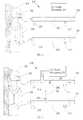
- FIG. 2illustrates the connection of the ventilation apparatus of the present invention to a subject 200 requiring ventilation assistance.
- the ventilation apparatus 100further comprising a first conduit 206 for coupling the ventilation apparatus (e.g., the first vent 104) to the subject's chest or thorax and a second conduit 208 for coupling the ventilation apparatus (e.g., the second vent 106) to the upper airway (e.g., the face and the mouth) of the subject.
- the first conduit 206is coupled to the subject's chest using an enclosure device 204 selected from a body tank system, a chest cuirass, a body wrap, or a combination thereof.
- the enclosure device 204, together with the ventilation apparatusprovide sufficient negative pressure to expand the subject's chest cavity or lungs.
- the second conduit is 208is coupled to the subject's upper airway using a mask 202.
- the mask 202include leak proof mask, oral CPAP mask and the full face mask.
- the mask 202, together with the ventilation apparatus 100provide sufficient positive pressure to open and maintain the subject's upper airway.
- a first pressure sensor 212 and/or a first pressure relief valve 210are disposed in the first conduit 206.
- the first pressure sensor 212is in close proximity to the subject 200.
- a second pressure sensor 216 and/or a second pressure relief valve 214are disposed in the second conduit 208.
- the second pressure sensor 216is in close proximity to the subject 200.
- the first pressure sensor 212 and the second pressure sensor 216are configured to monitor or measure the pressure in the first conduit 206 and the second conduit 208, respectively.
- Non limiting examples of the pressure sensorinclude pressure transducers, pressure transmitters, pressure senders, pressure indicators, piezometers and manometers.
- first 212 and second pressure sensors 216are electronically connected and control the opening and closing of the first pressure relief valve 210 and the second pressure valve 214 respectively, so the pressure within the first conduit 206 and the second conduit 208 are maintained at a predetermined range.
- a gas supply mechanism 218is connected to the second conduit 208.
- the gas from the gas supply mechanism 218(for example, oxygen) is delivered to the second conduit 208 and mixed with the gas from the second space 116 (for example, room air) while the movable spacer 110 rotates in the first direction (D1 as shown in FIG. 1A ).
- the positive pressure generated in the second conduit 208delivers the oxygen from the gas supply mechanism 218 to the upper airway of the patient 200, thereby increase oxygen supply to the subject.
- FIG. 3illustrates another embodiment of the ventilation apparatus 100 of the present invention, wherein the ventilation apparatus 100 further comprising at least one of the following: a third conduit 300 connecting the first conduit 206 and the second conduit 208, a two way pressure relief valve 302 in the second conduit 208 or a one way pressure relief valve 304 in the third conduit 300, wherein the one way pressure relief valve 304 is in close proximity to the first conduit 206.
- the gas supply mechanism 218is proximal to the subject compare to the two way relief valve 302.
- continuous positive pressure in the second conduit 206is contemplated, such as when the subject 200 requires cardiopulmonary resuscitation (CPR) or sputum clearance.
- CPRcardiopulmonary resuscitation
- continue positive pressure in the second conduit 208is achieved as follows: during the inspiratory phase of the breathing cycle, the movable spacer 110 rotates in the first direction (D1) to generate a positive pressure in the second space 116 and second conduit 208. As soon as the movable spacer 110 reaches the stopper 122 prior to or at the second vent 106, the first pressure relief valve 210 in the first conduit 206 opens so the negative pressure generated in the enclosure device 204, the first space 114 and the first conduit 206 during the D1 rotation was equilibrated to atmospheric pressure.
- the second pressure relief valve 214 in the second conduit 208opens so the positive pressure generated in the second space 116 and the second conduit 208 during the D1 rotation was equilibrated to atmospheric pressure.
- positive pressure in the first conduit 206is required, as soon as the pressure in the first conduit 206 is reduced or reaches the atmospheric pressure, detected by the first pressure sensor 212, the first pressure relief valve 210 and the two way pressure relief valve 302 in the second conduit 208 are closed.
- the two way pressure relief valve 302 in the second conduit 208is closed while the first pressure relief valve 210 remains open.
- the second pressure relief valve 214remained open during the D2 rotation/expiration phase.
- the one way pressure relief valve 304opens to allow about 5 to about 50 cm H 2 O of the positive pressure in the first conduit 206 pass through the third conduit 300 to the second conduit 208 and the subject's upper airway.
- the first pressure relief valve 210opens again for gas equilibration so the positive pressure generated in the first space 114 and the first conduit 206 during the D2 rotation/expiration phase was reduced, until the pressure therein reaches the atmospheric pressure.
- the two way pressure relief valve 302 in the second conduit 208opens as the movable spacer 110 reaches the stopper 120 prior to or at the first vent 104.
- the movable spacer 110again rotates in the first direction (D1) to correspond to the subject's inspiration phase, as described in the preceding paragraphs.
- CPR or sputum clearancecan be performed.
- the continuous positive pressure in the second conduit 208maintains the subject's upper airway as well as the continuously supply of a desirable gas (e.g., oxygen) to the subject, while the intermittent positive pressure in the first conduit 206 compresses the subject's chest cavity, to increase cardiac output or expel secretion.
- a desirable gase.g., oxygen
- the frequency of the CPRcan be adjusted by adjusting the speed of the movable spacer 110 rotation.
- the positive pressure(about 5 to about 200 cm H 2 O) is transferred from the first conduit 210 to the third conduit 300 and the second conduit 208 twice with every 30 chest compressions by providing the positive pressure to the enclosure device 204.
- the effect of the movable spacer 110, the first pressure relief valve 210, the second pressure relief valve 214, and the two way valve in the second conduit 302 on the pressure of the first conduit 206 and the second conduit 208is shown in Table 1 and Table 2. Table 1.
- the positive pressure generated by the ventilation apparatus of the present inventionranges from about 0 to about 200 cm H 2 O.
- the lower limit of the positive pressureis equal to or greater than about 10, 11, 12, 13, 14, 15, 16, 17, 18, 19, or 20 cm H 2 O or any value or range of values therebetween in 0.1 cm H 2 O increments (e.g., about 15.2 cm H 2 O, about 12.1 cm H 2 O).
- the upper limit of the positive pressureis equal to or less than about 200, 199, 198, 197, 196, 195, 194, 193, 192, 191, 190 cm H 2 O or any value or range of values therebetween in 0.1 cm H 2 O increments (e.g., about 195.2 cm H 2 O, about 192.1 cm H 2 O).
- the positive pressureis a range of pressure between the lower limit and the upper limit of the positive pressure recite herein, such as 12 cm H 2 O to 200 cm H 2 O, 13.2 cm H 2 O to 199.5 cm H 2 O.
- the negative pressure generated by the ventilation apparatus of the present inventionranges from about 0 to about -200 cm H 2 O.
- the lower limit of the negative pressureis equal to or greater than about -10, -11, -12, -13, -14, -15, -16, -17, -18, -19, or -20 cm H 2 O or any value or range of values therebetween in 0.1 cm H 2 O increments (e.g., about -15.2 cm H 2 O, about -12.1 cm H 2 O).
- the upper limit of the negative pressureis equal to or less than about -200, -199, -198, -197, -196, -195, -194, -193, -192, -191, -190 cm H 2 O or any value or range of values therebetween in 0.1 cm H 2 O increments (e.g., about -196.3 cm H 2 O, about -198.4 cm H 2 O).
- the negative pressureis a range of pressure between the lower limit and the upper limit of the negative pressure recite herein, such as -12 cm H 2 O to -200 cm H 2 O, -13.2 cm H 2 O to -199.5 cm H 2 O.
- PI in the first space114is atmospheric pressure (1033.23 cm H 2 O) and VI is the lung volume of the subject (about 3L).
- the rotation of the movable spacer 110 in the first direction (D1) and in the reverse direction (D2)is one breathing cycle and each breathing cycle takes about 0.5 to about 15 seconds.
- the frequency of each breathing cycleranges from 4 per minutes to 60 per minutes, and can be adjusted according to the subject's age or physical condition.
- the ventilation apparatuscomprises a movable spacer 110 and a second spacer 109 within the casing 102.
- One end of the second spacer 109is fixed to the power mechanism 112.
- the second spacer 109comprises an engagement part 124 and the power mechanism 112 comprises a recess 126.
- the second spacer 109is fixed to the power mechanism 112 by inserting the engagement part 124 into the recess 126 of the power mechanism.
- the movable spacer 110 and the second spacer 109divide the ventilation apparatus into a first space 114 and a second space 116.
- the movable spacer 110moves in the D1 direction (to generate positive pressure in the second vent 106 and negative pressure in the first vent 104) and passes the second vent 106. Just before the movable spacer 110 reaches the second spacer 109, said second spacer 109 will withdraw from the casing 102. In one exemplary embodiment, the second spacer 109 withdraws from the casing by sliding into the placing slot 130 via the transmission shafts 128, as illustrated Fig. 4B . As the second spacer withdraws from the casing 102, the movable spacer 110 continues to move in the D1 direction and reaches the first vent 104. The second spacer 109 is connected to the power mechanism 112 once again so the movable spacer 110 continues to move in the D1 direction to generate negative pressure in the first vent 104 and positive pressure in the second vent 106.
- FIG. 5A and FIG. 5Billustrate a comparative example of a ventilation apparatus 400, comprising a first vent 404, a second vent 406, a casing 402, a movable spacer 410 in operative connection to a guiding device 412.
- the casing 402is substantially tubular.
- the cross section of the casing 402can be substantially circular, substantially oval, or any shape.
- the movable spacer 410is within the casing 402, dividing the casing 402 into a first space 414 and a second space 416.
- the movable spacer 410is substantially rigid. In other embodiments, the movable spacer 410 is substantially flexible.
- the guiding device 412comprises one or more guiding rails 412a to longitudinally slide the movable spacer 410 in D1 or D2 direction.
- the movable spacer 410has an insertion hole 412b for the guiding rail 412a to passes through.
- the guiding rail 412aincludes one or more conveying structures to move the movable spacer 410 in D1 or D2 direction.
- the conveying structureinclude a motor 412c, an inverted tooth chain, or a conveyor belt.
- the pressures in the first space 414 and the second space 416are equal to the atmospheric pressure.
- the gas in the second space 416is compressed and a positive pressure is generated therein to maintain a subject's upper airway.
- the first space 414expands and a negative pressure is generated therein to expand the subject's chest cavity or lung.
- the sliding of the movable spacer 410 in the first (D1) directioncorresponds to the inspiration phase of the subject.
- the first pressure relief valve 210 in the first conduit(as depicted in Fig. 2 ) and the second pressure relief valve 214 in the second conduit (depicted in Fig. 2 ) open simultaneously for gas equilibration. This reduces the negative pressure in the first space 414 and/or first vent 404 and the positive pressure in the second space 416 and/or second vent 406, respectively.
- the pressure in the first space 416 and/or first vent 404reach atmospheric pressure after the opening of the first pressure relief valve 210.
- the pressure in the first space 414 and/or the first vent 404is measured by a pressure sensor 404A.
- the pressure in the second space 416 and/or second vent 406reach atmospheric pressure after the opening of the second pressure relief valve 214. This is followed by the rotation of the movable spacer 410 in reverse of the first direction (in D2 direction, from the second space 416 to the first space 414), as shown in FIG. 5B .
- the first pressure relief valve 212 and the second pressure relief valve 214remain open so the pressure in the first space 414, the first vent 404, the second space 416 and/or second vent 406 during the D2 sliding remains as atmospheric pressure.
- the sliding of the movable spacer 410 in D2 directioncorresponds to the expiration phase of the subject.
- the pressure sensor 404A and pressure sensor 406Aare in communication with the movable spacer 410. According to the input from pressure sensors 404A and 406A, the pressure in the first space 414 and/or the first vent 404 as well as the pressure in the second space 416 and/or the second vent 406 can be adjusted by altering the rotation of the movable spacer 410.
- the ventilation apparatus described hereinpresent, amongst others, the following features:
Landscapes
- Health & Medical Sciences (AREA)
- Engineering & Computer Science (AREA)
- Pulmonology (AREA)
- General Health & Medical Sciences (AREA)
- Emergency Medicine (AREA)
- Veterinary Medicine (AREA)
- Heart & Thoracic Surgery (AREA)
- Public Health (AREA)
- Life Sciences & Earth Sciences (AREA)
- Animal Behavior & Ethology (AREA)
- Biomedical Technology (AREA)
- Hematology (AREA)
- Anesthesiology (AREA)
- Mechanical Engineering (AREA)
- General Engineering & Computer Science (AREA)
- Cardiology (AREA)
- Epidemiology (AREA)
- Pain & Pain Management (AREA)
- Physical Education & Sports Medicine (AREA)
- Rehabilitation Therapy (AREA)
- Percussion Or Vibration Massage (AREA)
- External Artificial Organs (AREA)
- Measurement Of The Respiration, Hearing Ability, Form, And Blood Characteristics Of Living Organisms (AREA)
Description
- The present invention relates to a ventilation apparatus for ventilating a subject, by synchronously deliver a positive pressure ventilation and a negative pressure ventilation to a subject in need thereof using the ventilation apparatus described herein.
- Mechanical ventilation refers to methods to mechanically assist a patient's breathing and/or replace the patient's spontaneous breathing, using a ventilator or a compression bag. Mechanical ventilation delivers two types of ventilation: (a) positive pressure ventilation, whereby air (or a gas mix) is pushed into the patient's upper airway and lung, and (b) negative pressure ventilation, whereby the patient's chest cavity expands to create sub-atmospheric pressure within the patient's lungs. The patient's lungs naturally recoil and expel the gas within in the absence of negative pressure ventilation.
- Ventilators for patients requiring breathing assistance have traditionally been large, heavy, power-hungry devices that have provided little, if any mobility to a patient. Positive pressure ventilation alone is uncomfortable for the patient, cannot be used to clear the airway secretion and pushes air into less resistant lung space, which can lead to ventilation/perfusion mismatch. Negative pressure ventilation alone may cause upper airway collapse and compromises patient's airway. The use of two independent ventilators (a positive pressure ventilator generating positive pressure ventilation and a negative pressure ventilator generating negative pressure ventilation) to provide synchronized ventilation has shown limitations in efficacy and safety. For example, the positive pressure ventilator and the negative pressure ventilator may dyssynchronize over time. The inability of two separate ventilators to synchronously deliver and match the patient's flow demand can lead to serious complications, such as hypoxia, barotrauma, and prolonged mechanical ventilation time.
US 2,699,163 discloses a respiratory comprising one or two compressors, each compressor is cylindrical with a piston dividing the compressor into a two chambers to provide alternative positive and negative pressure ventilations.US 5,086,767 teaches a ventilator to provide low pressure air during inhalation and remains stationary during exhalation. - There is an unmet need to develop a ventilator to synchronously deliver a positive pressure ventilation and a negative pressure ventilation to patients with respiratory distress or requiring pulmonary rehabilitation. The present invention provides ventilators to satisfy these and other needs.
- It is an object of the invention to provide a ventilation apparatus, comprising a casing with a first vent and a second vent; a fixed spacer disposed within the casing; and a movable spacer in operative connection with a power mechanism, wherein the movable spacer and the fixed spacer divide the casing into a first space and a second space, wherein the first vent and the second vent are positioned on each side of the fixed spacer, and wherein the movable spacer rotate in a first direction and simultaneously generate a negative pressure in the first vent and a positive pressure in the second vent, and the movable spacer rotate in a reverse of the first direction and simultaneously reduce the negative pressure in the first vent and reduce the positive pressure in the second vent, wherein the ventilation apparatus further comprises a first conduit for coupling the first vent to the chest of a subject and a second conduit for coupling the second vent to the upper airway of the subject.
- In a comparative example a ventilation apparatus is provided comprising a casing with a first vent and a second vent; a movable spacer in operative connection with a guiding device, wherein the movable spacer divide the casing into a first space and a second space, wherein the first vent and the second vent are positioned on each side of the movable spacer, and wherein the movable spacer moves in a first direction and simultaneously generate a negative pressure in the first vent and a positive pressure in the second vent, and the movable spacer moves in reverse of the first direction and simultaneously reduce the negative pressure in the first vent and reduce the positive pressure in the second vent.
- Advantageously, the first conduit further comprises a pressure relief valve, a pressure sensor or a combination thereof; and/or the second conduit further comprises a gas supply mechanism, a pressure sensor, at least one pressure relief valve or a combination thereof.
- In an embodiment, the ventilation apparatus further comprises a third conduit for coupling the first conduit to the second conduit, wherein the third conduit comprises an one way valve. Advantageously, the one way valve allows the pressure flow from the first conduit to the second conduit. Alternatively, the one way valve does not allow the pressure flow from the first conduit to the second conduit.
- In an embodiment, the negative pressure is about 0 to -200 cm H2O, and/or the positive pressure is about 0 to 200 cm H2O.
- In an embodiment, the volume of the first space or the second space is about 0.5 L to about 20 L.
- Advantageously, the ventilation apparatus is substantially free of a controller to synchronize the delivery of a positive pressure and a negative pressure ventilation.
- The present disclosure further deals with methods for ventilating a subject, comprising synchronize generating a positive pressure ventilation and a negative pressure ventilation using the ventilation apparatus described herein and delivering the negative pressure ventilation, the positive pressure ventilation or synchronize delivering the negative pressure and the positive pressure ventilation to the subject during the inhalation phase of the subject, are also provided.
- In an example, the method of ventilating a subject, comprises the steps of:
- synchronize generating a positive pressure ventilation and a negative pressure ventilation using a ventilation apparatus as disclosed above; and
- delivering the negative pressure ventilation, the positive pressure ventilation or synchronize delivering the negative pressure and the positive pressure ventilation to the subject during the inhalation phase of the subject
- In an embodiment, the ventilation apparatus as used comprises a first conduit for coupling the apparatus to the chest of the subject, a second conduit for coupling the ventilation apparatus to the upper airway of a subject, and a third conduit for coupling the first conduit and the second conduit, wherein the third conduit comprises an one way valve. Advantageously, the one way valve allows about 0 to 50 cm H2O of positive pressure flow from the first conduit to the second conduit during the exhalation phase of the subject.
- In an example, the method further comprises the step of delivering a positive pressure ventilation about 5 to 50 cm H2O to the upper airway of the subject during the exhalation phase of the subject. Advantageously, the negative pressure is about 0 to -200 cm H2O and/or wherein the positive pressure is about 0 to 200 cm H2O.
- In an embodiment, the delivering of the positive pressure ventilation, the negative pressure ventilation or synchronize delivering the negative pressure and the positive pressure ventilation takes about 0.5 to about 15 seconds.
- The present invention is defined by the appended claims.
- Illustrative embodiments of the present invention are described in detail below with reference to
figures 1 to 4 . FIGS. 1A and1B are top angle views of theventilation apparatus 100 according to one embodiment of the present invention.FIG. 2 illustrates schematically the connection of the first conduit and the second conduit of theventilation apparatus 100 to a subject.FIG. 3 illustrates schematically the connection of the first conduit, the second conduit and the third conduit of theventilation apparatus 100 to a subject.FIG. 4A and FIG.4B are top angle views of theventilation apparatus 100 according to the second embodiment of the present invention.FIG. 5A and FIG. 5B are the horizontal cross section views of theventilation apparatus 100 according to a comparative example.- Hereinafter, embodiments of the present disclosure will be described in detail with reference to the accompanying drawings so that those skilled in the art to which the present disclosure pertains can realize the present disclosure. As those skilled in the art would realize, the described embodiments may be modified in various different ways.
- As used herein, the singular forms "a", "an" and "the" are intended to include the plural forms as well, unless the context clearly indicates otherwise. It will be further understood that the terms "comprises" and/or "comprising," when used in this specification, specify the presence of stated features, integers, steps, operations, elements, and/or components, but do not preclude the presence or addition of one or more other features, integers, steps, operations, elements, components, and/or groups thereof. It will be further understood that although the terms first and second are used herein to describe various elements, these elements should not be limited by these terms. These terms are only used to distinguish one element from another element.
- For clarity and conciseness of the description, parts may be omitted from the drawings, and same reference characters or numerals may indicate identical parts or analogous parts. In the drawings, thicknesses of layers, films, panels, regions, etc., may be exaggerated for clarity and may not limit embodiments of the invention. If an element such as a layer, film, region, or substrate is referred to as being "on" another element, it can be directly on the other element, or an intervening element may be present.
- The term "subject" can refer to a vertebrate who is in respiratory distress or in need of ventilation support. Subjects include warm-blooded animals, such as mammals, such as a primate, and, more preferably, a human. Non-human primates are subjects as well. The term subject includes domesticated animals, such as cats, dogs, etc., livestock (for example, cattle, horses, pigs, sheep, goats, etc.) and laboratory animals (for example, mouse, rabbit, rat, gerbil, guinea pig, etc.). Thus, veterinary uses and medical formulations are contemplated herein.
- All numbers herein may be understood as modified by "about." In one embodiment, the term "about," when referring to a measurable value such as an amount, a temporal duration, and the like, is meant to encompass variations of ± 10%, preferably ± 5%, more preferably ± 1%, and even more preferably ± 0.1% from the specified value, as such variations are appropriate to the negative pressure, unless other specified. As used herein, the term "about," when referring to a range, is meant to encompass variations of ± 10% within the difference of the range, preferably ± 5%, more preferably ± 1%, and even more preferably ±0.1% from the specified value, as such variations are appropriate to the negative pressure, unless other specified.
- The present invention relates to a portable or
wearable ventilation apparatus 100 to provide synchronized positive pressure and negative pressure ventilation to a subject, without a controller to synchronize the delivery of the positive and negative pressure ventilation. In one embodiment, as shown inFIG. 1A andFIG. 1B , theventilation apparatus 100 comprises acasing 102 with afirst vent 104 and asecond vent 106, a fixedspacer 108, amovable spacer 110 coupled to apower mechanism 112. In some embodiments, thecasing 102 is substantially circular. The fixedspacer 108 is disposed within thecasing 102, and together with themovable spacer 110, to divide thecasing 102 into afirst space 114 and asecond space 116. There is no communication between the gas in thefirst space 114 and the second space 116 (i.e., the gas in thefirst space 114 does not move to thesecond space 116 and vice versa). In some embodiments, the fixedspacer 108 and themovable spacer 110 are rigid. In other embodiments, the fixedspacer 108 and themovable spacer 110 are flexible. - In one embodiment, the
power mechanism 112 comprises at least one of the following: a gear set, an electric motor, or an adjustable speed drive for adjusting the speed of the electric motor. In another embodiment, one end of themovable spacer 110 may be coupled to the gear set and served as an axis, such that themovable spacer 110 is able to be rotated by thepower mechanism 112 around the axis. - Referring to
FIG. 1A , prior to themovable spacer 110 moving in the first (D1) direction, the pressure in thefirst space 114 and in thesecond space 116 may be the same as the atmospheric pressure. Based on Boyle's law, as themovable spacer 110 rotates in the first (D1) direction (i.e., from thefirst space 114 toward the second space 116), the gas in thesecond space 116 is compressed and a positive pressure is generated therein to maintain a subject's upper airway. At the same time, thefirst space 114 expands and a negative pressure is generated therein to expand the subject's chest cavity or lung. In one embodiment, the rotation of themovable spacer 110 in the first (D1) direction corresponds to the inspiration phase of the subject. - In one embodiment, as the
movable spacer 110 reaches astopper 122 prior to or at thesecond vent 106, the firstpressure relief valve 210 in the first conduit (depicted inFig. 2 ) and the secondpressure relief valve 214 in the second conduit (depicted inFig. 2 ) open simultaneously for gas equilibration. This reduces the negative pressure in thefirst space 114 and/orfirst vent 104 and the positive pressure in thesecond space 116 and/orsecond vent 106, respectively. In one embodiment, the pressure in thefirst space 116 and/orfirst vent 104 reach atmospheric pressure after the opening of the firstpressure relief valve 210. In an exemplary embodiment, the pressure in thefirst space 114 and/or thefirst vent 104 is measured by apressure sensor 104A. In another embodiment, the pressure in thesecond space 116 and/orsecond vent 106 reach atmospheric pressure after the opening of the secondpressure relief valve 214. This is followed by the rotation of themovable spacer 110 in reverse of the first direction (in D2 direction, from thesecond space 116 to the first space 114), as shown inFIG. 1B . In other embodiments, as the movable spacer rotates in D2 direction, the firstpressure relief valve 212 and the secondpressure relief valve 214 remain open so the pressure in thefirst space 114, thefirst vent 104, thesecond space 116 and/orsecond vent 106 during the D2 rotation remains at atmospheric pressure. In one embodiment, the rotation of themovable spacer 110 in reverse of the first (D1) direction (i.e., moving in D2 direction) corresponds to the expiration phase of the subject. In an exemplary embodiment, the pressure in thesecond space 116 and/or thesecond vent 106 is measured by apressure sensor 106A. In another exemplary embodiment, thepressure sensor 104A andpressure sensor 106A are in communication with themovable spacer 110. According to the input frompressure sensors first space 114 and/or thefirst vent 104 as well as the pressure in thesecond space 116 and/or thesecond vent 106 can be adjusted by altering the rotation of themovable spacer 110. FIG. 2 illustrates the connection of the ventilation apparatus of the present invention to a subject 200 requiring ventilation assistance. Theventilation apparatus 100 further comprising afirst conduit 206 for coupling the ventilation apparatus (e.g., the first vent 104) to the subject's chest or thorax and asecond conduit 208 for coupling the ventilation apparatus (e.g., the second vent 106) to the upper airway (e.g., the face and the mouth) of the subject. In one embodiment, thefirst conduit 206 is coupled to the subject's chest using anenclosure device 204 selected from a body tank system, a chest cuirass, a body wrap, or a combination thereof. In an exemplary embodiment, theenclosure device 204, together with the ventilation apparatus provide sufficient negative pressure to expand the subject's chest cavity or lungs. In one embodiment, the second conduit is 208 is coupled to the subject's upper airway using amask 202. Non limiting examples of themask 202 include leak proof mask, oral CPAP mask and the full face mask. In an exemplary embodiment, themask 202, together with theventilation apparatus 100 provide sufficient positive pressure to open and maintain the subject's upper airway.- In some embodiments, a
first pressure sensor 212 and/or a firstpressure relief valve 210 are disposed in thefirst conduit 206. In an exemplary embodiment, thefirst pressure sensor 212 is in close proximity to the subject 200. In other embodiments, asecond pressure sensor 216 and/or a secondpressure relief valve 214 are disposed in thesecond conduit 208. In an exemplary embodiment, thesecond pressure sensor 216 is in close proximity to the subject 200. Thefirst pressure sensor 212 and thesecond pressure sensor 216 are configured to monitor or measure the pressure in thefirst conduit 206 and thesecond conduit 208, respectively. Non limiting examples of the pressure sensor include pressure transducers, pressure transmitters, pressure senders, pressure indicators, piezometers and manometers. In some embodiments, the first 212 andsecond pressure sensors 216 are electronically connected and control the opening and closing of the firstpressure relief valve 210 and thesecond pressure valve 214 respectively, so the pressure within thefirst conduit 206 and thesecond conduit 208 are maintained at a predetermined range. - In some embodiments, a
gas supply mechanism 218 is connected to thesecond conduit 208. The gas from the gas supply mechanism 218 (for example, oxygen) is delivered to thesecond conduit 208 and mixed with the gas from the second space 116 (for example, room air) while themovable spacer 110 rotates in the first direction (D1 as shown inFIG. 1A ). In other embodiment, the positive pressure generated in thesecond conduit 208 delivers the oxygen from thegas supply mechanism 218 to the upper airway of thepatient 200, thereby increase oxygen supply to the subject. FIG. 3 illustrates another embodiment of theventilation apparatus 100 of the present invention, wherein theventilation apparatus 100 further comprising at least one of the following: athird conduit 300 connecting thefirst conduit 206 and thesecond conduit 208, a two waypressure relief valve 302 in thesecond conduit 208 or a one waypressure relief valve 304 in thethird conduit 300, wherein the one waypressure relief valve 304 is in close proximity to thefirst conduit 206. In an exemplary embodiment, thegas supply mechanism 218 is proximal to the subject compare to the twoway relief valve 302.- In certain embodiments, continuous positive pressure in the
second conduit 206 is contemplated, such as when the subject 200 requires cardiopulmonary resuscitation (CPR) or sputum clearance. In an exemplary embodiment, continue positive pressure in thesecond conduit 208 is achieved as follows: during the inspiratory phase of the breathing cycle, themovable spacer 110 rotates in the first direction (D1) to generate a positive pressure in thesecond space 116 andsecond conduit 208. As soon as themovable spacer 110 reaches thestopper 122 prior to or at thesecond vent 106, the firstpressure relief valve 210 in thefirst conduit 206 opens so the negative pressure generated in theenclosure device 204, thefirst space 114 and thefirst conduit 206 during the D1 rotation was equilibrated to atmospheric pressure. Similarly, the secondpressure relief valve 214 in thesecond conduit 208 opens so the positive pressure generated in thesecond space 116 and thesecond conduit 208 during the D1 rotation was equilibrated to atmospheric pressure. In one embodiment, in which positive pressure in thefirst conduit 206 is required, as soon as the pressure in thefirst conduit 206 is reduced or reaches the atmospheric pressure, detected by thefirst pressure sensor 212, the firstpressure relief valve 210 and the two waypressure relief valve 302 in thesecond conduit 208 are closed. In another embodiment, in which positive pressure in thefirst conduit 206 is not required, as soon as the pressure in thesecond conduit 208 is reduced or reaches the atmospheric pressure, detected by thesecond pressure sensor 216, the two waypressure relief valve 302 in thesecond conduit 208 is closed while the firstpressure relief valve 210 remains open. In some embodiments, the secondpressure relief valve 214 remained open during the D2 rotation/expiration phase. As themovable spacer 110 rotates in D2 direction, the pressure in thefirst space 114 and thefirst conduit 206 increases to a point wherein the pressure in the first conduit 206 (detected by the first pressure sensor 212) is higher than that in the second conduit 208 (detected by the second pressure sensor 216), the one waypressure relief valve 304 opens to allow about 5 to about 50 cm H2O of the positive pressure in thefirst conduit 206 pass through thethird conduit 300 to thesecond conduit 208 and the subject's upper airway. As themovable spacer 110 reaches thestopper 120 prior to or at thefirst vent 104, the firstpressure relief valve 210 opens again for gas equilibration so the positive pressure generated in thefirst space 114 and thefirst conduit 206 during the D2 rotation/expiration phase was reduced, until the pressure therein reaches the atmospheric pressure. In one embodiment, the two waypressure relief valve 302 in thesecond conduit 208 opens as themovable spacer 110 reaches thestopper 120 prior to or at thefirst vent 104. Themovable spacer 110 again rotates in the first direction (D1) to correspond to the subject's inspiration phase, as described in the preceding paragraphs. - By rotating the
movable spacer 110 in a first (D1) direction and in reverse (D2) to the first direction described herein, in combination with athird conduit 300 to continuously provide about 5 to about 200 cm H2O to thesecond conduit 208, CPR or sputum clearance can be performed. In one embodiment, the continuous positive pressure in thesecond conduit 208 maintains the subject's upper airway as well as the continuously supply of a desirable gas (e.g., oxygen) to the subject, while the intermittent positive pressure in thefirst conduit 206 compresses the subject's chest cavity, to increase cardiac output or expel secretion. The continuous positive pressure in thesecond conduit 208 and in the upper airway of the subject is an advantage compare to the manual CPR, which provides intermittent positive pressure to the subject's upper airway. - The frequency of the CPR can be adjusted by adjusting the speed of the
movable spacer 110 rotation. In one embodiment, during advance cardiac life support, the positive pressure (about 5 to about 200 cm H2O) is transferred from thefirst conduit 210 to thethird conduit 300 and thesecond conduit 208 twice with every 30 chest compressions by providing the positive pressure to theenclosure device 204. - In one embodiment, the effect of the
movable spacer 110, the firstpressure relief valve 210, the secondpressure relief valve 214, and the two way valve in thesecond conduit 302 on the pressure of thefirst conduit 206 and thesecond conduit 208 is shown in Table 1 and Table 2.Table 1. The effect of the movable spacer, the pressure relief valves on the pressure in first conduit and second conduit during synchronized pressured ventilation Subject's breathing Cycle Movable spacer 110Pressure in 1st conduit Pressure in 2nd conduit 1st pressure relief valve 2102nd pressure relief valve 214Valve in 2nd conduit 302Inspiration Starts at the stopper 120 in the first ventAtmospheric pressure Atmospheric pressure X X ○ Ends at the stopper 122 in the second ventMaximum negative pressure Maximum positive pressure X X ○ Expiration At the stopper 122 in the second ventAtmospheric/ a lowered negative pressure Atmospheric / a lowered positive pressure ○ ○ ○ Expiration Starts at the stopper 122 in the second ventAtmospheric / a lowered negative pressure Atmospheric / a lowered positive pressure ○ ○ ○ Ends at the stopper 120 in the first ventAtmospheric pressure Atmospheric pressure ○ ○ ○ X indicates the valve is closed
○ indicates the valve is openedTable 2. The effect of the movable spacer, the pressure relief valves on the pressure in first conduit, second conduit and third conduit. Subject's breathing Cycle Movable spacer 110Pressure in 1st conduit Pressure in 2nd conduit 1st pressure relief valve 2102nd pressure relief valve 214Valve in 2nd conduit 302Expiration phase At the stopper 122 in the second ventAtmospheric pressure Atmospheric pressure/ pre-set pressure * ○ ○ X Move towards the stopper 120 in the first ventIncreasing positive pressure Atmospheric pressure/ pre-set pressure * X ○ X At the stopper 120 in the first ventMaximum positive pressure Atmospheric pressure/ pre-set pressure * X ○ X Inspiration phase At the stopper 120 in the first ventAtmospheric pressure Atmospheric pressure/ pre-set pressure * ○ ○ ○ Move towards the stopper 122 in the second ventIncreasing Negative pressure/ atmospheric pressure Increasing positive pressure/ pre-set pressure * X/○ X ○ At the stopper 122 in the second ventMaximum negative pressure/ atmospheric pressure Maximum positive pressure/ pre-set pressure * X/○ X ○ X indicates the valve is closed
○ indicates the valve is opened
* pre-set pressure is about 5, 6, 7, 8, 9, 10 cm H2O or any range of value therebetween - In one embodiment, the positive pressure generated by the ventilation apparatus of the present invention ranges from about 0 to about 200 cm H2O. In an exemplary embodiment, the lower limit of the positive pressure is equal to or greater than about 10, 11, 12, 13, 14, 15, 16, 17, 18, 19, or 20 cm H2O or any value or range of values therebetween in 0.1 cm H2O increments (e.g., about 15.2 cm H2O, about 12.1 cm H2O). In another exemplary embodiment, the upper limit of the positive pressure is equal to or less than about 200, 199, 198, 197, 196, 195, 194, 193, 192, 191, 190 cm H2O or any value or range of values therebetween in 0.1 cm H2O increments (e.g., about 195.2 cm H2O, about 192.1 cm H2O). In another embodiment, the positive pressure is a range of pressure between the lower limit and the upper limit of the positive pressure recite herein, such as 12 cm H2O to 200 cm H2O, 13.2 cm H2O to 199.5 cm H2O.
- In some embodiments, the negative pressure generated by the ventilation apparatus of the present invention ranges from about 0 to about -200 cm H2O. In an exemplary embodiment, the lower limit of the negative pressure is equal to or greater than about -10, -11, -12, -13, -14, -15, -16, -17, -18, -19, or -20 cm H2O or any value or range of values therebetween in 0.1 cm H2O increments (e.g., about -15.2 cm H2O, about -12.1 cm H2O). In another exemplary embodiment, the upper limit of the negative pressure is equal to or less than about -200, -199, -198, -197, -196, -195, -194, -193, -192, -191, -190 cm H2O or any value or range of values therebetween in 0.1 cm H2O increments (e.g., about -196.3 cm H2O, about -198.4 cm H2O). In another embodiment, the negative pressure is a range of pressure between the lower limit and the upper limit of the negative pressure recite herein, such as -12 cm H2O to -200 cm H2O, -13.2 cm H2O to -199.5 cm H2O.
- In other embodiments, the negative pressure and the positive pressure of the
ventilation apparatus 100 can be calculated according to the Boyle's equation P1∗V1 = P2∗V2. In one exemplary embodiment, before themovable spacer 110 moves in the first direction (D1), PI in the first space114 is atmospheric pressure (1033.23 cm H2O) and VI is the lung volume of the subject (about 3L). As themovable spacer 110 rotates in the first direction until it reaches the stopper at the second vent, V2 = 3 L(lung capacity of the subject) + 3 L(volume of the enclosure device 204)= 6 L and the calculated P2 =P1∗V1/V2=501.67 cm H2O. Hence, the maximum negative pressure Pnm=P2-atmospheric pressure=-501.67 cmH2O. In another exemplary embodiment, before themovable spacer 110 moves in the D2 direction (i.e., the reverse of the first direction), P1' is atmospheric pressure (1033.23 cmH2O) and VI' =3 L (volume of the enclosure device 204) + 3 L (the lung capacity of the patient) = 6 L. As themovable spacer 110 rotates in reverse of the first direction until it reaches the stopper at the first vent, V2' is the lung volume =3L and the calculated positive pressure P2'=P1'∗V1'/V2'=2066 cm H2O. Hence, the maximum positive pressure Ppm=P2'-atmospheric pressure=2066-1033 cmH2O =1033 cmH2O. - In one embodiment, the rotation of the
movable spacer 110 in the first direction (D1) and in the reverse direction (D2) is one breathing cycle and each breathing cycle takes about 0.5 to about 15 seconds. The frequency of each breathing cycle ranges from 4 per minutes to 60 per minutes, and can be adjusted according to the subject's age or physical condition. - In another embodiment, referring to
FIG. 4A , the ventilation apparatus comprises amovable spacer 110 and asecond spacer 109 within thecasing 102. One end of thesecond spacer 109 is fixed to thepower mechanism 112. In one exemplary embodiment, thesecond spacer 109 comprises anengagement part 124 and thepower mechanism 112 comprises arecess 126. Thesecond spacer 109 is fixed to thepower mechanism 112 by inserting theengagement part 124 into therecess 126 of the power mechanism. Themovable spacer 110 and thesecond spacer 109 divide the ventilation apparatus into afirst space 114 and asecond space 116. - In one embodiment, the
movable spacer 110 moves in the D1 direction (to generate positive pressure in thesecond vent 106 and negative pressure in the first vent 104) and passes thesecond vent 106. Just before themovable spacer 110 reaches thesecond spacer 109, saidsecond spacer 109 will withdraw from thecasing 102. In one exemplary embodiment, thesecond spacer 109 withdraws from the casing by sliding into the placingslot 130 via thetransmission shafts 128, as illustratedFig. 4B . As the second spacer withdraws from thecasing 102, themovable spacer 110 continues to move in the D1 direction and reaches thefirst vent 104. Thesecond spacer 109 is connected to thepower mechanism 112 once again so themovable spacer 110 continues to move in the D1 direction to generate negative pressure in thefirst vent 104 and positive pressure in thesecond vent 106. FIG. 5A and FIG. 5B illustrate a comparative example of aventilation apparatus 400, comprising afirst vent 404, asecond vent 406, acasing 402, amovable spacer 410 in operative connection to aguiding device 412. In an exemplary embodiment, thecasing 402 is substantially tubular. The cross section of thecasing 402 can be substantially circular, substantially oval, or any shape. Themovable spacer 410 is within thecasing 402, dividing thecasing 402 into afirst space 414 and asecond space 416.- There is no communication between the gas in the
first space 414 and the second space 416 (i.e., the gas in thefirst space 414 does not move to thesecond space 416 and vice versa). In some embodiments, themovable spacer 410 is substantially rigid. In other embodiments, themovable spacer 410 is substantially flexible. - In some embodiments, the guiding
device 412 comprises one ormore guiding rails 412a to longitudinally slide themovable spacer 410 in D1 or D2 direction. In a preferred embodiment, themovable spacer 410 has aninsertion hole 412b for the guidingrail 412a to passes through. The guidingrail 412a includes one or more conveying structures to move themovable spacer 410 in D1 or D2 direction. Non limiting examples of the conveying structure include amotor 412c, an inverted tooth chain, or a conveyor belt. - Prior to the movable spacer move in D1 direction, the pressures in the
first space 414 and thesecond space 416 are equal to the atmospheric pressure. When the movable spacer moves in D1 direction (i.e., from thefirst space 414 toward the second space 416), the gas in thesecond space 416 is compressed and a positive pressure is generated therein to maintain a subject's upper airway. At the same time, thefirst space 414 expands and a negative pressure is generated therein to expand the subject's chest cavity or lung. In one embodiment, the sliding of themovable spacer 410 in the first (D1) direction corresponds to the inspiration phase of the subject. - In one embodiment, as the
movable spacer 410 reaches thesecond vent 406 or astopper 422, the firstpressure relief valve 210 in the first conduit (as depicted inFig. 2 ) and the secondpressure relief valve 214 in the second conduit (depicted inFig. 2 ) open simultaneously for gas equilibration. This reduces the negative pressure in thefirst space 414 and/orfirst vent 404 and the positive pressure in thesecond space 416 and/orsecond vent 406, respectively. - In one embodiment, the pressure in the
first space 416 and/orfirst vent 404 reach atmospheric pressure after the opening of the firstpressure relief valve 210. In an exemplary embodiment, the pressure in thefirst space 414 and/or thefirst vent 404 is measured by apressure sensor 404A. In another embodiment, the pressure in thesecond space 416 and/orsecond vent 406 reach atmospheric pressure after the opening of the secondpressure relief valve 214. This is followed by the rotation of themovable spacer 410 in reverse of the first direction (in D2 direction, from thesecond space 416 to the first space 414), as shown inFIG. 5B . - In other embodiments, as the movable spacer slides in D2 direction, the first
pressure relief valve 212 and the secondpressure relief valve 214 remain open so the pressure in thefirst space 414, thefirst vent 404, thesecond space 416 and/orsecond vent 406 during the D2 sliding remains as atmospheric pressure. In one embodiment, the sliding of themovable spacer 410 in D2 direction corresponds to the expiration phase of the subject. - In another exemplary embodiment, the
pressure sensor 404A andpressure sensor 406A are in communication with themovable spacer 410. According to the input frompressure sensors first space 414 and/or thefirst vent 404 as well as the pressure in thesecond space 416 and/or thesecond vent 406 can be adjusted by altering the rotation of themovable spacer 410. - The ventilation apparatus described herein present, amongst others, the following features:
- 1. Synchronously deliver a positive pressure ventilation and a negative pressure ventilation to a subject without any time lag;
- 2. A small casing and a simple power mechanism are required, making the device portable and affordable; and
- 3. An optional third conduit can be used to perform CPR, by synchronously providing positive pressure in the first conduit and the second conduit.
- While the disclosure has been described by way of example and in terms of the preferred embodiment(s), it is to be understood that the disclosure is not limited thereto. On the contrary, it is intended to cover various modifications and similar arrangements and procedures, and the scope of the appended claims therefore should be accorded the broadest interpretation so as to encompass all such modifications and similar arrangements and procedures.
Claims (7)
- A ventilation apparatus (100), comprising:a casing (102) with a first vent (104) and a second vent (106);a fixed spacer (108) disposed within the casing; anda movable spacer (110) in operative connection with a power mechanism (112),wherein the movable spacer and the fixed spacer divide the casing into a first space (114) and a second space (116),wherein the first vent and the second vent are positioned on each side of the fixed spacer, andwherein the movable spacer rotate in a first direction (D1) and simultaneously generate a negative pressure in the first vent and a positive pressure in the second vent, and the movable spacer rotate in reverse (D2) of the first direction and simultaneously reduce the negative pressure in the first vent and reduce the positive pressure in the second vent,characterized in thatit comprises a first conduit (206) for coupling the first vent to the chest of a subject (200) anda second conduit (208) for coupling the second vent to the upper airway of the subject.
- The ventilation apparatus of claim 1 , comprising at least one of the following:(a) the first conduit further comprising a pressure relief valve (210), a pressure sensor (212) or a combination thereof; or(b) the second conduit further comprising a gas supply mechanism (218), a pressure sensor (216), at least one pressure relief valve (214) or a combination thereof.
- The ventilation apparatus of claim 1 or 2, further comprising a third conduit (300) for coupling the first conduit to second conduit, wherein the third conduit comprises an one way valve (304).
- The ventilation apparatus of claim 3, wherein the one way valve allows the pressure flow from the first conduit to the second conduit.
- The ventilation apparatus of anyone of claims 1 to 4, wherein the negative pressure is about 0 to -200 cm H2O and/or wherein the positive pressure is about 0 to 200 cm H2O.
- The ventilation of apparatus of anyone of claims 1 to 5, wherein the volume of the first space (114) and/or the volume of the second space (116) is about 0.5 L to about 20 L.
- The ventilation apparatus of anyone of claims 1 to 6, wherein the ventilation apparatus is substantially free of a controller to synchronize the delivery of a positive pressure and a negative pressure ventilation.
Applications Claiming Priority (1)
| Application Number | Priority Date | Filing Date | Title |
|---|---|---|---|
| US201662339211P | 2016-05-20 | 2016-05-20 |
Publications (2)
| Publication Number | Publication Date |
|---|---|
| EP3246062A1 EP3246062A1 (en) | 2017-11-22 |
| EP3246062B1true EP3246062B1 (en) | 2020-11-25 |
Family
ID=58772385
Family Applications (1)
| Application Number | Title | Priority Date | Filing Date |
|---|---|---|---|
| EP17171942.0ANot-in-forceEP3246062B1 (en) | 2016-05-20 | 2017-05-19 | Ventilation apparatus |
Country Status (4)
| Country | Link |
|---|---|
| US (1) | US10792459B2 (en) |
| EP (1) | EP3246062B1 (en) |
| CN (1) | CN107648711B (en) |
| TW (2) | TWM544941U (en) |
Cited By (1)
| Publication number | Priority date | Publication date | Assignee | Title |
|---|---|---|---|---|
| DE202020102459U1 (en) | 2020-04-30 | 2021-08-02 | Richard Brink Gmbh & Co. Kg | Ventilator |
Families Citing this family (3)
| Publication number | Priority date | Publication date | Assignee | Title |
|---|---|---|---|---|
| WO2020056511A1 (en)* | 2018-09-19 | 2020-03-26 | St. Michael's Hospital | Systems, devices and methods for modulating a respiratory drive of a patient |
| CN109847121B (en)* | 2019-04-04 | 2021-05-04 | 李雷 | Quick aspirator for first aid |
| FR3124954A1 (en)* | 2021-07-08 | 2023-01-13 | Université De Lorraine | Compact respirator |
Family Cites Families (22)
| Publication number | Priority date | Publication date | Assignee | Title |
|---|---|---|---|---|
| US2699163A (en)* | 1950-06-26 | 1955-01-11 | Carl-Gunnar D Engstrom | Respirator |
| US3533398A (en)* | 1968-06-21 | 1970-10-13 | William C Jones | Pulmonary monitoring apparatus |
| US5086767A (en)* | 1990-09-26 | 1992-02-11 | Canadian Aging & Rehabilitation Product Development Corporation | Ventilator for assisting the breathing of a patient |
| US5542415A (en)* | 1991-05-07 | 1996-08-06 | Infrasonics, Inc. | Apparatus and process for controlling the ventilation of the lungs of a patient |
| CN2133309Y (en)* | 1992-06-13 | 1993-05-19 | 北京市海淀区众大机电新技术研究所 | Negative pressure pulsating lung-treating instrument |
| CN2250157Y (en)* | 1996-04-01 | 1997-03-26 | 王年云 | Motor multiple sucker external positive and negative pressure respirator |
| US7766011B2 (en)* | 2003-04-28 | 2010-08-03 | Advanced Circulatory Systems, Inc. | Positive pressure systems and methods for increasing blood pressure and circulation |
| US6860265B1 (en)* | 2003-09-08 | 2005-03-01 | J.H. Emerson Company | Insufflation-exsufflation system for removal of broncho-pulmonary secretions with automatic triggering of inhalation phase |
| EP2023882A1 (en) | 2006-05-12 | 2009-02-18 | Andrea Fiorina | A portable-personal device for pulmonary ventilation and resuscitation at negative and positive intermittent pressures |
| CN200960346Y (en)* | 2006-10-13 | 2007-10-17 | 赵子文 | Non-invasive positive and negative pressure breathing assistance device |
| EP2464404B1 (en) | 2009-08-11 | 2017-06-28 | ResMed Motor Technologies Inc. | Single stage, axial symmetric blower and ventilator |
| ES2646170T3 (en)* | 2010-01-12 | 2017-12-12 | Teijin Pharma Limited | Oxygen concentrator |
| TW201213662A (en)* | 2010-09-17 | 2012-04-01 | Sen Yuan Technology Co Ltd | Motor dual gas inlet/outlet device |
| US20130211441A1 (en)* | 2010-10-22 | 2013-08-15 | Abigo Medical Ab | Device for Equalization of the Pressure in the Middle Ear |
| KR20140116878A (en) | 2011-12-19 | 2014-10-06 | 레스큐시스템스 아이엔씨 | Systems and methods for therapeutic intrathoracic pressure regulation |
| US9632060B2 (en)* | 2012-06-08 | 2017-04-25 | Medtronic Minimed, Inc. | Application of electrochemical impedance spectroscopy in sensor systems, devices, and related methods |
| CN202822383U (en)* | 2012-10-08 | 2013-03-27 | 哈尔滨医科大学 | Noninvasive negative pressure electric breathing machine |
| CN203123239U (en)* | 2013-04-08 | 2013-08-14 | 赵子文 | Positive and negative pressure breathing machine |
| CN203494018U (en)* | 2013-09-05 | 2014-03-26 | 复旦大学附属眼耳鼻喉科医院 | Breathing machine capable of ventilating through thoracic cavity |
| US20160271429A1 (en) | 2013-10-17 | 2016-09-22 | Shigematsu Works Co., Ltd. | Breathing apparatus |
| TWM477889U (en)* | 2014-01-21 | 2014-05-11 | Bioteque Corp | Pressure control mechanism of suction device |
| CN103933648B (en) | 2014-03-26 | 2016-09-07 | 北京雅果科技有限公司 | A kind of diaphram stimulates suction and discharge system |
- 2016
- 2016-12-08TWTW105218785Upatent/TWM544941U/ennot_activeIP Right Cessation
- 2017
- 2017-05-18TWTW106116455Apatent/TWI631964B/ennot_activeIP Right Cessation
- 2017-05-19EPEP17171942.0Apatent/EP3246062B1/ennot_activeNot-in-force
- 2017-05-19CNCN201710357541.3Apatent/CN107648711B/ennot_activeExpired - Fee Related
- 2017-05-19USUS15/600,014patent/US10792459B2/ennot_activeExpired - Fee Related
Non-Patent Citations (1)
| Title |
|---|
| None* |
Cited By (1)
| Publication number | Priority date | Publication date | Assignee | Title |
|---|---|---|---|---|
| DE202020102459U1 (en) | 2020-04-30 | 2021-08-02 | Richard Brink Gmbh & Co. Kg | Ventilator |
Also Published As
| Publication number | Publication date |
|---|---|
| TW201740994A (en) | 2017-12-01 |
| TWM544941U (en) | 2017-07-11 |
| TWI631964B (en) | 2018-08-11 |
| CN107648711B (en) | 2020-10-30 |
| CN107648711A (en) | 2018-02-02 |
| US20170333665A1 (en) | 2017-11-23 |
| US10792459B2 (en) | 2020-10-06 |
| EP3246062A1 (en) | 2017-11-22 |
Similar Documents
| Publication | Publication Date | Title |
|---|---|---|
| EP3246062B1 (en) | Ventilation apparatus | |
| AU2008243018B2 (en) | Volume exchanger valve system and method to increase circulation during CPR | |
| EP2793985B1 (en) | Systems and methods for therapeutic intrathoracic pressure regulation | |
| US8402970B2 (en) | System and method for integrated high frequency oscillatory ventilation | |
| EP4151258B1 (en) | Gas therapy system | |
| EP3237050B1 (en) | Innovations in mechanical ventilators | |
| WO2004047621A3 (en) | Apparatus for providing positive airway pressure to a patient | |
| US10342942B2 (en) | Respiratory assistance device and method of controlling said device | |
| US20110214673A1 (en) | Portable Life Support Apparatus Ventilator | |
| Hwee et al. | An everting emergency airway device | |
| CN108310581A (en) | A kind of respiratory delivery mask for lung ventilator | |
| CN103656819A (en) | Oxygen storage bag oxygen conveying nose cover | |
| CN210933251U (en) | Pressure control device, anesthesia machine and breathing machine | |
| US8540653B2 (en) | Apparatus for mechanically ventilating a patient | |
| CN115485002A (en) | Apparatus and method for switchable volume and pressure controlled pulmonary protective ventilation | |
| EP2999508B1 (en) | Equipment for rehabilitative respiratory physiotherapy | |
| CN116474221A (en) | Respiratory system for rapid conversion | |
| US20210030989A1 (en) | Respiratory mask assembly with a dynamic cuff | |
| ES3009865T3 (en) | Automatic control system for manual mechanical ventilation device | |
| CN203816007U (en) | Air storage capsule oxygen conveying nasal sleeve | |
| CN116617514A (en) | Negative pressure regulation and control method, device, equipment, system and medium of auxiliary breathing machine | |
| Vigneshwari et al. | Bi-Level Pressure Ventilation Assistive Device for Pulmonary Ailments and Overlap Syndromes | |
| CN117100962A (en) | Noninvasive integrated intensive care breathing device | |
| McGrath et al. | Bronchoscopy via continuous positive airway pressure for patients with respiratory failure | |
| CN120459479A (en) | Anesthetic nebulizer and breathing mask |
Legal Events
| Date | Code | Title | Description |
|---|---|---|---|
| PUAI | Public reference made under article 153(3) epc to a published international application that has entered the european phase | Free format text:ORIGINAL CODE: 0009012 | |
| STAA | Information on the status of an ep patent application or granted ep patent | Free format text:STATUS: THE APPLICATION HAS BEEN PUBLISHED | |
| AK | Designated contracting states | Kind code of ref document:A1 Designated state(s):AL AT BE BG CH CY CZ DE DK EE ES FI FR GB GR HR HU IE IS IT LI LT LU LV MC MK MT NL NO PL PT RO RS SE SI SK SM TR | |
| AX | Request for extension of the european patent | Extension state:BA ME | |
| STAA | Information on the status of an ep patent application or granted ep patent | Free format text:STATUS: REQUEST FOR EXAMINATION WAS MADE | |
| 17P | Request for examination filed | Effective date:20180522 | |
| RBV | Designated contracting states (corrected) | Designated state(s):AL AT BE BG CH CY CZ DE DK EE ES FI FR GB GR HR HU IE IS IT LI LT LU LV MC MK MT NL NO PL PT RO RS SE SI SK SM TR | |
| STAA | Information on the status of an ep patent application or granted ep patent | Free format text:STATUS: EXAMINATION IS IN PROGRESS | |
| 17Q | First examination report despatched | Effective date:20191115 | |
| GRAP | Despatch of communication of intention to grant a patent | Free format text:ORIGINAL CODE: EPIDOSNIGR1 | |
| STAA | Information on the status of an ep patent application or granted ep patent | Free format text:STATUS: GRANT OF PATENT IS INTENDED | |
| INTG | Intention to grant announced | Effective date:20200708 | |
| GRAS | Grant fee paid | Free format text:ORIGINAL CODE: EPIDOSNIGR3 | |
| GRAA | (expected) grant | Free format text:ORIGINAL CODE: 0009210 | |
| STAA | Information on the status of an ep patent application or granted ep patent | Free format text:STATUS: THE PATENT HAS BEEN GRANTED | |
| AK | Designated contracting states | Kind code of ref document:B1 Designated state(s):AL AT BE BG CH CY CZ DE DK EE ES FI FR GB GR HR HU IE IS IT LI LT LU LV MC MK MT NL NO PL PT RO RS SE SI SK SM TR | |
| REG | Reference to a national code | Ref country code:GB Ref legal event code:FG4D | |
| REG | Reference to a national code | Ref country code:CH Ref legal event code:EP | |
| REG | Reference to a national code | Ref country code:AT Ref legal event code:REF Ref document number:1337573 Country of ref document:AT Kind code of ref document:T Effective date:20201215 | |
| REG | Reference to a national code | Ref country code:DE Ref legal event code:R096 Ref document number:602017028091 Country of ref document:DE | |
| REG | Reference to a national code | Ref country code:IE Ref legal event code:FG4D | |
| REG | Reference to a national code | Ref country code:AT Ref legal event code:MK05 Ref document number:1337573 Country of ref document:AT Kind code of ref document:T Effective date:20201125 | |
| REG | Reference to a national code | Ref country code:NL Ref legal event code:MP Effective date:20201125 | |
| PG25 | Lapsed in a contracting state [announced via postgrant information from national office to epo] | Ref country code:GR Free format text:LAPSE BECAUSE OF FAILURE TO SUBMIT A TRANSLATION OF THE DESCRIPTION OR TO PAY THE FEE WITHIN THE PRESCRIBED TIME-LIMIT Effective date:20210226 Ref country code:FI Free format text:LAPSE BECAUSE OF FAILURE TO SUBMIT A TRANSLATION OF THE DESCRIPTION OR TO PAY THE FEE WITHIN THE PRESCRIBED TIME-LIMIT Effective date:20201125 Ref country code:PT Free format text:LAPSE BECAUSE OF FAILURE TO SUBMIT A TRANSLATION OF THE DESCRIPTION OR TO PAY THE FEE WITHIN THE PRESCRIBED TIME-LIMIT Effective date:20210325 Ref country code:RS Free format text:LAPSE BECAUSE OF FAILURE TO SUBMIT A TRANSLATION OF THE DESCRIPTION OR TO PAY THE FEE WITHIN THE PRESCRIBED TIME-LIMIT Effective date:20201125 Ref country code:NO Free format text:LAPSE BECAUSE OF FAILURE TO SUBMIT A TRANSLATION OF THE DESCRIPTION OR TO PAY THE FEE WITHIN THE PRESCRIBED TIME-LIMIT Effective date:20210225 | |
| PG25 | Lapsed in a contracting state [announced via postgrant information from national office to epo] | Ref country code:AT Free format text:LAPSE BECAUSE OF FAILURE TO SUBMIT A TRANSLATION OF THE DESCRIPTION OR TO PAY THE FEE WITHIN THE PRESCRIBED TIME-LIMIT Effective date:20201125 Ref country code:IS Free format text:LAPSE BECAUSE OF FAILURE TO SUBMIT A TRANSLATION OF THE DESCRIPTION OR TO PAY THE FEE WITHIN THE PRESCRIBED TIME-LIMIT Effective date:20210325 Ref country code:PL Free format text:LAPSE BECAUSE OF FAILURE TO SUBMIT A TRANSLATION OF THE DESCRIPTION OR TO PAY THE FEE WITHIN THE PRESCRIBED TIME-LIMIT Effective date:20201125 Ref country code:LV Free format text:LAPSE BECAUSE OF FAILURE TO SUBMIT A TRANSLATION OF THE DESCRIPTION OR TO PAY THE FEE WITHIN THE PRESCRIBED TIME-LIMIT Effective date:20201125 Ref country code:BG Free format text:LAPSE BECAUSE OF FAILURE TO SUBMIT A TRANSLATION OF THE DESCRIPTION OR TO PAY THE FEE WITHIN THE PRESCRIBED TIME-LIMIT Effective date:20210225 Ref country code:SE Free format text:LAPSE BECAUSE OF FAILURE TO SUBMIT A TRANSLATION OF THE DESCRIPTION OR TO PAY THE FEE WITHIN THE PRESCRIBED TIME-LIMIT Effective date:20201125 | |
| REG | Reference to a national code | Ref country code:LT Ref legal event code:MG9D | |
| PG25 | Lapsed in a contracting state [announced via postgrant information from national office to epo] | Ref country code:HR Free format text:LAPSE BECAUSE OF FAILURE TO SUBMIT A TRANSLATION OF THE DESCRIPTION OR TO PAY THE FEE WITHIN THE PRESCRIBED TIME-LIMIT Effective date:20201125 | |
| PG25 | Lapsed in a contracting state [announced via postgrant information from national office to epo] | Ref country code:CZ Free format text:LAPSE BECAUSE OF FAILURE TO SUBMIT A TRANSLATION OF THE DESCRIPTION OR TO PAY THE FEE WITHIN THE PRESCRIBED TIME-LIMIT Effective date:20201125 Ref country code:EE Free format text:LAPSE BECAUSE OF FAILURE TO SUBMIT A TRANSLATION OF THE DESCRIPTION OR TO PAY THE FEE WITHIN THE PRESCRIBED TIME-LIMIT Effective date:20201125 Ref country code:SM Free format text:LAPSE BECAUSE OF FAILURE TO SUBMIT A TRANSLATION OF THE DESCRIPTION OR TO PAY THE FEE WITHIN THE PRESCRIBED TIME-LIMIT Effective date:20201125 Ref country code:LT Free format text:LAPSE BECAUSE OF FAILURE TO SUBMIT A TRANSLATION OF THE DESCRIPTION OR TO PAY THE FEE WITHIN THE PRESCRIBED TIME-LIMIT Effective date:20201125 Ref country code:RO Free format text:LAPSE BECAUSE OF FAILURE TO SUBMIT A TRANSLATION OF THE DESCRIPTION OR TO PAY THE FEE WITHIN THE PRESCRIBED TIME-LIMIT Effective date:20201125 Ref country code:SK Free format text:LAPSE BECAUSE OF FAILURE TO SUBMIT A TRANSLATION OF THE DESCRIPTION OR TO PAY THE FEE WITHIN THE PRESCRIBED TIME-LIMIT Effective date:20201125 | |
| REG | Reference to a national code | Ref country code:DE Ref legal event code:R097 Ref document number:602017028091 Country of ref document:DE | |
| PG25 | Lapsed in a contracting state [announced via postgrant information from national office to epo] | Ref country code:DK Free format text:LAPSE BECAUSE OF FAILURE TO SUBMIT A TRANSLATION OF THE DESCRIPTION OR TO PAY THE FEE WITHIN THE PRESCRIBED TIME-LIMIT Effective date:20201125 | |
| PLBE | No opposition filed within time limit | Free format text:ORIGINAL CODE: 0009261 | |
| STAA | Information on the status of an ep patent application or granted ep patent | Free format text:STATUS: NO OPPOSITION FILED WITHIN TIME LIMIT | |
| PG25 | Lapsed in a contracting state [announced via postgrant information from national office to epo] | Ref country code:NL Free format text:LAPSE BECAUSE OF FAILURE TO SUBMIT A TRANSLATION OF THE DESCRIPTION OR TO PAY THE FEE WITHIN THE PRESCRIBED TIME-LIMIT Effective date:20201125 Ref country code:AL Free format text:LAPSE BECAUSE OF FAILURE TO SUBMIT A TRANSLATION OF THE DESCRIPTION OR TO PAY THE FEE WITHIN THE PRESCRIBED TIME-LIMIT Effective date:20201125 Ref country code:IT Free format text:LAPSE BECAUSE OF FAILURE TO SUBMIT A TRANSLATION OF THE DESCRIPTION OR TO PAY THE FEE WITHIN THE PRESCRIBED TIME-LIMIT Effective date:20201125 | |
| 26N | No opposition filed | Effective date:20210826 | |
| PG25 | Lapsed in a contracting state [announced via postgrant information from national office to epo] | Ref country code:SI Free format text:LAPSE BECAUSE OF FAILURE TO SUBMIT A TRANSLATION OF THE DESCRIPTION OR TO PAY THE FEE WITHIN THE PRESCRIBED TIME-LIMIT Effective date:20201125 | |
| REG | Reference to a national code | Ref country code:DE Ref legal event code:R119 Ref document number:602017028091 Country of ref document:DE | |
| REG | Reference to a national code | Ref country code:CH Ref legal event code:PL | |
| GBPC | Gb: european patent ceased through non-payment of renewal fee | Effective date:20210519 | |
| PG25 | Lapsed in a contracting state [announced via postgrant information from national office to epo] | Ref country code:LU Free format text:LAPSE BECAUSE OF NON-PAYMENT OF DUE FEES Effective date:20210519 Ref country code:LI Free format text:LAPSE BECAUSE OF NON-PAYMENT OF DUE FEES Effective date:20210531 Ref country code:MC Free format text:LAPSE BECAUSE OF FAILURE TO SUBMIT A TRANSLATION OF THE DESCRIPTION OR TO PAY THE FEE WITHIN THE PRESCRIBED TIME-LIMIT Effective date:20201125 Ref country code:CH Free format text:LAPSE BECAUSE OF NON-PAYMENT OF DUE FEES Effective date:20210531 Ref country code:ES Free format text:LAPSE BECAUSE OF FAILURE TO SUBMIT A TRANSLATION OF THE DESCRIPTION OR TO PAY THE FEE WITHIN THE PRESCRIBED TIME-LIMIT Effective date:20201125 | |
| REG | Reference to a national code | Ref country code:BE Ref legal event code:MM Effective date:20210531 | |
| PG25 | Lapsed in a contracting state [announced via postgrant information from national office to epo] | Ref country code:IE Free format text:LAPSE BECAUSE OF NON-PAYMENT OF DUE FEES Effective date:20210519 Ref country code:GB Free format text:LAPSE BECAUSE OF NON-PAYMENT OF DUE FEES Effective date:20210519 Ref country code:DE Free format text:LAPSE BECAUSE OF NON-PAYMENT OF DUE FEES Effective date:20211201 | |
| PG25 | Lapsed in a contracting state [announced via postgrant information from national office to epo] | Ref country code:IS Free format text:LAPSE BECAUSE OF FAILURE TO SUBMIT A TRANSLATION OF THE DESCRIPTION OR TO PAY THE FEE WITHIN THE PRESCRIBED TIME-LIMIT Effective date:20210325 Ref country code:FR Free format text:LAPSE BECAUSE OF NON-PAYMENT OF DUE FEES Effective date:20210531 | |
| PG25 | Lapsed in a contracting state [announced via postgrant information from national office to epo] | Ref country code:BE Free format text:LAPSE BECAUSE OF NON-PAYMENT OF DUE FEES Effective date:20210531 | |
| PG25 | Lapsed in a contracting state [announced via postgrant information from national office to epo] | Ref country code:HU Free format text:LAPSE BECAUSE OF FAILURE TO SUBMIT A TRANSLATION OF THE DESCRIPTION OR TO PAY THE FEE WITHIN THE PRESCRIBED TIME-LIMIT; INVALID AB INITIO Effective date:20170519 | |
| PG25 | Lapsed in a contracting state [announced via postgrant information from national office to epo] | Ref country code:CY Free format text:LAPSE BECAUSE OF FAILURE TO SUBMIT A TRANSLATION OF THE DESCRIPTION OR TO PAY THE FEE WITHIN THE PRESCRIBED TIME-LIMIT Effective date:20201125 | |
| PG25 | Lapsed in a contracting state [announced via postgrant information from national office to epo] | Ref country code:MK Free format text:LAPSE BECAUSE OF FAILURE TO SUBMIT A TRANSLATION OF THE DESCRIPTION OR TO PAY THE FEE WITHIN THE PRESCRIBED TIME-LIMIT Effective date:20201125 | |
| PG25 | Lapsed in a contracting state [announced via postgrant information from national office to epo] | Ref country code:TR Free format text:LAPSE BECAUSE OF FAILURE TO SUBMIT A TRANSLATION OF THE DESCRIPTION OR TO PAY THE FEE WITHIN THE PRESCRIBED TIME-LIMIT Effective date:20201125 | |
| PG25 | Lapsed in a contracting state [announced via postgrant information from national office to epo] | Ref country code:MT Free format text:LAPSE BECAUSE OF FAILURE TO SUBMIT A TRANSLATION OF THE DESCRIPTION OR TO PAY THE FEE WITHIN THE PRESCRIBED TIME-LIMIT Effective date:20201125 |