EP3245042B1 - Method for producing three-dimensional components - Google Patents
Method for producing three-dimensional componentsDownload PDFInfo
- Publication number
- EP3245042B1 EP3245042B1EP16700354.0AEP16700354AEP3245042B1EP 3245042 B1EP3245042 B1EP 3245042B1EP 16700354 AEP16700354 AEP 16700354AEP 3245042 B1EP3245042 B1EP 3245042B1
- Authority
- EP
- European Patent Office
- Prior art keywords
- layer
- unevenness
- component
- coated
- removal
- Prior art date
- Legal status (The legal status is an assumption and is not a legal conclusion. Google has not performed a legal analysis and makes no representation as to the accuracy of the status listed.)
- Active
Links
Images

Classifications
- B—PERFORMING OPERATIONS; TRANSPORTING
- B33—ADDITIVE MANUFACTURING TECHNOLOGY
- B33Y—ADDITIVE MANUFACTURING, i.e. MANUFACTURING OF THREE-DIMENSIONAL [3-D] OBJECTS BY ADDITIVE DEPOSITION, ADDITIVE AGGLOMERATION OR ADDITIVE LAYERING, e.g. BY 3-D PRINTING, STEREOLITHOGRAPHY OR SELECTIVE LASER SINTERING
- B33Y10/00—Processes of additive manufacturing
- B—PERFORMING OPERATIONS; TRANSPORTING
- B29—WORKING OF PLASTICS; WORKING OF SUBSTANCES IN A PLASTIC STATE IN GENERAL
- B29C—SHAPING OR JOINING OF PLASTICS; SHAPING OF MATERIAL IN A PLASTIC STATE, NOT OTHERWISE PROVIDED FOR; AFTER-TREATMENT OF THE SHAPED PRODUCTS, e.g. REPAIRING
- B29C64/00—Additive manufacturing, i.e. manufacturing of three-dimensional [3D] objects by additive deposition, additive agglomeration or additive layering, e.g. by 3D printing, stereolithography or selective laser sintering
- B29C64/10—Processes of additive manufacturing
- B29C64/141—Processes of additive manufacturing using only solid materials
- B29C64/153—Processes of additive manufacturing using only solid materials using layers of powder being selectively joined, e.g. by selective laser sintering or melting
- B—PERFORMING OPERATIONS; TRANSPORTING
- B22—CASTING; POWDER METALLURGY
- B22F—WORKING METALLIC POWDER; MANUFACTURE OF ARTICLES FROM METALLIC POWDER; MAKING METALLIC POWDER; APPARATUS OR DEVICES SPECIALLY ADAPTED FOR METALLIC POWDER
- B22F10/00—Additive manufacturing of workpieces or articles from metallic powder
- B22F10/20—Direct sintering or melting
- B22F10/28—Powder bed fusion, e.g. selective laser melting [SLM] or electron beam melting [EBM]
- B—PERFORMING OPERATIONS; TRANSPORTING
- B22—CASTING; POWDER METALLURGY
- B22F—WORKING METALLIC POWDER; MANUFACTURE OF ARTICLES FROM METALLIC POWDER; MAKING METALLIC POWDER; APPARATUS OR DEVICES SPECIALLY ADAPTED FOR METALLIC POWDER
- B22F10/00—Additive manufacturing of workpieces or articles from metallic powder
- B22F10/30—Process control
- B22F10/37—Process control of powder bed aspects, e.g. density
- B—PERFORMING OPERATIONS; TRANSPORTING
- B22—CASTING; POWDER METALLURGY
- B22F—WORKING METALLIC POWDER; MANUFACTURE OF ARTICLES FROM METALLIC POWDER; MAKING METALLIC POWDER; APPARATUS OR DEVICES SPECIALLY ADAPTED FOR METALLIC POWDER
- B22F12/00—Apparatus or devices specially adapted for additive manufacturing; Auxiliary means for additive manufacturing; Combinations of additive manufacturing apparatus or devices with other processing apparatus or devices
- B22F12/22—Driving means
- B22F12/224—Driving means for motion along a direction within the plane of a layer
- B—PERFORMING OPERATIONS; TRANSPORTING
- B22—CASTING; POWDER METALLURGY
- B22F—WORKING METALLIC POWDER; MANUFACTURE OF ARTICLES FROM METALLIC POWDER; MAKING METALLIC POWDER; APPARATUS OR DEVICES SPECIALLY ADAPTED FOR METALLIC POWDER
- B22F12/00—Apparatus or devices specially adapted for additive manufacturing; Auxiliary means for additive manufacturing; Combinations of additive manufacturing apparatus or devices with other processing apparatus or devices
- B22F12/60—Planarisation devices; Compression devices
- B22F12/63—Rollers
- B—PERFORMING OPERATIONS; TRANSPORTING
- B22—CASTING; POWDER METALLURGY
- B22F—WORKING METALLIC POWDER; MANUFACTURE OF ARTICLES FROM METALLIC POWDER; MAKING METALLIC POWDER; APPARATUS OR DEVICES SPECIALLY ADAPTED FOR METALLIC POWDER
- B22F12/00—Apparatus or devices specially adapted for additive manufacturing; Auxiliary means for additive manufacturing; Combinations of additive manufacturing apparatus or devices with other processing apparatus or devices
- B22F12/90—Means for process control, e.g. cameras or sensors
- B—PERFORMING OPERATIONS; TRANSPORTING
- B22—CASTING; POWDER METALLURGY
- B22F—WORKING METALLIC POWDER; MANUFACTURE OF ARTICLES FROM METALLIC POWDER; MAKING METALLIC POWDER; APPARATUS OR DEVICES SPECIALLY ADAPTED FOR METALLIC POWDER
- B22F3/00—Manufacture of workpieces or articles from metallic powder characterised by the manner of compacting or sintering; Apparatus specially adapted therefor ; Presses and furnaces
- B22F3/12—Both compacting and sintering
- B22F3/16—Both compacting and sintering in successive or repeated steps
- B22F3/162—Machining, working after consolidation
- B—PERFORMING OPERATIONS; TRANSPORTING
- B29—WORKING OF PLASTICS; WORKING OF SUBSTANCES IN A PLASTIC STATE IN GENERAL
- B29C—SHAPING OR JOINING OF PLASTICS; SHAPING OF MATERIAL IN A PLASTIC STATE, NOT OTHERWISE PROVIDED FOR; AFTER-TREATMENT OF THE SHAPED PRODUCTS, e.g. REPAIRING
- B29C64/00—Additive manufacturing, i.e. manufacturing of three-dimensional [3D] objects by additive deposition, additive agglomeration or additive layering, e.g. by 3D printing, stereolithography or selective laser sintering
- B29C64/10—Processes of additive manufacturing
- B29C64/188—Processes of additive manufacturing involving additional operations performed on the added layers, e.g. smoothing, grinding or thickness control
- B—PERFORMING OPERATIONS; TRANSPORTING
- B29—WORKING OF PLASTICS; WORKING OF SUBSTANCES IN A PLASTIC STATE IN GENERAL
- B29C—SHAPING OR JOINING OF PLASTICS; SHAPING OF MATERIAL IN A PLASTIC STATE, NOT OTHERWISE PROVIDED FOR; AFTER-TREATMENT OF THE SHAPED PRODUCTS, e.g. REPAIRING
- B29C64/00—Additive manufacturing, i.e. manufacturing of three-dimensional [3D] objects by additive deposition, additive agglomeration or additive layering, e.g. by 3D printing, stereolithography or selective laser sintering
- B29C64/20—Apparatus for additive manufacturing; Details thereof or accessories therefor
- B29C64/205—Means for applying layers
- B29C64/214—Doctor blades
- B—PERFORMING OPERATIONS; TRANSPORTING
- B29—WORKING OF PLASTICS; WORKING OF SUBSTANCES IN A PLASTIC STATE IN GENERAL
- B29C—SHAPING OR JOINING OF PLASTICS; SHAPING OF MATERIAL IN A PLASTIC STATE, NOT OTHERWISE PROVIDED FOR; AFTER-TREATMENT OF THE SHAPED PRODUCTS, e.g. REPAIRING
- B29C64/00—Additive manufacturing, i.e. manufacturing of three-dimensional [3D] objects by additive deposition, additive agglomeration or additive layering, e.g. by 3D printing, stereolithography or selective laser sintering
- B29C64/20—Apparatus for additive manufacturing; Details thereof or accessories therefor
- B29C64/205—Means for applying layers
- B29C64/218—Rollers
- B—PERFORMING OPERATIONS; TRANSPORTING
- B29—WORKING OF PLASTICS; WORKING OF SUBSTANCES IN A PLASTIC STATE IN GENERAL
- B29C—SHAPING OR JOINING OF PLASTICS; SHAPING OF MATERIAL IN A PLASTIC STATE, NOT OTHERWISE PROVIDED FOR; AFTER-TREATMENT OF THE SHAPED PRODUCTS, e.g. REPAIRING
- B29C64/00—Additive manufacturing, i.e. manufacturing of three-dimensional [3D] objects by additive deposition, additive agglomeration or additive layering, e.g. by 3D printing, stereolithography or selective laser sintering
- B29C64/30—Auxiliary operations or equipment
- B29C64/386—Data acquisition or data processing for additive manufacturing
- B29C64/393—Data acquisition or data processing for additive manufacturing for controlling or regulating additive manufacturing processes
- B—PERFORMING OPERATIONS; TRANSPORTING
- B33—ADDITIVE MANUFACTURING TECHNOLOGY
- B33Y—ADDITIVE MANUFACTURING, i.e. MANUFACTURING OF THREE-DIMENSIONAL [3-D] OBJECTS BY ADDITIVE DEPOSITION, ADDITIVE AGGLOMERATION OR ADDITIVE LAYERING, e.g. BY 3-D PRINTING, STEREOLITHOGRAPHY OR SELECTIVE LASER SINTERING
- B33Y50/00—Data acquisition or data processing for additive manufacturing
- B33Y50/02—Data acquisition or data processing for additive manufacturing for controlling or regulating additive manufacturing processes
- B—PERFORMING OPERATIONS; TRANSPORTING
- B22—CASTING; POWDER METALLURGY
- B22F—WORKING METALLIC POWDER; MANUFACTURE OF ARTICLES FROM METALLIC POWDER; MAKING METALLIC POWDER; APPARATUS OR DEVICES SPECIALLY ADAPTED FOR METALLIC POWDER
- B22F10/00—Additive manufacturing of workpieces or articles from metallic powder
- B22F10/70—Recycling
- B22F10/73—Recycling of powder
- B—PERFORMING OPERATIONS; TRANSPORTING
- B22—CASTING; POWDER METALLURGY
- B22F—WORKING METALLIC POWDER; MANUFACTURE OF ARTICLES FROM METALLIC POWDER; MAKING METALLIC POWDER; APPARATUS OR DEVICES SPECIALLY ADAPTED FOR METALLIC POWDER
- B22F10/00—Additive manufacturing of workpieces or articles from metallic powder
- B22F10/80—Data acquisition or data processing
- B22F10/85—Data acquisition or data processing for controlling or regulating additive manufacturing processes
- Y—GENERAL TAGGING OF NEW TECHNOLOGICAL DEVELOPMENTS; GENERAL TAGGING OF CROSS-SECTIONAL TECHNOLOGIES SPANNING OVER SEVERAL SECTIONS OF THE IPC; TECHNICAL SUBJECTS COVERED BY FORMER USPC CROSS-REFERENCE ART COLLECTIONS [XRACs] AND DIGESTS
- Y02—TECHNOLOGIES OR APPLICATIONS FOR MITIGATION OR ADAPTATION AGAINST CLIMATE CHANGE
- Y02P—CLIMATE CHANGE MITIGATION TECHNOLOGIES IN THE PRODUCTION OR PROCESSING OF GOODS
- Y02P10/00—Technologies related to metal processing
- Y02P10/25—Process efficiency
Definitions
- the inventionrelates to a method for producing three-dimensional objects by successive consolidation of layers of a powder-like build-up material that can be solidified by means of electromagnetic radiation, in particular bundled radiation such as laser radiation or electron beams.
- the radiation for melting the building materialis directed at the points corresponding to the respective cross-section of the objects.
- a deviceis provided with a carrying device that can be adjusted in height within a construction chamber for carrying the object, building material is applied layer by layer to the carrying device via a coating device and then melted in a targeted manner, after cooling the material solidifies into a solid three-dimensional body.
- the irradiation device of the device used for the methodcomprises a scanner which, controlled by the process, directs the bundled radiation onto the areas of the building material layer to be consolidated.
- DE 199 50 067 A1discloses a device for the production of a shaped body by building it up in layers from powdered metal with a leveling and smoothing device.
- the inventionis based on the object of developing a method with the features of the preamble of claim 1 in such a way that it can be carried out quickly, with as little influence as possible on the installation space atmosphere, and removal can be carried out in a targeted manner. This object is achieved by a method according to claim 1.
- the methodthus initially provides for regular checks, i.e. after each application of layers or after every second, third, or fourth application of layers, to determine whether the surfaces to be coated are actually flat.
- regular checksi.e. after each application of layers or after every second, third, or fourth application of layers, to determine whether the surfaces to be coated are actually flat.
- a smoothing actionis carried out before each coating process, whether this is necessary or not. This leads to a not inconsiderable pollution of the construction area and is therefore to be regarded as negative.
- the inventionspecifically checks whether smoothing or removal of areas to be coated is necessary at all. A smoothing or removal process is only initiated when a certain tolerance violation is determined, otherwise coating is carried out without any smoothing action being initiated.
- detected unevennessis detected locally and a removal element is used in a very targeted and locally limited manner in order to remove or smooth out unevenness that would hinder the next uniform layer application.
- Unevenness coordinatesare recorded with a sensor and saved and initiated targeted removal measures using these determined unevenness coordinates.
- the method according to the inventionfirst checks whether and where a mechanical or other smoothing overhaul of the layer is necessary . If this is answered in the affirmative after the first step has been carried out, then a deletion process is started in a targeted manner using flaw coordinates. This means that a method according to the invention can run far more quickly than in the prior art because it does not have to be ground or removed in any other way every time, but only when a defect is actually found. Also, the layer cannot be reworked over the entire layer area, but only where a defect is found.
- the surface to be coatedcan be scanned optically, for example with an optical scanner which is able to recognize and localize protruding parts, such as delamination, for example.
- the coordinates of this upright areaare precisely recorded and a revision process is then started precisely there and in a targeted manner.
- the surfacecan also be scanned using an acoustic method, for example with an ultrasonic sensor, which is able to precisely determine the distance between the sensor height and the layer.
- Detected unevennessis removed mechanically in a localized manner.
- localizedmeans that, for example, a robot arm or the like is used to guide a relatively small-area removal element to the upstanding layer point and the removal process is carried out there. All other layer areas that are not defective remain from that Removal process unaffected.
- the mechanical removalcan take place by a grinding roller, which is arranged, for example, at the free movable end of the robot arm, whereby a very specific suction of grinding particles can also take place.
- the surface to be coatedcan be scanned before each coating process. In order to accelerate the process further, it can also be sufficient to scan the surfaces to be coated only in the edge or extreme area of a component being created. For example, ribs protruding from a component wall or other relatively slim projections that tend to delaminate relatively easily during the construction process are regarded as extreme areas.
- the scanning devicecan be advantageous to use the scanning device to carry out a local check of layer surface areas which have been found to be critical during previous removal processes.
- itmay not be the entire component layer that is checked, but rather only a component layer area that has tended to delaminate during one of the previous coating and melting processes. This also speeds up the process.
- the device 1 showncomprises a housing 2 in which a process chamber 3 is accommodated.
- a storage container 5 for, in particular, powder-like building material, a building chamber 6 with a height-adjustable carrier 7 and an overflow container 8are arranged in a process chamber floor 4.
- the building material 9is pushed slightly upwards by a height-adjustable dosing chamber floor 10 and can be applied to a surface 13 of a partially finished component 14 to be coated by the blade 11 of a horizontally movable coater 12. Excess building material is thrown into the overflow container 8.
- the high-energy beam 18 of the laser 16is directed into the scanner 17 and deflected there in the X and Y directions in order to specifically irradiate and thus solidify a powder layer on the surface of the component 14.
- the scanner 17is controlled by construction data which are stored in a memory 19 and processed in a processor 20 in such a way that a processor output 21 can serve a scanner input with scanner information.
- a sensor 31is also arranged, which is suitable and designed to scan the surface 13 to be coated, in particular of the component 14, before a coating process by the coater 12 with regard to its evenness.
- the scanningcan take place in such a way that either the sensor 31 is designed as an optical sensor which either emits a sensor beam itself and analyzes the information reflected from the surface or uses the beam of the scanner for this purpose.
- the sensor 31is suitable for detecting and storing unevenness coordinates during the sensor scanning process.
- the storage the unevenness coordinateswhich can also be referred to as flaw coordinates with regard to the surface to be coated, takes place in a memory 32.
- the memory 32not only the X and Y coordinates of the detected unevenness are stored, but also the number of the layer that can be transmitted from the memory 19 for the construction data.
- the sensor 31it is also possible for the sensor 31 to be designed, for example, as an ultrasonic sensor in the manner of an echo sounder sensor or the like.
- the X, Y and Z coordinates(Z coordinate is the layer number) are stored in the memory 32 and a removal device, e.g. in the form of a grinding roller 40 activated, which is attached to a controlled by the memory 19, 32 robot arm 41.
- a removal devicee.g. in the form of a grinding roller 40 activated, which is attached to a controlled by the memory 19, 32 robot arm 41.
- this grinding roller 40there is a local application and local removal of the identified unevenness points, for which the coordinates are stored in the memory 32.
- the surface 13can be scanned with the sensor 31 before each new coating process, but it may also be sufficient to carry out a check only after every second, third or fifth coating process. Furthermore, scanning can only take place in the edge and extreme areas of a component, i.e. with thin ribs and the like, where there is a relatively high risk of delamination.
- the memory 32it is not only stored that there was an unevenness and that it was removed, but the removal process is also precisely logged with regard to the removal area, the removal depth and the like, because a statement can be made therefrom as to the type of the unevenness is.
- a surface to be coatedis coated with building material, which can be done in the manner described above by the coater 12 and the coater blade 11.
- the layeris specifically and locally solidified by the radiation 18 from the laser using the scanner 17.
- the sensor 31determines whether the layer is flat. If this is answered in the affirmative, a coating with building material can be carried out again according to step 1. If unevenness is found, the XY coordinates and the layer number are recorded and saved. This is followed by a local removal using the XY coordinates and then a storage of the type and depth of the removal using the X, Y and Z coordinates.
- the removal resultcan then be checked locally again. If it turns out that the layer is still uneven, it can again be recorded where the layer is still uneven and where further local removal has to take place. If, on the other hand, the layer turns out to be flat, a new layer of construction material is applied according to step 1.
Landscapes
- Engineering & Computer Science (AREA)
- Chemical & Material Sciences (AREA)
- Materials Engineering (AREA)
- Manufacturing & Machinery (AREA)
- Physics & Mathematics (AREA)
- Mechanical Engineering (AREA)
- Optics & Photonics (AREA)
- Automation & Control Theory (AREA)
- Plasma & Fusion (AREA)
- Analytical Chemistry (AREA)
- Application Of Or Painting With Fluid Materials (AREA)
- Powder Metallurgy (AREA)
Description
Translated fromGermanDie Erfindung betrifft ein Verfahren zur Herstellung von dreidimensionalen Objekten durch aufeinanderfolgendes Verfestigen von Schichten eines pulverartigen, mittels elektromagnetischer Strahlung, insbesondere gebündelter Strahlung wie Laserstrahlung oder Elektronenstrahlung verfestigbaren Aufbaumaterials. Bei dem genannten Verfahren wird die Strahlung zum Aufschmelzen des Baumaterials an den dem jeweiligen Querschnitt der Objekte entsprechenden Stellen gerichtet. Dazu wird eine Vorrichtung mit einer innerhalb einer Baukammer höhenverlagerbaren Tragevorrichtung zum Tragen des Objektes vorgesehen, über eine Beschichtungsvorrichtung wird Aufbaumaterial Schicht für Schicht auf die Tragevorrichtung aufgebracht und dann jeweils gezielt aufgeschmolzen, nach Abkühlung erstarrt das Material zu einem festen dreidimensionalen Körper. Die Bestrahlungseinrichtung der für das Verfahren eingesetzten Vorrichtung umfasst einen Scanner, der prozessgesteuert die gebündelte Strahlung auf die zu verfestigenden Stellen der Baumaterialschicht richtet.The invention relates to a method for producing three-dimensional objects by successive consolidation of layers of a powder-like build-up material that can be solidified by means of electromagnetic radiation, in particular bundled radiation such as laser radiation or electron beams. In the process mentioned, the radiation for melting the building material is directed at the points corresponding to the respective cross-section of the objects. For this purpose, a device is provided with a carrying device that can be adjusted in height within a construction chamber for carrying the object, building material is applied layer by layer to the carrying device via a coating device and then melted in a targeted manner, after cooling the material solidifies into a solid three-dimensional body. The irradiation device of the device used for the method comprises a scanner which, controlled by the process, directs the bundled radiation onto the areas of the building material layer to be consolidated.
Generative Bauvorgänge, wie sie vorstehend beschrieben sind und bei denen Schicht für Schicht aufgetragen und verfestigt wird, ziehen sich oftmals über sehr lange Zeiträume hin. Nun kann es vorkommen, dass in einer relativ späten Phase des Bauvorganges Verfestigungs- oder Beschichtungsfehler auftreten, die dann zum Ausschuss des hergestellten dreidimensionalen Körpers führen, wenn der Bauvorgang ohne eingreifende Korrektur fortgesetzt und vollendet wird. Dies kann dazu führen, dass beispielsweise ein 24 Stunden Bauvorgang 23 Stunden ordnungsgemäß abläuft und in der letzten Stunde ein Beschichtungs- oder Verbindungsfehler der sich verfestigenden Schichten auftritt. Insbesondere Verbindungsfehler führen zu einer Delamination von Schichten, d.h. es lösen sich infolge einer unzureichenden Durchschmelzung Bereiche einer letzten Schicht ab, diese wölben sich insbesondere aus thermischen Gründen hoch, so dass ein erneuter Schichtauftrag zu einer für den ordnungsgemäßen Verlauf des Bauvorganges zu dünnen Schicht führt.Generative building processes, as described above and in which layer by layer is applied and solidified, often drag on over very long periods of time. Now it can happen that in a relatively late phase of the construction process, consolidation or coating errors occur, which then lead to the reject of the three-dimensional body produced if the construction process is continued and completed without intervening correction. This can lead to a situation where, for example, a 24-hour construction process runs properly for 23 hours and a coating or joining fault occurs in the solidifying layers in the last hour. In particular, connection errors lead to a delamination of layers, i.e. areas of a last layer become detached due to insufficient melting, these bulge up, especially for thermal reasons, so that a renewed layer application leads to a layer that is too thin for the proper course of the construction process.
Aus
Grundsätzlich ist es auch aus
Der Erfindung liegt die Aufgabe zugrunde, ein Verfahren mit den Merkmalen des Oberbegriffs des Anspruches 1 derart auszubilden, dass es schnell, mit möglichst wenig Beeinflussung der Bauraumatmosphäre durchgeführt werden kann und ein Abtrag gezielt durchgeführt werden kann. Diese Aufgabe wird durch ein Verfahren gemäß Anspruch 1 gelöst.The invention is based on the object of developing a method with the features of the preamble of
Das Verfahren sieht damit zunächst vor, regelmäßig, d.h. nach jedem Schichtauftrag oder nach jedem zweiten, dritten, vierten Schichtauftrag zu kontrollieren, ob die zu beschichtenden Flächen tatsächlich eben sind. Beim Stand der Technik wird - wie oben beschrieben - eine Glättungsaktion vor jedem Beschichtungsvorgang durchgeführt, ob diese nun notwendig ist oder nicht. Dies führt zu einer nicht unerheblichen Verschmutzung des Baubereiches und ist deswegen als negativ anzusehen. Die Erfindung hingegen prüft gezielt, ob eine Glättung oder ein Abtrag von zu beschichtenden Bereichen überhaupt erforderlich ist. Nur dann, wenn eine gewisse Toleranzüberschreitung festgestellt wird, wird ein Glättungs- oder Abtragvorgang eingeleitet, ansonsten wird beschichtet, ohne dass eine Glättungsaktion in die Wege geleitet wird.The method thus initially provides for regular checks, i.e. after each application of layers or after every second, third, or fourth application of layers, to determine whether the surfaces to be coated are actually flat. In the prior art - as described above - a smoothing action is carried out before each coating process, whether this is necessary or not. This leads to a not inconsiderable pollution of the construction area and is therefore to be regarded as negative. The invention, on the other hand, specifically checks whether smoothing or removal of areas to be coated is necessary at all. A smoothing or removal process is only initiated when a certain tolerance violation is determined, otherwise coating is carried out without any smoothing action being initiated.
Erfindungsgemäß werden festgestellte Unebenheiten lokal erfasst und wird ganz gezielt und lokal begrenzt ein Abtrageelement eingesetzt, um einen nächsten gleichmäßigen Schichtauftrag behindernde Unebenheiten abzutragen oder zu glätten. Dabei werden Unebenheitskoordinaten mit einem Sensor erfasst und abgespeichert und unter Verwendung dieser ermittelten Unebenheitskoordinaten gezielte Abtragemaßnahmen in die Wege geleitet.According to the invention, detected unevenness is detected locally and a removal element is used in a very targeted and locally limited manner in order to remove or smooth out unevenness that would hinder the next uniform layer application. Unevenness coordinates are recorded with a sensor and saved and initiated targeted removal measures using these determined unevenness coordinates.
Im Gegensatz zu den Verfahren beim Stand der Technik, wo quasi ein Überschleifen oder Abtragen der gesamten Schicht vor jedem erneuten Baumaterialschichtauftrag erfolgt, wird nach dem erfindungsgemäßen Verfahren zunächst einmal überprüft, ob und wo überhaupt eine mechanische oder auf sonstige Weise glättende Überarbeitung der Schicht erforderlich ist. Wird dies nach Durchführung des ersten Schrittes bejaht, dann wird gezielt unter Verwendung von Fehlstellenkoordinaten ein Abtragevorgang gestartet. Dies bedeutet, dass ein erfindungsgemäßes Verfahren weit schneller ablaufen kann, als beim Stand der Technik, weil nicht jedes Mal geschliffen oder auf sonstige Weise abgetragen werden muss, sondern immer nur dann, wenn wirklich eine Fehlstelle festgestellt wird. Auch kann die Schicht nicht über den gesamten Schichtbereich überarbeitet werden, sondern nur dort, wo eine Fehlstelle festgestellt wird. Dies schont die Bauraumatmosphäre, da bei jedem Schichtabtrag zu befürchten ist, dass Baumaterial-Partikel beispielsweise durch ein Schleifelement in die Schutzgasatmosphäre des Bauraumes hochgeschleudert werden und dort die Atmosphäre kontaminieren. Außerdem werden mechanische oder thermische Belastungen des sich im Bau befindlichen Körpers weitgehend vermieden, weil nur dort mechanisch bearbeitet wird, wo es wirklich notwendig ist und nicht immer eine insgesamte Beschleifung der Fläche erfolgt.In contrast to the methods in the prior art, where the entire layer is virtually sanded over or removed before each new layer of building material is applied, the method according to the invention first checks whether and where a mechanical or other smoothing overhaul of the layer is necessary . If this is answered in the affirmative after the first step has been carried out, then a deletion process is started in a targeted manner using flaw coordinates. This means that a method according to the invention can run far more quickly than in the prior art because it does not have to be ground or removed in any other way every time, but only when a defect is actually found. Also, the layer cannot be reworked over the entire layer area, but only where a defect is found. This protects the installation space atmosphere, since with every layer removal it is to be feared that construction material particles are thrown into the protective gas atmosphere of the construction space, for example by a grinding element, and contaminate the atmosphere there. In addition, mechanical or thermal loads on the body under construction are largely avoided, because mechanical processing is only carried out where it is really necessary and the surface is not always sanded as a whole.
Die Abtastung der zu beschichtenden Fläche kann optisch erfolgen, z.B. mit einem optischen Scanner, der in der Lage ist, hochstehende Teile, wie z.B. eine Delamination, zu erkennen und zu lokalisieren. Die Koordinaten dieses hochstehenden Bereiches werden genau erfasst und dann genau dort und gezielt ein Überarbeitungsvorgang gestartet. Die Abtastung der Fläche kann aber auch durch ein akustisches Verfahren, z.B. mit einem Ultraschallsensor erfolgen, der in der Lage ist, genau den Abstand zwischen Sensorhöhe und Schicht zu ermitteln. Erfasste Unebenheiten werden lokalisiert mechanisch abgetragen. Lokalisiert in diesem Zusammenhang bedeutet, dass z.B. über einen Roboterarm oder dergleichen ein relativ kleinflächiges Abtrageelement zur hochstehenden Schichtstelle geführt wird und dort der Abtragevorgang vorgenommen wird. Alle anderen Schichtbereiche, die nicht fehlerhaft sind, bleiben von dem Abtragevorgang unbeeinflusst. Der mechanische Abtrag kann durch eine Schleifwalze erfolgen, die z.B. am freien beweglichen Ende des Roboterarms angeordnet ist, wobei auch eine ganz gezielte Absaugung von Schleifpartikeln erfolgen kann.The surface to be coated can be scanned optically, for example with an optical scanner which is able to recognize and localize protruding parts, such as delamination, for example. The coordinates of this upright area are precisely recorded and a revision process is then started precisely there and in a targeted manner. The surface can also be scanned using an acoustic method, for example with an ultrasonic sensor, which is able to precisely determine the distance between the sensor height and the layer. Detected unevenness is removed mechanically in a localized manner. In this context, localized means that, for example, a robot arm or the like is used to guide a relatively small-area removal element to the upstanding layer point and the removal process is carried out there. All other layer areas that are not defective remain from that Removal process unaffected. The mechanical removal can take place by a grinding roller, which is arranged, for example, at the free movable end of the robot arm, whereby a very specific suction of grinding particles can also take place.
Die Abtastung der zu beschichtenden Oberfläche kann vor jedem Beschichtungsvorgang erfolgen. Um das Verfahren weiter zu beschleunigen, kann es auch ausreichend sein, die Abtastung der zu beschichtenden Flächen nur im Rand- oder Extrembereich eines entstehenden Bauteils vorzunehmen. Als Extrembereich werden z.B. von einer Bauteilwandung abstehende Rippen oder sonstige relativ schlanke Vorsprünge angesehen, die bei einem Bauvorgang relativ leicht zu einer Delamination neigen.The surface to be coated can be scanned before each coating process. In order to accelerate the process further, it can also be sufficient to scan the surfaces to be coated only in the edge or extreme area of a component being created. For example, ribs protruding from a component wall or other relatively slim projections that tend to delaminate relatively easily during the construction process are regarded as extreme areas.
Weiterhin kann es vorteilhaft sein, mit der Abtastvorrichtung eine lokale Nachprüfung von Schichtoberflächenbereichen durchzuführen, die sich bei vorherigen Abtragevorgängen als kritisch herausgestellt haben. Mit anderen Worten wird nach einem erneuten Beschichtungs- und Aufschmelzungsvorgang gegebenenfalls nicht die ganze Bauteilschicht überprüft, sondern nur ein Bauteilschichtbereich, der bei einem der vorhergehenden Beschichtungs- und Aufschmelzungsvorgängen zu einer Delamination geneigt hat. Auch dies beschleunigt das Verfahren.Furthermore, it can be advantageous to use the scanning device to carry out a local check of layer surface areas which have been found to be critical during previous removal processes. In other words, after a renewed coating and melting process, it may not be the entire component layer that is checked, but rather only a component layer area that has tended to delaminate during one of the previous coating and melting processes. This also speeds up the process.
Mit besonderem Vorteil ist es möglich, über die Ergebnisse der Detektion und die Überarbeitungen "Buch zu führen", d.h. die festgestellten Unebenheiten hinsichtlich ihrer X- und Y-Koordinaten in einem Qualitätsmanagementprotokoll festzuhalten. Dabei kann es auch zweckdienlich sein, nicht nur die Koordinaten einer Schichtstelle zu protokollieren, die zu überarbeiten war, sondern auch die Abtragtiefe oder die Art des Abtragvorganges und/oder die Abtragfläche mit festzuhalten, damit nach Fertigstellung des Bauteils abgewogen werden kann, ob der Überarbeitungsvorgang negative Auswirkungen auf die Qualität des fertiggestellten Bauteils haben kann.With particular advantage it is possible to "keep a record" of the results of the detection and the revisions, i.e. to record the detected unevenness with regard to its X and Y coordinates in a quality management log. It can also be useful not only to record the coordinates of a layer that was to be reworked, but also to record the removal depth or the type of removal process and / or the removal area, so that after the component has been completed, it can be weighed whether the reworking process has been carried out can have negative effects on the quality of the finished component.
Die Erfindung ist anhand vorteilhafter Ausführungsbeispiele in den Zeichnungsfiguren näher erläutert. Diese zeigen
- Fig. 1
- eine schematische Darstellung einer Vorrichtung, in der das erfindungsgemäße Verfahren durchgeführt werden kann;
- Fig. 2
- einen schematischen Ablauf zur Durchführung des Qualitätsmanagements einer zu beschichtenden Oberfläche.
- Fig. 1
- a schematic representation of an apparatus in which the method according to the invention can be carried out;
- Fig. 2
- a schematic procedure for the implementation of the quality management of a surface to be coated.
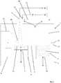
Die in
Oberhalb der Prozesskammer 3 oder im oberen Bereich derselben ist eine Bestrahlungseinrichtung 15, bestehend aus einem Laser 16 und einem Scanner 17 angeordnet. Der hochenergetische Strahl 18 des Lasers 16 wird in den Scanner 17 geleitet und dort in X- und Y-Richtung abgelenkt, um gezielt eine Pulverschicht auf der Oberfläche des Bauteils 14 zu bestrahlen und damit zu verfestigen. Der Scanner 17 wird durch Baudaten gesteuert, die in einem Speicher 19 gespeichert sind und in einem Prozessor 20 so verarbeitet werden, dass ein Prozessorausgang 21 einen Scannereingang mit Scannerinformation bedienen kann.An
Über der Baukammer 6 ist darüber hinaus ein Sensor 31 angeordnet, der dazu geeignet und ausgebildet ist, die zu beschichtende Oberfläche 13 insbesondere des Bauteils 14 vor einem Beschichtungsvorgang durch den Beschichter 12 hinsichtlich seiner Ebenheit abzutasten. Die Abtastung kann derart erfolgen, dass entweder der Sensor 31 als optischer Sensor ausgebildet ist, der entweder selbst einen Sensorstrahl aussendet und die von der Oberfläche zurückgeworfene Information analysiert oder dazu den Strahl des Scanners verwendet. In jedem Fall ist erforderlich, dass der Sensor 31 geeignet ist, Unebenheitskoordinaten bei dem Sensorabtastvorgang zu erfassen und abzuspeichern. Die Abspeicherung der Unebenheitskoordinaten, die auch als Fehlstellenkoordinaten hinsichtlich der zu beschichtenden Oberfläche bezeichnet werden können, erfolgt in einem Speicher 32. In dem Speicher 32 werden nicht nur die X- und Y-Koordinaten der festgestellten Unebenheiten abgelegt, sondern dazu auch die Nummer der Schicht, die aus dem Speicher 19 für die Baudaten übermittelt werden kann. Es ist aber auch möglich, dass der Sensor 31 z.B. als Ultraschallsensor nach Art eines Echolotsensors oder dergleichen ausgebildet ist.Above the
Stellt der Sensor 31 eine Unebenheit auf der zu beschichtenden Oberfläche insbesondere des Bauteils 14 fest, dann werden die X-, Y- und Z-Koordinaten (Z-Koordinate ist Schichtnummer) in dem Speicher 32 abgelegt und eine Abtragevorrichtung z.B. in Form einer Schleifwalze 40 aktiviert, die an einem durch die Speicher 19, 32 gesteuerten Roboterarm 41 angebracht ist. Mit dieser Schleifwalze 40 erfolgt eine lokale Beaufschlagung und ein lokales Abtragen der festgestellten Unebenheitsstellen, zu denen die Koordinaten im Speicher 32 abgelegt sind. Es ist aber auch möglich, festgestellte Unebenheiten abzuschmelzen, d.h. mit der Strahlung 18 des Lasers 16 zu verdampfen oder mit einer Walze, die ähnlich angebracht ist wie die Schleifwalze 40, in die Oberfläche einzuwalzen (nicht erfindungsgemäß).If the
Die Abtastung der Oberfläche 13 mit dem Sensor 31 kann vor jedem erneuten Beschichtungsvorgang erfolgen, es ist unter Umständen aber auch ausreichend, nur nach jedem zweiten, dritten oder fünften Beschichtungsvorgang eine Überprüfung vorzunehmen. Die Abtastung kann ferner nur in den Rand- und Extrembereichen eines Bauteils erfolgen, d.h. bei dünnen Rippen und dergleichen, bei denen eine relativ hohe Delaminationsgefahr besteht.The
In dem Speicher 32 wird nicht nur abgespeichert, dass eine Unebenheit vorgelegen hat und dass diese abgetragen wurde, sondern es wird auch noch der Abtragevorgang genau protokolliert hinsichtlich der Abtragfläche, der Abtragtiefe und dergleichen, weil daraus eine Aussage getroffen werden kann, welcher Art die Unebenheit ist.In the
In
In einem ersten Schritt wird eine zu beschichtende Fläche mit Baumaterial beschichtet, was in vorbezeichneter Weise durch den Beschichter 12 und die Beschichterklinge 11 geschehen kann. Dann wird in einem zweiten Schritt durch die Strahlung 18 des Lasers unter Verwendung des Scanners 17 die Schicht gezielt und lokal verfestigt. Sodann wird in einem dritten Schritt durch den Sensor 31 festgestellt, ob die Schicht eben ist. Falls dies bejaht wird, kann erneut gemäß Schritt 1 eine Beschichtung mit Baumaterial erfolgen. Falls Unebenheiten festgestellt werden, werden die XY-Koordinaten und die Schichtnummer festgehalten und abgespeichert. Sodann erfolgt ein lokaler Abtrag unter Verwendung der XY-Koordinaten und sodann eine Speicherung der Art und der Tiefe des Abtrags unter Verwendung der X-, Y- und Z-Koordinaten.In a first step, a surface to be coated is coated with building material, which can be done in the manner described above by the
Sodann kann ein erneutes lokales Überprüfen des Abtrageergebnisses erfolgen. Stellt sich heraus, dass die Schicht nach wie vor uneben ist, kann erneut festgehalten werden, wo die Schicht noch uneben ist und wo ein weiterer lokaler Abtrag erfolgen muss. Erweist sich die Schicht hingegen als eben, dann erfolgt ein neuer Schichtauftrag mit Baumaterial gemäß Schritt 1.The removal result can then be checked locally again. If it turns out that the layer is still uneven, it can again be recorded where the layer is still uneven and where further local removal has to take place. If, on the other hand, the layer turns out to be flat, a new layer of construction material is applied according to
Es erscheint noch bedeutungsvoll, dass die Fläche der abtragenden Bearbeitung etwas größer sein kann als die tatsächliche Fläche der Unebenheit, um ein wirklich ebenes und glattes Bearbeitungsergebnis sicherzustellen. Diese tatsächlichen Abtragkoordinaten können beispielsweise in dem Speicher 32 der Vorrichtung festgehalten werden, um später Qualitätsmanagementaussagen treffen zu können.It also seems significant that the area of the material to be removed can be somewhat larger than the actual area of the unevenness in order to ensure a really flat and smooth machining result. These actual removal coordinates can, for example, be recorded in the
- 11
- Vorrichtungcontraption
- 22
- Gehäusecasing
- 33
- ProzesskammerProcess chamber
- 44th
- ProzesskammerbodenProcess chamber floor
- 55
- DosierbehälterDosing tank
- 66th
- BaukammerBuilding chamber
- 77th
- Trägercarrier
- 88th
- ÜberlaufbehälterOverflow tank
- 99
- BaumaterialBuilding material
- 1010
- DosierkammerbodenDosing chamber floor
- 1111
- Klingeblade
- 1212th
- BeschichterCoater
- 1313th
- Oberflächesurface
- 1414th
- BauteilComponent
- 1515th
- BestrahlungseinrichtungIrradiation facility
- 1616
- Laserlaser
- 1717th
- Scannerscanner
- 1818th
- Strahl v. 16Ray v. 16
- 1919th
- SpeicherStorage
- 2020th
- Prozessorprocessor
- 2121
- Ausgang v. 20Exit v. 20th
- 3131
- Sensorsensor
- 3232
- SpeicherStorage
- 4040
- SchleifwalzeSanding roller
- 4141
- RoboterarmRobotic arm
Claims (9)
- Method for producing three-dimensional components (14) by successively solidifying layers of a powdery construction material (9), which can be solidified by means of electromagnetic radiation (18), in particular bundled radiation such as laser radiation or electron radiation, at the points corresponding to the relevant cross section of the component (14), in particular selective laser melting (SLM) or selective laser sintering (SLS) methods, wherein a device (1) is provided with a supporting device (7) that is height-adjustable within a construction chamber (6) for supporting the component (14), comprising a coating device (12) for applying layers of the construction material (9) to the supporting device or a previously formed layer, and comprising an irradiation apparatus (15) for irradiating layers of the construction material (9) in regions in order to solidify said layers, wherein a portion of the surface (13) to be coated is scanned for its evenness before another layer is applied and, if there is unevenness that exceeds a certain tolerance range, this unevenness is removed,characterised in that a portion of the surface to be coated is scanned using a sensor with unevenness coordinates being recorded, wherein the locally identified unevenness is locally mechanical removed in a targeted manner using the identified unevenness coordinates, wherein a removal element having a relatively small surface area is guided to an upwardly protruding point on the layer and the removal process is carried out here.
- Method according to claim 1,characterised in that the surface (13) to be coated is scanned optically.
- Method according to claim 1 or 2,characterised in that the surface (13) is scanned by means of an acoustic method, in particular an ultrasound method.
- Method according to any of the preceding claims,characterised in that the surface (13) to be coated is scanned before each coating process.
- Method according to any of the preceding claims,characterised in that the surface (13) to be coated is only scanned in edge regions or overhang regions of the component.
- Method according to any of the preceding claims,characterised in that delamination of layers of the component (14) already solidified is detected by means of the scanning.
- Method according to any of the preceding claims,characterised in that there is a plurality of coating processes between the scanning processes.
- Method according to any of the preceding claims,characterised in that a detection process and/or a removal process is automatically stored in a quality-management record, which is compiled for the relevant component (14), with regard to a build-up layer that has been partially removed and/or determined as being uneven and with regard to the associated X and Y coordinates and the layer number (Z coordinate in the component).
- Method according to claim 8,characterised in that the type of removal and/or the removal depth is also automatically stored in addition to the X and Y coordinates.
Applications Claiming Priority (2)
| Application Number | Priority Date | Filing Date | Title |
|---|---|---|---|
| DE102015000100.0ADE102015000100A1 (en) | 2015-01-14 | 2015-01-14 | Method for the production of three-dimensional components |
| PCT/EP2016/050472WO2016113255A1 (en) | 2015-01-14 | 2016-01-12 | Method for producing three-dimensional components |
Publications (2)
| Publication Number | Publication Date |
|---|---|
| EP3245042A1 EP3245042A1 (en) | 2017-11-22 |
| EP3245042B1true EP3245042B1 (en) | 2021-04-07 |
Family
ID=55085669
Family Applications (1)
| Application Number | Title | Priority Date | Filing Date |
|---|---|---|---|
| EP16700354.0AActiveEP3245042B1 (en) | 2015-01-14 | 2016-01-12 | Method for producing three-dimensional components |
Country Status (6)
| Country | Link |
|---|---|
| US (1) | US11370028B2 (en) |
| EP (1) | EP3245042B1 (en) |
| JP (2) | JP2018502748A (en) |
| CN (1) | CN107206679B (en) |
| DE (1) | DE102015000100A1 (en) |
| WO (1) | WO2016113255A1 (en) |
Families Citing this family (15)
| Publication number | Priority date | Publication date | Assignee | Title |
|---|---|---|---|---|
| US20170355018A1 (en)* | 2016-06-09 | 2017-12-14 | Hamilton Sundstrand Corporation | Powder deposition for additive manufacturing |
| DE102016226035A1 (en)* | 2016-12-22 | 2018-06-28 | Airbus Defence and Space GmbH | Component for rotatable storage and method for producing the component |
| CN106903314B (en)* | 2017-04-16 | 2019-03-29 | 吉林大学 | Ultrasonic constituency lamination increasing material manufacturing device and method |
| US20190134891A1 (en)* | 2017-11-08 | 2019-05-09 | General Electric Company | Dmlm build platform and surface flattening |
| US10759114B2 (en)* | 2017-12-29 | 2020-09-01 | Continuous Composites Inc. | System and print head for continuously manufacturing composite structure |
| EP3517298B1 (en) | 2018-01-26 | 2022-12-07 | CL Schutzrechtsverwaltungs GmbH | Build material application device |
| DE102018201255A1 (en)* | 2018-01-29 | 2019-08-01 | MTU Aero Engines AG | Layer construction method and layer construction device for the additive production of at least one component region of a component |
| JP7066597B2 (en)* | 2018-11-22 | 2022-05-13 | ローランドディー.ジー.株式会社 | 3D modeling equipment |
| IT201800010598A1 (en)* | 2018-11-27 | 2020-05-27 | Milano Politecnico | DEVICE FOR THE IN SITU REMOVAL OF DEFECTS DURING ADDITIVE PRINTING OF METALLIC PARTS |
| CN111703071A (en)* | 2020-06-17 | 2020-09-25 | 天津清研智束科技有限公司 | Additive manufacturing device and additive manufacturing method |
| CN112620654A (en)* | 2020-12-14 | 2021-04-09 | 合肥新杉宇航三维科技有限公司 | Layer-by-layer selective impurity cleaning device and process for 3D printing of metal |
| CN112643055A (en)* | 2020-12-16 | 2021-04-13 | 重庆机电增材制造有限公司 | Part warp deformation correcting device |
| EP4366939A1 (en)* | 2021-07-09 | 2024-05-15 | Reset Technology Corporation | Network enabled 3d printing and automated processing techniques for oral devices |
| EP4563927A1 (en) | 2023-11-30 | 2025-06-04 | Technische Universiteit Eindhoven | Heat pipe |
| CN120519854B (en)* | 2025-07-28 | 2025-09-19 | 太原科技大学 | Ultrasonic-assisted laser cladding device |
Family Cites Families (25)
| Publication number | Priority date | Publication date | Assignee | Title |
|---|---|---|---|---|
| DE19853978C1 (en) | 1998-11-23 | 2000-05-25 | Fraunhofer Ges Forschung | Apparatus for selective laser smelting comprises a roller that moves over the processing surface using an element to distribute powder |
| DE19905067A1 (en)* | 1999-02-08 | 2000-08-10 | Matthias Fockele | Layer-wise molding build-up apparatus, especially for laser prototyping of metallic articles, has a grinding tool for removing irregularities from a previously laser melted and solidified layer region |
| SE521124C2 (en)* | 2000-04-27 | 2003-09-30 | Arcam Ab | Device and method for making a three-dimensional product |
| JP3446733B2 (en) | 2000-10-05 | 2003-09-16 | 松下電工株式会社 | Method and apparatus for manufacturing three-dimensional shaped object |
| TW506868B (en)* | 2000-10-05 | 2002-10-21 | Matsushita Electric Works Ltd | Method of and apparatus for making a three-dimensional object |
| DE10058748C1 (en) | 2000-11-27 | 2002-07-25 | Markus Dirscherl | Method for producing a component and device for carrying out the method |
| US6492651B2 (en) | 2001-02-08 | 2002-12-10 | 3D Systems, Inc. | Surface scanning system for selective deposition modeling |
| EP1234625A1 (en)* | 2001-02-21 | 2002-08-28 | Trumpf Werkzeugmaschinen GmbH + Co. KG | Process and apparatus for producing a shaped body by selective laser sintering |
| SE524421C2 (en)* | 2002-12-19 | 2004-08-10 | Arcam Ab | Apparatus and method for making a three-dimensional product |
| DE10300959C5 (en) | 2003-01-14 | 2013-10-02 | Cl Schutzrechtsverwaltungs Gmbh | Coater device for a building device for producing molded parts from building material |
| DE112004000302B3 (en)* | 2003-02-25 | 2010-08-26 | Panasonic Electric Works Co., Ltd., Kadoma-shi | Method and device for producing a three-dimensional object |
| JP3599059B2 (en) | 2003-02-25 | 2004-12-08 | 松下電工株式会社 | Method and apparatus for manufacturing three-dimensional shaped object |
| GB0601982D0 (en)* | 2006-02-01 | 2006-03-15 | Rolls Royce Plc | Method and apparatus for examination of objects and structures |
| US20070295440A1 (en)* | 2006-05-24 | 2007-12-27 | Stucker Brent E | Surface roughness reduction for improving bonding in ultrasonic consolidation rapid manufacturing |
| JP2008194107A (en)* | 2007-02-09 | 2008-08-28 | Shiyoufuu:Kk | Three-dimensional characteristic measuring and displaying apparatus for dental use |
| WO2010150805A1 (en)* | 2009-06-23 | 2010-12-29 | パナソニック電工株式会社 | Method for producing three-dimensional formed shapes, and three-dimensional formed shapes obtained thereby |
| DE202010010771U1 (en) | 2010-07-28 | 2011-11-14 | Cl Schutzrechtsverwaltungs Gmbh | Laser melting apparatus for producing a three-dimensional component |
| DE102011006941A1 (en)* | 2010-11-26 | 2012-05-31 | Mtu Aero Engines Gmbh | Process for the layered production of a component and device |
| FR2974316B1 (en) | 2011-04-19 | 2015-10-09 | Phenix Systems | PROCESS FOR PRODUCING AN OBJECT BY SOLIDIFYING A POWDER USING A LASER |
| JP5877471B2 (en)* | 2011-05-23 | 2016-03-08 | パナソニックIpマネジメント株式会社 | Manufacturing method of three-dimensional shaped object |
| DE102012012412A1 (en)* | 2012-06-25 | 2014-03-20 | Cl Schutzrechtsverwaltungs Gmbh | Apparatus, useful for producing three-dimensional objects, includes construction material, supporting unit, and applying device for application of material, where applying device includes guided blade assembly having blades holder |
| GB201313841D0 (en) | 2013-08-02 | 2013-09-18 | Rolls Royce Plc | Method of Manufacturing a Component |
| US20170001379A1 (en)* | 2014-02-05 | 2017-01-05 | United Technologies Corporation | A self-monitoring additive manufacturing system and method of operation |
| DE102014204528A1 (en) | 2014-03-12 | 2015-09-17 | Siemens Aktiengesellschaft | Method and device for selective laser melting |
| JP2017530033A (en)* | 2014-09-19 | 2017-10-12 | ムーグ インコーポレイテッド | Method for removing defects layer by layer during additive manufacturing |
- 2015
- 2015-01-14DEDE102015000100.0Apatent/DE102015000100A1/enactivePending
- 2016
- 2016-01-12WOPCT/EP2016/050472patent/WO2016113255A1/ennot_activeCeased
- 2016-01-12EPEP16700354.0Apatent/EP3245042B1/enactiveActive
- 2016-01-12JPJP2017537235Apatent/JP2018502748A/enactivePending
- 2016-01-12CNCN201680005703.0Apatent/CN107206679B/enactiveActive
- 2016-01-12USUS15/541,345patent/US11370028B2/enactiveActive
- 2020
- 2020-02-04JPJP2020017139Apatent/JP7004337B2/enactiveActive
Non-Patent Citations (1)
| Title |
|---|
| None* |
Also Published As
| Publication number | Publication date |
|---|---|
| JP2020097240A (en) | 2020-06-25 |
| JP2018502748A (en) | 2018-02-01 |
| US11370028B2 (en) | 2022-06-28 |
| JP7004337B2 (en) | 2022-02-10 |
| EP3245042A1 (en) | 2017-11-22 |
| CN107206679A (en) | 2017-09-26 |
| WO2016113255A1 (en) | 2016-07-21 |
| US20170368757A1 (en) | 2017-12-28 |
| DE102015000100A1 (en) | 2016-07-14 |
| CN107206679B (en) | 2021-07-27 |
Similar Documents
| Publication | Publication Date | Title |
|---|---|---|
| EP3245042B1 (en) | Method for producing three-dimensional components | |
| EP3225334B1 (en) | Method and apparatus for additive manufacture of at least one component area of a component | |
| EP3285943B1 (en) | Method for producing a three-dimensional component | |
| DE102008012063B4 (en) | Process for the preparation of a hybrid molding | |
| DE202006016477U1 (en) | Rapid prototyping apparatus for producing three-dimensional object, comprises carrier whose height is fixed and retaining wall whose height is adjusted by program-controlled adjuster | |
| DE112011100572T5 (en) | METHOD FOR PRODUCING A THREE-DIMENSIONAL FORM AND THREE-DIMENSIONAL MOLDING OBJECT | |
| EP2643112B1 (en) | Method for the layered manufacturing of a structural component | |
| DE102014004633A1 (en) | Device for producing three-dimensional objects by successively solidifying layers | |
| DE102010029078A1 (en) | Producing an article by layer-wise structures made of powdered metallic or ceramic material, comprises individually preparing material powder layers subsequent to each other on a support, and location-selectively solidifying each layer | |
| DE102016222609A1 (en) | Apparatus for three-dimensional modeling, method, program and storage medium for three-dimensional modeling | |
| EP3579998A1 (en) | Increase in surface quality | |
| EP3579996A1 (en) | Light exposure strategy in multiple-beam am systems | |
| DE102016212063A1 (en) | Apparatus and method for irradiation control in a device for producing a three-dimensional object | |
| DE102016203955A1 (en) | Generative layer construction method with improved detail resolution and apparatus for carrying it out | |
| DE102014014888A1 (en) | Method for setting up and adjusting a building board | |
| DE102016209618A1 (en) | Method and device for the additive production of at least one component region of a component | |
| DE102015224395A1 (en) | Device and method for producing a component in a layered construction, use of a detection device in a layer construction method | |
| WO2020094672A1 (en) | Method for operating a manufacturing device and manufacturing device for the additive manufacturing of a component from a powder material | |
| WO1996014203A1 (en) | Process and device for producing a three-dimensional object | |
| DE102017207832A1 (en) | Position-specific energy input | |
| WO2024146672A1 (en) | Method and device for producing micro parts and micro components by means of additive manufacturing using micro laser sintering | |
| EP2848392A1 (en) | Method for ensuring the quality of components made by means of generative production processes and system | |
| EP2221166A2 (en) | Rapid protyping device and method with indirect laser irradiation | |
| DE102018215983A1 (en) | Calculation of exposure paths with low component distortion | |
| EP2929962A1 (en) | Method and device for improving material quality in generative production methods |
Legal Events
| Date | Code | Title | Description |
|---|---|---|---|
| STAA | Information on the status of an ep patent application or granted ep patent | Free format text:STATUS: THE INTERNATIONAL PUBLICATION HAS BEEN MADE | |
| PUAI | Public reference made under article 153(3) epc to a published international application that has entered the european phase | Free format text:ORIGINAL CODE: 0009012 | |
| STAA | Information on the status of an ep patent application or granted ep patent | Free format text:STATUS: REQUEST FOR EXAMINATION WAS MADE | |
| 17P | Request for examination filed | Effective date:20170702 | |
| AK | Designated contracting states | Kind code of ref document:A1 Designated state(s):AL AT BE BG CH CY CZ DE DK EE ES FI FR GB GR HR HU IE IS IT LI LT LU LV MC MK MT NL NO PL PT RO RS SE SI SK SM TR | |
| AX | Request for extension of the european patent | Extension state:BA ME | |
| DAV | Request for validation of the european patent (deleted) | ||
| DAX | Request for extension of the european patent (deleted) | ||
| STAA | Information on the status of an ep patent application or granted ep patent | Free format text:STATUS: EXAMINATION IS IN PROGRESS | |
| 17Q | First examination report despatched | Effective date:20200420 | |
| REG | Reference to a national code | Ref country code:DE Ref legal event code:R079 Ref document number:502016012750 Country of ref document:DE Free format text:PREVIOUS MAIN CLASS: B29C0067000000 Ipc:B29C0064153000 | |
| GRAP | Despatch of communication of intention to grant a patent | Free format text:ORIGINAL CODE: EPIDOSNIGR1 | |
| STAA | Information on the status of an ep patent application or granted ep patent | Free format text:STATUS: GRANT OF PATENT IS INTENDED | |
| RIC1 | Information provided on ipc code assigned before grant | Ipc:B29C 64/188 20170101ALI20200929BHEP Ipc:B22F 3/16 20060101ALI20200929BHEP Ipc:B29C 64/393 20170101ALI20200929BHEP Ipc:B22F 3/105 20060101ALI20200929BHEP Ipc:B29C 64/153 20170101AFI20200929BHEP | |
| INTG | Intention to grant announced | Effective date:20201020 | |
| GRAS | Grant fee paid | Free format text:ORIGINAL CODE: EPIDOSNIGR3 | |
| GRAA | (expected) grant | Free format text:ORIGINAL CODE: 0009210 | |
| STAA | Information on the status of an ep patent application or granted ep patent | Free format text:STATUS: THE PATENT HAS BEEN GRANTED | |
| AK | Designated contracting states | Kind code of ref document:B1 Designated state(s):AL AT BE BG CH CY CZ DE DK EE ES FI FR GB GR HR HU IE IS IT LI LT LU LV MC MK MT NL NO PL PT RO RS SE SI SK SM TR | |
| REG | Reference to a national code | Ref country code:GB Ref legal event code:FG4D Free format text:NOT ENGLISH | |
| REG | Reference to a national code | Ref country code:AT Ref legal event code:REF Ref document number:1379112 Country of ref document:AT Kind code of ref document:T Effective date:20210415 Ref country code:CH Ref legal event code:EP | |
| REG | Reference to a national code | Ref country code:DE Ref legal event code:R096 Ref document number:502016012750 Country of ref document:DE | |
| REG | Reference to a national code | Ref country code:IE Ref legal event code:FG4D Free format text:LANGUAGE OF EP DOCUMENT: GERMAN | |
| REG | Reference to a national code | Ref country code:LT Ref legal event code:MG9D | |
| REG | Reference to a national code | Ref country code:NL Ref legal event code:MP Effective date:20210407 | |
| PG25 | Lapsed in a contracting state [announced via postgrant information from national office to epo] | Ref country code:HR Free format text:LAPSE BECAUSE OF FAILURE TO SUBMIT A TRANSLATION OF THE DESCRIPTION OR TO PAY THE FEE WITHIN THE PRESCRIBED TIME-LIMIT Effective date:20210407 Ref country code:BG Free format text:LAPSE BECAUSE OF FAILURE TO SUBMIT A TRANSLATION OF THE DESCRIPTION OR TO PAY THE FEE WITHIN THE PRESCRIBED TIME-LIMIT Effective date:20210707 Ref country code:LT Free format text:LAPSE BECAUSE OF FAILURE TO SUBMIT A TRANSLATION OF THE DESCRIPTION OR TO PAY THE FEE WITHIN THE PRESCRIBED TIME-LIMIT Effective date:20210407 Ref country code:NL Free format text:LAPSE BECAUSE OF FAILURE TO SUBMIT A TRANSLATION OF THE DESCRIPTION OR TO PAY THE FEE WITHIN THE PRESCRIBED TIME-LIMIT Effective date:20210407 Ref country code:FI Free format text:LAPSE BECAUSE OF FAILURE TO SUBMIT A TRANSLATION OF THE DESCRIPTION OR TO PAY THE FEE WITHIN THE PRESCRIBED TIME-LIMIT Effective date:20210407 | |
| PG25 | Lapsed in a contracting state [announced via postgrant information from national office to epo] | Ref country code:LV Free format text:LAPSE BECAUSE OF FAILURE TO SUBMIT A TRANSLATION OF THE DESCRIPTION OR TO PAY THE FEE WITHIN THE PRESCRIBED TIME-LIMIT Effective date:20210407 Ref country code:GR Free format text:LAPSE BECAUSE OF FAILURE TO SUBMIT A TRANSLATION OF THE DESCRIPTION OR TO PAY THE FEE WITHIN THE PRESCRIBED TIME-LIMIT Effective date:20210708 Ref country code:IS Free format text:LAPSE BECAUSE OF FAILURE TO SUBMIT A TRANSLATION OF THE DESCRIPTION OR TO PAY THE FEE WITHIN THE PRESCRIBED TIME-LIMIT Effective date:20210807 Ref country code:RS Free format text:LAPSE BECAUSE OF FAILURE TO SUBMIT A TRANSLATION OF THE DESCRIPTION OR TO PAY THE FEE WITHIN THE PRESCRIBED TIME-LIMIT Effective date:20210407 Ref country code:SE Free format text:LAPSE BECAUSE OF FAILURE TO SUBMIT A TRANSLATION OF THE DESCRIPTION OR TO PAY THE FEE WITHIN THE PRESCRIBED TIME-LIMIT Effective date:20210407 Ref country code:NO Free format text:LAPSE BECAUSE OF FAILURE TO SUBMIT A TRANSLATION OF THE DESCRIPTION OR TO PAY THE FEE WITHIN THE PRESCRIBED TIME-LIMIT Effective date:20210707 Ref country code:PT Free format text:LAPSE BECAUSE OF FAILURE TO SUBMIT A TRANSLATION OF THE DESCRIPTION OR TO PAY THE FEE WITHIN THE PRESCRIBED TIME-LIMIT Effective date:20210809 Ref country code:PL Free format text:LAPSE BECAUSE OF FAILURE TO SUBMIT A TRANSLATION OF THE DESCRIPTION OR TO PAY THE FEE WITHIN THE PRESCRIBED TIME-LIMIT Effective date:20210407 | |
| REG | Reference to a national code | Ref country code:DE Ref legal event code:R097 Ref document number:502016012750 Country of ref document:DE | |
| PG25 | Lapsed in a contracting state [announced via postgrant information from national office to epo] | Ref country code:EE Free format text:LAPSE BECAUSE OF FAILURE TO SUBMIT A TRANSLATION OF THE DESCRIPTION OR TO PAY THE FEE WITHIN THE PRESCRIBED TIME-LIMIT Effective date:20210407 Ref country code:CZ Free format text:LAPSE BECAUSE OF FAILURE TO SUBMIT A TRANSLATION OF THE DESCRIPTION OR TO PAY THE FEE WITHIN THE PRESCRIBED TIME-LIMIT Effective date:20210407 Ref country code:DK Free format text:LAPSE BECAUSE OF FAILURE TO SUBMIT A TRANSLATION OF THE DESCRIPTION OR TO PAY THE FEE WITHIN THE PRESCRIBED TIME-LIMIT Effective date:20210407 Ref country code:SM Free format text:LAPSE BECAUSE OF FAILURE TO SUBMIT A TRANSLATION OF THE DESCRIPTION OR TO PAY THE FEE WITHIN THE PRESCRIBED TIME-LIMIT Effective date:20210407 Ref country code:SK Free format text:LAPSE BECAUSE OF FAILURE TO SUBMIT A TRANSLATION OF THE DESCRIPTION OR TO PAY THE FEE WITHIN THE PRESCRIBED TIME-LIMIT Effective date:20210407 Ref country code:RO Free format text:LAPSE BECAUSE OF FAILURE TO SUBMIT A TRANSLATION OF THE DESCRIPTION OR TO PAY THE FEE WITHIN THE PRESCRIBED TIME-LIMIT Effective date:20210407 Ref country code:ES Free format text:LAPSE BECAUSE OF FAILURE TO SUBMIT A TRANSLATION OF THE DESCRIPTION OR TO PAY THE FEE WITHIN THE PRESCRIBED TIME-LIMIT Effective date:20210407 | |
| PLBE | No opposition filed within time limit | Free format text:ORIGINAL CODE: 0009261 | |
| STAA | Information on the status of an ep patent application or granted ep patent | Free format text:STATUS: NO OPPOSITION FILED WITHIN TIME LIMIT | |
| 26N | No opposition filed | Effective date:20220110 | |
| PG25 | Lapsed in a contracting state [announced via postgrant information from national office to epo] | Ref country code:IS Free format text:LAPSE BECAUSE OF FAILURE TO SUBMIT A TRANSLATION OF THE DESCRIPTION OR TO PAY THE FEE WITHIN THE PRESCRIBED TIME-LIMIT Effective date:20210807 Ref country code:AL Free format text:LAPSE BECAUSE OF FAILURE TO SUBMIT A TRANSLATION OF THE DESCRIPTION OR TO PAY THE FEE WITHIN THE PRESCRIBED TIME-LIMIT Effective date:20210407 | |
| PG25 | Lapsed in a contracting state [announced via postgrant information from national office to epo] | Ref country code:IT Free format text:LAPSE BECAUSE OF FAILURE TO SUBMIT A TRANSLATION OF THE DESCRIPTION OR TO PAY THE FEE WITHIN THE PRESCRIBED TIME-LIMIT Effective date:20210407 | |
| PG25 | Lapsed in a contracting state [announced via postgrant information from national office to epo] | Ref country code:MC Free format text:LAPSE BECAUSE OF FAILURE TO SUBMIT A TRANSLATION OF THE DESCRIPTION OR TO PAY THE FEE WITHIN THE PRESCRIBED TIME-LIMIT Effective date:20210407 | |
| REG | Reference to a national code | Ref country code:CH Ref legal event code:PL | |
| GBPC | Gb: european patent ceased through non-payment of renewal fee | Effective date:20220112 | |
| REG | Reference to a national code | Ref country code:BE Ref legal event code:MM Effective date:20220131 | |
| PG25 | Lapsed in a contracting state [announced via postgrant information from national office to epo] | Ref country code:LU Free format text:LAPSE BECAUSE OF NON-PAYMENT OF DUE FEES Effective date:20220112 Ref country code:GB Free format text:LAPSE BECAUSE OF NON-PAYMENT OF DUE FEES Effective date:20220112 | |
| PG25 | Lapsed in a contracting state [announced via postgrant information from national office to epo] | Ref country code:FR Free format text:LAPSE BECAUSE OF NON-PAYMENT OF DUE FEES Effective date:20220131 Ref country code:BE Free format text:LAPSE BECAUSE OF NON-PAYMENT OF DUE FEES Effective date:20220131 | |
| PG25 | Lapsed in a contracting state [announced via postgrant information from national office to epo] | Ref country code:LI Free format text:LAPSE BECAUSE OF NON-PAYMENT OF DUE FEES Effective date:20220131 Ref country code:CH Free format text:LAPSE BECAUSE OF NON-PAYMENT OF DUE FEES Effective date:20220131 | |
| PG25 | Lapsed in a contracting state [announced via postgrant information from national office to epo] | Ref country code:IE Free format text:LAPSE BECAUSE OF NON-PAYMENT OF DUE FEES Effective date:20220112 | |
| REG | Reference to a national code | Ref country code:DE Ref legal event code:R081 Ref document number:502016012750 Country of ref document:DE Owner name:CONCEPT LASER GMBH, DE Free format text:FORMER OWNER: CL SCHUTZRECHTSVERWALTUNGS GMBH, 96215 LICHTENFELS, DE | |
| REG | Reference to a national code | Ref country code:AT Ref legal event code:MM01 Ref document number:1379112 Country of ref document:AT Kind code of ref document:T Effective date:20220112 | |
| PG25 | Lapsed in a contracting state [announced via postgrant information from national office to epo] | Ref country code:AT Free format text:LAPSE BECAUSE OF NON-PAYMENT OF DUE FEES Effective date:20220112 | |
| P01 | Opt-out of the competence of the unified patent court (upc) registered | Effective date:20230517 | |
| P02 | Opt-out of the competence of the unified patent court (upc) changed | Effective date:20230606 | |
| PG25 | Lapsed in a contracting state [announced via postgrant information from national office to epo] | Ref country code:HU Free format text:LAPSE BECAUSE OF FAILURE TO SUBMIT A TRANSLATION OF THE DESCRIPTION OR TO PAY THE FEE WITHIN THE PRESCRIBED TIME-LIMIT; INVALID AB INITIO Effective date:20160112 | |
| PG25 | Lapsed in a contracting state [announced via postgrant information from national office to epo] | Ref country code:MK Free format text:LAPSE BECAUSE OF FAILURE TO SUBMIT A TRANSLATION OF THE DESCRIPTION OR TO PAY THE FEE WITHIN THE PRESCRIBED TIME-LIMIT Effective date:20210407 Ref country code:CY Free format text:LAPSE BECAUSE OF FAILURE TO SUBMIT A TRANSLATION OF THE DESCRIPTION OR TO PAY THE FEE WITHIN THE PRESCRIBED TIME-LIMIT Effective date:20210407 | |
| PG25 | Lapsed in a contracting state [announced via postgrant information from national office to epo] | Ref country code:MT Free format text:LAPSE BECAUSE OF FAILURE TO SUBMIT A TRANSLATION OF THE DESCRIPTION OR TO PAY THE FEE WITHIN THE PRESCRIBED TIME-LIMIT Effective date:20210407 | |
| PGFP | Annual fee paid to national office [announced via postgrant information from national office to epo] | Ref country code:DE Payment date:20241218 Year of fee payment:10 |