EP3244835B1 - Method for manufacturing an auxiliary device suitable for the manufacture of a patient customized implant - Google Patents
Method for manufacturing an auxiliary device suitable for the manufacture of a patient customized implantDownload PDFInfo
- Publication number
- EP3244835B1 EP3244835B1EP15700838.4AEP15700838AEP3244835B1EP 3244835 B1EP3244835 B1EP 3244835B1EP 15700838 AEP15700838 AEP 15700838AEP 3244835 B1EP3244835 B1EP 3244835B1
- Authority
- EP
- European Patent Office
- Prior art keywords
- auxiliary device
- implant
- recess
- defect site
- size
- Prior art date
- Legal status (The legal status is an assumption and is not a legal conclusion. Google has not performed a legal analysis and makes no representation as to the accuracy of the status listed.)
- Active
Links
- 239000007943implantSubstances0.000titleclaimsdescription89
- 238000000034methodMethods0.000titleclaimsdescription53
- 238000004519manufacturing processMethods0.000titleclaimsdescription31
- 230000007547defectEffects0.000claimsdescription56
- 239000011347resinSubstances0.000claimsdescription13
- 229920005989resinPolymers0.000claimsdescription13
- RTAQQCXQSZGOHL-UHFFFAOYSA-NTitaniumChemical compound[Ti]RTAQQCXQSZGOHL-UHFFFAOYSA-N0.000claimsdescription9
- 210000003484anatomyAnatomy0.000claimsdescription9
- 230000002093peripheral effectEffects0.000claimsdescription9
- 238000005094computer simulationMethods0.000claimsdescription8
- 239000000463materialSubstances0.000claimsdescription8
- 238000005516engineering processMethods0.000claimsdescription7
- 238000003384imaging methodMethods0.000claimsdescription6
- 229910052719titaniumInorganic materials0.000claimsdescription6
- 239000010936titaniumSubstances0.000claimsdescription6
- 2380000101463D printingMethods0.000claimsdescription4
- 238000000016photochemical curingMethods0.000claimsdescription4
- 238000002513implantationMethods0.000claimsdescription3
- 238000012545processingMethods0.000claimsdescription3
- 238000001356surgical procedureMethods0.000description12
- 238000013461designMethods0.000description9
- 238000002591computed tomographyMethods0.000description7
- 230000008569processEffects0.000description7
- 239000011159matrix materialSubstances0.000description5
- 239000007787solidSubstances0.000description5
- 238000001723curingMethods0.000description4
- 239000000203mixtureSubstances0.000description4
- 230000008901benefitEffects0.000description3
- 238000007493shaping processMethods0.000description3
- 125000006850spacer groupChemical group0.000description3
- 206010017076FractureDiseases0.000description2
- SECXISVLQFMRJM-UHFFFAOYSA-NN-MethylpyrrolidoneChemical compoundCN1CCCC1=OSECXISVLQFMRJM-UHFFFAOYSA-N0.000description2
- 239000000560biocompatible materialSubstances0.000description2
- 210000000988bone and boneAnatomy0.000description2
- 238000006073displacement reactionMethods0.000description2
- 238000010348incorporationMethods0.000description2
- 238000012986modificationMethods0.000description2
- 230000004048modificationEffects0.000description2
- 210000004872soft tissueAnatomy0.000description2
- 210000001519tissueAnatomy0.000description2
- 206010003694AtrophyDiseases0.000description1
- 238000012935AveragingMethods0.000description1
- 208000010392Bone FracturesDiseases0.000description1
- 208000002021EnophthalmosDiseases0.000description1
- 208000007825Orbital FracturesDiseases0.000description1
- 206010068548Soft tissue atrophyDiseases0.000description1
- 238000004458analytical methodMethods0.000description1
- 238000013459approachMethods0.000description1
- 230000037444atrophyEffects0.000description1
- 230000008859changeEffects0.000description1
- 230000001054cortical effectEffects0.000description1
- 230000004064dysfunctionEffects0.000description1
- 210000002454frontal boneAnatomy0.000description1
- 230000001771impaired effectEffects0.000description1
- 208000014674injuryDiseases0.000description1
- 238000007918intramuscular administrationMethods0.000description1
- 238000003475laminationMethods0.000description1
- 238000002386leachingMethods0.000description1
- 210000002050maxillaAnatomy0.000description1
- 230000004899motilityEffects0.000description1
- 238000000465mouldingMethods0.000description1
- 230000000399orthopedic effectEffects0.000description1
- 238000001556precipitationMethods0.000description1
- 230000008439repair processEffects0.000description1
- 230000000717retained effectEffects0.000description1
- 238000012552reviewMethods0.000description1
- 238000002791soakingMethods0.000description1
- 239000002904solventSubstances0.000description1
- 238000003860storageMethods0.000description1
- 210000003582temporal boneAnatomy0.000description1
- 230000009466transformationEffects0.000description1
- 238000000844transformationMethods0.000description1
- 230000008733traumaEffects0.000description1
- XLYOFNOQVPJJNP-UHFFFAOYSA-NwaterSubstancesOXLYOFNOQVPJJNP-UHFFFAOYSA-N0.000description1
Images

Classifications
- A—HUMAN NECESSITIES
- A61—MEDICAL OR VETERINARY SCIENCE; HYGIENE
- A61F—FILTERS IMPLANTABLE INTO BLOOD VESSELS; PROSTHESES; DEVICES PROVIDING PATENCY TO, OR PREVENTING COLLAPSING OF, TUBULAR STRUCTURES OF THE BODY, e.g. STENTS; ORTHOPAEDIC, NURSING OR CONTRACEPTIVE DEVICES; FOMENTATION; TREATMENT OR PROTECTION OF EYES OR EARS; BANDAGES, DRESSINGS OR ABSORBENT PADS; FIRST-AID KITS
- A61F2/00—Filters implantable into blood vessels; Prostheses, i.e. artificial substitutes or replacements for parts of the body; Appliances for connecting them with the body; Devices providing patency to, or preventing collapsing of, tubular structures of the body, e.g. stents
- A61F2/02—Prostheses implantable into the body
- A61F2/30—Joints
- A61F2/3094—Designing or manufacturing processes
- A61F2/30942—Designing or manufacturing processes for designing or making customized prostheses, e.g. using templates, CT or NMR scans, finite-element analysis or CAD-CAM techniques
- A—HUMAN NECESSITIES
- A61—MEDICAL OR VETERINARY SCIENCE; HYGIENE
- A61B—DIAGNOSIS; SURGERY; IDENTIFICATION
- A61B17/00—Surgical instruments, devices or methods
- A61B17/56—Surgical instruments or methods for treatment of bones or joints; Devices specially adapted therefor
- A61B17/58—Surgical instruments or methods for treatment of bones or joints; Devices specially adapted therefor for osteosynthesis, e.g. bone plates, screws or setting implements
- A61B17/68—Internal fixation devices, including fasteners and spinal fixators, even if a part thereof projects from the skin
- A61B17/80—Cortical plates, i.e. bone plates; Instruments for holding or positioning cortical plates, or for compressing bones attached to cortical plates
- A61B17/8061—Cortical plates, i.e. bone plates; Instruments for holding or positioning cortical plates, or for compressing bones attached to cortical plates specially adapted for particular bones
- A—HUMAN NECESSITIES
- A61—MEDICAL OR VETERINARY SCIENCE; HYGIENE
- A61B—DIAGNOSIS; SURGERY; IDENTIFICATION
- A61B34/00—Computer-aided surgery; Manipulators or robots specially adapted for use in surgery
- A61B34/10—Computer-aided planning, simulation or modelling of surgical operations
- A—HUMAN NECESSITIES
- A61—MEDICAL OR VETERINARY SCIENCE; HYGIENE
- A61F—FILTERS IMPLANTABLE INTO BLOOD VESSELS; PROSTHESES; DEVICES PROVIDING PATENCY TO, OR PREVENTING COLLAPSING OF, TUBULAR STRUCTURES OF THE BODY, e.g. STENTS; ORTHOPAEDIC, NURSING OR CONTRACEPTIVE DEVICES; FOMENTATION; TREATMENT OR PROTECTION OF EYES OR EARS; BANDAGES, DRESSINGS OR ABSORBENT PADS; FIRST-AID KITS
- A61F2/00—Filters implantable into blood vessels; Prostheses, i.e. artificial substitutes or replacements for parts of the body; Appliances for connecting them with the body; Devices providing patency to, or preventing collapsing of, tubular structures of the body, e.g. stents
- A61F2/02—Prostheses implantable into the body
- A61F2/28—Bones
- A61F2/2875—Skull or cranium
- A—HUMAN NECESSITIES
- A61—MEDICAL OR VETERINARY SCIENCE; HYGIENE
- A61B—DIAGNOSIS; SURGERY; IDENTIFICATION
- A61B34/00—Computer-aided surgery; Manipulators or robots specially adapted for use in surgery
- A61B34/10—Computer-aided planning, simulation or modelling of surgical operations
- A61B2034/101—Computer-aided simulation of surgical operations
- A61B2034/102—Modelling of surgical devices, implants or prosthesis
- A—HUMAN NECESSITIES
- A61—MEDICAL OR VETERINARY SCIENCE; HYGIENE
- A61B—DIAGNOSIS; SURGERY; IDENTIFICATION
- A61B34/00—Computer-aided surgery; Manipulators or robots specially adapted for use in surgery
- A61B34/10—Computer-aided planning, simulation or modelling of surgical operations
- A61B2034/101—Computer-aided simulation of surgical operations
- A61B2034/105—Modelling of the patient, e.g. for ligaments or bones
- A—HUMAN NECESSITIES
- A61—MEDICAL OR VETERINARY SCIENCE; HYGIENE
- A61B—DIAGNOSIS; SURGERY; IDENTIFICATION
- A61B34/00—Computer-aided surgery; Manipulators or robots specially adapted for use in surgery
- A61B34/10—Computer-aided planning, simulation or modelling of surgical operations
- A61B2034/108—Computer aided selection or customisation of medical implants or cutting guides
- A—HUMAN NECESSITIES
- A61—MEDICAL OR VETERINARY SCIENCE; HYGIENE
- A61F—FILTERS IMPLANTABLE INTO BLOOD VESSELS; PROSTHESES; DEVICES PROVIDING PATENCY TO, OR PREVENTING COLLAPSING OF, TUBULAR STRUCTURES OF THE BODY, e.g. STENTS; ORTHOPAEDIC, NURSING OR CONTRACEPTIVE DEVICES; FOMENTATION; TREATMENT OR PROTECTION OF EYES OR EARS; BANDAGES, DRESSINGS OR ABSORBENT PADS; FIRST-AID KITS
- A61F2/00—Filters implantable into blood vessels; Prostheses, i.e. artificial substitutes or replacements for parts of the body; Appliances for connecting them with the body; Devices providing patency to, or preventing collapsing of, tubular structures of the body, e.g. stents
- A61F2/02—Prostheses implantable into the body
- A61F2/28—Bones
- A61F2/2875—Skull or cranium
- A61F2002/2878—Skull or cranium for orbital repair
- A—HUMAN NECESSITIES
- A61—MEDICAL OR VETERINARY SCIENCE; HYGIENE
- A61F—FILTERS IMPLANTABLE INTO BLOOD VESSELS; PROSTHESES; DEVICES PROVIDING PATENCY TO, OR PREVENTING COLLAPSING OF, TUBULAR STRUCTURES OF THE BODY, e.g. STENTS; ORTHOPAEDIC, NURSING OR CONTRACEPTIVE DEVICES; FOMENTATION; TREATMENT OR PROTECTION OF EYES OR EARS; BANDAGES, DRESSINGS OR ABSORBENT PADS; FIRST-AID KITS
- A61F2/00—Filters implantable into blood vessels; Prostheses, i.e. artificial substitutes or replacements for parts of the body; Appliances for connecting them with the body; Devices providing patency to, or preventing collapsing of, tubular structures of the body, e.g. stents
- A61F2/02—Prostheses implantable into the body
- A61F2/30—Joints
- A61F2002/30001—Additional features of subject-matter classified in A61F2/28, A61F2/30 and subgroups thereof
- A61F2002/30316—The prosthesis having different structural features at different locations within the same prosthesis; Connections between prosthetic parts; Special structural features of bone or joint prostheses not otherwise provided for
- A61F2002/30535—Special structural features of bone or joint prostheses not otherwise provided for
- A61F2002/30576—Special structural features of bone or joint prostheses not otherwise provided for with extending fixation tabs
- A61F2002/30578—Special structural features of bone or joint prostheses not otherwise provided for with extending fixation tabs having apertures, e.g. for receiving fixation screws
- A—HUMAN NECESSITIES
- A61—MEDICAL OR VETERINARY SCIENCE; HYGIENE
- A61F—FILTERS IMPLANTABLE INTO BLOOD VESSELS; PROSTHESES; DEVICES PROVIDING PATENCY TO, OR PREVENTING COLLAPSING OF, TUBULAR STRUCTURES OF THE BODY, e.g. STENTS; ORTHOPAEDIC, NURSING OR CONTRACEPTIVE DEVICES; FOMENTATION; TREATMENT OR PROTECTION OF EYES OR EARS; BANDAGES, DRESSINGS OR ABSORBENT PADS; FIRST-AID KITS
- A61F2/00—Filters implantable into blood vessels; Prostheses, i.e. artificial substitutes or replacements for parts of the body; Appliances for connecting them with the body; Devices providing patency to, or preventing collapsing of, tubular structures of the body, e.g. stents
- A61F2/02—Prostheses implantable into the body
- A61F2/30—Joints
- A61F2/3094—Designing or manufacturing processes
- A61F2/30942—Designing or manufacturing processes for designing or making customized prostheses, e.g. using templates, CT or NMR scans, finite-element analysis or CAD-CAM techniques
- A61F2002/30948—Designing or manufacturing processes for designing or making customized prostheses, e.g. using templates, CT or NMR scans, finite-element analysis or CAD-CAM techniques using computerized tomography, i.e. CT scans
- A—HUMAN NECESSITIES
- A61—MEDICAL OR VETERINARY SCIENCE; HYGIENE
- A61F—FILTERS IMPLANTABLE INTO BLOOD VESSELS; PROSTHESES; DEVICES PROVIDING PATENCY TO, OR PREVENTING COLLAPSING OF, TUBULAR STRUCTURES OF THE BODY, e.g. STENTS; ORTHOPAEDIC, NURSING OR CONTRACEPTIVE DEVICES; FOMENTATION; TREATMENT OR PROTECTION OF EYES OR EARS; BANDAGES, DRESSINGS OR ABSORBENT PADS; FIRST-AID KITS
- A61F2/00—Filters implantable into blood vessels; Prostheses, i.e. artificial substitutes or replacements for parts of the body; Appliances for connecting them with the body; Devices providing patency to, or preventing collapsing of, tubular structures of the body, e.g. stents
- A61F2/02—Prostheses implantable into the body
- A61F2/30—Joints
- A61F2/3094—Designing or manufacturing processes
- A61F2/30942—Designing or manufacturing processes for designing or making customized prostheses, e.g. using templates, CT or NMR scans, finite-element analysis or CAD-CAM techniques
- A61F2002/30957—Designing or manufacturing processes for designing or making customized prostheses, e.g. using templates, CT or NMR scans, finite-element analysis or CAD-CAM techniques using a positive or a negative model, e.g. moulds
- A—HUMAN NECESSITIES
- A61—MEDICAL OR VETERINARY SCIENCE; HYGIENE
- A61F—FILTERS IMPLANTABLE INTO BLOOD VESSELS; PROSTHESES; DEVICES PROVIDING PATENCY TO, OR PREVENTING COLLAPSING OF, TUBULAR STRUCTURES OF THE BODY, e.g. STENTS; ORTHOPAEDIC, NURSING OR CONTRACEPTIVE DEVICES; FOMENTATION; TREATMENT OR PROTECTION OF EYES OR EARS; BANDAGES, DRESSINGS OR ABSORBENT PADS; FIRST-AID KITS
- A61F2/00—Filters implantable into blood vessels; Prostheses, i.e. artificial substitutes or replacements for parts of the body; Appliances for connecting them with the body; Devices providing patency to, or preventing collapsing of, tubular structures of the body, e.g. stents
- A61F2/02—Prostheses implantable into the body
- A61F2/30—Joints
- A61F2/3094—Designing or manufacturing processes
- A61F2/30942—Designing or manufacturing processes for designing or making customized prostheses, e.g. using templates, CT or NMR scans, finite-element analysis or CAD-CAM techniques
- A61F2002/30962—Designing or manufacturing processes for designing or making customized prostheses, e.g. using templates, CT or NMR scans, finite-element analysis or CAD-CAM techniques using stereolithography
- A—HUMAN NECESSITIES
- A61—MEDICAL OR VETERINARY SCIENCE; HYGIENE
- A61F—FILTERS IMPLANTABLE INTO BLOOD VESSELS; PROSTHESES; DEVICES PROVIDING PATENCY TO, OR PREVENTING COLLAPSING OF, TUBULAR STRUCTURES OF THE BODY, e.g. STENTS; ORTHOPAEDIC, NURSING OR CONTRACEPTIVE DEVICES; FOMENTATION; TREATMENT OR PROTECTION OF EYES OR EARS; BANDAGES, DRESSINGS OR ABSORBENT PADS; FIRST-AID KITS
- A61F2310/00—Prostheses classified in A61F2/28 or A61F2/30 - A61F2/44 being constructed from or coated with a particular material
- A61F2310/00005—The prosthesis being constructed from a particular material
- A61F2310/00011—Metals or alloys
- A61F2310/00023—Titanium or titanium-based alloys, e.g. Ti-Ni alloys
Definitions
- the inventiongenerally relates to a method for the reconstruction of a particular anatomy. More particularly, the present invention relates to a method for manufacturing an auxiliary device suitable for the manufacture of a patient customized implant according to the preamble of claim 1, to an auxiliary device obtained by that method, to a method for manufacturing a patient customized implant using the auxiliary device obtained by that method and a further method for the reconstruction of a particular anatomy by using that patient customized implant.
- Orbital defectstypically involve the orbital floor and medial wall and induce displacement and dysfunction of orbital soft tissue. These conditions frequently result in significant enophthalmos, impaired eye motility and disturbed binocular vision.
- a mainstay of surgical treatmentis the reconstruction of the preinjury anatomy to reestablish orbital form and function. However this is difficult to achieve especially in large sized defects located in the posterior orbit. Adequate reconstruction must be obtained at primary surgery, as secondary surgery is even more challenging. Limited access and visibility make adequate implant shaping and positioning difficult to achieve.
- a methodfor producing individual high precision implants for a treatment of subtotal polyosseous orbital cavity defects.
- Data received from a computed tomography (CT) information treatmentare used for producing orbit volume parameters of the retained tissue and of the tissues with an anatomical defect.
- CTcomputed tomography
- the parametersare superimposed and difference estimations are used for determining mathematical spatial parameters of an implant the contact surfaces of which are adjusted to fit particular anatomical objects of a patient's cranium, e.g. the frontal process of the process of the maxilla, the zygomatic process of the temporal bone and the process of the frontal bone.
- the so achieved complete set of mathematical spatial parameters of an individually adjusted implantis exported to an automated prototyping device so as to manufacture the implant.
- the inventionsolves the posed problem with a method for manufacturing an auxiliary device suitable for the manufacture of a patient customized implant comprising the features of claim 1, with an auxiliary device comprising the features of claim 9, with a method for manufacturing a patient customized implant comprising the features of claims 16 and with a method for the reconstruction of a particular anatomy comprising the features of claim 17.
- the inventionparticularly offers a new computerized method for manufacturing an auxiliary device (rapid prototyping device) serving as a reconstruction template allowing for facilitated implant adaption and positioning and for different implant material to be used (i.e. standard titanium implants or biodegradable and biocompatible resin).
- the methodoffers the possibility of molding a light curing or self-setting biodegradable and biocompatible resin in a template to form an implant.
- the methodis preferably designed as an in-house workflow requiring no costly and time-consuming external manufacturing.
- the present inventioncomprises a sequence of specific workflow steps, necessitating digitized technologies (i.e. techniques for 3D imaging, image processing and analysis) and a rapid prototyping device with specific design features incorporated that allows for shaping as well as positioning of alloplastic implants. Further on the invention comprises a workflow that allows for immediate production of customized alloplastic implants like titanium or even of light curing or self-setting biodegradable and biocompatible resin.
- the computerized methodleads to the production of an auxiliary device (reconstruction and positioning template) providing information on an individual implant geometry and on its proper positioning within the orbit.
- the method according to the inventionallows for more efficient implant adaption and does not require repeated checks at the patient site while shaping the implant. It allows for immediate generation of patient specific alloplastic implants immediately available for surgery. There is the choice to produce customized alloplastic implants made out of titanium or of light curing or self-setting biodegradable and biocompatible resin. The use of light curing or self-setting biodegradable and biocompatible resin into the workflow permits for immediate production of organic/degradable implants.
- the computer templatecomprises a recess positioned on a surface that is directed towards a defect site, wherein the size of the computer template is larger than the size of the recess.
- the size of the recessis larger than the size of the defect site so as to encompass the shape of a defect.
- the 3D generic reference datacomprise a 3D anatomic atlas and/or the 3D generic reference data is obtained by mirror imaging of the healthy contralateral side and/or the 3D generic reference data comprise a 3D mean shape model, preferably with standard deviation information.
- the auxiliary devicecorresponds to a physical model of the computer template.
- the 3D printing technologyis a rapid prototyping technology.
- auxiliary deviceis designed to be fitted to an unaffected region.
- the auxiliary deviceis designed to be fitted to the boundaries of the defect and to the respective anatomical shape in this inferior orbital rim region.
- the auxiliary deviceis designed with a holding extension facilitating manual implantation of the implant.
- the auxiliary devicehas a peripheral projection to be fitted to an unaffected region.
- the holding extensionis designed to allow a standard surgical instrument to be used to manually position the implant.
- the auxiliary devicehas a recess suitable to shape and size an implant.
- This configurationpermits the advantage that the auxiliary device can be used as a reconstruction template.
- This reconstruction templatecan be used as a mold for the manufacture of an implant (curable biocompatible resin) or as a form allowing for facilitated implant adaption (standard titanium mesh).
- the auxiliary devicetherefore permits the manufacture of a patient customized implant which can consist of one of a variety of biocompatible materials and permits an incorporation of a prefabricated solid matrix portion having screw holes.
- a method for manufacturing a patient customized implant using the auxiliary devicecomprising the step of: a) introducing a curable biocompatible resin in the recess of the auxiliary device in a moldable state and photocuring the resin once fitted into the recess of the auxiliary device; OR b) press-fitting a standard implant material like a meshed titanium implant into the recess of the auxiliary device.
- a method for the reconstruction of a particular anatomy by using a patient customized implantcomprising the additional step of: positioning the implant onto the defect without the auxiliary device; or positioning the implant with a least a part of the auxiliary device.
- the implantis positioned in the recess of the auxiliary device during implantation.
- the methodis characterized by the further step of fixing the implant with screws to a patient's anatomy.
- the auxiliary devicehas a peripheral projection to be fitted to an unaffected region and the part of the auxiliary device used for positioning the implant includes the peripheral projection.
- the auxiliary deviceincludes a holding extension and the part of the auxiliary device used for positioning the implant includes the holding extension.
- the methodcomprises the additional step of: removing the auxiliary device.
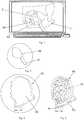
- Figs. 1 - 4illustrate an embodiment of the method for manufacturing an auxiliary device 40 to be used for the subsequent manufacture of a patient customized implant 50 ( Fig. 5 ), wherein the method comprises the steps of:
- Fig. 5illustrates an embodiment of the method for the treatment of orbital defects by using the patient customized implant 50.
- the implant 50is temporarily fixed to the auxiliary device 40 (rapid prototyping device) with the auxiliary device 40 (rapid prototyping device) fitted to the borders of the defect and to the intact parts of the orbit inferior orbital rim.
- Jaquiéry et al. accuracy of orbital reconstructionis one important factor to obtain best functional outcome, but other determinants like displacement and/or atrophy of intramuscular cone fat should be considered. This requires an additional volume i.e. a spacer or spacers to be positioned onto the customized implant 50.
- Jaquiéry C., Aeppli C., Cornelius P., Palmowsky A., Kunz C., Hammer B.Reconstruction of orbital wall defects: critical review of 72 patients", Int J Oral Maxillofac Surgery 2007, Mar 36(3): 193-9, Epub 2007 Jan 22 .
- a holding extension 41integrated in the auxiliary device 40 (rapid prototyping device) as an additional design feature facilitates manual placement of the implant 50.
- the holding device 41is designed to allow a standard surgical instrument to be used, i.e. a clamp, to manually place the implant.
- the implant 50may be positioned onto the defect without the auxiliary device 40 (rapid prototyping device) or just with a part of it, e.g. just including the parts fitting to the inferior orbital rim and/or the holding extension 41. This would minimize the space required for intraoperative placement; thus be particuarly helpful in conditions with limited access and visibility.
- the recess 42 of the auxiliary device 40 (rapid prototyping device) or the implant 50 itselfmay contain design features allowing for over contouring of the implant. This design feature may be helpful for compensating loss of soft tissue volume, e.g. useful in conditions with significant soft tissue atrophy. Therefore the recess 42 of the auxiliary device 40 (rapid prototyping device) may be designed in an over contoured fashion or with a pull linkage incorporated allowing the implant 50 to be over contoured at a given site.
- additional implant materialmay be directly fixed to the implant 50 for over contouring.
- Implant fixationis preferably achieved using screw fixation, preferably by fixing the implant 50 with screws 51 near the orbital rim.
- auxiliary device 40rapid prototyping device
Landscapes
- Health & Medical Sciences (AREA)
- Engineering & Computer Science (AREA)
- Life Sciences & Earth Sciences (AREA)
- Orthopedic Medicine & Surgery (AREA)
- General Health & Medical Sciences (AREA)
- Biomedical Technology (AREA)
- Heart & Thoracic Surgery (AREA)
- Animal Behavior & Ethology (AREA)
- Public Health (AREA)
- Veterinary Medicine (AREA)
- Surgery (AREA)
- Transplantation (AREA)
- Oral & Maxillofacial Surgery (AREA)
- Vascular Medicine (AREA)
- Cardiology (AREA)
- Nuclear Medicine, Radiotherapy & Molecular Imaging (AREA)
- Medical Informatics (AREA)
- Molecular Biology (AREA)
- Robotics (AREA)
- Neurosurgery (AREA)
- Physics & Mathematics (AREA)
- Geometry (AREA)
- Manufacturing & Machinery (AREA)
- Neurology (AREA)
- Prostheses (AREA)
Description
- The invention generally relates to a method for the reconstruction of a particular anatomy. More particularly, the present invention relates to a method for manufacturing an auxiliary device suitable for the manufacture of a patient customized implant according to the preamble of claim 1, to an auxiliary device obtained by that method, to a method for manufacturing a patient customized implant using the auxiliary device obtained by that method and a further method for the reconstruction of a particular anatomy by using that patient customized implant.
- In the following an example will be given to reconstruct the particular anatomy of an orbital defect creating an auxiliary device to manufacture an orbital implant. However it is understood that the method is not exclusively applicable to the orbital region but also to other skeletal sites.
- Orbital defects typically involve the orbital floor and medial wall and induce displacement and dysfunction of orbital soft tissue. These conditions frequently result in significant enophthalmos, impaired eye motility and disturbed binocular vision. A mainstay of surgical treatment is the reconstruction of the preinjury anatomy to reestablish orbital form and function. However this is difficult to achieve especially in large sized defects located in the posterior orbit. Adequate reconstruction must be obtained at primary surgery, as secondary surgery is even more challenging. Limited access and visibility make adequate implant shaping and positioning difficult to achieve.
- Traditional surgical techniques for reconstructing orbital wall defects involve freehand contouring and positioning of alloplastic implant or bone grafts which are technically difficult and disposed to error. In the recent past pre-shaped orbital implants and intraoperative imaging and navigation techniques have been used to facilitate the surgical procedure.
- From
RU 2 164 392 SHALUMOV - However, the standard three-dimensional (3D CT) representation of the healthy side as well as of the affected side (fracture/defect) can be severely affected. In particular, this concerns the orbit where frequently fractures occur in the range of the osseous orbital floor and the medial orbital wall. Therefore, in the treatment of orbital fractures the clinical problem is encountered that preshaped orbital implants need to be intraoperatively sized and shaped so that the precise position of the orbital implant can only be defined intraoperatively.
- Document
US 2003/216669 discloses methods and compositions for producing articular repair materials and for repairing an articular surface. - It is therefore an object of the invention to provide an improved method for manufacturing an auxiliary device suitable for the manufacture of a patient customized implant.
- The invention solves the posed problem with a method for manufacturing an auxiliary device suitable for the manufacture of a patient customized implant comprising the features of claim 1, with an auxiliary device comprising the features of claim 9, with a method for manufacturing a patient customized implant comprising the features of claims 16 and with a method for the reconstruction of a particular anatomy comprising the features of claim 17.
- The advantages of the method according to the invention are to be seen that:
- the manufacture of a patient customized implant is permitted which can consist of one of a variety of biocompatible materials and permits an incorporation of a prefabricated solid matrix portion having screw holes;
- improved 3D CT reconstruction and image mirroring techniques can be used where anatomical information was lost;
- the possibility is offered to anatomically reconstruct the healthy side indirectly as well as the affected side directly by means of 3D anatomical reference data (i.e. by means of a 3D reference model, 3D mean model or 3D atlas model) to manufacture an auxiliary device for the affected site so as to facilitate the adaption of the implant (size, shape and position). Differences in size and shape between the healthy and the affected side can be technically compensated; and
- one or more spacers of a desired shape and volume can be applied to a site where it is necessary to reduce the volume, e.g. the volume of the orbit.
- The method according to the invention can be applied in the following medical fields:
- 1. field of maxillofacial/craniofacial surgery:
- reconstruction of orbital defects (orbital floor, orbital floor/medial wall defects)
- reconstruction of calvarial defects (i.e. for cranioplasty), craniofacial and maxillofacial defects
- 2. field of orthopedic trauma:
- restoration of bony defects, particularly cortical bone defects
- in combination with minimal invasive surgery approaches
- 3. field of dental surgery: reconstruction of dentoalveolar defects
- 4. spine surgery: reconstruction of defects of the spine.
- The invention particularly offers a new computerized method for manufacturing an auxiliary device (rapid prototyping device) serving as a reconstruction template allowing for facilitated implant adaption and positioning and for different implant material to be used (i.e. standard titanium implants or biodegradable and biocompatible resin). The method offers the possibility of molding a light curing or self-setting biodegradable and biocompatible resin in a template to form an implant. The method is preferably designed as an in-house workflow requiring no costly and time-consuming external manufacturing.
- In order to solve the clinical problem the present invention comprises a sequence of specific workflow steps, necessitating digitized technologies (i.e. techniques for 3D imaging, image processing and analysis) and a rapid prototyping device with specific design features incorporated that allows for shaping as well as positioning of alloplastic implants. Further on the invention comprises a workflow that allows for immediate production of customized alloplastic implants like titanium or even of light curing or self-setting biodegradable and biocompatible resin.
- Advantages are seen, e.g. in the primary reconstruction of orbital defects. The computerized method leads to the production of an auxiliary device (reconstruction and positioning template) providing information on an individual implant geometry and on its proper positioning within the orbit. The method according to the invention allows for more efficient implant adaption and does not require repeated checks at the patient site while shaping the implant. It allows for immediate generation of patient specific alloplastic implants immediately available for surgery. There is the choice to produce customized alloplastic implants made out of titanium or of light curing or self-setting biodegradable and biocompatible resin. The use of light curing or self-setting biodegradable and biocompatible resin into the workflow permits for immediate production of organic/degradable implants.
- Further advantageous embodiments of the invention can be commented as follows:
In a special embodiment the computer template comprises a recess positioned on a surface that is directed towards a defect site, wherein the size of the computer template is larger than the size of the recess. - In a further embodiment the size of the recess is larger than the size of the defect site so as to encompass the shape of a defect.
- Preferably, the 3D generic reference data comprise a 3D anatomic atlas and/or the 3D generic reference data is obtained by mirror imaging of the healthy contralateral side and/or the 3D generic reference data comprise a 3D mean shape model, preferably with standard deviation information.
- In another embodiment the auxiliary device corresponds to a physical model of the computer template.
- In another embodiment the 3D printing technology is a rapid prototyping technology.
- In again another embodiment the auxiliary device is designed to be fitted to an unaffected region.
- In a further embodiment the auxiliary device is designed to be fitted to the boundaries of the defect and to the respective anatomical shape in this inferior orbital rim region.
- In a further embodiment the auxiliary device is designed with a holding extension facilitating manual implantation of the implant.
- In another embodiment the auxiliary device has a peripheral projection to be fitted to an unaffected region.
- In another embodiment of the auxiliary device the holding extension is designed to allow a standard surgical instrument to be used to manually position the implant.
- In yet another embodiment the auxiliary device has a recess suitable to shape and size an implant. This configuration permits the advantage that the auxiliary device can be used as a reconstruction template. This reconstruction template can be used as a mold for the manufacture of an implant (curable biocompatible resin) or as a form allowing for facilitated implant adaption (standard titanium mesh). The auxiliary device therefore permits the manufacture of a patient customized implant which can consist of one of a variety of biocompatible materials and permits an incorporation of a prefabricated solid matrix portion having screw holes.
- According to a further aspect of the invention, there is provided a method for manufacturing a patient customized implant using the auxiliary device and comprising the step of: a) introducing a curable biocompatible resin in the recess of the auxiliary device in a moldable state and photocuring the resin once fitted into the recess of the auxiliary device; OR b) press-fitting a standard implant material like a meshed titanium implant into the recess of the auxiliary device.
- In accordance with another aspect, a method for the reconstruction of a particular anatomy by using a patient customized implant is provided, the method comprising the additional step of: positioning the implant onto the defect without the auxiliary device; or positioning the implant with a least a part of the auxiliary device.
- In a special embodiment of the method the implant is positioned in the recess of the auxiliary device during implantation.
- In a further embodiment the method is characterized by the further step of fixing the implant with screws to a patient's anatomy.
- In another embodiment the auxiliary device has a peripheral projection to be fitted to an unaffected region and the part of the auxiliary device used for positioning the implant includes the peripheral projection.
- In another embodiment the auxiliary device includes a holding extension and the part of the auxiliary device used for positioning the implant includes the holding extension.
- In again another embodiment the method comprises the additional step of: removing the auxiliary device.
- A special embodiment of the invention will be described in the following by way of example and with reference to the accompanying drawings in which:
Fig. 1 illustrates a 3D computer model (based on a CT) of an orbital floor defect together with a computer template of the auxiliary device covering the orbital floor defect according to an embodiment of the invention;Fig. 2 illustrates a magnified view of the computer template offig. 1 ;Fig. 3 illustrates the computer template offig. 1 in a view onto the surface of the template which is directed to the orbital defect and which includes a recess;Fig. 4 illustrates an auxiliary device (physical model) based on the computer template offigs. 1 to 3 wherein the recess is containing an implant; andFig. 5 illustrates the implant once implanted into the orbit to be treated.Figs. 1 - 4 illustrate an embodiment of the method for manufacturing anauxiliary device 40 to be used for the subsequent manufacture of a patient customized implant 50 (Fig. 5 ), wherein the method comprises the steps of:- 1) Obtaining a pre-operative standard CT of the affected site and of the healthy contralateral side.
- 2) Based on preoperative CT and image processing techniques a computer model of the defect site and the respective healthy contralateral site is created. A main technical problem is that the 3D reconstruction process creates pseudo holes mainly due to partial volume averaging with missing anatomical information at the healthy contralateral side as well as at the affected side, i.e. in the orbit mainly located in the orbital floor and the medial wall.
- 3) The
defect site 2 is virtually reconstructed, preferably in an automated way with the preinjury anatomy integrated in an orbital computer model. This step requires anatomical information (i.e. a 3D reference model, a 3D mean model or a 3D atlas model to be used). The virtual reconstruction of the defect site can be performed by the following substeps:- A1) automated reconstruction of the healthy contralateral side using 3D anatomical reference data;
- A2) mirror imaging of the reconstructed healthy contralateral side; and
- A3) automated reconstruction of the affected side by superposing the mirror imaged reconstructed healthy contralateral side and the affected side one above another resulting in the 3D computer model with the virtually reconstructed defect side;
- B1) automated reconstruction of the healthy contralateral side according to defined landmarks on both sides and extrapolate deviation;
- B2) mirror imaging of the reconstructed healthy contralateral side; and
- B3) restoration of the affected side by superposing the mirror imaged reconstructed healthy contralateral side and the affected side one above another resulting in the 3D computer model with the virtually reconstructed defect side;
- C1) automated reconstruction of the affected side according to defined landmarks and extrapolate deviation; or
- C2) automated reconstruction of the affected side using 3D anatomical reference data; and
- C3) restoration of the affected side resulting in the 3D computer model with the virtually reconstructed defect side.
- 4) Planning and designing of the 3D implant model using the computer.
- 5) Approval of the designed 3D implant model by the surgeon:
- If the design is approved the procedure proceeds with step 6)
- If the design is not approved step 3 is repeated with alternative options B1 - B3 or C1 - C3 or with combinations of the options A1 - A3, B1 - B3 and C1 - C3.
- 6) A computer template 30 (
Fig. 1 - 3 ) is generated with preferably the following design features incorporated:
Thecomputer template 30 is:- (i) covering the
defect 2 with anoverlay 32, - (ii) designed with a
recess 35, wherein:- the
recess 35 is positioned in the surface which is directed to the orbital defect (Fig. 3 ), and - the
recess 35 is larger than the defect and encompasses the shape of the defect, so that the size of thecomputer template 30 is larger than the size of therecess 35 which in turn is larger than the defect size.
- the
- (iii) fitted to an unaffected region (i.e. to the boundaries of the defect and to the inferior orbital rim region), and
- (iv) designed with a holding
extension 31.
- (i) covering the
- 7) The auxiliary device 40 (physical model) of the
computer template 30 is manufactured using 3D printing technologies (i.e. rapid prototyping technologies). The so producedauxiliary device 40 has a shape and size that is larger than the defect size and includes arecess 42 as defined by therecess 35 of thecomputer template 30, so that therecess 42 of theauxiliary device 40 permits to adapt the size and shape of a titanium mesh which covers the defect.
Furthermore, theauxiliary device 40 can be provided with a peripheral projection the shape and size of which is defined by theoverlay 32 of thecomputer template 30 and which is suitable to be fitted to an unaffected region in the area of the affected region, i.e. with a peripheral projection that is slightly bigger than the defect to be able to design a recess and to achieve reliable positioning within the orbit. Additionally or alternatively, theauxiliary device 40 can include a holdingextension 41 which corresponds to the holdingextension 31 of thecomputer template 30 and which is suitable for positioning animplant 50. Since therecess 42 is larger than the defect and since it can be provided with a peripheral projection (i.e. designed as margin), it allows the implant to be sized, shaped and directly positioned onto the defect or allows the adapted implant together with its auxiliary device to be positioned onto the defect. Hence a recess allows an implant to be sized and shaped. A larger recess and a peripheral projection are specific design features to shape, size and position an implant, or to shape, size and position an implant together with the corresponding auxiliary device.
Theauxiliary device 40 is preferably manufactured in plastic. The production location is preferably the hospital site as this requires no external third party service to be used. The auxiliary device 40 (resulting rapid prototyping device) may be used to adjust theimplant 50 prior to or during surgery.Figs. 4 and5 illustrate an embodiment of the method for manufacturing a patient customizedimplant 50 using theauxiliary device 40 comprising the following alternative steps: - 8) Biodegradable and biocompatible resin, or alternatively a standard implant material like a meshed titanium implant is positioned in the
recess 42 of theauxiliary device 40 and shaped according to the form given by the recess 42 (Fig. 4 ).- a) In case of using abiodegradable and biocompatible resin, it is preferably available in a semi solid, moldable state when starting the implant contouring process. The material is fitted into the
recess 42 of theauxiliary device 40 and transferred to a solid state after having accomplished the implant contouring process. The change of the physical state could be achieved using a photocuring composition (e.g. methacrylated organic oligomers) or through soaking and leaching out of a biocompatible solvent (e.g. N-methyl-2-pyrrolidone) and precipitation of a polymeric composition insoluble in water. Before application the resin material is preferably available as a semi rigid matrix sheet. In case of using a photocuring composition the matrix sheet is preferably covered by non-light-transmissive lamination sheets to allow for its storage in a semi-rigid state. A prefabricated solid matrix portion with screw holes incorporated may be connected to the moldable part. The prefabricated portion allows for screw fixation near the orbital rim. - b) In case of using astandard titanium mesh preferably a cutter is used to adapt the implant boundaries according to the borders of the
recess 42 in theauxiliary device 40 defined by theinlay 35 of thecomputer template 30. Shape adaption is preferably achieved through press fitting theimplant 50 to the bottom of therecess 42 of theauxiliary device 40. In a further embodiment of the invention a second auxiliary device 40' (rapid prototyping device) may be manufactured and temporarily fixed to the first auxiliary device 40 (rapid prototyping device). Hence a thicker, reinforced construct is available when the implant manufacturing/adjustment is in progress.
- a) In case of using abiodegradable and biocompatible resin, it is preferably available in a semi solid, moldable state when starting the implant contouring process. The material is fitted into the
Fig. 5 illustrates an embodiment of the method for the treatment of orbital defects by using the patient customizedimplant 50. During intraoperative placement (Fig. 5 ) theimplant 50 is temporarily fixed to the auxiliary device 40 (rapid prototyping device) with the auxiliary device 40 (rapid prototyping device) fitted to the borders of the defect and to the intact parts of the orbit inferior orbital rim.- According to Jaquiéry et al. accuracy of orbital reconstruction is one important factor to obtain best functional outcome, but other determinants like displacement and/or atrophy of intramuscular cone fat should be considered. This requires an additional volume i.e. a spacer or spacers to be positioned onto the customized
implant 50.
Jaquiéry C., Aeppli C., Cornelius P., Palmowsky A., Kunz C., Hammer B. "Reconstruction of orbital wall defects: critical review of 72 patients", Int J Oral Maxillofac Surgery 2007, Mar 36(3): 193-9, Epub 2007 Jan 22. - In a further embodiment a holding
extension 41, integrated in the auxiliary device 40 (rapid prototyping device) as an additional design feature facilitates manual placement of theimplant 50. The holdingdevice 41 is designed to allow a standard surgical instrument to be used, i.e. a clamp, to manually place the implant. - In another embodiment of the invention the
implant 50 may be positioned onto the defect without the auxiliary device 40 (rapid prototyping device) or just with a part of it, e.g. just including the parts fitting to the inferior orbital rim and/or the holdingextension 41. This would minimize the space required for intraoperative placement; thus be particuarly helpful in conditions with limited access and visibility. - In a further embodiment of the invention the
recess 42 of the auxiliary device 40 (rapid prototyping device) or theimplant 50 itself may contain design features allowing for over contouring of the implant. This design feature may be helpful for compensating loss of soft tissue volume, e.g. useful in conditions with significant soft tissue atrophy. Therefore therecess 42 of the auxiliary device 40 (rapid prototyping device) may be designed in an over contoured fashion or with a pull linkage incorporated allowing theimplant 50 to be over contoured at a given site. - Alternatively, additional implant material may be directly fixed to the
implant 50 for over contouring. - Implant fixation is preferably achieved using screw fixation, preferably by fixing the
implant 50 withscrews 51 near the orbital rim. - Following implant placement and fixation the auxiliary device 40 (rapid prototyping device) is detached and removed.
- Although the invention has been described in conjunction with specific embodiments thereof, it is evident that many alternatives, modifications and variations will be apparent to those skilled in the art. Accordingly, it is intended to embrace all such alternatives, modifications and variations that fall within the scope of the appended claims.
Claims (11)
- Method for manufacturing an auxiliary device suitable for the manufacture of a patient customized implant comprising the steps of:1) obtaining 3D image data, preferably a CT, of a defect site of a patient's anatomy (1);2) generating a computer model of the defect site based on the 3D image data obtained in step 1 and 3D generic reference data and by using image processing techniques;3) virtually reconstructing the defect site and designing the patient customized implant;characterized by the steps of:4) generating a computer template (30) by using the computer model generated in step 2, wherein the computer template (30)(i) covers the virtually reconstructed defect site with an overlay (32) which defines the shape and size of a peripheral projection of the auxiliary device (40) that is slightly bigger than the virtually reconstructed defect site and which is suitable to be fitted to an unaffected region in the area of the defect site; and(ii) comprises a recess (35) positioned on a surface that is directed towards the virtually reconstructed defect site and wherein the recess (35) spans the virtually reconstructed defect site and wherein the size of the recess is larger than the size of the virtually reconstructed defect site so as to encompass the shape of the defect site in order to shape and size an implant (50); and5) manufacturing the auxiliary device (40) specified by the computer template (30) generated in step 4 using 3D printing.
- Method according to claim 1,characterized in that the 3D generic reference data comprise a 3D anatomic atlas.
- Method according to one of the claims 1 to 2,characterized in that the 3D generic reference data is obtained by mirror imaging of the healthy contralateral side.
- Method according to one of the claims 1 to 3,characterized in that the 3D generic reference data comprise a 3D mean shape model, preferably with standard deviation information.
- Method according to one of the claims 1 to 4,characterized in that the auxiliary device (40) corresponds to a physical model of the computer template (30).
- Method according to one of the claims 1 to 5,characterized in that the 3D printing technology is a rapid prototyping technology.
- Auxiliary device (40) obtained by the method according to one of the claims 1 to 6,
- Auxiliary device according to claim 7,characterized in that it is designed with a holding extension (41) facilitating manual implantation of the implant (50).
- Auxiliary device according to claim 7 or 8,characterized in that it comprises a peripheral projection to be fitted to an unaffected region.
- Auxiliary device according to one of the claims 7 to 9,characterized in that it comprises a recess (42) suitable to shape and size an implant (50).
- Method for manufacturing a patient customized implant using the auxiliary device obtained by the method according to one of the claims 1 to 6 and comprising the step of:a) introducing a curable biocompatible resin in the recess (42) of the auxiliary device (40) in a moldable state and photocuring the resin once fitted into the recess (42) of the auxiliary device (40); ORb) press-fitting a standard implant material like a meshed titanium implant into the recess (42) of the auxiliary device (40).
Applications Claiming Priority (1)
| Application Number | Priority Date | Filing Date | Title |
|---|---|---|---|
| PCT/CH2015/000001WO2016112469A1 (en) | 2015-01-12 | 2015-01-12 | Method for manufacturing an auxiliary device suitable for the manufacture of a patient customized implant |
Publications (2)
| Publication Number | Publication Date |
|---|---|
| EP3244835A1 EP3244835A1 (en) | 2017-11-22 |
| EP3244835B1true EP3244835B1 (en) | 2021-09-15 |
Family
ID=52394019
Family Applications (1)
| Application Number | Title | Priority Date | Filing Date |
|---|---|---|---|
| EP15700838.4AActiveEP3244835B1 (en) | 2015-01-12 | 2015-01-12 | Method for manufacturing an auxiliary device suitable for the manufacture of a patient customized implant |
Country Status (5)
| Country | Link |
|---|---|
| US (1) | US10512546B2 (en) |
| EP (1) | EP3244835B1 (en) |
| JP (1) | JP6527233B2 (en) |
| CA (1) | CA2971005C (en) |
| WO (1) | WO2016112469A1 (en) |
Families Citing this family (33)
| Publication number | Priority date | Publication date | Assignee | Title |
|---|---|---|---|---|
| EP3244835B1 (en)* | 2015-01-12 | 2021-09-15 | AO Technology AG | Method for manufacturing an auxiliary device suitable for the manufacture of a patient customized implant |
| WO2017010811A1 (en)* | 2015-07-13 | 2017-01-19 | 한양대학교 산학협력단 | Personalized alveolar bone tissue and method for manufacturing same |
| GR1009414B (en)* | 2016-12-30 | 2018-12-14 | Δημητριος Χριστοφορου Τζοκας | Method for the production of a mould with a three-dimensional printing preform |
| IT201700015032A1 (en)* | 2017-02-10 | 2018-08-10 | Shoulder App S R L | System for making a portion of bone corresponding to a portion of missing bone. |
| US11033333B2 (en) | 2017-04-06 | 2021-06-15 | Stryker European Holdings I, Llc | Plate selection user interface and design tool with database |
| EP3424452B1 (en) | 2017-06-16 | 2024-03-13 | Stryker European Operations Holdings LLC | Patient-specific bridging plates |
| US11166764B2 (en) | 2017-07-27 | 2021-11-09 | Carlsmed, Inc. | Systems and methods for assisting and augmenting surgical procedures |
| CN107374785B (en)* | 2017-08-02 | 2019-04-05 | 吉林大学 | A kind of pre- production method of orbital blow-out fracture titanium net |
| US11476007B2 (en)* | 2017-09-22 | 2022-10-18 | Xo Care A/S | Information and data logging system for use in a dental environment |
| CN107616839A (en)* | 2017-11-10 | 2018-01-23 | 岳春华 | A kind of flap perforating artery localization method rebuild based on 3D printing |
| US11083586B2 (en) | 2017-12-04 | 2021-08-10 | Carlsmed, Inc. | Systems and methods for multi-planar orthopedic alignment |
| KR102028818B1 (en)* | 2018-01-12 | 2019-10-04 | 애니메디솔루션 주식회사 | Orbital implant for treatment of orbital wall fracture, customized mold for making the orbital implant, method for manufacturing the customized mold, and method for manufacturing the orbital implant |
| US11432943B2 (en) | 2018-03-14 | 2022-09-06 | Carlsmed, Inc. | Systems and methods for orthopedic implant fixation |
| US11439514B2 (en) | 2018-04-16 | 2022-09-13 | Carlsmed, Inc. | Systems and methods for orthopedic implant fixation |
| USD958151S1 (en) | 2018-07-30 | 2022-07-19 | Carlsmed, Inc. | Display screen with a graphical user interface for surgical planning |
| WO2020056186A1 (en) | 2018-09-12 | 2020-03-19 | Carlsmed, Inc. | Systems and methods for orthopedic implants |
| US10849665B2 (en) | 2018-10-29 | 2020-12-01 | Stryker European Operations Holdings Llc | Snap-fit cutting guides and plating systems |
| EP3888095A4 (en) | 2018-11-29 | 2022-08-31 | Carlsmed, Inc. | SYSTEMS AND PROCEDURES FOR ORTHOPEDIC IMPLANTS |
| US10902944B1 (en) | 2020-01-06 | 2021-01-26 | Carlsmed, Inc. | Patient-specific medical procedures and devices, and associated systems and methods |
| US11376076B2 (en) | 2020-01-06 | 2022-07-05 | Carlsmed, Inc. | Patient-specific medical systems, devices, and methods |
| EP4110233A4 (en)* | 2020-02-24 | 2024-03-20 | Acumed LLC | Craniofacial implants for neuroplastic surgery |
| US12232965B2 (en)* | 2020-07-29 | 2025-02-25 | DePuy Synthes Products, Inc. | Patient specific graft cage for craniomaxillofacial repair |
| US12226315B2 (en) | 2020-08-06 | 2025-02-18 | Carlsmed, Inc. | Kinematic data-based patient-specific artificial discs, implants and associated systems and methods |
| WO2022109259A1 (en) | 2020-11-20 | 2022-05-27 | Carlsmed, Inc. | Patient-specific jig for personalized surgery |
| US12232980B2 (en) | 2021-06-08 | 2025-02-25 | Carlsmed, Inc. | Patient-specific expandable spinal implants and associated systems and methods |
| EP4351474A4 (en)* | 2021-06-08 | 2025-05-21 | Meticuly Company Limited | CRANIOMAXILLOFACIAL IMPLANT AND ITS DESIGN PROCESS |
| CN113230002B (en)* | 2021-06-22 | 2024-05-14 | 安阳市第六人民医院(安阳市口腔医院) | Preparation method of personalized titanium mesh for bone defect reconstruction of dental implant area |
| CN113576639B (en)* | 2021-08-25 | 2023-11-21 | 北京大学第三医院(北京大学第三临床医学院) | An auxiliary plate for reconstruction of the posterior wall of the sacral canal and its use method |
| CN113768667B (en)* | 2021-09-08 | 2023-05-05 | 佳木斯大学 | Preparation method of 3D printing bionic structure titanium mesh based on personalized design |
| JP2024542048A (en) | 2021-11-01 | 2024-11-13 | カールスメッド インコーポレイテッド | Reduced Subsidence Spinal Implants and Surgical Procedures, and Related Systems and Methods - Patent application |
| US11443838B1 (en) | 2022-02-23 | 2022-09-13 | Carlsmed, Inc. | Non-fungible token systems and methods for storing and accessing healthcare data |
| US11806241B1 (en) | 2022-09-22 | 2023-11-07 | Carlsmed, Inc. | System for manufacturing and pre-operative inspecting of patient-specific implants |
| US11793577B1 (en) | 2023-01-27 | 2023-10-24 | Carlsmed, Inc. | Techniques to map three-dimensional human anatomy data to two-dimensional human anatomy data |
Family Cites Families (11)
| Publication number | Priority date | Publication date | Assignee | Title |
|---|---|---|---|---|
| US7468075B2 (en)* | 2001-05-25 | 2008-12-23 | Conformis, Inc. | Methods and compositions for articular repair |
| RU2164392C1 (en) | 2000-06-27 | 2001-03-27 | Шалумов Арнольд-Суруиль Зироевич | Method for producing individual high precision implant for compensating complex subtotal polyosseous orbital cavity defect |
| CN105030296A (en)* | 2006-02-06 | 2015-11-11 | 康复米斯公司 | Patient selectable joint arthroplasty devices and surgical tools |
| US8265949B2 (en)* | 2007-09-27 | 2012-09-11 | Depuy Products, Inc. | Customized patient surgical plan |
| US11039889B2 (en)* | 2010-06-29 | 2021-06-22 | Mighty Oak Medical, Inc. | Patient-matched apparatus and methods for performing surgical procedures |
| KR20120088928A (en)* | 2011-02-01 | 2012-08-09 | 고려대학교 산학협력단 | Method for manufacturing customized skull implant applied to cranioplasty |
| US9241772B2 (en) | 2011-03-17 | 2016-01-26 | Brainlab Ag | Method for preparing the reconstruction of a damaged bone structure |
| CA2834937A1 (en)* | 2011-05-03 | 2012-11-08 | Smith & Nephew, Inc. | Patient-matched guides for orthopedic implants |
| US20160346091A1 (en) | 2013-04-30 | 2016-12-01 | Universiti Malaya | A method for manufacturing a customized implant |
| ES2987433T3 (en)* | 2014-04-14 | 2024-11-14 | Lima Usa Inc | Kinematic alignment and novel femoral and tibial prosthesis |
| EP3244835B1 (en)* | 2015-01-12 | 2021-09-15 | AO Technology AG | Method for manufacturing an auxiliary device suitable for the manufacture of a patient customized implant |
- 2015
- 2015-01-12EPEP15700838.4Apatent/EP3244835B1/enactiveActive
- 2015-01-12USUS15/542,476patent/US10512546B2/enactiveActive
- 2015-01-12JPJP2017536793Apatent/JP6527233B2/enactiveActive
- 2015-01-12CACA2971005Apatent/CA2971005C/enactiveActive
- 2015-01-12WOPCT/CH2015/000001patent/WO2016112469A1/ennot_activeCeased
Also Published As
| Publication number | Publication date |
|---|---|
| US20180271661A1 (en) | 2018-09-27 |
| JP2018501897A (en) | 2018-01-25 |
| CA2971005C (en) | 2022-08-16 |
| EP3244835A1 (en) | 2017-11-22 |
| JP6527233B2 (en) | 2019-06-05 |
| CA2971005A1 (en) | 2016-07-21 |
| WO2016112469A1 (en) | 2016-07-21 |
| US10512546B2 (en) | 2019-12-24 |
Similar Documents
| Publication | Publication Date | Title |
|---|---|---|
| EP3244835B1 (en) | Method for manufacturing an auxiliary device suitable for the manufacture of a patient customized implant | |
| US8706285B2 (en) | Process to design and fabricate a custom-fit implant | |
| Walch et al. | Three-dimensional planning and use of patient-specific guides improve glenoid component position: an in vitro study | |
| Wong et al. | One-step reconstruction with a 3D-printed, biomechanically evaluated custom implant after complex pelvic tumor resection | |
| US11701230B2 (en) | Patient-specific mandibular implant inserted into mandibular defect region and method of manufacturing the same | |
| JP6362592B2 (en) | Method for operating a graphical 3D computer model of at least one anatomical structure with selectable preoperative, intraoperative or postoperative status | |
| Dahake et al. | Applications of medical rapid prototyping assisted customized surgical guides in complex surgeries | |
| US12268403B2 (en) | Surgical guides with removable inserts | |
| Hatamleh et al. | Simultaneous computer-aided design/computer-aided manufacture bimaxillary orthognathic surgery and mandibular reconstruction using selective-laser sintered titanium implant | |
| Sherekar et al. | Application of biomodels for surgical planning by using rapid prototyping: a review and case studies | |
| Christensen et al. | The digital thread for personalized craniomaxillofacial surgery | |
| Orzell et al. | Secondary repair of the zygoma | |
| Żukowska et al. | Rapid manufacturing of individualized supplies for eye socket reconstructive surgery | |
| Neamah et al. | Design and manufacturing of custom 3D printed bone implants | |
| Huang et al. | Three-dimensional digital technology: a powerful assistant for the reconstruction of complex craniofacial deformities | |
| EP3979933B1 (en) | Support for an anatomical structure | |
| Malyala et al. | Benefits of additive manufacturing medical model in orbital floor reconstruction surgery: a case study | |
| Alawy et al. | The virtual surgery to reconstruct the mandible using digital images | |
| Eggbeer | Computational design of biostructures | |
| Beaudreau et al. | The Digital Thread for Personalized Craniomaxillofacial Surgery | |
| Maglione et al. | Orbital floor reconstruction in facial asymmetry: a clinical case | |
| Neamah et al. | Additive Manufacturing of Custom Orthopedic Implants: A Review | |
| Rosique | Surgical Planning in Shoulder Prostheses with 3D Reconstruction and Customized 3D Guides | |
| Fusetti et al. | 3D Facial Prosthesis | |
| Harryson et al. | Application of SFF to preoperative planning and surgical rehearsal for treatment of limb deformities in dogs |
Legal Events
| Date | Code | Title | Description |
|---|---|---|---|
| STAA | Information on the status of an ep patent application or granted ep patent | Free format text:STATUS: THE INTERNATIONAL PUBLICATION HAS BEEN MADE | |
| PUAI | Public reference made under article 153(3) epc to a published international application that has entered the european phase | Free format text:ORIGINAL CODE: 0009012 | |
| STAA | Information on the status of an ep patent application or granted ep patent | Free format text:STATUS: REQUEST FOR EXAMINATION WAS MADE | |
| 17P | Request for examination filed | Effective date:20170612 | |
| AK | Designated contracting states | Kind code of ref document:A1 Designated state(s):AL AT BE BG CH CY CZ DE DK EE ES FI FR GB GR HR HU IE IS IT LI LT LU LV MC MK MT NL NO PL PT RO RS SE SI SK SM TR | |
| AX | Request for extension of the european patent | Extension state:BA ME | |
| DAX | Request for extension of the european patent (deleted) | ||
| GRAP | Despatch of communication of intention to grant a patent | Free format text:ORIGINAL CODE: EPIDOSNIGR1 | |
| STAA | Information on the status of an ep patent application or granted ep patent | Free format text:STATUS: GRANT OF PATENT IS INTENDED | |
| INTG | Intention to grant announced | Effective date:20210407 | |
| RIN1 | Information on inventor provided before grant (corrected) | Inventor name:EGLIN, DAVID Inventor name:KAMER, LUKAS | |
| GRAS | Grant fee paid | Free format text:ORIGINAL CODE: EPIDOSNIGR3 | |
| GRAA | (expected) grant | Free format text:ORIGINAL CODE: 0009210 | |
| STAA | Information on the status of an ep patent application or granted ep patent | Free format text:STATUS: THE PATENT HAS BEEN GRANTED | |
| AK | Designated contracting states | Kind code of ref document:B1 Designated state(s):AL AT BE BG CH CY CZ DE DK EE ES FI FR GB GR HR HU IE IS IT LI LT LU LV MC MK MT NL NO PL PT RO RS SE SI SK SM TR | |
| REG | Reference to a national code | Ref country code:GB Ref legal event code:FG4D Ref country code:CH Ref legal event code:EP | |
| REG | Reference to a national code | Ref country code:DE Ref legal event code:R096 Ref document number:602015073273 Country of ref document:DE | |
| REG | Reference to a national code | Ref country code:IE Ref legal event code:FG4D | |
| REG | Reference to a national code | Ref country code:AT Ref legal event code:REF Ref document number:1429952 Country of ref document:AT Kind code of ref document:T Effective date:20211015 | |
| REG | Reference to a national code | Ref country code:LT Ref legal event code:MG9D | |
| REG | Reference to a national code | Ref country code:NL Ref legal event code:MP Effective date:20210915 | |
| PG25 | Lapsed in a contracting state [announced via postgrant information from national office to epo] | Ref country code:SE Free format text:LAPSE BECAUSE OF FAILURE TO SUBMIT A TRANSLATION OF THE DESCRIPTION OR TO PAY THE FEE WITHIN THE PRESCRIBED TIME-LIMIT Effective date:20210915 Ref country code:RS Free format text:LAPSE BECAUSE OF FAILURE TO SUBMIT A TRANSLATION OF THE DESCRIPTION OR TO PAY THE FEE WITHIN THE PRESCRIBED TIME-LIMIT Effective date:20210915 Ref country code:HR Free format text:LAPSE BECAUSE OF FAILURE TO SUBMIT A TRANSLATION OF THE DESCRIPTION OR TO PAY THE FEE WITHIN THE PRESCRIBED TIME-LIMIT Effective date:20210915 Ref country code:LT Free format text:LAPSE BECAUSE OF FAILURE TO SUBMIT A TRANSLATION OF THE DESCRIPTION OR TO PAY THE FEE WITHIN THE PRESCRIBED TIME-LIMIT Effective date:20210915 Ref country code:BG Free format text:LAPSE BECAUSE OF FAILURE TO SUBMIT A TRANSLATION OF THE DESCRIPTION OR TO PAY THE FEE WITHIN THE PRESCRIBED TIME-LIMIT Effective date:20211215 Ref country code:FI Free format text:LAPSE BECAUSE OF FAILURE TO SUBMIT A TRANSLATION OF THE DESCRIPTION OR TO PAY THE FEE WITHIN THE PRESCRIBED TIME-LIMIT Effective date:20210915 Ref country code:NO Free format text:LAPSE BECAUSE OF FAILURE TO SUBMIT A TRANSLATION OF THE DESCRIPTION OR TO PAY THE FEE WITHIN THE PRESCRIBED TIME-LIMIT Effective date:20211215 | |
| REG | Reference to a national code | Ref country code:AT Ref legal event code:MK05 Ref document number:1429952 Country of ref document:AT Kind code of ref document:T Effective date:20210915 | |
| PG25 | Lapsed in a contracting state [announced via postgrant information from national office to epo] | Ref country code:LV Free format text:LAPSE BECAUSE OF FAILURE TO SUBMIT A TRANSLATION OF THE DESCRIPTION OR TO PAY THE FEE WITHIN THE PRESCRIBED TIME-LIMIT Effective date:20210915 Ref country code:GR Free format text:LAPSE BECAUSE OF FAILURE TO SUBMIT A TRANSLATION OF THE DESCRIPTION OR TO PAY THE FEE WITHIN THE PRESCRIBED TIME-LIMIT Effective date:20211216 | |
| PG25 | Lapsed in a contracting state [announced via postgrant information from national office to epo] | Ref country code:AT Free format text:LAPSE BECAUSE OF FAILURE TO SUBMIT A TRANSLATION OF THE DESCRIPTION OR TO PAY THE FEE WITHIN THE PRESCRIBED TIME-LIMIT Effective date:20210915 | |
| PG25 | Lapsed in a contracting state [announced via postgrant information from national office to epo] | Ref country code:IS Free format text:LAPSE BECAUSE OF FAILURE TO SUBMIT A TRANSLATION OF THE DESCRIPTION OR TO PAY THE FEE WITHIN THE PRESCRIBED TIME-LIMIT Effective date:20220115 Ref country code:SM Free format text:LAPSE BECAUSE OF FAILURE TO SUBMIT A TRANSLATION OF THE DESCRIPTION OR TO PAY THE FEE WITHIN THE PRESCRIBED TIME-LIMIT Effective date:20210915 Ref country code:SK Free format text:LAPSE BECAUSE OF FAILURE TO SUBMIT A TRANSLATION OF THE DESCRIPTION OR TO PAY THE FEE WITHIN THE PRESCRIBED TIME-LIMIT Effective date:20210915 Ref country code:RO Free format text:LAPSE BECAUSE OF FAILURE TO SUBMIT A TRANSLATION OF THE DESCRIPTION OR TO PAY THE FEE WITHIN THE PRESCRIBED TIME-LIMIT Effective date:20210915 Ref country code:PT Free format text:LAPSE BECAUSE OF FAILURE TO SUBMIT A TRANSLATION OF THE DESCRIPTION OR TO PAY THE FEE WITHIN THE PRESCRIBED TIME-LIMIT Effective date:20220117 Ref country code:PL Free format text:LAPSE BECAUSE OF FAILURE TO SUBMIT A TRANSLATION OF THE DESCRIPTION OR TO PAY THE FEE WITHIN THE PRESCRIBED TIME-LIMIT Effective date:20210915 Ref country code:NL Free format text:LAPSE BECAUSE OF FAILURE TO SUBMIT A TRANSLATION OF THE DESCRIPTION OR TO PAY THE FEE WITHIN THE PRESCRIBED TIME-LIMIT Effective date:20210915 Ref country code:ES Free format text:LAPSE BECAUSE OF FAILURE TO SUBMIT A TRANSLATION OF THE DESCRIPTION OR TO PAY THE FEE WITHIN THE PRESCRIBED TIME-LIMIT Effective date:20210915 Ref country code:EE Free format text:LAPSE BECAUSE OF FAILURE TO SUBMIT A TRANSLATION OF THE DESCRIPTION OR TO PAY THE FEE WITHIN THE PRESCRIBED TIME-LIMIT Effective date:20210915 Ref country code:CZ Free format text:LAPSE BECAUSE OF FAILURE TO SUBMIT A TRANSLATION OF THE DESCRIPTION OR TO PAY THE FEE WITHIN THE PRESCRIBED TIME-LIMIT Effective date:20210915 Ref country code:AL Free format text:LAPSE BECAUSE OF FAILURE TO SUBMIT A TRANSLATION OF THE DESCRIPTION OR TO PAY THE FEE WITHIN THE PRESCRIBED TIME-LIMIT Effective date:20210915 | |
| REG | Reference to a national code | Ref country code:DE Ref legal event code:R097 Ref document number:602015073273 Country of ref document:DE | |
| PLBE | No opposition filed within time limit | Free format text:ORIGINAL CODE: 0009261 | |
| STAA | Information on the status of an ep patent application or granted ep patent | Free format text:STATUS: NO OPPOSITION FILED WITHIN TIME LIMIT | |
| PG25 | Lapsed in a contracting state [announced via postgrant information from national office to epo] | Ref country code:DK Free format text:LAPSE BECAUSE OF FAILURE TO SUBMIT A TRANSLATION OF THE DESCRIPTION OR TO PAY THE FEE WITHIN THE PRESCRIBED TIME-LIMIT Effective date:20210915 | |
| 26N | No opposition filed | Effective date:20220616 | |
| PG25 | Lapsed in a contracting state [announced via postgrant information from national office to epo] | Ref country code:SI Free format text:LAPSE BECAUSE OF FAILURE TO SUBMIT A TRANSLATION OF THE DESCRIPTION OR TO PAY THE FEE WITHIN THE PRESCRIBED TIME-LIMIT Effective date:20210915 Ref country code:MC Free format text:LAPSE BECAUSE OF FAILURE TO SUBMIT A TRANSLATION OF THE DESCRIPTION OR TO PAY THE FEE WITHIN THE PRESCRIBED TIME-LIMIT Effective date:20210915 | |
| REG | Reference to a national code | Ref country code:BE Ref legal event code:MM Effective date:20220131 | |
| PG25 | Lapsed in a contracting state [announced via postgrant information from national office to epo] | Ref country code:LU Free format text:LAPSE BECAUSE OF NON-PAYMENT OF DUE FEES Effective date:20220112 | |
| PG25 | Lapsed in a contracting state [announced via postgrant information from national office to epo] | Ref country code:BE Free format text:LAPSE BECAUSE OF NON-PAYMENT OF DUE FEES Effective date:20220131 | |
| PG25 | Lapsed in a contracting state [announced via postgrant information from national office to epo] | Ref country code:IT Free format text:LAPSE BECAUSE OF FAILURE TO SUBMIT A TRANSLATION OF THE DESCRIPTION OR TO PAY THE FEE WITHIN THE PRESCRIBED TIME-LIMIT Effective date:20210915 Ref country code:IE Free format text:LAPSE BECAUSE OF NON-PAYMENT OF DUE FEES Effective date:20220112 | |
| PG25 | Lapsed in a contracting state [announced via postgrant information from national office to epo] | Ref country code:HU Free format text:LAPSE BECAUSE OF FAILURE TO SUBMIT A TRANSLATION OF THE DESCRIPTION OR TO PAY THE FEE WITHIN THE PRESCRIBED TIME-LIMIT; INVALID AB INITIO Effective date:20150112 | |
| PG25 | Lapsed in a contracting state [announced via postgrant information from national office to epo] | Ref country code:MK Free format text:LAPSE BECAUSE OF FAILURE TO SUBMIT A TRANSLATION OF THE DESCRIPTION OR TO PAY THE FEE WITHIN THE PRESCRIBED TIME-LIMIT Effective date:20210915 Ref country code:CY Free format text:LAPSE BECAUSE OF FAILURE TO SUBMIT A TRANSLATION OF THE DESCRIPTION OR TO PAY THE FEE WITHIN THE PRESCRIBED TIME-LIMIT Effective date:20210915 | |
| PG25 | Lapsed in a contracting state [announced via postgrant information from national office to epo] | Ref country code:MT Free format text:LAPSE BECAUSE OF FAILURE TO SUBMIT A TRANSLATION OF THE DESCRIPTION OR TO PAY THE FEE WITHIN THE PRESCRIBED TIME-LIMIT Effective date:20210915 | |
| PGFP | Annual fee paid to national office [announced via postgrant information from national office to epo] | Ref country code:DE Payment date:20250121 Year of fee payment:11 | |
| PGFP | Annual fee paid to national office [announced via postgrant information from national office to epo] | Ref country code:CH Payment date:20250201 Year of fee payment:11 | |
| PGFP | Annual fee paid to national office [announced via postgrant information from national office to epo] | Ref country code:FR Payment date:20250127 Year of fee payment:11 | |
| PGFP | Annual fee paid to national office [announced via postgrant information from national office to epo] | Ref country code:GB Payment date:20250128 Year of fee payment:11 |