EP3243625B1 - Medical rubber stopper and method for producing medical rubber stopper - Google Patents
Medical rubber stopper and method for producing medical rubber stopperDownload PDFInfo
- Publication number
- EP3243625B1 EP3243625B1EP17168140.6AEP17168140AEP3243625B1EP 3243625 B1EP3243625 B1EP 3243625B1EP 17168140 AEP17168140 AEP 17168140AEP 3243625 B1EP3243625 B1EP 3243625B1
- Authority
- EP
- European Patent Office
- Prior art keywords
- rubber stopper
- groove
- leg portion
- inert film
- flange region
- Prior art date
- Legal status (The legal status is an assumption and is not a legal conclusion. Google has not performed a legal analysis and makes no representation as to the accuracy of the status listed.)
- Active
Links
Images


Classifications
- B—PERFORMING OPERATIONS; TRANSPORTING
- B29—WORKING OF PLASTICS; WORKING OF SUBSTANCES IN A PLASTIC STATE IN GENERAL
- B29D—PRODUCING PARTICULAR ARTICLES FROM PLASTICS OR FROM SUBSTANCES IN A PLASTIC STATE
- B29D99/00—Subject matter not provided for in other groups of this subclass
- B29D99/0096—Producing closure members for containers, e.g. closure caps or stoppers
- A—HUMAN NECESSITIES
- A61—MEDICAL OR VETERINARY SCIENCE; HYGIENE
- A61J—CONTAINERS SPECIALLY ADAPTED FOR MEDICAL OR PHARMACEUTICAL PURPOSES; DEVICES OR METHODS SPECIALLY ADAPTED FOR BRINGING PHARMACEUTICAL PRODUCTS INTO PARTICULAR PHYSICAL OR ADMINISTERING FORMS; DEVICES FOR ADMINISTERING FOOD OR MEDICINES ORALLY; BABY COMFORTERS; DEVICES FOR RECEIVING SPITTLE
- A61J1/00—Containers specially adapted for medical or pharmaceutical purposes
- A61J1/14—Details; Accessories therefor
- A61J1/1406—Septums, pierceable membranes
- A—HUMAN NECESSITIES
- A61—MEDICAL OR VETERINARY SCIENCE; HYGIENE
- A61J—CONTAINERS SPECIALLY ADAPTED FOR MEDICAL OR PHARMACEUTICAL PURPOSES; DEVICES OR METHODS SPECIALLY ADAPTED FOR BRINGING PHARMACEUTICAL PRODUCTS INTO PARTICULAR PHYSICAL OR ADMINISTERING FORMS; DEVICES FOR ADMINISTERING FOOD OR MEDICINES ORALLY; BABY COMFORTERS; DEVICES FOR RECEIVING SPITTLE
- A61J1/00—Containers specially adapted for medical or pharmaceutical purposes
- A61J1/14—Details; Accessories therefor
- A61J1/1412—Containers with closing means, e.g. caps
- B—PERFORMING OPERATIONS; TRANSPORTING
- B29—WORKING OF PLASTICS; WORKING OF SUBSTANCES IN A PLASTIC STATE IN GENERAL
- B29C—SHAPING OR JOINING OF PLASTICS; SHAPING OF MATERIAL IN A PLASTIC STATE, NOT OTHERWISE PROVIDED FOR; AFTER-TREATMENT OF THE SHAPED PRODUCTS, e.g. REPAIRING
- B29C43/00—Compression moulding, i.e. applying external pressure to flow the moulding material; Apparatus therefor
- B29C43/02—Compression moulding, i.e. applying external pressure to flow the moulding material; Apparatus therefor of articles of definite length, i.e. discrete articles
- B29C43/18—Compression moulding, i.e. applying external pressure to flow the moulding material; Apparatus therefor of articles of definite length, i.e. discrete articles incorporating preformed parts or layers, e.g. compression moulding around inserts or for coating articles
- B29C43/183—Compression moulding, i.e. applying external pressure to flow the moulding material; Apparatus therefor of articles of definite length, i.e. discrete articles incorporating preformed parts or layers, e.g. compression moulding around inserts or for coating articles the preformed layer being a lining, e.g. shaped in the mould before compression moulding, or a preformed shell adapted to the shape of the mould
- B29C43/184—Compression moulding, i.e. applying external pressure to flow the moulding material; Apparatus therefor of articles of definite length, i.e. discrete articles incorporating preformed parts or layers, e.g. compression moulding around inserts or for coating articles the preformed layer being a lining, e.g. shaped in the mould before compression moulding, or a preformed shell adapted to the shape of the mould shaped by the compression of the material during moulding
- B—PERFORMING OPERATIONS; TRANSPORTING
- B65—CONVEYING; PACKING; STORING; HANDLING THIN OR FILAMENTARY MATERIAL
- B65D—CONTAINERS FOR STORAGE OR TRANSPORT OF ARTICLES OR MATERIALS, e.g. BAGS, BARRELS, BOTTLES, BOXES, CANS, CARTONS, CRATES, DRUMS, JARS, TANKS, HOPPERS, FORWARDING CONTAINERS; ACCESSORIES, CLOSURES, OR FITTINGS THEREFOR; PACKAGING ELEMENTS; PACKAGES
- B65D39/00—Closures arranged within necks or pouring openings or in discharge apertures, e.g. stoppers
- B65D39/0005—Closures arranged within necks or pouring openings or in discharge apertures, e.g. stoppers made in one piece
- B—PERFORMING OPERATIONS; TRANSPORTING
- B65—CONVEYING; PACKING; STORING; HANDLING THIN OR FILAMENTARY MATERIAL
- B65D—CONTAINERS FOR STORAGE OR TRANSPORT OF ARTICLES OR MATERIALS, e.g. BAGS, BARRELS, BOTTLES, BOXES, CANS, CARTONS, CRATES, DRUMS, JARS, TANKS, HOPPERS, FORWARDING CONTAINERS; ACCESSORIES, CLOSURES, OR FITTINGS THEREFOR; PACKAGING ELEMENTS; PACKAGES
- B65D51/00—Closures not otherwise provided for
- B65D51/005—Closures provided with linings or internal coatings so as to avoid contact of the closure with the contents
- B—PERFORMING OPERATIONS; TRANSPORTING
- B23—MACHINE TOOLS; METAL-WORKING NOT OTHERWISE PROVIDED FOR
- B23K—SOLDERING OR UNSOLDERING; WELDING; CLADDING OR PLATING BY SOLDERING OR WELDING; CUTTING BY APPLYING HEAT LOCALLY, e.g. FLAME CUTTING; WORKING BY LASER BEAM
- B23K26/00—Working by laser beam, e.g. welding, cutting or boring
- B23K26/36—Removing material
- B23K26/362—Laser etching
- B23K26/364—Laser etching for making a groove or trench, e.g. for scribing a break initiation groove
- B—PERFORMING OPERATIONS; TRANSPORTING
- B23—MACHINE TOOLS; METAL-WORKING NOT OTHERWISE PROVIDED FOR
- B23K—SOLDERING OR UNSOLDERING; WELDING; CLADDING OR PLATING BY SOLDERING OR WELDING; CUTTING BY APPLYING HEAT LOCALLY, e.g. FLAME CUTTING; WORKING BY LASER BEAM
- B23K26/00—Working by laser beam, e.g. welding, cutting or boring
- B23K26/36—Removing material
- B23K26/40—Removing material taking account of the properties of the material involved
- B23K26/402—Removing material taking account of the properties of the material involved involving non-metallic material, e.g. isolators
- B—PERFORMING OPERATIONS; TRANSPORTING
- B29—WORKING OF PLASTICS; WORKING OF SUBSTANCES IN A PLASTIC STATE IN GENERAL
- B29C—SHAPING OR JOINING OF PLASTICS; SHAPING OF MATERIAL IN A PLASTIC STATE, NOT OTHERWISE PROVIDED FOR; AFTER-TREATMENT OF THE SHAPED PRODUCTS, e.g. REPAIRING
- B29C2793/00—Shaping techniques involving a cutting or machining operation
- B29C2793/009—Shaping techniques involving a cutting or machining operation after shaping
- B—PERFORMING OPERATIONS; TRANSPORTING
- B29—WORKING OF PLASTICS; WORKING OF SUBSTANCES IN A PLASTIC STATE IN GENERAL
- B29L—INDEXING SCHEME ASSOCIATED WITH SUBCLASS B29C, RELATING TO PARTICULAR ARTICLES
- B29L2031/00—Other particular articles
- B29L2031/56—Stoppers or lids for bottles, jars, or the like, e.g. closures
- B29L2031/565—Stoppers or lids for bottles, jars, or the like, e.g. closures for containers
- B—PERFORMING OPERATIONS; TRANSPORTING
- B29—WORKING OF PLASTICS; WORKING OF SUBSTANCES IN A PLASTIC STATE IN GENERAL
- B29L—INDEXING SCHEME ASSOCIATED WITH SUBCLASS B29C, RELATING TO PARTICULAR ARTICLES
- B29L2031/00—Other particular articles
- B29L2031/753—Medical equipment; Accessories therefor
Definitions
- the present inventionrelates to a medical rubber stopper and a method for producing a medical rubber stopper.
- the features of the preamble of the independent claimsare known from GB 2 106 084 A .
- Related technologyis known from EP 2 998 237 A1 .
- the quality stability of drugs in vialshas been improved by laminating the leg portion of a rubber stopper, which is to be in contact with drugs, with an inert film, such as of fluororesin, to improve the chemical resistance of the rubber stopper.
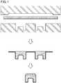
- Known lamination methodsinclude two-step molding processes (see Figs. 1 and 2 , and Patent Literature 1) and one-step molding processes (see Fig. 3 ).
- Rubber stoppers produced by two-step molding processesare excellent in airtightness as the lower surface of their flange region and the base of their leg portion are provided as a rubber surface.
- the two-step molding processeshave a problem in that a molding step and a step of removing unnecessary parts both need to be performed twice, thereby resulting in poor productivity.
- Another problemis that oily preparations may reach the rubber surface to swell the rubber, thereby resulting in poor chemical resistance and airtightness.
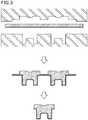
- one-step molding processescan produce rubber stoppers whose flange region has a lower surface entirely laminated with an inert film, and are also excellent in productivity as the number of steps is greatly smaller than that of the two-step molding processes.
- the airtightness of a vialcan be achieved, for example, by bringing the inner wall and the upper surface of the vial into intimate pressure contact with the base of the leg portion and the lower surface of the flange region of a rubber stopper.
- rubber stoppers produced by the one-step molding processeshave poor airtightness because each of the above contact surfaces is hard glass or an inert film.
- Patent Literature 1JP 2004-216753 A
- the present inventionaims to provide a medical rubber stopper that is excellent in chemical resistance and airtightness while having good productivity.
- the present inventionrelates to a medical rubber stopper, including: a disk-shaped head portion with a flange region; and a cylindrical leg portion protruding from a lower surface of the head portion and having a smaller diameter than the head portion, a lower surface of the flange region and the leg portion being laminated with an inert film, an outer periphery of the leg portion being provided with an annular groove through which the base rubber is exposed.
- At least one edge of the grooveis provided with a projection elevated above an adjacent surface of the inert film, and the projection has a height of 1 to 40 ⁇ m from the adjacent surface of the inert film.
- the grooveis preferably provided at least on the outer periphery of the leg portion.
- the grooveis preferably provided at least at a base of the leg portion.
- the groovepreferably has a width of 0.1 to 10 mm.
- the inert filmpreferably has a thickness of 200 ⁇ m or less.
- the present inventionalso relates to a method for producing a medical rubber stopper, the medical rubber stopper including: a disk-shaped head portion with a flange region; and a cylindrical leg portion protruding from a lower surface of the head portion and having a smaller diameter than the head portion, the method including: a molding step including forming by one step molding a rubber stopper in which a lower surface of the flange region and the leg portion are continuously laminated with an inert film; and a groove-forming step including forming an annular groove to expose the base rubber on at least one of the lower surface of the flange region or an outer periphery of the leg portion each laminated with the inert film.
- the groove-forming steppreferably includes forming the groove by laser processing.
- the present inventionrelates to a medical rubber stopper in which the lower surface of the flange region and the leg portion are laminated with an inert film, and the lower surface of the flange region and/or the outer periphery of the leg portion is provided with an annular groove through which the base rubber is exposed.
- the present inventionalso relates to a method for producing a medical rubber stopper, which includes : a molding step including forming by one step molding a rubber stopper in which the lower surface of the flange region and the leg portion are continuously laminated with an inert film; and a groove-forming step including forming an annular groove to expose the base rubber on the lower surface of the flange region and/or the outer periphery of the leg portion each laminated with the inert film. Accordingly, the present invention can provide a medical rubber stopper that is excellent in chemical resistance and airtightness while having good productivity.
- the present inventionrelates to a medical rubber stopper including: a disk-shaped head portion with a flange region; and a cylindrical leg portion protruding from the lower surface of the head portion and having a smaller diameter than the head portion.
- the lower surface of the flange region and the leg portionare laminated with an inert film, and the lower surface of the flange region and/or the outer periphery of the leg portion is provided with an annular groove through which the base rubber is exposed.
- the groove portion where the base rubber is exposedcan be brought into sufficiently intimate contact with the upper surface of the mouth and the inner wall of a vial upon capping of the vial, thereby resulting in good airtightness.
- the medical rubber stopper of the present inventionis therefore applicable to vials to be filled with drugs in any form, including powder, solid, liquid (solution, oil), and lyophilizate forms, and can provide them with excellent chemical resistance and airtightness.
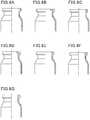
- Fig. 4shows views of an exemplary medical rubber stopper of the present invention, including: (a) a top view, (b) a cross-sectional view, (c) a bottom view, and (d) a side view thereof; and (e) a partially enlarged view of the groove provided at the base of the leg portion (a part of the leg portion which is continuous with the lower surface of the flange region) in the cross-sectional view (circled portion).
- the exemplary medical rubber stopper 1 of the present invention shown in Fig. 4(b)includes a disk-shaped head portion 11 and a leg portion 12.
- the surfaces of the head portion 11 and the leg portion 12are partially laminated with an inert film 13.
- the outer periphery 12a of the leg portion 12is provided with a groove 14.
- the head portion 11includes a flange region 11a, and the leg portion 12 is provided to extend continuously from the inner edge 11c of the (donut-shaped) lower surface 11b of the flange region.
- the leg portion 12is provided to protrude in the shape of a cylinder with a smaller diameter than the outer diameter of the head portion 11 from the lower surface of the head portion 11, specifically from the inner edge 11c of the lower surface of the flange region.
- the thickness of the inert film 13may be appropriately adjusted according to the shape or size of the medical rubber stopper, and is preferably 20 to 200 ⁇ m, more preferably 50 to 100 ⁇ m.
- the medical rubber stopper 1is provided with an annular groove 14 which is not laminated with the inert film 13 so that the base rubber is exposed.
- the groove 14is provided on the outer periphery 12a of the base 12b of the leg portion 12 in a location which is continuous with the inner edge 11c of the lower surface of the flange region.
- the presence of the groove 14 provided at the basefacilitates the contact with the inner wall of a bottle, leading to improved airtightness.
- the groovefits the protrusion, thereby significantly enhancing the airtightness.
- the "annular" shape of the groove 14means a substantially annular shape centered on the central axis of the disk-shaped head portion.
- the cross-sectional shape of the grooveis not particularly limited, and is preferably a simple recess or a rounded recess from the standpoint of productivity.
- Fig. 4(b)shows a case where the number of grooves 14 is one, a plurality of grooves 14 may be provided.
- the width 14w of the groove 14is preferably 0.1 to 10 mm, more preferably 0.5 to 8.0 mm, still more preferably 2.0 to 8.0 mm, from the standpoint of the balance between airtightness and chemical resistance.
- the depth 14d of the groove 14 from the adjacent interface 16 between the base rubber and the inert film 13is preferably 0 to 100 ⁇ m, more preferably 0 to 50 ⁇ m, from the standpoint of airtightness.
- the medical rubber stopper 1is provided with a projection 15 at the edge 14a on the leg portion 12 side of the groove 14.
- the projection 15is configured to be elevated above (protrude from) the adjacent surface 13s of the inert film 13. The presence of the projection 15 further enhances the airtightness.
- the width 15w of the projection 15is preferably 1 to 100 ⁇ m, more preferably 30 to 60 ⁇ m, from the standpoint of airtightness.
- the height 15h of the projection 15 from the adjacent surface 13s of the inert film 13is preferably 1 to 40 ⁇ m, more preferably 10 to 25 ⁇ m, from the standpoint of airtightness. With the projection within the ranges indicated above, the airtightness can be further improved.
- the shape (cross-sectional shape) of the projection 15is not particularly limited, and is preferably a simple projection or a rounded projection from the standpoint of productivity.
- the projection 15may be provided at either one or both edges of the groove 14.
- Fig. 5shows views of another exemplary medical rubber stopper of the present invention, including: (a) a top view, (b) a cross-sectional view, (c) a bottom view, and (d) a side view thereof; and (e) a partially enlarged view of the groove provided on the lower surface of the flange region in the cross-sectional view (circled portion).
- the exemplary medical rubber stopper 2 of the present invention shown in Fig. 5 (b)includes a disk-shaped head portion 21 and a leg portion 22.
- the surfaces of the head portion 21 and the leg portion 22are partially laminated with an inert film 23.
- the lower surface 21b of a flange region 21ais provided with a groove 24.
- the head portion 21 and leg portion 22are provided in the same manner as illustrated in Fig. 4 (flange region 21a, lower surface 21b and inner edge 21c of the flange region) .
- the inert film 23is also similarly laminated, and may have a similar thickness.
- the medical rubber stopper 2is provided with an annular groove 24 which is not laminated with the inert film 23 so that the base rubber is exposed.
- the groove 24is provided in the substantial center of the lower surface 21b of the flange region.
- the presence of the groove 24 provided on the lower surface 21b of the flange regionfacilitates the contact with the mouth surface of a bottle, leading to improved airtightness.
- the groovefits the protrusion, thereby significantly enhancing the airtightness.
- the annular shape, number, and width 24w of the groove 24, and the depth 24d of the groove 24 from the adjacent interface 26 between the base rubber and the inert film 23may be the same as those described above.
- the medical rubber stopper 2is provided with a projection 25 at the edge 24a on the center side of the groove 24.
- the projection 25is configured to be elevated above (protrude from) the adjacent surface 23s of the inert film 23. The presence of the projection 25 further enhances the airtightness.
- the width 25w and shape of the projection 25, and the height 25h of the projection 25 from the adjacent surface 23s of the inert film 23may be the same as those described above.
- the projection 25may be provided at either one or both edges of the groove 24.
- the medical rubber stopper of the present inventionincluding a disk-shaped head portion with a flange region, and a cylindrical leg portion protruding from the lower surface of the head portion and having a smaller diameter than the head portion can be produced by, for example, a method that includes: a molding step including forming by one step molding a rubber stopper in which the lower surface of the flange region and the leg portion are continuously laminated with an inert film; and a groove-forming step including forming an annular groove to expose the base rubber on the lower surface of the flange region and/or the outer periphery of the leg portion each laminated with the inert film.
- a molding stepincluding forming by one step molding a rubber stopper in which the lower surface of the flange region and the leg portion are continuously laminated with an inert film
- a groove-forming stepincluding forming an annular groove to expose the base rubber on the lower surface of the flange region and/or the outer periphery of the leg portion each laminated with the iner
- FIG. 3is a view schematically illustrating the molding step in this production method.
- a forming moldconsists of an upper mold for forming a head portion with a flange region, and a lower mold for forming a leg portion. Each of these molds is connected to a heater (not shown) so that they can be heated.
- the heat source of the heatermay be, for example, an electric heater, vapor, or oil.
- the material of the forming moldis not particularly limited, and known mold materials may be used.
- This one step molding processcan produce a rubber stopper in which the lower surface of the flange region and the leg portion are continuously laminated with an inert film.
- the upper and lower moldsare preheated before the molding of a rubber stopper.
- the preheating temperatureis preferably about 155 to 200°C.
- An inert film superposed on a kneadate sheet (unvulcanized rubber sheet) formed from materials of a rubber stopper bodyis set on the upper surface of the lower mold.
- the upper and lower moldsmay be disposed below and above, respectively, and an unvulcanized rubber sheet on which a lamination film is superposed may be placed on the upper mold.
- the inert filmis not particularly limited, and preferred examples include films of fluorinated resins such as tetrafluoroethylene polymers (PTFE), tetrafluoroethylene-ethylene copolymers (ETFE), modified tetrafluoroethylene polymers, modified tetrafluoroethylene-ethylene copolymers, and chlorofluoroethylene polymers (PCTFE), and films of olefinic resins.
- PTFEtetrafluoroethylene polymers
- ETFEtetrafluoroethylene-ethylene copolymers
- PCTFEchlorofluoroethylene polymers
- the inert filmis more preferably of a fluorinated resin, still more preferably ETFE or modified ETFE.
- the inert filmis preferably subjected to a treatment for enhancing adhesion to rubber or the like (e.g. chemical treatment or surface roughening treatment).
- the kneadate sheet for forming a rubber stopper bodyis formed of an elastic material.
- the elastic material of the rubber stopper bodyis not particularly limited, and examples include rubber materials such as natural rubber, butyl rubber, polyisoprene rubber, polybutadiene rubber, styrene-butadiene rubber, silicone rubber, epichlorohydrin rubber, ethylenepropylene rubber, and nitrile rubber; and thermoplastic elastomers such as polyurethane-based, polyester-based, polyamide-based, olefin-based, and styrene-based thermoplastic elastomers. Preferred among these are materials that become elastic by vulcanization. In the case of vulcanizable materials, compounding agents known in the rubber industry, such as vulcanizing agents (e.g. sulfur) and vulcanization accelerators, may be appropriately added.
- vulcanizing agentse.g. sulfur
- vulcanization acceleratorsmay be appropriately added.
- the kneadate sheetcan be prepared as follows. Compounding materials are mixed at a predetermined ratio using, for example, an internal mixer or open roll mill to give a kneadate, which is then prepared into an unvulcanized rubber sheet using a calendering machine or sheeting machine. Subsequently, an inert film is superposed on the unvulcanized rubber sheet of predetermined weight and size and placed on a mold, followed by vacuum-press molding to obtain a molded sheet including a set of laminated rubber stoppers.
- the molding conditionsare not particularly limited, and may be selected as appropriate.
- the molding temperatureis preferably 155°C to 200°C, more preferably 165°C to 190°C.
- the molding timeis preferably 3 to 15 minutes, more preferably 5 to 10 minutes.
- the rubber stopper prepared in the molding stepis subjected to a groove-forming step that includes forming an annular groove to expose the base rubber on the lower surface of the flange region and/or the outer periphery of the leg portion each laminated with the inert film.
- the groovemay be formed by methods that can expose the base rubber of the laminate of the inert film and the rubber stopper body material, such as grinding.
- grindingcutting tools, laser irradiation (laser processing) or other means may be used.
- laser irradiationlaser processing
- grinding by laser irradiationis suitable because with this method, fine groove structures can be easily formed and also because then there is a smaller influence such as stress around the formation site.
- the laser processingallows for suitable formation of an annular groove having a width and depth as described earlier on the outer periphery of the base of the leg portion or on the lower surface of the flange region.
- the surface of the inert filmis evaporated or decomposed by laser light, and this material is then partially re-accumulated at the edge of the groove to form a projection.
- a projection having a width and height as described earlier and elevated above the adjacent surface of the inert filmcan be suitably formed at at least one edge of the groove.
- the direction of laser irradiationmay be varied to form a projection only at one edge of the groove.
- the type, output, and other conditions of laser lightmay be selected as appropriate.
- laser processing using infrared lightis industrially easy to carry out.
- the irradiation timemay also be selected as appropriate. In order to reduce the influence of heat on the surroundings of the cutting site, short-pulse irradiation is particularly preferred.
- the medical rubber stopper of the present inventionthat may be produced as described above or by other methods is used to seal vials filled with drugs.
- a vial filled with a drugis capped with the medical rubber stopper and then sealed with an aluminum or resin cap before use.
- Flange region diameter19.0 mm (outer diameter), maximum diameter of leg portion: 13.0 mm, flange region thickness: 3.0 mm, thickness of needle penetration site: 2.0 mm
- a desired rubber stopper as illustrated in Fig. 7was prepared in the same manner as in Examples 1 to 3, except that no groove and no projection located at its edge were formed.
- a desired rubber stopperwas prepared in the same manner as in Examples 1 to 3, except that no inert film was used and no groove and no projection located at its edge were formed.
- a desired rubber stopperwas prepared by conventional two step molding.
- a closure stopper vial (b)(inner diameter of mouth: 12.45 mm, full capacity: 14.2 ml, length (in inner diameter direction) and width (in axial direction) of protrusion: 1 to 2 mm) in which the upper surface of the mouth was flat and the inner diameter of the top side of the mouth was reduced to prevent uplifting or dropping of the rubber stopper after capping was used.
- a silica gel desiccant tablet(Yamani chemicals, 0.62 g per tablet) was accurately weighed and placed in a dry and clean 10 ml vial. An aluminum cap was seamed to the vial under normal pressure. The vial was stored in a thermostat at a temperature of 40°C and a humidity of 75% for a month or three months. Then, the silica gel desiccant was taken out and accurately weighed to determine the weight increase (change in the weight of moisture absorbed by the silica gel desiccant) . Table 1 shows the results.
- Table 1shows that the rubber stoppers of the examples as illustrated in Fig. 4 had similarly excellent airtightness as in the reference examples in which the lower surface of the flange region was not laminated with an inert film, while the rubber stopper of the comparative example as illustrated in Fig. 7 had inferior airtightness.
- the rubber stoppers of the examplesexhibited excellent chemical resistance in a test using a liquid drug, and therefore achieved a good balance of excellent airtightness and chemical resistance. Additionally, these rubber stoppers can be produced by one-step molding processes in good productivity.
Landscapes
- Health & Medical Sciences (AREA)
- Mechanical Engineering (AREA)
- Engineering & Computer Science (AREA)
- Veterinary Medicine (AREA)
- General Health & Medical Sciences (AREA)
- Public Health (AREA)
- Animal Behavior & Ethology (AREA)
- Life Sciences & Earth Sciences (AREA)
- Pharmacology & Pharmacy (AREA)
- Medical Preparation Storing Or Oral Administration Devices (AREA)
- Closures For Containers (AREA)
- Moulds For Moulding Plastics Or The Like (AREA)
- Casting Or Compression Moulding Of Plastics Or The Like (AREA)
Description
- The present invention relates to a medical rubber stopper and a method for producing a medical rubber stopper. The features of the preamble of the independent claims are known from
GB 2 106 084 A EP 2 998 237 A1 . - The quality stability of drugs in vials has been improved by laminating the leg portion of a rubber stopper, which is to be in contact with drugs, with an inert film, such as of fluororesin, to improve the chemical resistance of the rubber stopper. Known lamination methods include two-step molding processes (see
Figs. 1 and2 , and Patent Literature 1) and one-step molding processes (seeFig. 3 ). - Rubber stoppers produced by two-step molding processes are excellent in airtightness as the lower surface of their flange region and the base of their leg portion are provided as a rubber surface. The two-step molding processes, however, have a problem in that a molding step and a step of removing unnecessary parts both need to be performed twice, thereby resulting in poor productivity. Another problem is that oily preparations may reach the rubber surface to swell the rubber, thereby resulting in poor chemical resistance and airtightness.
- On the other hand, one-step molding processes can produce rubber stoppers whose flange region has a lower surface entirely laminated with an inert film, and are also excellent in productivity as the number of steps is greatly smaller than that of the two-step molding processes. The airtightness of a vial can be achieved, for example, by bringing the inner wall and the upper surface of the vial into intimate pressure contact with the base of the leg portion and the lower surface of the flange region of a rubber stopper. However, disadvantageously, rubber stoppers produced by the one-step molding processes have poor airtightness because each of the above contact surfaces is hard glass or an inert film.
- Patent Literature 1:
JP 2004-216753 A - The present invention aims to provide a medical rubber stopper that is excellent in chemical resistance and airtightness while having good productivity.
- The present invention, as defined in the independent product claim, relates to a medical rubber stopper, including: a disk-shaped head portion with a flange region; and a cylindrical leg portion protruding from a lower surface of the head portion and having a smaller diameter than the head portion, a lower surface of the flange region and the leg portion being laminated with an inert film, an outer periphery of the leg portion being provided with an annular groove through which the base rubber is exposed.
- Preferably, at least one edge of the groove is provided with a projection elevated above an adjacent surface of the inert film, and the projection has a height of 1 to 40 µm from the adjacent surface of the inert film.
- The groove is preferably provided at least on the outer periphery of the leg portion.
- The groove is preferably provided at least at a base of the leg portion.
- The groove preferably has a width of 0.1 to 10 mm.
- The inert film preferably has a thickness of 200 µm or less.
- The present invention, as defined in the independent process claim, also relates to a method for producing a medical rubber stopper, the medical rubber stopper including: a disk-shaped head portion with a flange region; and a cylindrical leg portion protruding from a lower surface of the head portion and having a smaller diameter than the head portion, the method including: a molding step including forming by one step molding a rubber stopper in which a lower surface of the flange region and the leg portion are continuously laminated with an inert film; and a groove-forming step including forming an annular groove to expose the base rubber on at least one of the lower surface of the flange region or an outer periphery of the leg portion each laminated with the inert film.
- The groove-forming step preferably includes forming the groove by laser processing.
- The present invention relates to a medical rubber stopper in which the lower surface of the flange region and the leg portion are laminated with an inert film, and the lower surface of the flange region and/or the outer periphery of the leg portion is provided with an annular groove through which the base rubber is exposed. The present invention also relates to a method for producing a medical rubber stopper, which includes : a molding step including forming by one step molding a rubber stopper in which the lower surface of the flange region and the leg portion are continuously laminated with an inert film; and a groove-forming step including forming an annular groove to expose the base rubber on the lower surface of the flange region and/or the outer periphery of the leg portion each laminated with the inert film. Accordingly, the present invention can provide a medical rubber stopper that is excellent in chemical resistance and airtightness while having good productivity.
Fig. 1 is a view explaining a leg portion-forming step in a two-step molding process.Fig. 2 is a view explaining a flange region-forming step in a two-step molding process.Fig. 3 is a view explaining a production method based on a one-step molding process.Fig. 4 shows views of an exemplary medical rubber stopper of the present invention or medical rubber stoppers prepared in Examples 1 to 3, including: (a) a top view, (b) an A-A cross-sectional view, (c) a bottom view, and (d) a side view thereof; and (e) a partially enlarged view of the groove provided at the base of the leg portion in the cross-sectional view.Fig. 5 shows views of an exemplary medical rubber stopper of the present invention, including: (a) a top view, (b) a B-B cross-sectional view, (c) a bottom view, and (d) a side view thereof; and (e) a partially enlarged view of the groove provided on the lower surface of the flange region in the cross-sectional view.Fig. 6 shows partial cross-sectional views of the mouths of vials.Fig. 7 shows views of a medical rubber stopper prepared in Comparative Example 1, including: (a) a top view, (b) a C-C cross-sectional view, (c) a bottom view, and (d) a side view.- The present invention relates to a medical rubber stopper including: a disk-shaped head portion with a flange region; and a cylindrical leg portion protruding from the lower surface of the head portion and having a smaller diameter than the head portion. The lower surface of the flange region and the leg portion are laminated with an inert film, and the lower surface of the flange region and/or the outer periphery of the leg portion is provided with an annular groove through which the base rubber is exposed.
- In the medical rubber stopper of the present invention, since the lower surface of the flange region and/or the outer periphery of the leg portion each laminated with an inert film is provided with an annular groove through which the base rubber is exposed, the groove portion where the base rubber is exposed can be brought into sufficiently intimate contact with the upper surface of the mouth and the inner wall of a vial upon capping of the vial, thereby resulting in good airtightness. This is presumably because upon capping of a vial with a rubber stopper designed to have a leg portion diameter larger than the mouth diameter of the vial, and upon sealing of the capped vial with an aluminum cap, the leg portion and the lower surface of the flange region are compressed to allow the base rubber defining the groove to be exposed to facilitate the contact with the upper surface of the mouth and the inner wall of the vial. In addition, the inert film ensures chemical resistance.
- The medical rubber stopper of the present invention is therefore applicable to vials to be filled with drugs in any form, including powder, solid, liquid (solution, oil), and lyophilizate forms, and can provide them with excellent chemical resistance and airtightness.
- Exemplary preferred embodiments of the present invention will be described below with reference to drawings.
Fig. 4 shows views of an exemplary medical rubber stopper of the present invention, including: (a) a top view, (b) a cross-sectional view, (c) a bottom view, and (d) a side view thereof; and (e) a partially enlarged view of the groove provided at the base of the leg portion (a part of the leg portion which is continuous with the lower surface of the flange region) in the cross-sectional view (circled portion).- The exemplary
medical rubber stopper 1 of the present invention shown inFig. 4(b) includes a disk-shaped head portion 11 and aleg portion 12. The surfaces of thehead portion 11 and theleg portion 12 are partially laminated with aninert film 13. Theouter periphery 12a of theleg portion 12 is provided with agroove 14. - The
head portion 11 includes aflange region 11a, and theleg portion 12 is provided to extend continuously from theinner edge 11c of the (donut-shaped)lower surface 11b of the flange region. Theleg portion 12 is provided to protrude in the shape of a cylinder with a smaller diameter than the outer diameter of thehead portion 11 from the lower surface of thehead portion 11, specifically from theinner edge 11c of the lower surface of the flange region. - In the medical rubber stopper 1, since the
lower surface 11b of the flange region and the surface of theleg portion 12 are laminated with aninert film 13, chemical resistance can be ensured for the medical rubber stopper. The thickness of theinert film 13 may be appropriately adjusted according to the shape or size of the medical rubber stopper, and is preferably 20 to 200 µm, more preferably 50 to 100 µm. - The
medical rubber stopper 1 is provided with anannular groove 14 which is not laminated with theinert film 13 so that the base rubber is exposed. Thegroove 14 is provided on theouter periphery 12a of thebase 12b of theleg portion 12 in a location which is continuous with theinner edge 11c of the lower surface of the flange region. The presence of thegroove 14 provided at the base facilitates the contact with the inner wall of a bottle, leading to improved airtightness. Especially in the case of vials having a protrusion on the inner side of their mouth as illustrated inFigs. 6(b) and 6(d) , the groove fits the protrusion, thereby significantly enhancing the airtightness. - The "annular" shape of the
groove 14 means a substantially annular shape centered on the central axis of the disk-shaped head portion. The cross-sectional shape of the groove is not particularly limited, and is preferably a simple recess or a rounded recess from the standpoint of productivity. AlthoughFig. 4(b) shows a case where the number ofgrooves 14 is one, a plurality ofgrooves 14 may be provided. - The
width 14w of thegroove 14 is preferably 0.1 to 10 mm, more preferably 0.5 to 8.0 mm, still more preferably 2.0 to 8.0 mm, from the standpoint of the balance between airtightness and chemical resistance. Thedepth 14d of thegroove 14 from theadjacent interface 16 between the base rubber and theinert film 13 is preferably 0 to 100 µm, more preferably 0 to 50 µm, from the standpoint of airtightness. - As illustrated in the partially enlarged view (e) of the
groove 14, themedical rubber stopper 1 is provided with aprojection 15 at theedge 14a on theleg portion 12 side of thegroove 14. Theprojection 15 is configured to be elevated above (protrude from) theadjacent surface 13s of theinert film 13. The presence of theprojection 15 further enhances the airtightness. - The
width 15w of theprojection 15 is preferably 1 to 100 µm, more preferably 30 to 60 µm, from the standpoint of airtightness. Theheight 15h of theprojection 15 from theadjacent surface 13s of theinert film 13 is preferably 1 to 40 µm, more preferably 10 to 25 µm, from the standpoint of airtightness. With the projection within the ranges indicated above, the airtightness can be further improved. The shape (cross-sectional shape) of theprojection 15 is not particularly limited, and is preferably a simple projection or a rounded projection from the standpoint of productivity. Theprojection 15 may be provided at either one or both edges of thegroove 14. Fig. 5 shows views of another exemplary medical rubber stopper of the present invention, including: (a) a top view, (b) a cross-sectional view, (c) a bottom view, and (d) a side view thereof; and (e) a partially enlarged view of the groove provided on the lower surface of the flange region in the cross-sectional view (circled portion).- The exemplary medical rubber stopper 2 of the present invention shown in
Fig. 5 (b) includes a disk-shapedhead portion 21 and aleg portion 22. The surfaces of thehead portion 21 and theleg portion 22 are partially laminated with aninert film 23. Thelower surface 21b of aflange region 21a is provided with agroove 24. - The
head portion 21 andleg portion 22 are provided in the same manner as illustrated inFig. 4 (flange region 21a,lower surface 21b andinner edge 21c of the flange region) . Theinert film 23 is also similarly laminated, and may have a similar thickness. - The medical rubber stopper 2 is provided with an
annular groove 24 which is not laminated with theinert film 23 so that the base rubber is exposed. Thegroove 24 is provided in the substantial center of thelower surface 21b of the flange region. The presence of thegroove 24 provided on thelower surface 21b of the flange region facilitates the contact with the mouth surface of a bottle, leading to improved airtightness. Especially in the case of vials having a protrusion on the upper surface of their mouth as illustrated inFig. 6(g) , the groove fits the protrusion, thereby significantly enhancing the airtightness. - The annular shape, number, and
width 24w of thegroove 24, and thedepth 24d of thegroove 24 from theadjacent interface 26 between the base rubber and theinert film 23 may be the same as those described above. - As illustrated in the partially enlarged view (e) of the
groove 24, the medical rubber stopper 2 is provided with aprojection 25 at theedge 24a on the center side of thegroove 24. Theprojection 25 is configured to be elevated above (protrude from) theadjacent surface 23s of theinert film 23. The presence of theprojection 25 further enhances the airtightness. - The
width 25w and shape of theprojection 25, and theheight 25h of theprojection 25 from theadjacent surface 23s of theinert film 23 may be the same as those described above. Theprojection 25 may be provided at either one or both edges of thegroove 24. - The medical rubber stopper of the present invention including a disk-shaped head portion with a flange region, and a cylindrical leg portion protruding from the lower surface of the head portion and having a smaller diameter than the head portion can be produced by, for example, a method that includes: a molding step including forming by one step molding a rubber stopper in which the lower surface of the flange region and the leg portion are continuously laminated with an inert film; and a groove-forming step including forming an annular groove to expose the base rubber on the lower surface of the flange region and/or the outer periphery of the leg portion each laminated with the inert film. With this method, medical rubber stoppers having excellent chemical resistance and airtightness can be produced in good productivity.
Fig. 3 is a view schematically illustrating the molding step in this production method. A forming mold consists of an upper mold for forming a head portion with a flange region, and a lower mold for forming a leg portion. Each of these molds is connected to a heater (not shown) so that they can be heated. The heat source of the heater may be, for example, an electric heater, vapor, or oil. The material of the forming mold is not particularly limited, and known mold materials may be used. This one step molding process can produce a rubber stopper in which the lower surface of the flange region and the leg portion are continuously laminated with an inert film.- In the molding step, the upper and lower molds are preheated before the molding of a rubber stopper. The preheating temperature is preferably about 155 to 200°C.
- An inert film superposed on a kneadate sheet (unvulcanized rubber sheet) formed from materials of a rubber stopper body is set on the upper surface of the lower mold. Here, the upper and lower molds may be disposed below and above, respectively, and an unvulcanized rubber sheet on which a lamination film is superposed may be placed on the upper mold.
- The inert film is not particularly limited, and preferred examples include films of fluorinated resins such as tetrafluoroethylene polymers (PTFE), tetrafluoroethylene-ethylene copolymers (ETFE), modified tetrafluoroethylene polymers, modified tetrafluoroethylene-ethylene copolymers, and chlorofluoroethylene polymers (PCTFE), and films of olefinic resins. For good chemical resistance, the inert film is more preferably of a fluorinated resin, still more preferably ETFE or modified ETFE. The inert film is preferably subjected to a treatment for enhancing adhesion to rubber or the like (e.g. chemical treatment or surface roughening treatment).
- The kneadate sheet for forming a rubber stopper body is formed of an elastic material. The elastic material of the rubber stopper body is not particularly limited, and examples include rubber materials such as natural rubber, butyl rubber, polyisoprene rubber, polybutadiene rubber, styrene-butadiene rubber, silicone rubber, epichlorohydrin rubber, ethylenepropylene rubber, and nitrile rubber; and thermoplastic elastomers such as polyurethane-based, polyester-based, polyamide-based, olefin-based, and styrene-based thermoplastic elastomers. Preferred among these are materials that become elastic by vulcanization. In the case of vulcanizable materials, compounding agents known in the rubber industry, such as vulcanizing agents (e.g. sulfur) and vulcanization accelerators, may be appropriately added.
- The kneadate sheet can be prepared as follows. Compounding materials are mixed at a predetermined ratio using, for example, an internal mixer or open roll mill to give a kneadate, which is then prepared into an unvulcanized rubber sheet using a calendering machine or sheeting machine. Subsequently, an inert film is superposed on the unvulcanized rubber sheet of predetermined weight and size and placed on a mold, followed by vacuum-press molding to obtain a molded sheet including a set of laminated rubber stoppers.
- The molding conditions are not particularly limited, and may be selected as appropriate. The molding temperature is preferably 155°C to 200°C, more preferably 165°C to 190°C. The molding time is preferably 3 to 15 minutes, more preferably 5 to 10 minutes.
- If needed, unnecessary parts may be cut and removed from the molded rubber stopper, and the upper surface of the flange region or the surface laminated with the inert film of the rubber stopper may be coated with a non-reactive or reactive silicone.
- Next, the rubber stopper prepared in the molding step is subjected to a groove-forming step that includes forming an annular groove to expose the base rubber on the lower surface of the flange region and/or the outer periphery of the leg portion each laminated with the inert film.
- The groove may be formed by methods that can expose the base rubber of the laminate of the inert film and the rubber stopper body material, such as grinding. For the grinding, cutting tools, laser irradiation (laser processing) or other means may be used. Among these, grinding by laser irradiation is suitable because with this method, fine groove structures can be easily formed and also because then there is a smaller influence such as stress around the formation site.
- The laser processing allows for suitable formation of an annular groove having a width and depth as described earlier on the outer periphery of the base of the leg portion or on the lower surface of the flange region. In addition, the surface of the inert film is evaporated or decomposed by laser light, and this material is then partially re-accumulated at the edge of the groove to form a projection. Thus, a projection having a width and height as described earlier and elevated above the adjacent surface of the inert film can be suitably formed at at least one edge of the groove. The direction of laser irradiation may be varied to form a projection only at one edge of the groove.
- The type, output, and other conditions of laser light may be selected as appropriate. For example, laser processing using infrared light is industrially easy to carry out. The irradiation time may also be selected as appropriate. In order to reduce the influence of heat on the surroundings of the cutting site, short-pulse irradiation is particularly preferred.
- The medical rubber stopper of the present invention that may be produced as described above or by other methods is used to seal vials filled with drugs. For example, a vial filled with a drug is capped with the medical rubber stopper and then sealed with an aluminum or resin cap before use.
- The present invention is specifically described with reference to, but not limited to, examples.
- An inert film with one adhesive-treated surface superposed on an unvulcanized rubber sheet, which are described below, was placed on a forming mold and vulcanization-bonded using a vacuum press at 175°C for 10 minutes for one step molding to prepare a rubber stopper having the shape described below. Both surfaces were silicone-coated, and burrs were removed. Then, an annular groove having the width and depth listed in Table 1 and a projection having the width and height listed in Table 1 (at the edge of the groove) were formed at the base of the leg portion using a laser device as described below. Then, cleaning, sterilization, and drying were performed to obtain a desired rubber stopper as illustrated in
Fig. 4 . - Unvulcanized rubber sheet: 100 parts by mass of chlorinated butyl rubber added to 50 parts by mass of a silica-based filler (JIS-A hardness: 45).
- Inert film: modified ETFE "AFLEX" (thickness: 75 µm, surface roughness Ra (µm) : 0.02 to 0.03 (cut-off value: 0.08, evaluation length: 0.25)) available from Asahi Glass Co., LTD.
- Laser device: ML-Z9550T available from Keyence Corporation
- Flange region diameter: 19.0 mm (outer diameter), maximum diameter of leg portion: 13.0 mm, flange region thickness: 3.0 mm, thickness of needle penetration site: 2.0 mm
- A desired rubber stopper as illustrated in
Fig. 7 was prepared in the same manner as in Examples 1 to 3, except that no groove and no projection located at its edge were formed. - A desired rubber stopper was prepared in the same manner as in Examples 1 to 3, except that no inert film was used and no groove and no projection located at its edge were formed.
- A desired rubber stopper was prepared by conventional two step molding.
- Among glass vials in various shapes such as those illustrated in
Figs. 6(a) to 6(g) , a closure stopper vial (b) (inner diameter of mouth: 12.45 mm, full capacity: 14.2 ml, length (in inner diameter direction) and width (in axial direction) of protrusion: 1 to 2 mm) in which the upper surface of the mouth was flat and the inner diameter of the top side of the mouth was reduced to prevent uplifting or dropping of the rubber stopper after capping was used. - A silica gel desiccant tablet (Yamani chemicals, 0.62 g per tablet) was accurately weighed and placed in a dry and clean 10 ml vial. An aluminum cap was seamed to the vial under normal pressure. The vial was stored in a thermostat at a temperature of 40°C and a humidity of 75% for a month or three months. Then, the silica gel desiccant was taken out and accurately weighed to determine the weight increase (change in the weight of moisture absorbed by the silica gel desiccant) . Table 1 shows the results.
[Table 1] Rubber stopper Airtightness test Inert film Groove formation by laser Width of groove (mm) Depth of groove (µm) Height of projection (µm) Width of projection (µm) One month later (mg) Three months later (mg) Example 1 Modified ETFE Formed 1 42 19 49 0.8 1.5 Example 2 Modified ETFE Formed 3 51 22 53 0.7 1.6 Example 3 Modified ETFE Formed 7 47 24 43 0.5 1.2 Comparative Example 1 Modified ETFE Not formed - - - - 28.5 65.8 Reference Example 1 Not used Not formed - - - - 0.5 1.1 Reference Example 2 Modified ETFE Not formed - - - - 0.7 1.4 - Table 1 shows that the rubber stoppers of the examples as illustrated in
Fig. 4 had similarly excellent airtightness as in the reference examples in which the lower surface of the flange region was not laminated with an inert film, while the rubber stopper of the comparative example as illustrated inFig. 7 had inferior airtightness. - Moreover, the rubber stoppers of the examples exhibited excellent chemical resistance in a test using a liquid drug, and therefore achieved a good balance of excellent airtightness and chemical resistance. Additionally, these rubber stoppers can be produced by one-step molding processes in good productivity.
- 1:
- medical rubber stopper
- 11:
- head portion
- 11a:
- flange region
- 11b:
- lower surface of flange region
- 11c:
- inner edge of lower surface of flange region
- 12:
- leg portion
- 12a:
- outer periphery of leg portion
- 12b:
- base of leg portion
- 13:
- inert film
- 13s:
- surface of inert film
- 14:
- groove
- 14a:
- edge of groove
- 14w:
- width of groove
- 14d:
- depth of groove
- 15:
- projection
- 15w:
- width of projection
- 15h:
- height of projection
- 16:
- interface between base rubber and inert film
- 2:
- medical rubber stopper
- 21:
- head portion
- 21a:
- flange region
- 21b:
- lower surface of flange region
- 21c:
- inner edge of lower surface of flange region
- 22:
- leg portion
- 23:
- inert film
- 23s:
- surface of inert film
- 24:
- groove
- 24a:
- edge of groove
- 24w:
- width of groove
- 24d:
- depth of groove
- 25:
- projection
- 25w:
- width of projection
- 25h:
- height of projection
- 26:
- interface between base rubber and inert film
Claims (8)
- A medical rubber stopper (1), comprising:a disk-shaped head portion (11) with a flange region (11a); anda cylindrical leg portion (12) protruding from a lower surface (11b) of the head portion (11) and having a smaller diameter than the head portion (11),a lower surface (11b) of the flange region (11a) and the leg portion (12) being laminated with an inert film (13),characterized byan outer periphery (12a) of the leg portion (12) being provided with an annular groove (14) through which the base rubber (1) is exposed.
- The medical rubber stopper according to claim 1,
wherein at least one edge of the groove (14) is provided with a projection (15) elevated above an adjacent surface of the inert film (13), and the projection (15) has a height (15h) of 1 to 40 µm from the adjacent surface of the inert film (13) . - The medical rubber stopper according to claim 1 or 2,
wherein the groove (14) is provided at least on the outer periphery (12a) of the leg portion (12). - The medical rubber stopper according to any one of claims 1 to 3,
wherein the groove (14) is provided at least at a base of the leg portion (12). - The medical rubber stopper according to any one of claims 1 to 4,
wherein the groove (14) has a width of 0.1 to 10 mm. - The medical rubber stopper according to any one of claims 1 to 5,
wherein the inert film (13) has a thickness of 200 µm or less. - A method for producing a medical rubber stopper (1,2), the medical rubber stopper (1,2) comprising: a disk-shaped head portion (11,21) with a flange region (11a,21a); and a cylindrical leg portion (12,22) protruding from a lower surface (11b, 21b) of the head portion (11,21) and having a smaller diameter than the head portion (11,21), the method comprising:a molding step including forming by one step molding a rubber stopper (1,2) in which a lower surface (11b,21b) of the flange region (11a,21a) and the leg portion (12,22) are continuously laminated with an inert film (13,23);characterized bya groove-forming step including forming an annular groove (14,24) to expose the base rubber on at least one of the lower surface (11b,21b) of the flange region (11a,21a) or an outer periphery of the leg portion (12,22) each laminated with the inert film (13,23).
- The method for producing a medical rubber stopper (1,2) according to claim 7,
wherein the groove-forming step includes forming the groove (14,24) by laser processing.
Applications Claiming Priority (1)
| Application Number | Priority Date | Filing Date | Title |
|---|---|---|---|
| JP2016095486AJP2017202848A (en) | 2016-05-11 | 2016-05-11 | Medical rubber plug and manufacturing method of the same |
Publications (2)
| Publication Number | Publication Date |
|---|---|
| EP3243625A1 EP3243625A1 (en) | 2017-11-15 |
| EP3243625B1true EP3243625B1 (en) | 2019-08-07 |
Family
ID=58701399
Family Applications (1)
| Application Number | Title | Priority Date | Filing Date |
|---|---|---|---|
| EP17168140.6AActiveEP3243625B1 (en) | 2016-05-11 | 2017-04-26 | Medical rubber stopper and method for producing medical rubber stopper |
Country Status (4)
| Country | Link |
|---|---|
| US (1) | US10285905B2 (en) |
| EP (1) | EP3243625B1 (en) |
| JP (1) | JP2017202848A (en) |
| CN (1) | CN107364161B (en) |
Families Citing this family (9)
| Publication number | Priority date | Publication date | Assignee | Title |
|---|---|---|---|---|
| IT201700047199A1 (en)* | 2017-05-02 | 2018-11-02 | Goglio Spa | Pressure cap and airtight container equipped with this pressure cap |
| UA119731C2 (en)* | 2018-08-29 | 2019-07-25 | Сіа Емтеко Холдинг | LIQUID DOSAGE FORM OF EDARAVON OR ITS PHARMACEUTICALLY ACCEPTABLE SALTS, STABLE DURING STORAGE, TRANSPORTATION AND USE |
| JP7209175B2 (en)* | 2018-10-04 | 2023-01-20 | 住友ゴム工業株式会社 | METHOD FOR MANUFACTURING MEDICAL RUBBER PRODUCTS |
| BR112021021873A2 (en)* | 2019-05-03 | 2022-01-25 | Janssen Biotech Inc | Low temperature vials and vial sets |
| CN111231455A (en)* | 2020-01-14 | 2020-06-05 | 烟台鑫汇包装有限公司 | A kind of solvent-resistant inert resin-coated fluororubber sealing plug and manufacturing method |
| KR102218574B1 (en)* | 2020-08-17 | 2021-02-22 | 삼성의료고무주식회사 | Marking method for rubber cover |
| CN112409710B (en)* | 2020-11-03 | 2023-05-12 | 山东省药用玻璃股份有限公司 | Freeze-dried tectorial membrane butyl rubber plug and preparation method thereof |
| AU2021405307A1 (en)* | 2020-12-23 | 2023-06-22 | Daikyo Seiko, Ltd. | Rubber stopper |
| WO2022175282A1 (en)* | 2021-02-19 | 2022-08-25 | Braunform Gmbh | Cap for closing a container for administering a medication, and method for producing same |
Citations (1)
| Publication number | Priority date | Publication date | Assignee | Title |
|---|---|---|---|---|
| EP0172613A2 (en)* | 1984-07-31 | 1986-02-26 | Kabushiki Kaisha Daikyo Gomu Seiko | Resin-laminated rubber plug |
Family Cites Families (22)
| Publication number | Priority date | Publication date | Assignee | Title |
|---|---|---|---|---|
| US3527215A (en)* | 1967-02-20 | 1970-09-08 | American Hospital Supply Corp | Syringe construction having internal bladder |
| FR1538462A (en)* | 1967-07-24 | 1968-09-06 | Improvements made to caps, especially for therapeutic bottles | |
| US3584770A (en)* | 1969-01-28 | 1971-06-15 | Philip Taylor | Intravenous bottle having expandable inner receptacle |
| JPS5520200A (en)* | 1978-08-01 | 1980-02-13 | Coulter Electronics | Bottle sealing method* bottle seal closing cap and method of making same |
| JPS5749739Y2 (en)* | 1978-08-25 | 1982-10-30 | ||
| US4386929A (en)* | 1980-01-18 | 1983-06-07 | Alza Corporation | Elastomeric bladder assembly |
| JPS5829939U (en)* | 1981-08-24 | 1983-02-26 | 武田薬品工業株式会社 | Rubber stopper for vial |
| JPH03140231A (en)* | 1989-10-26 | 1991-06-14 | Nissho Corp | Rubber plug for vial |
| US5343901A (en)* | 1993-03-17 | 1994-09-06 | Philip Meshberg | Insertable barrier bag or liner for a narrow neck dispensing container and method of filling such a barrier bag or liner |
| JPH08175554A (en)* | 1994-12-22 | 1996-07-09 | Kazusa Koshitsu Chrome:Kk | Rubber stopper, and manufacture thereof |
| JP2004216753A (en)* | 2003-01-16 | 2004-08-05 | Sumitomo Rubber Ind Ltd | Method for producing rubber stopper for pharmaceuticals |
| JP4372736B2 (en)* | 2004-09-14 | 2009-11-25 | 株式会社大協精工 | Pharmaceutical container set, pharmaceutical container and rubber stopper |
| US7547300B2 (en)* | 2006-04-12 | 2009-06-16 | Icu Medical, Inc. | Vial adaptor for regulating pressure |
| US7618408B2 (en)* | 2006-09-20 | 2009-11-17 | Yandell Marion E | Vial assembly and method for reducing nosocomial infections |
| US7887528B2 (en)* | 2006-09-20 | 2011-02-15 | Yandell Marion E | Vial assembly and method for reducing nosocomial infections |
| WO2010022095A1 (en)* | 2008-08-20 | 2010-02-25 | Icu Medical, Inc. | Anti-reflux vial adaptors |
| US8544665B2 (en)* | 2011-04-04 | 2013-10-01 | Genesis Packaging Technologies | Cap systems and methods for sealing pharmaceutical vials |
| US8357137B2 (en)* | 2011-06-24 | 2013-01-22 | Yandell Marion E | Bung assembly for anti vacuum lock medical vials |
| JP6215546B2 (en)* | 2013-03-21 | 2017-10-18 | 住友ゴム工業株式会社 | Gasket for prefilled syringe |
| CN103252860A (en)* | 2013-05-27 | 2013-08-21 | 盛州橡塑胶(苏州)有限公司 | Secondary forming method for freeze-dried powder laminated rubber plug |
| JP6270265B2 (en)* | 2014-02-05 | 2018-01-31 | 住友ゴム工業株式会社 | Medical syringe, gasket applied to the syringe, and manufacturing method thereof |
| JP6403258B2 (en)* | 2014-09-16 | 2018-10-10 | 住友ゴム工業株式会社 | Manufacturing method of medical rubber stopper |
- 2016
- 2016-05-11JPJP2016095486Apatent/JP2017202848A/enactivePending
- 2017
- 2017-03-27CNCN201710186855.1Apatent/CN107364161B/enactiveActive
- 2017-04-13USUS15/487,103patent/US10285905B2/enactiveActive
- 2017-04-26EPEP17168140.6Apatent/EP3243625B1/enactiveActive
Patent Citations (1)
| Publication number | Priority date | Publication date | Assignee | Title |
|---|---|---|---|---|
| EP0172613A2 (en)* | 1984-07-31 | 1986-02-26 | Kabushiki Kaisha Daikyo Gomu Seiko | Resin-laminated rubber plug |
Also Published As
| Publication number | Publication date |
|---|---|
| JP2017202848A (en) | 2017-11-16 |
| US20170326031A1 (en) | 2017-11-16 |
| CN107364161B (en) | 2021-05-28 |
| US10285905B2 (en) | 2019-05-14 |
| EP3243625A1 (en) | 2017-11-15 |
| CN107364161A (en) | 2017-11-21 |
Similar Documents
| Publication | Publication Date | Title |
|---|---|---|
| EP3243625B1 (en) | Medical rubber stopper and method for producing medical rubber stopper | |
| EP2998237B1 (en) | Method for manufacturing a medical rubber closure | |
| EP3053619B1 (en) | Medical syringe, gasket used for syringe and method for producing same | |
| JP3172057B2 (en) | Laminated rubber stopper | |
| EP3120886B1 (en) | Medical syringe, gasket for use in the syringe, and gasket production method | |
| JP3222491U (en) | Film-coated rubber stopper | |
| EP2902060B1 (en) | Medical gasket manufacturing method | |
| EP3409311B1 (en) | Method for producing syringe gasket, and syringe including the gasket | |
| EP3058975B1 (en) | Prefilled syringe, gasket for use in prefilled syringe, and gasket production method | |
| EP3225270B1 (en) | Medical syringe, gasket to be used for syringe, and gasket production method | |
| US5217668A (en) | Method for producing a rubber stopper for a vial | |
| JPH0223961A (en) | Laminated rubber plug for medicine, method and mold for preparing the same | |
| JP6986202B2 (en) | Manufacturing method of laminated rubber stopper for vial | |
| JPH0422362A (en) | Rubber plug for medicine vessel | |
| JPH0111235Y2 (en) | ||
| JPS61272134A (en) | Manufacture of rubber stopper for vial | |
| JPH03270928A (en) | Manufacture of rubber stopper for vial | |
| JP2004216753A (en) | Method for producing rubber stopper for pharmaceuticals | |
| JP2869107B2 (en) | Rubber stopper for vial | |
| CN113211704A (en) | Film-coated rubber plug forming die and forming method | |
| JPH04173322A (en) | Manufacture of rubber plug for vial | |
| JPH05201456A (en) | Rubber plug for medicine container | |
| JP2956046B2 (en) | Method for manufacturing rubber stopper for vial |
Legal Events
| Date | Code | Title | Description |
|---|---|---|---|
| PUAI | Public reference made under article 153(3) epc to a published international application that has entered the european phase | Free format text:ORIGINAL CODE: 0009012 | |
| STAA | Information on the status of an ep patent application or granted ep patent | Free format text:STATUS: THE APPLICATION HAS BEEN PUBLISHED | |
| AK | Designated contracting states | Kind code of ref document:A1 Designated state(s):AL AT BE BG CH CY CZ DE DK EE ES FI FR GB GR HR HU IE IS IT LI LT LU LV MC MK MT NL NO PL PT RO RS SE SI SK SM TR | |
| AX | Request for extension of the european patent | Extension state:BA ME | |
| STAA | Information on the status of an ep patent application or granted ep patent | Free format text:STATUS: REQUEST FOR EXAMINATION WAS MADE | |
| 17P | Request for examination filed | Effective date:20180409 | |
| RBV | Designated contracting states (corrected) | Designated state(s):AL AT BE BG CH CY CZ DE DK EE ES FI FR GB GR HR HU IE IS IT LI LT LU LV MC MK MT NL NO PL PT RO RS SE SI SK SM TR | |
| REG | Reference to a national code | Ref country code:DE Ref legal event code:R079 Ref document number:602017005803 Country of ref document:DE Free format text:PREVIOUS MAIN CLASS: B29C0043200000 Ipc:A61J0001060000 | |
| GRAP | Despatch of communication of intention to grant a patent | Free format text:ORIGINAL CODE: EPIDOSNIGR1 | |
| STAA | Information on the status of an ep patent application or granted ep patent | Free format text:STATUS: GRANT OF PATENT IS INTENDED | |
| RIC1 | Information provided on ipc code assigned before grant | Ipc:B23K 26/402 20140101ALN20190314BHEP Ipc:A61J 1/06 20060101AFI20190314BHEP Ipc:B29L 31/00 20060101ALN20190314BHEP Ipc:A61J 1/14 20060101ALI20190314BHEP Ipc:B65D 51/00 20060101ALI20190314BHEP Ipc:B23K 26/00 20140101ALN20190314BHEP Ipc:B29C 43/18 20060101ALI20190314BHEP Ipc:B29L 31/56 20060101ALN20190314BHEP Ipc:B65D 39/00 20060101ALN20190314BHEP | |
| INTG | Intention to grant announced | Effective date:20190415 | |
| RIN1 | Information on inventor provided before grant (corrected) | Inventor name:NAKANO, HIROAKI Inventor name:MASUYAMA, YOSHIKAZU | |
| GRAS | Grant fee paid | Free format text:ORIGINAL CODE: EPIDOSNIGR3 | |
| GRAA | (expected) grant | Free format text:ORIGINAL CODE: 0009210 | |
| STAA | Information on the status of an ep patent application or granted ep patent | Free format text:STATUS: THE PATENT HAS BEEN GRANTED | |
| AK | Designated contracting states | Kind code of ref document:B1 Designated state(s):AL AT BE BG CH CY CZ DE DK EE ES FI FR GB GR HR HU IE IS IT LI LT LU LV MC MK MT NL NO PL PT RO RS SE SI SK SM TR | |
| REG | Reference to a national code | Ref country code:GB Ref legal event code:FG4D | |
| REG | Reference to a national code | Ref country code:CH Ref legal event code:EP Ref country code:AT Ref legal event code:REF Ref document number:1162710 Country of ref document:AT Kind code of ref document:T Effective date:20190815 | |
| REG | Reference to a national code | Ref country code:DE Ref legal event code:R096 Ref document number:602017005803 Country of ref document:DE | |
| REG | Reference to a national code | Ref country code:IE Ref legal event code:FG4D | |
| REG | Reference to a national code | Ref country code:NL Ref legal event code:MP Effective date:20190807 | |
| REG | Reference to a national code | Ref country code:LT Ref legal event code:MG4D | |
| PG25 | Lapsed in a contracting state [announced via postgrant information from national office to epo] | Ref country code:PT Free format text:LAPSE BECAUSE OF FAILURE TO SUBMIT A TRANSLATION OF THE DESCRIPTION OR TO PAY THE FEE WITHIN THE PRESCRIBED TIME-LIMIT Effective date:20191209 Ref country code:NL Free format text:LAPSE BECAUSE OF FAILURE TO SUBMIT A TRANSLATION OF THE DESCRIPTION OR TO PAY THE FEE WITHIN THE PRESCRIBED TIME-LIMIT Effective date:20190807 Ref country code:HR Free format text:LAPSE BECAUSE OF FAILURE TO SUBMIT A TRANSLATION OF THE DESCRIPTION OR TO PAY THE FEE WITHIN THE PRESCRIBED TIME-LIMIT Effective date:20190807 Ref country code:LT Free format text:LAPSE BECAUSE OF FAILURE TO SUBMIT A TRANSLATION OF THE DESCRIPTION OR TO PAY THE FEE WITHIN THE PRESCRIBED TIME-LIMIT Effective date:20190807 Ref country code:BG Free format text:LAPSE BECAUSE OF FAILURE TO SUBMIT A TRANSLATION OF THE DESCRIPTION OR TO PAY THE FEE WITHIN THE PRESCRIBED TIME-LIMIT Effective date:20191107 Ref country code:SE Free format text:LAPSE BECAUSE OF FAILURE TO SUBMIT A TRANSLATION OF THE DESCRIPTION OR TO PAY THE FEE WITHIN THE PRESCRIBED TIME-LIMIT Effective date:20190807 Ref country code:FI Free format text:LAPSE BECAUSE OF FAILURE TO SUBMIT A TRANSLATION OF THE DESCRIPTION OR TO PAY THE FEE WITHIN THE PRESCRIBED TIME-LIMIT Effective date:20190807 Ref country code:NO Free format text:LAPSE BECAUSE OF FAILURE TO SUBMIT A TRANSLATION OF THE DESCRIPTION OR TO PAY THE FEE WITHIN THE PRESCRIBED TIME-LIMIT Effective date:20191107 | |
| REG | Reference to a national code | Ref country code:AT Ref legal event code:MK05 Ref document number:1162710 Country of ref document:AT Kind code of ref document:T Effective date:20190807 | |
| PG25 | Lapsed in a contracting state [announced via postgrant information from national office to epo] | Ref country code:ES Free format text:LAPSE BECAUSE OF FAILURE TO SUBMIT A TRANSLATION OF THE DESCRIPTION OR TO PAY THE FEE WITHIN THE PRESCRIBED TIME-LIMIT Effective date:20190807 Ref country code:RS Free format text:LAPSE BECAUSE OF FAILURE TO SUBMIT A TRANSLATION OF THE DESCRIPTION OR TO PAY THE FEE WITHIN THE PRESCRIBED TIME-LIMIT Effective date:20190807 Ref country code:LV Free format text:LAPSE BECAUSE OF FAILURE TO SUBMIT A TRANSLATION OF THE DESCRIPTION OR TO PAY THE FEE WITHIN THE PRESCRIBED TIME-LIMIT Effective date:20190807 Ref country code:IS Free format text:LAPSE BECAUSE OF FAILURE TO SUBMIT A TRANSLATION OF THE DESCRIPTION OR TO PAY THE FEE WITHIN THE PRESCRIBED TIME-LIMIT Effective date:20191207 Ref country code:AL Free format text:LAPSE BECAUSE OF FAILURE TO SUBMIT A TRANSLATION OF THE DESCRIPTION OR TO PAY THE FEE WITHIN THE PRESCRIBED TIME-LIMIT Effective date:20190807 Ref country code:GR Free format text:LAPSE BECAUSE OF FAILURE TO SUBMIT A TRANSLATION OF THE DESCRIPTION OR TO PAY THE FEE WITHIN THE PRESCRIBED TIME-LIMIT Effective date:20191108 | |
| PG25 | Lapsed in a contracting state [announced via postgrant information from national office to epo] | Ref country code:TR Free format text:LAPSE BECAUSE OF FAILURE TO SUBMIT A TRANSLATION OF THE DESCRIPTION OR TO PAY THE FEE WITHIN THE PRESCRIBED TIME-LIMIT Effective date:20190807 | |
| PG25 | Lapsed in a contracting state [announced via postgrant information from national office to epo] | Ref country code:IT Free format text:LAPSE BECAUSE OF FAILURE TO SUBMIT A TRANSLATION OF THE DESCRIPTION OR TO PAY THE FEE WITHIN THE PRESCRIBED TIME-LIMIT Effective date:20190807 Ref country code:RO Free format text:LAPSE BECAUSE OF FAILURE TO SUBMIT A TRANSLATION OF THE DESCRIPTION OR TO PAY THE FEE WITHIN THE PRESCRIBED TIME-LIMIT Effective date:20190807 Ref country code:EE Free format text:LAPSE BECAUSE OF FAILURE TO SUBMIT A TRANSLATION OF THE DESCRIPTION OR TO PAY THE FEE WITHIN THE PRESCRIBED TIME-LIMIT Effective date:20190807 Ref country code:AT Free format text:LAPSE BECAUSE OF FAILURE TO SUBMIT A TRANSLATION OF THE DESCRIPTION OR TO PAY THE FEE WITHIN THE PRESCRIBED TIME-LIMIT Effective date:20190807 Ref country code:DK Free format text:LAPSE BECAUSE OF FAILURE TO SUBMIT A TRANSLATION OF THE DESCRIPTION OR TO PAY THE FEE WITHIN THE PRESCRIBED TIME-LIMIT Effective date:20190807 Ref country code:PL Free format text:LAPSE BECAUSE OF FAILURE TO SUBMIT A TRANSLATION OF THE DESCRIPTION OR TO PAY THE FEE WITHIN THE PRESCRIBED TIME-LIMIT Effective date:20190807 | |
| PG25 | Lapsed in a contracting state [announced via postgrant information from national office to epo] | Ref country code:SK Free format text:LAPSE BECAUSE OF FAILURE TO SUBMIT A TRANSLATION OF THE DESCRIPTION OR TO PAY THE FEE WITHIN THE PRESCRIBED TIME-LIMIT Effective date:20190807 Ref country code:IS Free format text:LAPSE BECAUSE OF FAILURE TO SUBMIT A TRANSLATION OF THE DESCRIPTION OR TO PAY THE FEE WITHIN THE PRESCRIBED TIME-LIMIT Effective date:20200224 Ref country code:SM Free format text:LAPSE BECAUSE OF FAILURE TO SUBMIT A TRANSLATION OF THE DESCRIPTION OR TO PAY THE FEE WITHIN THE PRESCRIBED TIME-LIMIT Effective date:20190807 Ref country code:CZ Free format text:LAPSE BECAUSE OF FAILURE TO SUBMIT A TRANSLATION OF THE DESCRIPTION OR TO PAY THE FEE WITHIN THE PRESCRIBED TIME-LIMIT Effective date:20190807 | |
| REG | Reference to a national code | Ref country code:DE Ref legal event code:R097 Ref document number:602017005803 Country of ref document:DE | |
| PLBE | No opposition filed within time limit | Free format text:ORIGINAL CODE: 0009261 | |
| STAA | Information on the status of an ep patent application or granted ep patent | Free format text:STATUS: NO OPPOSITION FILED WITHIN TIME LIMIT | |
| PG2D | Information on lapse in contracting state deleted | Ref country code:IS | |
| 26N | No opposition filed | Effective date:20200603 | |
| PG25 | Lapsed in a contracting state [announced via postgrant information from national office to epo] | Ref country code:SI Free format text:LAPSE BECAUSE OF FAILURE TO SUBMIT A TRANSLATION OF THE DESCRIPTION OR TO PAY THE FEE WITHIN THE PRESCRIBED TIME-LIMIT Effective date:20190807 | |
| PG25 | Lapsed in a contracting state [announced via postgrant information from national office to epo] | Ref country code:MC Free format text:LAPSE BECAUSE OF FAILURE TO SUBMIT A TRANSLATION OF THE DESCRIPTION OR TO PAY THE FEE WITHIN THE PRESCRIBED TIME-LIMIT Effective date:20190807 | |
| REG | Reference to a national code | Ref country code:CH Ref legal event code:PL | |
| PG25 | Lapsed in a contracting state [announced via postgrant information from national office to epo] | Ref country code:LU Free format text:LAPSE BECAUSE OF NON-PAYMENT OF DUE FEES Effective date:20200426 Ref country code:CH Free format text:LAPSE BECAUSE OF NON-PAYMENT OF DUE FEES Effective date:20200430 Ref country code:LI Free format text:LAPSE BECAUSE OF NON-PAYMENT OF DUE FEES Effective date:20200430 | |
| REG | Reference to a national code | Ref country code:BE Ref legal event code:MM Effective date:20200430 | |
| PG25 | Lapsed in a contracting state [announced via postgrant information from national office to epo] | Ref country code:BE Free format text:LAPSE BECAUSE OF NON-PAYMENT OF DUE FEES Effective date:20200430 | |
| PG25 | Lapsed in a contracting state [announced via postgrant information from national office to epo] | Ref country code:IE Free format text:LAPSE BECAUSE OF NON-PAYMENT OF DUE FEES Effective date:20200426 | |
| GBPC | Gb: european patent ceased through non-payment of renewal fee | Effective date:20210426 | |
| PG25 | Lapsed in a contracting state [announced via postgrant information from national office to epo] | Ref country code:GB Free format text:LAPSE BECAUSE OF NON-PAYMENT OF DUE FEES Effective date:20210426 | |
| PG25 | Lapsed in a contracting state [announced via postgrant information from national office to epo] | Ref country code:MT Free format text:LAPSE BECAUSE OF FAILURE TO SUBMIT A TRANSLATION OF THE DESCRIPTION OR TO PAY THE FEE WITHIN THE PRESCRIBED TIME-LIMIT Effective date:20190807 Ref country code:CY Free format text:LAPSE BECAUSE OF FAILURE TO SUBMIT A TRANSLATION OF THE DESCRIPTION OR TO PAY THE FEE WITHIN THE PRESCRIBED TIME-LIMIT Effective date:20190807 | |
| PG25 | Lapsed in a contracting state [announced via postgrant information from national office to epo] | Ref country code:MK Free format text:LAPSE BECAUSE OF FAILURE TO SUBMIT A TRANSLATION OF THE DESCRIPTION OR TO PAY THE FEE WITHIN THE PRESCRIBED TIME-LIMIT Effective date:20190807 | |
| P01 | Opt-out of the competence of the unified patent court (upc) registered | Effective date:20230510 | |
| PGFP | Annual fee paid to national office [announced via postgrant information from national office to epo] | Ref country code:FR Payment date:20250310 Year of fee payment:9 | |
| PGFP | Annual fee paid to national office [announced via postgrant information from national office to epo] | Ref country code:DE Payment date:20250305 Year of fee payment:9 |