EP3243476B1 - Systems and devices for catheter driving instinctiveness - Google Patents
Systems and devices for catheter driving instinctivenessDownload PDFInfo
- Publication number
- EP3243476B1 EP3243476B1EP17177593.5AEP17177593AEP3243476B1EP 3243476 B1EP3243476 B1EP 3243476B1EP 17177593 AEP17177593 AEP 17177593AEP 3243476 B1EP3243476 B1EP 3243476B1
- Authority
- EP
- European Patent Office
- Prior art keywords
- catheter
- roll
- controller
- camera
- image
- Prior art date
- Legal status (The legal status is an assumption and is not a legal conclusion. Google has not performed a legal analysis and makes no representation as to the accuracy of the status listed.)
- Active
Links
- 230000000007visual effectEffects0.000claimsdescription65
- 230000004044responseEffects0.000claimsdescription12
- 238000009826distributionMethods0.000claimsdescription4
- 230000033001locomotionEffects0.000description43
- 238000000034methodMethods0.000description42
- 239000011324beadSubstances0.000description22
- 210000003484anatomyAnatomy0.000description17
- 230000008859changeEffects0.000description10
- 238000003825pressingMethods0.000description10
- 230000008569processEffects0.000description10
- 238000005259measurementMethods0.000description7
- 230000005355Hall effectEffects0.000description6
- 238000002324minimally invasive surgeryMethods0.000description6
- 210000005166vasculatureAnatomy0.000description6
- 238000002591computed tomographyMethods0.000description5
- 230000003287optical effectEffects0.000description5
- 230000009471actionEffects0.000description4
- 239000003086colorantSubstances0.000description4
- 238000004891communicationMethods0.000description4
- 239000000835fiberSubstances0.000description4
- 230000015654memoryEffects0.000description4
- 230000008901benefitEffects0.000description3
- 230000000694effectsEffects0.000description3
- 238000005516engineering processMethods0.000description3
- 239000012530fluidSubstances0.000description3
- 238000002594fluoroscopyMethods0.000description3
- 230000006870functionEffects0.000description3
- 238000003384imaging methodMethods0.000description3
- 238000003780insertionMethods0.000description3
- 230000037431insertionEffects0.000description3
- 238000002595magnetic resonance imagingMethods0.000description3
- 238000012986modificationMethods0.000description3
- 230000004048modificationEffects0.000description3
- 230000002040relaxant effectEffects0.000description3
- 238000001356surgical procedureMethods0.000description3
- 238000002604ultrasonographyMethods0.000description3
- 230000005540biological transmissionEffects0.000description2
- 210000004204blood vesselAnatomy0.000description2
- 238000004590computer programMethods0.000description2
- 238000010276constructionMethods0.000description2
- 238000002059diagnostic imagingMethods0.000description2
- 208000014674injuryDiseases0.000description2
- 230000007246mechanismEffects0.000description2
- 230000003278mimic effectEffects0.000description2
- 230000008733traumaEffects0.000description2
- 238000012800visualizationMethods0.000description2
- 240000005020Acaciella glaucaSpecies0.000description1
- 241000251730ChondrichthyesSpecies0.000description1
- RYGMFSIKBFXOCR-UHFFFAOYSA-NCopperChemical compound[Cu]RYGMFSIKBFXOCR-UHFFFAOYSA-N0.000description1
- 241001303755Porpita porpitaSpecies0.000description1
- 230000004913activationEffects0.000description1
- 230000003466anti-cipated effectEffects0.000description1
- 238000013459approachMethods0.000description1
- 230000000712assemblyEffects0.000description1
- 238000000429assemblyMethods0.000description1
- 238000005452bendingMethods0.000description1
- 230000036772blood pressureEffects0.000description1
- 238000004422calculation algorithmMethods0.000description1
- 238000004040coloringMethods0.000description1
- 238000007796conventional methodMethods0.000description1
- 238000012937correctionMethods0.000description1
- 230000003247decreasing effectEffects0.000description1
- 230000000994depressogenic effectEffects0.000description1
- 238000011161developmentMethods0.000description1
- 230000018109developmental processEffects0.000description1
- 230000005284excitationEffects0.000description1
- 210000001105femoral arteryAnatomy0.000description1
- 238000012977invasive surgical procedureMethods0.000description1
- 230000004807localizationEffects0.000description1
- 210000000056organAnatomy0.000description1
- 230000002085persistent effectEffects0.000description1
- 238000002600positron emission tomographyMethods0.000description1
- 230000001681protective effectEffects0.000description1
- 230000005855radiationEffects0.000description1
- 238000011084recoveryMethods0.000description1
- 235000003499redwoodNutrition0.000description1
- 230000036387respiratory rateEffects0.000description1
- 238000005096rolling processMethods0.000description1
- 230000037390scarringEffects0.000description1
- 238000005476solderingMethods0.000description1
- 238000009987spinningMethods0.000description1
- 238000003860storageMethods0.000description1
- 238000001931thermographyMethods0.000description1
- 210000001835visceraAnatomy0.000description1
Images


Classifications
- A—HUMAN NECESSITIES
- A61—MEDICAL OR VETERINARY SCIENCE; HYGIENE
- A61B—DIAGNOSIS; SURGERY; IDENTIFICATION
- A61B34/00—Computer-aided surgery; Manipulators or robots specially adapted for use in surgery
- A61B34/25—User interfaces for surgical systems
- A—HUMAN NECESSITIES
- A61—MEDICAL OR VETERINARY SCIENCE; HYGIENE
- A61M—DEVICES FOR INTRODUCING MEDIA INTO, OR ONTO, THE BODY; DEVICES FOR TRANSDUCING BODY MEDIA OR FOR TAKING MEDIA FROM THE BODY; DEVICES FOR PRODUCING OR ENDING SLEEP OR STUPOR
- A61M25/00—Catheters; Hollow probes
- A61M25/01—Introducing, guiding, advancing, emplacing or holding catheters
- A61M25/0105—Steering means as part of the catheter or advancing means; Markers for positioning
- A61M25/0133—Tip steering devices
- A—HUMAN NECESSITIES
- A61—MEDICAL OR VETERINARY SCIENCE; HYGIENE
- A61B—DIAGNOSIS; SURGERY; IDENTIFICATION
- A61B34/00—Computer-aided surgery; Manipulators or robots specially adapted for use in surgery
- A61B34/30—Surgical robots
- A—HUMAN NECESSITIES
- A61—MEDICAL OR VETERINARY SCIENCE; HYGIENE
- A61B—DIAGNOSIS; SURGERY; IDENTIFICATION
- A61B5/00—Measuring for diagnostic purposes; Identification of persons
- A61B5/06—Devices, other than using radiation, for detecting or locating foreign bodies ; Determining position of diagnostic devices within or on the body of the patient
- A—HUMAN NECESSITIES
- A61—MEDICAL OR VETERINARY SCIENCE; HYGIENE
- A61B—DIAGNOSIS; SURGERY; IDENTIFICATION
- A61B5/00—Measuring for diagnostic purposes; Identification of persons
- A61B5/74—Details of notification to user or communication with user or patient; User input means
- A61B5/742—Details of notification to user or communication with user or patient; User input means using visual displays
- A61B5/7425—Displaying combinations of multiple images regardless of image source, e.g. displaying a reference anatomical image with a live image
- A—HUMAN NECESSITIES
- A61—MEDICAL OR VETERINARY SCIENCE; HYGIENE
- A61B—DIAGNOSIS; SURGERY; IDENTIFICATION
- A61B34/00—Computer-aided surgery; Manipulators or robots specially adapted for use in surgery
- A61B34/10—Computer-aided planning, simulation or modelling of surgical operations
- A61B2034/101—Computer-aided simulation of surgical operations
- A61B2034/102—Modelling of surgical devices, implants or prosthesis
- A—HUMAN NECESSITIES
- A61—MEDICAL OR VETERINARY SCIENCE; HYGIENE
- A61B—DIAGNOSIS; SURGERY; IDENTIFICATION
- A61B34/00—Computer-aided surgery; Manipulators or robots specially adapted for use in surgery
- A61B34/30—Surgical robots
- A61B2034/301—Surgical robots for introducing or steering flexible instruments inserted into the body, e.g. catheters or endoscopes
- A—HUMAN NECESSITIES
- A61—MEDICAL OR VETERINARY SCIENCE; HYGIENE
- A61B—DIAGNOSIS; SURGERY; IDENTIFICATION
- A61B34/00—Computer-aided surgery; Manipulators or robots specially adapted for use in surgery
- A61B34/70—Manipulators specially adapted for use in surgery
- A61B34/74—Manipulators with manual electric input means
- A61B2034/742—Joysticks
- Y—GENERAL TAGGING OF NEW TECHNOLOGICAL DEVELOPMENTS; GENERAL TAGGING OF CROSS-SECTIONAL TECHNOLOGIES SPANNING OVER SEVERAL SECTIONS OF THE IPC; TECHNICAL SUBJECTS COVERED BY FORMER USPC CROSS-REFERENCE ART COLLECTIONS [XRACs] AND DIGESTS
- Y10—TECHNICAL SUBJECTS COVERED BY FORMER USPC
- Y10S—TECHNICAL SUBJECTS COVERED BY FORMER USPC CROSS-REFERENCE ART COLLECTIONS [XRACs] AND DIGESTS
- Y10S901/00—Robots
- Y10S901/02—Arm motion controller
Definitions
- the present disclosurerelates generally to a robotic surgical system, and more particularly to systems and devices for improving instinctive control of catheter movement in a patient's anatomy.
- Robotic surgical systems and devicesare well suited for use in performing minimally invasive medical procedures, as opposed to conventional techniques that may require large incisions to open the patient's body cavity to provide the surgeon with access to internal organs.
- Advances in technologyhave led to significant changes in the field of medical surgery, such that less invasive surgical procedures, in particular minimally invasive surgery (MIS) procedures, are increasingly popular.
- MISminimally invasive surgery
- MISis generally defined as surgery that is performed by entering the body through the skin, body cavity, or an anatomical opening, using small incisions rather than large, open incisions in the body. With MIS, it is possible to reduce operative trauma to the patient, hospitalization time, pain and scarring, incidence of complications related to surgical trauma, costs, and recovery time.
- Special medical equipmentmay be used to perform an MIS procedure.
- a surgeoninserts small tubes or ports into a patient and uses endoscopes or laparoscopes having a fiber optic camera, light source, and/or miniaturized surgical instruments.
- a robotic catheter systemattempts to facilitate this process by controlling the catheter tip with better precision and improved instinctive control.
- the goal of instinctive driving of a catheter or other elongate memberis to move the catheter tip as the operator intends when the catheter is manipulated and observed by the operator remotely.
- the orientation of the model image of the catheteris adjusted to match that of a real image of the catheter, so that a command to move the model catheter to the right results in the actual catheter tip moving to the right in the reference frame of the real image of the catheter.
- sensorizing the cathetermay facilitate instinctive driving.
- Fiber Optic Shape Sensing and LocalizationFOSSL
- electromagnetic sensingmay be used to sense the shape of a flexible body, such as the catheter during an MIS procedure, to permit visualization of the catheter in the patient's anatomy.
- the catheter position and orientationmay be transmitted to a visual display to allow an operator (e.g., a surgeon) to analyze the images and make decisions to navigate through the patient's anatomy instinctively.
- an operatore.g., a surgeon
- this processis not straightforward and generally requires the operator to interpret multiple two-dimensional images acquired in real time (e.g., fluoroscopic images) in three-dimensional space before engaging in catheter manipulation.
- US2011/196199describes a robotic endoscope system in which the orientation of a captured camera view at a distal tip of the endoscope and displayed on a screen viewable by an operator of the endoscope is automatically maintained at an orientation associated with a setpoint so as not to disorientate the operator as the endoscope is moved, flexed and its tip turned in different orientations.
- a processorgenerates a current commanded state of the tip from operator input and modifies it to maintain the setpoint roll orientation.
- the current commanded roll position and velocityare constrained to be a modified current commanded roll position and velocity that have been modified according to a roll angular adjustment indicated by a prior process period commanded state of the tip and the setpoint.
- the processorthen commands the robotic endoscope to be driven to the modified commanded state.
- a robotic catheter systemmay include: a flexible catheter having a proximal end, a distal end, and an articulating portion at the distal end; a sensor coupled with the flexible catheter at or near the distal end; a visual display for displaying an image of at least part of the flexible catheter; a processor for generating a virtual indicator displayed on the image of the flexible catheter, where the virtual indicator indicates a direction of articulation and/or an amount of articulation of the articulating portion of the catheter; and a controller coupled with the proximal end of the flexible catheter to receive a user input and articulate the articulating portion of the catheter in response to the user input.
- the controllermay include a first control configured to receive an additional user input and rotate the virtual indicator about a longitudinal axis of the catheter in response to the additional user input, without rotating the catheter.
- the first controlmay be a control column configured to rotate about an axis relative to a base of the controller, where rotation of the virtual indicator corresponds to rotation of the control column.
- rotating the control column in a clockwise directionrotates the virtual indicator in a clockwise direction when the elongate member points into the visual display
- rotating the control column in the clockwise directionrotates the virtual indicator in a counterclockwise direction when the elongate member points out of the visual display.
- the systemmay further include an actuator coupled to the catheter for articulating the articulation portion
- the controllermay include a second control coupled to the actuator for articulating the articulation portion.
- the virtual indicatorcorresponds to the controller, and inputting a user input into the controller causes the processor to generate the virtual indicator indicating a direction of movement of the articulation portion of the flexible catheter.
- the virtual indicatorcorresponds to an actuator coupled to the catheter, and engaging the actuator articulates the articulating portion in a direction of the virtual indicator.
- the virtual indicatormay include a first graphic symbol corresponding to a first actuator coupled to the flexible catheter, a second graphic symbol corresponding to a second actuator coupled to the flexible catheter, and a third graphic symbol corresponding to a third actuator coupled to the flexible catheter. These graphic symbols may be equally spaced along a circumference of the image of the flexible catheter displayed on the visual display. In various examples the graphic symbols may be arrows, stacked bars or a combination of both.
- the controllermay include multiple controls corresponding to the graphic symbols and coupled to the actuators, and engaging a first control articulates the elongate member in a direction of the first graphic symbol, engaging a second control bends the elongate member in a direction of the second graphic symbol, and engaging a third control bends the elongate member in a direction of the third graphic symbol.
- engaging the first control and the second controlsimultaneously articulates the articulating portion of the flexible catheter in a direction between the first and second graphic symbols.
- the controls and corresponding graphic symbolsare color coded.
- each of the graphic symbolsis configured to change in size in proportion to an amount of articulation of the flexible catheter in a direction of the graphic symbols.
- the virtual indicatormay include at least one graphic symbol, such as but not limited to one or more arrows, stacked bars, ring-and-bead symbols, and/or ring-and-arrow symbols.
- the controllerincludes a joystick.
- the processoris configured to track the flexible catheter in the image using computer vision techniques. In such embodiments, the processor may be operable to overlay the virtual indicator on the image in response to tracking information.
- An exemplary method for facilitating a robotic catheter proceduremay involve generating, via a processor, a virtual indicator on a visual display, and overlaying the virtual indicator onto an image of at least an articulating portion of a flexible catheter used in the robotic catheter procedure on the visual display.
- the virtual indicatorrepresents a direction of articulation and/or an amount of articulation of the articulating portion of the flexible catheter.
- the methodmay further involve providing a user input device for receiving user inputs to control articulation of the articulating portion of the flexible catheter, where the user input device corresponds to the virtual indicator.
- Some examplesmay further involve manipulating the virtual indicator in response to a first user input, where the virtual indicator rotates about a longitudinal axis of the flexible catheter.
- the methodmay also include articulating the flexible catheter in the direction of the virtual indicator, in response to a second user input.
- the virtual indicatormay include at least one graphic symbol, such as but not limited to an arrow, stacked bars, a ring-and-bead, and/or a ring-and-arrow.
- the virtual indicatorcorrelates to an actuator coupled to the flexible catheter.
- Some examplesmay also include engaging the actuator to articulate the articulating portion of the flexible catheter in the direction of articulation.
- Some examplesmay also include changing a size of the virtual indicator in response and in proportion to an amount of articulation of the articulating portion of the flexible catheter in the direction of articulation.
- the methodmay also include tracking the flexible catheter in the image, using computer vision techniques, to generate tracking information, where the tracking information is used to overlay the virtual indicator on the image flexible catheter.
- the methodmay also optionally include registering the image of the flexible catheter with a fluoroscopic image of the flexible catheter to generate registration information, where the registration information is used to overlay the virtual indicator on the image.
- a user interfacemay be configured to take advantage of catheter orientation information, such as roll and/or articulation, to provide a more intuitive controller to navigate the tortuosity of the vasculature. That is, the user interface may use information acquired from sensors, such as electro-magnetic sensors embedded into the catheter, and/or fiber optic sensors that may run the length of the catheter (e.g., FOSSL), for virtual representation of the position and orientation of the catheter within the patient's anatomy. In some embodiments, sensors may be used to determine and control catheter roll or twist to facilitate instinctive manipulation of a catheter as it is navigated through a patient's anatomy.
- a user interfacemay also use information acquired from the imaging system (e.g., such as fluoroscopy) via computer vision techniques. The disclosed user interface and roll control may take advantage of the received information to provide more intuitive commands to facilitate navigation through the patient's anatomy.
- a robotically controlled surgical system 100may include a robotic catheter assembly 102 having a robotic or first or outer steerable component, otherwise referred to as a sheath instrument 104 (generally referred to as “sheath” or “sheath instrument”) and/or a second or inner steerable component, otherwise referred to as a robotic catheter or guide or catheter instrument 106 (generally referred to as “catheter” or “catheter instrument”).
- Catheter assembly 102is controllable using a robotic instrument driver 108 (generally referred to as "instrument driver”).
- a patientis positioned on an operating table or surgical bed 110 (generally referred to as "operating table") to which robotic instrument driver 108 is coupled or mounted via a setup mount 112.
- Setup mount 112may likewise include a rail system (not shown) configured to allow the setup mount 112 to translate along the length of surgical bed 110, and a motorized rail, (e.g., rail shark fin illustrated as the triangular plate) configured to tilt the instrument driver 108.
- system 100includes an operator workstation 114, an electronics rack 116, a guide wire manipulator 118, and an associated bedside electronics box 120, and instrument driver 108.
- a surgeonis seated at operator workstation 114 and can monitor the surgical procedure, patient vitals, and control one or more catheter devices.
- System componentsmay be coupled together via multiple cables or other suitable connectors 118 to provide for data communication, or one or more components may be equipped with wireless communication components to reduce or eliminate cables 118. Communication between components may also be implemented over a network or over the Internet. In this manner, a surgeon or other operator may control a surgical instrument while being located away from or remotely from radiation sources, thereby decreasing radiation exposure. Because of the option for wireless or networked operation, the surgeon may even be located remotely from the patient in a different room or building.
- the workstation 114may include a user interface 124 configured to receive user inputs to operate various components or systems of the surgical system 100.
- the user interface 124may include a controller 126 to enable the operator to control or manipulate the robotic catheter assembly 102.
- the controller 126may be configured to cause the catheter to perform various tasks and/or movements (e.g., insert, retract, rotate, articulate, etc.).
- the controller 126may be operable to allow the operator to navigate the catheter through the patient's anatomy via articulating the distal tip of the steerable catheter.
- the controller 126may include a planar input (e.g., a joystick) and surrounding dedicated buttons configured to insert, retract, rotate, and articulate the guide wire and/or catheter, as discussed below. Additionally or alternatively, the controller 126 may include a touch screen configured to display icons corresponding to catheter and/or guide wire movements (e.g., insert, retract, roll, articulate, inflate/deflate a balloon or stent, etc.). Thus, the controller 126 may include one or more buttons, joysticks, touch screens, or other user input devices that may be desirable to control the particular component to which the controller is dedicated.
- a planar inpute.g., a joystick
- the controller 126may include a touch screen configured to display icons corresponding to catheter and/or guide wire movements (e.g., insert, retract, roll, articulate, inflate/deflate a balloon or stent, etc.).
- the controller 126may include one or more buttons, joysticks, touch screens, or other user input devices that may be desirable
- the user interface 124may include a visual display or screen 128 configured to display information or patient-specific data to the operator located at the workstation 114.
- the visual display 128may be configured to display patient image data (e.g., x-ray images, MRI images, CT images, ultrasound images), physiological statistics (e.g., blood pressure, heart rate, respiratory rate), and/or patient medical records (e.g., medical history, weight, age).
- the visual display 128may likewise be configured to display an image of a portion of the patient at one or more magnification levels. Additionally, the visual display 128 may be configured to receive transmissions indicating catheter position and orientation information for display.
- the visual display 128may be configured to display information regarding the position and/or articulation of the distal tip of a steerable catheter.
- the user interface 124may include one or more hazard indicators (e.g., graphics, color-coding, light displays) to indicate a condition of the catheter or the system. For example, if the difference between the magnitude of commanded articulation and magnitude of measured articulation of the catheter increases beyond a threshold level, the catheter may be obstructed, for example in the vasculature, and the user may be alerted to the hazard condition of the catheter.
- the visual display 128may be configured to display information to provide the functionalities associated with various controls of the controller 126, as discussed below.
- the visual display 128may comprise one video screen, or may comprise multiple video screens working in conjunction with one another.
- FIG. 1Billustrates the workstation 114 and user interface 124 in greater detail.
- the user interface 124may receive an operator input and be configured to command movement of a flexible catheter or other flexible elongate member.
- the user interface 114may include the physical controller 126, with which the operator interacts, and at least one visual display 128 configured to depict an image of the elongate member, human anatomy, patient vitals, virtual indicators, etc. For example, a fluoroscopic, CT image, MRI image, or other suitable image may be displayed on the visual display 128, with a virtual overlay indicating catheter orientation, movement, and/or direction.
- the controller 126may be configured to manipulate the virtual representation of the catheter on the visual display 128, which correspondingly manipulates related components of the physical catheter.
- manipulating the controller 126directly corresponds to manipulating the actual catheter.
- the workstation 114may be located within the procedure room, or may be located remotely (e.g., in a control room, physician's office).
- the controller 126may include dedicated controls configured to actuate movement of the elongate member.
- the controller 126may be configured to cause the catheter assembly 102 to perform various tasks and/or movements.
- the controller 126may be configured to manipulate the virtual catheter representation on the visual display 128 without likewise manipulating the physical catheter, for example in a predictive user interface, as will be discussed in detail below.
- an instrument assembly 200 for driving and/or manipulating an elongate memberincludes sheath instrument 104 and the associated guide or catheter instrument 106 mounted to mounting plates 202, 204 on a top portion of instrument driver 108.
- the elongate catheter portion of catheter instrument 106is inserted within a central lumen of the elongate sheath portion of sheath instrument 104 such that instruments 104, 106 are arranged in a coaxial manner.
- instruments 104, 106are arranged coaxially, movement of each instrument 104, 106 can be controlled and manipulated independently.
- motors within instrument driver 108are controlled such that carriages coupled to mounting plates 204, 206 are driven forwards and backwards on bearings.
- a catheter coupled to guide catheter instrument 106 and sheath instrument 104can be controllably manipulated while inserted into the patient, as will be further illustrated.
- Additional instrument driver motorsmay be activated to control articulation of the catheter as well as the orientation of the distal tips thereof, including tools mounted at the distal tip.
- Sheath catheter instrument 106is configured to move forward and backward for effecting an axial motion of the catheter, for example to insert and retract the catheter from a patient, respectively.
- an assembly 300includes sheath instrument 104 and guide or catheter instrument 106 positioned over their respective mounting plates 206, 204.
- a guide catheter instrument member 302is coaxially interfaced with a sheath catheter member 304 by inserting the guide catheter instrument member 302 into a working lumen of sheath catheter member 304.
- Sheath catheter member 304includes a distal end that is manipulatable via assembly 300, as will be further discussed in FIG. 5 .
- Sheath instrument 104 and guide or catheter instrument 106are coaxially disposed for mounting onto instrument driver 108.
- a sheath instrument 108may be used without guide or catheter instrument 106, or guide or catheter instrument 106 may be used without sheath instrument 104 and may be mounted onto instrument driver 108 individually.
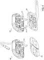
- each interface plate 204, 206has respectively four openings 310, 312 that are designed to receive corresponding drive shafts 314, 316.
- FIG. 4illustrates an underside perspective view of shafts 314, 316 attached to and extending from the pulley assemblies of the splayers 308, 306.
- a sheath instrument 104may include a sheath splayer 308 having drive shafts 314.
- Catheter instrument 106may include a guide splayer 306 having drive shafts 316.
- Drive shafts 316are each coupled to a respective motor within instrument driver 108 (motors not shown).
- 4-wire catheter 304is coupled to instrument driver 108, each drive shaft 316 thereof is thereby coupled to a respective wire 504-510, as shown in FIG. 5 .
- a distal end 502 of catheter 304can be articulated and steered by selectively tightening and loosening wires 504-510.
- the amount of loosening and tighteningis slight, relative to the overall length of catheter 304.
- each wire 504-510typically need not be tightened or loosened more than perhaps a few centimeters.
- the operator workstation 114may include a computer monitor to display a three dimensional object, such as an image 512 of a catheter instrument 304.
- Catheter instrument 304may be displayed within or relative to a three-dimensional space, such as a body cavity or organ, for example a chamber of a patient's heart or a femoral artery of a patient.
- an operatoruses a computer mouse to move a control point around the display to control the position of catheter instrument 304.
- a controller 400for manipulating/articulating a catheter 412 ( FIG. 6B ) may include a first control 406, a second control 408, and a third control 410.
- Each control 406, 408, 410may include a visual identifier, such as alphabetical letters A, B, and C, colors such as red, green, and blue, and/or the like, for convenience of the operator.
- visual display 404may depict an elongate member, such as a distal portion of a catheter 412 (or "catheter tip").
- the visual displayshows the distal portion of the catheter 412, with three pull wires 422, 424, 425 and a virtual indicator overlay displaying on the catheter 412.
- the virtual indicatoroverly includes three virtual indicators 414, 416, and 418 (or "graphic symbols"), which are arrows in the example shown but may be stacked bars or other direction indicators in other embodiments.
- Each of the virtual indicators 414, 416, and 418corresponds to one of the controls 406, 408, 410 and one of the pull wires 422, 424, 425.
- the image of the catheter 412may be an image acquired via any suitable medical imaging technique, such as but not limited to fluoroscopy, magnetic resonance imaging (MRI), ultrasonography, computed tomography (CT), or the like.
- the image of the catheter 412may be a computer generated image.
- the virtual indicators 414, 416, 418are computer-generated images overlaid onto the image of the catheter 412 to illustrate a commanded movement of the catheter 412, a measured movement of the catheter 412, a difference between the two, or some combination thereof.
- each of the virtual indicators 414, 416, 418corresponds to one of the controls 406, 408, 410 and also one of three pull wires 422, 424, and 426 configured to manipulate and/or steer the catheter 412.
- the virtual indicators 414, 416, 418 and the controls 406, 408, 410may be color coded to match one another.
- buttons and/or wiresmay be used.
- a cathetermay include 0 to 5 wires or 5 to 10 wires, or any subrange between those ranges.
- a catheterincludes 4 wires.
- a controllermay include 0 to 5 or 5 to 10 buttons or controls or any subrange between those ranges.
- a controllerincludes 4 buttons or controls.
- the button-to-wire ratioremains fixed throughout the procedure (e.g., 1:1 button to wire relationship).
- the visual display 404 and virtual indicators 414, 416, 418may show a commanded movement of the catheter 412, a measured movement of the catheter 412, a difference between the two, or some combination thereof.
- Communication movementor “commanded value” is intended to mean the direction (and in some embodiments the amount) of catheter movement directed by a user via the controls 406, 408, 410.
- Measured movementor “measured value” is intended to mean the direction (and in some embodiments the amount) of catheter movement measured by the system 100, for example via a sensor (or multiple sensors) on the catheter.
- the visual display 404may show a user the direction in which the catheter 412 has been commanded to articulate, an amount of commanded articulation in the commanded direction, and also a direction and amount of actual, measured articulation of the catheter. This type of information allows the user to see how the instructed/commanded movements have translated into actual/measured movements. As discussed further below in terms of several alternative embodiments, the visual display 404 may provide this information using any of a number of different types of visual indicators 414, 416, 418, such as arrows of different sizes and shapes, stacked bars having sizes and numbers corresponding to amounts of commanded articulation of a catheter, and the like.
- the overlay of indicators onto an image of a catheter to provide information about catheter movement to a usermay be very advantageous in providing an intuitive catheter driving experience for the user.
- the visual display 404 of the user interfacemay be configured to display information near the tip of the depicted catheter 412 so that the information stays within the operator's field of vision at all times of the procedure, unless turned off explicitly.
- a virtual representationmay overlay an imaged catheter 412 on the visual display 404 (e.g., a viewing screen), which includes virtual indicators 414, 416, 418 corresponding to visual identifiers disposed on the controls 406, 408, and 410.
- the visual display 404may illustrate which direction the catheter will articulate in response to actuating a control corresponding to the virtual indicator.
- the green arrowmay indicate the catheter will move radially in the depicted direction with respect to an axis in a plane of the visual display 404.
- a processormay be configured for generating the virtual representation of the catheter 412 using kinematic, FOSSL, electro-magnetic information, or imaging information acquired by computer vision techniques, for example, regarding the catheter.
- the processormay be configured to superimpose the virtual indicators 414, 416, 418 over the tip of the catheter 412.
- virtual indicators 414, 416, 418may overlay a fluoroscopic or like image of the catheter 412 inserted in the patient's anatomy, such that the visual display 404 shows the fluoroscopic image with the virtual indicator overlay to improve instinctive navigation of the catheter.
- the processormay be configured to adjust the virtual indicators 414, 416, 418 with corresponding movements of the catheter, such that the indicators 414, 416, 418 overlay the catheter 412 in proper position/orientation as the catheter 412 moves within the patient's anatomy. For example, if the catheter 412 rolls or twists during navigation, the virtual indicators 414, 416, 418 may adjust accordingly, such that the user always knows which wire to manipulate to drive the catheter 412 to the desired location in the vasculature.
- a non-transitory medium(not shown), storing a set of instructions may be configured to superimpose the virtual indicators 414, 416, 418 over a fluoroscopic image of the catheter 412.
- the instructionsmay additionally be operable to allow an operator to manipulate the catheter 412 via input from the controller 400.
- the instructionsmay be updated periodically to account for changes in catheter orientation and/or position, for example if the catheter 412 rolls or twists during navigation.
- the controller 400may include a planar input device, such as control buttons 406, 408, 410, as described above.
- the button-to-wire relationshipmay be fixed throughout the entire procedure, such that a particular button press may always cause a particular wire to be pulled-for example, pressing the green button will always pull the green wire, regardless of catheter orientation on the visual display 404.
- the controller 400may include three button controls 406, 408, and 410, corresponding to the three pull wires 422, 424, 425 in the catheter 412, for example as represented by the three virtual indicators 414, 416, and 418 as shown in FIG. 6B .
- the controller 400may optionally include a fourth control 420 configured to release or relax the pull wires 422, 424, 425 and thereby relax the catheter 412 to a straight position.
- each control buttonmay include two separate buttons, in which the inner button would release the pull wire associated with the controller and hence relax the catheter (e.g., relaxing red button would relax the red wire). The outer button would pull or tension the wire to articulate the catheter in the direction of the virtual indicator.
- the control buttons 406, 408, 410, and/or 420may be touch sensitive, such that the harder a button is pushed or the more force exerted on the button, the more the button will actuate, pull, or tension the corresponding pull wire 422, 424, 425. Thus, a button pushed fully to the base of the controller 400 may pull the corresponding wire to the maximum, so that the catheter 412 is articulated maximally in the direction of the pulled wire 422, 424, 425.
- control buttons 406, 408, 410may be combined or actuated simultaneously to articulate the catheter 412 in a direction that lies in between two pull wires 422, 424, 425.
- control buttons 406 and 408are pushed together, the system would pull wires 422 and 424, associated with indicators 414 and 416, thereby making the catheter 412 articulate in a direction between pull wires 422 and 424.
- a controller 426may include a control column or joystick 428 operable to gradually move about the base of the controller 426.
- the controller 426may include the joystick 428 and visual identifiers 430, 432, 434 on the controller 426 base, which indicate direction and/or corresponding virtual indicators and pull wires 422, 424, 425.
- the graphicsmay relate to the virtual indicators 414, 416, 418 on the visual display 404 as well as the pull wires 422, 424, 425 running through the catheter 412 to perform movements.
- the joystick 428can move gradually between adjacent buttons to mimic either single or simultaneous control button input, and the articulation direction of the catheter would thereby vary smoothly between wires.
- the joystick 428may be arranged concentrically with respect to the pie-shaped graphic drawing (e.g., analogous to the three button controller 400).
- the graphics 430, 432, and 434suggest which pull wire 422, 424, 425 will be pulled if the joystick 428 is moved in a particular direction.
- the joystick 428may include a return, for example a spring.
- the joystick 428may not be loaded with a return, which means the joystick 428 will not return to the center when external force is removed.
- the joystick 428may be a position control device that maintains its tilt or orientation when released or external force on the joystick is removed.
- the joystick 428 in a straight up, vertical, or perpendicular position relative to the controlsmay be equivalent to the catheter being fully relaxed, while the full forward position of the joystick (e.g., in relation to FIG.
- the joystick 428indicates the degree of effort the controller 426 attempts to effectuate catheter articulation. For example, if the joystick 428 is only slightly offset from center, then minimal effort may be exerted in pulling or tensioning the wire. Alternatively, if the joystick 428 is fully actuated, then full force may be exerted on the wire and the catheter 412 is maximally articulated, e.g., in the current environment. However, while the controller may exert maximum effort in attempting to articulate the catheter 412, the catheter 412 itself may not articulate, if there is an obstruction from the human anatomy and/or if the catheter 412 is experiencing roll or twist, for example.
- FIGS. 7A and 7Billustrate equivalent button and joystick control inputs that would cause a catheter 612 to articulate toward a red wire 622 ( Fig. 7A ) and in between the red wire 622 and a blue wire 624 ( Fig. 7B ).
- FIG. 7Ashows a catheter 612 responding to a single control button push or joystick movement in the direction of red 606 and consequently pulling or tensioning the red wire 622 represented by the red indicator 614, thereby articulating the catheter 612 in the direction of the large arrow 620.
- FIG. 7Billustrates the catheter 612 responding to a simultaneous red and blue button 606, 610 press or the joystick moving in between the red and blue 606, 610 graphics.
- Simultaneously actuating controls 606 and 610will trigger corresponding wires 622 and 624 (e.g., represented by virtual indicators 616, 618) to pull or tension, resulting in articulation of the catheter 612 in the direction of the large arrow 620.
- wires 622 and 624e.g., represented by virtual indicators 616, 618, to pull or tension, resulting in articulation of the catheter 612 in the direction of the large arrow 620.
- wires 622 and 624e.g., represented by virtual indicators 616, 618)
- an alternative embodimentmay involve a bend button and a rotate button with colors of the wires identified on the rotate button. In this example, the user would use the rotate button to orient with the required color and then press the bend button to bend in the required direction. This has the advantage of not requiring a bend button for each wire on the circumference of the catheter.
- a visual display 700, 720, 730may be used to illustrate movement of a catheter 702, for example to enhance instinctive navigation of the catheter 702.
- the visual display 700, virtual indicators 704, 706, 708are superimposed on a fluoroscopic image of the catheter 702, In order to easily identify which wire is controlled by which control (e.g., buttons or action of the joystick), identifiers for each wire are displayed near or superimposed onto the tip of the catheter.
- a red indicator 704, a green indicator 706, and a blue indicator 708are overlaid or superimposed onto three control wires 710, 712, and 714, respectively.
- the virtual overlay indicators 704, 706, 708likewise match the colors of the controls discussed above, indicating their one-to-one relationship (e.g., the control-to-wire relationship is fixed throughout the procedure, such that a particular control will always cause a particular wire to be pulled). Further, the indicators 704, 706, 708 are intuitive and easily distinguishable, so that the operator may immediately recognize the indicator 704, 706, 708 (and consequently the corresponding pull wire) upon glancing at it.
- a view of the cathetermay change during a procedure or use case.
- a catheter orientation or positionmay be indicated in a first or second view of the catheter using one or more methods, for example shading or coloring of the catheter based on the depth of the catheter into the viewing plane away from the user or 3-D viewing technology that may be manipulated (e.g., rotated, magnified) to view the catheter from one or more directions.
- the virtual indicatormay automatically change and update based on the current view.
- the virtual indicatorsmay be exchanged such that "green” still means left and “blue” still means right in a second view, for example if the catheter has rolled or twisted in the second view.
- the first viewmay be instinctive while the second view is not instinctive.
- a focus, gaze, or attention of a usermay be tracked, for example by a camera, to determine which view the user is using, such that the instinctiveness of the view relies on whether the user is using that particular view.
- the systemmay force the user to use, for example, only the first view as their primary view by either changing the size of the view or changing the on-screen indicators, such that first view is the instinctive view.
- the overlay virtual indicators 704, 706, and 708may be extended or enlarged to demonstrate the load on the wire (e.g., an amount or duration of force placed on the wire), which may serve as an important metric in determining whether the patient's anatomy is restricting movement. For example, the operator may compare the control effort (e.g., the magnitude of the virtual indicator) with the actual articulation amount of the catheter to determine if a patient's anatomy is restricting the movement of the catheter.
- the control efforte.g., the magnitude of the virtual indicator
- FIG. 8Billustrates another example, in which a visual display 720, uses stacked bar indicators 724, 726, 728, with variable magnitude representing differing wire loads.
- FIG. 8Cillustrates another example of a visual display 730, in which arrow indicators 724, 736, 738 have differing magnitudes representing differing wire loads. Either or both of the examples illustrated in FIGS. 8B and 8C may also be used with the example of the visual display 700 illustrated in FIG. 8A .
- a bar or arrow with greater magnituderepresents the load on the wire, which is correspondingly greater. Accordingly, the operator may thereby minimize unwanted damage to vessel walls by observing the changing magnitude of the virtual indicator and comparing the actual movement of the catheter.
- the operatormay conclude that the catheter is being restricted by the patient's anatomy.
- the user interfacemay be configured to provide a tactile feedback indicating that the catheter is being restricted by the patient's anatomy (e.g., the joystick vibrates upon being obstructed).
- the user interface 124may be configured to receive an operator input and command the movement of a virtual representation, e.g., a virtual indicator, overlaying an image of a flexible catheter, for example generated by a processor.
- a virtual representatione.g., a virtual indicator
- the virtual indicatordoes not represent the current articulation direction of the elongate member, but rather indicates which movement the catheter would make, if the motors/drivers where engaged, e.g., a predictive virtual representation.
- the predictive virtual indicatormay overlay or otherwise be superimposed over an actual image of the catheter (e.g., via medical imaging such as fluoroscopy, thermography, magnetic imaging, ultrasonography, computed tomography, positron emission tomography, etc.).
- the virtual indicatormay be aided in tracking the catheter in the image using computer vision techniques to process the image and determine the catheter location.
- FIGS. 9A and 9Btwo alternative examples of virtual indicator overlays 802, 822 on images 800, 820 of a distal portion of a catheter 808 are illustrated.
- the virtual indicator overlay 802is a graphic symbol including a bead 804 on a ring 806.
- the position of the bead 804 along the ring 806indicates a bend direction of the catheter 808, and the bead 804 may move around the circumference of the ring 806, as indicated by the double-pointed arrow.
- the image 820may include a virtual indicator overlay 822 that includes a ring 826 and an arrow 824.
- the arrow 824may indicate bend directionality in a way that is similar to that of the bead 804 and may similarly move around the circumference of the ring 826. In some examples, the arrow 824 may also grow and/or shrink in size to indicate the amount of commanded bending signal (e.g., the amount of bend commanded by the user via a user input). As shown in FIGS. 9A and 9B , the bead 804 or arrow 824 virtual indicator represents the direction the catheter 808 would articulate if the controller were engaged. Stated alternatively, the predictive virtual indicator 802, 822 uses available elongate member or catheter roll information to notify the operator of the imminent articulation direction before the elongate member 808 is articulated.
- the predictive virtual indicator overlay 802, 822may instruct the operator whether the catheter 808 is pointing into or out of the screen when the elongate member 808 is positioned in a plane perpendicular to the visual display 128. It can be very difficult to decipher whether the elongate member 808 is pointing into or out of the visual display 128.
- the direction in which the ring or arrow virtual indicator 822 rolls in relation to direction of the controller inputmay determine whether the elongate member 808 is pointing into or out of the screen in a plane perpendicular to the visual display 128.
- the bead 804 (or arrow 824 in an alternative embodiment) on the predictive indicator 802may roll in the opposite direction of the controller input if the elongate member 808 is pointed out of the visual display 128 (e.g., the elongate member 808 is facing towards the operator).
- FIG. 10Aillustrates the elongate member 808 pointing into the visual display when the predictive virtual indicator 804 rolls in the same direction as that of a joystick 838 (e.g., both roll clockwise).
- 10Billustrates the elongate member 808 pointing out of the visual display, because the predictive virtual indicator 804 rolls in a direction opposite of the joystick 838 (e.g., controller rolls clockwise and the predictive indicator rolls counterclockwise). Accordingly, the operator can easily decipher the heading of the elongate member 808 without actually articulating the elongate member 808 and thus potentially harming the patient's vasculature.
- the visual display 128may be in communication with a processor (not shown).
- the processormay generate the virtual indicator 802 overlaid on an actual image of a catheter 808 inserted into the patient's anatomy.
- the processormay be configured to adjust or manipulate the virtual indicator 802 to indicate which direction the catheter 808 would articulate if the controller were engaged.
- the processormay be operable to dynamically determine the desired articulation direction of the catheter (e.g., which wire(s) to pull/tension and which wire(s) to relax) based on the bead/arrow position on the virtual indicator 802.
- a non-transitory medium (not shown) storing a set of instructionsmay include one or more instructions to superimpose the virtual indicator 802 on the tip of the catheter 808 and one or more instructions for allowing the operator to rotate the virtual indicator 802 circumferentially around an axis. Additionally, the set of instructions may further include one or more instructions for allowing the user to manipulate multiple controls to move the catheter/elongate member 808, and may include a set of instructions for using kinematic information or sensor data (e.g., FOSSL, electromagnets), for example, to orient, position, and coordinate the virtual indicator 802 with the catheter 808.
- the virtual indicator 802therefore, advantageously uses available catheter 808 roll information to notify the operator of the imminent articulation direction before the catheter 808 actually articulates. Accordingly, the operator is encouraged or expected to interact with the virtual indicator 802 and visual display 128 to fine-tune the orientation of the virtual bead or arrow.
- the virtual indicator 802will show the actual movement of the catheter 808.
- the indicator 802not only shows the user how the catheter 808 will (or should) articulate before actual articulation, but it also shows the user how the catheter 808 actually articulates.
- the controller 844may include multiple controls, such as a first control 842 configured to roll/rotate the predictive indicator 606, a second control 846 configured to articulate the elongate member 608, and a third control 848 configured to relax the elongate member 608.
- the first control 842may include a control column or joystick.
- the first control 842may be a touch sensitive pad.
- the first control or joystick 842may be configured to rotate or roll while in the upright or vertical position which correspondingly controls the rotation of the bead or arrow on the ring of the virtual indicator.
- the joystick 842is a position controller and rotating the joystick 842 in the clockwise direction would roll the bead/arrow of the virtual indicator in the same direction (unless, however, if the elongate member is pointing out of the screen, in which case the bead/arrow would roll opposite the direction of the rotation of the joystick 842).
- the catheteris not actually “rotated” or “rolled” in response to a command to "rotate” or “roll,” but is progressively articulated using pull wires to mimic a rotational movement. For example, if a command is provided to articulate the catheter to the right, the system pulls or tensions a wire to articulate the catheter to the right.
- the systemunderstands that the bead/arrow has been rotated, and in response pulls or tensions another wire to articulate the catheter to the left.
- the systemmay dynamically decide which wire to pull/tension and relax based on the bead/arrow location on the virtual indicator.
- the catheterdoes not physically roll/rotate, but rather the virtual indicator rotates in the visual display.
- the system 100is configured to determine the articulation direction (and consequently the respective wire(s) to actuate and relax) in response to the position of the bead/arrow on the virtual indicator. Therefore, the system 100 reduces operator error and minimizes inadvertent touching of vessel walls.
- the joystick 842may likewise be configured to tilt forward and backward to command the elongate member to insert or retract, respectively. That is, the joystick 842 is a rocker switch but with added granularity allowing finer motion control.
- the joystick 842may be spring loaded so that the joystick 842 returns to its upright/vertical, middle position when no external force is applied.
- the control inpute.g., tilting for insert/retract and/or the rate of return back to the middle position
- the control inputmay be mapped to the rate of increase or decrease as in velocity control. For example, tilting the joystick 842 fully forwards or backwards may insert/retract the elongate member at a greater velocity than slightly tilting the joystick.
- the rate at which the joystick 842 returns without external forcemay be a constant velocity.
- the controller 844may likewise include multiple push controls, for example a second control 846 and a third control 848.
- the second control 846may be configured to articulate the elongate member
- the third control 848may be configured to relax the elongate member (e.g., an articulation button and a relax button).
- pressing the second control 846 buttonwill physically articulate the elongate member in the set direction.
- the elongate membermay continue to articulate until the force is lifted from the first control 842 (e.g., until the operator releases the articulate button).
- pressing and holding the third control 848will gradually relax the elongate member back to its straight configuration.
- the elongate membermay remain in its articulated configuration until the third control 848 is pressed to relax the elongate member.
- an alternative example of a controller 904may include a joystick 910, a bend button 912, a relax button 914, a roller 916 and a light feature 918.
- the roller 916(or "fourth control") may act as a locking feature (or alternatively another form of failsafe mechanism in alternative examples), to ensure there is no accidental activation of roll or insertion activities.
- the roller 916may be operable to rotate and correspondingly rotate the bead/arrow virtual indicator.
- the joystick 910may be configured to move forward and backward for insertion and retraction, respectively.
- the joystick 910may be configured as a toggle button, in which the entire joystick 910 can be pushed down from the top to either activate or deactivate the locking feature.
- the roller 916With the roll lock enabled, the roller 916 may still be operable to rotate but without having any effect on the virtual indicator, and hence no change in articulation direction. However, even with the locking feature, the roller 916 may still be used for combining the insertion and roll of the elongate member (e.g., simultaneous actions) by merely disabling/deactivating the lock feature.
- the controller 904 basemay also include the light feature 918 or other indicator, for example a circular area around the base of the controller 904 embedded with different colors to indicate whether the lock has been enabled.
- FIG. 13illustrates an image of a dome 920 at a distal end of the elongate member 908.
- the dome 920may represent a constraint for the catheter 908 tip so that at least part of the catheter 908 tip is required to be on a surface of the dome 920 regardless of how the catheter 908 is driven.
- the catheter tip motionis confined to a surface of the virtual dome 920 created around a base 922 of its articulation section 924, and a 3D joystick (not shown), for example, would navigate the catheter tip around the dome's surface.
- the circumference of the dome 920may expand depending on the exposed length of the catheter's articulation section (e.g., a telescoping catheter). Alternatively, the full length of the articulation section may be used to set the size of the dome 920.
- a virtual ring 926may be a projection of the catheter tip onto the dome 920 surface and the bead/arrow 928 indicates which direction the ring would move if the controller were engaged. Accordingly, the virtual indicator 906 is always on the dome 920 surface. Pressing the articulation button as described above would move the catheter 908 tip in the direction towards the bead/arrow 928 along the dome 920 surface.
- FIG. 14Aillustrates a response of the catheter 1008 when the virtual indicator 1006 is rolled ninety (90) degrees in clockwise direction prior to the user pressing the articulation button.
- the direction of rotationin this example, is from the perspective of inside of the catheter 1008. An observer outside the catheter 1008 would view this rotation as appearing counter clockwise.
- the articulation buttonis pressed, the ring 1026 moves along the surface of the dome 1020 following the direction of the bead 1028. If the virtual indicator 1006 is rolled forty five (45) degrees more, pressing the articulation button would initially roll and relax the catheter 1008 at the same time, but the catheter 1008 would eventually articulate away from the user, for example as shown in FIG. 14B . This can be seen in FIG.
- the catheter 1008relaxes as the tip or ring 1026 straightens and moves towards the top of the dome 1020, but the articulating angle subsequently increases as the ring 1026 moves further way from the dome 1020 apex.
- the relax control buttonmay be redundant as the operator can always roll the indicator 1006 a hundred and eighty (180) degrees and press the articulation button to relax the catheter 1008.
- the separate control buttonmay make it easier to access this important function, as pressing relax would always bring the catheter 1008 tip back to the top of the dome 1020 following the shortest path regardless of roll and articulation.
- FIG. 15Aillustrates a controller 1100 according to another example.
- the controller 1100may have a roll knob 1102, four control buttons for articulating 1104, relaxing 1106, inserting 1108, and retracting 1110.
- the controller 1100 illustrated in FIG. 15Bis similar in that the roll knob 1102 is the same, but the right and left buttons would be disabled such that the up/down buttons may be used for articulating and relaxing, respectively.
- a switch or slider 1112may be operable to move back and forth for inserting and retracting.
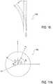
- a catheterwas presumed to not rotate or roll around its axis as it advances through the vasculature. However, this presumption is not true in reality. For example, as shown in FIG. 16 , a distal section of a catheter 808 is illustrated with a 180 degree twist. When the controller desires to articulate the catheter to the right, it pulls the wire on the right side of the catheter 808. However, instead of articulating to the right, the catheter 808 may articulate to the left because of the roll or twist experienced by the catheter 808. Previously, the controller could not make proper adjustments to correct the action because there was no concept of catheter roll. However, as will be described in further detail below, a roll sensor may be used to enable roll compensation and correction.
- a roll sensorhas the potential to improve the catheter driving experience by enabling the controller adapt to the inevitable twist or roll in the catheter shaft as it is navigated through the vasculature.
- the controllermay change an amount of wire pull or tension based on the roll angle in order to articulate the catheter tip in the desired direction. In some embodiments, this is achieved by altering the desired articulation direction by the measured roll amount.
- FIGS. 17A and 17Bwhen an articulation command is initiated, the controller first computes the moment required to articulate the catheter tip and then calculates how much to pull or tension the wire to generate the moment.
- FIGS. 17A and 17Bshow moments and various angles involved in the computation. If M is the desired moment and m; is the moment generated from pulling the i th wire in the catheter, the following equation describes how the desired moment is related to the moments resulting from wire pulls.
- ⁇is the direction of the moment M
- ⁇ iis the direction of the moment resulting from the i th wire pull.
- the ⁇ iis related to the angular position of the i th wire, ⁇ i , by a fixed amount ⁇ /2.
- the measured roll angle, ⁇is subtracted out from the original articulating moment direction ⁇ to compensate for the roll.
- FIGS. 18A - 23Billustrate systems and methods for integrating a magnetic encoder into a catheter for measuring its roll. These FIGS. 18A-23B are illustrated from the perspective of being inside of the catheter-e.g., as if a camera were inside the catheter and looking out through an opening in the distal tip of the catheter.
- the instrumented catheterwould enhance the instinctive driving experience by further improving the accuracy of catheter control.
- FIGS. 18A and 18Billustrate a case where ⁇ is ⁇ /2, which means the distal tip of the catheter rolled 90 degrees in the counter clockwise direction. The rotation is around the z-axis, which points out of the screen according to the right hand rule, i.e. cross x-axis and y-axis to get the z-axis.
- one or more encoders 1201may be used to measure catheter roll and thus improve instinctive driving.
- encodersare non-contact sensors with an infinite number of turns.
- Encoderscome in optical and magnetic varieties.
- the optical encoderuses an optical emitter-detector pair with a patterned encoder wheel in between to detect the amount of rotation.
- a magnetic encoder 1201shown in FIGS. 19A and 19B , uses a Hall-effect or magneto-resistive sensor 1202 to detect changes in polarity.
- a magnetized ring 1200is used to provide the alternating magnetic poles along the circumference of the ring 1200.
- the Hall-effect sensor 1202can detect the change in polarity as the ring 1200 turns, and the sensor 1202 produces electric pulses for angular measurements.
- a magnetic encoder 1201measures relative roll between the magnetic ring 1200 and the Hall-effect sensor 1202, i.e. the read head.
- the sensor 1202is fixed to a stationary object, and the magnetized ring 1200 rotates with the spinning object or vice versa.
- the magnetic ring 1200 and the sensor 1202may be incorporated into a catheter 1220, which may also include a distal catheter tip 1204, two rings 1208a, 1208b on either side of the ring 1200, a control ring 1206 and control wires 1210.
- the magnetic ring 1200functions to rotate whenever the catheter 1220 rolls, so that the Hall-effect sensor 1202 can detect the change in roll.
- the ring 1200is mounted on rails 1208a, 1208b on both sides to allow it to spin around freely as the catheter 1220 rolls, and the sensor 1202 is fixed and embedded into the catheter wall.
- the control ring 1206provides soldering points for the control wires 1210.
- the control ring 1206 and the proximal rail 1208bmay be combined into a single ring to simplify catheter construction, and the control wires 1210 may be directly soldered to the proximal rail 1208b.
- a fluid bearingrather than a mechanical bearing may be used to enable the ring 1200 to freely rotate under gravitational pull in the case in which the rails 1208a, 1208b cannot significantly reduce friction.
- the magnetized ring 1200may be enclosed in a sealed, tube-like structure filled with low viscosity fluid to lower the friction.
- the operation of the Hall-effect sensor 1202would not be affected, because it does not need to be in direct contact with the ring 1200.
- small-scale ditheringmay be used to constantly break friction.
- a sound wave or any other type of external excitation signalmay be used to excite the ring 1200 to break free from either the rail 1208a, 1208b or the fluid bearing.
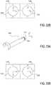
- a ring 1230may be constructed with unbalanced weight distribution, so that it stays upright regardless of catheter roll.
- the ring 1230is heavy on one side and light on the other side.
- the ringmay rotate independently to keep the heavy side down consistently.
- the size of an enclosing oval 1232as shown in FIG. 21A , demonstrates the weight distribution in the ring 1230.
- the weightgradually increases from the top side of the ring to the bottom side of the ring 1230, as designated by the double-headed arrow.
- the weight distributionmay change abruptly.
- a discontinuous weight changefor example extra weight hanging from one side of the ring 1230, may maintain the ring 1230 stay upright consistently.
- a roll sensormay improve the control and navigation of a robotic catheter.
- the controllermay be able to interpret user inputs quickly, based on the measured roll information and adjust its control output accordingly to increase instinctive driving of the catheter.
- the cathetermay be articulated in the direction desired by the user with all the computation hidden from the user.
- a roll sensormay be used for navigation with direct visualization.
- a cameramay be installed on the distal end or tip of a catheter to directly provide a visual image of the surroundings during navigation.
- U.S. Patent Application Serial No. 13/452,029U.S. Pub. No. 2012/0296161
- U.S. Pub. No. 2012/0296161filed April 20, 2012 , has further information regarding a method to obtain a clear viewing field for a camera.
- a roll sensormay measure the absolute roll of the catheter and may be applied to a non-telescoping catheter. If the catheter is instrumented with a camera, the roll sensor can help reorient the camera view so that it displays the field of view right side up. For example, the camera view may not rotate even if the camera itself rotates, and one or more catheter controls may compensate for the catheter roll so that the catheter is manipulated instinctively under the endoscopic camera view.
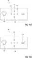
- FIGS. 22A and 23Aillustrate a catheter 1240 from the viewpoint of a user.
- the catheter 1240is equipped with a camera 1242 at its distal tip and a roll sensor 1244 just proximal to the camera 1242.
- FIG. 23Aillustrates the catheter 1240 rolling 90 degrees in a counter clockwise direction (flat, curved arrow).
- FIGS. 22B and 23Billustrate a left viewing screen 1246 and a right viewing screen 1248, which display images 1250, 1252, 1254, 1256 to the user to assist in manipulation of the catheter 1240.
- the image 1254 on the left screen 1246is an uncompensated view
- the image 1256 on the right screen 1248is a compensated view (e.g.
- the catheter controllermay recognize the change in roll and make proper adjustments to facilitate navigation. This is illustrated as the D instead of R in the right image 1256 in FIG. 23B .
- pulling the R wirewould articulate the catheter 1240 to the right.
- the controllerneeds to pull the D wire instead of the R wire to articulate the catheter 1240 to the right.
- This modification in control algorithmis transparent to the user, and the controller would make the proper adjustment based on the roll measurement.
- a magnetic encoder and sensormay be placed respectively on components of a telescoping catheter, such that relative roll between inner and outer components of the telescoping catheter can be determined.
- a roll sensormay provide relative roll measurements between the camera, and therefore the instrumented balloon catheter, and the guide catheter.
- this embodimentuses a relative roll measurement, ⁇ , to obtain a new articulating direction ⁇ t . This new articulation direction makes navigation intuitive from the camera's perspective.
- ⁇measures the roll of the guide catheter with respect to the camera.
- ⁇ t⁇ ⁇ ⁇
- the relative roll measurement, ⁇is zero; likewise, if the camera rolls ⁇ /2 counter clockwise, it is equivalent to the guide catheter roll of - ⁇ /2 counter clockwise.
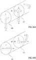
- FIGS. 24A and 24Billustrate a case where the camera is rolled 90 degrees but the catheter roll remains unchanged.
- the front image in FIGS. 24A and 24Bis a camera view
- the back image in FIGS. 24A and 24Bis a catheter view.
- FIGS. 25A and 25Ba simulated usage of a catheter-based system 1300 for navigating and performing a procedure in a blood vessel is illustrated.
- the system 1300is shown advanced through a blood vessel BV toward a branching of the vessel BV into a left branch LB and a right branch RB.
- the system 1300in this embodiment, includes a guide catheter 1302 and an instrumented balloon catheter 1304, which includes a distal tip camera 1310 and a balloon 1306.
- the systemincludes roll compensation, as disclosed herein.
- An image 1320( FIG. 25B ) may be provided, for example to show directionality of the camera 1310, such as a camera-up arrow 1312.
- the user interfacemay use a computer or a computer readable storage medium implementing the operation of drive and implementing the various methods described herein.
- computing systems and/or devicessuch as the processor and the user input device, may employ any of a number of computer operating systems, including, but by no means limited to, versions and/or varieties of the Microsoft Windows® operating system, the Unix operating system (e.g., the Solaris® operating system distributed by Oracle Corporation of Redwood Shores, California), the AIX UNIX operating system distributed by International Business Machines of Armonk, New York, the Linux operating system, the Mac OS X and iOS operating systems distributed by Apple Inc. of Cupertino, California, and the Android operating system developed by the Open Handset Alliance.
- the Unix operating systeme.g., the Solaris® operating system distributed by Oracle Corporation of Redwood Shores, California
- AIX UNIX operating systemdistributed by International Business Machines of Armonk, New York
- the Linux operating systemthe Mac OS X and iOS operating systems distributed by Apple Inc. of Cupertino
- Computing devicesgenerally include computer-executable instructions, where the instructions may be executable by one or more computing devices such as those listed above.
- Computer-executable instructionsmay be compiled or interpreted from computer programs created using a variety of programming languages and/or technologies, including, without limitation, and either alone or in combination, JavaTM, C, C++, Visual Basic, Java Script, Perl, etc.
- a processore.g., a microprocessor
- receives instructionse.g., from a memory, a computer-readable medium, etc., and executes these instructions, thereby performing one or more processes, including one or more of the processes described herein.
- Such instructions and other datamay be stored and transmitted using a variety of computer-readable media.
- a computer-readable mediumincludes any non-transitory (e.g., tangible) medium that participates in providing data (e.g., instructions) that may be read by a computer (e.g., by a processor of a computer).
- a mediummay take many forms, including, but not limited to, non-volatile media and volatile media.
- Non-volatile mediamay include, for example, optical or magnetic disks and other persistent memory.
- Volatile mediamay include, for example, dynamic random access memory (DRAM), which typically constitutes a main memory.
- Such instructionsmay be transmitted by one or more transmission media, including coaxial cables, copper wire and fiber optics, including the wires that comprise a system bus coupled to a processor of a computer.
- Computer-readable mediainclude, for example, a floppy disk, a flexible disk, hard disk, magnetic tape, any other magnetic medium, a CD-ROM, DVD, any other optical medium, punch cards, paper tape, any other physical medium with patterns of holes, a RAM, a PROM, an EPROM, a FLASH-EEPROM, any other memory chip or cartridge, or any other medium from which a computer can read.
- Databases, data repositories or other data stores described hereinmay include various kinds of mechanisms for storing, accessing, and retrieving various kinds of data, including a hierarchical database, a set of files in a file system, an application database in a proprietary format, a relational database management system (RDBMS), etc.
- Each such data storeis generally included within a computing device employing a computer operating system such as one of those mentioned above, and are accessed via a network in any one or more of a variety of manners.
- a file systemmay be accessible from a computer operating system, and may include files stored in various formats.
- An RDBMSgenerally employs the Structured Query Language (SQL) in addition to a language for creating, storing, editing, and executing stored procedures, such as the PL/SQL language mentioned above.
- SQLStructured Query Language
- system elementsmay be implemented as computer-readable instructions (e.g., software) on one or more computing devices (e.g., servers, personal computers, etc.), stored on computer readable media associated therewith (e.g., disks, memories, etc.).
- a computer program productmay comprise such instructions stored on computer readable media for carrying out the functions described herein.
Landscapes
- Health & Medical Sciences (AREA)
- Life Sciences & Earth Sciences (AREA)
- Engineering & Computer Science (AREA)
- Surgery (AREA)
- Heart & Thoracic Surgery (AREA)
- Biomedical Technology (AREA)
- Animal Behavior & Ethology (AREA)
- General Health & Medical Sciences (AREA)
- Public Health (AREA)
- Veterinary Medicine (AREA)
- Medical Informatics (AREA)
- Molecular Biology (AREA)
- Nuclear Medicine, Radiotherapy & Molecular Imaging (AREA)
- Robotics (AREA)
- Biophysics (AREA)
- Human Computer Interaction (AREA)
- Pathology (AREA)
- Physics & Mathematics (AREA)
- Radiology & Medical Imaging (AREA)
- Pulmonology (AREA)
- Anesthesiology (AREA)
- Hematology (AREA)
- Endoscopes (AREA)
- Magnetic Resonance Imaging Apparatus (AREA)
Description
- The present disclosure relates generally to a robotic surgical system, and more particularly to systems and devices for improving instinctive control of catheter movement in a patient's anatomy.
- Robotic surgical systems and devices are well suited for use in performing minimally invasive medical procedures, as opposed to conventional techniques that may require large incisions to open the patient's body cavity to provide the surgeon with access to internal organs. Advances in technology have led to significant changes in the field of medical surgery, such that less invasive surgical procedures, in particular minimally invasive surgery (MIS) procedures, are increasingly popular.
- MIS is generally defined as surgery that is performed by entering the body through the skin, body cavity, or an anatomical opening, using small incisions rather than large, open incisions in the body. With MIS, it is possible to reduce operative trauma to the patient, hospitalization time, pain and scarring, incidence of complications related to surgical trauma, costs, and recovery time.
- Special medical equipment may be used to perform an MIS procedure. Typically, a surgeon inserts small tubes or ports into a patient and uses endoscopes or laparoscopes having a fiber optic camera, light source, and/or miniaturized surgical instruments. A robotic catheter system attempts to facilitate this process by controlling the catheter tip with better precision and improved instinctive control. The goal of instinctive driving of a catheter or other elongate member is to move the catheter tip as the operator intends when the catheter is manipulated and observed by the operator remotely. For example, the orientation of the model image of the catheter is adjusted to match that of a real image of the catheter, so that a command to move the model catheter to the right results in the actual catheter tip moving to the right in the reference frame of the real image of the catheter.
- However, current user interface tools and user interface devices still lack features that facilitate instinctive driving. For example, a user may desire to navigate a catheter to the right, but it may be unclear to the user which pullwire should be manipulated, especially if the catheter is experiencing some degree of roll or twist. Further, correcting or accounting for roll or twist poses challenges to instinctive driving. For example, it may not be apparent to the user if roll has occurred or what direction the catheter tip will head in after catheter roll has occurred.
- In some cases, sensorizing the catheter may facilitate instinctive driving. For example, Fiber Optic Shape Sensing and Localization (FOSSL) or electromagnetic sensing may be used to sense the shape of a flexible body, such as the catheter during an MIS procedure, to permit visualization of the catheter in the patient's anatomy. The catheter position and orientation may be transmitted to a visual display to allow an operator (e.g., a surgeon) to analyze the images and make decisions to navigate through the patient's anatomy instinctively. However, this process is not straightforward and generally requires the operator to interpret multiple two-dimensional images acquired in real time (e.g., fluoroscopic images) in three-dimensional space before engaging in catheter manipulation.
- Accordingly, there is a need for systems and methods to identify and/or correct catheter roll and to simplify user interface commands for more intuitive controls in order to facilitate navigation through a patient's anatomy.
US2011/196199 describes a robotic endoscope system in which the orientation of a captured camera view at a distal tip of the endoscope and displayed on a screen viewable by an operator of the endoscope is automatically maintained at an orientation associated with a setpoint so as not to disorientate the operator as the endoscope is moved, flexed and its tip turned in different orientations. A processor generates a current commanded state of the tip from operator input and modifies it to maintain the setpoint roll orientation. To generate the modified current commanded state, the current commanded roll position and velocity are constrained to be a modified current commanded roll position and velocity that have been modified according to a roll angular adjustment indicated by a prior process period commanded state of the tip and the setpoint. The processor then commands the robotic endoscope to be driven to the modified commanded state.- The present invention is set out in the appended claims.
- In one example, a robotic catheter system may include: a flexible catheter having a proximal end, a distal end, and an articulating portion at the distal end; a sensor coupled with the flexible catheter at or near the distal end; a visual display for displaying an image of at least part of the flexible catheter; a processor for generating a virtual indicator displayed on the image of the flexible catheter, where the virtual indicator indicates a direction of articulation and/or an amount of articulation of the articulating portion of the catheter; and a controller coupled with the proximal end of the flexible catheter to receive a user input and articulate the articulating portion of the catheter in response to the user input.
- In some examples, the controller may include a first control configured to receive an additional user input and rotate the virtual indicator about a longitudinal axis of the catheter in response to the additional user input, without rotating the catheter. For example, the first control may be a control column configured to rotate about an axis relative to a base of the controller, where rotation of the virtual indicator corresponds to rotation of the control column. In some examples, for example, rotating the control column in a clockwise direction rotates the virtual indicator in a clockwise direction when the elongate member points into the visual display, and rotating the control column in the clockwise direction rotates the virtual indicator in a counterclockwise direction when the elongate member points out of the visual display. Optionally, the system may further include an actuator coupled to the catheter for articulating the articulation portion, and the controller may include a second control coupled to the actuator for articulating the articulation portion.
- In some examples, the virtual indicator corresponds to the controller, and inputting a user input into the controller causes the processor to generate the virtual indicator indicating a direction of movement of the articulation portion of the flexible catheter. In some examples, the virtual indicator corresponds to an actuator coupled to the catheter, and engaging the actuator articulates the articulating portion in a direction of the virtual indicator. In some examples, the virtual indicator may include a first graphic symbol corresponding to a first actuator coupled to the flexible catheter, a second graphic symbol corresponding to a second actuator coupled to the flexible catheter, and a third graphic symbol corresponding to a third actuator coupled to the flexible catheter. These graphic symbols may be equally spaced along a circumference of the image of the flexible catheter displayed on the visual display. In various examples the graphic symbols may be arrows, stacked bars or a combination of both.
- In some examples, the controller may include multiple controls corresponding to the graphic symbols and coupled to the actuators, and engaging a first control articulates the elongate member in a direction of the first graphic symbol, engaging a second control bends the elongate member in a direction of the second graphic symbol, and engaging a third control bends the elongate member in a direction of the third graphic symbol. In some examples, engaging the first control and the second control simultaneously articulates the articulating portion of the flexible catheter in a direction between the first and second graphic symbols. In some examples, the controls and corresponding graphic symbols are color coded. In some examples, each of the graphic symbols is configured to change in size in proportion to an amount of articulation of the flexible catheter in a direction of the graphic symbols.
- In various alternative, the virtual indicator may include at least one graphic symbol, such as but not limited to one or more arrows, stacked bars, ring-and-bead symbols, and/or ring-and-arrow symbols. In some examples, the controller includes a joystick. In some embodiments, the processor is configured to track the flexible catheter in the image using computer vision techniques. In such embodiments, the processor may be operable to overlay the virtual indicator on the image in response to tracking information.
- An exemplary method for facilitating a robotic catheter procedure may involve generating, via a processor, a virtual indicator on a visual display, and overlaying the virtual indicator onto an image of at least an articulating portion of a flexible catheter used in the robotic catheter procedure on the visual display. The virtual indicator represents a direction of articulation and/or an amount of articulation of the articulating portion of the flexible catheter. In some examples, the method may further involve providing a user input device for receiving user inputs to control articulation of the articulating portion of the flexible catheter, where the user input device corresponds to the virtual indicator. Some examples may further involve manipulating the virtual indicator in response to a first user input, where the virtual indicator rotates about a longitudinal axis of the flexible catheter. Optionally, the method may also include articulating the flexible catheter in the direction of the virtual indicator, in response to a second user input.
- In various alternative examples, the virtual indicator may include at least one graphic symbol, such as but not limited to an arrow, stacked bars, a ring-and-bead, and/or a ring-and-arrow. In some examples, the virtual indicator correlates to an actuator coupled to the flexible catheter. Some examples may also include engaging the actuator to articulate the articulating portion of the flexible catheter in the direction of articulation. Some examples may also include changing a size of the virtual indicator in response and in proportion to an amount of articulation of the articulating portion of the flexible catheter in the direction of articulation. Optionally, the method may also include tracking the flexible catheter in the image, using computer vision techniques, to generate tracking information, where the tracking information is used to overlay the virtual indicator on the image flexible catheter. The method may also optionally include registering the image of the flexible catheter with a fluoroscopic image of the flexible catheter to generate registration information, where the registration information is used to overlay the virtual indicator on the image.
- These and other aspects and embodiments of the disclosure are described in greater detail below, in relation to the attached drawing figures.
- While the claims are not to be limited to the illustrated examples, an appreciation of various aspects is best gained through a discussion of various examples thereof. Referring now to the drawings, illustrative examples are shown in detail. Although the drawings represent the exemplary illustrations, the drawings are not necessarily to scale and certain features may be exaggerated to better illustrate and explain an innovative aspect of a given example. Further, the exemplary approaches described herein are not intended to be exhaustive or otherwise limiting or restricting to the precise form and configuration shown in the drawings and disclosed in the following detailed description. Exemplary illustrations of the present invention are described in detail by referring to the drawings as follows:
FIG. 1A is a perspective view of a robotically controlled surgical system, according to one embodiment;FIG. 1B is a magnified perspective view of a user interface having a controller and visual display of the robotically controlled surgical system ofFIG. 1A ;FIG. 2 is a perspective view of an exemplary catheter assembly of the surgical system ofFIG. 1A ;FIGS. 3 and4 perspective views of components of the catheter assembly ofFIG. 2 ;FIG. 5 a perspective view of a distal end of an exemplary catheter that is controllable by internal control elements, according to one embodiment;FIG. 6A is a top view of a controller with button controls, according to one example;FIG. 6B is a perspective view of a catheter with a virtual indicator overlay, according to one example;FIG. 6C is a top view of a controller with a joystick control, according to an alternative example;FIG. 7A is a perspective view of an articulating distal portion of a catheter and top views of the controllers ofFIGS. 6A and 6C , illustrating user input corresponding to the articulation of the distal portion, according to one example;FIG. 7B is a perspective view of an articulating distal portion of a catheter and top views of the controllers ofFIGS. 6A and 6C , illustrating user input corresponding to a different direction of articulation of the distal portion, according to one example;FIG. 8A is a perspective view of a catheter with a virtual indicator overlay, according to one example;FIG. 8B is a perspective view of a catheter with a virtual indicator overlay having a stacked bar configuration, according to an alternative example;FIG. 8C is a perspective view of a catheter with a virtual indicator overlay having arrows with variable magnitude, according to another alternative example;FIG. 9A is a perspective view of a distal portion of a catheter with a virtual indicator overlay having a ring-and-bead configuration, according to one example;FIG. 9B is a perspective view of a catheter with a virtual indicator overlay having a ring-and-arrow configuration, according to an alternative example;FIG. 10A a perspective view of a distal portion of a catheter arranged perpendicular to a plane of the visual display pointing into the visual display, and a side view of a joystick controller, illustrating its motion corresponding to the motion of the distal portion of the catheter, according to one example;FIG. 10B a perspective view of a distal portion of a catheter arranged perpendicular to a plane of the visual display pointing out of the visual display, and a side view of a joystick controller, illustrating its motion corresponding to the motion of the distal portion of the catheter, according to one example;FIGS. 11A and 11B are perspective and side views, respectively, of a controller of the user interface ofFIG. 1B , according to one example;FIG. 12 is a perspective view of a controller of the user interface ofFIG. 1B , according to an alternative example;FIG. 13 illustrates a distal portion of a catheter with a virtual dome constraining the motion of the catheter, according to one example;FIGS. 14A and 14B illustrates the motion of the distal portion of the catheter enclosed by the virtual dome ofFIG. 13 ;FIGS. 15A and 15B are top views of a controller of the user interface ofFIG. 1B , according to another alternative example;FIG. 16 is a side view of a distal portion of a catheter, illustrating an effect of distal roll on a catheter with 180 degrees twist;FIGS. 17A and17B are end-on and perspective views, respectively, of a distal portion of a catheter, illustrating moments of movement on a catheter tip, according to one embodiment;FIGS. 18A and18B are end-on views of a distal portion of a catheter, illustrating roll compensation for no roll and 90 degrees roll, respectively, according to one embodiment;FIGS. 19A and 19B are perspective and end-on views, respectively, of a magnetic encoder that uses a Hall-effect or magneto-resistive sensor to detect changes in polarity, according to one embodiment;FIGS. 20A and 20B are exploded and assembled/side views, respectively, of a distal portion of a catheter including the magnetic encoder components ofFIGS. 19A and 19B , according to one embodiment;FIGS. 21A and21B are end-on views of a magnetic ring of a magnetic encoder, illustrating asymmetrical weight of the ring, according to one embodiment;FIG. 22A is a perspective view of a distal portion of a catheter with a distal tip camera, according to one embodiment;FIG. 22B is a front view of two video displays illustrating image representations of the catheter ofFIG. 22A , illustrating what a user would see on the screen when the catheter is equipped with a camera for zero degrees roll;FIG. 23A is a perspective view of a distal portion of a catheter with a distal tip camera, according to one embodiment;FIG. 23B is a front view of two video displays illustrating image representations of the catheter ofFIG. 23A , illustrating what a user would see on the screen when the catheter is equipped with a camera for 90 degrees roll;FIGS. 24A and 24B are perspective diagrammatic representations of a distal end of a catheter, illustrating roll compensation for no camera roll and 90 degrees camera roll, respectively, according to one embodiment; andFIGS. 25A and 25B are perspective and end-on views of a catheter system, illustrating a simulated usage of a camera and a guide catheter.- Referring now to the drawings, illustrative embodiments are shown in detail. Although the drawings represent the embodiments, the drawings are not necessarily drawn to scale, and certain features may be exaggerated to better illustrate and explain innovative aspects of an embodiment. Further, the embodiments described herein are not intended to be exhaustive or otherwise limit or restrict the invention to the precise form and configuration shown in the drawings and disclosed in the following detailed description.
- The disclosure describes systems and devices for improving instinctive driving of an elongate member, for example a flexible catheter. As described herein, a user interface may be configured to take advantage of catheter orientation information, such as roll and/or articulation, to provide a more intuitive controller to navigate the tortuosity of the vasculature. That is, the user interface may use information acquired from sensors, such as electro-magnetic sensors embedded into the catheter, and/or fiber optic sensors that may run the length of the catheter (e.g., FOSSL), for virtual representation of the position and orientation of the catheter within the patient's anatomy. In some embodiments, sensors may be used to determine and control catheter roll or twist to facilitate instinctive manipulation of a catheter as it is navigated through a patient's anatomy. A user interface may also use information acquired from the imaging system (e.g., such as fluoroscopy) via computer vision techniques. The disclosed user interface and roll control may take advantage of the received information to provide more intuitive commands to facilitate navigation through the patient's anatomy.
- Referring now to
FIG. 1A , a robotically controlledsurgical system 100 may include arobotic catheter assembly 102 having a robotic or first or outer steerable component, otherwise referred to as a sheath instrument 104 (generally referred to as "sheath" or "sheath instrument") and/or a second or inner steerable component, otherwise referred to as a robotic catheter or guide or catheter instrument 106 (generally referred to as "catheter" or "catheter instrument").Catheter assembly 102 is controllable using a robotic instrument driver 108 (generally referred to as "instrument driver"). During use, a patient is positioned on an operating table or surgical bed 110 (generally referred to as "operating table") to whichrobotic instrument driver 108 is coupled or mounted via asetup mount 112.Setup mount 112 may likewise include a rail system (not shown) configured to allow thesetup mount 112 to translate along the length ofsurgical bed 110, and a motorized rail, (e.g., rail shark fin illustrated as the triangular plate) configured to tilt theinstrument driver 108. As shown inFIG. 1A ,system 100 includes anoperator workstation 114, anelectronics rack 116, aguide wire manipulator 118, and an associatedbedside electronics box 120, andinstrument driver 108. A surgeon is seated atoperator workstation 114 and can monitor the surgical procedure, patient vitals, and control one or more catheter devices. - System components may be coupled together via multiple cables or other
suitable connectors 118 to provide for data communication, or one or more components may be equipped with wireless communication components to reduce or eliminatecables 118. Communication between components may also be implemented over a network or over the Internet. In this manner, a surgeon or other operator may control a surgical instrument while being located away from or remotely from radiation sources, thereby decreasing radiation exposure. Because of the option for wireless or networked operation, the surgeon may even be located remotely from the patient in a different room or building. - The
workstation 114 may include auser interface 124 configured to receive user inputs to operate various components or systems of thesurgical system 100. Theuser interface 124 may include acontroller 126 to enable the operator to control or manipulate therobotic catheter assembly 102. For instance, thecontroller 126 may be configured to cause the catheter to perform various tasks and/or movements (e.g., insert, retract, rotate, articulate, etc.). Thecontroller 126 may be operable to allow the operator to navigate the catheter through the patient's anatomy via articulating the distal tip of the steerable catheter. - In some embodiments, the
controller 126 may include a planar input (e.g., a joystick) and surrounding dedicated buttons configured to insert, retract, rotate, and articulate the guide wire and/or catheter, as discussed below. Additionally or alternatively, thecontroller 126 may include a touch screen configured to display icons corresponding to catheter and/or guide wire movements (e.g., insert, retract, roll, articulate, inflate/deflate a balloon or stent, etc.). Thus, thecontroller 126 may include one or more buttons, joysticks, touch screens, or other user input devices that may be desirable to control the particular component to which the controller is dedicated. - The
user interface 124 may include a visual display orscreen 128 configured to display information or patient-specific data to the operator located at theworkstation 114. In one embodiment, thevisual display 128 may be configured to display patient image data (e.g., x-ray images, MRI images, CT images, ultrasound images), physiological statistics (e.g., blood pressure, heart rate, respiratory rate), and/or patient medical records (e.g., medical history, weight, age). Thevisual display 128 may likewise be configured to display an image of a portion of the patient at one or more magnification levels. Additionally, thevisual display 128 may be configured to receive transmissions indicating catheter position and orientation information for display. For example, thevisual display 128 may be configured to display information regarding the position and/or articulation of the distal tip of a steerable catheter. Alternatively or additionally, theuser interface 124 may include one or more hazard indicators (e.g., graphics, color-coding, light displays) to indicate a condition of the catheter or the system. For example, if the difference between the magnitude of commanded articulation and magnitude of measured articulation of the catheter increases beyond a threshold level, the catheter may be obstructed, for example in the vasculature, and the user may be alerted to the hazard condition of the catheter. Furthermore, thevisual display 128 may be configured to display information to provide the functionalities associated with various controls of thecontroller 126, as discussed below. Thevisual display 128 may comprise one video screen, or may comprise multiple video screens working in conjunction with one another. FIG. 1B illustrates theworkstation 114 anduser interface 124 in greater detail. Theuser interface 124 may receive an operator input and be configured to command movement of a flexible catheter or other flexible elongate member. Theuser interface 114 may include thephysical controller 126, with which the operator interacts, and at least onevisual display 128 configured to depict an image of the elongate member, human anatomy, patient vitals, virtual indicators, etc. For example, a fluoroscopic, CT image, MRI image, or other suitable image may be displayed on thevisual display 128, with a virtual overlay indicating catheter orientation, movement, and/or direction. Thecontroller 126 may be configured to manipulate the virtual representation of the catheter on thevisual display 128, which correspondingly manipulates related components of the physical catheter. That is, manipulating thecontroller 126 directly corresponds to manipulating the actual catheter. Theworkstation 114 may be located within the procedure room, or may be located remotely (e.g., in a control room, physician's office). Thecontroller 126 may include dedicated controls configured to actuate movement of the elongate member. For example, thecontroller 126 may be configured to cause thecatheter assembly 102 to perform various tasks and/or movements. According to another example, thecontroller 126 may be configured to manipulate the virtual catheter representation on thevisual display 128 without likewise manipulating the physical catheter, for example in a predictive user interface, as will be discussed in detail below.- Referring now to
FIG. 2 , aninstrument assembly 200 for driving and/or manipulating an elongate member includessheath instrument 104 and the associated guide orcatheter instrument 106 mounted to mountingplates instrument driver 108. During use, the elongate catheter portion ofcatheter instrument 106 is inserted within a central lumen of the elongate sheath portion ofsheath instrument 104 such thatinstruments instruments instrument instrument driver 108 are controlled such that carriages coupled to mountingplates catheter instrument 106 andsheath instrument 104 can be controllably manipulated while inserted into the patient, as will be further illustrated. Additional instrument driver motors may be activated to control articulation of the catheter as well as the orientation of the distal tips thereof, including tools mounted at the distal tip.Sheath catheter instrument 106 is configured to move forward and backward for effecting an axial motion of the catheter, for example to insert and retract the catheter from a patient, respectively. - Referring to
FIG. 3 , anassembly 300 includessheath instrument 104 and guide orcatheter instrument 106 positioned over theirrespective mounting plates catheter instrument member 302 is coaxially interfaced with asheath catheter member 304 by inserting the guidecatheter instrument member 302 into a working lumen ofsheath catheter member 304.Sheath catheter member 304 includes a distal end that is manipulatable viaassembly 300, as will be further discussed inFIG. 5 .Sheath instrument 104 and guide orcatheter instrument 106 are coaxially disposed for mounting ontoinstrument driver 108. However, in some embodiments, asheath instrument 108 may be used without guide orcatheter instrument 106, or guide orcatheter instrument 106 may be used withoutsheath instrument 104 and may be mounted ontoinstrument driver 108 individually. - Referring to
FIG. 4 , when a catheter is prepared for use with an instrument driver, its splayer is mounted onto its appropriate interface plate. In this case,sheath splayer 308 is placed ontosheath interface plate 206 and aguide splayer 306 is placed ontoguide interface plate 204. In the illustrated example, eachinterface plate openings corresponding drive shafts FIG. 4 illustrates an underside perspective view ofshafts splayers - Further, as shown in
FIGS. 3-5 , asheath instrument 104 may include asheath splayer 308 havingdrive shafts 314.Catheter instrument 106 may include aguide splayer 306 havingdrive shafts 316. Driveshafts 316 are each coupled to a respective motor within instrument driver 108 (motors not shown). When 4-wire catheter 304 is coupled toinstrument driver 108, eachdrive shaft 316 thereof is thereby coupled to a respective wire 504-510, as shown inFIG. 5 . As such, adistal end 502 ofcatheter 304 can be articulated and steered by selectively tightening and loosening wires 504-510. Typically, the amount of loosening and tightening is slight, relative to the overall length ofcatheter 304. For example, each wire 504-510 typically need not be tightened or loosened more than perhaps a few centimeters. - Referring to
FIG. 5 , theoperator workstation 114 may include a computer monitor to display a three dimensional object, such as animage 512 of acatheter instrument 304.Catheter instrument 304 may be displayed within or relative to a three-dimensional space, such as a body cavity or organ, for example a chamber of a patient's heart or a femoral artery of a patient. In one embodiment, an operator uses a computer mouse to move a control point around the display to control the position ofcatheter instrument 304. - Referring to
FIGS. 6A-6C , in one example, a controller 400 (FIG. 6A ) for manipulating/articulating a catheter 412 (FIG. 6B ) may include afirst control 406, asecond control 408, and athird control 410. Eachcontrol FIG. 6B ,visual display 404 may depict an elongate member, such as a distal portion of a catheter 412 (or "catheter tip"). In this example, the visual display shows the distal portion of thecatheter 412, with threepull wires catheter 412. In this example, the virtual indicator overly includes threevirtual indicators virtual indicators controls pull wires catheter 412 may be an image acquired via any suitable medical imaging technique, such as but not limited to fluoroscopy, magnetic resonance imaging (MRI), ultrasonography, computed tomography (CT), or the like. Alternatively, the image of thecatheter 412 may be a computer generated image. - The
virtual indicators catheter 412 to illustrate a commanded movement of thecatheter 412, a measured movement of thecatheter 412, a difference between the two, or some combination thereof. Again, each of thevirtual indicators controls pull wires catheter 412. In some emb examples, thevirtual indicators controls - As mentioned above, in various examples, the
visual display 404 andvirtual indicators catheter 412, a measured movement of thecatheter 412, a difference between the two, or some combination thereof. "Commanded movement" or "commanded value" is intended to mean the direction (and in some embodiments the amount) of catheter movement directed by a user via thecontrols system 100, for example via a sensor (or multiple sensors) on the catheter. In some examples, for example, thevisual display 404 may show a user the direction in which thecatheter 412 has been commanded to articulate, an amount of commanded articulation in the commanded direction, and also a direction and amount of actual, measured articulation of the catheter. This type of information allows the user to see how the instructed/commanded movements have translated into actual/measured movements. As discussed further below in terms of several alternative embodiments, thevisual display 404 may provide this information using any of a number of different types ofvisual indicators - In some examples, the
visual display 404 of the user interface may be configured to display information near the tip of the depictedcatheter 412 so that the information stays within the operator's field of vision at all times of the procedure, unless turned off explicitly. As such, a virtual representation may overlay an imagedcatheter 412 on the visual display 404 (e.g., a viewing screen), which includesvirtual indicators controls visual display 404 may illustrate which direction the catheter will articulate in response to actuating a control corresponding to the virtual indicator. For example, the green arrow may indicate the catheter will move radially in the depicted direction with respect to an axis in a plane of thevisual display 404. - In some examples, a processor (not shown) may be configured for generating the virtual representation of the
catheter 412 using kinematic, FOSSL, electro-magnetic information, or imaging information acquired by computer vision techniques, for example, regarding the catheter. The processor may be configured to superimpose thevirtual indicators catheter 412. For instance,virtual indicators catheter 412 inserted in the patient's anatomy, such that thevisual display 404 shows the fluoroscopic image with the virtual indicator overlay to improve instinctive navigation of the catheter. Further, the processor may be configured to adjust thevirtual indicators indicators catheter 412 in proper position/orientation as thecatheter 412 moves within the patient's anatomy. For example, if thecatheter 412 rolls or twists during navigation, thevirtual indicators catheter 412 to the desired location in the vasculature. In some examples, a non-transitory medium (not shown), storing a set of instructions may be configured to superimpose thevirtual indicators catheter 412. The instructions may additionally be operable to allow an operator to manipulate thecatheter 412 via input from thecontroller 400. In some examples, the instructions may be updated periodically to account for changes in catheter orientation and/or position, for example if thecatheter 412 rolls or twists during navigation. - In some examples, as shown in
FIG. 6A , thecontroller 400 may include a planar input device, such ascontrol buttons visual display 404. Further, in some examples, thecontroller 400 may include threebutton controls pull wires catheter 412, for example as represented by the threevirtual indicators FIG. 6B . Pressing thecontrol button 408 correspondingly actuates thepull wire 424 associated withvirtual indicator 416. As shown inFIG. 6A , thecontroller 400 may optionally include afourth control 420 configured to release or relax thepull wires catheter 412 to a straight position. In one alternative embodiment (not shown), each control button may include two separate buttons, in which the inner button would release the pull wire associated with the controller and hence relax the catheter (e.g., relaxing red button would relax the red wire). The outer button would pull or tension the wire to articulate the catheter in the direction of the virtual indicator. - The
control buttons pull wire controller 400 may pull the corresponding wire to the maximum, so that thecatheter 412 is articulated maximally in the direction of the pulledwire - Further, the
control buttons catheter 412 in a direction that lies in between two pullwires FIG. 6A , ifcontrol buttons wires indicators catheter 412 articulate in a direction betweenpull wires - Referring now to
FIG. 6C , in some examples, acontroller 426 may include a control column orjoystick 428 operable to gradually move about the base of thecontroller 426. In some examples, thecontroller 426 may include thejoystick 428 andvisual identifiers controller 426 base, which indicate direction and/or corresponding virtual indicators and pullwires virtual indicators visual display 404 as well as thepull wires catheter 412 to perform movements. Further, as an analog device, thejoystick 428 can move gradually between adjacent buttons to mimic either single or simultaneous control button input, and the articulation direction of the catheter would thereby vary smoothly between wires. Thejoystick 428 may be arranged concentrically with respect to the pie-shaped graphic drawing (e.g., analogous to the three button controller 400). Thegraphics wire joystick 428 is moved in a particular direction. - In one examples, the
joystick 428 may include a return, for example a spring. Alternatively, thejoystick 428 may not be loaded with a return, which means thejoystick 428 will not return to the center when external force is removed. For example, thejoystick 428 may be a position control device that maintains its tilt or orientation when released or external force on the joystick is removed. In some examples, thejoystick 428 in a straight up, vertical, or perpendicular position relative to the controls may be equivalent to the catheter being fully relaxed, while the full forward position of the joystick (e.g., in relation toFIG. 6C , fully forward on graphic 430) means the wire associated with 430 is pulled or tensioned to the maximum, so that thecatheter 412 is articulated maximally in the 430 direction. Stated alternatively, if red is the indicator associated with 430, pushing or manipulating thejoystick 428 fully towards red will pull or tension thered wire 422 maximally, so thecatheter 412 is articulated maximally in the red direction, as indicated by a redvirtual marker 414 on thevisual display 404. Advantageously, acontroller 426 with ajoystick 428 enables the operator to easily determine how much effort was required for tensioning eachwire joystick 428. Further, thejoystick 428 indicates the degree of effort thecontroller 426 attempts to effectuate catheter articulation. For example, if thejoystick 428 is only slightly offset from center, then minimal effort may be exerted in pulling or tensioning the wire. Alternatively, if thejoystick 428 is fully actuated, then full force may be exerted on the wire and thecatheter 412 is maximally articulated, e.g., in the current environment. However, while the controller may exert maximum effort in attempting to articulate thecatheter 412, thecatheter 412 itself may not articulate, if there is an obstruction from the human anatomy and/or if thecatheter 412 is experiencing roll or twist, for example. FIGS. 7A and 7B illustrate equivalent button and joystick control inputs that would cause acatheter 612 to articulate toward a red wire 622 (Fig. 7A ) and in between thered wire 622 and a blue wire 624 (Fig. 7B ). For example,FIG. 7A shows acatheter 612 responding to a single control button push or joystick movement in the direction of red 606 and consequently pulling or tensioning thered wire 622 represented by thered indicator 614, thereby articulating thecatheter 612 in the direction of thelarge arrow 620. Alternatively,FIG. 7B illustrates thecatheter 612 responding to a simultaneous red andblue button controls corresponding wires 622 and 624 (e.g., represented by virtual indicators 616, 618) to pull or tension, resulting in articulation of thecatheter 612 in the direction of thelarge arrow 620. While some examples may have a separate color button for each wire on thecatheter 612, an alternative embodiment may involve a bend button and a rotate button with colors of the wires identified on the rotate button. In this example, the user would use the rotate button to orient with the required color and then press the bend button to bend in the required direction. This has the advantage of not requiring a bend button for each wire on the circumference of the catheter.- Referring now to
FIGS. 8A-8C , alternative examples of avisual display catheter 702, for example to enhance instinctive navigation of thecatheter 702. In the embodiment ofFIG. 8A , thevisual display 700,virtual indicators catheter 702, In order to easily identify which wire is controlled by which control (e.g., buttons or action of the joystick), identifiers for each wire are displayed near or superimposed onto the tip of the catheter. In one example, ared indicator 704, agreen indicator 706, and ablue indicator 708 are overlaid or superimposed onto threecontrol wires virtual overlay indicators indicators indicator - In some examples, a view of the catheter may change during a procedure or use case. In some embodiments, a catheter orientation or position may be indicated in a first or second view of the catheter using one or more methods, for example shading or coloring of the catheter based on the depth of the catheter into the viewing plane away from the user or 3-D viewing technology that may be manipulated (e.g., rotated, magnified) to view the catheter from one or more directions. In some such examples, the virtual indicator may automatically change and update based on the current view. For example, if the controls are labeled "green" for left and "blue" for right in a first view, the virtual indicators may be exchanged such that "green" still means left and "blue" still means right in a second view, for example if the catheter has rolled or twisted in the second view.
- In some examples, the first view may be instinctive while the second view is not instinctive. In some such embodiments, a focus, gaze, or attention of a user may be tracked, for example by a camera, to determine which view the user is using, such that the instinctiveness of the view relies on whether the user is using that particular view. Alternatively, the system may force the user to use, for example, only the first view as their primary view by either changing the size of the view or changing the on-screen indicators, such that first view is the instinctive view.
- Furthermore, in addition to being color coordinated, the overlay
virtual indicators FIG. 8B illustrates another example, in which avisual display 720, usesstacked bar indicators FIG. 8C illustrates another example of avisual display 730, in whicharrow indicators FIGS. 8B and 8C may also be used with the example of thevisual display 700 illustrated inFIG. 8A . A bar or arrow with greater magnitude represents the load on the wire, which is correspondingly greater. Accordingly, the operator may thereby minimize unwanted damage to vessel walls by observing the changing magnitude of the virtual indicator and comparing the actual movement of the catheter. If the magnitude is great and the movement is minimal, the operator may conclude that the catheter is being restricted by the patient's anatomy. Additionally or alternatively, the user interface may be configured to provide a tactile feedback indicating that the catheter is being restricted by the patient's anatomy (e.g., the joystick vibrates upon being obstructed).- In some examples, the
user interface 124 may be configured to receive an operator input and command the movement of a virtual representation, e.g., a virtual indicator, overlaying an image of a flexible catheter, for example generated by a processor. In some examples, the virtual indicator does not represent the current articulation direction of the elongate member, but rather indicates which movement the catheter would make, if the motors/drivers where engaged, e.g., a predictive virtual representation. The predictive virtual indicator may overlay or otherwise be superimposed over an actual image of the catheter (e.g., via medical imaging such as fluoroscopy, thermography, magnetic imaging, ultrasonography, computed tomography, positron emission tomography, etc.). The virtual indicator may be aided in tracking the catheter in the image using computer vision techniques to process the image and determine the catheter location. - Referring now to
FIGS. 9A and 9B , two alternative examples of virtual indicator overlays 802, 822 onimages catheter 808 are illustrated. In the example shown inFIG. 9A , thevirtual indicator overlay 802 is a graphic symbol including abead 804 on aring 806. The position of thebead 804 along thering 806 indicates a bend direction of thecatheter 808, and thebead 804 may move around the circumference of thering 806, as indicated by the double-pointed arrow. In another example, as illustrated inFIG. 9B , theimage 820 may include avirtual indicator overlay 822 that includes aring 826 and anarrow 824. Thearrow 824 may indicate bend directionality in a way that is similar to that of thebead 804 and may similarly move around the circumference of thering 826. In some examples, thearrow 824 may also grow and/or shrink in size to indicate the amount of commanded bending signal (e.g., the amount of bend commanded by the user via a user input). As shown inFIGS. 9A and 9B , thebead 804 orarrow 824 virtual indicator represents the direction thecatheter 808 would articulate if the controller were engaged. Stated alternatively, the predictivevirtual indicator elongate member 808 is articulated. - Importantly, the predictive
virtual indicator overlay catheter 808 is pointing into or out of the screen when theelongate member 808 is positioned in a plane perpendicular to thevisual display 128. It can be very difficult to decipher whether theelongate member 808 is pointing into or out of thevisual display 128. In some examples, the direction in which the ring or arrowvirtual indicator 822 rolls in relation to direction of the controller input may determine whether theelongate member 808 is pointing into or out of the screen in a plane perpendicular to thevisual display 128. - For example, as shown in
FIGS. 10A and 10B , the bead 804 (orarrow 824 in an alternative embodiment) on thepredictive indicator 802 may roll in the opposite direction of the controller input if theelongate member 808 is pointed out of the visual display 128 (e.g., theelongate member 808 is facing towards the operator). For example,FIG. 10A illustrates theelongate member 808 pointing into the visual display when the predictivevirtual indicator 804 rolls in the same direction as that of a joystick 838 (e.g., both roll clockwise). Alternatively,FIG. 10B illustrates theelongate member 808 pointing out of the visual display, because the predictivevirtual indicator 804 rolls in a direction opposite of the joystick 838 (e.g., controller rolls clockwise and the predictive indicator rolls counterclockwise). Accordingly, the operator can easily decipher the heading of theelongate member 808 without actually articulating theelongate member 808 and thus potentially harming the patient's vasculature. - In some examples, the visual display 128 (
Figs. 1A and 1B ) may be in communication with a processor (not shown). The processor may generate thevirtual indicator 802 overlaid on an actual image of acatheter 808 inserted into the patient's anatomy. The processor may be configured to adjust or manipulate thevirtual indicator 802 to indicate which direction thecatheter 808 would articulate if the controller were engaged. Further, the processor may be operable to dynamically determine the desired articulation direction of the catheter (e.g., which wire(s) to pull/tension and which wire(s) to relax) based on the bead/arrow position on thevirtual indicator 802. A non-transitory medium (not shown) storing a set of instructions may include one or more instructions to superimpose thevirtual indicator 802 on the tip of thecatheter 808 and one or more instructions for allowing the operator to rotate thevirtual indicator 802 circumferentially around an axis. Additionally, the set of instructions may further include one or more instructions for allowing the user to manipulate multiple controls to move the catheter/elongate member 808, and may include a set of instructions for using kinematic information or sensor data (e.g., FOSSL, electromagnets), for example, to orient, position, and coordinate thevirtual indicator 802 with thecatheter 808. Thevirtual indicator 802, therefore, advantageously usesavailable catheter 808 roll information to notify the operator of the imminent articulation direction before thecatheter 808 actually articulates. Accordingly, the operator is encouraged or expected to interact with thevirtual indicator 802 andvisual display 128 to fine-tune the orientation of the virtual bead or arrow. - Once the
catheter 808 is actually articulated, thevirtual indicator 802 will show the actual movement of thecatheter 808. Thus, theindicator 802 not only shows the user how thecatheter 808 will (or should) articulate before actual articulation, but it also shows the user how thecatheter 808 actually articulates. - Referring now to
FIGS. 11A and 11B , in some examples, thecontroller 844 may include multiple controls, such as afirst control 842 configured to roll/rotate thepredictive indicator 606, asecond control 846 configured to articulate the elongate member 608, and athird control 848 configured to relax the elongate member 608. As shown inFIGS. 11A and 11B , thefirst control 842 may include a control column or joystick. Alternatively, in some examples, thefirst control 842 may be a touch sensitive pad. The first control orjoystick 842 may be configured to rotate or roll while in the upright or vertical position which correspondingly controls the rotation of the bead or arrow on the ring of the virtual indicator. In some embodiments, thejoystick 842 is a position controller and rotating thejoystick 842 in the clockwise direction would roll the bead/arrow of the virtual indicator in the same direction (unless, however, if the elongate member is pointing out of the screen, in which case the bead/arrow would roll opposite the direction of the rotation of the joystick 842). It should be noted that in some examples, the catheter is not actually "rotated" or "rolled" in response to a command to "rotate" or "roll," but is progressively articulated using pull wires to mimic a rotational movement. For example, if a command is provided to articulate the catheter to the right, the system pulls or tensions a wire to articulate the catheter to the right. Subsequently, if the bead/arrow is rotated 180 degrees and the same articulation button is depressed, the system understands that the bead/arrow has been rotated, and in response pulls or tensions another wire to articulate the catheter to the left. In short, the system may dynamically decide which wire to pull/tension and relax based on the bead/arrow location on the virtual indicator. Further, in this example, the catheter does not physically roll/rotate, but rather the virtual indicator rotates in the visual display. As mentioned, thesystem 100 is configured to determine the articulation direction (and consequently the respective wire(s) to actuate and relax) in response to the position of the bead/arrow on the virtual indicator. Therefore, thesystem 100 reduces operator error and minimizes inadvertent touching of vessel walls. - The
joystick 842 may likewise be configured to tilt forward and backward to command the elongate member to insert or retract, respectively. That is, thejoystick 842 is a rocker switch but with added granularity allowing finer motion control. Thejoystick 842 may be spring loaded so that thejoystick 842 returns to its upright/vertical, middle position when no external force is applied. The control input (e.g., tilting for insert/retract and/or the rate of return back to the middle position) may be mapped to the rate of increase or decrease as in velocity control. For example, tilting thejoystick 842 fully forwards or backwards may insert/retract the elongate member at a greater velocity than slightly tilting the joystick. The rate at which thejoystick 842 returns without external force, however, may be a constant velocity. - In some examples, the
controller 844 may likewise include multiple push controls, for example asecond control 846 and athird control 848. For example, thesecond control 846 may be configured to articulate the elongate member, while thethird control 848 may be configured to relax the elongate member (e.g., an articulation button and a relax button). For example, once the direction is set in which the elongate member would articulate via the joystick 842 (e.g., rotating the bead/arrow), pressing thesecond control 846 button will physically articulate the elongate member in the set direction. The elongate member may continue to articulate until the force is lifted from the first control 842 (e.g., until the operator releases the articulate button). Further, pressing and holding thethird control 848 will gradually relax the elongate member back to its straight configuration. Thus, the elongate member may remain in its articulated configuration until thethird control 848 is pressed to relax the elongate member. - Referring now to
FIG. 12 , an alternative example of acontroller 904 may include ajoystick 910, abend button 912, arelax button 914, aroller 916 and alight feature 918. The roller 916 (or "fourth control") may act as a locking feature (or alternatively another form of failsafe mechanism in alternative examples), to ensure there is no accidental activation of roll or insertion activities. Theroller 916 may be operable to rotate and correspondingly rotate the bead/arrow virtual indicator. Thus, thejoystick 910 may be configured to move forward and backward for insertion and retraction, respectively. Alternatively, thejoystick 910 may be configured as a toggle button, in which theentire joystick 910 can be pushed down from the top to either activate or deactivate the locking feature. With the roll lock enabled, theroller 916 may still be operable to rotate but without having any effect on the virtual indicator, and hence no change in articulation direction. However, even with the locking feature, theroller 916 may still be used for combining the insertion and roll of the elongate member (e.g., simultaneous actions) by merely disabling/deactivating the lock feature. Thecontroller 904 base may also include thelight feature 918 or other indicator, for example a circular area around the base of thecontroller 904 embedded with different colors to indicate whether the lock has been enabled. - Referring now to
FIG. 13 illustrates an image of adome 920 at a distal end of theelongate member 908. Thedome 920 may represent a constraint for thecatheter 908 tip so that at least part of thecatheter 908 tip is required to be on a surface of thedome 920 regardless of how thecatheter 908 is driven. In one embodiment, the catheter tip motion is confined to a surface of thevirtual dome 920 created around abase 922 of itsarticulation section 924, and a 3D joystick (not shown), for example, would navigate the catheter tip around the dome's surface. According to one example, the circumference of thedome 920 may expand depending on the exposed length of the catheter's articulation section (e.g., a telescoping catheter). Alternatively, the full length of the articulation section may be used to set the size of thedome 920. - A
virtual ring 926 may be a projection of the catheter tip onto thedome 920 surface and the bead/arrow 928 indicates which direction the ring would move if the controller were engaged. Accordingly, thevirtual indicator 906 is always on thedome 920 surface. Pressing the articulation button as described above would move thecatheter 908 tip in the direction towards the bead/arrow 928 along thedome 920 surface. - For example,
FIG. 14A illustrates a response of thecatheter 1008 when thevirtual indicator 1006 is rolled ninety (90) degrees in clockwise direction prior to the user pressing the articulation button. (The direction of rotation, in this example, is from the perspective of inside of thecatheter 1008. An observer outside thecatheter 1008 would view this rotation as appearing counter clockwise.) When the articulation button is pressed, thering 1026 moves along the surface of thedome 1020 following the direction of thebead 1028. If thevirtual indicator 1006 is rolled forty five (45) degrees more, pressing the articulation button would initially roll and relax thecatheter 1008 at the same time, but thecatheter 1008 would eventually articulate away from the user, for example as shown inFIG. 14B . This can be seen inFIG. 14B , illustrating the successive roll/relax and roll/articulate events. For example, thecatheter 1008 relaxes as the tip orring 1026 straightens and moves towards the top of thedome 1020, but the articulating angle subsequently increases as thering 1026 moves further way from thedome 1020 apex. Thus, the relax control button may be redundant as the operator can always roll the indicator 1006 a hundred and eighty (180) degrees and press the articulation button to relax thecatheter 1008. However, the separate control button may make it easier to access this important function, as pressing relax would always bring thecatheter 1008 tip back to the top of thedome 1020 following the shortest path regardless of roll and articulation. - The virtual dome implementation may use the same physical controller as illustrated in
FIG. 11A, 11B, or 12 (e.g., a 3D joystick with articulate/relax control buttons). Alternatively,FIG. 15A illustrates acontroller 1100 according to another example. Thecontroller 1100 may have aroll knob 1102, four control buttons for articulating 1104, relaxing 1106, inserting 1108, and retracting 1110. Thecontroller 1100 illustrated inFIG. 15B is similar in that theroll knob 1102 is the same, but the right and left buttons would be disabled such that the up/down buttons may be used for articulating and relaxing, respectively. A switch or slider 1112 may be operable to move back and forth for inserting and retracting. - Previously, a catheter was presumed to not rotate or roll around its axis as it advances through the vasculature. However, this presumption is not true in reality. For example, as shown in
FIG. 16 , a distal section of acatheter 808 is illustrated with a 180 degree twist. When the controller desires to articulate the catheter to the right, it pulls the wire on the right side of thecatheter 808. However, instead of articulating to the right, thecatheter 808 may articulate to the left because of the roll or twist experienced by thecatheter 808. Previously, the controller could not make proper adjustments to correct the action because there was no concept of catheter roll. However, as will be described in further detail below, a roll sensor may be used to enable roll compensation and correction. - A roll sensor has the potential to improve the catheter driving experience by enabling the controller adapt to the inevitable twist or roll in the catheter shaft as it is navigated through the vasculature. For example, the controller may change an amount of wire pull or tension based on the roll angle in order to articulate the catheter tip in the desired direction. In some embodiments, this is achieved by altering the desired articulation direction by the measured roll amount.
- Referring now to
FIGS. 17A and17B , when an articulation command is initiated, the controller first computes the moment required to articulate the catheter tip and then calculates how much to pull or tension the wire to generate the moment.FIGS. 17A and17B show moments and various angles involved in the computation. If M is the desired moment and m; is the moment generated from pulling the ith wire in the catheter, the following equation describes how the desired moment is related to the moments resulting from wire pulls.

- As shown in
FIG. 17A , θ is the direction of the moment M, and βi is the direction of the moment resulting from the ith wire pull. The βi is related to the angular position of the ith wire, αi, by a fixed amount π/2. To compute the new articulating moment direction, the measured roll angle, γ, is subtracted out from the original articulating moment direction θ to compensate for the roll. As such, a new articulating direction, θ*, is calculated according to the following rule:
FIGS. 18A - 23B illustrate systems and methods for integrating a magnetic encoder into a catheter for measuring its roll. TheseFIGS. 18A-23B are illustrated from the perspective of being inside of the catheter-e.g., as if a camera were inside the catheter and looking out through an opening in the distal tip of the catheter. The instrumented catheter would enhance the instinctive driving experience by further improving the accuracy of catheter control.- For example,
FIGS. 18A and18B illustrate a case where γ is π/2, which means the distal tip of the catheter rolled 90 degrees in the counter clockwise direction. The rotation is around the z-axis, which points out of the screen according to the right hand rule, i.e. cross x-axis and y-axis to get the z-axis.FIG. 18A illustrates a scenario in which there is no roll. For example, an incoming command directs the controller to articulate the catheter to the right, that is θ = 3π/2, and the controller would pullwire 1 on the right side of the catheter. With a 90 degree roll on the catheter, pulling thesame wire 1 would not articulate the catheter to the right becausewire 1 is now at the top of the catheter. Alternatively, a compensated controller would have a new articulating moment direction θ* = π as shown inFIG. 18B and this would enable the controller to pull the correct wire, forexample wire 4, to produce an articulation to the right. - Referring now to
FIGS. 19A and 19B , in some embodiments, one ormore encoders 1201 may be used to measure catheter roll and thus improve instinctive driving. In general, encoders are non-contact sensors with an infinite number of turns. Encoders come in optical and magnetic varieties. The optical encoder uses an optical emitter-detector pair with a patterned encoder wheel in between to detect the amount of rotation. According to the invention, amagnetic encoder 1201, shown inFIGS. 19A and 19B , uses a Hall-effect or magneto-resistive sensor 1202 to detect changes in polarity. Instead of an encoder wheel, amagnetized ring 1200 is used to provide the alternating magnetic poles along the circumference of thering 1200. The Hall-effect sensor 1202 can detect the change in polarity as thering 1200 turns, and thesensor 1202 produces electric pulses for angular measurements. Amagnetic encoder 1201 measures relative roll between themagnetic ring 1200 and the Hall-effect sensor 1202, i.e. the read head. Typically, thesensor 1202 is fixed to a stationary object, and themagnetized ring 1200 rotates with the spinning object or vice versa. - Referring now to
FIGS. 20A and 20B , themagnetic ring 1200 and thesensor 1202 may be incorporated into acatheter 1220, which may also include adistal catheter tip 1204, tworings ring 1200, acontrol ring 1206 andcontrol wires 1210. Themagnetic ring 1200 functions to rotate whenever thecatheter 1220 rolls, so that the Hall-effect sensor 1202 can detect the change in roll. Thering 1200 is mounted onrails catheter 1220 rolls, and thesensor 1202 is fixed and embedded into the catheter wall. In one embodiment, as shown inFIG. 20A , thecontrol ring 1206 provides soldering points for thecontrol wires 1210. Alternatively, thecontrol ring 1206 and theproximal rail 1208b may be combined into a single ring to simplify catheter construction, and thecontrol wires 1210 may be directly soldered to theproximal rail 1208b. - In some embodiments, a fluid bearing rather than a mechanical bearing may be used to enable the
ring 1200 to freely rotate under gravitational pull in the case in which therails magnetized ring 1200 may be enclosed in a sealed, tube-like structure filled with low viscosity fluid to lower the friction. The operation of the Hall-effect sensor 1202 would not be affected, because it does not need to be in direct contact with thering 1200. Alternatively, small-scale dithering may be used to constantly break friction. In some embodiments, a sound wave or any other type of external excitation signal may be used to excite thering 1200 to break free from either therail - Referring now to
FIGS. 21A and21B , in some embodiments, to achieve ring rotation when the catheter rolls, aring 1230 may be constructed with unbalanced weight distribution, so that it stays upright regardless of catheter roll. As shown inFIGS. 21A and21B , thering 1230 is heavy on one side and light on the other side. Thus, the ring may rotate independently to keep the heavy side down consistently. The size of anenclosing oval 1232, as shown inFIG. 21A , demonstrates the weight distribution in thering 1230. The weight gradually increases from the top side of the ring to the bottom side of thering 1230, as designated by the double-headed arrow. In some embodiments, the weight distribution may change abruptly. In some embodiments, a discontinuous weight change, for example extra weight hanging from one side of thering 1230, may maintain thering 1230 stay upright consistently. - In some embodiments, a roll sensor may improve the control and navigation of a robotic catheter. The controller may be able to interpret user inputs quickly, based on the measured roll information and adjust its control output accordingly to increase instinctive driving of the catheter. The catheter may be articulated in the direction desired by the user with all the computation hidden from the user.
- Alternatively or additionally, a roll sensor may be used for navigation with direct visualization. For example, a camera may be installed on the distal end or tip of a catheter to directly provide a visual image of the surroundings during navigation. For example,
U.S. Patent Application Serial No. 13/452,029 (U.S. Pub. No. 2012/0296161), filed April 20, 2012 , has further information regarding a method to obtain a clear viewing field for a camera. - Further, in some embodiments, a roll sensor may measure the absolute roll of the catheter and may be applied to a non-telescoping catheter. If the catheter is instrumented with a camera, the roll sensor can help reorient the camera view so that it displays the field of view right side up. For example, the camera view may not rotate even if the camera itself rotates, and one or more catheter controls may compensate for the catheter roll so that the catheter is manipulated instinctively under the endoscopic camera view.
FIGS. 22A and23A illustrate acatheter 1240 from the viewpoint of a user. Thecatheter 1240 is equipped with acamera 1242 at its distal tip and aroll sensor 1244 just proximal to thecamera 1242.FIG. 23A illustrates thecatheter 1240 rolling 90 degrees in a counter clockwise direction (flat, curved arrow).FIGS. 22B and 23B illustrate aleft viewing screen 1246 and aright viewing screen 1248, which displayimages catheter 1240. InFIG. 23B , theimage 1254 on theleft screen 1246 is an uncompensated view, and theimage 1256 on theright screen 1248 is a compensated view (e.g. to keep the right side of thecatheter 1240 up). The camera view on the left 1254 rotates as thecamera 1242 rolls, whereas the view on the right 1256 remains the same independent of camera roll. Further, the catheter controller may recognize the change in roll and make proper adjustments to facilitate navigation. This is illustrated as the D instead of R in theright image 1256 inFIG. 23B . When it was R, as shown in theimage 1252 inFIG. 22B , pulling the R wire would articulate thecatheter 1240 to the right. Due to the catheter/camera roll, the relationship has changed and now the controller needs to pull the D wire instead of the R wire to articulate thecatheter 1240 to the right. This modification in control algorithm is transparent to the user, and the controller would make the proper adjustment based on the roll measurement.- In some embodiments, a magnetic encoder and sensor may be placed respectively on components of a telescoping catheter, such that relative roll between inner and outer components of the telescoping catheter can be determined. For example, a roll sensor may provide relative roll measurements between the camera, and therefore the instrumented balloon catheter, and the guide catheter. Instead of the absolute roll measurement, γ, as described above, this embodiment uses a relative roll measurement, δ, to obtain a new articulating direction θt. This new articulation direction makes navigation intuitive from the camera's perspective. δ measures the roll of the guide catheter with respect to the camera.

- For example, with respect to δ measurements, when the camera up direction aligns with the guide catheter's up direction, the relative roll measurement, γ, is zero; likewise, if the camera rolls π/2 counter clockwise, it is equivalent to the guide catheter roll of -π/2 counter clockwise.
- For example,
FIGS. 24A and 24B illustrate a case where the camera is rolled 90 degrees but the catheter roll remains unchanged. The front image inFIGS. 24A and 24B is a camera view, and the back image inFIGS. 24A and 24B is a catheter view. BothFIGS. 24A and 24B describe a user action to articulate the catheter to the right as seen from the camera. Notice the direction of M vector changing as the camera rolls. If the catheter is commanded to articulate right in the camera view, the articulating moment should be generated in the downward direction, i.e. θ = 3π/2. This is relatively straightforward inFIG. 24A , but when the camera rolls, the controller modifies the command according toEquation 4. The resulting direction as shown inFIG. 14B is θt= 2π and the catheter would articulate up as the top wire becomes active. Notice that this would make the catheter articulate right in the current camera view. From the user's point of view, pressing the right button on the pendant makes the catheter articulate right in the camera view. - The above discloses a concept presented here that is for use of instrumented catheters equipped with a relative roll sensor to improve catheter control under direct visual feedback. With the help of such sensor, the user can instinctively drive the catheter while looking at the live video feed from the camera. The visual feedback is easy to interpret and intuitive to understand. As such, integrating catheter motion with camera posture is believed to be an important step toward creating a truly immersive and instinctive catheter driving experience.
- Referring now to
FIGS. 25A and 25B , a simulated usage of a catheter-basedsystem 1300 for navigating and performing a procedure in a blood vessel is illustrated. Thesystem 1300 is shown advanced through a blood vessel BV toward a branching of the vessel BV into a left branch LB and a right branch RB. Thesystem 1300, in this embodiment, includes aguide catheter 1302 and an instrumentedballoon catheter 1304, which includes adistal tip camera 1310 and aballoon 1306. The system includes roll compensation, as disclosed herein. An image 1320 (FIG. 25B ) may be provided, for example to show directionality of thecamera 1310, such as a camera-uparrow 1312. - The user interface may use a computer or a computer readable storage medium implementing the operation of drive and implementing the various methods described herein. In general, computing systems and/or devices, such as the processor and the user input device, may employ any of a number of computer operating systems, including, but by no means limited to, versions and/or varieties of the Microsoft Windows® operating system, the Unix operating system (e.g., the Solaris® operating system distributed by Oracle Corporation of Redwood Shores, California), the AIX UNIX operating system distributed by International Business Machines of Armonk, New York, the Linux operating system, the Mac OS X and iOS operating systems distributed by Apple Inc. of Cupertino, California, and the Android operating system developed by the Open Handset Alliance.
- Computing devices generally include computer-executable instructions, where the instructions may be executable by one or more computing devices such as those listed above. Computer-executable instructions may be compiled or interpreted from computer programs created using a variety of programming languages and/or technologies, including, without limitation, and either alone or in combination, Java™, C, C++, Visual Basic, Java Script, Perl, etc. In general, a processor (e.g., a microprocessor) receives instructions, e.g., from a memory, a computer-readable medium, etc., and executes these instructions, thereby performing one or more processes, including one or more of the processes described herein. Such instructions and other data may be stored and transmitted using a variety of computer-readable media.
- A computer-readable medium (also referred to as a processor-readable medium) includes any non-transitory (e.g., tangible) medium that participates in providing data (e.g., instructions) that may be read by a computer (e.g., by a processor of a computer). Such a medium may take many forms, including, but not limited to, non-volatile media and volatile media. Non-volatile media may include, for example, optical or magnetic disks and other persistent memory. Volatile media may include, for example, dynamic random access memory (DRAM), which typically constitutes a main memory. Such instructions may be transmitted by one or more transmission media, including coaxial cables, copper wire and fiber optics, including the wires that comprise a system bus coupled to a processor of a computer. Common forms of computer-readable media include, for example, a floppy disk, a flexible disk, hard disk, magnetic tape, any other magnetic medium, a CD-ROM, DVD, any other optical medium, punch cards, paper tape, any other physical medium with patterns of holes, a RAM, a PROM, an EPROM, a FLASH-EEPROM, any other memory chip or cartridge, or any other medium from which a computer can read.
- Databases, data repositories or other data stores described herein may include various kinds of mechanisms for storing, accessing, and retrieving various kinds of data, including a hierarchical database, a set of files in a file system, an application database in a proprietary format, a relational database management system (RDBMS), etc. Each such data store is generally included within a computing device employing a computer operating system such as one of those mentioned above, and are accessed via a network in any one or more of a variety of manners. A file system may be accessible from a computer operating system, and may include files stored in various formats. An RDBMS generally employs the Structured Query Language (SQL) in addition to a language for creating, storing, editing, and executing stored procedures, such as the PL/SQL language mentioned above.
- In some examples, system elements may be implemented as computer-readable instructions (e.g., software) on one or more computing devices (e.g., servers, personal computers, etc.), stored on computer readable media associated therewith (e.g., disks, memories, etc.). A computer program product may comprise such instructions stored on computer readable media for carrying out the functions described herein.
- The exemplary illustrations are not limited to the previously described examples. Rather, multiple variants and modifications are possible, which also make use of the ideas of the exemplary illustrations and therefore fall within the protective scope. Accordingly, it is to be understood that the above description is intended to be illustrative and not restrictive.
- With regard to the processes, systems, methods, heuristics, etc. described herein, it should be understood that, although the steps of such processes, etc. have been described as occurring according to a certain ordered sequence, such processes could be practiced with the described steps performed in an order other than the order described herein. It further should be understood that certain steps could be performed simultaneously, that other steps could be added, or that certain steps described herein could be omitted. In other words, the descriptions of processes herein are provided for the purpose of illustrating certain embodiments, and should in no way be construed so as to limit the claimed invention.
- Accordingly, it is to be understood that the above description is intended to be illustrative and not restrictive. Many embodiments and applications other than the examples provided would be upon reading the above description. The scope of the invention should be determined, not with reference to the above description, but should instead be determined with reference to the appended claims, along with the full scope of equivalents to which such claims are entitled. It is anticipated and intended that future developments will occur in the arts discussed herein, and that the disclosed systems and methods will be incorporated into such future embodiments. In sum, it should be understood that the invention is capable of modification and variation and is limited only by the following claims.
- All terms used in the claims are intended to be given their broadest reasonable constructions and their ordinary meanings as understood by those skilled in the art unless an explicit indication to the contrary in made herein. In particular, use of the singular articles such as "a," "an," "the," etc. should be read to recite one or more of the indicated elements unless a claim recites an explicit limitation to the contrary.


Claims (12)
- A robotic catheter system, comprising:a flexible catheter (1220) having a proximal end, a distal end, and an articulating portion at the distal end;a sensor for measuring catheter roll at the distal end of the catheter;a camera (1242) on the distal end of the catheter (1220) to provide a visual image of the surroundings during navigation;a controller (400) coupled with the proximal end of the flexible catheter (1220) to receive a user input and articulate the articulating portion of the catheter (1220) in response to the user input;a visual display (1246, 1248) for displaying the visual image from the camera (1242); a processor configured to reorient a displayed camera view of the visual image to
compensate for catheter roll at the distal end of the catheter (1220),
characterized in that
the sensor is a magnetic encoder (1201) for measuring catheter roll at the distal end of the catheter (1220), wherein the magnetic encoder (1201) comprises a magnetic ring (1200) that rotates whenever the flexible catheter rotates and a magnetic sensor (1202), wherein the magnetic encoder (1201) measures relative roll between the magnetic ring (1200) and the magnetic sensor (1202). - The system of Claim 1, wherein the controller is configured to recognize catheter roll of the catheter (1220) and make adjustments to facilitate navigation by compensating for the catheter roll.
- The system of Claim 2, wherein adjustments to facilitate navigation include altering a desired articulation direction by a measured roll amount.
- The system of Claim 2 or 3, wherein making adjustments to facilitate navigation by compensating for the catheter roll is transparent to the user.
- The system of Claim 2, 3 or 4, wherein the adjustments to facilitate navigation include changing the relationship between the controller and pull wires (422, 424, 425) used to articulate the flexible catheter (1220).
- The system of Claim 2, 3, 4 or 5 wherein the adjustments to facilitate navigation include changing an amount of wire pull or tension based on a roll angle.
- The system of any of claims 1 to 5, wherein the sensor (1200) comprises a ring (1230) with unbalanced weight distribution so that it stays upright regardless of catheter roll.
- The system of any preceding claim, wherein the reoriented displayed camera view corresponds to right side up view.
- The system of any preceding claim, wherein the visual display (1246, 1248) is configured to display an image from the camera (1242) that is compensated for catheter roll.
- The system of Claim 9, wherein the visual display (1246, 1248) is configured to display an image from the camera (1242) that is compensated for catheter roll, the displaying being transparent to the user.
- The system of any of claims 1 to 8, wherein the visual display (1246, 1248) is configured to display an image from the camera (1220) that is an uncompensated for catheter roll and an image from the catheter that is compensated for catheter roll.
- The system of any preceding claim, wherein the magnetic ring (1200) is coupled to a pair of rings (1208a, 1208b).
Applications Claiming Priority (3)
| Application Number | Priority Date | Filing Date | Title |
|---|---|---|---|
| US201461969496P | 2014-03-24 | 2014-03-24 | |
| US201461983191P | 2014-04-23 | 2014-04-23 | |
| EP15160417.0AEP2923669B1 (en) | 2014-03-24 | 2015-03-23 | Systems and devices for catheter driving instinctiveness |
Related Parent Applications (1)
| Application Number | Title | Priority Date | Filing Date |
|---|---|---|---|
| EP15160417.0ADivisionEP2923669B1 (en) | 2014-03-24 | 2015-03-23 | Systems and devices for catheter driving instinctiveness |
Publications (2)
| Publication Number | Publication Date |
|---|---|
| EP3243476A1 EP3243476A1 (en) | 2017-11-15 |
| EP3243476B1true EP3243476B1 (en) | 2019-11-06 |
Family
ID=53039670
Family Applications (2)
| Application Number | Title | Priority Date | Filing Date |
|---|---|---|---|
| EP17177593.5AActiveEP3243476B1 (en) | 2014-03-24 | 2015-03-23 | Systems and devices for catheter driving instinctiveness |
| EP15160417.0AActiveEP2923669B1 (en) | 2014-03-24 | 2015-03-23 | Systems and devices for catheter driving instinctiveness |
Family Applications After (1)
| Application Number | Title | Priority Date | Filing Date |
|---|---|---|---|
| EP15160417.0AActiveEP2923669B1 (en) | 2014-03-24 | 2015-03-23 | Systems and devices for catheter driving instinctiveness |
Country Status (2)
| Country | Link |
|---|---|
| US (2) | US10912924B2 (en) |
| EP (2) | EP3243476B1 (en) |
Families Citing this family (79)
| Publication number | Priority date | Publication date | Assignee | Title |
|---|---|---|---|---|
| US20120071752A1 (en) | 2010-09-17 | 2012-03-22 | Sewell Christopher M | User interface and method for operating a robotic medical system |
| US20130030363A1 (en) | 2011-07-29 | 2013-01-31 | Hansen Medical, Inc. | Systems and methods utilizing shape sensing fibers |
| US9452276B2 (en) | 2011-10-14 | 2016-09-27 | Intuitive Surgical Operations, Inc. | Catheter with removable vision probe |
| US9387048B2 (en) | 2011-10-14 | 2016-07-12 | Intuitive Surgical Operations, Inc. | Catheter sensor systems |
| US20130303944A1 (en) | 2012-05-14 | 2013-11-14 | Intuitive Surgical Operations, Inc. | Off-axis electromagnetic sensor |
| US10238837B2 (en) | 2011-10-14 | 2019-03-26 | Intuitive Surgical Operations, Inc. | Catheters with control modes for interchangeable probes |
| US20140148673A1 (en) | 2012-11-28 | 2014-05-29 | Hansen Medical, Inc. | Method of anchoring pullwire directly articulatable region in catheter |
| US9057600B2 (en) | 2013-03-13 | 2015-06-16 | Hansen Medical, Inc. | Reducing incremental measurement sensor error |
| US9566414B2 (en) | 2013-03-13 | 2017-02-14 | Hansen Medical, Inc. | Integrated catheter and guide wire controller |
| US10849702B2 (en) | 2013-03-15 | 2020-12-01 | Auris Health, Inc. | User input devices for controlling manipulation of guidewires and catheters |
| US9014851B2 (en) | 2013-03-15 | 2015-04-21 | Hansen Medical, Inc. | Systems and methods for tracking robotically controlled medical instruments |
| US9629595B2 (en) | 2013-03-15 | 2017-04-25 | Hansen Medical, Inc. | Systems and methods for localizing, tracking and/or controlling medical instruments |
| US9271663B2 (en) | 2013-03-15 | 2016-03-01 | Hansen Medical, Inc. | Flexible instrument localization from both remote and elongation sensors |
| US9283046B2 (en) | 2013-03-15 | 2016-03-15 | Hansen Medical, Inc. | User interface for active drive apparatus with finite range of motion |
| US11020016B2 (en) | 2013-05-30 | 2021-06-01 | Auris Health, Inc. | System and method for displaying anatomy and devices on a movable display |
| EP3243476B1 (en) | 2014-03-24 | 2019-11-06 | Auris Health, Inc. | Systems and devices for catheter driving instinctiveness |
| US10046140B2 (en) | 2014-04-21 | 2018-08-14 | Hansen Medical, Inc. | Devices, systems, and methods for controlling active drive systems |
| WO2016024414A1 (en)* | 2014-08-11 | 2016-02-18 | オリンパス株式会社 | Endoscope system |
| EP3200718A4 (en) | 2014-09-30 | 2018-04-25 | Auris Surgical Robotics, Inc | Configurable robotic surgical system with virtual rail and flexible endoscope |
| US10314463B2 (en) | 2014-10-24 | 2019-06-11 | Auris Health, Inc. | Automated endoscope calibration |
| JP6043035B2 (en)* | 2014-12-19 | 2016-12-14 | オリンパス株式会社 | Endoscope system |
| DE102015104810A1 (en)* | 2015-03-27 | 2016-09-29 | Medineering Gmbh | Method and device for controlling a surgical mechatronic assistance system by means of a holding arm for medical purposes |
| CN107835704B (en) | 2015-03-27 | 2020-12-15 | 项目莫里股份有限公司 | Fluid drive system for catheter articulation and other uses |
| US9949749B2 (en) | 2015-10-30 | 2018-04-24 | Auris Surgical Robotics, Inc. | Object capture with a basket |
| US10143526B2 (en)* | 2015-11-30 | 2018-12-04 | Auris Health, Inc. | Robot-assisted driving systems and methods |
| CN108601925B (en)* | 2015-12-04 | 2021-06-29 | 项目莫里股份有限公司 | Input and articulation system for catheters and other uses |
| WO2017096362A1 (en) | 2015-12-04 | 2017-06-08 | Barrish Mark D | Lateral articulation anchors for catheters and other uses |
| WO2017143170A1 (en) | 2016-02-17 | 2017-08-24 | Keith Phillip Laby | Local contraction of flexible bodies using balloon expansion for extension-contraction catheter articulation and other uses |
| US11420021B2 (en) | 2016-03-25 | 2022-08-23 | Project Moray, Inc. | Fluid-actuated displacement for catheters, continuum manipulators, and other uses |
| EP3432834B1 (en) | 2016-03-25 | 2021-01-13 | Project Moray, Inc. | Fluid-actuated sheath displacement and articulation behavior improving systems for catheters |
| EP3463164B1 (en) | 2016-05-23 | 2023-01-11 | MAKO Surgical Corp. | Systems and methods for identifying and tracking physical objects during a robotic surgical procedure |
| IL246068A0 (en)* | 2016-06-06 | 2016-08-31 | Medigus Ltd | Endoscope-like devices comprising sensors that provide positional information |
| US10245112B2 (en)* | 2016-06-27 | 2019-04-02 | Corindus, Inc. | Interlocking system and method for joysticks in a catheter procedure system |
| US11037464B2 (en) | 2016-07-21 | 2021-06-15 | Auris Health, Inc. | System with emulator movement tracking for controlling medical devices |
| US11241559B2 (en) | 2016-08-29 | 2022-02-08 | Auris Health, Inc. | Active drive for guidewire manipulation |
| CN110603005A (en) | 2016-09-28 | 2019-12-20 | 项目莫里股份有限公司 | Delivery methods and devices for arrhythmia diagnosis and/or treatment, and robotic systems for other uses |
| CN109996490B (en) | 2016-09-28 | 2023-01-10 | 项目莫里股份有限公司 | Base station, charging station and/or server for robotic catheter systems and other uses, and improved articulation apparatus and systems |
| US9931025B1 (en)* | 2016-09-30 | 2018-04-03 | Auris Surgical Robotics, Inc. | Automated calibration of endoscopes with pull wires |
| US11653853B2 (en) | 2016-11-29 | 2023-05-23 | Biosense Webster (Israel) Ltd. | Visualization of distances to walls of anatomical cavities |
| US10244926B2 (en) | 2016-12-28 | 2019-04-02 | Auris Health, Inc. | Detecting endolumenal buckling of flexible instruments |
| US10376276B2 (en) | 2017-02-02 | 2019-08-13 | Ethicon Llc | Calibration of a robotic surgical tool |
| US10905861B2 (en) | 2017-04-25 | 2021-02-02 | Project Moray, Inc. | Matrix supported balloon articulation systems, devices, and methods for catheters and other uses |
| KR102643758B1 (en) | 2017-05-12 | 2024-03-08 | 아우리스 헬스, 인코포레이티드 | Biopsy devices and systems |
| JP6792074B2 (en)* | 2017-06-08 | 2020-11-25 | 株式会社メディカロイド | Remote control device and remote control system |
| US10022192B1 (en) | 2017-06-23 | 2018-07-17 | Auris Health, Inc. | Automatically-initialized robotic systems for navigation of luminal networks |
| US10299870B2 (en) | 2017-06-28 | 2019-05-28 | Auris Health, Inc. | Instrument insertion compensation |
| US10426559B2 (en)* | 2017-06-30 | 2019-10-01 | Auris Health, Inc. | Systems and methods for medical instrument compression compensation |
| US10145747B1 (en) | 2017-10-10 | 2018-12-04 | Auris Health, Inc. | Detection of undesirable forces on a surgical robotic arm |
| EP3684282B1 (en)* | 2017-12-06 | 2024-02-21 | Auris Health, Inc. | Systems to correct for uncommanded instrument roll |
| WO2019113391A1 (en) | 2017-12-08 | 2019-06-13 | Auris Health, Inc. | System and method for medical instrument navigation and targeting |
| US11510736B2 (en) | 2017-12-14 | 2022-11-29 | Auris Health, Inc. | System and method for estimating instrument location |
| KR20240118200A (en) | 2018-02-13 | 2024-08-02 | 아우리스 헬스, 인코포레이티드 | System and method for driving medical instrument |
| US11179213B2 (en) | 2018-05-18 | 2021-11-23 | Auris Health, Inc. | Controllers for robotically-enabled teleoperated systems |
| KR102852843B1 (en) | 2018-09-28 | 2025-09-03 | 아우리스 헬스, 인코포레이티드 | System and method for docking medical devices |
| CN112804959B (en) | 2018-09-28 | 2025-01-28 | 奥瑞斯健康公司 | Robotic systems and methods for accompanying endoscopic and percutaneous medical procedures |
| WO2020264418A1 (en) | 2019-06-28 | 2020-12-30 | Auris Health, Inc. | Console overlay and methods of using same |
| EP4245239A3 (en) | 2019-07-15 | 2023-11-15 | Corindus, Inc. | Systems and methods for a control station for robotic interventional procedures using a plurality of elongated medical devices |
| CN110448378B (en)* | 2019-08-13 | 2021-03-02 | 北京唯迈医疗设备有限公司 | Immersive intervention operation integrated console |
| US11896330B2 (en) | 2019-08-15 | 2024-02-13 | Auris Health, Inc. | Robotic medical system having multiple medical instruments |
| US11134859B2 (en) | 2019-10-15 | 2021-10-05 | Imperative Care, Inc. | Systems and methods for multivariate stroke detection |
| WO2021137108A1 (en) | 2019-12-31 | 2021-07-08 | Auris Health, Inc. | Alignment interfaces for percutaneous access |
| EP4084724A4 (en) | 2019-12-31 | 2023-12-27 | Auris Health, Inc. | ADVANCED BASKET DRIVE MODE |
| WO2021137109A1 (en) | 2019-12-31 | 2021-07-08 | Auris Health, Inc. | Alignment techniques for percutaneous access |
| EP4084721B1 (en) | 2019-12-31 | 2025-10-01 | Auris Health, Inc. | Anatomical feature identification and targeting |
| US11737663B2 (en) | 2020-03-30 | 2023-08-29 | Auris Health, Inc. | Target anatomical feature localization |
| US11786106B2 (en) | 2020-05-26 | 2023-10-17 | Canon U.S.A., Inc. | Robotic endoscope probe having orientation reference markers |
| EP3944834A1 (en)* | 2020-07-30 | 2022-02-02 | Koninklijke Philips N.V. | Navigation operation instructions |
| TWI745169B (en)* | 2020-11-18 | 2021-11-01 | 許又升 | Servo type compliant mechanism |
| WO2022195703A1 (en)* | 2021-03-16 | 2022-09-22 | オリンパス株式会社 | Manipulator system and method for driving manipulator |
| CA3218370A1 (en)* | 2021-06-01 | 2022-12-08 | Forsight Robotics Ltd. | Kinematic structures and sterile drapes for robotic microsurgical procedures |
| US12035989B2 (en)* | 2021-08-02 | 2024-07-16 | Corindus, Inc. | Systems and methods for a control station for robotic interventional procedures using a plurality of elongated medical devices |
| US20230052862A1 (en) | 2021-08-12 | 2023-02-16 | Imperative Care, Inc. | Sterile packaging assembly for robotic interventional device |
| US12419703B2 (en) | 2022-08-01 | 2025-09-23 | Imperative Care, Inc. | Robotic drive system for achieving supra-aortic access |
| US12061590B2 (en) | 2021-11-18 | 2024-08-13 | Olympus Corporation | Information processing system and processing method |
| CN114869470B (en)* | 2022-04-13 | 2024-10-18 | 北京理工大学 | Image recognition-based flexible clamping and force measuring device and method for vascular interventional operation robot |
| US20240041480A1 (en) | 2022-08-02 | 2024-02-08 | Imperative Care, Inc. | Multi catheter system with integrated fluidics management |
| USD1069809S1 (en) | 2022-08-25 | 2025-04-08 | Kandu Health, Inc. | Display screen or portion thereof with graphical user interface |
| US20240181213A1 (en) | 2022-12-01 | 2024-06-06 | Imperative Care, Inc. | Drive table with shuttle |
| US12377206B2 (en) | 2023-05-17 | 2025-08-05 | Imperative Care, Inc. | Fluidics control system for multi catheter stack |
Family Cites Families (453)
| Publication number | Priority date | Publication date | Assignee | Title |
|---|---|---|---|---|
| US4644237A (en) | 1985-10-17 | 1987-02-17 | International Business Machines Corp. | Collision avoidance system |
| DE3612574C1 (en) | 1986-04-15 | 1987-06-19 | Preh Elektro Feinmechanik | Drive device of a rotary potentiometer |
| US4748969A (en) | 1987-05-07 | 1988-06-07 | Circon Corporation | Multi-lumen core deflecting endoscope |
| US4745908A (en) | 1987-05-08 | 1988-05-24 | Circon Corporation | Inspection instrument fexible shaft having deflection compensation means |
| US4896554A (en) | 1987-11-03 | 1990-01-30 | Culver Craig F | Multifunction tactile manipulatable control |
| US5176310A (en) | 1988-11-28 | 1993-01-05 | Hitachi, Ltd. | Method and apparatus for wire bond |
| US5008528A (en) | 1989-07-14 | 1991-04-16 | Logitech S.A. | Invertible trackball |
| US5194791A (en) | 1990-07-19 | 1993-03-16 | Mcdonnell Douglas Corporation | Compliant stereo vision target |
| US5251611A (en) | 1991-05-07 | 1993-10-12 | Zehel Wendell E | Method and apparatus for conducting exploratory procedures |
| JP3067346B2 (en)* | 1991-10-30 | 2000-07-17 | 株式会社町田製作所 | Gravity direction indicator for endoscopes |
| US5408263A (en) | 1992-06-16 | 1995-04-18 | Olympus Optical Co., Ltd. | Electronic endoscope apparatus |
| US5762458A (en) | 1996-02-20 | 1998-06-09 | Computer Motion, Inc. | Method and apparatus for performing minimally invasive cardiac procedures |
| US5524180A (en) | 1992-08-10 | 1996-06-04 | Computer Motion, Inc. | Automated endoscope system for optimal positioning |
| US5526812A (en) | 1993-06-21 | 1996-06-18 | General Electric Company | Display system for enhancing visualization of body structures during medical procedures |
| NL9301210A (en)* | 1993-07-09 | 1995-02-01 | Robert Philippe Koninckx | Image display system with image position correction. |
| US5499632A (en) | 1994-05-04 | 1996-03-19 | Devices For Vascular Intervention | Guide wire migration controller |
| ATE228338T1 (en) | 1994-10-07 | 2002-12-15 | Univ St Louis | SURGICAL NAVIGATION ARRANGEMENT INCLUDING REFERENCE AND LOCATION SYSTEMS |
| US6690963B2 (en) | 1995-01-24 | 2004-02-10 | Biosense, Inc. | System for determining the location and orientation of an invasive medical instrument |
| US5769086A (en) | 1995-12-06 | 1998-06-23 | Biopsys Medical, Inc. | Control system and method for automated biopsy device |
| AU709081B2 (en)* | 1996-02-15 | 1999-08-19 | Biosense, Inc. | Medical procedures and apparatus using intrabody probes |
| US5855583A (en) | 1996-02-20 | 1999-01-05 | Computer Motion, Inc. | Method and apparatus for performing minimally invasive cardiac procedures |
| US5672877A (en) | 1996-03-27 | 1997-09-30 | Adac Laboratories | Coregistration of multi-modality data in a medical imaging system |
| US5831614A (en) | 1996-07-01 | 1998-11-03 | Sun Microsystems, Inc. | X-Y viewport scroll using location of display with respect to a point |
| US6004016A (en) | 1996-08-06 | 1999-12-21 | Trw Inc. | Motion planning and control for systems with multiple mobile objects |
| US6016439A (en) | 1996-10-15 | 2000-01-18 | Biosense, Inc. | Method and apparatus for synthetic viewpoint imaging |
| US8182469B2 (en) | 1997-11-21 | 2012-05-22 | Intuitive Surgical Operations, Inc. | Surgical accessory clamp and method |
| DE69815260T2 (en) | 1997-01-24 | 2004-05-13 | Koninklijke Philips Electronics N.V. | IMAGE DISPLAY DEVICE |
| EP2362286B1 (en) | 1997-09-19 | 2015-09-02 | Massachusetts Institute Of Technology | Robotic apparatus |
| US6810281B2 (en) | 2000-12-21 | 2004-10-26 | Endovia Medical, Inc. | Medical mapping system |
| US6425865B1 (en) | 1998-06-12 | 2002-07-30 | The University Of British Columbia | Robotically assisted medical ultrasound |
| US6096004A (en) | 1998-07-10 | 2000-08-01 | Mitsubishi Electric Information Technology Center America, Inc. (Ita) | Master/slave system for the manipulation of tubular medical tools |
| WO2000007503A1 (en) | 1998-08-04 | 2000-02-17 | Intuitive Surgical, Inc. | Manipulator positioning linkage for robotic surgery |
| US6198974B1 (en) | 1998-08-14 | 2001-03-06 | Cordis Webster, Inc. | Bi-directional steerable catheter |
| US5963770A (en) | 1998-10-05 | 1999-10-05 | Xerox Corporation | Printing system |
| US6468265B1 (en) | 1998-11-20 | 2002-10-22 | Intuitive Surgical, Inc. | Performing cardiac surgery without cardioplegia |
| US6459926B1 (en) | 1998-11-20 | 2002-10-01 | Intuitive Surgical, Inc. | Repositioning and reorientation of master/slave relationship in minimally invasive telesurgery |
| US6179776B1 (en) | 1999-03-12 | 2001-01-30 | Scimed Life Systems, Inc. | Controllable endoscopic sheath apparatus and related method of use |
| US10820949B2 (en) | 1999-04-07 | 2020-11-03 | Intuitive Surgical Operations, Inc. | Medical robotic system with dynamically adjustable slave manipulator characteristics |
| US8442618B2 (en) | 1999-05-18 | 2013-05-14 | Mediguide Ltd. | Method and system for delivering a medical device to a selected position within a lumen |
| US8004229B2 (en) | 2005-05-19 | 2011-08-23 | Intuitive Surgical Operations, Inc. | Software center and highly configurable robotic systems for surgery and other uses |
| US8271130B2 (en) | 2009-03-09 | 2012-09-18 | Intuitive Surgical Operations, Inc. | Master controller having redundant degrees of freedom and added forces to create internal motion |
| US7037258B2 (en)* | 1999-09-24 | 2006-05-02 | Karl Storz Imaging, Inc. | Image orientation for endoscopic video displays |
| GB9925289D0 (en) | 1999-10-27 | 1999-12-29 | Ibm | Method and means for adjusting the timing of user-activity-dependent changes of operational state of an apparatus |
| US7366562B2 (en) | 2003-10-17 | 2008-04-29 | Medtronic Navigation, Inc. | Method and apparatus for surgical navigation |
| US6466198B1 (en) | 1999-11-05 | 2002-10-15 | Innoventions, Inc. | View navigation and magnification of a hand-held device with a display |
| US6458076B1 (en) | 2000-02-01 | 2002-10-01 | 5 Star Medical | Multi-lumen medical device |
| DE10011790B4 (en) | 2000-03-13 | 2005-07-14 | Siemens Ag | Medical instrument for insertion into an examination subject, and medical examination or treatment device |
| US6858005B2 (en) | 2000-04-03 | 2005-02-22 | Neo Guide Systems, Inc. | Tendon-driven endoscope and methods of insertion |
| US6837846B2 (en) | 2000-04-03 | 2005-01-04 | Neo Guide Systems, Inc. | Endoscope having a guide tube |
| US6856827B2 (en) | 2000-04-28 | 2005-02-15 | Ge Medical Systems Global Technology Company, Llc | Fluoroscopic tracking and visualization system |
| DE10033723C1 (en)* | 2000-07-12 | 2002-02-21 | Siemens Ag | Surgical instrument position and orientation visualization device for surgical operation has data representing instrument position and orientation projected onto surface of patient's body |
| EP1731087A3 (en) | 2000-07-14 | 2008-08-06 | Novadaq Technologies Inc. | Compact fluorescent endoscopy video system |
| EP1364183B1 (en) | 2001-01-30 | 2013-11-06 | Mako Surgical Corp. | Tool calibrator and tracker system |
| JP3808321B2 (en)* | 2001-04-16 | 2006-08-09 | ファナック株式会社 | Robot controller |
| US7607440B2 (en) | 2001-06-07 | 2009-10-27 | Intuitive Surgical, Inc. | Methods and apparatus for surgical planning |
| US6835173B2 (en) | 2001-10-05 | 2004-12-28 | Scimed Life Systems, Inc. | Robotic endoscope |
| US7277833B2 (en) | 2002-02-06 | 2007-10-02 | Siemens Corporate Research, Inc. | Modeling of the workspace and active pending behavior of an endscope using filter functions |
| TW200304608A (en) | 2002-03-06 | 2003-10-01 | Z Kat Inc | System and method for using a haptic device in combination with a computer-assisted surgery system |
| DE10210646A1 (en) | 2002-03-11 | 2003-10-09 | Siemens Ag | Method for displaying a medical instrument brought into an examination area of a patient |
| US20050256398A1 (en) | 2004-05-12 | 2005-11-17 | Hastings Roger N | Systems and methods for interventional medicine |
| US20040059191A1 (en)* | 2002-06-17 | 2004-03-25 | Robert Krupa | Mechanical steering mechanism for borescopes, endoscopes, catheters, guide tubes, and working tools |
| WO2004000151A1 (en) | 2002-06-25 | 2003-12-31 | Michael Nicholas Dalton | Apparatus and method for superimposing images over an object |
| EP1581100A4 (en) | 2002-09-30 | 2009-01-21 | Stereotaxis Inc | A method and apparatus for improved surgical navigation employing electronic identification with automatically actuated flexible medical devices |
| US7697972B2 (en) | 2002-11-19 | 2010-04-13 | Medtronic Navigation, Inc. | Navigation system for cardiac therapies |
| FR2852226B1 (en) | 2003-03-10 | 2005-07-15 | Univ Grenoble 1 | LOCALIZED MEDICAL INSTRUMENT WITH ORIENTABLE SCREEN |
| US7203277B2 (en) | 2003-04-25 | 2007-04-10 | Brainlab Ag | Visualization device and method for combined patient and object image data |
| JP2007523757A (en) | 2003-06-20 | 2007-08-23 | ファナック ロボティクス アメリカ,インコーポレイティド | Tracking and mirroring of multiple robot arms |
| US9002518B2 (en) | 2003-06-30 | 2015-04-07 | Intuitive Surgical Operations, Inc. | Maximum torque driving of robotic surgical tools in robotic surgical systems |
| US8172747B2 (en) | 2003-09-25 | 2012-05-08 | Hansen Medical, Inc. | Balloon visualization for traversing a tissue wall |
| US7835778B2 (en) | 2003-10-16 | 2010-11-16 | Medtronic Navigation, Inc. | Method and apparatus for surgical navigation of a multiple piece construct for implantation |
| US7280863B2 (en)* | 2003-10-20 | 2007-10-09 | Magnetecs, Inc. | System and method for radar-assisted catheter guidance and control |
| US20050107917A1 (en) | 2003-11-14 | 2005-05-19 | Smith Paul E. | Robotic system for sequencing multiple specimens between a holding tray and a microscope |
| US10589087B2 (en) | 2003-11-26 | 2020-03-17 | Wicab, Inc. | Systems and methods for altering brain and body functions and for treating conditions and diseases of the same |
| KR20070003811A (en) | 2003-12-01 | 2007-01-05 | 뉴사우스 이노베이션즈 피티와이 리미티드 | Method for controlling a system formed of interdependent units |
| US7901348B2 (en) | 2003-12-12 | 2011-03-08 | University Of Washington | Catheterscope 3D guidance and interface system |
| US20050193451A1 (en) | 2003-12-30 | 2005-09-01 | Liposonix, Inc. | Articulating arm for medical procedures |
| US20160098095A1 (en) | 2004-01-30 | 2016-04-07 | Electronic Scripting Products, Inc. | Deriving Input from Six Degrees of Freedom Interfaces |
| US8046049B2 (en) | 2004-02-23 | 2011-10-25 | Biosense Webster, Inc. | Robotically guided catheter |
| US20060100610A1 (en) | 2004-03-05 | 2006-05-11 | Wallace Daniel T | Methods using a robotic catheter system |
| WO2005087128A1 (en) | 2004-03-05 | 2005-09-22 | Hansen Medical, Inc. | Robotic catheter system |
| ES2552252T3 (en) | 2004-03-23 | 2015-11-26 | Boston Scientific Limited | Live View System |
| US9345456B2 (en) | 2004-03-24 | 2016-05-24 | Devicor Medical Products, Inc. | Biopsy device |
| JP3922284B2 (en) | 2004-03-31 | 2007-05-30 | 有限会社エスアールジェイ | Holding device |
| US7303528B2 (en) | 2004-05-18 | 2007-12-04 | Scimed Life Systems, Inc. | Serialization of single use endoscopes |
| US7632265B2 (en) | 2004-05-28 | 2009-12-15 | St. Jude Medical, Atrial Fibrillation Division, Inc. | Radio frequency ablation servo catheter and method |
| US9782130B2 (en) | 2004-05-28 | 2017-10-10 | St. Jude Medical, Atrial Fibrillation Division, Inc. | Robotic surgical system |
| US7197354B2 (en) | 2004-06-21 | 2007-03-27 | Mediguide Ltd. | System for determining the position and orientation of a catheter |
| US7772541B2 (en) | 2004-07-16 | 2010-08-10 | Luna Innnovations Incorporated | Fiber optic position and/or shape sensing based on rayleigh scatter |
| US7395116B2 (en) | 2004-08-19 | 2008-07-01 | Medtronic, Inc. | Lead body-to-connector transition zone |
| JP4709513B2 (en) | 2004-08-19 | 2011-06-22 | オリンパス株式会社 | Electric bending control device |
| JP4695420B2 (en)* | 2004-09-27 | 2011-06-08 | オリンパス株式会社 | Bending control device |
| US7831294B2 (en)* | 2004-10-07 | 2010-11-09 | Stereotaxis, Inc. | System and method of surgical imagining with anatomical overlay for navigation of surgical devices |
| EP1800604B1 (en)* | 2004-10-08 | 2009-09-09 | Hitachi Medical Corporation | Ultrasonic diagnosis device |
| EP1841353A4 (en)* | 2004-12-28 | 2011-09-21 | Patrick C Melder | Endoscopic imaging system |
| US20060200026A1 (en)* | 2005-01-13 | 2006-09-07 | Hansen Medical, Inc. | Robotic catheter system |
| US7763015B2 (en) | 2005-01-24 | 2010-07-27 | Intuitive Surgical Operations, Inc. | Modular manipulator support for robotic surgery |
| US8182433B2 (en) | 2005-03-04 | 2012-05-22 | Endosense Sa | Medical apparatus system having optical fiber load sensing capability |
| US8945095B2 (en) | 2005-03-30 | 2015-02-03 | Intuitive Surgical Operations, Inc. | Force and torque sensing for surgical instruments |
| EP1874211B1 (en) | 2005-04-21 | 2017-05-31 | Boston Scientific Scimed, Inc. | Control devices for energy delivery |
| US7963288B2 (en) | 2005-05-03 | 2011-06-21 | Hansen Medical, Inc. | Robotic catheter system |
| US20070016130A1 (en) | 2005-05-06 | 2007-01-18 | Leeflang Stephen A | Complex Shaped Steerable Catheters and Methods for Making and Using Them |
| US7860609B2 (en) | 2005-05-06 | 2010-12-28 | Fanuc Robotics America, Inc. | Robot multi-arm control system |
| US10555775B2 (en) | 2005-05-16 | 2020-02-11 | Intuitive Surgical Operations, Inc. | Methods and system for performing 3-D tool tracking by fusion of sensor and/or camera derived data during minimally invasive robotic surgery |
| US8971597B2 (en) | 2005-05-16 | 2015-03-03 | Intuitive Surgical Operations, Inc. | Efficient vision and kinematic data fusion for robotic surgical instruments and other applications |
| US9789608B2 (en) | 2006-06-29 | 2017-10-17 | Intuitive Surgical Operations, Inc. | Synthetic representation of a surgical robot |
| US20070043455A1 (en) | 2005-07-26 | 2007-02-22 | Viswanathan Raju R | Apparatus and methods for automated sequential movement control for operation of a remote navigation system |
| US8079950B2 (en) | 2005-09-29 | 2011-12-20 | Intuitive Surgical Operations, Inc. | Autofocus and/or autoscaling in telesurgery |
| US7835785B2 (en) | 2005-10-04 | 2010-11-16 | Ascension Technology Corporation | DC magnetic-based position and orientation monitoring system for tracking medical instruments |
| US8498691B2 (en) | 2005-12-09 | 2013-07-30 | Hansen Medical, Inc. | Robotic catheter system and methods |
| DE102005059271B4 (en) | 2005-12-12 | 2019-02-21 | Siemens Healthcare Gmbh | catheter device |
| US9241767B2 (en) | 2005-12-20 | 2016-01-26 | Intuitive Surgical Operations, Inc. | Method for handling an operator command exceeding a medical device state limitation in a medical robotic system |
| US9586327B2 (en) | 2005-12-20 | 2017-03-07 | Intuitive Surgical Operations, Inc. | Hook and pivot electro-mechanical interface for robotic medical arms |
| US7819859B2 (en) | 2005-12-20 | 2010-10-26 | Intuitive Surgical Operations, Inc. | Control system for reducing internally generated frictional and inertial resistance to manual positioning of a surgical manipulator |
| US8672922B2 (en) | 2005-12-20 | 2014-03-18 | Intuitive Surgical Operations, Inc. | Wireless communication in a robotic surgical system |
| US7453227B2 (en) | 2005-12-20 | 2008-11-18 | Intuitive Surgical, Inc. | Medical robotic system with sliding mode control |
| US9266239B2 (en) | 2005-12-27 | 2016-02-23 | Intuitive Surgical Operations, Inc. | Constraint based control in a minimally invasive surgical apparatus |
| US7930065B2 (en) | 2005-12-30 | 2011-04-19 | Intuitive Surgical Operations, Inc. | Robotic surgery system including position sensors using fiber bragg gratings |
| US8469945B2 (en) | 2006-01-25 | 2013-06-25 | Intuitive Surgical Operations, Inc. | Center robotic arm with five-bar spherical linkage for endoscopic camera |
| US8161977B2 (en) | 2006-01-31 | 2012-04-24 | Ethicon Endo-Surgery, Inc. | Accessing data stored in a memory of a surgical instrument |
| EP1815949A1 (en) | 2006-02-03 | 2007-08-08 | The European Atomic Energy Community (EURATOM), represented by the European Commission | Medical robotic system with manipulator arm of the cylindrical coordinate type |
| EP1815950A1 (en) | 2006-02-03 | 2007-08-08 | The European Atomic Energy Community (EURATOM), represented by the European Commission | Robotic surgical system for performing minimally invasive medical procedures |
| EP1987406B1 (en) | 2006-02-23 | 2010-08-04 | Abb Ab | A system for controlling the position and orientation of an object in dependence on received forces and torques from a user |
| US8191359B2 (en) | 2006-04-13 | 2012-06-05 | The Regents Of The University Of California | Motion estimation using hidden markov model processing in MRI and other applications |
| US8112292B2 (en) | 2006-04-21 | 2012-02-07 | Medtronic Navigation, Inc. | Method and apparatus for optimizing a therapy |
| US8628520B2 (en) | 2006-05-02 | 2014-01-14 | Biosense Webster, Inc. | Catheter with omni-directional optical lesion evaluation |
| ATE472980T1 (en)* | 2006-05-17 | 2010-07-15 | Hansen Medical Inc | ROBOTIC INSTRUMENT SYSTEM |
| KR101477133B1 (en) | 2006-06-13 | 2014-12-29 | 인튜어티브 서지컬 인코포레이티드 | Minimally invasive surgical system |
| US7505810B2 (en) | 2006-06-13 | 2009-03-17 | Rhythmia Medical, Inc. | Non-contact cardiac mapping, including preprocessing |
| WO2007146984A2 (en) | 2006-06-13 | 2007-12-21 | Intuitive Surgical, Inc. | Control system configured to compensate for non-ideal actuator-to-joint linkage characteristics in a medical robotic system |
| DE602006017820D1 (en) | 2006-07-03 | 2010-12-09 | Force Dimension S A R L | Gravity compensation for a haptic device |
| US8180114B2 (en) | 2006-07-13 | 2012-05-15 | Northrop Grumman Systems Corporation | Gesture recognition interface system with vertical display |
| AU2007281000A1 (en) | 2006-08-03 | 2008-02-07 | Orthosoft Inc. | Computer-assisted surgery tools and system |
| JP4878526B2 (en) | 2006-09-05 | 2012-02-15 | 国立大学法人 名古屋工業大学 | Apparatus for measuring compressive force of flexible linear body |
| WO2008031077A2 (en) | 2006-09-08 | 2008-03-13 | Hansen Medical, Inc. | Robotic surgical system with forward-oriented field of view guide instrument navigation |
| US8150498B2 (en) | 2006-09-08 | 2012-04-03 | Medtronic, Inc. | System for identification of anatomical landmarks |
| WO2008049088A2 (en) | 2006-10-21 | 2008-04-24 | Rollins Aaron M D | Guidewire manipulation device |
| US20080108870A1 (en)* | 2006-11-06 | 2008-05-08 | Wiita Bruce E | Apparatus and method for stabilizing an image from an endoscopic camera |
| EP3260042B1 (en) | 2006-11-10 | 2020-07-15 | Covidien LP | Adaptive navigation technique for navigating a catheter through a body channel or cavity |
| US20140163664A1 (en) | 2006-11-21 | 2014-06-12 | David S. Goldsmith | Integrated system for the ballistic and nonballistic infixion and retrieval of implants with or without drug targeting |
| DE102006061178A1 (en) | 2006-12-22 | 2008-06-26 | Siemens Ag | Medical system for carrying out and monitoring a minimal invasive intrusion, especially for treating electro-physiological diseases, has X-ray equipment and a control/evaluation unit |
| US7783133B2 (en)* | 2006-12-28 | 2010-08-24 | Microvision, Inc. | Rotation compensation and image stabilization system |
| US20080183068A1 (en) | 2007-01-25 | 2008-07-31 | Warsaw Orthopedic, Inc. | Integrated Visualization of Surgical Navigational and Neural Monitoring Information |
| US20080183188A1 (en) | 2007-01-25 | 2008-07-31 | Warsaw Orthopedic, Inc. | Integrated Surgical Navigational and Neuromonitoring System |
| EP3533410B1 (en) | 2007-01-30 | 2022-04-13 | Auris Health, Inc. | Robotic instrument systems controlled using kinematics and mechanics models |
| US8700213B2 (en) | 2007-03-01 | 2014-04-15 | Tokyo Institute Of Technology | Maneuvering system having inner force sense presenting function |
| JP4550849B2 (en) | 2007-03-22 | 2010-09-22 | 株式会社東芝 | Mobile robot with arm |
| EP1972416B1 (en) | 2007-03-23 | 2018-04-25 | Honda Research Institute Europe GmbH | Robots with occlusion avoidance functionality |
| WO2008118481A2 (en) | 2007-03-26 | 2008-10-02 | Hansen Medical, Inc. | Robotic catheter systems and methods |
| WO2009044287A2 (en) | 2007-04-16 | 2009-04-09 | The Governors Of The University Of Calgary | Methods, devices, and systems for automated movements involving medical robots |
| EP2148629B1 (en) | 2007-04-16 | 2012-06-06 | NeuroArm Surgical, Ltd. | Frame mapping and force feedback methods, devices and systems |
| US8934961B2 (en) | 2007-05-18 | 2015-01-13 | Biomet Manufacturing, Llc | Trackable diagnostic scope apparatus and methods of use |
| US9138129B2 (en) | 2007-06-13 | 2015-09-22 | Intuitive Surgical Operations, Inc. | Method and system for moving a plurality of articulated instruments in tandem back towards an entry guide |
| US9089256B2 (en) | 2008-06-27 | 2015-07-28 | Intuitive Surgical Operations, Inc. | Medical robotic system providing an auxiliary view including range of motion limitations for articulatable instruments extending out of a distal end of an entry guide |
| EP2158834A4 (en)* | 2007-06-20 | 2012-12-05 | Olympus Medical Systems Corp | ENDOSCOPY SYSTEM, IMAGING SYSTEM AND IMAGE PROCESSING DEVICE |
| EP2626030A3 (en) | 2007-08-14 | 2017-03-08 | Koninklijke Philips N.V. | Robotic instrument systems and methods utilizing optical fiber sensors |
| US20130165945A9 (en) | 2007-08-14 | 2013-06-27 | Hansen Medical, Inc. | Methods and devices for controlling a shapeable instrument |
| EP2190530B1 (en) | 2007-09-13 | 2017-11-08 | Toby D. Henderson | Patient positioner system |
| US8315689B2 (en) | 2007-09-24 | 2012-11-20 | MRI Interventions, Inc. | MRI surgical systems for real-time visualizations using MRI image data and predefined data of surgical tools |
| US8180428B2 (en) | 2007-10-03 | 2012-05-15 | Medtronic, Inc. | Methods and systems for use in selecting cardiac pacing sites |
| US10498269B2 (en) | 2007-10-05 | 2019-12-03 | Covidien Lp | Powered surgical stapling device |
| JP5261495B2 (en) | 2007-11-01 | 2013-08-14 | 本田技研工業株式会社 | Real-time self-collision and obstacle avoidance using weight matrix |
| US20090184825A1 (en) | 2008-01-23 | 2009-07-23 | General Electric Company | RFID Transponder Used for Instrument Identification in an Electromagnetic Tracking System |
| KR100927096B1 (en) | 2008-02-27 | 2009-11-13 | 아주대학교산학협력단 | Object position measurement method using visual image on reference coordinate |
| US8343096B2 (en) | 2008-03-27 | 2013-01-01 | St. Jude Medical, Atrial Fibrillation Division, Inc. | Robotic catheter system |
| US8808164B2 (en) | 2008-03-28 | 2014-08-19 | Intuitive Surgical Operations, Inc. | Controlling a robotic surgical tool with a display monitor |
| US8155479B2 (en) | 2008-03-28 | 2012-04-10 | Intuitive Surgical Operations Inc. | Automated panning and digital zooming for robotic surgical systems |
| JP5424570B2 (en) | 2008-04-10 | 2014-02-26 | Hoya株式会社 | Electronic endoscope processor, videoscope, and electronic endoscope apparatus |
| US9002076B2 (en) | 2008-04-15 | 2015-04-07 | Medtronic, Inc. | Method and apparatus for optimal trajectory planning |
| US9125562B2 (en)* | 2009-07-01 | 2015-09-08 | Avinger, Inc. | Catheter-based off-axis optical coherence tomography imaging system |
| KR101479233B1 (en) | 2008-05-13 | 2015-01-05 | 삼성전자 주식회사 | How to control robot and its cooperative work |
| US9179832B2 (en) | 2008-06-27 | 2015-11-10 | Intuitive Surgical Operations, Inc. | Medical robotic system with image referenced camera control using partitionable orientational and translational modes |
| US8864652B2 (en) | 2008-06-27 | 2014-10-21 | Intuitive Surgical Operations, Inc. | Medical robotic system providing computer generated auxiliary views of a camera instrument for controlling the positioning and orienting of its tip |
| US7720322B2 (en) | 2008-06-30 | 2010-05-18 | Intuitive Surgical, Inc. | Fiber optic shape sensor |
| US20100030061A1 (en) | 2008-07-31 | 2010-02-04 | Canfield Monte R | Navigation system for cardiac therapies using gating |
| CN102046059A (en) | 2008-08-08 | 2011-05-04 | 松下电器产业株式会社 | Control device and control method for cleaner, cleaner, control program for cleaner, and integrated electronic circuit |
| ES2608820T3 (en) | 2008-08-15 | 2017-04-17 | Stryker European Holdings I, Llc | System and method of visualization of the inside of a body |
| AU2009290149B2 (en) | 2008-09-08 | 2013-05-09 | Meat And Livestock Australia Limited | An apparatus for use in breaking down an animal carcass |
| US8126114B2 (en) | 2008-09-12 | 2012-02-28 | Accuray Incorporated | Seven or more degrees of freedom robotic manipulator having at least one redundant joint |
| US9610131B2 (en) | 2008-11-05 | 2017-04-04 | The Johns Hopkins University | Rotating needle driver and apparatuses and methods related thereto |
| US8720448B2 (en) | 2008-11-07 | 2014-05-13 | Hansen Medical, Inc. | Sterile interface apparatus |
| US8083691B2 (en) | 2008-11-12 | 2011-12-27 | Hansen Medical, Inc. | Apparatus and method for sensing force |
| US8317746B2 (en) | 2008-11-20 | 2012-11-27 | Hansen Medical, Inc. | Automated alignment |
| US8335590B2 (en) | 2008-12-23 | 2012-12-18 | Intuitive Surgical Operations, Inc. | System and method for adjusting an image capturing device attribute using an unused degree-of-freedom of a master control device |
| US8374723B2 (en) | 2008-12-31 | 2013-02-12 | Intuitive Surgical Operations, Inc. | Obtaining force information in a minimally invasive surgical procedure |
| US20110238010A1 (en) | 2008-12-31 | 2011-09-29 | Kirschenman Mark B | Robotic catheter system input device |
| EP2395924B1 (en) | 2009-02-10 | 2021-03-24 | Vesatek, LLC | Apparatus for manipulating a surgical guidewire |
| KR101038417B1 (en) | 2009-02-11 | 2011-06-01 | 주식회사 이턴 | Surgical Robot System and Its Control Method |
| KR100961661B1 (en) | 2009-02-12 | 2010-06-09 | 주식회사 래보 | Apparatus and method of operating a medical navigation system |
| US8120301B2 (en) | 2009-03-09 | 2012-02-21 | Intuitive Surgical Operations, Inc. | Ergonomic surgeon control console in robotic surgical systems |
| EP2241179B1 (en) | 2009-04-16 | 2017-05-17 | DeLaval Holding AB | A milking parlour and method for operating the same |
| BRPI1007726A2 (en) | 2009-05-18 | 2017-01-31 | Koninl Philips Electronics Nv | Image-to-image registration method, Image-to-image registration system, Guided endoscopy camera position calibration method and Guided endoscopy camera calibration system |
| ES2388029B1 (en) | 2009-05-22 | 2013-08-13 | Universitat Politècnica De Catalunya | ROBOTIC SYSTEM FOR LAPAROSCOPIC SURGERY. |
| US10537713B2 (en) | 2009-05-25 | 2020-01-21 | Stereotaxis, Inc. | Remote manipulator device |
| SG176213A1 (en) | 2009-05-29 | 2011-12-29 | Univ Nanyang Tech | Robotic system for flexible endoscopy |
| EP2441375A4 (en) | 2009-06-11 | 2015-03-11 | Olympus Medical Systems Corp | MEDICAL CONTROL DEVICE |
| JP4768086B2 (en) | 2009-07-02 | 2011-09-07 | パナソニック株式会社 | Robot, robot arm control device, and robot arm control program |
| US9492927B2 (en) | 2009-08-15 | 2016-11-15 | Intuitive Surgical Operations, Inc. | Application of force feedback on an input device to urge its operator to command an articulated instrument to a preferred pose |
| KR101680132B1 (en) | 2009-10-01 | 2016-11-28 | 마코 서지컬 코포레이션 | Tool, kit-of-parts for multi-functional tool, and robotic system for same |
| JP5077323B2 (en) | 2009-10-26 | 2012-11-21 | 株式会社安川電機 | Robot control system |
| CN102341057B (en) | 2009-11-10 | 2014-03-05 | 奥林巴斯医疗株式会社 | Multi-joint manipulator device and endoscope system with the device |
| US8935003B2 (en) | 2010-09-21 | 2015-01-13 | Intuitive Surgical Operations | Method and system for hand presence detection in a minimally invasive surgical system |
| US8543240B2 (en) | 2009-11-13 | 2013-09-24 | Intuitive Surgical Operations, Inc. | Master finger tracking device and method of use in a minimally invasive surgical system |
| US8183520B2 (en) | 2009-11-13 | 2012-05-22 | Intuitive Surgical Operations, Inc. | Optical fiber shape sensor calibration |
| US8996173B2 (en) | 2010-09-21 | 2015-03-31 | Intuitive Surgical Operations, Inc. | Method and apparatus for hand gesture control in a minimally invasive surgical system |
| US8521331B2 (en) | 2009-11-13 | 2013-08-27 | Intuitive Surgical Operations, Inc. | Patient-side surgeon interface for a minimally invasive, teleoperated surgical instrument |
| WO2012044334A2 (en) | 2009-11-13 | 2012-04-05 | Intuitive Surgical Operations, Inc. | Method and apparatus for hand gesture control in a minimally invasive surgical system |
| US8682489B2 (en) | 2009-11-13 | 2014-03-25 | Intuitive Sugical Operations, Inc. | Method and system for hand control of a teleoperated minimally invasive slave surgical instrument |
| KR101948703B1 (en) | 2009-11-13 | 2019-02-15 | 인튜어티브 서지컬 오퍼레이션즈 인코포레이티드 | Curved cannula and robotic manipulator |
| US8374819B2 (en) | 2009-12-23 | 2013-02-12 | Biosense Webster (Israel), Ltd. | Actuator-based calibration system for a pressure-sensitive catheter |
| US9675302B2 (en) | 2009-12-31 | 2017-06-13 | Mediguide Ltd. | Prolapse detection and tool dislodgement detection |
| CN102711586B (en) | 2010-02-11 | 2015-06-17 | 直观外科手术操作公司 | Method and system for automatically maintaining an operator selected roll orientation at a distal tip of a robotic endoscope |
| CN102770060B (en) | 2010-03-17 | 2015-03-25 | 奥林巴斯医疗株式会社 | Endoscope system |
| DE102010012621A1 (en) | 2010-03-24 | 2011-09-29 | Siemens Aktiengesellschaft | Method and device for automatically adapting a reference image |
| US8320622B2 (en) | 2010-03-29 | 2012-11-27 | Sharp Laboratories Of America, Inc. | Color gradient object tracking |
| IT1401669B1 (en) | 2010-04-07 | 2013-08-02 | Sofar Spa | ROBOTIC SURGERY SYSTEM WITH PERFECT CONTROL. |
| US8581905B2 (en) | 2010-04-08 | 2013-11-12 | Disney Enterprises, Inc. | Interactive three dimensional displays on handheld devices |
| JP4679668B1 (en) | 2010-04-21 | 2011-04-27 | 日本ライフライン株式会社 | catheter |
| CA2797302C (en) | 2010-04-28 | 2019-01-15 | Ryerson University | System and methods for intraoperative guidance feedback |
| US9061415B2 (en) | 2010-04-30 | 2015-06-23 | University Of Wyoming | Prismatic/revolute orienting apparatus |
| US20110306873A1 (en) | 2010-05-07 | 2011-12-15 | Krishna Shenai | System for performing highly accurate surgery |
| DE102010029745A1 (en) | 2010-06-07 | 2011-12-08 | Kuka Laboratories Gmbh | Workpiece handling system and method for manipulating workpieces by means of cooperating manipulators |
| US20120130217A1 (en) | 2010-11-23 | 2012-05-24 | Kauphusman James V | Medical devices having electrodes mounted thereon and methods of manufacturing therefor |
| US10737398B2 (en) | 2010-07-08 | 2020-08-11 | Vanderbilt University | Continuum devices and control methods thereof |
| US8750615B2 (en) | 2010-08-02 | 2014-06-10 | Case Western Reserve University | Segmentation and quantification for intravascular optical coherence tomography images |
| US8591401B2 (en)* | 2010-08-18 | 2013-11-26 | Olympus Corporation | Endoscope apparatus displaying information indicating gravity direction on screen |
| US20120071752A1 (en) | 2010-09-17 | 2012-03-22 | Sewell Christopher M | User interface and method for operating a robotic medical system |
| US9101379B2 (en) | 2010-11-12 | 2015-08-11 | Intuitive Surgical Operations, Inc. | Tension control in actuation of multi-joint medical instruments |
| US20120158011A1 (en) | 2010-12-16 | 2012-06-21 | Sandhu Kulbir S | Proximity sensor interface in a robotic catheter system |
| EP2476455A1 (en) | 2011-01-13 | 2012-07-18 | BIOTRONIK SE & Co. KG | Implantable electrode lead |
| US8965579B2 (en) | 2011-01-28 | 2015-02-24 | Intouch Technologies | Interfacing with a mobile telepresence robot |
| WO2012106310A1 (en) | 2011-02-04 | 2012-08-09 | The Penn State Research Foundation | Method and device for determining the location of an endoscope |
| US10391277B2 (en) | 2011-02-18 | 2019-08-27 | Voxel Rad, Ltd. | Systems and methods for 3D stereoscopic angiovision, angionavigation and angiotherapeutics |
| FR2972915B1 (en) | 2011-03-24 | 2013-04-19 | Gen Electric | MULTIPLAN MEDICAL IMAGING SYSTEM |
| US10362963B2 (en) | 2011-04-14 | 2019-07-30 | St. Jude Medical, Atrial Fibrillation Division, Inc. | Correction of shift and drift in impedance-based medical device navigation using magnetic field information |
| US8900131B2 (en) | 2011-05-13 | 2014-12-02 | Intuitive Surgical Operations, Inc. | Medical system providing dynamic registration of a model of an anatomical structure for image-guided surgery |
| KR101789683B1 (en) | 2011-06-13 | 2017-11-20 | 삼성전자주식회사 | Display apparatus and Method for controlling display apparatus and remote controller |
| WO2012177260A1 (en) | 2011-06-24 | 2012-12-27 | Hewlett-Packard Development Company, L.P. | Touch discrimination using fisheye lens |
| US9675304B2 (en) | 2011-06-27 | 2017-06-13 | Koninklijke Philips N.V. | Live 3D angiogram using registration of a surgical tool curve to an X-ray image |
| US20130018306A1 (en)* | 2011-07-13 | 2013-01-17 | Doron Moshe Ludwin | System for indicating catheter deflection |
| CN102973317A (en) | 2011-09-05 | 2013-03-20 | 周宁新 | Arrangement structure for mechanical arm of minimally invasive surgery robot |
| EP2745267B1 (en) | 2011-09-13 | 2016-12-28 | Koninklijke Philips N.V. | Vascular outlining with ostia visualization |
| EP2755591B1 (en) | 2011-09-16 | 2020-11-18 | Auris Health, Inc. | System for displaying an image of a patient anatomy on a movable display |
| US9452276B2 (en) | 2011-10-14 | 2016-09-27 | Intuitive Surgical Operations, Inc. | Catheter with removable vision probe |
| EP3372143B1 (en) | 2011-10-21 | 2020-09-02 | Viking Systems, Inc. | Steerable electronic stereoscopic endoscope |
| CA2856519C (en) | 2011-11-22 | 2020-11-03 | Ascension Technology Corporation | Tracking a guidewire |
| US9622825B2 (en) | 2011-11-28 | 2017-04-18 | National University Of Singapore | Robotic system for flexible endoscopy |
| US9504604B2 (en) | 2011-12-16 | 2016-11-29 | Auris Surgical Robotics, Inc. | Lithotripsy eye treatment |
| US8920368B2 (en)* | 2011-12-22 | 2014-12-30 | St. Jude Medical, Atrial Fibrillation Division, Inc. | Multi-user touch-based control of a remote catheter guidance system (RCGS) |
| JP6290099B2 (en) | 2012-02-03 | 2018-03-07 | インテュイティブ サージカル オペレーションズ, インコーポレイテッド | Steerable flexible needle with implantable shape sensing function |
| US20130218005A1 (en) | 2012-02-08 | 2013-08-22 | University Of Maryland, Baltimore | Minimally invasive neurosurgical intracranial robot system and method |
| US9129417B2 (en) | 2012-02-21 | 2015-09-08 | Siemens Aktiengesellschaft | Method and system for coronary artery centerline extraction |
| EP2822472B1 (en) | 2012-03-07 | 2022-09-28 | Ziteo, Inc. | Systems for tracking and guiding sensors and instruments |
| US10383765B2 (en) | 2012-04-24 | 2019-08-20 | Auris Health, Inc. | Apparatus and method for a global coordinate system for use in robotic surgery |
| US20140142591A1 (en) | 2012-04-24 | 2014-05-22 | Auris Surgical Robotics, Inc. | Method, apparatus and a system for robotic assisted surgery |
| US10039473B2 (en) | 2012-05-14 | 2018-08-07 | Intuitive Surgical Operations, Inc. | Systems and methods for navigation based on ordered sensor records |
| US10376178B2 (en) | 2012-05-14 | 2019-08-13 | Intuitive Surgical Operations, Inc. | Systems and methods for registration of a medical device using rapid pose search |
| WO2013171615A1 (en) | 2012-05-15 | 2013-11-21 | Koninklijke Philips N.V. | Brachytherapy apparatus |
| US20130317519A1 (en) | 2012-05-25 | 2013-11-28 | Hansen Medical, Inc. | Low friction instrument driver interface for robotic systems |
| EP2854687B1 (en) | 2012-06-01 | 2022-08-24 | Intuitive Surgical Operations, Inc. | Systems for avoiding collisions between manipulator arms using a null-space |
| EP2879609B2 (en) | 2012-08-02 | 2022-12-21 | Koninklijke Philips N.V. | Controller definition of a robotic remote center of motion |
| US9226796B2 (en) | 2012-08-03 | 2016-01-05 | Stryker Corporation | Method for detecting a disturbance as an energy applicator of a surgical instrument traverses a cutting path |
| GB201220688D0 (en) | 2012-11-16 | 2013-01-02 | Trw Ltd | Improvements relating to electrical power assisted steering systems |
| US8894610B2 (en) | 2012-11-28 | 2014-11-25 | Hansen Medical, Inc. | Catheter having unirail pullwire architecture |
| US20140148673A1 (en) | 2012-11-28 | 2014-05-29 | Hansen Medical, Inc. | Method of anchoring pullwire directly articulatable region in catheter |
| US10231867B2 (en) | 2013-01-18 | 2019-03-19 | Auris Health, Inc. | Method, apparatus and system for a water jet |
| DE102013100605A1 (en) | 2013-01-22 | 2014-07-24 | Rg Mechatronics Gmbh | Robotic system and method for controlling a robotic system for minimally invasive surgery |
| KR20140095202A (en) | 2013-01-24 | 2014-08-01 | 목포대학교산학협력단 | Composition for preventing alzheimer's disease preventing purple bamboo salt and method of purple bamboo salt |
| US11172809B2 (en) | 2013-02-15 | 2021-11-16 | Intuitive Surgical Operations, Inc. | Vision probe with access port |
| WO2014136702A1 (en) | 2013-03-06 | 2014-09-12 | Jx日鉱日石金属株式会社 | Titanium target for sputtering and manufacturing method thereof |
| US9532840B2 (en) | 2013-03-08 | 2017-01-03 | Hansen Medical, Inc. | Slider control of catheters and wires |
| US9867635B2 (en) | 2013-03-08 | 2018-01-16 | Auris Surgical Robotics, Inc. | Method, apparatus and system for a water jet |
| US10149720B2 (en) | 2013-03-08 | 2018-12-11 | Auris Health, Inc. | Method, apparatus, and a system for facilitating bending of an instrument in a surgical or medical robotic environment |
| US10080576B2 (en) | 2013-03-08 | 2018-09-25 | Auris Health, Inc. | Method, apparatus, and a system for facilitating bending of an instrument in a surgical or medical robotic environment |
| US9782159B2 (en) | 2013-03-13 | 2017-10-10 | Camplex, Inc. | Surgical visualization systems |
| US9057600B2 (en) | 2013-03-13 | 2015-06-16 | Hansen Medical, Inc. | Reducing incremental measurement sensor error |
| US9566414B2 (en) | 2013-03-13 | 2017-02-14 | Hansen Medical, Inc. | Integrated catheter and guide wire controller |
| US9498601B2 (en) | 2013-03-14 | 2016-11-22 | Hansen Medical, Inc. | Catheter tension sensing |
| US9326822B2 (en) | 2013-03-14 | 2016-05-03 | Hansen Medical, Inc. | Active drives for robotic catheter manipulators |
| EP2967623B1 (en) | 2013-03-14 | 2021-07-21 | SRI International | Compact robotic wrist |
| US9173713B2 (en) | 2013-03-14 | 2015-11-03 | Hansen Medical, Inc. | Torque-based catheter articulation |
| US9702349B2 (en) | 2013-03-15 | 2017-07-11 | ClearMotion, Inc. | Active vehicle suspension system |
| US9283046B2 (en) | 2013-03-15 | 2016-03-15 | Hansen Medical, Inc. | User interface for active drive apparatus with finite range of motion |
| US9629595B2 (en) | 2013-03-15 | 2017-04-25 | Hansen Medical, Inc. | Systems and methods for localizing, tracking and/or controlling medical instruments |
| US20140276394A1 (en) | 2013-03-15 | 2014-09-18 | Hansen Medical, Inc. | Input device for controlling a catheter |
| US9271663B2 (en) | 2013-03-15 | 2016-03-01 | Hansen Medical, Inc. | Flexible instrument localization from both remote and elongation sensors |
| US20140276392A1 (en) | 2013-03-15 | 2014-09-18 | Hansen Medical, Inc. | Input device for robotic catheter and guide wire system |
| US10849702B2 (en) | 2013-03-15 | 2020-12-01 | Auris Health, Inc. | User input devices for controlling manipulation of guidewires and catheters |
| US9498291B2 (en) | 2013-03-15 | 2016-11-22 | Hansen Medical, Inc. | Touch-free catheter user interface controller |
| US9014851B2 (en) | 2013-03-15 | 2015-04-21 | Hansen Medical, Inc. | Systems and methods for tracking robotically controlled medical instruments |
| US9782198B2 (en) | 2013-03-28 | 2017-10-10 | Koninklijke Philips N.V. | Localization of robotic remote center of motion point using custom trocar |
| WO2014167511A1 (en) | 2013-04-12 | 2014-10-16 | Koninklijke Philips N.V. | Shape sensed ultrasound probe for fractional flow reserve simulation |
| US9414859B2 (en) | 2013-04-19 | 2016-08-16 | Warsaw Orthopedic, Inc. | Surgical rod measuring system and method |
| US9387045B2 (en) | 2013-05-14 | 2016-07-12 | Intuitive Surgical Operations, Inc. | Grip force normalization for surgical instrument |
| US9592095B2 (en) | 2013-05-16 | 2017-03-14 | Intuitive Surgical Operations, Inc. | Systems and methods for robotic medical system integration with external imaging |
| US11020016B2 (en) | 2013-05-30 | 2021-06-01 | Auris Health, Inc. | System and method for displaying anatomy and devices on a movable display |
| WO2014201165A1 (en) | 2013-06-11 | 2014-12-18 | Auris Surgical Robotics, Inc. | System for robotic assisted cataract surgery |
| WO2015002097A1 (en) | 2013-07-02 | 2015-01-08 | オリンパスメディカルシステムズ株式会社 | Medical instrument |
| JP6120715B2 (en) | 2013-07-26 | 2017-04-26 | オリンパス株式会社 | Medical system |
| JP6037964B2 (en) | 2013-07-26 | 2016-12-07 | オリンパス株式会社 | Manipulator system |
| US10426661B2 (en) | 2013-08-13 | 2019-10-01 | Auris Health, Inc. | Method and apparatus for laser assisted cataract surgery |
| CN105451802B (en) | 2013-08-15 | 2019-04-19 | 直观外科手术操作公司 | Graphical user interface for catheter positioning and insertion |
| US10098566B2 (en) | 2013-09-06 | 2018-10-16 | Covidien Lp | System and method for lung visualization using ultrasound |
| US9750577B2 (en)* | 2013-09-06 | 2017-09-05 | Catheter Precision, Inc. | Single hand operated remote controller for remote catheter positioning system |
| WO2015042453A1 (en) | 2013-09-20 | 2015-03-26 | Canon U.S.A., Inc. | Control apparatus for tendon-driven device |
| DE102013220798A1 (en) | 2013-10-15 | 2015-04-16 | Kuka Laboratories Gmbh | Method for handling objects by means of at least two industrial robots, and associated industrial robots |
| US9737373B2 (en) | 2013-10-24 | 2017-08-22 | Auris Surgical Robotics, Inc. | Instrument device manipulator and surgical drape |
| EP3060157B1 (en) | 2013-10-24 | 2019-12-11 | Auris Health, Inc. | System for robotic-assisted endolumenal surgery |
| CN103565529B (en) | 2013-11-11 | 2015-06-17 | 哈尔滨工程大学 | Robot-assisted multifunctional instrument arm for minimally invasive surgery |
| CN103735313B (en) | 2013-12-11 | 2016-08-17 | 中国科学院深圳先进技术研究院 | A kind of operating robot and state monitoring method thereof |
| WO2015093602A1 (en) | 2013-12-20 | 2015-06-25 | オリンパス株式会社 | Guide member for flexible manipulator, and flexible manipulator |
| WO2015095715A1 (en) | 2013-12-20 | 2015-06-25 | Intuitive Surgical Operations, Inc. | Simulator system for medical procedure training |
| CN103767659B (en) | 2014-01-02 | 2015-06-03 | 中国人民解放军总医院 | Digestion endoscope robot |
| US10258417B2 (en) | 2014-01-24 | 2019-04-16 | Koninklijke Philips N.V. | Sensorless force control for transeopagel echocardiography probe |
| WO2015110928A1 (en) | 2014-01-24 | 2015-07-30 | Koninklijke Philips N.V. | Virtual image with optical shape sensing device perspective |
| US10314656B2 (en) | 2014-02-04 | 2019-06-11 | Intuitive Surgical Operations, Inc. | Systems and methods for non-rigid deformation of tissue for virtual navigation of interventional tools |
| EP3492035B1 (en) | 2014-02-06 | 2022-10-05 | St. Jude Medical, Cardiology Division, Inc. | Elongate medical device including chamfered ring electrode and variable shaft |
| US20150223902A1 (en) | 2014-02-07 | 2015-08-13 | Hansen Medical, Inc. | Navigation with 3d localization using 2d images |
| WO2015126815A1 (en) | 2014-02-18 | 2015-08-27 | Siemens Aktiengesellschaft | System and method for real-time simulation of patient-specific cardiac electrophysiology including the effect of the electrical conduction system of the heart |
| JP6353665B2 (en) | 2014-02-21 | 2018-07-04 | オリンパス株式会社 | Manipulator initialization method, manipulator, and manipulator system |
| JP6138071B2 (en) | 2014-02-26 | 2017-05-31 | オリンパス株式会社 | Loosening correction mechanism, manipulator and manipulator system |
| JP6270537B2 (en) | 2014-02-27 | 2018-01-31 | オリンパス株式会社 | Medical system |
| EP3110360B1 (en) | 2014-02-27 | 2019-04-10 | Koninklijke Philips N.V. | System for performing a therapeutic procedure |
| US10203762B2 (en) | 2014-03-11 | 2019-02-12 | Magic Leap, Inc. | Methods and systems for creating virtual and augmented reality |
| KR20170035831A (en) | 2014-03-14 | 2017-03-31 | 시냅티브 메디컬 (바베이도스) 아이엔씨. | Intelligent positioning system and methods therefore |
| EP3119325B2 (en) | 2014-03-17 | 2022-04-13 | Intuitive Surgical Operations, Inc. | Systems and methods for control of imaging instrument orientation |
| CN104931059B (en) | 2014-03-21 | 2018-09-11 | 比亚迪股份有限公司 | Vehicle-mounted rescue navigation system and method |
| EP3243476B1 (en) | 2014-03-24 | 2019-11-06 | Auris Health, Inc. | Systems and devices for catheter driving instinctiveness |
| US10046140B2 (en) | 2014-04-21 | 2018-08-14 | Hansen Medical, Inc. | Devices, systems, and methods for controlling active drive systems |
| US20150305650A1 (en) | 2014-04-23 | 2015-10-29 | Mark Hunter | Apparatuses and methods for endobronchial navigation to and confirmation of the location of a target tissue and percutaneous interception of the target tissue |
| US20150314110A1 (en) | 2014-05-05 | 2015-11-05 | Hansen Medical, Inc. | Balloon visualization for traversing a vessel |
| WO2015176074A2 (en) | 2014-05-16 | 2015-11-19 | Applied Medical Resources Corporation | Electrosurgical system |
| US9549781B2 (en) | 2014-05-30 | 2017-01-24 | The Johns Hopkins University | Multi-force sensing surgical instrument and method of use for robotic surgical systems |
| CA2966131A1 (en) | 2014-06-05 | 2015-12-10 | Medrobotics Corporation | Articulating robotic probes, systems and methods incorporating the same, and methods for performing surgical procedures |
| US20150375399A1 (en) | 2014-06-27 | 2015-12-31 | Hansen Medical, Inc. | User interface for medical robotics system |
| US20170007337A1 (en) | 2014-07-01 | 2017-01-12 | Auris Surgical Robotics, Inc. | Driver-mounted torque sensing mechanism |
| US10792464B2 (en) | 2014-07-01 | 2020-10-06 | Auris Health, Inc. | Tool and method for using surgical endoscope with spiral lumens |
| US9561083B2 (en) | 2014-07-01 | 2017-02-07 | Auris Surgical Robotics, Inc. | Articulating flexible endoscopic tool with roll capabilities |
| US9788910B2 (en) | 2014-07-01 | 2017-10-17 | Auris Surgical Robotics, Inc. | Instrument-mounted tension sensing mechanism for robotically-driven medical instruments |
| US9744335B2 (en) | 2014-07-01 | 2017-08-29 | Auris Surgical Robotics, Inc. | Apparatuses and methods for monitoring tendons of steerable catheters |
| US10159533B2 (en) | 2014-07-01 | 2018-12-25 | Auris Health, Inc. | Surgical system with configurable rail-mounted mechanical arms |
| US20160270865A1 (en) | 2014-07-01 | 2016-09-22 | Auris Surgical Robotics, Inc. | Reusable catheter with disposable balloon attachment and tapered tip |
| US9633431B2 (en) | 2014-07-02 | 2017-04-25 | Covidien Lp | Fluoroscopic pose estimation |
| US20160000414A1 (en) | 2014-07-02 | 2016-01-07 | Covidien Lp | Methods for marking biopsy location |
| US9770216B2 (en) | 2014-07-02 | 2017-09-26 | Covidien Lp | System and method for navigating within the lung |
| US9603668B2 (en) | 2014-07-02 | 2017-03-28 | Covidien Lp | Dynamic 3D lung map view for tool navigation inside the lung |
| ES2727963T3 (en) | 2014-07-22 | 2019-10-21 | Eximis Surgical Llc | Large volume tissue reduction and extraction system |
| US20160051221A1 (en) | 2014-08-25 | 2016-02-25 | Covidien Lp | System and Method for Planning, Monitoring, and Confirming Treatment |
| US10518409B2 (en) | 2014-09-02 | 2019-12-31 | Mark Oleynik | Robotic manipulation methods and systems for executing a domain-specific application in an instrumented environment with electronic minimanipulation libraries |
| JP6460690B2 (en) | 2014-09-16 | 2019-01-30 | キヤノン株式会社 | Robot apparatus, robot control method, program, and recording medium |
| WO2016041855A1 (en) | 2014-09-18 | 2016-03-24 | Koninklijke Philips N.V. | Ultrasound imaging apparatus |
| EP3200718A4 (en) | 2014-09-30 | 2018-04-25 | Auris Surgical Robotics, Inc | Configurable robotic surgical system with virtual rail and flexible endoscope |
| WO2016057778A1 (en) | 2014-10-08 | 2016-04-14 | SALMELA, Amy, M. | System for catheter manipulation |
| US10314463B2 (en) | 2014-10-24 | 2019-06-11 | Auris Health, Inc. | Automated endoscope calibration |
| DE102014222293A1 (en) | 2014-10-31 | 2016-05-19 | Siemens Aktiengesellschaft | Method for automatically monitoring the penetration behavior of a trocar held by a robot arm and monitoring system |
| JP2017537149A (en) | 2014-11-11 | 2017-12-14 | ヴァンダービルト ユニバーシティー | Methods for limiting acute kidney injury |
| US10966629B2 (en) | 2014-12-01 | 2021-04-06 | Koninklijke Philips N.V. | Virtually-oriented electromagnetic tracking coil for catheter based navigation |
| CN106998993B (en) | 2014-12-19 | 2019-01-08 | 奥林巴斯株式会社 | Plugging auxiliary apparatus and plug householder method |
| CN107105967B (en) | 2014-12-19 | 2019-06-25 | 奥林巴斯株式会社 | Plugging auxiliary apparatus and plug householder method |
| JP6342794B2 (en) | 2014-12-25 | 2018-06-13 | 新光電気工業株式会社 | Wiring board and method of manufacturing wiring board |
| US20160213884A1 (en) | 2015-01-27 | 2016-07-28 | Hansen Medical, Inc. | Adaptive catheter control for planar user interface |
| WO2016144937A1 (en) | 2015-03-10 | 2016-09-15 | Covidien Lp | Measuring health of a connector member of a robotic surgical system |
| US10413377B2 (en) | 2015-03-19 | 2019-09-17 | Medtronic Navigation, Inc. | Flexible skin based patient tracker for optical navigation |
| US20160324580A1 (en) | 2015-03-23 | 2016-11-10 | Justin Esterberg | Systems and methods for assisted surgical navigation |
| US9302702B1 (en) | 2015-03-27 | 2016-04-05 | Proterra Inc. | Steering control mechanisms for an electric vehicle |
| JP6360455B2 (en) | 2015-03-30 | 2018-07-18 | 富士フイルム株式会社 | Inspection image browsing support device, operating method thereof and operating program |
| US10226193B2 (en) | 2015-03-31 | 2019-03-12 | Medtronic Ps Medical, Inc. | Wireless pressure measurement and monitoring for shunts |
| US20160287279A1 (en) | 2015-04-01 | 2016-10-06 | Auris Surgical Robotics, Inc. | Microsurgical tool for robotic applications |
| WO2016164824A1 (en) | 2015-04-09 | 2016-10-13 | Auris Surgical Robotics, Inc. | Surgical system with configurable rail-mounted mechanical arms |
| US20160314717A1 (en) | 2015-04-27 | 2016-10-27 | KindHeart, Inc. | Telerobotic surgery system for remote surgeon training using robotic surgery station coupled to remote surgeon trainee and instructor stations and associated methods |
| US20160314712A1 (en) | 2015-04-27 | 2016-10-27 | KindHeart, Inc. | Telerobotic surgery system for remote surgeon training using robotic surgery station and remote surgeon station and associated methods |
| US9622827B2 (en) | 2015-05-15 | 2017-04-18 | Auris Surgical Robotics, Inc. | Surgical robotics system |
| US9503681B1 (en) | 2015-05-29 | 2016-11-22 | Purdue Research Foundation | Simulated transparent display with augmented reality for remote collaboration |
| US20160354057A1 (en) | 2015-06-08 | 2016-12-08 | General Electric Company | Ultrasound imaging system and ultrasound-based method for guiding a catheter |
| KR102653344B1 (en) | 2015-06-10 | 2024-04-02 | 인튜어티브 서지컬 오퍼레이션즈 인코포레이티드 | Master-to-slave orientation mapping when misaligned |
| US20170056215A1 (en) | 2015-09-01 | 2017-03-02 | Medtronic, Inc. | Stent assemblies including passages to provide blood flow to coronary arteries and methods of delivering and deploying such stent assemblies |
| CN108348133B (en) | 2015-09-09 | 2020-11-13 | 奥瑞斯健康公司 | Instrument Manipulators for Surgical Robotic Systems |
| WO2017048194A1 (en) | 2015-09-17 | 2017-03-23 | Endomaster Pte Ltd | Improved flexible robotic endoscopy system |
| JP6824967B2 (en) | 2015-09-18 | 2021-02-03 | オーリス ヘルス インコーポレイテッド | Tubular net navigation |
| US20170106904A1 (en) | 2015-10-16 | 2017-04-20 | Ford Global Technologies, Llc | Control Method For Vehicle With Electronic Steering Column Lock |
| ITUB20154977A1 (en) | 2015-10-16 | 2017-04-16 | Medical Microinstruments S R L | Medical instrument and method of manufacture of said medical instrument |
| US9949749B2 (en) | 2015-10-30 | 2018-04-24 | Auris Surgical Robotics, Inc. | Object capture with a basket |
| US10231793B2 (en) | 2015-10-30 | 2019-03-19 | Auris Health, Inc. | Object removal through a percutaneous suction tube |
| US9955986B2 (en) | 2015-10-30 | 2018-05-01 | Auris Surgical Robotics, Inc. | Basket apparatus |
| EP3373834A4 (en) | 2015-11-12 | 2019-07-31 | Intuitive Surgical Operations Inc. | Surgical system with training or assist functions |
| US10143526B2 (en) | 2015-11-30 | 2018-12-04 | Auris Health, Inc. | Robot-assisted driving systems and methods |
| CN105559850B (en) | 2015-12-17 | 2017-08-25 | 天津工业大学 | It is a kind of to be used for the surgical drill apparatus that robot assisted surgery has power sensing function |
| US10932861B2 (en) | 2016-01-14 | 2021-03-02 | Auris Health, Inc. | Electromagnetic tracking surgical system and method of controlling the same |
| US10932691B2 (en) | 2016-01-26 | 2021-03-02 | Auris Health, Inc. | Surgical tools having electromagnetic tracking components |
| US10485579B2 (en) | 2016-02-25 | 2019-11-26 | Indian Wells Medical, Inc. | Steerable endoluminal punch |
| US11324554B2 (en) | 2016-04-08 | 2022-05-10 | Auris Health, Inc. | Floating electromagnetic field generator system and method of controlling the same |
| US10786224B2 (en) | 2016-04-21 | 2020-09-29 | Covidien Lp | Biopsy devices and methods of use thereof |
| US10454347B2 (en) | 2016-04-29 | 2019-10-22 | Auris Health, Inc. | Compact height torque sensing articulation axis assembly |
| WO2018013198A1 (en) | 2016-07-14 | 2018-01-18 | Intuitive Surgical Operations, Inc. | Systems and methods for displaying an instrument navigator in a teleoperational system |
| US11037464B2 (en) | 2016-07-21 | 2021-06-15 | Auris Health, Inc. | System with emulator movement tracking for controlling medical devices |
| US11241559B2 (en) | 2016-08-29 | 2022-02-08 | Auris Health, Inc. | Active drive for guidewire manipulation |
| KR20230096148A (en) | 2016-08-31 | 2023-06-29 | 아우리스 헬스, 인코포레이티드 | Length conservative surgical instrument |
| US9931025B1 (en) | 2016-09-30 | 2018-04-03 | Auris Surgical Robotics, Inc. | Automated calibration of endoscopes with pull wires |
| US10543048B2 (en) | 2016-12-28 | 2020-01-28 | Auris Health, Inc. | Flexible instrument insertion using an adaptive insertion force threshold |
| US10136959B2 (en) | 2016-12-28 | 2018-11-27 | Auris Health, Inc. | Endolumenal object sizing |
| US10244926B2 (en) | 2016-12-28 | 2019-04-02 | Auris Health, Inc. | Detecting endolumenal buckling of flexible instruments |
| CN110199357B (en) | 2017-01-17 | 2023-07-14 | 皇家飞利浦有限公司 | Augmented reality interventional system with background overlay |
| EP3600112A4 (en) | 2017-03-22 | 2020-10-28 | Intuitive Surgical Operations Inc. | Systems and methods for intelligently seeding registration |
| US11078945B2 (en) | 2017-03-26 | 2021-08-03 | Verb Surgical Inc. | Coupler to attach robotic arm to surgical table |
| CN108934160B (en) | 2017-03-28 | 2021-08-31 | 奥瑞斯健康公司 | Shaft actuating handle |
| WO2018183727A1 (en) | 2017-03-31 | 2018-10-04 | Auris Health, Inc. | Robotic systems for navigation of luminal networks that compensate for physiological noise |
| US10285574B2 (en) | 2017-04-07 | 2019-05-14 | Auris Health, Inc. | Superelastic medical instrument |
| EP3606400B1 (en) | 2017-04-07 | 2022-03-09 | Auris Health, Inc. | Patient introducer alignment |
| KR102643758B1 (en) | 2017-05-12 | 2024-03-08 | 아우리스 헬스, 인코포레이티드 | Biopsy devices and systems |
| KR102576296B1 (en) | 2017-05-17 | 2023-09-08 | 아우리스 헬스, 인코포레이티드 | Interchangeable working channels |
| US10022192B1 (en) | 2017-06-23 | 2018-07-17 | Auris Health, Inc. | Automatically-initialized robotic systems for navigation of luminal networks |
| US10299870B2 (en) | 2017-06-28 | 2019-05-28 | Auris Health, Inc. | Instrument insertion compensation |
| US11026758B2 (en) | 2017-06-28 | 2021-06-08 | Auris Health, Inc. | Medical robotics systems implementing axis constraints during actuation of one or more motorized joints |
| CN116725667A (en) | 2017-06-28 | 2023-09-12 | 奥瑞斯健康公司 | System for providing positioning information and method for positioning an instrument within an anatomical structure |
| WO2019005696A1 (en) | 2017-06-28 | 2019-01-03 | Auris Health, Inc. | Electromagnetic distortion detection |
| US10426559B2 (en) | 2017-06-30 | 2019-10-01 | Auris Health, Inc. | Systems and methods for medical instrument compression compensation |
| US10464209B2 (en) | 2017-10-05 | 2019-11-05 | Auris Health, Inc. | Robotic system with indication of boundary for robotic arm |
| US10145747B1 (en) | 2017-10-10 | 2018-12-04 | Auris Health, Inc. | Detection of undesirable forces on a surgical robotic arm |
| US10016900B1 (en) | 2017-10-10 | 2018-07-10 | Auris Health, Inc. | Surgical robotic arm admittance control |
| US10555778B2 (en) | 2017-10-13 | 2020-02-11 | Auris Health, Inc. | Image-based branch detection and mapping for navigation |
| US11058493B2 (en) | 2017-10-13 | 2021-07-13 | Auris Health, Inc. | Robotic system configured for navigation path tracing |
| EP3684282B1 (en) | 2017-12-06 | 2024-02-21 | Auris Health, Inc. | Systems to correct for uncommanded instrument roll |
| JP7208237B2 (en) | 2017-12-08 | 2023-01-18 | オーリス ヘルス インコーポレイテッド | Systems and medical devices for performing medical procedures |
| WO2019113391A1 (en) | 2017-12-08 | 2019-06-13 | Auris Health, Inc. | System and method for medical instrument navigation and targeting |
| CN111770736A (en) | 2017-12-11 | 2020-10-13 | 奥瑞斯健康公司 | Systems and methods for instrument-based insertion architectures |
| US11510736B2 (en) | 2017-12-14 | 2022-11-29 | Auris Health, Inc. | System and method for estimating instrument location |
| WO2019125964A1 (en) | 2017-12-18 | 2019-06-27 | Auris Health, Inc. | Methods and systems for instrument tracking and navigation within luminal networks |
| EP3740150A4 (en) | 2018-01-17 | 2021-11-03 | Auris Health, Inc. | SURGICAL ROBOTIC SYSTEMS WITH IMPROVED ROBOTIC ARMS |
| KR102264368B1 (en) | 2018-01-17 | 2021-06-17 | 아우리스 헬스, 인코포레이티드 | Surgical platform with adjustable arm support |
| KR20240118200A (en) | 2018-02-13 | 2024-08-02 | 아우리스 헬스, 인코포레이티드 | System and method for driving medical instrument |
| JP2021514761A (en) | 2018-03-01 | 2021-06-17 | オーリス ヘルス インコーポレイテッド | Methods and systems for mapping and navigation |
| JP7225259B2 (en) | 2018-03-28 | 2023-02-20 | オーリス ヘルス インコーポレイテッド | Systems and methods for indicating probable location of instruments |
| WO2019191144A1 (en) | 2018-03-28 | 2019-10-03 | Auris Health, Inc. | Systems and methods for registration of location sensors |
| CN117017505A (en) | 2018-03-28 | 2023-11-10 | 奥瑞斯健康公司 | Composite instrument and robotic system |
| MX2020010220A (en) | 2018-03-29 | 2021-01-15 | Auris Health Inc | Robotically-enabled medical systems with multifunction end effectors having rotational offsets. |
| US10905499B2 (en) | 2018-05-30 | 2021-02-02 | Auris Health, Inc. | Systems and methods for location sensor-based branch prediction |
| JP7371026B2 (en) | 2018-05-31 | 2023-10-30 | オーリス ヘルス インコーポレイテッド | Path-based navigation of tubular networks |
| KR102567087B1 (en) | 2018-05-31 | 2023-08-17 | 아우리스 헬스, 인코포레이티드 | Robotic systems and methods for navigation of luminal networks detecting physiological noise |
| MX2020012904A (en) | 2018-05-31 | 2021-02-26 | Auris Health Inc | Image-based airway analysis and mapping. |
| US10744981B2 (en) | 2018-06-06 | 2020-08-18 | Sensata Technologies, Inc. | Electromechanical braking connector |
| JP7267309B2 (en) | 2018-06-07 | 2023-05-01 | オーリス ヘルス インコーポレイテッド | Robotic medical system with high-strength instruments |
| WO2020005370A1 (en) | 2018-06-27 | 2020-01-02 | Auris Health, Inc. | Systems and techniques for providing multiple perspectives during medical procedures |
| JP7391886B2 (en) | 2018-06-28 | 2023-12-05 | オーリス ヘルス インコーポレイテッド | Medical system incorporating pulley sharing |
| WO2020033318A1 (en) | 2018-08-07 | 2020-02-13 | Auris Health, Inc. | Combining strain-based shape sensing with catheter control |
| WO2020036685A1 (en) | 2018-08-15 | 2020-02-20 | Auris Health, Inc. | Medical instruments for tissue cauterization |
| WO2020036686A1 (en) | 2018-08-17 | 2020-02-20 | Auris Health, Inc. | Bipolar medical instrument |
| CN113164184B (en) | 2018-08-24 | 2024-06-14 | 奥瑞斯健康公司 | Medical instrument capable of being controlled manually and robotically |
| CN112804933B (en) | 2018-09-26 | 2024-10-18 | 奥瑞斯健康公司 | Articulating medical device |
| CN112770689B (en) | 2018-09-26 | 2024-07-19 | 奥瑞斯健康公司 | Systems and instruments for suction and irrigation |
| WO2020069080A1 (en) | 2018-09-28 | 2020-04-02 | Auris Health, Inc. | Devices, systems, and methods for manually and robotically driving medical instruments |
| CN112804959B (en) | 2018-09-28 | 2025-01-28 | 奥瑞斯健康公司 | Robotic systems and methods for accompanying endoscopic and percutaneous medical procedures |
| KR102852843B1 (en) | 2018-09-28 | 2025-09-03 | 아우리스 헬스, 인코포레이티드 | System and method for docking medical devices |
| US11576738B2 (en) | 2018-10-08 | 2023-02-14 | Auris Health, Inc. | Systems and instruments for tissue sealing |
| CN113226202B (en) | 2018-12-28 | 2024-12-03 | 奥瑞斯健康公司 | Percutaneous sheath and method for robotic medical system |
- 2015
- 2015-03-23EPEP17177593.5Apatent/EP3243476B1/enactiveActive
- 2015-03-23EPEP15160417.0Apatent/EP2923669B1/enactiveActive
- 2015-03-24USUS14/666,866patent/US10912924B2/enactiveActive
- 2021
- 2021-01-05USUS17/141,560patent/US20210187243A1/enactivePending
Non-Patent Citations (1)
| Title |
|---|
| None* |
Also Published As
| Publication number | Publication date |
|---|---|
| US10912924B2 (en) | 2021-02-09 |
| US20210187243A1 (en) | 2021-06-24 |
| EP3243476A1 (en) | 2017-11-15 |
| EP2923669B1 (en) | 2017-06-28 |
| US20150265807A1 (en) | 2015-09-24 |
| EP2923669A1 (en) | 2015-09-30 |
Similar Documents
| Publication | Publication Date | Title |
|---|---|---|
| US20210187243A1 (en) | Systems and devices for catheter driving instinctiveness | |
| US20230200790A1 (en) | Graphical user interface for displaying guidance information in a plurality of modes during an image-guided procedure | |
| US12220176B2 (en) | Extended reality instrument interaction zone for navigated robotic | |
| CN110279427B (en) | Collision avoidance during controlled movement of movable arm of image acquisition device and steerable device | |
| US11067386B2 (en) | Instrument systems and methods utilizing optical fiber sensor | |
| KR20230029999A (en) | Systems and methods for rendering onscreen identification of instruments in a teleoperational medical system | |
| KR20230003408A (en) | Systems and methods for onscreen identification of instruments in a teleoperational medical system | |
| EP3861956A1 (en) | Extended reality instrument interaction zone for navigated robotic surgery | |
| KR102225448B1 (en) | Master device for manipulating active steering catheter and catheter system capability controlling bidirection of active steering catheter and master device | |
| HK40049294A (en) | Extended reality instrument interaction zone for navigated robotic surgery |
Legal Events
| Date | Code | Title | Description |
|---|---|---|---|
| PUAI | Public reference made under article 153(3) epc to a published international application that has entered the european phase | Free format text:ORIGINAL CODE: 0009012 | |
| STAA | Information on the status of an ep patent application or granted ep patent | Free format text:STATUS: THE APPLICATION HAS BEEN PUBLISHED | |
| AC | Divisional application: reference to earlier application | Ref document number:2923669 Country of ref document:EP Kind code of ref document:P | |
| AK | Designated contracting states | Kind code of ref document:A1 Designated state(s):AL AT BE BG CH CY CZ DE DK EE ES FI FR GB GR HR HU IE IS IT LI LT LU LV MC MK MT NL NO PL PT RO RS SE SI SK SM TR | |
| STAA | Information on the status of an ep patent application or granted ep patent | Free format text:STATUS: REQUEST FOR EXAMINATION WAS MADE | |
| 17P | Request for examination filed | Effective date:20180508 | |
| RBV | Designated contracting states (corrected) | Designated state(s):AL AT BE BG CH CY CZ DE DK EE ES FI FR GB GR HR HU IE IS IT LI LT LU LV MC MK MT NL NO PL PT RO RS SE SI SK SM TR | |
| STAA | Information on the status of an ep patent application or granted ep patent | Free format text:STATUS: EXAMINATION IS IN PROGRESS | |
| 17Q | First examination report despatched | Effective date:20190213 | |
| RIC1 | Information provided on ipc code assigned before grant | Ipc:A61B 5/06 20060101ALI20190228BHEP Ipc:A61B 5/00 20060101ALI20190228BHEP Ipc:A61B 34/30 20160101AFI20190228BHEP Ipc:A61B 34/00 20160101ALN20190228BHEP Ipc:A61M 25/01 20060101ALN20190228BHEP Ipc:A61B 34/10 20160101ALN20190228BHEP | |
| GRAP | Despatch of communication of intention to grant a patent | Free format text:ORIGINAL CODE: EPIDOSNIGR1 | |
| STAA | Information on the status of an ep patent application or granted ep patent | Free format text:STATUS: GRANT OF PATENT IS INTENDED | |
| RIC1 | Information provided on ipc code assigned before grant | Ipc:A61B 5/00 20060101ALI20190308BHEP Ipc:A61M 25/01 20060101ALN20190308BHEP Ipc:A61B 34/30 20160101AFI20190308BHEP Ipc:A61B 5/06 20060101ALI20190308BHEP Ipc:A61B 34/00 20160101ALN20190308BHEP Ipc:A61B 34/10 20160101ALN20190308BHEP | |
| RAP1 | Party data changed (applicant data changed or rights of an application transferred) | Owner name:AURIS HEALTH, INC. | |
| INTG | Intention to grant announced | Effective date:20190415 | |
| GRAJ | Information related to disapproval of communication of intention to grant by the applicant or resumption of examination proceedings by the epo deleted | Free format text:ORIGINAL CODE: EPIDOSDIGR1 | |
| STAA | Information on the status of an ep patent application or granted ep patent | Free format text:STATUS: EXAMINATION IS IN PROGRESS | |
| GRAP | Despatch of communication of intention to grant a patent | Free format text:ORIGINAL CODE: EPIDOSNIGR1 | |
| STAA | Information on the status of an ep patent application or granted ep patent | Free format text:STATUS: GRANT OF PATENT IS INTENDED | |
| GRAS | Grant fee paid | Free format text:ORIGINAL CODE: EPIDOSNIGR3 | |
| INTG | Intention to grant announced | Effective date:20190906 | |
| RIC1 | Information provided on ipc code assigned before grant | Ipc:A61B 34/30 20160101AFI20190823BHEP Ipc:A61B 5/00 20060101ALI20190823BHEP Ipc:A61M 25/01 20060101ALN20190823BHEP Ipc:A61B 34/00 20160101ALN20190823BHEP Ipc:A61B 34/10 20160101ALN20190823BHEP Ipc:A61B 5/06 20060101ALI20190823BHEP | |
| GRAA | (expected) grant | Free format text:ORIGINAL CODE: 0009210 | |
| STAA | Information on the status of an ep patent application or granted ep patent | Free format text:STATUS: THE PATENT HAS BEEN GRANTED | |
| AC | Divisional application: reference to earlier application | Ref document number:2923669 Country of ref document:EP Kind code of ref document:P | |
| AK | Designated contracting states | Kind code of ref document:B1 Designated state(s):AL AT BE BG CH CY CZ DE DK EE ES FI FR GB GR HR HU IE IS IT LI LT LU LV MC MK MT NL NO PL PT RO RS SE SI SK SM TR | |
| REG | Reference to a national code | Ref country code:GB Ref legal event code:FG4D | |
| REG | Reference to a national code | Ref country code:CH Ref legal event code:EP Ref country code:AT Ref legal event code:REF Ref document number:1197733 Country of ref document:AT Kind code of ref document:T Effective date:20191115 | |
| REG | Reference to a national code | Ref country code:IE Ref legal event code:FG4D | |
| REG | Reference to a national code | Ref country code:DE Ref legal event code:R096 Ref document number:602015041466 Country of ref document:DE | |
| REG | Reference to a national code | Ref country code:NL Ref legal event code:MP Effective date:20191106 | |
| REG | Reference to a national code | Ref country code:LT Ref legal event code:MG4D | |
| PG25 | Lapsed in a contracting state [announced via postgrant information from national office to epo] | Ref country code:NO Free format text:LAPSE BECAUSE OF FAILURE TO SUBMIT A TRANSLATION OF THE DESCRIPTION OR TO PAY THE FEE WITHIN THE PRESCRIBED TIME-LIMIT Effective date:20200206 Ref country code:GR Free format text:LAPSE BECAUSE OF FAILURE TO SUBMIT A TRANSLATION OF THE DESCRIPTION OR TO PAY THE FEE WITHIN THE PRESCRIBED TIME-LIMIT Effective date:20200207 Ref country code:BG Free format text:LAPSE BECAUSE OF FAILURE TO SUBMIT A TRANSLATION OF THE DESCRIPTION OR TO PAY THE FEE WITHIN THE PRESCRIBED TIME-LIMIT Effective date:20200206 Ref country code:FI Free format text:LAPSE BECAUSE OF FAILURE TO SUBMIT A TRANSLATION OF THE DESCRIPTION OR TO PAY THE FEE WITHIN THE PRESCRIBED TIME-LIMIT Effective date:20191106 Ref country code:NL Free format text:LAPSE BECAUSE OF FAILURE TO SUBMIT A TRANSLATION OF THE DESCRIPTION OR TO PAY THE FEE WITHIN THE PRESCRIBED TIME-LIMIT Effective date:20191106 Ref country code:PL Free format text:LAPSE BECAUSE OF FAILURE TO SUBMIT A TRANSLATION OF THE DESCRIPTION OR TO PAY THE FEE WITHIN THE PRESCRIBED TIME-LIMIT Effective date:20191106 Ref country code:LT Free format text:LAPSE BECAUSE OF FAILURE TO SUBMIT A TRANSLATION OF THE DESCRIPTION OR TO PAY THE FEE WITHIN THE PRESCRIBED TIME-LIMIT Effective date:20191106 Ref country code:PT Free format text:LAPSE BECAUSE OF FAILURE TO SUBMIT A TRANSLATION OF THE DESCRIPTION OR TO PAY THE FEE WITHIN THE PRESCRIBED TIME-LIMIT Effective date:20200306 Ref country code:LV Free format text:LAPSE BECAUSE OF FAILURE TO SUBMIT A TRANSLATION OF THE DESCRIPTION OR TO PAY THE FEE WITHIN THE PRESCRIBED TIME-LIMIT Effective date:20191106 Ref country code:SE Free format text:LAPSE BECAUSE OF FAILURE TO SUBMIT A TRANSLATION OF THE DESCRIPTION OR TO PAY THE FEE WITHIN THE PRESCRIBED TIME-LIMIT Effective date:20191106 | |
| PG25 | Lapsed in a contracting state [announced via postgrant information from national office to epo] | Ref country code:RS Free format text:LAPSE BECAUSE OF FAILURE TO SUBMIT A TRANSLATION OF THE DESCRIPTION OR TO PAY THE FEE WITHIN THE PRESCRIBED TIME-LIMIT Effective date:20191106 Ref country code:HR Free format text:LAPSE BECAUSE OF FAILURE TO SUBMIT A TRANSLATION OF THE DESCRIPTION OR TO PAY THE FEE WITHIN THE PRESCRIBED TIME-LIMIT Effective date:20191106 Ref country code:IS Free format text:LAPSE BECAUSE OF FAILURE TO SUBMIT A TRANSLATION OF THE DESCRIPTION OR TO PAY THE FEE WITHIN THE PRESCRIBED TIME-LIMIT Effective date:20200306 | |
| PG25 | Lapsed in a contracting state [announced via postgrant information from national office to epo] | Ref country code:AL Free format text:LAPSE BECAUSE OF FAILURE TO SUBMIT A TRANSLATION OF THE DESCRIPTION OR TO PAY THE FEE WITHIN THE PRESCRIBED TIME-LIMIT Effective date:20191106 | |
| PG25 | Lapsed in a contracting state [announced via postgrant information from national office to epo] | Ref country code:ES Free format text:LAPSE BECAUSE OF FAILURE TO SUBMIT A TRANSLATION OF THE DESCRIPTION OR TO PAY THE FEE WITHIN THE PRESCRIBED TIME-LIMIT Effective date:20191106 Ref country code:DK Free format text:LAPSE BECAUSE OF FAILURE TO SUBMIT A TRANSLATION OF THE DESCRIPTION OR TO PAY THE FEE WITHIN THE PRESCRIBED TIME-LIMIT Effective date:20191106 Ref country code:EE Free format text:LAPSE BECAUSE OF FAILURE TO SUBMIT A TRANSLATION OF THE DESCRIPTION OR TO PAY THE FEE WITHIN THE PRESCRIBED TIME-LIMIT Effective date:20191106 Ref country code:CZ Free format text:LAPSE BECAUSE OF FAILURE TO SUBMIT A TRANSLATION OF THE DESCRIPTION OR TO PAY THE FEE WITHIN THE PRESCRIBED TIME-LIMIT Effective date:20191106 Ref country code:RO Free format text:LAPSE BECAUSE OF FAILURE TO SUBMIT A TRANSLATION OF THE DESCRIPTION OR TO PAY THE FEE WITHIN THE PRESCRIBED TIME-LIMIT Effective date:20191106 | |
| REG | Reference to a national code | Ref country code:DE Ref legal event code:R097 Ref document number:602015041466 Country of ref document:DE | |
| REG | Reference to a national code | Ref country code:AT Ref legal event code:MK05 Ref document number:1197733 Country of ref document:AT Kind code of ref document:T Effective date:20191106 | |
| PG25 | Lapsed in a contracting state [announced via postgrant information from national office to epo] | Ref country code:SK Free format text:LAPSE BECAUSE OF FAILURE TO SUBMIT A TRANSLATION OF THE DESCRIPTION OR TO PAY THE FEE WITHIN THE PRESCRIBED TIME-LIMIT Effective date:20191106 Ref country code:SM Free format text:LAPSE BECAUSE OF FAILURE TO SUBMIT A TRANSLATION OF THE DESCRIPTION OR TO PAY THE FEE WITHIN THE PRESCRIBED TIME-LIMIT Effective date:20191106 | |
| PLBE | No opposition filed within time limit | Free format text:ORIGINAL CODE: 0009261 | |
| STAA | Information on the status of an ep patent application or granted ep patent | Free format text:STATUS: NO OPPOSITION FILED WITHIN TIME LIMIT | |
| 26N | No opposition filed | Effective date:20200807 | |
| PG25 | Lapsed in a contracting state [announced via postgrant information from national office to epo] | Ref country code:MC Free format text:LAPSE BECAUSE OF FAILURE TO SUBMIT A TRANSLATION OF THE DESCRIPTION OR TO PAY THE FEE WITHIN THE PRESCRIBED TIME-LIMIT Effective date:20191106 | |
| REG | Reference to a national code | Ref country code:CH Ref legal event code:PL | |
| PG25 | Lapsed in a contracting state [announced via postgrant information from national office to epo] | Ref country code:AT Free format text:LAPSE BECAUSE OF FAILURE TO SUBMIT A TRANSLATION OF THE DESCRIPTION OR TO PAY THE FEE WITHIN THE PRESCRIBED TIME-LIMIT Effective date:20191106 Ref country code:SI Free format text:LAPSE BECAUSE OF FAILURE TO SUBMIT A TRANSLATION OF THE DESCRIPTION OR TO PAY THE FEE WITHIN THE PRESCRIBED TIME-LIMIT Effective date:20191106 | |
| REG | Reference to a national code | Ref country code:BE Ref legal event code:MM Effective date:20200331 | |
| PG25 | Lapsed in a contracting state [announced via postgrant information from national office to epo] | Ref country code:LU Free format text:LAPSE BECAUSE OF NON-PAYMENT OF DUE FEES Effective date:20200323 | |
| PG25 | Lapsed in a contracting state [announced via postgrant information from national office to epo] | Ref country code:IT Free format text:LAPSE BECAUSE OF FAILURE TO SUBMIT A TRANSLATION OF THE DESCRIPTION OR TO PAY THE FEE WITHIN THE PRESCRIBED TIME-LIMIT Effective date:20191106 Ref country code:IE Free format text:LAPSE BECAUSE OF NON-PAYMENT OF DUE FEES Effective date:20200323 Ref country code:CH Free format text:LAPSE BECAUSE OF NON-PAYMENT OF DUE FEES Effective date:20200331 Ref country code:LI Free format text:LAPSE BECAUSE OF NON-PAYMENT OF DUE FEES Effective date:20200331 | |
| PG25 | Lapsed in a contracting state [announced via postgrant information from national office to epo] | Ref country code:BE Free format text:LAPSE BECAUSE OF NON-PAYMENT OF DUE FEES Effective date:20200331 | |
| PG25 | Lapsed in a contracting state [announced via postgrant information from national office to epo] | Ref country code:TR Free format text:LAPSE BECAUSE OF FAILURE TO SUBMIT A TRANSLATION OF THE DESCRIPTION OR TO PAY THE FEE WITHIN THE PRESCRIBED TIME-LIMIT Effective date:20191106 Ref country code:MT Free format text:LAPSE BECAUSE OF FAILURE TO SUBMIT A TRANSLATION OF THE DESCRIPTION OR TO PAY THE FEE WITHIN THE PRESCRIBED TIME-LIMIT Effective date:20191106 Ref country code:CY Free format text:LAPSE BECAUSE OF FAILURE TO SUBMIT A TRANSLATION OF THE DESCRIPTION OR TO PAY THE FEE WITHIN THE PRESCRIBED TIME-LIMIT Effective date:20191106 | |
| PG25 | Lapsed in a contracting state [announced via postgrant information from national office to epo] | Ref country code:MK Free format text:LAPSE BECAUSE OF FAILURE TO SUBMIT A TRANSLATION OF THE DESCRIPTION OR TO PAY THE FEE WITHIN THE PRESCRIBED TIME-LIMIT Effective date:20191106 | |
| PGFP | Annual fee paid to national office [announced via postgrant information from national office to epo] | Ref country code:DE Payment date:20250128 Year of fee payment:11 | |
| PGFP | Annual fee paid to national office [announced via postgrant information from national office to epo] | Ref country code:FR Payment date:20250210 Year of fee payment:11 | |
| PGFP | Annual fee paid to national office [announced via postgrant information from national office to epo] | Ref country code:GB Payment date:20250130 Year of fee payment:11 |