EP3243449B1 - Adapter assemblies for a flexible circular stapler - Google Patents
Adapter assemblies for a flexible circular staplerDownload PDFInfo
- Publication number
- EP3243449B1 EP3243449B1EP17170075.0AEP17170075AEP3243449B1EP 3243449 B1EP3243449 B1EP 3243449B1EP 17170075 AEP17170075 AEP 17170075AEP 3243449 B1EP3243449 B1EP 3243449B1
- Authority
- EP
- European Patent Office
- Prior art keywords
- assembly
- elongate body
- adapter assembly
- adapter
- trocar
- Prior art date
- Legal status (The legal status is an assumption and is not a legal conclusion. Google has not performed a legal analysis and makes no representation as to the accuracy of the status listed.)
- Active
Links
Images


Classifications
- A—HUMAN NECESSITIES
- A61—MEDICAL OR VETERINARY SCIENCE; HYGIENE
- A61B—DIAGNOSIS; SURGERY; IDENTIFICATION
- A61B17/00—Surgical instruments, devices or methods
- A61B17/11—Surgical instruments, devices or methods for performing anastomosis; Buttons for anastomosis
- A61B17/115—Staplers for performing anastomosis, e.g. in a single operation
- A61B17/1155—Circular staplers comprising a plurality of staples
- A—HUMAN NECESSITIES
- A61—MEDICAL OR VETERINARY SCIENCE; HYGIENE
- A61B—DIAGNOSIS; SURGERY; IDENTIFICATION
- A61B17/00—Surgical instruments, devices or methods
- A61B17/068—Surgical staplers, e.g. containing multiple staples or clamps
- A—HUMAN NECESSITIES
- A61—MEDICAL OR VETERINARY SCIENCE; HYGIENE
- A61B—DIAGNOSIS; SURGERY; IDENTIFICATION
- A61B17/00—Surgical instruments, devices or methods
- A61B17/068—Surgical staplers, e.g. containing multiple staples or clamps
- A61B17/072—Surgical staplers, e.g. containing multiple staples or clamps for applying a row of staples in a single action, e.g. the staples being applied simultaneously
- A61B17/07207—Surgical staplers, e.g. containing multiple staples or clamps for applying a row of staples in a single action, e.g. the staples being applied simultaneously the staples being applied sequentially
- A—HUMAN NECESSITIES
- A61—MEDICAL OR VETERINARY SCIENCE; HYGIENE
- A61B—DIAGNOSIS; SURGERY; IDENTIFICATION
- A61B34/00—Computer-aided surgery; Manipulators or robots specially adapted for use in surgery
- A61B34/70—Manipulators specially adapted for use in surgery
- A—HUMAN NECESSITIES
- A61—MEDICAL OR VETERINARY SCIENCE; HYGIENE
- A61B—DIAGNOSIS; SURGERY; IDENTIFICATION
- A61B17/00—Surgical instruments, devices or methods
- A61B17/11—Surgical instruments, devices or methods for performing anastomosis; Buttons for anastomosis
- A61B17/1114—Surgical instruments, devices or methods for performing anastomosis; Buttons for anastomosis of the digestive tract, e.g. bowels or oesophagus
- A—HUMAN NECESSITIES
- A61—MEDICAL OR VETERINARY SCIENCE; HYGIENE
- A61B—DIAGNOSIS; SURGERY; IDENTIFICATION
- A61B17/00—Surgical instruments, devices or methods
- A61B17/00234—Surgical instruments, devices or methods for minimally invasive surgery
- A61B2017/00292—Surgical instruments, devices or methods for minimally invasive surgery mounted on or guided by flexible, e.g. catheter-like, means
- A61B2017/003—Steerable
- A61B2017/00318—Steering mechanisms
- A61B2017/00323—Cables or rods
- A—HUMAN NECESSITIES
- A61—MEDICAL OR VETERINARY SCIENCE; HYGIENE
- A61B—DIAGNOSIS; SURGERY; IDENTIFICATION
- A61B17/00—Surgical instruments, devices or methods
- A61B17/00234—Surgical instruments, devices or methods for minimally invasive surgery
- A61B2017/00292—Surgical instruments, devices or methods for minimally invasive surgery mounted on or guided by flexible, e.g. catheter-like, means
- A61B2017/00336—Surgical instruments, devices or methods for minimally invasive surgery mounted on or guided by flexible, e.g. catheter-like, means with a protective sleeve, e.g. retractable or slidable
- A—HUMAN NECESSITIES
- A61—MEDICAL OR VETERINARY SCIENCE; HYGIENE
- A61B—DIAGNOSIS; SURGERY; IDENTIFICATION
- A61B17/00—Surgical instruments, devices or methods
- A61B2017/0046—Surgical instruments, devices or methods with a releasable handle; with handle and operating part separable
- A—HUMAN NECESSITIES
- A61—MEDICAL OR VETERINARY SCIENCE; HYGIENE
- A61B—DIAGNOSIS; SURGERY; IDENTIFICATION
- A61B17/00—Surgical instruments, devices or methods
- A61B2017/0046—Surgical instruments, devices or methods with a releasable handle; with handle and operating part separable
- A61B2017/00473—Distal part, e.g. tip or head
- A—HUMAN NECESSITIES
- A61—MEDICAL OR VETERINARY SCIENCE; HYGIENE
- A61B—DIAGNOSIS; SURGERY; IDENTIFICATION
- A61B17/00—Surgical instruments, devices or methods
- A61B2017/00477—Coupling
- A—HUMAN NECESSITIES
- A61—MEDICAL OR VETERINARY SCIENCE; HYGIENE
- A61B—DIAGNOSIS; SURGERY; IDENTIFICATION
- A61B17/00—Surgical instruments, devices or methods
- A61B2017/00535—Surgical instruments, devices or methods pneumatically or hydraulically operated
- A61B2017/00557—Surgical instruments, devices or methods pneumatically or hydraulically operated inflatable
- A—HUMAN NECESSITIES
- A61—MEDICAL OR VETERINARY SCIENCE; HYGIENE
- A61B—DIAGNOSIS; SURGERY; IDENTIFICATION
- A61B17/00—Surgical instruments, devices or methods
- A61B2017/00681—Aspects not otherwise provided for
- A61B2017/00734—Aspects not otherwise provided for battery operated
- A—HUMAN NECESSITIES
- A61—MEDICAL OR VETERINARY SCIENCE; HYGIENE
- A61B—DIAGNOSIS; SURGERY; IDENTIFICATION
- A61B17/00—Surgical instruments, devices or methods
- A61B2017/00831—Material properties
- A61B2017/00876—Material properties magnetic
- A—HUMAN NECESSITIES
- A61—MEDICAL OR VETERINARY SCIENCE; HYGIENE
- A61B—DIAGNOSIS; SURGERY; IDENTIFICATION
- A61B17/00—Surgical instruments, devices or methods
- A61B17/068—Surgical staplers, e.g. containing multiple staples or clamps
- A61B17/072—Surgical staplers, e.g. containing multiple staples or clamps for applying a row of staples in a single action, e.g. the staples being applied simultaneously
- A61B2017/07214—Stapler heads
- A61B2017/07285—Stapler heads characterised by its cutter
- A—HUMAN NECESSITIES
- A61—MEDICAL OR VETERINARY SCIENCE; HYGIENE
- A61B—DIAGNOSIS; SURGERY; IDENTIFICATION
- A61B90/00—Instruments, implements or accessories specially adapted for surgery or diagnosis and not covered by any of the groups A61B1/00 - A61B50/00, e.g. for luxation treatment or for protecting wound edges
- A61B90/08—Accessories or related features not otherwise provided for
- A61B2090/0801—Prevention of accidental cutting or pricking
- A61B2090/08021—Prevention of accidental cutting or pricking of the patient or his organs
- A—HUMAN NECESSITIES
- A61—MEDICAL OR VETERINARY SCIENCE; HYGIENE
- A61B—DIAGNOSIS; SURGERY; IDENTIFICATION
- A61B90/00—Instruments, implements or accessories specially adapted for surgery or diagnosis and not covered by any of the groups A61B1/00 - A61B50/00, e.g. for luxation treatment or for protecting wound edges
- A61B90/30—Devices for illuminating a surgical field, the devices having an interrelation with other surgical devices or with a surgical procedure
- A61B2090/309—Devices for illuminating a surgical field, the devices having an interrelation with other surgical devices or with a surgical procedure using white LEDs
- A—HUMAN NECESSITIES
- A61—MEDICAL OR VETERINARY SCIENCE; HYGIENE
- A61B—DIAGNOSIS; SURGERY; IDENTIFICATION
- A61B2217/00—General characteristics of surgical instruments
- A61B2217/002—Auxiliary appliance
- A61B2217/007—Auxiliary appliance with irrigation system
- A—HUMAN NECESSITIES
- A61—MEDICAL OR VETERINARY SCIENCE; HYGIENE
- A61B—DIAGNOSIS; SURGERY; IDENTIFICATION
- A61B34/00—Computer-aided surgery; Manipulators or robots specially adapted for use in surgery
- A61B34/30—Surgical robots
- A—HUMAN NECESSITIES
- A61—MEDICAL OR VETERINARY SCIENCE; HYGIENE
- A61B—DIAGNOSIS; SURGERY; IDENTIFICATION
- A61B90/00—Instruments, implements or accessories specially adapted for surgery or diagnosis and not covered by any of the groups A61B1/00 - A61B50/00, e.g. for luxation treatment or for protecting wound edges
- A61B90/30—Devices for illuminating a surgical field, the devices having an interrelation with other surgical devices or with a surgical procedure
- A—HUMAN NECESSITIES
- A61—MEDICAL OR VETERINARY SCIENCE; HYGIENE
- A61B—DIAGNOSIS; SURGERY; IDENTIFICATION
- A61B90/00—Instruments, implements or accessories specially adapted for surgery or diagnosis and not covered by any of the groups A61B1/00 - A61B50/00, e.g. for luxation treatment or for protecting wound edges
- A61B90/36—Image-producing devices or illumination devices not otherwise provided for
- A61B90/361—Image-producing devices, e.g. surgical cameras
Definitions
- the present disclosurerelates to surgical stapling devices. More particularly, the present disclosure relates to insertion instruments, adapter assemblies, and protector assemblies for powered flexible circular staplers.
- Circular staplersare used to perform end to end anastomosis.
- an anvil of the circular stapleris delivered to the surgical site while a staple cartridge of the circular stapler supported on an elongate shaft is inserted through an incision in, for example, the abdominal wall.
- the circular staplermay include a flexible shaft that permits introduction of the staple cartridge to the surgical site through a natural body orifice, e.g., mouth or anus.
- the circular staplersmay be manual or powered, and may be modified for use with robotic surgical systems.
- a circular staplerthat includes an efficient mechanism for connecting the anvil assembly of the circular stapler to the elongate body of the circular stapler during a surgical procedure. It would also be beneficial to have an introducer that minimizes risk of damage to the patient and/or to the circular stapler during, for example, introduction of the circular stapler into a patient. It would further be beneficial to have a circular stapler that increases visualization of the surgical procedure. It would also be beneficial to have a circular stapler with an elongated body capable of accommodate a guide wire and/or that allows for injecting saline to an anastomosis site to, for example, test a seal and ease manipulation.
- the adapter assemblyfor connecting a handle assembly with a loading unit.
- the adapter assemblyincludes a housing, an elongate body extending from the housing, and a trocar assembly supported within the elongate body and including a trocar member.
- the trocar memberextends from the elongate body and is magnetized.
- the insertion instrumentfor facilitating placement of an anvil assembly within a patient.
- the insertion instrumentincludes a handle assembly, an elongate body extending from the handle assembly, an electromagnet including a coil of wire received around a ferromagnetic member, the electromagnet being disposed on a distal end of the elongate body, and a light source disposed on a distal end of the elongate body.
- the insertion instrumentincludes a first switch assembly for selectively activating the electromagnet.
- the insertion instrumentmay include a second switch assembly for selectively activating the light source.
- the assemblyincludes a sleeve having proximal and distal ends and being receivable about an elongate body.
- the sleevedefines an inflatable cavity on the distal end configured to be disposed adjacent a distal end of the elongate body.
- the assemblyalso includes an insufflation port in fluid communication with the inflatable cavity for selectively inflating the inflatable cavity.
- the sleevefurther defines a weakened portion extending along the length of the sleeve.
- the sleevemay include a handle portion on the proximal end.
- the assemblymay include a source of insufflation fluid.
- the source of insufflation fluidmay include a syringe.
- the sleeveincludes a handle portion on the proximal end.
- the sleevemay further define a weakened portion extending along the length of the sleeve.
- the assemblymay also include a camera disposed on a distal end of the cap member.
- the assemblymay include a steering assembly having a steering ring and a plurality of steering cables secured to the steering ring. The plurality of steering cables may extend the length of the sleeve.
- the assemblyincludes an inflatable member having a first portion and a second portion, wherein the first portion is smaller than the second portion and is configured to be received within the distal end of a loading unit.
- the assemblyalso includes an insufflation port operably connected to the inflatable member for selectively inflating and deflating the inflatable member.
- the inflatable memberincludes a snowman shape.
- Each of the first and second portionsmay be substantially spherical.
- distalrefers to that portion of the adapter assembly or surgical device, or component thereof, farther from the user
- proximalrefers to that portion of the adapter assembly or surgical device, or component thereof, closer to the user.
- a powered handle assembly 10Although shown and described as relates to the powered handle assembly 10, it is envisioned that the embodiments of the present disclosure may be modified for use with powered and non-powered handle assemblies having various configurations.
- a powered circular staplerplease refer to commonly owned U.S. Pat. Appl. Publ. No. 2012/0253329 ("the '329 application”).
- an exemplary electromechanical powered handle assemblyplease refer to commonly owned U.S. Pat. Appl. Publ. No. 2015/0157320 (“the '320 application”).
- an adapter assemblyaccording to an embodiment of the present disclosure is shown generally as adapter assembly 100.
- the adapter assembly 100will only be described to the extent necessary to fully disclose the aspects of the present disclosure.
- the adapter assembly 100releasably connects to the powered handle assembly 10.
- the adapter assembly 100includes a housing 102 operably connectable to the powered handle assembly 10, and an elongate body 104 extending from the housing 102.
- a loading unit 110may be integrated with the adapter assembly 100, or may be releasably coupled to the adapter assembly 100 to permit reuse of the adapter assembly 100.
- the elongate body 104is flexible to facilitate insertion of the loading unit 110 within the body.
- a trocar member 106extends from a distal end of the elongate body 104 for releasably engaging an anvil assembly, i.e., anvil assembly 120 ( FIG. 2 ).
- a proximal portion 106a of the trocar member 106includes a first magnetic polarity, i.e., south "S"
- a distal portion 106b of the trocar member 106includes a second magnetic polarity, i.e., north "N”.
- the polarities of the proximal and distal portions 106a, 106b of the trocar member 106may be switched.
- the anvil assembly 120is configured for releasable connection to the trocar member 106 ( FIG. 1 ) of the adapter assembly 100 ( FIG. 1 ).
- the anvil assembly 120will only be described to the extent necessary to fully disclose the aspects of the present disclosure.
- U.S. Patent No. 7,364,060(“the '060 patent”).
- Another example of a tiltable anvil assemblyis disclosed in commonly owned U.S. Patent No. 8,540,132 (“the '132 patent”).
- the anvil assembly 120includes a center rod assembly 122, and an anvil head assembly 124 secured to the center rod assembly 122.
- the head assembly 124 of the anvil assembly 120may be rigidly secured to the center rod assembly 122.
- the head assembly 124may be pivotally secured to the center rod assembly 122 to facilitate insertion of the anvil assembly 120 through a lumen of a patient.
- the center rod assembly 122 of the anvil assembly 120includes a center rod 126.
- the center rod 126is magnetized. As shown in FIG.
- the center rod 126includes a proximal portion 126a with a first magnetic polarity, i.e., south "S", and a distal portion 126b with a second magnetic polarity, i.e., north "N”.
- the trocar member 106 ( FIG. 1 ) of the adapter assembly 100 ( FIG. 1 )is magnetized in a similar manner to the center rod 126 of the anvil assembly 120. In this manner, the proximal portion 126a of the center rod 126 of the anvil assembly 120 is attracted to the distal portion 106b of the trocar member 106.
- the anvil assembly 120may be introduced to a surgical site trans-orally, or in any other manner. After securing a first section of tissue to be stapled (not shown) to the anvil assembly 120, and after securing a second section of tissue to be stapled (not shown) about the loading unit 110 of the adapter assembly 100, the adapter assembly 100 is moved towards the anvil assembly 120.
- the magnetic attraction between the proximal portion 126a of the center rod 126 of the anvil assembly 120 and the distal portion 106b of the trocar member 106facilitates alignment of the center rod 126 of the anvil assembly 120 with the trocar member 106 of the adapter assembly 100. This feature is particularly beneficial when the anvil assembly 120 is not visible to the clinician during connection of the anvil assembly 120 to the adapter assembly 100.
- an anvil assembly 120 in accordance with the inventionincludes a removable tip member 130 for facilitating receipt of the center rod 126 of the anvil assembly 120 through tissue (not shown).
- the removable tip member 130includes a proximal portion 130a configured for piercing tissue and a distal end 130b configured for operable connection to the proximal end 126a of the center rod 126.
- the proximal portion 130a of the removable tip member 130includes a first magnetic polarity, i.e., south "S", and the distal portion 130b of the removable tip member 130 includes a second magnetic polarity, i.e., north "N".
- the magnetic attraction between the proximal portion 130a of the removable tip member 130 and the distal portion 106b ( FIG. 1 ) of the trocar member 106 ( FIG. 1 ) of the adapter assembly 100 ( FIG. 1 )facilitates approximation of the anvil assembly 120 to the adapter assembly 100.
- FIG. 4an alternative embodiment of an adapter assembly according to the present disclosure is shown generally as adapter assembly 200.
- the adapter assembly 200is substantially similar to adapter assembly 100 described hereinabove.
- the adapter assembly 200includes a housing 202, an elongate body 204 extending from the housing 202, a trocar member 204 extending from the elongate body 204 for releasably securing an anvil assembly, e.g., anvil assembly 120 ( FIG. 2 ), and a loading unit 210 disposed on a distal end of the elongate body 204.
- anvil assemblye.g., anvil assembly 120 ( FIG. 2 )
- a loading unit 210disposed on a distal end of the elongate body 204.
- the adapter assembly 200includes an electromagnet assembly 240.
- the electromagnet assembly 240includes a wire coil or solenoid, 242 disposed within the loading unit 210 of the adapter assembly 200 and about the trocar member 206.
- the wire coil 242is connected to a power source 244.
- the power source 244may be disposed within the housing 202 of the adapter assembly 200, within the handle assembly 10 ( FIG. 1 ), as a standalone power source, or in any other suitable configuration.
- a switch 246 for activating the electromagnet assembly 240may be disposed on the housing 202 of the adapter assembly 200, as shown, or may be disposed on the handle assembly 10 ( FIG. 1 ), or as an independent actuator i.e., foot pedal (not shown).
- Activation of the electromagnet assembly 240 of the adapter assembly 200magnetizes the trocar member 206.
- an anvil assemblythat includes a magnetized portion, i.e., the center rod 126, the removable trocar tip 130, is attracted to the trocar member 206 to facilitate connection of the anvil assembly to the trocar member 206.
- an instrument for facilitating positioning of a magnetized anvil assemblyi.e., the anvil assembly 120, within a patient is shown generally as insertion instrument 300.
- the insertion instrument 300includes a handle assembly 302, and an elongate body 304 extending from the handle assembly 302.
- the insertion instrument 300also includes an electromagnet assembly 340 and a light assembly 350.
- the electromagnet assembly 340is similar to the electromagnet assembly 240 of the adapter assembly 200, and includes a wire coil 342 wrapped about a ferromagnetic material, i.e., rod member 348, a power source 344 connected to the wire coil 342, and an activation switch 346 for activating the electromagnet assembly 340.
- the light assembly 350includes at least one light source, for example, a circular array of light emitting diodes 352 mounted on a distal end of the elongate body 304, and a control switch for activating the light source 352 and for controlling the intensity of the light source 352.
- the light source 352may be powered by the power source 344 of the electromagnet assembly 340. Alternatively, the light source 352 may be powered by an independent power source disposed within the handle assembly 302.
- activation of the electromagnet assembly 340 of the insertion instrument 300creates a magnetic field that attracts the magnetized center rod 126 ( FIG. 2 ) of the anvil assembly 120 to facilitate positioning of the anvil assembly 120 within the body cavity and through tissue "T".
- Activation of the light source 352 of the light assembly 352facilitates viewing of the anvil assembly 120 as the anvil assembly 120 is positioned through the tissue "T”. It is envisioned that the light source 352 may be placed behind the tissue "T” to illuminate the tissue "T”.
- the protective assembly 400includes a sleeve member 402, and an insufflation port 404 operably connected to the sleeve member 402.
- the insufflation port 404may include a luer connector or other suitable connection.
- the protective assembly 400further includes a syringe 406 or other source of insufflation fluid, i.e., air canister, bellow pump, configured for operable connection with the insufflation port 404.
- the sleeve member 402 of the protective assembly 400includes an elongate flexible body 410 configured to be received about the elongate body 104 ( FIG. 7 ) of the adapter assembly 100 ( FIG. 7 ) and the loading unit 110 ( FIG. 7 ) that is secured to the elongate body 102 of the adapter assembly.
- the sleeve member 402includes open proximal and distal ends 402a, 402b, and defines an inflatable annular cavity or donut 403 extending about the open distal end 402b in fluid communication with the insufflation port 404.
- the inflatable donut 403is configured to be positioned adjacent the distal end of the elongate body 104 for protecting the adapter assembly 100 from damage during introduction of the adapter assembly 100 into a patient, and for protecting the tissue of the patient.
- the inflatable donut 403is connected to the insufflation port 404 by one or more inflation channels 405 extending along the length of the elongate flexible body 410 of the sleeve member 402.
- the open proximal end 402a of the sleeve member 402includes a handle member or pull back handle 408 for facilitating receipt of the sleeve member 402 about the elongate body 104 of the adapter assembly 100, and for facilitating removal of the sleeve member 402 from about the elongate body 104.
- the sleeve member 402may include a perforation or tear-line 412 extending along all or a portion of the length of the elongate flexible body 410.
- the sleeve member 402may by formed of a sheet of material having a hook and loop type fastener (e.g., Velcro ® ), or zip lock connection, for maintaining the tubular structure.
- the sleeve member 402 of the protective assembly 400is received about the elongate body 104.
- the sleeve member 402 of the protective assembly 400may be received about the elongate body 102 when the sleeve member 402 is in an inflated configuration ( FIG. 9A ), or when sleeve member 402 is in a deflated configuration ( FIG. 9B ).
- the sleeve member 402is retracted about the elongate body 402 until the inflatable annular cavity 403 is disposed adjacent the distal end of the elongate body 104. If the inflatable annular cavity 403 of the sleeve member 402 is not already inflated, the syringe 406 ( FIG. 7 ) may be used to inflate the inflatable annular cavity 403.
- the sleeve member 402 of the protective assembly 400protects the distal end of the elongate body 104 from damage, while also protecting the tissue through which the adapter assembly 100 is introduced.
- the inflatable annular cavity 403 of the sleeve member 402 of the protective assembly 400may be deflated to facilitate removal of the sleeve member 402 from the elongate body 104 of the adapter assembly 100.
- the sleeve member 402may include perforation or tear-line 412 for facilitating removal of the sleeve member 402 from about the elongate body 104.
- FIGS. 10-12another embodiment of an assembly for protecting the elongate body 104 of the adapter assembly 100 and the loading unit 110 that is secured to the elongate body 104, and for minimizing damage to tissue of a patient during introduction of the adapter assembly 100 within the patient, is shown generally as protective assembly 500.
- the protective assembly 500includes a sleeve member 502, and a cap member 504 secured to a distal end of the sleeve member 502.
- the sleeve member 502is configured to be received about the elongate body 104 of adapter assembly 100.
- the cap member 504is configured to be releasably received about the loading unit 110 secured to the distal end of the elongate body 104 of the adapter assembly 100.
- the sleeve member 502 of the protective assembly 500is substantially similar to sleeve member 402 of the protective assembly 400 described above, and includes an elongate flexible body 506.
- the cap member 504includes a substantially conical shape and may be transparent or translucent.
- the cap member 504is formed of flexible plastic or other suitable material, and is divided into multiple leaves or sections 504a.
- the cap member 504includes two leaves ( FIG. 11A ), three leaves ( FIG. 11B ), four leaves ( FIG. 11C ), or five leaves ( FIG. 11D ).
- the leaves 504amay be connected by a frangible connection 504b, e.g., weakened plastic bridges, which are configured to break during retraction of the sleeve member 502 relative to the elongate body 104 of the adapter assembly 100.
- a frangible connection 504be.g., weakened plastic bridges
- the elongate flexible body 506 of the sleeve member 502may be constructed of a more flexible material than the cap member 504.
- the cap member 504may be made more rigid by increasing the wall thickness of the leaves 504a or by using a stiffer material to construct the cap member 504.
- removal of the protective assembly 500 from about the elongate body 104 of the adapter assembly 100requires pulling handle members 508 proximally and radially outward relative to the elongate body 104, as indicated by arrows "A", to cause tearing of the sleeve member 502 along a tear-line 512 and to cause separation of the leaves 504a of the cap member 504.
- the sleeve member 502is separated along the tear-line 512 and the sleeve member 502 is retracted proximally relative to the elongate body 104, the leaves 504a of the cap member 504 separate to permit passage of the loading unit 110 therethrough.
- the clinicianmay dispose of the protective assembly 500, and the adapter assembly 100 may be used in a traditional manner.
- FIGS. 13-15another embodiment of an assembly for protecting the elongate body 104 of the adapter assembly 100 and an attached loading unit 110, is shown generally as protective assembly 600.
- the protective assembly 600includes a sleeve member 602, and a cap member 604 secured to a distal end of the sleeve member 602.
- the protective assembly 600further includes a camera assembly 606 supported within the cap member 604.
- the camera assembly 606may connect with a monitoring unit (not shown) wirelessly, or through a wire "W" ( FIG. 15 ) extending along the length of the sleeve member 602.
- the cap member 604includes a plurality of leaves 604a.
- the camera assembly 606is supported on a distal end of one of the leaves 604a.
- the camera assembly 606may be removable to permit reuse.
- the camera assembly 606permits viewing as the elongate body 104 of the adapter assembly 100 is introduced into a patient.
- the camera assembly 606may include charge-coupled device (CCD) cameras, or other suitable cameras.
- CCDcharge-coupled device
- protective assembly 700an assembly for protecting the elongate body 104 of the adapter assembly 100 and a loading unit 110 attached to the elongate body 104, is shown generally as protective assembly 700.
- the protective assembly 700is substantially similar to protective assemblies 400, 500, 600 described hereinabove.
- the protective assembly 700includes a sleeve member 702, a cap member 704 integrally formed with or secured to a distal end of the sleeve member 702, and a steering assembly 706 supported on and extending through the sleeve member 702.
- the steering assembly 706includes a steering ring 708, and a plurality of steering cables 710 extending from the steering ring 708 and through the sleeve member 702.
- the steering cables 710are each received through a lumen 705 of the sleeve member 702.
- the protective assembly 700includes four (4) steering cables 710. However, it is envisioned that the protective assembly 700 may have more or less than four (4) steering cables 710.
- the steering ring 708may be used to guide the elongate body 104 of the adapter assembly 100 within a patient. More particularly, rotation of the steering ring 708 of the protective assembly 700 about a longitudinal axis of the adapter assembly 100, as indicated by arrows "B" in FIG. 16 , causes corresponding movement of the sleeve member 702 of the protective assembly 700 which moves the elongate body 104 of the adapter assembly 100. As the adapter assembly 100 is being introduced into a patient, rotation of the steering ring 708 relative to the adapter assembly 100 facilitates continued movement of the adapter assembly 100 to the desired position.
- the protective assembly 800includes an inflatable member 802 configured for operable engagement of the loading unit 110, and an insufflation port 804 for effecting insufflation of the inflatable member 802.
- the insufflation port 804may include a luer connector, or other suitable connection means, and is in fluid communication with the inflatable member 802 through an inflation tube 804a.
- the protective assembly 800may further include a syringe, canister, bellow, or other suitable means for inflating the inflatable member 802.
- the inflatable member 802 of the protective assemblyhas a first substantially spherical portion 802a, and a second substantially spherical portion 802b extending from the first substantially spherical portion 802a.
- the first substantially spherical portion 802abeing greater in size or diameter than the second substantially spherical portion 802b when the inflatable member 802 is in an inflated condition.
- the second substantially spherical portion 802bis securely received within a cylindrical cavity 111 of the loading unit 110 which is secured to the distal end of the elongate body 104 of the adapter assembly 100.
- the first substantially spherical portion 802acovers a distal end of the loading unit 110.
- the inflatable member 802prevents contact of the distal end of the loading unit 110 with tissue as the adapter assembly 100 and the attached protective assembly 800 is introduced within a patient.
- first substantially spherical portion 802a of the inflatable member 802may be configured to match the contour of the loading unit 110. In this manner, the inflatable member 802 more closely aligns with the loading unit 110.
- embodiments of the present disclosuremay be modified for use with various electromechanical surgical instruments and/or electrosurgical instruments. It is further envisioned that these instruments may, for example, be configured to be detachably coupleable and controllable by a robotic surgical system.
- robotic surgical system 1may include a plurality of surgical robotic arms, e.g., surgical robotic arms 2, 3, each having an instrument drive unit, e.g., instrument drive unit 11, 12, and an end effector, e.g., surgical stapler 21, 22, removably attached thereto; a control device, e.g., control device 5; and an operating console, e.g., operating console 4, coupled with the control device 5.
- the robotic surgical system 1is configured for use on a patient "P" lying on a surgical table “ST” to be treated in a minimally invasive manner by means of the surgical stapler 21, 22.
Landscapes
- Health & Medical Sciences (AREA)
- Surgery (AREA)
- Life Sciences & Earth Sciences (AREA)
- Engineering & Computer Science (AREA)
- Medical Informatics (AREA)
- Biomedical Technology (AREA)
- Heart & Thoracic Surgery (AREA)
- Nuclear Medicine, Radiotherapy & Molecular Imaging (AREA)
- Molecular Biology (AREA)
- Animal Behavior & Ethology (AREA)
- General Health & Medical Sciences (AREA)
- Public Health (AREA)
- Veterinary Medicine (AREA)
- Robotics (AREA)
- Surgical Instruments (AREA)
- Oral & Maxillofacial Surgery (AREA)
- Pathology (AREA)
Description
- This application claims the benefit of and priority to
U.S. Provisional Patent Application Serial No. 62/334,145, filed May 10, 2016 - The present disclosure relates to surgical stapling devices. More particularly, the present disclosure relates to insertion instruments, adapter assemblies, and protector assemblies for powered flexible circular staplers.
- Circular staplers are used to perform end to end anastomosis. During a typical surgical procedure, an anvil of the circular stapler is delivered to the surgical site while a staple cartridge of the circular stapler supported on an elongate shaft is inserted through an incision in, for example, the abdominal wall. Alternatively, the circular stapler may include a flexible shaft that permits introduction of the staple cartridge to the surgical site through a natural body orifice, e.g., mouth or anus. The circular staplers may be manual or powered, and may be modified for use with robotic surgical systems.
- In order to better facilitate introduction and positioning of a flexible shaft of the circular staplers, it would be beneficial to have a circular stapler that includes an efficient mechanism for connecting the anvil assembly of the circular stapler to the elongate body of the circular stapler during a surgical procedure. It would also be beneficial to have an introducer that minimizes risk of damage to the patient and/or to the circular stapler during, for example, introduction of the circular stapler into a patient. It would further be beneficial to have a circular stapler that increases visualization of the surgical procedure. It would also be beneficial to have a circular stapler with an elongated body capable of accommodate a guide wire and/or that allows for injecting saline to an anastomosis site to, for example, test a seal and ease manipulation.
- Patent documents
US2013/175318 A1 ,WO2015/073425 A1 ,WO2006/014881 A2 ,EP3108825 A2 (relevant under Article 54(3) EPC) andUS5350104 A disclose surgical circular staplers of the prior art. - The invention is defined by appended claim 1.
- An adapter assembly for connecting a handle assembly with a loading unit is provided. The adapter assembly includes a housing, an elongate body extending from the housing, and a trocar assembly supported within the elongate body and including a trocar member. The trocar member extends from the elongate body and is magnetized.
- The adapter assembly includes an anvil assembly. The anvil assembly includes a removable tip. The removable tip is magnetized to complement the trocar member such that the removable tip is magnetically attracted to the trocar member. The trocar assembly may include an electromagnet received about the trocar member for selectively magnetizing the trocar member. The adapter assembly may further include a light source.
- Also provided is an insertion instrument for facilitating placement of an anvil assembly within a patient. The insertion instrument includes a handle assembly, an elongate body extending from the handle assembly, an electromagnet including a coil of wire received around a ferromagnetic member, the electromagnet being disposed on a distal end of the elongate body, and a light source disposed on a distal end of the elongate body. In embodiments, the insertion instrument includes a first switch assembly for selectively activating the electromagnet. The insertion instrument may include a second switch assembly for selectively activating the light source.
- Another assembly for protecting the functional end of a surgical stapler during introduction of the surgical stapler within a patient is provided. The assembly includes a sleeve having proximal and distal ends and being receivable about an elongate body. The sleeve defines an inflatable cavity on the distal end configured to be disposed adjacent a distal end of the elongate body. The assembly also includes an insufflation port in fluid communication with the inflatable cavity for selectively inflating the inflatable cavity.
- In embodiments, the sleeve further defines a weakened portion extending along the length of the sleeve. The sleeve may include a handle portion on the proximal end. The assembly may include a source of insufflation fluid. The source of insufflation fluid may include a syringe.
- An assembly for protecting the functional end of a surgical stapler is also provided. The assembly includes a sleeve having proximal and distal ends, and a cap member secured to the distal end of the sleeve. The cap member may include a plurality of leaves connected to each other by a frangible connection. The frangible connection may include a weakened bridge.
- In embodiments, the sleeve includes a handle portion on the proximal end. The sleeve may further define a weakened portion extending along the length of the sleeve. The assembly may also include a camera disposed on a distal end of the cap member. The assembly may include a steering assembly having a steering ring and a plurality of steering cables secured to the steering ring. The plurality of steering cables may extend the length of the sleeve.
- Also provided is an assembly for protecting a distal end of circular stapling apparatus. The assembly includes an inflatable member having a first portion and a second portion, wherein the first portion is smaller than the second portion and is configured to be received within the distal end of a loading unit. The assembly also includes an insufflation port operably connected to the inflatable member for selectively inflating and deflating the inflatable member.
- In embodiments, the inflatable member includes a snowman shape. Each of the first and second portions may be substantially spherical.
- The accompanying drawings, which are incorporated in and constitute a part of this specification, illustrate embodiments of the disclosure and, together with a general description of the disclosure given above, and the detailed description of the embodiment(s) given below, serve to explain the principles of the disclosure, wherein:
FIG. 1 is a side view of an exemplary handle assembly and an adapter assembly according to an embodiment of the present disclosure;FIG. 2 is a side view of an anvil assembly according to an embodiment of the present disclosure, not forming part of the claimed invention;FIG. 3 is a side view of an anvil assembly according to the invention;FIG. 4 is a side view of an adapter assembly according to another embodiment of the present disclosure;FIG. 5 is a perspective view of an insertion instrument and anvil assembly according to an embodiment of the present disclosure;FIG. 6 is an enlarged perspective side view of the distal end of the insertion instrument shown inFIG. 5 ;FIG. 7 is a perspective side view of a protective assembly according to an embodiment of the present disclosure received about the adapter assembly shown inFIG. 1 ;FIG. 8 is a perspective side view of a sleeve member of the protective assembly shown inFIG. 7 ;FIG. 9A is an enlarged side view of the distal end of the sleeve member shown inFIG. 8 , in a first or inflated condition;FIG. 9B is an enlarged side view of the distal end of the sleeve member shown inFIG. 8 , in a second or deflated condition;FIG. 10 is a perspective side view of a protective assembly according to another embodiment of the present disclosure received about the adapter assembly shown inFIG. 1 ;FIGS. 11A-11D are end views of cap members of the protective assembly shown inFIG. 10 , having two (FIG. 11A ), three (FIG. 11B ), four (FIG. 11C ), and five (FIG. 11D ) leaves;FIG. 12 is a perspective side view of the protective assembly shown inFIG. 10 received about the adapter assembly shown inFIG. 1 and received within a stump of an esophagus;FIG. 13 is a perspective side view of the distal end of a protective assembly according to another embodiment of the present disclosure;FIG. 14 is an end view of the distal end of the protective assembly shown inFIG. 13 ;FIG. 15 is a cross-sectional side view of the protective assembly shown inFIG. 13 ;FIG. 16 is a perspective side view of a protective assembly according to another embodiment of the present disclosure received about the adapter assembly shown inFIG. 1 which is secured to the exemplary handle assembly shown inFIG. 1 ;FIG. 17 is a cross-sectional end view taken along line 17-17 inFIG. 16 ;FIG. 18 is a side partial cross-sectional view of a protective assembly according to another embodiment of the present disclosure;FIG. 19 is a perspective side view of a loading unit according to an embodiment of the present disclosure and a tubular organ received about a distal end of the loading unit;FIG. 20 is a cross-sectional perspective side view of the loading unit shown inFIG. 19 ;FIG. 21 is a cross-sectional perspective side view of the loading unit shown inFIG. 19 during an irrigation procedure;FIG. 22 is a schematic illustration of a robotic surgical system including a robotic surgical assembly suitable for use with embodiments of the present disclosure.- Embodiments of the disclosure are described in detail with reference to the drawings, in which like reference numerals designate identical or corresponding elements in each of the several views. As used herein the term "distal" refers to that portion of the adapter assembly or surgical device, or component thereof, farther from the user, while the term "proximal" refers to that portion of the adapter assembly or surgical device, or component thereof, closer to the user.
- The embodiments of the present disclosure will be described in detail with respect to a
powered handle assembly 10. Although shown and described as relates to thepowered handle assembly 10, it is envisioned that the embodiments of the present disclosure may be modified for use with powered and non-powered handle assemblies having various configurations. For a detailed description of an exemplary powered circular stapler, please refer to commonly ownedU.S. Pat. Appl. Publ. No. 2012/0253329 ("the '329 application"). Also, for a detailed description of an exemplary electromechanical powered handle assembly, please refer to commonly ownedU.S. Pat. Appl. Publ. No. 2015/0157320 ("the '320 application"). - With continued reference to
FIG. 1 , an adapter assembly according to an embodiment of the present disclosure is shown generally asadapter assembly 100. Theadapter assembly 100 will only be described to the extent necessary to fully disclose the aspects of the present disclosure. For a detailed description of exemplary adapter assemblies, please refer to commonly ownedU.S. Prov. Pat. Appl. Ser. No. 62/239,301, filed October 9, 2015 U.S. Prov. Pat. Appl. Ser. No. 62/251,300, filed November 5, 2015 - The
adapter assembly 100 releasably connects to thepowered handle assembly 10. Theadapter assembly 100 includes ahousing 102 operably connectable to thepowered handle assembly 10, and anelongate body 104 extending from thehousing 102. Aloading unit 110 may be integrated with theadapter assembly 100, or may be releasably coupled to theadapter assembly 100 to permit reuse of theadapter assembly 100. Theelongate body 104 is flexible to facilitate insertion of theloading unit 110 within the body. - A
trocar member 106 extends from a distal end of theelongate body 104 for releasably engaging an anvil assembly, i.e., anvil assembly 120 (FIG. 2 ). As shown, aproximal portion 106a of thetrocar member 106 includes a first magnetic polarity, i.e., south "S", and adistal portion 106b of thetrocar member 106 includes a second magnetic polarity, i.e., north "N". As will become apparent from the below description, the polarities of the proximal anddistal portions trocar member 106 may be switched. - With reference to
FIG. 2 , theanvil assembly 120 is configured for releasable connection to the trocar member 106 (FIG. 1 ) of the adapter assembly 100 (FIG. 1 ). Theanvil assembly 120 will only be described to the extent necessary to fully disclose the aspects of the present disclosure. For a detailed description of an exemplary anvil assembly, please refer to commonly ownedU.S. Patent No. 7,364,060 ("the '060 patent"). Another example of a tiltable anvil assembly is disclosed in commonly ownedU.S. Patent No. 8,540,132 ("the '132 patent"). - Briefly, the
anvil assembly 120 includes acenter rod assembly 122, and ananvil head assembly 124 secured to thecenter rod assembly 122. Thehead assembly 124 of theanvil assembly 120 may be rigidly secured to thecenter rod assembly 122. Alternatively, thehead assembly 124 may be pivotally secured to thecenter rod assembly 122 to facilitate insertion of theanvil assembly 120 through a lumen of a patient. Thecenter rod assembly 122 of theanvil assembly 120 includes acenter rod 126. In one embodiment, thecenter rod 126 is magnetized. As shown inFIG. 2 , thecenter rod 126 includes aproximal portion 126a with a first magnetic polarity, i.e., south "S", and adistal portion 126b with a second magnetic polarity, i.e., north "N". - As noted above, the trocar member 106 (
FIG. 1 ) of the adapter assembly 100 (FIG. 1 ) is magnetized in a similar manner to thecenter rod 126 of theanvil assembly 120. In this manner, theproximal portion 126a of thecenter rod 126 of theanvil assembly 120 is attracted to thedistal portion 106b of thetrocar member 106. - During a surgical stapling procedure, the
anvil assembly 120 may be introduced to a surgical site trans-orally, or in any other manner. After securing a first section of tissue to be stapled (not shown) to theanvil assembly 120, and after securing a second section of tissue to be stapled (not shown) about theloading unit 110 of theadapter assembly 100, theadapter assembly 100 is moved towards theanvil assembly 120. The magnetic attraction between theproximal portion 126a of thecenter rod 126 of theanvil assembly 120 and thedistal portion 106b of thetrocar member 106 facilitates alignment of thecenter rod 126 of theanvil assembly 120 with thetrocar member 106 of theadapter assembly 100. This feature is particularly beneficial when theanvil assembly 120 is not visible to the clinician during connection of theanvil assembly 120 to theadapter assembly 100. - Turning to
FIG. 3 , ananvil assembly 120 in accordance with the invention includes aremovable tip member 130 for facilitating receipt of thecenter rod 126 of theanvil assembly 120 through tissue (not shown). Theremovable tip member 130 includes aproximal portion 130a configured for piercing tissue and a distal end 130b configured for operable connection to theproximal end 126a of thecenter rod 126. Theproximal portion 130a of theremovable tip member 130 includes a first magnetic polarity, i.e., south "S", and the distal portion 130b of theremovable tip member 130 includes a second magnetic polarity, i.e., north "N". When theremovable tip member 130 is secured to thecenter rod 126 of theanvil assembly 120, in a manner similar to themagnetized center rod 126 described above, the magnetic attraction between theproximal portion 130a of theremovable tip member 130 and thedistal portion 106b (FIG. 1 ) of the trocar member 106 (FIG. 1 ) of the adapter assembly 100 (FIG. 1 ) facilitates approximation of theanvil assembly 120 to theadapter assembly 100. - Turning now to
FIG. 4 , an alternative embodiment of an adapter assembly according to the present disclosure is shown generally asadapter assembly 200. Theadapter assembly 200 is substantially similar toadapter assembly 100 described hereinabove. Theadapter assembly 200 includes ahousing 202, anelongate body 204 extending from thehousing 202, atrocar member 204 extending from theelongate body 204 for releasably securing an anvil assembly, e.g., anvil assembly 120 (FIG. 2 ), and aloading unit 210 disposed on a distal end of theelongate body 204. - With continued reference to
FIG. 4 , theadapter assembly 200 includes anelectromagnet assembly 240. Theelectromagnet assembly 240 includes a wire coil or solenoid, 242 disposed within theloading unit 210 of theadapter assembly 200 and about thetrocar member 206. Thewire coil 242 is connected to apower source 244. Thepower source 244 may be disposed within thehousing 202 of theadapter assembly 200, within the handle assembly 10 (FIG. 1 ), as a standalone power source, or in any other suitable configuration. Aswitch 246 for activating theelectromagnet assembly 240 may be disposed on thehousing 202 of theadapter assembly 200, as shown, or may be disposed on the handle assembly 10 (FIG. 1 ), or as an independent actuator i.e., foot pedal (not shown). - Activation of the
electromagnet assembly 240 of theadapter assembly 200 magnetizes thetrocar member 206. As described above with regards to thetrocar member 106 of theadapter assembly 100, when thetrocar member 206 of theadapter assembly 200 is magnetized, an anvil assembly that includes a magnetized portion, i.e., thecenter rod 126, theremovable trocar tip 130, is attracted to thetrocar member 206 to facilitate connection of the anvil assembly to thetrocar member 206. - With reference now to
FIGS. 5 and 6 , an instrument for facilitating positioning of a magnetized anvil assembly, i.e., theanvil assembly 120, within a patient is shown generally asinsertion instrument 300. Theinsertion instrument 300 includes ahandle assembly 302, and anelongate body 304 extending from thehandle assembly 302. Theinsertion instrument 300 also includes anelectromagnet assembly 340 and alight assembly 350. - The
electromagnet assembly 340 is similar to theelectromagnet assembly 240 of theadapter assembly 200, and includes awire coil 342 wrapped about a ferromagnetic material, i.e.,rod member 348, apower source 344 connected to thewire coil 342, and anactivation switch 346 for activating theelectromagnet assembly 340. - The
light assembly 350 includes at least one light source, for example, a circular array oflight emitting diodes 352 mounted on a distal end of theelongate body 304, and a control switch for activating thelight source 352 and for controlling the intensity of thelight source 352. Thelight source 352 may be powered by thepower source 344 of theelectromagnet assembly 340. Alternatively, thelight source 352 may be powered by an independent power source disposed within thehandle assembly 302. - During positioning of the
anvil assembly 120, activation of theelectromagnet assembly 340 of theinsertion instrument 300 creates a magnetic field that attracts the magnetized center rod 126 (FIG. 2 ) of theanvil assembly 120 to facilitate positioning of theanvil assembly 120 within the body cavity and through tissue "T". Activation of thelight source 352 of thelight assembly 352 facilitates viewing of theanvil assembly 120 as theanvil assembly 120 is positioned through the tissue "T". It is envisioned that thelight source 352 may be placed behind the tissue "T" to illuminate the tissue "T". - With reference now to
FIG. 7 , an assembly for protecting theelongate body 104 of theadapter assembly 100 and theloading unit 110 that is secured to theelongate body 104, and for minimizing damage to tissue of a patient during introduction of theadapter assembly 100 within the patient, is shown generally asprotective assembly 400. Theprotective assembly 400 includes asleeve member 402, and aninsufflation port 404 operably connected to thesleeve member 402. Theinsufflation port 404 may include a luer connector or other suitable connection. Theprotective assembly 400 further includes asyringe 406 or other source of insufflation fluid, i.e., air canister, bellow pump, configured for operable connection with theinsufflation port 404. - With additional reference to
FIG. 8 , thesleeve member 402 of theprotective assembly 400 includes an elongateflexible body 410 configured to be received about the elongate body 104 (FIG. 7 ) of the adapter assembly 100 (FIG. 7 ) and the loading unit 110 (FIG. 7 ) that is secured to theelongate body 102 of the adapter assembly. Thesleeve member 402 includes open proximal anddistal ends donut 403 extending about the opendistal end 402b in fluid communication with theinsufflation port 404. As will be described in further detail below, theinflatable donut 403 is configured to be positioned adjacent the distal end of theelongate body 104 for protecting theadapter assembly 100 from damage during introduction of theadapter assembly 100 into a patient, and for protecting the tissue of the patient. Theinflatable donut 403 is connected to theinsufflation port 404 by one ormore inflation channels 405 extending along the length of the elongateflexible body 410 of thesleeve member 402. - The open
proximal end 402a of thesleeve member 402 includes a handle member or pull back handle 408 for facilitating receipt of thesleeve member 402 about theelongate body 104 of theadapter assembly 100, and for facilitating removal of thesleeve member 402 from about theelongate body 104. Thesleeve member 402 may include a perforation or tear-line 412 extending along all or a portion of the length of the elongateflexible body 410. Alternatively, thesleeve member 402 may by formed of a sheet of material having a hook and loop type fastener (e.g., Velcro®), or zip lock connection, for maintaining the tubular structure. - During a surgical procedure, and prior to introduction of the
elongate body 104 of theadapter assembly 100 into a patient, thesleeve member 402 of theprotective assembly 400 is received about theelongate body 104. Thesleeve member 402 of theprotective assembly 400 may be received about theelongate body 102 when thesleeve member 402 is in an inflated configuration (FIG. 9A ), or whensleeve member 402 is in a deflated configuration (FIG. 9B ). Thesleeve member 402 is retracted about theelongate body 402 until the inflatableannular cavity 403 is disposed adjacent the distal end of theelongate body 104. If the inflatableannular cavity 403 of thesleeve member 402 is not already inflated, the syringe 406 (FIG. 7 ) may be used to inflate the inflatableannular cavity 403. - During introduction of the
elongate body 104 of theadapter assembly 100 into a patient, thesleeve member 402 of theprotective assembly 400 protects the distal end of theelongate body 104 from damage, while also protecting the tissue through which theadapter assembly 100 is introduced. Once theadapter assembly 100 has been positioned within the patient, the inflatableannular cavity 403 of thesleeve member 402 of theprotective assembly 400 may be deflated to facilitate removal of thesleeve member 402 from theelongate body 104 of theadapter assembly 100. As noted above, thesleeve member 402 may include perforation or tear-line 412 for facilitating removal of thesleeve member 402 from about theelongate body 104. Once thesleeve member 402 of theprotective assembly 400 is removed from about theelongate body 104 of theadapter assembly 100, theadapter assembly 100 may be used in a traditional manner. - With reference now to
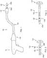
FIGS. 10-12 , another embodiment of an assembly for protecting theelongate body 104 of theadapter assembly 100 and theloading unit 110 that is secured to theelongate body 104, and for minimizing damage to tissue of a patient during introduction of theadapter assembly 100 within the patient, is shown generally asprotective assembly 500. Theprotective assembly 500 includes asleeve member 502, and acap member 504 secured to a distal end of thesleeve member 502. Thesleeve member 502 is configured to be received about theelongate body 104 ofadapter assembly 100. Thecap member 504 is configured to be releasably received about theloading unit 110 secured to the distal end of theelongate body 104 of theadapter assembly 100. - The
sleeve member 502 of theprotective assembly 500 is substantially similar tosleeve member 402 of theprotective assembly 400 described above, and includes an elongateflexible body 506. As shown, thecap member 504 includes a substantially conical shape and may be transparent or translucent. Thecap member 504 is formed of flexible plastic or other suitable material, and is divided into multiple leaves orsections 504a. For example, and as shown, thecap member 504 includes two leaves (FIG. 11A ), three leaves (FIG. 11B ), four leaves (FIG. 11C ), or five leaves (FIG. 11D ). Theleaves 504a may be connected by afrangible connection 504b, e.g., weakened plastic bridges, which are configured to break during retraction of thesleeve member 502 relative to theelongate body 104 of theadapter assembly 100. The greater number ofleaves 504a, the less room thecap member 504 will occupy radially as theprotective assembly 500 is removed from about theelongate body 104 of theadapter assembly 100. - The elongate
flexible body 506 of thesleeve member 502 may be constructed of a more flexible material than thecap member 504. Thecap member 504 may be made more rigid by increasing the wall thickness of theleaves 504a or by using a stiffer material to construct thecap member 504. - As shown in
FIG. 12 , removal of theprotective assembly 500 from about theelongate body 104 of theadapter assembly 100 requires pullinghandle members 508 proximally and radially outward relative to theelongate body 104, as indicated by arrows "A", to cause tearing of thesleeve member 502 along a tear-line 512 and to cause separation of theleaves 504a of thecap member 504. As thesleeve member 502 is separated along the tear-line 512 and thesleeve member 502 is retracted proximally relative to theelongate body 104, theleaves 504a of thecap member 504 separate to permit passage of theloading unit 110 therethrough. Once completely removed from about theelongate body 104 of theadapter assembly 100, the clinician may dispose of theprotective assembly 500, and theadapter assembly 100 may be used in a traditional manner. - Turning to
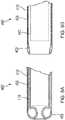
FIGS. 13-15 , another embodiment of an assembly for protecting theelongate body 104 of theadapter assembly 100 and an attachedloading unit 110, is shown generally asprotective assembly 600. Theprotective assembly 600 includes asleeve member 602, and acap member 604 secured to a distal end of thesleeve member 602. Theprotective assembly 600 further includes acamera assembly 606 supported within thecap member 604. Thecamera assembly 606 may connect with a monitoring unit (not shown) wirelessly, or through a wire "W" (FIG. 15 ) extending along the length of thesleeve member 602. - The
cap member 604 includes a plurality ofleaves 604a. Thecamera assembly 606 is supported on a distal end of one of theleaves 604a. Thecamera assembly 606 may be removable to permit reuse. Thecamera assembly 606 permits viewing as theelongate body 104 of theadapter assembly 100 is introduced into a patient. Thecamera assembly 606 may include charge-coupled device (CCD) cameras, or other suitable cameras. - With reference now to
FIGS. 16 and 17 , an assembly for protecting theelongate body 104 of theadapter assembly 100 and aloading unit 110 attached to theelongate body 104, is shown generally asprotective assembly 700. Theprotective assembly 700 is substantially similar toprotective assemblies protective assembly 700 includes asleeve member 702, acap member 704 integrally formed with or secured to a distal end of thesleeve member 702, and asteering assembly 706 supported on and extending through thesleeve member 702. - The
steering assembly 706 includes asteering ring 708, and a plurality ofsteering cables 710 extending from thesteering ring 708 and through thesleeve member 702. Thesteering cables 710 are each received through alumen 705 of thesleeve member 702. As shown, theprotective assembly 700 includes four (4)steering cables 710. However, it is envisioned that theprotective assembly 700 may have more or less than four (4)steering cables 710. - During a surgical procedure, after the
protective assembly 700 is received about theelongate body 104 of theadapter assembly 100, thesteering ring 708 may be used to guide theelongate body 104 of theadapter assembly 100 within a patient. More particularly, rotation of thesteering ring 708 of theprotective assembly 700 about a longitudinal axis of theadapter assembly 100, as indicated by arrows "B" inFIG. 16 , causes corresponding movement of thesleeve member 702 of theprotective assembly 700 which moves theelongate body 104 of theadapter assembly 100. As theadapter assembly 100 is being introduced into a patient, rotation of thesteering ring 708 relative to theadapter assembly 100 facilitates continued movement of theadapter assembly 100 to the desired position. - With reference now to
FIG. 18 , an assembly for protecting theloading unit 110 secured to the distal end of theelongate body 104 of theadapter assembly 100 is shown generally asprotective assembly 800. Theprotective assembly 800 includes an inflatable member 802 configured for operable engagement of theloading unit 110, and aninsufflation port 804 for effecting insufflation of the inflatable member 802. Theinsufflation port 804 may include a luer connector, or other suitable connection means, and is in fluid communication with the inflatable member 802 through aninflation tube 804a. Theprotective assembly 800 may further include a syringe, canister, bellow, or other suitable means for inflating the inflatable member 802. - The inflatable member 802 of the protective assembly has a first substantially
spherical portion 802a, and a second substantiallyspherical portion 802b extending from the first substantiallyspherical portion 802a. The first substantiallyspherical portion 802a being greater in size or diameter than the second substantiallyspherical portion 802b when the inflatable member 802 is in an inflated condition. As shown inFIG. 18 , when the inflatable member 802 is in the inflated condition, the second substantiallyspherical portion 802b is securely received within acylindrical cavity 111 of theloading unit 110 which is secured to the distal end of theelongate body 104 of theadapter assembly 100. When the second substantiallyspherical portion 802b of the inflatable member 802 is received within thecylindrical cavity 111 of theloading unit 110, the first substantiallyspherical portion 802a covers a distal end of theloading unit 110. In this manner, the inflatable member 802 prevents contact of the distal end of theloading unit 110 with tissue as theadapter assembly 100 and the attachedprotective assembly 800 is introduced within a patient. - It is envisioned that the first substantially
spherical portion 802a of the inflatable member 802 may be configured to match the contour of theloading unit 110. In this manner, the inflatable member 802 more closely aligns with theloading unit 110. - With reference now to
FIGS. 19-21 , an embodiment of a loading unit according to the present disclosure is shown generally asloading unit 910. Theloading unit 910 is configured for operable connection to the distal end of the elongate body 104 (FIG. 1 ) of the adapter assembly 100 (FIG. 1 ). Briefly, theloading unit 910 includes ashell 912 and acartridge assembly 914 mounted on a distal end of theshell 912. Theshell 912 defines alumen 915 extending therethrough for providing a pathway through thecartridge assembly 914. Thelumen 915 may be used to, for example, provide irrigation fluids "I" (FIG. 21 ) to the tissue being stapled "T". In addition, thelumen 915 may be used to receive, for example, guide wires, scopes "S" (FIG. 20 ), or other suitable instruments during a stapling procedure. Aconnector sleeve 916 may be received on a proximal end of thelumen 915 to facilitate receipt of a fluid and/or instrument into and through the lumen. - It is envisioned that the embodiments of the present disclosure may be modified for use with various electromechanical surgical instruments and/or electrosurgical instruments. It is further envisioned that these instruments may, for example, be configured to be detachably coupleable and controllable by a robotic surgical system.
- With reference now to
FIG. 22 , an exemplary robotic surgical system is shown generally as robotic surgical system 1 and, may include a plurality of surgical robotic arms, e.g., surgicalrobotic arms 2, 3, each having an instrument drive unit, e.g.,instrument drive unit surgical stapler console 4, coupled with the control device 5. As shown, the robotic surgical system 1 is configured for use on a patient "P" lying on a surgical table "ST" to be treated in a minimally invasive manner by means of thesurgical stapler - For a detailed description of the construction and operation of an examplary robotic surgical system, reference may be made to
U.S. Patent Application Publication No. 2012/0116416 . - Persons skilled in the art will understand that the devices and methods specifically described herein and illustrated in the accompanying drawings are non-limiting exemplary embodiments. It is envisioned that the elements and features illustrated or described in connection with one exemplary embodiment may be combined with the elements and features of another without departing from the scope of the present disclosure. As well, one skilled in the art will appreciate further features and advantages of the disclosure based on the above-described embodiments. Accordingly, the disclosure is not to be limited by what has been particularly shown and described, except as indicated by the appended claims.
Claims (3)
- An adapter assembly (100, 200) for connecting a handle assembly (10) with a loading unit (110, 210), the adapter assembly comprising:a housing (102, 202);an elongate body (104, 204) extending from the housing;a trocar assembly supported within the elongate body and including a trocar member (106, 206), wherein the trocar member extends from the elongate body, wherein the trocar member is magnetized; andan anvil assembly (120);characterised in that the anvil assembly includes a removable tip (130), the removable tip being magnetized to complement the trocar member such that the removable tip is magnetically attracted to the trocar member, wherein the removable tip includes a proximal portion (130a) configured for piercing tissue and a distal portion (130b) configured for operable connection to the proximal end (126a) of a center rod (126) of the anvil assembly,wherein the proximal portion (130a) of the removable tip (130) includes a first magnetic polarity, and the distal portion (130b) of the removable tip (130) includes a second magnetic polarity.
- The adapter assembly (100, 200) of any preceding claim, wherein the trocar assembly includes an electromagnet (240) received about the trocar member (106, 206) for selectively magnetizing the trocar member.
- The adapter assembly (100, 200) according to any preceding claim further including a light source.
Priority Applications (1)
| Application Number | Priority Date | Filing Date | Title |
|---|---|---|---|
| EP22174511.0AEP4074266A1 (en) | 2016-05-10 | 2017-05-09 | Insertion instrument, adapter assemblies and protector assemblies for a flexible circular stapler |
Applications Claiming Priority (2)
| Application Number | Priority Date | Filing Date | Title |
|---|---|---|---|
| US201662334145P | 2016-05-10 | 2016-05-10 | |
| US15/583,594US10595871B2 (en) | 2016-05-10 | 2017-05-01 | Insertion instrument, adapter assemblies and protector assemblies for a flexible circular stapler |
Related Child Applications (2)
| Application Number | Title | Priority Date | Filing Date |
|---|---|---|---|
| EP22174511.0ADivisionEP4074266A1 (en) | 2016-05-10 | 2017-05-09 | Insertion instrument, adapter assemblies and protector assemblies for a flexible circular stapler |
| EP22174511.0ADivision-IntoEP4074266A1 (en) | 2016-05-10 | 2017-05-09 | Insertion instrument, adapter assemblies and protector assemblies for a flexible circular stapler |
Publications (3)
| Publication Number | Publication Date |
|---|---|
| EP3243449A2 EP3243449A2 (en) | 2017-11-15 |
| EP3243449A3 EP3243449A3 (en) | 2018-01-10 |
| EP3243449B1true EP3243449B1 (en) | 2022-06-29 |
Family
ID=58692436
Family Applications (2)
| Application Number | Title | Priority Date | Filing Date |
|---|---|---|---|
| EP22174511.0AWithdrawnEP4074266A1 (en) | 2016-05-10 | 2017-05-09 | Insertion instrument, adapter assemblies and protector assemblies for a flexible circular stapler |
| EP17170075.0AActiveEP3243449B1 (en) | 2016-05-10 | 2017-05-09 | Adapter assemblies for a flexible circular stapler |
Family Applications Before (1)
| Application Number | Title | Priority Date | Filing Date |
|---|---|---|---|
| EP22174511.0AWithdrawnEP4074266A1 (en) | 2016-05-10 | 2017-05-09 | Insertion instrument, adapter assemblies and protector assemblies for a flexible circular stapler |
Country Status (3)
| Country | Link |
|---|---|
| US (3) | US10595871B2 (en) |
| EP (2) | EP4074266A1 (en) |
| CN (2) | CN107361807B (en) |
Families Citing this family (35)
| Publication number | Priority date | Publication date | Assignee | Title |
|---|---|---|---|---|
| US10561424B2 (en)* | 2011-05-20 | 2020-02-18 | Covidien Lp | Methods of inserting a circular stapling apparatus into a body lumen |
| US10595871B2 (en) | 2016-05-10 | 2020-03-24 | Covidien Lp | Insertion instrument, adapter assemblies and protector assemblies for a flexible circular stapler |
| JP7278717B2 (en)* | 2017-05-30 | 2023-05-22 | コヴィディエン リミテッド パートナーシップ | A method for inserting a circular stapling device into a body lumen |
| US10595873B2 (en)* | 2018-04-19 | 2020-03-24 | Franklin Institute of Innovation, LLC | Surgical staplers and related methods |
| US20210219978A1 (en)* | 2018-05-10 | 2021-07-22 | Franklin Institute of Innovation, LLC | Surgical staplers and related methods |
| US11564691B2 (en) | 2018-08-24 | 2023-01-31 | Covidien Lp | Powered circular stapling device |
| CA3139541A1 (en) | 2019-05-31 | 2020-12-03 | Covidien Lp | Circular stapling device |
| US11730481B2 (en) | 2020-01-06 | 2023-08-22 | Covidien Lp | Assemblies for retaining a trocar assembly |
| US11911038B2 (en) | 2020-01-13 | 2024-02-27 | Covidien Lp | Cut optimization for excessive tissue conditions |
| US11523828B2 (en) | 2020-01-28 | 2022-12-13 | Covidien Lp | Sealed reload assembly for stapling device |
| IT202000002551A1 (en)* | 2020-02-10 | 2021-08-10 | Medical Microinstruments Spa | TIP PROTECTOR DEVICE FOR A SURGICAL INSTRUMENT, ASSEMBLY AND METHOD |
| US11622767B2 (en) | 2020-02-19 | 2023-04-11 | Covidien Lp | Sealed trocar assembly for stapling device |
| US11779343B2 (en) | 2020-02-26 | 2023-10-10 | Covidien Lp | Staple reload assembly with releasable knife |
| US11653925B2 (en) | 2020-05-21 | 2023-05-23 | Covidien Lp | Tissue relaxation monitoring for optimized tissue stapling |
| US11547405B2 (en) | 2020-05-22 | 2023-01-10 | Covidien Lp | Surgical stapling device |
| US20220015856A1 (en)* | 2020-07-14 | 2022-01-20 | Covidien Lp | Surgical stapler with illumination |
| US11553921B2 (en) | 2020-07-15 | 2023-01-17 | Covidien Lp | Surgical stapling device with flexible shaft |
| US12076505B2 (en) | 2020-08-06 | 2024-09-03 | Canon U.S.A., Inc. | Magnetic connector for steerable medical device |
| US11627966B2 (en) | 2020-08-26 | 2023-04-18 | Covidien Lp | Surgical stapling device |
| US11801054B2 (en) | 2020-09-22 | 2023-10-31 | Covidien Lp | Surgical stapler with oval tool assembly |
| US11712509B2 (en) | 2020-10-02 | 2023-08-01 | Covidien Lp | Seal assembly for circular stapling instrument |
| US11627967B2 (en) | 2020-11-23 | 2023-04-18 | Covidien Lp | Trans-anastomotic insertion device |
| EP4262580B1 (en) | 2020-12-15 | 2025-10-08 | Covidien LP | Surgical stapling device rotatable camming element |
| US11877750B2 (en) | 2021-01-21 | 2024-01-23 | Covidien Lp | Surgical stapler with powered and manual functions |
| US11986187B2 (en) | 2021-01-29 | 2024-05-21 | Covidien Lp | Circular stapling device with integrated visualization device |
| US11786241B2 (en) | 2021-02-16 | 2023-10-17 | Covidien Lp | Surgical stapling device including a hydraulic staple formation mechanism |
| US11553920B2 (en) | 2021-05-03 | 2023-01-17 | Covidien Lp | Trocar retainer assembly for surgical stapler |
| US11490894B1 (en) | 2021-05-12 | 2022-11-08 | Covidien Lp | Surgical device with grease filter |
| US11642131B2 (en) | 2021-05-17 | 2023-05-09 | Covidien Lp | Devices and methods for shortening a rectal stump during a lower anterior resection procedure |
| CN117715596A (en) | 2021-05-24 | 2024-03-15 | 柯惠有限合伙公司 | Anvil and delivery system components with automatic holding suture release |
| US11612400B2 (en) | 2021-05-24 | 2023-03-28 | Covidien Lp | Trocar assembly with bearing assembly for load sharing |
| US11737759B2 (en) | 2021-08-05 | 2023-08-29 | Covidien Lp | Surgical stapling device accommodating prolapsed tissue |
| US11883028B2 (en) | 2021-09-08 | 2024-01-30 | Covidien Lp | Systems and methods for post-operative anastomotic leak detection |
| US11717299B2 (en) | 2021-10-12 | 2023-08-08 | Covidien Lp | Surgical stapling device with probiotics |
| US12213674B2 (en) | 2021-12-08 | 2025-02-04 | Covidien Lp | Determination of premature staple ejection |
Citations (2)
| Publication number | Priority date | Publication date | Assignee | Title |
|---|---|---|---|---|
| US5350104A (en)* | 1991-08-23 | 1994-09-27 | Ethicon, Inc. | Sealing means for endoscopic surgical anastomosis stapling instrument |
| EP3108825A2 (en)* | 2015-06-26 | 2016-12-28 | Ethicon Endo-Surgery, LLC | Anvil stabilization features for surgical stapler |
Family Cites Families (366)
| Publication number | Priority date | Publication date | Assignee | Title |
|---|---|---|---|---|
| CA908529A (en) | 1972-08-29 | V. Astafiev Georgy | Surgical instrument for suturing hollow organs in infants | |
| DE1057729B (en) | 1954-03-29 | 1959-05-21 | Lameris Instr N V | Surgical device for connecting two parts of the intestine |
| GB787043A (en) | 1954-09-15 | 1957-11-27 | Sylvania Electric Prod | Method for production of silicon |
| CA736256A (en) | 1962-08-27 | 1966-06-14 | S. Kasoolin Viacheslav | Instrument for suturing esophagus to intestine or stomach |
| FR1461464A (en) | 1965-08-20 | 1966-02-25 | Niiex Khirurgicheskoi Apparatu | Surgical device for suturing organs |
| CH470170A (en) | 1968-02-02 | 1969-03-31 | Vnii Khirurgicheskoi Apparatur | Device for applying round anastomoses |
| US3638652A (en) | 1970-06-01 | 1972-02-01 | James L Kelley | Surgical instrument for intraluminal anastomosis |
| US3771526A (en) | 1972-02-07 | 1973-11-13 | P Rudie | Anastomosis clamp |
| US4304236A (en) | 1977-05-26 | 1981-12-08 | United States Surgical Corporation | Stapling instrument having an anvil-carrying part of particular geometric shape |
| US4603693A (en) | 1977-05-26 | 1986-08-05 | United States Surgical Corporation | Instrument for circular surgical stapling of hollow body organs and disposable cartridge therefor |
| US4573468A (en) | 1977-05-26 | 1986-03-04 | United States Surgical Corporation | Hollow body organ stapling instrument and disposable cartridge employing relief vents |
| NL7711347A (en) | 1977-10-17 | 1979-04-19 | Carl Robert Erik Daantje | Stapling instrument for joining intestine ends - has head coupling rod in two parts screwing together with hand grip |
| US4207898A (en) | 1978-03-27 | 1980-06-17 | Senco Products, Inc. | Intralumenal anastomosis surgical stapling instrument |
| US4198982A (en) | 1978-03-31 | 1980-04-22 | Memorial Hospital For Cancer And Allied Diseases | Surgical stapling instrument and method |
| DE2947107A1 (en) | 1978-12-07 | 1980-06-26 | United States Surgical Corp | ACCURATELY ALIGNED CARTRIDGE AND INSTRUMENT FOR CLAMPING ANASTOMOSES |
| SU1088712A1 (en) | 1979-11-14 | 1984-04-30 | Всесоюзный научно-исследовательский и испытательный институт медицинской техники | Apparatus for circular suture of blood vessels |
| AU534210B2 (en) | 1980-02-05 | 1984-01-12 | United States Surgical Corporation | Surgical staples |
| US4319576A (en) | 1980-02-26 | 1982-03-16 | Senco Products, Inc. | Intralumenal anastomosis surgical stapling instrument |
| US4289133A (en) | 1980-02-28 | 1981-09-15 | Senco Products, Inc. | Cut-through backup washer for the scalpel of an intraluminal surgical stapling instrument |
| US4606343A (en) | 1980-08-18 | 1986-08-19 | United States Surgical Corporation | Self-powered surgical fastening instrument |
| US4351466A (en) | 1980-10-16 | 1982-09-28 | United States Surgical Corporation | Disposable instrument for surgical fastening |
| US4379457A (en) | 1981-02-17 | 1983-04-12 | United States Surgical Corporation | Indicator for surgical stapler |
| US4476863A (en) | 1981-03-09 | 1984-10-16 | Kanshin Nikolai N | Surgical instrument for establishing circular coloanastomoses |
| US4632290A (en) | 1981-08-17 | 1986-12-30 | United States Surgical Corporation | Surgical stapler apparatus |
| US4576167A (en) | 1981-09-03 | 1986-03-18 | United States Surgical Corporation | Surgical stapler apparatus with curved shaft |
| SU1114405A1 (en) | 1982-02-23 | 1984-09-23 | Всесоюзный научно-исследовательский и испытательный институт медицинской техники | Surgical suturing apparatus for placing compression anastomoses on the organs of digestive tract |
| US4473077A (en) | 1982-05-28 | 1984-09-25 | United States Surgical Corporation | Surgical stapler apparatus with flexible shaft |
| US4485817A (en) | 1982-05-28 | 1984-12-04 | United States Surgical Corporation | Surgical stapler apparatus with flexible shaft |
| US4488523A (en) | 1982-09-24 | 1984-12-18 | United States Surgical Corporation | Flexible, hydraulically actuated device for applying surgical fasteners |
| DE3301713A1 (en) | 1983-01-20 | 1984-07-26 | Horst Dr. 3004 Isernhagen Ziegler | Surgical clip suture apparatus for producing circular joins |
| US4592354A (en) | 1983-10-11 | 1986-06-03 | Senmed, Inc. | Tissue retention spool for intraluminal anastomotic surgical stapling instrument and methods |
| US4505414A (en) | 1983-10-12 | 1985-03-19 | Filipi Charles J | Expandable anvil surgical stapler |
| US4550870A (en) | 1983-10-13 | 1985-11-05 | Alchemia Ltd. Partnership | Stapling device |
| IT1173284B (en) | 1984-02-16 | 1987-06-18 | Riccardo Rosati | CIRCULAR MECHANICAL STAPLING MACHINE |
| US4667673A (en) | 1984-03-12 | 1987-05-26 | American Cyanamid Company | Anastomotic device applicator and method |
| US4754909A (en) | 1984-08-09 | 1988-07-05 | Barker John M | Flexible stapler |
| US4671445A (en) | 1984-08-09 | 1987-06-09 | Baxter Travenol Laboratories, Inc. | Flexible surgical stapler assembly |
| AU582625B2 (en) | 1985-01-28 | 1989-04-06 | Ethicon Inc. | Tissue gripper for use with intraluminal stapling device |
| US4703887A (en) | 1985-01-28 | 1987-11-03 | Ethicon, Inc. | Collapsible purse string aid for use with intraluminal stapling device |
| US4665917A (en) | 1985-01-28 | 1987-05-19 | Ethicon, Inc. | Tissue gripper for use with intraluminal stapling device |
| JPS635697Y2 (en) | 1985-04-04 | 1988-02-17 | ||
| JPS62140776A (en) | 1985-12-16 | 1987-06-24 | 海老原 代師行 | Stapler |
| US4700703A (en) | 1986-03-27 | 1987-10-20 | Semion Resnick | Cartridge assembly for a surgical stapling instrument |
| US4903697A (en) | 1986-03-27 | 1990-02-27 | Semion Resnick | Cartridge assembly for a surgical stapling instrument |
| US4817847A (en) | 1986-04-21 | 1989-04-04 | Finanzaktiengesellschaft Globe Control | Instrument and a procedure for performing an anastomosis |
| US4917114A (en) | 1986-10-17 | 1990-04-17 | United States Surgical Corporation | Surgical fastener and surgical stapling apparatus |
| US4752024A (en) | 1986-10-17 | 1988-06-21 | Green David T | Surgical fastener and surgical stapling apparatus |
| US4776506A (en) | 1986-11-13 | 1988-10-11 | United States Surgical Corporation | Surgical stapler apparatus |
| US4873977A (en) | 1987-02-11 | 1989-10-17 | Odis L. Avant | Stapling method and apparatus for vesicle-urethral re-anastomosis following retropubic prostatectomy and other tubular anastomosis |
| US5119983A (en) | 1987-05-26 | 1992-06-09 | United States Surgical Corporation | Surgical stapler apparatus |
| US5158222A (en) | 1987-05-26 | 1992-10-27 | United States Surgical Corp. | Surgical stapler apparatus |
| US5285944A (en) | 1987-05-26 | 1994-02-15 | United States Surgical Corporation | Surgical stapler apparatus |
| SU1616624A1 (en) | 1987-07-14 | 1990-12-30 | Предприятие П/Я А-3697 | Surgical suturing apparatus |
| SU1509052A1 (en) | 1988-01-18 | 1989-09-23 | С. А. Попов | Surgical suturing apparatus |
| US4907591A (en) | 1988-03-29 | 1990-03-13 | Pfizer Hospital Products Group, Inc. | Surgical instrument for establishing compression anastomosis |
| US5005749A (en) | 1988-07-01 | 1991-04-09 | United States Surgical Corp. | Anastomosis surgical stapling instrument |
| US5193731A (en) | 1988-07-01 | 1993-03-16 | United States Surgical Corporation | Anastomosis surgical stapling instrument |
| ES2011110A6 (en) | 1988-09-02 | 1989-12-16 | Lopez Hervas Pedro | Hydraulic device with flexible body for surgical anastomosts |
| US5197648A (en) | 1988-11-29 | 1993-03-30 | Gingold Bruce S | Surgical stapling apparatus |
| AU4742190A (en) | 1988-11-29 | 1990-06-26 | Bruce S. Gingold | Surgical stapling apparatus |
| US4893662A (en) | 1988-12-06 | 1990-01-16 | Vito Gervasi | Cutting tool |
| CH677728A5 (en) | 1989-10-17 | 1991-06-28 | Bieffe Medital Sa | |
| US5366462A (en) | 1990-08-28 | 1994-11-22 | Robert L. Kaster | Method of side-to-end vascular anastomotic stapling |
| US5047039A (en) | 1990-09-14 | 1991-09-10 | Odis Lynn Avant | Method and apparatus for effecting dorsal vein ligation and tubular anastomosis and laparoscopic prostatectomy |
| US5253793A (en) | 1990-09-17 | 1993-10-19 | United States Surgical Corporation | Apparatus for applying two-part surgical fasteners |
| US5104025A (en) | 1990-09-28 | 1992-04-14 | Ethicon, Inc. | Intraluminal anastomotic surgical stapler with detached anvil |
| US5042707A (en) | 1990-10-16 | 1991-08-27 | Taheri Syde A | Intravascular stapler, and method of operating same |
| CA2055943C (en) | 1990-12-06 | 2003-09-23 | Daniel P. Rodak | Surgical fastening apparatus with locking mechanism |
| US5122156A (en) | 1990-12-14 | 1992-06-16 | United States Surgical Corporation | Apparatus for securement and attachment of body organs |
| US5222963A (en) | 1991-01-17 | 1993-06-29 | Ethicon, Inc. | Pull-through circular anastomosic intraluminal stapler with absorbable fastener means |
| ATE135182T1 (en) | 1991-03-29 | 1996-03-15 | Perouse Implant Lab | SURGICAL STAPLE SEWING DEVICE |
| US5221036A (en) | 1991-06-11 | 1993-06-22 | Haruo Takase | Surgical stapler |
| GR920100358A (en) | 1991-08-23 | 1993-06-07 | Ethicon Inc | Surgical anastomosis stapling instrument. |
| US5333773A (en) | 1991-08-23 | 1994-08-02 | Ethicon, Inc. | Sealing means for endoscopic surgical anastomosis stapling instrument |
| US5474223A (en) | 1991-10-18 | 1995-12-12 | United States Surgical Corporation | Surgical fastener applying apparatus |
| US5443198A (en) | 1991-10-18 | 1995-08-22 | United States Surgical Corporation | Surgical fastener applying apparatus |
| US5197649A (en) | 1991-10-29 | 1993-03-30 | The Trustees Of Columbia University In The City Of New York | Gastrointestinal endoscoptic stapler |
| US5433721A (en) | 1992-01-17 | 1995-07-18 | Ethicon, Inc. | Endoscopic instrument having a torsionally stiff drive shaft for applying fasteners to tissue |
| US5188638A (en) | 1992-02-06 | 1993-02-23 | Tzakis Andreas G | Apparatus and method for preforming anastomosis fastener securement of hollow organs |
| US5271543A (en) | 1992-02-07 | 1993-12-21 | Ethicon, Inc. | Surgical anastomosis stapling instrument with flexible support shaft and anvil adjusting mechanism |
| US5348259A (en) | 1992-02-10 | 1994-09-20 | Massachusetts Institute Of Technology | Flexible, articulable column |
| US5282810A (en) | 1992-04-08 | 1994-02-01 | American Cyanamid Company | Surgical anastomosis device |
| US5425738A (en) | 1992-04-08 | 1995-06-20 | American Cyanamid Company | Endoscopic anastomosis ring insertion device and method of use thereof |
| US5355897A (en) | 1992-04-16 | 1994-10-18 | Ethicon, Inc. | Method of performing a pyloroplasty/pylorectomy using a stapler having a shield |
| US5314435A (en) | 1992-05-19 | 1994-05-24 | United States Surgical Corporation | Anvil delivery system |
| US5344059A (en) | 1992-05-19 | 1994-09-06 | United States Surgical Corporation | Surgical apparatus and anvil delivery system therefor |
| US5658300A (en) | 1992-06-04 | 1997-08-19 | Olympus Optical Co., Ltd. | Tissue fixing surgical instrument, tissue-fixing device, and method of fixing tissues |
| JPH0647050A (en) | 1992-06-04 | 1994-02-22 | Olympus Optical Co Ltd | Tissue suture and ligature device |
| US5360154A (en) | 1992-07-17 | 1994-11-01 | United States Surgical Corporation | Apparatus for creating partial anastomoses |
| US5330486A (en)* | 1992-07-29 | 1994-07-19 | Wilk Peter J | Laparoscopic or endoscopic anastomosis technique and associated instruments |
| US5261920A (en) | 1992-08-21 | 1993-11-16 | Ethicon, Inc. | Anvil bushing for circular stapler |
| US5368215A (en) | 1992-09-08 | 1994-11-29 | United States Surgical Corporation | Surgical apparatus and detachable anvil rod therefor |
| US5309927A (en) | 1992-10-22 | 1994-05-10 | Ethicon, Inc. | Circular stapler tissue retention spring method |
| US5314436A (en) | 1992-10-30 | 1994-05-24 | Wilk Peter J | Method and apparatus for performing end-to-end anastomoses |
| US5404870A (en) | 1993-05-28 | 1995-04-11 | Ethicon, Inc. | Method of using a transanal inserter |
| US5503320A (en) | 1993-08-19 | 1996-04-02 | United States Surgical Corporation | Surgical apparatus with indicator |
| US5437684A (en) | 1993-10-01 | 1995-08-01 | United States Surgical Corporation | Circular anastomosis device |
| US5522534A (en) | 1993-10-01 | 1996-06-04 | United States Surgical Corporation | Anvil for surgical stapler |
| US5454825A (en) | 1993-10-01 | 1995-10-03 | United States Surgical Corporation | Circular anastomosis device with seal |
| US5447514A (en) | 1993-10-01 | 1995-09-05 | United States Surgical Corporation | Circular anastomosis device |
| CA2132917C (en) | 1993-10-07 | 2004-12-14 | John Charles Robertson | Circular anastomosis device |
| US5503635A (en) | 1993-11-12 | 1996-04-02 | United States Surgical Corporation | Apparatus and method for performing compressional anastomoses |
| DE4407668A1 (en) | 1994-03-09 | 1995-09-14 | Ferdinand Dr Koeckerling | Surgical anastomotic ring setting device |
| US5464415A (en) | 1994-03-15 | 1995-11-07 | Chen; Te-Chuan | Sutureless intestinal anastomosis gun |
| US5860581A (en) | 1994-03-24 | 1999-01-19 | United States Surgical Corporation | Anvil for circular stapler |
| US5715987A (en) | 1994-04-05 | 1998-02-10 | Tracor Incorporated | Constant width, adjustable grip, staple apparatus and method |
| CA2147800C (en) | 1994-05-26 | 2006-07-11 | John Charles Robertson | Circular anastomosis device |
| US5732872A (en) | 1994-06-17 | 1998-03-31 | Heartport, Inc. | Surgical stapling instrument |
| WO1995035065A1 (en) | 1994-06-17 | 1995-12-28 | Heartport, Inc. | Surgical stapling instrument and method thereof |
| US5881943A (en) | 1994-06-17 | 1999-03-16 | Heartport, Inc. | Surgical anastomosis apparatus and method thereof |
| CA2146508C (en) | 1994-08-25 | 2006-11-14 | Robert H. Schnut | Anvil for circular stapler |
| US5685474A (en) | 1994-10-04 | 1997-11-11 | United States Surgical Corporation | Tactile indicator for surgical instrument |
| US5868760A (en) | 1994-12-07 | 1999-02-09 | Mcguckin, Jr.; James F. | Method and apparatus for endolumenally resectioning tissue |
| US7235089B1 (en) | 1994-12-07 | 2007-06-26 | Boston Scientific Corporation | Surgical apparatus and method |
| US5720755A (en) | 1995-01-18 | 1998-02-24 | Dakov; Pepi | Tubular suturing device and methods of use |
| US5904697A (en) | 1995-02-24 | 1999-05-18 | Heartport, Inc. | Devices and methods for performing a vascular anastomosis |
| DE19509115C2 (en) | 1995-03-16 | 1997-11-27 | Deutsche Forsch Luft Raumfahrt | Surgical device for preparing an anastomosis using minimally invasive surgical techniques |
| US5769841A (en) | 1995-06-13 | 1998-06-23 | Electroscope, Inc. | Electrosurgical apparatus for laparoscopic and like procedures |
| US5641111A (en) | 1995-06-28 | 1997-06-24 | Ethicon Endo-Surgery, Inc. | Surgical stapling instrument with anvil cutting guide |
| US5749896A (en) | 1995-07-18 | 1998-05-12 | Cook; Melvin S. | Staple overlap |
| US5839639A (en) | 1995-08-17 | 1998-11-24 | Lasersurge, Inc. | Collapsible anvil assembly and applicator instrument |
| US5814055A (en) | 1995-09-19 | 1998-09-29 | Ethicon Endo-Surgery, Inc. | Surgical clamping mechanism |
| AU701033B2 (en) | 1995-10-31 | 1999-01-21 | Bernafon Ag | Method and anastomotic instrument for use when performing an end-to-side anastomosis |
| US5836503A (en) | 1996-04-22 | 1998-11-17 | United States Surgical Corporation | Insertion device for surgical apparatus |
| US6050472A (en) | 1996-04-26 | 2000-04-18 | Olympus Optical Co., Ltd. | Surgical anastomosis stapler |
| US6119913A (en) | 1996-06-14 | 2000-09-19 | Boston Scientific Corporation | Endoscopic stapler |
| US6024748A (en) | 1996-07-23 | 2000-02-15 | United States Surgical Corporation | Singleshot anastomosis instrument with detachable loading unit and method |
| US20020019642A1 (en) | 1996-07-23 | 2002-02-14 | Keith Milliman | Anastomosis instrument and method for performing same |
| US5833698A (en) | 1996-07-23 | 1998-11-10 | United States Surgical Corporation | Anastomosis instrument and method |
| US6440146B2 (en) | 1996-07-23 | 2002-08-27 | United States Surgical Corporation | Anastomosis instrument and method |
| US5855312A (en) | 1996-07-25 | 1999-01-05 | Toledano; Haviv | Flexible annular stapler for closed surgery of hollow organs |
| US5853395A (en) | 1997-02-18 | 1998-12-29 | Dexterity, Inc. | Extracorporeal pneumoperitoneum enclosure and method of use |
| US6338737B1 (en) | 1997-07-17 | 2002-01-15 | Haviv Toledano | Flexible annular stapler for closed surgery of hollow organs |
| US5865361A (en) | 1997-09-23 | 1999-02-02 | United States Surgical Corporation | Surgical stapling apparatus |
| US6117148A (en) | 1997-10-17 | 2000-09-12 | Ravo; Biagio | Intraluminal anastomotic device |
| US5951576A (en) | 1998-03-02 | 1999-09-14 | Wakabayashi; Akio | End-to-side vascular anastomosing stapling device |
| US6279809B1 (en) | 1998-03-10 | 2001-08-28 | Enrico Nicolo | Circular stapler for side to end, side to side and end to side anastomosis |
| US6517566B1 (en) | 1998-05-11 | 2003-02-11 | Surgical Connections, Inc. | Devices and methods for treating e.g. urinary stress incontinence |
| AU751697B2 (en) | 1998-05-11 | 2002-08-22 | Surgical Connections, Inc. | Devices and methods for treating e.g. urinary stress incontinence |
| US6601749B2 (en) | 1998-06-19 | 2003-08-05 | Scimed Life Systems, Inc. | Multi fire full thickness resectioning device |
| US6629630B2 (en) | 1998-06-19 | 2003-10-07 | Scimed Life Systems, Inc. | Non-circular resection device and endoscope |
| US6478210B2 (en) | 2000-10-25 | 2002-11-12 | Scimed Life Systems, Inc. | Method and device for full thickness resectioning of an organ |
| US6126058A (en) | 1998-06-19 | 2000-10-03 | Scimed Life Systems, Inc. | Method and device for full thickness resectioning of an organ |
| US6585144B2 (en) | 1998-06-19 | 2003-07-01 | Acimed Life Systems, Inc. | Integrated surgical staple retainer for a full thickness resectioning device |
| DE19837258A1 (en) | 1998-08-17 | 2000-03-02 | Deutsch Zentr Luft & Raumfahrt | Device for operating a surgical instrument for anastomosis of hollow organs |
| DE19836950B4 (en) | 1998-08-17 | 2004-09-02 | Deutsches Zentrum für Luft- und Raumfahrt e.V. | Surgical instrument in the form of a suturing device |
| US6203553B1 (en) | 1999-09-08 | 2001-03-20 | United States Surgical | Stapling apparatus and method for heart valve replacement |
| US6102271A (en) | 1998-11-23 | 2000-08-15 | Ethicon Endo-Surgery, Inc. | Circular stapler for hemorrhoidal surgery |
| US6142933A (en) | 1998-11-23 | 2000-11-07 | Ethicon Endo-Surgery, Inc. | Anoscope for hemorrhoidal surgery |
| US6083241A (en) | 1998-11-23 | 2000-07-04 | Ethicon Endo-Surgery, Inc. | Method of use of a circular stapler for hemorrhoidal procedure |
| US6743244B2 (en) | 1999-04-16 | 2004-06-01 | Integrated Vascular Interventional Technologies, L.C. | Soft anvil apparatus for cutting anastomosis fenestra |
| US6551334B2 (en) | 1999-04-16 | 2003-04-22 | Integrated Vascular Interventional Technologies, Lc | Externally directed anastomosis systems and externally positioned anastomosis fenestra cutting apparatus |
| US6652542B2 (en) | 1999-04-16 | 2003-11-25 | Integrated Vascular Interventional Technologies, L.C. (Ivit, Lc) | External anastomosis operators and related systems for anastomosis |
| US6626921B2 (en) | 1999-04-16 | 2003-09-30 | Integrated Vascular Interventional Technologies, L.C. | Externally positioned anvil apparatus for cutting anastomosis |
| US6402008B1 (en) | 1999-04-19 | 2002-06-11 | Deborah A. Lucas | Surgical stapler assembly with interchangeable heads |
| US6068636A (en) | 1999-04-23 | 2000-05-30 | Chen; Te-Chuan | Intra-intestinal bypass gun |
| US6443973B1 (en) | 1999-06-02 | 2002-09-03 | Power Medical Interventions, Inc. | Electromechanical driver device for use with anastomosing, stapling, and resecting instruments |
| US6793652B1 (en) | 1999-06-02 | 2004-09-21 | Power Medical Interventions, Inc. | Electro-mechanical surgical device |
| US8229549B2 (en)* | 2004-07-09 | 2012-07-24 | Tyco Healthcare Group Lp | Surgical imaging device |
| US8025199B2 (en) | 2004-02-23 | 2011-09-27 | Tyco Healthcare Group Lp | Surgical cutting and stapling device |
| US6981941B2 (en) | 1999-06-02 | 2006-01-03 | Power Medical Interventions | Electro-mechanical surgical device |
| US6491201B1 (en) | 2000-02-22 | 2002-12-10 | Power Medical Interventions, Inc. | Fluid delivery mechanism for use with anastomosing, stapling, and resecting instruments |
| US6716233B1 (en) | 1999-06-02 | 2004-04-06 | Power Medical Interventions, Inc. | Electromechanical driver and remote surgical instrument attachment having computer assisted control capabilities |
| US6264087B1 (en) | 1999-07-12 | 2001-07-24 | Powermed, Inc. | Expanding parallel jaw device for use with an electromechanical driver device |
| US7032798B2 (en) | 1999-06-02 | 2006-04-25 | Power Medical Interventions, Inc. | Electro-mechanical surgical device |
| US6315184B1 (en) | 1999-06-02 | 2001-11-13 | Powermed, Inc. | Stapling device for use with an electromechanical driver device for use with anastomosing, stapling, and resecting instruments |
| US7540839B2 (en) | 1999-10-14 | 2009-06-02 | Atropos Limited | Wound retractor |
| AU2001232902B2 (en) | 2000-01-18 | 2004-07-08 | Covidien Lp | Anastomosis instrument and method for performing same |
| US6193129B1 (en) | 2000-01-24 | 2001-02-27 | Ethicon Endo-Surgery, Inc. | Cutting blade for a surgical anastomosis stapling instrument |
| HU225908B1 (en) | 2000-01-24 | 2007-12-28 | Ethicon Endo Surgery Europe | Surgical circular stapling head |
| US6488197B1 (en) | 2000-02-22 | 2002-12-03 | Power Medical Interventions, Inc. | Fluid delivery device for use with anastomosing resecting and stapling instruments |
| US6533157B1 (en) | 2000-02-22 | 2003-03-18 | Power Medical Interventions, Inc. | Tissue stapling attachment for use with an electromechanical driver device |
| US6273897B1 (en) | 2000-02-29 | 2001-08-14 | Ethicon, Inc. | Surgical bettress and surgical stapling apparatus |
| DE60136862D1 (en) | 2000-03-06 | 2009-01-15 | Tyco Healthcare | DEVICE FOR IMPLEMENTING A BYPASS IN THE DIGESTING SYSTEM |
| IL139788A (en) | 2000-11-20 | 2006-10-05 | Minelu Zonnenschein | Stapler for endoscopes |
| US6592596B1 (en) | 2000-05-10 | 2003-07-15 | Scimed Life Systems, Inc. | Devices and related methods for securing a tissue fold |
| US6315340B1 (en)* | 2000-10-18 | 2001-11-13 | Andrew Chen | Multifunctional pick-up tool |
| US20040267310A1 (en) | 2000-10-20 | 2004-12-30 | Racenet David C | Directionally biased staple and anvil assembly for forming the staple |
| US8286845B2 (en) | 2000-11-27 | 2012-10-16 | Boston Scientific Scimed, Inc. | Full thickness resection device control handle |
| US6821282B2 (en) | 2000-11-27 | 2004-11-23 | Scimed Life Systems, Inc. | Full thickness resection device control handle |
| US6398795B1 (en) | 2000-11-30 | 2002-06-04 | Scimed Life Systems, Inc. | Stapling and cutting in resectioning for full thickness resection devices |
| US6439446B1 (en) | 2000-12-01 | 2002-08-27 | Stephen J. Perry | Safety lockout for actuator shaft |
| US6503259B2 (en) | 2000-12-27 | 2003-01-07 | Ethicon, Inc. | Expandable anastomotic device |
| US6632237B2 (en) | 2001-01-11 | 2003-10-14 | Bio-Seal Tech, Inc. | Device and method for sealing a puncture in a blood vessel |
| EP1357844B1 (en) | 2001-01-24 | 2008-06-25 | Tyco Healthcare Group Lp | Anastomosis instrument and method for performing same |
| US6835199B2 (en) | 2001-01-31 | 2004-12-28 | Rex Medical, L.P. | Apparatus and method for resectioning gastro-esophageal tissue |
| US6769590B2 (en) | 2001-04-02 | 2004-08-03 | Susan E. Vresh | Luminal anastomotic device and method |
| EP2397080B1 (en) | 2001-04-03 | 2018-08-01 | Covidien LP | Surgical stapling device |
| US6632227B2 (en) | 2001-08-24 | 2003-10-14 | Scimed Life Systems, Inc. | Endoscopic resection devices |
| JP2005502421A (en) | 2001-09-17 | 2005-01-27 | ガルシア・ビセンテ ヒレテ | Craniotomy bone anchor |
| US6578751B2 (en) | 2001-09-26 | 2003-06-17 | Scimed Life Systems, Inc. | Method of sequentially firing staples using springs and a rotary or linear shutter |
| US20070060952A1 (en) | 2005-09-02 | 2007-03-15 | Roby Mark S | Surgical stapling device with coated knife blade |
| US6605098B2 (en) | 2001-09-28 | 2003-08-12 | Ethicon, Inc. | Surgical device for creating an anastomosis between first and second hollow organs |
| CA2462536C (en) | 2001-10-05 | 2010-03-30 | Tyco Healthcare Group Lp | Tilt top anvil for a surgical fastener device |
| US6605078B2 (en) | 2001-11-26 | 2003-08-12 | Scimed Life Systems, Inc. | Full thickness resection device |
| DE10158246C1 (en) | 2001-11-28 | 2003-08-21 | Ethicon Endo Surgery Europe | Surgical stapling instrument |
| US20030111507A1 (en) | 2001-12-14 | 2003-06-19 | George Nunez | Balloon actuator for use in a resectioning device |
| US6981979B2 (en) | 2001-12-14 | 2006-01-03 | Enrico Nicolo | Surgical anastomotic devices |
| US6905504B1 (en) | 2002-02-26 | 2005-06-14 | Cardica, Inc. | Tool for performing end-to-end anastomosis |
| US7128748B2 (en) | 2002-03-26 | 2006-10-31 | Synovis Life Technologies, Inc. | Circular stapler buttress combination |
| US7141055B2 (en) | 2002-04-24 | 2006-11-28 | Surgical Connections, Inc. | Resection and anastomosis devices and methods |
| WO2003090630A2 (en) | 2002-04-25 | 2003-11-06 | Tyco Healthcare Group, Lp | Surgical instruments including micro-electromechanical systems (mems) |
| US6685079B2 (en) | 2002-05-24 | 2004-02-03 | Scimed Life Systems, Inc. | Full thickness resectioning device |
| US7195142B2 (en) | 2003-05-30 | 2007-03-27 | Tyco Healthcare Group Lp | End-to-end anastomosis instrument and method for performing same |
| US6769594B2 (en) | 2002-05-31 | 2004-08-03 | Tyco Healthcare Group, Lp | End-to-end anastomosis instrument and method for performing same |
| EP1515645B1 (en) | 2002-06-17 | 2006-08-16 | Tyco Healthcare Group Lp | Annular support structures |
| IL150855A (en) | 2002-07-22 | 2007-06-03 | Leonid Monassevitch | Intratubular anastomosis apparatus |
| CA2500785C (en) | 2002-10-04 | 2011-04-26 | Philip C. Roy | Pneumatic powered surgical stapling device |
| JP4422027B2 (en) | 2002-10-04 | 2010-02-24 | タイコ ヘルスケア グループ エルピー | Surgical stapling device |
| US7220237B2 (en) | 2002-10-23 | 2007-05-22 | Satiety, Inc. | Method and device for use in endoscopic organ procedures |
| JP2004147969A (en) | 2002-10-31 | 2004-05-27 | Univ Waseda | Device and implement for anastomosis |
| JP2006509595A (en) | 2002-12-16 | 2006-03-23 | エドリッチ・ヴァスキュラー・ディヴァイシズ,インコーポレイテッド | Multiple stapling instruments for narrow vessels |
| EP1572012B1 (en) | 2002-12-20 | 2008-08-20 | Tyco Healthcare Group Lp | Vacuum assisted surgical stapler |
| US6852122B2 (en) | 2003-01-23 | 2005-02-08 | Cordis Corporation | Coated endovascular AAA device |
| KR100547166B1 (en) | 2003-04-11 | 2006-01-26 | 허윤석 | Improved Short-Stage Anastomator |
| EP1635712B1 (en) | 2003-06-20 | 2015-09-30 | Covidien LP | Surgical stapling device |
| CA2531909C (en) | 2003-07-16 | 2011-02-15 | Tyco Healthcare Group Lp | Surgical stapling device with tissue tensioner |
| US7686201B2 (en) | 2003-09-01 | 2010-03-30 | Tyco Healthcare Group Lp | Circular stapler for hemorrhoid operations |
| US7547312B2 (en) | 2003-09-17 | 2009-06-16 | Gore Enterprise Holdings, Inc. | Circular stapler buttress |
| US7309341B2 (en) | 2003-09-30 | 2007-12-18 | Ethicon Endo-Surgery, Inc. | Single lumen anastomosis applier for self-deploying fastener |
| EP1680028B1 (en) | 2003-10-17 | 2012-01-25 | Tyco Healthcare Group LP | Surgical stapling device |
| US9055943B2 (en) | 2007-09-21 | 2015-06-16 | Covidien Lp | Hand held surgical handle assembly, surgical adapters for use between surgical handle assembly and surgical end effectors, and methods of use |
| US7585306B2 (en) | 2003-12-24 | 2009-09-08 | Maquet Cardiovascular Llc | Anastomosis device, tools and methods of using |
| US8590764B2 (en) | 2003-12-24 | 2013-11-26 | Boston Scientific Scimed, Inc. | Circumferential full thickness resectioning device |
| US6953138B1 (en) | 2004-02-18 | 2005-10-11 | Frank W. Dworak | Surgical stapler anvil with nested staple forming pockets |
| US7086267B2 (en) | 2004-02-18 | 2006-08-08 | Frank W. Dworak | Metal-forming die and method for manufacturing same |
| US7118528B1 (en) | 2004-03-16 | 2006-10-10 | Gregory Piskun | Hemorrhoids treatment method and associated instrument assembly including anoscope and cofunctioning tissue occlusion device |
| US8181840B2 (en) | 2004-03-19 | 2012-05-22 | Tyco Healthcare Group Lp | Tissue tensioner assembly and approximation mechanism for surgical stapling device |
| ES2400050T3 (en) | 2004-03-19 | 2013-04-05 | Covidien Lp | Anvil set with improved cutting ring |
| WO2005115254A2 (en) | 2004-05-17 | 2005-12-08 | Datascope Investment Corp. | Surgical stapling system |
| JP4257270B2 (en) | 2004-07-14 | 2009-04-22 | オリンパス株式会社 | Biological tissue suturing method and biological tissue suturing device |
| US20090078736A1 (en) | 2004-07-26 | 2009-03-26 | Van Lue Stephen J | Surgical stapler with magnetically secured components |
| US7410086B2 (en) | 2004-07-28 | 2008-08-12 | Ethicon Endo-Surgery, Inc. | Electroactive polymer-based actuation mechanism for circular stapler |
| US7182239B1 (en) | 2004-08-27 | 2007-02-27 | Myers Stephan R | Segmented introducer device for a circular surgical stapler |
| KR100646762B1 (en) | 2004-09-10 | 2006-11-23 | 인하대학교 산학협력단 | Surgical staples and surgical anastomosis device having the same |
| US8372094B2 (en) | 2004-10-15 | 2013-02-12 | Covidien Lp | Seal element for anastomosis |
| US7922743B2 (en) | 2004-10-18 | 2011-04-12 | Tyco Healthcare Group Lp | Structure for applying sprayable wound treatment material |
| CA2583590C (en) | 2004-10-18 | 2013-05-07 | Tyco Healthcare Group, Lp | Compression anastomosis device and method |
| US7717313B2 (en) | 2004-10-18 | 2010-05-18 | Tyco Healthcare Group Lp | Surgical apparatus and structure for applying sprayable wound treatment material |
| US7823592B2 (en) | 2004-10-18 | 2010-11-02 | Tyco Healthcare Group Lp | Annular adhesive structure |
| WO2006044494A2 (en) | 2004-10-18 | 2006-04-27 | Tyco Healthcare Group, Lp | Adhesive suture structure and methods of using the same |
| US7845536B2 (en) | 2004-10-18 | 2010-12-07 | Tyco Healthcare Group Lp | Annular adhesive structure |
| US7455682B2 (en) | 2004-10-18 | 2008-11-25 | Tyco Healthcare Group Lp | Structure containing wound treatment material |
| US7938307B2 (en) | 2004-10-18 | 2011-05-10 | Tyco Healthcare Group Lp | Support structures and methods of using the same |
| ITMI20042132A1 (en) | 2004-11-05 | 2005-02-05 | Ethicon Endo Surgery Inc | DEVICE AND METHOD FOR OBESITY THERAPY |
| US7207168B2 (en) | 2004-11-19 | 2007-04-24 | The Schnipke Family Limited Liability Company | Apparatus and method for inserting staple drivers in a cartridge |
| US7597688B1 (en)* | 2004-12-27 | 2009-10-06 | Masson Marcos V | Cannula apparatus with inflatable seal and adjustable length |
| EP1847225B1 (en) | 2005-01-26 | 2011-12-21 | Suzhou Touchstone International Medical Science Co., Ltd. | Surgical stapler having a stapling head with a rotatable cutter |
| US20060201989A1 (en) | 2005-03-11 | 2006-09-14 | Ojeda Herminio F | Surgical anvil and system for deploying the same |
| US9364229B2 (en) | 2005-03-15 | 2016-06-14 | Covidien Lp | Circular anastomosis structures |
| US7645288B2 (en)* | 2005-05-05 | 2010-01-12 | Ethicon Endo-Surgery, Inc. | Anastomotic ring applier with inflatable members |
| US7717312B2 (en) | 2005-06-03 | 2010-05-18 | Tyco Healthcare Group Lp | Surgical instruments employing sensors |
| US8627995B2 (en) | 2006-05-19 | 2014-01-14 | Ethicon Endo-Sugery, Inc. | Electrically self-powered surgical instrument with cryptographic identification of interchangeable part |
| US8573462B2 (en) | 2006-05-19 | 2013-11-05 | Ethicon Endo-Surgery, Inc. | Electrical surgical instrument with optimized power supply and drive |
| US7959050B2 (en) | 2005-07-26 | 2011-06-14 | Ethicon Endo-Surgery, Inc | Electrically self-powered surgical instrument with manual release |
| US20070029363A1 (en) | 2005-08-07 | 2007-02-08 | Sergey Popov | Surgical apparatus with remote drive |
| US7401721B2 (en) | 2005-08-15 | 2008-07-22 | Tyco Healthcare Group Lp | Surgical stapling instruments including a cartridge having multiple staple sizes |
| US7398908B2 (en) | 2005-08-15 | 2008-07-15 | Tyco Healthcare Group Lp | Surgical stapling instruments including a cartridge having multiple staple sizes |
| US8579178B2 (en) | 2005-08-15 | 2013-11-12 | Covidien Lp | Surgical stapling instruments including a cartridge having multiple staples sizes |
| US7407075B2 (en) | 2005-08-15 | 2008-08-05 | Tyco Healthcare Group Lp | Staple cartridge having multiple staple sizes for a surgical stapling instrument |
| US7771440B2 (en) | 2005-08-18 | 2010-08-10 | Ethicon Endo-Surgery, Inc. | Method and apparatus for endoscopically performing gastric reduction surgery in a single pass |
| US7673781B2 (en) | 2005-08-31 | 2010-03-09 | Ethicon Endo-Surgery, Inc. | Surgical stapling device with staple driver that supports multiple wire diameter staples |
| CN2868208Y (en) | 2005-12-14 | 2007-02-14 | 苏州天臣国际医疗科技有限公司 | Round Tube Binding Instrument with Automatic Safety Mechanism |
| US7422138B2 (en) | 2006-02-01 | 2008-09-09 | Ethicon Endo-Surgery, Inc. | Elliptical intraluminal surgical stapler for anastomosis |
| US7793813B2 (en) | 2006-02-28 | 2010-09-14 | Tyco Healthcare Group Lp | Hub for positioning annular structure on a surgical device |
| US20100019016A1 (en) | 2006-03-23 | 2010-01-28 | Edoga John K | Vascular Anastomotic Staplers |
| US8357085B2 (en) | 2009-03-31 | 2013-01-22 | Ethicon Endo-Surgery, Inc. | Devices and methods for providing access into a body cavity |
| US8206294B2 (en) | 2008-09-30 | 2012-06-26 | Ethicon Endo-Surgery, Inc. | Surgical access device with flexible seal channel |
| US8540132B2 (en) | 2006-05-16 | 2013-09-24 | Covidien Lp | Tilt anvil assembly |
| DE602006010845D1 (en) | 2006-07-07 | 2010-01-14 | Ethicon Endo Surgery Inc | Surgical stapling device |
| US7527185B2 (en) | 2006-07-12 | 2009-05-05 | Niti Surgical Solutions Ltd. | Compression anastomosis ring assembly and applicator for use therewith |
| US7506791B2 (en) | 2006-09-29 | 2009-03-24 | Ethicon Endo-Surgery, Inc. | Surgical stapling instrument with mechanical mechanism for limiting maximum tissue compression |
| EP1929936B1 (en)* | 2006-12-04 | 2014-11-19 | Ethicon Endo-Surgery, Inc. | Protecting means in particular for non-invasive procedures |
| US20080200933A1 (en)* | 2007-02-15 | 2008-08-21 | Bakos Gregory J | Surgical devices and methods for forming an anastomosis between organs by gaining access thereto through a natural orifice in the body |
| JP5070300B2 (en) | 2007-03-07 | 2012-11-07 | コヴィディエン・アクチェンゲゼルシャフト | Mucosal resection stapler |
| US7673782B2 (en) | 2007-03-15 | 2010-03-09 | Ethicon Endo-Surgery, Inc. | Surgical stapling instrument having a releasable buttress material |
| US7978403B2 (en) | 2007-05-10 | 2011-07-12 | Stc.Unm | Imaging interferometric microscopy |
| US8038045B2 (en) | 2007-05-25 | 2011-10-18 | Tyco Healthcare Group Lp | Staple buttress retention system |
| US20080300609A1 (en) | 2007-06-04 | 2008-12-04 | Bechara Tabet | anastomosis device and method of using same |
| US7600663B2 (en) | 2007-07-05 | 2009-10-13 | Green David T | Apparatus for stapling and incising tissue |
| US7967181B2 (en) | 2007-08-29 | 2011-06-28 | Tyco Healthcare Group Lp | Rotary knife cutting systems |
| US9597080B2 (en)* | 2007-09-24 | 2017-03-21 | Covidien Lp | Insertion shroud for surgical instrument |
| US20090082785A1 (en) | 2007-09-24 | 2009-03-26 | Milliman Keith L | Anvil Delivery Device Accessory |
| US8011554B2 (en) | 2008-01-09 | 2011-09-06 | Tyco Healthcare Group, Lp | Raised boss for staple guide |
| US8733611B2 (en) | 2008-03-12 | 2014-05-27 | Covidien Lp | Ratcheting mechanism for surgical stapling device |
| US8020741B2 (en) | 2008-03-18 | 2011-09-20 | Barosense, Inc. | Endoscopic stapling devices and methods |
| US8231041B2 (en) | 2008-04-14 | 2012-07-31 | Tyco Healthcare Group Lp | Variable compression surgical fastener cartridge |
| US8640940B2 (en) | 2008-04-30 | 2014-02-04 | Educational Foundation Jichi Medical University | Surgical system and surgical method for natural orifice transluminal endoscopic surgery (NOTES) |
| US20090301480A1 (en)* | 2008-06-09 | 2009-12-10 | Mamdouh Elsakka | Diagnostic sample collection system and method of use |
| US8403889B2 (en) | 2008-06-25 | 2013-03-26 | Covidien Lp | Access assembly |
| US8011551B2 (en) | 2008-07-01 | 2011-09-06 | Tyco Healthcare Group Lp | Retraction mechanism with clutch-less drive for use with a surgical apparatus |
| US8678264B2 (en) | 2008-07-07 | 2014-03-25 | Covidien Lp | Surgical instrument with elongated channel |
| US8685046B2 (en)* | 2008-08-05 | 2014-04-01 | Covidien Lp | Magnetic compression anastomosis device |
| US8109426B2 (en) | 2008-08-12 | 2012-02-07 | Tyco Healthcare Group Lp | Surgical tilt anvil assembly |
| US8672931B2 (en) | 2008-08-18 | 2014-03-18 | 3JT Enterprises, LLC | Cryosurgical device with metered dose |
| US20100051668A1 (en) | 2008-09-03 | 2010-03-04 | Milliman Keith L | Surgical instrument with indicator |
| US8113405B2 (en) | 2008-09-03 | 2012-02-14 | Tyco Healthcare Group, Lp | Surgical instrument with indicator |
| US8181838B2 (en) | 2008-09-10 | 2012-05-22 | Tyco Healthcare Group Lp | Surgical stapling device |
| US7837080B2 (en) | 2008-09-18 | 2010-11-23 | Ethicon Endo-Surgery, Inc. | Surgical stapling instrument with device for indicating when the instrument has cut through tissue |
| US20100084453A1 (en) | 2008-10-03 | 2010-04-08 | Changzhou Waston Medical Appliance Co., Ltd | Circular stapler |
| US7918377B2 (en) | 2008-10-16 | 2011-04-05 | Ethicon Endo-Surgery, Inc. | Surgical stapling instrument with apparatus for providing anvil position feedback |
| US8231042B2 (en) | 2008-11-06 | 2012-07-31 | Tyco Healthcare Group Lp | Surgical stapler |
| US7886951B2 (en) | 2008-11-24 | 2011-02-15 | Tyco Healthcare Group Lp | Pouch used to deliver medication when ruptured |
| US8770460B2 (en) | 2008-12-23 | 2014-07-08 | George E. Belzer | Shield for surgical stapler and method of use |
| US8408441B2 (en) | 2009-01-06 | 2013-04-02 | Covidien Lp | Surgical stapler |
| US8066167B2 (en) | 2009-03-23 | 2011-11-29 | Ethicon Endo-Surgery, Inc. | Circular surgical stapling instrument with anvil locking system |
| US8418909B2 (en) | 2009-06-02 | 2013-04-16 | Covidien Lp | Surgical instrument and method for performing a resection |
| US8146790B2 (en) | 2009-07-11 | 2012-04-03 | Tyco Healthcare Group Lp | Surgical instrument with safety mechanism |
| US8276802B2 (en) | 2009-07-11 | 2012-10-02 | Tyco Healthcare Group Lp | Surgical instrument with double cartridge and anvil assemblies |
| US20110011916A1 (en) | 2009-07-16 | 2011-01-20 | New York University | Anastomosis device |
| US8328062B2 (en) | 2009-07-21 | 2012-12-11 | Covidien Lp | Surgical instrument with curvilinear tissue-contacting surfaces |
| US8267301B2 (en) | 2009-08-19 | 2012-09-18 | Tyco Healthcare Group Lp | Surgical stapler |
| HU229773B1 (en) | 2009-09-02 | 2014-06-30 | A tool for surgical intervention | |
| EP2494913B1 (en) | 2009-10-26 | 2018-12-12 | B. J. Zh. F. Panther Medical Equipment Co., Ltd. | Anorectal surgical instrument and anal dilator |
| US8413872B2 (en) | 2009-10-28 | 2013-04-09 | Covidien Lp | Surgical fastening apparatus |
| US8430292B2 (en) | 2009-10-28 | 2013-04-30 | Covidien Lp | Surgical fastening apparatus |
| US8322590B2 (en) | 2009-10-28 | 2012-12-04 | Covidien Lp | Surgical stapling instrument |
| US20110114697A1 (en) | 2009-11-19 | 2011-05-19 | Ethicon Endo-Surgery, Inc. | Circular stapler introducer with multi-lumen sheath |
| US8136712B2 (en) | 2009-12-10 | 2012-03-20 | Ethicon Endo-Surgery, Inc. | Surgical stapler with discrete staple height adjustment and tactile feedback |
| US20110170281A1 (en) | 2010-01-09 | 2011-07-14 | Leo Shih | Pick up tool with illuminating and magnet attracting functions |
| CN102188271B (en) | 2010-03-08 | 2012-10-10 | 北京中法派尔特医疗设备有限公司 | Nail anvil assembly capable of falling sideways and resetting, and stapler using the anvil assembly |
| US8662370B2 (en) | 2010-04-08 | 2014-03-04 | Hidehisa Thomas Takei | Introducer system and assembly for surgical staplers |
| US8636751B2 (en) | 2010-05-26 | 2014-01-28 | Ethicon Endo-Surgery, Inc. | Methods and devices for the rerouting of chyme to induce intestinal brake |
| US8695864B1 (en) | 2010-07-19 | 2014-04-15 | Cardica, Inc. | Magnetic coupling for surgical stapler |
| US8360296B2 (en) | 2010-09-09 | 2013-01-29 | Ethicon Endo-Surgery, Inc. | Surgical stapling head assembly with firing lockout for a surgical stapler |
| US8998061B2 (en) | 2010-10-01 | 2015-04-07 | Covidien Lp | Surgical fastener applying apparatus |
| DE102010043584A1 (en) | 2010-11-08 | 2012-05-10 | Kuka Laboratories Gmbh | Medical workstation |
| US20120145755A1 (en) | 2010-12-14 | 2012-06-14 | Pk Products, Llc | Tool securing device and methods related thereto |
| BR112013019631B1 (en)* | 2011-02-02 | 2022-11-01 | FILICIOTTO, Sam | SURGICAL SYSTEMS AND METHODS FOR THEM |
| US8496157B2 (en) | 2011-02-18 | 2013-07-30 | Covidien Lp | Tilting anvil for annular surgical stapler |
| US8479968B2 (en) | 2011-03-10 | 2013-07-09 | Covidien Lp | Surgical instrument buttress attachment |
| US9649113B2 (en) | 2011-04-27 | 2017-05-16 | Covidien Lp | Device for monitoring physiological parameters in vivo |
| US8490850B2 (en) | 2011-04-29 | 2013-07-23 | Covidien Lp | Circular stapler with controlled tissue compression |
| US8733615B2 (en) | 2011-05-19 | 2014-05-27 | Ethicon Endo-Surgery, Inc. | Circular stapler with frictional reducing member |
| US9265503B2 (en)* | 2012-09-07 | 2016-02-23 | Covidien Lp | Methods for applying surgical staples to internal walls of hollow tissue organs |
| US20130060258A1 (en) | 2011-08-26 | 2013-03-07 | Carman Giacomantonio | Endoluminal Surgical Instrument for Stapling, Cutting and Dividing |
| US9016547B2 (en) | 2011-10-26 | 2015-04-28 | Covidien Lp | EEA tilt top anvil with ratchet/locking mechanism |
| US8967448B2 (en) | 2011-12-14 | 2015-03-03 | Covidien Lp | Surgical stapling apparatus including buttress attachment via tabs |
| US9351731B2 (en) | 2011-12-14 | 2016-05-31 | Covidien Lp | Surgical stapling apparatus including releasable surgical buttress |
| US9010608B2 (en) | 2011-12-14 | 2015-04-21 | Covidien Lp | Releasable buttress retention on a surgical stapler |
| US9113885B2 (en) | 2011-12-14 | 2015-08-25 | Covidien Lp | Buttress assembly for use with surgical stapling device |
| US9603599B2 (en) | 2011-12-16 | 2017-03-28 | Ethicon Endo-Surgery, Llc | Feature to reengage safety switch of tissue stapler |
| US9220505B2 (en) | 2011-12-16 | 2015-12-29 | Ethicon Endo-Surgery, Inc. | Surgical stapling instrument with locking feature to lock anvil actuator |
| US20130172681A1 (en) | 2011-12-29 | 2013-07-04 | Covidien Lp | Wound protector with reinforced ring |
| US9186148B2 (en)* | 2012-01-05 | 2015-11-17 | Ethicon Endo-Surgery, Inc. | Tissue stapler anvil feature to prevent premature jaw opening |
| US9549738B2 (en)* | 2012-01-05 | 2017-01-24 | Ethicon Endo-Surgery, Llc | Ratcheting feature on tissue staple trigger to prevent premature jaw opening |
| US9095340B2 (en) | 2012-01-05 | 2015-08-04 | Ethicon Endo-Surgery, Inc. | Tissue stapler safety switch feature to prevent premature jaw opening |
| US20130175315A1 (en) | 2012-01-11 | 2013-07-11 | Covidien Lp | Method and device for performing a surgical anastomosis |
| US9168042B2 (en) | 2012-01-12 | 2015-10-27 | Covidien Lp | Circular stapling instruments |
| US9010605B2 (en) | 2012-01-12 | 2015-04-21 | Covidien Lp | Sliding sleeve for circular stapling instrument reloads |
| US9010612B2 (en) | 2012-01-26 | 2015-04-21 | Covidien Lp | Buttress support design for EEA anvil |
| US9326773B2 (en) | 2012-01-26 | 2016-05-03 | Covidien Lp | Surgical device including buttress material |
| US9010609B2 (en) | 2012-01-26 | 2015-04-21 | Covidien Lp | Circular stapler including buttress |
| US9038882B2 (en) | 2012-02-03 | 2015-05-26 | Covidien Lp | Circular stapling instrument |
| US9022274B2 (en) | 2012-02-15 | 2015-05-05 | Covidien Lp | Circular stapler with increased lumen diameter |
| US20130225932A1 (en) | 2012-02-23 | 2013-08-29 | Covidien Lp | Multi-portion wound protector |
| US20130284792A1 (en) | 2012-04-26 | 2013-10-31 | Covidien Lp | Surgical Stapling Device Including A Camera |
| US10213205B2 (en) | 2012-07-06 | 2019-02-26 | Covidien Lp | T-slot tilt anvil for circular stapling instrument |
| CN104042292A (en)* | 2013-03-15 | 2014-09-17 | 柯惠Lp公司 | Surgical anastomosis device comprising assemblies capable of being repeatedly utilized |
| US10314682B2 (en) | 2013-04-12 | 2019-06-11 | Covidien Lp | System and method having an electromagnetic manipulator with a UV tacking mechanism |
| US9907600B2 (en) | 2013-11-15 | 2018-03-06 | Ethicon Llc | Ultrasonic anastomosis instrument with piezoelectric sealing head |
| US9918713B2 (en) | 2013-12-09 | 2018-03-20 | Covidien Lp | Adapter assembly for interconnecting electromechanical surgical devices and surgical loading units, and surgical systems thereof |
| CN104856737B (en)* | 2014-02-21 | 2017-02-22 | 瑞奇外科器械(中国)有限公司 | Nail anvil of surgical operating instrument and surgical operating instrument |
| US10172611B2 (en) | 2014-06-10 | 2019-01-08 | Ethicon Llc | Adjunct materials and methods of using same in surgical methods for tissue sealing |
| US10135242B2 (en) | 2014-09-05 | 2018-11-20 | Ethicon Llc | Smart cartridge wake up operation and data retention |
| US10595871B2 (en) | 2016-05-10 | 2020-03-24 | Covidien Lp | Insertion instrument, adapter assemblies and protector assemblies for a flexible circular stapler |
- 2017
- 2017-05-01USUS15/583,594patent/US10595871B2/enactiveActive
- 2017-05-09EPEP22174511.0Apatent/EP4074266A1/ennot_activeWithdrawn
- 2017-05-09EPEP17170075.0Apatent/EP3243449B1/enactiveActive
- 2017-05-10CNCN201710325565.0Apatent/CN107361807B/enactiveActive
- 2017-05-10CNCN202111128487.8Apatent/CN113662605A/enactivePending
- 2020
- 2020-03-23USUS16/827,036patent/US11376007B2/enactiveActive
- 2022
- 2022-07-05USUS17/857,327patent/US20220330944A1/ennot_activeAbandoned
Patent Citations (2)
| Publication number | Priority date | Publication date | Assignee | Title |
|---|---|---|---|---|
| US5350104A (en)* | 1991-08-23 | 1994-09-27 | Ethicon, Inc. | Sealing means for endoscopic surgical anastomosis stapling instrument |
| EP3108825A2 (en)* | 2015-06-26 | 2016-12-28 | Ethicon Endo-Surgery, LLC | Anvil stabilization features for surgical stapler |
Also Published As
| Publication number | Publication date |
|---|---|
| EP4074266A1 (en) | 2022-10-19 |
| CN107361807A (en) | 2017-11-21 |
| US20220330944A1 (en) | 2022-10-20 |
| CN113662605A (en) | 2021-11-19 |
| EP3243449A2 (en) | 2017-11-15 |
| US20170325817A1 (en) | 2017-11-16 |
| US20200214710A1 (en) | 2020-07-09 |
| EP3243449A3 (en) | 2018-01-10 |
| US11376007B2 (en) | 2022-07-05 |
| CN107361807B (en) | 2021-10-22 |
| US10595871B2 (en) | 2020-03-24 |
Similar Documents
| Publication | Publication Date | Title |
|---|---|---|
| US11376007B2 (en) | Insertion instrument, adapter assemblies and protector assemblies for a flexible circular stapler | |
| US10702254B2 (en) | Surgical device and accessories | |
| JP6914054B2 (en) | Clip color altitude fixed | |
| CN100594005C (en) | Orifice introducer | |
| CN110167465B (en) | Circular surgical stapler with recessed platform | |
| US8080030B2 (en) | Endoscopic sheath having a biomimetic retractor | |
| ES2235173T3 (en) | DEVICE FOR DEVELOPING AN ANATOMICAL SPACE FOR LAPAROSCOPIC PROCEDURES. | |
| US20190117114A1 (en) | Devices and methods facilitating sleeve gastrectomy and other procedures | |
| US20070167967A1 (en) | Medical procedure via natural orifice and puncture device | |
| JP5124287B2 (en) | Medical indwelling member | |
| US20100163598A1 (en) | Shield for surgical stapler and method of use | |
| US20110160539A1 (en) | Expandable member dissection port | |
| JP2022514701A (en) | Methods and devices for manipulating and visualizing body cavities or side walls of body cavities | |
| US11471186B2 (en) | Thin cannulas trocar and method | |
| JP6351122B2 (en) | Endoscope system and endoscope overtube | |
| JP2017000745A (en) | Surgical instruments for blunt and sharp tissue dissection | |
| EP3977944B1 (en) | Seal assembly for circular stapling instrument | |
| WO2011082108A1 (en) | Expandable member dissection port |
Legal Events
| Date | Code | Title | Description |
|---|---|---|---|
| PUAI | Public reference made under article 153(3) epc to a published international application that has entered the european phase | Free format text:ORIGINAL CODE: 0009012 | |
| STAA | Information on the status of an ep patent application or granted ep patent | Free format text:STATUS: THE APPLICATION HAS BEEN PUBLISHED | |
| AK | Designated contracting states | Kind code of ref document:A2 Designated state(s):AL AT BE BG CH CY CZ DE DK EE ES FI FR GB GR HR HU IE IS IT LI LT LU LV MC MK MT NL NO PL PT RO RS SE SI SK SM TR | |
| AX | Request for extension of the european patent | Extension state:BA ME | |
| PUAL | Search report despatched | Free format text:ORIGINAL CODE: 0009013 | |
| AK | Designated contracting states | Kind code of ref document:A3 Designated state(s):AL AT BE BG CH CY CZ DE DK EE ES FI FR GB GR HR HU IE IS IT LI LT LU LV MC MK MT NL NO PL PT RO RS SE SI SK SM TR | |
| AX | Request for extension of the european patent | Extension state:BA ME | |
| RIC1 | Information provided on ipc code assigned before grant | Ipc:A61B 17/115 20060101AFI20171205BHEP | |
| STAA | Information on the status of an ep patent application or granted ep patent | Free format text:STATUS: REQUEST FOR EXAMINATION WAS MADE | |
| 17P | Request for examination filed | Effective date:20180704 | |
| RBV | Designated contracting states (corrected) | Designated state(s):AL AT BE BG CH CY CZ DE DK EE ES FI FR GB GR HR HU IE IS IT LI LT LU LV MC MK MT NL NO PL PT RO RS SE SI SK SM TR | |
| STAA | Information on the status of an ep patent application or granted ep patent | Free format text:STATUS: EXAMINATION IS IN PROGRESS | |
| 17Q | First examination report despatched | Effective date:20200224 | |
| GRAP | Despatch of communication of intention to grant a patent | Free format text:ORIGINAL CODE: EPIDOSNIGR1 | |
| STAA | Information on the status of an ep patent application or granted ep patent | Free format text:STATUS: GRANT OF PATENT IS INTENDED | |
| INTG | Intention to grant announced | Effective date:20220110 | |
| RIC1 | Information provided on ipc code assigned before grant | Ipc:A61B 90/30 20160101ALN20211220BHEP Ipc:A61B 90/00 20160101ALN20211220BHEP Ipc:A61B 17/00 20060101ALN20211220BHEP Ipc:A61B 17/115 20060101AFI20211220BHEP | |
| GRAS | Grant fee paid | Free format text:ORIGINAL CODE: EPIDOSNIGR3 | |
| GRAA | (expected) grant | Free format text:ORIGINAL CODE: 0009210 | |
| STAA | Information on the status of an ep patent application or granted ep patent | Free format text:STATUS: THE PATENT HAS BEEN GRANTED | |
| AK | Designated contracting states | Kind code of ref document:B1 Designated state(s):AL AT BE BG CH CY CZ DE DK EE ES FI FR GB GR HR HU IE IS IT LI LT LU LV MC MK MT NL NO PL PT RO RS SE SI SK SM TR | |
| REG | Reference to a national code | Ref country code:CH Ref legal event code:EP | |
| REG | Reference to a national code | Ref country code:DE Ref legal event code:R096 Ref document number:602017058940 Country of ref document:DE | |
| REG | Reference to a national code | Ref country code:AT Ref legal event code:REF Ref document number:1500772 Country of ref document:AT Kind code of ref document:T Effective date:20220715 | |
| REG | Reference to a national code | Ref country code:IE Ref legal event code:FG4D | |
| REG | Reference to a national code | Ref country code:LT Ref legal event code:MG9D | |
| PG25 | Lapsed in a contracting state [announced via postgrant information from national office to epo] | Ref country code:SE Free format text:LAPSE BECAUSE OF FAILURE TO SUBMIT A TRANSLATION OF THE DESCRIPTION OR TO PAY THE FEE WITHIN THE PRESCRIBED TIME-LIMIT Effective date:20220629 Ref country code:NO Free format text:LAPSE BECAUSE OF FAILURE TO SUBMIT A TRANSLATION OF THE DESCRIPTION OR TO PAY THE FEE WITHIN THE PRESCRIBED TIME-LIMIT Effective date:20220929 Ref country code:LT Free format text:LAPSE BECAUSE OF FAILURE TO SUBMIT A TRANSLATION OF THE DESCRIPTION OR TO PAY THE FEE WITHIN THE PRESCRIBED TIME-LIMIT Effective date:20220629 Ref country code:HR Free format text:LAPSE BECAUSE OF FAILURE TO SUBMIT A TRANSLATION OF THE DESCRIPTION OR TO PAY THE FEE WITHIN THE PRESCRIBED TIME-LIMIT Effective date:20220629 Ref country code:GR Free format text:LAPSE BECAUSE OF FAILURE TO SUBMIT A TRANSLATION OF THE DESCRIPTION OR TO PAY THE FEE WITHIN THE PRESCRIBED TIME-LIMIT Effective date:20220930 Ref country code:FI Free format text:LAPSE BECAUSE OF FAILURE TO SUBMIT A TRANSLATION OF THE DESCRIPTION OR TO PAY THE FEE WITHIN THE PRESCRIBED TIME-LIMIT Effective date:20220629 Ref country code:BG Free format text:LAPSE BECAUSE OF FAILURE TO SUBMIT A TRANSLATION OF THE DESCRIPTION OR TO PAY THE FEE WITHIN THE PRESCRIBED TIME-LIMIT Effective date:20220929 | |
| REG | Reference to a national code | Ref country code:NL Ref legal event code:MP Effective date:20220629 | |
| REG | Reference to a national code | Ref country code:AT Ref legal event code:MK05 Ref document number:1500772 Country of ref document:AT Kind code of ref document:T Effective date:20220629 | |
| PG25 | Lapsed in a contracting state [announced via postgrant information from national office to epo] | Ref country code:RS Free format text:LAPSE BECAUSE OF FAILURE TO SUBMIT A TRANSLATION OF THE DESCRIPTION OR TO PAY THE FEE WITHIN THE PRESCRIBED TIME-LIMIT Effective date:20220629 Ref country code:LV Free format text:LAPSE BECAUSE OF FAILURE TO SUBMIT A TRANSLATION OF THE DESCRIPTION OR TO PAY THE FEE WITHIN THE PRESCRIBED TIME-LIMIT Effective date:20220629 | |
| PG25 | Lapsed in a contracting state [announced via postgrant information from national office to epo] | Ref country code:NL Free format text:LAPSE BECAUSE OF FAILURE TO SUBMIT A TRANSLATION OF THE DESCRIPTION OR TO PAY THE FEE WITHIN THE PRESCRIBED TIME-LIMIT Effective date:20220629 | |
| PG25 | Lapsed in a contracting state [announced via postgrant information from national office to epo] | Ref country code:SM Free format text:LAPSE BECAUSE OF FAILURE TO SUBMIT A TRANSLATION OF THE DESCRIPTION OR TO PAY THE FEE WITHIN THE PRESCRIBED TIME-LIMIT Effective date:20220629 Ref country code:SK Free format text:LAPSE BECAUSE OF FAILURE TO SUBMIT A TRANSLATION OF THE DESCRIPTION OR TO PAY THE FEE WITHIN THE PRESCRIBED TIME-LIMIT Effective date:20220629 Ref country code:RO Free format text:LAPSE BECAUSE OF FAILURE TO SUBMIT A TRANSLATION OF THE DESCRIPTION OR TO PAY THE FEE WITHIN THE PRESCRIBED TIME-LIMIT Effective date:20220629 Ref country code:PT Free format text:LAPSE BECAUSE OF FAILURE TO SUBMIT A TRANSLATION OF THE DESCRIPTION OR TO PAY THE FEE WITHIN THE PRESCRIBED TIME-LIMIT Effective date:20221031 Ref country code:ES Free format text:LAPSE BECAUSE OF FAILURE TO SUBMIT A TRANSLATION OF THE DESCRIPTION OR TO PAY THE FEE WITHIN THE PRESCRIBED TIME-LIMIT Effective date:20220629 Ref country code:EE Free format text:LAPSE BECAUSE OF FAILURE TO SUBMIT A TRANSLATION OF THE DESCRIPTION OR TO PAY THE FEE WITHIN THE PRESCRIBED TIME-LIMIT Effective date:20220629 Ref country code:AT Free format text:LAPSE BECAUSE OF FAILURE TO SUBMIT A TRANSLATION OF THE DESCRIPTION OR TO PAY THE FEE WITHIN THE PRESCRIBED TIME-LIMIT Effective date:20220629 | |
| PG25 | Lapsed in a contracting state [announced via postgrant information from national office to epo] | Ref country code:PL Free format text:LAPSE BECAUSE OF FAILURE TO SUBMIT A TRANSLATION OF THE DESCRIPTION OR TO PAY THE FEE WITHIN THE PRESCRIBED TIME-LIMIT Effective date:20220629 Ref country code:IS Free format text:LAPSE BECAUSE OF FAILURE TO SUBMIT A TRANSLATION OF THE DESCRIPTION OR TO PAY THE FEE WITHIN THE PRESCRIBED TIME-LIMIT Effective date:20221029 | |
| REG | Reference to a national code | Ref country code:DE Ref legal event code:R097 Ref document number:602017058940 Country of ref document:DE | |
| PG25 | Lapsed in a contracting state [announced via postgrant information from national office to epo] | Ref country code:AL Free format text:LAPSE BECAUSE OF FAILURE TO SUBMIT A TRANSLATION OF THE DESCRIPTION OR TO PAY THE FEE WITHIN THE PRESCRIBED TIME-LIMIT Effective date:20220629 | |
| PG25 | Lapsed in a contracting state [announced via postgrant information from national office to epo] | Ref country code:DK Free format text:LAPSE BECAUSE OF FAILURE TO SUBMIT A TRANSLATION OF THE DESCRIPTION OR TO PAY THE FEE WITHIN THE PRESCRIBED TIME-LIMIT Effective date:20220629 Ref country code:CZ Free format text:LAPSE BECAUSE OF FAILURE TO SUBMIT A TRANSLATION OF THE DESCRIPTION OR TO PAY THE FEE WITHIN THE PRESCRIBED TIME-LIMIT Effective date:20220629 | |
| PLBE | No opposition filed within time limit | Free format text:ORIGINAL CODE: 0009261 | |
| STAA | Information on the status of an ep patent application or granted ep patent | Free format text:STATUS: NO OPPOSITION FILED WITHIN TIME LIMIT | |
| 26N | No opposition filed | Effective date:20230330 | |
| PG25 | Lapsed in a contracting state [announced via postgrant information from national office to epo] | Ref country code:SI Free format text:LAPSE BECAUSE OF FAILURE TO SUBMIT A TRANSLATION OF THE DESCRIPTION OR TO PAY THE FEE WITHIN THE PRESCRIBED TIME-LIMIT Effective date:20220629 | |
| REG | Reference to a national code | Ref country code:CH Ref legal event code:PL | |
| PG25 | Lapsed in a contracting state [announced via postgrant information from national office to epo] | Ref country code:MC Free format text:LAPSE BECAUSE OF FAILURE TO SUBMIT A TRANSLATION OF THE DESCRIPTION OR TO PAY THE FEE WITHIN THE PRESCRIBED TIME-LIMIT Effective date:20220629 | |
| REG | Reference to a national code | Ref country code:BE Ref legal event code:MM Effective date:20230531 | |
| PG25 | Lapsed in a contracting state [announced via postgrant information from national office to epo] | Ref country code:MC Free format text:LAPSE BECAUSE OF FAILURE TO SUBMIT A TRANSLATION OF THE DESCRIPTION OR TO PAY THE FEE WITHIN THE PRESCRIBED TIME-LIMIT Effective date:20220629 Ref country code:LU Free format text:LAPSE BECAUSE OF NON-PAYMENT OF DUE FEES Effective date:20230509 Ref country code:LI Free format text:LAPSE BECAUSE OF NON-PAYMENT OF DUE FEES Effective date:20230531 Ref country code:CH Free format text:LAPSE BECAUSE OF NON-PAYMENT OF DUE FEES Effective date:20230531 | |
| REG | Reference to a national code | Ref country code:IE Ref legal event code:MM4A | |
| PG25 | Lapsed in a contracting state [announced via postgrant information from national office to epo] | Ref country code:IE Free format text:LAPSE BECAUSE OF NON-PAYMENT OF DUE FEES Effective date:20230509 | |
| PG25 | Lapsed in a contracting state [announced via postgrant information from national office to epo] | Ref country code:IE Free format text:LAPSE BECAUSE OF NON-PAYMENT OF DUE FEES Effective date:20230509 | |
| PG25 | Lapsed in a contracting state [announced via postgrant information from national office to epo] | Ref country code:BE Free format text:LAPSE BECAUSE OF NON-PAYMENT OF DUE FEES Effective date:20230531 | |
| PGFP | Annual fee paid to national office [announced via postgrant information from national office to epo] | Ref country code:GB Payment date:20240418 Year of fee payment:8 | |
| PGFP | Annual fee paid to national office [announced via postgrant information from national office to epo] | Ref country code:IT Payment date:20240418 Year of fee payment:8 | |
| PG25 | Lapsed in a contracting state [announced via postgrant information from national office to epo] | Ref country code:BG Free format text:LAPSE BECAUSE OF FAILURE TO SUBMIT A TRANSLATION OF THE DESCRIPTION OR TO PAY THE FEE WITHIN THE PRESCRIBED TIME-LIMIT Effective date:20220629 | |
| PG25 | Lapsed in a contracting state [announced via postgrant information from national office to epo] | Ref country code:BG Free format text:LAPSE BECAUSE OF FAILURE TO SUBMIT A TRANSLATION OF THE DESCRIPTION OR TO PAY THE FEE WITHIN THE PRESCRIBED TIME-LIMIT Effective date:20220629 | |
| PGFP | Annual fee paid to national office [announced via postgrant information from national office to epo] | Ref country code:DE Payment date:20250423 Year of fee payment:9 | |
| PGFP | Annual fee paid to national office [announced via postgrant information from national office to epo] | Ref country code:FR Payment date:20250423 Year of fee payment:9 | |
| PG25 | Lapsed in a contracting state [announced via postgrant information from national office to epo] | Ref country code:CY Free format text:LAPSE BECAUSE OF FAILURE TO SUBMIT A TRANSLATION OF THE DESCRIPTION OR TO PAY THE FEE WITHIN THE PRESCRIBED TIME-LIMIT; INVALID AB INITIO Effective date:20170509 | |
| PG25 | Lapsed in a contracting state [announced via postgrant information from national office to epo] | Ref country code:HU Free format text:LAPSE BECAUSE OF FAILURE TO SUBMIT A TRANSLATION OF THE DESCRIPTION OR TO PAY THE FEE WITHIN THE PRESCRIBED TIME-LIMIT; INVALID AB INITIO Effective date:20170509 |