EP3242374B1 - Wireless power transmission device and wireless charging system comprising same - Google Patents
Wireless power transmission device and wireless charging system comprising sameDownload PDFInfo
- Publication number
- EP3242374B1 EP3242374B1EP15875574.4AEP15875574AEP3242374B1EP 3242374 B1EP3242374 B1EP 3242374B1EP 15875574 AEP15875574 AEP 15875574AEP 3242374 B1EP3242374 B1EP 3242374B1
- Authority
- EP
- European Patent Office
- Prior art keywords
- wireless power
- charging
- wireless
- voltage
- value
- Prior art date
- Legal status (The legal status is an assumption and is not a legal conclusion. Google has not performed a legal analysis and makes no representation as to the accuracy of the status listed.)
- Not-in-force
Links
Images


Classifications
- H—ELECTRICITY
- H04—ELECTRIC COMMUNICATION TECHNIQUE
- H04B—TRANSMISSION
- H04B5/00—Near-field transmission systems, e.g. inductive or capacitive transmission systems
- H04B5/20—Near-field transmission systems, e.g. inductive or capacitive transmission systems characterised by the transmission technique; characterised by the transmission medium
- H04B5/24—Inductive coupling
- H04B5/26—Inductive coupling using coils
- H04B5/266—One coil at each side, e.g. with primary and secondary coils
- H02J7/025—
- H—ELECTRICITY
- H02—GENERATION; CONVERSION OR DISTRIBUTION OF ELECTRIC POWER
- H02J—CIRCUIT ARRANGEMENTS OR SYSTEMS FOR SUPPLYING OR DISTRIBUTING ELECTRIC POWER; SYSTEMS FOR STORING ELECTRIC ENERGY
- H02J50/00—Circuit arrangements or systems for wireless supply or distribution of electric power
- H02J50/10—Circuit arrangements or systems for wireless supply or distribution of electric power using inductive coupling
- H02J50/12—Circuit arrangements or systems for wireless supply or distribution of electric power using inductive coupling of the resonant type
- H—ELECTRICITY
- H02—GENERATION; CONVERSION OR DISTRIBUTION OF ELECTRIC POWER
- H02J—CIRCUIT ARRANGEMENTS OR SYSTEMS FOR SUPPLYING OR DISTRIBUTING ELECTRIC POWER; SYSTEMS FOR STORING ELECTRIC ENERGY
- H02J50/00—Circuit arrangements or systems for wireless supply or distribution of electric power
- H02J50/90—Circuit arrangements or systems for wireless supply or distribution of electric power involving detection or optimisation of position, e.g. alignment
- H—ELECTRICITY
- H02—GENERATION; CONVERSION OR DISTRIBUTION OF ELECTRIC POWER
- H02J—CIRCUIT ARRANGEMENTS OR SYSTEMS FOR SUPPLYING OR DISTRIBUTING ELECTRIC POWER; SYSTEMS FOR STORING ELECTRIC ENERGY
- H02J7/00—Circuit arrangements for charging or depolarising batteries or for supplying loads from batteries
- H02J7/007—Regulation of charging or discharging current or voltage
- H02J7/00712—Regulation of charging or discharging current or voltage the cycle being controlled or terminated in response to electric parameters
- H—ELECTRICITY
- H02—GENERATION; CONVERSION OR DISTRIBUTION OF ELECTRIC POWER
- H02J—CIRCUIT ARRANGEMENTS OR SYSTEMS FOR SUPPLYING OR DISTRIBUTING ELECTRIC POWER; SYSTEMS FOR STORING ELECTRIC ENERGY
- H02J7/00—Circuit arrangements for charging or depolarising batteries or for supplying loads from batteries
- H02J7/02—Circuit arrangements for charging or depolarising batteries or for supplying loads from batteries for charging batteries from AC mains by converters
- H—ELECTRICITY
- H04—ELECTRIC COMMUNICATION TECHNIQUE
- H04B—TRANSMISSION
- H04B5/00—Near-field transmission systems, e.g. inductive or capacitive transmission systems
- H04B5/70—Near-field transmission systems, e.g. inductive or capacitive transmission systems specially adapted for specific purposes
- H04B5/79—Near-field transmission systems, e.g. inductive or capacitive transmission systems specially adapted for specific purposes for data transfer in combination with power transfer
Definitions
- the present inventionrelates to a wireless power transmitting apparatus and a wireless charging system which includes the wireless power transmitting apparatus.
- Wireless charging technologyis a technology which is able to wirelessly supply and receive power without a connector for delivering the power.
- wireless charging technologysuch as an electromagnetic induction method using a coil, a wireless power transferring method converts electric energy into microwaves and delivers the microwaves, and a method using resonance.
- the electromagnetic induction methodis a method in which power is transferred between a first coil and a second coil using electricity-generating properties as a result of moving a magnet toward the coils to generate an induction current. That is to say, it is a method in which a magnetic field is generated at a transmitting end, and instead of a magnet, the magnetic field generates energy at a receiving end, in which this phenomenon is called a magnetic induction phenomenon. Because the efficiency of energy transfer of the electromagnetic induction method is excellent, the electromagnetic induction method has been used widely and has been adapted to various devices.
- a resonance methoduses resonating properties of sound, such as when a tuning fork is resonated, a wine glass next to the tuning fork is resonated with the same frequency as that of the tuning fork. Nevertheless, the resonance method resonates an electromagnetic wave containing electric energy, instead of resonating the sound.
- RF/Micro wave radiation methodis a power transferring method in which power energy is converted into microwaves which is advantageous for wireless transfer and delivering energy.
- a concept of a signalis not that which is used for wireless communication such as a radio or a wireless telephone, but a concept of sending electric energy; i.e. not a signal sent with a carrier wave in normal communication, but the wireless power transfer which only sends a carrier wave.
- wireless chargingwhen an apparatus for wireless power charging is detected at a wireless power transmitting side, the power for the charging is transferred so as to supply the power to the apparatus and it is identified whether the apparatus is for wireless charging. If the apparatus is identified as an apparatus for wireless charging, power transfer is negotiated and then a wireless power receiving apparatus starts to be charged. Next, the wireless power transmitting apparatus supplies the power to the corresponding wireless power receiving apparatus, however, there is a problem in that there is no means for identifying directly whether the charging of the wireless power receiving apparatus is completed so that after completing of charging, the power continues to be supplied to the wireless power receiving apparatus. The efficiency of the power which is supplied after completion of charging is significantly lowered and results in unnecessary waste of power.
- JP 2013 070581 AJP 5 639 693 B1 and US 2013/300206 A1 .
- Embodiments of the present inventionprovide a wireless power transmitting apparatus capable of monitoring a charging state of a wireless power receiving end at a wireless power transmitting end in real time and determining a fully-charged state on its own and a wireless charging system including the wireless power transmitting apparatus.
- embodiments of the present inventionprovide a wireless power transmitting apparatus capable of preventing unnecessary loss of power by controlling an amount of transmitting power when wireless charging has been completed and a wireless charging system including the wireless power transmitting apparatus.
- embodiments of the present inventionprovide a wireless power transmitting apparatus capable of preventing misjudgment of the completion of charging, which may be caused by environmental factors such as high temperature at a wireless power receiving end and a wireless charging system including the wireless power transmitting apparatus.
- a wireless power transmitting apparatuswhich includes: a detecting unit which detects at least one of current and voltage of a wireless power transmitting coil; and a charge monitoring unit which determines when wireless charging has been completed in the case that at least one of the detected current and voltage is shown to be below a charge threshold value over a set amount of time.
- a control unitmay further be included which regulates transmitting voltage when the wireless charging has been completed.
- the control unitmay regulate the transmitted voltage using the detected current value when the wireless charging has been completed.
- the control unitmay regulate the transmitted voltage based on a reduction rate of the detected current value when the wireless charging has been completed.
- An alarm unitmay be configured to further be included which outputs an alarm to the outside when the wireless charging has been completed.
- the charge monitoring unitreceives received power from a wireless power receiving apparatus, and when the received power value is shown to be below a reception threshold value during the set period of time, it may be determined that the wireless charging has been completed.
- the charge monitoring unitmay determine whether the wireless charging has been completed by comparing the received power value with the reception threshold value when at least one of the detected current and voltage is shown to be below the charging threshold value over a set amount of time.
- a control unitmay further be included which regulates transmitted voltage when the wireless charging has been completed.
- the control unitmay regulate the transmitted voltage based on the received power value when the wireless charging has been completed.
- the control unitmay regulate the transmitting voltage based on a reduction rate of the received power value when the wireless charging has been completed.
- the charging threshold valuemay be set to 90% or less of a charge value in a state in which the charging is in progress.
- the wireless power transmitting apparatus and the wireless charging system including the wireless power transmitting apparatus of the present inventionare able to monitor a charging state of a wireless power receiving end at a wireless power transmitting end and determine a fully-charged state on their own.
- Fig. 1is a block diagram of components of a wireless charging system according to an embodiment of the present invention
- Fig. 2is a conceptual diagram of a wireless charging system according to an embodiment of the present invention.
- a wireless charging system 10includes a power source 100, a wireless power transmitting apparatus 200, a wireless power receiving apparatus 300, and a load terminal 400.
- the wireless power transmitting apparatus 200is connected to the power source 100 and receives power from the power source 100.
- the wireless power transmitting apparatus 200wirelessly transmits power to the wireless power receiving apparatus 300.
- the wireless power transmitting apparatus 200may transmit power using an electromagnetic induction method or a resonance method.
- the power source 100 and the wireless power transmitting apparatus 200are illustrated as separated elements, the structure is not limited thereto.
- the power source 100may be included in the wireless power transmitting apparatus 200.
- the wireless power receiving apparatus 300wirelessly receives power from the wireless power transmitting apparatus 200.
- the wireless power receiving apparatus 300may also receive power using the electromagnetic induction method or the resonance method.
- the wireless power receiving apparatus 300provides the received power to the load terminal 400.
- the load terminal 400may be a battery or a device with a built-in battery.
- the load terminal 400 and the wireless power receiving apparatus 300are illustrated as separated elements, the structure is not limited thereto.
- the load terminal 400may be included in the wireless power receiving apparatus 300.
- the wireless power transmitting apparatus 200may include a transmitting coil 210 and a monitoring unit 220.
- the wireless power receiving apparatus 300may include a receiving coil 310 and a rectifying unit 320.
- the power source 100may generate an alternating current (AC) power having a predetermined frequency and supply it to the transmitting coil 210 of the wireless power transmitting apparatus 200.
- ACalternating current
- the alternating current generated by the transmitting coil 210may be delivered to the receiving coil 310 which is inductively coupled to the transmitting coil 210.
- the power delivered to the transmitting coil 210may be delivered to the wireless power receiving apparatus 300 having the same resonance frequency as the wireless power transmitting apparatus 200 through a frequency resonance method. The power may be transferred between two impedance matched LC circuits through resonance.
- the power delivered to the receiving coil 310may be rectified through the rectifying unit 320 and delivered to the load terminal 400 using the electromagnetic induction method or the resonance method.
- the monitoring unit 220may monitor the charging state of the wireless power receiving apparatus.
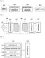
- Fig. 3is a block diagram of components of the monitoring unit according to an embodiment of the present invention.
- the monitoring unit 220may be configured to include a detecting unit 221, a charge monitoring unit 222, a control unit 223, and an alarm unit 224.
- the detecting unit 221may detect at least one of current and voltage of the wireless power transmitting coil 210.
- the detecting unit 221may be configured to include, for example, a current transformer, an electric transformer, and a transformer and to detect current which is flowing through the transmitting coil 210 or voltage which is applied to the transmitting coil 210 and deliver it to the charge monitoring unit 222.
- the charge monitoring unit 222may determine that wireless charging is completed when time during which at least one of the detected current and voltage is kept below a charging threshold value exceeds a first predetermined time. When the charging is completed, current flowing through the transmitting coil 210 is decreased as compared to the time that the charging is in progress. When at least one of the current and voltage which is detected at the detecting unit 221 falls below the charging threshold value, the charge monitoring unit 222 may determine whether the wireless charging has been completed by determining duration during which the detected current or voltage falls below the charging threshold value.
- the charging threshold valuemay be set to 90% or less of a charging current value or charging voltage value, and may be set differently depending on a type of the wireless power receiving apparatus.
- the charging thresholdmay be set differently based on the respective current and voltage.
- the charge monitoring unit 222may independently compare the detected current value and the detected voltage value with each respective charging threshold value for the current and the voltage and determine the detected current value and the detected voltage value.
- the first predetermined timeis for determining duration during which at least one of the current and the voltage of the receiving coil 210 is shown to be below the charging threshold value, and may be set differently depending on a type of the wireless power receiving apparatus 300.
- the charge monitoring unit 222may compare the received power value which is received from the wireless power receiving apparatus 300 with the reception threshold value, and when the time in which the received power value is kept below the threshold value exceeds a second predetermined time, it may be determined that wireless charging is completed.
- the second predetermined timemay be set differently from the case in which it is determined whether the wireless charging has been completed using the detected current value and voltage value.
- the charge monitoring unit 222may compare the received power value which is received from the wireless power receiving apparatus 300 with the reception threshold value, and when the time in which the received power value is kept below the threshold value exceeds a second threshold time, it may be determined that wireless charging has been completed. That is to say, when all of the detected voltage value, the detected current value, and the received power value satisfy the corresponding conditions, it may be determined that wireless charging has been completed. This can prevent any errors that may occur, due to the high temperature state, noise, or surrounding environmental factors, when determining whether the wireless charging has been completed based only on the detected current value and the detected voltage value.
- the control unit 223may regulate the transmitting voltage when the wireless charging has been completed.
- the control unit 223may, for example, when the wireless charging has been completed, regulate the transmitting voltage by controlling the power source, or regulate the transmitting voltage so as to not apply the transmitting voltage to the transmitting coil by turning off the power source.
- the control unit 223may regulate the transmitting voltage using the detected current value when the wireless charging has been completed, and in this case, the transmitting voltage may be regulated by taking into consideration a reduction rate of the detected current value. That is to say, when the wireless charging has been completed, an amount of the power which can be received at the wireless power receiving apparatus 300 is decreased.
- the control unit 223is able to transmit an amount of the power which is adapted to the amount of the power that can be received by the wireless power receiving apparatus 300 by decreasing the amount of the transmitting voltage in proportion to the detected current value.
- control unit 223may regulate the transmitting voltage using the received power value which is received from the wireless power receiving apparatus 300 when the wireless charging has been completed, and in this case, the transmitting voltage may be regulated by taking into consideration a reduction rate of the received power value.
- the alarm unit 224may output an alarm to the outside based on the control of the control unit 223 when the wireless charging has been completed.
- Fig. 4is a drawing for explaining operation of a wireless power transmitting apparatus according to an embodiment of the present invention.
- the wireless power transmitting apparatusdetects a wireless power receiving apparatus.
- the wireless power transmitting apparatusmay detect the wireless power receiving apparatus, for example, when the wireless power receiving apparatus is placed on the substrate, or when the wireless power receiving apparatus is located within a certain distance (S401).
- the wireless power transmitting apparatusidentifies the type of detected wireless power receiving apparatus. After identifying the detected wireless power receiving apparatus, the wireless power transmitting apparatus loads a charging threshold value, a predetermined time, and a reception threshold value of the corresponding apparatus. In the case of detecting a new wireless power receiving apparatus, a new charging threshold value, a new predetermined time, and a new reception threshold value can be set (S402).
- the wireless power transmitting apparatussends a wireless power for charging the detected wireless power receiving apparatus (S403).
- the detecting unitdetects at least one of current and voltage flowing through the receiving coil and delivers the detected current or voltage to the charge monitoring unit (S404).
- the charge monitoring unitdetermines whether at least one of the detected current and voltage is shown to be below the charging threshold value (S405).
- the charge monitoring unitdetermines whether the duration during which at least one of the detected current and voltage is shown to be below the charging threshold value exceeds the first predetermined time, and if the first predetermined time is exceeded, it is determined that the charging of the wireless power receiving apparatus has been completed (S406).
- control unitWhen it is determined that the charging of the wireless power receiving apparatus has been completed, the control unit regulates voltage which is applied to the transmitting coil, and controls the alarm unit so as to be able to output an alarm to the outside (S407).
- Fig. 5is a drawing for explaining operation of a wireless power transmitting apparatus according to another embodiment of the present invention.
- the wireless power transmitting apparatusdetects a wireless power receiving apparatus.
- the wireless power transmitting apparatusmay detect the wireless power receiving apparatus, for example, when the wireless power receiving apparatus is placed on the substrate, or when the wireless power receiving apparatus is located within a certain distance (S501).
- the wireless power transmitting apparatusidentifies the type of the detected wireless power receiving apparatus. After identifying the detected wireless power receiving apparatus, the wireless power transmitting apparatus loads a charging threshold value, a predetermined time, and a reception threshold value of the corresponding apparatus. In the case of detecting a new wireless power receiving apparatus, a new charging threshold value, a new predetermined time, and a new reception threshold value can be set (S502).
- the wireless power transmitting apparatussends wireless power for charging the detected wireless power receiving apparatus (S503).
- the detecting unitdetects at least one of current and voltage flowing through the receiving coil and delivers the detected current or voltage to the charge monitoring unit (S504).
- the charge monitoring unitdetermines whether at least one of the detected current and voltage is shown to be below the charging threshold value (S505).
- the charge monitoring unitdetermines whether the received power value which is received from the wireless power receiving apparatus is shown to be below the reception threshold value (S506).
- the charge monitoring unitdetermines whether the duration during which at least one of the detected current and voltage is shown to be below the charging threshold value and the duration during which the received power value which is received from the wireless power receiving apparatus exceeds the first predetermined time and the second predetermined time, and if one of the predetermined times has been exceeded respectively, it is determined that the charging of the wireless power receiving apparatus has been completed (S507).
- control unitWhen it is determined that the charging of the wireless power receiving apparatus has been completed, the control unit regulates voltage which is applied to the transmitting coil, and controls the alarm unit so as to be able to output an alarm to outside (S508).
- unitrefers to software or hardware such as FPGA (field-programmable gate array) or ASIC, and components which are refers to as “unit” perform certain roles.
- unitis not limited to software or hardware.
- a "Unit”may be configured to be placed in a storage medium which is capable of addressing and may be configured to operate one or more processors. Accordingly, by way of an example, a “unit” includes components such as software components, object-oriented software components, class components and task components, and functions, attributes, procedures, subroutines, segments of a program code, drivers, firmware, microcode, circuitry, data, databases, data structures, tables, arrays, and variables.
- components and “units”may combine to be a smaller number of components and “units” or be separated as additional components and “units”. Moreover, the components and “units” may be made to operate one or more CPUs within a device or a secured multimedia card.
Landscapes
- Engineering & Computer Science (AREA)
- Computer Networks & Wireless Communication (AREA)
- Power Engineering (AREA)
- Signal Processing (AREA)
- Charge And Discharge Circuits For Batteries Or The Like (AREA)
Description
- The present invention relates to a wireless power transmitting apparatus and a wireless charging system which includes the wireless power transmitting apparatus.
- Wireless charging technology is a technology which is able to wirelessly supply and receive power without a connector for delivering the power. There is wireless charging technology such as an electromagnetic induction method using a coil, a wireless power transferring method converts electric energy into microwaves and delivers the microwaves, and a method using resonance.
- The electromagnetic induction method is a method in which power is transferred between a first coil and a second coil using electricity-generating properties as a result of moving a magnet toward the coils to generate an induction current. That is to say, it is a method in which a magnetic field is generated at a transmitting end, and instead of a magnet, the magnetic field generates energy at a receiving end, in which this phenomenon is called a magnetic induction phenomenon. Because the efficiency of energy transfer of the electromagnetic induction method is excellent, the electromagnetic induction method has been used widely and has been adapted to various devices.
- A resonance method uses resonating properties of sound, such as when a tuning fork is resonated, a wine glass next to the tuning fork is resonated with the same frequency as that of the tuning fork. Nevertheless, the resonance method resonates an electromagnetic wave containing electric energy, instead of resonating the sound. RF/Micro wave radiation method is a power transferring method in which power energy is converted into microwaves which is advantageous for wireless transfer and delivering energy. In the aforementioned method, a concept of a signal is not that which is used for wireless communication such as a radio or a wireless telephone, but a concept of sending electric energy; i.e. not a signal sent with a carrier wave in normal communication, but the wireless power transfer which only sends a carrier wave. In wireless charging, when an apparatus for wireless power charging is detected at a wireless power transmitting side, the power for the charging is transferred so as to supply the power to the apparatus and it is identified whether the apparatus is for wireless charging. If the apparatus is identified as an apparatus for wireless charging, power transfer is negotiated and then a wireless power receiving apparatus starts to be charged. Next, the wireless power transmitting apparatus supplies the power to the corresponding wireless power receiving apparatus, however, there is a problem in that there is no means for identifying directly whether the charging of the wireless power receiving apparatus is completed so that after completing of charging, the power continues to be supplied to the wireless power receiving apparatus. The efficiency of the power which is supplied after completion of charging is significantly lowered and results in unnecessary waste of power. Features related to the subject-matter of claim 1 are known from
JP 2013 070581 A JP 5 639 693 B1 US 2013/300206 A1 . - Embodiments of the present invention provide a wireless power transmitting apparatus capable of monitoring a charging state of a wireless power receiving end at a wireless power transmitting end in real time and determining a fully-charged state on its own and a wireless charging system including the wireless power transmitting apparatus.
- Furthermore, embodiments of the present invention provide a wireless power transmitting apparatus capable of preventing unnecessary loss of power by controlling an amount of transmitting power when wireless charging has been completed and a wireless charging system including the wireless power transmitting apparatus.
- Furthermore, embodiments of the present invention provide a wireless power transmitting apparatus capable of preventing misjudgment of the completion of charging, which may be caused by environmental factors such as high temperature at a wireless power receiving end and a wireless charging system including the wireless power transmitting apparatus.
- According to one embodiment of the present invention, a wireless power transmitting apparatus is disclosed which includes: a detecting unit which detects at least one of current and voltage of a wireless power transmitting coil; and a charge monitoring unit which determines when wireless charging has been completed in the case that at least one of the detected current and voltage is shown to be below a charge threshold value over a set amount of time.
- A control unit may further be included which regulates transmitting voltage when the wireless charging has been completed.
- The control unit may regulate the transmitted voltage using the detected current value when the wireless charging has been completed.
- The control unit may regulate the transmitted voltage based on a reduction rate of the detected current value when the wireless charging has been completed.
- An alarm unit may be configured to further be included which outputs an alarm to the outside when the wireless charging has been completed.
- The charge monitoring unit receives received power from a wireless power receiving apparatus, and when the received power value is shown to be below a reception threshold value during the set period of time, it may be determined that the wireless charging has been completed.
- The charge monitoring unit may determine whether the wireless charging has been completed by comparing the received power value with the reception threshold value when at least one of the detected current and voltage is shown to be below the charging threshold value over a set amount of time.
- A control unit may further be included which regulates transmitted voltage when the wireless charging has been completed.
- The control unit may regulate the transmitted voltage based on the received power value when the wireless charging has been completed.
- The control unit may regulate the transmitting voltage based on a reduction rate of the received power value when the wireless charging has been completed.
- The charging threshold value may be set to 90% or less of a charge value in a state in which the charging is in progress.
- The wireless power transmitting apparatus and the wireless charging system including the wireless power transmitting apparatus of the present invention are able to monitor a charging state of a wireless power receiving end at a wireless power transmitting end and determine a fully-charged state on their own.
- Further, it is possible to prevent unnecessary loss of power by controlling an amount of transmitting power when wireless charging is completed.
- Further, it is possible to prevent misjudgment of charge completion which may be caused by environmental factors such as high temperature at a wireless power receiving end.
Fig. 1 is a block diagram of components of a wireless charging system according to an embodiment of the present invention,Fig. 2 is a conceptual diagram of a wireless charging system according to an embodiment of the present invention,Fig. 3 is a block diagram of components of a wireless power transmitting apparatus according to an embodiment of the present invention,Fig. 4 is a drawing for explaining operation of a wireless power transmitting apparatus according to an embodiment of the present invention, andFig. 5 is a drawing for explaining operation of a wireless power transmitting apparatus according to another embodiment of the present invention.- While the invention is open to various modifications and alternative embodiments, specific embodiments thereof are shown by way of example in the drawings and will be described. However, it should be understood that there is no intention to limit the invention to the particular embodiments disclosed, but on the contrary, the invention is to cover all modifications, equivalents, and alternatives falling within the spirit and scope of the invention.
- It will be understood that, although the terms including ordinal numbers such as "first," "second," etc. may be used herein to describe various elements, these elements are not limited by these terms. These terms are only used to distinguish one element from another. For example, a second element could be termed a first element without departing from the teachings of the present inventive concept, and similarly a first element could be also termed a second element. The term "and/or" includes any and all combination of one or more of the associated items listed.
- When an element is referred to as being "connected to" or "coupled with" another element, it can not only be directly connected or coupled to the other element, but also it can be understood that intervening elements may be present. In contrast, when an element is referred to as being "directly connected to" or "directly coupled with" another element, there are no intervening elements present.
- The terminology used herein is for the purpose of describing particular embodiments only and is not intended to limit the present inventive concept. As used herein, the singular forms "a," "an," and "the," are intended to include the plural forms as well, unless the context clearly indicates otherwise. It will be further understood that the terms "comprises" and/or "comprising," when used in this specification, specify the presence of stated features, integers, steps, operations, elements, and/or components, but do not preclude the presence or addition of one or more other features, integers, steps, operations, elements, components, and/or groups thereof.
- Unless otherwise defined, all terms including technical and scientific terms used herein have the same meaning as commonly understood by one of ordinary skill in the art to which this inventive concept belongs. It will be further understood that terms, such as those defined in commonly used dictionaries, should be interpreted as having a meaning that is consistent with their meaning in the context of the relevant art and will not be interpreted in an idealized or overly formal sense unless expressly so defined herein.
- Hereinafter, embodiments of the present invention will be described in detail with reference to the accompanying drawings, and regardless of the numbers in the drawings, the same or corresponding elements will be assigned with the same numbers and overlapping descriptions will be omitted.
Fig. 1 is a block diagram of components of a wireless charging system according to an embodiment of the present invention, andFig. 2 is a conceptual diagram of a wireless charging system according to an embodiment of the present invention.- Referring to
Fig. 1 and Fig. 2 , a wireless charging system 10 includes apower source 100, a wirelesspower transmitting apparatus 200, a wirelesspower receiving apparatus 300, and aload terminal 400. - The wireless
power transmitting apparatus 200 is connected to thepower source 100 and receives power from thepower source 100. The wirelesspower transmitting apparatus 200 wirelessly transmits power to the wirelesspower receiving apparatus 300. In this case, the wirelesspower transmitting apparatus 200 may transmit power using an electromagnetic induction method or a resonance method. Although thepower source 100 and the wirelesspower transmitting apparatus 200 are illustrated as separated elements, the structure is not limited thereto. Thepower source 100 may be included in the wirelesspower transmitting apparatus 200. - The wireless
power receiving apparatus 300 wirelessly receives power from the wirelesspower transmitting apparatus 200. The wirelesspower receiving apparatus 300 may also receive power using the electromagnetic induction method or the resonance method. Furthermore, the wirelesspower receiving apparatus 300 provides the received power to theload terminal 400. Theload terminal 400 may be a battery or a device with a built-in battery. Theload terminal 400 and the wirelesspower receiving apparatus 300 are illustrated as separated elements, the structure is not limited thereto. Theload terminal 400 may be included in the wirelesspower receiving apparatus 300. - The wireless
power transmitting apparatus 200 may include a transmittingcoil 210 and amonitoring unit 220. The wirelesspower receiving apparatus 300 may include a receivingcoil 310 and arectifying unit 320. - The
power source 100 may generate an alternating current (AC) power having a predetermined frequency and supply it to the transmittingcoil 210 of the wirelesspower transmitting apparatus 200. - Further, the alternating current generated by the transmitting
coil 210 may be delivered to the receivingcoil 310 which is inductively coupled to the transmittingcoil 210. On the other hand, the power delivered to the transmittingcoil 210 may be delivered to the wirelesspower receiving apparatus 300 having the same resonance frequency as the wirelesspower transmitting apparatus 200 through a frequency resonance method. The power may be transferred between two impedance matched LC circuits through resonance. - The power delivered to the receiving
coil 310 may be rectified through the rectifyingunit 320 and delivered to theload terminal 400 using the electromagnetic induction method or the resonance method. - The
monitoring unit 220 may monitor the charging state of the wireless power receiving apparatus. Fig. 3 is a block diagram of components of the monitoring unit according to an embodiment of the present invention.- Referring to
Fig. 3 , themonitoring unit 220 according to an embodiment of the present invention may be configured to include a detectingunit 221, acharge monitoring unit 222, acontrol unit 223, and analarm unit 224. - The detecting
unit 221 may detect at least one of current and voltage of the wirelesspower transmitting coil 210. The detectingunit 221 may be configured to include, for example, a current transformer, an electric transformer, and a transformer and to detect current which is flowing through the transmittingcoil 210 or voltage which is applied to the transmittingcoil 210 and deliver it to thecharge monitoring unit 222. - The
charge monitoring unit 222 may determine that wireless charging is completed when time during which at least one of the detected current and voltage is kept below a charging threshold value exceeds a first predetermined time. When the charging is completed, current flowing through the transmittingcoil 210 is decreased as compared to the time that the charging is in progress. When at least one of the current and voltage which is detected at the detectingunit 221 falls below the charging threshold value, thecharge monitoring unit 222 may determine whether the wireless charging has been completed by determining duration during which the detected current or voltage falls below the charging threshold value. - The charging threshold value, for example, may be set to 90% or less of a charging current value or charging voltage value, and may be set differently depending on a type of the wireless power receiving apparatus. The charging threshold may be set differently based on the respective current and voltage. The
charge monitoring unit 222 may independently compare the detected current value and the detected voltage value with each respective charging threshold value for the current and the voltage and determine the detected current value and the detected voltage value. In addition, the first predetermined time is for determining duration during which at least one of the current and the voltage of the receivingcoil 210 is shown to be below the charging threshold value, and may be set differently depending on a type of the wirelesspower receiving apparatus 300. - However, in contrast, the
charge monitoring unit 222 may compare the received power value which is received from the wirelesspower receiving apparatus 300 with the reception threshold value, and when the time in which the received power value is kept below the threshold value exceeds a second predetermined time, it may be determined that wireless charging is completed. In this case, the second predetermined time may be set differently from the case in which it is determined whether the wireless charging has been completed using the detected current value and voltage value. - In addition, when a time in which at least one of the current and the voltage is kept below the charging threshold value exceeds the first predetermined time, the
charge monitoring unit 222 may compare the received power value which is received from the wirelesspower receiving apparatus 300 with the reception threshold value, and when the time in which the received power value is kept below the threshold value exceeds a second threshold time, it may be determined that wireless charging has been completed. That is to say, when all of the detected voltage value, the detected current value, and the received power value satisfy the corresponding conditions, it may be determined that wireless charging has been completed. This can prevent any errors that may occur, due to the high temperature state, noise, or surrounding environmental factors, when determining whether the wireless charging has been completed based only on the detected current value and the detected voltage value. - The
control unit 223 may regulate the transmitting voltage when the wireless charging has been completed. Thecontrol unit 223 may, for example, when the wireless charging has been completed, regulate the transmitting voltage by controlling the power source, or regulate the transmitting voltage so as to not apply the transmitting voltage to the transmitting coil by turning off the power source. - The
control unit 223 may regulate the transmitting voltage using the detected current value when the wireless charging has been completed, and in this case, the transmitting voltage may be regulated by taking into consideration a reduction rate of the detected current value. That is to say, when the wireless charging has been completed, an amount of the power which can be received at the wirelesspower receiving apparatus 300 is decreased. Thecontrol unit 223 is able to transmit an amount of the power which is adapted to the amount of the power that can be received by the wirelesspower receiving apparatus 300 by decreasing the amount of the transmitting voltage in proportion to the detected current value. - In addition, the
control unit 223 may regulate the transmitting voltage using the received power value which is received from the wirelesspower receiving apparatus 300 when the wireless charging has been completed, and in this case, the transmitting voltage may be regulated by taking into consideration a reduction rate of the received power value. - The
alarm unit 224 may output an alarm to the outside based on the control of thecontrol unit 223 when the wireless charging has been completed. Fig. 4 is a drawing for explaining operation of a wireless power transmitting apparatus according to an embodiment of the present invention.- Firstly, the wireless power transmitting apparatus detects a wireless power receiving apparatus. The wireless power transmitting apparatus may detect the wireless power receiving apparatus, for example, when the wireless power receiving apparatus is placed on the substrate, or when the wireless power receiving apparatus is located within a certain distance (S401).
- The wireless power transmitting apparatus identifies the type of detected wireless power receiving apparatus. After identifying the detected wireless power receiving apparatus, the wireless power transmitting apparatus loads a charging threshold value, a predetermined time, and a reception threshold value of the corresponding apparatus. In the case of detecting a new wireless power receiving apparatus, a new charging threshold value, a new predetermined time, and a new reception threshold value can be set (S402).
- The wireless power transmitting apparatus sends a wireless power for charging the detected wireless power receiving apparatus (S403).
- The detecting unit detects at least one of current and voltage flowing through the receiving coil and delivers the detected current or voltage to the charge monitoring unit (S404).
- The charge monitoring unit determines whether at least one of the detected current and voltage is shown to be below the charging threshold value (S405).
- When at least one of the detected current and voltage is shown to be below the charging threshold value, the charge monitoring unit determines whether the duration during which at least one of the detected current and voltage is shown to be below the charging threshold value exceeds the first predetermined time, and if the first predetermined time is exceeded, it is determined that the charging of the wireless power receiving apparatus has been completed (S406).
- When it is determined that the charging of the wireless power receiving apparatus has been completed, the control unit regulates voltage which is applied to the transmitting coil, and controls the alarm unit so as to be able to output an alarm to the outside (S407).
Fig. 5 is a drawing for explaining operation of a wireless power transmitting apparatus according to another embodiment of the present invention.- Firstly, the wireless power transmitting apparatus detects a wireless power receiving apparatus. The wireless power transmitting apparatus may detect the wireless power receiving apparatus, for example, when the wireless power receiving apparatus is placed on the substrate, or when the wireless power receiving apparatus is located within a certain distance (S501).
- The wireless power transmitting apparatus identifies the type of the detected wireless power receiving apparatus. After identifying the detected wireless power receiving apparatus, the wireless power transmitting apparatus loads a charging threshold value, a predetermined time, and a reception threshold value of the corresponding apparatus. In the case of detecting a new wireless power receiving apparatus, a new charging threshold value, a new predetermined time, and a new reception threshold value can be set (S502).
- The wireless power transmitting apparatus sends wireless power for charging the detected wireless power receiving apparatus (S503).
- The detecting unit detects at least one of current and voltage flowing through the receiving coil and delivers the detected current or voltage to the charge monitoring unit (S504).
- The charge monitoring unit determines whether at least one of the detected current and voltage is shown to be below the charging threshold value (S505).
- When at least one of the detected current and voltage is shown to be below the charging threshold value, the charge monitoring unit determines whether the received power value which is received from the wireless power receiving apparatus is shown to be below the reception threshold value (S506).
- The charge monitoring unit determines whether the duration during which at least one of the detected current and voltage is shown to be below the charging threshold value and the duration during which the received power value which is received from the wireless power receiving apparatus exceeds the first predetermined time and the second predetermined time, and if one of the predetermined times has been exceeded respectively, it is determined that the charging of the wireless power receiving apparatus has been completed (S507).
- When it is determined that the charging of the wireless power receiving apparatus has been completed, the control unit regulates voltage which is applied to the transmitting coil, and controls the alarm unit so as to be able to output an alarm to outside (S508).
- The term "unit" used herein refers to software or hardware such as FPGA (field-programmable gate array) or ASIC, and components which are refers to as "unit" perform certain roles. However, the term "unit" is not limited to software or hardware. A "Unit" may be configured to be placed in a storage medium which is capable of addressing and may be configured to operate one or more processors. Accordingly, by way of an example, a "unit" includes components such as software components, object-oriented software components, class components and task components, and functions, attributes, procedures, subroutines, segments of a program code, drivers, firmware, microcode, circuitry, data, databases, data structures, tables, arrays, and variables. Functions provided within the components and "units" may combine to be a smaller number of components and "units" or be separated as additional components and "units". Moreover, the components and "units" may be made to operate one or more CPUs within a device or a secured multimedia card.
- Although exemplary embodiments of the present invention have been referenced and described above, it will be understood that it is possible for those of ordinary skill in the art to implement modifications and variations on the present invention without departing from the scope of the present invention listed in the following appended claims.
Claims (11)
- A wireless power transmitting apparatus, comprising:a detecting unit (221) which is configured to detect at least one of current and voltage of the wireless power transmitting coil (210); anda charge monitoring unit (222) which is configured to determine that wireless charging has been completed when time during which at least one of the detected current and voltage is kept below a charging threshold value exceeds a first threshold time,wherein the charge monitoring unit (222) is configured to receive a received power from a wireless power receiving apparatus,characterised in that when a time during which at least one of the detected current and voltage is kept below the charging threshold value exceeds the first threshold time, the charge monitoring unit (222) is configured to compare a received power value received from the wireless power receiving apparatus with a reception threshold value, andwhen a time during which the received power value is kept below a reception threshold value exceeds a second threshold time, it is determined that the wireless charging has been completed.
- The wireless power transmitting apparatus of claim 1,
further comprising a control unit (223) which is configured to regulate the transmitting voltage when the wireless charging has been completed. - The wireless power transmitting apparatus of claim 2,
wherein the control unit (223) is configured to regulate the transmitting voltage according to a reduction rate of the detected current value which is detected at the detecting unit (221) when the wireless charging has been completed. - The wireless power transmitting apparatus of claim 1,
further comprising an alarm unit (224) which is configured to output an alarm to an outside when the wireless charging has been completed. - The wireless power transmitting apparatus of claim 1,
wherein the second threshold time is set differently from the first threshold time. - The wireless power transmitting apparatus of claim 2,
wherein the control unit (223) is configured to regulate the transmitting voltage using the received power value when the wireless charging has been completed. - The wireless power transmitting apparatus of claim 6,
wherein the control unit (223) is configured to regulate the transmitting voltage using a reduction rate of the received power value when the wireless charging has been completed. - The wireless power transmitting apparatus of claim 3,
wherein when the wireless charging is completed, the control unit (223) is configured to regulate the transmitting voltage by decreasing the amount of the transmitting voltage in proportion to the detected current value. - The wireless power transmitting apparatus of claim 1,
wherein the charging threshold value is set to 90% or less of a charging current value or a charging voltage value at a state in which the charging is in progress. - The wireless power transmitting apparatus of claim 9,
wherein a ratio of the charging threshold value for the current value and a ratio of the charging threshold value for the voltage value are set differently. - The wireless power transmitting apparatus of claim 1,
wherein after detecting a wireless power receiving apparatus within a certain distance, the wireless power transmitting apparatus is configured to load a charging threshold value, a predetermined time, and a reception threshold value of the corresponding apparatus.
Applications Claiming Priority (2)
| Application Number | Priority Date | Filing Date | Title |
|---|---|---|---|
| KR1020140192398AKR20160080499A (en) | 2014-12-29 | 2014-12-29 | Wireless power transmitting apparatus and wireless charging system comprising the same |
| PCT/KR2015/013938WO2016108480A1 (en) | 2014-12-29 | 2015-12-18 | Wireless power transmission device and wireless charging system comprising same |
Publications (3)
| Publication Number | Publication Date |
|---|---|
| EP3242374A1 EP3242374A1 (en) | 2017-11-08 |
| EP3242374A4 EP3242374A4 (en) | 2018-09-05 |
| EP3242374B1true EP3242374B1 (en) | 2019-10-23 |
Family
ID=56284568
Family Applications (1)
| Application Number | Title | Priority Date | Filing Date |
|---|---|---|---|
| EP15875574.4ANot-in-forceEP3242374B1 (en) | 2014-12-29 | 2015-12-18 | Wireless power transmission device and wireless charging system comprising same |
Country Status (5)
| Country | Link |
|---|---|
| US (1) | US20170359102A1 (en) |
| EP (1) | EP3242374B1 (en) |
| KR (1) | KR20160080499A (en) |
| CN (1) | CN107112810A (en) |
| WO (1) | WO2016108480A1 (en) |
Families Citing this family (2)
| Publication number | Priority date | Publication date | Assignee | Title |
|---|---|---|---|---|
| US10530177B2 (en)* | 2017-03-09 | 2020-01-07 | Cochlear Limited | Multi-loop implant charger |
| JP2023000390A (en) | 2021-06-17 | 2023-01-04 | トヨタ自動車株式会社 | vehicle |
Family Cites Families (17)
| Publication number | Priority date | Publication date | Assignee | Title |
|---|---|---|---|---|
| JP2009273327A (en)* | 2008-05-10 | 2009-11-19 | Sanyo Electric Co Ltd | Battery built-in apparatus and charging cradle |
| JP2010016985A (en)* | 2008-07-03 | 2010-01-21 | Sanyo Electric Co Ltd | Method of data transmission in electric power transmission, and charging stand and battery built-in device using the method |
| US8922329B2 (en)* | 2009-07-23 | 2014-12-30 | Qualcomm Incorporated | Battery charging to extend battery life and improve efficiency |
| JP5564412B2 (en)* | 2010-12-10 | 2014-07-30 | 株式会社日立製作所 | Wireless power transmission system, power transmission device, and power reception device |
| JP5591957B2 (en)* | 2011-01-20 | 2014-09-17 | 株式会社東芝 | Semiconductor device, power transmission device, power reception device, charging system, wireless communication system, and charging method |
| KR20120102316A (en)* | 2011-03-08 | 2012-09-18 | 삼성전자주식회사 | System for wireless power transmission and reception |
| US9444247B2 (en)* | 2011-05-17 | 2016-09-13 | Samsung Electronics Co., Ltd. | Apparatus and method of protecting power receiver of wireless power transmission system |
| JP5690251B2 (en)* | 2011-09-26 | 2015-03-25 | 日立マクセル株式会社 | Resonance type wireless charger |
| KR101951358B1 (en)* | 2011-12-15 | 2019-02-22 | 삼성전자주식회사 | Wireless power transmitter, wireless power receiver and method for controlling each thereof |
| KR101882273B1 (en)* | 2012-05-09 | 2018-07-30 | 삼성전자주식회사 | Method and apparatus for wireless power reception and method and apparatus for wireless power transmission |
| JP5847651B2 (en)* | 2012-06-01 | 2016-01-27 | 株式会社東芝 | Power receiving device and power transmitting / receiving system |
| JP5787830B2 (en)* | 2012-06-01 | 2015-09-30 | 株式会社東芝 | Power receiving device and power transmitting / receiving system |
| KR101882754B1 (en)* | 2012-06-20 | 2018-07-27 | 삼성전자주식회사 | Method for controlling power trasnmitting in wireless charging device and the wireless charging device therefor |
| EP2926465B1 (en)* | 2012-11-29 | 2020-02-12 | Koninklijke Philips N.V. | Wireless inductive power transfer |
| KR101372472B1 (en)* | 2013-05-20 | 2014-03-10 | 엘아이지넥스원 주식회사 | Wireless power transfer apparatus |
| US9843196B2 (en)* | 2013-06-11 | 2017-12-12 | Lg Electronics Inc. | Wireless power transmitter, wireless power receiver and wireless charging system in home appliances |
| JP5639693B1 (en)* | 2013-07-09 | 2014-12-10 | 日東電工株式会社 | Wireless power transmission device and method for controlling power supply of wireless power transmission device |
- 2014
- 2014-12-29KRKR1020140192398Apatent/KR20160080499A/ennot_activeWithdrawn
- 2015
- 2015-12-18CNCN201580071483.7Apatent/CN107112810A/enactivePending
- 2015-12-18USUS15/536,205patent/US20170359102A1/ennot_activeAbandoned
- 2015-12-18EPEP15875574.4Apatent/EP3242374B1/ennot_activeNot-in-force
- 2015-12-18WOPCT/KR2015/013938patent/WO2016108480A1/enactiveApplication Filing
Non-Patent Citations (1)
| Title |
|---|
| None* |
Also Published As
| Publication number | Publication date |
|---|---|
| US20170359102A1 (en) | 2017-12-14 |
| CN107112810A (en) | 2017-08-29 |
| WO2016108480A1 (en) | 2016-07-07 |
| KR20160080499A (en) | 2016-07-08 |
| EP3242374A4 (en) | 2018-09-05 |
| EP3242374A1 (en) | 2017-11-08 |
Similar Documents
| Publication | Publication Date | Title |
|---|---|---|
| US10944294B2 (en) | Method for transmitting signal by wireless power transmitter in wireless charging system, wireless power transmitter and wireless power receiver | |
| EP2932616B1 (en) | Resolving communications in a wireless power system with co-located transmitters | |
| EP3180834B1 (en) | Method for determining cross connection in wireless charging | |
| EP3202009B1 (en) | System and method for prevention of wireless charging cross connection | |
| EP2909918B1 (en) | Wireless power transmitters and receivers, and method for permitting a wireless power receiver by a wireless power transmitter | |
| US9769869B2 (en) | Non-contact type power supply apparatus and non-contact type power supply method | |
| US20190305826A1 (en) | Wireless power transferring method and device therefor | |
| US9941706B2 (en) | Wireless power safety component | |
| US20160126752A1 (en) | Method and apparatus for wireless power transfer | |
| EP3098937B1 (en) | Wirelessly providing power to a fully discharged battery | |
| US20160118805A1 (en) | Wireless power transfer system and method thereof | |
| US20120313447A1 (en) | Method of performing bidirectional communication between transmitter and receiver in wireless power transmission/reception system, the transmitter, and the receiver | |
| US20130200844A1 (en) | Wireless power charging method and apparatus | |
| EP2710707B1 (en) | Power transmitting method and power transmitter for communication with power receiver | |
| US20160118834A1 (en) | Portable radio device adapted to function as a wireless charger | |
| KR101720400B1 (en) | Power delivery device and power delivery/power receiving system | |
| US9515704B2 (en) | Wireless energy receiving apparatus and method, and wireless energy transmitting apparatus | |
| US20140015331A1 (en) | Apparatus and method for wireless power reception | |
| JP6278687B2 (en) | Electronic device, method and program | |
| KR20140023409A (en) | Wireless charging system and method of cotnrolligng the same | |
| EP2747299B1 (en) | Wireless charging apparatus and method | |
| EP3198701B1 (en) | Methods and systems for contactless battery discharging | |
| KR20150050142A (en) | Electronic device | |
| CN110999030A (en) | Wireless charging device, receiver device, and related methods | |
| EP3242374B1 (en) | Wireless power transmission device and wireless charging system comprising same |
Legal Events
| Date | Code | Title | Description |
|---|---|---|---|
| STAA | Information on the status of an ep patent application or granted ep patent | Free format text:STATUS: THE INTERNATIONAL PUBLICATION HAS BEEN MADE | |
| PUAI | Public reference made under article 153(3) epc to a published international application that has entered the european phase | Free format text:ORIGINAL CODE: 0009012 | |
| STAA | Information on the status of an ep patent application or granted ep patent | Free format text:STATUS: REQUEST FOR EXAMINATION WAS MADE | |
| 17P | Request for examination filed | Effective date:20170608 | |
| AK | Designated contracting states | Kind code of ref document:A1 Designated state(s):AL AT BE BG CH CY CZ DE DK EE ES FI FR GB GR HR HU IE IS IT LI LT LU LV MC MK MT NL NO PL PT RO RS SE SI SK SM TR | |
| AX | Request for extension of the european patent | Extension state:BA ME | |
| DAV | Request for validation of the european patent (deleted) | ||
| DAX | Request for extension of the european patent (deleted) | ||
| A4 | Supplementary search report drawn up and despatched | Effective date:20180808 | |
| RIC1 | Information provided on ipc code assigned before grant | Ipc:H02J 7/02 20160101AFI20180727BHEP Ipc:H02J 50/12 20160101ALI20180727BHEP Ipc:H02J 7/00 20060101ALI20180727BHEP Ipc:H04B 5/00 20060101ALI20180727BHEP Ipc:H02J 5/00 20160101ALI20180727BHEP | |
| GRAP | Despatch of communication of intention to grant a patent | Free format text:ORIGINAL CODE: EPIDOSNIGR1 | |
| STAA | Information on the status of an ep patent application or granted ep patent | Free format text:STATUS: GRANT OF PATENT IS INTENDED | |
| INTG | Intention to grant announced | Effective date:20190718 | |
| GRAS | Grant fee paid | Free format text:ORIGINAL CODE: EPIDOSNIGR3 | |
| GRAA | (expected) grant | Free format text:ORIGINAL CODE: 0009210 | |
| STAA | Information on the status of an ep patent application or granted ep patent | Free format text:STATUS: THE PATENT HAS BEEN GRANTED | |
| AK | Designated contracting states | Kind code of ref document:B1 Designated state(s):AL AT BE BG CH CY CZ DE DK EE ES FI FR GB GR HR HU IE IS IT LI LT LU LV MC MK MT NL NO PL PT RO RS SE SI SK SM TR | |
| REG | Reference to a national code | Ref country code:GB Ref legal event code:FG4D | |
| REG | Reference to a national code | Ref country code:CH Ref legal event code:EP | |
| REG | Reference to a national code | Ref country code:IE Ref legal event code:FG4D | |
| REG | Reference to a national code | Ref country code:DE Ref legal event code:R096 Ref document number:602015040522 Country of ref document:DE | |
| REG | Reference to a national code | Ref country code:AT Ref legal event code:REF Ref document number:1194766 Country of ref document:AT Kind code of ref document:T Effective date:20191115 | |
| REG | Reference to a national code | Ref country code:NL Ref legal event code:MP Effective date:20191023 | |
| REG | Reference to a national code | Ref country code:LT Ref legal event code:MG4D | |
| PG25 | Lapsed in a contracting state [announced via postgrant information from national office to epo] | Ref country code:PT Free format text:LAPSE BECAUSE OF FAILURE TO SUBMIT A TRANSLATION OF THE DESCRIPTION OR TO PAY THE FEE WITHIN THE PRESCRIBED TIME-LIMIT Effective date:20200224 Ref country code:BG Free format text:LAPSE BECAUSE OF FAILURE TO SUBMIT A TRANSLATION OF THE DESCRIPTION OR TO PAY THE FEE WITHIN THE PRESCRIBED TIME-LIMIT Effective date:20200123 Ref country code:FI Free format text:LAPSE BECAUSE OF FAILURE TO SUBMIT A TRANSLATION OF THE DESCRIPTION OR TO PAY THE FEE WITHIN THE PRESCRIBED TIME-LIMIT Effective date:20191023 Ref country code:GR Free format text:LAPSE BECAUSE OF FAILURE TO SUBMIT A TRANSLATION OF THE DESCRIPTION OR TO PAY THE FEE WITHIN THE PRESCRIBED TIME-LIMIT Effective date:20200124 Ref country code:NO Free format text:LAPSE BECAUSE OF FAILURE TO SUBMIT A TRANSLATION OF THE DESCRIPTION OR TO PAY THE FEE WITHIN THE PRESCRIBED TIME-LIMIT Effective date:20200123 Ref country code:LV Free format text:LAPSE BECAUSE OF FAILURE TO SUBMIT A TRANSLATION OF THE DESCRIPTION OR TO PAY THE FEE WITHIN THE PRESCRIBED TIME-LIMIT Effective date:20191023 Ref country code:SE Free format text:LAPSE BECAUSE OF FAILURE TO SUBMIT A TRANSLATION OF THE DESCRIPTION OR TO PAY THE FEE WITHIN THE PRESCRIBED TIME-LIMIT Effective date:20191023 Ref country code:PL Free format text:LAPSE BECAUSE OF FAILURE TO SUBMIT A TRANSLATION OF THE DESCRIPTION OR TO PAY THE FEE WITHIN THE PRESCRIBED TIME-LIMIT Effective date:20191023 Ref country code:NL Free format text:LAPSE BECAUSE OF FAILURE TO SUBMIT A TRANSLATION OF THE DESCRIPTION OR TO PAY THE FEE WITHIN THE PRESCRIBED TIME-LIMIT Effective date:20191023 Ref country code:LT Free format text:LAPSE BECAUSE OF FAILURE TO SUBMIT A TRANSLATION OF THE DESCRIPTION OR TO PAY THE FEE WITHIN THE PRESCRIBED TIME-LIMIT Effective date:20191023 | |
| PG25 | Lapsed in a contracting state [announced via postgrant information from national office to epo] | Ref country code:RS Free format text:LAPSE BECAUSE OF FAILURE TO SUBMIT A TRANSLATION OF THE DESCRIPTION OR TO PAY THE FEE WITHIN THE PRESCRIBED TIME-LIMIT Effective date:20191023 Ref country code:HR Free format text:LAPSE BECAUSE OF FAILURE TO SUBMIT A TRANSLATION OF THE DESCRIPTION OR TO PAY THE FEE WITHIN THE PRESCRIBED TIME-LIMIT Effective date:20191023 Ref country code:IS Free format text:LAPSE BECAUSE OF FAILURE TO SUBMIT A TRANSLATION OF THE DESCRIPTION OR TO PAY THE FEE WITHIN THE PRESCRIBED TIME-LIMIT Effective date:20200224 | |
| PG25 | Lapsed in a contracting state [announced via postgrant information from national office to epo] | Ref country code:AL Free format text:LAPSE BECAUSE OF FAILURE TO SUBMIT A TRANSLATION OF THE DESCRIPTION OR TO PAY THE FEE WITHIN THE PRESCRIBED TIME-LIMIT Effective date:20191023 | |
| REG | Reference to a national code | Ref country code:DE Ref legal event code:R119 Ref document number:602015040522 Country of ref document:DE | |
| PG2D | Information on lapse in contracting state deleted | Ref country code:IS | |
| PG25 | Lapsed in a contracting state [announced via postgrant information from national office to epo] | Ref country code:DK Free format text:LAPSE BECAUSE OF FAILURE TO SUBMIT A TRANSLATION OF THE DESCRIPTION OR TO PAY THE FEE WITHIN THE PRESCRIBED TIME-LIMIT Effective date:20191023 Ref country code:EE Free format text:LAPSE BECAUSE OF FAILURE TO SUBMIT A TRANSLATION OF THE DESCRIPTION OR TO PAY THE FEE WITHIN THE PRESCRIBED TIME-LIMIT Effective date:20191023 Ref country code:RO Free format text:LAPSE BECAUSE OF FAILURE TO SUBMIT A TRANSLATION OF THE DESCRIPTION OR TO PAY THE FEE WITHIN THE PRESCRIBED TIME-LIMIT Effective date:20191023 Ref country code:CZ Free format text:LAPSE BECAUSE OF FAILURE TO SUBMIT A TRANSLATION OF THE DESCRIPTION OR TO PAY THE FEE WITHIN THE PRESCRIBED TIME-LIMIT Effective date:20191023 Ref country code:ES Free format text:LAPSE BECAUSE OF FAILURE TO SUBMIT A TRANSLATION OF THE DESCRIPTION OR TO PAY THE FEE WITHIN THE PRESCRIBED TIME-LIMIT Effective date:20191023 Ref country code:IS Free format text:LAPSE BECAUSE OF FAILURE TO SUBMIT A TRANSLATION OF THE DESCRIPTION OR TO PAY THE FEE WITHIN THE PRESCRIBED TIME-LIMIT Effective date:20200223 | |
| REG | Reference to a national code | Ref country code:CH Ref legal event code:PL | |
| REG | Reference to a national code | Ref country code:AT Ref legal event code:MK05 Ref document number:1194766 Country of ref document:AT Kind code of ref document:T Effective date:20191023 | |
| REG | Reference to a national code | Ref country code:BE Ref legal event code:MM Effective date:20191231 | |
| PLBE | No opposition filed within time limit | Free format text:ORIGINAL CODE: 0009261 | |
| STAA | Information on the status of an ep patent application or granted ep patent | Free format text:STATUS: NO OPPOSITION FILED WITHIN TIME LIMIT | |
| PG25 | Lapsed in a contracting state [announced via postgrant information from national office to epo] | Ref country code:IT Free format text:LAPSE BECAUSE OF FAILURE TO SUBMIT A TRANSLATION OF THE DESCRIPTION OR TO PAY THE FEE WITHIN THE PRESCRIBED TIME-LIMIT Effective date:20191023 Ref country code:SM Free format text:LAPSE BECAUSE OF FAILURE TO SUBMIT A TRANSLATION OF THE DESCRIPTION OR TO PAY THE FEE WITHIN THE PRESCRIBED TIME-LIMIT Effective date:20191023 Ref country code:SK Free format text:LAPSE BECAUSE OF FAILURE TO SUBMIT A TRANSLATION OF THE DESCRIPTION OR TO PAY THE FEE WITHIN THE PRESCRIBED TIME-LIMIT Effective date:20191023 Ref country code:MC Free format text:LAPSE BECAUSE OF FAILURE TO SUBMIT A TRANSLATION OF THE DESCRIPTION OR TO PAY THE FEE WITHIN THE PRESCRIBED TIME-LIMIT Effective date:20191023 | |
| GBPC | Gb: european patent ceased through non-payment of renewal fee | Effective date:20200123 | |
| 26N | No opposition filed | Effective date:20200724 | |
| PG25 | Lapsed in a contracting state [announced via postgrant information from national office to epo] | Ref country code:DE Free format text:LAPSE BECAUSE OF NON-PAYMENT OF DUE FEES Effective date:20200701 Ref country code:LU Free format text:LAPSE BECAUSE OF NON-PAYMENT OF DUE FEES Effective date:20191218 Ref country code:GB Free format text:LAPSE BECAUSE OF NON-PAYMENT OF DUE FEES Effective date:20200123 Ref country code:IE Free format text:LAPSE BECAUSE OF NON-PAYMENT OF DUE FEES Effective date:20191218 Ref country code:FR Free format text:LAPSE BECAUSE OF NON-PAYMENT OF DUE FEES Effective date:20191223 | |
| PG25 | Lapsed in a contracting state [announced via postgrant information from national office to epo] | Ref country code:BE Free format text:LAPSE BECAUSE OF NON-PAYMENT OF DUE FEES Effective date:20191231 Ref country code:AT Free format text:LAPSE BECAUSE OF FAILURE TO SUBMIT A TRANSLATION OF THE DESCRIPTION OR TO PAY THE FEE WITHIN THE PRESCRIBED TIME-LIMIT Effective date:20191023 Ref country code:LI Free format text:LAPSE BECAUSE OF NON-PAYMENT OF DUE FEES Effective date:20191231 Ref country code:SI Free format text:LAPSE BECAUSE OF FAILURE TO SUBMIT A TRANSLATION OF THE DESCRIPTION OR TO PAY THE FEE WITHIN THE PRESCRIBED TIME-LIMIT Effective date:20191023 Ref country code:CH Free format text:LAPSE BECAUSE OF NON-PAYMENT OF DUE FEES Effective date:20191231 | |
| PG25 | Lapsed in a contracting state [announced via postgrant information from national office to epo] | Ref country code:CY Free format text:LAPSE BECAUSE OF FAILURE TO SUBMIT A TRANSLATION OF THE DESCRIPTION OR TO PAY THE FEE WITHIN THE PRESCRIBED TIME-LIMIT Effective date:20191023 | |
| PG25 | Lapsed in a contracting state [announced via postgrant information from national office to epo] | Ref country code:MT Free format text:LAPSE BECAUSE OF FAILURE TO SUBMIT A TRANSLATION OF THE DESCRIPTION OR TO PAY THE FEE WITHIN THE PRESCRIBED TIME-LIMIT Effective date:20191023 Ref country code:HU Free format text:LAPSE BECAUSE OF FAILURE TO SUBMIT A TRANSLATION OF THE DESCRIPTION OR TO PAY THE FEE WITHIN THE PRESCRIBED TIME-LIMIT; INVALID AB INITIO Effective date:20151218 | |
| PG25 | Lapsed in a contracting state [announced via postgrant information from national office to epo] | Ref country code:TR Free format text:LAPSE BECAUSE OF FAILURE TO SUBMIT A TRANSLATION OF THE DESCRIPTION OR TO PAY THE FEE WITHIN THE PRESCRIBED TIME-LIMIT Effective date:20191023 | |
| PG25 | Lapsed in a contracting state [announced via postgrant information from national office to epo] | Ref country code:MK Free format text:LAPSE BECAUSE OF FAILURE TO SUBMIT A TRANSLATION OF THE DESCRIPTION OR TO PAY THE FEE WITHIN THE PRESCRIBED TIME-LIMIT Effective date:20191023 |