EP3241703B1 - Electric vehicle supply equipment having a socket and a method of charging an electric vehicle - Google Patents
Electric vehicle supply equipment having a socket and a method of charging an electric vehicleDownload PDFInfo
- Publication number
- EP3241703B1 EP3241703B1EP17173126.8AEP17173126AEP3241703B1EP 3241703 B1EP3241703 B1EP 3241703B1EP 17173126 AEP17173126 AEP 17173126AEP 3241703 B1EP3241703 B1EP 3241703B1
- Authority
- EP
- European Patent Office
- Prior art keywords
- power
- vehicle
- processor
- voltage
- electric vehicle
- Prior art date
- Legal status (The legal status is an assumption and is not a legal conclusion. Google has not performed a legal analysis and makes no representation as to the accuracy of the status listed.)
- Active
Links
- 238000000034methodMethods0.000titleclaimsdescription9
- 238000004891communicationMethods0.000claimsdescription18
- 238000012546transferMethods0.000claimsdescription9
- 230000001105regulatory effectEffects0.000claimsdescription6
- 230000001276controlling effectEffects0.000claimsdescription4
- 230000002093peripheral effectEffects0.000claimsdescription4
- 238000001816coolingMethods0.000claims2
- 238000010438heat treatmentMethods0.000claims2
- 230000005611electricityEffects0.000description11
- 230000006870functionEffects0.000description11
- 238000012360testing methodMethods0.000description4
- 230000001413cellular effectEffects0.000description3
- 238000010276constructionMethods0.000description3
- 230000006378damageEffects0.000description3
- 238000010586diagramMethods0.000description3
- 230000003287optical effectEffects0.000description3
- 238000009825accumulationMethods0.000description2
- 238000009434installationMethods0.000description2
- 230000007935neutral effectEffects0.000description2
- 241001541997AllioniaSpecies0.000description1
- BQCADISMDOOEFD-UHFFFAOYSA-NSilverChemical compound[Ag]BQCADISMDOOEFD-UHFFFAOYSA-N0.000description1
- 208000027418Wounds and injuryDiseases0.000description1
- 230000001133accelerationEffects0.000description1
- 238000004378air conditioningMethods0.000description1
- 230000005540biological transmissionEffects0.000description1
- 238000009933burialMethods0.000description1
- 239000003086colorantSubstances0.000description1
- 230000001419dependent effectEffects0.000description1
- 238000013461designMethods0.000description1
- 230000000694effectsEffects0.000description1
- 238000013028emission testingMethods0.000description1
- 208000014674injuryDiseases0.000description1
- 238000007689inspectionMethods0.000description1
- 230000002452interceptive effectEffects0.000description1
- 239000004973liquid crystal related substanceSubstances0.000description1
- NJPPVKZQTLUDBO-UHFFFAOYSA-NnovaluronChemical compoundC1=C(Cl)C(OC(F)(F)C(OC(F)(F)F)F)=CC=C1NC(=O)NC(=O)C1=C(F)C=CC=C1FNJPPVKZQTLUDBO-UHFFFAOYSA-N0.000description1
- 238000012545processingMethods0.000description1
- 239000002994raw materialSubstances0.000description1
- 230000001172regenerating effectEffects0.000description1
- 230000004044responseEffects0.000description1
- 229910052709silverInorganic materials0.000description1
- 239000004332silverSubstances0.000description1
- 239000007787solidSubstances0.000description1
- 230000000007visual effectEffects0.000description1
Images


Classifications
- B—PERFORMING OPERATIONS; TRANSPORTING
- B60—VEHICLES IN GENERAL
- B60L—PROPULSION OF ELECTRICALLY-PROPELLED VEHICLES; SUPPLYING ELECTRIC POWER FOR AUXILIARY EQUIPMENT OF ELECTRICALLY-PROPELLED VEHICLES; ELECTRODYNAMIC BRAKE SYSTEMS FOR VEHICLES IN GENERAL; MAGNETIC SUSPENSION OR LEVITATION FOR VEHICLES; MONITORING OPERATING VARIABLES OF ELECTRICALLY-PROPELLED VEHICLES; ELECTRIC SAFETY DEVICES FOR ELECTRICALLY-PROPELLED VEHICLES
- B60L3/00—Electric devices on electrically-propelled vehicles for safety purposes; Monitoring operating variables, e.g. speed, deceleration or energy consumption
- B60L3/0023—Detecting, eliminating, remedying or compensating for drive train abnormalities, e.g. failures within the drive train
- B60L3/0069—Detecting, eliminating, remedying or compensating for drive train abnormalities, e.g. failures within the drive train relating to the isolation, e.g. ground fault or leak current
- B—PERFORMING OPERATIONS; TRANSPORTING
- B60—VEHICLES IN GENERAL
- B60L—PROPULSION OF ELECTRICALLY-PROPELLED VEHICLES; SUPPLYING ELECTRIC POWER FOR AUXILIARY EQUIPMENT OF ELECTRICALLY-PROPELLED VEHICLES; ELECTRODYNAMIC BRAKE SYSTEMS FOR VEHICLES IN GENERAL; MAGNETIC SUSPENSION OR LEVITATION FOR VEHICLES; MONITORING OPERATING VARIABLES OF ELECTRICALLY-PROPELLED VEHICLES; ELECTRIC SAFETY DEVICES FOR ELECTRICALLY-PROPELLED VEHICLES
- B60L53/00—Methods of charging batteries, specially adapted for electric vehicles; Charging stations or on-board charging equipment therefor; Exchange of energy storage elements in electric vehicles
- B60L53/10—Methods of charging batteries, specially adapted for electric vehicles; Charging stations or on-board charging equipment therefor; Exchange of energy storage elements in electric vehicles characterised by the energy transfer between the charging station and the vehicle
- B60L53/11—DC charging controlled by the charging station, e.g. mode 4
- B—PERFORMING OPERATIONS; TRANSPORTING
- B60—VEHICLES IN GENERAL
- B60L—PROPULSION OF ELECTRICALLY-PROPELLED VEHICLES; SUPPLYING ELECTRIC POWER FOR AUXILIARY EQUIPMENT OF ELECTRICALLY-PROPELLED VEHICLES; ELECTRODYNAMIC BRAKE SYSTEMS FOR VEHICLES IN GENERAL; MAGNETIC SUSPENSION OR LEVITATION FOR VEHICLES; MONITORING OPERATING VARIABLES OF ELECTRICALLY-PROPELLED VEHICLES; ELECTRIC SAFETY DEVICES FOR ELECTRICALLY-PROPELLED VEHICLES
- B60L53/00—Methods of charging batteries, specially adapted for electric vehicles; Charging stations or on-board charging equipment therefor; Exchange of energy storage elements in electric vehicles
- B60L53/10—Methods of charging batteries, specially adapted for electric vehicles; Charging stations or on-board charging equipment therefor; Exchange of energy storage elements in electric vehicles characterised by the energy transfer between the charging station and the vehicle
- B60L53/14—Conductive energy transfer
- B60L53/16—Connectors, e.g. plugs or sockets, specially adapted for charging electric vehicles
- B—PERFORMING OPERATIONS; TRANSPORTING
- B60—VEHICLES IN GENERAL
- B60L—PROPULSION OF ELECTRICALLY-PROPELLED VEHICLES; SUPPLYING ELECTRIC POWER FOR AUXILIARY EQUIPMENT OF ELECTRICALLY-PROPELLED VEHICLES; ELECTRODYNAMIC BRAKE SYSTEMS FOR VEHICLES IN GENERAL; MAGNETIC SUSPENSION OR LEVITATION FOR VEHICLES; MONITORING OPERATING VARIABLES OF ELECTRICALLY-PROPELLED VEHICLES; ELECTRIC SAFETY DEVICES FOR ELECTRICALLY-PROPELLED VEHICLES
- B60L53/00—Methods of charging batteries, specially adapted for electric vehicles; Charging stations or on-board charging equipment therefor; Exchange of energy storage elements in electric vehicles
- B60L53/50—Charging stations characterised by energy-storage or power-generation means
- B60L53/51—Photovoltaic means
- B—PERFORMING OPERATIONS; TRANSPORTING
- B60—VEHICLES IN GENERAL
- B60L—PROPULSION OF ELECTRICALLY-PROPELLED VEHICLES; SUPPLYING ELECTRIC POWER FOR AUXILIARY EQUIPMENT OF ELECTRICALLY-PROPELLED VEHICLES; ELECTRODYNAMIC BRAKE SYSTEMS FOR VEHICLES IN GENERAL; MAGNETIC SUSPENSION OR LEVITATION FOR VEHICLES; MONITORING OPERATING VARIABLES OF ELECTRICALLY-PROPELLED VEHICLES; ELECTRIC SAFETY DEVICES FOR ELECTRICALLY-PROPELLED VEHICLES
- B60L53/00—Methods of charging batteries, specially adapted for electric vehicles; Charging stations or on-board charging equipment therefor; Exchange of energy storage elements in electric vehicles
- B60L53/50—Charging stations characterised by energy-storage or power-generation means
- B60L53/52—Wind-driven generators
- B—PERFORMING OPERATIONS; TRANSPORTING
- B60—VEHICLES IN GENERAL
- B60L—PROPULSION OF ELECTRICALLY-PROPELLED VEHICLES; SUPPLYING ELECTRIC POWER FOR AUXILIARY EQUIPMENT OF ELECTRICALLY-PROPELLED VEHICLES; ELECTRODYNAMIC BRAKE SYSTEMS FOR VEHICLES IN GENERAL; MAGNETIC SUSPENSION OR LEVITATION FOR VEHICLES; MONITORING OPERATING VARIABLES OF ELECTRICALLY-PROPELLED VEHICLES; ELECTRIC SAFETY DEVICES FOR ELECTRICALLY-PROPELLED VEHICLES
- B60L2240/00—Control parameters of input or output; Target parameters
- B60L2240/10—Vehicle control parameters
- B60L2240/34—Cabin temperature
- B—PERFORMING OPERATIONS; TRANSPORTING
- B60—VEHICLES IN GENERAL
- B60L—PROPULSION OF ELECTRICALLY-PROPELLED VEHICLES; SUPPLYING ELECTRIC POWER FOR AUXILIARY EQUIPMENT OF ELECTRICALLY-PROPELLED VEHICLES; ELECTRODYNAMIC BRAKE SYSTEMS FOR VEHICLES IN GENERAL; MAGNETIC SUSPENSION OR LEVITATION FOR VEHICLES; MONITORING OPERATING VARIABLES OF ELECTRICALLY-PROPELLED VEHICLES; ELECTRIC SAFETY DEVICES FOR ELECTRICALLY-PROPELLED VEHICLES
- B60L2240/00—Control parameters of input or output; Target parameters
- B60L2240/60—Navigation input
- B60L2240/62—Vehicle position
- B60L2240/622—Vehicle position by satellite navigation
- B—PERFORMING OPERATIONS; TRANSPORTING
- B60—VEHICLES IN GENERAL
- B60L—PROPULSION OF ELECTRICALLY-PROPELLED VEHICLES; SUPPLYING ELECTRIC POWER FOR AUXILIARY EQUIPMENT OF ELECTRICALLY-PROPELLED VEHICLES; ELECTRODYNAMIC BRAKE SYSTEMS FOR VEHICLES IN GENERAL; MAGNETIC SUSPENSION OR LEVITATION FOR VEHICLES; MONITORING OPERATING VARIABLES OF ELECTRICALLY-PROPELLED VEHICLES; ELECTRIC SAFETY DEVICES FOR ELECTRICALLY-PROPELLED VEHICLES
- B60L2250/00—Driver interactions
- B60L2250/16—Driver interactions by display
- B—PERFORMING OPERATIONS; TRANSPORTING
- B60—VEHICLES IN GENERAL
- B60L—PROPULSION OF ELECTRICALLY-PROPELLED VEHICLES; SUPPLYING ELECTRIC POWER FOR AUXILIARY EQUIPMENT OF ELECTRICALLY-PROPELLED VEHICLES; ELECTRODYNAMIC BRAKE SYSTEMS FOR VEHICLES IN GENERAL; MAGNETIC SUSPENSION OR LEVITATION FOR VEHICLES; MONITORING OPERATING VARIABLES OF ELECTRICALLY-PROPELLED VEHICLES; ELECTRIC SAFETY DEVICES FOR ELECTRICALLY-PROPELLED VEHICLES
- B60L2250/00—Driver interactions
- B60L2250/18—Driver interactions by enquiring driving style
- Y—GENERAL TAGGING OF NEW TECHNOLOGICAL DEVELOPMENTS; GENERAL TAGGING OF CROSS-SECTIONAL TECHNOLOGIES SPANNING OVER SEVERAL SECTIONS OF THE IPC; TECHNICAL SUBJECTS COVERED BY FORMER USPC CROSS-REFERENCE ART COLLECTIONS [XRACs] AND DIGESTS
- Y02—TECHNOLOGIES OR APPLICATIONS FOR MITIGATION OR ADAPTATION AGAINST CLIMATE CHANGE
- Y02T—CLIMATE CHANGE MITIGATION TECHNOLOGIES RELATED TO TRANSPORTATION
- Y02T10/00—Road transport of goods or passengers
- Y02T10/60—Other road transportation technologies with climate change mitigation effect
- Y02T10/70—Energy storage systems for electromobility, e.g. batteries
- Y—GENERAL TAGGING OF NEW TECHNOLOGICAL DEVELOPMENTS; GENERAL TAGGING OF CROSS-SECTIONAL TECHNOLOGIES SPANNING OVER SEVERAL SECTIONS OF THE IPC; TECHNICAL SUBJECTS COVERED BY FORMER USPC CROSS-REFERENCE ART COLLECTIONS [XRACs] AND DIGESTS
- Y02—TECHNOLOGIES OR APPLICATIONS FOR MITIGATION OR ADAPTATION AGAINST CLIMATE CHANGE
- Y02T—CLIMATE CHANGE MITIGATION TECHNOLOGIES RELATED TO TRANSPORTATION
- Y02T10/00—Road transport of goods or passengers
- Y02T10/60—Other road transportation technologies with climate change mitigation effect
- Y02T10/7072—Electromobility specific charging systems or methods for batteries, ultracapacitors, supercapacitors or double-layer capacitors
- Y—GENERAL TAGGING OF NEW TECHNOLOGICAL DEVELOPMENTS; GENERAL TAGGING OF CROSS-SECTIONAL TECHNOLOGIES SPANNING OVER SEVERAL SECTIONS OF THE IPC; TECHNICAL SUBJECTS COVERED BY FORMER USPC CROSS-REFERENCE ART COLLECTIONS [XRACs] AND DIGESTS
- Y02—TECHNOLOGIES OR APPLICATIONS FOR MITIGATION OR ADAPTATION AGAINST CLIMATE CHANGE
- Y02T—CLIMATE CHANGE MITIGATION TECHNOLOGIES RELATED TO TRANSPORTATION
- Y02T10/00—Road transport of goods or passengers
- Y02T10/60—Other road transportation technologies with climate change mitigation effect
- Y02T10/72—Electric energy management in electromobility
- Y—GENERAL TAGGING OF NEW TECHNOLOGICAL DEVELOPMENTS; GENERAL TAGGING OF CROSS-SECTIONAL TECHNOLOGIES SPANNING OVER SEVERAL SECTIONS OF THE IPC; TECHNICAL SUBJECTS COVERED BY FORMER USPC CROSS-REFERENCE ART COLLECTIONS [XRACs] AND DIGESTS
- Y02—TECHNOLOGIES OR APPLICATIONS FOR MITIGATION OR ADAPTATION AGAINST CLIMATE CHANGE
- Y02T—CLIMATE CHANGE MITIGATION TECHNOLOGIES RELATED TO TRANSPORTATION
- Y02T90/00—Enabling technologies or technologies with a potential or indirect contribution to GHG emissions mitigation
- Y02T90/10—Technologies relating to charging of electric vehicles
- Y02T90/12—Electric charging stations
- Y—GENERAL TAGGING OF NEW TECHNOLOGICAL DEVELOPMENTS; GENERAL TAGGING OF CROSS-SECTIONAL TECHNOLOGIES SPANNING OVER SEVERAL SECTIONS OF THE IPC; TECHNICAL SUBJECTS COVERED BY FORMER USPC CROSS-REFERENCE ART COLLECTIONS [XRACs] AND DIGESTS
- Y02—TECHNOLOGIES OR APPLICATIONS FOR MITIGATION OR ADAPTATION AGAINST CLIMATE CHANGE
- Y02T—CLIMATE CHANGE MITIGATION TECHNOLOGIES RELATED TO TRANSPORTATION
- Y02T90/00—Enabling technologies or technologies with a potential or indirect contribution to GHG emissions mitigation
- Y02T90/10—Technologies relating to charging of electric vehicles
- Y02T90/14—Plug-in electric vehicles
- Y—GENERAL TAGGING OF NEW TECHNOLOGICAL DEVELOPMENTS; GENERAL TAGGING OF CROSS-SECTIONAL TECHNOLOGIES SPANNING OVER SEVERAL SECTIONS OF THE IPC; TECHNICAL SUBJECTS COVERED BY FORMER USPC CROSS-REFERENCE ART COLLECTIONS [XRACs] AND DIGESTS
- Y02—TECHNOLOGIES OR APPLICATIONS FOR MITIGATION OR ADAPTATION AGAINST CLIMATE CHANGE
- Y02T—CLIMATE CHANGE MITIGATION TECHNOLOGIES RELATED TO TRANSPORTATION
- Y02T90/00—Enabling technologies or technologies with a potential or indirect contribution to GHG emissions mitigation
- Y02T90/10—Technologies relating to charging of electric vehicles
- Y02T90/16—Information or communication technologies improving the operation of electric vehicles
Definitions
- the present inventionrelates generally to providing power to recharge the batteries of battery electric vehicles and plug-in hybrid electric vehicles. More particularly, the present invention relates to electric vehicle power supply equipment to deliver Level I charging (up to 15 amps or 20 amps and 120 volts) and/or Level II charging (up to 80 amps and 240 volts) from an electrical socket.
- Level I chargingup to 15 amps or 20 amps and 120 volts
- Level II chargingup to 80 amps and 240 volts
- Plug-in electric hybridsare generally less taxing on the batteries and built-in regenerative systems may suffice to recharge the batteries enough to go longer without having to plug-in the vehicle to recharge it.
- the driverwill dictate the need for recharging an electric vehicle through the extent of use, driving conditions, and driving style. High mileage, stop-and-go traffic, and quick accelerations are all things that the driver may subject an electric vehicle to, and all will deplete the batteries faster than under ideal conditions.
- the standard American electrical socketprovides 120 volts A/C (alternating current).
- A/Calternating current
- the common availability of the 120 volt A/C electricity supplymakes it a convenient choice for the power supply for recharging the batteries of electric vehicles.
- Many garages, carports, or outdoor parking areasmay currently have 120 volt A/C electrical outlets, or may easily have one added, so that the power source may be connected to the electric vehicle for Level I charging.
- the 120 volt A/C electricity supplyis often insufficient to recharge the batteries of an electric vehicle in a period of time to allow for convenient use of the electric vehicle. A full recharge may not even be completed overnight and partial recharges often take too much time to be practical. Providing a higher voltage electricity supply can greatly reduce the amount of time needed to recharge an electric vehicle. Such high voltage sources are available in homes and other locations, and may be used for Level II charging.
- WO 2009/051014 A1describes a hybrid vehicle comprising an accumulation device for outputting electric power to drive the vehicle.
- Motor generators and inventersact as power receiving units for receiving electric power from a power source outside of the vehicle to charge the accumulation device.
- US 2008/002313 A1describes resettable circuit interrupting devices having self-test and non-resettable or limited resettable power interrupting systems.
- An embodiment of the present inventive system for connecting an electric vehicle, such as a battery electric vehicle (BEV) or a plug-in hybrid electric vehicle (PHEV), to a Level I or II power sourceincludes an apparatus, such as an electric vehicle supply equipment (EVSE) for connecting the electric vehicle to a power source.
- EVSEelectric vehicle supply equipment
- the EVSEmay be employed to make a circuit connection to allow power from an electrical socket, like a wall socket, to flow to a charging circuit within the electric vehicle.
- the wall socketmay be a standard outlet found in a residential garage or a socket at a powering station outside the residential garage.
- the power stationmay be positioned, for example, at a parking garage, at a public parking space, at a rest stop, a conventional gas station, or a powering station (similar to a gas station, but has power stations instead of gas pumps).
- the EVSEmay be constructed to at least meet industry standards, such as SAE J1772, UL 2594, and NEC Article 625.
- SAE J2836 vehicle communication standardmay also be considered in constructing the EVSE.
- the EVSEhas a socket connector at a first end to couple the EVSE to the electrical socket, such as a wall socket, and a vehicle connector at a second end to couple the EVSE to the electric vehicle.
- the EVSEmay allow passage of electrical current from the wall socket to the electric vehicle, thus recharging the electric vehicles' batteries.
- This embodimentallows for the use of standard electrical outlets instead of hardwiring the EVSE directly to a power source.
- Level I and Level II socketsare different in configurations.
- the EVSEmay be constructed and/or provided with adapters to make the EVSE compatible with both a Level I and II socket. This may be accomplished through a combination of internal hardware and/or electrical components, external wiring components, and plug components and/or adapters.
- the EVSEmay analyze signals and/or data received from the electric vehicle. Analyzing the signals and/or data may involve checking the electric vehicle for specific conditions. While analyzing, the EVSE may determine when to allow and when to prohibit the flow of current between the socket and the electric vehicle.
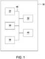
- FIG. 1is a block diagram view of an apparatus for connecting an electric vehicle to Level I or Level II power source.
- An EVSEis one such apparatus and may include an input device 32, a memory 34, a communication device 36, a processor 38, and a display 40, some or all of which can be interconnected by a data link 48.
- the EVSE 30can be a general computing device, such as a personal computer (PC), a UNIX workstation, a server, a mainframe computer, a personal digital assistant (PDA), a cellular phone, a smartphone, some combination of these or any other suitable computing device.
- the EVSE 30can be a specialized computing device made up of components specifically chosen to execute the functionality of the EVSE 30.
- the remaining componentscan include programming code, such as source code, object code or executable code, stored on a computer-readable medium that can be loaded into the memory 34 and processed by the processor 38 in order to perform the desired functions of the EVSE 30.
- the processor 38may be executed in different ways for different embodiments of the EVSE 30.
- the processor 38is a device that can read and process data such as a program instruction stored in the memory 34 or received from a source on the electric vehicle.
- Such a processor 38may be embodied by a microcontroller.
- the processor 38may be a collection of electrical circuitry components built to interpret certain electrical signals and perform certain tasks in response to those signals, or an integrated circuit.
- the memory 34may include, for example, any form or combination of volatile, non-volatile, solid state, magnetic, optical, permanent, removable, writable, rewriteable, and read-only memory.
- the memory 34may contain a number of program instructions for use with the EVSE 30.
- the instructionsmay include methods, for example, for controlling the flow of current between the electrical socket and the electric vehicle. These methods may include controlling when to allow or prohibit the flow of current, or perhaps moderate the flow of current.
- the flow of currentcan be controlled based on various factors such as when off peak rates of an electrical utility are in progress; the usage of power, for example, within a house, a building, a power grid, or a parking structure; the availability of current or if the current is constant; scheduled power outages; availability of raw materials that are used in generating electricity; the availability of alternative means of generating availability; the weather at the local charging station or outlet, which can effect means of generating electricity, such as wind mills, and solar panels and the like.
- the memorymay contain software having instructions related to diagnosing vehicle functions, such as OBD-II, battery testing, tire pressure sensor testing, emissions testing and the like.
- the softwaremay include the ability to track the status of various batteries in the vehicles, such as which batteries have been replaced, the remaining battery life of the various batteries, the warranty information about the batteries, the type of batteries used in the vehicle (mix and match) and the like. Many other embodiments may provide for further methods, some of which will be discussed herein.
- an example of the EVSE 30can communicate information to a user through the display 40 and request user input through the input device 32 by way of an interactive, menu-driven, visual display-based user interface, or graphical user interface (GUI).
- GUIgraphical user interface
- the usermay interactively input information using direct manipulation of the GUI.
- Direct manipulationcan include the use of a pointing device, such as a mouse or a stylus, to select from a variety of selectable fields, including selectable menus, drop-down menus, tabs, buttons, bullets, checkboxes, text boxes, and the like.
- various embodiments of the inventionmay incorporate any number of additional functional user interface schemes in place of this interface scheme, with or without the use of a mouse or buttons or keys, including for example, a trackball, a scroll wheel, a touch screen or a voice-activated system.
- Some options that may be selected through the input device 32may allow the user control over the charging of the electric vehicle.
- the usermay select, for example, that the batteries be charged to or at a certain level or for a certain amount of time, a certain number of charges or start and stop at a certain time or at a particular event. Further, the user may select to be notified on a separate device, like on a cellular device, smart phone, pager, fax, remote control/display, or other wired and wireless devices, that the electric vehicle or charging is in a certain state, such as complete or faulted. The user is able to set the EVSE to control and power some of the vehicle's components while plugged in.
- the EVSEmay also control setting the radio, power seats and mirrors depending on user preferences.
- other deviceslike a GPS, radar detector, and other devices that require boot or warm up periods may be powered on before the user enters the electric vehicle.
- the display 40may have a more simple implementation than previously mentioned, consisting of one or multiple indicators. Such indicators may consist of a small liquid crystal display (LCD) that can depict text or graphics.
- the LCDmay be monochrome or colored.
- Other embodimentsmay include a single or multiple light emitting diodes (LED). This implementation could work for transmitting a limited number of simple messages.
- An LEDmay emit a single color of light, or it may be able to emit a number of different colors. Each LED or color may be associated with a different message.
- Some messagesmay include that power is available to charge the electric vehicle batteries, that charging the electric vehicle batteries is in progress, that the charging is complete, and that there is a fault or problem.
- the displaymay also be used to indicate the level of charge for the batteries, the number of times the batteries have been charged and the remaining charging time or the time the batteries have been charging.
- the display 40may also be separate from the EVSE or a second remote display can be utilized.
- the second remote display(not shown) can be a remote control panel that receives the same or similar information as the display 40.
- the second remote displaycan also control the EVSE in the same or similar manner as the display 40 or the input device 32.
- FIG. 2is a schematic view of an apparatus for connecting an electric vehicle to a Level I or Level II power source according to an embodiment of the invention.
- the EVSE 30further includes a relay 42 (contactor), a voltage regulating device 44, a breaking device 46, and a switch 58, some or all of which may be connected by an electric conduit 50.
- a control circuit 56may act as a buffer between different parts of the EVSE 30.
- a socket connector 52FIG. 3
- a vehicle connector 54(explained below).
- the voltage regulating device 44may be needed to power the electronic components of the EVSE 30. Since the EVSE 30 may draw its power from the same electrical socket it uses to charge the batteries of the electric vehicle, the EVSE 30 will be receiving high voltage electricity.
- the electrical socketmay supply, for example 120 volts, 220 volts or 240 volts.
- the high voltage of the power drawn from the electrical socketcould damage some of the electronic components of the EVSE 30.
- the voltage regulator device 44such as a transformer or a voltage regulator, may be employed between to the electrical socket and the electrical components of the EVSE 30. The voltage may then be lowered to a level that is manageable to the electrical components, such as, for example, 5 volts or 12 volts. In other embodiments, the voltage regulator device 44 can increase the voltage as needed by the EVSE 30.
- While the voltage regulating device 44may regulate the voltage to parts of the EVSE 30, there are parts where electricity may flow unaltered from the electrical socket to the electric vehicle.
- An electric conduitmay run the length of the EVSE 30.
- the electric conduit 50may be of the type having a gauge and/or rating such that it may appropriately handle the range of supplied current from the electrical socket. That being, the electric conduit 50 should be able to handle at least the highest supplied current, and in turn it will also be able to handle lower levels of current.
- the electric conduit 50may be one appropriate for handling Level I and Level II charging or any level of charging.
- the electric conduit 50 suited for Level 2 chargingmay be comprised of a combination of conduits including, for example, two conduits for power supply (L1 and L2), one conduit as a neutral, and one conduit as a ground.
- the supplied currentmay be split over L1 and L2, thus aiding in supplying the proper current for Level I and Level II charging.
- the voltage regulating device 44receives power from the supplied power from the electrical socket the EVSE 30 connects to. To receive this power, the voltage regulating device 44 may be connected to, at least, L1 and/or L2.
- the electric conduit 50includes a relay 42 that may be placed to bridge segments of the electric conduit 50, allowing the EVSE 30 to start and stop the flow of current to the electric vehicle.
- the electric conduit 50is connected to a voltage regulator to step up or step down the voltage passed to the electric vehicle. Further, to aid in providing the proper current to charge the electric vehicle, it is possible to provide the relay 42 with some or all of the current provided by the electrical socket. Power supply conduits L1 and L2 may both be connected to the relay 42. Alternatively, the relay 42 may be connected to only either conduit L1 or L2.
- the relay 42may only enable the EVSE 30 to be able to provide the vehicle with Level I charging capabilities.
- the switch 58may be connected to, at least, the conduit, either L1 or L2, not already connected to the relay 42. Further, the switch 58 may be connected to the control circuit 56 that controls when the switch allows for the selective connection of the unconnected conduit, either L1 or L2, to the relay 42. The control function will be discussed below.
- a breaking device 46also called a ground device or a current monitor.
- the breaking device 46is intended to cut power along the electric conduit 50 quickly so as to avoid harming a user with a high voltage electric shock, harming the components of the EVSE or damaging the electric vehicle.
- the breaking device 46is a ground fault interrupter. If the breaking device 46 trips and cuts power, EVSE 30 has an auto-reset function to attempt to restore the power transfer to the electric vehicle.
- the auto-reset functionattempts to restore the power transfer after a determined time and/or for a determined number of tries.
- the auto-reset functionsallows for continuous charging of the vehicle should a power surge occurs while the user is asleep or away from the charging location.
- the control circuit 56may be connected to the electric conduit 50 and to the data link 48. Acting as a buffer between two portions of the EVSE 30, the control circuit passes signals from the electric conduit 50 representing the voltage on the electric conduit 50 to the processor 38. From these signals, the processor 38 reacts accordingly to control the relay 42 and the breaking device 46. Further, the processor 38, and other components, such as a voltage monitor, an oscillator, and a pulse width modulator may act accordingly to conduct a number of functions of the EVSE 30.
- the control circuit 56may also be connected to the voltage control device 44 for power, and a control pilot pin of a vehicle connector (discussed below) to pass on signals from the vehicle to the other components of the EVSE 30.
- the switch's 58In the switch's 58 initial state, it will be open, thereby causing a disconnect between the unconnected conduit, either L1 or L2, and the relay 42.
- the control circuit 56When the EVSE 30 is connected to a Level I electrical socket, the control circuit 56 would recognize that there exists a 120 volt drop between the powered conduit, either L1 or L2, and the neutral conduit of the electric conduit 50 and leave the circuit between the unconnected conduit, either L1 or L2, and the relay 42 open.
- the control circuit 56would recognize the power on the unconnected conduit and, either via a signal from the processor 38 or via logical circuitry, provide a signal to the switch 58 to close the circuit between the unconnected conduit and the relay 42. With the circuit closed, the relay 42 is connected to both power supply conduits, L1 and L2, of the electric conduit 50, and the EVSE 30 can provide the electric vehicle with Level II charging capabilities.
- the EVSEalso includes peripheral connection 51 that can add additional functionality to it, including USB, Fire-Wire, card reader, vehicle connector interface (for OBD-II, and the like connections), CD, DVD, memory, wireless communication, and additional hardware and software.
- the EVSE's softwarecan be updated via the peripheral connection 51.
- Additional hardwarecan be added to include, for example, additional processor, memory, FPGA (field programmable gate array), ASIC, pin connections, multiplexor and the other hardware to expand the functionality of the EVSE.
- FIG. 3is an elevation view of an apparatus for connecting an electric vehicle to a Level I or Level II power source according to another embodiment of the invention.
- Attached to a respective end of the electric conduit 50may be the socket connector 52 and the vehicle connector 54.
- the socket connector 52may couple with the electrical socket to allow electricity to flow to the EVSE 30.
- Any of a number of available or proprietary connectorsmay be used for the socket connector 52.
- Such available connectorsmay include a NEMA 5 plug, for example, a NEMA 5-15 plug for Level I charging, or a NEMA 14 plug, for example, a NEMA 14-50P plug for Level II charging, if appropriate for the electrical socket.
- These socket connectors 52may be interchangeable.
- the socket connectormay be of an appropriate type for Level I or Level II charging, and an adapter 60 may be used to adapt the socket connector 52 to work for the other type of charging, as discussed below.
- the vehicle connector 54Connected to the opposite end of the electric conduit 50 may be the vehicle connector 54, which also may be any number of available or proprietary connectors.
- a vehicle connector 54may be a five-pin connector including two power pins, a ground pin, a control pilot pin, and a proximity sensor pin as specified in the SAE standard J1772 and designed by Yazaki of North America.
- the EVSE 30includes a housing 62.
- the housing 62encases a number of the components of the EVSE 30, for example, all the components previously mentioned except for portions of the electric conduit 50, the socket connector 52 and the vehicle connector 54.
- a bracketmay be attached to the housing 62 to mount the housing 62 on a vertical surface such as a wall or post.
- the housing 62 or bracketmay further include a hook to hang the power conduit 50.
- the power conduitmay be retractable into the housing 62.
- the EVSE 30may be available for both indoor and outdoor applications. Proper weather proofing may be part of the housing to protect the components from damage and the users from injury. Some outdoor installations of the EVSE 30 may include burial in the ground, being attached to a post, or integrated into a pedestal.
- FIG. 4illustrates adapters 60A and 60B for connecting an apparatus that connects to a Level I or Level II power source.
- the socket connector 52is, for example, a NEMA type 5 plug suitable for Level I charging is at the end of the electric conduit 50, and it is desired to plug the EVSE 30 into a Level II socket
- the adapter 60Ais configured to accept the prongs of the socket connector 52 (with NEMA type 5 plug) and has prongs configured to be inserted into a Level II socket.
- the adapter 60Bis configured to accept the prongs of the socket connector 52 (with NEMA type 14 plug) and has prongs configured to be inserted into a Level I socket.
- An example of an adapter 60B that would allow for connecting the socket connector 52 configured to connect to a Level II socket to connect to a Level I socketis the Marinco 50A to 15A RV Pigtail Adapter 150SPPRV.
- the EVSE 30can be coupled to a communication network.
- the communication networkallows for communication between the EVSE 30 and a remote device.
- the EVSE 30can be coupled to the communication network by way of the communication device 36 which in various embodiments can incorporate any combination of devices-as well as any associated software or firmware-configured to couple processor-based systems.
- Such communication devices 36may include modems, network interface cards, serial buses, parallel buses, LAN or WAN interfaces, wired, wireless or optical interfaces, and the like, along with any associated transmission protocols, as may be desired or required by the design.
- the communication networklinks the communication device 36 of the EVSE 30 with the remote device.
- Various embodiments of the communication networkmay include any viable combination of devices and systems capable of linking computer-based systems, such as USB; Bluetooth; WiFi; ZigBee; power line communication (PLC); home area network (HAN); Silver Spring network; stable election protocol (SEP); the Internet; TCP/IP; an intranet or extranet; a local area network (LAN); a wide area network (WAN); a direct cable connection; a private network; a public network; an Ethernet-based system; a token ring; a value-added network; a telephony-based system, including, for example, T1 or E1 devices; a cellular telephony system, for example, GPRS or GSM; an Asynchronous Transfer Mode (ATM) network; a wired system; a wireless system; an optical system; a combination of any number of distributed processing networks or systems or the like.
- ATMAsynchronous Transfer Mode
- the remote devicemay be a common remote device, such as a electronic control unit of a vehicle, an example of which often used in vehicles for receiving diagnostic signals such an OBD-II signals.
- the remote devicemay also be a proprietary remote device, such as one developed for use with a specific brand of engine or specific model of engine. Further embodiments may encompass the remote device being a data receiver for a tire pressure management system. In either of these cases, the communication device 36 may be able to connect with a dealer, manufacturer, service department, government entity such as a state inspection office, etc. and report the findings transmitted from the remote device.
- the remote devicemay be a wireless device with a display that gives the user information about the status of the electric vehicle connected to the EVSE 30.
- the remote devicemay be such that it is easily placed within a room in a building, or even attached to a key like a key chain.
- the information delivered to the usermay include charge status of the vehicle, diagnostic messages, tire pressure management system messages, and other vehicle related information.
- the EVSE 30may also act as a remote control allowing the user to control function of the car, like power, air conditioning and heat, radio settings, power seat and mirror settings, etc.
- the EVSE 30may also have internet access or similar communication access to remote server in order to obtain information such as emails, weather report, web pages, stock information, diagnostic databases and the other information.
- the communication device 36may also be able to communicate with the local utility company. This may allow for the utility company to know that the vehicle in connected and to charge the vehicle at a certain time of the day, such as during off-peak hours, if requested by the user.
- One embodiment to implement this featureis through the remote device, where the remote device encompasses a smart meter or a computerized utility meter.
- the EVSE 30may communicate with the smart meter to determine when the EVSE 30 should charge the vehicle depending on certain parameters. If it is a goal to reduce energy costs, the smart meter may determine at what time of the day the rate for electricity is lowest, and during that time, tell the EVSE 30 to charge the vehicle.
- the EVSE 30may also communicate with the smart meter to indicate when the vehicle is charging and how much charging is required. With this information the smart meter may be able to manage the power consumption of the rest of a house to keep overall power consumption at or below a desired level.
- the EVSE 30may allow for multiple power conduits 50, each with its own vehicle connector 54.
- the EVSE 30may charge the vehicles simultaneously or switch from one vehicle to another after the first vehicle has completed recharging.
- Theremay also be an adapter that allows the socket connector to connect to low voltage sockets, such as ones that provide 120 volts or less, as discussed herein.
- the EVSE 30can connect to alternative power sources that use renewable energy to charge the vehicle. Such sources may include solar panels and wind turbines, for example. If the alternative power sources alone are insufficient, then they may be supplemented by an electrical socket connected to a utility company source.
- the EVSEmay potentially perform a variety of other functions in addition to its primary purpose of charging the electric vehicle. Multiple embodiments may also include any number of functions that may be considered secondary purposes of the EVSE. A few examples of these functions may include conducting battery tests and reporting the state of the batteries and the number of times the batteries have been charged. The EVSE may also conduct vehicle diagnostics, execute a tire pressure management system, run an emissions analysis, etc.
Landscapes
- Engineering & Computer Science (AREA)
- Power Engineering (AREA)
- Transportation (AREA)
- Mechanical Engineering (AREA)
- Life Sciences & Earth Sciences (AREA)
- Sustainable Development (AREA)
- Sustainable Energy (AREA)
- Electric Propulsion And Braking For Vehicles (AREA)
- Charge And Discharge Circuits For Batteries Or The Like (AREA)
- Protection Of Static Devices (AREA)
Description
- The present invention relates generally to providing power to recharge the batteries of battery electric vehicles and plug-in hybrid electric vehicles. More particularly, the present invention relates to electric vehicle power supply equipment to deliver Level I charging (up to 15 amps or 20 amps and 120 volts) and/or Level II charging (up to 80 amps and 240 volts) from an electrical socket.
- Vehicles powered either fully or partially by batteries must at some point recharge their batteries. Particularly in the case of battery electric vehicles, the lack of an alternative power source, like one that a plug-in hybrid electric vehicle would have, causes the batteries to deplete faster and have a more limited range. Plug-in electric hybrids are generally less taxing on the batteries and built-in regenerative systems may suffice to recharge the batteries enough to go longer without having to plug-in the vehicle to recharge it. However, the driver will dictate the need for recharging an electric vehicle through the extent of use, driving conditions, and driving style. High mileage, stop-and-go traffic, and quick accelerations are all things that the driver may subject an electric vehicle to, and all will deplete the batteries faster than under ideal conditions.
- The standard American electrical socket provides 120 volts A/C (alternating current). The common availability of the 120 volt A/C electricity supply makes it a convenient choice for the power supply for recharging the batteries of electric vehicles. Many garages, carports, or outdoor parking areas may currently have 120 volt A/C electrical outlets, or may easily have one added, so that the power source may be connected to the electric vehicle for Level I charging.
- However, the 120 volt A/C electricity supply is often insufficient to recharge the batteries of an electric vehicle in a period of time to allow for convenient use of the electric vehicle. A full recharge may not even be completed overnight and partial recharges often take too much time to be practical. Providing a higher voltage electricity supply can greatly reduce the amount of time needed to recharge an electric vehicle. Such high voltage sources are available in homes and other locations, and may be used for Level II charging.
- It is desirable to provide a convenient way of connecting the Level I or Level II electricity source to an electric vehicle to recharge the batteries thereby making recharging quicker and using an electric vehicle more practical. It is also desirable to provide a convenient way to plug the electric vehicle supply equipment to either a Level I or Level II electrical supply source using plugs and receptacles designed to meet National Electrical Manufacturers Association (NEMA) standards, and with minimal duplication of components. This will reduce the cost of the product, installation, service repair, relocation and greatly simplifying the local electrical permitting process. This will also make the electric vehicle more practical, acceptable and provide a lower cost of ownership for the vehicle consumer.
WO 2009/051014 A1 describes a hybrid vehicle comprising an accumulation device for outputting electric power to drive the vehicle. Motor generators and inventers act as power receiving units for receiving electric power from a power source outside of the vehicle to charge the accumulation device.US 2008/002313 A1 describes resettable circuit interrupting devices having self-test and non-resettable or limited resettable power interrupting systems.- At least in view of the above, it would be desirable to provide a system for connecting a high voltage electricity source to an electric vehicle to recharge its batteries. The foregoing needs are met, to a great extent, by certain embodiments of the present invention.
- According to a first aspect of the invention there is provided an apparatus according to
claim 1. - According to a second aspect of the present invention there is provided a method according to claim 13.
- Preferred embodiments are defined in dependent claims.
- [DELETED]
- [DELETED]
- Before explaining at least one embodiment of the invention in detail, it is to be understood that the invention is not limited in its application to the details of construction and to the arrangements of the components set forth in the following description or illustrated in the drawings. The invention is capable of embodiments in addition to those described and of being practiced and carried out in various ways. Also, it is to be understood that the phraseology and terminology employed herein, as well as the abstract, are for the purpose of description and should not be regarded as limiting.
- As such, those skilled in the art will appreciate that the conception upon which this disclosure is based may readily be utilized as a basis for the designing of other structures, methods and systems for carrying out the several purposes of the present invention. It is important, therefore, that the claims be regarded as including such equivalent constructions insofar as they do not depart from the scope of the present invention.
FIG. 1 is a block diagram view of an apparatus for connecting an electric vehicle to Level I or Level II power source according to an embodiment of the invention.FIG. 2 is a schematic view of an apparatus for connecting an electric vehicle to a Level I or Level II power source according to another embodiment of the invention.FIG. 3 is an elevation view of an apparatus for connecting an electric vehicle to a Level I or Level II power source according to another embodiment of the invention.FIG. 4 illustrates adapters for connecting an apparatus that connects to a Level I or Level II power source according to another embodiment of the invention.- In this respect, before explaining at least one embodiment of the invention in detail, it is to be understood that the invention is not limited in its application to the details of construction and to the arrangements of the components set forth in the following description or illustrated in the drawings. The invention is capable of embodiments in addition to those described and of being practiced and carried out in various ways. Also, it is to be understood that the phraseology and terminology employed herein, as well as the abstract, are for the purpose of description and should not be regarded as limiting.
FIG. 1 is a block diagram view of an apparatus for connecting an electric vehicle to Level I or Level II power source according to an embodiment of the invention.FIG. 2 is a schematic view of an apparatus for connecting an electric vehicle to a Level I or Level II power source according to another embodiment of the invention.FIG. 3 is an elevation view of an apparatus for connecting an electric vehicle to a Level I or Level II power source according to another embodiment of the invention.FIG. 4 illustrates adapters for connecting an apparatus that connects to a Level I or Level II power source according to another embodiment of the invention.- An embodiment of the present inventive system for connecting an electric vehicle, such as a battery electric vehicle (BEV) or a plug-in hybrid electric vehicle (PHEV), to a Level I or II power source includes an apparatus, such as an electric vehicle supply equipment (EVSE) for connecting the electric vehicle to a power source. The EVSE may be employed to make a circuit connection to allow power from an electrical socket, like a wall socket, to flow to a charging circuit within the electric vehicle. The wall socket may be a standard outlet found in a residential garage or a socket at a powering station outside the residential garage. The power station may be positioned, for example, at a parking garage, at a public parking space, at a rest stop, a conventional gas station, or a powering station (similar to a gas station, but has power stations instead of gas pumps). Further, the EVSE may be constructed to at least meet industry standards, such as SAE J1772, UL 2594, and NEC Article 625. The SAE J2836 vehicle communication standard may also be considered in constructing the EVSE.
- The EVSE has a socket connector at a first end to couple the EVSE to the electrical socket, such as a wall socket, and a vehicle connector at a second end to couple the EVSE to the electric vehicle. Once coupled,to both the wall socket and the vehicle, the EVSE may allow passage of electrical current from the wall socket to the electric vehicle, thus recharging the electric vehicles' batteries. This embodiment allows for the use of standard electrical outlets instead of hardwiring the EVSE directly to a power source.
- Level I and Level II sockets are different in configurations. The EVSE may be constructed and/or provided with adapters to make the EVSE compatible with both a Level I and II socket. This may be accomplished through a combination of internal hardware and/or electrical components, external wiring components, and plug components and/or adapters.
- In addition, the EVSE may analyze signals and/or data received from the electric vehicle. Analyzing the signals and/or data may involve checking the electric vehicle for specific conditions. While analyzing, the EVSE may determine when to allow and when to prohibit the flow of current between the socket and the electric vehicle.
- The invention will now be described with reference to the drawing figures, in which like reference numerals refer to like parts throughout.
FIG. 1 is a block diagram view of an apparatus for connecting an electric vehicle to Level I or Level II power source. An EVSE is one such apparatus and may include aninput device 32, amemory 34, acommunication device 36, aprocessor 38, and adisplay 40, some or all of which can be interconnected by adata link 48. TheEVSE 30 can be a general computing device, such as a personal computer (PC), a UNIX workstation, a server, a mainframe computer, a personal digital assistant (PDA), a cellular phone, a smartphone, some combination of these or any other suitable computing device. Alternatively, theEVSE 30 can be a specialized computing device made up of components specifically chosen to execute the functionality of theEVSE 30. The remaining components can include programming code, such as source code, object code or executable code, stored on a computer-readable medium that can be loaded into thememory 34 and processed by theprocessor 38 in order to perform the desired functions of theEVSE 30.- The
processor 38 may be executed in different ways for different embodiments of theEVSE 30. One embodiment is that theprocessor 38 is a device that can read and process data such as a program instruction stored in thememory 34 or received from a source on the electric vehicle. Such aprocessor 38 may be embodied by a microcontroller. On the other hand, theprocessor 38 may be a collection of electrical circuitry components built to interpret certain electrical signals and perform certain tasks in response to those signals, or an integrated circuit. - The
memory 34 may include, for example, any form or combination of volatile, non-volatile, solid state, magnetic, optical, permanent, removable, writable, rewriteable, and read-only memory. Thememory 34 may contain a number of program instructions for use with theEVSE 30. The instructions may include methods, for example, for controlling the flow of current between the electrical socket and the electric vehicle. These methods may include controlling when to allow or prohibit the flow of current, or perhaps moderate the flow of current. The flow of current can be controlled based on various factors such as when off peak rates of an electrical utility are in progress; the usage of power, for example, within a house, a building, a power grid, or a parking structure; the availability of current or if the current is constant; scheduled power outages; availability of raw materials that are used in generating electricity; the availability of alternative means of generating availability; the weather at the local charging station or outlet, which can effect means of generating electricity, such as wind mills, and solar panels and the like. - Further, the memory may contain software having instructions related to diagnosing vehicle functions, such as OBD-II, battery testing, tire pressure sensor testing, emissions testing and the like. Further, the software may include the ability to track the status of various batteries in the vehicles, such as which batteries have been replaced, the remaining battery life of the various batteries, the warranty information about the batteries, the type of batteries used in the vehicle (mix and match) and the like. Many other embodiments may provide for further methods, some of which will be discussed herein.
- Additionally, an example of the
EVSE 30 can communicate information to a user through thedisplay 40 and request user input through theinput device 32 by way of an interactive, menu-driven, visual display-based user interface, or graphical user interface (GUI). The user may interactively input information using direct manipulation of the GUI. Direct manipulation can include the use of a pointing device, such as a mouse or a stylus, to select from a variety of selectable fields, including selectable menus, drop-down menus, tabs, buttons, bullets, checkboxes, text boxes, and the like. Nevertheless, various embodiments of the invention may incorporate any number of additional functional user interface schemes in place of this interface scheme, with or without the use of a mouse or buttons or keys, including for example, a trackball, a scroll wheel, a touch screen or a voice-activated system. - Some options that may be selected through the
input device 32 may allow the user control over the charging of the electric vehicle. The user may select, for example, that the batteries be charged to or at a certain level or for a certain amount of time, a certain number of charges or start and stop at a certain time or at a particular event. Further, the user may select to be notified on a separate device, like on a cellular device, smart phone, pager, fax, remote control/display, or other wired and wireless devices, that the electric vehicle or charging is in a certain state, such as complete or faulted. The user is able to set the EVSE to control and power some of the vehicle's components while plugged in. For example, during different seasons the user may desire to heat or cool the vehicle as he gets ready for work in the morning so that the vehicle is comfortable when he gets in it. The EVSE may also control setting the radio, power seats and mirrors depending on user preferences. Through the use of the EVSE, other devices like a GPS, radar detector, and other devices that require boot or warm up periods may be powered on before the user enters the electric vehicle. - The
display 40 may have a more simple implementation than previously mentioned, consisting of one or multiple indicators. Such indicators may consist of a small liquid crystal display (LCD) that can depict text or graphics. The LCD may be monochrome or colored. Other embodiments may include a single or multiple light emitting diodes (LED). This implementation could work for transmitting a limited number of simple messages. An LED may emit a single color of light, or it may be able to emit a number of different colors. Each LED or color may be associated with a different message. Some messages may include that power is available to charge the electric vehicle batteries, that charging the electric vehicle batteries is in progress, that the charging is complete, and that there is a fault or problem. The display may also be used to indicate the level of charge for the batteries, the number of times the batteries have been charged and the remaining charging time or the time the batteries have been charging. - The
display 40 may also be separate from the EVSE or a second remote display can be utilized. The second remote display (not shown) can be a remote control panel that receives the same or similar information as thedisplay 40. The second remote display can also control the EVSE in the same or similar manner as thedisplay 40 or theinput device 32. FIG. 2 is a schematic view of an apparatus for connecting an electric vehicle to a Level I or Level II power source according to an embodiment of the invention. TheEVSE 30 further includes a relay 42 (contactor), avoltage regulating device 44, a breakingdevice 46, and aswitch 58, some or all of which may be connected by anelectric conduit 50. Acontrol circuit 56 may act as a buffer between different parts of theEVSE 30. At one end of the EVSE is a socket connector 52 (FIG. 3 ) and at the other end is a vehicle connector 54 (explained below).- The
voltage regulating device 44 may be needed to power the electronic components of theEVSE 30. Since theEVSE 30 may draw its power from the same electrical socket it uses to charge the batteries of the electric vehicle, theEVSE 30 will be receiving high voltage electricity. The electrical socket may supply, for example 120 volts, 220 volts or 240 volts. The high voltage of the power drawn from the electrical socket could damage some of the electronic components of theEVSE 30. Thus, thevoltage regulator device 44, such as a transformer or a voltage regulator, may be employed between to the electrical socket and the electrical components of theEVSE 30. The voltage may then be lowered to a level that is manageable to the electrical components, such as, for example, 5 volts or 12 volts. In other embodiments, thevoltage regulator device 44 can increase the voltage as needed by theEVSE 30. - While the
voltage regulating device 44 may regulate the voltage to parts of theEVSE 30, there are parts where electricity may flow unaltered from the electrical socket to the electric vehicle. An electric conduit may run the length of theEVSE 30. - In one embodiment of the invention, the
electric conduit 50 may be of the type having a gauge and/or rating such that it may appropriately handle the range of supplied current from the electrical socket. That being, theelectric conduit 50 should be able to handle at least the highest supplied current, and in turn it will also be able to handle lower levels of current. Theelectric conduit 50 may be one appropriate for handling Level I and Level II charging or any level of charging. Theelectric conduit 50 suited forLevel 2 charging may be comprised of a combination of conduits including, for example, two conduits for power supply (L1 and L2), one conduit as a neutral, and one conduit as a ground. The supplied current may be split over L1 and L2, thus aiding in supplying the proper current for Level I and Level II charging. - In connecting the electric conduit to the internal components of the
EVSE 30, it may be convenient to connect some or all of the combination of conduits that make up theelectric conduit 50 to the different internal components. For example, thevoltage regulating device 44, as discussed above, receives power from the supplied power from the electrical socket theEVSE 30 connects to. To receive this power, thevoltage regulating device 44 may be connected to, at least, L1 and/or L2. - The
electric conduit 50 includes arelay 42 that may be placed to bridge segments of theelectric conduit 50, allowing theEVSE 30 to start and stop the flow of current to the electric vehicle. Theelectric conduit 50 is connected to a voltage regulator to step up or step down the voltage passed to the electric vehicle. Further, to aid in providing the proper current to charge the electric vehicle, it is possible to provide therelay 42 with some or all of the current provided by the electrical socket. Power supply conduits L1 and L2 may both be connected to therelay 42. Alternatively, therelay 42 may be connected to only either conduit L1 or L2. - In an alternative embodiment, it may be that when only connected to conduit L1 or L2, the
relay 42 may only enable the EVSE 30 to be able to provide the vehicle with Level I charging capabilities. Thus, to enable the EVSE 30 to provide Level II charging capabilities, as well as Level I charging, it maybe a possible to provide aswitch 58 that will allow the EVSE 30 to selectively connect the unconnected conduit, either L1 or L2, to therelay 42. In one embodiment, theswitch 58 may be connected to, at least, the conduit, either L1 or L2, not already connected to therelay 42. Further, theswitch 58 may be connected to thecontrol circuit 56 that controls when the switch allows for the selective connection of the unconnected conduit, either L1 or L2, to therelay 42. The control function will be discussed below. - Also connected to the
electric conduit 50 is a breaking device 46 (also called a ground device or a current monitor). The breakingdevice 46 is intended to cut power along theelectric conduit 50 quickly so as to avoid harming a user with a high voltage electric shock, harming the components of the EVSE or damaging the electric vehicle. The breakingdevice 46 is a ground fault interrupter. If thebreaking device 46 trips and cuts power,EVSE 30 has an auto-reset function to attempt to restore the power transfer to the electric vehicle. The auto-reset function attempts to restore the power transfer after a determined time and/or for a determined number of tries. The auto-reset functions allows for continuous charging of the vehicle should a power surge occurs while the user is asleep or away from the charging location. - The
control circuit 56 may be connected to theelectric conduit 50 and to thedata link 48. Acting as a buffer between two portions of theEVSE 30, the control circuit passes signals from theelectric conduit 50 representing the voltage on theelectric conduit 50 to theprocessor 38. From these signals, theprocessor 38 reacts accordingly to control therelay 42 and thebreaking device 46. Further, theprocessor 38, and other components, such as a voltage monitor, an oscillator, and a pulse width modulator may act accordingly to conduct a number of functions of theEVSE 30. Thecontrol circuit 56 may also be connected to thevoltage control device 44 for power, and a control pilot pin of a vehicle connector (discussed below) to pass on signals from the vehicle to the other components of theEVSE 30. - In the switch's 58 initial state, it will be open, thereby causing a disconnect between the unconnected conduit, either L1 or L2, and the
relay 42. When theEVSE 30 is connected to a Level I electrical socket, thecontrol circuit 56 would recognize that there exists a 120 volt drop between the powered conduit, either L1 or L2, and the neutral conduit of theelectric conduit 50 and leave the circuit between the unconnected conduit, either L1 or L2, and therelay 42 open. Alternatively, when theEVSE 30 is plugged into a Level II electrical socket, then thecontrol circuit 56 would recognize the power on the unconnected conduit and, either via a signal from theprocessor 38 or via logical circuitry, provide a signal to theswitch 58 to close the circuit between the unconnected conduit and therelay 42. With the circuit closed, therelay 42 is connected to both power supply conduits, L1 and L2, of theelectric conduit 50, and theEVSE 30 can provide the electric vehicle with Level II charging capabilities. - The EVSE also includes
peripheral connection 51 that can add additional functionality to it, including USB, Fire-Wire, card reader, vehicle connector interface (for OBD-II, and the like connections), CD, DVD, memory, wireless communication, and additional hardware and software. The EVSE's software can be updated via theperipheral connection 51. Additional hardware can be added to include, for example, additional processor, memory, FPGA (field programmable gate array), ASIC, pin connections, multiplexor and the other hardware to expand the functionality of the EVSE. FIG. 3 is an elevation view of an apparatus for connecting an electric vehicle to a Level I or Level II power source according to another embodiment of the invention. Attached to a respective end of theelectric conduit 50 may be thesocket connector 52 and thevehicle connector 54. Thesocket connector 52 may couple with the electrical socket to allow electricity to flow to theEVSE 30. Any of a number of available or proprietary connectors may be used for thesocket connector 52. Such available connectors may include a NEMA 5 plug, for example, a NEMA 5-15 plug for Level I charging, or a NEMA 14 plug, for example, a NEMA 14-50P plug for Level II charging, if appropriate for the electrical socket. Thesesocket connectors 52 may be interchangeable. Alternatively, the socket connector may be of an appropriate type for Level I or Level II charging, and an adapter 60 may be used to adapt thesocket connector 52 to work for the other type of charging, as discussed below. Connected to the opposite end of theelectric conduit 50 may be thevehicle connector 54, which also may be any number of available or proprietary connectors. One such example of avehicle connector 54 may be a five-pin connector including two power pins, a ground pin, a control pilot pin, and a proximity sensor pin as specified in the SAE standard J1772 and designed by Yazaki of North America.- The
EVSE 30 includes ahousing 62. Thehousing 62 encases a number of the components of theEVSE 30, for example, all the components previously mentioned except for portions of theelectric conduit 50, thesocket connector 52 and thevehicle connector 54. A bracket may be attached to thehousing 62 to mount thehousing 62 on a vertical surface such as a wall or post. Thehousing 62 or bracket may further include a hook to hang thepower conduit 50. Alternatively, the power conduit may be retractable into thehousing 62. - The
EVSE 30 may be available for both indoor and outdoor applications. Proper weather proofing may be part of the housing to protect the components from damage and the users from injury. Some outdoor installations of theEVSE 30 may include burial in the ground, being attached to a post, or integrated into a pedestal. FIG. 4 illustratesadapters socket connector 52 is, for example, a NEMA type 5 plug suitable for Level I charging is at the end of theelectric conduit 50, and it is desired to plug theEVSE 30 into a Level II socket, then theadapter 60A is configured to accept the prongs of the socket connector 52 (with NEMA type 5 plug) and has prongs configured to be inserted into a Level II socket. Alternatively, if thesocket connector 52 is, for example, a NEMA type 14 plug suitable for Level II charging is at the end of theelectric conduit 50, and it is desired to plug theEVSE 30 into a Level I socket, then theadapter 60B is configured to accept the prongs of the socket connector 52 (with NEMA type 14 plug) and has prongs configured to be inserted into a Level I socket. An example of anadapter 60B that would allow for connecting thesocket connector 52 configured to connect to a Level II socket to connect to a Level I socket is the Marinco 50A to 15A RV Pigtail Adapter 150SPPRV.- Referring back to
FIG. 1 , in various embodiments, theEVSE 30 can be coupled to a communication network. The communication network allows for communication between the EVSE 30 and a remote device. TheEVSE 30 can be coupled to the communication network by way of thecommunication device 36 which in various embodiments can incorporate any combination of devices-as well as any associated software or firmware-configured to couple processor-based systems.Such communication devices 36 may include modems, network interface cards, serial buses, parallel buses, LAN or WAN interfaces, wired, wireless or optical interfaces, and the like, along with any associated transmission protocols, as may be desired or required by the design. - The communication network links the
communication device 36 of theEVSE 30 with the remote device. Various embodiments of the communication network may include any viable combination of devices and systems capable of linking computer-based systems, such as USB; Bluetooth; WiFi; ZigBee; power line communication (PLC); home area network (HAN); Silver Spring network; stable election protocol (SEP); the Internet; TCP/IP; an intranet or extranet; a local area network (LAN); a wide area network (WAN); a direct cable connection; a private network; a public network; an Ethernet-based system; a token ring; a value-added network; a telephony-based system, including, for example, T1 or E1 devices; a cellular telephony system, for example, GPRS or GSM; an Asynchronous Transfer Mode (ATM) network; a wired system; a wireless system; an optical system; a combination of any number of distributed processing networks or systems or the like. - The remote device may be a common remote device, such as a electronic control unit of a vehicle, an example of which often used in vehicles for receiving diagnostic signals such an OBD-II signals. The remote device may also be a proprietary remote device, such as one developed for use with a specific brand of engine or specific model of engine. Further embodiments may encompass the remote device being a data receiver for a tire pressure management system. In either of these cases, the
communication device 36 may be able to connect with a dealer, manufacturer, service department, government entity such as a state inspection office, etc. and report the findings transmitted from the remote device. - Moreover, the remote device may be a wireless device with a display that gives the user information about the status of the electric vehicle connected to the
EVSE 30. The remote device may be such that it is easily placed within a room in a building, or even attached to a key like a key chain. The information delivered to the user may include charge status of the vehicle, diagnostic messages, tire pressure management system messages, and other vehicle related information. - The
EVSE 30 may also act as a remote control allowing the user to control function of the car, like power, air conditioning and heat, radio settings, power seat and mirror settings, etc. TheEVSE 30 may also have internet access or similar communication access to remote server in order to obtain information such as emails, weather report, web pages, stock information, diagnostic databases and the other information. - The
communication device 36 may also be able to communicate with the local utility company. This may allow for the utility company to know that the vehicle in connected and to charge the vehicle at a certain time of the day, such as during off-peak hours, if requested by the user. One embodiment to implement this feature is through the remote device, where the remote device encompasses a smart meter or a computerized utility meter. TheEVSE 30 may communicate with the smart meter to determine when theEVSE 30 should charge the vehicle depending on certain parameters. If it is a goal to reduce energy costs, the smart meter may determine at what time of the day the rate for electricity is lowest, and during that time, tell the EVSE 30 to charge the vehicle. TheEVSE 30 may also communicate with the smart meter to indicate when the vehicle is charging and how much charging is required. With this information the smart meter may be able to manage the power consumption of the rest of a house to keep overall power consumption at or below a desired level. - Other embodiments of the
EVSE 30 may allow formultiple power conduits 50, each with itsown vehicle connector 54. TheEVSE 30 may charge the vehicles simultaneously or switch from one vehicle to another after the first vehicle has completed recharging. There may also be an adapter that allows the socket connector to connect to low voltage sockets, such as ones that provide 120 volts or less, as discussed herein. In other embodiments, theEVSE 30 can connect to alternative power sources that use renewable energy to charge the vehicle. Such sources may include solar panels and wind turbines, for example. If the alternative power sources alone are insufficient, then they may be supplemented by an electrical socket connected to a utility company source. - As stated above, the EVSE may potentially perform a variety of other functions in addition to its primary purpose of charging the electric vehicle. Multiple embodiments may also include any number of functions that may be considered secondary purposes of the EVSE. A few examples of these functions may include conducting battery tests and reporting the state of the batteries and the number of times the batteries have been charged. The EVSE may also conduct vehicle diagnostics, execute a tire pressure management system, run an emissions analysis, etc.
Claims (12)
- Apparatus (30) for connecting an electric vehicle to an electrical socket, comprising:a socket connector (52) configured to couple with the electrical socket to receive 220 to 240 volts alternating current;a housing (62);a power conduit (50) connected to the socket connector (52) and configured to convey a voltage from the electrical socket, the power conduit (50) extending from the socket connector (52) to the housing (62), through the housing (62), and out the housing (62);a power control device comprising a relay (42) to bridge portions of the power conduit (50) arranged in the housing (62) and connected to the power conduit (50);a current monitor comprising a ground fault interrupter (46) arranged in the housing (62) and connected to the power conduit (50);a control circuit (56) arranged in the housing (62) and connected to the power conduit (50) and configured to generate signals corresponding to the voltage along the power conduit;a vehicle connecter (54) connected to the power conduit (50) configured to connect to the electric vehicle to deliver the 220 to 240 volts alternating current to the vehicle, the vehicle connector (54) comprising a SAE J1722 connector;a processor (38) arranged in the housing (62) and connected to the control circuit (56) and configured to receive the signals corresponding to the voltage along the power conduit from the control circuit (56) and send signals to the control circuit (56), wherein the processor (38) is configured to react according to the signals received from the control circuit (56) to control the relay (42) and the ground fault interrupter (46) and wherein the processor (38) is further configured to control components of the electric vehicle including heating or cooling of the vehicle;an auto-reset function configured to, if the ground fault interrupter (46) interrupts power transfer to the electric vehicle, restore power transfer to the electric vehicle after an interruption of power transfer for a predetermined period of time or for a predetermined number of tries; anda voltage regulator (44) configured to step up or step down the voltage to provide regulated voltage to the processor (38).
- The apparatus of claim 1, wherein the current monitor is disposed between the power control device and the vehicle connector (54).
- The apparatus of claim 1, wherein the control circuit is configured to isolate the processor from the voltage along the power conduit.
- The apparatus of claim 1, wherein the control circuit (56) is connected to the power conduit (50) before the power control device and after the current monitor.
- The apparatus of claim 1, wherein the control circuit (56) is connected to the vehicle connector (54).
- The apparatus of claim 1, wherein the power conduit (50) connects to the power control device and the voltage regulator (44), wherein the power control device is connected to the vehicle connector (54) such that the power control device controls the flow or magnitude of the voltage to the vehicle connector (54), and the voltage regulator (44) is connected to the control circuit (56) and the processor (38) such that the voltage regulator (44) controls the flow or magnitude of voltage to the control circuit (56) and the processor (38).
- The apparatus of claim 1, comprising:a voltage monitor connected to the processor (38);a pulse width modulator connected to the processor (38); anda display (40) connected to the processor (38).
- The apparatus of claim 6, wherein the display (40) is selected from one of an LED display and an LCD display.
- The apparatus of claim 1, wherein the housing (62) is configured to be mounted on a wall or post.
- The apparatus of claim 1, comprising a peripheral connection (51) to connect to at least one of a USB connector, Fire-Wire connector, card reader, OBD-II vehicle connector interface, and a wireless communication device.
- The apparatus of claim 1, comprising an input device (32) configured to receive input from a user.
- A method of charging an electrical vehicle, comprising:receiving a 220 to 240 volts alternating current from a power source;conducting the 220 to 240 volts alternating current from the power source to the electrical vehicle via a power conduit (50);controlling the voltage flowing on the power conduit (50) with a switching relay (42);isolating a processor (38) from the voltage on the power conduit (50) with a control circuit (56);cutting power to the electrical vehicle with a ground fault interrupter (46);passing signals from the power conduit (50) representing the voltage on the power conduit (50) to the processor (38) via the control circuit (56), wherein the processor is configured to react according to the signals passed from the power conduit (50) to control the relay (42) and the ground fault interrupter (46);restoring, with an auto-reset function, power transfer to the electric vehicle after an interruption of power transfer for a predetermined period of time or for a predetermined number of tries, if the ground fault interrupter (46) interrupts power transfer to the electric vehicle;controlling, with the processor (38), components of the electric vehicle including heating or cooling of the vehicle;displaying information to a user with a display (40);receiving input from a user with an input device (32); andproviding a peripheral connection (51) to connect to at least one of a USB connector, Fire-Wire connector, card reader, OBD-II vehicle connector interface, and a wireless communication device.
Applications Claiming Priority (4)
| Application Number | Priority Date | Filing Date | Title |
|---|---|---|---|
| US22910409P | 2009-07-28 | 2009-07-28 | |
| US12/646,276US8710796B2 (en) | 2009-07-28 | 2009-12-23 | Electric vehicle supply equipment having a socket and a method of charging an electric vehicle |
| US12/772,519US8860366B2 (en) | 2009-07-28 | 2010-05-03 | Plug-in electric vehicle supply equipment |
| EP10171122.4AEP2281711B1 (en) | 2009-07-28 | 2010-07-28 | Plug-in electric vehicle supply equipment |
Related Parent Applications (2)
| Application Number | Title | Priority Date | Filing Date |
|---|---|---|---|
| EP10171122.4ADivisionEP2281711B1 (en) | 2009-07-28 | 2010-07-28 | Plug-in electric vehicle supply equipment |
| EP10171122.4ADivision-IntoEP2281711B1 (en) | 2009-07-28 | 2010-07-28 | Plug-in electric vehicle supply equipment |
Publications (3)
| Publication Number | Publication Date |
|---|---|
| EP3241703A2 EP3241703A2 (en) | 2017-11-08 |
| EP3241703A3 EP3241703A3 (en) | 2017-11-15 |
| EP3241703B1true EP3241703B1 (en) | 2019-11-06 |
Family
ID=43086097
Family Applications (2)
| Application Number | Title | Priority Date | Filing Date |
|---|---|---|---|
| EP10171122.4AActiveEP2281711B1 (en) | 2009-07-28 | 2010-07-28 | Plug-in electric vehicle supply equipment |
| EP17173126.8AActiveEP3241703B1 (en) | 2009-07-28 | 2010-07-28 | Electric vehicle supply equipment having a socket and a method of charging an electric vehicle |
Family Applications Before (1)
| Application Number | Title | Priority Date | Filing Date |
|---|---|---|---|
| EP10171122.4AActiveEP2281711B1 (en) | 2009-07-28 | 2010-07-28 | Plug-in electric vehicle supply equipment |
Country Status (1)
| Country | Link |
|---|---|
| EP (2) | EP2281711B1 (en) |
Families Citing this family (9)
| Publication number | Priority date | Publication date | Assignee | Title |
|---|---|---|---|---|
| US8710796B2 (en) | 2009-07-28 | 2014-04-29 | Bosch Automotive Service Solutions Llc | Electric vehicle supply equipment having a socket and a method of charging an electric vehicle |
| DE102011007839A1 (en)* | 2011-04-21 | 2012-10-25 | Bayerische Motoren Werke Aktiengesellschaft | Vehicle charger |
| FR2974686B1 (en)* | 2011-04-27 | 2013-06-14 | Peugeot Citroen Automobiles Sa | SECURE LOAD SYSTEM OF AN ELECTRIC OR HYBRID VEHICLE |
| US8624719B2 (en) | 2011-06-03 | 2014-01-07 | Bosch Automotive Service Solutions Llc | Smart phone control and notification for an electric vehicle charging station |
| FR2979490B1 (en)* | 2011-08-31 | 2013-08-23 | Peugeot Citroen Automobiles Sa | METHOD AND DEVICE FOR MONITORING POWER SUPPLY OF EQUIPMENT BY ANALYSIS OF ABILITY, AND ASSOCIATED CONNECTION SYSTEM |
| DE102013009215A1 (en) | 2013-05-31 | 2014-12-04 | Volkswagen Aktiengesellschaft | Plug-in device, receiving device and adapter device for supplying an electrically driven means of transportation or a high current consumer |
| KR101524166B1 (en) | 2014-02-11 | 2015-06-10 | 현대자동차주식회사 | A connector convertor and a vehicle charging system and a vehicle charging method using a connector convertor |
| CN110316011A (en)* | 2019-08-08 | 2019-10-11 | 汕头市高博电子科技有限公司 | A kind of fission alternating-current charging pile |
| DE102021132661A1 (en)* | 2021-12-10 | 2023-06-15 | Dr. Ing. H.C. F. Porsche Aktiengesellschaft | Device for detecting an electrical connection |
Citations (2)
| Publication number | Priority date | Publication date | Assignee | Title |
|---|---|---|---|---|
| US4979070A (en)* | 1989-06-13 | 1990-12-18 | Bodkin Lawrence E | Automatic reset circuit for GFCI |
| US5459358A (en)* | 1992-11-24 | 1995-10-17 | Hubbell Incorporated | Method and apparatus for randomly delayed activation of electrical loads |
Family Cites Families (7)
| Publication number | Priority date | Publication date | Assignee | Title |
|---|---|---|---|---|
| US5369352A (en)* | 1993-04-26 | 1994-11-29 | Ford Motor Company | Universal electric vehicle charging adapter |
| EP1451921A4 (en)* | 2001-11-02 | 2006-01-11 | Aker Wade Power Technologies L | Fast charger for high capacity batteries |
| US7411371B2 (en)* | 2003-02-28 | 2008-08-12 | Arizona Public Service Company | Battery charger and method of charging a battery |
| US7372678B2 (en)* | 2005-08-24 | 2008-05-13 | Leviton Manufacturing Co., Inc. | Circuit interrupting device with automatic test |
| WO2009014143A1 (en)* | 2007-07-24 | 2009-01-29 | Panasonic Electric Works Co., Ltd. | Charge monitoring device |
| JP2009100569A (en)* | 2007-10-17 | 2009-05-07 | Toyota Motor Corp | Vehicle and charging cable |
| WO2009070334A1 (en)* | 2007-11-27 | 2009-06-04 | Gordon Ewbank Dower | Docking bays for recharging vehicle batteries |
- 2010
- 2010-07-28EPEP10171122.4Apatent/EP2281711B1/enactiveActive
- 2010-07-28EPEP17173126.8Apatent/EP3241703B1/enactiveActive
Patent Citations (2)
| Publication number | Priority date | Publication date | Assignee | Title |
|---|---|---|---|---|
| US4979070A (en)* | 1989-06-13 | 1990-12-18 | Bodkin Lawrence E | Automatic reset circuit for GFCI |
| US5459358A (en)* | 1992-11-24 | 1995-10-17 | Hubbell Incorporated | Method and apparatus for randomly delayed activation of electrical loads |
Non-Patent Citations (3)
| Title |
|---|
| AEROVIRONMENT: "AeroVironment EV Solutions(TM) Charging Dock Model EVSE-RS - USER GUIDE with Installation Instructions for Your Electrician", 24 September 2010 (2010-09-24), United States, XP055515452, Retrieved from the Internet <URL:http://www.evelectricity.com/charging/stations/docs/av-manual.pdf> [retrieved on 20181015]* |
| IEEE: "Safety of Electric Vehicle Supply Equipment - IEEE Transportation Electrification Community", 30 October 2013 (2013-10-30), XP055515437, Retrieved from the Internet <URL:https://tec.ieee.org/newsletter/october-2013/safety-of-electric-vehicle-supply-equipment> [retrieved on 20181015]* |
| LEVITON: "Product Bulletin for Automatic Reset GFCI Devices", 31 December 2009 (2009-12-31), XP055515434, Retrieved from the Internet <URL:https://www.mc-mc.com/ASSETS/DOCUMENTS/ITEMS/EN/Leviton_16593_Datasheet.pdf> [retrieved on 20181015]* |
Also Published As
| Publication number | Publication date |
|---|---|
| EP2281711A3 (en) | 2014-04-30 |
| EP2281711B1 (en) | 2017-07-05 |
| EP3241703A3 (en) | 2017-11-15 |
| EP2281711A2 (en) | 2011-02-09 |
| EP3241703A2 (en) | 2017-11-08 |
Similar Documents
| Publication | Publication Date | Title |
|---|---|---|
| US9487099B2 (en) | Plug-in electric vehicle supply equipment | |
| US8890473B2 (en) | Sequential charging of multiple electric vehicles | |
| US9013206B2 (en) | Plug-in electric vehicle supply equipment having a process and device for circuit testing | |
| EP3241703B1 (en) | Electric vehicle supply equipment having a socket and a method of charging an electric vehicle | |
| US9121073B2 (en) | Plug-in electric vehicle supply equipment with indicators | |
| EP2714458B1 (en) | Smart phone control and notification for an electric vehicle charging station | |
| US11901523B2 (en) | Vehicular battery charger, charging system, and method with in-vehicle display of charge time and remote control | |
| WO2013096061A2 (en) | Direct communications system for charging electric vehicles | |
| CN203205921U (en) | Portable charging device for electric vehicles | |
| KR102186878B1 (en) | Socket apparatus for charging battery | |
| CN205453253U (en) | Electric automobile power supply management device | |
| CN117879078A (en) | Charging and discharging status display device | |
| JP2020166714A (en) | Presentation system, presentation method, and program | |
| JP2022068401A (en) | In-vehicle charging device, in-vehicle charging system and charging control method |
Legal Events
| Date | Code | Title | Description |
|---|---|---|---|
| PUAI | Public reference made under article 153(3) epc to a published international application that has entered the european phase | Free format text:ORIGINAL CODE: 0009012 | |
| STAA | Information on the status of an ep patent application or granted ep patent | Free format text:STATUS: THE APPLICATION HAS BEEN PUBLISHED | |
| PUAL | Search report despatched | Free format text:ORIGINAL CODE: 0009013 | |
| AC | Divisional application: reference to earlier application | Ref document number:2281711 Country of ref document:EP Kind code of ref document:P | |
| AK | Designated contracting states | Kind code of ref document:A2 Designated state(s):AL AT BE BG CH CY CZ DE DK EE ES FI FR GB GR HR HU IE IS IT LI LT LU LV MC MK MT NL NO PL PT RO SE SI SK SM TR | |
| AK | Designated contracting states | Kind code of ref document:A3 Designated state(s):AL AT BE BG CH CY CZ DE DK EE ES FI FR GB GR HR HU IE IS IT LI LT LU LV MC MK MT NL NO PL PT RO SE SI SK SM TR | |
| RIC1 | Information provided on ipc code assigned before grant | Ipc:B60L 3/00 20060101AFI20171010BHEP | |
| STAA | Information on the status of an ep patent application or granted ep patent | Free format text:STATUS: REQUEST FOR EXAMINATION WAS MADE | |
| 17P | Request for examination filed | Effective date:20180515 | |
| RBV | Designated contracting states (corrected) | Designated state(s):AL AT BE BG CH CY CZ DE DK EE ES FI FR GB GR HR HU IE IS IT LI LT LU LV MC MK MT NL NO PL PT RO SE SI SK SM TR | |
| STAA | Information on the status of an ep patent application or granted ep patent | Free format text:STATUS: EXAMINATION IS IN PROGRESS | |
| 17Q | First examination report despatched | Effective date:20180629 | |
| GRAP | Despatch of communication of intention to grant a patent | Free format text:ORIGINAL CODE: EPIDOSNIGR1 | |
| STAA | Information on the status of an ep patent application or granted ep patent | Free format text:STATUS: GRANT OF PATENT IS INTENDED | |
| INTG | Intention to grant announced | Effective date:20190225 | |
| GRAS | Grant fee paid | Free format text:ORIGINAL CODE: EPIDOSNIGR3 | |
| GRAA | (expected) grant | Free format text:ORIGINAL CODE: 0009210 | |
| STAA | Information on the status of an ep patent application or granted ep patent | Free format text:STATUS: THE PATENT HAS BEEN GRANTED | |
| AC | Divisional application: reference to earlier application | Ref document number:2281711 Country of ref document:EP Kind code of ref document:P | |
| AK | Designated contracting states | Kind code of ref document:B1 Designated state(s):AL AT BE BG CH CY CZ DE DK EE ES FI FR GB GR HR HU IE IS IT LI LT LU LV MC MK MT NL NO PL PT RO SE SI SK SM TR | |
| REG | Reference to a national code | Ref country code:GB Ref legal event code:FG4D | |
| REG | Reference to a national code | Ref country code:CH Ref legal event code:EP Ref country code:AT Ref legal event code:REF Ref document number:1198288 Country of ref document:AT Kind code of ref document:T Effective date:20191115 | |
| REG | Reference to a national code | Ref country code:IE Ref legal event code:FG4D | |
| REG | Reference to a national code | Ref country code:DE Ref legal event code:R096 Ref document number:602010061907 Country of ref document:DE | |
| REG | Reference to a national code | Ref country code:NL Ref legal event code:MP Effective date:20191106 | |
| REG | Reference to a national code | Ref country code:LT Ref legal event code:MG4D | |
| PG25 | Lapsed in a contracting state [announced via postgrant information from national office to epo] | Ref country code:NO Free format text:LAPSE BECAUSE OF FAILURE TO SUBMIT A TRANSLATION OF THE DESCRIPTION OR TO PAY THE FEE WITHIN THE PRESCRIBED TIME-LIMIT Effective date:20200206 Ref country code:BG Free format text:LAPSE BECAUSE OF FAILURE TO SUBMIT A TRANSLATION OF THE DESCRIPTION OR TO PAY THE FEE WITHIN THE PRESCRIBED TIME-LIMIT Effective date:20200206 Ref country code:LT Free format text:LAPSE BECAUSE OF FAILURE TO SUBMIT A TRANSLATION OF THE DESCRIPTION OR TO PAY THE FEE WITHIN THE PRESCRIBED TIME-LIMIT Effective date:20191106 Ref country code:PL Free format text:LAPSE BECAUSE OF FAILURE TO SUBMIT A TRANSLATION OF THE DESCRIPTION OR TO PAY THE FEE WITHIN THE PRESCRIBED TIME-LIMIT Effective date:20191106 Ref country code:GR Free format text:LAPSE BECAUSE OF FAILURE TO SUBMIT A TRANSLATION OF THE DESCRIPTION OR TO PAY THE FEE WITHIN THE PRESCRIBED TIME-LIMIT Effective date:20200207 Ref country code:NL Free format text:LAPSE BECAUSE OF FAILURE TO SUBMIT A TRANSLATION OF THE DESCRIPTION OR TO PAY THE FEE WITHIN THE PRESCRIBED TIME-LIMIT Effective date:20191106 Ref country code:PT Free format text:LAPSE BECAUSE OF FAILURE TO SUBMIT A TRANSLATION OF THE DESCRIPTION OR TO PAY THE FEE WITHIN THE PRESCRIBED TIME-LIMIT Effective date:20200306 Ref country code:LV Free format text:LAPSE BECAUSE OF FAILURE TO SUBMIT A TRANSLATION OF THE DESCRIPTION OR TO PAY THE FEE WITHIN THE PRESCRIBED TIME-LIMIT Effective date:20191106 Ref country code:SE Free format text:LAPSE BECAUSE OF FAILURE TO SUBMIT A TRANSLATION OF THE DESCRIPTION OR TO PAY THE FEE WITHIN THE PRESCRIBED TIME-LIMIT Effective date:20191106 Ref country code:FI Free format text:LAPSE BECAUSE OF FAILURE TO SUBMIT A TRANSLATION OF THE DESCRIPTION OR TO PAY THE FEE WITHIN THE PRESCRIBED TIME-LIMIT Effective date:20191106 | |
| PG25 | Lapsed in a contracting state [announced via postgrant information from national office to epo] | Ref country code:IS Free format text:LAPSE BECAUSE OF FAILURE TO SUBMIT A TRANSLATION OF THE DESCRIPTION OR TO PAY THE FEE WITHIN THE PRESCRIBED TIME-LIMIT Effective date:20200306 Ref country code:HR Free format text:LAPSE BECAUSE OF FAILURE TO SUBMIT A TRANSLATION OF THE DESCRIPTION OR TO PAY THE FEE WITHIN THE PRESCRIBED TIME-LIMIT Effective date:20191106 | |
| PG25 | Lapsed in a contracting state [announced via postgrant information from national office to epo] | Ref country code:AL Free format text:LAPSE BECAUSE OF FAILURE TO SUBMIT A TRANSLATION OF THE DESCRIPTION OR TO PAY THE FEE WITHIN THE PRESCRIBED TIME-LIMIT Effective date:20191106 | |
| PG25 | Lapsed in a contracting state [announced via postgrant information from national office to epo] | Ref country code:ES Free format text:LAPSE BECAUSE OF FAILURE TO SUBMIT A TRANSLATION OF THE DESCRIPTION OR TO PAY THE FEE WITHIN THE PRESCRIBED TIME-LIMIT Effective date:20191106 Ref country code:CZ Free format text:LAPSE BECAUSE OF FAILURE TO SUBMIT A TRANSLATION OF THE DESCRIPTION OR TO PAY THE FEE WITHIN THE PRESCRIBED TIME-LIMIT Effective date:20191106 Ref country code:DK Free format text:LAPSE BECAUSE OF FAILURE TO SUBMIT A TRANSLATION OF THE DESCRIPTION OR TO PAY THE FEE WITHIN THE PRESCRIBED TIME-LIMIT Effective date:20191106 Ref country code:RO Free format text:LAPSE BECAUSE OF FAILURE TO SUBMIT A TRANSLATION OF THE DESCRIPTION OR TO PAY THE FEE WITHIN THE PRESCRIBED TIME-LIMIT Effective date:20191106 Ref country code:EE Free format text:LAPSE BECAUSE OF FAILURE TO SUBMIT A TRANSLATION OF THE DESCRIPTION OR TO PAY THE FEE WITHIN THE PRESCRIBED TIME-LIMIT Effective date:20191106 | |
| REG | Reference to a national code | Ref country code:DE Ref legal event code:R097 Ref document number:602010061907 Country of ref document:DE | |
| REG | Reference to a national code | Ref country code:AT Ref legal event code:MK05 Ref document number:1198288 Country of ref document:AT Kind code of ref document:T Effective date:20191106 | |
| PG25 | Lapsed in a contracting state [announced via postgrant information from national office to epo] | Ref country code:SK Free format text:LAPSE BECAUSE OF FAILURE TO SUBMIT A TRANSLATION OF THE DESCRIPTION OR TO PAY THE FEE WITHIN THE PRESCRIBED TIME-LIMIT Effective date:20191106 Ref country code:SM Free format text:LAPSE BECAUSE OF FAILURE TO SUBMIT A TRANSLATION OF THE DESCRIPTION OR TO PAY THE FEE WITHIN THE PRESCRIBED TIME-LIMIT Effective date:20191106 | |
| PLBE | No opposition filed within time limit | Free format text:ORIGINAL CODE: 0009261 | |
| STAA | Information on the status of an ep patent application or granted ep patent | Free format text:STATUS: NO OPPOSITION FILED WITHIN TIME LIMIT | |
| 26N | No opposition filed | Effective date:20200807 | |
| PG25 | Lapsed in a contracting state [announced via postgrant information from national office to epo] | Ref country code:AT Free format text:LAPSE BECAUSE OF FAILURE TO SUBMIT A TRANSLATION OF THE DESCRIPTION OR TO PAY THE FEE WITHIN THE PRESCRIBED TIME-LIMIT Effective date:20191106 Ref country code:SI Free format text:LAPSE BECAUSE OF FAILURE TO SUBMIT A TRANSLATION OF THE DESCRIPTION OR TO PAY THE FEE WITHIN THE PRESCRIBED TIME-LIMIT Effective date:20191106 | |
| PG25 | Lapsed in a contracting state [announced via postgrant information from national office to epo] | Ref country code:IT Free format text:LAPSE BECAUSE OF FAILURE TO SUBMIT A TRANSLATION OF THE DESCRIPTION OR TO PAY THE FEE WITHIN THE PRESCRIBED TIME-LIMIT Effective date:20191106 | |
| PG25 | Lapsed in a contracting state [announced via postgrant information from national office to epo] | Ref country code:MC Free format text:LAPSE BECAUSE OF FAILURE TO SUBMIT A TRANSLATION OF THE DESCRIPTION OR TO PAY THE FEE WITHIN THE PRESCRIBED TIME-LIMIT Effective date:20191106 | |
| REG | Reference to a national code | Ref country code:CH Ref legal event code:PL | |
| REG | Reference to a national code | Ref country code:BE Ref legal event code:MM Effective date:20200731 | |
| PG25 | Lapsed in a contracting state [announced via postgrant information from national office to epo] | Ref country code:CH Free format text:LAPSE BECAUSE OF NON-PAYMENT OF DUE FEES Effective date:20200731 Ref country code:LI Free format text:LAPSE BECAUSE OF NON-PAYMENT OF DUE FEES Effective date:20200731 Ref country code:LU Free format text:LAPSE BECAUSE OF NON-PAYMENT OF DUE FEES Effective date:20200728 | |
| PG25 | Lapsed in a contracting state [announced via postgrant information from national office to epo] | Ref country code:BE Free format text:LAPSE BECAUSE OF NON-PAYMENT OF DUE FEES Effective date:20200731 | |
| PG25 | Lapsed in a contracting state [announced via postgrant information from national office to epo] | Ref country code:IE Free format text:LAPSE BECAUSE OF NON-PAYMENT OF DUE FEES Effective date:20200728 | |
| PG25 | Lapsed in a contracting state [announced via postgrant information from national office to epo] | Ref country code:TR Free format text:LAPSE BECAUSE OF FAILURE TO SUBMIT A TRANSLATION OF THE DESCRIPTION OR TO PAY THE FEE WITHIN THE PRESCRIBED TIME-LIMIT Effective date:20191106 Ref country code:MT Free format text:LAPSE BECAUSE OF FAILURE TO SUBMIT A TRANSLATION OF THE DESCRIPTION OR TO PAY THE FEE WITHIN THE PRESCRIBED TIME-LIMIT Effective date:20191106 Ref country code:CY Free format text:LAPSE BECAUSE OF FAILURE TO SUBMIT A TRANSLATION OF THE DESCRIPTION OR TO PAY THE FEE WITHIN THE PRESCRIBED TIME-LIMIT Effective date:20191106 | |
| PG25 | Lapsed in a contracting state [announced via postgrant information from national office to epo] | Ref country code:MK Free format text:LAPSE BECAUSE OF FAILURE TO SUBMIT A TRANSLATION OF THE DESCRIPTION OR TO PAY THE FEE WITHIN THE PRESCRIBED TIME-LIMIT Effective date:20191106 | |
| P01 | Opt-out of the competence of the unified patent court (upc) registered | Effective date:20230530 | |
| PGFP | Annual fee paid to national office [announced via postgrant information from national office to epo] | Ref country code:DE Payment date:20240919 Year of fee payment:15 | |
| PGFP | Annual fee paid to national office [announced via postgrant information from national office to epo] | Ref country code:GB Payment date:20240723 Year of fee payment:15 | |
| PGFP | Annual fee paid to national office [announced via postgrant information from national office to epo] | Ref country code:FR Payment date:20240724 Year of fee payment:15 |