EP3241529B1 - Instrument set for inserting an articulating intervertebral disc prosthesis - Google Patents
Instrument set for inserting an articulating intervertebral disc prosthesisDownload PDFInfo
- Publication number
- EP3241529B1 EP3241529B1EP17172943.7AEP17172943AEP3241529B1EP 3241529 B1EP3241529 B1EP 3241529B1EP 17172943 AEP17172943 AEP 17172943AEP 3241529 B1EP3241529 B1EP 3241529B1
- Authority
- EP
- European Patent Office
- Prior art keywords
- prosthesis
- endplates
- space
- pusher
- vertebrae
- Prior art date
- Legal status (The legal status is an assumption and is not a legal conclusion. Google has not performed a legal analysis and makes no representation as to the accuracy of the status listed.)
- Expired - Lifetime
Links
Images


Classifications
- A—HUMAN NECESSITIES
- A61—MEDICAL OR VETERINARY SCIENCE; HYGIENE
- A61F—FILTERS IMPLANTABLE INTO BLOOD VESSELS; PROSTHESES; DEVICES PROVIDING PATENCY TO, OR PREVENTING COLLAPSING OF, TUBULAR STRUCTURES OF THE BODY, e.g. STENTS; ORTHOPAEDIC, NURSING OR CONTRACEPTIVE DEVICES; FOMENTATION; TREATMENT OR PROTECTION OF EYES OR EARS; BANDAGES, DRESSINGS OR ABSORBENT PADS; FIRST-AID KITS
- A61F2/00—Filters implantable into blood vessels; Prostheses, i.e. artificial substitutes or replacements for parts of the body; Appliances for connecting them with the body; Devices providing patency to, or preventing collapsing of, tubular structures of the body, e.g. stents
- A61F2/02—Prostheses implantable into the body
- A61F2/30—Joints
- A61F2/46—Special tools for implanting artificial joints
- A61F2/4603—Special tools for implanting artificial joints for insertion or extraction of endoprosthetic joints or of accessories thereof
- A61F2/4611—Special tools for implanting artificial joints for insertion or extraction of endoprosthetic joints or of accessories thereof of spinal prostheses
- A—HUMAN NECESSITIES
- A61—MEDICAL OR VETERINARY SCIENCE; HYGIENE
- A61B—DIAGNOSIS; SURGERY; IDENTIFICATION
- A61B17/00—Surgical instruments, devices or methods
- A61B17/28—Surgical forceps
- A—HUMAN NECESSITIES
- A61—MEDICAL OR VETERINARY SCIENCE; HYGIENE
- A61B—DIAGNOSIS; SURGERY; IDENTIFICATION
- A61B17/00—Surgical instruments, devices or methods
- A61B17/56—Surgical instruments or methods for treatment of bones or joints; Devices specially adapted therefor
- A61B17/58—Surgical instruments or methods for treatment of bones or joints; Devices specially adapted therefor for osteosynthesis, e.g. bone plates, screws or setting implements
- A61B17/88—Osteosynthesis instruments; Methods or means for implanting or extracting internal or external fixation devices
- A—HUMAN NECESSITIES
- A61—MEDICAL OR VETERINARY SCIENCE; HYGIENE
- A61F—FILTERS IMPLANTABLE INTO BLOOD VESSELS; PROSTHESES; DEVICES PROVIDING PATENCY TO, OR PREVENTING COLLAPSING OF, TUBULAR STRUCTURES OF THE BODY, e.g. STENTS; ORTHOPAEDIC, NURSING OR CONTRACEPTIVE DEVICES; FOMENTATION; TREATMENT OR PROTECTION OF EYES OR EARS; BANDAGES, DRESSINGS OR ABSORBENT PADS; FIRST-AID KITS
- A61F2/00—Filters implantable into blood vessels; Prostheses, i.e. artificial substitutes or replacements for parts of the body; Appliances for connecting them with the body; Devices providing patency to, or preventing collapsing of, tubular structures of the body, e.g. stents
- A61F2/02—Prostheses implantable into the body
- A61F2/30—Joints
- A61F2/44—Joints for the spine, e.g. vertebrae, spinal discs
- A61F2/442—Intervertebral or spinal discs, e.g. resilient
- A61F2/4425—Intervertebral or spinal discs, e.g. resilient made of articulated components
- A—HUMAN NECESSITIES
- A61—MEDICAL OR VETERINARY SCIENCE; HYGIENE
- A61F—FILTERS IMPLANTABLE INTO BLOOD VESSELS; PROSTHESES; DEVICES PROVIDING PATENCY TO, OR PREVENTING COLLAPSING OF, TUBULAR STRUCTURES OF THE BODY, e.g. STENTS; ORTHOPAEDIC, NURSING OR CONTRACEPTIVE DEVICES; FOMENTATION; TREATMENT OR PROTECTION OF EYES OR EARS; BANDAGES, DRESSINGS OR ABSORBENT PADS; FIRST-AID KITS
- A61F2/00—Filters implantable into blood vessels; Prostheses, i.e. artificial substitutes or replacements for parts of the body; Appliances for connecting them with the body; Devices providing patency to, or preventing collapsing of, tubular structures of the body, e.g. stents
- A61F2/02—Prostheses implantable into the body
- A61F2/30—Joints
- A61F2/44—Joints for the spine, e.g. vertebrae, spinal discs
- A61F2/4455—Joints for the spine, e.g. vertebrae, spinal discs for the fusion of spinal bodies, e.g. intervertebral fusion of adjacent spinal bodies, e.g. fusion cages
- A61F2/4465—Joints for the spine, e.g. vertebrae, spinal discs for the fusion of spinal bodies, e.g. intervertebral fusion of adjacent spinal bodies, e.g. fusion cages having a circular or kidney shaped cross-section substantially perpendicular to the axis of the spine
- A—HUMAN NECESSITIES
- A61—MEDICAL OR VETERINARY SCIENCE; HYGIENE
- A61F—FILTERS IMPLANTABLE INTO BLOOD VESSELS; PROSTHESES; DEVICES PROVIDING PATENCY TO, OR PREVENTING COLLAPSING OF, TUBULAR STRUCTURES OF THE BODY, e.g. STENTS; ORTHOPAEDIC, NURSING OR CONTRACEPTIVE DEVICES; FOMENTATION; TREATMENT OR PROTECTION OF EYES OR EARS; BANDAGES, DRESSINGS OR ABSORBENT PADS; FIRST-AID KITS
- A61F2/00—Filters implantable into blood vessels; Prostheses, i.e. artificial substitutes or replacements for parts of the body; Appliances for connecting them with the body; Devices providing patency to, or preventing collapsing of, tubular structures of the body, e.g. stents
- A61F2/02—Prostheses implantable into the body
- A61F2/30—Joints
- A61F2/46—Special tools for implanting artificial joints
- A—HUMAN NECESSITIES
- A61—MEDICAL OR VETERINARY SCIENCE; HYGIENE
- A61B—DIAGNOSIS; SURGERY; IDENTIFICATION
- A61B17/00—Surgical instruments, devices or methods
- A61B17/02—Surgical instruments, devices or methods for holding wounds open, e.g. retractors; Tractors
- A61B17/025—Joint distractors
- A—HUMAN NECESSITIES
- A61—MEDICAL OR VETERINARY SCIENCE; HYGIENE
- A61B—DIAGNOSIS; SURGERY; IDENTIFICATION
- A61B17/00—Surgical instruments, devices or methods
- A61B17/02—Surgical instruments, devices or methods for holding wounds open, e.g. retractors; Tractors
- A61B17/025—Joint distractors
- A61B2017/0256—Joint distractors for the spine
- A—HUMAN NECESSITIES
- A61—MEDICAL OR VETERINARY SCIENCE; HYGIENE
- A61F—FILTERS IMPLANTABLE INTO BLOOD VESSELS; PROSTHESES; DEVICES PROVIDING PATENCY TO, OR PREVENTING COLLAPSING OF, TUBULAR STRUCTURES OF THE BODY, e.g. STENTS; ORTHOPAEDIC, NURSING OR CONTRACEPTIVE DEVICES; FOMENTATION; TREATMENT OR PROTECTION OF EYES OR EARS; BANDAGES, DRESSINGS OR ABSORBENT PADS; FIRST-AID KITS
- A61F2/00—Filters implantable into blood vessels; Prostheses, i.e. artificial substitutes or replacements for parts of the body; Appliances for connecting them with the body; Devices providing patency to, or preventing collapsing of, tubular structures of the body, e.g. stents
- A61F2/02—Prostheses implantable into the body
- A61F2/30—Joints
- A61F2/46—Special tools for implanting artificial joints
- A61F2/4603—Special tools for implanting artificial joints for insertion or extraction of endoprosthetic joints or of accessories thereof
- A—HUMAN NECESSITIES
- A61—MEDICAL OR VETERINARY SCIENCE; HYGIENE
- A61F—FILTERS IMPLANTABLE INTO BLOOD VESSELS; PROSTHESES; DEVICES PROVIDING PATENCY TO, OR PREVENTING COLLAPSING OF, TUBULAR STRUCTURES OF THE BODY, e.g. STENTS; ORTHOPAEDIC, NURSING OR CONTRACEPTIVE DEVICES; FOMENTATION; TREATMENT OR PROTECTION OF EYES OR EARS; BANDAGES, DRESSINGS OR ABSORBENT PADS; FIRST-AID KITS
- A61F2/00—Filters implantable into blood vessels; Prostheses, i.e. artificial substitutes or replacements for parts of the body; Appliances for connecting them with the body; Devices providing patency to, or preventing collapsing of, tubular structures of the body, e.g. stents
- A61F2/02—Prostheses implantable into the body
- A61F2/30—Joints
- A61F2002/30001—Additional features of subject-matter classified in A61F2/28, A61F2/30 and subgroups thereof
- A61F2002/30316—The prosthesis having different structural features at different locations within the same prosthesis; Connections between prosthetic parts; Special structural features of bone or joint prostheses not otherwise provided for
- A61F2002/30329—Connections or couplings between prosthetic parts, e.g. between modular parts; Connecting elements
- A61F2002/30518—Connections or couplings between prosthetic parts, e.g. between modular parts; Connecting elements with possibility of relative movement between the prosthetic parts
- A—HUMAN NECESSITIES
- A61—MEDICAL OR VETERINARY SCIENCE; HYGIENE
- A61F—FILTERS IMPLANTABLE INTO BLOOD VESSELS; PROSTHESES; DEVICES PROVIDING PATENCY TO, OR PREVENTING COLLAPSING OF, TUBULAR STRUCTURES OF THE BODY, e.g. STENTS; ORTHOPAEDIC, NURSING OR CONTRACEPTIVE DEVICES; FOMENTATION; TREATMENT OR PROTECTION OF EYES OR EARS; BANDAGES, DRESSINGS OR ABSORBENT PADS; FIRST-AID KITS
- A61F2/00—Filters implantable into blood vessels; Prostheses, i.e. artificial substitutes or replacements for parts of the body; Appliances for connecting them with the body; Devices providing patency to, or preventing collapsing of, tubular structures of the body, e.g. stents
- A61F2/02—Prostheses implantable into the body
- A61F2/30—Joints
- A61F2002/30001—Additional features of subject-matter classified in A61F2/28, A61F2/30 and subgroups thereof
- A61F2002/30621—Features concerning the anatomical functioning or articulation of the prosthetic joint
- A61F2002/30649—Ball-and-socket joints
- A—HUMAN NECESSITIES
- A61—MEDICAL OR VETERINARY SCIENCE; HYGIENE
- A61F—FILTERS IMPLANTABLE INTO BLOOD VESSELS; PROSTHESES; DEVICES PROVIDING PATENCY TO, OR PREVENTING COLLAPSING OF, TUBULAR STRUCTURES OF THE BODY, e.g. STENTS; ORTHOPAEDIC, NURSING OR CONTRACEPTIVE DEVICES; FOMENTATION; TREATMENT OR PROTECTION OF EYES OR EARS; BANDAGES, DRESSINGS OR ABSORBENT PADS; FIRST-AID KITS
- A61F2/00—Filters implantable into blood vessels; Prostheses, i.e. artificial substitutes or replacements for parts of the body; Appliances for connecting them with the body; Devices providing patency to, or preventing collapsing of, tubular structures of the body, e.g. stents
- A61F2/02—Prostheses implantable into the body
- A61F2/30—Joints
- A61F2/44—Joints for the spine, e.g. vertebrae, spinal discs
- A61F2/442—Intervertebral or spinal discs, e.g. resilient
- A61F2/4425—Intervertebral or spinal discs, e.g. resilient made of articulated components
- A61F2002/443—Intervertebral or spinal discs, e.g. resilient made of articulated components having two transversal endplates and at least one intermediate component
- A—HUMAN NECESSITIES
- A61—MEDICAL OR VETERINARY SCIENCE; HYGIENE
- A61F—FILTERS IMPLANTABLE INTO BLOOD VESSELS; PROSTHESES; DEVICES PROVIDING PATENCY TO, OR PREVENTING COLLAPSING OF, TUBULAR STRUCTURES OF THE BODY, e.g. STENTS; ORTHOPAEDIC, NURSING OR CONTRACEPTIVE DEVICES; FOMENTATION; TREATMENT OR PROTECTION OF EYES OR EARS; BANDAGES, DRESSINGS OR ABSORBENT PADS; FIRST-AID KITS
- A61F2/00—Filters implantable into blood vessels; Prostheses, i.e. artificial substitutes or replacements for parts of the body; Appliances for connecting them with the body; Devices providing patency to, or preventing collapsing of, tubular structures of the body, e.g. stents
- A61F2/02—Prostheses implantable into the body
- A61F2/30—Joints
- A61F2/46—Special tools for implanting artificial joints
- A61F2/4603—Special tools for implanting artificial joints for insertion or extraction of endoprosthetic joints or of accessories thereof
- A61F2002/4615—Special tools for implanting artificial joints for insertion or extraction of endoprosthetic joints or of accessories thereof of spacers
- A—HUMAN NECESSITIES
- A61—MEDICAL OR VETERINARY SCIENCE; HYGIENE
- A61F—FILTERS IMPLANTABLE INTO BLOOD VESSELS; PROSTHESES; DEVICES PROVIDING PATENCY TO, OR PREVENTING COLLAPSING OF, TUBULAR STRUCTURES OF THE BODY, e.g. STENTS; ORTHOPAEDIC, NURSING OR CONTRACEPTIVE DEVICES; FOMENTATION; TREATMENT OR PROTECTION OF EYES OR EARS; BANDAGES, DRESSINGS OR ABSORBENT PADS; FIRST-AID KITS
- A61F2/00—Filters implantable into blood vessels; Prostheses, i.e. artificial substitutes or replacements for parts of the body; Appliances for connecting them with the body; Devices providing patency to, or preventing collapsing of, tubular structures of the body, e.g. stents
- A61F2/02—Prostheses implantable into the body
- A61F2/30—Joints
- A61F2/46—Special tools for implanting artificial joints
- A61F2/4603—Special tools for implanting artificial joints for insertion or extraction of endoprosthetic joints or of accessories thereof
- A61F2002/4622—Special tools for implanting artificial joints for insertion or extraction of endoprosthetic joints or of accessories thereof having the shape of a forceps or a clamp
- A—HUMAN NECESSITIES
- A61—MEDICAL OR VETERINARY SCIENCE; HYGIENE
- A61F—FILTERS IMPLANTABLE INTO BLOOD VESSELS; PROSTHESES; DEVICES PROVIDING PATENCY TO, OR PREVENTING COLLAPSING OF, TUBULAR STRUCTURES OF THE BODY, e.g. STENTS; ORTHOPAEDIC, NURSING OR CONTRACEPTIVE DEVICES; FOMENTATION; TREATMENT OR PROTECTION OF EYES OR EARS; BANDAGES, DRESSINGS OR ABSORBENT PADS; FIRST-AID KITS
- A61F2/00—Filters implantable into blood vessels; Prostheses, i.e. artificial substitutes or replacements for parts of the body; Appliances for connecting them with the body; Devices providing patency to, or preventing collapsing of, tubular structures of the body, e.g. stents
- A61F2/02—Prostheses implantable into the body
- A61F2/30—Joints
- A61F2/46—Special tools for implanting artificial joints
- A61F2/4603—Special tools for implanting artificial joints for insertion or extraction of endoprosthetic joints or of accessories thereof
- A61F2002/4625—Special tools for implanting artificial joints for insertion or extraction of endoprosthetic joints or of accessories thereof with relative movement between parts of the instrument during use
- A61F2002/4627—Special tools for implanting artificial joints for insertion or extraction of endoprosthetic joints or of accessories thereof with relative movement between parts of the instrument during use with linear motion along or rotating motion about the instrument axis or the implantation direction, e.g. telescopic, along a guiding rod, screwing inside the instrument
- A—HUMAN NECESSITIES
- A61—MEDICAL OR VETERINARY SCIENCE; HYGIENE
- A61F—FILTERS IMPLANTABLE INTO BLOOD VESSELS; PROSTHESES; DEVICES PROVIDING PATENCY TO, OR PREVENTING COLLAPSING OF, TUBULAR STRUCTURES OF THE BODY, e.g. STENTS; ORTHOPAEDIC, NURSING OR CONTRACEPTIVE DEVICES; FOMENTATION; TREATMENT OR PROTECTION OF EYES OR EARS; BANDAGES, DRESSINGS OR ABSORBENT PADS; FIRST-AID KITS
- A61F2/00—Filters implantable into blood vessels; Prostheses, i.e. artificial substitutes or replacements for parts of the body; Appliances for connecting them with the body; Devices providing patency to, or preventing collapsing of, tubular structures of the body, e.g. stents
- A61F2/02—Prostheses implantable into the body
- A61F2/30—Joints
- A61F2/46—Special tools for implanting artificial joints
- A61F2/4603—Special tools for implanting artificial joints for insertion or extraction of endoprosthetic joints or of accessories thereof
- A61F2002/4625—Special tools for implanting artificial joints for insertion or extraction of endoprosthetic joints or of accessories thereof with relative movement between parts of the instrument during use
- A61F2002/4628—Special tools for implanting artificial joints for insertion or extraction of endoprosthetic joints or of accessories thereof with relative movement between parts of the instrument during use with linear motion along or rotating motion about an axis transverse to the instrument axis or to the implantation direction, e.g. clamping
Definitions
- This inventionrelates to medical devices and methods (the latter not claimed). More specifically, the invention relates to intervertebral disc prostheses.
- Intervertebral discsare the soft tissue structures located between each of the thirty-three vertebral bones that make up the vertebral (spinal) column. Essentially, the discs allow the vertebrae to move relative to one another.
- the vertebral column and discsare vital anatomical structures, in that they form a central axis that supports the head and torso, allow for movement of the back, and protect the spinal cord, which passes through the vertebrae in proximity to the discs.
- Discsoften become damaged due to wear and tear or acute injury.
- discsmay bulge (herniate), tear, rupture, degenerate or the like.
- a bulging discmay press against the spinal cord or a nerve exiting the spinal cord, causing "radicular" pain (pain in one or more extremities caused by impingement of a nerve root).
- Degeneration or other damage to a discmay cause a loss of "disc height,” meaning that the natural space between two vertebrae decreases. Decreased disc height may cause a disc to bulge, facet loads to increase, two vertebrae to rub together in an unnatural way and/or increased pressure on certain parts of the vertebrae and/or nerve roots, thus causing pain.
- chronic and acute damage to intervertebral discsis a common source of back related pain and loss of mobility.
- intervertebral discsWhen one or more damaged intervertebral discs cause a patient pain and discomfort, surgery is often required.
- surgical procedures for treating intervertebral discshave involved discectomy (partial or total removal of a disc), with or without fusion of the two vertebrae adjacent to the disc. Fusion of the two vertebrae is achieved by inserting bone graft material between the two vertebrae such that the two vertebrae and the graft material grow together.
- pins, rods, screws, cages and/or the likeare inserted between the vertebrae to act as support structures to hold the vertebrae and graft material in place while they permanently fuse together.
- fusionoften treats the back pain, it reduces the patient's ability to move, because the back cannot bend or twist at the fused area.
- fusionincreases stresses at adjacent levels of the spine, potentially accelerating degeneration of these discs.
- intervertebral disc prosthesesare the LINK® SB Charite disc (provided by DePuy Spine, Inc.) Mobidisk® (provided by LDR Medical (www.ldrmedical.fr)), the Bryan Cervical Disc (provided by Medtronic Sofamor Danek, Inc.), the ProDisc® or ProDisc-C® (from Synthes Stratec, Inc.), and the PCM disc (provided by Cervitech, Inc.).
- intervertebral disc prosthesesrequire a larger amount of spreading apart (or "distraction") of the two vertebrae than is optimal. Over-distraction is necessary when using such methods because it is important to insert the disc prosthesis all the way into the disc space, to position the center of rotation of the prosthesis closer to the posterior portion of the vertebrae than to the anterior portion. This allows the vertebrae to move as they were intended and avoids placing undue strain on the facet joints of the vertebrae or on other structures. To push a prosthesis toward the back of a disc space, however, it is typically necessary to spread the two vertebrae apart widely, since the anterior portion of the disc space is usually wider (or higher) than the posterior portion.
- an artificial discis placed by placing a first endplate into the space, placing a second endplate into the space, and then spreading the vertebrae wide enough to wedge a core in between the two endplates.
- the vertebraeare spread apart as far as practicable, the whole prosthesis is inserted while one or more spreading devices are in place, and not until the prosthesis is completely inserted is the spreading device removed.
- the two vertebrae adjacent the prosthesisare typically spread farther apart than would be desirable for a longer amount of time than would be desirable.
- the posterior longitudinal ligament (PLL)is released, or "cut,” to enable sufficient distraction for disc placement.
- Distracting vertebraecan damage muscles, ligaments, nerves and/or other tissues in and around the vertebral column. Such damage may actually cause the patient to experience as much, or even more, pain after surgery than was caused by the original disc problem.
- intervertebral disc prosthesesAs the use of intervertebral disc prostheses increases, an increasing need exists for improved methods and apparatus for inserting such prostheses.
- such intervertebral prosthesis insertion methods and deviceswould provide for insertion of a prosthesis a desired distance into an intervertebral space while reducing the need for intervertebral distraction, thus preventing or at least reducing trauma to surrounding tissues.
- such insertion methods and deviceswould be relatively simple and easy to use, thereby reducing the overall invasiveness of the procedure. At least some of these objectives will be met by the present invention.
- exemplary intervertebral disc prosthesesare listed above.
- Published US patent applications 2002/0035400A1 and 2002/0128715A1describe disc implants which comprise opposing plates with a core between them over which the plates can slide.
- the corereceives one or more central posts, which are carried by the plates and which locate in opposite ends of a central opening in the core. Such arrangements limit the load bearing area available between the plates and core.
- WO2002091909A2relates to devices and instruments for implant insertion through a posterior lateral opening to the disc space.
- the instrumentsinclude an implant inserter, and the devices include a spinal fusion implant engageable by the implant inserter.
- the implantprovides bilateral support of the adjacent vertebrae when inserted into the disc space from a postero-lateral approach.
- DE20310433U1discloses a device assembled of a handle attached to a shaft with an axially movable cylindrical cover.
- a holding and positioning tool at the lower end of the shaftcomprising the gripping elements with a flat front area with a u-shaped space between them and stick-shaped projections protruding from the front surfaces of a thicker rear area can be locked in a holding position when the sleeve is moved towards the lower end.
- WO 02/089701 A2comprises a prosthesis grasping device configured to grasp two endplates of the prosthesis, thereby constraining the prosthesis such that the endplates are prevented from articulating about a core of the prosthesis, and hold the prosthesis endplates stationary with respect to one another while pushing the prosthesis into the space; and a prosthesis pusher device, or impactor, configured for engaging and pushing the endplates of the constrained prosthesis into the space, wherein the endplates of the constrained prosthesis are not free to articulate about the core;
- the impactorfurther comprises an elongate shaft having a proximal end and a distal end and a rigid concave pusher portion disposed at the distal end of the elongate shaft, the rigid concave pusher portion
- Other related patentsinclude WO 01/01893A1 , EP 1344507 , EP 1344506 , EP 1250898 , EP 1306064 , EP 1344508 , EP 1344493 , EP 1417940 , EP 1142544 , and EP 0333990 .
- the present inventionprovides an instrument set for inserting an articulating intervertebral prosthesis into a space between two adjacent vertebrae according to claim 1.
- a disc prosthesismay be inserted with minimal or reduced intervertebral distraction, thus avoiding trauma to tissues in and around the insertion site.
- Reduced distractionis generally achieved by inserting a prosthesis into an intervertebral space while allowing endplates of the prosthesis to articulate during at least part of the insertion process.
- to "articulate"means to move relative to another structure.
- endplates of an intervertebral prosthesis to articulatemeans that endplates are free to move relative to each other, relative to a core of the prosthesis, relative to a ball and socket joint of the prosthesis, relative to a mobile or fixed center of rotation of the prosthesis and/or the like.
- various examples of the insertion methodmay be applied to any other intervertebral disc prosthesis. Articulation of the endplates during insertion allows the prosthesis to be pushed posteriorly into a disc space without excessive intervertebral distraction or significant forces being applied to the vertebrae, thus achieving desirable positioning of the prosthesis while avoiding trauma to surrounding muscles, ligaments, nerves and the like.
- a method (not claimed) of inserting an intervertebral prosthesis into a space between two adjacent vertebraeinvolves inserting the prosthesis partway into the space under constraint to prevent endplates of the prosthesis from articulating, releasing the prosthesis from constraint, and inserting the unconstrained prosthesis farther into the space.
- the endplates of the constrained prosthesisare prevented from articulating about a core of the prosthesis, while the endplates of the unconstrained prosthesis are generally free to articulate about the core to help the prosthesis conform to the space between the two vertebrae.
- the unconstrained endplatesmay be free to articulate about a ball and socket joint or other structure.
- inserting the prosthesis partway under constraintinvolves grasping the endplates with an insertion tool such that they cannot move relative to the core and pushing the prosthesis partway into the space using the insertion tool.
- releasing the prosthesis from constraintmay involve loosening the insertion tool.
- the loosened insertion toolmay then be used to insert the unconstrained prosthesis farther into the intervertebral space.
- a separate pusher toolmay be used to insert the unconstrained prosthesis farther into the space.
- inserting the constrained prosthesis partway into the space between the vertebraeinvolves inserting the prosthesis less than halfway into the space.
- the constrained prosthesisis inserted about one third of the way into the space and then subsequently inserted farther into the space.
- the constrained prosthesismay be pushed more than halfway into the space, less than one third of the way into the space, or any other suitable distance into the space.
- the unconstrained prosthesisis then inserted any desired distance farther into the intervertebral space.
- the prosthesisis inserted sufficiently far into the space that a center of rotation of the prosthesis is closer to the posterior edges of the vertebrae than to the anterior edges of the vertebrae.
- the prosthesisis inserted in approximately an anterior to posterior direction.
- the prosthesismay be inserted in an anterolateral-toposterior direction, lateral-to-lateral direction or posterior-to-anterior direction.
- inserting the unconstrained prosthesis farther into the spaceinvolves pushing the prosthesis into the space.
- techniques other than pushingmay be used to insert the prosthesis, such as pulling.
- pushing the prosthesis farther into the spaceinvolves individually pushing upper and lower endplates of the prosthesis.
- the upper and lower endplates of the prosthesismay be simultaneously pushed into the intervertebral space.
- individual and simultaneous endplate pushingmay be performed using the grasping device, a separate pusher device, or both.
- a methodmay also include inserting a vertebral spacing device at least partway into the space and manipulating the spacing device to increase a height of the space.
- a vertebral spacing deviceis described by the assignees of the present application in PCT Patent Application Number 2004/000171, filed January 26, 2004 (Attorney Docket Number currently being updated with International Bureau to 022031-001100PC.
- the spacing stepis typically performed before inserting the constrained prosthesis partway into the intervertebral space.
- inserting the constrained prosthesis partway into the intervertebral spacecomprises sliding the prosthesis between two opposing jaws of the spacing device.
- inserting the constrained prosthesis partway into the spacemay optionally further involve sliding at least one fin on at least one outer surface of the endplates through at least one corresponding slot in the opposing jaws.
- a finor fins
- such a finmay then be slid into a corresponding slot formed in one of the vertebrae.
- Some examplesalso involve using a vertebral midpoint indicator device to locate a midpoint of at least one of the two vertebrae, and marking the midpoint on one or both of the two vertebrae.
- An example of a midline indicator deviceis described by the assignees of the present application in PCT Patent Application Number 2004/000170, filed January 26, 2004 (Attorney Docket Number currently being updated with International Bureau to 022031-000900PC).
- Midline finding and markingare typically performed before inserting the constrained prosthesis partway into the intervertebral space.
- locating the midpointinvolves inserting the vertebral midpoint indicator device into the space between the vertebrae and imaging the midpoint indicator device using a radiographic imaging device.
- a method (not claimed) of inserting an intervertebral prosthesis into a space between two adjacent vertebraeinvolves sliding the prosthesis partway into the space between the vertebrae between two opposing jaws of a spacing device, removing the spacing device from the space to release the prosthesis from constraint, and pushing the unconstrained prosthesis farther into the space while allowing endplates of the prosthesis to articulate.
- the endplates of the prosthesisare constrained from articulating when the prosthesis is disposed between the jaws.
- the unconstrained endplatesarticulate about a core of the prosthesis, while in alternative examples they may articulate about a ball and socket joint or other structure.
- Such a methodmay optionally further include inserting the spacing device at least partway into the space and manipulating the spacing device to increase a height of the space. Any of the additional or alternative features described above may also be applied in various examples.
- a device for inserting an intervertebral prosthesis into a space between two adjacent vertebraeincludes: an elongate rigid shaft having a proximal end and a distal end; an adjustable grasping member coupled with the distal end for releasably grasping endplates of the intervertebral prosthesis; and an actuator disposed near the proximal end of the shaft and coupled with the grasping member for adjusting the grasping member to grasp and release the prosthesis.
- the grasping memberis adapted to grasp the prosthesis such that the endplates are constrained from articulating and such that the outer diameter of the grasping member does not extend beyond a largest diameter of the endplates. Additionally, the grasping member is adapted for pushing the prosthesis into the space between the two vertebrae either while grasping the prosthesis or after releasing the prosthesis.
- the grasping membercomprises movable opposing jaws adapted to simultaneously grasp inner rims of the endplates.
- a grasping membermay, for example, be coupled with the actuator via at least one rod extending through the shaft.
- the grasping membermay include a first half coupled with a first movable rod extending from the actuator and a second half coupled with a second movable rod extending from the actuator.
- the actuatorcomprises a thumb screw adapted to move the first and second rods closer together and farther apart by turning the thumb screw in opposite directions.
- the actuatormay include, but is not limited to, a trigger, tongs and a movable handle.
- the deviceis shaped to pass between two opposable jaws of a vertebral spacing device disposed between the two adjacent vertebrae.
- the grasping membermay be adapted to push the endplates either simultaneously or individually into the space.
- an instrument set for inserting an intervertebral prosthesis into a space between two adjacent vertebraeincludes a prosthesis grasping device for grasping the prosthesis and pushing the prosthesis at least partway into the space and at least one prosthesis pusher device for pushing the prosthesis farther into the space.
- the grasping deviceis similar to the device described immediately above and may include any of the described features.
- the pusher devicemay include: an elongate shaft having a proximal end and a distal end; a concave pusher portion disposed at the distal end, the pusher portion adapted to push the endplates either simultaneously or individually into the space; and a handle disposed at the proximal end.
- the systemfurther includes a vertebral spacing device for increasing a height of the space between the two vertebrae.
- a vertebral spacing devicefor increasing a height of the space between the two vertebrae.
- An example of such a spacing deviceis described in PCT Patent Application Number 2004/000171 .
- the grasping memberis adapted to slide through the vertebral spacing device disposed between two adjacent vertebrae.
- the pusher devicemay also be adapted to slide through the spacing device.
- the instrumentmay optionally further include a vertebral body midline indicator device for locating a midline on a vertebral body of at least one of the two vertebrae.
- a midline indicator deviceis described in PCT Patent Application Number 2004/000170 .
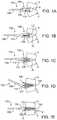
- a method (not claimed) for inserting an intervertebral disc prosthesis 104 into an intervertebral space IS between two adjacent vertebrae Vfirst involves inserting the disc prosthesis 104 partway into the space IS while the prosthesis 104 is constrained ( Fig. 1A ).
- constrainedit is meant that endplates 106 of the prosthesis 104 are not free to articulate (move) about a core 112 ( Figs. 1B-1E ) of the prosthesis 104.
- an insertion device 102may be used.
- Such an insertion device 102may suitably include a grasping member 110 coupled with an elongate shaft 108.
- the insertion device 102may include a handle, an actuator to control the grasping member 110 and/or any other suitable features, some of which are described further below.
- the prosthesis 104may be inserted as far into the intervertebral space IS under constraint as is desired. In some embodiments, for example, the prosthesis 104 is inserted under constraint approximately one-third of the way into the space IS. In other embodiments, the prosthesis 104 may be inserted less than one-third of the way, closer to one-half of the way, or any other suitable distance into the space IS.
- the insertion device 102may be removed, thus releasing the prosthesis 104 from constraint. From this point forward, the endplates 106 of the prosthesis 104 are free to move about the prosthesis core 112. Examples of such a prosthesis 104 with endplates 106 and core 112 are described by the assignees of the present application in U.S. Patent Application Serial Nos. 10/855,817 and 10/855,253 , although any other suitable prosthesis may be used in various embodiments.
- the insertion device 102may be used to push the unconstrained prosthesis 104 farther into the intervertebral space.
- one or more separate pusher devicesmay be used in addition to or instead of the insertion device 102 for pushing the prosthesis 104 farther into the space IS.
- Figs. 1C and 1Ddemonstrate that in one embodiment the grasping member 110 of the insertion device 102 is adapted to push individually against the upper ( Fig. 1C ) and lower (Fig. ID) endplates 106.
- the grasping member 110may also be adapted to push simultaneously against the upper and lower endplates 106, thus pushing the prosthesis 104 as a unit farther into the intervertebral space IS.
- the methodreduces the need for increasing the height of the intervertebral space IS by distracting the vertebrae V away from each other. Because the endplates 106 are free to articulate, the prosthesis 104 is better able to conform to the intervertebral space IS, thus reducing trauma to the vertebrae V and also limiting trauma to surrounding structures caused by over-distraction.
- the unconstrained prosthesis 104may be inserted as far into the intervertebral space IS as is desired.
- the prosthesis 104is pushed far enough into the space IS so that a center of rotation of the prosthesis 104 is closer to a posterior edge P ( Fig. 1E ) of the vertebrae V than to an anterior edge A of the vertebrae V.
- any other suitable insertion distance or depthmay be used.
- the method just describedmay include fewer steps or additional steps.
- a spreader deviceis inserted between the two vertebrae V to spread them apart before inserting the constrained prosthesis 104.
- An example of such a spacing deviceis described in PCT Patent Application Number 2004/000171 .
- the insertion device 102is typically sized to fit between opposing jaws of the spreader device.
- the spreader deviceis removed from the intervertebral space IS, and the prosthesis 104 is released from constraint and inserted the rest of the way into the space IS.
- a midline indicator devicemay be used to facilitate the location of a midline on one or both of the two adjacent vertebrae V.
- An example of such a midline indicator deviceis described in PCT Patent Application Number 2004/000170 .
- the midline indicatoris used before the disc prosthesis 104 is inserted.
- an insertion device 120 for inserting an intervertebral disc prosthesis 140suitably includes an elongate shaft 126, a grasping member 122 coupled with the distal end of the shaft 126, and a handle 128 at the proximal end of the shaft 120, including one or more actuators 130 for controlling movement of the grasping member 122.
- One or more rods 124 or other connectorsextend from the grasping member 122 through the shaft 126 to the actuator 130.
- the grasping member 122comprises two opposable tongs or jaws, which may be moved closer together or farther apart (double-headed arrows) via the actuator 130 and rods 124.
- the actuator 130 shownis a thumb screw.
- scissor-type mechanisms, spring loaded tongs, a triggering mechanism or any other suitable grasping and actuating meansmay be used. Any suitable material or combination of materials may be used to manufacture the insertion device, including but not limited to stainless steel and/or other suitable metals.
- the insertion device 120may grasp a disc prosthesis 140 such that the grasping member 122 does not protrude beyond an outer edge 141 of the prosthesis 140.
- the grasping member 122holds onto an inner portion of the prosthesis 140, so that it will not extend beyond the lateral edges 141 of the prosthesis 140.
- This configurationis advantageous during insertion, as the grasping member 122 is essentially out of the way, within the outer edge 141 of the prosthesis 140.
- Fig. 2Cis a side view of a distal end of the insertion device 120 shown in Figs. 2A and 2B .
- the disc prosthesis 140includes a core 146 and two endplates 142.
- Each endplate 142includes an inner rim 144 that contacts the core 146 and a fin 148 for enhancing attachment to vertebral bone.
- the grasping member 122 of the insertion device 120grasps the inner rims 144 of the endplates 142, thus positioning it within the outer edges 141 of the endplates 142.
- a separate pusher device 150may be used to push an unconstrained prosthesis 140 farther into an intervertebral space.
- the pusher device 150is typically constructed of stainless steel or other suitable metal and suitably includes an elongate shaft 152, a pusher member 154 at the distal end of the shaft 152, and a handle 158 at the proximal end of the shaft 152.
- the pusher member 154includes a concave inner portion 156 for pushing against the inner rims 144 of endplates 142 of the prosthesis 140.
- the concave portion 156may be tapered and/or rounded to facilitate pushing against upper and lower endplates 142 individually while also allowing for simultaneous pushing against both endplates 142.
- the pusher device 150may have any of a number of alternative configurations, shapes, sizes and the like. In some embodiments, multiple pusher devices 150 of different configurations and/or sizes are provided to allow a physician to select one or more desired devices 150.
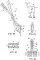
- the spreader device 10generally includes distally located opposable jaws 12, a slidable pusher member 45 and an actuator 15.
- the opposable jaws 12are carried by arms 14 which form part of a scissors-type mechanism having a single hinge point 15.
- Handles 16 on the proximal end of the deviceare used to manipulate the opposable jaws 12.
- arms 14translate the actuation motion to the single hinge point scissors type mechanism 15. This causes the opposable jaws 12 to open or close.
- the jaws 12have opposing surfaces 18 formed with ribs 20 and transverse slots 22 which extend for the height of the jaws as seen in Fig. 4B . At their free ends, the jaws 12 are provided with relatively sharp tips or blades 24 having curved extremities 26.
- Figs. 4A and 4Billustrate how the handles 14 are inclined relative to the jaws 12. Manipulation of the handles 16 by moving them causes the jaws 12 to open or close. Other examples include a double hinge instead of the single hinge 15 which would pivot the jaws apart from one another when the handles 16 are displaced towards one another.
- the insertion device 10 illustrated in Figs. 4A-4Eis designed for placement of an intervertebral prosthetic disc 30.
- a prosthetic disc 30comprises opposing endplates 32 which are located on opposite sides of a central core 34.
- the opposing endplates 32articulate about the central core 34.
- the prosthetic disc 30also comprises projecting fins 36 which are aligned with matching slots 40 in the vertebrae 38 during implantation. Typically slots 40 are saw cut into the vertebrae 38.
- FIGs. 4D and 5A method (not claimed) of inserting the intervertebral prosthesis is illustrated in Figs. 4D and 5 .
- the vertebrae 38are distracted by a distance sufficient for at least partial insertion of the prosthesis 30.
- the tips 24 of the opposable jaws 12are inserted between the vertebrae 38 with the slots 22 in the opposable jaws 12 aligned with the slots in the vertebrae 40.
- the handles 16are then manipulated to force the opposable jaws 12 apart which also forces the vertebrae 38 apart from one another, creating a gap.
- the prosthesis 30is then inserted into the gap 42 between the opposable jaws 12 where it is held therein with fins 36 engaged with the corresponding slots 22.
- the prosthesis 30is then slipped distally in the gap while being guided by the fins 36 cooperating with the slots 22.
- the prosthesis 30is moved through the inter-jaw gap and past the jaw tips 24 in order to locate the prosthesis 30 between the vertebrae 38 with fins 36 in the vertebral cut slots 40.
- the slots 22 in the opposable jaws 12help to guide the fins 36 into the vertebral cut slots 40.
- Figure 4Cillustrates the jaws 12 inclined towards one another, in the direction towards the tips 24.
- the gap 42 between the jaws 12 at the topis large enough for insertion of the prosthesis 30 between them at that point. Therefore, in an alternative method (not claimed) of placing the prosthesis, the prosthesis 30 may be located initially in the gap 42 and then it may be pushed down towards the tip 24, forcing the jaws 12 open and similarly forcing the vertebrae 38 apart from one another.
- a pusher 45may be used to hold, position and drive the prosthesis 30 during the placement procedure.
- a forcemay be applied manually to pusher 45 or it may be tapped on the upper end to drive the prosthesis downward.
- the prosthesis placement procedure(not claimed) may be modified so that the initial distraction of the vertebra 38 is achieved by manipulation of the handles 16 and then a force may be applied manually to the pusher 45 or it may be tapped in order to create the final intervertebral gap and placement of the prosthesis 30.
- the spreader device 10serves both to facilitate insertion of the prosthesis 30 between the vertebrae 38 and also to ensure that the prosthesis 30 is accurately guided into position with its fins 36 lined up with the vertebral slots 40.
- Fig. 5shows in greater detail (solid-tipped arrows) the various motions involved in inserting the spreader device 10 into the intervertebral space and manipulating the handles 16 to force open the jaws 12 and thus increased the height of the intervertebral space between the two adjacent vertebrae 38.
- this or other spreader devices 10is optional.
- Figs. 6A-6Dshow another optional device.
- a midline indicator device 210such as the one shown is described in greater detail in PCT Patent Application Number 2004/000170 .
- the midline indicator 210suitably includes an elongate shaft 212 and a body 214 coupled with one end of the shaft 212.
- the shaft 212may be made of one or more radiopaque materials, such as but not limited to stainless steel, titanium or the like.
- the shaft 212may be radiolucent.
- the body 214is made of one or more radiolucent materials, such as a polymer, so that it is not visible on radiographs.
- Embedded in the body 214are two elongate radiopaque markers 216, also made of any suitable radiopaque material(s).
- the markers 216are parallel to the shaft 212 and are located on opposite sides and equidistant from the shaft 212.
- Figs. 7A and 7Bdemonstrate a method (not claimed) for using the midline indicator to find a vertebral body midline 222.
- Fig. 7Ashows, in anterior view, adjacent upper 218 and lower 220 vertebrae.
- the surgeonuses the shaft 212 to insert the body 214 between the vertebrae 218, 220.
- the surgeonattempts to position the shaft 212 at the vertebral midline 222, and a radiograph is taken of the vertebrae 218, 220 and indicator 210 from the anteriorposterior (A-P) direction.
- the surgeonthen examines the radiograph to determine whether the markers 216 are equidistant laterally from the lateral osseous edges 223 of the vertebrae 218, 220-i.e., that the distance 225 is the same on both sides, and that the markers 216 are aligned with the pedicles.
- the shaft 212 and markers 216are properly aligned in the A-P direction, they will appear as dots on the radiograph. If the midline indicator 210 is turned, however, as is demonstrated by the dotted lines in Fig. 7B , the shaft 212 and markers 216 will show up as lines or stretched-out dots on the radiograph.
- the A-P direction of the radiographis shown by 224, with misalignment of the indicator 210 shown by angles 0.
- the mark 226may be made by any suitable means, such as by burning with an electrocautery device, marking with a marking pen, inserting a pin, or the like. After one or more midline marks 226 are made, the midline indicator 210 is removed and the disc prosthesis (not shown) is inserted. Again, the midline finding step is optional.
Landscapes
- Health & Medical Sciences (AREA)
- Biomedical Technology (AREA)
- Engineering & Computer Science (AREA)
- Orthopedic Medicine & Surgery (AREA)
- Neurology (AREA)
- Life Sciences & Earth Sciences (AREA)
- Transplantation (AREA)
- Heart & Thoracic Surgery (AREA)
- Animal Behavior & Ethology (AREA)
- General Health & Medical Sciences (AREA)
- Public Health (AREA)
- Veterinary Medicine (AREA)
- Vascular Medicine (AREA)
- Oral & Maxillofacial Surgery (AREA)
- Cardiology (AREA)
- Surgery (AREA)
- Physical Education & Sports Medicine (AREA)
- Molecular Biology (AREA)
- Medical Informatics (AREA)
- Nuclear Medicine, Radiotherapy & Molecular Imaging (AREA)
- Ophthalmology & Optometry (AREA)
- Prostheses (AREA)
- Surgical Instruments (AREA)
Description
- This invention relates to medical devices and methods (the latter not claimed). More specifically, the invention relates to intervertebral disc prostheses.
- Back pain takes an enormous toll on the health and productivity of people around the world. According to the American Academy of Orthopedic Surgeons, approximately 80 percent of Americans will experience back pain at some time in their life. In just the year 2000, approximately 26 million visits were made to physicians' offices due to back problems in the United States. On any one day, it is estimated that 5% of the working population in America is disabled by back pain.
- One common cause of back pain is injury, degeneration and/or dysfunction of one or more intervertebral discs. Intervertebral discs are the soft tissue structures located between each of the thirty-three vertebral bones that make up the vertebral (spinal) column. Essentially, the discs allow the vertebrae to move relative to one another. The vertebral column and discs are vital anatomical structures, in that they form a central axis that supports the head and torso, allow for movement of the back, and protect the spinal cord, which passes through the vertebrae in proximity to the discs.
- Discs often become damaged due to wear and tear or acute injury. For example, discs may bulge (herniate), tear, rupture, degenerate or the like. A bulging disc may press against the spinal cord or a nerve exiting the spinal cord, causing "radicular" pain (pain in one or more extremities caused by impingement of a nerve root). Degeneration or other damage to a disc may cause a loss of "disc height," meaning that the natural space between two vertebrae decreases. Decreased disc height may cause a disc to bulge, facet loads to increase, two vertebrae to rub together in an unnatural way and/or increased pressure on certain parts of the vertebrae and/or nerve roots, thus causing pain. In general, chronic and acute damage to intervertebral discs is a common source of back related pain and loss of mobility.
- When one or more damaged intervertebral discs cause a patient pain and discomfort, surgery is often required. Traditionally, surgical procedures for treating intervertebral discs have involved discectomy (partial or total removal of a disc), with or without fusion of the two vertebrae adjacent to the disc. Fusion of the two vertebrae is achieved by inserting bone graft material between the two vertebrae such that the two vertebrae and the graft material grow together. Oftentimes, pins, rods, screws, cages and/or the like are inserted between the vertebrae to act as support structures to hold the vertebrae and graft material in place while they permanently fuse together. Although fusion often treats the back pain, it reduces the patient's ability to move, because the back cannot bend or twist at the fused area. In addition, fusion increases stresses at adjacent levels of the spine, potentially accelerating degeneration of these discs.
- In an attempt to treat disc related pain without fusion, an alternative approach has been developed, in which a movable, implantable, artificial intervertebral disc (or "disc prosthesis") is inserted between two vertebrae. A number of different intervertebral disc prostheses are currently being developed. For example, the inventors of the present invention have developed disc prostheses described in
U.S. Patent Application Serial Nos. 10/855,817 and10/855,253
Medtronic Sofamor Danek, Inc.), the ProDisc® or ProDisc-C® (from Synthes Stratec, Inc.), and the PCM disc (provided by Cervitech, Inc.). - To insert an artificial intervertebral disc prosthesis, and indeed for performing most discrelated surgeries, it is typically necessary to gain access to the disc and the intervertebral space from an anterior to posterior direction (i.e., through the front of the patient), to avoid coming in contact with the spinal cord. Thus, surgical procedures on a disc are typically approached anteriorly through the neck or abdomen, depending on which disc (or discs) is being repaired. Methods for inserting a disc prosthesis generally involve removing the damaged disc, preparing the surfaces of the two vertebral bones to receive the prosthesis, spreading the two vertebrae apart using one or more spreading devices, and inserting the prosthesis into the space between the two vertebrae. Examples of such methods are described in
U.S. Patent Nos. 6,478,800 ,6,235,030 ,6,652,533 ,6,689,132 ,6,261,296 and6,666,866 , and inU.S. Patent Application Nos. 2001/0031969 ,2001/0029377 ,2003/0153916 ,2002/0198532 ,2004/0024407 ,2003/0216737 ,2003/0204261 ,2003/0135220 and2003/0014114 . Due to the invasive nature of such procedures, one important goal is to reduce invasiveness, thus causing as little trauma to tissues surrounding the surgical site as possible. - The main drawback of currently available methods for inserting intervertebral disc prostheses is that they require a larger amount of spreading apart (or "distraction") of the two vertebrae than is optimal. Over-distraction is necessary when using such methods because it is important to insert the disc prosthesis all the way into the disc space, to position the center of rotation of the prosthesis closer to the posterior portion of the vertebrae than to the anterior portion. This allows the vertebrae to move as they were intended and avoids placing undue strain on the facet joints of the vertebrae or on other structures. To push a prosthesis toward
the back of a disc space, however, it is typically necessary to spread the two vertebrae apart widely, since the anterior portion of the disc space is usually wider (or higher) than the posterior portion. In some methods, an artificial disc is placed by placing a first endplate into the space, placing a second endplate into the space, and then spreading the vertebrae wide enough to wedge a core in between the two endplates. In other methods, the vertebrae are spread apart as far as practicable, the whole prosthesis is inserted while one or more spreading devices are in place, and not until the prosthesis is completely inserted is the spreading device removed. In either case, as well as in other currently available methods, the two vertebrae adjacent the prosthesis are typically spread farther apart than would be desirable for a longer amount of time than would be desirable. In some cases, the posterior longitudinal ligament (PLL) is released, or "cut," to enable sufficient distraction for disc placement. - Distracting vertebrae can damage muscles, ligaments, nerves and/or other tissues in and around the vertebral column. Such damage may actually cause the patient to experience as much, or even more, pain after surgery than was caused by the original disc problem.
- Therefore, as the use of intervertebral disc prostheses increases, an increasing need exists for improved methods and apparatus for inserting such prostheses. Ideally, such intervertebral prosthesis insertion methods and devices would provide for insertion of a prosthesis a desired distance into an intervertebral space while reducing the need for intervertebral distraction, thus preventing or at least reducing trauma to surrounding tissues. Also ideally, such insertion methods and devices would be relatively simple and easy to use, thereby reducing the overall invasiveness of the procedure. At least some of these objectives will be met by the present invention.
- A number of exemplary intervertebral disc prostheses are listed above. Published
US patent applications 2002/0035400A1 and2002/0128715A1 describe disc implants which comprise opposing plates with a core between them over which the plates can slide. The core receives one or more central posts, which are carried by the plates and which locate in opposite ends of a central opening in the core. Such arrangements limit the load bearing area available between the plates and core.WO2002091909A2 relates to devices and instruments for implant insertion through a posterior lateral opening to the disc space. The instruments include an implant inserter, and the devices include a spinal fusion implant engageable by the implant inserter. The implant provides bilateral support of the adjacent vertebrae when inserted into the disc space from a postero-lateral approach.DE20310433U1 discloses a device assembled of a handle attached to a shaft with an axially movable cylindrical cover. A holding and positioning tool at the lower end of the shaft, comprising the gripping elements with a flat front area with a u-shaped space between them and stick-shaped projections protruding from the front surfaces of a thicker rear area can be locked in a holding position when the sleeve is moved towards the lower end. - Examples of instrument set for inserting an articulating intervertebral prosthesis into a space between two adjacent vertebrae include
WO 02/089701 A2 EP 1 153 582 A2 andWO 91/13598 A1 WO2/089701 A2 - Other patents related to intervertebral disc prostheses include
U.S. Patent Nos.: 4,759,766 ;4,863,47 4,997,432 ;5,071,43 5,370,69 5,401,26 5,507,81 5,534,030 ;5,556,43 5,674,296 ;5,702,45 5,824,09 5,865,84 5,989,29 6,001,130 ;6,022,37 6,039,763 ;6,156,06 6,162,25 6,315,79 6,348,07 6,368,350 ;6,416,55 6,592,624 ;6,607,558 and6,706,068 . Other patent applications related to intervertebral disc prostheses includeU.S. Patent Application Publication Nos.: 2003/0009224 ;2003/0074076 ;2003/0191536 ;2003/0208271 ;2003/0135277 ;2003/0199982 ;2001/0016773 and2003/0100951 . Other related patents includeWO 01/01893A1 EP 1344507 ,EP 1344506 ,EP 1250898 ,EP 1306064 ,EP 1344508 ,EP 1344493 ,EP 1417940 ,EP 1142544 , andEP 0333990 . - The present invention provides an instrument set for inserting an articulating intervertebral prosthesis into a space between two adjacent vertebrae according to claim 1. One advantage of the embodiments is that a disc prosthesis may be inserted with minimal or reduced intervertebral distraction, thus avoiding trauma to tissues in and around the insertion site. Reduced distraction is generally achieved by inserting a prosthesis into an intervertebral space while allowing endplates of the prosthesis to articulate during at least part of the insertion process. For the purposes of this application, to "articulate" means to move relative to another structure. Thus, allowing endplates of an intervertebral prosthesis to articulate means that endplates are free to move relative to each other, relative to a core of the prosthesis, relative to a ball and socket joint of the prosthesis, relative to a mobile or fixed center of rotation of the prosthesis and/or the like. Although the following description often focuses on disc prostheses having two endplates and a core, various examples of the insertion method may be applied to any other intervertebral disc prosthesis. Articulation of the endplates during insertion allows the prosthesis to be pushed posteriorly into a disc space without excessive intervertebral distraction or significant forces being applied to the vertebrae, thus achieving desirable positioning of the prosthesis while avoiding trauma to surrounding muscles, ligaments, nerves and the like.
- A method (not claimed) of inserting an intervertebral prosthesis into a space between two adjacent vertebrae involves inserting the prosthesis partway into the space under constraint to prevent endplates of the prosthesis from articulating, releasing the prosthesis from constraint, and inserting the unconstrained prosthesis farther into the space. As mentioned above, in some examples, the endplates of the constrained prosthesis are prevented from articulating about a core of the prosthesis, while the endplates of the unconstrained prosthesis are generally free to articulate about the core to help the prosthesis conform to the space between the two vertebrae. In alternative examples, the unconstrained endplates may be free to articulate about a ball and socket joint or other structure.
- In one embodiment, inserting the prosthesis partway under constraint involves grasping the endplates with an insertion tool such that they cannot move relative to the core and pushing the prosthesis partway into the space using the insertion tool. In such embodiments, releasing the prosthesis from constraint may involve loosening the insertion tool. In some embodiments, the loosened insertion tool may then be used to insert the unconstrained prosthesis farther into the intervertebral space. Additionally, or alternatively, a separate pusher tool may be used to insert the unconstrained prosthesis farther into the space.
- In some embodiments, inserting the constrained prosthesis partway into the space between the vertebrae involves inserting the prosthesis less than halfway into the space. In one embodiment, for example, the constrained prosthesis is inserted about one third of the way into the space and then subsequently inserted farther into the space. In alternative embodiments, the constrained prosthesis may be pushed more than halfway into the space, less than one third of the way into the space, or any other suitable distance into the space. The unconstrained prosthesis is then inserted any desired distance farther into the intervertebral space. In some embodiments, for example, the prosthesis is inserted sufficiently far into the space that a center of rotation of the prosthesis is closer to the posterior edges of the vertebrae than to the anterior edges of the vertebrae.
- In some examples, the prosthesis is inserted in approximately an anterior to posterior direction. In alternative examples, the prosthesis may be inserted in an anterolateral-toposterior direction, lateral-to-lateral direction or posterior-to-anterior
direction. Typically, inserting the unconstrained prosthesis farther into the space involves pushing the prosthesis into the space. In other examples, however, techniques other than pushing may be used to insert the prosthesis, such as pulling. In some embodiments, pushing the prosthesis farther into the space involves individually pushing upper and lower endplates of the prosthesis. Alternatively, or additionally, the upper and lower endplates of the prosthesis may be simultaneously pushed into the intervertebral space. In various embodiments, individual and simultaneous endplate pushing may be performed using the grasping device, a separate pusher device, or both. - A method (not claimed) may also include inserting a vertebral spacing device at least partway into the space and manipulating the spacing device to increase a height of the space. An example of such a spacing device is described by the assignees of the present application in
PCT Patent Application Number 2004/000171, filed January 26, 2004 (Attorney Docket Number currently being updated with International Bureau to 022031-001100PC. The spacing step is typically performed before inserting the constrained prosthesis partway into the intervertebral space. In some examples, inserting the constrained prosthesis partway into the intervertebral space comprises sliding the prosthesis between two opposing jaws of the spacing device. In such an example, inserting the constrained prosthesis partway into the space may optionally further involve sliding at least one fin on at least one outer surface of the endplates through at least one corresponding slot in the opposing jaws. In one
example, such a fin (or fins) may then be slid into a corresponding slot formed in one of the vertebrae. - Some examples also involve using a vertebral midpoint indicator device to locate a midpoint of at least one of the two vertebrae, and marking the midpoint on one or both of the two vertebrae. An example of a midline indicator device is described by the assignees of the present application in
PCT Patent Application Number 2004/000170, filed January 26, 2004 (Attorney Docket Number currently being updated with International
Bureau to 022031-000900PC). Midline finding and marking are typically performed before inserting the constrained prosthesis partway into the intervertebral space. In some examples, locating the midpoint involves inserting the vertebral midpoint indicator device into the space between the vertebrae and imaging the midpoint indicator device using a radiographic imaging device. - A method (not claimed) of inserting an intervertebral prosthesis into a space between two adjacent vertebrae involves sliding the prosthesis partway into the space between the vertebrae between two opposing jaws of a spacing device, removing the spacing device from the space to release the prosthesis from constraint, and pushing the unconstrained prosthesis farther into the space while allowing endplates of the prosthesis to articulate. In this method, the endplates of the prosthesis are constrained from articulating when the prosthesis is disposed between the jaws. Again, in some examples, the unconstrained endplates articulate about a core of the prosthesis, while in alternative examples they may articulate about a ball and socket joint or other structure. Such a method may optionally further include inserting the spacing device at least partway into the space and manipulating the spacing device to increase a height of the space. Any of the additional or alternative features described above may also be applied in various examples.
- A device for inserting an intervertebral prosthesis into a space between two adjacent vertebrae includes: an elongate rigid shaft having a proximal end and a distal end; an adjustable grasping member coupled with the distal end for releasably grasping endplates of the intervertebral prosthesis; and an actuator disposed near the proximal end of the shaft and coupled with the grasping member for adjusting the grasping member to grasp and release the prosthesis. The grasping member is adapted to grasp the prosthesis such that the endplates are constrained from articulating and such that the outer diameter of the grasping member does not extend beyond a largest diameter of the endplates. Additionally, the grasping member is adapted for pushing the prosthesis into the space between the two vertebrae either while grasping the prosthesis or after releasing the prosthesis.
- In some examples, the grasping member comprises movable opposing jaws adapted to simultaneously grasp inner rims of the endplates. Such a grasping member may, for example, be coupled with the actuator via at least one rod extending through the shaft.
For example, the grasping member may include a first half coupled with a first movable rod extending from the actuator and a second half coupled with a second movable rod extending from the actuator. In some examples, the actuator comprises a thumb screw adapted to move the first and second rods closer together and farther apart by turning the thumb screw in opposite directions. In alternative examples, the actuator may include, but is not limited to, a trigger, tongs and a movable handle. In a number of examples, the device is shaped to pass between two opposable jaws of a vertebral spacing device disposed between the two adjacent vertebrae. Also in some examples, the grasping member may be adapted to push the endplates either simultaneously or individually into the space. - In an aspect of the present invention, an instrument set for inserting an intervertebral prosthesis into a space between two adjacent vertebrae includes a prosthesis grasping device for grasping the prosthesis and pushing the prosthesis at least partway into the space and at least one prosthesis pusher device for pushing the prosthesis farther into the space. The grasping device is similar to the device described immediately above and may include any of the described features. The pusher device may include: an elongate shaft having a proximal end and a distal end; a concave pusher portion disposed at the distal end, the pusher portion adapted to push the endplates either simultaneously or individually into the space; and a handle disposed at the proximal end.
- In some examples, the system further includes a vertebral spacing device for increasing a height of the space between the two vertebrae. An example of such a spacing device is described in
PCT Patent Application Number 2004/000171 . In such examples, the grasping member is adapted to slide through the vertebral spacing device disposed between two adjacent vertebrae. Optionally, the pusher device may also be adapted to slide through the spacing device. - The instrument may optionally further include a vertebral body midline indicator device for locating a midline on a vertebral body of at least one of the two vertebrae. An example of a midline indicator device is described in
PCT Patent Application Number 2004/000170 . - These and other aspects and embodiments will be described in further detail below, with reference to the drawing figures.
Figs. 1A-1E demonstrate a method (not claimed) for inserting an intervertebral disc prosthesis.Figs. 2A and 2B are top views of a grasping device for inserting an intervertebral disc prosthesis.Fig. 2C is a side view of the distal end of the device inFigs. 2A and 213.Fig. 3 is a top view of a pusher device for inserting an intervertebral disc prosthesis.Figs. 4A-4E are various views of a spreader device for distracting two adjacent vertebrae for inserting an intervertebral disc prosthesis.Fig. 5 demonstrates the spreading action of the spreader device inFigs. 4A-4E .Figs. 6A-6D are various views of a vertebral body midline indicator device.Figs. 7A and 7B demonstrate indication of vertebral midline using the device inFigs. 6A-6D .- Referring to
Figs. 1A-1E , a method (not claimed) for inserting anintervertebral disc prosthesis 104 into an intervertebral space IS between two adjacent vertebrae V first involves inserting thedisc prosthesis 104 partway into the space IS while theprosthesis 104 is constrained (Fig. 1A ). By "constrained" it is meant thatendplates 106 of theprosthesis 104 are not free to articulate (move) about a core 112 (Figs. 1B-1E ) of theprosthesis 104. To insert theprosthesis 104 partway under constraint, aninsertion device 102 may be used. Such aninsertion device 102 may suitably include a graspingmember 110 coupled with anelongate shaft 108. At an end opposite the grasping member 110 (not shown), theinsertion device 102 may include a handle, an actuator to control the graspingmember 110 and/or any other suitable features, some of which are described further below. - The
prosthesis 104 may be inserted as far into the intervertebral space IS under constraint as is desired. In some embodiments, for example, theprosthesis 104 is inserted under constraint approximately one-third of the way into the space IS. In other embodiments, theprosthesis 104 may be inserted less than one-third of the way, closer to one-half of the way, or any other suitable distance into the space IS. - As shown in
Fig. 1B , once theprosthesis 104 is inserted partway under constraint, theinsertion device 102 may be removed, thus releasing theprosthesis 104 from constraint. From this point forward, theendplates 106 of theprosthesis 104 are free to move about theprosthesis core 112. Examples of such aprosthesis 104 withendplates 106 andcore 112 are described by the assignees of the present application inU.S. Patent Application Serial Nos. 10/855,817 and10/855,253 - Referring now to
Figs. 1C-1E , in some embodiments theinsertion device 102 may be used to push theunconstrained prosthesis 104 farther into the intervertebral space. In some embodiments, one or more separate pusher devices (not shown) may be used in addition to or instead of theinsertion device 102 for pushing theprosthesis 104 farther into the space IS.Figs. 1C and 1D demonstrate that in one embodiment the graspingmember 110 of theinsertion device 102 is adapted to push individually against the upper (Fig. 1C ) and lower (Fig. ID)endplates 106. As shown in Fig. IE, the graspingmember 110 may also be adapted to push simultaneously against the upper andlower endplates 106, thus pushing theprosthesis 104 as a unit farther into the intervertebral space IS. - By inserting the
prosthesis 104 farther into the space IS while it is unconstrained, thus allowing theendplates 106 to articulate about thecore 112, the method reduces the need for increasing the height of the intervertebral space IS by distracting the vertebrae V away from each other. Because theendplates 106 are free to articulate, theprosthesis 104 is better able to conform to the intervertebral space IS, thus reducing trauma to the vertebrae V and also limiting trauma to surrounding structures caused by over-distraction. - The
unconstrained prosthesis 104 may be inserted as far into the intervertebral space IS as is desired. In some embodiments, for example, theprosthesis 104 is pushed far enough into the space IS so that a center of rotation of theprosthesis 104 is closer to a posterior edge P (Fig. 1E ) of the vertebrae V than to an anterior edge A of the vertebrae V. In alternative embodiments, any other suitable insertion distance or depth may be used. Once a desired amount of insertion is achieved, theinsertion device 102 is removed and theprosthesis 104 is in place between the two adjacent vertebrae V. - The method just described (not claimed) may include fewer steps or additional steps. For example, a spreader device is inserted between the two vertebrae V to spread them apart before inserting the
constrained prosthesis 104. An example of such a spacing device is described inPCT Patent Application Number 2004/000171 .Theinsertion device 102 is typically sized to fit between opposing jaws of the spreader device. When theprosthesis 104 is partially inserted, the spreader device is removed from the intervertebral space IS, and theprosthesis 104 is released from constraint and inserted the rest of the way into the space IS. A midline indicator device may be used to facilitate the location of a midline on one or both of the two adjacent vertebrae V. An example of such a midline indicator device is described inPCT Patent Application Number 2004/000170 . Typically, the midline indicator is used before thedisc prosthesis 104 is inserted. - Referring now to
Figs. 2A-2C , one embodiment of aninsertion device 120 for inserting anintervertebral disc prosthesis 140 suitably includes anelongate shaft 126, a graspingmember 122 coupled with the distal end of theshaft 126, and ahandle 128 at the proximal end of theshaft 120, including one ormore actuators 130 for controlling movement of the graspingmember 122. One ormore rods 124 or other connectors extend from the graspingmember 122 through theshaft 126 to theactuator 130. In the embodiment shown, for example, the graspingmember 122 comprises two opposable tongs or jaws, which may be moved closer together or farther apart (double-headed arrows) via theactuator 130 androds 124. Theactuator 130 shown is a thumb screw. In alternative embodiments, scissor-type mechanisms, spring loaded tongs, a triggering mechanism or any other suitable grasping and actuating means may be used. Any suitable material or combination of materials may be used to manufacture the insertion device, including but not limited to stainless steel and/or other suitable metals. - As shown in
Fig. 2B , theinsertion device 120 may grasp adisc prosthesis 140 such that the graspingmember 122 does not protrude beyond anouter edge 141 of theprosthesis 140. In other words, the graspingmember 122 holds onto an inner portion of theprosthesis 140, so that it will not extend beyond thelateral edges 141 of theprosthesis 140. This configuration is advantageous during insertion, as the graspingmember 122 is essentially out of the way, within theouter edge 141 of theprosthesis 140. Fig. 2C is a side view of a distal end of theinsertion device 120 shown inFigs. 2A and 2B . It is more readily seen that thedisc prosthesis 140 includes acore 146 and twoendplates 142. Eachendplate 142 includes aninner rim 144 that contacts thecore 146 and afin 148 for enhancing attachment to vertebral bone. The graspingmember 122 of theinsertion device 120 grasps theinner rims 144 of theendplates 142, thus positioning it within theouter edges 141 of theendplates 142.- Referring now to
Fig. 3 , in some embodiments aseparate pusher device 150 may be used to push anunconstrained prosthesis 140 farther into an intervertebral space. Thepusher device 150 is typically constructed of stainless steel or other suitable metal and suitably includes anelongate shaft 152, apusher member 154 at the distal end of theshaft 152, and ahandle 158 at the proximal end of theshaft 152. Thepusher member 154 includes a concaveinner portion 156 for pushing against theinner rims 144 ofendplates 142 of theprosthesis 140. Theconcave portion 156 may be tapered and/or rounded to facilitate pushing against upper andlower endplates 142 individually while also allowing for simultaneous pushing against bothendplates 142. In alternative embodiments, thepusher device 150 may have any of a number of alternative configurations, shapes, sizes and the like. In some embodiments,multiple pusher devices 150 of different configurations and/or sizes are provided to allow a physician to select one or more desireddevices 150. - Referring now to
Figs. 4A-4E , aspreader device 10 for spreading adjacent vertebrae to facilitateintervertebral disc prosthesis 30 insertion is shown. Again, thedevice 10 is described in greater detail inPCT Patent Application Number 2004/000171 . Thespreader device 10 generally includes distally locatedopposable jaws 12, aslidable pusher member 45 and anactuator 15. Theopposable jaws 12 are carried byarms 14 which form part of a scissors-type mechanism having asingle hinge point 15.Handles 16 on the proximal end of the device are used to manipulate theopposable jaws 12. When thehandles 16 are actuated,arms 14 translate the actuation motion to the single hinge pointscissors type mechanism 15. This causes theopposable jaws 12 to open or close. Thejaws 12 have opposingsurfaces 18 formed withribs 20 andtransverse slots 22 which extend for the height of the jaws as seen inFig. 4B . At their free ends, thejaws 12 are provided with relatively sharp tips orblades 24 havingcurved extremities 26. Figs. 4A and 4B illustrate how thehandles 14 are inclined relative to thejaws 12. Manipulation of thehandles 16 by moving them causes thejaws 12 to open or close. Other examples include a double hinge instead of thesingle hinge 15 which would pivot the jaws apart from one another when thehandles 16 are displaced towards one another.- The
insertion device 10 illustrated inFigs. 4A-4E is designed for placement of anintervertebral prosthetic disc 30. Such aprosthetic disc 30 comprises opposingendplates 32 which are located on opposite sides of acentral core 34. The opposingendplates 32 articulate about thecentral core 34. Theprosthetic disc 30 also comprises projectingfins 36 which are aligned with matchingslots 40 in thevertebrae 38 during implantation. Typicallyslots 40 are saw cut into thevertebrae 38. - A method (not claimed) of inserting the intervertebral prosthesis is illustrated in
Figs. 4D and5 . In order to place theprosthesis 30, thevertebrae 38 are distracted by a distance sufficient for at least partial insertion of theprosthesis 30. To achieve this, thetips 24 of theopposable jaws 12 are inserted between thevertebrae 38 with theslots 22 in theopposable jaws 12 aligned with the slots in thevertebrae 40. Thehandles 16 are then manipulated to force theopposable jaws 12 apart which also forces thevertebrae 38 apart from one another, creating a gap. Theprosthesis 30 is then inserted into thegap 42 between theopposable jaws 12 where it is held therein withfins 36 engaged with the correspondingslots 22. Theprosthesis 30 is then slipped distally in the gap while being guided by thefins 36 cooperating with theslots 22. Theprosthesis 30 is moved through the inter-jaw gap and past thejaw tips 24 in order to locate theprosthesis 30 between thevertebrae 38 withfins 36 in thevertebral cut slots 40. Theslots 22 in theopposable jaws 12 help to guide thefins 36 into thevertebral cut slots 40. Figure 4C illustrates thejaws 12 inclined towards one another, in the direction towards thetips 24. Thegap 42 between thejaws 12 at the top is large enough for insertion of theprosthesis 30 between them at that point. Therefore, in an alternative method (not claimed) of placing the prosthesis, theprosthesis 30 may be located initially in thegap 42 and then it may be pushed down towards thetip 24, forcing thejaws 12 open and similarly forcing thevertebrae 38 apart from one another. Apusher 45 may be used to hold, position and drive theprosthesis 30 during the placement procedure. A force may be applied manually topusher 45 or it may be tapped on the upper end to drive the prosthesis downward.- Alternatively, the prosthesis placement procedure (not claimed) may be modified so that the initial distraction of the
vertebra 38 is achieved by manipulation of thehandles 16 and then a force may be applied manually to thepusher 45 or it may be tapped in order to create the final intervertebral gap and placement of theprosthesis 30. Thespreader device 10 serves both to facilitate insertion of theprosthesis 30 between thevertebrae 38 and also to ensure that theprosthesis 30 is accurately guided into position with itsfins 36 lined up with thevertebral slots 40. Fig. 5 shows in greater detail (solid-tipped arrows) the various motions involved in inserting thespreader device 10 into the intervertebral space and manipulating thehandles 16 to force open thejaws 12 and thus increased the height of the intervertebral space between the twoadjacent vertebrae 38. As mentioned above, use of this orother spreader devices 10 is optional.Figs. 6A-6D show another optional device. As mentioned above, amidline indicator device 210 such as the one shown is described in greater detail inPCT Patent Application Number 2004/000170 . Themidline indicator 210 suitably includes anelongate shaft 212 and abody 214 coupled with one end of theshaft 212. Theshaft 212 may be made of one or more radiopaque materials, such as but not limited to stainless steel, titanium or the like. Alternatively, theshaft 212 may be radiolucent. Thebody 214 is made of one or more radiolucent materials, such as a polymer, so that it is not visible on radiographs. Embedded in thebody 214 are two elongateradiopaque markers 216, also made of any suitable radiopaque material(s). Themarkers 216 are parallel to theshaft 212 and are located on opposite sides and equidistant from theshaft 212.Figs. 7A and 7B demonstrate a method (not claimed) for using the midline indicator to find avertebral body midline 222.Fig. 7A shows, in anterior view, adjacent upper 218 and lower 220 vertebrae. To determine themidline 222, the surgeon uses theshaft 212 to insert thebody 214 between thevertebrae shaft 212 at thevertebral midline 222, and a radiograph is taken of thevertebrae indicator 210 from the anteriorposterior (A-P) direction. The surgeon then examines the radiograph to determine whether themarkers 216 are equidistant laterally from the lateralosseous edges 223 of thevertebrae 218, 220-i.e., that thedistance 225 is the same on both sides, and that themarkers 216 are aligned with the pedicles.- Additionally, if the
shaft 212 andmarkers 216 are properly aligned in the A-P direction, they will appear as dots on the radiograph. If themidline indicator 210 is turned, however, as is demonstrated by the dotted lines inFig. 7B , theshaft 212 andmarkers 216 will show up as lines or stretched-out dots on the radiograph. The A-P direction of the radiograph is shown by 224, with misalignment of theindicator 210 shown by angles 0. By consulting one or more radiographs and manipulating theindicator 210, the surgeon positions thehandle 212 of theindicator 210 at thevertebral midline 222. The surgeon may then make amark 226 in one ormore vertebrae midline 222. Themark 226 may be made by any suitable means, such as by burning with an electrocautery device, marking with a marking pen, inserting a pin, or the like. After one or more midline marks 226 are made, themidline indicator 210 is removed and the disc prosthesis (not shown) is inserted. Again, the midline finding step is optional. - Although the foregoing is a complete and accurate description of the invention, any suitable modifications, additions or the like may be made to the various embodiments without departing from the scope of the invention. Therefore, nothing described above should be interpreted as limiting the scope of the invention as it is described in the following claims.
Claims (13)
- An instrument set for inserting an articulating intervertebral prosthesis (104) into a space between two adjacent vertebrae, the set comprising:a prosthesis grasping device (102) configured to grasp two endplates (106, 142) of the prosthesis (104), thereby constraining the prosthesis such that the endplates (106, 142) are prevented from articulating about a core (112) of the prosthesis (104), and hold the prosthesis endplates (106, 142) stationary with respect to one another while pushing the prosthesis (104) into the space; andat least one prosthesis pusher device (150) configured for engaging and pushing the endplates (106) of the unconstrained prosthesis (104) into the space, wherein the endplates of the unconstrained prosthesis are free to articulate about the core to help the prosthesis conform to the space between the two vertebrae,wherein the pusher device (150) comprises:an elongate shaft 152 having a proximal end and a distal end;a rigid concave pusher portion (156) disposed at the distal end of the elongate shaft, the rigid concave pusher portion (156) adapted to push the endplates (106 , 142) into the space; anda handle (158) disposed at the proximal end of the elongate shaft (152)wherein the prosthesis grasping device (102) and the pusher device (150) are configured to be used in separate steps for inserting the prosthesis into the space between two adjacent vertebrae.
- A set as in claim 1, wherein the grasping device (102) comprises a grasping member (110, 122) which comprises movable opposing jaws adapted to grasp rims (144) of the two endplates (106, 142).
- A set as in claim 2, wherein the grasping device (102) is coupled with an actuator (130) to open and close the opposing jaws.
- A set as in any of the preceding claims, wherein the grasping device (102) is adapted to push the endplates (106, 142) simultaneously into the space.
- A set as in any of the preceding claims, wherein the pusher portion (154, 156) is adapted to push one of the endplates (106, 142) individually into the space.
- A set as in any of the preceding claims, wherein the pusher device (150) comprises multiple pusher devices of different configurations.
- A set as in any of the preceding claims, wherein the concave pusher portion (154, 156) includes a concave inner surface configured for pushing against rims of the endplates (106, 142).
- A set as in any of the preceding claims, wherein the handle (158) of the pusher (150) is configured to allow a force to be applied manually or by tapping the prosthesis into place.
- A set as in any of the preceding claims, further comprising an articulate intervertebral prosthesis (104) including two endplates (32, 106, 142), the prosthesis configured to be grasped by the prosthesis grasping device 102 and to be pushed into the space by the prosthesis pusher device (150).
- A set as in claim 9, further comprising a vertebral spacing device for increasing a height of the space between two vertebrae, the spacing device comprising moveable opposing jaws which have opposing surfaces which each comprise a transverse slot which extends for the height of the jaws, wherein the prosthesis comprises projecting fins which engage with the slots in the spacing device such that the prosthesis (104) can slide between the opposable jaws while being guided by the slots.
- A set as in claim 9 or 10, wherein the intervertebral prosthesis (104) includes a core (112) positioned between the two endplates (32, 106, 142) and the grasping device (102) is adapted to grasp the endplates (32, 106, 142) such that they are prevented from articulating about the core (112) of the prosthesis (104).
- A set as in any of the preceding claims, wherein the prosthesis pusher device (150) is tapered and/or rounded to facilitate pushing against the endplates (32, 106, 142) of the intervertebral prosthesis (104).
- A set as in any of the preceding claims, wherein the handle (158) of the prosthesis pusher device (150) is configured to allow a force to be applied by tapping the prosthesis (104) into place.
Applications Claiming Priority (3)
| Application Number | Priority Date | Filing Date | Title |
|---|---|---|---|
| US10/913,780US7585326B2 (en) | 2004-08-06 | 2004-08-06 | Methods and apparatus for intervertebral disc prosthesis insertion |
| EP05777414.3AEP1778135B1 (en) | 2004-08-06 | 2005-07-29 | Apparatus for intervertebral disc prosthesis insertion |
| PCT/US2005/027049WO2006017397A2 (en) | 2004-08-06 | 2005-07-29 | Methods and apparatus for intervertebral disc prosthesis insertion |
Related Parent Applications (2)
| Application Number | Title | Priority Date | Filing Date |
|---|---|---|---|
| EP05777414.3ADivisionEP1778135B1 (en) | 2004-08-06 | 2005-07-29 | Apparatus for intervertebral disc prosthesis insertion |
| EP05777414.3ADivision-IntoEP1778135B1 (en) | 2004-08-06 | 2005-07-29 | Apparatus for intervertebral disc prosthesis insertion |
Publications (2)
| Publication Number | Publication Date |
|---|---|
| EP3241529A1 EP3241529A1 (en) | 2017-11-08 |
| EP3241529B1true EP3241529B1 (en) | 2021-08-25 |
Family
ID=35758387
Family Applications (2)
| Application Number | Title | Priority Date | Filing Date |
|---|---|---|---|
| EP17172943.7AExpired - LifetimeEP3241529B1 (en) | 2004-08-06 | 2005-07-29 | Instrument set for inserting an articulating intervertebral disc prosthesis |
| EP05777414.3AExpired - LifetimeEP1778135B1 (en) | 2004-08-06 | 2005-07-29 | Apparatus for intervertebral disc prosthesis insertion |
Family Applications After (1)
| Application Number | Title | Priority Date | Filing Date |
|---|---|---|---|
| EP05777414.3AExpired - LifetimeEP1778135B1 (en) | 2004-08-06 | 2005-07-29 | Apparatus for intervertebral disc prosthesis insertion |
Country Status (6)
| Country | Link |
|---|---|
| US (13) | US7585326B2 (en) |
| EP (2) | EP3241529B1 (en) |
| JP (2) | JP4580986B2 (en) |
| KR (1) | KR20070048712A (en) |
| WO (1) | WO2006017397A2 (en) |
| ZA (1) | ZA200700943B (en) |
Families Citing this family (101)
| Publication number | Priority date | Publication date | Assignee | Title |
|---|---|---|---|---|
| US6936072B2 (en)* | 1999-08-18 | 2005-08-30 | Intrinsic Therapeutics, Inc. | Encapsulated intervertebral disc prosthesis and methods of manufacture |
| US7998213B2 (en)* | 1999-08-18 | 2011-08-16 | Intrinsic Therapeutics, Inc. | Intervertebral disc herniation repair |
| CA2425951C (en) | 1999-08-18 | 2008-09-16 | Intrinsic Therapeutics, Inc. | Devices and method for nucleus pulposus augmentation and retention |
| US20040010317A1 (en)* | 1999-08-18 | 2004-01-15 | Gregory Lambrecht | Devices and method for augmenting a vertebral disc |
| US7717961B2 (en) | 1999-08-18 | 2010-05-18 | Intrinsic Therapeutics, Inc. | Apparatus delivery in an intervertebral disc |
| US7553329B2 (en)* | 1999-08-18 | 2009-06-30 | Intrinsic Therapeutics, Inc. | Stabilized intervertebral disc barrier |
| US8323341B2 (en) | 2007-09-07 | 2012-12-04 | Intrinsic Therapeutics, Inc. | Impaction grafting for vertebral fusion |
| EP1624832A4 (en) | 1999-08-18 | 2008-12-24 | Intrinsic Therapeutics Inc | Devices and method for augmenting a vertebral disc nucleus |
| US7094258B2 (en)* | 1999-08-18 | 2006-08-22 | Intrinsic Therapeutics, Inc. | Methods of reinforcing an annulus fibrosis |
| US7972337B2 (en) | 2005-12-28 | 2011-07-05 | Intrinsic Therapeutics, Inc. | Devices and methods for bone anchoring |
| US8038713B2 (en) | 2002-04-23 | 2011-10-18 | Spinecore, Inc. | Two-component artificial disc replacements |
| US20080027548A9 (en) | 2002-04-12 | 2008-01-31 | Ferree Bret A | Spacerless artificial disc replacements |
| US6706068B2 (en) | 2002-04-23 | 2004-03-16 | Bret A. Ferree | Artificial disc replacements with natural kinematics |
| AU2003226586A1 (en) | 2002-09-19 | 2004-04-08 | Malan De Villiers | Intervertebral prosthesis |
| WO2004066884A1 (en)* | 2003-01-31 | 2004-08-12 | Spinalmotion, Inc. | Intervertebral prosthesis placement instrument |
| ZA200506029B (en) | 2003-01-31 | 2006-10-25 | Spinalmotion Inc | Spinal Midline Indicator |
| US6908484B2 (en) | 2003-03-06 | 2005-06-21 | Spinecore, Inc. | Cervical disc replacement |
| US7575599B2 (en) | 2004-07-30 | 2009-08-18 | Spinalmotion, Inc. | Intervertebral prosthetic disc with metallic core |
| US10052211B2 (en) | 2003-05-27 | 2018-08-21 | Simplify Medical Pty Ltd. | Prosthetic disc for intervertebral insertion |
| US7442211B2 (en)* | 2003-05-27 | 2008-10-28 | Spinalmotion, Inc. | Intervertebral prosthetic disc |
| US20090076614A1 (en)* | 2007-09-17 | 2009-03-19 | Spinalmotion, Inc. | Intervertebral Prosthetic Disc with Shock Absorption Core |
| US20040260300A1 (en)* | 2003-06-20 | 2004-12-23 | Bogomir Gorensek | Method of delivering an implant through an annular defect in an intervertebral disc |
| JP2007515988A (en)* | 2003-06-20 | 2007-06-21 | イントリンジック セラピューティックス インコーポレイテッド | Device and method for delivering an implant from an annular defect of an intervertebral disc |
| JP2007521885A (en)* | 2004-02-05 | 2007-08-09 | オステオバイオロジックス, インコーポレイテッド | Absorbable orthopedic implant |
| US7585326B2 (en) | 2004-08-06 | 2009-09-08 | Spinalmotion, Inc. | Methods and apparatus for intervertebral disc prosthesis insertion |
| US8083797B2 (en)* | 2005-02-04 | 2011-12-27 | Spinalmotion, Inc. | Intervertebral prosthetic disc with shock absorption |
| US7867237B2 (en)* | 2005-10-31 | 2011-01-11 | Depuy Spine, Inc. | Arthroplasty revision device and method |
| US20070168040A1 (en)* | 2006-01-17 | 2007-07-19 | Douglas Raymond | Motion disc spike seating instrument |
| WO2007121320A2 (en)* | 2006-04-12 | 2007-10-25 | Spinalmotion, Inc. | Posterior spinal device and method |
| US8062303B2 (en)* | 2006-08-16 | 2011-11-22 | K2M, Inc. | Apparatus and methods for inserting an implant |
| US8273124B2 (en) | 2007-05-17 | 2012-09-25 | Depuy Spine, Inc. | Self-distracting cage |
| US8579910B2 (en) | 2007-05-18 | 2013-11-12 | DePuy Synthes Products, LLC | Insertion blade assembly and method of use |
| US20090043391A1 (en) | 2007-08-09 | 2009-02-12 | Spinalmotion, Inc. | Customized Intervertebral Prosthetic Disc with Shock Absorption |
| US20110196492A1 (en) | 2007-09-07 | 2011-08-11 | Intrinsic Therapeutics, Inc. | Bone anchoring systems |
| US20090105834A1 (en) | 2007-10-22 | 2009-04-23 | Spinalmotion, Inc. | Dynamic Spacer Device and Method for Spanning a Space Formed upon Removal of an Intervertebral Disc |
| US8858563B2 (en) | 2007-10-30 | 2014-10-14 | Hipco, Inc. | Device and method for hip distention and access |
| WO2009094477A1 (en)* | 2008-01-25 | 2009-07-30 | Spinalmotion, Inc. | Compliant implantable prosthetic joint with preloaded spring |
| US8088163B1 (en) | 2008-02-06 | 2012-01-03 | Kleiner Jeffrey B | Tools and methods for spinal fusion |
| US8840622B1 (en) | 2008-02-14 | 2014-09-23 | Nuvasive, Inc. | Implant installation assembly and related methods |
| US8343163B1 (en) | 2008-02-14 | 2013-01-01 | Nuvasive, Inc. | Spinal implant installation device |
| US8449554B2 (en) | 2008-03-07 | 2013-05-28 | K2M, Inc. | Intervertebral implant and instrument with removable section |
| US8764833B2 (en) | 2008-03-11 | 2014-07-01 | Spinalmotion, Inc. | Artificial intervertebral disc with lower height |
| US8377135B1 (en)* | 2008-03-31 | 2013-02-19 | Nuvasive, Inc. | Textile-based surgical implant and related methods |
| US9034038B2 (en)* | 2008-04-11 | 2015-05-19 | Spinalmotion, Inc. | Motion limiting insert for an artificial intervertebral disc |
| EP2278941A1 (en) | 2008-05-05 | 2011-02-02 | Spinalmotion Inc. | Polyaryletherketone artificial intervertebral disc |
| US20210378834A1 (en) | 2008-05-22 | 2021-12-09 | Spinal Surgical Strategies, Inc., A Nevada Corporation D/B/A Kleiner Device Labs | Spinal fusion cage system with inserter |
| US9220603B2 (en)* | 2008-07-02 | 2015-12-29 | Simplify Medical, Inc. | Limited motion prosthetic intervertebral disc |
| EP2299944A4 (en) | 2008-07-17 | 2013-07-31 | Spinalmotion Inc | SYSTEM FOR INSTALLING ARTIFICIAL INTERVERTEBRAL DISCS |
| EP2299941A1 (en) | 2008-07-18 | 2011-03-30 | Spinalmotion Inc. | Posterior prosthetic intervertebral disc |
| USD853560S1 (en) | 2008-10-09 | 2019-07-09 | Nuvasive, Inc. | Spinal implant insertion device |
| US8382767B2 (en)* | 2008-10-31 | 2013-02-26 | K2M, Inc. | Implant insertion tool |
| US8864654B2 (en) | 2010-04-20 | 2014-10-21 | Jeffrey B. Kleiner | Method and apparatus for performing retro peritoneal dissection |
| US8366748B2 (en) | 2008-12-05 | 2013-02-05 | Kleiner Jeffrey | Apparatus and method of spinal implant and fusion |
| US9717403B2 (en) | 2008-12-05 | 2017-08-01 | Jeffrey B. Kleiner | Method and apparatus for performing retro peritoneal dissection |
| US10045860B2 (en) | 2008-12-19 | 2018-08-14 | Amicus Design Group, Llc | Interbody vertebral prosthetic device with self-deploying screws |
| US9247943B1 (en) | 2009-02-06 | 2016-02-02 | Kleiner Intellectual Property, Llc | Devices and methods for preparing an intervertebral workspace |
| USD656610S1 (en) | 2009-02-06 | 2012-03-27 | Kleiner Jeffrey B | Spinal distraction instrument |
| US8292962B2 (en)* | 2009-03-04 | 2012-10-23 | Warsaw Orthopedic, Inc. | Spinal nucleus replacement implants |
| US9629729B2 (en) | 2009-09-18 | 2017-04-25 | Spinal Surgical Strategies, Llc | Biological delivery system with adaptable fusion cage interface |
| US9173694B2 (en) | 2009-09-18 | 2015-11-03 | Spinal Surgical Strategies, Llc | Fusion cage with combined biological delivery system |
| US8685031B2 (en) | 2009-09-18 | 2014-04-01 | Spinal Surgical Strategies, Llc | Bone graft delivery system |
| USD723682S1 (en) | 2013-05-03 | 2015-03-03 | Spinal Surgical Strategies, Llc | Bone graft delivery tool |
| US8906028B2 (en) | 2009-09-18 | 2014-12-09 | Spinal Surgical Strategies, Llc | Bone graft delivery device and method of using the same |
| USD750249S1 (en) | 2014-10-20 | 2016-02-23 | Spinal Surgical Strategies, Llc | Expandable fusion cage |
| US20170238984A1 (en) | 2009-09-18 | 2017-08-24 | Spinal Surgical Strategies, Llc | Bone graft delivery device with positioning handle |
| US9060877B2 (en) | 2009-09-18 | 2015-06-23 | Spinal Surgical Strategies, Llc | Fusion cage with combined biological delivery system |
| US10245159B1 (en) | 2009-09-18 | 2019-04-02 | Spinal Surgical Strategies, Llc | Bone graft delivery system and method for using same |
| US9186193B2 (en) | 2009-09-18 | 2015-11-17 | Spinal Surgical Strategies, Llc | Fusion cage with combined biological delivery system |
| US10973656B2 (en) | 2009-09-18 | 2021-04-13 | Spinal Surgical Strategies, Inc. | Bone graft delivery system and method for using same |
| US20110112639A1 (en)* | 2009-11-06 | 2011-05-12 | Moximed, Inc. | Positioning Systems and Methods for Implanting an Energy Absorbing System |
| PL217567B1 (en)* | 2010-03-03 | 2014-07-31 | Lfc Spółka Z Ograniczoną Odpowiedzialnością | Prosthesis of anterior spinal column, prosthesis guiding tool and method for the implantation thereof |
| US8858637B2 (en) | 2010-09-30 | 2014-10-14 | Stryker Spine | Surgical implant with guiding rail |
| US8425529B2 (en) | 2010-09-30 | 2013-04-23 | Stryker Spine | Instrument for inserting surgical implant with guiding rail |
| US8603175B2 (en) | 2010-09-30 | 2013-12-10 | Stryker Spine | Method of inserting surgical implant with guiding rail |
| US8617240B2 (en)* | 2010-11-17 | 2013-12-31 | Charles D. Hightower | Moldable cushion for implants |
| US9039710B2 (en)* | 2010-12-07 | 2015-05-26 | Zimmer, Inc. | Prosthetic inserter |
| US9358122B2 (en) | 2011-01-07 | 2016-06-07 | K2M, Inc. | Interbody spacer |
| US8801793B2 (en) | 2011-01-18 | 2014-08-12 | Warsaw Orthopedic, Inc. | Interbody containment implant |
| US20120197299A1 (en)* | 2011-01-28 | 2012-08-02 | Fabian Jr Henry F | Spine surgery method and implant deployment |
| US8540721B2 (en) | 2011-04-04 | 2013-09-24 | Amicus Design Group, Llc | Adjustable apparatus and methods for inserting an implant |
| US8632593B2 (en)* | 2011-11-23 | 2014-01-21 | Globus Medical, Inc. | Stabilizing vertebrae with expandable spacers |
| US9566165B2 (en) | 2012-03-19 | 2017-02-14 | Amicus Design Group, Llc | Interbody vertebral prosthetic and orthopedic fusion device with self-deploying anchors |
| ES2770824T3 (en) | 2012-03-19 | 2020-07-03 | Amicus Design Group Llc | Intervertebral fusion prosthetic and orthopedic device with self-deploying anchors |
| US20140172104A1 (en)* | 2012-12-18 | 2014-06-19 | Alphatec Spine, Inc. | Instrument for insertion and deployment of an implant |
| CN105310758B (en)* | 2015-03-18 | 2017-08-01 | 周军 | A kind of intervertebral disk stabilizer and its application method |
| US10206785B2 (en) | 2015-07-03 | 2019-02-19 | Simplify Medical Pty Ltd | Methods and systems for enhancing radiographic images of radiolucent implants |
| USD797290S1 (en) | 2015-10-19 | 2017-09-12 | Spinal Surgical Strategies, Llc | Bone graft delivery tool |
| US9943414B2 (en)* | 2015-12-30 | 2018-04-17 | Wasas, Llc. | System and method for non-binding allograft subtalar joint implant |
| USD814634S1 (en)* | 2017-01-17 | 2018-04-03 | Paragon 28, Inc. | Wedge insert |
| WO2018151859A1 (en) | 2017-02-16 | 2018-08-23 | Paragon 28, Inc. | Implants, devices, systems, kits and methods of implanting |
| AU2018236272B2 (en) | 2017-03-15 | 2022-03-31 | Silverback Therapeutics, Inc. | Benzazepine compounds, conjugates, and uses thereof |
| US10932922B2 (en)* | 2018-04-20 | 2021-03-02 | JWD Products, LLC | Spinal implant insertion tool |
| US11324609B2 (en)* | 2018-04-20 | 2022-05-10 | JWD Products, LLC | Spinal implant insertion tool |
| US11819424B2 (en) | 2018-09-24 | 2023-11-21 | Simplify Medical Pty Ltd | Robot assisted intervertebral disc prosthesis selection and implantation system |
| US11160672B2 (en) | 2018-09-24 | 2021-11-02 | Simplify Medical Pty Ltd | Robotic systems and methods for distraction in intervertebral disc prosthesis implantation |
| US11648058B2 (en) | 2018-09-24 | 2023-05-16 | Simplify Medical Pty Ltd | Robotic system and method for bone preparation for intervertebral disc prosthesis implantation |
| US11219536B2 (en) | 2019-05-01 | 2022-01-11 | Simplify Medical Pty Ltd | Intervertebral prosethetic disc placement and removal systems |
| US11452618B2 (en) | 2019-09-23 | 2022-09-27 | Dimicron, Inc | Spinal artificial disc removal tool |
| EP4034002B1 (en) | 2019-09-24 | 2025-09-10 | Simplify Medical Pty Limited | Surgical cutter instrument with trial |
| JP7735291B2 (en) | 2020-02-21 | 2025-09-08 | エーアールエス ファーマシューティカルズ、インコーポレイテッド | Nectin-4 antibody conjugates and uses thereof |
| AU2021300362A1 (en) | 2020-07-01 | 2023-02-23 | ARS Pharmaceuticals, Inc. | Anti-ASGR1 antibody conjugates and uses thereof |
Citations (3)
| Publication number | Priority date | Publication date | Assignee | Title |
|---|---|---|---|---|
| EP1153582A2 (en)* | 2000-05-08 | 2001-11-14 | DePuy Acromed, Inc. | Medical installation tool |
| WO2002089701A2 (en)* | 2001-05-04 | 2002-11-14 | Ldr Medical | Intervertebral disc prosthesis and fitting tools |
| WO2004041131A2 (en)* | 2002-10-31 | 2004-05-21 | Spinal Concepts, Inc. | Movable disc implant |
Family Cites Families (372)
| Publication number | Priority date | Publication date | Assignee | Title |
|---|---|---|---|---|
| US3486505A (en) | 1967-05-22 | 1969-12-30 | Gordon M Morrison | Orthopedic surgical instrument |
| SE391122B (en)* | 1971-01-25 | 1977-02-07 | Cutter Lab | PROTESTS IN THE FORM OF A SPINE BONIC DISC AND PROCEDURES FOR MANUFACTURE THEREOF |
| CH640131A5 (en) | 1979-10-03 | 1983-12-30 | Sulzer Ag | Complete intervertebral prosthesis |
| US4309777A (en)* | 1980-11-13 | 1982-01-12 | Patil Arun A | Artificial intervertebral disc |
| US4531917A (en) | 1984-04-02 | 1985-07-30 | Linkow Leonard I | Detachable post for an osseous implant |
| US4566466A (en) | 1984-04-16 | 1986-01-28 | Ripple Dale B | Surgical instrument |
| EP0176728B1 (en) | 1984-09-04 | 1989-07-26 | Humboldt-Universität zu Berlin | Intervertebral-disc prosthesis |
| US4619660A (en) | 1984-10-15 | 1986-10-28 | Christiansen Jean E | Compressible rotational artificial joint |
| JPS61122859U (en) | 1985-01-19 | 1986-08-02 | ||
| US4673407A (en) | 1985-02-20 | 1987-06-16 | Martin Daniel L | Joint-replacement prosthetic device |
| JPH07121265B2 (en) | 1986-12-26 | 1995-12-25 | 京セラ株式会社 | Cervical artificial disc |
| CH671691A5 (en) | 1987-01-08 | 1989-09-29 | Sulzer Ag | |
| US4834757A (en)* | 1987-01-22 | 1989-05-30 | Brantigan John W | Prosthetic implant |
| CA1283501C (en) | 1987-02-12 | 1991-04-30 | Thomas P. Hedman | Artificial spinal disc |
| US4863477A (en) | 1987-05-12 | 1989-09-05 | Monson Gary L | Synthetic intervertebral disc prosthesis |
| CH672589A5 (en)* | 1987-07-09 | 1989-12-15 | Sulzer Ag | |
| GB8718627D0 (en)* | 1987-08-06 | 1987-09-09 | Showell A W Sugicraft Ltd | Spinal implants |
| JPH01136655A (en) | 1987-11-24 | 1989-05-29 | Asahi Optical Co Ltd | Movable type pyramid spacer |
| US4874389A (en) | 1987-12-07 | 1989-10-17 | Downey Ernest L | Replacement disc |
| US5195526A (en) | 1988-03-11 | 1993-03-23 | Michelson Gary K | Spinal marker needle |
| DE3809793A1 (en) | 1988-03-23 | 1989-10-05 | Link Waldemar Gmbh Co | SURGICAL INSTRUMENT SET |
| US5484437A (en) | 1988-06-13 | 1996-01-16 | Michelson; Gary K. | Apparatus and method of inserting spinal implants |
| US5015247A (en) | 1988-06-13 | 1991-05-14 | Michelson Gary K | Threaded spinal implant |
| EP0703757B1 (en) | 1988-06-13 | 2003-08-27 | Karlin Technology, Inc. | Apparatus for inserting spinal implants |
| US5772661A (en)* | 1988-06-13 | 1998-06-30 | Michelson; Gary Karlin | Methods and instrumentation for the surgical correction of human thoracic and lumbar spinal disease from the antero-lateral aspect of the spine |
| US5609635A (en) | 1988-06-28 | 1997-03-11 | Michelson; Gary K. | Lordotic interbody spinal fusion implants |
| CA1318469C (en) | 1989-02-15 | 1993-06-01 | Acromed Corporation | Artificial disc |
| JPH067391Y2 (en) | 1989-03-31 | 1994-02-23 | 武藤工業株式会社 | XY plotter with coordinate reading function |
| DE8912648U1 (en) | 1989-10-23 | 1990-11-22 | Mecron Medizinische Produkte Gmbh, 1000 Berlin | Vertebral body implant |
| US5057108A (en) | 1990-01-12 | 1991-10-15 | Zimmer, Inc. | Method of surface finishing orthopedic implant devices |
| FR2659226B1 (en)* | 1990-03-07 | 1992-05-29 | Jbs Sa | PROSTHESIS FOR INTERVERTEBRAL DISCS AND ITS IMPLEMENTATION INSTRUMENTS. |
| GB9110778D0 (en) | 1991-05-18 | 1991-07-10 | Middleton Jeffrey K | Apparatus for use in surgery |
| US5320644A (en) | 1991-08-30 | 1994-06-14 | Sulzer Brothers Limited | Intervertebral disk prosthesis |
| US20040015236A1 (en) | 1991-11-18 | 2004-01-22 | Sarfarazi Faezeh M. | Sarfarazi elliptical accommodative intraocular lens for small incision surgery |
| GB9125798D0 (en) | 1991-12-04 | 1992-02-05 | Customflex Limited | Improvements in or relating to spinal vertebrae implants |
| US5258031A (en) | 1992-01-06 | 1993-11-02 | Danek Medical | Intervertebral disk arthroplasty |
| ES2135445T3 (en) | 1992-02-07 | 1999-11-01 | Smith & Nephew Inc | SURFACE HARDENED BIOCOMPATIBLE METALLIC MEDICAL IMPLANTS. |
| US5282861A (en) | 1992-03-11 | 1994-02-01 | Ultramet | Open cell tantalum structures for cancellous bone implants and cell and tissue receptors |
| DE4208116C2 (en) | 1992-03-13 | 1995-08-03 | Link Waldemar Gmbh Co | Intervertebral disc prosthesis |
| DE4208115A1 (en) | 1992-03-13 | 1993-09-16 | Link Waldemar Gmbh Co | DISC ENDOPROTHESIS |
| EP0566810B1 (en) | 1992-04-21 | 1996-08-14 | SULZER Medizinaltechnik AG | Artificial spinal disc |
| US5282661A (en) | 1992-06-30 | 1994-02-01 | Steyr-Daimler-Puch Ag | Collapsible driver's cab for a truck |
| DE4233978C1 (en) | 1992-10-08 | 1994-04-21 | Leibinger Gmbh | Body marking device for medical examinations |
| US5676701A (en) | 1993-01-14 | 1997-10-14 | Smith & Nephew, Inc. | Low wear artificial spinal disc |
| EP0610837B1 (en) | 1993-02-09 | 2001-09-05 | Acromed Corporation | Spine disc |
| CA2155422C (en)* | 1993-02-10 | 2005-07-12 | Stephen D. Kuslich | Spinal stabilization surgical method |
| ATE263511T1 (en) | 1993-06-10 | 2004-04-15 | Karlin Technology Inc | PROTECTIVE DEVICE WITH TWO PASSAGES FOR SURGERY OF THE INTERVERBEL SPACE |
| FR2707480B1 (en) | 1993-06-28 | 1995-10-20 | Bisserie Michel | Intervertebral disc prosthesis. |
| US5899911A (en) | 1993-08-25 | 1999-05-04 | Inlet Medical, Inc. | Method of using needle-point suture passer to retract and reinforce ligaments |
| US5462575A (en) | 1993-12-23 | 1995-10-31 | Crs Holding, Inc. | Co-Cr-Mo powder metallurgy articles and process for their manufacture |
| US5458642A (en) | 1994-01-18 | 1995-10-17 | Beer; John C. | Synthetic intervertebral disc |
| US6290726B1 (en) | 2000-01-30 | 2001-09-18 | Diamicron, Inc. | Prosthetic hip joint having sintered polycrystalline diamond compact articulation surfaces |
| US5674296A (en) | 1994-11-14 | 1997-10-07 | Spinal Dynamics Corporation | Human spinal disc prosthesis |
| TW316844B (en) | 1994-12-09 | 1997-10-01 | Sofamor Danek Group Inc | |
| FR2728159B1 (en) | 1994-12-16 | 1997-06-27 | Tornier Sa | ELASTIC DISC PROSTHESIS |
| CN1134810A (en) | 1995-02-17 | 1996-11-06 | 索发默达纳集团股份有限公司 | Improved interbody spinal fusion implants |
| US6245072B1 (en)* | 1995-03-27 | 2001-06-12 | Sdgi Holdings, Inc. | Methods and instruments for interbody fusion |
| US5782919A (en) | 1995-03-27 | 1998-07-21 | Sdgi Holdings, Inc. | Interbody fusion device and method for restoration of normal spinal anatomy |
| US5683391A (en) | 1995-06-07 | 1997-11-04 | Danek Medical, Inc. | Anterior spinal instrumentation and method for implantation and revision |
| US5782830A (en)* | 1995-10-16 | 1998-07-21 | Sdgi Holdings, Inc. | Implant insertion device |
| US5709683A (en)* | 1995-12-19 | 1998-01-20 | Spine-Tech, Inc. | Interbody bone implant having conjoining stabilization features for bony fusion |
| US5683465A (en) | 1996-03-18 | 1997-11-04 | Shinn; Gary Lee | Artificial intervertebral disk prosthesis |
| US6159214A (en) | 1996-07-31 | 2000-12-12 | Michelson; Gary K. | Milling instrumentation and method for preparing a space between adjacent vertebral bodies |
| US5782832A (en) | 1996-10-01 | 1998-07-21 | Surgical Dynamics, Inc. | Spinal fusion implant and method of insertion thereof |
| WO1998017209A2 (en)* | 1996-10-23 | 1998-04-30 | Sdgi Holdings, Inc. | Spinal spacer |
| US5895428A (en) | 1996-11-01 | 1999-04-20 | Berry; Don | Load bearing spinal joint implant |
| US5836948A (en) | 1997-01-02 | 1998-11-17 | Saint Francis Medical Technologies, Llc | Spine distraction implant and method |
| US6712819B2 (en)* | 1998-10-20 | 2004-03-30 | St. Francis Medical Technologies, Inc. | Mating insertion instruments for spinal implants and methods of use |
| US5728159A (en) | 1997-01-02 | 1998-03-17 | Musculoskeletal Transplant Foundation | Serrated bone graft |
| US6039761A (en)* | 1997-02-12 | 2000-03-21 | Li Medical Technologies, Inc. | Intervertebral spacer and tool and method for emplacement thereof |
| IL128261A0 (en) | 1999-01-27 | 1999-11-30 | Disc O Tech Medical Tech Ltd | Expandable element |
| AU723279B2 (en) | 1997-04-15 | 2000-08-24 | Synthes Gmbh | Telescopic vertebral prosthesis |
| US6022376A (en) | 1997-06-06 | 2000-02-08 | Raymedica, Inc. | Percutaneous prosthetic spinal disc nucleus and method of manufacture |
| US6146421A (en) | 1997-08-04 | 2000-11-14 | Gordon, Maya, Roberts And Thomas, Number 1, Llc | Multiple axis intervertebral prosthesis |
| DE19881185C5 (en) | 1997-08-22 | 2008-07-10 | Karl Storz Gmbh & Co. Kg | Device for crushing concrements |
| US5865848A (en) | 1997-09-12 | 1999-02-02 | Artifex, Ltd. | Dynamic intervertebral spacer and method of use |
| US20010016773A1 (en) | 1998-10-15 | 2001-08-23 | Hassan Serhan | Spinal disc |
| US5824094A (en) | 1997-10-17 | 1998-10-20 | Acromed Corporation | Spinal disc |
| EP1867293A2 (en) | 1997-10-27 | 2007-12-19 | St. Francis Medical Technologies, Inc. | Spine distraction implant |
| US6139579A (en) | 1997-10-31 | 2000-10-31 | Depuy Motech Acromed, Inc. | Spinal disc |
| US5888226A (en) | 1997-11-12 | 1999-03-30 | Rogozinski; Chaim | Intervertebral prosthetic disc |
| US6162252A (en) | 1997-12-12 | 2000-12-19 | Depuy Acromed, Inc. | Artificial spinal disc |
| US6159215A (en)* | 1997-12-19 | 2000-12-12 | Depuy Acromed, Inc. | Insertion instruments and method for delivering a vertebral body spacer |
| US6086613A (en) | 1997-12-23 | 2000-07-11 | Depuy Acromed, Inc. | Spacer assembly for use in spinal surgeries |
| US6143033A (en) | 1998-01-30 | 2000-11-07 | Synthes (Usa) | Allogenic intervertebral implant |
| US6986788B2 (en)* | 1998-01-30 | 2006-01-17 | Synthes (U.S.A.) | Intervertebral allograft spacer |
| US5989291A (en) | 1998-02-26 | 1999-11-23 | Third Millennium Engineering, Llc | Intervertebral spacer device |
| WO1999049818A1 (en) | 1998-03-30 | 1999-10-07 | Marchosky J Alexander | Prosthetic system |
| US6019792A (en) | 1998-04-23 | 2000-02-01 | Cauthen Research Group, Inc. | Articulating spinal implant |
| US6679915B1 (en)* | 1998-04-23 | 2004-01-20 | Sdgi Holdings, Inc. | Articulating spinal implant |
| US6132465A (en) | 1998-06-04 | 2000-10-17 | Raymedica, Inc. | Tapered prosthetic spinal disc nucleus |
| US6083228A (en) | 1998-06-09 | 2000-07-04 | Michelson; Gary K. | Device and method for preparing a space between adjacent vertebrae to receive an insert |
| EP1681021A3 (en) | 1998-06-09 | 2009-04-15 | Warsaw Orthopedic, Inc. | Abrading element for preparing a space between adjacent vertebral bodies |
| US6126689A (en) | 1998-06-15 | 2000-10-03 | Expanding Concepts, L.L.C. | Collapsible and expandable interbody fusion device |
| US6296664B1 (en) | 1998-06-17 | 2001-10-02 | Surgical Dynamics, Inc. | Artificial intervertebral disc |
| US6136031A (en) | 1998-06-17 | 2000-10-24 | Surgical Dynamics, Inc. | Artificial intervertebral disc |
| US5989251A (en) | 1998-06-17 | 1999-11-23 | Surgical Dynamics, Inc. | Apparatus for spinal stabilization |
| GB2338652A (en)* | 1998-06-23 | 1999-12-29 | Biomet Merck Ltd | Vertebral body replacement |
| US5928284A (en) | 1998-07-09 | 1999-07-27 | Mehdizadeh; Hamid M. | Disc replacement prosthesis |
| US6231609B1 (en) | 1998-07-09 | 2001-05-15 | Hamid M. Mehdizadeh | Disc replacement prosthesis |
| WO2000004851A1 (en) | 1998-07-22 | 2000-02-03 | Spinal Dynamics Corporation | Threaded cylindrical multidiscoid single or multiple array disc prosthesis |
| DK1100417T3 (en) | 1998-08-03 | 2004-08-02 | Synthes Ag | Intervertebral allograft spacer |
| US6336941B1 (en)* | 1998-08-14 | 2002-01-08 | G. V. Subba Rao | Modular hip implant with shock absorption system |
| WO2000013619A1 (en) | 1998-09-04 | 2000-03-16 | Spinal Dynamics Corporation | Peanut spectacle multi discoid thoraco-lumbar disc prosthesis |
| AU760821B2 (en) | 1998-10-02 | 2003-05-22 | Synthes Gmbh | Spinal disc space distractor |
| US6039763A (en) | 1998-10-27 | 2000-03-21 | Disc Replacement Technologies, Inc. | Articulating spinal disc prosthesis |
| US6174311B1 (en)* | 1998-10-28 | 2001-01-16 | Sdgi Holdings, Inc. | Interbody fusion grafts and instrumentation |
| US6193757B1 (en)* | 1998-10-29 | 2001-02-27 | Sdgi Holdings, Inc. | Expandable intervertebral spacers |
| FR2787017B1 (en) | 1998-12-11 | 2001-04-27 | Dimso Sa | INTERVERTEBRAL DISC PROSTHESIS WITH IMPROVED MECHANICAL BEHAVIOR |
| FR2787018B1 (en) | 1998-12-11 | 2001-03-02 | Dimso Sa | INTERVERTEBRAL DISC PROSTHESIS WITH LIQUID ENCLOSURE |
| FR2787014B1 (en) | 1998-12-11 | 2001-03-02 | Dimso Sa | INTERVERTEBRAL DISC PROSTHESIS WITH REDUCED FRICTION |
| FR2787016B1 (en) | 1998-12-11 | 2001-03-02 | Dimso Sa | INTERVERTEBRAL DISK PROSTHESIS |
| FR2787015B1 (en) | 1998-12-11 | 2001-04-27 | Dimso Sa | INTERVERTEBRAL DISC PROSTHESIS WITH COMPRESSIBLE BODY |
| US6322567B1 (en) | 1998-12-14 | 2001-11-27 | Integrated Surgical Systems, Inc. | Bone motion tracking system |
| US6547823B2 (en) | 1999-01-22 | 2003-04-15 | Osteotech, Inc. | Intervertebral implant |
| ATE464847T1 (en) | 1999-01-25 | 2010-05-15 | Warsaw Orthopedic Inc | INSTRUMENT FOR CREATION OF AN INTERVERBEL SPACE FOR ACCOMMODATION OF AN IMPLANT |
| DE19903762C1 (en) | 1999-01-30 | 2000-11-16 | Aesculap Ag & Co Kg | Surgical instrument for inserting intervertebral implants |
| US6743234B2 (en) | 1999-02-04 | 2004-06-01 | Sdgi Holdings, Inc. | Methods and instrumentation for vertebral interbody fusion |
| US6648895B2 (en)* | 2000-02-04 | 2003-11-18 | Sdgi Holdings, Inc. | Methods and instrumentation for vertebral interbody fusion |
| US6368350B1 (en) | 1999-03-11 | 2002-04-09 | Sulzer Spine-Tech Inc. | Intervertebral disc prosthesis and method |
| US6964686B2 (en) | 1999-05-17 | 2005-11-15 | Vanderbilt University | Intervertebral disc replacement prosthesis |
| US20050234553A1 (en) | 1999-05-17 | 2005-10-20 | Vanderbilt University | Intervertebral disc replacement prothesis |
| ES2195470T3 (en) | 1999-05-21 | 2003-12-01 | Link Waldemar Gmbh Co | INTERVERTEBRAL ENDOPROTESIS WITH A DENTED CONNECTION PLATE. |
| US6520996B1 (en) | 1999-06-04 | 2003-02-18 | Depuy Acromed, Incorporated | Orthopedic implant |
| AU770261B2 (en) | 1999-06-04 | 2004-02-19 | Warsaw Orthopedic, Inc. | Artificial disc implant |
| US6936071B1 (en) | 1999-07-02 | 2005-08-30 | Spine Solutions, Inc. | Intervertebral implant |
| US7201776B2 (en) | 1999-10-08 | 2007-04-10 | Ferree Bret A | Artificial intervertebral disc replacements with endplates |
| CN1180751C (en) | 1999-08-27 | 2004-12-22 | 库尔斯恩蒂斯股份公司 | Intervertebral implant |
| EP1792586B1 (en)* | 1999-09-14 | 2012-12-26 | Spine Solutions Inc. | Insert instrument for an implant between vertebrae |
| US6264695B1 (en) | 1999-09-30 | 2001-07-24 | Replication Medical, Inc. | Spinal nucleus implant |
| US6272377B1 (en) | 1999-10-01 | 2001-08-07 | Cardiac Pacemakers, Inc. | Cardiac rhythm management system with arrhythmia prediction and prevention |
| US7201774B2 (en) | 1999-10-08 | 2007-04-10 | Ferree Bret A | Artificial intervertebral disc replacements incorporating reinforced wall sections |
| FR2799639B1 (en) | 1999-10-18 | 2002-07-19 | Dimso Sa | TOOTHED FACED INTERVERTEBRAL DISC PROSTHESIS |
| US6520967B1 (en) | 1999-10-20 | 2003-02-18 | Cauthen Research Group, Inc. | Spinal implant insertion instrument for spinal interbody prostheses |
| US6830570B1 (en) | 1999-10-21 | 2004-12-14 | Sdgi Holdings, Inc. | Devices and techniques for a posterior lateral disc space approach |
| WO2001028469A2 (en) | 1999-10-21 | 2001-04-26 | Sdgi Holdings, Inc. | Devices and techniques for a posterior lateral disc space approach |
| US6592624B1 (en) | 1999-11-24 | 2003-07-15 | Depuy Acromed, Inc. | Prosthetic implant element |
| US6827740B1 (en) | 1999-12-08 | 2004-12-07 | Gary K. Michelson | Spinal implant surface configuration |
| US6319257B1 (en)* | 1999-12-20 | 2001-11-20 | Kinamed, Inc. | Inserter assembly |
| FR2803741B1 (en) | 2000-01-13 | 2003-04-11 | Jean Claude Bouvet | INTERSOMATIC CAGE |
| US7776068B2 (en) | 2003-10-23 | 2010-08-17 | Trans1 Inc. | Spinal motion preservation assemblies |
| US7717958B2 (en) | 2000-02-16 | 2010-05-18 | Trans1, Inc. | Prosthetic nucleus apparatus |
| FR2805733B1 (en) | 2000-03-03 | 2002-06-07 | Scient X | DISC PROSTHESIS FOR CERVICAL VERTEBRUS |
| FR2805985B1 (en) | 2000-03-10 | 2003-02-07 | Eurosurgical | INTERVERTEBRAL DISK PROSTHESIS |
| AR027685A1 (en) | 2000-03-22 | 2003-04-09 | Synthes Ag | METHOD AND METHOD FOR CARRYING OUT |
| EP1142544B1 (en) | 2000-04-04 | 2008-03-26 | Link Spine Group, Inc. | Intervertebral implant |
| US6821298B1 (en)* | 2000-04-18 | 2004-11-23 | Roger P. Jackson | Anterior expandable spinal fusion cage system |
| US6533817B1 (en) | 2000-06-05 | 2003-03-18 | Raymedica, Inc. | Packaged, partially hydrated prosthetic disc nucleus |
| US6852126B2 (en)* | 2000-07-17 | 2005-02-08 | Nuvasive, Inc. | Stackable interlocking intervertebral support system |
| DE10035182C2 (en) | 2000-07-20 | 2002-07-11 | Aesculap Ag & Co Kg | Insertion tool for an intervertebral implant |
| US20020035400A1 (en) | 2000-08-08 | 2002-03-21 | Vincent Bryan | Implantable joint prosthesis |
| CA2429246C (en) | 2000-08-08 | 2011-06-07 | Vincent Bryan | Implantable joint prosthesis |
| US7601174B2 (en)* | 2000-08-08 | 2009-10-13 | Warsaw Orthopedic, Inc. | Wear-resistant endoprosthetic devices |
| US20050154463A1 (en) | 2000-08-30 | 2005-07-14 | Trieu Hal H. | Spinal nucleus replacement implants and methods |
| US6938071B1 (en) | 2000-10-31 | 2005-08-30 | Hewlett-Packard Development Company, L.P. | Fault tolerant storage system having an interconnection fabric that also carries network traffic |
| US6666866B2 (en) | 2000-11-07 | 2003-12-23 | Osteotech, Inc. | Spinal intervertebral implant insertion tool |
| DE10065232C2 (en) | 2000-12-27 | 2002-11-14 | Ulrich Gmbh & Co Kg | Implant for insertion between the vertebral body and surgical instrument for handling the implant |
| DK1355593T3 (en) | 2001-01-30 | 2006-07-31 | Synthes Ag | Bone implant, especially intervertebral implant |
| US6986772B2 (en) | 2001-03-01 | 2006-01-17 | Michelson Gary K | Dynamic lordotic guard with movable extensions for creating an implantation space posteriorly in the lumbar spine |
| DE60224850T2 (en) | 2001-02-04 | 2009-01-22 | Warsaw Orthopedic, Inc., Warsaw | Instrumentation for introducing and positioning an expandable intervertebral fusion implant |
| US6607559B2 (en) | 2001-07-16 | 2003-08-19 | Spine Care, Inc. | Trial intervertebral distraction spacers |
| US7115132B2 (en)* | 2001-07-16 | 2006-10-03 | Spinecore, Inc. | Static trials and related instruments and methods for use in implanting an artificial intervertebral disc |
| US7169182B2 (en)* | 2001-07-16 | 2007-01-30 | Spinecore, Inc. | Implanting an artificial intervertebral disc |
| US7575576B2 (en) | 2001-07-16 | 2009-08-18 | Spinecore, Inc. | Wedge ramp distractor and related methods for use in implanting artificial intervertebral discs |
| US7235081B2 (en) | 2001-07-16 | 2007-06-26 | Spinecore, Inc. | Wedge plate inserter/impactor and related methods for use in implanting an artificial intervertebral disc |
| US6764515B2 (en) | 2001-02-15 | 2004-07-20 | Spinecore, Inc. | Intervertebral spacer device utilizing a spirally slotted belleville washer and a rotational mounting |
| US6673113B2 (en) | 2001-10-18 | 2004-01-06 | Spinecore, Inc. | Intervertebral spacer device having arch shaped spring elements |
| US6989032B2 (en) | 2001-07-16 | 2006-01-24 | Spinecore, Inc. | Artificial intervertebral disc |
| US6896680B2 (en) | 2001-03-01 | 2005-05-24 | Gary K. Michelson | Arcuate dynamic lordotic guard with movable extensions for creating an implantation space posteriorly in the lumbar spine |
| US6368351B1 (en)* | 2001-03-27 | 2002-04-09 | Bradley J. Glenn | Intervertebral space implant for use in spinal fusion procedures |
| EP1250898A1 (en) | 2001-04-05 | 2002-10-23 | Waldemar Link (GmbH & Co.) | Intervertebral disc prosthesis system |
| US6440142B1 (en)* | 2001-04-27 | 2002-08-27 | Third Millennium Engineering, Llc | Femoral ring loader |
| EP2055267B1 (en) | 2001-05-01 | 2013-04-17 | Amedica Corporation | Radiolucent bone graft |
| US6719794B2 (en) | 2001-05-03 | 2004-04-13 | Synthes (U.S.A.) | Intervertebral implant for transforaminal posterior lumbar interbody fusion procedure |
| GB2376855A (en) | 2001-06-20 | 2002-12-24 | Sony Uk Ltd | Determining symbol synchronisation in an OFDM receiver in response to one of two impulse response estimates |
| US6607558B2 (en) | 2001-07-03 | 2003-08-19 | Axiomed Spine Corporation | Artificial disc |
| US6562047B2 (en) | 2001-07-16 | 2003-05-13 | Spine Core, Inc. | Vertebral bone distraction instruments |
| US7153310B2 (en) | 2001-07-16 | 2006-12-26 | Spinecore, Inc. | Vertebral bone distraction instruments |
| ATE426377T1 (en) | 2001-07-16 | 2009-04-15 | Spinecore Inc | ARTIFICIAL DISC WITH A FORCE-RESTORING ELEMENT IN THE FORM OF A WAVE WASHER |
| US7635368B2 (en)* | 2001-07-16 | 2009-12-22 | Spinecore, Inc. | Intervertebral spacer device having simultaneously engageable angled perimeters for manipulation using a surgical tool |
| US6471725B1 (en) | 2001-07-16 | 2002-10-29 | Third Millenium Engineering, Llc | Porous intervertebral distraction spacers |
| US7695478B2 (en)* | 2001-07-16 | 2010-04-13 | Spinecore, Inc. | Insertion tool for use with intervertebral spacers |
| US6478801B1 (en) | 2001-07-16 | 2002-11-12 | Third Millennium Engineering, Llc | Insertion tool for use with tapered trial intervertebral distraction spacers |
| US6436102B1 (en) | 2001-07-16 | 2002-08-20 | Third Millennium Engineering, Llc | Method of distracting vertebral bones |
| US7160327B2 (en) | 2001-07-16 | 2007-01-09 | Spinecore, Inc. | Axially compressible artificial intervertebral disc having limited rotation using a captured ball and socket joint with a solid ball and compression locking post |
| US6554864B2 (en) | 2001-07-16 | 2003-04-29 | Spinecore, Inc | Surgical method of treating scoliosis |
| US7182784B2 (en) | 2001-07-18 | 2007-02-27 | Smith & Nephew, Inc. | Prosthetic devices employing oxidized zirconium and other abrasion resistant surfaces contacting surfaces of cross-linked polyethylene |
| WO2003007829A1 (en)* | 2001-07-20 | 2003-01-30 | Spinal Concepts, Inc. | Spinal stabilization system and method |
| US6375682B1 (en)* | 2001-08-06 | 2002-04-23 | Lewis W. Fleischmann | Collapsible, rotatable and expandable spinal hydraulic prosthetic device |
| DE50114038D1 (en) | 2001-08-24 | 2008-07-31 | Zimmer Gmbh | Artificial disc |
| US20030045884A1 (en)* | 2001-09-04 | 2003-03-06 | Bruce Robie | Instrument and system for preparing the disc space between two vertebral bodies |
| US6652533B2 (en)* | 2001-09-20 | 2003-11-25 | Depuy Acromed, Inc. | Medical inserter tool with slaphammer |
| US6648917B2 (en)* | 2001-10-17 | 2003-11-18 | Medicinelodge, Inc. | Adjustable bone fusion implant and method |
| EP1306064A1 (en) | 2001-10-29 | 2003-05-02 | Waldemar Link (GmbH & Co.) | Instrument for inserting an intervertebral prosthesis |
| EP1439802A2 (en) | 2001-10-30 | 2004-07-28 | Osteotech, Inc. | Bone implant and insertion tools |
| US6709439B2 (en) | 2001-10-30 | 2004-03-23 | Depuy Spine, Inc. | Slaphammer tool |
| FR2831796B1 (en) | 2001-11-06 | 2003-12-26 | Ldr Medical | BONE ANCHORING DEVICE FOR PROSTHESIS |
| US8025684B2 (en)* | 2001-11-09 | 2011-09-27 | Zimmer Spine, Inc. | Instruments and methods for inserting a spinal implant |
| US7025787B2 (en) | 2001-11-26 | 2006-04-11 | Sdgi Holdings, Inc. | Implantable joint prosthesis and associated instrumentation |
| US7238203B2 (en) | 2001-12-12 | 2007-07-03 | Vita Special Purpose Corporation | Bioactive spinal implants and method of manufacture thereof |
| WO2003051212A2 (en) | 2001-12-13 | 2003-06-26 | Sdgi Holdings, Inc. | Instrumentation and method for delivering an implant into a vertebral space |
| US6740118B2 (en) | 2002-01-09 | 2004-05-25 | Sdgi Holdings, Inc. | Intervertebral prosthetic joint |
| US7708776B1 (en) | 2002-01-16 | 2010-05-04 | Nuvasive, Inc. | Intervertebral disk replacement system and methods |
| US7011684B2 (en)* | 2002-01-17 | 2006-03-14 | Concept Matrix, Llc | Intervertebral disk prosthesis |
| FR2836373B1 (en) | 2002-02-26 | 2005-03-25 | Materiel Orthopedique En Abreg | CONNECTING INTERSOMATIC IMPLANTS FOR INSERTING BONE GRAFT FOR REALIZING INTERVERTEBRAL FUSION, INSTRUMENTS FOR CONNECTING THESE IMPLANTS |
| EP1482877B1 (en) | 2002-03-11 | 2007-05-30 | Spinal Concepts Inc. | Instrumentation for implanting spinal implant devices |
| DE50210270D1 (en) | 2002-03-12 | 2007-07-19 | Cervitech Inc | Intervertebral prosthesis, especially for the cervical spine |
| EP1344506A1 (en) | 2002-03-12 | 2003-09-17 | Waldemar Link (GmbH & Co.) | Intervertebral prosthesis for the cervical spine |
| EP1344493B1 (en) | 2002-03-12 | 2009-09-02 | Cervitech, Inc. | Instument set for insertion of intervertebral prostheses |
| EP1344507A1 (en) | 2002-03-12 | 2003-09-17 | Waldemar Link (GmbH & Co.) | Intervertebral prosthesis for the cervical spine |
| US6726720B2 (en) | 2002-03-27 | 2004-04-27 | Depuy Spine, Inc. | Modular disc prosthesis |
| CA2375070C (en) | 2002-03-28 | 2004-03-02 | 4254563 Manitoba Ltd. | Patch plug |
| US20030195631A1 (en) | 2002-04-12 | 2003-10-16 | Ferree Bret A. | Shape-memory spacers for artificial disc replacements |
| US8038713B2 (en)* | 2002-04-23 | 2011-10-18 | Spinecore, Inc. | Two-component artificial disc replacements |
| US6706068B2 (en) | 2002-04-23 | 2004-03-16 | Bret A. Ferree | Artificial disc replacements with natural kinematics |
| US20040030391A1 (en) | 2002-04-24 | 2004-02-12 | Bret Ferree | Artificial intervertebral disc spacers |
| US7179294B2 (en) | 2002-04-25 | 2007-02-20 | Warsaw Orthopedic, Inc. | Articular disc prosthesis and method for implanting the same |
| AU2003234508A1 (en) | 2002-05-06 | 2003-11-17 | Warsaw Orthopedic, Inc. | Instrumentation and methods for preparation of an intervertebral space |
| US7066958B2 (en) | 2002-05-10 | 2006-06-27 | Ferree Bret A | Prosthetic components with partially contained compressible resilient members |
| US6689132B2 (en) | 2002-05-15 | 2004-02-10 | Spineco, Inc. | Spinal implant insertion tool |
| US8388684B2 (en)* | 2002-05-23 | 2013-03-05 | Pioneer Signal Technology, Inc. | Artificial disc device |
| US7016888B2 (en) | 2002-06-18 | 2006-03-21 | Bellsouth Intellectual Property Corporation | Learning device interaction rules |
| US6770095B2 (en) | 2002-06-18 | 2004-08-03 | Depuy Acroned, Inc. | Intervertebral disc |
| US6858038B2 (en) | 2002-06-21 | 2005-02-22 | Richard R. Heuser | Stent system |
| US7087055B2 (en) | 2002-06-25 | 2006-08-08 | Sdgi Holdings, Inc. | Minimally invasive expanding spacer and method |
| US6793678B2 (en) | 2002-06-27 | 2004-09-21 | Depuy Acromed, Inc. | Prosthetic intervertebral motion disc having dampening |
| US6723097B2 (en) | 2002-07-23 | 2004-04-20 | Depuy Spine, Inc. | Surgical trial implant |
| US7901407B2 (en) | 2002-08-02 | 2011-03-08 | Boston Scientific Scimed, Inc. | Media delivery device for bone structures |
| CA2495404C (en) | 2002-08-15 | 2011-05-03 | Justin K. Coppes | Intervertebral disc implant |
| EP1542626B1 (en) | 2002-08-15 | 2012-09-26 | Synthes GmbH | Controlled artificial intervertebral disc implant |
| US20060293753A1 (en) | 2002-08-19 | 2006-12-28 | Lanx, Llc | Corrective artificial disc |
| WO2004024037A1 (en) | 2002-09-10 | 2004-03-25 | Ferree Bret A | Shock-absorbing joint and spine replacements |
| DE10242329B4 (en) | 2002-09-12 | 2005-03-17 | Biedermann Motech Gmbh | Disc prosthesis |
| AU2003226586A1 (en) | 2002-09-19 | 2004-04-08 | Malan De Villiers | Intervertebral prosthesis |
| JP2006500105A (en) | 2002-09-20 | 2006-01-05 | エスディージーアイ・ホールディングス・インコーポレーテッド | Surgical extraction instruments and methods |
| US6709193B1 (en) | 2002-09-20 | 2004-03-23 | Illinois Tool Works Inc. | Temporary raised pavement marker (TRPM) applicator machine for automatically applying pavement markers to road surfaces |
| US6899735B2 (en) | 2002-10-02 | 2005-05-31 | Sdgi Holdings, Inc. | Modular intervertebral prosthesis system |
| DE10247762A1 (en) | 2002-10-14 | 2004-04-22 | Waldemar Link (Gmbh & Co.) | Intervertebral prosthesis |
| AU2003286531A1 (en) | 2002-10-21 | 2004-05-13 | 3Hbfm, Llc | Intervertebral disk prosthesis |
| US7267688B2 (en) | 2002-10-22 | 2007-09-11 | Ferree Bret A | Biaxial artificial disc replacement |
| JP4654125B2 (en)* | 2002-10-29 | 2011-03-16 | スパインコア,インコーポレイテッド | Instruments, methods, and functions for use in implanting an artificial disc |
| US6966929B2 (en) | 2002-10-29 | 2005-11-22 | St. Francis Medical Technologies, Inc. | Artificial vertebral disk replacement implant with a spacer |
| US7497859B2 (en) | 2002-10-29 | 2009-03-03 | Kyphon Sarl | Tools for implanting an artificial vertebral disk |
| US20040133278A1 (en)* | 2002-10-31 | 2004-07-08 | Marino James F. | Spinal disc implant |
| US20040093087A1 (en) | 2002-11-05 | 2004-05-13 | Ferree Bret A. | Fluid-filled artificial disc replacement (ADR) |
| EP1417940A1 (en) | 2002-11-08 | 2004-05-12 | Waldemar Link (GmbH & Co.) | Vertebral prosthesis |
| US6963071B2 (en) | 2002-11-25 | 2005-11-08 | Intel Corporation | Debris mitigation device |
| US7204852B2 (en)* | 2002-12-13 | 2007-04-17 | Spine Solutions, Inc. | Intervertebral implant, insertion tool and method of inserting same |
| JP4276625B2 (en) | 2002-12-17 | 2009-06-10 | ジンテーズ ゲゼルシャフト ミト ベシュレンクテル ハフツング | Intervertebral implants with joints arranged in a cardan fashion |
| AU2003297195A1 (en) | 2002-12-17 | 2004-07-22 | Amedica Corporation | Total disc implant |
| ES2306800T3 (en) | 2002-12-17 | 2008-11-16 | Synthes Gmbh | INTERVERTEBRAL IMPLANT. |
| US6758327B1 (en) | 2003-01-07 | 2004-07-06 | Rexnord Industries, Inc. | Conveyor drive assembly and method of operation |
| US20040143334A1 (en) | 2003-01-08 | 2004-07-22 | Ferree Bret A. | Artificial disc replacements (ADRS) with features to enhance longevity and prevent extrusion |
| US20040167626A1 (en) | 2003-01-23 | 2004-08-26 | Geremakis Perry A. | Expandable artificial disc prosthesis |
| WO2004066884A1 (en)* | 2003-01-31 | 2004-08-12 | Spinalmotion, Inc. | Intervertebral prosthesis placement instrument |
| ZA200506029B (en) | 2003-01-31 | 2006-10-25 | Spinalmotion Inc | Spinal Midline Indicator |
| US20040158254A1 (en)* | 2003-02-12 | 2004-08-12 | Sdgi Holdings, Inc. | Instrument and method for milling a path into bone |
| US6908484B2 (en) | 2003-03-06 | 2005-06-21 | Spinecore, Inc. | Cervical disc replacement |
| US20040186569A1 (en) | 2003-03-20 | 2004-09-23 | Berry Bret M. | Height adjustable vertebral body and disc space replacement devices |
| US7303582B2 (en) | 2003-03-21 | 2007-12-04 | Advanced Medical Optics, Inc. | Foldable angle-fixated intraocular lens |
| EP1610740A4 (en) | 2003-04-04 | 2009-04-08 | Theken Disc Llc | Artificial disc prosthesis |
| CN100484499C (en) | 2003-04-14 | 2009-05-06 | 斯恩蒂斯有限公司 | Intervertebral implant |
| US6981989B1 (en)* | 2003-04-22 | 2006-01-03 | X-Pantu-Flex Drd Limited Liability Company | Rotatable and reversibly expandable spinal hydraulic prosthetic device |
| US7419505B2 (en) | 2003-04-22 | 2008-09-02 | Fleischmann Lewis W | Collapsible, rotatable, and tiltable hydraulic spinal disc prosthesis system with selectable modular components |
| US6969405B2 (en) | 2003-04-23 | 2005-11-29 | Loubert Suddaby | Inflatable intervertebral disc replacement prosthesis |
| US7407513B2 (en) | 2003-05-02 | 2008-08-05 | Smart Disc, Inc. | Artificial spinal disk |
| US20050143824A1 (en) | 2003-05-06 | 2005-06-30 | Marc Richelsoph | Artificial intervertebral disc |
| US6966931B2 (en) | 2003-05-21 | 2005-11-22 | Tain-Yew Shi | Artificial intervertebral disc with reliable maneuverability |
| US6986771B2 (en)* | 2003-05-23 | 2006-01-17 | Globus Medical, Inc. | Spine stabilization system |
| US7442211B2 (en) | 2003-05-27 | 2008-10-28 | Spinalmotion, Inc. | Intervertebral prosthetic disc |
| US20090076614A1 (en)* | 2007-09-17 | 2009-03-19 | Spinalmotion, Inc. | Intervertebral Prosthetic Disc with Shock Absorption Core |
| US7575599B2 (en) | 2004-07-30 | 2009-08-18 | Spinalmotion, Inc. | Intervertebral prosthetic disc with metallic core |
| US7270679B2 (en) | 2003-05-30 | 2007-09-18 | Warsaw Orthopedic, Inc. | Implants based on engineered metal matrix composite materials having enhanced imaging and wear resistance |
| WO2004105655A1 (en) | 2003-06-02 | 2004-12-09 | Impliant Ltd. | Spinal disc prosthesis |
| US7537612B2 (en)* | 2003-06-20 | 2009-05-26 | Warsaw Orthopedic, Inc. | Lumbar composite nucleus |
| DE10330698B4 (en)* | 2003-07-08 | 2005-05-25 | Aesculap Ag & Co. Kg | Intervertebral implant |
| DE20310433U1 (en)* | 2003-07-08 | 2003-09-04 | Aesculap AG & Co. KG, 78532 Tuttlingen | Surgical device for inserting dual component implant into appropriate space at spine, comprising particularly shaped holding area |
| WO2005004756A2 (en) | 2003-07-12 | 2005-01-20 | Scolio Gmbh | Intervertebral disk prosthesis |
| US20050015095A1 (en) | 2003-07-15 | 2005-01-20 | Cervitech, Inc. | Insertion instrument for cervical prostheses |
| US7695515B2 (en)* | 2003-07-15 | 2010-04-13 | Spinal Generations, Llc | Spinal disc prosthesis system |
| US7320689B2 (en) | 2003-07-15 | 2008-01-22 | Cervitech, Inc. | Multi-part cervical endoprosthesis with insertion instrument |
| US7803162B2 (en) | 2003-07-21 | 2010-09-28 | Spine Solutions, Inc. | Instruments and method for inserting an intervertebral implant |
| DE602004023039D1 (en)* | 2003-07-23 | 2009-10-22 | Ebi Llc | Expandable intervertebral implant |
| US7044983B1 (en) | 2003-07-24 | 2006-05-16 | Chia Pao Cheng | Positioning and buffering device for artificial knee joint |
| US7621956B2 (en) | 2003-07-31 | 2009-11-24 | Globus Medical, Inc. | Prosthetic spinal disc replacement |
| US7022138B2 (en)* | 2003-07-31 | 2006-04-04 | Mashburn M Laine | Spinal interbody fusion device and method |
| US7806932B2 (en)* | 2003-08-01 | 2010-10-05 | Zimmer Spine, Inc. | Spinal implant |
| US7153325B2 (en) | 2003-08-01 | 2006-12-26 | Ultra-Kinetics, Inc. | Prosthetic intervertebral disc and methods for using the same |
| US7235082B2 (en) | 2003-08-12 | 2007-06-26 | Depuy Spine, Inc. | Device for insertion of implants |
| US7255714B2 (en) | 2003-09-30 | 2007-08-14 | Michel H. Malek | Vertically adjustable intervertebral disc prosthesis |
| EP1532950B1 (en) | 2003-11-18 | 2008-03-26 | Zimmer GmbH | Spinal disc prosthesis |
| WO2005053580A1 (en) | 2003-11-28 | 2005-06-16 | Richard Mervyn Walker | An intervertebral prosthesis |
| US7217291B2 (en) | 2003-12-08 | 2007-05-15 | St. Francis Medical Technologies, Inc. | System and method for replacing degenerated spinal disks |
| US8123757B2 (en) | 2003-12-31 | 2012-02-28 | Depuy Spine, Inc. | Inserter instrument and implant clip |
| FR2864763B1 (en) | 2004-01-07 | 2006-11-24 | Scient X | PROSTHETIC DISCALE FOR VERTEBRATES |
| US7235103B2 (en) | 2004-01-13 | 2007-06-26 | Rivin Evgeny I | Artificial intervertebral disc |
| US20050171604A1 (en) | 2004-01-20 | 2005-08-04 | Alexander Michalow | Unicondylar knee implant |
| US7625379B2 (en) | 2004-01-26 | 2009-12-01 | Warsaw Orthopedic, Inc. | Methods and instrumentation for inserting intervertebral grafts and devices |
| US7250060B2 (en) | 2004-01-27 | 2007-07-31 | Sdgi Holdings, Inc. | Hybrid intervertebral disc system |
| US20050171550A1 (en)* | 2004-01-30 | 2005-08-04 | Sdgi Holdings, Inc. | Anatomic implants designed to minimize instruments and surgical techniques |
| FR2865629B1 (en) | 2004-02-04 | 2007-01-26 | Ldr Medical | INTERVERTEBRAL DISC PROSTHESIS |
| US7214244B2 (en) | 2004-02-19 | 2007-05-08 | Spinecore, Inc. | Artificial intervertebral disc having an articulating joint |
| US7195644B2 (en) | 2004-03-02 | 2007-03-27 | Joint Synergy, Llc | Ball and dual socket joint |
| US7083651B2 (en) | 2004-03-03 | 2006-08-01 | Joint Synergy, Llc | Spinal implant |
| EP1570813A1 (en) | 2004-03-05 | 2005-09-07 | Cervitech, Inc. | Cervical intervertebral disc prosthesis with anti-luxation means, and instrument |
| US8070816B2 (en) | 2004-03-29 | 2011-12-06 | 3Hbfm, Llc | Arthroplasty spinal prosthesis and insertion device |
| FR2869528B1 (en)* | 2004-04-28 | 2007-02-02 | Ldr Medical | INTERVERTEBRAL DISC PROSTHESIS |
| US20050251261A1 (en) | 2004-05-05 | 2005-11-10 | Sdgi Holdings, Inc. | Artificial intervertebral disc for lateral insertion |
| US20050256576A1 (en) | 2004-05-13 | 2005-11-17 | Moskowitz Nathan C | Artificial expansile total lumbar and thoracic discs for posterior placement without supplemental instrumentation and its adaptation for anterior placement of artificial cervical, thoracic and lumbar discs |
| US8021428B2 (en) | 2004-06-30 | 2011-09-20 | Depuy Spine, Inc. | Ceramic disc prosthesis |
| CA2573340A1 (en)* | 2004-07-09 | 2006-02-16 | Pioneer Laboratories, Inc. | Skeletal reconstruction device |
| US20060020342A1 (en)* | 2004-07-21 | 2006-01-26 | Ferree Bret A | Facet-preserving artificial disc replacements |
| US7594919B2 (en)* | 2004-07-23 | 2009-09-29 | Warsaw Orthopedic, Inc. | Artificial disc inserter |
| US7585326B2 (en) | 2004-08-06 | 2009-09-08 | Spinalmotion, Inc. | Methods and apparatus for intervertebral disc prosthesis insertion |
| US20060041313A1 (en) | 2004-08-19 | 2006-02-23 | Sdgi Holdings, Inc. | Intervertebral disc system |
| US20060041314A1 (en)* | 2004-08-20 | 2006-02-23 | Thierry Millard | Artificial disc prosthesis |
| US20060052870A1 (en)* | 2004-09-09 | 2006-03-09 | Ferree Bret A | Methods and apparatus to prevent movement through artificial disc replacements |
| US7235085B1 (en) | 2004-09-27 | 2007-06-26 | Tahir Shaheen F | Hair removal apparatus |
| US7575600B2 (en) | 2004-09-29 | 2009-08-18 | Kyphon Sarl | Artificial vertebral disk replacement implant with translating articulation contact surface and method |
| WO2006042486A1 (en) | 2004-10-18 | 2006-04-27 | Buettner-Janz Karin | Intervertebral disk endoprosthesis having a motion-adapted edge for the lumbar and cervical spine |
| US7887589B2 (en) | 2004-11-23 | 2011-02-15 | Glenn Bradley J | Minimally invasive spinal disc stabilizer and insertion tool |
| WO2006066228A2 (en) | 2004-12-16 | 2006-06-22 | Innovative Spinal Technologies | Expandable implants for spinal disc replacement |
| US8083797B2 (en) | 2005-02-04 | 2011-12-27 | Spinalmotion, Inc. | Intervertebral prosthetic disc with shock absorption |
| US7690381B2 (en) | 2005-02-10 | 2010-04-06 | Depuy Spine, Inc. | Intervertebral prosthetic disc and method for installing using a guidewire |
| US20060265077A1 (en) | 2005-02-23 | 2006-11-23 | Zwirkoski Paul A | Spinal repair |
| US7722622B2 (en) | 2005-02-25 | 2010-05-25 | Synthes Usa, Llc | Implant insertion apparatus and method of use |
| US7578848B2 (en) | 2005-03-03 | 2009-08-25 | Cervical Xpand, Llc | Intervertebral stabilizer |
| US7731751B2 (en) | 2005-03-31 | 2010-06-08 | Life Spine, Inc. | Expandable spinal devices and method of insertion |
| US7575580B2 (en) | 2005-04-15 | 2009-08-18 | Warsaw Orthopedic, Inc. | Instruments, implants and methods for positioning implants into a spinal disc space |
| US20060235525A1 (en) | 2005-04-19 | 2006-10-19 | Sdgi Holdings, Inc. | Composite structure for biomedical implants |
| US20060241766A1 (en) | 2005-04-20 | 2006-10-26 | Sdgi Holdings, Inc. | Method and apparatus for preventing articulation in an artificial joint |
| US20060241641A1 (en) | 2005-04-22 | 2006-10-26 | Sdgi Holdings, Inc. | Methods and instrumentation for distraction and insertion of implants in a spinal disc space |
| AU2006242416A1 (en) | 2005-05-02 | 2006-11-09 | Seaspine, Inc. | Motion restoring intervertebral device |
| US8323342B2 (en) | 2005-05-17 | 2012-12-04 | Schwab Frank J | Intervertebral implant |
| US20060287728A1 (en) | 2005-06-21 | 2006-12-21 | Mokhtar Mourad B | System and method for implanting intervertebral disk prostheses |
| US20060293752A1 (en) | 2005-06-27 | 2006-12-28 | Missoum Moumene | Intervertebral disc prosthesis and associated methods |
| US20070021837A1 (en)* | 2005-07-20 | 2007-01-25 | Ashman Richard B | Stabilizing augment for prosthetic disc |
| GB0516034D0 (en)* | 2005-08-04 | 2005-09-14 | Blacklock T | Orthopaedic medical device |
| US7731753B2 (en) | 2005-09-01 | 2010-06-08 | Spinal Kinetics, Inc. | Prosthetic intervertebral discs |
| US8882841B2 (en)* | 2005-09-16 | 2014-11-11 | Us Spine, Inc. | Steerable interbody fusion cage |
| US20070067036A1 (en)* | 2005-09-20 | 2007-03-22 | Zimmer Spine, Inc. | Hydrogel total disc prosthesis |
| CA2623448A1 (en) | 2005-09-26 | 2007-03-29 | Frank J. Schwab | Hybrid intervertebral spinal fusion implant |
| US8764832B2 (en) | 2005-09-26 | 2014-07-01 | Warsaw Orhtopedic, Inc. | Anterior hybrid implant |
| CN101272750A (en)* | 2005-09-26 | 2008-09-24 | 华沙整形外科股份有限公司 | Transforaminal hybrid implant |
| US8236058B2 (en)* | 2005-09-27 | 2012-08-07 | Fabian Henry F | Spine surgery method and implant |
| US7927373B2 (en) | 2005-10-31 | 2011-04-19 | Depuy Spine, Inc. | Intervertebral disc prosthesis |
| US20070123903A1 (en) | 2005-10-31 | 2007-05-31 | Depuy Spine, Inc. | Medical Device installation tool and methods of use |
| US20070123904A1 (en) | 2005-10-31 | 2007-05-31 | Depuy Spine, Inc. | Distraction instrument and method for distracting an intervertebral site |
| US8202320B2 (en) | 2005-10-31 | 2012-06-19 | Depuy Spine, Inc. | Intervertebral disc prosthesis |
| US20070135923A1 (en) | 2005-12-14 | 2007-06-14 | Sdgi Holdings, Inc. | Ceramic and polymer prosthetic device |
| US20070179615A1 (en) | 2006-01-31 | 2007-08-02 | Sdgi Holdings, Inc. | Intervertebral prosthetic disc |
| US7708777B2 (en) | 2006-02-03 | 2010-05-04 | Depuy Spine, Inc. | Modular intervertebral disc replacements |
| US8556973B2 (en) | 2006-02-10 | 2013-10-15 | DePuy Synthes Products, LLC | Intervertebral disc prosthesis having multiple bearing surfaces |
| US20070233251A1 (en) | 2006-02-18 | 2007-10-04 | Abdou M S | Use of Magnetic Fields in Orthopedic Implants |
| US20070270970A1 (en) | 2006-03-14 | 2007-11-22 | Sdgi Holdings, Inc. | Spinal implants with improved wear resistance |
| US20070233077A1 (en) | 2006-03-31 | 2007-10-04 | Khalili Farid B | Dynamic intervertebral spacer assembly |
| WO2007121320A2 (en) | 2006-04-12 | 2007-10-25 | Spinalmotion, Inc. | Posterior spinal device and method |
| DE102006023248C5 (en)* | 2006-05-18 | 2018-01-25 | Air Liquide Global E&C Solutions Germany Gmbh | Process and plant for the production of synthesis gas |
| US20080021557A1 (en)* | 2006-07-24 | 2008-01-24 | Warsaw Orthopedic, Inc. | Spinal motion-preserving implants |
| US20080051900A1 (en) | 2006-07-28 | 2008-02-28 | Spinalmotion, Inc. | Spinal Prosthesis with Offset Anchors |
| US20080051901A1 (en) | 2006-07-28 | 2008-02-28 | Spinalmotion, Inc. | Spinal Prosthesis with Multiple Pillar Anchors |
| US8025697B2 (en) | 2006-09-21 | 2011-09-27 | Custom Spine, Inc. | Articulating interbody spacer, vertebral body replacement |
| US20090043391A1 (en) | 2007-08-09 | 2009-02-12 | Spinalmotion, Inc. | Customized Intervertebral Prosthetic Disc with Shock Absorption |
| US8282681B2 (en)* | 2007-08-13 | 2012-10-09 | Nuvasive, Inc. | Bioresorbable spinal implant and related methods |
| US20090105834A1 (en)* | 2007-10-22 | 2009-04-23 | Spinalmotion, Inc. | Dynamic Spacer Device and Method for Spanning a Space Formed upon Removal of an Intervertebral Disc |
| WO2009094477A1 (en)* | 2008-01-25 | 2009-07-30 | Spinalmotion, Inc. | Compliant implantable prosthetic joint with preloaded spring |
| EP2244671A4 (en) | 2008-01-25 | 2013-03-20 | Spinalmotion Inc | INTERVERTEBRAL PROSTHETIC DISC WITH SHOCK-ABSORBING CENTRAL COMPRISING DISC SPRINGS |
| US9034038B2 (en)* | 2008-04-11 | 2015-05-19 | Spinalmotion, Inc. | Motion limiting insert for an artificial intervertebral disc |
| EP2278941A1 (en) | 2008-05-05 | 2011-02-02 | Spinalmotion Inc. | Polyaryletherketone artificial intervertebral disc |
| US9220603B2 (en)* | 2008-07-02 | 2015-12-29 | Simplify Medical, Inc. | Limited motion prosthetic intervertebral disc |
| EP2299944A4 (en)* | 2008-07-17 | 2013-07-31 | Spinalmotion Inc | SYSTEM FOR INSTALLING ARTIFICIAL INTERVERTEBRAL DISCS |
| EP2299941A1 (en)* | 2008-07-18 | 2011-03-30 | Spinalmotion Inc. | Posterior prosthetic intervertebral disc |
- 2004
- 2004-08-06USUS10/913,780patent/US7585326B2/enactiveActive
- 2005
- 2005-07-29EPEP17172943.7Apatent/EP3241529B1/ennot_activeExpired - Lifetime
- 2005-07-29ZAZA200700943Apatent/ZA200700943B/enunknown
- 2005-07-29KRKR1020077002758Apatent/KR20070048712A/ennot_activeCeased
- 2005-07-29JPJP2007524870Apatent/JP4580986B2/ennot_activeExpired - Lifetime
- 2005-07-29EPEP05777414.3Apatent/EP1778135B1/ennot_activeExpired - Lifetime
- 2005-07-29WOPCT/US2005/027049patent/WO2006017397A2/enactiveApplication Filing
- 2008
- 2008-03-07USUS12/044,175patent/US20080154301A1/ennot_activeAbandoned
- 2008-03-07USUS12/044,165patent/US8206447B2/enactiveActive
- 2009
- 2009-12-30USUS12/650,231patent/US8974531B2/ennot_activeExpired - Lifetime
- 2010
- 2010-05-06JPJP2010106813Apatent/JP2010207597A/ennot_activeWithdrawn
- 2012
- 2012-09-14USUS13/619,352patent/US20130013073A1/ennot_activeAbandoned
- 2015
- 2015-02-03USUS14/612,550patent/US10085853B2/ennot_activeExpired - Lifetime
- 2016
- 2016-05-10USUS15/151,319patent/US20160250036A1/ennot_activeAbandoned
- 2016-05-10USUS15/151,332patent/US20160250041A1/ennot_activeAbandoned
- 2016-12-21USUS15/387,495patent/US9839532B2/ennot_activeExpired - Lifetime
- 2016-12-21USUS15/387,520patent/US10130494B2/ennot_activeExpired - Lifetime
- 2017
- 2017-03-21USUS15/465,451patent/US9956091B2/ennot_activeExpired - Lifetime
- 2018
- 2018-09-05USUS16/122,805patent/US10888437B2/ennot_activeExpired - Lifetime
- 2020
- 2020-12-03USUS17/111,357patent/US11857438B2/ennot_activeExpired - Lifetime
Patent Citations (3)
| Publication number | Priority date | Publication date | Assignee | Title |
|---|---|---|---|---|
| EP1153582A2 (en)* | 2000-05-08 | 2001-11-14 | DePuy Acromed, Inc. | Medical installation tool |
| WO2002089701A2 (en)* | 2001-05-04 | 2002-11-14 | Ldr Medical | Intervertebral disc prosthesis and fitting tools |
| WO2004041131A2 (en)* | 2002-10-31 | 2004-05-21 | Spinal Concepts, Inc. | Movable disc implant |
Also Published As
| Publication number | Publication date |
|---|---|
| WO2006017397A2 (en) | 2006-02-16 |
| EP1778135A4 (en) | 2012-05-30 |
| US8206447B2 (en) | 2012-06-26 |
| ZA200700943B (en) | 2008-08-27 |
| US20080154301A1 (en) | 2008-06-26 |
| EP3241529A1 (en) | 2017-11-08 |
| US20060030857A1 (en) | 2006-02-09 |
| US10888437B2 (en) | 2021-01-12 |
| US10085853B2 (en) | 2018-10-02 |
| US20170100261A1 (en) | 2017-04-13 |
| WO2006017397A3 (en) | 2007-06-07 |
| US8974531B2 (en) | 2015-03-10 |
| US11857438B2 (en) | 2024-01-02 |
| JP2008508941A (en) | 2008-03-27 |
| US9839532B2 (en) | 2017-12-12 |
| US7585326B2 (en) | 2009-09-08 |
| KR20070048712A (en) | 2007-05-09 |
| US20160250041A1 (en) | 2016-09-01 |
| US20160220387A1 (en) | 2016-08-04 |
| US20210106437A1 (en) | 2021-04-15 |
| US20170189205A1 (en) | 2017-07-06 |
| EP1778135A2 (en) | 2007-05-02 |
| US20130013073A1 (en) | 2013-01-10 |
| US10130494B2 (en) | 2018-11-20 |
| JP4580986B2 (en) | 2010-11-17 |
| US20170100262A1 (en) | 2017-04-13 |
| US20100100141A1 (en) | 2010-04-22 |
| US20190000647A1 (en) | 2019-01-03 |
| JP2010207597A (en) | 2010-09-24 |
| US20160250036A1 (en) | 2016-09-01 |
| US9956091B2 (en) | 2018-05-01 |
| US20080154382A1 (en) | 2008-06-26 |
| US20170086987A9 (en) | 2017-03-30 |
| EP1778135B1 (en) | 2020-01-01 |
Similar Documents
| Publication | Publication Date | Title |
|---|---|---|
| US11857438B2 (en) | Methods and apparatus for intervertebral disc prosthesis insertion | |
| US11229526B2 (en) | Customized intervertebral prosthetic disc with shock absorption | |
| US20100160985A1 (en) | Spinal implant apparatus, method and system | |
| JP4234443B2 (en) | Apparatus and techniques for posterior lateral disc space approach | |
| US20230270428A1 (en) | Devices, systems, and methods for inserting and removing surgical wires | |
| EP1808133A1 (en) | Spinal disc space distractor |
Legal Events
| Date | Code | Title | Description |
|---|---|---|---|
| PUAI | Public reference made under article 153(3) epc to a published international application that has entered the european phase | Free format text:ORIGINAL CODE: 0009012 | |
| STAA | Information on the status of an ep patent application or granted ep patent | Free format text:STATUS: REQUEST FOR EXAMINATION WAS MADE | |
| 17P | Request for examination filed | Effective date:20170525 | |
| AC | Divisional application: reference to earlier application | Ref document number:1778135 Country of ref document:EP Kind code of ref document:P | |
| AK | Designated contracting states | Kind code of ref document:A1 Designated state(s):AT BE BG CH CY CZ DE DK EE ES FI FR GB GR HU IE IS IT LI LT LU LV MC NL PL PT RO SE SI SK TR | |
| STAA | Information on the status of an ep patent application or granted ep patent | Free format text:STATUS: EXAMINATION IS IN PROGRESS | |
| 17Q | First examination report despatched | Effective date:20190920 | |
| RAP1 | Party data changed (applicant data changed or rights of an application transferred) | Owner name:SIMPLIFY MEDICAL PTY LTD. | |
| RIC1 | Information provided on ipc code assigned before grant | Ipc:A61B 17/02 20060101ALN20200807BHEP Ipc:A61F 2/46 20060101AFI20200807BHEP Ipc:A61F 2/44 20060101ALN20200807BHEP | |
| RIC1 | Information provided on ipc code assigned before grant | Ipc:A61F 2/44 20060101ALN20200824BHEP Ipc:A61F 2/46 20060101AFI20200824BHEP Ipc:A61B 17/02 20060101ALN20200824BHEP | |
| GRAP | Despatch of communication of intention to grant a patent | Free format text:ORIGINAL CODE: EPIDOSNIGR1 | |
| STAA | Information on the status of an ep patent application or granted ep patent | Free format text:STATUS: GRANT OF PATENT IS INTENDED | |
| RIC1 | Information provided on ipc code assigned before grant | Ipc:A61F 2/46 20060101AFI20200904BHEP Ipc:A61F 2/44 20060101ALN20200904BHEP Ipc:A61B 17/02 20060101ALN20200904BHEP | |
| INTG | Intention to grant announced | Effective date:20201002 | |
| GRAJ | Information related to disapproval of communication of intention to grant by the applicant or resumption of examination proceedings by the epo deleted | Free format text:ORIGINAL CODE: EPIDOSDIGR1 | |
| STAA | Information on the status of an ep patent application or granted ep patent | Free format text:STATUS: EXAMINATION IS IN PROGRESS | |
| GRAP | Despatch of communication of intention to grant a patent | Free format text:ORIGINAL CODE: EPIDOSNIGR1 | |
| STAA | Information on the status of an ep patent application or granted ep patent | Free format text:STATUS: GRANT OF PATENT IS INTENDED | |
| INTC | Intention to grant announced (deleted) | ||
| RIC1 | Information provided on ipc code assigned before grant | Ipc:A61B 17/02 20060101ALN20210225BHEP Ipc:A61F 2/44 20060101ALN20210225BHEP Ipc:A61F 2/46 20060101AFI20210225BHEP | |
| INTG | Intention to grant announced | Effective date:20210323 | |
| RIN1 | Information on inventor provided before grant (corrected) | Inventor name:HOVDA, DAVID Inventor name:HAEHNLE, ULRICH Inventor name:DE VILLIERS, MALAN | |
| GRAS | Grant fee paid | Free format text:ORIGINAL CODE: EPIDOSNIGR3 | |
| GRAA | (expected) grant | Free format text:ORIGINAL CODE: 0009210 | |
| STAA | Information on the status of an ep patent application or granted ep patent | Free format text:STATUS: THE PATENT HAS BEEN GRANTED | |
| AC | Divisional application: reference to earlier application | Ref document number:1778135 Country of ref document:EP Kind code of ref document:P | |
| AK | Designated contracting states | Kind code of ref document:B1 Designated state(s):AT BE BG CH CY CZ DE DK EE ES FI FR GB GR HU IE IS IT LI LT LU LV MC NL PL PT RO SE SI SK TR | |
| REG | Reference to a national code | Ref country code:CH Ref legal event code:EP | |
| REG | Reference to a national code | Ref country code:IE Ref legal event code:FG4D Ref country code:AT Ref legal event code:REF Ref document number:1423025 Country of ref document:AT Kind code of ref document:T Effective date:20210915 | |
| REG | Reference to a national code | Ref country code:DE Ref legal event code:R096 Ref document number:602005057292 Country of ref document:DE | |
| REG | Reference to a national code | Ref country code:LT Ref legal event code:MG9D | |
| REG | Reference to a national code | Ref country code:NL Ref legal event code:FP | |
| REG | Reference to a national code | Ref country code:AT Ref legal event code:MK05 Ref document number:1423025 Country of ref document:AT Kind code of ref document:T Effective date:20210825 | |
| PG25 | Lapsed in a contracting state [announced via postgrant information from national office to epo] | Ref country code:LT Free format text:LAPSE BECAUSE OF FAILURE TO SUBMIT A TRANSLATION OF THE DESCRIPTION OR TO PAY THE FEE WITHIN THE PRESCRIBED TIME-LIMIT Effective date:20210825 Ref country code:AT Free format text:LAPSE BECAUSE OF FAILURE TO SUBMIT A TRANSLATION OF THE DESCRIPTION OR TO PAY THE FEE WITHIN THE PRESCRIBED TIME-LIMIT Effective date:20210825 Ref country code:BG Free format text:LAPSE BECAUSE OF FAILURE TO SUBMIT A TRANSLATION OF THE DESCRIPTION OR TO PAY THE FEE WITHIN THE PRESCRIBED TIME-LIMIT Effective date:20211125 Ref country code:ES Free format text:LAPSE BECAUSE OF FAILURE TO SUBMIT A TRANSLATION OF THE DESCRIPTION OR TO PAY THE FEE WITHIN THE PRESCRIBED TIME-LIMIT Effective date:20210825 Ref country code:FI Free format text:LAPSE BECAUSE OF FAILURE TO SUBMIT A TRANSLATION OF THE DESCRIPTION OR TO PAY THE FEE WITHIN THE PRESCRIBED TIME-LIMIT Effective date:20210825 Ref country code:PT Free format text:LAPSE BECAUSE OF FAILURE TO SUBMIT A TRANSLATION OF THE DESCRIPTION OR TO PAY THE FEE WITHIN THE PRESCRIBED TIME-LIMIT Effective date:20211227 Ref country code:SE Free format text:LAPSE BECAUSE OF FAILURE TO SUBMIT A TRANSLATION OF THE DESCRIPTION OR TO PAY THE FEE WITHIN THE PRESCRIBED TIME-LIMIT Effective date:20210825 | |
| PG25 | Lapsed in a contracting state [announced via postgrant information from national office to epo] | Ref country code:PL Free format text:LAPSE BECAUSE OF FAILURE TO SUBMIT A TRANSLATION OF THE DESCRIPTION OR TO PAY THE FEE WITHIN THE PRESCRIBED TIME-LIMIT Effective date:20210825 Ref country code:LV Free format text:LAPSE BECAUSE OF FAILURE TO SUBMIT A TRANSLATION OF THE DESCRIPTION OR TO PAY THE FEE WITHIN THE PRESCRIBED TIME-LIMIT Effective date:20210825 Ref country code:GR Free format text:LAPSE BECAUSE OF FAILURE TO SUBMIT A TRANSLATION OF THE DESCRIPTION OR TO PAY THE FEE WITHIN THE PRESCRIBED TIME-LIMIT Effective date:20211126 | |
| PG25 | Lapsed in a contracting state [announced via postgrant information from national office to epo] | Ref country code:DK Free format text:LAPSE BECAUSE OF FAILURE TO SUBMIT A TRANSLATION OF THE DESCRIPTION OR TO PAY THE FEE WITHIN THE PRESCRIBED TIME-LIMIT Effective date:20210825 | |
| REG | Reference to a national code | Ref country code:DE Ref legal event code:R097 Ref document number:602005057292 Country of ref document:DE | |
| PG25 | Lapsed in a contracting state [announced via postgrant information from national office to epo] | Ref country code:SK Free format text:LAPSE BECAUSE OF FAILURE TO SUBMIT A TRANSLATION OF THE DESCRIPTION OR TO PAY THE FEE WITHIN THE PRESCRIBED TIME-LIMIT Effective date:20210825 Ref country code:RO Free format text:LAPSE BECAUSE OF FAILURE TO SUBMIT A TRANSLATION OF THE DESCRIPTION OR TO PAY THE FEE WITHIN THE PRESCRIBED TIME-LIMIT Effective date:20210825 Ref country code:EE Free format text:LAPSE BECAUSE OF FAILURE TO SUBMIT A TRANSLATION OF THE DESCRIPTION OR TO PAY THE FEE WITHIN THE PRESCRIBED TIME-LIMIT Effective date:20210825 Ref country code:CZ Free format text:LAPSE BECAUSE OF FAILURE TO SUBMIT A TRANSLATION OF THE DESCRIPTION OR TO PAY THE FEE WITHIN THE PRESCRIBED TIME-LIMIT Effective date:20210825 | |
| PLBE | No opposition filed within time limit | Free format text:ORIGINAL CODE: 0009261 | |
| STAA | Information on the status of an ep patent application or granted ep patent | Free format text:STATUS: NO OPPOSITION FILED WITHIN TIME LIMIT | |
| PG25 | Lapsed in a contracting state [announced via postgrant information from national office to epo] | Ref country code:IT Free format text:LAPSE BECAUSE OF FAILURE TO SUBMIT A TRANSLATION OF THE DESCRIPTION OR TO PAY THE FEE WITHIN THE PRESCRIBED TIME-LIMIT Effective date:20210825 | |
| 26N | No opposition filed | Effective date:20220527 | |
| PG25 | Lapsed in a contracting state [announced via postgrant information from national office to epo] | Ref country code:SI Free format text:LAPSE BECAUSE OF FAILURE TO SUBMIT A TRANSLATION OF THE DESCRIPTION OR TO PAY THE FEE WITHIN THE PRESCRIBED TIME-LIMIT Effective date:20210825 | |
| PG25 | Lapsed in a contracting state [announced via postgrant information from national office to epo] | Ref country code:MC Free format text:LAPSE BECAUSE OF FAILURE TO SUBMIT A TRANSLATION OF THE DESCRIPTION OR TO PAY THE FEE WITHIN THE PRESCRIBED TIME-LIMIT Effective date:20210825 | |
| REG | Reference to a national code | Ref country code:CH Ref legal event code:PL | |
| PG25 | Lapsed in a contracting state [announced via postgrant information from national office to epo] | Ref country code:LU Free format text:LAPSE BECAUSE OF NON-PAYMENT OF DUE FEES Effective date:20220729 Ref country code:LI Free format text:LAPSE BECAUSE OF NON-PAYMENT OF DUE FEES Effective date:20220731 Ref country code:CH Free format text:LAPSE BECAUSE OF NON-PAYMENT OF DUE FEES Effective date:20220731 | |
| PGFP | Annual fee paid to national office [announced via postgrant information from national office to epo] | Ref country code:NL Payment date:20230622 Year of fee payment:19 Ref country code:IE Payment date:20230622 Year of fee payment:19 | |
| PGFP | Annual fee paid to national office [announced via postgrant information from national office to epo] | Ref country code:BE Payment date:20230622 Year of fee payment:19 | |
| PGFP | Annual fee paid to national office [announced via postgrant information from national office to epo] | Ref country code:FR Payment date:20230724 Year of fee payment:19 Ref country code:DE Payment date:20230620 Year of fee payment:19 | |
| PG25 | Lapsed in a contracting state [announced via postgrant information from national office to epo] | Ref country code:HU Free format text:LAPSE BECAUSE OF FAILURE TO SUBMIT A TRANSLATION OF THE DESCRIPTION OR TO PAY THE FEE WITHIN THE PRESCRIBED TIME-LIMIT; INVALID AB INITIO Effective date:20050729 | |
| PG25 | Lapsed in a contracting state [announced via postgrant information from national office to epo] | Ref country code:CY Free format text:LAPSE BECAUSE OF FAILURE TO SUBMIT A TRANSLATION OF THE DESCRIPTION OR TO PAY THE FEE WITHIN THE PRESCRIBED TIME-LIMIT Effective date:20210825 | |
| PGFP | Annual fee paid to national office [announced via postgrant information from national office to epo] | Ref country code:GB Payment date:20240606 Year of fee payment:20 | |
| REG | Reference to a national code | Ref country code:DE Ref legal event code:R119 Ref document number:602005057292 Country of ref document:DE | |
| REG | Reference to a national code | Ref country code:NL Ref legal event code:MM Effective date:20240801 | |
| PG25 | Lapsed in a contracting state [announced via postgrant information from national office to epo] | Ref country code:DE Free format text:LAPSE BECAUSE OF NON-PAYMENT OF DUE FEES Effective date:20250201 | |
| PG25 | Lapsed in a contracting state [announced via postgrant information from national office to epo] | Ref country code:NL Free format text:LAPSE BECAUSE OF NON-PAYMENT OF DUE FEES Effective date:20240801 | |
| PG25 | Lapsed in a contracting state [announced via postgrant information from national office to epo] | Ref country code:BE Free format text:LAPSE BECAUSE OF NON-PAYMENT OF DUE FEES Effective date:20240731 | |
| PG25 | Lapsed in a contracting state [announced via postgrant information from national office to epo] | Ref country code:FR Free format text:LAPSE BECAUSE OF NON-PAYMENT OF DUE FEES Effective date:20240731 | |
| REG | Reference to a national code | Ref country code:BE Ref legal event code:MM Effective date:20240731 | |
| PG25 | Lapsed in a contracting state [announced via postgrant information from national office to epo] | Ref country code:IE Free format text:LAPSE BECAUSE OF NON-PAYMENT OF DUE FEES Effective date:20240729 | |
| REG | Reference to a national code | Ref country code:GB Ref legal event code:PE20 Expiry date:20250728 |