EP3241039B1 - Multisensor imaging device - Google Patents
Multisensor imaging deviceDownload PDFInfo
- Publication number
- EP3241039B1 EP3241039B1EP15817427.6AEP15817427AEP3241039B1EP 3241039 B1EP3241039 B1EP 3241039B1EP 15817427 AEP15817427 AEP 15817427AEP 3241039 B1EP3241039 B1EP 3241039B1
- Authority
- EP
- European Patent Office
- Prior art keywords
- imaging device
- sensors
- processing module
- optical sensors
- optical
- Prior art date
- Legal status (The legal status is an assumption and is not a legal conclusion. Google has not performed a legal analysis and makes no representation as to the accuracy of the status listed.)
- Active
Links
- 238000003384imaging methodMethods0.000titleclaimsdescription25
- 230000003287optical effectEffects0.000claimsdescription36
- 238000012545processingMethods0.000claimsdescription34
- 230000005855radiationEffects0.000claimsdescription15
- 238000001514detection methodMethods0.000claimsdescription6
- 230000004927fusionEffects0.000claimsdescription2
- 239000013307optical fiberSubstances0.000claimsdescription2
- 230000008901benefitEffects0.000description2
- 230000005540biological transmissionEffects0.000description2
- 238000000605extractionMethods0.000description2
- 238000005259measurementMethods0.000description2
- 238000000034methodMethods0.000description2
- 230000003321amplificationEffects0.000description1
- 230000015556catabolic processEffects0.000description1
- 230000008045co-localizationEffects0.000description1
- 238000004891communicationMethods0.000description1
- 230000000295complement effectEffects0.000description1
- 239000004020conductorSubstances0.000description1
- 238000013481data captureMethods0.000description1
- 238000006731degradation reactionMethods0.000description1
- 230000001419dependent effectEffects0.000description1
- 238000010586diagramMethods0.000description1
- 239000003989dielectric materialSubstances0.000description1
- 230000005670electromagnetic radiationEffects0.000description1
- 238000001839endoscopyMethods0.000description1
- 239000003822epoxy resinSubstances0.000description1
- 238000001914filtrationMethods0.000description1
- 230000010354integrationEffects0.000description1
- 239000002184metalSubstances0.000description1
- 229910044991metal oxideInorganic materials0.000description1
- 150000004706metal oxidesChemical class0.000description1
- 238000003199nucleic acid amplification methodMethods0.000description1
- 230000000737periodic effectEffects0.000description1
- 229920000647polyepoxidePolymers0.000description1
- 230000002441reversible effectEffects0.000description1
- 239000004065semiconductorSubstances0.000description1
- 238000007493shaping processMethods0.000description1
- 125000006850spacer groupChemical group0.000description1
- 230000002123temporal effectEffects0.000description1
- 230000001131transforming effectEffects0.000description1
Images


Classifications
- G—PHYSICS
- G01—MEASURING; TESTING
- G01S—RADIO DIRECTION-FINDING; RADIO NAVIGATION; DETERMINING DISTANCE OR VELOCITY BY USE OF RADIO WAVES; LOCATING OR PRESENCE-DETECTING BY USE OF THE REFLECTION OR RERADIATION OF RADIO WAVES; ANALOGOUS ARRANGEMENTS USING OTHER WAVES
- G01S7/00—Details of systems according to groups G01S13/00, G01S15/00, G01S17/00
- G01S7/02—Details of systems according to groups G01S13/00, G01S15/00, G01S17/00 of systems according to group G01S13/00
- G01S7/027—Constructional details of housings, e.g. form, type, material or ruggedness
- G—PHYSICS
- G01—MEASURING; TESTING
- G01S—RADIO DIRECTION-FINDING; RADIO NAVIGATION; DETERMINING DISTANCE OR VELOCITY BY USE OF RADIO WAVES; LOCATING OR PRESENCE-DETECTING BY USE OF THE REFLECTION OR RERADIATION OF RADIO WAVES; ANALOGOUS ARRANGEMENTS USING OTHER WAVES
- G01S13/00—Systems using the reflection or reradiation of radio waves, e.g. radar systems; Analogous systems using reflection or reradiation of waves whose nature or wavelength is irrelevant or unspecified
- G01S13/86—Combinations of radar systems with non-radar systems, e.g. sonar, direction finder
- G01S13/867—Combination of radar systems with cameras
- G—PHYSICS
- G01—MEASURING; TESTING
- G01S—RADIO DIRECTION-FINDING; RADIO NAVIGATION; DETERMINING DISTANCE OR VELOCITY BY USE OF RADIO WAVES; LOCATING OR PRESENCE-DETECTING BY USE OF THE REFLECTION OR RERADIATION OF RADIO WAVES; ANALOGOUS ARRANGEMENTS USING OTHER WAVES
- G01S13/00—Systems using the reflection or reradiation of radio waves, e.g. radar systems; Analogous systems using reflection or reradiation of waves whose nature or wavelength is irrelevant or unspecified
- G01S13/88—Radar or analogous systems specially adapted for specific applications
- G01S13/93—Radar or analogous systems specially adapted for specific applications for anti-collision purposes
- G01S13/933—Radar or analogous systems specially adapted for specific applications for anti-collision purposes of aircraft or spacecraft
- G—PHYSICS
- G01—MEASURING; TESTING
- G01S—RADIO DIRECTION-FINDING; RADIO NAVIGATION; DETERMINING DISTANCE OR VELOCITY BY USE OF RADIO WAVES; LOCATING OR PRESENCE-DETECTING BY USE OF THE REFLECTION OR RERADIATION OF RADIO WAVES; ANALOGOUS ARRANGEMENTS USING OTHER WAVES
- G01S7/00—Details of systems according to groups G01S13/00, G01S15/00, G01S17/00
- G01S7/02—Details of systems according to groups G01S13/00, G01S15/00, G01S17/00 of systems according to group G01S13/00
- G01S7/40—Means for monitoring or calibrating
- G01S7/4004—Means for monitoring or calibrating of parts of a radar system
- G01S7/4026—Antenna boresight
- H—ELECTRICITY
- H01—ELECTRIC ELEMENTS
- H01Q—ANTENNAS, i.e. RADIO AERIALS
- H01Q1/00—Details of, or arrangements associated with, antennas
- H01Q1/27—Adaptation for use in or on movable bodies
- H01Q1/28—Adaptation for use in or on aircraft, missiles, satellites, or balloons
- H—ELECTRICITY
- H01—ELECTRIC ELEMENTS
- H01Q—ANTENNAS, i.e. RADIO AERIALS
- H01Q21/00—Antenna arrays or systems
- H01Q21/06—Arrays of individually energised antenna units similarly polarised and spaced apart
- H01Q21/061—Two dimensional planar arrays
- H—ELECTRICITY
- H01—ELECTRIC ELEMENTS
- H01Q—ANTENNAS, i.e. RADIO AERIALS
- H01Q5/00—Arrangements for simultaneous operation of antennas on two or more different wavebands, e.g. dual-band or multi-band arrangements
- H01Q5/20—Arrangements for simultaneous operation of antennas on two or more different wavebands, e.g. dual-band or multi-band arrangements characterised by the operating wavebands
- H01Q5/22—RF wavebands combined with non-RF wavebands, e.g. infrared or optical
- H—ELECTRICITY
- H01—ELECTRIC ELEMENTS
- H01Q—ANTENNAS, i.e. RADIO AERIALS
- H01Q5/00—Arrangements for simultaneous operation of antennas on two or more different wavebands, e.g. dual-band or multi-band arrangements
- H01Q5/40—Imbricated or interleaved structures; Combined or electromagnetically coupled arrangements, e.g. comprising two or more non-connected fed radiating elements
- H01Q5/42—Imbricated or interleaved structures; Combined or electromagnetically coupled arrangements, e.g. comprising two or more non-connected fed radiating elements using two or more imbricated arrays
- G—PHYSICS
- G01—MEASURING; TESTING
- G01S—RADIO DIRECTION-FINDING; RADIO NAVIGATION; DETERMINING DISTANCE OR VELOCITY BY USE OF RADIO WAVES; LOCATING OR PRESENCE-DETECTING BY USE OF THE REFLECTION OR RERADIATION OF RADIO WAVES; ANALOGOUS ARRANGEMENTS USING OTHER WAVES
- G01S13/00—Systems using the reflection or reradiation of radio waves, e.g. radar systems; Analogous systems using reflection or reradiation of waves whose nature or wavelength is irrelevant or unspecified
- G01S13/88—Radar or analogous systems specially adapted for specific applications
- G01S13/89—Radar or analogous systems specially adapted for specific applications for mapping or imaging
- G01S13/90—Radar or analogous systems specially adapted for specific applications for mapping or imaging using synthetic aperture techniques, e.g. synthetic aperture radar [SAR] techniques
Definitions
- the present inventionrelates to an imaging device capable of being carried on board a mobile carrier.
- the inventionlies in the field of multi-sensor imaging, finding numerous applications in the fields of aeronautics, railways, and land and naval transport.
- the inventionfinds applications in the fields of surveillance, detection and avoidance (in English "sense-and-avoid") in the field of civil or military aeronautics, designation of zones of interest, automatic landing assistance.
- a mobile carrierfor example an aircraft
- several capture systemsboth with a radiofrequency system capable of performing radar detection and surveillance functions, and with a optronic system capable of providing digital images of scenes or monitored objects.
- the mobile carrieris equipped with two or more such distinct systems, located at different places.
- the mobile carrieris equipped with a multimode radio frequency radar system, including image acquisition modes (SAR for "synthetic aperture radar", ISAR for “reverse synthetic aperture radar”) and target detection modes. (GMTI for “ground moving target indicator”) and an optronic system with capabilities in the visible and / or infrared domain, providing independently developed data.
- SARsynthetic aperture radar
- GMTIground moving target indicator
- an optronic systemwith capabilities in the visible and / or infrared domain, providing independently developed data.
- the data capture systemsbeing distinct and independent, the ranges and angles of capture are different. The rate of measurements carried out by these capture systems as well as the completeness of the measurements and the angular resolution differ.
- the patent application EP 2 769 239 A2describes a method and system for creating terrain maps by combining radar data and image data, the respective radio frequency and optronic systems being positioned side by side on a moving vehicle.
- the acquired dataare aligned, so as to realign the capture fields of the two systems, and combined to obtain a map of the captured scenes.
- the registration of the datarequires significant calculation means, and an erroneous registration does not allow a correct fusion of the data.
- the document US2011 / 0122012 A1describes a distance measuring device comprising a CCD type sensor.
- the document US 4651001discloses an integrated imaging device comprising visible light and infrared light sensors.
- the inventionproposes an imaging device capable of being carried on board a mobile carrier.
- This imaging devicecomprises a multi-sensor support panel comprising a radiation surface comprising a plurality of radiating elements forming an antenna array, said radiating elements being associated with a radiofrequency module making it possible to perform a radar function, and a plurality of radiating elements.
- optical sensorspositioned on said multi-sensor support panel and distributed among the radiating elements according to a predetermined distribution mode, said optical sensors being able to supply digital images.
- Optical sensorsare photographic sensors among a first type of photographic sensors capable of operating in the field of visible electromagnetic waves and a second type of photographic sensors capable of operating in the field of electromagnetic waves of the infrared domain.
- At least some of the first type photographic sensorsare positioned in a first reference plane, and at least some of the second type photographic sensors are positioned in a second reference plane offset from the first reference plane.
- the imaging device according to the inventionadvantageously makes it possible, thanks to the integration on the same multi-sensor panel, to benefit from the data supplied by several types of sensors which have naturally co-located capture fields, therefore no registration is necessary. 'is required.
- the imaging device according to the inventionfurther comprises one or more of the features according to the dependent claims.
- the figure 1represents imaging device 1 according to one embodiment of the invention.
- the imaging device 1comprises a multi-sensor device 2 comprising a multi-sensor support panel 4 on which are integrated, on the one hand, radiofrequency sensors and optical sensors, shown in various embodiments in the following figures 2 to 7.
- the multi-sensor support panel 4is, in one embodiment, a planar antenna, able to operate in transmission and reception in a given frequency band, for example the X band, from 8 GHz to 12 GHz, modified to integrate optical sensors.
- a planar antennaable to operate in transmission and reception in a given frequency band, for example the X band, from 8 GHz to 12 GHz, modified to integrate optical sensors.
- optical sensorsare advantageously integrated in such a planar antenna in order to produce, jointly, a radiofrequency system making it possible to implement a radar function and an optronic system capable of supplying digital images.
- a multi-sensor support panel 6has a structure similar to a planar antenna and comprises a radiating surface 8, preferably made of epoxy resin, comprising a plurality of radiating elements 10 forming an antenna array.
- the radiation surface 8is placed on a spacer layer 12 of dielectric material, itself placed on a reflective plane 14, or ground plane, of conductive material.
- optical sensors 16are positioned on the radiation surface 8, in order to jointly obtain digital image data and radar data. .
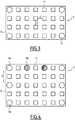
- a multi-sensor support panel 6has a rectangular shape, and comprises, on the radiating surface 8, an array of radiating elements 10 of square shape, arranged in a regular periodic pattern, two radiating elements 10 being spaced apart. a distance d of ⁇ / 2, where ⁇ is the wavelength corresponding to the radiation of the antenna 6 formed by the array of radiating elements 10.
- radiating elements 10 located at the corners of the rectangular radiating surfaceare replaced by optical sensors 16, according to a first mode of distribution of said optical sensors.
- the optical sensors 16are photographic sensors, of the CCD (for “charge coupled device”) or CMOS (for “Complementary Metal Oxide Semiconductor”) type, for example, capable of operating either in the field of visible radiation. , or in the infrared range.
- CCDcharge coupled device
- CMOScomplementary Metal Oxide Semiconductor
- Each such photographic sensoris capable of acquiring a digital image of approximately 10 megapixels.
- the optical sensors 16are positioned so as not to disturb the radiation pattern of the antenna.
- photographic sensors 16a capable of operating in the visible range and photographic sensors 16b capable of operating in the infrared rangeare positioned on the edges of the radiation surface 8, according to a second mode of distribution of the optical sensors.
- the positioningis incomplete, the minimum distance D between two photographic sensors being much greater than the distance d between two radiating elements 10, so as to preserve the antenna pattern of the antenna formed by the radiating elements 10.
- the antennais incomplete, and has minimal degradation.
- the photographic sensorsare positioned at various locations on the radiation surface 8, the distribution of the sensors 16a, 16b being performed in a pseudo-random manner, according to a third mode of distribution of the optical sensors.
- the type 16a sensors and the type 16b sensorsare offset with respect to the radiation surface 8, as illustrated schematically on figure 6 .
- the sensors 16aare positioned in a first reference plane P 1
- the sensors 16bare positioned in a second reference plane P 2 , the two reference planes P 1 and P 2 being offset.
- the reference plane offsetis applied for various sensors chosen, regardless of their type, some of the sensors 16a, 16b being located in the first reference plane P 1 , other sensors 16a, 16b being located in the second reference plane P 2 .
- the collected image datawill make it possible, thanks to the shift between the first reference plane and the second reference plane, to reconstruct a three-dimensional image, or 3D image, of the captured scene.
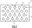
- a multi-sensor support panel 18comprises optical sensors 20 are made using optical fibers making it possible to transport the optical radiation picked up to optical receivers remote from the radiation surface 8. Such a operation is analogous to the operation of cameras used in endoscopy.
- the optical sensors 20are positioned on the radiation surface 8 according to a regular distribution pattern, interlaced with the radiating elements 22, according to a fourth distribution mode.
- the radiating elementsare square in shape, staggered.
- the distribution of the optical sensorsrespects a non-regular radiating element gap and a maximum gap value, said radiating elements being spaced apart by a half. wave length.
- the multi-sensor device 4also comprises a radiofrequency receiver 24, connected at the output of the multi-sensor support 4, for shaping the radiofrequency signals received by the antenna network.
- the radiofrequency receiver 24carries out amplification, filtering and multiplication by means of a mixer to obtain signals at intermediate frequency or in base band at output.
- the multi-sensor device 4also comprises a set 26 of optical receivers of the CCD or CMOS type, capable of transforming the electromagnetic radiation picked up by the sensors 20 into an electrical signal called an image signal.
- the receiver assembly 22is not present.
- radiofrequency signals and image signalsare obtained which are transmitted to a computing device 30, comprising one or more processors and memory units for storing data.
- the computing device 30comprises a radar processing module 32 and an image processing module 34.
- the computing device 30also comprises an operator interface 36, allowing an operator to control the processing operations to be performed, to view images of interest, and to focus on various planes of the image data obtained.
- the module 32receives signals in intermediate frequency or in base band from the radiofrequency reception module 24, and sends control commands to this radiofrequency reception module 24, and performs radar processing functions, for example the extraction of the distance and speed of a detected target.
- the speed and distance extractionis performed for each target.
- the radar processing module 32transmits first control information, relating to the target (s) detected, to the image processing module 34, and is also able to receive second control information coming from the image processing module. 34.
- the radar processing module 32is able, in one embodiment, to produce digital images of SAR types, and to transmit them to the image processing module 34 for comparison.
- the image processing module 34is able to merge the image signals from the different optical sensors to generate a super-resolved digital image.
- the image processing module 34is able to extract at least one sub-image located in the over-resolved digital image, as a function of the first control information supplied by the processing module. radar processing.
- the image processing module 34performs a zoom function on multiple zones, guided by one of the radar modes such as the detection of moving or fixed targets.
- the digital images obtained by the optical sensorsare advantageously stabilized image by image, using the first radar control information.
- the image processing module 34also performs checks making it possible to transmit second control information to the radar processing module 32.
- the image data contained in the captured digital imagesare used to carry out identifications of areas of interest by image processing, according to methods known in the field of image processing. Then, the identified areas of interest are transformed into second control information making it possible to focus the target detection by radar in an improved manner.
- the cooperative use of the radar processing module 32 and of the image processing module 34makes it possible to significantly reduce the data flows of an image of interest I, supplied at the output of the imaging device 1, at the request of an operator via the operator interface 36 or at the request of an external client application.
- the amount of image data for storage and transmission over communication networksis reduced.
- the cooperation between the radar processing 32 and image processing 34 modulesalso allows other functionalities, thanks to the harmonization between radar data and image data supplied by the optical sensors.
Landscapes
- Engineering & Computer Science (AREA)
- Remote Sensing (AREA)
- Radar, Positioning & Navigation (AREA)
- Physics & Mathematics (AREA)
- General Physics & Mathematics (AREA)
- Computer Networks & Wireless Communication (AREA)
- Aviation & Aerospace Engineering (AREA)
- Electromagnetism (AREA)
- Astronomy & Astrophysics (AREA)
- Radar Systems Or Details Thereof (AREA)
Description
Translated fromFrenchLa présente invention concerne un dispositif d'imagerie apte à être embarqué sur un porteur mobile.The present invention relates to an imaging device capable of being carried on board a mobile carrier.
L'invention se situe dans le domaine de l'imagerie multi-senseurs, trouvant de nombreuses applications dans les domaines de l'aéronautique, du ferroviaire, et des transports terrestre et naval.The invention lies in the field of multi-sensor imaging, finding numerous applications in the fields of aeronautics, railways, and land and naval transport.
En particulier, l'invention trouve des applications dans les domaines de la surveillance, de détection et d'évitement (en anglais « sense-and-avoid ») dans le domaine de l'aéronautique civile ou militaire, de désignation de zones d'intérêt, d'assistance automatique à l'atterrissage.In particular, the invention finds applications in the fields of surveillance, detection and avoidance (in English "sense-and-avoid") in the field of civil or military aeronautics, designation of zones of interest, automatic landing assistance.
Dans ces divers domaines, il est connu d'équiper un porteur mobile, par exemple un aéronef, de plusieurs systèmes de capture, à la fois d'un système radiofréquence apte à réaliser des fonctions de détection et de surveillance radar, et d'un système optronique apte à fournir des images numériques de scènes ou d'objets surveillés.In these various fields, it is known to equip a mobile carrier, for example an aircraft, with several capture systems, both with a radiofrequency system capable of performing radar detection and surveillance functions, and with a optronic system capable of providing digital images of scenes or monitored objects.
De manière classique, le porteur mobile est équipé de deux ou plusieurs tels systèmes distincts, situés à des endroits distincts. Par exemple, le porteur mobile est équipé d'un système radiofréquence radar multimodes, incluant des modes d'acquisition d'images (SAR pour « synthetic aperture radar », ISAR pour »inverse synthetic aperture radar ») et des modes de détection de cible (GMTI pour « ground moving target indicator ») et d'un système optronique ayant des capacités dans le domaine du visible et/ou dans le domaine de l'infrarouge, fournissant des données élaborées de manière indépendante. En effet, les systèmes de capture des données étant distincts et indépendants, les portées et les angles de capture sont différents. La cadence des mesures effectuées par ces systèmes de capture ainsi que la complétude des mesures et la résolution angulaire diffèrent.Conventionally, the mobile carrier is equipped with two or more such distinct systems, located at different places. For example, the mobile carrier is equipped with a multimode radio frequency radar system, including image acquisition modes (SAR for "synthetic aperture radar", ISAR for "reverse synthetic aperture radar") and target detection modes. (GMTI for “ground moving target indicator”) and an optronic system with capabilities in the visible and / or infrared domain, providing independently developed data. Indeed, the data capture systems being distinct and independent, the ranges and angles of capture are different. The rate of measurements carried out by these capture systems as well as the completeness of the measurements and the angular resolution differ.
Par conséquent, un recalage spatial et/ou temporel des données d'image est nécessaire pour fusionner les données d'image obtenues dans un référentiel commun.Therefore, a spatial and / or temporal registration of the image data is necessary to merge the image data obtained in a common repository.
La demande de brevet
Le document
Le document
Il existe un besoin de remédier aux inconvénients de l'état de la technique pour aboutir à une meilleure exploitation des données fournies par des senseurs multiples.There is a need to remedy the drawbacks of the state of the art in order to achieve better use of the data supplied by multiple sensors.
A cet effet, suivant un premier aspect, l'invention propose un dispositif d'imagerie apte à être embarqué sur un porteur mobile. Ce dispositif d'imagerie comporte un panneau de support multi-senseurs comportant une surface de rayonnement comportant une pluralité d'éléments rayonnants formant un réseau antennaire, lesdits éléments rayonnants étant associés à un module radiofréquence permettant de réaliser une fonction radar, et une pluralité de senseurs optiques positionnés sur ledit panneau de support multi-senseurs et répartis entre les éléments rayonnants selon un mode de répartition prédéterminé, lesdits senseurs optiques étant aptes à fournir des images numériques.To this end, according to a first aspect, the invention proposes an imaging device capable of being carried on board a mobile carrier. This imaging device comprises a multi-sensor support panel comprising a radiation surface comprising a plurality of radiating elements forming an antenna array, said radiating elements being associated with a radiofrequency module making it possible to perform a radar function, and a plurality of radiating elements. optical sensors positioned on said multi-sensor support panel and distributed among the radiating elements according to a predetermined distribution mode, said optical sensors being able to supply digital images.
Les senseurs optiques sont des capteurs photographiques parmi un premier type de capteurs photographiques aptes à fonctionner dans le domaine des ondes électromagnétiques visibles et un deuxième type de capteurs photographiques aptes à fonctionner dans le domaine des ondes électromagnétiques du domaine infrarouge.Optical sensors are photographic sensors among a first type of photographic sensors capable of operating in the field of visible electromagnetic waves and a second type of photographic sensors capable of operating in the field of electromagnetic waves of the infrared domain.
Au moins certains des capteurs photographiques de premier type sont positionnés dans un premier plan de référence, et au moins certain des capteurs photographiques de deuxième type sont positionnés dans un deuxième plan de référence décalé par rapport au premier plan de référence.At least some of the first type photographic sensors are positioned in a first reference plane, and at least some of the second type photographic sensors are positioned in a second reference plane offset from the first reference plane.
Le dispositif d'imagerie selon l'invention permet avantageusement, grâce à l'intégration sur un même panneau multi-senseurs, de bénéficier des données fournies par plusieurs types de senseurs qui ont des champs de capture naturellement co-localisés, donc aucun recalage n'est requis.The imaging device according to the invention advantageously makes it possible, thanks to the integration on the same multi-sensor panel, to benefit from the data supplied by several types of sensors which have naturally co-located capture fields, therefore no registration is necessary. 'is required.
Dans des modes de réalisation, le dispositif d'imagerie suivant l'invention comporte en outre une ou plusieurs des caractéristiques selon les revendications dépendantes.In embodiments, the imaging device according to the invention further comprises one or more of the features according to the dependent claims.
Des caractéristiques et avantages de l'invention ressortiront de la description qui en est donnée ci-dessous, à titre indicatif et nullement limitatif, en référence aux figures annexées, parmi lesquelles :
- la
figure 1 représente schématiquement un synoptique d'un dispositif d'imagerie selon un mode de réalisation de l'invention ; - la
figure 2 représente schématiquement un panneau multi-senseurs selon un mode de réalisation de l'invention ; - la
figure 3 représente schématiquement, en vue de dessus, un premier mode de réalisation d'un panneau multi-senseurs selon l'invention ; - la
figure 4 représente schématiquement, en vue de dessus, un deuxième mode de réalisation d'un panneau multi-senseurs selon l'invention ; - la
figure 5 représente schématiquement, en vue de dessus, un troisième mode de réalisation d'un panneau multi-senseurs selon l'invention ; - la
figure 6 représente schématiquement un décalage de plans de référence des capteurs ; - la
figure 7 représente schématiquement, en vue de dessus, un quatrième mode de réalisation d'un panneau multi-senseurs selon l'invention.
- the
figure 1 schematically represents a block diagram of an imaging device according to one embodiment of the invention; - the
figure 2 schematically represents a multi-sensor panel according to one embodiment of the invention; - the
figure 3 schematically shows, in top view, a first embodiment of a multi-sensor panel according to the invention; - the
figure 4 schematically shows, in top view, a second embodiment of a multi-sensor panel according to the invention; - the
figure 5 schematically shows, in top view, a third embodiment of a multi-sensor panel according to the invention; - the
figure 6 schematically represents an offset of the reference planes of the sensors; - the
figure 7 schematically shows, in top view, a fourth embodiment of a multi-sensor panel according to the invention.
La
Le dispositif d'imagerie 1 comporte un dispositif multi-senseurs 2 comportant un panneau de support multi-senseurs 4 sur lequel sont intégrés d'une part des senseurs radiofréquence et des senseurs optiques, représentés dans divers modes de réalisation dans les figures suivantes 2 à 7.The imaging device 1 comprises a
Le panneau de support multi-senseurs 4 est, dans un mode de réalisation, une antenne planaire, apte à fonctionner en émission et en réception dans une bande de fréquence donnée, par exemple la bande X, de 8 GHz à 12 GHz, modifiée pour intégrer des senseurs optiques.The
Selon l'invention, des senseurs optiques sont avantageusement intégrés dans une telle antenne planaire afin de réaliser, de manière conjointe, un système radiofréquence permettant d'implémenter une fonction radar et un système optronique apte à fournir des images numériques.According to the invention, optical sensors are advantageously integrated in such a planar antenna in order to produce, jointly, a radiofrequency system making it possible to implement a radar function and an optronic system capable of supplying digital images.
Dans un mode de réalisation, illustré schématiquement à la
Selon divers modes de réalisation de l'invention, outre les éléments rayonnants 10 d'une antenne planaire connue, des senseurs optiques 16 sont positionnés sur la surface de rayonnement 8, afin d'obtenir conjointement des données d'image numérique et des données radar.According to various embodiments of the invention, in addition to the
Plusieurs modes de réalisation de l'invention sont envisagés.Several embodiments of the invention are envisioned.
Selon un premier mode de réalisation illustré à la
Dans le mode de réalisation illustré, des éléments rayonnants 10 situés aux coins de la surface de rayonnement rectangulaire sont remplacés par des senseurs optiques 16, selon un premier mode de répartition desdits senseurs optiques.In the illustrated embodiment,
Dans ce mode de réalisation, les senseurs optiques 16 sont des capteurs photographiques, de type CCD (pour « charge coupled device ») ou CMOS (pour « Complementary Metal Oxide Semiconductor ») par exemple, aptes à fonctionner soit dans le domaine des rayonnements visibles, soit dans le domaine infrarouge.In this embodiment, the
Chaque tel capteur photographique est apte à faire l'acquisition d'une image numérique d'environ 10 mégapixels.Each such photographic sensor is capable of acquiring a digital image of approximately 10 megapixels.
Les senseurs optiques 16 sont positionnés de manière à ne pas perturber le diagramme de rayonnement de l'antenne.The
Dans un deuxième mode de réalisation, illustré à la
Le positionnement est lacunaire, la distance minimale D entre deux capteurs photographiques étant bien supérieure à la distance d entre deux éléments rayonnants 10, de manière à préserver le diagramme d'antenne de l'antenne formée par les éléments rayonnants 10.The positioning is incomplete, the minimum distance D between two photographic sensors being much greater than the distance d between two
Si moins de 10% des éléments rayonnants sont manquants, les manques ou trous étant non régulièrement répartis, l'antenne est lacunaire, et comporte des dégradations minimales.If less than 10% of the radiating elements are missing, the gaps or holes not being evenly distributed, the antenna is incomplete, and has minimal degradation.
Selon un troisième mode de réalisation illustré à la
De préférence, les capteurs de type 16a et les capteurs de type 16b sont décalés par rapport à la surface de rayonnement 8, comme illustré schématiquement à la
Les capteurs 16a sont positionnés dans un premier plan de référence P1, et les capteurs 16b sont positionnés dans un deuxième plan de référence P2, les deux plans de référence P1 et P2 étant en décalage.The
En variante, le décalage de plan de référence est appliqué pour divers capteurs choisis, indépendamment de leur type, certains des capteurs 16a, 16b étant situé dans le premier plan de référence P1, d'autres capteurs 16a, 16b étant situés dans le deuxième plan de référence P2.As a variant, the reference plane offset is applied for various sensors chosen, regardless of their type, some of the
Avantageusement, les données d'images collectées permettront, grâce au décalage entre le premier plan de référence et le deuxième plan de référence, de reconstruire une image à trois dimensions, ou image 3D, de la scène captée.Advantageously, the collected image data will make it possible, thanks to the shift between the first reference plane and the second reference plane, to reconstruct a three-dimensional image, or 3D image, of the captured scene.
Selon un quatrième mode de réalisation, un panneau de support multi-senseurs 18 comporte des senseurs optiques 20 sont réalisés en utilisant des fibres optiques permettant de transporter le rayonnement optique capté vers des récepteurs optiques déportés par rapport à la surface de rayonnement 8. Un tel fonctionnement est analogue au fonctionnement des caméras utilisées en endoscopie.According to a fourth embodiment, a
Dans ce mode de réalisation, les senseurs optiques 20 sont positionnés sur la surface de rayonnement 8 selon un motif de répartition régulier, entrelacés avec les éléments rayonnants 22, selon un quatrième mode de répartition.In this embodiment, the
Avantageusement dans ce mode de réalisation, il n'y a pas d'élément métallique conducteur positionné sur la surface de rayonnement 8, et donc pas de perturbation du diagramme d'antenne du réseau antennaire formé par les éléments rayonnants 22.Advantageously in this embodiment, there is no conductive metal element positioned on the
Dans le mode de réalisation illustré à la
Il est bien entendu que d'autres modes de réalisation sont envisageables, en ce qui concerne la forme des éléments rayonnants, leur positionnement et le motif de répétition sur la surface de rayonnement.Of course, other embodiments can be envisaged, as regards the shape of the radiating elements, their positioning and the repetition pattern on the radiating surface.
Par exemple, dans un mode de réalisation, qui peut être combiné avec les modes de réalisation précédemment décrits, la répartition des senseurs optiques respecte une lacunarité des éléments rayonnants non régulière et une valeur maximale de lacunarité, lesdits éléments rayonnants étant espacés d'une demi longueur d'onde.For example, in one embodiment, which can be combined with the previously described embodiments, the distribution of the optical sensors respects a non-regular radiating element gap and a maximum gap value, said radiating elements being spaced apart by a half. wave length.
De retour à la
Le récepteur radiofréquence 24 réalise une amplification, un filtrage et une multiplication au moyen d'un mélangeur pour obtenir en sortie des signaux en fréquence intermédiaire ou en bande de base.The
Dans le quatrième mode de réalisation de la
Dans les modes de réalisation dans lesquels des capteurs photographiques sont directement positionnés sur la surface de rayonnement 8, l'ensemble 22 de récepteurs n'est pas présent.In embodiments in which photographic sensors are directly positioned on the
Finalement en sortie du dispositif multi-senseurs 4 on obtient des signaux radiofréquence et des signaux d'image qui sont transmis à un dispositif de calcul 30, comprenant un ou plusieurs processeurs et des unités de mémoire pour le stockage de données.Finally, at the output of the
Le dispositif de calcul 30 comprend un module 32 de traitement radar et un module 34 de traitement d'images.The
Le dispositif de calcul 30 comprend également une interface opérateur 36, permettant à un opérateur de commander des traitements à effectuer, de visualiser des images d'intérêt, de focaliser sur divers plans des données d'images obtenues.The
Le module 32 reçoit des signaux en fréquence intermédiaire ou en bande de base du module de réception radiofréquence 24, et envoie des commandes de contrôle à ce module de réception radiofréquence 24, et réalise des fonctions de traitement radar, par exemple l'extraction de la distance et de la vitesse d'une cible détectée.The
Dans le cas où plusieurs cibles sont détectées, l'extraction de la vitesse et de la distance est effectuée pour chaque cible.In the event that multiple targets are detected, the speed and distance extraction is performed for each target.
Le module de traitement radar 32 transmet des premières informations de contrôle, relatives à la ou aux cibles détectées, au module de traitement d'image 34, et est également apte à recevoir des deuxièmes informations de contrôle en provenance du module de traitement d'image 34.The
En outre, le module de traitement radar 32 est apte, dans un mode de réalisation, à réaliser des images numériques de types SAR, et à les transmettre au module de traitement d'image 34 pour comparaison.In addition, the
Le module de traitement d'image 34 est apte à fusionner les signaux d'images issus des différents capteurs optiques pour générer une image numérique super-résolue.The
Grâce aux informations relatives à la ou aux cibles détectées le module de traitement d'image 34 est apte à extraire au moins une sous-image localisée dans l'image numérique sur-résolue, en fonction des premières informations de contrôle fournies par le module de traitement radar.Thanks to the information relating to the target (s) detected, the
Ainsi, le module de traitement d'image 34 réalise une fonction de zoom sur zones multiples, guidée par un des modes radar tels que la détection des cibles mobiles ou fixes.Thus, the
Les images numériques obtenues par les senseurs optiques sont avantageusement stabilisées image à image, en utilisant les premières informations de contrôle radar.The digital images obtained by the optical sensors are advantageously stabilized image by image, using the first radar control information.
En outre, le module de traitement d'images 34 effectue également des contrôles permettant de transmettre des deuxièmes informations de contrôle au module de traitement radar 32.In addition, the
Par exemple, les données d'image contenues dans les images numériques captées sont utilisées pour réaliser des identifications de zones d'intérêt par traitement d'image, selon des méthodes connues dans le domaine du traitement d'images. Ensuite, les zones d'intérêt identifiées sont transformées en deuxièmes informations de contrôle permettant de focaliser de manière améliorée la détection de cible par radar.For example, the image data contained in the captured digital images are used to carry out identifications of areas of interest by image processing, according to methods known in the field of image processing. Then, the identified areas of interest are transformed into second control information making it possible to focus the target detection by radar in an improved manner.
Lorsque les capteurs optiques sont positionnés de manière décalée entre un premier plan de référence P1 et un deuxième plan de référence P2 comme expliqué ci-dessus, il est possible de reconstruire des images 3D par traitement d'images, qui peuvent ensuite être utilisées pour lever des ambiguïtés dans les modes de surveillance du radar.When the optical sensors are positioned offset between a first reference plane P1 and a second reference plane P2 as explained above, it is possible to reconstruct 3D images by image processing, which can then be used. to resolve ambiguities in the radar surveillance modes.
Le décalage entre un premier plan de référence P1 et un deuxième plan de référence P2 comme expliqué ci-dessus s'applique pour tous les modes de réalisation du dispositif d'imagerie.The offset between a first reference plane P1 and a second reference plane P2 as explained above applies for all the embodiments of the imaging device.
Ainsi, l'utilisation coopérative du module de traitement radar 32 et du module de traitement d'image 34 permet de réduire de manière importante les flux de données d'une image d'intérêt I, fournie en sortie du dispositif d'imagerie 1, à la requête d'un opérateur via l'interface opérateur 36 ou à la requête d'une application cliente externe.Thus, the cooperative use of the
Avantageusement, la quantité de données d'image pour le stockage et la transmission sur des réseaux de communication est réduite.Advantageously, the amount of image data for storage and transmission over communication networks is reduced.
La coopération entre les modules de traitement radar 32 et de traitement d'image 34 permet également d'autres fonctionnalités, grâce à l'harmonisation entre données radar et données d'image fournies par les senseurs optiques.The cooperation between the
De plus, grâce à la co-localisation spatiale sur un même panneau de support multi-senseurs des senseurs radiofréquence et des senseurs optiques, aucun recalage n'est nécessaire pour l'exploitation des données captées.In addition, thanks to the spatial co-localization on the same multi-sensor support panel of the radiofrequency sensors and optical sensors, no registration is necessary for the use of the data collected.
Claims (12)
- Imaging device (1) capable of being mounted on a mobile carrier, comprising a multi-sensor support panel (4, 6, 18) having a radiation surface (8) having a plurality of radiating elements (10, 22) forming an antenna array, said radiating elements being associated with a radiofrequency module (24) allowing a radar function to be performed, and a plurality of optical sensors (16, 16a, 16b, 20) positioned on said multi-sensor support panel (4, 6, 18), said optical sensors (16, 16a, 16b, 20) being capable of providing digital images,characterised in that said optical sensors (16a, 16b) are distributed between the radiating elements in accordance with a predetermined distribution mode,in that said optical sensors are photographic sensors from among a first type of photographic sensors capable of functioning in the visible electromagnetic wave range and a second type of photographic sensors capable of functioning in the electromagnetic wave range of the infra-red range, andin that at least some of the photographic sensors (16a) of the first type are positioned in a first reference plane, andin that at least some of the photographic sensors (16b) of the second type are positioned in a second reference plane which is offset relative to the first reference plane.
- Imaging device according to claim 1,characterised in that the multi-sensor support panel (4, 6, 18) is rectangular, andin that the optical sensors (16, 16a, 16b) are positioned on at least one of the edges of the multi-sensor support panel.
- Imaging device according to either claim 1 or claim 2,characterised in that the optical sensors (16a, 16b) are positioned in accordance with a pseudo-random distribution.
- Imaging device according to claim 3,characterised in that two adjacent optical sensors of the same type are distant by a distance which is greater than a predetermined minimum distance.
- Imaging device according to any one of the preceding claims,characterised in that the distribution of the optical sensors respects a non-regular lacunarity of the radiating elements and a maximum lacunarity value, said radiating elements being spaced apart by a half wavelength.
- Imaging device according to any one of claims 1 to 5,characterised in that at least one optical sensor (16, 20) comprises an optical fibre end connected to an optical receiver positioned at a distance from the multi-sensor support panel (18).
- Imaging device according to claim 6,characterised in that it comprises a plurality of optical fibres, the optical sensors of which are distributed between the radiating elements in accordance with a regular distribution pattern.
- Imaging device according to any one of claims 1 to 7,characterised in that it comprises a computation device (30) comprising at least one processor, the computation device (30) comprising a radar processing module (32) for radiofrequency signals coming from said radiofrequency module and an image processing module (34) for digital image signals obtained, said radar processing module (32) and image processing module (34) being capable of cooperating.
- Imaging device according to claim 8,characterised in that the image processing module (34) is capable of forming an over-resolved digital image by fusion of the received image signals.
- Imaging device according to claim 9,characterised in that:- the radar processing module (32) is capable of locating at least one target and of transmitting first control information to the image processing module (34),- the image processing module (34) is capable of extracting at least one sub-image located in the over-resolved digital image, as a function of the first control information.
- Imaging device according to either claim 9 or claim 10,characterised in that the image processing module (34) is capable of performing a detection of zones of interest on the over-resolved digital image and of transmitting second control information to the radar processing module (32), allowing the radar processing module (32) to guide the radiofrequency module (24).
- Imaging device according to any one of claims 1 to 11,characterised in that, further, at least some of the photographic sensors (16a) of the first type are positioned in the second reference plane, and at least some of the photographic sensors (16b) of the second type are positioned in the first reference plane.
Applications Claiming Priority (2)
| Application Number | Priority Date | Filing Date | Title |
|---|---|---|---|
| FR1403046AFR3031193B1 (en) | 2014-12-30 | 2014-12-30 | MULTI-SENSOR IMAGING DEVICE |
| PCT/EP2015/081426WO2016107908A1 (en) | 2014-12-30 | 2015-12-30 | Multisensor imaging device |
Publications (2)
| Publication Number | Publication Date |
|---|---|
| EP3241039A1 EP3241039A1 (en) | 2017-11-08 |
| EP3241039B1true EP3241039B1 (en) | 2021-02-17 |
Family
ID=53059160
Family Applications (1)
| Application Number | Title | Priority Date | Filing Date |
|---|---|---|---|
| EP15817427.6AActiveEP3241039B1 (en) | 2014-12-30 | 2015-12-30 | Multisensor imaging device |
Country Status (3)
| Country | Link |
|---|---|
| EP (1) | EP3241039B1 (en) |
| FR (1) | FR3031193B1 (en) |
| WO (1) | WO2016107908A1 (en) |
Families Citing this family (3)
| Publication number | Priority date | Publication date | Assignee | Title |
|---|---|---|---|---|
| FR3064757A1 (en)* | 2017-03-29 | 2018-10-05 | Thales | CALIBRATION DEVICE OF IMAGING SYSTEM AND CALIBRATION METHOD THEREOF |
| IL257010B (en) | 2018-01-18 | 2021-10-31 | Israel Aerospace Ind Ltd | Camera-based automatic aircraft control for radar operation |
| CN116964738A (en)* | 2021-03-11 | 2023-10-27 | 索尼半导体解决方案公司 | Semiconductor device and electronic apparatus |
Citations (6)
| Publication number | Priority date | Publication date | Assignee | Title |
|---|---|---|---|---|
| US5436453A (en)* | 1993-10-15 | 1995-07-25 | Lockheed Sanders, Inc. | Dual mode energy detector having monolithic integrated circuit construction |
| US20030201929A1 (en)* | 2002-04-24 | 2003-10-30 | Lutter Robert Pierce Pierce | Multi-sensor system |
| US7358497B1 (en)* | 2005-04-08 | 2008-04-15 | University Of Central Florida Research Foundation, Inc. | Infrared/millimeter-wave focal plane array |
| US20110122012A1 (en)* | 2008-07-24 | 2011-05-26 | Koninklijke Philips Electronics N.V. | Distance measurement |
| US20140104095A1 (en)* | 2007-01-25 | 2014-04-17 | Magna Electronics Inc. | Forward facing sensing system for vehicle |
| EP2778711A1 (en)* | 2013-03-15 | 2014-09-17 | BAE Systems PLC | Directional multiband antenna |
Family Cites Families (5)
| Publication number | Priority date | Publication date | Assignee | Title |
|---|---|---|---|---|
| JPS60130274A (en)* | 1983-12-19 | 1985-07-11 | Toshiba Corp | solid-state imaging device |
| US4654622A (en)* | 1985-09-30 | 1987-03-31 | Honeywell Inc. | Monolithic integrated dual mode IR/mm-wave focal plane sensor |
| US6329649B1 (en)* | 1998-10-07 | 2001-12-11 | Raytheon Company | Mm-wave/IR monolithically integrated focal plane array |
| JP5624923B2 (en)* | 2011-03-23 | 2014-11-12 | 横河電子機器株式会社 | Intruder detection device |
| US8630805B2 (en) | 2011-10-20 | 2014-01-14 | Robert Bosch Gmbh | Methods and systems for creating maps with radar-optical imaging fusion |
- 2014
- 2014-12-30FRFR1403046Apatent/FR3031193B1/ennot_activeExpired - Fee Related
- 2015
- 2015-12-30WOPCT/EP2015/081426patent/WO2016107908A1/enactiveApplication Filing
- 2015-12-30EPEP15817427.6Apatent/EP3241039B1/enactiveActive
Patent Citations (6)
| Publication number | Priority date | Publication date | Assignee | Title |
|---|---|---|---|---|
| US5436453A (en)* | 1993-10-15 | 1995-07-25 | Lockheed Sanders, Inc. | Dual mode energy detector having monolithic integrated circuit construction |
| US20030201929A1 (en)* | 2002-04-24 | 2003-10-30 | Lutter Robert Pierce Pierce | Multi-sensor system |
| US7358497B1 (en)* | 2005-04-08 | 2008-04-15 | University Of Central Florida Research Foundation, Inc. | Infrared/millimeter-wave focal plane array |
| US20140104095A1 (en)* | 2007-01-25 | 2014-04-17 | Magna Electronics Inc. | Forward facing sensing system for vehicle |
| US20110122012A1 (en)* | 2008-07-24 | 2011-05-26 | Koninklijke Philips Electronics N.V. | Distance measurement |
| EP2778711A1 (en)* | 2013-03-15 | 2014-09-17 | BAE Systems PLC | Directional multiband antenna |
Also Published As
| Publication number | Publication date |
|---|---|
| FR3031193B1 (en) | 2018-08-17 |
| WO2016107908A1 (en) | 2016-07-07 |
| FR3031193A1 (en) | 2016-07-01 |
| EP3241039A1 (en) | 2017-11-08 |
Similar Documents
| Publication | Publication Date | Title |
|---|---|---|
| EP2734851B1 (en) | Calibration and testing device for an active antenna, particularly a nose-cone antenna of an airborne radar | |
| FR3064757A1 (en) | CALIBRATION DEVICE OF IMAGING SYSTEM AND CALIBRATION METHOD THEREOF | |
| CN108231094B (en) | Optical guidance system and method for correcting sensors using signals differentiated from each other | |
| EP2681585B1 (en) | Method for detecting and characterising a moving target on a radar image | |
| EP2469299B1 (en) | Method for enhancing images acquired by a radar with synthetic aperture | |
| EP3241039B1 (en) | Multisensor imaging device | |
| EP1982144B1 (en) | Method for geolocalization of one or more targets | |
| US10504206B2 (en) | Method and system for processing images from a remote image detector | |
| FR2950438A1 (en) | THREE-DIMENSIONAL LOCATION OF GROUND TARGET ZONE BY MERGING IMAGES TAKEN BY TWO SATELLITE SENSORS | |
| EP2642317B1 (en) | Device for receiving radio-navigation signals with multiple antennas | |
| EP0852734B1 (en) | Method and device for geodetic surveying and/or earth imaging by satellite signal processing | |
| US8754492B2 (en) | Sensor integrated slit for a pushbroom hyperspectral system | |
| EP3474037A1 (en) | Reconfigurable imaging device | |
| EP2388646B1 (en) | Method for capturing an image | |
| FR2988484A1 (en) | DEVICE FOR RECEIVING MULTI-ANTENNA RADIO NAVIGATION SIGNALS AND COMMON SYNCHRONIZATION SERVICING | |
| WO2018073371A1 (en) | Unmanned aerial vehicle operable by remote control, provided with imaging devices | |
| EP0778471B1 (en) | Radar detection method and system | |
| EP3165875B1 (en) | Method for acquiring images by a spaceborne or airborne optical instrument with extended field of view | |
| EP2574210B1 (en) | Altimetric measurement device | |
| EP4542250A1 (en) | Method for improving the performance of sensors in a system comprising a plurality of platforms each on board at least one sensor and an electronic processing module | |
| FR2923613A1 (en) | METHOD FOR REDUCING INTO BISTATIC SAR RADAR THE TRANSMISSION OF DATA BETWEEN CARRIERS BY FOCUSING TECHNIQUE ON TRANSMISSION | |
| WO2012117080A1 (en) | Method for positioning a moving element on a radar image | |
| FR2936382A1 (en) | DEVICE AND METHOD FOR ENUMERATION OF ELECTROMAGNETIC TRANSMITTERS | |
| FR2812143A1 (en) | Military GPS satellite positioning technique having multiple receive antennas with channel combiners producing channel frequency offset and signal combination processor. | |
| FR2944606A1 (en) | DEVICE FOR DETECTING OBJECTS, ESPECIALLY FITTED BY AN INDIVIDUAL. |
Legal Events
| Date | Code | Title | Description |
|---|---|---|---|
| STAA | Information on the status of an ep patent application or granted ep patent | Free format text:STATUS: THE INTERNATIONAL PUBLICATION HAS BEEN MADE | |
| PUAI | Public reference made under article 153(3) epc to a published international application that has entered the european phase | Free format text:ORIGINAL CODE: 0009012 | |
| STAA | Information on the status of an ep patent application or granted ep patent | Free format text:STATUS: REQUEST FOR EXAMINATION WAS MADE | |
| 17P | Request for examination filed | Effective date:20170627 | |
| AK | Designated contracting states | Kind code of ref document:A1 Designated state(s):AL AT BE BG CH CY CZ DE DK EE ES FI FR GB GR HR HU IE IS IT LI LT LU LV MC MK MT NL NO PL PT RO RS SE SI SK SM TR | |
| AX | Request for extension of the european patent | Extension state:BA ME | |
| DAV | Request for validation of the european patent (deleted) | ||
| DAX | Request for extension of the european patent (deleted) | ||
| STAA | Information on the status of an ep patent application or granted ep patent | Free format text:STATUS: EXAMINATION IS IN PROGRESS | |
| 17Q | First examination report despatched | Effective date:20190221 | |
| GRAP | Despatch of communication of intention to grant a patent | Free format text:ORIGINAL CODE: EPIDOSNIGR1 | |
| STAA | Information on the status of an ep patent application or granted ep patent | Free format text:STATUS: GRANT OF PATENT IS INTENDED | |
| INTG | Intention to grant announced | Effective date:20200929 | |
| GRAS | Grant fee paid | Free format text:ORIGINAL CODE: EPIDOSNIGR3 | |
| GRAA | (expected) grant | Free format text:ORIGINAL CODE: 0009210 | |
| STAA | Information on the status of an ep patent application or granted ep patent | Free format text:STATUS: THE PATENT HAS BEEN GRANTED | |
| AK | Designated contracting states | Kind code of ref document:B1 Designated state(s):AL AT BE BG CH CY CZ DE DK EE ES FI FR GB GR HR HU IE IS IT LI LT LU LV MC MK MT NL NO PL PT RO RS SE SI SK SM TR | |
| REG | Reference to a national code | Ref country code:GB Ref legal event code:FG4D Free format text:NOT ENGLISH | |
| REG | Reference to a national code | Ref country code:CH Ref legal event code:EP | |
| REG | Reference to a national code | Ref country code:DE Ref legal event code:R096 Ref document number:602015065718 Country of ref document:DE | |
| REG | Reference to a national code | Ref country code:AT Ref legal event code:REF Ref document number:1362169 Country of ref document:AT Kind code of ref document:T Effective date:20210315 | |
| REG | Reference to a national code | Ref country code:IE Ref legal event code:FG4D Free format text:LANGUAGE OF EP DOCUMENT: FRENCH | |
| REG | Reference to a national code | Ref country code:LT Ref legal event code:MG9D | |
| REG | Reference to a national code | Ref country code:NL Ref legal event code:MP Effective date:20210217 | |
| PG25 | Lapsed in a contracting state [announced via postgrant information from national office to epo] | Ref country code:BG Free format text:LAPSE BECAUSE OF FAILURE TO SUBMIT A TRANSLATION OF THE DESCRIPTION OR TO PAY THE FEE WITHIN THE PRESCRIBED TIME-LIMIT Effective date:20210517 Ref country code:FI Free format text:LAPSE BECAUSE OF FAILURE TO SUBMIT A TRANSLATION OF THE DESCRIPTION OR TO PAY THE FEE WITHIN THE PRESCRIBED TIME-LIMIT Effective date:20210217 Ref country code:HR Free format text:LAPSE BECAUSE OF FAILURE TO SUBMIT A TRANSLATION OF THE DESCRIPTION OR TO PAY THE FEE WITHIN THE PRESCRIBED TIME-LIMIT Effective date:20210217 Ref country code:GR Free format text:LAPSE BECAUSE OF FAILURE TO SUBMIT A TRANSLATION OF THE DESCRIPTION OR TO PAY THE FEE WITHIN THE PRESCRIBED TIME-LIMIT Effective date:20210518 Ref country code:NO Free format text:LAPSE BECAUSE OF FAILURE TO SUBMIT A TRANSLATION OF THE DESCRIPTION OR TO PAY THE FEE WITHIN THE PRESCRIBED TIME-LIMIT Effective date:20210517 Ref country code:PT Free format text:LAPSE BECAUSE OF FAILURE TO SUBMIT A TRANSLATION OF THE DESCRIPTION OR TO PAY THE FEE WITHIN THE PRESCRIBED TIME-LIMIT Effective date:20210617 Ref country code:LT Free format text:LAPSE BECAUSE OF FAILURE TO SUBMIT A TRANSLATION OF THE DESCRIPTION OR TO PAY THE FEE WITHIN THE PRESCRIBED TIME-LIMIT Effective date:20210217 | |
| REG | Reference to a national code | Ref country code:AT Ref legal event code:MK05 Ref document number:1362169 Country of ref document:AT Kind code of ref document:T Effective date:20210217 | |
| PG25 | Lapsed in a contracting state [announced via postgrant information from national office to epo] | Ref country code:SE Free format text:LAPSE BECAUSE OF FAILURE TO SUBMIT A TRANSLATION OF THE DESCRIPTION OR TO PAY THE FEE WITHIN THE PRESCRIBED TIME-LIMIT Effective date:20210217 Ref country code:PL Free format text:LAPSE BECAUSE OF FAILURE TO SUBMIT A TRANSLATION OF THE DESCRIPTION OR TO PAY THE FEE WITHIN THE PRESCRIBED TIME-LIMIT Effective date:20210217 Ref country code:LV Free format text:LAPSE BECAUSE OF FAILURE TO SUBMIT A TRANSLATION OF THE DESCRIPTION OR TO PAY THE FEE WITHIN THE PRESCRIBED TIME-LIMIT Effective date:20210217 Ref country code:NL Free format text:LAPSE BECAUSE OF FAILURE TO SUBMIT A TRANSLATION OF THE DESCRIPTION OR TO PAY THE FEE WITHIN THE PRESCRIBED TIME-LIMIT Effective date:20210217 Ref country code:RS Free format text:LAPSE BECAUSE OF FAILURE TO SUBMIT A TRANSLATION OF THE DESCRIPTION OR TO PAY THE FEE WITHIN THE PRESCRIBED TIME-LIMIT Effective date:20210217 | |
| PG25 | Lapsed in a contracting state [announced via postgrant information from national office to epo] | Ref country code:IS Free format text:LAPSE BECAUSE OF FAILURE TO SUBMIT A TRANSLATION OF THE DESCRIPTION OR TO PAY THE FEE WITHIN THE PRESCRIBED TIME-LIMIT Effective date:20210617 | |
| PG25 | Lapsed in a contracting state [announced via postgrant information from national office to epo] | Ref country code:SM Free format text:LAPSE BECAUSE OF FAILURE TO SUBMIT A TRANSLATION OF THE DESCRIPTION OR TO PAY THE FEE WITHIN THE PRESCRIBED TIME-LIMIT Effective date:20210217 Ref country code:AT Free format text:LAPSE BECAUSE OF FAILURE TO SUBMIT A TRANSLATION OF THE DESCRIPTION OR TO PAY THE FEE WITHIN THE PRESCRIBED TIME-LIMIT Effective date:20210217 Ref country code:EE Free format text:LAPSE BECAUSE OF FAILURE TO SUBMIT A TRANSLATION OF THE DESCRIPTION OR TO PAY THE FEE WITHIN THE PRESCRIBED TIME-LIMIT Effective date:20210217 Ref country code:CZ Free format text:LAPSE BECAUSE OF FAILURE TO SUBMIT A TRANSLATION OF THE DESCRIPTION OR TO PAY THE FEE WITHIN THE PRESCRIBED TIME-LIMIT Effective date:20210217 | |
| REG | Reference to a national code | Ref country code:DE Ref legal event code:R097 Ref document number:602015065718 Country of ref document:DE | |
| PG25 | Lapsed in a contracting state [announced via postgrant information from national office to epo] | Ref country code:DK Free format text:LAPSE BECAUSE OF FAILURE TO SUBMIT A TRANSLATION OF THE DESCRIPTION OR TO PAY THE FEE WITHIN THE PRESCRIBED TIME-LIMIT Effective date:20210217 Ref country code:SK Free format text:LAPSE BECAUSE OF FAILURE TO SUBMIT A TRANSLATION OF THE DESCRIPTION OR TO PAY THE FEE WITHIN THE PRESCRIBED TIME-LIMIT Effective date:20210217 Ref country code:RO Free format text:LAPSE BECAUSE OF FAILURE TO SUBMIT A TRANSLATION OF THE DESCRIPTION OR TO PAY THE FEE WITHIN THE PRESCRIBED TIME-LIMIT Effective date:20210217 | |
| PLBE | No opposition filed within time limit | Free format text:ORIGINAL CODE: 0009261 | |
| STAA | Information on the status of an ep patent application or granted ep patent | Free format text:STATUS: NO OPPOSITION FILED WITHIN TIME LIMIT | |
| 26N | No opposition filed | Effective date:20211118 | |
| PG25 | Lapsed in a contracting state [announced via postgrant information from national office to epo] | Ref country code:AL Free format text:LAPSE BECAUSE OF FAILURE TO SUBMIT A TRANSLATION OF THE DESCRIPTION OR TO PAY THE FEE WITHIN THE PRESCRIBED TIME-LIMIT Effective date:20210217 Ref country code:ES Free format text:LAPSE BECAUSE OF FAILURE TO SUBMIT A TRANSLATION OF THE DESCRIPTION OR TO PAY THE FEE WITHIN THE PRESCRIBED TIME-LIMIT Effective date:20210217 | |
| PG25 | Lapsed in a contracting state [announced via postgrant information from national office to epo] | Ref country code:SI Free format text:LAPSE BECAUSE OF FAILURE TO SUBMIT A TRANSLATION OF THE DESCRIPTION OR TO PAY THE FEE WITHIN THE PRESCRIBED TIME-LIMIT Effective date:20210217 | |
| PG25 | Lapsed in a contracting state [announced via postgrant information from national office to epo] | Ref country code:IS Free format text:LAPSE BECAUSE OF FAILURE TO SUBMIT A TRANSLATION OF THE DESCRIPTION OR TO PAY THE FEE WITHIN THE PRESCRIBED TIME-LIMIT Effective date:20210617 | |
| PG25 | Lapsed in a contracting state [announced via postgrant information from national office to epo] | Ref country code:MC Free format text:LAPSE BECAUSE OF FAILURE TO SUBMIT A TRANSLATION OF THE DESCRIPTION OR TO PAY THE FEE WITHIN THE PRESCRIBED TIME-LIMIT Effective date:20210217 | |
| REG | Reference to a national code | Ref country code:CH Ref legal event code:PL | |
| REG | Reference to a national code | Ref country code:BE Ref legal event code:MM Effective date:20211231 | |
| PG25 | Lapsed in a contracting state [announced via postgrant information from national office to epo] | Ref country code:LU Free format text:LAPSE BECAUSE OF NON-PAYMENT OF DUE FEES Effective date:20211230 Ref country code:IE Free format text:LAPSE BECAUSE OF NON-PAYMENT OF DUE FEES Effective date:20211230 | |
| PG25 | Lapsed in a contracting state [announced via postgrant information from national office to epo] | Ref country code:BE Free format text:LAPSE BECAUSE OF NON-PAYMENT OF DUE FEES Effective date:20211231 | |
| PG25 | Lapsed in a contracting state [announced via postgrant information from national office to epo] | Ref country code:LI Free format text:LAPSE BECAUSE OF NON-PAYMENT OF DUE FEES Effective date:20211231 Ref country code:CH Free format text:LAPSE BECAUSE OF NON-PAYMENT OF DUE FEES Effective date:20211231 | |
| PG25 | Lapsed in a contracting state [announced via postgrant information from national office to epo] | Ref country code:IT Free format text:LAPSE BECAUSE OF NON-PAYMENT OF DUE FEES Effective date:20211230 | |
| PG25 | Lapsed in a contracting state [announced via postgrant information from national office to epo] | Ref country code:HU Free format text:LAPSE BECAUSE OF FAILURE TO SUBMIT A TRANSLATION OF THE DESCRIPTION OR TO PAY THE FEE WITHIN THE PRESCRIBED TIME-LIMIT; INVALID AB INITIO Effective date:20151230 | |
| P01 | Opt-out of the competence of the unified patent court (upc) registered | Effective date:20230502 | |
| PG25 | Lapsed in a contracting state [announced via postgrant information from national office to epo] | Ref country code:CY Free format text:LAPSE BECAUSE OF FAILURE TO SUBMIT A TRANSLATION OF THE DESCRIPTION OR TO PAY THE FEE WITHIN THE PRESCRIBED TIME-LIMIT Effective date:20210217 | |
| PG25 | Lapsed in a contracting state [announced via postgrant information from national office to epo] | Ref country code:MK Free format text:LAPSE BECAUSE OF FAILURE TO SUBMIT A TRANSLATION OF THE DESCRIPTION OR TO PAY THE FEE WITHIN THE PRESCRIBED TIME-LIMIT Effective date:20210217 | |
| PG25 | Lapsed in a contracting state [announced via postgrant information from national office to epo] | Ref country code:MT Free format text:LAPSE BECAUSE OF FAILURE TO SUBMIT A TRANSLATION OF THE DESCRIPTION OR TO PAY THE FEE WITHIN THE PRESCRIBED TIME-LIMIT Effective date:20210217 | |
| PGFP | Annual fee paid to national office [announced via postgrant information from national office to epo] | Ref country code:DE Payment date:20241211 Year of fee payment:10 | |
| PGFP | Annual fee paid to national office [announced via postgrant information from national office to epo] | Ref country code:GB Payment date:20241219 Year of fee payment:10 | |
| PGFP | Annual fee paid to national office [announced via postgrant information from national office to epo] | Ref country code:FR Payment date:20241224 Year of fee payment:10 |