EP3239804B1 - Control of an electronic device including display and keyboard moveable relative to the display - Google Patents
Control of an electronic device including display and keyboard moveable relative to the displayDownload PDFInfo
- Publication number
- EP3239804B1 EP3239804B1EP17162040.4AEP17162040AEP3239804B1EP 3239804 B1EP3239804 B1EP 3239804B1EP 17162040 AEP17162040 AEP 17162040AEP 3239804 B1EP3239804 B1EP 3239804B1
- Authority
- EP
- European Patent Office
- Prior art keywords
- keyboard
- display
- touch
- electronic device
- relative
- Prior art date
- Legal status (The legal status is an assumption and is not a legal conclusion. Google has not performed a legal analysis and makes no representation as to the accuracy of the status listed.)
- Active
Links
Images


Classifications
- G—PHYSICS
- G06—COMPUTING OR CALCULATING; COUNTING
- G06F—ELECTRIC DIGITAL DATA PROCESSING
- G06F3/00—Input arrangements for transferring data to be processed into a form capable of being handled by the computer; Output arrangements for transferring data from processing unit to output unit, e.g. interface arrangements
- G06F3/01—Input arrangements or combined input and output arrangements for interaction between user and computer
- G06F3/048—Interaction techniques based on graphical user interfaces [GUI]
- G06F3/0484—Interaction techniques based on graphical user interfaces [GUI] for the control of specific functions or operations, e.g. selecting or manipulating an object, an image or a displayed text element, setting a parameter value or selecting a range
- G06F3/04847—Interaction techniques to control parameter settings, e.g. interaction with sliders or dials
- G—PHYSICS
- G06—COMPUTING OR CALCULATING; COUNTING
- G06F—ELECTRIC DIGITAL DATA PROCESSING
- G06F1/00—Details not covered by groups G06F3/00 - G06F13/00 and G06F21/00
- G06F1/16—Constructional details or arrangements
- G06F1/1613—Constructional details or arrangements for portable computers
- G06F1/1615—Constructional details or arrangements for portable computers with several enclosures having relative motions, each enclosure supporting at least one I/O or computing function
- G06F1/1624—Constructional details or arrangements for portable computers with several enclosures having relative motions, each enclosure supporting at least one I/O or computing function with sliding enclosures, e.g. sliding keyboard or display
- G—PHYSICS
- G06—COMPUTING OR CALCULATING; COUNTING
- G06F—ELECTRIC DIGITAL DATA PROCESSING
- G06F1/00—Details not covered by groups G06F3/00 - G06F13/00 and G06F21/00
- G06F1/16—Constructional details or arrangements
- G06F1/1613—Constructional details or arrangements for portable computers
- G06F1/1633—Constructional details or arrangements of portable computers not specific to the type of enclosures covered by groups G06F1/1615 - G06F1/1626
- G06F1/1662—Details related to the integrated keyboard
- G06F1/1666—Arrangements for reducing the size of the integrated keyboard for transport, e.g. foldable keyboards, keyboards with collapsible keys
- G—PHYSICS
- G06—COMPUTING OR CALCULATING; COUNTING
- G06F—ELECTRIC DIGITAL DATA PROCESSING
- G06F1/00—Details not covered by groups G06F3/00 - G06F13/00 and G06F21/00
- G06F1/16—Constructional details or arrangements
- G06F1/1613—Constructional details or arrangements for portable computers
- G06F1/1633—Constructional details or arrangements of portable computers not specific to the type of enclosures covered by groups G06F1/1615 - G06F1/1626
- G06F1/1675—Miscellaneous details related to the relative movement between the different enclosures or enclosure parts
- G06F1/1677—Miscellaneous details related to the relative movement between the different enclosures or enclosure parts for detecting open or closed state or particular intermediate positions assumed by movable parts of the enclosure, e.g. detection of display lid position with respect to main body in a laptop, detection of opening of the cover of battery compartment
- G—PHYSICS
- G06—COMPUTING OR CALCULATING; COUNTING
- G06F—ELECTRIC DIGITAL DATA PROCESSING
- G06F3/00—Input arrangements for transferring data to be processed into a form capable of being handled by the computer; Output arrangements for transferring data from processing unit to output unit, e.g. interface arrangements
- G06F3/01—Input arrangements or combined input and output arrangements for interaction between user and computer
- G06F3/03—Arrangements for converting the position or the displacement of a member into a coded form
- G06F3/033—Pointing devices displaced or positioned by the user, e.g. mice, trackballs, pens or joysticks; Accessories therefor
- G06F3/0338—Pointing devices displaced or positioned by the user, e.g. mice, trackballs, pens or joysticks; Accessories therefor with detection of limited linear or angular displacement of an operating part of the device from a neutral position, e.g. isotonic or isometric joysticks
- G—PHYSICS
- G06—COMPUTING OR CALCULATING; COUNTING
- G06F—ELECTRIC DIGITAL DATA PROCESSING
- G06F3/00—Input arrangements for transferring data to be processed into a form capable of being handled by the computer; Output arrangements for transferring data from processing unit to output unit, e.g. interface arrangements
- G06F3/01—Input arrangements or combined input and output arrangements for interaction between user and computer
- G06F3/048—Interaction techniques based on graphical user interfaces [GUI]
- G06F3/0487—Interaction techniques based on graphical user interfaces [GUI] using specific features provided by the input device, e.g. functions controlled by the rotation of a mouse with dual sensing arrangements, or of the nature of the input device, e.g. tap gestures based on pressure sensed by a digitiser
- G06F3/0488—Interaction techniques based on graphical user interfaces [GUI] using specific features provided by the input device, e.g. functions controlled by the rotation of a mouse with dual sensing arrangements, or of the nature of the input device, e.g. tap gestures based on pressure sensed by a digitiser using a touch-screen or digitiser, e.g. input of commands through traced gestures
- G06F3/04883—Interaction techniques based on graphical user interfaces [GUI] using specific features provided by the input device, e.g. functions controlled by the rotation of a mouse with dual sensing arrangements, or of the nature of the input device, e.g. tap gestures based on pressure sensed by a digitiser using a touch-screen or digitiser, e.g. input of commands through traced gestures for inputting data by handwriting, e.g. gesture or text
- G—PHYSICS
- G06—COMPUTING OR CALCULATING; COUNTING
- G06F—ELECTRIC DIGITAL DATA PROCESSING
- G06F3/00—Input arrangements for transferring data to be processed into a form capable of being handled by the computer; Output arrangements for transferring data from processing unit to output unit, e.g. interface arrangements
- G06F3/16—Sound input; Sound output
- G06F3/165—Management of the audio stream, e.g. setting of volume, audio stream path
- H—ELECTRICITY
- H04—ELECTRIC COMMUNICATION TECHNIQUE
- H04M—TELEPHONIC COMMUNICATION
- H04M1/00—Substation equipment, e.g. for use by subscribers
- H04M1/02—Constructional features of telephone sets
- H04M1/0202—Portable telephone sets, e.g. cordless phones, mobile phones or bar type handsets
- H04M1/0206—Portable telephones comprising a plurality of mechanically joined movable body parts, e.g. hinged housings
- H04M1/0208—Portable telephones comprising a plurality of mechanically joined movable body parts, e.g. hinged housings characterized by the relative motions of the body parts
- H04M1/0235—Slidable or telescopic telephones, i.e. with a relative translation movement of the body parts; Telephones using a combination of translation and other relative motions of the body parts
- H04M1/0237—Sliding mechanism with one degree of freedom
- H—ELECTRICITY
- H04—ELECTRIC COMMUNICATION TECHNIQUE
- H04M—TELEPHONIC COMMUNICATION
- H04M1/00—Substation equipment, e.g. for use by subscribers
- H04M1/02—Constructional features of telephone sets
- H04M1/0202—Portable telephone sets, e.g. cordless phones, mobile phones or bar type handsets
- H04M1/0206—Portable telephones comprising a plurality of mechanically joined movable body parts, e.g. hinged housings
- H04M1/0241—Portable telephones comprising a plurality of mechanically joined movable body parts, e.g. hinged housings using relative motion of the body parts to change the operational status of the telephone set, e.g. switching on/off, answering incoming call
- H—ELECTRICITY
- H04—ELECTRIC COMMUNICATION TECHNIQUE
- H04M—TELEPHONIC COMMUNICATION
- H04M1/00—Substation equipment, e.g. for use by subscribers
- H04M1/02—Constructional features of telephone sets
- H04M1/23—Construction or mounting of dials or of equivalent devices; Means for facilitating the use thereof
- H—ELECTRICITY
- H04—ELECTRIC COMMUNICATION TECHNIQUE
- H04M—TELEPHONIC COMMUNICATION
- H04M2250/00—Details of telephonic subscriber devices
- H04M2250/22—Details of telephonic subscriber devices including a touch pad, a touch sensor or a touch detector
Definitions
- the present disclosurerelates to an electronic device including a display and a keyboard that is moveable relative to the display and to the control of such an electronic device.
- Portable electronic devicesinclude several types of devices including mobile stations such as simple cellular telephones, smart telephones (smart phones), Personal Digital Assistants (PDAs), and tablet computers with wireless network communications or near-field communications connectivity such as Bluetooth® capabilities.
- mobile stationssuch as simple cellular telephones, smart telephones (smart phones), Personal Digital Assistants (PDAs), and tablet computers with wireless network communications or near-field communications connectivity such as Bluetooth® capabilities.
- PDAsPersonal Digital Assistants
- tablet computerswith wireless network communications or near-field communications connectivity such as Bluetooth® capabilities.
- Portable electronic devicessuch as PDAs, or tablet computers are generally intended for handheld use and ease of portability.
- Displays that are moveable relative to a keyboard, from a position in which the keyboard is hidden to a position in which the keyboard is exposed for useare particularly useful on portable electronic devices, which are small and may have limited space for user input and output.
- US 2011/0053650 A1discloses a mobile terminal and display controlling method that includes detecting whether the position of the keypad is shifted to cover a partial display region of the display unit, if it is detected that the position of the keypad is shifted, changing a normal display mode into a control display mode, and if the control display mode is entered, performing a display operation corresponding to the control display mode in a different display region except the partial display region. Accordingly, in case that a keypad is located to cover a display region of a display unit in part, the present invention enables a display function to be effectively performed in the rest of the display region except the partially covered display region.
- the followingdescribes an electronic device including a keyboard and a display moveable relative to the keyboard, between a first position in which the keyboard is exposed for use and a second position in which the keyboard is not exposed, and a method of controlling the electronic device.
- the methodincludes, in response to detecting initiation of control of a position of an adjustable setting within a range, entering a control mode at the electronic device, and, in response to detecting movement of the display relative to the keyboard of the electronic device, adjusting the position of the adjustable setting within the range.
- the disclosuregenerally relates to an electronic device, such as a portable electronic device.
- portable electronic devicesinclude mobile, or handheld, wireless communication devices such as pagers, cellular phones, cellular smart-phones, wireless organizers, personal digital assistants, wirelessly enabled notebook computers, tablet computers, mobile internet devices, electronic navigation devices, and so forth.
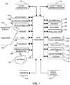
- FIG. 1A block diagram of an example of an electronic device 100 is shown in FIG. 1 .
- the electronic device 100includes multiple components, such as a processor 102 that controls the overall operation of the electronic device 100. Communication functions, including data and voice communications, are performed through a communication subsystem 104. Data received by the electronic device 100 is decompressed and decrypted by a decoder 106. The communication subsystem 104 receives messages from and sends messages to a wireless network 150.
- the wireless network 150may be any type of wireless network, including, but not limited to, data wireless networks, voice wireless networks, and networks that support both voice and data communications.
- a power source 142such as one or more rechargeable batteries or a port to an external power supply, powers the electronic device 100.
- the processor 102interacts with other components, such as a Random Access Memory (RAM) 108, memory 110, a touch-sensitive display 118, a physical keyboard 120, an auxiliary input/output (I/O) subsystem 124, a data port 126, a speaker 128, a microphone 130, short-range communications 132 and other device subsystems 134.
- the touch-sensitive display 118includes a display 112 and touch sensors 114 that are coupled to at least one controller 116 that is utilized to interact with the processor 102. Input via a graphical user interface is provided via the touch-sensitive display 118. Thus, the touch sensors 114 and the controller 116 are utilized as an input device.
- the keyboardmay be, for example, a physical keyboard 120 that includes a plurality of mechanical keys that have mechanical switches or contacts for input to the electronic device 100 when a mechanical key of the keyboard is depressed by a sufficient force to oppose a bias of the mechanical key.
- touch sensors 122are disposed on the physical keyboard 120 and the touch sensors 122 are coupled to a controller 123.
- the touch-sensitive display 118is moveable relative to the physical keyboard 120.
- a keyboard sensor 138is utilized to detect a location of the touch-sensitive display 118 relative to the physical keyboard 120 of the electronic device 100.
- the processor 102may also interact with an accelerometer 136 that may be utilized to detect direction of gravitational forces or gravity-induced reaction forces.
- the electronic device 100may utilize a Subscriber Identity Module or a Removable User Identity Module (SIM/RUIM) card 144 for communication with a network, such as the wireless network 150.
- SIM/RUIMRemovable User Identity Module
- user identification informationmay be programmed into memory 110.
- the electronic device 100includes an operating system 146 and software programs, applications, or components 148 that are executed by the processor 102 and are typically stored in a persistent, updatable store such as the memory 110. Additional applications or programs may be loaded onto the electronic device 100 through the wireless network 150, the auxiliary I/O subsystem 124, the data port 126, the short-range communications subsystem 132, or any other suitable subsystem 134.
- a received signalsuch as a text message, an e-mail message, or web page download is processed by the communication subsystem 104 and input to the processor 102.
- the processor 102processes the received signal for output to the display 112 and/or to the auxiliary I/O subsystem 124.
- a subscribermay generate data items, for example e-mail messages, which may be transmitted over the wireless network 150 through the communication subsystem 104.
- the speaker 128outputs audible information converted from electrical signals
- the microphone 130converts audible information into electrical signals for processing.
- the touch-sensitive display 118may be any suitable touch-sensitive display, such as a capacitive touch-sensitive display.
- a capacitive touch-sensitive displayincludes capacitive touch sensors 114.
- the capacitive touch sensorsmay comprise any suitable material, such as indium tin oxide (ITO).
- One or more touchesmay be detected by the touch-sensitive display 118.
- the processor 102may determine attributes of the touch, including a location of the touch.
- Touch location datamay include data for an area of contact or data for a single point of contact, such as a point at or near a center of the area of contact.
- the location of a detected touchmay include x and y components, e.g., horizontal and vertical components, respectively, with respect to one's view of the touch-sensitive display 118.
- a touchmay be detected from any suitable input member, such as a finger, thumb, appendage, or other objects, for example, a stylus, pen, or other pointer, depending on the nature of the touch-sensitive display 118. Multiple simultaneous touches may be detected.
- a tapwhich is a particular type of touch may be a touch that ends within a threshold period of time.
- the touch contact with the touch-sensitive display 118is relatively short because contact ends within a threshold period of time of beginning.
- One or more gesturesmay also be detected by the touch-sensitive display 118.
- a gesturesuch as a swipe, also known as a flick, is a particular type of touch on a touch-sensitive display 118 and may begin at an origin point and continue to an end point, for example, a concluding end of the gesture.
- a gesturemay be identified by attributes of the gesture, including the origin point, the end point, the distance travelled, the duration, the velocity, and the direction, for example.
- a gesturemay be long or short in distance and/or duration. Two points of the gesture may be utilized to determine a direction of the gesture.
- a gesturemay also include a hover.
- a hovermay be a touch at a location that is generally unchanged over a period of time or is associated with the same selection item for a period of time.
- the touch sensors 122 on the physical keyboard 120may be any suitable touch sensors, such as capacitive touch-sensors and may comprise any suitable material, such as indium tin oxide (ITO).
- the touch sensors 122 disposed on the physical keyboard 120may be coupled to the same controller 116 as the touch sensors of touch-sensitive display 118 such that a single controller is utilized rather than two controllers 116, 123.
- One or more touches on the keys of the keyboard 120may be detected.
- the processor 102may determine attributes of the touch, including a location of the touch.
- Touch location datamay include data for an area of contact or data for a single point of contact, such as a point at or near a center of the area of contact.
- the location of a detected touchmay include x and y components, e.g., horizontal and vertical components, respectively, with respect to one's view of the keyboard 120.
- a touchmay be detected from any suitable input member and multiple simultaneous touches may be detected.
- One or more gesturesmay also be detected by the touch sensors 122 disposed on the keyboard 120.
- a gesture on the keys of the keyboard 120may be identified by attributes of the gesture, including the origin point, the end point, the distance travelled, the duration, the velocity, and the direction, for example.
- a gesturemay be long or short in distance and/or duration. Two points of the gesture may be utilized to determine a direction of the gesture.
- a gesturemay also include a hover.
- the touch-sensitive display 118includes a display area in which information may be displayed, and a non-display area extending around the periphery of the display area. Information is not displayed in the non-display area by the display, which non-display area is utilized to accommodate, for example, electronic traces or electrical connections, adhesives or other sealants, and/or protective coatings around the edges of the display area.
- the non-display areamay be referred to as an inactive area and is not part of the physical housing or frame of the electronic device. Typically, no pixels of the display are in the non-display area, thus no image is displayed by the display 112 in the non-display area.
- Touch sensorsmay be disposed in the non-display area, which touch sensors may be extended from the touch sensors in the display area or distinct or separate touch sensors from the touch sensors in the display area.
- a touch on the touch-sensitive display 118, including a gesture,may be associated with the display area, the non-display area, or both areas.
- the touch sensorsmay extend across substantially the entire non-display area or may be disposed in only part of the non-display area.
- FIG. 2A front view of an example of the electronic device 100 is shown in FIG. 2 .
- the electronic device 100includes a display housing 202 in which the touch-sensitive display 118 is disposed.
- the display housing 202is utilized to house or support components including at least some of the components shown in FIG. 1 .
- the physical keyboard 120is disposed in a keyboard housing 204, which is shown in FIG. 3 , below the touch-sensitive display 118 in the orientation illustrated in FIG. 3 .
- the physical keyboard 120includes a plurality of mechanical keys 206. Each one of the mechanical keys 206 of the keyboard is associated with characters or a function such that the characters are entered utilizing the mechanical keys 206.
- the keyboard housing 204may also be utilized to house or support components including at least some of the components shown in FIG. 1 .
- display housing 202is moveable relative to the keyboard housing 204 by sliding the display housing 202 between a first position in which the keyboard housing 204 is stacked with the display housing 202 such that the physical keyboard 120 is disposed between the display housing 202 and a back of the keyboard housing 204, as shown in FIG. 2 , and a second position in which the keyboard housing 204 extends from the display housing 202 to expose the physical keyboard 120 below the touch-sensitive display 118 in the orientation in which the portable electronic device 100 is illustrated in FIG. 3 .
- touch-sensitive display 118is moveable relative to the physical keyboard 120, between the first position, shown in FIG. 2 , in which the physical keyboard is not exposed and the second position, shown in FIG. 3 , in which the physical keyboard 120 is exposed for use.
- the physical keyboard 120is therefore selectively exposable for use.
- the keyboard sensor 138referred to above with reference to FIG. 1 , is arranged and constructed to detect a position of the display housing 202 relative to the keyboard housing 204.
- the keyboard sensor 138is coupled to the processor 102 to detect that the touch-sensitive display 118 is in the first position, the second position, or in a location between the first and the second positions.
- the processor 102 in connection with the keyboard sensor 138may detect the percentage that the physical keyboard 120 is exposed.
- the keyboard sensor 138together with the processor 102 detects movement of the touch-sensitive display 118 relative to the physical keyboard 120.
- the physical keyboard 120may be a QWERTY keyboard.
- other keyboard layoutsmay be successfully implemented, such as an AZERTY keyboard, a QWERTZ keyboard, or any other suitable keyboard.
- Informationmay be displayed on the touch-sensitive display 118.
- the information displayedmay include any suitable information such as icons, text, pictures, video, documents, a webpage, or any other suitable information.
- the informationmay be associated with, for example, a home page, a menu or submenu, an application or applications, and so forth.
- the informationmay be selectable, for example, by a touch on the touch-sensitive display 118, or by a touch, such as a hover gesture, a tap, a double tap, or other suitable touch, on the physical keyboard 120.
- a virtual keyboardmay also be displayed.
- the keys of the virtual keyboardmay be selectable by a touch on an area of the touch-sensitive display 118 associated with the respective key.
- Display of the virtual keyboardmay be discontinued in response to movement of the display housing 202 relative to the keyboard housing 204 to the second position, as shown in FIG.3 , to thereby expose the physical keyboard 120.
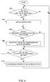
- FIG. 4A flowchart illustrating a method of controlling an electronic device that has a display moveable relative to the keyboard, such as the electronic device 100, is shown in FIG. 4 .
- the methodmay be carried out by software executed, for example, by a processor 102 in a portable electronic device 100. Coding of software for carrying out such a method is within the scope of a person of ordinary skill in the art given the present description.
- the methodmay contain additional or fewer processes than shown and/or described, and may be performed in a different order.
- Computer-readable code executable by at least one processor of the portable electronic device to perform the methodmay be stored in a computer-readable medium, such as a non-transitory computer-readable device.
- the method illustrated in FIG. 4may be carried out, for example, any time the portable electronic device 120 is on and is running the operating system or an application.
- Initiation of control of the adjustable settingmay be detected by detecting a touch at a location on the touch-sensitive display 118, for example.
- the locationmay include information displayed such as a graphical representation, a word or symbol, or any suitable identifier or information.
- the locationmay include a graphical representation of a button, thus providing a selectable button on the touch-sensitive display 118.
- the adjustable settingmay be, for example, a volume output such as volume of a notification, a brightness of the touch-sensitive display 118, or any other suitable setting.
- the adjustable settingmay be a playback position within a file in a media player.
- the adjustable settingmay be a position within a song or a position within a video.
- the adjustable settingmay be application dependent such that the adjustable setting may be identified based on the application running on the portable electronic device at the time the initiation of control is detected.
- the adjustable settingmay be identified from more than one adjustable setting in the group of adjustable settings.
- the adjustable settingmay be identified based on the location of the touch on the touch-sensitive display 118, for example.
- a volume controlmay be identified in response to detecting a touch at a first location associated with the volume and a video playback position may be identified in response to detecting a touch at a second location associated with the video.
- the control modeis entered at 404 and an initial position of the adjustable setting may optionally be adjusted based on the starting position of the touch-sensitive display 118 relative to the physical keyboard 120 when initiation of control of the adjustable setting is detected.
- an initial position of the adjustable settingmay optionally be adjusted based on the starting position of the touch-sensitive display 118 relative to the physical keyboard 120 when initiation of control of the adjustable setting is detected.
- a volume, brightness, or playback positionmay be initially adjusted based on the position of the touch-sensitive display 118 relative to the physical keyboard 120 at the time that initiation of control of the adjustable setting is detected.
- the processcontinues at 408.
- the movement of the touch-sensitive display 118 relative to the physical keyboard 120may be movement toward the first position in which the keyboard is not exposed or movement toward the second position in which the keyboard is exposed for use.
- the keyboard sensor 138is utilized to detect any movement of the touch-sensitive display 118 relative to the physical keyboard 120 after initiation of control of the adjustable setting. The percentage or extent that the physical keyboard 120 is exposed is detected and changes in the percentage or extent that the physical keyboard 120 is exposed by movement of the touch-sensitive display 118 are detected.
- a position of an adjustable setting within the rangeis adjusted based on the percentage or extent that the physical keyboard is exposed at 408.
- the position of the adjustable setting within the rangeis dependent on the location of the touch-sensitive display 118 relative to the physical keyboard 120 of the electronic device 100.
- a volume or a brightness levelmay be adjusted by a percentage increase that is generally equivalent to the percentage or extent that the touch-sensitive display 118 is moved within the range of movement of the touch-sensitive display 118 relative to the physical keyboard 120.
- a playback position of a video or audio filemay be changed by a percentage that is generally equivalent to the percentage or extent that the touch-sensitive display 118 is moved relative to the physical keyboard 120.
- the position of the adjustable settingmay be adjusted in either direction along with movement of the touch-sensitive display 118 relative to the physical keyboard 120.
- the control modeis exited and adjustment of the position of the adjustable setting within the range in response to detecting movement of the touch-sensitive display 118 relative to the physical keyboard 120 is discontinued at 412.
- the end of control of the position of the adjustable settingmay be detected, for example, when a touch, which may be a gesture or a touch on a key, is detected on the physical keyboard 120, or when a second touch is detected on the touch-sensitive display 118.
- the end of control of the position of the adjustable settingmay be detected by detecting a pause in the movement of the touch-sensitive display 118 relative to the physical keyboard 120 such that the relative movement of the touch-sensitive display 118 is stopped for a period of time that meets or exceeds a threshold period of time.
- the end of control of the position of the adjustable settingmay be detected when the electronic device 100 detects that a touch on the touch-sensitive display 118 is ended.
- a touch on the touch-sensitive display 118may be utilized to enter the control mode and the electronic device 100 remains in the control mode until the same touch on the touch-sensitive display 118 is ended.
- control of the position of the adjustable settingmay begin when the touch-sensitive display 118 is moved to a position relative to the physical keyboard 120 that generally matches the initial position of the adjustable setting at the time initiation of control is detected.
- the touch-sensitive display 118may be utilized to display a first marker or indicator illustrating the initial position of the adjustable setting within the range and a second marker or indicator may be displayed to illustrate the position of the touch-sensitive display 118 relative to the physical keyboard 120.
- the touch-sensitive display 118is then moved relative to the physical keyboard 120 and the second marker or indicator is moved along with movement of the touch-sensitive display 118, until the second marker or indicator is aligned with the first marker or indicator.
- control of the position of the adjustable settingbegins.
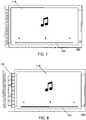
- a volume control button 502is displayed on the touch-sensitive display 118.
- the volume control buttonmay be displayed, for example, in response to launching or executing an application, or may be displayed as part of a home screen.
- the volume control buttonmay be a physical button in the display housing 202.
- the electronic device 100In response to detecting a touch illustrated by the circle 504 on the touch-sensitive display 118, at a location associated with the volume control button 502 at 402, the electronic device 100 enters a volume control mode and the initial position of the volume is adjusted at 404.
- the initial position of the volumeis adjusted based on the starting position of the touch-sensitive display 118 relative to the physical keyboard 120 when initiation of control of the adjustable setting is detected.
- the touch-sensitive display 118is in the second position such that the physical keyboard 120 is entirely exposed for use when initiation of the volume control mode is detected and the initial position of the volume is adjusted to a maximum or 100% volume.
- the touch-sensitive display 118As the touch-sensitive display 118 is moved relative to the physical keyboard 120, toward the first position, the movement is detected at 406 and the volume is adjusted at 408.
- the touch-sensitive display 118is moved relative to the physical keyboard 120, to about half way between the first position and the second position, as shown in FIG. 6 and thus, the volume is adjusted to a level that is about half way between the lower-most volume level and the upper-most volume level.
- the movement of the touch-sensitive display 118 relative to the physical keyboard 120is paused for a period of time that meets a threshold, with the touch-sensitive display 118 about half way between the first position and the second position.
- the pause in movementis detected at 410 and, in response, the control mode is exited and control of the volume with movement of the touch-sensitive display 118 relative to the physical keyboard 120 is discontinued at 412.
- the relative movementis discontinued.
- the touch-sensitive display 118is moveable relative to the physical keyboard 120 without further adjustment of the volume to facilitate movement of the touch-sensitive display 118 to the second position for use of the physical keyboard 120 without adjusting the volume further.
- the volume settingis moved along the volume control bar 506, generally in the same direction as the movement of the touch-sensitive display 118 relative to the physical keyboard 120.
- the volume settingis adjusted up and down in the orientation illustrated in FIG. 5 and FIG. 6 , along with movement of the touch-sensitive display 118.
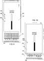
- FIG. 7Another example of control of the electronic device is described herein with reference to FIG 7. and FIG. 8 with continued reference to FIG. 4 .
- a media playeris utilized to play an audio file.
- the position of playback of the audio fileis illustrated in the slide control 702.
- the electronic device 100In response to detecting a touch on the touch-sensitive display 118, at a location associated with the slider control bar 702 at 402, the electronic device 100 enters a playback position control mode and the initial playback position of the media file is adjusted at 404.
- the initial playback positionis adjusted based on the starting position of the touch-sensitive display 118 relative to the physical keyboard 120 when initiation of control of the adjustable setting is detected.
- the touch-sensitive display 118is in the first position and thus the keyboard is not exposed for use when initiation of playback position control mode is detected.
- the initial playback position of the audio fileis adjusted to the end of the slider control bar 702, as illustrated in FIG. 7 .
- the touch-sensitive display 118As the touch-sensitive display 118 is moved relative to the physical keyboard 120, toward the second position, the movement is detected at 406 and the playback position of the audio file is adjusted at 408.
- the touch-sensitive display 118is moved relative to the physical keyboard 120, to about half way between the first position and the second position, as shown in FIG. 8 and thus, the playback position is adjusted to about half way along the slider control bar 702.
- a touch on the physical keyboard 120is detected at 410 and, in response, the control mode is exited at 412 and control of the playback position with movement of the touch-sensitive display 118 relative to the physical keyboard 120 is discontinued at 412.
- a touch on the physical keyboardis utilized to discontinue adjustment of the playback position.
- the touch-sensitive display 118may be moved relative to the physical keyboard 120 without further adjustment of the playback position to facilitate movement of the touch-sensitive display 118 into a desired position without adjusting the playback position further.
- the setting, or position, of the playback of the audio fileis moved generally in the same direction as the movement of the touch-sensitive display 118 relative to the physical keyboard 120.
- the settingis adjusted side to side in the orientation illustrated in FIG. 7 and FIG. 8 , along with movement of the touch-sensitive display 118.
- FIG. 9 and FIG. 10Yet another example of control of the electronic device is described with reference to FIG. 9 and FIG. 10 .
- a volume control buttonis displayed on the touch-sensitive display 118.
- the electronic device 100In response to detecting a touch on the touch-sensitive display 118, at a location associated with the volume control button at 402, the electronic device 100 enters a volume control mode. In this example, however, the initial position of the volume is not adjusted based on the starting position of the touch-sensitive display 118 relative to the physical keyboard 120.
- a first indicator 902 and a second indicator 904are displayed on the touch-sensitive display 118.
- the first indicator 902illustrates the initial position of the volume within the volume range.
- the second indicator 906illustrates the position of the touch-sensitive display 118 relative to the physical keyboard 120.
- an arrow 906is shown to illustrate a direction of movement of the touch-sensitive display 118 to begin controlling the volume setting within the volume range.
- Other informationmay also be displayed to instruct or guide the user.
- the touch-sensitive display 118is then moved relative to the physical keyboard 120 and the second indicator 904 is moved along with movement of the touch-sensitive display 118, until the second indicator 904 is aligned with the first indicator 902.
- control of the position of the volume settingbegins.
- further movement of the touch-sensitive display 118 relative to the keyboard 120results in adjustment of the position of the volume setting within the range.
- the touch-sensitive display 118is moved relative to the physical keyboard 120, the movement is detected at 406 and the volume is adjusted at 408.
- the remaining processes in the methodare similar to those described above with reference to FIG. 4 .
- a position of an adjustable settingmay be controlled by movement of the display relative to the keyboard.
- the use of physical keys to control such adjustable settingsis unnecessary.
Landscapes
- Engineering & Computer Science (AREA)
- Theoretical Computer Science (AREA)
- General Engineering & Computer Science (AREA)
- Physics & Mathematics (AREA)
- General Physics & Mathematics (AREA)
- Human Computer Interaction (AREA)
- Computer Hardware Design (AREA)
- Signal Processing (AREA)
- Mathematical Physics (AREA)
- Multimedia (AREA)
- Health & Medical Sciences (AREA)
- Audiology, Speech & Language Pathology (AREA)
- General Health & Medical Sciences (AREA)
- User Interface Of Digital Computer (AREA)
Description
- The present disclosure relates to an electronic device including a display and a keyboard that is moveable relative to the display and to the control of such an electronic device.
- Electronic devices, including portable electronic devices, have gained widespread use and may provide a variety of functions including, for example, telephonic, electronic messaging and other personal information manager (PIM) application functions. Portable electronic devices include several types of devices including mobile stations such as simple cellular telephones, smart telephones (smart phones), Personal Digital Assistants (PDAs), and tablet computers with wireless network communications or near-field communications connectivity such as Bluetooth® capabilities.
- Portable electronic devices such as PDAs, or tablet computers are generally intended for handheld use and ease of portability. Displays that are moveable relative to a keyboard, from a position in which the keyboard is hidden to a position in which the keyboard is exposed for use are particularly useful on portable electronic devices, which are small and may have limited space for user input and output.
- Improvements in electronic devices with touch-sensitive input devices are desirable.
US 2011/0053650 A1 discloses a mobile terminal and display controlling method that includes detecting whether the position of the keypad is shifted to cover a partial display region of the display unit, if it is detected that the position of the keypad is shifted, changing a normal display mode into a control display mode, and if the control display mode is entered, performing a display operation corresponding to the control display mode in a different display region except the partial display region. Accordingly, in case that a keypad is located to cover a display region of a display unit in part, the present invention enables a display function to be effectively performed in the rest of the display region except the partially covered display region.- The invention is defined by the appended independent claims 1, 10 and 11 and advantageous embodiments of the invention are indicated in the dependent claims.
- Embodiments of the present disclosure will now be described, by way of example only, with reference to the attached figures, in which:
FIG. 1 is a block diagram of an example of a portable electronic device in accordance with the disclosure;FIG. 2 is a front view of an example of a portable electronic device including a keyboard and a display that is movable relative to the keyboard, with the display in a first position, in accordance with the present disclosure;FIG. 3 is a front view of an example of the portable electronic device ofFIG. 2 with the display in a second position, in accordance with the present disclosure;FIG. 4 is a flowchart illustrating an example of a method of controlling an electronic device in accordance with the disclosure;FIG. 5 and FIG. 6 illustrate an example of control of the electronic device ofFIG. 2 and 3 in accordance with the present disclosure;FIG. 7 and FIG. 8 illustrate another example of control of the electronic device ofFIG. 2 and 3 in accordance with the present disclosure; andFIG. 9 and FIG. 10 illustrate yet another example of control of the electronic device ofFIG. 2 and 3 in accordance with the present disclosure.- The following describes an electronic device including a keyboard and a display moveable relative to the keyboard, between a first position in which the keyboard is exposed for use and a second position in which the keyboard is not exposed, and a method of controlling the electronic device. The method includes, in response to detecting initiation of control of a position of an adjustable setting within a range, entering a control mode at the electronic device, and, in response to detecting movement of the display relative to the keyboard of the electronic device, adjusting the position of the adjustable setting within the range.
- For simplicity and clarity of illustration, reference numerals may be repeated among the figures to indicate corresponding or analogous elements. Numerous details are set forth to provide an understanding of the examples described herein. The examples may be practiced without these details. In other instances, well-known methods, procedures, and components are not described in detail to avoid obscuring the examples described. The description is not to be considered as limited to the scope of the examples described herein.
- The disclosure generally relates to an electronic device, such as a portable electronic device. Examples of portable electronic devices include mobile, or handheld, wireless communication devices such as pagers, cellular phones, cellular smart-phones, wireless organizers, personal digital assistants, wirelessly enabled notebook computers, tablet computers, mobile internet devices, electronic navigation devices, and so forth.
- A block diagram of an example of an
electronic device 100 is shown inFIG. 1 . Theelectronic device 100 includes multiple components, such as aprocessor 102 that controls the overall operation of theelectronic device 100. Communication functions, including data and voice communications, are performed through acommunication subsystem 104. Data received by theelectronic device 100 is decompressed and decrypted by adecoder 106. Thecommunication subsystem 104 receives messages from and sends messages to awireless network 150. Thewireless network 150 may be any type of wireless network, including, but not limited to, data wireless networks, voice wireless networks, and networks that support both voice and data communications. Apower source 142, such as one or more rechargeable batteries or a port to an external power supply, powers theelectronic device 100. - The
processor 102 interacts with other components, such as a Random Access Memory (RAM) 108,memory 110, a touch-sensitive display 118, aphysical keyboard 120, an auxiliary input/output (I/O)subsystem 124, adata port 126, aspeaker 128, amicrophone 130, short-range communications 132 andother device subsystems 134. The touch-sensitive display 118 includes adisplay 112 andtouch sensors 114 that are coupled to at least onecontroller 116 that is utilized to interact with theprocessor 102. Input via a graphical user interface is provided via the touch-sensitive display 118. Thus, thetouch sensors 114 and thecontroller 116 are utilized as an input device. Information, such as text, characters, symbols, images, icons, and other items that may be displayed or rendered on a portable electronic device, is displayed on the touch-sensitive display 118 via theprocessor 102. The keyboard may be, for example, aphysical keyboard 120 that includes a plurality of mechanical keys that have mechanical switches or contacts for input to theelectronic device 100 when a mechanical key of the keyboard is depressed by a sufficient force to oppose a bias of the mechanical key. In this example,touch sensors 122 are disposed on thephysical keyboard 120 and thetouch sensors 122 are coupled to acontroller 123. Thus, in addition to depression of the mechanical keys of thephysical keyboard 120 for input to the portableelectronic device 100, touches on the mechanical keys are also detected for input to theprocessor 102. - The touch-
sensitive display 118 is moveable relative to thephysical keyboard 120. Akeyboard sensor 138 is utilized to detect a location of the touch-sensitive display 118 relative to thephysical keyboard 120 of theelectronic device 100. - The
processor 102 may also interact with anaccelerometer 136 that may be utilized to detect direction of gravitational forces or gravity-induced reaction forces. - To identify a subscriber for network access, the
electronic device 100 may utilize a Subscriber Identity Module or a Removable User Identity Module (SIM/RUIM)card 144 for communication with a network, such as thewireless network 150. Alternatively, user identification information may be programmed intomemory 110. - The
electronic device 100 includes anoperating system 146 and software programs, applications, orcomponents 148 that are executed by theprocessor 102 and are typically stored in a persistent, updatable store such as thememory 110. Additional applications or programs may be loaded onto theelectronic device 100 through thewireless network 150, the auxiliary I/O subsystem 124, thedata port 126, the short-range communications subsystem 132, or any othersuitable subsystem 134. - A received signal such as a text message, an e-mail message, or web page download is processed by the
communication subsystem 104 and input to theprocessor 102. Theprocessor 102 processes the received signal for output to thedisplay 112 and/or to the auxiliary I/O subsystem 124. A subscriber may generate data items, for example e-mail messages, which may be transmitted over thewireless network 150 through thecommunication subsystem 104. For voice communications, the overall operation of theelectronic device 100 is similar. Thespeaker 128 outputs audible information converted from electrical signals, and themicrophone 130 converts audible information into electrical signals for processing. - The touch-
sensitive display 118 may be any suitable touch-sensitive display, such as a capacitive touch-sensitive display. A capacitive touch-sensitive display includescapacitive touch sensors 114. The capacitive touch sensors may comprise any suitable material, such as indium tin oxide (ITO). - One or more touches, also known as touch contacts or touch events, may be detected by the touch-
sensitive display 118. Theprocessor 102 may determine attributes of the touch, including a location of the touch. Touch location data may include data for an area of contact or data for a single point of contact, such as a point at or near a center of the area of contact. The location of a detected touch may include x and y components, e.g., horizontal and vertical components, respectively, with respect to one's view of the touch-sensitive display 118. A touch may be detected from any suitable input member, such as a finger, thumb, appendage, or other objects, for example, a stylus, pen, or other pointer, depending on the nature of the touch-sensitive display 118. Multiple simultaneous touches may be detected. A tap, which is a particular type of touch may be a touch that ends within a threshold period of time. Thus, the touch contact with the touch-sensitive display 118 is relatively short because contact ends within a threshold period of time of beginning. - One or more gestures may also be detected by the touch-
sensitive display 118. A gesture, such as a swipe, also known as a flick, is a particular type of touch on a touch-sensitive display 118 and may begin at an origin point and continue to an end point, for example, a concluding end of the gesture. A gesture may be identified by attributes of the gesture, including the origin point, the end point, the distance travelled, the duration, the velocity, and the direction, for example. A gesture may be long or short in distance and/or duration. Two points of the gesture may be utilized to determine a direction of the gesture. A gesture may also include a hover. A hover may be a touch at a location that is generally unchanged over a period of time or is associated with the same selection item for a period of time. - The
touch sensors 122 on thephysical keyboard 120 may be any suitable touch sensors, such as capacitive touch-sensors and may comprise any suitable material, such as indium tin oxide (ITO). Optionally, thetouch sensors 122 disposed on thephysical keyboard 120 may be coupled to thesame controller 116 as the touch sensors of touch-sensitive display 118 such that a single controller is utilized rather than twocontrollers - One or more touches on the keys of the
keyboard 120 may be detected. Theprocessor 102 may determine attributes of the touch, including a location of the touch. Touch location data may include data for an area of contact or data for a single point of contact, such as a point at or near a center of the area of contact. The location of a detected touch may include x and y components, e.g., horizontal and vertical components, respectively, with respect to one's view of thekeyboard 120. A touch may be detected from any suitable input member and multiple simultaneous touches may be detected. - One or more gestures may also be detected by the
touch sensors 122 disposed on thekeyboard 120. A gesture on the keys of thekeyboard 120 may be identified by attributes of the gesture, including the origin point, the end point, the distance travelled, the duration, the velocity, and the direction, for example. A gesture may be long or short in distance and/or duration. Two points of the gesture may be utilized to determine a direction of the gesture. A gesture may also include a hover. - The touch-
sensitive display 118 includes a display area in which information may be displayed, and a non-display area extending around the periphery of the display area. Information is not displayed in the non-display area by the display, which non-display area is utilized to accommodate, for example, electronic traces or electrical connections, adhesives or other sealants, and/or protective coatings around the edges of the display area. The non-display area may be referred to as an inactive area and is not part of the physical housing or frame of the electronic device. Typically, no pixels of the display are in the non-display area, thus no image is displayed by thedisplay 112 in the non-display area. Touch sensors may be disposed in the non-display area, which touch sensors may be extended from the touch sensors in the display area or distinct or separate touch sensors from the touch sensors in the display area. A touch on the touch-sensitive display 118, including a gesture, may be associated with the display area, the non-display area, or both areas. The touch sensors may extend across substantially the entire non-display area or may be disposed in only part of the non-display area. - A front view of an example of the
electronic device 100 is shown inFIG. 2 . Theelectronic device 100 includes adisplay housing 202 in which the touch-sensitive display 118 is disposed. Thedisplay housing 202 is utilized to house or support components including at least some of the components shown inFIG. 1 . - The
physical keyboard 120 is disposed in akeyboard housing 204, which is shown inFIG. 3 , below the touch-sensitive display 118 in the orientation illustrated inFIG. 3 . Thephysical keyboard 120 includes a plurality ofmechanical keys 206. Each one of themechanical keys 206 of the keyboard is associated with characters or a function such that the characters are entered utilizing themechanical keys 206. Thekeyboard housing 204 may also be utilized to house or support components including at least some of the components shown inFIG. 1 . - To move the touch-
sensitive display 118 relative to thephysical keyboard 120,display housing 202 is moveable relative to thekeyboard housing 204 by sliding thedisplay housing 202 between a first position in which thekeyboard housing 204 is stacked with thedisplay housing 202 such that thephysical keyboard 120 is disposed between thedisplay housing 202 and a back of thekeyboard housing 204, as shown inFIG. 2 , and a second position in which thekeyboard housing 204 extends from thedisplay housing 202 to expose thephysical keyboard 120 below the touch-sensitive display 118 in the orientation in which the portableelectronic device 100 is illustrated inFIG. 3 . - Thus, touch-
sensitive display 118 is moveable relative to thephysical keyboard 120, between the first position, shown inFIG. 2 , in which the physical keyboard is not exposed and the second position, shown inFIG. 3 , in which thephysical keyboard 120 is exposed for use. Thephysical keyboard 120 is therefore selectively exposable for use. Thekeyboard sensor 138, referred to above with reference toFIG. 1 , is arranged and constructed to detect a position of thedisplay housing 202 relative to thekeyboard housing 204. Thekeyboard sensor 138 is coupled to theprocessor 102 to detect that the touch-sensitive display 118 is in the first position, the second position, or in a location between the first and the second positions. Theprocessor 102 in connection with thekeyboard sensor 138 may detect the percentage that thephysical keyboard 120 is exposed. Thus, thekeyboard sensor 138 together with theprocessor 102 detects movement of the touch-sensitive display 118 relative to thephysical keyboard 120. - The
physical keyboard 120 may be a QWERTY keyboard. Alternatively, other keyboard layouts may be successfully implemented, such as an AZERTY keyboard, a QWERTZ keyboard, or any other suitable keyboard. - Information may be displayed on the touch-
sensitive display 118. The information displayed may include any suitable information such as icons, text, pictures, video, documents, a webpage, or any other suitable information. The information may be associated with, for example, a home page, a menu or submenu, an application or applications, and so forth. The information may be selectable, for example, by a touch on the touch-sensitive display 118, or by a touch, such as a hover gesture, a tap, a double tap, or other suitable touch, on thephysical keyboard 120. - A virtual keyboard may also be displayed. The keys of the virtual keyboard may be selectable by a touch on an area of the touch-
sensitive display 118 associated with the respective key. Display of the virtual keyboard may be discontinued in response to movement of thedisplay housing 202 relative to thekeyboard housing 204 to the second position, as shown inFIG.3 , to thereby expose thephysical keyboard 120. - A flowchart illustrating a method of controlling an electronic device that has a display moveable relative to the keyboard, such as the
electronic device 100, is shown inFIG. 4 . The method may be carried out by software executed, for example, by aprocessor 102 in a portableelectronic device 100. Coding of software for carrying out such a method is within the scope of a person of ordinary skill in the art given the present description. The method may contain additional or fewer processes than shown and/or described, and may be performed in a different order. Computer-readable code executable by at least one processor of the portable electronic device to perform the method may be stored in a computer-readable medium, such as a non-transitory computer-readable device. - The method illustrated in
FIG. 4 may be carried out, for example, any time the portableelectronic device 120 is on and is running the operating system or an application. - In response to detecting initiation of control of an adjustable setting within a range at 402, the method continues at 404. Initiation of control of the adjustable setting may be detected by detecting a touch at a location on the touch-
sensitive display 118, for example. The location may include information displayed such as a graphical representation, a word or symbol, or any suitable identifier or information. For example, the location may include a graphical representation of a button, thus providing a selectable button on the touch-sensitive display 118. - The adjustable setting may be, for example, a volume output such as volume of a notification, a brightness of the touch-
sensitive display 118, or any other suitable setting. Alternatively, the adjustable setting may be a playback position within a file in a media player. For example, the adjustable setting may be a position within a song or a position within a video. The adjustable setting may be application dependent such that the adjustable setting may be identified based on the application running on the portable electronic device at the time the initiation of control is detected. The adjustable setting may be identified from more than one adjustable setting in the group of adjustable settings. The adjustable setting may be identified based on the location of the touch on the touch-sensitive display 118, for example. Thus, a volume control may be identified in response to detecting a touch at a first location associated with the volume and a video playback position may be identified in response to detecting a touch at a second location associated with the video. - The control mode is entered at 404 and an initial position of the adjustable setting may optionally be adjusted based on the starting position of the touch-
sensitive display 118 relative to thephysical keyboard 120 when initiation of control of the adjustable setting is detected. Thus, for example, a volume, brightness, or playback position may be initially adjusted based on the position of the touch-sensitive display 118 relative to thephysical keyboard 120 at the time that initiation of control of the adjustable setting is detected. - In response to detecting movement of the touch-
sensitive display 118 relative to thephysical keyboard 120 at 406, the process continues at 408. The movement of the touch-sensitive display 118 relative to thephysical keyboard 120 may be movement toward the first position in which the keyboard is not exposed or movement toward the second position in which the keyboard is exposed for use. Thus, thekeyboard sensor 138 is utilized to detect any movement of the touch-sensitive display 118 relative to thephysical keyboard 120 after initiation of control of the adjustable setting. The percentage or extent that thephysical keyboard 120 is exposed is detected and changes in the percentage or extent that thephysical keyboard 120 is exposed by movement of the touch-sensitive display 118 are detected. - A position of an adjustable setting within the range is adjusted based on the percentage or extent that the physical keyboard is exposed at 408. Thus, the position of the adjustable setting within the range is dependent on the location of the touch-
sensitive display 118 relative to thephysical keyboard 120 of theelectronic device 100. For example, a volume or a brightness level may be adjusted by a percentage increase that is generally equivalent to the percentage or extent that the touch-sensitive display 118 is moved within the range of movement of the touch-sensitive display 118 relative to thephysical keyboard 120. Alternatively, a playback position of a video or audio file may be changed by a percentage that is generally equivalent to the percentage or extent that the touch-sensitive display 118 is moved relative to thephysical keyboard 120. Thus, the position of the adjustable setting may be adjusted in either direction along with movement of the touch-sensitive display 118 relative to thephysical keyboard 120. - In response to detecting an end of control of the position of the adjustable setting at 410, the control mode is exited and adjustment of the position of the adjustable setting within the range in response to detecting movement of the touch-
sensitive display 118 relative to thephysical keyboard 120 is discontinued at 412. The end of control of the position of the adjustable setting may be detected, for example, when a touch, which may be a gesture or a touch on a key, is detected on thephysical keyboard 120, or when a second touch is detected on the touch-sensitive display 118. Alternatively, the end of control of the position of the adjustable setting may be detected by detecting a pause in the movement of the touch-sensitive display 118 relative to thephysical keyboard 120 such that the relative movement of the touch-sensitive display 118 is stopped for a period of time that meets or exceeds a threshold period of time. Alternatively, the end of control of the position of the adjustable setting may be detected when theelectronic device 100 detects that a touch on the touch-sensitive display 118 is ended. Thus, a touch on the touch-sensitive display 118 may be utilized to enter the control mode and theelectronic device 100 remains in the control mode until the same touch on the touch-sensitive display 118 is ended. - Further movement of the touch-
sensitive display 118 relative to thephysical keyboard 120 does not control the position of the adjustable setting after detecting the end of control of the position of the adjustable setting. - Rather than setting the position of the adjustable setting based on the position of the touch-
sensitive display 118 when initiation of control of the adjustable setting is detected at 404, control of the position of the adjustable setting may begin when the touch-sensitive display 118 is moved to a position relative to thephysical keyboard 120 that generally matches the initial position of the adjustable setting at the time initiation of control is detected. For example, the touch-sensitive display 118 may be utilized to display a first marker or indicator illustrating the initial position of the adjustable setting within the range and a second marker or indicator may be displayed to illustrate the position of the touch-sensitive display 118 relative to thephysical keyboard 120. The touch-sensitive display 118 is then moved relative to thephysical keyboard 120 and the second marker or indicator is moved along with movement of the touch-sensitive display 118, until the second marker or indicator is aligned with the first marker or indicator. When alignment is detected, control of the position of the adjustable setting begins. Thus, further movement of the touch-sensitive display 118 relative to thekeyboard 120, after alignment of the first marker with the second marker, results in adjustment of the position of the adjustable setting. - Reference is made to
FIG. 5 and FIG. 6 with continued reference toFIG. 4 to describe an example of control of theelectronic device 100. In the present example, avolume control button 502 is displayed on the touch-sensitive display 118. The volume control button may be displayed, for example, in response to launching or executing an application, or may be displayed as part of a home screen. Alternatively, the volume control button may be a physical button in thedisplay housing 202. - In response to detecting a touch illustrated by the
circle 504 on the touch-sensitive display 118, at a location associated with thevolume control button 502 at 402, theelectronic device 100 enters a volume control mode and the initial position of the volume is adjusted at 404. The initial position of the volume is adjusted based on the starting position of the touch-sensitive display 118 relative to thephysical keyboard 120 when initiation of control of the adjustable setting is detected. In the present example, the touch-sensitive display 118 is in the second position such that thephysical keyboard 120 is entirely exposed for use when initiation of the volume control mode is detected and the initial position of the volume is adjusted to a maximum or 100% volume. - As the touch-
sensitive display 118 is moved relative to thephysical keyboard 120, toward the first position, the movement is detected at 406 and the volume is adjusted at 408. For the purpose of the present example, the touch-sensitive display 118 is moved relative to thephysical keyboard 120, to about half way between the first position and the second position, as shown inFIG. 6 and thus, the volume is adjusted to a level that is about half way between the lower-most volume level and the upper-most volume level. - The movement of the touch-
sensitive display 118 relative to thephysical keyboard 120 is paused for a period of time that meets a threshold, with the touch-sensitive display 118 about half way between the first position and the second position. The pause in movement is detected at 410 and, in response, the control mode is exited and control of the volume with movement of the touch-sensitive display 118 relative to thephysical keyboard 120 is discontinued at 412. - Thus, after setting the volume to the desired level by movement of the touch-
sensitive display 118 relative to thephysical keyboard 120, the relative movement is discontinued. After exiting the control mode, the touch-sensitive display 118 is moveable relative to thephysical keyboard 120 without further adjustment of the volume to facilitate movement of the touch-sensitive display 118 to the second position for use of thephysical keyboard 120 without adjusting the volume further. - As illustrated in the example of
FIG. 5 and FIG. 6 , the volume setting is moved along thevolume control bar 506, generally in the same direction as the movement of the touch-sensitive display 118 relative to thephysical keyboard 120. Thus, the volume setting is adjusted up and down in the orientation illustrated inFIG. 5 and FIG. 6 , along with movement of the touch-sensitive display 118. - Another example of control of the electronic device is described herein with reference to
FIG 7. and FIG. 8 with continued reference toFIG. 4 . In the present example, a media player is utilized to play an audio file. The position of playback of the audio file is illustrated in theslide control 702. - In response to detecting a touch on the touch-
sensitive display 118, at a location associated with theslider control bar 702 at 402, theelectronic device 100 enters a playback position control mode and the initial playback position of the media file is adjusted at 404. The initial playback position is adjusted based on the starting position of the touch-sensitive display 118 relative to thephysical keyboard 120 when initiation of control of the adjustable setting is detected. In the present example, the touch-sensitive display 118 is in the first position and thus the keyboard is not exposed for use when initiation of playback position control mode is detected. In this example, the initial playback position of the audio file is adjusted to the end of theslider control bar 702, as illustrated inFIG. 7 . - As the touch-
sensitive display 118 is moved relative to thephysical keyboard 120, toward the second position, the movement is detected at 406 and the playback position of the audio file is adjusted at 408. For the purpose of the present example, the touch-sensitive display 118 is moved relative to thephysical keyboard 120, to about half way between the first position and the second position, as shown inFIG. 8 and thus, the playback position is adjusted to about half way along theslider control bar 702. - For the purpose of the present example, a touch on the
physical keyboard 120 is detected at 410 and, in response, the control mode is exited at 412 and control of the playback position with movement of the touch-sensitive display 118 relative to thephysical keyboard 120 is discontinued at 412. - Thus, after setting the playback position to the desired location by movement of the touch-
sensitive display 118 relative to thephysical keyboard 120, a touch on the physical keyboard is utilized to discontinue adjustment of the playback position. After exiting the control mode, the touch-sensitive display 118 may be moved relative to thephysical keyboard 120 without further adjustment of the playback position to facilitate movement of the touch-sensitive display 118 into a desired position without adjusting the playback position further. - In the example of
FIG. 7 and FIG. 8 , the setting, or position, of the playback of the audio file is moved generally in the same direction as the movement of the touch-sensitive display 118 relative to thephysical keyboard 120. Thus, the setting is adjusted side to side in the orientation illustrated inFIG. 7 and FIG. 8 , along with movement of the touch-sensitive display 118. - Yet another example of control of the electronic device is described with reference to
FIG. 9 and FIG. 10 . As in the example described above with reference toFIG. 5 and FIG. 6 , a volume control button is displayed on the touch-sensitive display 118. - In response to detecting a touch on the touch-
sensitive display 118, at a location associated with the volume control button at 402, theelectronic device 100 enters a volume control mode. In this example, however, the initial position of the volume is not adjusted based on the starting position of the touch-sensitive display 118 relative to thephysical keyboard 120. - Instead, a
first indicator 902 and asecond indicator 904 are displayed on the touch-sensitive display 118. Thefirst indicator 902 illustrates the initial position of the volume within the volume range. Thesecond indicator 906 illustrates the position of the touch-sensitive display 118 relative to thephysical keyboard 120. In the present example, anarrow 906 is shown to illustrate a direction of movement of the touch-sensitive display 118 to begin controlling the volume setting within the volume range. Other information may also be displayed to instruct or guide the user. - The touch-
sensitive display 118 is then moved relative to thephysical keyboard 120 and thesecond indicator 904 is moved along with movement of the touch-sensitive display 118, until thesecond indicator 904 is aligned with thefirst indicator 902. In response to detecting alignment ofsecond indicator 904 with thefirst indicator 902, control of the position of the volume setting begins. Thus, further movement of the touch-sensitive display 118 relative to thekeyboard 120, results in adjustment of the position of the volume setting within the range. - Thus, as the touch-
sensitive display 118 is moved relative to thephysical keyboard 120, the movement is detected at 406 and the volume is adjusted at 408. The remaining processes in the method are similar to those described above with reference toFIG. 4 . - Advantageously, a position of an adjustable setting may be controlled by movement of the display relative to the keyboard. Thus, the use of physical keys to control such adjustable settings is unnecessary.
Claims (11)
- A method of controlling an electronic device (100) having a display (112) moveable relative to a keyboard (120), between a first position in which the keyboard (120) is exposed for use and a second position in which the keyboard (120) is not exposed, the method comprising:in response to detecting (402) initiation of control of a position of an adjustable setting within a range and wherein the detecting (402) comprises detecting a touch at a location on the display (112), entering (404) a control mode at the electronic device (100);in response to detecting (406) movement of the display (112) relative to the keyboard (120) of the electronic device (100), adjusting (408) the position of the adjustable setting within the range,
the methodcharacterized in that:
the position of the adjustable setting within the range is dependent on the location of the display (112) relative to the keyboard of the electronic device. - The method according to claim 1, wherein the position of the adjustable setting within the range comprises a volume setting within a volume range of the electronic device (100).
- The method according to claim 1 or 2, wherein the position of the adjustable setting within the range comprises a playback position within a file in a media player.
- The method according to any preceding claim, comprising, in response to detecting (410) an end of control of the position of the adjustable setting within a range, exiting the control mode such that adjustment of the position of the adjustable setting within the range in response to detecting movement of the display (112) relative to the keyboard (120) is discontinued (412).
- The method according to claim 4, wherein detecting (410) the end of control of the position of the adjustable setting within the range comprises detecting a touch on the keyboard (120).
- The method according to claim 4, wherein detecting (410) the end of control of the position of the adjustable setting within the range comprises detecting stoppage of the movement of the display relative to the keyboard (120) for a threshold period of time.
- The method according to any preceding claim, comprising, in response to detecting initiation of the control of the position of the adjustable setting, adjusting an initial position of the adjustable setting within the range based on an initial position of the display (112) relative to the keyboard.
- The method according to any preceding claim, wherein the adjustable setting is dependent on an application running on the electronic device when initiation of control is detected.
- The method according to any preceding claim, wherein the setting is adjusted within the range to move the setting in a first direction as the display (112) is moved toward the second position and the setting is adjusted within the range to move the setting in a second direction, opposite the first direction, as the display is moved toward the first position.
- A computer program which when executed by at least one processor (102) of a portable electronic device is configured to perform the method according to any preceding claim.
- An electronic device comprising:a keyboard (120);a display (112) to display information thereon, wherein the display (112) is moveable relative to the keyboard (120), between a first position in which the keyboard (120) is exposed for use and a second position in which the keyboard is not exposed;a sensor (138) for detecting a position of the display (112) relative to the keyboard (120);a processor coupled to the display (112), the keyboard (120), and the sensor (138) andwherein the processor is configured with program instructions to carry out the method of any one of claims 1 to 9.
Applications Claiming Priority (1)
| Application Number | Priority Date | Filing Date | Title |
|---|---|---|---|
| US15/141,473US10359924B2 (en) | 2016-04-28 | 2016-04-28 | Control of an electronic device including display and keyboard moveable relative to the display |
Publications (2)
| Publication Number | Publication Date |
|---|---|
| EP3239804A1 EP3239804A1 (en) | 2017-11-01 |
| EP3239804B1true EP3239804B1 (en) | 2020-10-14 |
Family
ID=58410102
Family Applications (1)
| Application Number | Title | Priority Date | Filing Date |
|---|---|---|---|
| EP17162040.4AActiveEP3239804B1 (en) | 2016-04-28 | 2017-03-21 | Control of an electronic device including display and keyboard moveable relative to the display |
Country Status (2)
| Country | Link |
|---|---|
| US (1) | US10359924B2 (en) |
| EP (1) | EP3239804B1 (en) |
Families Citing this family (19)
| Publication number | Priority date | Publication date | Assignee | Title |
|---|---|---|---|---|
| USD822633S1 (en)* | 2015-11-04 | 2018-07-10 | Lenovo (Beijing) Co., Ltd. | Flexible electronic device |
| USD820801S1 (en)* | 2015-11-04 | 2018-06-19 | Lenovo (Beijing) Co., Ltd. | Flexible electronic device |
| US10534406B2 (en)* | 2018-06-29 | 2020-01-14 | Intel Corporation | Dual screen electronic devices with stowable keyboards |
| US10841174B1 (en)* | 2018-08-06 | 2020-11-17 | Apple Inc. | Electronic device with intuitive control interface |
| US11500655B2 (en) | 2018-08-22 | 2022-11-15 | Microstrategy Incorporated | Inline and contextual delivery of database content |
| US11238210B2 (en) | 2018-08-22 | 2022-02-01 | Microstrategy Incorporated | Generating and presenting customized information cards |
| US11682390B2 (en) | 2019-02-06 | 2023-06-20 | Microstrategy Incorporated | Interactive interface for analytics |
| US11593837B2 (en) | 2019-02-22 | 2023-02-28 | Aerial Technologies Inc. | Advertisement engagement measurement |
| US11913970B2 (en) | 2019-02-22 | 2024-02-27 | Aerial Technologies Inc. | Wireless motion detection using multiband filters |
| WO2020170221A1 (en) | 2019-02-22 | 2020-08-27 | Aerial Technologies Inc. | Handling concept drift in wi-fi-based localization |
| US11218769B2 (en)* | 2019-02-22 | 2022-01-04 | Aerial Technologies Inc. | Smart media display |
| US11082109B2 (en) | 2019-02-22 | 2021-08-03 | Aerial Technologies Inc. | Self-learning based on Wi-Fi-based monitoring and augmentation |
| US11586952B2 (en) | 2019-02-22 | 2023-02-21 | Aerial Technologies Inc. | Robotic H matrix creation |
| US11448726B2 (en) | 2019-08-28 | 2022-09-20 | Aerial Technologies Inc. | System and method for presence and pulse detection from wireless signals |
| US11523253B2 (en) | 2019-09-06 | 2022-12-06 | Aerial Technologies Inc. | Monitoring activity using Wi-Fi motion detection |
| CN110798552A (en)* | 2019-09-19 | 2020-02-14 | 华为技术有限公司 | A kind of volume adjustment method and electronic device |
| US11082487B1 (en) | 2020-09-22 | 2021-08-03 | Vignet Incorporated | Data sharing across decentralized clinical trials using customized data access policies |
| US12007870B1 (en) | 2022-11-03 | 2024-06-11 | Vignet Incorporated | Monitoring and adjusting data collection from remote participants for health research |
| US11790107B1 (en) | 2022-11-03 | 2023-10-17 | Vignet Incorporated | Data sharing platform for researchers conducting clinical trials |
Family Cites Families (22)
| Publication number | Priority date | Publication date | Assignee | Title |
|---|---|---|---|---|
| US7388578B2 (en) | 2004-07-01 | 2008-06-17 | Nokia Corporation | Touch display PDA phone with slide keypad |
| JP4922797B2 (en)* | 2007-03-13 | 2012-04-25 | 任天堂株式会社 | Information processing apparatus and program thereof |
| TWI393029B (en)* | 2007-12-31 | 2013-04-11 | Htc Corp | Electronic device and method for executing commands in the same |
| KR20090103185A (en) | 2008-03-27 | 2009-10-01 | 삼성전자주식회사 | Mobile terminal having a moving keypad |
| KR101020045B1 (en)* | 2008-08-29 | 2011-03-09 | 삼성전자주식회사 | Key area control device and method for keyboard without keycap |
| US8787993B2 (en) | 2008-12-11 | 2014-07-22 | Blackberry Limited | System and method for saving data in response to open and close events in a mobile communication device |
| KR20100083036A (en) | 2009-01-12 | 2010-07-21 | 삼성전자주식회사 | Message service support method and portable device using the same |
| US8406816B2 (en)* | 2009-02-03 | 2013-03-26 | Research In Motion Limited | Method and apparatus for implementing a virtual rotary dial pad on a portable electronic device |
| US20100241983A1 (en)* | 2009-03-17 | 2010-09-23 | Walline Erin K | System And Method For Accelerometer Based Information Handling System Keyboard Selection |
| KR101617262B1 (en) | 2009-08-26 | 2016-05-02 | 엘지전자 주식회사 | Mobile terminal and method for controlling displaying thereof |
| TWI492140B (en)* | 2009-08-28 | 2015-07-11 | Compal Electronics Inc | Method for keyboard input and assistant system thereof |
| US8977987B1 (en)* | 2010-06-14 | 2015-03-10 | Google Inc. | Motion-based interface control on computing device |
| CN101937313B (en)* | 2010-09-13 | 2019-11-12 | 中兴通讯股份有限公司 | A kind of method and device of touch keyboard dynamic generation and input |
| US9122318B2 (en)* | 2010-09-15 | 2015-09-01 | Jeffrey R. Spetalnick | Methods of and systems for reducing keyboard data entry errors |
| US8941601B2 (en)* | 2011-04-21 | 2015-01-27 | Nokia Corporation | Apparatus and associated methods |
| US8699740B2 (en)* | 2011-07-22 | 2014-04-15 | Fortune Grand Technology Inc. | Headphone sound-generating structure and method of assembling same |
| US20130191785A1 (en)* | 2012-01-23 | 2013-07-25 | Microsoft Corporation | Confident item selection using direct manipulation |
| WO2013123571A1 (en)* | 2012-02-24 | 2013-08-29 | Research In Motion Limited | Virtual keyboard with dynamically reconfigurable layout |
| JP6071107B2 (en)* | 2012-06-14 | 2017-02-01 | 裕行 池田 | Mobile device |
| KR20140039871A (en)* | 2012-09-25 | 2014-04-02 | 삼성전기주식회사 | Touch screen device and electronic device using the same |
| US10548510B2 (en)* | 2015-06-30 | 2020-02-04 | Harrison James BROWN | Objective balance error scoring system |
| US20170003837A1 (en)* | 2015-06-30 | 2017-01-05 | Integrated Computer Solutions, Inc. | Systems and Methods for Generating, Presenting, and Adjusting Adjustable Virtual Keyboards |
- 2016
- 2016-04-28USUS15/141,473patent/US10359924B2/enactiveActive
- 2017
- 2017-03-21EPEP17162040.4Apatent/EP3239804B1/enactiveActive
Non-Patent Citations (1)
| Title |
|---|
| None* |
Also Published As
| Publication number | Publication date |
|---|---|
| US10359924B2 (en) | 2019-07-23 |
| US20170315711A1 (en) | 2017-11-02 |
| EP3239804A1 (en) | 2017-11-01 |
Similar Documents
| Publication | Publication Date | Title |
|---|---|---|
| EP3239804B1 (en) | Control of an electronic device including display and keyboard moveable relative to the display | |
| US10203858B2 (en) | Portable electronic device and method of controlling the display of information | |
| US10180780B2 (en) | Portable electronic device including touch-sensitive display and method of controlling selection of information | |
| EP3037948B1 (en) | Portable electronic device and method of controlling display of selectable elements | |
| EP3051407A1 (en) | Electronic device and method of controlling display of information | |
| US9465446B2 (en) | Electronic device including mechanical keyboard having touch sensors for detecting touches and actuation of mechanical keys | |
| EP3211510B1 (en) | Portable electronic device and method of providing haptic feedback | |
| US8887086B2 (en) | Portable electronic device and method of controlling same | |
| EP3352068B1 (en) | Portable electronic device including physical keyboard and method of controlling selection of information | |
| EP3079053B1 (en) | Portable electronic device including touch-sensitive display and method of controlling selection of information | |
| US20120007876A1 (en) | Electronic device and method of tracking displayed information | |
| EP3457269B1 (en) | Electronic device and method for one-handed operation | |
| EP3153960B1 (en) | Electronic device and method of controlling same | |
| EP2405333A1 (en) | Electronic device and method of tracking displayed information | |
| EP3287885B1 (en) | Control of an electronic device including display and keyboard moveable relative to the display | |
| EP3477458B1 (en) | Electronic device and method of providing selectable keys of a keyboard | |
| EP2778857A1 (en) | Electronic device including touch-sensitive keyboard and method of controlling same | |
| CA2845397C (en) | Electronic device including touch-sensitive keyboard and method of controlling same | |
| CA2735040C (en) | Portable electronic device and method of controlling same | |
| HK40007643A (en) | Electronic device and method of providing selectable keys of a keyboard |
Legal Events
| Date | Code | Title | Description |
|---|---|---|---|
| PUAI | Public reference made under article 153(3) epc to a published international application that has entered the european phase | Free format text:ORIGINAL CODE: 0009012 | |
| STAA | Information on the status of an ep patent application or granted ep patent | Free format text:STATUS: THE APPLICATION HAS BEEN PUBLISHED | |
| AK | Designated contracting states | Kind code of ref document:A1 Designated state(s):AL AT BE BG CH CY CZ DE DK EE ES FI FR GB GR HR HU IE IS IT LI LT LU LV MC MK MT NL NO PL PT RO RS SE SI SK SM TR | |
| AX | Request for extension of the european patent | Extension state:BA ME | |
| STAA | Information on the status of an ep patent application or granted ep patent | Free format text:STATUS: REQUEST FOR EXAMINATION WAS MADE | |
| 17P | Request for examination filed | Effective date:20180427 | |
| RBV | Designated contracting states (corrected) | Designated state(s):AL AT BE BG CH CY CZ DE DK EE ES FI FR GB GR HR HU IE IS IT LI LT LU LV MC MK MT NL NO PL PT RO RS SE SI SK SM TR | |
| STAA | Information on the status of an ep patent application or granted ep patent | Free format text:STATUS: EXAMINATION IS IN PROGRESS | |
| 17Q | First examination report despatched | Effective date:20181122 | |
| GRAP | Despatch of communication of intention to grant a patent | Free format text:ORIGINAL CODE: EPIDOSNIGR1 | |
| STAA | Information on the status of an ep patent application or granted ep patent | Free format text:STATUS: GRANT OF PATENT IS INTENDED | |
| INTG | Intention to grant announced | Effective date:20200525 | |
| GRAS | Grant fee paid | Free format text:ORIGINAL CODE: EPIDOSNIGR3 | |
| GRAA | (expected) grant | Free format text:ORIGINAL CODE: 0009210 | |
| STAA | Information on the status of an ep patent application or granted ep patent | Free format text:STATUS: THE PATENT HAS BEEN GRANTED | |
| AK | Designated contracting states | Kind code of ref document:B1 Designated state(s):AL AT BE BG CH CY CZ DE DK EE ES FI FR GB GR HR HU IE IS IT LI LT LU LV MC MK MT NL NO PL PT RO RS SE SI SK SM TR | |
| REG | Reference to a national code | Ref country code:GB Ref legal event code:FG4D | |
| REG | Reference to a national code | Ref country code:AT Ref legal event code:REF Ref document number:1324205 Country of ref document:AT Kind code of ref document:T Effective date:20201015 Ref country code:CH Ref legal event code:EP | |
| REG | Reference to a national code | Ref country code:DE Ref legal event code:R096 Ref document number:602017025278 Country of ref document:DE | |
| REG | Reference to a national code | Ref country code:IE Ref legal event code:FG4D | |
| REG | Reference to a national code | Ref country code:AT Ref legal event code:MK05 Ref document number:1324205 Country of ref document:AT Kind code of ref document:T Effective date:20201014 | |
| REG | Reference to a national code | Ref country code:NL Ref legal event code:MP Effective date:20201014 | |
| PG25 | Lapsed in a contracting state [announced via postgrant information from national office to epo] | Ref country code:PT Free format text:LAPSE BECAUSE OF FAILURE TO SUBMIT A TRANSLATION OF THE DESCRIPTION OR TO PAY THE FEE WITHIN THE PRESCRIBED TIME-LIMIT Effective date:20210215 Ref country code:RS Free format text:LAPSE BECAUSE OF FAILURE TO SUBMIT A TRANSLATION OF THE DESCRIPTION OR TO PAY THE FEE WITHIN THE PRESCRIBED TIME-LIMIT Effective date:20201014 Ref country code:NO Free format text:LAPSE BECAUSE OF FAILURE TO SUBMIT A TRANSLATION OF THE DESCRIPTION OR TO PAY THE FEE WITHIN THE PRESCRIBED TIME-LIMIT Effective date:20210114 Ref country code:NL Free format text:LAPSE BECAUSE OF FAILURE TO SUBMIT A TRANSLATION OF THE DESCRIPTION OR TO PAY THE FEE WITHIN THE PRESCRIBED TIME-LIMIT Effective date:20201014 Ref country code:FI Free format text:LAPSE BECAUSE OF FAILURE TO SUBMIT A TRANSLATION OF THE DESCRIPTION OR TO PAY THE FEE WITHIN THE PRESCRIBED TIME-LIMIT Effective date:20201014 Ref country code:GR Free format text:LAPSE BECAUSE OF FAILURE TO SUBMIT A TRANSLATION OF THE DESCRIPTION OR TO PAY THE FEE WITHIN THE PRESCRIBED TIME-LIMIT Effective date:20210115 | |
| REG | Reference to a national code | Ref country code:LT Ref legal event code:MG4D | |
| PG25 | Lapsed in a contracting state [announced via postgrant information from national office to epo] | Ref country code:ES Free format text:LAPSE BECAUSE OF FAILURE TO SUBMIT A TRANSLATION OF THE DESCRIPTION OR TO PAY THE FEE WITHIN THE PRESCRIBED TIME-LIMIT Effective date:20201014 Ref country code:AT Free format text:LAPSE BECAUSE OF FAILURE TO SUBMIT A TRANSLATION OF THE DESCRIPTION OR TO PAY THE FEE WITHIN THE PRESCRIBED TIME-LIMIT Effective date:20201014 Ref country code:BG Free format text:LAPSE BECAUSE OF FAILURE TO SUBMIT A TRANSLATION OF THE DESCRIPTION OR TO PAY THE FEE WITHIN THE PRESCRIBED TIME-LIMIT Effective date:20210114 Ref country code:LV Free format text:LAPSE BECAUSE OF FAILURE TO SUBMIT A TRANSLATION OF THE DESCRIPTION OR TO PAY THE FEE WITHIN THE PRESCRIBED TIME-LIMIT Effective date:20201014 Ref country code:PL Free format text:LAPSE BECAUSE OF FAILURE TO SUBMIT A TRANSLATION OF THE DESCRIPTION OR TO PAY THE FEE WITHIN THE PRESCRIBED TIME-LIMIT Effective date:20201014 Ref country code:IS Free format text:LAPSE BECAUSE OF FAILURE TO SUBMIT A TRANSLATION OF THE DESCRIPTION OR TO PAY THE FEE WITHIN THE PRESCRIBED TIME-LIMIT Effective date:20210214 Ref country code:SE Free format text:LAPSE BECAUSE OF FAILURE TO SUBMIT A TRANSLATION OF THE DESCRIPTION OR TO PAY THE FEE WITHIN THE PRESCRIBED TIME-LIMIT Effective date:20201014 | |
| PG25 | Lapsed in a contracting state [announced via postgrant information from national office to epo] | Ref country code:HR Free format text:LAPSE BECAUSE OF FAILURE TO SUBMIT A TRANSLATION OF THE DESCRIPTION OR TO PAY THE FEE WITHIN THE PRESCRIBED TIME-LIMIT Effective date:20201014 | |
| REG | Reference to a national code | Ref country code:DE Ref legal event code:R097 Ref document number:602017025278 Country of ref document:DE | |
| PG25 | Lapsed in a contracting state [announced via postgrant information from national office to epo] | Ref country code:RO Free format text:LAPSE BECAUSE OF FAILURE TO SUBMIT A TRANSLATION OF THE DESCRIPTION OR TO PAY THE FEE WITHIN THE PRESCRIBED TIME-LIMIT Effective date:20201014 Ref country code:SK Free format text:LAPSE BECAUSE OF FAILURE TO SUBMIT A TRANSLATION OF THE DESCRIPTION OR TO PAY THE FEE WITHIN THE PRESCRIBED TIME-LIMIT Effective date:20201014 Ref country code:LT Free format text:LAPSE BECAUSE OF FAILURE TO SUBMIT A TRANSLATION OF THE DESCRIPTION OR TO PAY THE FEE WITHIN THE PRESCRIBED TIME-LIMIT Effective date:20201014 Ref country code:SM Free format text:LAPSE BECAUSE OF FAILURE TO SUBMIT A TRANSLATION OF THE DESCRIPTION OR TO PAY THE FEE WITHIN THE PRESCRIBED TIME-LIMIT Effective date:20201014 Ref country code:CZ Free format text:LAPSE BECAUSE OF FAILURE TO SUBMIT A TRANSLATION OF THE DESCRIPTION OR TO PAY THE FEE WITHIN THE PRESCRIBED TIME-LIMIT Effective date:20201014 Ref country code:EE Free format text:LAPSE BECAUSE OF FAILURE TO SUBMIT A TRANSLATION OF THE DESCRIPTION OR TO PAY THE FEE WITHIN THE PRESCRIBED TIME-LIMIT Effective date:20201014 | |
| PLBE | No opposition filed within time limit | Free format text:ORIGINAL CODE: 0009261 | |
| STAA | Information on the status of an ep patent application or granted ep patent | Free format text:STATUS: NO OPPOSITION FILED WITHIN TIME LIMIT | |
| PG25 | Lapsed in a contracting state [announced via postgrant information from national office to epo] | Ref country code:DK Free format text:LAPSE BECAUSE OF FAILURE TO SUBMIT A TRANSLATION OF THE DESCRIPTION OR TO PAY THE FEE WITHIN THE PRESCRIBED TIME-LIMIT Effective date:20201014 | |
| 26N | No opposition filed | Effective date:20210715 | |
| PG25 | Lapsed in a contracting state [announced via postgrant information from national office to epo] | Ref country code:AL Free format text:LAPSE BECAUSE OF FAILURE TO SUBMIT A TRANSLATION OF THE DESCRIPTION OR TO PAY THE FEE WITHIN THE PRESCRIBED TIME-LIMIT Effective date:20201014 Ref country code:MC Free format text:LAPSE BECAUSE OF FAILURE TO SUBMIT A TRANSLATION OF THE DESCRIPTION OR TO PAY THE FEE WITHIN THE PRESCRIBED TIME-LIMIT Effective date:20201014 Ref country code:IT Free format text:LAPSE BECAUSE OF FAILURE TO SUBMIT A TRANSLATION OF THE DESCRIPTION OR TO PAY THE FEE WITHIN THE PRESCRIBED TIME-LIMIT Effective date:20201014 | |
| REG | Reference to a national code | Ref country code:CH Ref legal event code:PL | |
| PG25 | Lapsed in a contracting state [announced via postgrant information from national office to epo] | Ref country code:SI Free format text:LAPSE BECAUSE OF FAILURE TO SUBMIT A TRANSLATION OF THE DESCRIPTION OR TO PAY THE FEE WITHIN THE PRESCRIBED TIME-LIMIT Effective date:20201014 | |
| REG | Reference to a national code | Ref country code:BE Ref legal event code:MM Effective date:20210331 | |
| PG25 | Lapsed in a contracting state [announced via postgrant information from national office to epo] | Ref country code:IE Free format text:LAPSE BECAUSE OF NON-PAYMENT OF DUE FEES Effective date:20210321 Ref country code:LU Free format text:LAPSE BECAUSE OF NON-PAYMENT OF DUE FEES Effective date:20210321 Ref country code:LI Free format text:LAPSE BECAUSE OF NON-PAYMENT OF DUE FEES Effective date:20210331 Ref country code:CH Free format text:LAPSE BECAUSE OF NON-PAYMENT OF DUE FEES Effective date:20210331 | |
| PG25 | Lapsed in a contracting state [announced via postgrant information from national office to epo] | Ref country code:IS Free format text:LAPSE BECAUSE OF FAILURE TO SUBMIT A TRANSLATION OF THE DESCRIPTION OR TO PAY THE FEE WITHIN THE PRESCRIBED TIME-LIMIT Effective date:20210214 | |
| PG25 | Lapsed in a contracting state [announced via postgrant information from national office to epo] | Ref country code:BE Free format text:LAPSE BECAUSE OF NON-PAYMENT OF DUE FEES Effective date:20210331 | |
| PG25 | Lapsed in a contracting state [announced via postgrant information from national office to epo] | Ref country code:HU Free format text:LAPSE BECAUSE OF FAILURE TO SUBMIT A TRANSLATION OF THE DESCRIPTION OR TO PAY THE FEE WITHIN THE PRESCRIBED TIME-LIMIT; INVALID AB INITIO Effective date:20170321 | |
| PG25 | Lapsed in a contracting state [announced via postgrant information from national office to epo] | Ref country code:CY Free format text:LAPSE BECAUSE OF FAILURE TO SUBMIT A TRANSLATION OF THE DESCRIPTION OR TO PAY THE FEE WITHIN THE PRESCRIBED TIME-LIMIT Effective date:20201014 | |
| PG25 | Lapsed in a contracting state [announced via postgrant information from national office to epo] | Ref country code:MK Free format text:LAPSE BECAUSE OF FAILURE TO SUBMIT A TRANSLATION OF THE DESCRIPTION OR TO PAY THE FEE WITHIN THE PRESCRIBED TIME-LIMIT Effective date:20201014 | |
| REG | Reference to a national code | Ref country code:DE Ref legal event code:R081 Ref document number:602017025278 Country of ref document:DE Owner name:MALIKIE INNOVATIONS LTD., IE Free format text:FORMER OWNER: BLACKBERRY LIMITED, WATERLOO, ONTARIO, CA | |
| PG25 | Lapsed in a contracting state [announced via postgrant information from national office to epo] | Ref country code:TR Free format text:LAPSE BECAUSE OF FAILURE TO SUBMIT A TRANSLATION OF THE DESCRIPTION OR TO PAY THE FEE WITHIN THE PRESCRIBED TIME-LIMIT Effective date:20201014 | |
| REG | Reference to a national code | Ref country code:GB Ref legal event code:732E Free format text:REGISTERED BETWEEN 20240620 AND 20240627 | |
| PG25 | Lapsed in a contracting state [announced via postgrant information from national office to epo] | Ref country code:MT Free format text:LAPSE BECAUSE OF FAILURE TO SUBMIT A TRANSLATION OF THE DESCRIPTION OR TO PAY THE FEE WITHIN THE PRESCRIBED TIME-LIMIT Effective date:20201014 | |
| PGFP | Annual fee paid to national office [announced via postgrant information from national office to epo] | Ref country code:DE Payment date:20250327 Year of fee payment:9 | |
| PGFP | Annual fee paid to national office [announced via postgrant information from national office to epo] | Ref country code:FR Payment date:20250324 Year of fee payment:9 | |
| PGFP | Annual fee paid to national office [announced via postgrant information from national office to epo] | Ref country code:GB Payment date:20250326 Year of fee payment:9 |