EP3237080B1 - Leg curl exercise machine including a moving support for performing prone leg curl exercises - Google Patents
Leg curl exercise machine including a moving support for performing prone leg curl exercisesDownload PDFInfo
- Publication number
- EP3237080B1 EP3237080B1EP15873787.4AEP15873787AEP3237080B1EP 3237080 B1EP3237080 B1EP 3237080B1EP 15873787 AEP15873787 AEP 15873787AEP 3237080 B1EP3237080 B1EP 3237080B1
- Authority
- EP
- European Patent Office
- Prior art keywords
- exercise
- moving support
- user
- exercise arm
- pivot axis
- Prior art date
- Legal status (The legal status is an assumption and is not a legal conclusion. Google has not performed a legal analysis and makes no representation as to the accuracy of the status listed.)
- Active
Links
Images


Classifications
- A—HUMAN NECESSITIES
- A63—SPORTS; GAMES; AMUSEMENTS
- A63B—APPARATUS FOR PHYSICAL TRAINING, GYMNASTICS, SWIMMING, CLIMBING, OR FENCING; BALL GAMES; TRAINING EQUIPMENT
- A63B23/00—Exercising apparatus specially adapted for particular parts of the body
- A63B23/035—Exercising apparatus specially adapted for particular parts of the body for limbs, i.e. upper or lower limbs, e.g. simultaneously
- A63B23/04—Exercising apparatus specially adapted for particular parts of the body for limbs, i.e. upper or lower limbs, e.g. simultaneously for lower limbs
- A63B23/0494—Exercising apparatus specially adapted for particular parts of the body for limbs, i.e. upper or lower limbs, e.g. simultaneously for lower limbs primarily by articulating the knee joints
- A—HUMAN NECESSITIES
- A63—SPORTS; GAMES; AMUSEMENTS
- A63B—APPARATUS FOR PHYSICAL TRAINING, GYMNASTICS, SWIMMING, CLIMBING, OR FENCING; BALL GAMES; TRAINING EQUIPMENT
- A63B21/00—Exercising apparatus for developing or strengthening the muscles or joints of the body by working against a counterforce, with or without measuring devices
- A63B21/00058—Mechanical means for varying the resistance
- A63B21/00065—Mechanical means for varying the resistance by increasing or reducing the number of resistance units
- A—HUMAN NECESSITIES
- A63—SPORTS; GAMES; AMUSEMENTS
- A63B—APPARATUS FOR PHYSICAL TRAINING, GYMNASTICS, SWIMMING, CLIMBING, OR FENCING; BALL GAMES; TRAINING EQUIPMENT
- A63B21/00—Exercising apparatus for developing or strengthening the muscles or joints of the body by working against a counterforce, with or without measuring devices
- A63B21/06—User-manipulated weights
- A63B21/062—User-manipulated weights including guide for vertical or non-vertical weights or array of weights to move against gravity forces
- A63B21/0626—User-manipulated weights including guide for vertical or non-vertical weights or array of weights to move against gravity forces with substantially vertical guiding means
- A63B21/0628—User-manipulated weights including guide for vertical or non-vertical weights or array of weights to move against gravity forces with substantially vertical guiding means for vertical array of weights
- A63B21/063—Weight selecting means
- A—HUMAN NECESSITIES
- A63—SPORTS; GAMES; AMUSEMENTS
- A63B—APPARATUS FOR PHYSICAL TRAINING, GYMNASTICS, SWIMMING, CLIMBING, OR FENCING; BALL GAMES; TRAINING EQUIPMENT
- A63B21/00—Exercising apparatus for developing or strengthening the muscles or joints of the body by working against a counterforce, with or without measuring devices
- A63B21/15—Arrangements for force transmissions
- A63B21/151—Using flexible elements for reciprocating movements, e.g. ropes or chains
- A63B21/154—Using flexible elements for reciprocating movements, e.g. ropes or chains using special pulley-assemblies
- A63B21/155—Cam-shaped pulleys or other non-uniform pulleys, e.g. conical
- A—HUMAN NECESSITIES
- A63—SPORTS; GAMES; AMUSEMENTS
- A63B—APPARATUS FOR PHYSICAL TRAINING, GYMNASTICS, SWIMMING, CLIMBING, OR FENCING; BALL GAMES; TRAINING EQUIPMENT
- A63B21/00—Exercising apparatus for developing or strengthening the muscles or joints of the body by working against a counterforce, with or without measuring devices
- A63B21/40—Interfaces with the user related to strength training; Details thereof
- A63B21/4001—Arrangements for attaching the exercising apparatus to the user's body, e.g. belts, shoes or gloves specially adapted therefor
- A63B21/4011—Arrangements for attaching the exercising apparatus to the user's body, e.g. belts, shoes or gloves specially adapted therefor to the lower limbs
- A—HUMAN NECESSITIES
- A63—SPORTS; GAMES; AMUSEMENTS
- A63B—APPARATUS FOR PHYSICAL TRAINING, GYMNASTICS, SWIMMING, CLIMBING, OR FENCING; BALL GAMES; TRAINING EQUIPMENT
- A63B21/00—Exercising apparatus for developing or strengthening the muscles or joints of the body by working against a counterforce, with or without measuring devices
- A63B21/40—Interfaces with the user related to strength training; Details thereof
- A63B21/4027—Specific exercise interfaces
- A63B21/4029—Benches specifically adapted for exercising
- A63B21/4031—Benches specifically adapted for exercising with parts of the bench moving against a resistance during exercise
- A—HUMAN NECESSITIES
- A63—SPORTS; GAMES; AMUSEMENTS
- A63B—APPARATUS FOR PHYSICAL TRAINING, GYMNASTICS, SWIMMING, CLIMBING, OR FENCING; BALL GAMES; TRAINING EQUIPMENT
- A63B21/00—Exercising apparatus for developing or strengthening the muscles or joints of the body by working against a counterforce, with or without measuring devices
- A63B21/40—Interfaces with the user related to strength training; Details thereof
- A63B21/4027—Specific exercise interfaces
- A63B21/4033—Handles, pedals, bars or platforms
- A63B21/4034—Handles, pedals, bars or platforms for operation by feet
- A—HUMAN NECESSITIES
- A63—SPORTS; GAMES; AMUSEMENTS
- A63B—APPARATUS FOR PHYSICAL TRAINING, GYMNASTICS, SWIMMING, CLIMBING, OR FENCING; BALL GAMES; TRAINING EQUIPMENT
- A63B21/00—Exercising apparatus for developing or strengthening the muscles or joints of the body by working against a counterforce, with or without measuring devices
- A63B21/40—Interfaces with the user related to strength training; Details thereof
- A63B21/4027—Specific exercise interfaces
- A63B21/4033—Handles, pedals, bars or platforms
- A63B21/4035—Handles, pedals, bars or platforms for operation by hand
- A—HUMAN NECESSITIES
- A63—SPORTS; GAMES; AMUSEMENTS
- A63B—APPARATUS FOR PHYSICAL TRAINING, GYMNASTICS, SWIMMING, CLIMBING, OR FENCING; BALL GAMES; TRAINING EQUIPMENT
- A63B21/00—Exercising apparatus for developing or strengthening the muscles or joints of the body by working against a counterforce, with or without measuring devices
- A63B21/40—Interfaces with the user related to strength training; Details thereof
- A63B21/4041—Interfaces with the user related to strength training; Details thereof characterised by the movements of the interface
- A63B21/4047—Pivoting movement
- A—HUMAN NECESSITIES
- A63—SPORTS; GAMES; AMUSEMENTS
- A63B—APPARATUS FOR PHYSICAL TRAINING, GYMNASTICS, SWIMMING, CLIMBING, OR FENCING; BALL GAMES; TRAINING EQUIPMENT
- A63B21/00—Exercising apparatus for developing or strengthening the muscles or joints of the body by working against a counterforce, with or without measuring devices
- A63B21/40—Interfaces with the user related to strength training; Details thereof
- A63B21/4041—Interfaces with the user related to strength training; Details thereof characterised by the movements of the interface
- A63B21/4049—Rotational movement
- A—HUMAN NECESSITIES
- A63—SPORTS; GAMES; AMUSEMENTS
- A63B—APPARATUS FOR PHYSICAL TRAINING, GYMNASTICS, SWIMMING, CLIMBING, OR FENCING; BALL GAMES; TRAINING EQUIPMENT
- A63B22/00—Exercising apparatus specially adapted for conditioning the cardio-vascular system, for training agility or co-ordination of movements
- A63B22/0087—Exercising apparatus specially adapted for conditioning the cardio-vascular system, for training agility or co-ordination of movements with a seat or torso support moving during the exercise, e.g. reformers
- A—HUMAN NECESSITIES
- A63—SPORTS; GAMES; AMUSEMENTS
- A63B—APPARATUS FOR PHYSICAL TRAINING, GYMNASTICS, SWIMMING, CLIMBING, OR FENCING; BALL GAMES; TRAINING EQUIPMENT
- A63B22/00—Exercising apparatus specially adapted for conditioning the cardio-vascular system, for training agility or co-ordination of movements
- A63B22/20—Exercising apparatus specially adapted for conditioning the cardio-vascular system, for training agility or co-ordination of movements using rollers, wheels, castors or the like, e.g. gliding means, to be moved over the floor or other surface, e.g. guide tracks, during exercising
- A63B22/201—Exercising apparatus specially adapted for conditioning the cardio-vascular system, for training agility or co-ordination of movements using rollers, wheels, castors or the like, e.g. gliding means, to be moved over the floor or other surface, e.g. guide tracks, during exercising for moving a support element in reciprocating translation, i.e. for sliding back and forth on a guide track
- A63B22/203—Exercising apparatus specially adapted for conditioning the cardio-vascular system, for training agility or co-ordination of movements using rollers, wheels, castors or the like, e.g. gliding means, to be moved over the floor or other surface, e.g. guide tracks, during exercising for moving a support element in reciprocating translation, i.e. for sliding back and forth on a guide track in a horizontal plane
- A—HUMAN NECESSITIES
- A63—SPORTS; GAMES; AMUSEMENTS
- A63B—APPARATUS FOR PHYSICAL TRAINING, GYMNASTICS, SWIMMING, CLIMBING, OR FENCING; BALL GAMES; TRAINING EQUIPMENT
- A63B23/00—Exercising apparatus specially adapted for particular parts of the body
- A63B23/02—Exercising apparatus specially adapted for particular parts of the body for the abdomen, the spinal column or the torso muscles related to shoulders (e.g. chest muscles)
- A63B23/0205—Abdomen
- A63B23/0211—Abdomen moving torso with immobilized lower limbs
- A—HUMAN NECESSITIES
- A63—SPORTS; GAMES; AMUSEMENTS
- A63B—APPARATUS FOR PHYSICAL TRAINING, GYMNASTICS, SWIMMING, CLIMBING, OR FENCING; BALL GAMES; TRAINING EQUIPMENT
- A63B23/00—Exercising apparatus specially adapted for particular parts of the body
- A63B23/02—Exercising apparatus specially adapted for particular parts of the body for the abdomen, the spinal column or the torso muscles related to shoulders (e.g. chest muscles)
- A63B23/0205—Abdomen
- A63B23/0216—Abdomen moving lower limbs with immobilized torso
- A—HUMAN NECESSITIES
- A63—SPORTS; GAMES; AMUSEMENTS
- A63B—APPARATUS FOR PHYSICAL TRAINING, GYMNASTICS, SWIMMING, CLIMBING, OR FENCING; BALL GAMES; TRAINING EQUIPMENT
- A63B23/00—Exercising apparatus specially adapted for particular parts of the body
- A63B23/02—Exercising apparatus specially adapted for particular parts of the body for the abdomen, the spinal column or the torso muscles related to shoulders (e.g. chest muscles)
- A63B23/0205—Abdomen
- A63B23/0222—Abdomen moving torso and lower limbs
- A—HUMAN NECESSITIES
- A63—SPORTS; GAMES; AMUSEMENTS
- A63B—APPARATUS FOR PHYSICAL TRAINING, GYMNASTICS, SWIMMING, CLIMBING, OR FENCING; BALL GAMES; TRAINING EQUIPMENT
- A63B23/00—Exercising apparatus specially adapted for particular parts of the body
- A63B23/02—Exercising apparatus specially adapted for particular parts of the body for the abdomen, the spinal column or the torso muscles related to shoulders (e.g. chest muscles)
- A63B23/0233—Muscles of the back, e.g. by an extension of the body against a resistance, reverse crunch
- A63B23/0238—Spinal column
- A—HUMAN NECESSITIES
- A63—SPORTS; GAMES; AMUSEMENTS
- A63B—APPARATUS FOR PHYSICAL TRAINING, GYMNASTICS, SWIMMING, CLIMBING, OR FENCING; BALL GAMES; TRAINING EQUIPMENT
- A63B23/00—Exercising apparatus specially adapted for particular parts of the body
- A63B23/035—Exercising apparatus specially adapted for particular parts of the body for limbs, i.e. upper or lower limbs, e.g. simultaneously
- A63B23/0355—A single apparatus used for either upper or lower limbs, i.e. with a set of support elements driven either by the upper or the lower limb or limbs
- A63B23/03558—Compound apparatus having multiple stations allowing an user to exercise different limbs
- A63B23/03566—Compound apparatus having multiple stations allowing an user to exercise different limbs the multiple stations having a common resistance device
- A—HUMAN NECESSITIES
- A63—SPORTS; GAMES; AMUSEMENTS
- A63B—APPARATUS FOR PHYSICAL TRAINING, GYMNASTICS, SWIMMING, CLIMBING, OR FENCING; BALL GAMES; TRAINING EQUIPMENT
- A63B2208/00—Characteristics or parameters related to the user or player
- A63B2208/02—Characteristics or parameters related to the user or player posture
- A63B2208/0242—Lying down
- A63B2208/0257—Lying down prone
- A63B2208/0261—Lying down prone using trunk supports resisting forward motion of user
- A—HUMAN NECESSITIES
- A63—SPORTS; GAMES; AMUSEMENTS
- A63B—APPARATUS FOR PHYSICAL TRAINING, GYMNASTICS, SWIMMING, CLIMBING, OR FENCING; BALL GAMES; TRAINING EQUIPMENT
- A63B2225/00—Miscellaneous features of sport apparatus, devices or equipment
- A63B2225/09—Adjustable dimensions
- A—HUMAN NECESSITIES
- A63—SPORTS; GAMES; AMUSEMENTS
- A63B—APPARATUS FOR PHYSICAL TRAINING, GYMNASTICS, SWIMMING, CLIMBING, OR FENCING; BALL GAMES; TRAINING EQUIPMENT
- A63B2225/00—Miscellaneous features of sport apparatus, devices or equipment
- A63B2225/09—Adjustable dimensions
- A63B2225/093—Height
- A—HUMAN NECESSITIES
- A63—SPORTS; GAMES; AMUSEMENTS
- A63B—APPARATUS FOR PHYSICAL TRAINING, GYMNASTICS, SWIMMING, CLIMBING, OR FENCING; BALL GAMES; TRAINING EQUIPMENT
- A63B2225/00—Miscellaneous features of sport apparatus, devices or equipment
- A63B2225/10—Multi-station exercising machines
- A63B2225/102—Multi-station exercising machines having a common resisting device
Definitions
- the present inventiongenerally relates to fitness equipment. Specifically, the embodiments of the present invention are directed to an exercise machine for performing prone leg curl exercises, including a moving support platform or frame that allows a user to perform prone leg curl exercises without excessively arching his or her lower back.
- Traditional leg curl exercise machinesinclude a stationary platform or frame for supporting the user's upper torso while the user performs prone leg curl exercises. These traditional leg curl exercise machines support the upper torso in a relatively fixed position while the user's lower legs move in an arcuate path from an exercise starting position to an exercise ending position (and often back to the exercise start position). Because the traditional leg curl exercise machine supports the user's upper torso in a relatively fixed position, the movement associated with the user's lower body often results in excessive arching of the lower back, particularly when the user's lower legs are in the exercise ending position. Excessive arching of the lower back can lead to lower back pain, strain, or other associated injury.
- leg curl exercise machinethat maintains the user's body in a more ergonomically sound position throughout the exercise motion.
- the embodiments of the present inventionsolve this problem by providing a leg curl exercise machine that includes a moving support platform or frame to support the user's upper torso.
- the moving support platform or framemay include a linkage assembly that allows the moving support platform or frame to tilt as the user performs a prone leg curl exercise.
- US 2008/058177 A1discloses an isolation exercise machine for exercising one muscle group having a user support which is pivotally mounted on a main frame by a pivotal mounting system.
- a user engaging exercise armis pivotally connected to the user support, and a connecting link links movement of the user exercise arm to movement in the user support.
- a loadprovides resistance to movement of the user support, exercise arm and/or connecting link.
- the pivotal mounting systemis configured to place the user support seat in a relatively flat position in the rest or exercise start position and to recline and change the seat angle to an inclined position as the exercise arm is moved.
- a disclosureis directed to an exercise machine for performing prone leg curl exercises, the exercise machine including a main frame coupled to a stationary thigh pad; an exercise arm pivotally connected to the main frame that moves in an arcuate path from an exercise starting position to an exercise ending position; a source of resistance associated with the exercise arm, which may be a selectorized weight stack assembly and which biases the exercise arm toward the exercise starting position; a moving support platform pivotally connected to the main frame that is configured to support a user's upper torso, which may include a chest pad; and a connecting link assembly pivotally connected to the exercise arm and to the moving support platform or frame, which may be a four-bar linkage and which translates movement of the exercise arm into a tilting or lowering movement of the moving support platform.
- an exercise machinefor performing prone leg curl exercises, the exercise machine including a main frame coupled to a stationary thigh pad; an exercise arm pivotally connected to the main frame that moves in an arcuate path from an exercise starting position to an exercise ending position; a source of resistance associated with the exercise arm, which may be a selectorized weight stack assembly and which biases the exercise arm toward the exercise starting position; a moving support frame pivotally connected to the main frame that is configured to support a user's upper torso, which may include an arm rest support frame; and a connecting link assembly pivotally connected to the main frame, to the exercise arm, and to the moving support platform or frame, which may be a four-bar linkage and which translates movement of the exercise arm into a tilting or lowering movement of the moving support frame.
- a leg curl exercise machine including a moving support for performing prone leg curl exercisesis described herein.
- the embodiments of the present inventionare designed to provide a leg curl exercise machine that avoids excessive arching of the lower back by maintaining the user's body in a more economically sound position throughout the exercise motion when a user performs prone leg curl exercises.
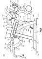
- a leg curl exercise machine 100includes a stationary main frame 110.
- the main frame 110is a fixed frame structure and includes a horizontal side strut 1 11 ; a horizontal cross strut 1 12; support uprights 1 13, 1 14; a vertical exercise arm support member 1 15, and a horizontal connecting strut 116.
- the main frame 110also includes support feet 117 at both ends of the horizontal side strut 1 1 1 and at the end of the horizontal cross strut 1 12.
- the main frame 1 10includes a thigh pad frame 1 18 on which a thigh pad 1 19 is mounted.
- the main frame 1 10further includes, a weight stack support strut 120 ( FIG. 2 ), an exercise arm support strut 121 ( FIG. 2 ), moving support frame pivot brackets 122, 123 ( FIGS. 2-4 ), an exercise arm pivot bracket 124 ( FIGS. 1 and 3 ), and a pivot sleeve 125 ( FIGS. 2 and 4 ).
- the main frame 1 10supports the weight of the user and provides a fixed structure to which all moving assemblies are connected.
- the leg curl exercise machine 100further includes a moving support frame 130 that supports the user's upper torso during performance of a prone leg curl exercise.
- the moving support frame 130is a frame structure or platform that includes a moving frame member 131, a chest pad 132, and a pair of handles 133.
- the handles 133are positioned forward of the chest pad 132 and angled downwardly and outwardly.
- the moving frame member 131includes an axle 134 for pivotally connecting the moving support frame 130 to the connecting link 160, which is further described below.
- the axle 134comprises a shaft passing through the frame member 131 and welded into place.
- the moving support frame 130further includes a counterweight 135 connected to the moving frame member 131 at an end opposite the chest pad 132 and handles 133.
- the counterweight 135balances the moving support frame 130.
- the counterweight 135may also lightly bias the moving support frame 130 toward an exercise starting position, which is described in further detail below.
- the moving support frame 130is pivotally connected to the main frame 1 10.
- the moving support frame 130includes a pivot strut 136 connecting the moving frame member 131 to a pivot sleeve 137.
- a pivot pin 138passes through moving support frame pivot brackets 122, 123 on the main frame 1 10 and through the pivot sleeve 137.
- the moving support frame 130is thus pivotally connected to the main frame 1 10 for rotation about pivot axis 139 ( FIGS. 3 and 4 ).
- the leg curl exercise machine 100further includes an exercise arm assembly 140.
- the exercise arm assembly 140includes a rotating exercise arm 141, and at least one roller pad 142.
- the rotating exercise arm 141has a pivot sleeve 143 and a pull pin 144 that allows a user to adjust the position and orientation of the exercise arm assembly 140 in the exercise starting position, which is described in further detail below.
- the rear end of the rotating exercise arm 141has a roller pad support and pivot bracket 145.
- a roller pad support rod 146is connected to the roller pad support and pivot bracket 145 and provides support and mounting for the roller pad 142.
- the opposite, front end of the rotating exercise arm 141has a counterweight 147 that balances the exercise arm assembly 140, so that its position and orientation may be more easily adjusted.
- the exercise arm assembly 140 and the cam assembly 150are both pivotally connected to the main frame 110.
- a pivot pin 148passes through the exercise arm pivot bracket 124 and the pivot sleeve 125 on the main frame 1 10, through the pivot sleeve 143 on the rotating exercise arm 141 of the exercise arm assembly 140, and through the opening 152 in the cam 151 of the cam assembly 150.
- the exercise arm assembly 140 and the cam assembly 150are pivotally connected to the main frame 1 10 for independent rotation about pivot axis 149 ( FIGS. 3 and 4 ).
- the exercise arm assembly 140 and the cam assembly 150are pivotally connected for independent rotation about a common pivot axis 149, the pull pin 144 and the adjustment openings 154 in the exercise arm adjuster 153 allow the exercise arm assembly 140 and cam assembly 150 to be selectively coupled together at various orientations for synchronized rotation about pivot axis 149.
- a usermay select from among the adjustment openings 154 and selectively engage or release the pull pin 144 into one or more of the adjustment openings 154 in order to couple the exercise arm assembly 140 to the cam assembly 150. Once coupled, the exercise arm assembly 140 and the cam assembly 150 will rotate together about pivot axis 149.
- the various adjustment openings 154allow the user to couple the exercise arm assembly 140 to the cam assembly 150 when the exercise arm assembly 140 is in a preferred position and orientation for starting an exercise. That is, the user may engage or release the pull pin 144 into one or more adjustment openings 154 in order to adjust the position and orientation of the exercise arm assembly 140, so that the exercise arm assembly 140, specifically the roller pad 142, is in a preferred position and orientation for the exercise starting position.
- the leg curl exercise machine 100 of FIGS. 1-10further includes a connecting link 160.
- the connecting link 160includes a bent member 161 with pivot sleeves 162, 163 on each end thereof.
- the pivot sleeve 162 at one end of the bent member 161is pivotally connected to the moving frame member 131 at axle 134.
- the axle 134passes through pivot sleeve 162, pivotally connecting the connecting link 160 to the moving support frame 130 for relative rotation about pivot axis 166 ( FIGS. 3 and 4 ).
- the pivot sleeve 163 at the opposite end of the bent member 161is pivotally connected to the cam 151 at its axle 155.
- the axle 155passes through pivot sleeve 163, pivotally connecting the connecting link 160 to the cam assembly 150 for relative rotation about pivot axis 167 ( FIGS. 3 and 4 ).
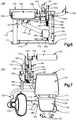
- the leg curl exercise machine 100further includes a source of resistance, which in the case of the embodiment depicted in FIGS. 1-10 is a selectorized weight stack assembly 170.
- a source of resistancewhich in the case of the embodiment depicted in FIGS. 1-10 is a selectorized weight stack assembly 170.
- the source of resistancemay include, without limitation, a weight stack, weight plates mounted on pegs, or other types of resistance such as hydraulic, pneumatic, electromagnetic, friction, springs, elastically bending rods, elastic bands, or the like.
- the selectorized weight stack assembly 170is connected to the main frame 1 10 at the ends of horizontal connecting strut 1 16 and weight stack support strut 120.
- the selectorized weight stack assembly 170includes a lifting rod 171 operatively connected to a cable (not shown), a plurality of weight plates 172 which are slidingly mounted on guide rods 173 (only one shown) and a housing 174.
- Lifting rod 171 and weight plates 172have aligned openings 175 through which a pin 176 can be inserted to connect weight plates 172 to lifting rod 171.
- the leg curl exercise machine 100 depicted in FIGS. 1-10further includes a pulley assembly 180 that transmits the resistance provided by the selectorized weight stack assembly 170 to the exercise arm assembly 140, biasing the exercise arm assembly 140 toward an exercise starting position.
- the pulley assembly 180includes a cable (not shown) anchored at a first end to the cam 151. The cable extends around a first pulley 181 mounted on the vertical exercise arm support member 115 and a second pulley 182 mounted on the horizontal cross strut 112. The cable then extends through a hollow in the horizontal cross strut 1 12 and around a third pulley 183 mounted on the horizontal connecting strut 116.
- the cablethen extends through a hollow in the horizontal connecting strut 1 16 and its second end is directly or indirectly connected to the lifting rod 171 of the selectorized weight stack assembly 170.
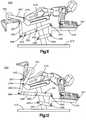
- FIG. 9shows the depicted embodiment in an exercise starting position, with a user prepared to perform a prone leg curl exercise.
- the useris in a face-down, prone position with his thighs engaging and being supported by the thigh pad 119, which is mounted to the main frame 110.
- the user's upper torsois supported by the chest pad 132 and the handles 133.
- the backs of the user's lower legsengage the roller pad 142.
- the exercise arm assembly 140may be adjusted to achieve a preferred position and orientation for the exercise starting position of the roller pad 142. Accordingly, when performing a prone leg curl exercise, the exercise arm assembly 140 is coupled to the cam assembly 150, as previously described.
- the userbegins by using his lower legs to exert a force on the roller pad 142.
- the roller pad 142moves upwardly and forwardly in an arcuate path as the exercise arm assembly 140 and the cam assembly 150 rotate together about pivot axis 149 ( FIGS. 3 and 4 ).
- the cam 151rotates about pivot axis 149, it lifts connecting link 160, which is pivotally connected to the cam 151 at pivot axis 167.
- the connecting link 160moves upward, it lifts the rear (counterweighted) end of moving frame member 131, which is pivotally connected to the connecting link at pivot axis 166.
- the entire moving support frame 130tilts as it rotates about pivot axis 139.
- the front end of the moving support frame 130dips lower as the user completes a prone leg curl exercise, finishing in the exercise ending position shown in FIG. 10 .
- the user's upper torsomoves downward as the chest pad 132 and handles 133 dip lower, thus avoiding any excessive arching or stressing of the user's lower back.
- the cam 151pulls on the cable (not shown) of the pulley assembly 180, which is connected to the selectorized weight stack assembly 170.
- the counterweights 135, 147balance the respective moving assemblies, i.e. the moving support frame 130 and the exercise arm assembly 140. Accordingly, the amount of resistance that biases the exercise arm assembly 140 toward the exercise starting position is almost entirely determined by the amount of weight selected in the selectorized weight stack assembly 170. That is, the user experiences substantially zero additional resistance throughout the exercise motion.
- FIGS. 1 1 and 12depict an additional embodiment of the present invention.
- FIG. 1 1shows a leg curl exercise machine 200 in an exercise starting position
- FIG. 12shows the embodiment in an exercise ending position.
- the embodiment of FIGS. 1 1 and 12includes a main frame 210 supporting a stationary thigh pad 219.
- An exercise arm assembly 240includes a roller pad 242 and is pivotally mounted to the main frame 210 for rotation about pivot axis 249.
- the exercise arm assembly 240is pivotally connected to a connecting link 260 for relative rotation about pivot axis 267.
- the exercise arm assembly's 240 pivotal connection to the connecting link 260may be direct, or alternatively, it may be indirect using an intervening cam assembly such as the cam assembly 150 previously described.
- the connecting link 260is pivotally connected to a first member 291 for relative rotation about pivot axis 266.
- the first member 291is pivotally connected to the main frame 210 for rotation about pivot axis 292, which is forward of pivot axis 266.
- the first member 291is also pivotally connected to a moving support frame 230 at a location forward of pivot axis 292, for relative rotation about pivot axis 293.
- a second member 294is pivotally connected to the main frame 210 for rotation about pivot axis 295.
- the second member 294is also pivotally connected to the moving support frame 230 at a location forward of the pivot axis 295, for relative rotation about pivot axis 296.
- the main frame 210, first member 291, moving support frame 230, and second member 294together form a four-bar linkage 290.
- the moving support frame 230is depicted in FIGS. 1 1 and 12 as including an arm rest pad 297. But those skilled in the art will appreciate that this embodiment may also utilize one or more chest pads, handles, or other means of supporting the user's upper torso that are understood in the art.
- the user's lower legsexert a force on the roller pad 242.
- the roller pad 242moves upwardly and forwardly in an arcuate path as the exercise arm assembly 240 rotates about pivot axis 249.
- connecting link 260which is pivotally connected to the exercise arm assembly (or to a cam assembly such as cam assembly 150) at pivot axis 267, is pulled upward.
- the connecting link 260moves upward, it lifts the rear end of first member 291, which is pivotally connected to the connecting link at pivot axis 266.
- first member 291As the rear end of first member 291 moves upward, it tilts about pivot axis 292, such that the front end of first member 291 moves downward. As the front end of first member 291 moves downward, the front end of second member 294 and the moving support frame 230 also move downward because the moving support frame 230 and the front ends of the first and second members 291 , 294 are all coupled together through pivot axes 293, 296.
- the moving support frame 230dips lower as the user completes a prone leg curl exercise, finishing in the exercise ending position shown in FIG. 12 .
- the user's upper torsomoves downward as the arm rest pad 297 dips lower, thus avoiding any excessive arching or stressing of the user's lower back.
- FIGS. 13 and 14depict an additional embodiment of the present invention.
- FIG. 13shows a leg curl exercise machine 300 in an exercise starting position
- FIG. 14shows the embodiment in an exercise ending position.
- the embodiment of FIGS. 13 and 14includes a main frame 310 supporting a tilting thigh pad frame 318 that is pivotally connected to the main frame for rotation about pivot axis 320.
- a thigh pad 319is mounted on the tilting thigh pad frame 318.
- An exercise arm assembly 340includes a roller pad 342 and is pivotally mounted to the tilting thigh pad frame 318 for relative rotation about pivot axis 349.
- the exercise arm assembly 340is pivotally connected to a connecting link 360 for relative rotation about pivot axis 367.
- the exercise arm assembly's 340 pivotal ⁇ '>connection to the connecting link 360may be direct, or alternatively, it may be indirect using an intervening cam assembly such as the cam assembly 150 previously described.
- the connecting link 360is pivotally connected to the main frame 310 for rotation about pivot axis 366.
- a moving support frame 330is pivotally connected to the tilting thigh pad frame 318 for relative rotation about pivot axis 339.
- the moving support frame 330is pivotally connected to a second connecting link 370 for relative rotation about pivot axis 377.
- the second connecting link 370is pivotally connected to the main frame 310 for relative rotation about pivot axis 376.
- the moving support frame 330is depicted in FIGS. 13 and 14 as including an arm rest pad 397. But those skilled in the art will appreciate that this embodiment may also utilize one or more chest pads, handles, or other means of supporting the user's upper torso that are understood in the art.
- the user's lower legsexert a force on the roller pad 342.
- the roller pad 342moves upwardly and forwardly in an arcuate path as the exercise arm assembly 340 rotates.
- an exercise arm assemblyrotates about a fixed pivot axis, pulling a connecting link upward.
- the connecting link 360 of the leg curl exercise machine 300cannot move upward because it is pivotally connected to the main frame 310 for rotation about pivot axis 366.
- exercise arm assembly 340rotates about pivot axes 349 and 367, which both move relative to the main frame 310. Pivot axis 349 moves downward, along with the rear end of the tilting thigh pad frame 318.
- the tilting thigh pad frame 318thus tilts as it rotates about pivot axis 320. Accordingly, the front end of the tilting thigh pad frame 318 moves upward. As the front end of the tilting thigh pad frame 318 moves upward, it lifts and draws rearward the rear end of moving support frame 330, which is pivotally coupled to the tilting thigh pad frame 318 for relative rotation about pivot axis 339. As the rear end of the moving support frame 330 moves rearward, the second connecting link 370, which is pivotally connected to the moving support frame 330 for rotation about pivot axis 377, rotates about pivot axis 376. This causes the front end of the moving support frame 330 to rise.
- the tilting thigh pad frame 318 and thigh pad 319tilt as the user completes a prone leg curl exercise, finishing in the exercise ending position shown in FIG. 14 .
- the moving support frame 330including the arm rest pad 397, moves in an upward and rearward direction while also tilting slightly to end in the exercise ending position of FIG. 14 .
- the user's thighs, lower torso, and upper torsomove in such a way as to avoid any excessive arching or stressing of the user's lower back.
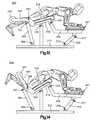
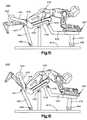
- FIGS. 15 and 16depict an additional embodiment of the present invention.
- FIG. 15shows a leg curl exercise machine 400 in an exercise starting position
- FIG. 16shows the embodiment in an exercise ending position.
- the embodiment of FIGS. 15 and 16is substantially similar to the embodiment of FIGS. 13 and 14 , except that the moving support frame 430 is rigidly connected to a second connecting link 470 that includes a roller 490 that engages the main frame 410.
- the embodiment shown in FIGS. 13 and 14includes a second connecting link 370 pivotally connected to the main frame 310 for rotation about pivot axis 376 and to the moving support frame 330 for rotation about pivot axis 377.
- FIGS. 15 and 16includes a main frame 410 supporting a tilting thigh pad frame 418 that is pivotally connected to the main frame 410 for rotation about pivot axis 420.
- a thigh pad 419is mounted on the tilting thigh pad frame 418.
- An exercise arm assembly 440includes a roller pad 442 and is pivotally mounted to the tilting thigh pad frame 418 for relative rotation about pivot axis 449.
- the exercise arm assembly 440is pivotally connected to a connecting link 460 for relative rotation about pivot axis 467.
- the exercise arm assembly's 440 pivotal connection to the connecting link 460may be direct, or alternatively, it may be indirect using an intervening cam assembly such as the cam assembly 150 previously described.
- the connecting link 460is pivotally connected to the main frame 410 for rotation about pivot axis 466.
- a moving support frame 430is pivotally connected to the tilting thigh pad frame 418 for relative rotation about pivot axis 439.
- the moving support frame 430is rigidly connected to a second connecting link 470.
- the second connecting link 470includes a roller 490 that engages the main frame 410 to allow the moving support frame 430 to move fore and aft and rotate relative to the main frame 410.
- the second connecting link 470may slide along a surface on the main frame 410.
- Other means of enabling the desired movement between the moving support frame 430 and the main frame 410will be readily apparent to those skilled in the art.
- the moving support frame 430is depicted in FIGS. 15 and 16 as including an arm rest pad 497. But those skilled in the art will appreciate that this embodiment may also utilize one or more chest pads, handles, or other means of supporting the user's upper torso that are understood in the art.
- the user's lower legsexert a force on the roller pad 442.
- the roller pad 442moves upwardly and forwardly in an arcuate path as the exercise arm assembly 440 rotates.
- the exercise arm assembly 440rotates about pivot axes 449 and 467, which both move relative to the main frame 410.
- Pivot axis 449moves downward, along with the rear end of the tilting thigh pad frame 418.
- the tilting thigh pad frame 418thus tilts as it rotates about pivot axis 420. Accordingly, the front end of the tilting thigh pad frame 418 moves upward.
- the tilting thigh pad frame 418As the front end of the tilting thigh pad frame 418 moves upward, it lifts and draws rearward the rear end of moving support frame 430, which is pivotally coupled to the tilting thigh pad frame 418 for relative rotation about pivot axis 439. As the rear end of the moving support frame 430 moves rearward, the second connecting link 470, which is rigidly connected to the moving support frame 430, moves rearward as well. This causes the roller 490 to travel rearward along the main frame 410.
- the tilting thigh pad frame 418 and thigh pad 419tilt as the user completes a prone leg curl exercise, finishing in the exercise ending position shown in FIG. 16 .
- the moving support frame 430including the arm rest pad 497, moves in an upward and rearward direction while also tilting slightly to end in the exercise ending position of FIG. 16 .
- the user's thighs, lower torso, and upper torsomove in such a way as to avoid any excessive arching of the lower back.
- leg curl exercise machine180 - pulley assembly 110- main frame 181 - first pulley 111 - horizontal side strut 182 - second pulley 112 - horizontal cross strut 183 - third pulley 113 - support upright 200 - leg curl exercise machine 114 - support upright 210 - main frame 115 - vertical exercise arm support member 219 - stationary thigh pad 116 - horizontal connecting strut 230 - moving support frame 117 - support foot 240 - exercise arm assembly 118 - thigh pad frame 242 - roller pad 119 - thigh pad 249 - pivot axis 120 - weight stack support strut 260 - connecting link 121 - exercise arm support strut 266 - pivot axis 122 - moving support frame pivot bracket 267 - pivot axis 123 - moving support frame pivot bracket 290 - four-bar linkage 124 - exercise arm pivot bracket 291 - first member
Landscapes
- Health & Medical Sciences (AREA)
- Orthopedic Medicine & Surgery (AREA)
- Physical Education & Sports Medicine (AREA)
- General Health & Medical Sciences (AREA)
- Biophysics (AREA)
- Life Sciences & Earth Sciences (AREA)
- Neurology (AREA)
- Biomedical Technology (AREA)
- Engineering & Computer Science (AREA)
- Pulmonology (AREA)
- Cardiology (AREA)
- Vascular Medicine (AREA)
- Rehabilitation Tools (AREA)
Description
- The present invention generally relates to fitness equipment. Specifically, the embodiments of the present invention are directed to an exercise machine for performing prone leg curl exercises, including a moving support platform or frame that allows a user to perform prone leg curl exercises without excessively arching his or her lower back.
- Traditional leg curl exercise machines include a stationary platform or frame for supporting the user's upper torso while the user performs prone leg curl exercises. These traditional leg curl exercise machines support the upper torso in a relatively fixed position while the user's lower legs move in an arcuate path from an exercise starting position to an exercise ending position (and often back to the exercise start position). Because the traditional leg curl exercise machine supports the user's upper torso in a relatively fixed position, the movement associated with the user's lower body often results in excessive arching of the lower back, particularly when the user's lower legs are in the exercise ending position. Excessive arching of the lower back can lead to lower back pain, strain, or other associated injury.
- Consequently, a need exists for a leg curl exercise machine that maintains the user's body in a more ergonomically sound position throughout the exercise motion. The embodiments of the present invention solve this problem by providing a leg curl exercise machine that includes a moving support platform or frame to support the user's upper torso. The moving support platform or frame may include a linkage assembly that allows the moving support platform or frame to tilt as the user performs a prone leg curl exercise. Other advantages of the present invention will become apparent to one skilled in the art.
- For example
US 2008/058177 A1 discloses an isolation exercise machine for exercising one muscle group having a user support which is pivotally mounted on a main frame by a pivotal mounting system. A user engaging exercise arm is pivotally connected to the user support, and a connecting link links movement of the user exercise arm to movement in the user support. A load provides resistance to movement of the user support, exercise arm and/or connecting link. The pivotal mounting system is configured to place the user support seat in a relatively flat position in the rest or exercise start position and to recline and change the seat angle to an inclined position as the exercise arm is moved. - The present invention defines a leg curl exercise machine for performing prone leg curl exercises according to claim 1. Preferred embodiments are defined in the dependent claims.
- A disclosure is directed to an exercise machine for performing prone leg curl exercises, the exercise machine including a main frame coupled to a stationary thigh pad; an exercise arm pivotally connected to the main frame that moves in an arcuate path from an exercise starting position to an exercise ending position; a source of resistance associated with the exercise arm, which may be a selectorized weight stack assembly and which biases the exercise arm toward the exercise starting position; a moving support platform pivotally connected to the main frame that is configured to support a user's upper torso, which may include a chest pad; and a connecting link assembly pivotally connected to the exercise arm and to the moving support platform or frame, which may be a four-bar linkage and which translates movement of the exercise arm into a tilting or lowering movement of the moving support platform.
- Another disclosure is directed to an exercise machine for performing prone leg curl exercises, the exercise machine including a main frame coupled to a stationary thigh pad; an exercise arm pivotally connected to the main frame that moves in an arcuate path from an exercise starting position to an exercise ending position; a source of resistance associated with the exercise arm, which may be a selectorized weight stack assembly and which biases the exercise arm toward the exercise starting position; a moving support frame pivotally connected to the main frame that is configured to support a user's upper torso, which may include an arm rest support frame; and a connecting link assembly pivotally connected to the main frame, to the exercise arm, and to the moving support platform or frame, which may be a four-bar linkage and which translates movement of the exercise arm into a tilting or lowering movement of the moving support frame.
- Yet another disclosure is directed to an exercise machine for performing prone leg curl exercises, the exercise machine including a main frame pivotally connected to a moving thigh support; an exercise arm pivotally connected to the moving thigh support that moves in an arcuate path from an exercise starting position to an exercise ending position; a source of resistance associated with the exercise arm, which may be a selectorized weight stack assembly and which biases the exercise arm toward the exercise starting position; a moving support frame pivotally connected to the moving thigh support that is configured to support a user's upper torso, which may include an arm rest support frame; a connecting link assembly pivotally connecting the exercise arm to the main frame; and a connecting link assembly pivotally connecting the moving support frame to the main frame.
- Yet another disclosure is directed to an exercise machine for performing prone leg curl exercises, the exercise machine including a main frame pivotally connected to a moving thigh support; an exercise arm pivotally connected to the moving thigh support that moves in an arcuate path from an exercise starting position to an exercise ending position; a source of resistance associated with the exercise arm, which may be a selectorized weight stack assembly and which biases the exercise arm toward the exercise starting position; a moving support frame pivotally connected to the moving thigh support that is configured to support a user's upper torso, which may include an arm rest support frame; a connecting link assembly pivotally connecting the exercise arm to the main frame; and a support roller assembly connecting the moving support frame to the main frame for a sliding, fore-aft movement.
- Preferred features of the embodiments of the present invention are disclosed in the accompanying drawings, wherein similar reference characters denote similar elements throughout the several views, and wherein:
FIG. 1 is an isometric, left-hand view of a leg curl exercise machine including a selectorized weight stack assembly.FIG. 2 is an isometric, right-hand view of a leg curl exercise machine as depicted inFIG. 1 , with the selectorized weight stack assembly omitted for clarity.FIG. 3 is a left side view of a leg curl exercise machine as depicted inFIG. 1 , with the selectorized weight stack assembly omitted for clarity.FIG. 4 is a right side view of a leg curl exercise machine as depicted inFIG. 1 , with the selectorized weight stack assembly omitted for clarity.FIG. 5 is a front side view of a leg curl exercise machine as depicted inFIG. 1 , with the selectorized weight stack assembly omitted for clarity.FIG. 6 is a back side view of a leg curl exercise machine as depicted inFIG. 1 , with the selectorized weight stack assembly omitted for clarity.FIG. 7 is a top view of a leg curl exercise machine as depicted inFIG. 1 , including the selectorized weight stack assembly.FIG. 8 is a bottom view of a leg curl exercise machine as depicted inFIG. 1 , including the selectorized weight stack assembly.FIG. 9 is a left side view of a leg curl exercise machine as depicted inFIG. 1 , including a user in the exercise starting position, with the selectorized weight stack assembly omitted for clarity.FIG. 10 is a left side view of a leg curl exercise machine as depicted inFIG. 1 , including a user in the exercise ending position, with the selectorized weight stack assembly omitted for clarity.FIG. 11 is a right side view of an alternative embodiment of a leg curl exercise machine, including a user in the exercise starting position, with the selectorized weight stack assembly omitted for clarity.FIG. 12 is a right side view of an alternative embodiment of a leg curl exercise machine as depicted inFIG. 11 , including a user in the exercise ending position, with the selectorized weight stack assembly omitted for clarity.FIG. 13 is a right side view of an alternative embodiment of a leg curl exercise machine, including a user in the exercise starting position, with the selectorized weight stack assembly omitted for clarity.FIG. 14 is a right side view of an alternative embodiment of a leg curl exercise machine as depicted inFIG. 13 , including a user in the exercise ending position, with the selectorized weight stack assembly omitted for clarity.FIG. 15 is a right side view of an alternative embodiment of a leg curl exercise machine, including a user in the exercise starting position, with the selectorized weight stack assembly omitted for clarity.FIG. 16 is a right side view of an alternative embodiment of a leg curl exercise machine as depicted inFIG. 15 , including a user in the exercise ending position, with the selectorized weight stack assembly omitted for clarity.- The embodiments of the present invention will now be described more fully hereinafter with reference to the accompanying drawings, in which preferred embodiments of the invention are shown. This invention may, however, be embodied in many different forms and should not be construed as limited to the illustrated embodiments set forth herein. Rather, these illustrated embodiments are provided so that this disclosure will be thorough and complete and will convey the scope of the invention defined by the appended claims to those skilled in the art.
- In the following description, like reference characters designate like or corresponding parts throughout the figures. It is to be understood that the phraseology and terminology used in the following description are used for the purpose of description and enablement, and should not be regarded as limiting. Additionally, in the following description, it is understood that terms such as "top," "bottom," "side," "front," "back," "inner," "outer," and the like, are words of convenience and are not to be construed as limiting terms.
- A leg curl exercise machine including a moving support for performing prone leg curl exercises is described herein. The embodiments of the present invention are designed to provide a leg curl exercise machine that avoids excessive arching of the lower back by maintaining the user's body in a more economically sound position throughout the exercise motion when a user performs prone leg curl exercises.
- An embodiment of the present invention includes a leg
curl exercise machine 100 as depicted inFIGS. 1-10 . As best shown inFIGS. 1 and2 , a legcurl exercise machine 100 includes a stationarymain frame 110. Themain frame 110 is a fixed frame structure and includes a horizontal side strut 1 11 ; a horizontal cross strut 1 12; support uprights 1 13, 1 14; a vertical exercise arm support member 1 15, and a horizontal connectingstrut 116. Themain frame 110 also includessupport feet 117 at both ends of the horizontal side strut 1 1 1 and at the end of the horizontal cross strut 1 12. The main frame 1 10 includes a thigh pad frame 1 18 on which a thigh pad 1 19 is mounted. The main frame 1 10 further includes, a weight stack support strut 120 (FIG. 2 ), an exercise arm support strut 121 (FIG. 2 ), moving supportframe pivot brackets 122, 123 (FIGS. 2-4 ), an exercise arm pivot bracket 124 (FIGS. 1 and3 ), and a pivot sleeve 125 (FIGS. 2 and4 ). The main frame 1 10 supports the weight of the user and provides a fixed structure to which all moving assemblies are connected. - The leg
curl exercise machine 100, as depicted inFIGS. 1-10 , further includes a movingsupport frame 130 that supports the user's upper torso during performance of a prone leg curl exercise. Themoving support frame 130 is a frame structure or platform that includes a movingframe member 131, achest pad 132, and a pair ofhandles 133. Thehandles 133 are positioned forward of thechest pad 132 and angled downwardly and outwardly. The movingframe member 131 includes anaxle 134 for pivotally connecting themoving support frame 130 to the connectinglink 160, which is further described below. Theaxle 134 comprises a shaft passing through theframe member 131 and welded into place. However, one skilled in the art will recognize that alternative methods of providing a pivotal connection may be used, and these alternative methods are within the scope of the present invention. The movingsupport frame 130 further includes acounterweight 135 connected to the movingframe member 131 at an end opposite thechest pad 132 and handles 133. Thecounterweight 135 balances themoving support frame 130. Thecounterweight 135 may also lightly bias the movingsupport frame 130 toward an exercise starting position, which is described in further detail below. - As shown in
FIGS. 2 and3 , the movingsupport frame 130 is pivotally connected to the main frame 1 10. The movingsupport frame 130 includes apivot strut 136 connecting the movingframe member 131 to apivot sleeve 137. Apivot pin 138 passes through moving supportframe pivot brackets pivot sleeve 137. The movingsupport frame 130 is thus pivotally connected to the main frame 1 10 for rotation about pivot axis 139 (FIGS. 3 and4 ). - The leg
curl exercise machine 100, as depicted inFIGS. 1-10 , further includes anexercise arm assembly 140. Theexercise arm assembly 140 includes arotating exercise arm 141, and at least oneroller pad 142. Therotating exercise arm 141 has apivot sleeve 143 and apull pin 144 that allows a user to adjust the position and orientation of theexercise arm assembly 140 in the exercise starting position, which is described in further detail below. The rear end of therotating exercise arm 141 has a roller pad support andpivot bracket 145. A rollerpad support rod 146 is connected to the roller pad support andpivot bracket 145 and provides support and mounting for theroller pad 142. The opposite, front end of therotating exercise arm 141 has acounterweight 147 that balances theexercise arm assembly 140, so that its position and orientation may be more easily adjusted. - The leg
curl exercise machine 100 ofFIGS. 1-10 further includes acam assembly 150 associated with theexercise arm assembly 140. Thecam assembly 150 includes acam 151 pivotally mounted on the main frame 1 10. Thecam 151 has anopening 152 for pivotally mounting thecam assembly 150 to the main frame 1 10. Thecam 151 has anexercise arm adjuster 153 withadjustment openings 154 that provide selective adjustment of the position and orientation of theexercise arm assembly 140. Thecam 151 also includes anaxle 155 for pivotally connecting thecam assembly 150 to the connectinglink 160, which is further described below. Theaxle 155 comprises a shaft passing through thecam 151 and welded into place. However, one skilled in the art will recognize that alternative methods of providing a pivotal connection may be used, and these alternative methods are within the scope of the present invention defined by the appended claims. - As shown in
FIGS. 1-4 , theexercise arm assembly 140 and thecam assembly 150 are both pivotally connected to themain frame 110. Apivot pin 148 passes through the exercisearm pivot bracket 124 and thepivot sleeve 125 on the main frame 1 10, through thepivot sleeve 143 on therotating exercise arm 141 of theexercise arm assembly 140, and through theopening 152 in thecam 151 of thecam assembly 150. Thus, theexercise arm assembly 140 and thecam assembly 150 are pivotally connected to the main frame 1 10 for independent rotation about pivot axis 149 (FIGS. 3 and4 ). - Though the
exercise arm assembly 140 and thecam assembly 150 are pivotally connected for independent rotation about acommon pivot axis 149, thepull pin 144 and theadjustment openings 154 in theexercise arm adjuster 153 allow theexercise arm assembly 140 andcam assembly 150 to be selectively coupled together at various orientations for synchronized rotation aboutpivot axis 149. A user may select from among theadjustment openings 154 and selectively engage or release thepull pin 144 into one or more of theadjustment openings 154 in order to couple theexercise arm assembly 140 to thecam assembly 150. Once coupled, theexercise arm assembly 140 and thecam assembly 150 will rotate together aboutpivot axis 149. Additionally, thevarious adjustment openings 154 allow the user to couple theexercise arm assembly 140 to thecam assembly 150 when theexercise arm assembly 140 is in a preferred position and orientation for starting an exercise. That is, the user may engage or release thepull pin 144 into one ormore adjustment openings 154 in order to adjust the position and orientation of theexercise arm assembly 140, so that theexercise arm assembly 140, specifically theroller pad 142, is in a preferred position and orientation for the exercise starting position. - As best shown in
FIGS. 1-4 , the legcurl exercise machine 100 ofFIGS. 1-10 further includes a connectinglink 160. The connectinglink 160 includes abent member 161 withpivot sleeves pivot sleeve 162 at one end of thebent member 161 is pivotally connected to the movingframe member 131 ataxle 134. Theaxle 134 passes throughpivot sleeve 162, pivotally connecting the connectinglink 160 to the movingsupport frame 130 for relative rotation about pivot axis 166 (FIGS. 3 and4 ). Similarly, thepivot sleeve 163 at the opposite end of thebent member 161 is pivotally connected to thecam 151 at itsaxle 155. Theaxle 155 passes throughpivot sleeve 163, pivotally connecting the connectinglink 160 to thecam assembly 150 for relative rotation about pivot axis 167 (FIGS. 3 and4 ). - The leg
curl exercise machine 100 further includes a source of resistance, which in the case of the embodiment depicted inFIGS. 1-10 is a selectorizedweight stack assembly 170. One of ordinary skill in the art will appreciate, however, that the source of resistance may include, without limitation, a weight stack, weight plates mounted on pegs, or other types of resistance such as hydraulic, pneumatic, electromagnetic, friction, springs, elastically bending rods, elastic bands, or the like. The selectorizedweight stack assembly 170 is connected to the main frame 1 10 at the ends of horizontal connecting strut 1 16 and weightstack support strut 120. The selectorizedweight stack assembly 170 includes a liftingrod 171 operatively connected to a cable (not shown), a plurality ofweight plates 172 which are slidingly mounted on guide rods 173 (only one shown) and ahousing 174. Liftingrod 171 andweight plates 172 have alignedopenings 175 through which apin 176 can be inserted to connectweight plates 172 to liftingrod 171. When a selectedweight plate 172 is connected to liftingrod 171, the selectedweight plate 172, and any weight plates above the selectedweight plate 172, will be lifted with the liftingrod 171. - The leg
curl exercise machine 100 depicted inFIGS. 1-10 further includes apulley assembly 180 that transmits the resistance provided by the selectorizedweight stack assembly 170 to theexercise arm assembly 140, biasing theexercise arm assembly 140 toward an exercise starting position. In the depicted embodiment, thepulley assembly 180 includes a cable (not shown) anchored at a first end to thecam 151. The cable extends around afirst pulley 181 mounted on the vertical exercisearm support member 115 and asecond pulley 182 mounted on thehorizontal cross strut 112. The cable then extends through a hollow in the horizontal cross strut 1 12 and around athird pulley 183 mounted on the horizontal connectingstrut 116. The cable then extends through a hollow in the horizontal connecting strut 1 16 and its second end is directly or indirectly connected to the liftingrod 171 of the selectorizedweight stack assembly 170. Thus, when theexercise arm assembly 140 and thecam assembly 150 are coupled to rotate together, movement of theexercise arm assembly 140 from the exercise starting position to the exercise ending position, as described below, causes the cable (not shown) of thepulley assembly 180 to pull the liftingrod 171 of the selectorizedweight stack assembly 170, which in turn lifts the selectedweight plate 172 and any weight plates above the selectedweight plate 172. - The operation and use of the embodiment depicted in
FIGS. 1-10 will now be described with specific reference toFIGS. 9 and 10. FIG. 9 shows the depicted embodiment in an exercise starting position, with a user prepared to perform a prone leg curl exercise. The user is in a face-down, prone position with his thighs engaging and being supported by thethigh pad 119, which is mounted to themain frame 110. The user's upper torso is supported by thechest pad 132 and thehandles 133. The backs of the user's lower legs engage theroller pad 142. As described above, theexercise arm assembly 140 may be adjusted to achieve a preferred position and orientation for the exercise starting position of theroller pad 142. Accordingly, when performing a prone leg curl exercise, theexercise arm assembly 140 is coupled to thecam assembly 150, as previously described. - The user begins by using his lower legs to exert a force on the
roller pad 142. In response, theroller pad 142 moves upwardly and forwardly in an arcuate path as theexercise arm assembly 140 and thecam assembly 150 rotate together about pivot axis 149 (FIGS. 3 and4 ). As thecam 151 rotates aboutpivot axis 149, it lifts connectinglink 160, which is pivotally connected to thecam 151 atpivot axis 167. As the connectinglink 160 moves upward, it lifts the rear (counterweighted) end of movingframe member 131, which is pivotally connected to the connecting link atpivot axis 166. As the rear end of movingframe member 131 moves upward, the entire movingsupport frame 130 tilts as it rotates aboutpivot axis 139. Thus, the front end of the movingsupport frame 130, including thechest pad 132 and handles 133, dips lower as the user completes a prone leg curl exercise, finishing in the exercise ending position shown inFIG. 10 . As shown inFIG. 10 , the user's upper torso moves downward as thechest pad 132 and handles 133 dip lower, thus avoiding any excessive arching or stressing of the user's lower back. - As described with more detail above, as the
exercise arm assembly 140 and thecam assembly 150 rotate together aboutpivot axis 149, thecam 151 pulls on the cable (not shown) of thepulley assembly 180, which is connected to the selectorizedweight stack assembly 170. Furthermore, thecounterweights support frame 130 and theexercise arm assembly 140. Accordingly, the amount of resistance that biases theexercise arm assembly 140 toward the exercise starting position is almost entirely determined by the amount of weight selected in the selectorizedweight stack assembly 170. That is, the user experiences substantially zero additional resistance throughout the exercise motion. - Additional embodiments of the present invention include leg curl exercise machines such as those depicted in
FIGS. 1 1 and12 , inFIGS. 13 and 14 , and inFIGS. 15 and 16 . One of ordinary skill in the art will appreciate thatFIGS. 11-16 and the accompanying descriptions are simplified to convey and enable the basic structure and operation of these embodiments, in light of the detailed description and drawings already provided with respect to the embodiment ofFIGS. 1-10 . The embodiments ofFIGS. 11-16 may include any or all of the components and features described and depicted with respect to the embodiment ofFIGS. 1-10 . The present invention encompasses all such variations. Accordingly, the description of the embodiment ofFIGS. 1-10 is expressly incorporated with respect to each of the embodiments shown inFIGS. 11 and 12 , inFIGS. 13 and 14 , and inFIGS. 15 and 16 . FIGS. 1 1 and12 depict an additional embodiment of the present invention.FIG. 1 1 shows a legcurl exercise machine 200 in an exercise starting position, andFIG. 12 shows the embodiment in an exercise ending position. The embodiment ofFIGS. 1 1 and12 includes amain frame 210 supporting astationary thigh pad 219. Anexercise arm assembly 240 includes aroller pad 242 and is pivotally mounted to themain frame 210 for rotation aboutpivot axis 249. Theexercise arm assembly 240 is pivotally connected to a connectinglink 260 for relative rotation aboutpivot axis 267. The exercise arm assembly's 240 pivotal connection to the connectinglink 260 may be direct, or alternatively, it may be indirect using an intervening cam assembly such as thecam assembly 150 previously described. The connectinglink 260 is pivotally connected to afirst member 291 for relative rotation aboutpivot axis 266. Thefirst member 291 is pivotally connected to themain frame 210 for rotation aboutpivot axis 292, which is forward ofpivot axis 266. Thefirst member 291 is also pivotally connected to a movingsupport frame 230 at a location forward ofpivot axis 292, for relative rotation aboutpivot axis 293. Asecond member 294 is pivotally connected to themain frame 210 for rotation aboutpivot axis 295. Thesecond member 294 is also pivotally connected to the movingsupport frame 230 at a location forward of thepivot axis 295, for relative rotation aboutpivot axis 296. Themain frame 210,first member 291, movingsupport frame 230, andsecond member 294 together form a four-bar linkage 290.- The moving
support frame 230 is depicted inFIGS. 1 1 and12 as including anarm rest pad 297. But those skilled in the art will appreciate that this embodiment may also utilize one or more chest pads, handles, or other means of supporting the user's upper torso that are understood in the art. - Referring still to
FIGS. 1 1 and12 , the user's lower legs exert a force on theroller pad 242. In response, theroller pad 242 moves upwardly and forwardly in an arcuate path as theexercise arm assembly 240 rotates aboutpivot axis 249. As theexercise arm assembly 240 rotates aboutpivot axis 249, connectinglink 260, which is pivotally connected to the exercise arm assembly (or to a cam assembly such as cam assembly 150) atpivot axis 267, is pulled upward. As the connectinglink 260 moves upward, it lifts the rear end offirst member 291, which is pivotally connected to the connecting link atpivot axis 266. As the rear end offirst member 291 moves upward, it tilts aboutpivot axis 292, such that the front end offirst member 291 moves downward. As the front end offirst member 291 moves downward, the front end ofsecond member 294 and the movingsupport frame 230 also move downward because the movingsupport frame 230 and the front ends of the first andsecond members pivot axes - Thus, the moving
support frame 230, including thearm rest pad 297, dips lower as the user completes a prone leg curl exercise, finishing in the exercise ending position shown inFIG. 12 . As shown inFIG. 12 , the user's upper torso moves downward as thearm rest pad 297 dips lower, thus avoiding any excessive arching or stressing of the user's lower back. FIGS. 13 and 14 depict an additional embodiment of the present invention.FIG. 13 shows a legcurl exercise machine 300 in an exercise starting position, andFIG. 14 shows the embodiment in an exercise ending position. The embodiment ofFIGS. 13 and 14 includes amain frame 310 supporting a tiltingthigh pad frame 318 that is pivotally connected to the main frame for rotation aboutpivot axis 320. Athigh pad 319 is mounted on the tiltingthigh pad frame 318. Anexercise arm assembly 340 includes aroller pad 342 and is pivotally mounted to the tiltingthigh pad frame 318 for relative rotation aboutpivot axis 349. Theexercise arm assembly 340 is pivotally connected to a connectinglink 360 for relative rotation aboutpivot axis 367. The exercise arm assembly's 340 pivotal<'>connection to the connectinglink 360 may be direct, or alternatively, it may be indirect using an intervening cam assembly such as thecam assembly 150 previously described. The connectinglink 360 is pivotally connected to themain frame 310 for rotation aboutpivot axis 366. A movingsupport frame 330 is pivotally connected to the tiltingthigh pad frame 318 for relative rotation aboutpivot axis 339. The movingsupport frame 330 is pivotally connected to a second connectinglink 370 for relative rotation aboutpivot axis 377. The second connectinglink 370 is pivotally connected to themain frame 310 for relative rotation aboutpivot axis 376.- The moving
support frame 330 is depicted inFIGS. 13 and 14 as including anarm rest pad 397. But those skilled in the art will appreciate that this embodiment may also utilize one or more chest pads, handles, or other means of supporting the user's upper torso that are understood in the art. - Referring still to
FIGS. 13 and 14 , the user's lower legs exert a force on theroller pad 342. In response, theroller pad 342 moves upwardly and forwardly in an arcuate path as theexercise arm assembly 340 rotates. In the previously described embodiments, an exercise arm assembly rotates about a fixed pivot axis, pulling a connecting link upward. But the connectinglink 360 of the legcurl exercise machine 300 cannot move upward because it is pivotally connected to themain frame 310 for rotation aboutpivot axis 366. Instead, exercisearm assembly 340 rotates about pivot axes 349 and 367, which both move relative to themain frame 310.Pivot axis 349 moves downward, along with the rear end of the tiltingthigh pad frame 318. The tiltingthigh pad frame 318 thus tilts as it rotates aboutpivot axis 320. Accordingly, the front end of the tiltingthigh pad frame 318 moves upward. As the front end of the tiltingthigh pad frame 318 moves upward, it lifts and draws rearward the rear end of movingsupport frame 330, which is pivotally coupled to the tiltingthigh pad frame 318 for relative rotation aboutpivot axis 339. As the rear end of the movingsupport frame 330 moves rearward, the second connectinglink 370, which is pivotally connected to the movingsupport frame 330 for rotation aboutpivot axis 377, rotates aboutpivot axis 376. This causes the front end of the movingsupport frame 330 to rise. - Thus, the tilting
thigh pad frame 318 andthigh pad 319 tilt as the user completes a prone leg curl exercise, finishing in the exercise ending position shown inFIG. 14 . At the same time, the movingsupport frame 330, including thearm rest pad 397, moves in an upward and rearward direction while also tilting slightly to end in the exercise ending position ofFIG. 14 . As shown inFIG. 14 , the user's thighs, lower torso, and upper torso move in such a way as to avoid any excessive arching or stressing of the user's lower back. FIGS. 15 and 16 depict an additional embodiment of the present invention.FIG. 15 shows a legcurl exercise machine 400 in an exercise starting position, andFIG. 16 shows the embodiment in an exercise ending position. The embodiment ofFIGS. 15 and 16 is substantially similar to the embodiment ofFIGS. 13 and 14 , except that the movingsupport frame 430 is rigidly connected to a second connectinglink 470 that includes aroller 490 that engages themain frame 410. In contrast, the embodiment shown inFIGS. 13 and 14 includes a second connectinglink 370 pivotally connected to themain frame 310 for rotation aboutpivot axis 376 and to the movingsupport frame 330 for rotation aboutpivot axis 377.- More specifically, the embodiment of
FIGS. 15 and 16 includes amain frame 410 supporting a tiltingthigh pad frame 418 that is pivotally connected to themain frame 410 for rotation aboutpivot axis 420. Athigh pad 419 is mounted on the tiltingthigh pad frame 418. Anexercise arm assembly 440 includes aroller pad 442 and is pivotally mounted to the tiltingthigh pad frame 418 for relative rotation aboutpivot axis 449. Theexercise arm assembly 440 is pivotally connected to a connectinglink 460 for relative rotation aboutpivot axis 467. The exercise arm assembly's 440 pivotal connection to the connectinglink 460 may be direct, or alternatively, it may be indirect using an intervening cam assembly such as thecam assembly 150 previously described. The connectinglink 460 is pivotally connected to themain frame 410 for rotation aboutpivot axis 466. A movingsupport frame 430 is pivotally connected to the tiltingthigh pad frame 418 for relative rotation aboutpivot axis 439. The movingsupport frame 430 is rigidly connected to a second connectinglink 470. The second connectinglink 470 includes aroller 490 that engages themain frame 410 to allow the movingsupport frame 430 to move fore and aft and rotate relative to themain frame 410. - Those skilled in the art will recognize that alternative engagements between the second connecting
link 470 are known within the art and are within the scope of the present invention defined by the appended claims: As a non-limiting example, the second connectinglink 470 may slide along a surface on themain frame 410. Other means of enabling the desired movement between the movingsupport frame 430 and themain frame 410 will be readily apparent to those skilled in the art. Additionally, the movingsupport frame 430 is depicted inFIGS. 15 and 16 as including anarm rest pad 497. But those skilled in the art will appreciate that this embodiment may also utilize one or more chest pads, handles, or other means of supporting the user's upper torso that are understood in the art. - Referring still to
FIGS. 15 and 16 , the user's lower legs exert a force on theroller pad 442. In response, theroller pad 442 moves upwardly and forwardly in an arcuate path as theexercise arm assembly 440 rotates. Theexercise arm assembly 440 rotates about pivot axes 449 and 467, which both move relative to themain frame 410.Pivot axis 449 moves downward, along with the rear end of the tiltingthigh pad frame 418. The tiltingthigh pad frame 418 thus tilts as it rotates aboutpivot axis 420. Accordingly, the front end of the tiltingthigh pad frame 418 moves upward. As the front end of the tiltingthigh pad frame 418 moves upward, it lifts and draws rearward the rear end of movingsupport frame 430, which is pivotally coupled to the tiltingthigh pad frame 418 for relative rotation aboutpivot axis 439. As the rear end of the movingsupport frame 430 moves rearward, the second connectinglink 470, which is rigidly connected to the movingsupport frame 430, moves rearward as well. This causes theroller 490 to travel rearward along themain frame 410. - Thus, the tilting
thigh pad frame 418 andthigh pad 419 tilt as the user completes a prone leg curl exercise, finishing in the exercise ending position shown inFIG. 16 . At the same time, the movingsupport frame 430, including thearm rest pad 497, moves in an upward and rearward direction while also tilting slightly to end in the exercise ending position ofFIG. 16 . As shown inFIG. 16 , the user's thighs, lower torso, and upper torso move in such a way as to avoid any excessive arching of the lower back.LIST OF REFERENCE NUMERALS 100 - leg curl exercise machine 180 - pulley assembly 110- main frame 181 - first pulley 111 - horizontal side strut 182 - second pulley 112 - horizontal cross strut 183 - third pulley 113 - support upright 200 - leg curl exercise machine 114 - support upright 210 - main frame 115 - vertical exercise arm support member 219 - stationary thigh pad 116 - horizontal connecting strut 230 - moving support frame 117 - support foot 240 - exercise arm assembly 118 - thigh pad frame 242 - roller pad 119 - thigh pad 249 - pivot axis 120 - weight stack support strut 260 - connecting link 121 - exercise arm support strut 266 - pivot axis 122 - moving support frame pivot bracket 267 - pivot axis 123 - moving support frame pivot bracket 290 - four-bar linkage 124 - exercise arm pivot bracket 291 - first member 125 - pivot sleeve 292 - pivot axis 130 - moving support frame 293 - pivot axis 131 - moving frame member 294 - second member 132 - chest pad 295 - pivot axis 133 - handle 296 - pivot axis 134 - axle 297 - arm rest pad 135 - counterweight 300 - leg curl exercise machine 136 - pivot strut 310 - main frame 137 - pivot sleeve 318 - tilting thigh pad frame 138 - pivot pin 319 - thigh pad 139 - pivot axis 320 - pivot axis 140 - exercise arm assembly 330 - moving support frame 141 - rotating exercise arm 339 - pivot axis 142 - roller pad 340 - exercise arm assembly 143 - pivot sleeve 342 - roller pad 144 - pull pin 349 - pivot axis 145 - roller pad support and pivot bracket 360 - connecting link 146 - roller pad support rod 366 - pivot axis 147 - counterweight 367 - pivot axis 148 - pivot pin 370 - second connecting link 149 - pivot axis 377 - pivot axis 150 - cam assembly 376 - pivot axis 151 - cam 397 - arm rest pad 152 - opening 400 - leg curl exercise machine 153 - exercise arm adjuster 410 - main frame 154 - adjustment opening 418 - tilting thigh pad frame 155 - axle 419 - thigh pad 160 - connecting link 420 - pivot axis 161 - bent member 430 - moving support frame 162 - pivot sleeve 439 - pivot axis 163 - pivot sleeve 440 - exercise arm assembly 166 - pivot axis 442 - roller pad 167 - pivot axis 449 - pivot axis 170 - selectorized weight stack assembly 460 - connecting link 171 - lifting rod 466 - pivot axis 172 - weight plate 467 - pivot axis 173 - guide rod 470 - second connecting link 174 - housing 490 - roller 175 - aligned opening 497 - arm rest pad 176 - pin - The list of reference numerals is provided for convenience and is intended to aid understanding of the illustrated embodiments described above. The embodiments of the present invention may be described in many different forms and should not be construed as limited to the illustrated embodiments. Likewise, the list above setting forth the reference numerals and associated components comprising the illustrated embodiments do not limit the scope of the invention as recited in the claims that follow.
Claims (15)
- An exercise machine (100) for performing prone leg curl exercises, comprising:a stationary main frame (110);an exercise arm assembly (140) pivotally connected to the stationary main frame (110) for rotation about a first pivot axis (149), the exercise arm assembly (140) including an exercise arm (141) configured to move in an arcuate path between an exercise starting position and an exercise ending position;a moving support platform pivotally connected to the stationary main frame (110) for rotation about a second pivot axis (139); anda connecting link (160) pivotally connected to the exercise arm assembly (140) for relative rotation about a third pivot axis (155), the connecting link (160) pivotally connected to the moving support platform for relative rotation about a fourth pivot axis (166),wherein the connecting link (160) translates movement of the exercise arm (141) between the exercise starting position and the exercise ending position into a corresponding movement of the moving support platform.
- The exercise machine according to claim 1, wherein the stationary main frame (110) includes a user support pad, wherein especially the user support pad is a thigh pad (119).
- The exercise machine according to claim 1 further comprising a source of resistance associated with at least one of the exercise arm assembly (140), the moving support platform, and the connecting link (160), wherein preferably the source of resistance is a selectorized weight stack (170), wherein especially the exercise machine further comprising a pulley assembly (180) that transmits the resistance provided by the selectorized weight stack (170) to the exercise arm assembly (140), biasing the exercise arm assembly (140) toward the exercise start position.
- The exercise machine according to claim 1, wherein the moving support platform includes at least one user support pad, wherein especially(i) the at least one user support pad is configured to support an upper torso of a user, wherein preferably the at least one user support pad is a chest pad (132), or(ii) the moving support platform includes at least one handle (133) for gripping by a user, wherein preferably the moving support platform includes an elongated frame member (131) having a first end and a second end opposite the first end.
- The exercise machine according to alternative (ii) of claim 4, wherein the first end of the elongated frame member (131) includes the at least one user support pad, wherein especially the moving support platform includes a counterweight (135) at the second end of the elongated frame member (131), the counterweight (135) configured to lightly bias the moving support platform toward the exercise starting position.
- The exercise machine according to claim 1, wherein as the exercise arm assembly (140) moves from the exercise starting position toward the exercise ending position, the moving support platform tilts relative to the stationary main frame (110), or wherein as the exercise arm (141) moves from the exercise starting position toward the exercise ending position, the moving support platform moves downward relative to the stationary main frame (110).
- The exercise machine according to claim 1 further comprising a first axle, which provides the pivotal connection between the connecting link (160) and the exercise arm assembly (140), and which defines the third pivot axis (155), wherein preferably the first axle is mounted on the exercise arm assembly (140).
- The exercise machine according to claim 1 further comprising a second axle, which provides the pivotal connection between the connecting link (160) and the moving support platform, and which defines the fourth pivot axis (166), wherein especially the second axle is mounted on the moving support platform.
- The exercise machine according to claim 1, wherein
the exercise arm assembly (140) includes at least one roller pad (142) for engaging the back of a user's lower leg, wherein preferably the exercise arm (141) includes a first end and a second end opposite the first end. - The exercise machine according to claim 9, wherein the first end of the exercise arm (141) includes the at least one roller pad (142), wherein especially the exercise arm assembly (140) includes a counterweight (147) at the second end of the exercise arm (141), the counterweight (147) configured to lightly bias the moving support platform toward the exercise starting position.
- The exercise machine according to claim 1, wherein the exercise arm assembly (140) further comprises:a cam assembly (150) including a cam (151) pivotally connected to the stationary main frame (110) for rotation about the first pivot axis (149) and a plurality of adjustment openings (154) associated with the cam (151); anda pull pin (144) associated with the exercise arm (141), the pull pin (144) configured to selectively engage one or more of the adjustment openings (154),wherein selective engagement of the pull pin (144) into one or more of the adjustment openings (154) couples the cam assembly (150) and the exercise arm (141) for synchronized rotation about the first pivot axis (149).
- The exercise machine according to claim 11, wherein
the pull pin (144) may be selectively engaged into one or more of the adjustment openings (154) in order to adjust the exercise starting position of the exercise arm (141), wherein preferably the exercise machine further comprises(i) an exercise arm adjuster (153) mounted on the cam (151), wherein the exercise arm adjuster (153) includes the plurality of adjustment openings (154), or(ii) a first axle mounted on the cam (151), wherein the first axle provides the pivotal connection between the connecting link (160) and the exercise arm assembly (140), and wherein the first axle defines the third pivot axis (155). - An exercise machine according to claim 1, wherein
the stationary main frame (110) has a user support pad;
the exercise arm assembly (140) includes at least one roller pad (142) for engaging the back of a user's lower leg;
the moving support platform having a user support pad and at least one handle (133) for gripping by a user; and
the exercise machine comprising a source of resistance associated with at least one of the exercise arm assembly (140), the moving support platform, and the connecting link (160). - The exercise machine according to claim 13 further comprising:a cam assembly (150) including a cam (151) pivotally connected to the stationary main frame (110) and a plurality of adjustment openings (154) associated with the cam (151); anda pull pin (144) associated with the exercise arm (141), the pull pin (144) configured to selectively engage one or more of the adjustment openings (154),wherein selective engagement of the pull pin (144) into one or more of the adjustment openings (154) couples the cam assembly (150) and the exercise arm (141) for synchronized rotation about the first pivot axis (149).
- An exercise machine according to claim 1, wherein
the stationary main frame (110) has a user support pad;
the exercise arm assembly (140) comprises:a cam (151) pivotally connected to the stationary main frame (110) for rotation about a first pivot axis (149) and a plurality of adjustment openings (154) associated with the cam (151),at least one roller pad (142) for engaging the back of a user's lower leg, anda pull pin (144) associated with the exercise arm (141);the moving support platform having a user support pad and at least one handle (133) for gripping by a user;the exercise machine further comprises a source of resistance associated with at least one of the exercise arm assembly (140), the moving support platform, and the connecting link (160); andwherein the pull pin (144) may be selectively engaged into one or more of the adjustment openings (154) in order to adjust the exercise starting position of the exercise arm (141).
Priority Applications (1)
| Application Number | Priority Date | Filing Date | Title |
|---|---|---|---|
| EP19209540.4AEP3659678B1 (en) | 2014-12-24 | 2015-12-23 | Leg curl exercise machine including a moving support for performing prone leg curl exercises |
Applications Claiming Priority (2)
| Application Number | Priority Date | Filing Date | Title |
|---|---|---|---|
| US201462096685P | 2014-12-24 | 2014-12-24 | |
| PCT/US2015/000240WO2016105506A1 (en) | 2014-12-24 | 2015-12-23 | Leg curl exercise machine including a moving support for performing prone leg curl exercises |
Related Child Applications (1)
| Application Number | Title | Priority Date | Filing Date |
|---|---|---|---|
| EP19209540.4ADivisionEP3659678B1 (en) | 2014-12-24 | 2015-12-23 | Leg curl exercise machine including a moving support for performing prone leg curl exercises |
Publications (3)
| Publication Number | Publication Date |
|---|---|
| EP3237080A1 EP3237080A1 (en) | 2017-11-01 |
| EP3237080A4 EP3237080A4 (en) | 2018-07-04 |
| EP3237080B1true EP3237080B1 (en) | 2019-11-27 |
Family
ID=56151253
Family Applications (2)
| Application Number | Title | Priority Date | Filing Date |
|---|---|---|---|
| EP19209540.4AActiveEP3659678B1 (en) | 2014-12-24 | 2015-12-23 | Leg curl exercise machine including a moving support for performing prone leg curl exercises |
| EP15873787.4AActiveEP3237080B1 (en) | 2014-12-24 | 2015-12-23 | Leg curl exercise machine including a moving support for performing prone leg curl exercises |
Family Applications Before (1)
| Application Number | Title | Priority Date | Filing Date |
|---|---|---|---|
| EP19209540.4AActiveEP3659678B1 (en) | 2014-12-24 | 2015-12-23 | Leg curl exercise machine including a moving support for performing prone leg curl exercises |
Country Status (7)
| Country | Link |
|---|---|
| US (2) | US9950210B2 (en) |
| EP (2) | EP3659678B1 (en) |
| CN (2) | CN111317971B (en) |
| BR (1) | BR112017013760B1 (en) |
| DK (1) | DK3237080T3 (en) |
| ES (2) | ES2954468T3 (en) |
| WO (1) | WO2016105506A1 (en) |
Families Citing this family (16)
| Publication number | Priority date | Publication date | Assignee | Title |
|---|---|---|---|---|
| KR101952412B1 (en)* | 2016-12-05 | 2019-02-27 | 김은비 | Exercise method and device to preserve ankle and knee joint while exercising upper leg and hip |
| CN108714292A (en)* | 2018-06-25 | 2018-10-30 | 尚体健康科技(上海)股份有限公司 | A kind of pelvic stabilization training airplane |
| CN108939435B (en)* | 2018-07-18 | 2020-05-01 | 深圳市人民医院 | A device for exercising leg muscles |
| US10786705B2 (en) | 2018-09-27 | 2020-09-29 | Life Fitness, Llc | Exercise machines for leg strengthening |
| US10946240B2 (en) | 2018-12-10 | 2021-03-16 | Tuffstuff Fitness International, Inc. | Glute machine |
| CN110152249B (en)* | 2019-05-27 | 2020-07-17 | 卢华定 | Rehabilitation apparatus is tempered in shank arthritis |
| CN112138333A (en)* | 2019-06-27 | 2020-12-29 | 克里斯·见多 | Physiotherapy Device for Pelvic Reduction and Lower Back Pain Reduction |
| CN111111114B (en)* | 2020-01-13 | 2023-10-03 | 合肥工业大学 | Training device and training method |
| CN111068251B (en)* | 2020-01-13 | 2023-10-03 | 合肥工业大学 | Training device and training method |
| RU209793U1 (en)* | 2021-11-23 | 2022-03-23 | Общество с ограниченной ответственностью "Уральский центр кинезиотерапии" | Leg muscle training device |
| USD1049278S1 (en)* | 2023-02-15 | 2024-10-29 | Coulter Ventures, Llc. | Weightlifting support |
| USD1007621S1 (en)* | 2023-08-09 | 2023-12-12 | Wei Shen | Preacher curl bench |
| USD1006921S1 (en)* | 2023-08-25 | 2023-12-05 | Wei Shen | Exercise machine |
| USD1006923S1 (en)* | 2023-08-31 | 2023-12-05 | Xuexiang Mao | Exercise machine |
| USD1036583S1 (en)* | 2023-10-09 | 2024-07-23 | Zhiqiong Gu | Leg extension exercise machine |
| US12420140B2 (en)* | 2023-12-14 | 2025-09-23 | Life Fitness, Llc | Exercise apparatuses for leg strengthening |
Family Cites Families (21)
| Publication number | Priority date | Publication date | Assignee | Title |
|---|---|---|---|---|
| US326247A (en)* | 1885-02-16 | 1885-09-15 | Exercising-machine | |
| US4429871A (en)* | 1981-11-12 | 1984-02-07 | Amf Incorporated | Hydraulic exerciser |
| JPS58112356U (en)* | 1982-01-25 | 1983-08-01 | セノ−株式会社 | leg training equipment |
| US5066003A (en)* | 1990-09-12 | 1991-11-19 | Hammer Corporation | Leg curl exercise machine |
| US5549530A (en)* | 1993-03-19 | 1996-08-27 | Kent Fulks | Compact weight lifting machine |
| USRE37648E1 (en)* | 1993-03-19 | 2002-04-09 | Kent Fulks | Compact weight lifting machine |
| CA2170720A1 (en)* | 1995-03-15 | 1996-09-16 | Keiser Corporation | Exercising apparatus |
| US5569138A (en)* | 1995-06-05 | 1996-10-29 | Greenmaster Industrial Corp. | Multi-purpose exercising apparatus |
| US5672143A (en)* | 1996-02-02 | 1997-09-30 | Vectra Fitness, Inc. | Exercise station for leg exercises |
| US7150702B2 (en)* | 2002-07-01 | 2006-12-19 | Nautilus Human Performance Systems, Inc. | Leg curl/leg extension weight training machine |
| US7223213B2 (en)* | 2002-08-08 | 2007-05-29 | Nautilus, Inc. | Dual-direction pulley system |
| US7563209B2 (en)* | 2006-09-05 | 2009-07-21 | Hoist Fitness Systems, Inc. | Leg exercise machine with self-aligning pivoting seat |
| IT1390763B1 (en)* | 2008-07-24 | 2011-09-23 | Innocenti | MULTIFUNCTIONAL FITNESS EQUIPMENT FOR LOWER LIMBS MUSCLES |
| US7967733B2 (en)* | 2008-09-08 | 2011-06-28 | Don Walker | Exercise device |
| US20140371036A1 (en)* | 2011-12-19 | 2014-12-18 | Joseph K. Ellis | Multi-functional exercise machine |
| CN202526828U (en)* | 2011-12-21 | 2012-11-14 | 临沂大学 | Horizontal type leg-curling barbell stand |
| CN103751959A (en)* | 2011-12-24 | 2014-04-30 | 淄博天燧工贸有限公司 | Horizontal leg-bending training machine |
| GB2498335A (en)* | 2012-01-04 | 2013-07-17 | Satian Ind Co Ltd | A multi use exercise machine |
| US9707448B2 (en)* | 2012-08-08 | 2017-07-18 | Hoist Fitness Systems, Inc. | Exercise machine with movable user support |
| CN203400455U (en)* | 2013-08-18 | 2014-01-22 | 郑方俊 | Multifunctional universal body builder |
| CN203663369U (en)* | 2013-12-30 | 2014-06-25 | 山东汇祥健身器材有限公司 | Multifunctional leg bending and stretching integrated machine |
- 2015
- 2015-12-22USUS14/978,399patent/US9950210B2/enactiveActive
- 2015-12-23BRBR112017013760-7Apatent/BR112017013760B1/enactiveIP Right Grant
- 2015-12-23EPEP19209540.4Apatent/EP3659678B1/enactiveActive
- 2015-12-23CNCN202010170556.0Apatent/CN111317971B/enactiveActive
- 2015-12-23DKDK15873787.4Tpatent/DK3237080T3/enactive
- 2015-12-23WOPCT/US2015/000240patent/WO2016105506A1/enactiveApplication Filing
- 2015-12-23ESES19209540Tpatent/ES2954468T3/enactiveActive
- 2015-12-23CNCN201580076623.XApatent/CN107257701B/enactiveActive
- 2015-12-23EPEP15873787.4Apatent/EP3237080B1/enactiveActive
- 2015-12-23ESES15873787Tpatent/ES2772771T3/enactiveActive
- 2018
- 2018-03-16USUS15/923,336patent/US10086229B2/enactiveActive
Non-Patent Citations (1)
| Title |
|---|
| None* |
Also Published As
| Publication number | Publication date |
|---|---|
| ES2772771T3 (en) | 2020-07-08 |
| EP3237080A4 (en) | 2018-07-04 |
| CN111317971A (en) | 2020-06-23 |
| US20180200573A1 (en) | 2018-07-19 |
| BR112017013760A2 (en) | 2018-04-17 |
| US9950210B2 (en) | 2018-04-24 |
| CN107257701B (en) | 2020-03-17 |
| EP3659678C0 (en) | 2023-06-07 |
| WO2016105506A1 (en) | 2016-06-30 |
| BR112017013760B1 (en) | 2022-03-15 |
| EP3237080A1 (en) | 2017-11-01 |
| CN107257701A (en) | 2017-10-17 |
| CN111317971B (en) | 2021-01-15 |
| US10086229B2 (en) | 2018-10-02 |
| US20160184630A1 (en) | 2016-06-30 |
| EP3659678A1 (en) | 2020-06-03 |
| ES2954468T3 (en) | 2023-11-22 |
| EP3659678B1 (en) | 2023-06-07 |
| DK3237080T3 (en) | 2020-02-24 |
Similar Documents
| Publication | Publication Date | Title |
|---|---|---|
| EP3237080B1 (en) | Leg curl exercise machine including a moving support for performing prone leg curl exercises | |
| US7654938B2 (en) | Exercise machine with pivoting user support having multiple pivot linkage | |
| US7563209B2 (en) | Leg exercise machine with self-aligning pivoting seat | |
| US7553262B2 (en) | Exercise apparatus using weights and springs for high-speed training | |
| US5554086A (en) | Leg press exercise apparatus | |
| US7794371B2 (en) | Lat exercise machine with self-aligning pivoting user support | |
| US20020103058A1 (en) | Exercise arm apparatus with pivotal linkage system | |
| US8702573B2 (en) | Glute exercise machine with rocking user support | |
| AU2015363271A1 (en) | Exercise apparatus | |
| CN103083870B (en) | There is the side triangular muscle exercising apparatus of the user supporting arrangement of swing | |
| US7794372B1 (en) | Leg press exercise machine with self-aligning pivoting seat | |
| NO336522B1 (en) | Training apparatus for strength training and rehabilitation | |
| CA3093374C (en) | Leg press exercise machine | |
| US20080026919A1 (en) | Press arm | |
| CN108601970B (en) | Triceps push exercise machine with moving user support | |
| EP3713651B1 (en) | Machine for assisted physical activity exercise | |
| EP2599526B1 (en) | Machine for gymnastic exercises, particularly for exercising the abdominal muscles | |
| CN210786145U (en) | Self-weight type hand and foot abdominal muscle device | |
| US20040254051A1 (en) | Arm and leg erxercise machine | |
| HK1173406B (en) | Glute exercise machine with rocking user support |
Legal Events
| Date | Code | Title | Description |
|---|---|---|---|
| STAA | Information on the status of an ep patent application or granted ep patent | Free format text:STATUS: THE INTERNATIONAL PUBLICATION HAS BEEN MADE | |
| PUAI | Public reference made under article 153(3) epc to a published international application that has entered the european phase | Free format text:ORIGINAL CODE: 0009012 | |
| STAA | Information on the status of an ep patent application or granted ep patent | Free format text:STATUS: REQUEST FOR EXAMINATION WAS MADE | |
| 17P | Request for examination filed | Effective date:20170713 | |
| AK | Designated contracting states | Kind code of ref document:A1 Designated state(s):AL AT BE BG CH CY CZ DE DK EE ES FI FR GB GR HR HU IE IS IT LI LT LU LV MC MK MT NL NO PL PT RO RS SE SI SK SM TR | |
| AX | Request for extension of the european patent | Extension state:BA ME | |
| DAV | Request for validation of the european patent (deleted) | ||
| DAX | Request for extension of the european patent (deleted) | ||
| A4 | Supplementary search report drawn up and despatched | Effective date:20180606 | |
| RIC1 | Information provided on ipc code assigned before grant | Ipc:A63B 21/06 20060101ALI20180531BHEP Ipc:A63B 21/02 20060101ALI20180531BHEP Ipc:A63B 23/04 20060101ALI20180531BHEP Ipc:A63B 23/12 20060101ALI20180531BHEP Ipc:A63B 23/035 20060101ALI20180531BHEP Ipc:A63B 21/00 20060101AFI20180531BHEP | |
| GRAP | Despatch of communication of intention to grant a patent | Free format text:ORIGINAL CODE: EPIDOSNIGR1 | |
| STAA | Information on the status of an ep patent application or granted ep patent | Free format text:STATUS: GRANT OF PATENT IS INTENDED | |
| INTG | Intention to grant announced | Effective date:20190606 | |
| GRAJ | Information related to disapproval of communication of intention to grant by the applicant or resumption of examination proceedings by the epo deleted | Free format text:ORIGINAL CODE: EPIDOSDIGR1 | |
| STAA | Information on the status of an ep patent application or granted ep patent | Free format text:STATUS: REQUEST FOR EXAMINATION WAS MADE | |
| GRAR | Information related to intention to grant a patent recorded | Free format text:ORIGINAL CODE: EPIDOSNIGR71 | |
| GRAS | Grant fee paid | Free format text:ORIGINAL CODE: EPIDOSNIGR3 | |
| STAA | Information on the status of an ep patent application or granted ep patent | Free format text:STATUS: GRANT OF PATENT IS INTENDED | |
| GRAA | (expected) grant | Free format text:ORIGINAL CODE: 0009210 | |
| STAA | Information on the status of an ep patent application or granted ep patent | Free format text:STATUS: THE PATENT HAS BEEN GRANTED | |
| INTC | Intention to grant announced (deleted) | ||
| AK | Designated contracting states | Kind code of ref document:B1 Designated state(s):AL AT BE BG CH CY CZ DE DK EE ES FI FR GB GR HR HU IE IS IT LI LT LU LV MC MK MT NL NO PL PT RO RS SE SI SK SM TR | |
| INTG | Intention to grant announced | Effective date:20191022 | |
| REG | Reference to a national code | Ref country code:GB Ref legal event code:FG4D | |
| REG | Reference to a national code | Ref country code:CH Ref legal event code:EP | |
| REG | Reference to a national code | Ref country code:AT Ref legal event code:REF Ref document number:1206043 Country of ref document:AT Kind code of ref document:T Effective date:20191215 | |
| REG | Reference to a national code | Ref country code:DE Ref legal event code:R096 Ref document number:602015042726 Country of ref document:DE | |
| REG | Reference to a national code | Ref country code:IE Ref legal event code:FG4D | |
| REG | Reference to a national code | Ref country code:DK Ref legal event code:T3 Effective date:20200218 | |
| REG | Reference to a national code | Ref country code:NL Ref legal event code:FP | |
| REG | Reference to a national code | Ref country code:LT Ref legal event code:MG4D | |
| PG25 | Lapsed in a contracting state [announced via postgrant information from national office to epo] | Ref country code:LV Free format text:LAPSE BECAUSE OF FAILURE TO SUBMIT A TRANSLATION OF THE DESCRIPTION OR TO PAY THE FEE WITHIN THE PRESCRIBED TIME-LIMIT Effective date:20191127 Ref country code:SE Free format text:LAPSE BECAUSE OF FAILURE TO SUBMIT A TRANSLATION OF THE DESCRIPTION OR TO PAY THE FEE WITHIN THE PRESCRIBED TIME-LIMIT Effective date:20191127 Ref country code:GR Free format text:LAPSE BECAUSE OF FAILURE TO SUBMIT A TRANSLATION OF THE DESCRIPTION OR TO PAY THE FEE WITHIN THE PRESCRIBED TIME-LIMIT Effective date:20200228 Ref country code:BG Free format text:LAPSE BECAUSE OF FAILURE TO SUBMIT A TRANSLATION OF THE DESCRIPTION OR TO PAY THE FEE WITHIN THE PRESCRIBED TIME-LIMIT Effective date:20200227 Ref country code:NO Free format text:LAPSE BECAUSE OF FAILURE TO SUBMIT A TRANSLATION OF THE DESCRIPTION OR TO PAY THE FEE WITHIN THE PRESCRIBED TIME-LIMIT Effective date:20200227 Ref country code:FI Free format text:LAPSE BECAUSE OF FAILURE TO SUBMIT A TRANSLATION OF THE DESCRIPTION OR TO PAY THE FEE WITHIN THE PRESCRIBED TIME-LIMIT Effective date:20191127 Ref country code:LT Free format text:LAPSE BECAUSE OF FAILURE TO SUBMIT A TRANSLATION OF THE DESCRIPTION OR TO PAY THE FEE WITHIN THE PRESCRIBED TIME-LIMIT Effective date:20191127 | |
| PG25 | Lapsed in a contracting state [announced via postgrant information from national office to epo] | Ref country code:RS Free format text:LAPSE BECAUSE OF FAILURE TO SUBMIT A TRANSLATION OF THE DESCRIPTION OR TO PAY THE FEE WITHIN THE PRESCRIBED TIME-LIMIT Effective date:20191127 Ref country code:IS Free format text:LAPSE BECAUSE OF FAILURE TO SUBMIT A TRANSLATION OF THE DESCRIPTION OR TO PAY THE FEE WITHIN THE PRESCRIBED TIME-LIMIT Effective date:20200327 Ref country code:HR Free format text:LAPSE BECAUSE OF FAILURE TO SUBMIT A TRANSLATION OF THE DESCRIPTION OR TO PAY THE FEE WITHIN THE PRESCRIBED TIME-LIMIT Effective date:20191127 | |
| PG25 | Lapsed in a contracting state [announced via postgrant information from national office to epo] | Ref country code:AL Free format text:LAPSE BECAUSE OF FAILURE TO SUBMIT A TRANSLATION OF THE DESCRIPTION OR TO PAY THE FEE WITHIN THE PRESCRIBED TIME-LIMIT Effective date:20191127 | |
| REG | Reference to a national code | Ref country code:ES Ref legal event code:FG2A Ref document number:2772771 Country of ref document:ES Kind code of ref document:T3 Effective date:20200708 | |
| PG25 | Lapsed in a contracting state [announced via postgrant information from national office to epo] | Ref country code:RO Free format text:LAPSE BECAUSE OF FAILURE TO SUBMIT A TRANSLATION OF THE DESCRIPTION OR TO PAY THE FEE WITHIN THE PRESCRIBED TIME-LIMIT Effective date:20191127 Ref country code:PT Free format text:LAPSE BECAUSE OF FAILURE TO SUBMIT A TRANSLATION OF THE DESCRIPTION OR TO PAY THE FEE WITHIN THE PRESCRIBED TIME-LIMIT Effective date:20200419 Ref country code:EE Free format text:LAPSE BECAUSE OF FAILURE TO SUBMIT A TRANSLATION OF THE DESCRIPTION OR TO PAY THE FEE WITHIN THE PRESCRIBED TIME-LIMIT Effective date:20191127 Ref country code:CZ Free format text:LAPSE BECAUSE OF FAILURE TO SUBMIT A TRANSLATION OF THE DESCRIPTION OR TO PAY THE FEE WITHIN THE PRESCRIBED TIME-LIMIT Effective date:20191127 | |
| REG | Reference to a national code | Ref country code:CH Ref legal event code:PL | |
| REG | Reference to a national code | Ref country code:BE Ref legal event code:MM Effective date:20191231 | |
| REG | Reference to a national code | Ref country code:DE Ref legal event code:R097 Ref document number:602015042726 Country of ref document:DE | |
| PG25 | Lapsed in a contracting state [announced via postgrant information from national office to epo] | Ref country code:SM Free format text:LAPSE BECAUSE OF FAILURE TO SUBMIT A TRANSLATION OF THE DESCRIPTION OR TO PAY THE FEE WITHIN THE PRESCRIBED TIME-LIMIT Effective date:20191127 Ref country code:SK Free format text:LAPSE BECAUSE OF FAILURE TO SUBMIT A TRANSLATION OF THE DESCRIPTION OR TO PAY THE FEE WITHIN THE PRESCRIBED TIME-LIMIT Effective date:20191127 Ref country code:MC Free format text:LAPSE BECAUSE OF FAILURE TO SUBMIT A TRANSLATION OF THE DESCRIPTION OR TO PAY THE FEE WITHIN THE PRESCRIBED TIME-LIMIT Effective date:20191127 | |
| REG | Reference to a national code | Ref country code:AT Ref legal event code:MK05 Ref document number:1206043 Country of ref document:AT Kind code of ref document:T Effective date:20191127 | |
| PLBE | No opposition filed within time limit | Free format text:ORIGINAL CODE: 0009261 | |
| STAA | Information on the status of an ep patent application or granted ep patent | Free format text:STATUS: NO OPPOSITION FILED WITHIN TIME LIMIT | |
| PG25 | Lapsed in a contracting state [announced via postgrant information from national office to epo] | Ref country code:IE Free format text:LAPSE BECAUSE OF NON-PAYMENT OF DUE FEES Effective date:20191223 Ref country code:LU Free format text:LAPSE BECAUSE OF NON-PAYMENT OF DUE FEES Effective date:20191223 | |
| 26N | No opposition filed | Effective date:20200828 | |
| PG25 | Lapsed in a contracting state [announced via postgrant information from national office to epo] | Ref country code:SI Free format text:LAPSE BECAUSE OF FAILURE TO SUBMIT A TRANSLATION OF THE DESCRIPTION OR TO PAY THE FEE WITHIN THE PRESCRIBED TIME-LIMIT Effective date:20191127 Ref country code:CH Free format text:LAPSE BECAUSE OF NON-PAYMENT OF DUE FEES Effective date:20191231 Ref country code:LI Free format text:LAPSE BECAUSE OF NON-PAYMENT OF DUE FEES Effective date:20191231 Ref country code:PL Free format text:LAPSE BECAUSE OF FAILURE TO SUBMIT A TRANSLATION OF THE DESCRIPTION OR TO PAY THE FEE WITHIN THE PRESCRIBED TIME-LIMIT Effective date:20191127 Ref country code:AT Free format text:LAPSE BECAUSE OF FAILURE TO SUBMIT A TRANSLATION OF THE DESCRIPTION OR TO PAY THE FEE WITHIN THE PRESCRIBED TIME-LIMIT Effective date:20191127 Ref country code:BE Free format text:LAPSE BECAUSE OF NON-PAYMENT OF DUE FEES Effective date:20191231 | |
| PG25 | Lapsed in a contracting state [announced via postgrant information from national office to epo] | Ref country code:IT Free format text:LAPSE BECAUSE OF FAILURE TO SUBMIT A TRANSLATION OF THE DESCRIPTION OR TO PAY THE FEE WITHIN THE PRESCRIBED TIME-LIMIT Effective date:20191127 | |
| PG25 | Lapsed in a contracting state [announced via postgrant information from national office to epo] | Ref country code:CY Free format text:LAPSE BECAUSE OF FAILURE TO SUBMIT A TRANSLATION OF THE DESCRIPTION OR TO PAY THE FEE WITHIN THE PRESCRIBED TIME-LIMIT Effective date:20191127 | |
| PG25 | Lapsed in a contracting state [announced via postgrant information from national office to epo] | Ref country code:MT Free format text:LAPSE BECAUSE OF FAILURE TO SUBMIT A TRANSLATION OF THE DESCRIPTION OR TO PAY THE FEE WITHIN THE PRESCRIBED TIME-LIMIT Effective date:20191127 Ref country code:HU Free format text:LAPSE BECAUSE OF FAILURE TO SUBMIT A TRANSLATION OF THE DESCRIPTION OR TO PAY THE FEE WITHIN THE PRESCRIBED TIME-LIMIT; INVALID AB INITIO Effective date:20151223 | |
| PG25 | Lapsed in a contracting state [announced via postgrant information from national office to epo] | Ref country code:TR Free format text:LAPSE BECAUSE OF FAILURE TO SUBMIT A TRANSLATION OF THE DESCRIPTION OR TO PAY THE FEE WITHIN THE PRESCRIBED TIME-LIMIT Effective date:20191127 | |
| PG25 | Lapsed in a contracting state [announced via postgrant information from national office to epo] | Ref country code:MK Free format text:LAPSE BECAUSE OF FAILURE TO SUBMIT A TRANSLATION OF THE DESCRIPTION OR TO PAY THE FEE WITHIN THE PRESCRIBED TIME-LIMIT Effective date:20191127 | |
| PGFP | Annual fee paid to national office [announced via postgrant information from national office to epo] | Ref country code:DK Payment date:20241226 Year of fee payment:10 | |
| PGFP | Annual fee paid to national office [announced via postgrant information from national office to epo] | Ref country code:NL Payment date:20241226 Year of fee payment:10 | |
| PGFP | Annual fee paid to national office [announced via postgrant information from national office to epo] | Ref country code:GB Payment date:20241227 Year of fee payment:10 | |
| PGFP | Annual fee paid to national office [announced via postgrant information from national office to epo] | Ref country code:FR Payment date:20241226 Year of fee payment:10 | |
| PGFP | Annual fee paid to national office [announced via postgrant information from national office to epo] | Ref country code:DE Payment date:20241227 Year of fee payment:10 | |
| PGFP | Annual fee paid to national office [announced via postgrant information from national office to epo] | Ref country code:ES Payment date:20250102 Year of fee payment:10 |