EP3236226B1 - Method of manufacturing a pressure sensor - Google Patents
Method of manufacturing a pressure sensorDownload PDFInfo
- Publication number
- EP3236226B1 EP3236226B1EP16166285.3AEP16166285AEP3236226B1EP 3236226 B1EP3236226 B1EP 3236226B1EP 16166285 AEP16166285 AEP 16166285AEP 3236226 B1EP3236226 B1EP 3236226B1
- Authority
- EP
- European Patent Office
- Prior art keywords
- strain
- contour
- membrane
- gages
- strain gages
- Prior art date
- Legal status (The legal status is an assumption and is not a legal conclusion. Google has not performed a legal analysis and makes no representation as to the accuracy of the status listed.)
- Active
Links
Images


Classifications
- G—PHYSICS
- G01—MEASURING; TESTING
- G01L—MEASURING FORCE, STRESS, TORQUE, WORK, MECHANICAL POWER, MECHANICAL EFFICIENCY, OR FLUID PRESSURE
- G01L9/00—Measuring steady of quasi-steady pressure of fluid or fluent solid material by electric or magnetic pressure-sensitive elements; Transmitting or indicating the displacement of mechanical pressure-sensitive elements, used to measure the steady or quasi-steady pressure of a fluid or fluent solid material, by electric or magnetic means
- G01L9/0041—Transmitting or indicating the displacement of flexible diaphragms
- G01L9/0051—Transmitting or indicating the displacement of flexible diaphragms using variations in ohmic resistance
- G01L9/0052—Transmitting or indicating the displacement of flexible diaphragms using variations in ohmic resistance of piezoresistive elements
- G—PHYSICS
- G01—MEASURING; TESTING
- G01L—MEASURING FORCE, STRESS, TORQUE, WORK, MECHANICAL POWER, MECHANICAL EFFICIENCY, OR FLUID PRESSURE
- G01L9/00—Measuring steady of quasi-steady pressure of fluid or fluent solid material by electric or magnetic pressure-sensitive elements; Transmitting or indicating the displacement of mechanical pressure-sensitive elements, used to measure the steady or quasi-steady pressure of a fluid or fluent solid material, by electric or magnetic means
- G01L9/02—Measuring steady of quasi-steady pressure of fluid or fluent solid material by electric or magnetic pressure-sensitive elements; Transmitting or indicating the displacement of mechanical pressure-sensitive elements, used to measure the steady or quasi-steady pressure of a fluid or fluent solid material, by electric or magnetic means by making use of variations in ohmic resistance, e.g. of potentiometers, electric circuits therefor, e.g. bridges, amplifiers or signal conditioning
- G01L9/04—Measuring steady of quasi-steady pressure of fluid or fluent solid material by electric or magnetic pressure-sensitive elements; Transmitting or indicating the displacement of mechanical pressure-sensitive elements, used to measure the steady or quasi-steady pressure of a fluid or fluent solid material, by electric or magnetic means by making use of variations in ohmic resistance, e.g. of potentiometers, electric circuits therefor, e.g. bridges, amplifiers or signal conditioning of resistance-strain gauges
- G—PHYSICS
- G01—MEASURING; TESTING
- G01L—MEASURING FORCE, STRESS, TORQUE, WORK, MECHANICAL POWER, MECHANICAL EFFICIENCY, OR FLUID PRESSURE
- G01L1/00—Measuring force or stress, in general
- G01L1/20—Measuring force or stress, in general by measuring variations in ohmic resistance of solid materials or of electrically-conductive fluids; by making use of electrokinetic cells, i.e. liquid-containing cells wherein an electrical potential is produced or varied upon the application of stress
- G01L1/22—Measuring force or stress, in general by measuring variations in ohmic resistance of solid materials or of electrically-conductive fluids; by making use of electrokinetic cells, i.e. liquid-containing cells wherein an electrical potential is produced or varied upon the application of stress using resistance strain gauges
- G—PHYSICS
- G01—MEASURING; TESTING
- G01L—MEASURING FORCE, STRESS, TORQUE, WORK, MECHANICAL POWER, MECHANICAL EFFICIENCY, OR FLUID PRESSURE
- G01L19/00—Details of, or accessories for, apparatus for measuring steady or quasi-steady pressure of a fluent medium insofar as such details or accessories are not special to particular types of pressure gauges
- G01L19/0007—Fluidic connecting means
- G01L19/0046—Fluidic connecting means using isolation membranes
- G—PHYSICS
- G01—MEASURING; TESTING
- G01L—MEASURING FORCE, STRESS, TORQUE, WORK, MECHANICAL POWER, MECHANICAL EFFICIENCY, OR FLUID PRESSURE
- G01L19/00—Details of, or accessories for, apparatus for measuring steady or quasi-steady pressure of a fluent medium insofar as such details or accessories are not special to particular types of pressure gauges
- G01L19/0092—Pressure sensor associated with other sensors, e.g. for measuring acceleration or temperature
- G—PHYSICS
- G01—MEASURING; TESTING
- G01L—MEASURING FORCE, STRESS, TORQUE, WORK, MECHANICAL POWER, MECHANICAL EFFICIENCY, OR FLUID PRESSURE
- G01L9/00—Measuring steady of quasi-steady pressure of fluid or fluent solid material by electric or magnetic pressure-sensitive elements; Transmitting or indicating the displacement of mechanical pressure-sensitive elements, used to measure the steady or quasi-steady pressure of a fluid or fluent solid material, by electric or magnetic means
- G01L9/0041—Transmitting or indicating the displacement of flexible diaphragms
- G01L9/0051—Transmitting or indicating the displacement of flexible diaphragms using variations in ohmic resistance
- G01L9/0052—Transmitting or indicating the displacement of flexible diaphragms using variations in ohmic resistance of piezoresistive elements
- G01L9/0055—Transmitting or indicating the displacement of flexible diaphragms using variations in ohmic resistance of piezoresistive elements bonded on a diaphragm
- G—PHYSICS
- G06—COMPUTING OR CALCULATING; COUNTING
- G06F—ELECTRIC DIGITAL DATA PROCESSING
- G06F30/00—Computer-aided design [CAD]
- G06F30/20—Design optimisation, verification or simulation
- G—PHYSICS
- G06—COMPUTING OR CALCULATING; COUNTING
- G06F—ELECTRIC DIGITAL DATA PROCESSING
- G06F30/00—Computer-aided design [CAD]
- G06F30/20—Design optimisation, verification or simulation
- G06F30/23—Design optimisation, verification or simulation using finite element methods [FEM] or finite difference methods [FDM]
Definitions
- the inventionrelates to a method of manufacturing a strain gage based pressure sensor for measuring a fluid pressure in a device. More particular the invention relates to method for determining the positions of strain gages on a circular membrane with a fluid sensing side and a strain sensing side. The invention further relates to a pressure sensor with strain gages attached to a circular membrane.
- Strain gage based pressure transducersare used to measure pressures, such as the pressure of fluids in a vehicle.
- a strain gage based pressure transducer that utilizes an integrated Wheatstone bridgeexhibits a high over pressure capability, high output, low offset and linear output.
- Conventional pressure transducerstypically utilize four strain gages bonded to the membrane of a metal pressure port element.
- the membranehas a fluid side to be exposed to the fluid pressure and a strain sensing side.
- the gagesare positioned on the strain sensing side of the membrane in such a way that two strain gages are put into compression and two strain gages are put into tension when pressure is applied to the diaphragm.
- EP2735855discloses that it is possible to position one strain gage of a half Wheatstone bridge on a first distance from the center of the membrane with compressive strain and the other strain gage of the half Wheatstone bridge on a second distance from the center of the membrane with tensile strain to improve the accuracy of the electrical signal derived from the resistance values of the pair of strain gages.
- parasitic forces acting on the metal pressure port elementintroduce errors in the output signal of the sensor.
- Parasitic forcesare forces other than fluid pressure acting on the metal pressure port and can consist of for instance mounting forces, thermal-mismatch forces and package forces.
- the errordepends on the magnitude of the parasitic force and the position and orientation of force acting on the metal pressure port.
- the metal pressure port elementcomprises a sealing surface to provide a hermetic seal between the sensor and the device.
- the parasitic forcecould be in the form of a uniform force, point force or a combination of uniform force and point force acting on the sealing surface or other location of the port. The error in the output signal of the sensor due to parasitic forces could be significant.
- US6568275B1discloses a strain gauge based sensor having a diaphragm frame with an active diaphragm portion having a high t/D ratio and an annular groove provide in at least a portion of a periphery of the diaphragm which groove increases the linearity of the output of strain gauges affixed to the top of the diaphragm and mounting stress in low pressure sensors.
- US6351998B1discloses a method for designing load cells of articles, such as for example vehicle components.
- a finite element analysisa finite element model of the article is then loaded with the same loads the article will see in practice.
- the resultis a list of element combinations in decreasing sensitivity within a user specified cross-talk tolerance.
- US2002100948A1discloses a bridge circuit that includes four gage resistors which are arranged on a diaphragm. A finite element method or the like is used to obtain stress contour lines on the diaphragm.
- this objectis achieved by a method of manufacturing a pressure sensor for measuring a fluid pressure in a device having the features of claim 1.
- Advantageous embodiments and further ways of carrying out the inventionmay be attained by the measures mentioned in the dependent claims.
- a method of manufacturing a pressure sensor for measuring a fluid pressure in a device according to the inventioncomprises:
- two of the four strain gagesare positioned on the first and fourth position on the first circle or contour and the other two strain gages are positioned on the second and third position on the second circle or contour.
- EP2735855teaches that the position of the strain gages put in compressive strain have a first distance R1 from the center of a concentric membrane and the position of the strain gages put in tensile strain have a second distance R2 from the center of the concentric membrane. Accordingly, the positions of the two strain gages put in compressive strain can be anywhere on a circle with radius R1 and the two strain gages put in tensile strain can be anywhere on a circle with a radius R2. This is due to the circular symmetric dimensions of the membrane. That is why in literature configurations can be found where the two configurations of two strain gages forming a half-bridge are positioned at 180° and 90° as disclosed in US7412892 .
- the inventionis based on the effect that when applying a parasitic force at the circumference of the port element the error introduced in the output signal of the full Wheatstone bridge formed by the four strain gages depends on the location where parasitic forces are applied on the port element and where the strain gages are positioned on the membrane and what the strain sensitive direction of the respective strain gages on the membrane is.
- Each half bridge gages combinationhas its own parasitic force error characteristic curves. It has been found that by selecting the proper rotation angle between the two half bridge gages around the centre of the membrane given a predefined parasitic force, the variation between the maximum error and minimum error due to the parasitic force in the output signal of the full Wheatstone bridge could be minimized for pressure sensors.
- the present methodcould also be used to find the positions for the four strain gages on the membrane with the least variation in the error due to any parasitic force acting on the outside of the port element and a good sensitivity for measuring pressure of the fluid.
- the contour on the sensing side with equal strain given a fluid force acting on the membraneis a circle.
- Pressure sensors manufactured by for instance MEMS technologycould have a membrane with a non-circular circumference.
- the contourhas a shape between the shape of the membrane circumference and a circle.
- the first finite element actionuses the degree of radial compressive strain on the sensing side to determine the first contour and the degree of radial tensile strain on the sensing side to determine the second contour. In an alternative embodiment, the first finite element action uses the degree of radial compressive strain on the sensing side to determine the first contour and the degree of tangential tensile strain on the sensing side to determine the second contour.
- the second finite element actionfurther determines with the finite element algorithm the first to fourth position of the four strain gages by simulating a uniform force acting on the sealing structure and the highest error signal measured by the simulated Wheatstone bridge is minimal. This feature enables to reduce the influence of unpredictable mounting forces in the output signal of the pressure sensor further.
- a strain gage based pressure sensorcomprises a port element and four strain gages attached to a fluid pressure sensitive part of the port element.
- the four strain gagesare electrically connected to form a Wheatstone bridge.
- the four strain gageshave a position on a strain sensing side such that two strain gages are put in compressive strain and two strain gages are put in tensile strain when fluid pressure is applied to a fluid pressure side of the fluid pressure sensitive part of the port element.
- Fig. 1shows schematically a Wheatstone bridge circuit diagram for a strain gage based pressure sensor.
- the Wheatstone bridgeis the electrical equivalent of two parallel voltage divider circuits.
- R1 and R2compose one voltage divider circuit, and
- R4 and R3compose the second voltage divider circuit.
- the output of a Wheatstone bridgeis measured between the middle nodes of the two voltage dividers.
- the Wheatstone bridge configurationis used to help measure the small variations in resistance that the sensing elements produce corresponding to a physical change in the specimen.
- gages G2 and G3are put in tensile strain and gages G1 and G4 are put in compressive strain.
- An increase of compressive strainresults in decrease of the resistance value of a strain gage and an increase of tensile strain results in increase of the resistance value of a strain gage.
- Strain gages G1 and G2form a half bridge of the Wheatstone bridge and strain gages G3 and G4 form the other half bridge.
- the series connection of G1 and G2 and the series connection G3 and G4are coupled at one side to voltage V B and at the other side to ground.
- the two strain gages forming a half bridgecould be in the form of individual strain gages attached to the port element.
- the two strain gagesare combined to form one strain sensing element, also known as half bridge strain gage.
- one strain sensing elementalso known as half bridge strain gage.
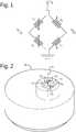
- Fig. 2shows schematically perspective view of a model of a pressure sensor to elucidate the method of manufacturing a strain gage based pressure sensor according to the present application. More particular to elucidate the method to determine the positions of the four strain gages on the strain sensing side of a membrane part of the pressure port.
- Fig. 3shows schematically a cross sectional view of the model in figure 2 and
- Fig. 4shows schematically a top view of the model in figure 2 .
- the pressure sensorcomprises a port element 10.
- the port elementcomprises a fluid pressure sensitive part with a circular membrane 12 and a sealing structure 14. Via pressure port 13 fluid pressure in the device exerts pressure force on the fluid pressure side of the membrane. Opposite to the fluid pressure side the circular membrane comprises a strain sensing side.
- the strain gagesare attached to the port element in a commonly known way, for example as disclosed in US7412892B1 .
- the sealing structure 14provides a seal when the port element 10 is attached in an opening of the device.
- the circular membrane 12has a membrane central axis 30 and the port element has a port central axis 20.
- the sealing structure 14is concentric and has a sealing central axis that coincides with the port central axis 20.
- the membrane central axis 20does not coincide with the port central axis 20.
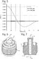
- Fig. 5shows a graph with radial strain ⁇ _r at the strain sensing side of a membrane as a function of the radius.
- Positive strainis strain with a positive value and corresponds to stretch in the surface in a particular direction resulting in tensile strain.
- Negative strainis strain with a negative value in the graph and corresponds to shrink in the surface in a particular direction resulting in compressive strain. It can be seen that the radial strain decrease with increase of the radius, i.e. the distance to the central axis 30. At a radius of about 1.2mm the radial strain is almost zero. Then with increase of radius the radial strain becomes negative, i.e. shrink in radial direction. The highest shrink is at a radius of 2mm. Then the amount of shrink decreases with increase of the radius.
- the working principle of the strain based pressure sensorsis that both strain gauges of the sensing electrical element measure radial strain but at two different radiuses.
- a characteristic of a strain gageis that the gage is sensitive for strain in a specific direction. By positioning a strain gage in such a way that the specific direction coincides a radius of the membrane, said strain gage will sense strain in radial direction and a change in resistance value of the strain gage depends substantially to a change in strain in radial direction of the membrane.
- Fig. 4which shows a top view of the circular sensing structure of Fig.2 , the radiuses are indicated with R1 and R2.
- the regions of radiuses measured by the two radial gauges of prior-art half bridge strain gagesfor example a MSG (Microfused Silicon Strain Gage) as disclosed in US 7412892B1 . It can be seen from the graph that the inner strain gage at the inner circle C2 in Fig. 4 measures positive strain (tensile strain) and the outer strain gage at the outer circle C1 measures negative strain (compressive strain) when a pressure is applied to the fluid side of the membrane.
- the two strain gaugesare used in a half bridge of a Wheatstone bridge.
- the method to determine the positions of the strain gagescomprises the following actions.
- a finite element algorithmis used to determine on the sensing side of the circular membrane by using the mathematical model of the port element to determine a first circle C1 around the membrane central axis 30 with a radius R1 and a second circle C2 around the membrane central axis 30 with a radius R2 wherein when fluid pressure is simulated to the circular membrane the degree of radial compression of the surface at the first circle C1 is equivalent to the degree of stretching of the surface at the second circle.
- the result of the second actionis providing one combination of R1 and R2 which provides the positions for the two resistors of a half Wheatstone bridge with the best sensitivity in the output signal of the half Wheatstone bridge for measuring radial strain.
- the finite element algorithmis used to determine on the first circle C1 a first position G1 and a fourth position G4 and on the second circle C2 a second position G2 and a third position G3 wherein when a parasitic force is applied to any location on the sealing structure the difference between the highest error signal and the lowest error signal measured by a simulated Wheatstone bridge comprising the four strain gages attached to the corresponding determined four positions is minimal.
- the best positions for the strain gageswill be found on the circles with radii R1 and R2 which are the least sensitive for parasitic forces acting on for instance the sealing structure of the port element.
- This featureis important as normally the total mounting force acting on the port element is globally known, but how the mounting force is distributed along the sealing structure depends on a lot of factors, for example the flatness of the sealing surface of the port element and the flatness of the opposite sealing surface of the device. Furthermore, in practice the point on the sealing structure with the highest mounting force is unknown and consequently the error at the output of the Wheatstone bridge. It might be possible that by a little increase of total mounting force by screwing the pressure sensor more tightly in the device, the point with the highest force acting on the port element changes to another position on the sealing surface.
- Fig. 6, 7 , and 8show schematically a perspective view, a cross sectional view and a top view of a concentric pressure port element with two half bridge strain gages at 180° respectively.
- the sealing structure 14is concentric and has a sealing central axis that coincides with a port central axis 20. Furthermore, the membrane central axis 30 coincides with the port central axis 20.
- Fig. 9shows a graph with the error at the output of the Wheatstone bridge as a function of the orientation/angle of a point force acting on the sealing surface 14 of the port element in figure 8 .
- the orientationis indicated by the arrows 0°, 90°, 180° and 270°.
- the graphshows that the error (Delta Vp) at the output of the half bridge G12 comprising the gages G1 and G2 of the Wheatstone bridge in Fig. 1 varies with the orientation of the point force.
- the curve of the error Delta Vphas a sinusoidal course. The highest error value is at about 80° and another top is at about 260°. The lowest error value is at about 345° and another minimum is at 170°.
- Both the two top values and the two bottom valuesdiffer; this is due to the flattened side of the upper part of the port element comprising the concentric membrane. Due to this flattened side, the port element is not fully concentric and this results in different curves for the interval 0-180° and the interval 180-360°.
- the curve of the error Delta V Nhas also a sinusoidal course.
- the highest error valueis at about 15° and another top is at about 195°.
- the lowest error valueis at about 100° and another minimum is at 280°.
- Error point force xDelta V P x ⁇ Delta V N x wherein x is the angle of the point force at the sealing surface and has a value 0 ⁇ x ⁇ 360.
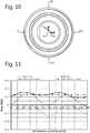
- Fig. 10shows schematically a top view of the concentric pressure port element in figure 6 with two half bridge strain gages at 90° and Fig. 11 shows a graph with the error at the output of the Wheatstone bridge as a function of the direction of a point force for the port element in figure 10 .
- the curve of Delta Vp in Fig. 11is the same as the curve of Delta Vp in Fig. 9 as the half bridge strain gage G 12 is at the same position on the port element.
- the curve of Delta V N in Fig. 11looks like a 90° shifted version of the curve of Delta V N in Fig. 9 .
- the curves of Delta V Nare not equivalent due to the flattened side of the upper part of the port element comprising the membrane. This is caused by the fact that the port element is not fully concentric.
- Figs. 12, 13 , and 14show schematically a perspective view, a cross sectional view and a top view of a non-axial symmetric pressure port element with two half bridge strain gages, respectively.
- the central axis of the membrane 12does not coincide with the central axis 20 of the port element.
- the central axis 20 of the port elementis the rotation axis of the port element when the threaded body part 11 of the port element is screwed in device.
- the central axis 20is also the central axis of the sealing structure of the port element.
- the port elementcomprises a bottomed metal tube 15 with its open side hermetically attached to the edge of a passage through the treaded body part of the port element.
- the bottomed metal tube 15could be used to position a temperature sensor in the bottomed end to sense next to the pressure in a fluid also the temperature of the fluid in the device.
- Fig. 15shows a graph with the error at the output of two half bridge gages G 12 , G 34 and the Wheatstone bridge as a function of the direction of a point force for the port element in figure 14 with half bridge gages at 180° and the half bridge gages are positioned symmetrically with respect to the plane of symmetry of the port element. It can be seen that the error Delta Vp is always negative and the error Delta V N is always positive. The absolute minimal error at the output of the Wheatstone bridge is even bigger than the absolute highest error of the curves Delta V P and Delta V N .
- Fig. 16shows schematically a top view of the non-axial symmetric pressure port element in figure 12 with two half bridge strain gages at 120°.
- Fig. 17shows a graph with the error at the output of two half bridge gages G 12 , G 34 and the Wheatstone bridge as a function of the direction of a point force for the port element in figure 14 with half bridge gages at 120° and the half bridge gages are positioned symmetrically with respect to the plane of symmetry of the port element. It can be seen that in this configuration the absolute values of Delta Vp (see figure 17 ) are smaller than the minimum absolute value of Delta Vp (see figure 15 ) for the configuration with gages at 180°. The same applies to the values of Delta V N .
- Fig. 18shows a graph with radial and tangential strain as a function of the radius.
- Fig. 18shows the curve of radial strain ⁇ _r as function of the radius as shown in Fig. 5 .
- Fig. 18shows further the curve of tangential strain ⁇ _t as a function of the radius.
- the tangential straindecreases gradually with increase of the radius but is always positive.
- the graphshows that it is possible to measure both positive tangential tensile strain and negative radial compressive strain with comparable absolute values at positions on a circle with a radius of 1,7mm.
- the examples given above to elucidate the method of the present applicationcomprise a circular membrane.
- the first circle C1 with radius R1 and the second circle C2 with radius R2are contours around the centre of the membrane with equal strain sensitivity due to fluid pressure acting on the membrane.
- the strain sensitivity of the surface on the strain sensing side at the first circle C1has a value which is opposite to the strain sensitivity of the surface at the second circle C2.
- the contours with equal sensitivity for pressureare not circular but have a shape between a circle and the shape of the circumference of the membrane.
- MEMSis for instance a technology that allows producing membranes with any shape of circumference.
- contours with equal strain sensitivity around the centre of the membraneare determined and subsequently the first contour and the second contour such that the sensitivity at the output of the Wheatstone bridge for fluid pressure is optimal.
- a constraint to find the first and second contourcould be the distance between the centre of the measuring surface of the first strain gage and the centre of the measuring surface of the second strain gage of a half bridge strain gage.
- the first and second contourare used in the second finite element action to determine the positions for the strain gages on the two contours which are the least sensitive for any known parasitic force acting on the outside of the port element.
Landscapes
- Physics & Mathematics (AREA)
- General Physics & Mathematics (AREA)
- Engineering & Computer Science (AREA)
- Theoretical Computer Science (AREA)
- Computer Hardware Design (AREA)
- Evolutionary Computation (AREA)
- Geometry (AREA)
- General Engineering & Computer Science (AREA)
- Chemical & Material Sciences (AREA)
- Analytical Chemistry (AREA)
- Measuring Fluid Pressure (AREA)
Description
- The invention relates to a method of manufacturing a strain gage based pressure sensor for measuring a fluid pressure in a device. More particular the invention relates to method for determining the positions of strain gages on a circular membrane with a fluid sensing side and a strain sensing side. The invention further relates to a pressure sensor with strain gages attached to a circular membrane.
- Strain gage based pressure transducers are used to measure pressures, such as the pressure of fluids in a vehicle. A strain gage based pressure transducer that utilizes an integrated Wheatstone bridge exhibits a high over pressure capability, high output, low offset and linear output.
- Conventional pressure transducers typically utilize four strain gages bonded to the membrane of a metal pressure port element. The membrane has a fluid side to be exposed to the fluid pressure and a strain sensing side. As is well known in the art, the gages are positioned on the strain sensing side of the membrane in such a way that two strain gages are put into compression and two strain gages are put into tension when pressure is applied to the diaphragm.
EP2735855 discloses that it is possible to position one strain gage of a half Wheatstone bridge on a first distance from the center of the membrane with compressive strain and the other strain gage of the half Wheatstone bridge on a second distance from the center of the membrane with tensile strain to improve the accuracy of the electrical signal derived from the resistance values of the pair of strain gages.- However, after mounting the pressure sensor in a device, parasitic forces acting on the metal pressure port element introduce errors in the output signal of the sensor. Parasitic forces are forces other than fluid pressure acting on the metal pressure port and can consist of for instance mounting forces, thermal-mismatch forces and package forces. The error depends on the magnitude of the parasitic force and the position and orientation of force acting on the metal pressure port. The metal pressure port element comprises a sealing surface to provide a hermetic seal between the sensor and the device. The parasitic force could be in the form of a uniform force, point force or a combination of uniform force and point force acting on the sealing surface or other location of the port. The error in the output signal of the sensor due to parasitic forces could be significant.
US6568275B1 discloses a strain gauge based sensor having a diaphragm frame with an active diaphragm portion having a high t/D ratio and an annular groove provide in at least a portion of a periphery of the diaphragm which groove increases the linearity of the output of strain gauges affixed to the top of the diaphragm and mounting stress in low pressure sensors.US6351998B1 discloses a method for designing load cells of articles, such as for example vehicle components. In a finite element analysis, a finite element model of the article is then loaded with the same loads the article will see in practice. The result is a list of element combinations in decreasing sensitivity within a user specified cross-talk tolerance.US2002100948A1 discloses a bridge circuit that includes four gage resistors which are arranged on a diaphragm. A finite element method or the like is used to obtain stress contour lines on the diaphragm.- It is an object of the present invention to provide a method of manufacturing a strain gage based pressure sensor for measuring a fluid pressure in a device with decreased sensitivity in the output signal due to forces acting on the membrane other than the fluid pressure.
- According to a first aspect of the invention, this object is achieved by a method of manufacturing a pressure sensor for measuring a fluid pressure in a device having the features of
claim 1. Advantageous embodiments and further ways of carrying out the invention may be attained by the measures mentioned in the dependent claims. - A method of manufacturing a pressure sensor for measuring a fluid pressure in a device according to the invention comprises:
- providing a port element, the port element comprises a sealing structure and a membrane with a fluid side to be exposed to the fluid pressure and, a strain sensing side and a central axis, the sealing structure providing a seal when the port element is attached in an opening of the device, the membrane having a membrane central axis and the port element having a port central axis,
- positioning four strain gages to the strain sensing side in such a way that two strain gages are put in compressive strain and two strain gages are put into tensile strain when fluid pressure is applied to the circular membrane; and,
- connecting the four strain gages to form a Wheatstone bridge circuit.
- The method is further characterized in that the method further comprises a position determining action comprising the steps:
- generating a mathematical model of the port element;
- a first finite element action determining on the sensing side of the circular membrane with a finite element algorithm using the mathematical model a first circle with a first radius or contour with equal first strain sensitivity for pressure around the membrane central axis and a second circle with a second radius or contour with equal second strain sensitivity (with opposite sign) for pressure around the membrane central axis, wherein when fluid pressure simulation is applied to the membrane the degree of compression of the surface on the first circle or contour is equivalent to the degree of stretching of the surface on the second circle or contour; and,
- a second finite element action determining with a finite element algorithm using the mathematical model on the first circle or contour a first position for a first strain gage of the four strain gages and a fourth position for a fourth strain gage of the four strain gages and on the second circle or contour a second position for a second strain gage of the four strain gages and a third position for a third strain gage of the four strain gages, wherein when a characteristic parasitic force is applied to any location on the sealing structure or any other location of the port element the difference between the highest error signal and the lowest error signal measured by the a simulated Wheatstone bridge comprising the four strain gages attached to the corresponding determined four positions is minimal.
- When attaching the four strain gages on the strain sensing side of the membrane two of the four strain gages are positioned on the first and fourth position on the first circle or contour and the other two strain gages are positioned on the second and third position on the second circle or contour.
EP2735855 teaches that the position of the strain gages put in compressive strain have a first distance R1 from the center of a concentric membrane and the position of the strain gages put in tensile strain have a second distance R2 from the center of the concentric membrane. Accordingly, the positions of the two strain gages put in compressive strain can be anywhere on a circle with radius R1 and the two strain gages put in tensile strain can be anywhere on a circle with a radius R2. This is due to the circular symmetric dimensions of the membrane. That is why in literature configurations can be found where the two configurations of two strain gages forming a half-bridge are positioned at 180° and 90° as disclosed inUS7412892 . The invention is based on the effect that when applying a parasitic force at the circumference of the port element the error introduced in the output signal of the full Wheatstone bridge formed by the four strain gages depends on the location where parasitic forces are applied on the port element and where the strain gages are positioned on the membrane and what the strain sensitive direction of the respective strain gages on the membrane is. Each half bridge gages combination has its own parasitic force error characteristic curves. It has been found that by selecting the proper rotation angle between the two half bridge gages around the centre of the membrane given a predefined parasitic force, the variation between the maximum error and minimum error due to the parasitic force in the output signal of the full Wheatstone bridge could be minimized for pressure sensors. Furthermore, in case of discrete rotational symmetric port element of the 6th order pressure port element, known as a hexagonal port plug, the present method could also be used to find the positions for the four strain gages on the membrane with the least variation in the error due to any parasitic force acting on the outside of the port element and a good sensitivity for measuring pressure of the fluid. For concentric or circular membranes the contour on the sensing side with equal strain given a fluid force acting on the membrane is a circle. Pressure sensors manufactured by for instance MEMS technology could have a membrane with a non-circular circumference. In case of a membrane with a non-circular circumference the contour has a shape between the shape of the membrane circumference and a circle.- In an embodiment, the first finite element action uses the degree of radial compressive strain on the sensing side to determine the first contour and the degree of radial tensile strain on the sensing side to determine the second contour. In an alternative embodiment, the first finite element action uses the degree of radial compressive strain on the sensing side to determine the first contour and the degree of tangential tensile strain on the sensing side to determine the second contour. These features allows to find a first and second contour for positioning the gages which provides the best sensitivity for fluid pressure acting on the membrane. The contour is then used as a starting point to find the combination positions for the strain gages on the contours which are the least sensitive for parasitic forces acting on the port element.
- In an embodiment, the second finite element action further determines with the finite element algorithm the first to fourth position of the four strain gages by simulating a uniform force acting on the sealing structure and the highest error signal measured by the simulated Wheatstone bridge is minimal. This feature enables to reduce the influence of unpredictable mounting forces in the output signal of the pressure sensor further.
- Other features and advantages will become apparent from the following detailed description, taken in conjunction with the accompanying drawings which illustrate, by way of example, various features of embodiments.
- These and other aspects, properties and advantages will be explained hereinafter based on the following description with reference to the drawings, wherein like reference numerals denote like or comparable parts, and in which:
Fig. 1 shows schematically a full Wheatstone bridge for a strain gage based pressure sensor;Fig. 2 shows schematically perspective view of a model of a pressure sensor;Fig. 3 shows schematically a cross sectional view of the model infigure 2 ;Fig. 4 shows schematically a top view of the model infigure 2 ;Fig. 5 shows a graph with radial strain at the strain sensing side of a membrane as a function of the radius;Fig. 6, 7 , and8 show schematically a perspective view, a cross sectional view and a top view of a concentric pressure port element with two half bridge strain gages at 180° respectively;Fig. 9 shows a graph with the error at the output of the Wheatstone bridge as a function of the direction of a point force for the port element infigure 8 ;Fig. 10 shows schematically a top view of the concentric pressure port element infigure 6 with two half bridge strain gages at 90°;Fig. 11 shows a graph with the error at the output of the Wheatstone bridge as a function of the direction of a point force for the port element infigure 10 ;Fig. 12, 13 , and14 show schematically a perspective view, a cross sectional view and a top view of a non-axial symmetric pressure port element with two half bridge strain gages, respectively;Fig. 15 shows a graph with the error at the output of the Wheatstone bridge as a function of the direction of a point force for the port element infigure 14 with half bridge gages at 180°;Fig. 16 shows schematically a top view of the non-axial symmetric pressure port element infigure 12 with two half bridge strain gages at 120°;Fig. 17 shows a graph with the error at the output of the Wheatstone bridge as a function of the direction of a point force for the port element infigure 16 ; andFig. 18 shows a graph with radial and tangential strain as a function of the radius.- As is understood by one of ordinary skill in the art, a strain gage based pressure sensor comprises a port element and four strain gages attached to a fluid pressure sensitive part of the port element. The four strain gages are electrically connected to form a Wheatstone bridge. The four strain gages have a position on a strain sensing side such that two strain gages are put in compressive strain and two strain gages are put in tensile strain when fluid pressure is applied to a fluid pressure side of the fluid pressure sensitive part of the port element.
Fig. 1 shows schematically a Wheatstone bridge circuit diagram for a strain gage based pressure sensor. The Wheatstone bridge is the electrical equivalent of two parallel voltage divider circuits. R1 and R2 compose one voltage divider circuit, and R4 and R3 compose the second voltage divider circuit. The output of a Wheatstone bridge is measured between the middle nodes of the two voltage dividers.- Physical phenomena, such as a change in strain applied to a specimen or a temperature shift, changes the resistance of the sensing elements in the Wheatstone bridge. The Wheatstone bridge configuration is used to help measure the small variations in resistance that the sensing elements produce corresponding to a physical change in the specimen.
- When a fluid pressure is applied gages G2 and G3 are put in tensile strain and gages G1 and G4 are put in compressive strain. An increase of compressive strain results in decrease of the resistance value of a strain gage and an increase of tensile strain results in increase of the resistance value of a strain gage. Strain gages G1 and G2 form a half bridge of the Wheatstone bridge and strain gages G3 and G4 form the other half bridge. The series connection of G1 and G2 and the series connection G3 and G4 are coupled at one side to voltage VB and at the other side to ground. The two strain gages forming a half bridge could be in the form of individual strain gages attached to the port element. In another embodiment, the two strain gages are combined to form one strain sensing element, also known as half bridge strain gage. When the fluid pressure increase, the voltage at the middle node Vp increases and the voltage at the middle node VN decreases and consequently the voltage between Vp and VN increases.
Fig. 2 shows schematically perspective view of a model of a pressure sensor to elucidate the method of manufacturing a strain gage based pressure sensor according to the present application. More particular to elucidate the method to determine the positions of the four strain gages on the strain sensing side of a membrane part of the pressure port.Fig. 3 shows schematically a cross sectional view of the model infigure 2 andFig. 4 shows schematically a top view of the model infigure 2 .- The pressure sensor comprises a
port element 10. The port element comprises a fluid pressure sensitive part with acircular membrane 12 and a sealingstructure 14. Viapressure port 13 fluid pressure in the device exerts pressure force on the fluid pressure side of the membrane. Opposite to the fluid pressure side the circular membrane comprises a strain sensing side. The strain gages are attached to the port element in a commonly known way, for example as disclosed inUS7412892B1 . - The sealing
structure 14 provides a seal when theport element 10 is attached in an opening of the device. Thecircular membrane 12 has a membranecentral axis 30 and the port element has a portcentral axis 20. The sealingstructure 14 is concentric and has a sealing central axis that coincides with the portcentral axis 20. The membranecentral axis 20 does not coincide with the portcentral axis 20. - When fluid pressure is applied to the fluid pressure side of the membrane, the surfaces below gages G1 and G4 on circle C1 with radius R1 are put in radial direction in compressive strain and the surfaces below gages G2 and G3 on circle C2 with radius R2 are put in radial direction in tensile strain. This will be elucidated by means of
fig 5 . Fig. 5 shows a graph with radial strain ε_r at the strain sensing side of a membrane as a function of the radius. Positive strain is strain with a positive value and corresponds to stretch in the surface in a particular direction resulting in tensile strain. Negative strain is strain with a negative value in the graph and corresponds to shrink in the surface in a particular direction resulting in compressive strain. It can be seen that the radial strain decrease with increase of the radius, i.e. the distance to thecentral axis 30. At a radius of about 1.2mm the radial strain is almost zero. Then with increase of radius the radial strain becomes negative, i.e. shrink in radial direction. The highest shrink is at a radius of 2mm. Then the amount of shrink decreases with increase of the radius.- The working principle of the strain based pressure sensors is that both strain gauges of the sensing electrical element measure radial strain but at two different radiuses. A characteristic of a strain gage is that the gage is sensitive for strain in a specific direction. By positioning a strain gage in such a way that the specific direction coincides a radius of the membrane, said strain gage will sense strain in radial direction and a change in resistance value of the strain gage depends substantially to a change in strain in radial direction of the membrane. In
Fig. 4 , which shows a top view of the circular sensing structure ofFig.2 , the radiuses are indicated with R1 and R2. InFig. 5 are indicated the regions of radiuses measured by the two radial gauges of prior-art half bridge strain gages, for example a MSG (Microfused Silicon Strain Gage) as disclosed inUS 7412892B1 . It can be seen from the graph that the inner strain gage at the inner circle C2 inFig. 4 measures positive strain (tensile strain) and the outer strain gage at the outer circle C1 measures negative strain (compressive strain) when a pressure is applied to the fluid side of the membrane. The two strain gauges are used in a half bridge of a Wheatstone bridge. - The method to determine the positions of the strain gages comprises the following actions.
- First a mathematical model of the port element for use in a finite element algorithm is generated in a way known to the person skilled in the art. In a second action, a finite element algorithm is used to determine on the sensing side of the circular membrane by using the mathematical model of the port element to determine a first circle C1 around the membrane
central axis 30 with a radius R1 and a second circle C2 around the membranecentral axis 30 with a radius R2 wherein when fluid pressure is simulated to the circular membrane the degree of radial compression of the surface at the first circle C1 is equivalent to the degree of stretching of the surface at the second circle. The result of the second action is providing one combination of R1 and R2 which provides the positions for the two resistors of a half Wheatstone bridge with the best sensitivity in the output signal of the half Wheatstone bridge for measuring radial strain. - Subsequently, the finite element algorithm is used to determine on the first circle C1 a first position G1 and a fourth position G4 and on the second circle C2 a second position G2 and a third position G3 wherein when a parasitic force is applied to any location on the sealing structure the difference between the highest error signal and the lowest error signal measured by a simulated Wheatstone bridge comprising the four strain gages attached to the corresponding determined four positions is minimal. By this second finite element action, the best positions for the strain gages will be found on the circles with radii R1 and R2 which are the least sensitive for parasitic forces acting on for instance the sealing structure of the port element. This feature is important as normally the total mounting force acting on the port element is globally known, but how the mounting force is distributed along the sealing structure depends on a lot of factors, for example the flatness of the sealing surface of the port element and the flatness of the opposite sealing surface of the device. Furthermore, in practice the point on the sealing structure with the highest mounting force is unknown and consequently the error at the output of the Wheatstone bridge. It might be possible that by a little increase of total mounting force by screwing the pressure sensor more tightly in the device, the point with the highest force acting on the port element changes to another position on the sealing surface. The effect that the error in the output signal of the Wheatstone bridge due to a specified parasitic force varies along the sealing surface, gave us the insight that other angular positions of the half bridge strain gages might result is pressure sensors which are less sensitive for nonuniform mounting forces. This will be elucidated by two examples here below.
Fig. 6, 7 , and8 show schematically a perspective view, a cross sectional view and a top view of a concentric pressure port element with two half bridge strain gages at 180° respectively. The sealingstructure 14 is concentric and has a sealing central axis that coincides with a portcentral axis 20. Furthermore, the membranecentral axis 30 coincides with the portcentral axis 20.Fig. 9 shows a graph with the error at the output of the Wheatstone bridge as a function of the orientation/angle of a point force acting on the sealingsurface 14 of the port element infigure 8 . InFig. 8 the orientation is indicated by thearrows 0°, 90°, 180° and 270°. The graph shows that the error (Delta Vp) at the output of the half bridge G12 comprising the gages G1 and G2 of the Wheatstone bridge inFig. 1 varies with the orientation of the point force. The curve of the error Delta Vp has a sinusoidal course. The highest error value is at about 80° and another top is at about 260°. The lowest error value is at about 345° and another minimum is at 170°. Both the two top values and the two bottom values differ; this is due to the flattened side of the upper part of the port element comprising the concentric membrane. Due to this flattened side, the port element is not fully concentric and this results in different curves for the interval 0-180° and the interval 180-360°.- The curve of the error Delta VN has also a sinusoidal course. The highest error value is at about 15° and another top is at about 195°. The lowest error value is at about 100° and another minimum is at 280°.
- The error at the output of the Wheatstone bridge corresponds to the solid line with squared markers and the name "Error point force". This error can be obtained by the equation:

value 0≤x<360. - Furthermore, in the graph of
Fig. 9 the curve of the error due to a Uniform force is shown. This error is orientation independent and is a line with a constant value. Fig. 10 shows schematically a top view of the concentric pressure port element infigure 6 with two half bridge strain gages at 90° andFig. 11 shows a graph with the error at the output of the Wheatstone bridge as a function of the direction of a point force for the port element infigure 10 . The curve of Delta Vp inFig. 11 is the same as the curve of Delta Vp inFig. 9 as the half bridge strain gage G12 is at the same position on the port element. The curve of Delta VN inFig. 11 looks like a 90° shifted version of the curve of Delta VN inFig. 9 . The curves of Delta VN are not equivalent due to the flattened side of the upper part of the port element comprising the membrane. This is caused by the fact that the port element is not fully concentric.- When comparing the curves in
Fig. 9 andFig. 11 , it can be seen that the difference between the maximum error and minimum error in the output signal of the Wheatstone bridge (Error point force) inFig. 11 is smaller than the difference between the maximum error and minimum error in the output signal of the Wheatstone bridge (Error point force) inFig. 9 . For this specific example the difference is improved with a factor of around 4. This means that a configuration with half bridge strain gages at 90° is less sensitive for the imperfections of the sealing surfaces than a configuration with half bridge strain gages at 180°. Further, by comparing the value of the Error caused by a uniform force acting on the sealing structure, it can be seen that the value of the error at the output of the Wheatstone bridge is almost the same. The difference is caused by the flattened side of the port element making it not fully concentric. Figs. 12, 13 , and14 show schematically a perspective view, a cross sectional view and a top view of a non-axial symmetric pressure port element with two half bridge strain gages, respectively. In this embodiment, the central axis of themembrane 12 does not coincide with thecentral axis 20 of the port element. Thecentral axis 20 of the port element is the rotation axis of the port element when the threadedbody part 11 of the port element is screwed in device. Thecentral axis 20 is also the central axis of the sealing structure of the port element. In this embodiment, the port element comprises a bottomedmetal tube 15 with its open side hermetically attached to the edge of a passage through the treaded body part of the port element. The bottomedmetal tube 15 could be used to position a temperature sensor in the bottomed end to sense next to the pressure in a fluid also the temperature of the fluid in the device.Fig. 15 shows a graph with the error at the output of two half bridge gages G12, G34 and the Wheatstone bridge as a function of the direction of a point force for the port element infigure 14 with half bridge gages at 180° and the half bridge gages are positioned symmetrically with respect to the plane of symmetry of the port element. It can be seen that the error Delta Vp is always negative and the error Delta VN is always positive. The absolute minimal error at the output of the Wheatstone bridge is even bigger than the absolute highest error of the curves Delta VP and Delta VN.Fig. 16 shows schematically a top view of the non-axial symmetric pressure port element infigure 12 with two half bridge strain gages at 120°.Fig. 17 shows a graph with the error at the output of two half bridge gages G12, G34 and the Wheatstone bridge as a function of the direction of a point force for the port element infigure 14 with half bridge gages at 120° and the half bridge gages are positioned symmetrically with respect to the plane of symmetry of the port element. It can be seen that in this configuration the absolute values of Delta Vp (seefigure 17 ) are smaller than the minimum absolute value of Delta Vp (seefigure 15 ) for the configuration with gages at 180°. The same applies to the values of Delta VN. The difference between the maximum value and minimum value of the error at the output of the Wheatstone bridge, curve Error point force, is about 0.04%FS (seefigure 17 ) whereas for the 180° configuration the difference is 0.25%FS. FS means full scale. So by changing the angle between the two half bridge gages from 180° to 120° the sensitivity to point forces is reduced significantly (factor 6). It further reduced the sensitivity for uniform forces acting on the sealing structure from -0.432%FS to 0.007%FS (factor 62).- The examples given above demonstrate that by using the second finite element action which calculates for different positions of the first gage G1 and fourth gage G4 both measuring radial strain on the first circle C1 and different positions of the second gage G2 and the third gage G3 both measuring radial strain on the second circle C2 the corresponding curve of the error at the output of the Wheatstone bridge, it is possible to reduce the sensitivity of the pressure sensor for parasitic forces by attaching the four strain gages at the determined corresponding four positions.
- However, it is also possible to use this method to determine better radial positions for the half bridge gages wherein one of the two strain gages of a half bridge gage measures radial strain and the other measures tangential strain. Tangential strain is strain in a direction perpendicular to a radius of the concentric membrane.
Fig. 18 shows a graph with radial and tangential strain as a function of the radius.Fig. 18 shows the curve of radial strain ε_r as function of the radius as shown inFig. 5 .Fig. 18 shows further the curve of tangential strain ε_t as a function of the radius. The tangential strain decreases gradually with increase of the radius but is always positive. The graph shows that it is possible to measure both positive tangential tensile strain and negative radial compressive strain with comparable absolute values at positions on a circle with a radius of 1,7mm. - The examples given above only take into account the mounting forces acting on the sealing surface to determine the positions on the first and second circle. Next to the mounting forces other parasitic forces could be taken into account. For example a part of the pressure sensor could be welded, pressed or crimped to the port element. This results in characteristic stress (= strain) in the membrane which differs over the manufactured products. This characteristic stress could be modelled as characteristic point forces acting on specific surfaces or locations of the port element. When also the magnitude of the different sources of parasitic forces is modelled, the positions on the first and second circle could be determined which are the least sensitive for the combination of all these parasitic force variations.
- The examples given above to elucidate the method of the present application comprise a circular membrane. The first circle C1 with radius R1 and the second circle C2 with radius R2 are contours around the centre of the membrane with equal strain sensitivity due to fluid pressure acting on the membrane. The strain sensitivity of the surface on the strain sensing side at the first circle C1 has a value which is opposite to the strain sensitivity of the surface at the second circle C2. However, when the membrane has a non-circular circumference, for example a squared, rectangular of elliptical, the contours with equal sensitivity for pressure are not circular but have a shape between a circle and the shape of the circumference of the membrane. MEMS is for instance a technology that allows producing membranes with any shape of circumference. In that case, with the first finite element action, contours with equal strain sensitivity around the centre of the membrane are determined and subsequently the first contour and the second contour such that the sensitivity at the output of the Wheatstone bridge for fluid pressure is optimal. A constraint to find the first and second contour could be the distance between the centre of the measuring surface of the first strain gage and the centre of the measuring surface of the second strain gage of a half bridge strain gage. The first and second contour are used in the second finite element action to determine the positions for the strain gages on the two contours which are the least sensitive for any known parasitic force acting on the outside of the port element. By means of this method batches of fluid pressure sensors are manufactured which have the least spread in variation of the output signal of the pressure sensor due to mounting forces and/or stress in the port element due to attaching components of pressure sensor to the port element.
- While the invention has been described in terms of several embodiments, it is contemplated that alternatives, modifications, permutations and equivalents thereof will become apparent to those skilled in the art upon reading the specification and upon study of the drawings. The invention is not limited to the illustrated embodiments. Changes can be made without departing from the scope of the appended claims.

Claims (13)
- Method of manufacturing a pressure sensor for measuring a fluid pressure in a device, the method comprising:- providing a port element (10), the port element comprising a sealing structure (14) and a membrane (12) with a fluid side to be exposed to the fluid pressure and a strain sensing side, the sealing structure providing a seal when the port element is attached in an opening of the device, the membrane having a membrane central axis (30) and the port element having a port central axis (20),- positioning four strain gages (G1...G4) to the strain sensing side in such a way that two strain gages (G1, G4) are put in compressive strain and two strain gages (G2, G3) are put into tensile strain when fluid pressure is applied to the membrane; and,- connecting the four strain gages to form a Wheatstone bridge circuit;characterized in that,
the method further comprises a strain gage position determining action comprising:- generating a mathematical model of the port element;- a first finite element action determining on the sensing side of the membrane with a finite element algorithm using the mathematical model a first contour (C1) around the membrane central axis with equal first strain sensitivity for pressure along the first contour line and a second contour (C2) around the membrane central axis with equal second strain sensitivity for pressure along the second contour line wherein when fluid pressure is applied to the membrane the degree of compression of the surface on the first contour is equivalent to the degree of stretching of the surface on the second contour; and,- a second finite element action determining with a finite element algorithm using the mathematical model on the first contour a first position for a first strain gage (G1) of the four strain gages and a fourth position for a fourth strain gage (G4) of the four strain gages and on the second contour a second position for a second strain gage (G2) of the four strain gages and a third position for a third strain gage (G3) of the four strain gages, the four determined positions defining the positions of four strain gauges of a simulated Wheatstone bridge, wherein when a characteristic parasitic force applied to any location on the sealing structure or any other location of the port element generates an error signal, for the four determined positions it holds that the difference between the maximum error signal and the minimum error signal measured by the simulated Wheatstone bridge in response to the characteristic parasitic force applied to any location on the sealing structure or any other location of the port element is minimal; and the method further comprises:- positioning two of the four strain gages on the two positions on the first contour (C1) and two of the four strain gages on the two positions on the second contour (C2). - The method according to claim 1, wherein the first finite element action uses the degree of radial compressive strain on the sensing side to determine the first contour and the degree of radial tensile strain on the sensing side to determine the second contour.
- The method according to claim 1, wherein the first finite element action uses the degree of radial compressive strain on the sensing side to determine the first contour and the degree of tangential tensile strain on the sensing side to determine the second contour.
- The method according to any of the claims 1 - 3, wherein the membrane is a circular membrane.
- The method according to claim 4, wherein the first position and the second position are on a first radial line and the third position and the fourth position are on a second radial line.
- The method according to any of the claims 1 - 5, wherein the port element is non-axially symmetric.
- The method according to any of the claims 4-5, wherein the sealing structure has a sealing central axis that does not coincide with the membrane central axis of the circular membrane.
- The method according to any of the claims 1 - 7, wherein the second finite element action further determines with the finite element algorithm the first to fourth position of the four strain gages by simulating a uniform force acting on the sealing structure and the maximum error signal measured by the simulated Wheatstone bridge is minimal.
- The method according to any of the claims 1 - 8, wherein the sealing structure is circular.
- The method according to any of the claims 1 - 9, wherein the port element has at least one plane of symmetry.
- The method according to any of the claims 1 - 10, wherein the membrane is a circular membrane and the four strain gages are embodied as two half bridge strain sensing elements, a half bridge strain sensing element comprising two strain gages both measuring strain in a direction parallel to a line through centre points of the two strain gages; the centre points are at a defined distance from each other; the method determines in the first finite element action a first circular contour line with a radius and second circular contour line with a radius such that the difference between the radius of the first circular contour line and the radius of the second circular contour line equals the defined distance, the first position and second position have been determined in the second finite element action by using a first radial line on the first and second circle, and the third position and fourth position have been determined by using a second radial line on the first and second circle.
- The method according to any of the claims 1 - 10, wherein the membrane is a circular membrane and the four strain gages are embodied as two half bridge strain sensing elements, a half bridge strain sensing element comprising two strain gages one measuring strain in a direction parallel to a line through centre points of the two strain gages and another measuring strain in a direction perpendicular to the line through the centre points; the centre points are at a defined distance from each other; the first finite element action determines a first circular contour line with a radius and a second circular contour line with a radius such that the difference between the radius of the first circular contour line and the radius of the second circular contour line equals the defined distance, the first position and second position have been determined in the second finite element action by using a first radial line on the first and second circle, and the third position and fourth position have been determined by using a second radial line on the first and second circle.
- The method according to any of the claims 1 - 10, wherein the four strain gages are embodied as two half bridge strain sensing elements, a half bridge strain sensing element comprising two strain gages one measuring strain in a direction parallel to a line through centre points of the two strain gages and another measuring strain in a direction perpendicular to the line through the centre points; the centre points are at a defined distance from each other; the first finite element action determines a contour wherein the tensile strain in tangential direction on the contour is opposite to the compressive strain in radial direction on the contour and the second finite element action uses the contour as first and second contour to determine the positions of the four strain gages wherein the distance between the first position and the fourth position and the distance between the second position and third position is the defined distance between the centre points of the two strain gages.
Priority Applications (5)
| Application Number | Priority Date | Filing Date | Title |
|---|---|---|---|
| EP16166285.3AEP3236226B1 (en) | 2016-04-20 | 2016-04-20 | Method of manufacturing a pressure sensor |
| US15/479,332US10871413B2 (en) | 2016-04-20 | 2017-04-05 | Method of manufacturing a pressure sensor |
| JP2017082778AJP6860409B2 (en) | 2016-04-20 | 2017-04-19 | How to make a pressure sensor |
| KR1020170050471AKR102313908B1 (en) | 2016-04-20 | 2017-04-19 | Method of manufacturing a pressure sensor |
| CN201710255577.0ACN107449537B (en) | 2016-04-20 | 2017-04-19 | Method for manufacturing pressure sensor |
Applications Claiming Priority (1)
| Application Number | Priority Date | Filing Date | Title |
|---|---|---|---|
| EP16166285.3AEP3236226B1 (en) | 2016-04-20 | 2016-04-20 | Method of manufacturing a pressure sensor |
Publications (2)
| Publication Number | Publication Date |
|---|---|
| EP3236226A1 EP3236226A1 (en) | 2017-10-25 |
| EP3236226B1true EP3236226B1 (en) | 2019-07-24 |
Family
ID=55802274
Family Applications (1)
| Application Number | Title | Priority Date | Filing Date |
|---|---|---|---|
| EP16166285.3AActiveEP3236226B1 (en) | 2016-04-20 | 2016-04-20 | Method of manufacturing a pressure sensor |
Country Status (5)
| Country | Link |
|---|---|
| US (1) | US10871413B2 (en) |
| EP (1) | EP3236226B1 (en) |
| JP (1) | JP6860409B2 (en) |
| KR (1) | KR102313908B1 (en) |
| CN (1) | CN107449537B (en) |
Cited By (1)
| Publication number | Priority date | Publication date | Assignee | Title |
|---|---|---|---|---|
| EP4528243A1 (en)* | 2023-09-25 | 2025-03-26 | Illinois Tool Works Inc. | Differential pressure sensors for dynamic, high pressure, hydraulic systems |
Families Citing this family (14)
| Publication number | Priority date | Publication date | Assignee | Title |
|---|---|---|---|---|
| US8496647B2 (en) | 2007-12-18 | 2013-07-30 | Intuitive Surgical Operations, Inc. | Ribbed force sensor |
| US8561473B2 (en) | 2007-12-18 | 2013-10-22 | Intuitive Surgical Operations, Inc. | Force sensor temperature compensation |
| JP6663314B2 (en)* | 2016-07-08 | 2020-03-11 | アズビル株式会社 | Pressure sensor |
| GB2552025B (en) | 2016-07-08 | 2020-08-12 | Sovex Ltd | Boom conveyor |
| US20180180494A1 (en)* | 2016-12-22 | 2018-06-28 | Honeywell International Inc. | High Sensitivity Silicon Piezoresistor Force Sensor |
| US11460360B2 (en)* | 2017-11-14 | 2022-10-04 | Intuitive Surgical Operations, Inc. | Split bridge circuit force sensor |
| CN209326840U (en) | 2018-12-27 | 2019-08-30 | 热敏碟公司 | Pressure sensor and pressure transmitter |
| CN110991108B (en)* | 2019-11-22 | 2023-04-25 | 湖南城市学院 | Mechanical arm joint torque sensor structural design method |
| DE102019008761A1 (en) | 2019-12-14 | 2021-06-17 | PRlGNlTZ Mikrosystemtechnik GmbH | Pressure sensor with a membrane with sensor chips with measuring bridges with sensor elements |
| US11885704B2 (en) | 2020-07-27 | 2024-01-30 | Precision Biomems Corporation | Flexible two-dimensional sheet array of electronic sensor devices |
| CN113358268A (en)* | 2021-06-07 | 2021-09-07 | 中国工程物理研究院总体工程研究所 | Pressure sensor |
| US11994443B2 (en) | 2022-03-24 | 2024-05-28 | Sensata Technologies, Inc. | Sensing device with gauge |
| US20240125658A1 (en)* | 2022-10-18 | 2024-04-18 | Measurement Specialties, Inc. | Membrane of a sensor with multiple ranges |
| CN118090020B (en)* | 2024-04-26 | 2024-07-19 | 合肥智感科技有限公司 | High-reliability intelligent pressure sensor |
Family Cites Families (174)
| Publication number | Priority date | Publication date | Assignee | Title |
|---|---|---|---|---|
| US4131088A (en) | 1976-11-08 | 1978-12-26 | The Bendix Corporation | Multiple function pressure sensor |
| US4287772A (en) | 1978-05-18 | 1981-09-08 | Gulton Industries, Inc. | Strain gage transducer and process for fabricating same |
| CA1162243A (en) | 1979-12-26 | 1984-02-14 | Jonathon H. Katz | Test pin |
| US4347745A (en) | 1980-12-22 | 1982-09-07 | Bourns Instruments, Inc. | Pressure measuring apparatus |
| US4400681A (en) | 1981-02-23 | 1983-08-23 | General Motors Corporation | Semiconductor pressure sensor with slanted resistors |
| FR2520305B1 (en) | 1982-01-28 | 1985-09-06 | Aerospatiale | SUSPENSION WITH OSCILLATING ARMS FOR A TWO-WHEEL TRAIN OF A VEHICLE AND AN ELASTIC RECALL AND ANTI-ROLL COUPLING SYSTEM FOR SUCH A SUSPENSION |
| DE3532333A1 (en)* | 1985-09-11 | 1987-03-19 | Degussa | ELECTRICAL PROBE FOR PRESSURE AND FORCE MEASUREMENTS |
| US4771427A (en) | 1986-10-02 | 1988-09-13 | United Technologies Corporation | Equalization in redundant channels |
| US4825876A (en) | 1988-02-23 | 1989-05-02 | Abbott Laboratories | Encapsulated blood pressure transducer |
| EP0381775B1 (en) | 1988-07-26 | 1994-11-23 | Hitachi Construction Machinery Co., Ltd. | Pressure sensor |
| US4888662A (en) | 1988-12-08 | 1989-12-19 | Texas Instruments Incorporated | High pressure package for pressure transducers |
| US4903164A (en) | 1988-12-08 | 1990-02-20 | Texas Instruments Incorporated | O-ring/back-up ring seal for high pressure transducers |
| US5184515A (en)* | 1989-06-22 | 1993-02-09 | Ic Sensors, Inc. | Single diaphragm transducer with multiple sensing elements |
| US5181417A (en) | 1989-07-10 | 1993-01-26 | Nippon Soken, Inc. | Pressure detecting device |
| US5060108A (en) | 1990-01-25 | 1991-10-22 | Texas Instruments Incorporated | Packaging and sealing for pressure transducer |
| JPH03293534A (en) | 1990-04-12 | 1991-12-25 | Nissan Motor Co Ltd | Pressure sensor mounting equipment |
| US5173766A (en) | 1990-06-25 | 1992-12-22 | Lsi Logic Corporation | Semiconductor device package and method of making such a package |
| JPH0465643A (en) | 1990-07-05 | 1992-03-02 | Mitsubishi Electric Corp | Semiconductor pressure sensor and its manufacturing method |
| DE4023420A1 (en) | 1990-07-24 | 1992-01-30 | Pfister Gmbh | PRESSURE SENSOR |
| KR950005891B1 (en) | 1990-11-28 | 1995-06-02 | 미쓰비시덴키 가부시키가이샤 | Pressure sensor |
| US5184107A (en) | 1991-01-28 | 1993-02-02 | Honeywell, Inc. | Piezoresistive pressure transducer with a conductive elastomeric seal |
| US5231301A (en) | 1991-10-02 | 1993-07-27 | Lucas Novasensor | Semiconductor sensor with piezoresistors and improved electrostatic structures |
| CA2062543C (en) | 1992-03-09 | 1996-09-17 | Douglas Milne | Cable bolt monitoring device |
| JPH0637334A (en) | 1992-07-16 | 1994-02-10 | Copal Electron Co Ltd | Structure of pressure sensor |
| US5331857A (en) | 1992-08-21 | 1994-07-26 | General Automotive Specialty Co., Inc. | Pressure transducer |
| US5425371A (en) | 1992-10-05 | 1995-06-20 | Metatech Corporation | Fiberoptic pressure transducer |
| DE4234289C1 (en) | 1992-10-12 | 1993-11-25 | Fibronix Sensoren Gmbh | Pressure sensor e.g. for use in corrosive media - has non-metallic sensor element fitted in chemically resistant polymeric housing contg. expansion preventing tube |
| DE4407212C1 (en) | 1992-10-12 | 1995-08-03 | Fibronix Sensoren Gmbh | Pressure sensor |
| JPH06160221A (en)* | 1992-11-20 | 1994-06-07 | Tokai Rika Co Ltd | Wiring pattern of strain sensor |
| US5349865A (en) | 1993-08-30 | 1994-09-27 | Kavlico Corporation | Wide-pressure-range, adaptable, simplified pressure transducer |
| US5457988A (en) | 1993-10-28 | 1995-10-17 | Panex Corporation | Side pocket mandrel pressure measuring system |
| US5448444A (en) | 1994-01-28 | 1995-09-05 | United Technologies Corporation | Capacitive pressure sensor having a reduced area dielectric spacer |
| JPH0821775A (en) | 1994-07-08 | 1996-01-23 | Fuji Koki Seisakusho:Kk | Pressure sensor |
| JPH08178778A (en) | 1994-12-27 | 1996-07-12 | Mitsubishi Electric Corp | Semiconductor pressure detector |
| DE59504814D1 (en) | 1995-03-31 | 1999-02-25 | Endress Hauser Gmbh Co | Pressure sensor |
| CA2217019A1 (en) | 1995-04-28 | 1996-10-31 | Rosemount Inc. | Pressure transmitter with high pressure isolator mounting assembly |
| DE19521832A1 (en) | 1995-06-16 | 1996-12-19 | Bosch Gmbh Robert | Pressure measuring device |
| US5869766A (en) | 1995-10-03 | 1999-02-09 | Nt International, Inc. | Non-contaminating pressure transducer module |
| USRE38557E1 (en) | 1995-10-03 | 2004-07-20 | Nt International, Inc. | Non-contaminating pressure transducer module |
| DE19547890A1 (en) | 1995-12-21 | 1997-06-26 | Bosch Gmbh Robert | Sealing unit for a fuel pressure sensor |
| US5802912A (en) | 1996-01-25 | 1998-09-08 | Delco Electronics Corporation | Electrical terminal apparatus |
| US5629486A (en) | 1996-01-25 | 1997-05-13 | Delco Electronics Corporation | Pressure sensor apparatus with integrated circuit mounted thereon |
| US6033544A (en) | 1996-10-11 | 2000-03-07 | Sarnoff Corporation | Liquid distribution system |
| US5741975A (en) | 1996-07-31 | 1998-04-21 | Motorola, Inc. | Media isolated differential pressure sensor and fluid injection method |
| US6700174B1 (en) | 1997-09-25 | 2004-03-02 | Integrated Micromachines, Inc. | Batch fabricated semiconductor thin-film pressure sensor and method of making same |
| JP4161410B2 (en) | 1997-07-25 | 2008-10-08 | 株式会社デンソー | Pressure detection device |
| US20040099061A1 (en) | 1997-12-22 | 2004-05-27 | Mks Instruments | Pressure sensor for detecting small pressure differences and low pressures |
| DE19811970C2 (en) | 1998-03-19 | 2000-05-18 | Klaus Kobold | Measuring display device |
| US6204594B1 (en) | 1998-06-12 | 2001-03-20 | Cooper Automotive Products, Inc. | Spark plug with pressure sensor |
| JP3309808B2 (en) | 1998-08-04 | 2002-07-29 | 株式会社デンソー | Pressure detector |
| US6006607A (en) | 1998-08-31 | 1999-12-28 | Maxim Integrated Products, Inc. | Piezoresistive pressure sensor with sculpted diaphragm |
| FR2791430B1 (en) | 1999-03-25 | 2001-09-21 | Denso Corp | PRESSURE SENSOR WITH METAL ROD ATTACHED TO A CASE THAT CAN BE SUBJECT TO A DEVICE DIRECTLY, AND A METHOD FOR MANUFACTURING THE SAME |
| JP2001041838A (en) | 1999-08-03 | 2001-02-16 | Yamatake Corp | Pressure sensor and method of manufacturing the same |
| JP4281178B2 (en) | 1999-10-06 | 2009-06-17 | 株式会社デンソー | Semiconductor pressure sensor |
| JP3911930B2 (en) | 1999-10-28 | 2007-05-09 | 株式会社デンソー | Glow plug with combustion pressure sensor |
| JP4300663B2 (en) | 1999-12-24 | 2009-07-22 | 株式会社デンソー | Combustion pressure sensor structure |
| US6453747B1 (en) | 2000-01-12 | 2002-09-24 | Peter A. Weise | Hermetic pressure transducer |
| US6550337B1 (en) | 2000-01-19 | 2003-04-22 | Measurement Specialties, Inc. | Isolation technique for pressure sensing structure |
| US20020029639A1 (en) | 2000-01-19 | 2002-03-14 | Measurement Specialities, Inc. | Isolation technique for pressure sensing structure |
| DE10031120A1 (en) | 2000-06-30 | 2002-01-17 | Grieshaber Vega Kg | Diaphragm Seals |
| US6568276B1 (en)* | 2000-08-04 | 2003-05-27 | Measurement Specialties, Inc. | Strain gauge based sensor with improved linearity |
| US6434456B1 (en) | 2000-09-07 | 2002-08-13 | Kelsey-Hayes Company | High reliability pressure sensor |
| US6351998B1 (en)* | 2000-09-19 | 2002-03-05 | General Motors Corporation | Method for designing a load cell |
| US6487911B1 (en) | 2000-11-21 | 2002-12-03 | Texas Instruments Incorporated | Pressure sensor apparatus |
| US6556939B1 (en) | 2000-11-22 | 2003-04-29 | Smartsignal Corporation | Inferential signal generator for instrumented equipment and processes |
| US6505398B2 (en) | 2000-12-04 | 2003-01-14 | Kavlico Corporation | Very high pressure miniature sensing and mounting technique |
| JP4843877B2 (en)* | 2001-01-31 | 2011-12-21 | 株式会社デンソー | Semiconductor dynamic quantity sensor |
| US6536287B2 (en) | 2001-08-16 | 2003-03-25 | Honeywell International, Inc. | Simplified capacitance pressure sensor |
| US7322246B2 (en) | 2002-03-13 | 2008-01-29 | Ip Development, Llc | Pressure sensor with pressure translation |
| DE10223357A1 (en) | 2002-05-25 | 2003-12-04 | Bosch Gmbh Robert | Pressure measuring device |
| US6952042B2 (en) | 2002-06-17 | 2005-10-04 | Honeywell International, Inc. | Microelectromechanical device with integrated conductive shield |
| DE10228000A1 (en) | 2002-06-22 | 2004-01-08 | Robert Bosch Gmbh | Pressure measuring device |
| US6763724B2 (en) | 2002-07-10 | 2004-07-20 | Texas Instruments Incorporated | Hermetic pressure transducer |
| US6715357B2 (en) | 2002-07-10 | 2004-04-06 | Texas Instruments Incorporated | Hermetic pressure transducer |
| US6782758B2 (en) | 2002-07-10 | 2004-08-31 | Texas Instruments Incorporated | Hermetic pressure transducer |
| US6845664B1 (en) | 2002-10-03 | 2005-01-25 | The United States Of America As Represented By The Administrator Of National Aeronautics And Space Administration | MEMS direct chip attach packaging methodologies and apparatuses for harsh environments |
| FR2849192B1 (en) | 2002-12-20 | 2005-03-04 | Siemens Vdo Automotive | APPARATUS FOR DETECTING PRESSURE IN THE COMBUSTION CHAMBER OF AN ENGINE |
| US20040132900A1 (en) | 2003-01-08 | 2004-07-08 | International Business Machines Corporation | Polyimide compositions and use thereof in ceramic product defect repair |
| US6815071B2 (en) | 2003-01-24 | 2004-11-09 | Delphi Technologies, Inc. | Glass frit bond line |
| US6846184B2 (en) | 2003-01-24 | 2005-01-25 | High Connection Density Inc. | Low inductance electrical contacts and LGA connector system |
| JP3915715B2 (en)* | 2003-03-07 | 2007-05-16 | 株式会社デンソー | Semiconductor pressure sensor |
| US7570065B2 (en) | 2006-03-01 | 2009-08-04 | Loadstar Sensors Inc | Cylindrical capacitive force sensing device and method |
| JP2005037310A (en) | 2003-07-18 | 2005-02-10 | Fuji Koki Corp | Pressure sensor |
| JP4774678B2 (en) | 2003-08-29 | 2011-09-14 | 富士電機株式会社 | Pressure sensor device |
| JP4075776B2 (en) | 2003-11-13 | 2008-04-16 | 株式会社デンソー | Physical quantity sensor and pressure sensor |
| US6945118B2 (en) | 2004-01-13 | 2005-09-20 | Honeywell International Inc. | Ceramic on metal pressure transducer |
| EP1560012B1 (en) | 2004-01-30 | 2010-06-02 | Danfoss A/S | A pressure transmitter |
| US7207214B1 (en) | 2004-02-17 | 2007-04-24 | Wlodarczyk Marek T | Glow plug integrated pressure sensor |
| DE102005009351B4 (en) | 2004-03-03 | 2013-05-23 | Denso Corporation | Pressure sensor and method for its assembly |
| US7252009B2 (en) | 2004-08-27 | 2007-08-07 | Ashcroft-Nagano, Inc. | System and method for pressure measurement |
| US7100455B2 (en) | 2004-08-27 | 2006-09-05 | Dresser-Nagano, Inc. | System and method for pressure measurement |
| US7270010B2 (en) | 2004-08-27 | 2007-09-18 | Ashcroft-Nagano, Inc. | System and method for pressure measurement |
| JP4419847B2 (en) | 2004-09-16 | 2010-02-24 | 株式会社デンソー | Pressure sensor |
| DE102004048367B4 (en) | 2004-10-01 | 2010-10-28 | Endress + Hauser Gmbh + Co. Kg | Method for filling a pressure measuring transducer |
| US7302855B2 (en) | 2004-10-28 | 2007-12-04 | Denso Corporation | Pressure detection device |
| US7032456B1 (en) | 2004-12-30 | 2006-04-25 | The United States Of America As Represented By The Secretary Of The Navy | Isostatic piezoresistive pressure transducer with temperature output |
| JP4742593B2 (en) | 2005-01-19 | 2011-08-10 | 株式会社デンソー | Manufacturing method of pressure detecting device |
| US7197937B2 (en) | 2005-01-26 | 2007-04-03 | Sensata Technologies, Inc. | Hermetic pressure sensing device |
| US7884432B2 (en) | 2005-03-22 | 2011-02-08 | Ametek, Inc. | Apparatus and methods for shielding integrated circuitry |
| JP4421511B2 (en) | 2005-05-30 | 2010-02-24 | 三菱電機株式会社 | Semiconductor pressure sensor |
| US7021147B1 (en) | 2005-07-11 | 2006-04-04 | General Electric Company | Sensor package and method |
| CN1940514A (en)* | 2005-09-30 | 2007-04-04 | 比亚迪股份有限公司 | Force-measuring sensing method |
| TWI286383B (en) | 2005-12-23 | 2007-09-01 | Delta Electronics Inc | Semiconductor piezoresistive sensor and operation method thereof |
| DE102006008351A1 (en) | 2006-02-21 | 2007-08-23 | Robert Bosch Gmbh | Pressure measuring device for arrangement in chamber of internal combustion engine, has housing and ends of sensor cage are connected to force transmission unit and fixing unit |
| DE102006008584A1 (en) | 2006-02-24 | 2007-09-06 | Atmel Germany Gmbh | Manufacturing process for integrated piezo components |
| US7475597B2 (en) | 2006-02-27 | 2009-01-13 | Auxitrol S.A. | Stress isolated pressure sensing die |
| US7726197B2 (en) | 2006-04-26 | 2010-06-01 | Honeywell International Inc. | Force sensor package and method of forming same |
| CN101467468B (en) | 2006-06-08 | 2012-09-05 | 楼氏电子亚洲有限公司 | Acoustic device and method of manufacturing same |
| JP2008039760A (en)* | 2006-07-14 | 2008-02-21 | Denso Corp | Pressure sensor |
| JP4848904B2 (en) | 2006-09-13 | 2011-12-28 | 株式会社デンソー | Pressure sensor |
| DE102006047395A1 (en) | 2006-10-06 | 2008-04-10 | Robert Bosch Gmbh | Method for producing a sensor component and sensor component |
| WO2008060060A1 (en) | 2006-11-15 | 2008-05-22 | Jung-Hoon Kim | Subminiature linear vibrator |
| JP2008151738A (en) | 2006-12-20 | 2008-07-03 | Denso Corp | Pressure sensor |
| US20080222884A1 (en) | 2007-03-14 | 2008-09-18 | Honeywell International Inc. | Packaging for chip-on-board pressure sensor |
| ES2605170T3 (en) | 2007-03-19 | 2017-03-13 | Boston Scientific Neuromodulation Corporation | Cable manufacturing procedures and apparatus with conductors and related flexible cable configurations |
| US7383737B1 (en) | 2007-03-29 | 2008-06-10 | Delphi Technologies, Inc | Capacitive pressure sensor |
| JP5008188B2 (en) | 2007-05-31 | 2012-08-22 | ミネベア株式会社 | Triaxial force sensor and triaxial force detection method |
| US7412892B1 (en) | 2007-06-06 | 2008-08-19 | Measurement Specialties, Inc. | Method of making pressure transducer and apparatus |
| DE102007031980A1 (en) | 2007-07-10 | 2009-01-15 | Robert Bosch Gmbh | Connection unit for a pressure measuring cell |
| US8056752B2 (en) | 2007-09-12 | 2011-11-15 | Carnevali Jeffrey D | Dripless lid for beverage container |
| US7862391B2 (en) | 2007-09-18 | 2011-01-04 | Delaware Capital Formation, Inc. | Spring contact assembly |
| US7647835B2 (en) | 2007-09-19 | 2010-01-19 | Honeywell International Inc. | Pressure sensor stress isolation pedestal |
| US7578194B1 (en) | 2008-02-11 | 2009-08-25 | Sensata Technologies, Inc. | Differential fluid pressure measurement apparatus |
| DE102008001509A1 (en) | 2008-04-30 | 2009-11-05 | Robert Bosch Gmbh | Pressure sensor assembly |
| US20090315734A1 (en) | 2008-06-23 | 2009-12-24 | Silverbrook Research Pty Ltd | Electronic pen with automatically retractable nib |
| EP2138820B1 (en) | 2008-06-25 | 2016-09-21 | Sensata Technologies, Inc. | A piezoresistive pressure-measuring plug for a combustion engine |
| DE102008040180A1 (en) | 2008-07-04 | 2010-01-14 | Robert Bosch Gmbh | Pre-assembly for a contact assembly of a sensor assembly |
| US8164007B2 (en) | 2008-07-16 | 2012-04-24 | Honeywell International | Conductive elastomeric seal and method of fabricating the same |
| US8024978B2 (en) | 2009-01-21 | 2011-09-27 | Honeywell International Inc. | Media isolated pressure transducer having boss comprising single metal diaphragm |
| US7775119B1 (en) | 2009-03-03 | 2010-08-17 | S3C, Inc. | Media-compatible electrically isolated pressure sensor for high temperature applications |
| US20100267291A1 (en) | 2009-04-20 | 2010-10-21 | Scott Chabineau-Lovgren | Swaging process for improved compliant contact electrical test performance |
| JP2010256187A (en) | 2009-04-24 | 2010-11-11 | Panasonic Electric Works Co Ltd | Pressure sensor |
| US7861595B2 (en) | 2009-05-11 | 2011-01-04 | Honeywell International Inc. | Pressure sensing device for harsh environments |
| US8215176B2 (en) | 2009-05-27 | 2012-07-10 | Continental Automotive Systems, Inc. | Pressure sensor for harsh media sensing and flexible packaging |
| DE102009030702A1 (en) | 2009-06-26 | 2010-12-30 | Trafag Ag | Pressure sensor measuring element as well as pressure sensor provided therewith |
| CN101968388B (en)* | 2009-07-28 | 2012-07-04 | 湖北省电力试验研究院 | Wireless stress tester of hydro-power generating unit |
| EP2312290B1 (en) | 2009-10-16 | 2019-09-25 | First Sensor Mobility GmbH | Pressure sensor and use of same in a fluid tank |
| DE202009017430U1 (en) | 2009-12-23 | 2011-05-05 | Liebherr-Werk Ehingen Gmbh | sensor |
| EP2390641B1 (en) | 2010-05-27 | 2019-06-26 | Sensata Technologies, Inc. | Pressure Sensor |
| US8156816B2 (en) | 2010-05-27 | 2012-04-17 | Sensata Technologies, Inc. | Pressure sensor |
| US8256300B2 (en) | 2010-05-27 | 2012-09-04 | Sensata Technologies, Inc. | Pressure sensor |
| US8129624B2 (en) | 2010-05-27 | 2012-03-06 | Sensata Technologies, Inc. | Pressure sensor |
| EP2592257A1 (en) | 2010-06-11 | 2013-05-15 | Toyota Jidosha Kabushiki Kaisha | Control device for internal combustion engine |
| DE102010030488A1 (en) | 2010-06-24 | 2011-12-29 | Endress + Hauser Conducta Gesellschaft für Mess- und Regeltechnik mbH + Co. KG | Method for adjusting a measuring device in process analysis technology |
| DE102010041169A1 (en) | 2010-09-22 | 2012-03-22 | Robert Bosch Gmbh | Pressure sensor, in particular for braking device |
| EP2444786B1 (en) | 2010-10-20 | 2013-07-17 | Sensata Technologies, Inc. | A pressure measuring glow plug for a combustion engine |
| DE112011104403T5 (en) | 2010-12-15 | 2013-09-19 | Panasonic Corporation | Semiconductor pressure sensor |
| CN102353487B (en)* | 2011-06-16 | 2013-07-24 | 上海理工大学 | SMD and bridge assembly method of multi-dimensional force sensor |
| DE102011078557A1 (en) | 2011-07-01 | 2013-01-03 | Endress + Hauser Gmbh + Co. Kg | Method for operating an absolute or relative pressure sensor with a capacitive transducer |
| US20130052936A1 (en) | 2011-08-31 | 2013-02-28 | John C. Jordan | Heating and cooling ventilation system |
| DE102011088044A1 (en) | 2011-12-08 | 2013-06-13 | Robert Bosch Gmbh | Pressure sensor arrangement for detecting a pressure of a fluid medium in a measuring space |
| EP2610602A3 (en) | 2011-12-29 | 2016-12-28 | Parker Hannifin Corporation | Electroactive Polymer Pressure Sensor |
| WO2013110045A1 (en) | 2012-01-20 | 2013-07-25 | Hydra Electric Company | High dielectric strength and dc insulation for pressure sensors and switches |
| US20130192379A1 (en) | 2012-01-27 | 2013-08-01 | Neil S. Petrarca | Small form factor microfused silicon strain gage (msg) pressure sensor packaging |
| CN104126107B (en) | 2012-02-09 | 2016-08-24 | 富士电机株式会社 | Physical quantity sensor and manufacturing method of physical quantity sensor |
| CN102539055B (en)* | 2012-02-13 | 2014-04-09 | 苏州文智芯微系统技术有限公司 | High-temperature-resistant anti-corrosion pressure sensor based on smart-cut silicon isolation chip |
| US8516897B1 (en) | 2012-02-21 | 2013-08-27 | Honeywell International Inc. | Pressure sensor |
| DE102012204904A1 (en) | 2012-03-27 | 2013-10-02 | Robert Bosch Gmbh | sensor unit |
| US9003897B2 (en) | 2012-05-10 | 2015-04-14 | Honeywell International Inc. | Temperature compensated force sensor |
| US9278849B2 (en) | 2012-06-15 | 2016-03-08 | The Boeing Company | Micro-sensor package and associated method of assembling the same |
| EP2730904A1 (en) | 2012-11-12 | 2014-05-14 | Sensata Technologies, Inc. | A pressure-measuring plug for a combustion engine |
| EP2730905B1 (en) | 2012-11-12 | 2019-01-02 | Sensata Technologies, Inc. | A pressure-measuring plug for a combustion engine |
| EP2735855A1 (en) | 2012-11-21 | 2014-05-28 | Sensata Technologies, Inc. | A measuring device for measuring a physical quantity |
| JP5883771B2 (en) | 2012-11-26 | 2016-03-15 | 日立オートモティブシステムズ株式会社 | Pressure sensor |
| WO2014117093A1 (en) | 2013-01-25 | 2014-07-31 | Bal Seal Engineering, Inc. | Coil springs with complex coil configurations, assemblies with coil springs, and related methods |
| JP6090742B2 (en) | 2013-02-28 | 2017-03-08 | 日立オートモティブシステムズ株式会社 | Pressure detection device |
| US9063033B2 (en) | 2013-03-12 | 2015-06-23 | Solar Turbines Incorporated | Sensor housing for use with gas turbine engines |
| TWI633289B (en) | 2013-03-13 | 2018-08-21 | 不二工機股份有限公司 | Pressure sensor |
| CN105900238B (en) | 2013-05-21 | 2019-06-11 | 弗托斯传感与算法公司 | Monolithic Integration of Plenoptic Lenses on Light Sensor Substrates |
| CN103454032A (en) | 2013-08-16 | 2013-12-18 | 中国电子科技集团公司第四十八研究所 | Pressure sensitive core with thermistor |
| EP2848908B1 (en) | 2013-09-16 | 2020-01-01 | ams international AG | Capacitive pressure sensor |
| US20150135853A1 (en) | 2013-11-18 | 2015-05-21 | Mark P. McNeal | Mems pressure sensor field shield layout for surface charge immunity in oil filled packaging |
| US9903777B2 (en) | 2015-03-12 | 2018-02-27 | Sensata Technologies, Inc. | Pressure transducer |
| US9714876B2 (en) | 2015-03-26 | 2017-07-25 | Sensata Technologies, Inc. | Semiconductor strain gauge |
- 2016
- 2016-04-20EPEP16166285.3Apatent/EP3236226B1/enactiveActive
- 2017
- 2017-04-05USUS15/479,332patent/US10871413B2/enactiveActive
- 2017-04-19JPJP2017082778Apatent/JP6860409B2/enactiveActive
- 2017-04-19CNCN201710255577.0Apatent/CN107449537B/enactiveActive
- 2017-04-19KRKR1020170050471Apatent/KR102313908B1/enactiveActive
Non-Patent Citations (1)
| Title |
|---|
| None* |
Cited By (1)
| Publication number | Priority date | Publication date | Assignee | Title |
|---|---|---|---|---|
| EP4528243A1 (en)* | 2023-09-25 | 2025-03-26 | Illinois Tool Works Inc. | Differential pressure sensors for dynamic, high pressure, hydraulic systems |
Also Published As
| Publication number | Publication date |
|---|---|
| US10871413B2 (en) | 2020-12-22 |
| KR20170120040A (en) | 2017-10-30 |
| JP6860409B2 (en) | 2021-04-14 |
| JP2017194467A (en) | 2017-10-26 |
| CN107449537A (en) | 2017-12-08 |
| US20170307457A1 (en) | 2017-10-26 |
| CN107449537B (en) | 2021-04-02 |
| KR102313908B1 (en) | 2021-10-19 |
| EP3236226A1 (en) | 2017-10-25 |
Similar Documents
| Publication | Publication Date | Title |
|---|---|---|
| EP3236226B1 (en) | Method of manufacturing a pressure sensor | |
| EP3080572B1 (en) | Semiconductor pressure sensor | |
| US6595065B2 (en) | Pressure detecting apparatus with metallic diaphragm | |
| US9513182B2 (en) | Pressure sensor having multiple piezoresistive elements | |
| Wang et al. | A silicon-based shear force sensor: development and characterization | |
| US6973836B2 (en) | Semiconductor pressure sensor having diaphragm | |
| EP1785710A2 (en) | Pressure Sensor Housing and Configuration | |
| US6655216B1 (en) | Load transducer-type metal diaphragm pressure sensor | |
| EP2735855A1 (en) | A measuring device for measuring a physical quantity | |
| EP3144655A1 (en) | Reduction of non-linearity errors in automotive pressure sensors | |
| KR100773759B1 (en) | Micro pressure sensor | |
| Zhang et al. | A high-accuracy multi-element silicon barometric pressure sensor | |
| EP2250476A1 (en) | A low pressure transducer using beam and diaphragm | |
| US10067022B2 (en) | Absolute pressure sensor | |
| JP2002039888A (en) | Method of setting position of gage resistance of semiconductor pressure sensor | |
| CN218098102U (en) | Clamp force measurer | |
| JP3080212B2 (en) | Semiconductor differential pressure measuring device | |
| RU2316743C2 (en) | Pressure measuring device | |
| JPH06102128A (en) | Semiconductor multi-function sensor | |
| JP2019124645A (en) | Hardness sensor, hardness sensor array and hardness detection method | |
| JP2000055757A (en) | Semiconductor pressure sensor | |
| RU2541714C1 (en) | High-precision pressure sensor based on nano- and microelectromechanical system | |
| RU45526U1 (en) | PRESSURE METER | |
| RU2516375C1 (en) | Pressure sensor based on nano- and microelectromechanical system for precision measurements | |
| RU2559299C2 (en) | Differential pressure transducer |
Legal Events
| Date | Code | Title | Description |
|---|---|---|---|
| PUAI | Public reference made under article 153(3) epc to a published international application that has entered the european phase | Free format text:ORIGINAL CODE: 0009012 | |
| STAA | Information on the status of an ep patent application or granted ep patent | Free format text:STATUS: THE APPLICATION HAS BEEN PUBLISHED | |
| AK | Designated contracting states | Kind code of ref document:A1 Designated state(s):AL AT BE BG CH CY CZ DE DK EE ES FI FR GB GR HR HU IE IS IT LI LT LU LV MC MK MT NL NO PL PT RO RS SE SI SK SM TR | |
| AX | Request for extension of the european patent | Extension state:BA ME | |
| STAA | Information on the status of an ep patent application or granted ep patent | Free format text:STATUS: REQUEST FOR EXAMINATION WAS MADE | |
| 17P | Request for examination filed | Effective date:20180425 | |
| RBV | Designated contracting states (corrected) | Designated state(s):AL AT BE BG CH CY CZ DE DK EE ES FI FR GB GR HR HU IE IS IT LI LT LU LV MC MK MT NL NO PL PT RO RS SE SI SK SM TR | |
| GRAP | Despatch of communication of intention to grant a patent | Free format text:ORIGINAL CODE: EPIDOSNIGR1 | |
| STAA | Information on the status of an ep patent application or granted ep patent | Free format text:STATUS: GRANT OF PATENT IS INTENDED | |
| INTG | Intention to grant announced | Effective date:20190417 | |
| GRAS | Grant fee paid | Free format text:ORIGINAL CODE: EPIDOSNIGR3 | |
| GRAA | (expected) grant | Free format text:ORIGINAL CODE: 0009210 | |
| STAA | Information on the status of an ep patent application or granted ep patent | Free format text:STATUS: THE PATENT HAS BEEN GRANTED | |
| AK | Designated contracting states | Kind code of ref document:B1 Designated state(s):AL AT BE BG CH CY CZ DE DK EE ES FI FR GB GR HR HU IE IS IT LI LT LU LV MC MK MT NL NO PL PT RO RS SE SI SK SM TR | |
| REG | Reference to a national code | Ref country code:GB Ref legal event code:FG4D | |
| REG | Reference to a national code | Ref country code:CH Ref legal event code:EP | |
| REG | Reference to a national code | Ref country code:DE Ref legal event code:R096 Ref document number:602016017187 Country of ref document:DE | |
| REG | Reference to a national code | Ref country code:AT Ref legal event code:REF Ref document number:1158743 Country of ref document:AT Kind code of ref document:T Effective date:20190815 | |
| REG | Reference to a national code | Ref country code:IE Ref legal event code:FG4D | |
| REG | Reference to a national code | Ref country code:NL Ref legal event code:MP Effective date:20190724 | |
| REG | Reference to a national code | Ref country code:LT Ref legal event code:MG4D | |
| REG | Reference to a national code | Ref country code:AT Ref legal event code:MK05 Ref document number:1158743 Country of ref document:AT Kind code of ref document:T Effective date:20190724 | |
| PG25 | Lapsed in a contracting state [announced via postgrant information from national office to epo] | Ref country code:FI Free format text:LAPSE BECAUSE OF FAILURE TO SUBMIT A TRANSLATION OF THE DESCRIPTION OR TO PAY THE FEE WITHIN THE PRESCRIBED TIME-LIMIT Effective date:20190724 Ref country code:SE Free format text:LAPSE BECAUSE OF FAILURE TO SUBMIT A TRANSLATION OF THE DESCRIPTION OR TO PAY THE FEE WITHIN THE PRESCRIBED TIME-LIMIT Effective date:20190724 Ref country code:NL Free format text:LAPSE BECAUSE OF FAILURE TO SUBMIT A TRANSLATION OF THE DESCRIPTION OR TO PAY THE FEE WITHIN THE PRESCRIBED TIME-LIMIT Effective date:20190724 Ref country code:PT Free format text:LAPSE BECAUSE OF FAILURE TO SUBMIT A TRANSLATION OF THE DESCRIPTION OR TO PAY THE FEE WITHIN THE PRESCRIBED TIME-LIMIT Effective date:20191125 Ref country code:AT Free format text:LAPSE BECAUSE OF FAILURE TO SUBMIT A TRANSLATION OF THE DESCRIPTION OR TO PAY THE FEE WITHIN THE PRESCRIBED TIME-LIMIT Effective date:20190724 Ref country code:HR Free format text:LAPSE BECAUSE OF FAILURE TO SUBMIT A TRANSLATION OF THE DESCRIPTION OR TO PAY THE FEE WITHIN THE PRESCRIBED TIME-LIMIT Effective date:20190724 Ref country code:LT Free format text:LAPSE BECAUSE OF FAILURE TO SUBMIT A TRANSLATION OF THE DESCRIPTION OR TO PAY THE FEE WITHIN THE PRESCRIBED TIME-LIMIT Effective date:20190724 Ref country code:NO Free format text:LAPSE BECAUSE OF FAILURE TO SUBMIT A TRANSLATION OF THE DESCRIPTION OR TO PAY THE FEE WITHIN THE PRESCRIBED TIME-LIMIT Effective date:20191024 Ref country code:BG Free format text:LAPSE BECAUSE OF FAILURE TO SUBMIT A TRANSLATION OF THE DESCRIPTION OR TO PAY THE FEE WITHIN THE PRESCRIBED TIME-LIMIT Effective date:20191024 | |
| PG25 | Lapsed in a contracting state [announced via postgrant information from national office to epo] | Ref country code:AL Free format text:LAPSE BECAUSE OF FAILURE TO SUBMIT A TRANSLATION OF THE DESCRIPTION OR TO PAY THE FEE WITHIN THE PRESCRIBED TIME-LIMIT Effective date:20190724 Ref country code:ES Free format text:LAPSE BECAUSE OF FAILURE TO SUBMIT A TRANSLATION OF THE DESCRIPTION OR TO PAY THE FEE WITHIN THE PRESCRIBED TIME-LIMIT Effective date:20190724 Ref country code:LV Free format text:LAPSE BECAUSE OF FAILURE TO SUBMIT A TRANSLATION OF THE DESCRIPTION OR TO PAY THE FEE WITHIN THE PRESCRIBED TIME-LIMIT Effective date:20190724 Ref country code:RS Free format text:LAPSE BECAUSE OF FAILURE TO SUBMIT A TRANSLATION OF THE DESCRIPTION OR TO PAY THE FEE WITHIN THE PRESCRIBED TIME-LIMIT Effective date:20190724 Ref country code:GR Free format text:LAPSE BECAUSE OF FAILURE TO SUBMIT A TRANSLATION OF THE DESCRIPTION OR TO PAY THE FEE WITHIN THE PRESCRIBED TIME-LIMIT Effective date:20191025 Ref country code:IS Free format text:LAPSE BECAUSE OF FAILURE TO SUBMIT A TRANSLATION OF THE DESCRIPTION OR TO PAY THE FEE WITHIN THE PRESCRIBED TIME-LIMIT Effective date:20191124 | |
| PG25 | Lapsed in a contracting state [announced via postgrant information from national office to epo] | Ref country code:TR Free format text:LAPSE BECAUSE OF FAILURE TO SUBMIT A TRANSLATION OF THE DESCRIPTION OR TO PAY THE FEE WITHIN THE PRESCRIBED TIME-LIMIT Effective date:20190724 | |
| PG25 | Lapsed in a contracting state [announced via postgrant information from national office to epo] | Ref country code:IT Free format text:LAPSE BECAUSE OF FAILURE TO SUBMIT A TRANSLATION OF THE DESCRIPTION OR TO PAY THE FEE WITHIN THE PRESCRIBED TIME-LIMIT Effective date:20190724 Ref country code:RO Free format text:LAPSE BECAUSE OF FAILURE TO SUBMIT A TRANSLATION OF THE DESCRIPTION OR TO PAY THE FEE WITHIN THE PRESCRIBED TIME-LIMIT Effective date:20190724 Ref country code:PL Free format text:LAPSE BECAUSE OF FAILURE TO SUBMIT A TRANSLATION OF THE DESCRIPTION OR TO PAY THE FEE WITHIN THE PRESCRIBED TIME-LIMIT Effective date:20190724 Ref country code:EE Free format text:LAPSE BECAUSE OF FAILURE TO SUBMIT A TRANSLATION OF THE DESCRIPTION OR TO PAY THE FEE WITHIN THE PRESCRIBED TIME-LIMIT Effective date:20190724 Ref country code:DK Free format text:LAPSE BECAUSE OF FAILURE TO SUBMIT A TRANSLATION OF THE DESCRIPTION OR TO PAY THE FEE WITHIN THE PRESCRIBED TIME-LIMIT Effective date:20190724 | |
| PG25 | Lapsed in a contracting state [announced via postgrant information from national office to epo] | Ref country code:CZ Free format text:LAPSE BECAUSE OF FAILURE TO SUBMIT A TRANSLATION OF THE DESCRIPTION OR TO PAY THE FEE WITHIN THE PRESCRIBED TIME-LIMIT Effective date:20190724 Ref country code:SK Free format text:LAPSE BECAUSE OF FAILURE TO SUBMIT A TRANSLATION OF THE DESCRIPTION OR TO PAY THE FEE WITHIN THE PRESCRIBED TIME-LIMIT Effective date:20190724 Ref country code:SM Free format text:LAPSE BECAUSE OF FAILURE TO SUBMIT A TRANSLATION OF THE DESCRIPTION OR TO PAY THE FEE WITHIN THE PRESCRIBED TIME-LIMIT Effective date:20190724 Ref country code:IS Free format text:LAPSE BECAUSE OF FAILURE TO SUBMIT A TRANSLATION OF THE DESCRIPTION OR TO PAY THE FEE WITHIN THE PRESCRIBED TIME-LIMIT Effective date:20200224 | |
| REG | Reference to a national code | Ref country code:DE Ref legal event code:R097 Ref document number:602016017187 Country of ref document:DE | |
| PLBE | No opposition filed within time limit | Free format text:ORIGINAL CODE: 0009261 | |
| STAA | Information on the status of an ep patent application or granted ep patent | Free format text:STATUS: NO OPPOSITION FILED WITHIN TIME LIMIT | |
| PG2D | Information on lapse in contracting state deleted | Ref country code:IS | |
| 26N | No opposition filed | Effective date:20200603 | |
| PG25 | Lapsed in a contracting state [announced via postgrant information from national office to epo] | Ref country code:SI Free format text:LAPSE BECAUSE OF FAILURE TO SUBMIT A TRANSLATION OF THE DESCRIPTION OR TO PAY THE FEE WITHIN THE PRESCRIBED TIME-LIMIT Effective date:20190724 | |
| PG25 | Lapsed in a contracting state [announced via postgrant information from national office to epo] | Ref country code:MC Free format text:LAPSE BECAUSE OF FAILURE TO SUBMIT A TRANSLATION OF THE DESCRIPTION OR TO PAY THE FEE WITHIN THE PRESCRIBED TIME-LIMIT Effective date:20190724 | |
| REG | Reference to a national code | Ref country code:CH Ref legal event code:PL | |
| PG25 | Lapsed in a contracting state [announced via postgrant information from national office to epo] | Ref country code:LU Free format text:LAPSE BECAUSE OF NON-PAYMENT OF DUE FEES Effective date:20200420 Ref country code:FR Free format text:LAPSE BECAUSE OF NON-PAYMENT OF DUE FEES Effective date:20200430 Ref country code:LI Free format text:LAPSE BECAUSE OF NON-PAYMENT OF DUE FEES Effective date:20200430 Ref country code:CH Free format text:LAPSE BECAUSE OF NON-PAYMENT OF DUE FEES Effective date:20200430 | |
| REG | Reference to a national code | Ref country code:BE Ref legal event code:MM Effective date:20200430 | |
| PG25 | Lapsed in a contracting state [announced via postgrant information from national office to epo] | Ref country code:BE Free format text:LAPSE BECAUSE OF NON-PAYMENT OF DUE FEES Effective date:20200430 | |
| PG25 | Lapsed in a contracting state [announced via postgrant information from national office to epo] | Ref country code:IE Free format text:LAPSE BECAUSE OF NON-PAYMENT OF DUE FEES Effective date:20200420 | |
| PG25 | Lapsed in a contracting state [announced via postgrant information from national office to epo] | Ref country code:MT Free format text:LAPSE BECAUSE OF FAILURE TO SUBMIT A TRANSLATION OF THE DESCRIPTION OR TO PAY THE FEE WITHIN THE PRESCRIBED TIME-LIMIT Effective date:20190724 Ref country code:CY Free format text:LAPSE BECAUSE OF FAILURE TO SUBMIT A TRANSLATION OF THE DESCRIPTION OR TO PAY THE FEE WITHIN THE PRESCRIBED TIME-LIMIT Effective date:20190724 | |
| PG25 | Lapsed in a contracting state [announced via postgrant information from national office to epo] | Ref country code:MK Free format text:LAPSE BECAUSE OF FAILURE TO SUBMIT A TRANSLATION OF THE DESCRIPTION OR TO PAY THE FEE WITHIN THE PRESCRIBED TIME-LIMIT Effective date:20190724 | |
| P01 | Opt-out of the competence of the unified patent court (upc) registered | Effective date:20230708 | |
| PGFP | Annual fee paid to national office [announced via postgrant information from national office to epo] | Ref country code:DE Payment date:20250429 Year of fee payment:10 | |
| PGFP | Annual fee paid to national office [announced via postgrant information from national office to epo] | Ref country code:GB Payment date:20250428 Year of fee payment:10 |