EP3235723B1 - Aircraft electrical network - Google Patents
Aircraft electrical networkDownload PDFInfo
- Publication number
- EP3235723B1 EP3235723B1EP17165704.2AEP17165704AEP3235723B1EP 3235723 B1EP3235723 B1EP 3235723B1EP 17165704 AEP17165704 AEP 17165704AEP 3235723 B1EP3235723 B1EP 3235723B1
- Authority
- EP
- European Patent Office
- Prior art keywords
- electrical
- wing
- aircraft
- conductor
- current
- Prior art date
- Legal status (The legal status is an assumption and is not a legal conclusion. Google has not performed a legal analysis and makes no representation as to the accuracy of the status listed.)
- Active
Links
Images

Classifications
- B—PERFORMING OPERATIONS; TRANSPORTING
- B64—AIRCRAFT; AVIATION; COSMONAUTICS
- B64C—AEROPLANES; HELICOPTERS
- B64C3/00—Wings
- B64C3/18—Spars; Ribs; Stringers
- B—PERFORMING OPERATIONS; TRANSPORTING
- B64—AIRCRAFT; AVIATION; COSMONAUTICS
- B64C—AEROPLANES; HELICOPTERS
- B64C3/00—Wings
- B—PERFORMING OPERATIONS; TRANSPORTING
- B64—AIRCRAFT; AVIATION; COSMONAUTICS
- B64C—AEROPLANES; HELICOPTERS
- B64C3/00—Wings
- B64C3/34—Tanks constructed integrally with wings, e.g. for fuel or water
- B—PERFORMING OPERATIONS; TRANSPORTING
- B64—AIRCRAFT; AVIATION; COSMONAUTICS
- B64D—EQUIPMENT FOR FITTING IN OR TO AIRCRAFT; FLIGHT SUITS; PARACHUTES; ARRANGEMENT OR MOUNTING OF POWER PLANTS OR PROPULSION TRANSMISSIONS IN AIRCRAFT
- B64D27/00—Arrangement or mounting of power plants in aircraft; Aircraft characterised by the type or position of power plants
- B64D27/02—Aircraft characterised by the type or position of power plants
- B64D27/10—Aircraft characterised by the type or position of power plants of gas-turbine type
- B64D27/12—Aircraft characterised by the type or position of power plants of gas-turbine type within, or attached to, wings
- B—PERFORMING OPERATIONS; TRANSPORTING
- B64—AIRCRAFT; AVIATION; COSMONAUTICS
- B64D—EQUIPMENT FOR FITTING IN OR TO AIRCRAFT; FLIGHT SUITS; PARACHUTES; ARRANGEMENT OR MOUNTING OF POWER PLANTS OR PROPULSION TRANSMISSIONS IN AIRCRAFT
- B64D27/00—Arrangement or mounting of power plants in aircraft; Aircraft characterised by the type or position of power plants
- B64D27/02—Aircraft characterised by the type or position of power plants
- B64D27/30—Aircraft characterised by electric power plants
- B64D27/31—Aircraft characterised by electric power plants within, or attached to, wings
- B—PERFORMING OPERATIONS; TRANSPORTING
- B64—AIRCRAFT; AVIATION; COSMONAUTICS
- B64D—EQUIPMENT FOR FITTING IN OR TO AIRCRAFT; FLIGHT SUITS; PARACHUTES; ARRANGEMENT OR MOUNTING OF POWER PLANTS OR PROPULSION TRANSMISSIONS IN AIRCRAFT
- B64D27/00—Arrangement or mounting of power plants in aircraft; Aircraft characterised by the type or position of power plants
- B64D27/02—Aircraft characterised by the type or position of power plants
- B64D27/30—Aircraft characterised by electric power plants
- B64D27/33—Hybrid electric aircraft
- B—PERFORMING OPERATIONS; TRANSPORTING
- B64—AIRCRAFT; AVIATION; COSMONAUTICS
- B64D—EQUIPMENT FOR FITTING IN OR TO AIRCRAFT; FLIGHT SUITS; PARACHUTES; ARRANGEMENT OR MOUNTING OF POWER PLANTS OR PROPULSION TRANSMISSIONS IN AIRCRAFT
- B64D2221/00—Electric power distribution systems onboard aircraft
- B—PERFORMING OPERATIONS; TRANSPORTING
- B64—AIRCRAFT; AVIATION; COSMONAUTICS
- B64D—EQUIPMENT FOR FITTING IN OR TO AIRCRAFT; FLIGHT SUITS; PARACHUTES; ARRANGEMENT OR MOUNTING OF POWER PLANTS OR PROPULSION TRANSMISSIONS IN AIRCRAFT
- B64D27/00—Arrangement or mounting of power plants in aircraft; Aircraft characterised by the type or position of power plants
- B64D27/02—Aircraft characterised by the type or position of power plants
- B64D27/026—Aircraft characterised by the type or position of power plants comprising different types of power plants, e.g. combination of a piston engine and a gas-turbine
- Y—GENERAL TAGGING OF NEW TECHNOLOGICAL DEVELOPMENTS; GENERAL TAGGING OF CROSS-SECTIONAL TECHNOLOGIES SPANNING OVER SEVERAL SECTIONS OF THE IPC; TECHNICAL SUBJECTS COVERED BY FORMER USPC CROSS-REFERENCE ART COLLECTIONS [XRACs] AND DIGESTS
- Y02—TECHNOLOGIES OR APPLICATIONS FOR MITIGATION OR ADAPTATION AGAINST CLIMATE CHANGE
- Y02T—CLIMATE CHANGE MITIGATION TECHNOLOGIES RELATED TO TRANSPORTATION
- Y02T50/00—Aeronautics or air transport
- Y02T50/60—Efficient propulsion technologies, e.g. for aircraft
Definitions
- the present inventionrelates to an aircraft electrical network, particularly, though not exclusively, to an aircraft electrical network for an aircraft comprising electrically driven propulsors.
- EP2878538discloses an aircraft comprising a propulsion system.
- the propulsion systemcomprises a pair of internal combustion engines, each driving an electrical power generator.
- Each electrical power generatoris electrically coupled to a plurality of electrically driven propulsors.
- the propulsorsare located forward of a leading edge of the wings such that an airstream generated by the propulsors flows over the wings in use.
- Each internal combustion engine and electrical generatoris mounted on a respective wing outboard of a centre of thrust of the propulsors on that wing.
- US2015344138discloses a multi-functional composite system.
- the systemcomprises a core, a plurality of structural composite fiber layers, a matrix material, and a composite conductor assembly.
- the composite conductor assemblyhas one or more conductors disposed between two or more insulating layers, and an electric power source electronically coupled with said composite conductor assembly.
- the electric power sourceis configured to pass electric current through at least one of said one or more conductors.
- the present inventiondescribes an aircraft electrical transmission network which seeks to overcome some or all of the above problems.
- an aircraftcomprising an internal combustion engine and a wing comprising a hollow structural member comprising any of a wing leading edge box, a wing centre box, and a wing trailing edge box, wherein the aircraft comprises an electrical network comprising:
- electrical powercan be transmitted by a hollow structural member comprising any of a wing leading edge box, a wing centre box, and a wing trailing edge box.
- the conductorIn view of the relatively high frequency and high power of the electrical power transmitted between the generator and the electrical motors, it is desirable for the conductor to be hollow, in view of the relatively small skin depth of the current in such circumstances.
- a hollow structural memberas the conductor, a low resistance conductor can be provided, without significantly increasing the weight of the aircraft structure, since the conductor provides part of the structural integrity of the aircraft.
- the conductormay comprise a conductive coating provided on a surface of the hollow structural member.
- the hollow structural membermay comprise a conductive material such as aluminium, and may provide a conductive path of the conductor.
- the hollow structural membercomprises a wing leading edge D-box.
- the conductormay comprise a current carrying element and a current return / ground element.
- the conductormay comprise one or more insulators configured to insulate the conductor from surrounding structure, and / or insulate the current carrying element from the current return / ground element.
- the alternating current electrical generatormay be configured to provide electrical current having a frequency between 360 and 2000Hz.
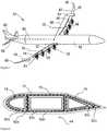
- Figs. 1 to 5show an aircraft 40 in accordance with the present disclosure.
- the aircraft 40comprises a fuselage 42, a pair of wings 44 extending therefrom generally normal to the fuselage 42 along an axis 68, and an empennage located at an aft end of the fuselage 42 which defines a longitudinal axis 64.
- the empennagecomprises vertical and horizontal tailplanes 60, 66.
- a wingspanis defined by the distance between wing tips 49.
- Each wing 44comprises a leading edge 45 and a trailing edge 47, which together define a chord extending therebetween.
- the ratio between the wingspan and chord lengthdefines an aspect ratio.
- the chord lengthvaries along the wing span, from a relatively large chord at the wing root adjacent the fuselage 42, to a relatively small length at the wing tips 49.
- each wing 44preferably further comprises a deployable high lift device in the form of flaps 52 located at the trailing edge 47 of each wing 44.
- the deployable high lift devicemay include one or more slats (not shown) located at the leading edge 45 of the wing.
- the flaps 52are selectable between a stowed position (as shown in Fig.
- the deployable high lift devicesmay be deployable to intermediate positions between the deployed and stowed positions.
- a plurality of propulsors 46is provided on each wing 44, which provide thrust to drive the aircraft forward.
- the plurality of propulsors 46 on each wingtogether define a centre of thrust 70, i.e. a notional line extending rearwardly from the centre of the airflow provided by the propulsors 46 on that wing 44.
- four propulsorsare provided, though more or fewer propulsors may in some cases be provided.
- the relatively large number of propulsors 46enables a relatively large propulsor disc area to be employed. Consequently, the propulsors are highly efficient and relatively quiet, without requiring excessive ground clearance, which thereby reduces the length of the undercarriage.
- Each propulsor 46comprises an electric motor 51 housed within a nacelle 48, and a propeller 50 driven by the motor 51, though other forms of propulsors such as electrically driven ducted fans driven by the motors 51 could be employed.
- Each propeller 50is located forward of the leading edge 45 of the wing 44, and is mounted to the wing 44 by the nacelle 48. In use, the propellers 50 rotate to provide airflow, and therefore thrust. As the propellers 50 are located forward of the leading edge 45, the airflow travels over the portion of the wing 44 located behind the respective propellers 50, and in particular over the flaps 52.
- This airflowincreases the effective airflow over the wing 44, thereby increasing the coefficient of lift (CL) when the propellers 50 are turning, and particularly where the flaps 52 are extended.
- the propellers 50are relatively closely spaced, such that the propellers 50 provide airflow over a large proportion of the wing 44, and particularly, the portion of the wing on which the flaps 52 are located.
- the maximum coefficient of lift of each wing 44 when the flaps 52 are deployed, and the propulsors 46 are at maximum power(C Lmax(power on )) is approximately twice the maximum coefficient of lift of each wing 44 when the propulsors 46 are at minimum power (C Lmax(power off) ), i.e. when the propulsors 46 are turned off. Consequently, the propulsors 46 substantially increase the amount of lift generated by the wings 44, thereby reducing the wing area required for a given amount of lift, or increasing the amount of lift for a given wing area.
- Each wing further 44comprises a generator arrangement 54, shown in further detail in figure 4 .
- the generator arrangement 54comprises an internal combustion engine in the form of a gas turbine engine 10 and an alternating current (AC) electrical power generator 56 driven by the engine 10.
- ACalternating current
- the engine 10drives the electrical power generator 56 to provide electrical power.
- An electrical energy storage devicesuch as a capacitor, chemical battery or hydrogen fuel cell 96 is included, which can be charged by the generator 56 to provide power to the propulsors 50 for a short period on engine failure or to improve performance for short duration flight segments such as e.g. takeoff or climb. Power is distributed to the electrical motors 51 which drive the propulsors 50 via a plurality of conductors 100.
- an electrical generator 56which produces electrical power at a relatively high AC frequency, such as 360 to 2000 Hz, which corresponds to the frequency generated by a three-phase generator driven directly by the low pressure shaft of a typical two shaft or three shaft gas turbine engine.
- a relatively high AC frequencysuch as 360 to 2000 Hz
- the skin depth of conductors carrying such high frequency electrical poweris relatively small - of the order of a few millimetres, as shown below.
- the resistivity of aluminium 2024 alloy typically used in aircraft constructionvaries between 3 and 4 ⁇ 10 -8 ⁇ m, the relative magnetic permeability is approximately 1, the permeability of free space is 4 ⁇ ⁇ 10 -7 Hm -1 , and the maximum angular frequency of the current in this example is approximately 5000 (800 ⁇ 2 ⁇ ). Consequently, the skin depth in this example would be approximately 3mm. Consequently, a solid cable carrying this current would either have a relatively high resistance in view of the relatively small effective cross sectional area of the conductor, or a relatively large diameter, and so a relatively high weight, much of which would not carry a significant portion of the current.
- FIG. 2shows a cross sectional view through part of the wing 44.
- the wingcomprises an outer skin 72, which provides an outer aerodynamic surface over which air flows in flight.
- a load bearing structural arrangementcomprising a plurality of hollow tubular structural members in the form of a leading edge (also known as a D-box), centre and trailing edge wing boxes 74, 76, 78.
- Further load bearing hollow tubular structuresmay be provided, such as ribs (which generally run in a chordwise direction, i.e. between the leading and trailing edges of the wing 44), and longerons (which generally attach the skin 72 to the ribs, and run in a spanwise direction, i.e. in a direction running between the root and the tip of the wing 44).
- Each of the hollow members 74, 76, 78is hollow, and made from an electrically conductive structural metal alloy such as aluminium. Consequently, one or more of the hollow structural members can be used as a conductor.
- the members 74, 76, 78may have any of a tubular, triangular, D-shaped, or box section cross section, or any other cross section as would be appropriate in view of the local shape of the surrounding skin, and structural considerations.
- each hollow member 74, 76, 78is divided into two electrical elements, each carrying a separate phase of the AC electrical power.
- the D-box section 74comprises a first current carrying element 80a (shown as the shaded portion in figure 2 ) and a ground / current return path element 82a (shown as the white portion in figure 2 ) are provided, with one being provided concentrically within the other.
- the hollow members 76, 68comprise second and third current carrying elements 80a, 80b respectively, and second and third ground elements 82, 82c respectively.
- the conductive elements 80a-c, 82a-care separated by an insulating material, such as NomexTM, to prevent short circuiting.
- a further layer of insulating materialis provided between the outer element 82a-c and the skin 72, again, to prevent short circuits. Consequently, the hollow member 74 is capable of carrying a complete circuit of a two-phase network.
- the hollow elements 74, 76, 78together carry a three-phases electrical network, with redundant current return paths.
- each hollow member 74, 76, 78could be divided into three elements, with insulation being provided between each element, in which case each hollow member 74, 76, 78 could be used to carry three phase electrical power.
- each hollow member 74, 76, 78could be formed of a single conductive element, with two or more hollow members 74, 76, 78 being separated by an electrical insulator, and each carrying a separate electrical phase.
- FIG. 3shows a perspective view of the D-box 74, illustrating the electrical connections between the generator 56 and drive motors 51.
- the D-box 74includes a projection 84 which extends from the leading edge of the D-box in a forward, chordal direction (i.e. from the leading edge of the wing).
- the projection 84leads to the electrical motor 51, and thereby connects the generator 56 to one of the motors 514.
- the electrical circuitcan be provided without any overlapping of the elements 80, 82, thereby simplifying construction.
- FIG. 5shows an alternative embodiment, showing an alternative current carrying element 180.
- each current carrying element 180comprises a plurality of electrically conductive filaments 186, 188, 190, which are spirally wound to define a multi-start helix.
- the spirally wound filamentsare be embedded within a matrix such as an epoxy 192, such that the current carrying element 180 comprises a composite material having a high strength to weight ratio and flexibility.
- the current carrying elementis tubular, defining a hollow space therein, in which further current carrying elements can be contained.
- each electrical element 180may comprise a plurality of sub-elements in the form of filaments 186, 188, 190.
- One of more of these sub-elementsmay be electrically connected to another sub-element, or may be electrically independent of one or more other sub-element.
- each of the filaments 186, 188, 190may carry the same phase between the generator 56 and motor 51, thereby providing redundancy in the event of failure of one or more of the other filaments 186, 188, 190 within that element 180.
- Connectors(not shown) to each filament 186, 188, 190 could be provided extending radially from the filaments, or at each end.
- the connectorsmay comprise current interruption devices such as circuit breakers, which would interrupt current flow in the event of an electrical malfunction.
- each of the filaments 186, 188, 190could carry a separate electrical phase. In such a case, only a single tubular electrical element might be provided.
- the arrangement of the present inventionprovides a synergy, in that the hollow structural members provide both a load carrying, and an electrical power carrying function. Meanwhile, the hollow structural members provide an efficient means of bearing the bending and compressive loads experienced by the aircraft, and an efficient means of transmitting electrical power (in terms of weight and electrical resistance) in view of their hollow, tubular arrangement.
- solid electrical cableswould provide relatively low efficiency electrical power transmission (in view of having a small diameter and therefore high resistance, or a large diameter and therefore high weight), while also being poor load bearing elements for all but tensile loads, whereas aircraft load bearing elements typically require transmission of bending loads.
- the structureis essentially of a composite nature. Consequently, the insulating material such as Nomex TM may provide compressive strength, while the layers of conductive metallic material may provide tensile and bending strength. Consequently, the hollow structural members may provide improved structural properties compared to prior structural members.
- resistive heating caused by the elementsmay help reduce wing icing at the leading edge.
- Currentmay be maintained within these conductors during times of non-operation of the motors by windmilling one or more propulsors, such that the propulsor motors act as generators.
- increased currentcould be provided for de-icing by short-circuiting one or more electrical conductors.
- the electrically conducting hollow structural elementsmay also be used to transmit control signals and other data, for example using frequency or pulse modulation of the electrical current.
- the networkcould comprise an impedance sensor configured to measure electrical impedance between two or more electrical conductors.
- an impedance sensorconfigured to measure electrical impedance between two or more electrical conductors.
- physical separation / delamination between layerscould be detected by measuring conductor electrical impedance, due to the resulting increase in dielectric constant between phases where the gap between conductors is increased.
- generators and propulsorsare provided, it will be understood that these are only examples of a broader class of suitable equipment.
- generators and propulsorscould be used, such as induction generators and motors.
- propulsorscould be used, such as ducted fans.
- the electrical conductorscould be utilised to power other aircraft equipment, such as actuators, sensors, aircraft environmental control equipment, etc.
- the conductorscould carry electrical signals from sensors distributed about the aircraft.
- the structural conductorcould comprise further conductive layers which are not connected to electrical equipment, in order to provide electrical field shield and / or lightning protection.
- the inventionis applicable to different aircraft configurations.
- the propulsorscould be provided in different locations, such as at the trailing edge of the wing or the aft end of the fuselage.
- the inventionis applicable to so-called "blended wing body" aircraft, which do not possess distinct fuselage and wings.
Landscapes
- Engineering & Computer Science (AREA)
- Aviation & Aerospace Engineering (AREA)
- Mechanical Engineering (AREA)
- Wind Motors (AREA)
Description
- The present invention relates to an aircraft electrical network, particularly, though not exclusively, to an aircraft electrical network for an aircraft comprising electrically driven propulsors.
- In view of increasing energy costs, there is a continuing need to provide aircraft which burn less fuel for a given set of requirements. In co-pending UK patent application
GB 1320988.7 - However, in order for the aircraft to remain competitive compared to a conventional aircraft, it is necessary for the electrical generators and associated electrical transmission arrangement to be as light as possible, while generating and transmitting electrical power with as few losses as possible.
EP2878538 discloses an aircraft comprising a propulsion system. The propulsion system comprises a pair of internal combustion engines, each driving an electrical power generator. Each electrical power generator is electrically coupled to a plurality of electrically driven propulsors. The propulsors are located forward of a leading edge of the wings such that an airstream generated by the propulsors flows over the wings in use. Each internal combustion engine and electrical generator is mounted on a respective wing outboard of a centre of thrust of the propulsors on that wing.US2015344138 discloses a multi-functional composite system. The system comprises a core, a plurality of structural composite fiber layers, a matrix material, and a composite conductor assembly. The composite conductor assembly has one or more conductors disposed between two or more insulating layers, and an electric power source electronically coupled with said composite conductor assembly. The electric power source is configured to pass electric current through at least one of said one or more conductors.- The present invention describes an aircraft electrical transmission network which seeks to overcome some or all of the above problems.
- According to a first aspect of the present invention, there is provided an aircraft comprising an internal combustion engine and a wing comprising a hollow structural member comprising any of a wing leading edge box, a wing centre box, and a wing trailing edge box, wherein the aircraft comprises an electrical network comprising:
- at least one alternating current electrical generator configured to be driven by the internal combustion engine;
- an electrical motor configured to drive an aircraft propulsor;
- at least one conductor configured to electrically couple the electrical motor and the electrical generator the conductor comprising at least two conducting elements carrying a separate electrical phase, and each current carrying element being arranged concentrically;
- wherein the electrical conductor is formed of the hollow structural member of the aircraft wing.
- Accordingly, electrical power can be transmitted by a hollow structural member comprising any of a wing leading edge box, a wing centre box, and a wing trailing edge box. In view of the relatively high frequency and high power of the electrical power transmitted between the generator and the electrical motors, it is desirable for the conductor to be hollow, in view of the relatively small skin depth of the current in such circumstances. By using a hollow structural member as the conductor, a low resistance conductor can be provided, without significantly increasing the weight of the aircraft structure, since the conductor provides part of the structural integrity of the aircraft.
- The conductor may comprise a conductive coating provided on a surface of the hollow structural member. Alternatively or in addition, the hollow structural member may comprise a conductive material such as aluminium, and may provide a conductive path of the conductor.
- Preferably, the hollow structural member comprises a wing leading edge D-box.
- The conductor may comprise a current carrying element and a current return / ground element.
- The conductor may comprise one or more insulators configured to insulate the conductor from surrounding structure, and / or insulate the current carrying element from the current return / ground element.
- The alternating current electrical generator may be configured to provide electrical current having a frequency between 360 and 2000Hz.
Figure 1 shows a perspective view of an aircraft in accordance with the present disclosure comprising an electrical network in accordance with the present disclosure;Figure 2 shows a cross sectional view through an aerofoil of an aircraft in accordance with the present disclosure;Figure 3 shows a perspective cross sectional view through the aerofoil offigure 2 ;Figure 4 shows a schematic electrical diagram of a propulsion system of the aircraft offigure 1 ; andFigure 5 shows a perspective cross sectional view through part of an alternative current carrying element.Figs. 1 to 5 show anaircraft 40 in accordance with the present disclosure. Theaircraft 40 comprises afuselage 42, a pair ofwings 44 extending therefrom generally normal to thefuselage 42 along anaxis 68, and an empennage located at an aft end of thefuselage 42 which defines alongitudinal axis 64. The empennage comprises vertical andhorizontal tailplanes - A wingspan is defined by the distance between
wing tips 49. Eachwing 44 comprises a leadingedge 45 and atrailing edge 47, which together define a chord extending therebetween. The ratio between the wingspan and chord length defines an aspect ratio. As can be seen fromFig. 2 , the chord length varies along the wing span, from a relatively large chord at the wing root adjacent thefuselage 42, to a relatively small length at thewing tips 49. In cases such as this where the chord varies along the span, the aspect ratio AR can be defined as the square of the wingspan b divided by the area S of the wing planform:
- In the example shown in
Fig. 2 , the aspect ratio is approximately 25, though higher aspect ratios such as aspect ratios up to 30 or more may be achieved. In other cases, lower aspect ratios may be desirable, such as where the aircraft comprises a short takeoff and landing aircraft (STOL). Eachwing 44 preferably further comprises a deployable high lift device in the form offlaps 52 located at thetrailing edge 47 of eachwing 44. Optionally, the deployable high lift device may include one or more slats (not shown) located at the leadingedge 45 of the wing. Theflaps 52 are selectable between a stowed position (as shown inFig. 2 ) and a deployed position, in which theflaps 52 increase the lift coefficient of thewing 44 compared to when theflaps 52 are in the stowed position. The deployable high lift devices may be deployable to intermediate positions between the deployed and stowed positions. - A plurality of
propulsors 46 is provided on eachwing 44, which provide thrust to drive the aircraft forward. The plurality ofpropulsors 46 on each wing together define a centre ofthrust 70, i.e. a notional line extending rearwardly from the centre of the airflow provided by thepropulsors 46 on thatwing 44. In the described embodiment, four propulsors are provided, though more or fewer propulsors may in some cases be provided. The relatively large number ofpropulsors 46 enables a relatively large propulsor disc area to be employed. Consequently, the propulsors are highly efficient and relatively quiet, without requiring excessive ground clearance, which thereby reduces the length of the undercarriage. - Each
propulsor 46 comprises anelectric motor 51 housed within anacelle 48, and apropeller 50 driven by themotor 51, though other forms of propulsors such as electrically driven ducted fans driven by themotors 51 could be employed. Eachpropeller 50 is located forward of the leadingedge 45 of thewing 44, and is mounted to thewing 44 by thenacelle 48. In use, thepropellers 50 rotate to provide airflow, and therefore thrust. As thepropellers 50 are located forward of the leadingedge 45, the airflow travels over the portion of thewing 44 located behind therespective propellers 50, and in particular over theflaps 52. This airflow increases the effective airflow over thewing 44, thereby increasing the coefficient of lift (CL) when thepropellers 50 are turning, and particularly where theflaps 52 are extended. Thepropellers 50 are relatively closely spaced, such that thepropellers 50 provide airflow over a large proportion of thewing 44, and particularly, the portion of the wing on which theflaps 52 are located. - In the described embodiment, the maximum coefficient of lift of each
wing 44 when theflaps 52 are deployed, and thepropulsors 46 are at maximum power (CLmax(power on)) is approximately twice the maximum coefficient of lift of eachwing 44 when thepropulsors 46 are at minimum power (CLmax(power off)), i.e. when thepropulsors 46 are turned off. Consequently, thepropulsors 46 substantially increase the amount of lift generated by thewings 44, thereby reducing the wing area required for a given amount of lift, or increasing the amount of lift for a given wing area. - Each wing further 44 comprises a
generator arrangement 54, shown in further detail infigure 4 . Thegenerator arrangement 54 comprises an internal combustion engine in the form of agas turbine engine 10 and an alternating current (AC)electrical power generator 56 driven by theengine 10. In the described embodiment, a single generator arrangement is provided on eachwing 44, though further generator arrangements could be provided. Theengine 10 drives theelectrical power generator 56 to provide electrical power. An electrical energy storage device such as a capacitor, chemical battery orhydrogen fuel cell 96 is included, which can be charged by thegenerator 56 to provide power to thepropulsors 50 for a short period on engine failure or to improve performance for short duration flight segments such as e.g. takeoff or climb. Power is distributed to theelectrical motors 51 which drive thepropulsors 50 via a plurality ofconductors 100. - In order to generate electricity efficiently from the relatively high speed shafts of the engine, without recourse to relatively heavy and bulky reduction gearboxes, it is necessary to provide an
electrical generator 56 which produces electrical power at a relatively high AC frequency, such as 360 to 2000 Hz, which corresponds to the frequency generated by a three-phase generator driven directly by the low pressure shaft of a typical two shaft or three shaft gas turbine engine. In such cases, it can be shown that the skin depth of conductors carrying such high frequency electrical power is relatively small - of the order of a few millimetres, as shown below. - The skin depthδ is related to the angular frequency of the AC current ω (i.e. 2π × the frequency), resistivity of the conductor p, relative magnetic permeability of the conductor µr, and the permeability of free space µ0 in accordance with the following equation:

- The resistivity of aluminium 2024 alloy typically used in aircraft construction varies between 3 and 4 × 10⁻⁸ Ωm, the relative magnetic permeability is approximately 1, the permeability of free space is 4π × 10-7 Hm-1, and the maximum angular frequency of the current in this example is approximately 5000 (800 × 2π). Consequently, the skin depth in this example would be approximately 3mm. Consequently, a solid cable carrying this current would either have a relatively high resistance in view of the relatively small effective cross sectional area of the conductor, or a relatively large diameter, and so a relatively high weight, much of which would not carry a significant portion of the current.
Figure 2 shows a cross sectional view through part of thewing 44. As can be seen, the wing comprises anouter skin 72, which provides an outer aerodynamic surface over which air flows in flight. Enclosed within theskin 72 is a load bearing structural arrangement comprising a plurality of hollow tubular structural members in the form of a leading edge (also known as a D-box), centre and trailingedge wing boxes skin 72 to the ribs, and run in a spanwise direction, i.e. in a direction running between the root and the tip of the wing 44).- Each of the
hollow members members - As can be seen in
figure 2 , eachhollow member box section 74 comprises a first current carryingelement 80a (shown as the shaded portion infigure 2 ) and a ground / currentreturn path element 82a (shown as the white portion infigure 2 ) are provided, with one being provided concentrically within the other. Similarly, thehollow members elements third ground elements conductive elements 80a-c, 82a-c are separated by an insulating material, such as Nomex™, to prevent short circuiting. A further layer of insulating material is provided between theouter element 82a-c and theskin 72, again, to prevent short circuits. Consequently, thehollow member 74 is capable of carrying a complete circuit of a two-phase network. Thehollow elements hollow member hollow member hollow member hollow members Figure 3 shows a perspective view of the D-box 74, illustrating the electrical connections between thegenerator 56 and drivemotors 51. The D-box 74 includes aprojection 84 which extends from the leading edge of the D-box in a forward, chordal direction (i.e. from the leading edge of the wing). Theprojection 84 leads to theelectrical motor 51, and thereby connects thegenerator 56 to one of the motors 514. As can be seen, due to the concentric arrangement of theelements elements Figure 5 shows an alternative embodiment, showing an alternative current carryingelement 180. In this embodiment, each current carryingelement 180 comprises a plurality of electricallyconductive filaments element 180 comprises a composite material having a high strength to weight ratio and flexibility. As in the previous embodiment, the current carrying element is tubular, defining a hollow space therein, in which further current carrying elements can be contained.- Consequently, each
electrical element 180 may comprise a plurality of sub-elements in the form offilaments filaments generator 56 andmotor 51, thereby providing redundancy in the event of failure of one or more of theother filaments element 180. Connectors (not shown) to eachfilament - Alternatively, each of the
filaments - The arrangement of the present invention provides a synergy, in that the hollow structural members provide both a load carrying, and an electrical power carrying function. Meanwhile, the hollow structural members provide an efficient means of bearing the bending and compressive loads experienced by the aircraft, and an efficient means of transmitting electrical power (in terms of weight and electrical resistance) in view of their hollow, tubular arrangement. In contrast, solid electrical cables would provide relatively low efficiency electrical power transmission (in view of having a small diameter and therefore high resistance, or a large diameter and therefore high weight), while also being poor load bearing elements for all but tensile loads, whereas aircraft load bearing elements typically require transmission of bending loads.
- Furthermore, due to the layered construction of the tubular structural elements from different materials, the structure is essentially of a composite nature. Consequently, the insulating material such as Nomex ™ may provide compressive strength, while the layers of conductive metallic material may provide tensile and bending strength. Consequently, the hollow structural members may provide improved structural properties compared to prior structural members.
- Where the electrically conducting hollow structural elements are provided adjacent the leading edge of the wing (such as in the D-box), resistive heating caused by the elements may help reduce wing icing at the leading edge. Current may be maintained within these conductors during times of non-operation of the motors by windmilling one or more propulsors, such that the propulsor motors act as generators. Similarly, increased current could be provided for de-icing by short-circuiting one or more electrical conductors.
- The electrically conducting hollow structural elements may also be used to transmit control signals and other data, for example using frequency or pulse modulation of the electrical current.
- The network could comprise an impedance sensor configured to measure electrical impedance between two or more electrical conductors. Advantageously, physical separation / delamination between layers could be detected by measuring conductor electrical impedance, due to the resulting increase in dielectric constant between phases where the gap between conductors is increased.
- While the invention has been described in conjunction with the exemplary embodiments described above, many equivalent modifications and variations will be apparent to those skilled in the art when given this disclosure. Accordingly, the exemplary embodiments of the invention set forth above are considered to be illustrative and not limiting. Various changes to the described embodiments may be made without departing from the spirit and scope of the invention.
- Though particular examples of generators and propulsors are provided, it will be understood that these are only examples of a broader class of suitable equipment. For example, other types of electrical generators and motors could be used, such as induction generators and motors. Other forms of propulsors could be used, such as ducted fans.
- In addition to motors for powering electrical motors, the electrical conductors could be utilised to power other aircraft equipment, such as actuators, sensors, aircraft environmental control equipment, etc. Similarly, the conductors could carry electrical signals from sensors distributed about the aircraft.
- The structural conductor could comprise further conductive layers which are not connected to electrical equipment, in order to provide electrical field shield and / or lightning protection.
- In general, it will be appreciated that the invention is applicable to different aircraft configurations. For example, the propulsors could be provided in different locations, such as at the trailing edge of the wing or the aft end of the fuselage. Similarly, the invention is applicable to so-called "blended wing body" aircraft, which do not possess distinct fuselage and wings.
- Aspects of any of the embodiments of the invention could be combined with aspects of other embodiments, where appropriate.


Claims (5)
- An aircraft (40) comprising an internal combustion engine (10) and a wing (44) comprising a hollow structural member (74, 76, 78) comprising any of a wing leading edge box (74), a wing centre box (76), and a wing trailing edge box (78), wherein the aircraft (40) comprises an electrical network comprising:at least one alternating current electrical generator (56) configured to be driven by the internal combustion engine (10);an electrical motor (51) configured to drive an aircraft propulsor (46);at least one conductor (80, 82) configured to electrically couple the electrical motor (51) and the electrical generator (56), the conductor (80, 82) comprising at least two conducting elements (80a-c) carrying a separate electrical phase, and each current carrying element (80a-c) being arranged concentrically;wherein the electrical conductor (80, 82) is formed of the hollow structural member (74, 76, 78) of the aircraft wing (44).
- An aircraft according to claim 1, wherein the conductor (80, 82) comprises a conductive coating provided on a surface of the hollow structural member.
- An aircraft according to claim 1 or claim 2, wherein the hollow structural member (74, 76, 78) comprises a conductive material and provides a conductive path of the conductor (80, 82).
- An aircraft according to any of the preceding claims, wherein the conductor (80, 82) comprises one or more insulators configured to insulate the conductor (80, 82) from surrounding structure, and / or insulate the current carrying element from a current return / ground element (82a-c).
- An aircraft according to any of the preceding claims, wherein the alternating current electrical generator (56) is configured to provide electrical current having a frequency between 360 and 2000Hz.
Applications Claiming Priority (1)
| Application Number | Priority Date | Filing Date | Title |
|---|---|---|---|
| GB201607038 | 2016-04-22 |
Publications (2)
| Publication Number | Publication Date |
|---|---|
| EP3235723A1 EP3235723A1 (en) | 2017-10-25 |
| EP3235723B1true EP3235723B1 (en) | 2019-11-27 |
Family
ID=58530438
Family Applications (1)
| Application Number | Title | Priority Date | Filing Date |
|---|---|---|---|
| EP17165704.2AActiveEP3235723B1 (en) | 2016-04-22 | 2017-04-10 | Aircraft electrical network |
Country Status (2)
| Country | Link |
|---|---|
| US (2) | US10518863B2 (en) |
| EP (1) | EP3235723B1 (en) |
Families Citing this family (11)
| Publication number | Priority date | Publication date | Assignee | Title |
|---|---|---|---|---|
| US10457391B2 (en)* | 2016-03-15 | 2019-10-29 | Selex Galileo Inc. | Method and system for a small unmanned aerial system for delivering electronic warfare and cyber effects |
| EP3235723B1 (en)* | 2016-04-22 | 2019-11-27 | Rolls-Royce plc | Aircraft electrical network |
| US10392106B2 (en)* | 2016-09-08 | 2019-08-27 | General Electric Company | Tiltrotor propulsion system for an aircraft |
| US10384773B2 (en)* | 2016-09-08 | 2019-08-20 | General Electric Company | Tiltrotor propulsion system for an aircraft |
| US10252797B2 (en)* | 2016-09-08 | 2019-04-09 | General Electric Company | Tiltrotor propulsion system for an aircraft |
| FR3080607B1 (en)* | 2018-04-26 | 2020-10-02 | Safran | HYBRID PROPULSION SYSTEM FOR AN AIRCRAFT |
| EP3931091A4 (en)* | 2019-03-01 | 2023-01-11 | Pratt & Whitney Canada Corp. | DISTRIBUTED PROPULSION CONFIGURATIONS FOR AIRCRAFT WITH MIXED PROPULSION SYSTEMS |
| US20210070458A1 (en)* | 2019-09-06 | 2021-03-11 | Hamilton Sundstrand Corporation | Vortex turbines for a hybrid-electric aircraft |
| RU2752104C1 (en)* | 2020-02-25 | 2021-07-22 | Общество с ограниченной ответственностью "ПРОМСЕРВИС" | Short take-off and landing aircraft |
| GB202008876D0 (en)* | 2020-06-11 | 2020-07-29 | Rolls Royce Plc | Aircraft |
| US11834186B2 (en) | 2020-08-31 | 2023-12-05 | General Electric Company | Aircraft equipped with a distributed propulsion system having suction and pressure fans |
Family Cites Families (34)
| Publication number | Priority date | Publication date | Assignee | Title |
|---|---|---|---|---|
| GB213065A (en)* | 1923-02-07 | 1924-03-27 | Benjamin Shuttleworth Hornby | Improvements in and relating to the methods of transmitting multiphase alternating electric currents, through separate cables for each phase |
| US4605185A (en)* | 1983-10-17 | 1986-08-12 | Daniel Reyes | Airplane powered by vehicular motor |
| US5122072A (en)* | 1990-12-20 | 1992-06-16 | Square D Company | Cam-lock busway joint assembly |
| US7281681B2 (en)* | 2000-04-03 | 2007-10-16 | Aerovironment Inc. | Hydrogen powered aircraft |
| US6851929B2 (en)* | 2002-03-19 | 2005-02-08 | Hamilton Sundstrand | System for powering and controlling a device associated with a rotating component on aircraft |
| US7210653B2 (en)* | 2002-10-22 | 2007-05-01 | The Boeing Company | Electric-based secondary power system architectures for aircraft |
| US7608785B2 (en)* | 2004-04-27 | 2009-10-27 | Superpower, Inc. | System for transmitting current including magnetically decoupled superconducting conductors |
| JP4092728B2 (en)* | 2005-01-25 | 2008-05-28 | 独立行政法人 宇宙航空研究開発機構 | Aircraft propulsion system |
| US7319307B2 (en)* | 2005-12-16 | 2008-01-15 | General Electric Company | Power balancing of multiple synchronized generators |
| FR2899563B1 (en)* | 2006-04-11 | 2009-03-20 | Airbus France Sas | DEVICE AND METHOD FOR SUPPLYING ELECTRICAL RELIEF ON BOARD AN AIRCRAFT |
| FR2907762B1 (en)* | 2006-10-27 | 2009-12-18 | Airbus France | SYSTEM FOR GENERATING, CONVERTING, DISTRIBUTING AND ELECTRIC STARTING ABOARD AN AIRCRAFT |
| US20080184906A1 (en)* | 2007-02-07 | 2008-08-07 | Kejha Joseph B | Long range hybrid electric airplane |
| US7514806B2 (en)* | 2007-06-05 | 2009-04-07 | Honeywell International Inc. | Engine start system with quadrature AC excitation |
| US7687927B2 (en)* | 2007-11-21 | 2010-03-30 | The Boeing Company | Electrical systems architecture for an aircraft, and related operating methods |
| FR2948337B1 (en)* | 2009-07-24 | 2011-07-29 | Aircelle Sa | ELECTRIC POWER SUPPLY CIRCUIT FOR TURBOREACTOR NACELLE |
| US8294316B2 (en)* | 2009-07-28 | 2012-10-23 | Rolls-Royce North American Technologies, Inc. | Electrical power generation apparatus for contra-rotating open-rotor aircraft propulsion system |
| US8772997B2 (en)* | 2010-09-13 | 2014-07-08 | Baker Hughes Incorporated | Electrical submersible pump system having high temperature slot, end bell and phase-to-phase insulation |
| US9212625B2 (en)* | 2010-11-19 | 2015-12-15 | Rudolph Allen SHELLEY | Hybrid gas turbine propulsion system |
| FR2978878B1 (en)* | 2011-08-04 | 2013-08-09 | Hispano Suiza Sa | DEVICE FOR ELECTRICALLY SUPPLYING AN AIRCRAFT TO THE GROUND. |
| FR2988694B1 (en)* | 2012-03-30 | 2014-03-28 | Hispano Suiza Sa | DEVICE FOR ELECTRICALLY SUPPLYING AN AIRCRAFT ON THE GROUND |
| GB201308292D0 (en)* | 2013-05-09 | 2013-06-12 | Rolls Royce Plc | Aircraft electrical system |
| FR3006997B1 (en)* | 2013-06-14 | 2016-12-23 | Airbus | AIRCRAFT WITH ELECTRICAL PROPULSION MEANS |
| US10071801B2 (en)* | 2013-08-13 | 2018-09-11 | The United States Of America As Represented By The Administrator Of Nasa | Tri-rotor aircraft capable of vertical takeoff and landing and transitioning to forward flight |
| US9475579B2 (en)* | 2013-08-13 | 2016-10-25 | The United States Of America As Represented By The Administrator Of The National Aeronautics And Space Administration | Vertical take-off and landing vehicle with increased cruise efficiency |
| GB201320988D0 (en)* | 2013-11-28 | 2014-01-15 | Rolls Royce Plc | An aircraft |
| GB201403178D0 (en)* | 2014-02-24 | 2014-04-09 | Rolls Royce Plc | Electrical power generator for a gas turbine engine |
| US10368401B2 (en)* | 2014-06-03 | 2019-07-30 | Aurora Flight Sciences Corporation | Multi-functional composite structures |
| GB201508138D0 (en)* | 2015-05-13 | 2015-06-24 | Rolls Royce Plc | Aircraft |
| GB201511033D0 (en)* | 2015-05-19 | 2015-08-05 | Rolls Royce Plc | Aircraft electrical network |
| KR20180093872A (en)* | 2015-08-11 | 2018-08-22 | 제네시스 로보틱스 엘엘피 | Electric machine |
| EP3232549B1 (en)* | 2016-04-14 | 2020-12-16 | Levitronix GmbH | Electromagnetic rotary drive and rotary device |
| EP3235723B1 (en)* | 2016-04-22 | 2019-11-27 | Rolls-Royce plc | Aircraft electrical network |
| US10252797B2 (en)* | 2016-09-08 | 2019-04-09 | General Electric Company | Tiltrotor propulsion system for an aircraft |
| US10273019B2 (en)* | 2017-03-06 | 2019-04-30 | Rolls-Royce Corporation | Distributed propulsion system power unit control |
- 2017
- 2017-04-10EPEP17165704.2Apatent/EP3235723B1/enactiveActive
- 2017-04-10USUS15/483,721patent/US10518863B2/enactiveActive
- 2019
- 2019-10-21USUS16/658,432patent/US10737759B2/enactiveActive
Non-Patent Citations (1)
| Title |
|---|
| None* |
Also Published As
| Publication number | Publication date |
|---|---|
| US20200047871A1 (en) | 2020-02-13 |
| US10737759B2 (en) | 2020-08-11 |
| EP3235723A1 (en) | 2017-10-25 |
| US20170305524A1 (en) | 2017-10-26 |
| US10518863B2 (en) | 2019-12-31 |
Similar Documents
| Publication | Publication Date | Title |
|---|---|---|
| US10737759B2 (en) | Aircraft electrical network | |
| US12391391B2 (en) | Propulsion system and methods of use thereof | |
| US12370908B2 (en) | Propulsion system for an aircraft | |
| EP2878538B1 (en) | An aircraft | |
| US10759545B2 (en) | Hybrid electric aircraft system with distributed propulsion | |
| US20210214094A1 (en) | Aircraft propulsion system | |
| US11121557B2 (en) | Power distribution system for aircraft | |
| Jansen et al. | Sizing power components of an electrically driven tail cone thruster and a range extender | |
| RU2724940C2 (en) | Vertical take-off and landing aircraft with hybrid power plant | |
| Isikveren et al. | Conceptual studies of universally-electric systems architectures suitable for transport aircraft | |
| US20150151844A1 (en) | Hybrid aircraft | |
| US20110147511A1 (en) | Rotating wing aircraft with tip-driven rotor and rotor-guide ring | |
| CN103153788A (en) | Method and apparatus for deicing structural elements | |
| CN110683050A (en) | Aircraft with a flight control device | |
| US12249831B2 (en) | Electrically driven distributed propulsion system | |
| Lawhorn et al. | Electric aircraft system co-simulation including body, propeller, propulsion, and energy storage models | |
| EP2520492B1 (en) | Ice protection system | |
| US12199541B2 (en) | Systems and methods for electric damping of aircraft flight control surfaces and propellers | |
| EP3462563B1 (en) | Electrical interconnect system of a vehicle | |
| CN118004469A (en) | Electric aircraft | |
| Buzuluk et al. | Multi-rotor helicopter type platform capacities research | |
| DE102022204760A1 (en) | Electrical arrangement for an aircraft | |
| Dunn | Electric aircraft on the horizon |
Legal Events
| Date | Code | Title | Description |
|---|---|---|---|
| PUAI | Public reference made under article 153(3) epc to a published international application that has entered the european phase | Free format text:ORIGINAL CODE: 0009012 | |
| STAA | Information on the status of an ep patent application or granted ep patent | Free format text:STATUS: THE APPLICATION HAS BEEN PUBLISHED | |
| AK | Designated contracting states | Kind code of ref document:A1 Designated state(s):AL AT BE BG CH CY CZ DE DK EE ES FI FR GB GR HR HU IE IS IT LI LT LU LV MC MK MT NL NO PL PT RO RS SE SI SK SM TR | |
| AX | Request for extension of the european patent | Extension state:BA ME | |
| STAA | Information on the status of an ep patent application or granted ep patent | Free format text:STATUS: REQUEST FOR EXAMINATION WAS MADE | |
| 17P | Request for examination filed | Effective date:20180309 | |
| RBV | Designated contracting states (corrected) | Designated state(s):AL AT BE BG CH CY CZ DE DK EE ES FI FR GB GR HR HU IE IS IT LI LT LU LV MC MK MT NL NO PL PT RO RS SE SI SK SM TR | |
| REG | Reference to a national code | Ref country code:DE Ref legal event code:R079 Ref document number:602017009009 Country of ref document:DE Free format text:PREVIOUS MAIN CLASS: B64C0003180000 Ipc:B64C0003000000 | |
| RIC1 | Information provided on ipc code assigned before grant | Ipc:B64C 3/34 20060101ALI20190722BHEP Ipc:B64D 27/02 20060101ALI20190722BHEP Ipc:B64D 27/12 20060101ALI20190722BHEP Ipc:B64D 27/24 20060101ALI20190722BHEP Ipc:B64C 3/00 20060101AFI20190722BHEP Ipc:B64C 3/18 20060101ALI20190722BHEP | |
| GRAP | Despatch of communication of intention to grant a patent | Free format text:ORIGINAL CODE: EPIDOSNIGR1 | |
| STAA | Information on the status of an ep patent application or granted ep patent | Free format text:STATUS: GRANT OF PATENT IS INTENDED | |
| INTG | Intention to grant announced | Effective date:20190830 | |
| GRAS | Grant fee paid | Free format text:ORIGINAL CODE: EPIDOSNIGR3 | |
| GRAA | (expected) grant | Free format text:ORIGINAL CODE: 0009210 | |
| STAA | Information on the status of an ep patent application or granted ep patent | Free format text:STATUS: THE PATENT HAS BEEN GRANTED | |
| AK | Designated contracting states | Kind code of ref document:B1 Designated state(s):AL AT BE BG CH CY CZ DE DK EE ES FI FR GB GR HR HU IE IS IT LI LT LU LV MC MK MT NL NO PL PT RO RS SE SI SK SM TR | |
| REG | Reference to a national code | Ref country code:GB Ref legal event code:FG4D | |
| REG | Reference to a national code | Ref country code:CH Ref legal event code:EP | |
| REG | Reference to a national code | Ref country code:AT Ref legal event code:REF Ref document number:1206378 Country of ref document:AT Kind code of ref document:T Effective date:20191215 | |
| REG | Reference to a national code | Ref country code:DE Ref legal event code:R096 Ref document number:602017009009 Country of ref document:DE | |
| REG | Reference to a national code | Ref country code:IE Ref legal event code:FG4D | |
| RAP2 | Party data changed (patent owner data changed or rights of a patent transferred) | Owner name:ROLLS-ROYCE PLC | |
| REG | Reference to a national code | Ref country code:NL Ref legal event code:MP Effective date:20191127 | |
| REG | Reference to a national code | Ref country code:LT Ref legal event code:MG4D | |
| PG25 | Lapsed in a contracting state [announced via postgrant information from national office to epo] | Ref country code:LV Free format text:LAPSE BECAUSE OF FAILURE TO SUBMIT A TRANSLATION OF THE DESCRIPTION OR TO PAY THE FEE WITHIN THE PRESCRIBED TIME-LIMIT Effective date:20191127 Ref country code:SE Free format text:LAPSE BECAUSE OF FAILURE TO SUBMIT A TRANSLATION OF THE DESCRIPTION OR TO PAY THE FEE WITHIN THE PRESCRIBED TIME-LIMIT Effective date:20191127 Ref country code:BG Free format text:LAPSE BECAUSE OF FAILURE TO SUBMIT A TRANSLATION OF THE DESCRIPTION OR TO PAY THE FEE WITHIN THE PRESCRIBED TIME-LIMIT Effective date:20200227 Ref country code:NO Free format text:LAPSE BECAUSE OF FAILURE TO SUBMIT A TRANSLATION OF THE DESCRIPTION OR TO PAY THE FEE WITHIN THE PRESCRIBED TIME-LIMIT Effective date:20200227 Ref country code:FI Free format text:LAPSE BECAUSE OF FAILURE TO SUBMIT A TRANSLATION OF THE DESCRIPTION OR TO PAY THE FEE WITHIN THE PRESCRIBED TIME-LIMIT Effective date:20191127 Ref country code:NL Free format text:LAPSE BECAUSE OF FAILURE TO SUBMIT A TRANSLATION OF THE DESCRIPTION OR TO PAY THE FEE WITHIN THE PRESCRIBED TIME-LIMIT Effective date:20191127 Ref country code:LT Free format text:LAPSE BECAUSE OF FAILURE TO SUBMIT A TRANSLATION OF THE DESCRIPTION OR TO PAY THE FEE WITHIN THE PRESCRIBED TIME-LIMIT Effective date:20191127 Ref country code:GR Free format text:LAPSE BECAUSE OF FAILURE TO SUBMIT A TRANSLATION OF THE DESCRIPTION OR TO PAY THE FEE WITHIN THE PRESCRIBED TIME-LIMIT Effective date:20200228 | |
| PG25 | Lapsed in a contracting state [announced via postgrant information from national office to epo] | Ref country code:RS Free format text:LAPSE BECAUSE OF FAILURE TO SUBMIT A TRANSLATION OF THE DESCRIPTION OR TO PAY THE FEE WITHIN THE PRESCRIBED TIME-LIMIT Effective date:20191127 Ref country code:HR Free format text:LAPSE BECAUSE OF FAILURE TO SUBMIT A TRANSLATION OF THE DESCRIPTION OR TO PAY THE FEE WITHIN THE PRESCRIBED TIME-LIMIT Effective date:20191127 Ref country code:IS Free format text:LAPSE BECAUSE OF FAILURE TO SUBMIT A TRANSLATION OF THE DESCRIPTION OR TO PAY THE FEE WITHIN THE PRESCRIBED TIME-LIMIT Effective date:20200327 | |
| PG25 | Lapsed in a contracting state [announced via postgrant information from national office to epo] | Ref country code:AL Free format text:LAPSE BECAUSE OF FAILURE TO SUBMIT A TRANSLATION OF THE DESCRIPTION OR TO PAY THE FEE WITHIN THE PRESCRIBED TIME-LIMIT Effective date:20191127 | |
| PG25 | Lapsed in a contracting state [announced via postgrant information from national office to epo] | Ref country code:PT Free format text:LAPSE BECAUSE OF FAILURE TO SUBMIT A TRANSLATION OF THE DESCRIPTION OR TO PAY THE FEE WITHIN THE PRESCRIBED TIME-LIMIT Effective date:20200419 Ref country code:EE Free format text:LAPSE BECAUSE OF FAILURE TO SUBMIT A TRANSLATION OF THE DESCRIPTION OR TO PAY THE FEE WITHIN THE PRESCRIBED TIME-LIMIT Effective date:20191127 Ref country code:RO Free format text:LAPSE BECAUSE OF FAILURE TO SUBMIT A TRANSLATION OF THE DESCRIPTION OR TO PAY THE FEE WITHIN THE PRESCRIBED TIME-LIMIT Effective date:20191127 Ref country code:CZ Free format text:LAPSE BECAUSE OF FAILURE TO SUBMIT A TRANSLATION OF THE DESCRIPTION OR TO PAY THE FEE WITHIN THE PRESCRIBED TIME-LIMIT Effective date:20191127 Ref country code:ES Free format text:LAPSE BECAUSE OF FAILURE TO SUBMIT A TRANSLATION OF THE DESCRIPTION OR TO PAY THE FEE WITHIN THE PRESCRIBED TIME-LIMIT Effective date:20191127 Ref country code:DK Free format text:LAPSE BECAUSE OF FAILURE TO SUBMIT A TRANSLATION OF THE DESCRIPTION OR TO PAY THE FEE WITHIN THE PRESCRIBED TIME-LIMIT Effective date:20191127 | |
| REG | Reference to a national code | Ref country code:DE Ref legal event code:R097 Ref document number:602017009009 Country of ref document:DE | |
| PG25 | Lapsed in a contracting state [announced via postgrant information from national office to epo] | Ref country code:SM Free format text:LAPSE BECAUSE OF FAILURE TO SUBMIT A TRANSLATION OF THE DESCRIPTION OR TO PAY THE FEE WITHIN THE PRESCRIBED TIME-LIMIT Effective date:20191127 Ref country code:SK Free format text:LAPSE BECAUSE OF FAILURE TO SUBMIT A TRANSLATION OF THE DESCRIPTION OR TO PAY THE FEE WITHIN THE PRESCRIBED TIME-LIMIT Effective date:20191127 | |
| REG | Reference to a national code | Ref country code:AT Ref legal event code:MK05 Ref document number:1206378 Country of ref document:AT Kind code of ref document:T Effective date:20191127 | |
| PLBE | No opposition filed within time limit | Free format text:ORIGINAL CODE: 0009261 | |
| STAA | Information on the status of an ep patent application or granted ep patent | Free format text:STATUS: NO OPPOSITION FILED WITHIN TIME LIMIT | |
| 26N | No opposition filed | Effective date:20200828 | |
| PG25 | Lapsed in a contracting state [announced via postgrant information from national office to epo] | Ref country code:SI Free format text:LAPSE BECAUSE OF FAILURE TO SUBMIT A TRANSLATION OF THE DESCRIPTION OR TO PAY THE FEE WITHIN THE PRESCRIBED TIME-LIMIT Effective date:20191127 Ref country code:AT Free format text:LAPSE BECAUSE OF FAILURE TO SUBMIT A TRANSLATION OF THE DESCRIPTION OR TO PAY THE FEE WITHIN THE PRESCRIBED TIME-LIMIT Effective date:20191127 Ref country code:PL Free format text:LAPSE BECAUSE OF FAILURE TO SUBMIT A TRANSLATION OF THE DESCRIPTION OR TO PAY THE FEE WITHIN THE PRESCRIBED TIME-LIMIT Effective date:20191127 Ref country code:MC Free format text:LAPSE BECAUSE OF FAILURE TO SUBMIT A TRANSLATION OF THE DESCRIPTION OR TO PAY THE FEE WITHIN THE PRESCRIBED TIME-LIMIT Effective date:20191127 | |
| REG | Reference to a national code | Ref country code:CH Ref legal event code:PL | |
| PG25 | Lapsed in a contracting state [announced via postgrant information from national office to epo] | Ref country code:LI Free format text:LAPSE BECAUSE OF NON-PAYMENT OF DUE FEES Effective date:20200430 Ref country code:LU Free format text:LAPSE BECAUSE OF NON-PAYMENT OF DUE FEES Effective date:20200410 Ref country code:CH Free format text:LAPSE BECAUSE OF NON-PAYMENT OF DUE FEES Effective date:20200430 Ref country code:IT Free format text:LAPSE BECAUSE OF FAILURE TO SUBMIT A TRANSLATION OF THE DESCRIPTION OR TO PAY THE FEE WITHIN THE PRESCRIBED TIME-LIMIT Effective date:20191127 | |
| REG | Reference to a national code | Ref country code:BE Ref legal event code:MM Effective date:20200430 | |
| PG25 | Lapsed in a contracting state [announced via postgrant information from national office to epo] | Ref country code:BE Free format text:LAPSE BECAUSE OF NON-PAYMENT OF DUE FEES Effective date:20200430 | |
| PG25 | Lapsed in a contracting state [announced via postgrant information from national office to epo] | Ref country code:IE Free format text:LAPSE BECAUSE OF NON-PAYMENT OF DUE FEES Effective date:20200410 | |
| PG25 | Lapsed in a contracting state [announced via postgrant information from national office to epo] | Ref country code:TR Free format text:LAPSE BECAUSE OF FAILURE TO SUBMIT A TRANSLATION OF THE DESCRIPTION OR TO PAY THE FEE WITHIN THE PRESCRIBED TIME-LIMIT Effective date:20191127 Ref country code:MT Free format text:LAPSE BECAUSE OF FAILURE TO SUBMIT A TRANSLATION OF THE DESCRIPTION OR TO PAY THE FEE WITHIN THE PRESCRIBED TIME-LIMIT Effective date:20191127 Ref country code:CY Free format text:LAPSE BECAUSE OF FAILURE TO SUBMIT A TRANSLATION OF THE DESCRIPTION OR TO PAY THE FEE WITHIN THE PRESCRIBED TIME-LIMIT Effective date:20191127 | |
| PG25 | Lapsed in a contracting state [announced via postgrant information from national office to epo] | Ref country code:MK Free format text:LAPSE BECAUSE OF FAILURE TO SUBMIT A TRANSLATION OF THE DESCRIPTION OR TO PAY THE FEE WITHIN THE PRESCRIBED TIME-LIMIT Effective date:20191127 | |
| P01 | Opt-out of the competence of the unified patent court (upc) registered | Effective date:20230528 | |
| PGFP | Annual fee paid to national office [announced via postgrant information from national office to epo] | Ref country code:DE Payment date:20250428 Year of fee payment:9 | |
| PGFP | Annual fee paid to national office [announced via postgrant information from national office to epo] | Ref country code:GB Payment date:20250422 Year of fee payment:9 | |
| PGFP | Annual fee paid to national office [announced via postgrant information from national office to epo] | Ref country code:FR Payment date:20250424 Year of fee payment:9 |