EP3235452B1 - Fluid delivery system for surgical instruments - Google Patents
Fluid delivery system for surgical instrumentsDownload PDFInfo
- Publication number
- EP3235452B1 EP3235452B1EP17169449.0AEP17169449AEP3235452B1EP 3235452 B1EP3235452 B1EP 3235452B1EP 17169449 AEP17169449 AEP 17169449AEP 3235452 B1EP3235452 B1EP 3235452B1
- Authority
- EP
- European Patent Office
- Prior art keywords
- leg
- teeth
- holes
- surgical fastener
- tooth
- Prior art date
- Legal status (The legal status is an assumption and is not a legal conclusion. Google has not performed a legal analysis and makes no representation as to the accuracy of the status listed.)
- Active
Links
Images


Classifications
- A—HUMAN NECESSITIES
- A61—MEDICAL OR VETERINARY SCIENCE; HYGIENE
- A61B—DIAGNOSIS; SURGERY; IDENTIFICATION
- A61B17/00—Surgical instruments, devices or methods
- A61B17/12—Surgical instruments, devices or methods for ligaturing or otherwise compressing tubular parts of the body, e.g. blood vessels or umbilical cord
- A61B17/122—Clamps or clips, e.g. for the umbilical cord
- A—HUMAN NECESSITIES
- A61—MEDICAL OR VETERINARY SCIENCE; HYGIENE
- A61B—DIAGNOSIS; SURGERY; IDENTIFICATION
- A61B17/00—Surgical instruments, devices or methods
- A61B17/00491—Surgical glue applicators
- A—HUMAN NECESSITIES
- A61—MEDICAL OR VETERINARY SCIENCE; HYGIENE
- A61B—DIAGNOSIS; SURGERY; IDENTIFICATION
- A61B17/00—Surgical instruments, devices or methods
- A61B17/064—Surgical staples, i.e. penetrating the tissue
- A—HUMAN NECESSITIES
- A61—MEDICAL OR VETERINARY SCIENCE; HYGIENE
- A61B—DIAGNOSIS; SURGERY; IDENTIFICATION
- A61B17/00—Surgical instruments, devices or methods
- A61B17/064—Surgical staples, i.e. penetrating the tissue
- A61B17/0643—Surgical staples, i.e. penetrating the tissue with separate closing member, e.g. for interlocking with staple
- A—HUMAN NECESSITIES
- A61—MEDICAL OR VETERINARY SCIENCE; HYGIENE
- A61B—DIAGNOSIS; SURGERY; IDENTIFICATION
- A61B17/00—Surgical instruments, devices or methods
- A61B17/12—Surgical instruments, devices or methods for ligaturing or otherwise compressing tubular parts of the body, e.g. blood vessels or umbilical cord
- A61B17/128—Surgical instruments, devices or methods for ligaturing or otherwise compressing tubular parts of the body, e.g. blood vessels or umbilical cord for applying or removing clamps or clips
- A61B17/1285—Surgical instruments, devices or methods for ligaturing or otherwise compressing tubular parts of the body, e.g. blood vessels or umbilical cord for applying or removing clamps or clips for minimally invasive surgery
- A—HUMAN NECESSITIES
- A61—MEDICAL OR VETERINARY SCIENCE; HYGIENE
- A61B—DIAGNOSIS; SURGERY; IDENTIFICATION
- A61B17/00—Surgical instruments, devices or methods
- A61B2017/00831—Material properties
- A61B2017/00893—Material properties pharmaceutically effective
- Y—GENERAL TAGGING OF NEW TECHNOLOGICAL DEVELOPMENTS; GENERAL TAGGING OF CROSS-SECTIONAL TECHNOLOGIES SPANNING OVER SEVERAL SECTIONS OF THE IPC; TECHNICAL SUBJECTS COVERED BY FORMER USPC CROSS-REFERENCE ART COLLECTIONS [XRACs] AND DIGESTS
- Y10—TECHNICAL SUBJECTS COVERED BY FORMER USPC
- Y10T—TECHNICAL SUBJECTS COVERED BY FORMER US CLASSIFICATION
- Y10T24/00—Buckles, buttons, clasps, etc.
- Y10T24/44—Clasp, clip, support-clamp, or required component thereof
- Y10T24/44641—Clasp, clip, support-clamp, or required component thereof having gripping member formed from, biased by, or mounted on resilient member
- Y10T24/44744—Clasp, clip, support-clamp, or required component thereof having gripping member formed from, biased by, or mounted on resilient member with position locking-means for engaging faces
Definitions
- the present disclosurerelates to a fluid delivery system for surgical instruments. More particularly, the present disclosure relates to a fastener for releasing treatment material to clamped tissue.
- tissuesuch as, vascular tissues
- the proceduretypically involves placing clips or clamps within an applicator device and applying the clamps to the tissue on one side of an area, for example a diseased section of vascular tissue or colonic tissue, and placing another set of clamps on the opposing side of the diseased section. Thereafter, the diseased section can be excised and the resulting free ends of the tissue reattached.
- a mechanical fastening devicehaving a securing mechanism for maintaining the fastening devices in a closed position during the surgery. It is further desirable to provide a mechanical fastening device capable of applying medicament or treatment materials to the tissues during the surgery.
- the present inventionis defined in independent claim 1 and certain optional features thereof are defined in the dependent claims.
- the toothed fastenergenerally includes an upper leg and a lower leg, each of the upper and lower legs having a row of teeth, each tooth having a proximal face and a distal face.
- the toothed fastenerfurther includes a longitudinally extending securing member.
- a hole of predetermined diameteris formed in each of the proximal and distal faces and is of sufficient size to allow passage of the securing member therethrough.
- the upper or lower legsare movable from an open position to a closed position placing all the holes in longitudinal alignment such that the securing member can pass through all the holes in the teeth of the upper and lower legs.
- each toothhas a pair of spaced apart holes formed in each of the distal and proximal faces.
- the securing memberhas first and second legs for passage through the pair of spaced apart holes.
- the securing memberincludes a backspan such that the first and second legs extend distally from the backspan.
- the hole formed in the distal face of the distal most toothis sized to engage the securing member in a friction fit fashion.
- each of the teethare hollow or define a receptacle for receipt of material such that passage of the securing member through the holes of the teeth releases the material into the space between the first and second legs.
- the materialmay be contained within a puncturable capsule.
- each leghas a base, each base having an opening to the interior of the tooth for passage of material into the tooth.
- a membraneis provided covering the openings in each leg to retain the material within the teeth.
- a connectoris affixed to a proximal end of each of the first and second legs.
- the connectoris a living hinge.
- the living hingeis formed integrally with the proximal ends of the first and second legs.
- a system for applying a fastener to tissueincluding an applicator having a first and a second jaw and a toothed fastener positionable within the first and second jaws.
- the toothed fastenerincludes an upper leg and a lower leg, each of the upper and lower legs having a row of transverse, longitudinally extending teeth, each tooth having a proximal face and a distal face.
- the toothed fasteneralso includes a longitudinally extending securing member. A hole of predetermined diameter is formed in each of the proximal and distal faces and is of sufficient size to allow passage of the securing member therethrough.
- the upper or lower legsare movable from an open position spaced apart to a closed position substantially adjacent each other placing all the holes in longitudinal alignment such that the securing member passes through all the holes in the teeth of the upper and lower legs.
- the first and second jaws of the applicatorare operable to move the upper and lower legs between the open and closed positions.
- each toothhas a pair of spaced apart holes formed in the proximal and distal faces and the securing member is a staple bar having a backspan and first and second legs extending distally from the backspan. The first and second legs being configured to pass through the pairs of spaced apart holes to secure the upper and lower legs in the closed position.
- the applicatorfurther includes a pusher, engageable with the backspan of the staple bar, to drive the staple bar distally relative to the toothed fastener.
- the present disclosurecontemplates a fluid delivery system having an actuating handle assembly, a pair of jaws operably connected to the handle assembly, the pair of jaws each having teeth defining openings, and a puncturing member receivable in the openings of the teeth, the teeth defining at least one receptacle containing a fluid.
- the pair of jawsincludes a first jaw and a second jaw arranged for clamping onto tissue.
- the fluidmay be a medicament, tissue sealant or tissue adhesive.
- the fluidmay be disposed in a puncturable capsule, the securing member having a tip for puncturing the puncturable capsule.
- a surgical instrument for applying the tissue fastener to tissueincludes a pair of jaws and a handle assembly operably arranged to move the jaws between a closed position for clamping tissue and an open position for releasing the tissue.
- the jaws of the instrumentare arranged to receive the tissue fastener and securing member.
- the surgical instrumentincludes a pusher for advancing the securing member through the openings in the teeth of the fastener.
- the teethmay define at least one receptacle containing a fluid.
- the fluidmay be a medicament, tissue sealant or tissue adhesive.
- a toothed fastenercomprises an upper leg and a lower leg, each of the upper and lower legs having a row of transverse longitudinally extending teeth, each tooth having a proximal face and a distal face; a longitudinally extending securing member; and a hole of predetermine diameter formed in each of the proximal and distal faces.
- the upper or lower legsare movable from an open position spaced apart to a closed position wherein all of the holes are in longitudinal alignment enabling the securing member to pass through the holes to maintain the fastener in the closed position.
- each of the teethare hollow for receipt of material such that the material is released into spaces defined between the upper and lower legs.
- the materialmay be contained within a puncturable capsule.
- Each of the upper and lower legsmay have a base, each base having an opening to the interior of the tooth for passage of material into the tooth.
- a membranecovering the openings in each leg to retain the material within the teeth.
- Surgical instrument 12can be of the type for open surgery or laparoscopic surgery.
- surgical instrument 12generally includes a handle 14 having an elongate tubular member 16 extending distally from handle 14.
- the surgical instrumenthas an end effector at a distal end of the tubular member 16, including an upper jaw 18 and a fixed jaw 20 that are movable with respect to one another.
- An actuator or trigger 22is movably mounted on handle 14 and is operable to drive a securing and puncturing mechanism of fastener 10 into position as described in detail herein below.
- the handle 14has a clamping handle 15 for moving the upper and lower jaws 18 and 20 to clamp tissue therebetween.
- Surgical instrument 12additionally includes a rotation collar 24, affixed to elongate tubular member 16, to orient upper and lower jaws 18 and 20 during surgery.
- fastener 10generally includes an upper leg 26 and a lower leg 28.
- upper leg 26 and lower leg 28are connected by a flexible, living hinge 30.
- Living hinge 30allows upper leg 26 and lower leg 28 to move between an open position substantially spaced apart to a closed position wherein upper leg 26 is substantially adjacent to lower leg 28.
- Upper leg 26generally includes a base 32 having a row of transverse teeth 34 extending lengthwise along base 32. The teeth 34 are hollow so as to define a receptacle in each tooth.
- Upper leg 26additionally includes a distal most tooth 36 (or differ slightly to incorporate a locking mechanism as described in more detail herein below).
- Base 32includes a plurality of base openings 38 that communicate with a corresponding receptacle in a corresponding tooth, and distal most tooth 36. Openings 38 are provided to receive materials to be dispensed to tissue as described in more detail herein below.
- Lower leg 28also includes a base 40 having a row of transverse teeth 42.
- the teeth 42are also hollow so as to define a receptacle in each tooth.
- Lower leg 28also includes a distal most tooth 44 on base 40.
- Teeth 42 of lower leg 28each include a distal face 46 and proximal face 48.
- distal most tooth 44includes a distal face 50 and a proximal face 52. Pairs of holes 54 are provided through distal face 46 and proximal face 48 of hollow teeth 42.
- Living hinge 30is also provided with a pair of holes 56 which are similar in size and spacing to holes 54.
- distal most tooth 44has a pair of spaced apart holes 58 in proximal face 52.
- Distal face 50 of distal most tooth 44as a pair of spaced apart holes 60 which can differ from holes 54 and 58 in size and may form part of a locking mechanism as described in more detail herein below.
- holes 60may be similar to holes 54 and 58 and the pair of spaced apart holes in a distal face of distal most tooth 36 in upper leg 26 may differ from the pairs of spaced apart holes in teeth 34 to form the disclosed locking mechanism.
- Upper leg 26may be provided with a longitudinally extending membrane 62 which serves to cover base openings 38 and secure materials within hollow teeth 34 and 36.
- Fastener 64generally includes an upper leg 66 and a lower leg 68.
- Upper leg 66includes a base 70 and a row of transverse, hollow teeth 72.
- Upper leg 66also includes a hollow distal most tooth 74.
- a membrane 76is provided across base 70 and functions similar to membrane 62 described hereinabove.
- lower leg 68includes a base 78 having rows of transverse, longitudinally extending hollow teeth 80 and a hollow distal most tooth 82.
- Each of hollow teeth 80includes a distal face 84 and a proximal face 86.
- Hollow distal most tooth 82also includes a proximal face 88 and a distal face 90.
- a pair of spaced apart, holes 92are provided in distal faces 84 and proximal faces 86 of teeth 80.
- proximal face 88 of distal most tooth 82includes a pair of spaced apart holes 94.
- distal face 90includes a pair of spaced apart distal holes 96 which differ in size from holes 94 and 92 and serve as a locking mechanism which functions similar to that which will be described herein below with respect to toothed fastener 10.
- upper leg 66includes a membrane 76.
- toothed fastener 64As noted hereinabove, descriptions of the upper and lower legs of the various embodiments of the toothed fastener include similar components, such as the addition of a membrane to lower leg 68, except for variations in distal most tooth 74 and distal most tooth 82. Additionally, the operation of toothed fastener 64, with the exception of a living hinge, functions the same as that described with respect to toothed fastener 10 hereinbelow.
- toothed fastener 10also includes a securing member 100 which serves several functions.
- Securing member 100has a backs pan 102 and a pair of legs 104 and 106 extending distally from backspan 102. Legs 104 and 106 terminate in distal tips 108 and 110.
- Securing member 100is provided to secure upper leg 26 and lower leg 28 in the closed position. Specifically, in the closed position, holes provided in teeth 34 and 36 of upper leg 26 are in direct longitudinal alignment with holes 54, 58 and 60 in lower leg 28.
- Capsules 112 and 114may contain a variety of materials for treatment or joining of tissue, such as, for example, biomedical mediums, antimicrobial solutions, etc. Materials disclosed in WO 2006/044800 may be used.
- Lower leg 28is provided with a membrane 116 to secure capsules 114 within hollow teeth 42 and 44.
- tips 108 and 110in conjunction with smaller diameter holes 60 in distal face 50 of distal most tooth 44, may act as a locking mechanism to prevent staple bar 100 from "backing out of' upper leg 26 and lower leg 28 as described below.
- the leg 104 and leg 106may be sized to functionally engage the interior surface of the fastener teeth inside holes 60, or the leg 104 and/or leg 106 have a textured surface for engaging inside the holes 60, or both.
- upper leg 26includes a distal face 118 of teeth 34 and proximal and distal faces, 120 and 122, respectively, of teeth 36.
- Teeth 34include holes 124 which are similar in size to holes 54 in teeth 42 of lower leg 28.
- distal most tooth 36includes a pair of spaced apart holes 126 formed in proximal face 120 which are also substantially the same as holes 54.
- Distal face 122 of distal most tooth 36includes a pair of spaced apart holes 128 which, together with tips 108 and 110 of securing member 100, may form a locking mechanism to secure staple bar 102 within upper and lower legs 26 and 28.
- holes 124 and 126may have a diameter d1 which is greater than the diameter d2 of pair of holes 128 in distal face 122 of distal most tooth 36.
- Diameter d1 of holes 124 and 126are sized to be greater than the diameter of legs 104 and 106 of staple bar 100 so as to allow materials released from capsules 112 and 114 into the space between upper leg 26 and lower leg 28 in the closed position.
- Diameter d2 of pair of holes 128may be sized so as to grasp tips 108 and 110 of staple bar 100 in friction fit fashion thereby locking staple bar 100 in position within upper leg 26 and lower leg 28.
- the teeth of upper leg 26define receptacles for a fluid material.
- the lower leg 28has teeth defihning receptacles and holes that are similar to those discussed above.
- toothed fastener 10is attached to jaws 18 and 20 of applicator 12, such as, for example, by a snap-fit.
- clamp handle 15can be actuated to initially move the jaws to the closed position relative to one another. As best shown in FIG. 8 , this brings upper leg 26 into close cooperative alignment with lower leg 28. In this position, teeth 34 of upper leg 36 interengage or interdigitate with teeth 42 of lower leg 28.
- distal most tooth 36 of upper leg 26 or distal most tooth 44 of lower leg 28will become a distally most extending tooth of toothed fastener 10. It should be noted that, depending upon which distal most tooth 36 or 44 becomes the distally most extending tooth, that tooth may be provided with holes of the smaller diameter d2 in the distal face thereof to secure securing member 100.
- Securing member 100is in a proximal most position within elongate tubular member 16.
- Applicator 12is provided with a pusher 130 positioned against backspan 102 of securing member 100.
- holes 128may have a diameter d2 which is sufficiently small to engage tips 110 and 108 in friction fit fashion.
- securing member 100is “locked” into position within upper or lower legs 26 and 28, respectively, thereby preventing staple bar 100 from inadvertently pulling out of upper and lower legs 26 and 28.
- the friction fit of tips 110 and 108 within holes 128serves to seal holes 128 against any leakage of material M therethrough.
- leg 106passes through holes 126 in proximal face 120, capsule 112 is punctured and material and is released.
- holes 60 in distal face 50are of the same diameter as holes 54 in proximal face 52 to allow passage of material M therethrough as capsule 114 is penetrated.
- the jaws of the surgical instrumentare released from the tissue, through operation of the clamp handle 15, the toothed fastener is secured onto the tissue, as the securing member 100 is retained in the teeth of upper leg 26 and teeth of lower leg 28. Further, the material has been deployed to the tissue site.
- the teeth of the legsmay be formed with a single hole in each of the proximal and distal faces for receipt of a single bar therthrough.
- the tips of the staple barmay be enlarged to engage the distal most hole in rivet fashion.
- the holes of the teethmay be covered be a penetratable membrane and the material provided as a fluid within the teeth. Therefore, the above description should not be construed as limiting, but merely as exemplifications of particular embodiments. Those skilled in the art will envision other modifications within the scope of the claims appended hereto.
Landscapes
- Health & Medical Sciences (AREA)
- Surgery (AREA)
- Life Sciences & Earth Sciences (AREA)
- Heart & Thoracic Surgery (AREA)
- Nuclear Medicine, Radiotherapy & Molecular Imaging (AREA)
- Engineering & Computer Science (AREA)
- Biomedical Technology (AREA)
- Medical Informatics (AREA)
- Molecular Biology (AREA)
- Animal Behavior & Ethology (AREA)
- General Health & Medical Sciences (AREA)
- Public Health (AREA)
- Veterinary Medicine (AREA)
- Vascular Medicine (AREA)
- Reproductive Health (AREA)
- Surgical Instruments (AREA)
Description
- The present disclosure relates to a fluid delivery system for surgical instruments. More particularly, the present disclosure relates to a fastener for releasing treatment material to clamped tissue.
- During certain surgical procedures as is often necessary to clamp tissue, such as, vascular tissues, to prevent leakage therethrough during surgeries. The procedure typically involves placing clips or clamps within an applicator device and applying the clamps to the tissue on one side of an area, for example a diseased section of vascular tissue or colonic tissue, and placing another set of clamps on the opposing side of the diseased section. Thereafter, the diseased section can be excised and the resulting free ends of the tissue reattached.
- During surgery certain problems may arise. For example, manipulation of surrounding tissue, as well as fluid pressure within the tissue, may cause loosening of the clamp and resulting leakage or even possible detachment of the clamp. Additionally, it is often desirable to provide certain medicament or treatment materials such as, for example, biomechanical mediums or antimicrobials solutions to the tissues during the surgery.
US2008/039879 andUS2006/100649 both disclose a toothed fastener in accordance with the preamble of claim 1. - Therefore, it is desirable to provide a mechanical fastening device having a securing mechanism for maintaining the fastening devices in a closed position during the surgery. It is further desirable to provide a mechanical fastening device capable of applying medicament or treatment materials to the tissues during the surgery.
- The present invention is defined in independent claim 1 and certain optional features thereof are defined in the dependent claims. In so far as the terms "invention", "example" and "embodiment" are used herein, this will be interpreted in such a way that the only protection sought is for the invention as claimed. There is disclosed a toothed fastener for securing tissue. The toothed fastener generally includes an upper leg and a lower leg, each of the upper and lower legs having a row of teeth, each tooth having a proximal face and a distal face. The toothed fastener further includes a longitudinally extending securing member. A hole of predetermined diameter is formed in each of the proximal and distal faces and is of sufficient size to allow passage of the securing member therethrough. The upper or lower legs are movable from an open position to a closed position placing all the holes in longitudinal alignment such that the securing member can pass through all the holes in the teeth of the upper and lower legs.
- In a specific embodiment, each tooth has a pair of spaced apart holes formed in each of the distal and proximal faces. In this embodiment, the securing member has first and second legs for passage through the pair of spaced apart holes. The securing member includes a backspan such that the first and second legs extend distally from the backspan.
- In one embodiment, the hole formed in the distal face of the distal most tooth is sized to engage the securing member in a friction fit fashion.
- In a particular embodiment, each of the teeth are hollow or define a receptacle for receipt of material such that passage of the securing member through the holes of the teeth releases the material into the space between the first and second legs. The material may be contained within a puncturable capsule.
- In the disclosed toothed fastener each leg has a base, each base having an opening to the interior of the tooth for passage of material into the tooth. A membrane is provided covering the openings in each leg to retain the material within the teeth.
- In one embodiment, a connector is affixed to a proximal end of each of the first and second legs. In a specific embodiment, the connector is a living hinge. In a more specific embodiment, the living hinge is formed integrally with the proximal ends of the first and second legs.
- There is also disclosed a system for applying a fastener to tissue including an applicator having a first and a second jaw and a toothed fastener positionable within the first and second jaws. The toothed fastener includes an upper leg and a lower leg, each of the upper and lower legs having a row of transverse, longitudinally extending teeth, each tooth having a proximal face and a distal face. The toothed fastener also includes a longitudinally extending securing member. A hole of predetermined diameter is formed in each of the proximal and distal faces and is of sufficient size to allow passage of the securing member therethrough. The upper or lower legs are movable from an open position spaced apart to a closed position substantially adjacent each other placing all the holes in longitudinal alignment such that the securing member passes through all the holes in the teeth of the upper and lower legs. The first and second jaws of the applicator are operable to move the upper and lower legs between the open and closed positions.
- In one embodiment of the system, each tooth has a pair of spaced apart holes formed in the proximal and distal faces and the securing member is a staple bar having a backspan and first and second legs extending distally from the backspan. The first and second legs being configured to pass through the pairs of spaced apart holes to secure the upper and lower legs in the closed position.
- The applicator further includes a pusher, engageable with the backspan of the staple bar, to drive the staple bar distally relative to the toothed fastener.
- The present disclosure contemplates a fluid delivery system having an actuating handle assembly, a pair of jaws operably connected to the handle assembly, the pair of jaws each having teeth defining openings, and a puncturing member receivable in the openings of the teeth, the teeth defining at least one receptacle containing a fluid. In certain embodiments, the pair of jaws includes a first jaw and a second jaw arranged for clamping onto tissue. The fluid may be a medicament, tissue sealant or tissue adhesive. The fluid may be disposed in a puncturable capsule, the securing member having a tip for puncturing the puncturable capsule.
- The present disclosure contemplates a tissue fastener having a first leg and a second leg pivotably connected to one another, the first leg and second leg each having teeth defining openings, and a securing member receivable in the openings of the teeth. A surgical instrument for applying the tissue fastener to tissue includes a pair of jaws and a handle assembly operably arranged to move the jaws between a closed position for clamping tissue and an open position for releasing the tissue. The jaws of the instrument are arranged to receive the tissue fastener and securing member. The surgical instrument includes a pusher for advancing the securing member through the openings in the teeth of the fastener. The teeth may define at least one receptacle containing a fluid. The fluid may be a medicament, tissue sealant or tissue adhesive.
- In a further aspect, a toothed fastener comprises an upper leg and a lower leg, each of the upper and lower legs having a row of transverse longitudinally extending teeth, each tooth having a proximal face and a distal face; a longitudinally extending securing member; and a hole of predetermine diameter formed in each of the proximal and distal faces. The upper or lower legs are movable from an open position spaced apart to a closed position wherein all of the holes are in longitudinal alignment enabling the securing member to pass through the holes to maintain the fastener in the closed position.
- In certain embodiments, each of the teeth are hollow for receipt of material such that the material is released into spaces defined between the upper and lower legs. The material may be contained within a puncturable capsule. Each of the upper and lower legs may have a base, each base having an opening to the interior of the tooth for passage of material into the tooth. In certain embodiments, a membrane covering the openings in each leg to retain the material within the teeth.
- Various embodiments of the presently disclosed toothed fastener are disclosed herein with reference to the drawings, wherein:
FIG. 1 is a perspective view of one embodiment of a toothed fastener and applicator instrument;FIG. 2 is a perspective view of the toothed fastener ofFIG. 1 ;FIG. 3 is a perspective view of an alternative, two part toothed fastener;FIG. 4 is a perspective view of the toothed fastener ofFIG. 1 with parts separated;FIG. 5 is a side sectional view taken along line 5-5 ofFIG. 2 ;FIG. 6 is an end sectional view taken along line 6-6 ofFIG. 5 ;FIG. 7 is a perspective view of the distal end of one leg of the toothed fastener ofFIG. 1 ;FIG. 8 is a perspective view of the toothed fastener ofFIG. 1 in an initial position on the applicator;FIG. 9 is a perspective view similar toFIG. 8 during initial puncturing and securement;FIG. 10 is a side sectional view taken along line 10-10 ofFIG. 9 ;FIG. 11 is a perspective view of the toothed fastener during final puncturing and securement; andFIG. 12 is a side sectional taken along line 12-12 ofFIG. 11 .- Embodiments of the presently disclosed fluid delivery system will now be described in detail with reference to the drawings wherein like numerals designate identical or corresponding elements in each of the several views. As is common in the art, the term 'proximal" refers to that part or component closer to the user or operator, i.e. surgeon or physician, while the term "distal" refers to that part or component further away from the user.
- Referring to
FIG. 1 there is disclosed a toothed fastener for use in asurgical instrument 12.Surgical instrument 12 can be of the type for open surgery or laparoscopic surgery. In the present disclosure,surgical instrument 12 generally includes ahandle 14 having an elongatetubular member 16 extending distally fromhandle 14. The surgical instrument has an end effector at a distal end of thetubular member 16, including anupper jaw 18 and a fixedjaw 20 that are movable with respect to one another. An actuator or trigger 22 is movably mounted onhandle 14 and is operable to drive a securing and puncturing mechanism offastener 10 into position as described in detail herein below. Thehandle 14 has a clampinghandle 15 for moving the upper andlower jaws Surgical instrument 12 additionally includes arotation collar 24, affixed to elongatetubular member 16, to orient upper andlower jaws - Referring now to
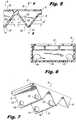
FIG. 2 ,fastener 10 generally includes anupper leg 26 and alower leg 28. In this embodiment,upper leg 26 andlower leg 28 are connected by a flexible, livinghinge 30. Livinghinge 30 allowsupper leg 26 andlower leg 28 to move between an open position substantially spaced apart to a closed position whereinupper leg 26 is substantially adjacent tolower leg 28.Upper leg 26 generally includes a base 32 having a row oftransverse teeth 34 extending lengthwise alongbase 32. Theteeth 34 are hollow so as to define a receptacle in each tooth.Upper leg 26 additionally includes a distal most tooth 36 (or differ slightly to incorporate a locking mechanism as described in more detail herein below).Base 32 includes a plurality ofbase openings 38 that communicate with a corresponding receptacle in a corresponding tooth, and distalmost tooth 36.Openings 38 are provided to receive materials to be dispensed to tissue as described in more detail herein below. Lower leg 28 also includes a base 40 having a row oftransverse teeth 42. Theteeth 42 are also hollow so as to define a receptacle in each tooth.Lower leg 28 also includes a distalmost tooth 44 onbase 40. It should be noted here in that, while the following specific descriptions of configurations, features and/or components oflegs legs legs Teeth 42 oflower leg 28 each include adistal face 46 andproximal face 48. Similarly, distalmost tooth 44 includes adistal face 50 and aproximal face 52. Pairs ofholes 54 are provided throughdistal face 46 andproximal face 48 ofhollow teeth 42. Livinghinge 30 is also provided with a pair ofholes 56 which are similar in size and spacing to holes 54. Additionally, in a particular embodiment, distalmost tooth 44 has a pair of spaced apart holes 58 inproximal face 52.Distal face 50 of distalmost tooth 44 as a pair of spaced apart holes 60 which can differ fromholes holes most tooth 36 inupper leg 26 may differ from the pairs of spaced apart holes inteeth 34 to form the disclosed locking mechanism.Upper leg 26 may be provided with alongitudinally extending membrane 62 which serves to coverbase openings 38 and secure materials withinhollow teeth - Referring for the moment to
FIG. 3 , there is disclosed an alternative, two-part toothed fastener 64 which is substantially identical totoothed fastener 10 except for the lack of a living hinge.Fastener 64 generally includes an upper leg 66 and alower leg 68. Upper leg 66 includes abase 70 and a row of transverse,hollow teeth 72. Upper leg 66 also includes a hollow distalmost tooth 74. Amembrane 76 is provided acrossbase 70 and functions similar tomembrane 62 described hereinabove. Similarly,lower leg 68 includes a base 78 having rows of transverse, longitudinally extendinghollow teeth 80 and a hollow distalmost tooth 82. Each ofhollow teeth 80 includes adistal face 84 and aproximal face 86. Hollow distalmost tooth 82 also includes aproximal face 88 and adistal face 90. A pair of spaced apart, holes 92 are provided indistal faces 84 and proximal faces 86 ofteeth 80. Likewise,proximal face 88 of distalmost tooth 82 includes a pair of spaced apart holes 94. In a specific embodiment,distal face 90 includes a pair of spaced apartdistal holes 96 which differ in size fromholes toothed fastener 10. As shown, upper leg 66 includes amembrane 76. As noted hereinabove, descriptions of the upper and lower legs of the various embodiments of the toothed fastener include similar components, such as the addition of a membrane tolower leg 68, except for variations in distalmost tooth 74 and distalmost tooth 82. Additionally, the operation oftoothed fastener 64, with the exception of a living hinge, functions the same as that described with respect totoothed fastener 10 hereinbelow. - Referring now to
FIG. 4 ,toothed fastener 10 also includes a securingmember 100 which serves several functions. Securingmember 100 has abacks pan 102 and a pair oflegs backspan 102.Legs distal tips member 100 is provided to secureupper leg 26 andlower leg 28 in the closed position. Specifically, in the closed position, holes provided inteeth upper leg 26 are in direct longitudinal alignment withholes lower leg 28. Thus, by driving securingmember 100, and specificallylegs holes 56 inbackspan 30 and throughholes lower leg 28 and the corresponding holes inupper leg 26,upper leg 26-.:is secured in the closed position relative tolower leg 28. Additionally, as-tips legs tips capsules 112 inupper leg 26 and capsules 114 (FIG. 4 ) inlower leg 28, to release materials contained therein onto tissue captured betweenupper leg 26 andlower leg 28.Capsules WO 2006/044800 may be used.Lower leg 28 is provided with amembrane 116 to securecapsules 114 withinhollow teeth tips distal face 50 of distalmost tooth 44, may act as a locking mechanism to preventstaple bar 100 from "backing out of'upper leg 26 andlower leg 28 as described below. Theleg 104 andleg 106 may be sized to functionally engage the interior surface of the fastener teeth insideholes 60, or theleg 104 and/orleg 106 have a textured surface for engaging inside theholes 60, or both. - Referring now to
FIGS. 5-7 , the details ofteeth upper leg 26 will now be described. As noted hereinabove,upper leg 26 includes adistal face 118 ofteeth 34 and proximal and distal faces, 120 and 122, respectively, ofteeth 36.Teeth 34 includeholes 124 which are similar in size toholes 54 inteeth 42 oflower leg 28. Similarly, distalmost tooth 36 includes a pair of spaced apart holes 126 formed inproximal face 120 which are also substantially the same as holes 54.Distal face 122 of distalmost tooth 36 includes a pair of spaced apart holes 128 which, together withtips member 100, may form a locking mechanism to securestaple bar 102 within upper andlower legs holes 128 indistal face 122 of distalmost tooth 36. Diameter d1 ofholes legs staple bar 100 so as to allow materials released fromcapsules upper leg 26 andlower leg 28 in the closed position. Diameter d2 of pair ofholes 128 may be sized so as to grasptips staple bar 100 in friction fit fashion thereby lockingstaple bar 100 in position withinupper leg 26 andlower leg 28. The teeth ofupper leg 26 define receptacles for a fluid material. Thelower leg 28 has teeth defihning receptacles and holes that are similar to those discussed above. - Referring now to
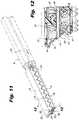
FIGS. 1 and8-12 , the use oftoothed fastener 10 inapplicator 12 will now be described. As shown inFIG. 1 ,toothed fastener 10 is attached tojaws applicator 12, such as, for example, by a snap-fit. Oncejaws FIG. 8 , this bringsupper leg 26 into close cooperative alignment withlower leg 28. In this position,teeth 34 ofupper leg 36 interengage or interdigitate withteeth 42 oflower leg 28. Depending upon the longitudinal orientation ofupper leg 26 relative tolower leg 28 withinupper jaw 18 andlower jaw 20, one of distalmost tooth 36 ofupper leg 26 or distalmost tooth 44 oflower leg 28 will become a distally most extending tooth oftoothed fastener 10. It should be noted that, depending upon which distalmost tooth member 100. Securingmember 100 is in a proximal most position within elongatetubular member 16.Applicator 12 is provided with apusher 130 positioned againstbackspan 102 of securingmember 100. - Referring now to
FIG. 9 , astrigger 22 is actuated,pusher 130urges securing member 100 distally within elongatetubular member 16. As securingmember 100 moves distally,tips legs holes 56 in livinghinge 30. Referring specifically toFIG. 10 , aslegs 104 and 106 (not shown) movesdistally tips holes 54 inteeth 42 oflower leg 28 andholes 124 ofteeth 34 ofupper leg 26. Aslegs holes tips legs capsules teeth toothed fastener 10 is capable of delivering material M to tissues captured betweenupper leg 26 andlower leg 28. Additionally, the passage oflegs holes upper leg 26 in the closed position relative tolower leg 28. - Referring now to
FIGS. 11 and 12 and initially with regard toFIG. 11 , aspusher 130advances securing member 100 completely throughupper leg 26 andlower leg 28,tips holes 128 indistal face 122 of distalmost tooth 36. As noted hereinabove, holes 128 may have a diameter d2 which is sufficiently small to engagetips member 100 is "locked" into position within upper orlower legs staple bar 100 from inadvertently pulling out of upper andlower legs tips holes 128 serves to sealholes 128 against any leakage of material M therethrough. - Referring to
FIG. 12 asleg 106 passes throughholes 126 inproximal face 120,capsule 112 is punctured and material and is released. As shown, when distalmost tooth 44 oflower leg 28 is not the distally most extending tooth oftooth fastener 10, holes 60 indistal face 50 are of the same diameter asholes 54 inproximal face 52 to allow passage of material M therethrough ascapsule 114 is penetrated. When the jaws of the surgical instrument are released from the tissue, through operation of theclamp handle 15, the toothed fastener is secured onto the tissue, as the securingmember 100 is retained in the teeth ofupper leg 26 and teeth oflower leg 28. Further, the material has been deployed to the tissue site. - It will be understood that various modifications may be made to the embodiments disclosed herein. For example, the teeth of the legs may be formed with a single hole in each of the proximal and distal faces for receipt of a single bar therthrough. Further, the tips of the staple bar may be enlarged to engage the distal most hole in rivet fashion. Additionally, the holes of the teeth may be covered be a penetratable membrane and the material provided as a fluid within the teeth. Therefore, the above description should not be construed as limiting, but merely as exemplifications of particular embodiments. Those skilled in the art will envision other modifications within the scope of the claims appended hereto.
Claims (13)
- A surgical fastener (10) comprising:an upper toothed leg (26) and a lower toothed leg (28), the upper toothed leg and the lower toothed leg each defining at least one tooth (42) having a proximal face (48) and a distal face (46) and defining a receptacle, wherein a hole (54) is formed in each of the proximal and distal faces;a securing member (100) receivable through the holes of the at least one tooth of the upper toothed leg and the lower toothed leg when all of the holes are in longitudinal alignment; anda fluid material (M) disposed in the receptacle of the at least one tooth of the upper toothed leg and the lower toothed leg,characterized in that each of the teeth are hollow and contain the fluid material such that passage of the securing member through the holes of the teeth releases the fluid material into the space between the upper and lower toothed legs.
- The surgical fastener (10) as recited in claim 1, wherein each tooth (42) has a pair of spaced apart holes (54) formed in each of the distal and proximal faces (46, 48).
- The surgical fastener (10) as recited in claim 2, wherein the securing member (100) is a staple bar having first and second legs (104, 106) for passage through the pair of spaced apart holes (54).
- The surgical fastener (10) as recited in claim 3, wherein the securing member (100) includes a backspan (102) and the first and second legs (104, 106) extend distally from the backspan.
- The surgical fastener (10) as recited in claim 1, wherein the hole (54) formed in each of the proximal and distal faces (48, 46) of each of the at least one tooth (42) is sized to engage the securing member (100) in friction fit fashion.
- The surgical fastener (10) as recited in any preceding claim, wherein the material (M) is contained within a puncturable capsule (112, 114).
- The surgical fastener (10) as recited in any preceding claim, further comprising a connector (30) connecting the upper toothed leg (26) to the lower toothed leg (28) at a proximal end.
- The surgical fastener (10) as recited in claim 7, wherein the connector (30) is a living hinge.
- The surgical fastener (10) as recited in claim 8, wherein the living hinge (30) is formed integrally with proximal ends of the upper toothed leg (26) and lower toothed leg (28).
- The surgical fastener (10) as recited in any preceding claim, wherein the upper toothed leg (26) has a plurality of teeth (34), the lower toothed leg (28) has a plurality of teeth (42), and the teeth of the upper toothed leg are configured to interengage with the teeth of the lower toothed leg.
- A surgical instrument (12), comprising a first jaw (18), a second jaw (20), a pusher (130), and the surgical fastener (10) as recited in claim 1, wherein the surgical fastener is positioned within the first and second jaws, and the pusher engages with the securing member (100) to advance the securing member through the upper toothed leg (26) and the lower toothed leg (28).
- The surgical fastener (10) as recited in any one of claims 1-10, wherein the upper toothed leg (26) is a first leg and the lower toothed leg (28) is a second leg.
- The surgical fastener (10) as recited in any one of claims 1-10, wherein the upper toothed leg (26) and the lower toothed leg (28) each has a base (32), each base having an opening (38) to the receptacle of the at least one tooth (42) of the upper toothed leg and the lower toothed leg respectively.
Applications Claiming Priority (3)
| Application Number | Priority Date | Filing Date | Title |
|---|---|---|---|
| US4982008P | 2008-05-02 | 2008-05-02 | |
| US12/427,792US8128642B2 (en) | 2008-05-02 | 2009-04-22 | Fluid delivery system for surgical instruments |
| EP09251238.3AEP2113209B1 (en) | 2008-05-02 | 2009-05-01 | Fluid delivery system for surgical instruments |
Related Parent Applications (2)
| Application Number | Title | Priority Date | Filing Date |
|---|---|---|---|
| EP09251238.3ADivisionEP2113209B1 (en) | 2008-05-02 | 2009-05-01 | Fluid delivery system for surgical instruments |
| EP09251238.3ADivision-IntoEP2113209B1 (en) | 2008-05-02 | 2009-05-01 | Fluid delivery system for surgical instruments |
Publications (2)
| Publication Number | Publication Date |
|---|---|
| EP3235452A1 EP3235452A1 (en) | 2017-10-25 |
| EP3235452B1true EP3235452B1 (en) | 2019-10-30 |
Family
ID=40940135
Family Applications (2)
| Application Number | Title | Priority Date | Filing Date |
|---|---|---|---|
| EP17169449.0AActiveEP3235452B1 (en) | 2008-05-02 | 2009-05-01 | Fluid delivery system for surgical instruments |
| EP09251238.3ANot-in-forceEP2113209B1 (en) | 2008-05-02 | 2009-05-01 | Fluid delivery system for surgical instruments |
Family Applications After (1)
| Application Number | Title | Priority Date | Filing Date |
|---|---|---|---|
| EP09251238.3ANot-in-forceEP2113209B1 (en) | 2008-05-02 | 2009-05-01 | Fluid delivery system for surgical instruments |
Country Status (6)
| Country | Link |
|---|---|
| US (2) | US8128642B2 (en) |
| EP (2) | EP3235452B1 (en) |
| JP (1) | JP5322104B2 (en) |
| AU (1) | AU2009201705B9 (en) |
| CA (1) | CA2664269C (en) |
| ES (1) | ES2635287T3 (en) |
Families Citing this family (79)
| Publication number | Priority date | Publication date | Assignee | Title |
|---|---|---|---|---|
| AU2003243219B2 (en) | 2003-05-09 | 2009-10-29 | Covidien Lp | Anastomotic staple with fluid dispensing capillary |
| US9060770B2 (en) | 2003-05-20 | 2015-06-23 | Ethicon Endo-Surgery, Inc. | Robotically-driven surgical instrument with E-beam driver |
| US9072535B2 (en) | 2011-05-27 | 2015-07-07 | Ethicon Endo-Surgery, Inc. | Surgical stapling instruments with rotatable staple deployment arrangements |
| US20120292367A1 (en) | 2006-01-31 | 2012-11-22 | Ethicon Endo-Surgery, Inc. | Robotically-controlled end effector |
| EP2015681B1 (en) | 2006-05-03 | 2018-03-28 | Datascope Corp. | Tissue closure device |
| US11980366B2 (en) | 2006-10-03 | 2024-05-14 | Cilag Gmbh International | Surgical instrument |
| US8632535B2 (en) | 2007-01-10 | 2014-01-21 | Ethicon Endo-Surgery, Inc. | Interlock and surgical instrument including same |
| US11564682B2 (en) | 2007-06-04 | 2023-01-31 | Cilag Gmbh International | Surgical stapler device |
| US8573465B2 (en) | 2008-02-14 | 2013-11-05 | Ethicon Endo-Surgery, Inc. | Robotically-controlled surgical end effector system with rotary actuated closure systems |
| US8636736B2 (en) | 2008-02-14 | 2014-01-28 | Ethicon Endo-Surgery, Inc. | Motorized surgical cutting and fastening instrument |
| US11986183B2 (en) | 2008-02-14 | 2024-05-21 | Cilag Gmbh International | Surgical cutting and fastening instrument comprising a plurality of sensors to measure an electrical parameter |
| US9585657B2 (en) | 2008-02-15 | 2017-03-07 | Ethicon Endo-Surgery, Llc | Actuator for releasing a layer of material from a surgical end effector |
| US8128642B2 (en)* | 2008-05-02 | 2012-03-06 | Tyco Healthcare Group Lp | Fluid delivery system for surgical instruments |
| US8652202B2 (en) | 2008-08-22 | 2014-02-18 | Edwards Lifesciences Corporation | Prosthetic heart valve and delivery apparatus |
| JP5388095B2 (en)* | 2008-09-30 | 2014-01-15 | 公益財団法人北九州産業学術推進機構 | Pinching device |
| US10517719B2 (en) | 2008-12-22 | 2019-12-31 | Valtech Cardio, Ltd. | Implantation of repair devices in the heart |
| US9968452B2 (en) | 2009-05-04 | 2018-05-15 | Valtech Cardio, Ltd. | Annuloplasty ring delivery cathethers |
| US8449599B2 (en) | 2009-12-04 | 2013-05-28 | Edwards Lifesciences Corporation | Prosthetic valve for replacing mitral valve |
| EP2511943A4 (en) | 2009-12-09 | 2015-09-09 | Asahi Glass Co Ltd | OPTICAL ELEMENT FOR EXTREME ULTRAVIOLET LITHOGRAPHY (EUV) |
| US8764778B2 (en)* | 2010-07-08 | 2014-07-01 | Sarkis Yeretsian | Biodegradable suture clip for joining bodily soft tissue |
| US12213666B2 (en)* | 2010-09-30 | 2025-02-04 | Cilag Gmbh International | Tissue thickness compensator comprising layers |
| US10945731B2 (en) | 2010-09-30 | 2021-03-16 | Ethicon Llc | Tissue thickness compensator comprising controlled release and expansion |
| US10335157B2 (en)* | 2010-10-02 | 2019-07-02 | Covidien Lp | Asymmetrical surgical clip with penetrating lock, non-slip clamping surface, severable hinge, hinge boss and pivoting applicator tip |
| EP3345573B1 (en) | 2011-06-23 | 2020-01-29 | Valtech Cardio, Ltd. | Closure element for use with annuloplasty structure |
| US20140001231A1 (en) | 2012-06-28 | 2014-01-02 | Ethicon Endo-Surgery, Inc. | Firing system lockout arrangements for surgical instruments |
| US9439763B2 (en) | 2013-02-04 | 2016-09-13 | Edwards Lifesciences Corporation | Prosthetic valve for replacing mitral valve |
| RU2672520C2 (en) | 2013-03-01 | 2018-11-15 | Этикон Эндо-Серджери, Инк. | Hingedly turnable surgical instruments with conducting ways for signal transfer |
| US9775609B2 (en) | 2013-08-23 | 2017-10-03 | Ethicon Llc | Tamper proof circuit for surgical instrument battery pack |
| WO2015077356A1 (en) | 2013-11-19 | 2015-05-28 | Wheeler William K | Fastener applicator with interlock |
| US9622863B2 (en) | 2013-11-22 | 2017-04-18 | Edwards Lifesciences Corporation | Aortic insufficiency repair device and method |
| US10105142B2 (en) | 2014-09-18 | 2018-10-23 | Ethicon Llc | Surgical stapler with plurality of cutting elements |
| US9924944B2 (en) | 2014-10-16 | 2018-03-27 | Ethicon Llc | Staple cartridge comprising an adjunct material |
| WO2016090308A1 (en) | 2014-12-04 | 2016-06-09 | Edwards Lifesciences Corporation | Percutaneous clip for repairing a heart valve |
| EP3294219B1 (en) | 2015-05-14 | 2020-05-13 | Edwards Lifesciences Corporation | Heart valve sealing devices and delivery devices therefor |
| US10799677B2 (en) | 2016-03-21 | 2020-10-13 | Edwards Lifesciences Corporation | Multi-direction steerable handles for steering catheters |
| US11219746B2 (en) | 2016-03-21 | 2022-01-11 | Edwards Lifesciences Corporation | Multi-direction steerable handles for steering catheters |
| US10835714B2 (en) | 2016-03-21 | 2020-11-17 | Edwards Lifesciences Corporation | Multi-direction steerable handles for steering catheters |
| US10799676B2 (en) | 2016-03-21 | 2020-10-13 | Edwards Lifesciences Corporation | Multi-direction steerable handles for steering catheters |
| US10799675B2 (en) | 2016-03-21 | 2020-10-13 | Edwards Lifesciences Corporation | Cam controlled multi-direction steerable handles |
| US10973638B2 (en) | 2016-07-07 | 2021-04-13 | Edwards Lifesciences Corporation | Device and method for treating vascular insufficiency |
| EP3498177B1 (en)* | 2016-08-08 | 2023-08-23 | Touchstone International Medical Science Co., Ltd. | Tissue closing device and medical instrument |
| US10653862B2 (en) | 2016-11-07 | 2020-05-19 | Edwards Lifesciences Corporation | Apparatus for the introduction and manipulation of multiple telescoping catheters |
| US10973516B2 (en) | 2016-12-21 | 2021-04-13 | Ethicon Llc | Surgical end effectors and adaptable firing members therefor |
| US10905554B2 (en) | 2017-01-05 | 2021-02-02 | Edwards Lifesciences Corporation | Heart valve coaptation device |
| EP4613214A2 (en) | 2017-04-18 | 2025-09-10 | Edwards Lifesciences Corporation | Heart valve sealing devices and delivery devices therefor |
| US11224511B2 (en) | 2017-04-18 | 2022-01-18 | Edwards Lifesciences Corporation | Heart valve sealing devices and delivery devices therefor |
| US10799312B2 (en) | 2017-04-28 | 2020-10-13 | Edwards Lifesciences Corporation | Medical device stabilizing apparatus and method of use |
| US10959846B2 (en) | 2017-05-10 | 2021-03-30 | Edwards Lifesciences Corporation | Mitral valve spacer device |
| US11051940B2 (en) | 2017-09-07 | 2021-07-06 | Edwards Lifesciences Corporation | Prosthetic spacer device for heart valve |
| US11065117B2 (en) | 2017-09-08 | 2021-07-20 | Edwards Lifesciences Corporation | Axisymmetric adjustable device for treating mitral regurgitation |
| US11040174B2 (en) | 2017-09-19 | 2021-06-22 | Edwards Lifesciences Corporation | Multi-direction steerable handles for steering catheters |
| US10842490B2 (en) | 2017-10-31 | 2020-11-24 | Ethicon Llc | Cartridge body design with force reduction based on firing completion |
| US10973639B2 (en) | 2018-01-09 | 2021-04-13 | Edwards Lifesciences Corporation | Native valve repair devices and procedures |
| US10231837B1 (en) | 2018-01-09 | 2019-03-19 | Edwards Lifesciences Corporation | Native valve repair devices and procedures |
| US10245144B1 (en) | 2018-01-09 | 2019-04-02 | Edwards Lifesciences Corporation | Native valve repair devices and procedures |
| US10238493B1 (en) | 2018-01-09 | 2019-03-26 | Edwards Lifesciences Corporation | Native valve repair devices and procedures |
| US10123873B1 (en) | 2018-01-09 | 2018-11-13 | Edwards Lifesciences Corporation | Native valve repair devices and procedures |
| US10076415B1 (en) | 2018-01-09 | 2018-09-18 | Edwards Lifesciences Corporation | Native valve repair devices and procedures |
| FI3964175T3 (en) | 2018-01-09 | 2024-12-03 | Edwards Lifesciences Corp | Native valve repair devices |
| US10159570B1 (en) | 2018-01-09 | 2018-12-25 | Edwards Lifesciences Corporation | Native valve repair devices and procedures |
| US10507109B2 (en) | 2018-01-09 | 2019-12-17 | Edwards Lifesciences Corporation | Native valve repair devices and procedures |
| US10111751B1 (en) | 2018-01-09 | 2018-10-30 | Edwards Lifesciences Corporation | Native valve repair devices and procedures |
| US10136993B1 (en) | 2018-01-09 | 2018-11-27 | Edwards Lifesciences Corporation | Native valve repair devices and procedures |
| US10105222B1 (en) | 2018-01-09 | 2018-10-23 | Edwards Lifesciences Corporation | Native valve repair devices and procedures |
| JP7348199B2 (en) | 2018-03-28 | 2023-09-20 | データスコープ コーポレイション | Device for atrial appendage exclusion |
| US11389297B2 (en) | 2018-04-12 | 2022-07-19 | Edwards Lifesciences Corporation | Mitral valve spacer device |
| US11207181B2 (en) | 2018-04-18 | 2021-12-28 | Edwards Lifesciences Corporation | Heart valve sealing devices and delivery devices therefor |
| US10945844B2 (en) | 2018-10-10 | 2021-03-16 | Edwards Lifesciences Corporation | Heart valve sealing devices and delivery devices therefor |
| CN113226223A (en) | 2018-11-20 | 2021-08-06 | 爱德华兹生命科学公司 | Deployment tools and methods for delivering devices to native heart valves |
| CA3118988A1 (en) | 2018-11-21 | 2020-05-28 | Edwards Lifesciences Corporation | Heart valve sealing devices, delivery devices therefor, and retrieval devices |
| CR20210312A (en) | 2018-11-29 | 2021-09-14 | Edwards Lifesciences Corp | Catheterization method and apparatus |
| ES2969252T3 (en) | 2019-02-14 | 2024-05-17 | Edwards Lifesciences Corp | Heart valve sealing devices and delivery devices therefor |
| CA3173298A1 (en)* | 2020-02-27 | 2021-09-02 | Altyx Surgical Inc. | Tissue surface piercing systems and methods |
| US20210322002A1 (en)* | 2020-04-16 | 2021-10-21 | Covidien Lp | Surgical instrument for performing a purse string suture |
| US11324500B2 (en)* | 2020-06-30 | 2022-05-10 | Covidien Lp | Surgical stapling device |
| US11666337B2 (en)* | 2020-07-08 | 2023-06-06 | Covidien Lp | Purse string suture instrument |
| US20220183681A1 (en)* | 2020-12-15 | 2022-06-16 | Covidien Lp | Purse string suture passer device |
| US11723658B2 (en) | 2021-03-22 | 2023-08-15 | Cilag Gmbh International | Staple cartridge comprising a firing lockout |
| USD1071198S1 (en) | 2023-06-28 | 2025-04-15 | Edwards Lifesciences Corporation | Cradle |
Family Cites Families (23)
| Publication number | Priority date | Publication date | Assignee | Title |
|---|---|---|---|---|
| US565698A (en)* | 1896-08-11 | Half to j | ||
| US1982207A (en)* | 1933-12-29 | 1934-11-27 | Henry D Furniss | Clamping instrument and process of using the same |
| US3757387A (en)* | 1971-12-17 | 1973-09-11 | Continental Oil Co | Apparatus for securing small diameter conduit to a larger diameter tubing string or the like |
| US4345600A (en)* | 1980-08-04 | 1982-08-24 | Senco Products, Inc. | Purse-stringer |
| US4394864A (en)* | 1981-04-15 | 1983-07-26 | Jeffrey Sandhaus | Apparatus and method for effecting occlusion of the vas deferens |
| US4412370A (en)* | 1981-06-19 | 1983-11-01 | Speirs Graeme K | Clamps |
| FR2632833A1 (en)* | 1988-06-16 | 1989-12-22 | Lyon Michel | Device for partially curling the hair |
| US5411481A (en)* | 1992-04-08 | 1995-05-02 | American Cyanamid Co. | Surgical purse string suturing instrument and method |
| ES2122282T3 (en) | 1993-04-30 | 1998-12-16 | United States Surgical Corp | SURGICAL INSTRUMENT THAT HAS AN ARTICULATED JAW STRUCTURE. |
| EP0699418A1 (en) | 1994-08-05 | 1996-03-06 | United States Surgical Corporation | Self-contained powered surgical apparatus |
| US5584856A (en)* | 1994-12-21 | 1996-12-17 | Jameel; Irfan M. | Removable surgical staple |
| AU697045B2 (en) | 1995-01-16 | 1998-09-24 | Baxter International Inc. | Self-supporting sheet-like material of cross-linked fibrin for preventing post- operative adhesions |
| US5843126A (en)* | 1997-08-15 | 1998-12-01 | Jameel; Irfan M. | Multiple surgical suture application |
| US6488197B1 (en) | 2000-02-22 | 2002-12-03 | Power Medical Interventions, Inc. | Fluid delivery device for use with anastomosing resecting and stapling instruments |
| US6869436B2 (en)* | 2002-02-07 | 2005-03-22 | Scimed Life Systems, Inc. | Surgical clip with a self-releasing fluid reservoir |
| JP4316491B2 (en) | 2002-05-10 | 2009-08-19 | タイコ ヘルスケア グループ エルピー | Wound closure material applicator and stapler |
| EP1572009A2 (en) | 2002-12-17 | 2005-09-14 | Applied Medical Resources Corporation | Surgical staple-clip and applier |
| US7922743B2 (en) | 2004-10-18 | 2011-04-12 | Tyco Healthcare Group Lp | Structure for applying sprayable wound treatment material |
| US20070078414A1 (en)* | 2005-08-05 | 2007-04-05 | Mcallister Devin V | Methods and devices for delivering agents across biological barriers |
| US20080039879A1 (en) | 2006-08-09 | 2008-02-14 | Chin Albert K | Devices and methods for atrial appendage exclusion |
| US7780685B2 (en)* | 2006-11-09 | 2010-08-24 | Ethicon Endo-Surgery, Inc. | Adhesive and mechanical fastener |
| US8678263B2 (en) | 2007-09-24 | 2014-03-25 | Covidien Lp | Materials delivery system for stapling device |
| US8128642B2 (en)* | 2008-05-02 | 2012-03-06 | Tyco Healthcare Group Lp | Fluid delivery system for surgical instruments |
- 2009
- 2009-04-22USUS12/427,792patent/US8128642B2/ennot_activeExpired - Fee Related
- 2009-04-27CACA2664269Apatent/CA2664269C/ennot_activeExpired - Fee Related
- 2009-04-29AUAU2009201705Apatent/AU2009201705B9/ennot_activeCeased
- 2009-05-01EPEP17169449.0Apatent/EP3235452B1/enactiveActive
- 2009-05-01ESES09251238.3Tpatent/ES2635287T3/enactiveActive
- 2009-05-01JPJP2009112357Apatent/JP5322104B2/ennot_activeExpired - Fee Related
- 2009-05-01EPEP09251238.3Apatent/EP2113209B1/ennot_activeNot-in-force
- 2012
- 2012-02-02USUS13/364,428patent/US8900256B2/ennot_activeExpired - Fee Related
Non-Patent Citations (1)
| Title |
|---|
| None* |
Also Published As
| Publication number | Publication date |
|---|---|
| EP2113209A1 (en) | 2009-11-04 |
| US8128642B2 (en) | 2012-03-06 |
| JP2009279401A (en) | 2009-12-03 |
| US20120130402A1 (en) | 2012-05-24 |
| EP3235452A1 (en) | 2017-10-25 |
| EP2113209B1 (en) | 2017-07-05 |
| ES2635287T3 (en) | 2017-10-03 |
| US20090275902A1 (en) | 2009-11-05 |
| US8900256B2 (en) | 2014-12-02 |
| AU2009201705B9 (en) | 2013-11-28 |
| AU2009201705A1 (en) | 2009-11-19 |
| AU2009201705B2 (en) | 2013-08-01 |
| CA2664269A1 (en) | 2009-11-02 |
| JP5322104B2 (en) | 2013-10-23 |
| CA2664269C (en) | 2017-07-04 |
Similar Documents
| Publication | Publication Date | Title |
|---|---|---|
| EP3235452B1 (en) | Fluid delivery system for surgical instruments | |
| JP6411584B2 (en) | Surgical instrument with filled staples | |
| JP6208134B2 (en) | Surgical instrument with staple reinforcing clip | |
| JP6133299B2 (en) | Surgical instruments and buttress materials | |
| JP5649218B2 (en) | Suture and retainer assembly and SULU | |
| JP6203729B2 (en) | Surgical instrument having a buttress capable of being filled with fluid | |
| CN110366390A (en) | Appendices Release for Surgical Staplers | |
| EP2343016A1 (en) | Surgical stapling apparatus with clamping assembly | |
| EP1782740A1 (en) | Surgical instruments structured for delivery of medical agents | |
| CA2685717A1 (en) | Variable size-uniform compression staple assembly | |
| CN115397341A (en) | System and device for treating tissue | |
| CN110520064A (en) | System for the appendicular release in surgical stapling device | |
| AU2013206351B2 (en) | Fluid delivery system for surgical instruments | |
| US20080188875A1 (en) | Bloodless and painless surgical method |
Legal Events
| Date | Code | Title | Description |
|---|---|---|---|
| PUAI | Public reference made under article 153(3) epc to a published international application that has entered the european phase | Free format text:ORIGINAL CODE: 0009012 | |
| STAA | Information on the status of an ep patent application or granted ep patent | Free format text:STATUS: THE APPLICATION HAS BEEN PUBLISHED | |
| AC | Divisional application: reference to earlier application | Ref document number:2113209 Country of ref document:EP Kind code of ref document:P | |
| AK | Designated contracting states | Kind code of ref document:A1 Designated state(s):AT BE BG CH CY CZ DE DK EE ES FI FR GB GR HR HU IE IS IT LI LT LU LV MC MK MT NL NO PL PT RO SE SI SK TR | |
| STAA | Information on the status of an ep patent application or granted ep patent | Free format text:STATUS: REQUEST FOR EXAMINATION WAS MADE | |
| 17P | Request for examination filed | Effective date:20180418 | |
| RBV | Designated contracting states (corrected) | Designated state(s):AT BE BG CH CY CZ DE DK EE ES FI FR GB GR HR HU IE IS IT LI LT LU LV MC MK MT NL NO PL PT RO SE SI SK TR | |
| STAA | Information on the status of an ep patent application or granted ep patent | Free format text:STATUS: EXAMINATION IS IN PROGRESS | |
| 17Q | First examination report despatched | Effective date:20181112 | |
| GRAP | Despatch of communication of intention to grant a patent | Free format text:ORIGINAL CODE: EPIDOSNIGR1 | |
| STAA | Information on the status of an ep patent application or granted ep patent | Free format text:STATUS: GRANT OF PATENT IS INTENDED | |
| INTG | Intention to grant announced | Effective date:20190603 | |
| GRAS | Grant fee paid | Free format text:ORIGINAL CODE: EPIDOSNIGR3 | |
| GRAA | (expected) grant | Free format text:ORIGINAL CODE: 0009210 | |
| STAA | Information on the status of an ep patent application or granted ep patent | Free format text:STATUS: THE PATENT HAS BEEN GRANTED | |
| AC | Divisional application: reference to earlier application | Ref document number:2113209 Country of ref document:EP Kind code of ref document:P | |
| AK | Designated contracting states | Kind code of ref document:B1 Designated state(s):AT BE BG CH CY CZ DE DK EE ES FI FR GB GR HR HU IE IS IT LI LT LU LV MC MK MT NL NO PL PT RO SE SI SK TR | |
| REG | Reference to a national code | Ref country code:GB Ref legal event code:FG4D | |
| REG | Reference to a national code | Ref country code:CH Ref legal event code:EP | |
| REG | Reference to a national code | Ref country code:DE Ref legal event code:R096 Ref document number:602009060331 Country of ref document:DE | |
| REG | Reference to a national code | Ref country code:AT Ref legal event code:REF Ref document number:1195320 Country of ref document:AT Kind code of ref document:T Effective date:20191115 | |
| REG | Reference to a national code | Ref country code:IE Ref legal event code:FG4D | |
| REG | Reference to a national code | Ref country code:LT Ref legal event code:MG4D | |
| PG25 | Lapsed in a contracting state [announced via postgrant information from national office to epo] | Ref country code:PT Free format text:LAPSE BECAUSE OF FAILURE TO SUBMIT A TRANSLATION OF THE DESCRIPTION OR TO PAY THE FEE WITHIN THE PRESCRIBED TIME-LIMIT Effective date:20200302 Ref country code:FI Free format text:LAPSE BECAUSE OF FAILURE TO SUBMIT A TRANSLATION OF THE DESCRIPTION OR TO PAY THE FEE WITHIN THE PRESCRIBED TIME-LIMIT Effective date:20191030 Ref country code:BG Free format text:LAPSE BECAUSE OF FAILURE TO SUBMIT A TRANSLATION OF THE DESCRIPTION OR TO PAY THE FEE WITHIN THE PRESCRIBED TIME-LIMIT Effective date:20200130 Ref country code:NL Free format text:LAPSE BECAUSE OF FAILURE TO SUBMIT A TRANSLATION OF THE DESCRIPTION OR TO PAY THE FEE WITHIN THE PRESCRIBED TIME-LIMIT Effective date:20191030 Ref country code:LV Free format text:LAPSE BECAUSE OF FAILURE TO SUBMIT A TRANSLATION OF THE DESCRIPTION OR TO PAY THE FEE WITHIN THE PRESCRIBED TIME-LIMIT Effective date:20191030 Ref country code:SE Free format text:LAPSE BECAUSE OF FAILURE TO SUBMIT A TRANSLATION OF THE DESCRIPTION OR TO PAY THE FEE WITHIN THE PRESCRIBED TIME-LIMIT Effective date:20191030 Ref country code:PL Free format text:LAPSE BECAUSE OF FAILURE TO SUBMIT A TRANSLATION OF THE DESCRIPTION OR TO PAY THE FEE WITHIN THE PRESCRIBED TIME-LIMIT Effective date:20191030 Ref country code:NO Free format text:LAPSE BECAUSE OF FAILURE TO SUBMIT A TRANSLATION OF THE DESCRIPTION OR TO PAY THE FEE WITHIN THE PRESCRIBED TIME-LIMIT Effective date:20200130 Ref country code:GR Free format text:LAPSE BECAUSE OF FAILURE TO SUBMIT A TRANSLATION OF THE DESCRIPTION OR TO PAY THE FEE WITHIN THE PRESCRIBED TIME-LIMIT Effective date:20200131 Ref country code:LT Free format text:LAPSE BECAUSE OF FAILURE TO SUBMIT A TRANSLATION OF THE DESCRIPTION OR TO PAY THE FEE WITHIN THE PRESCRIBED TIME-LIMIT Effective date:20191030 | |
| REG | Reference to a national code | Ref country code:NL Ref legal event code:MP Effective date:20191030 | |
| PG25 | Lapsed in a contracting state [announced via postgrant information from national office to epo] | Ref country code:HR Free format text:LAPSE BECAUSE OF FAILURE TO SUBMIT A TRANSLATION OF THE DESCRIPTION OR TO PAY THE FEE WITHIN THE PRESCRIBED TIME-LIMIT Effective date:20191030 Ref country code:IS Free format text:LAPSE BECAUSE OF FAILURE TO SUBMIT A TRANSLATION OF THE DESCRIPTION OR TO PAY THE FEE WITHIN THE PRESCRIBED TIME-LIMIT Effective date:20200229 | |
| PG25 | Lapsed in a contracting state [announced via postgrant information from national office to epo] | Ref country code:EE Free format text:LAPSE BECAUSE OF FAILURE TO SUBMIT A TRANSLATION OF THE DESCRIPTION OR TO PAY THE FEE WITHIN THE PRESCRIBED TIME-LIMIT Effective date:20191030 Ref country code:DK Free format text:LAPSE BECAUSE OF FAILURE TO SUBMIT A TRANSLATION OF THE DESCRIPTION OR TO PAY THE FEE WITHIN THE PRESCRIBED TIME-LIMIT Effective date:20191030 Ref country code:ES Free format text:LAPSE BECAUSE OF FAILURE TO SUBMIT A TRANSLATION OF THE DESCRIPTION OR TO PAY THE FEE WITHIN THE PRESCRIBED TIME-LIMIT Effective date:20191030 Ref country code:RO Free format text:LAPSE BECAUSE OF FAILURE TO SUBMIT A TRANSLATION OF THE DESCRIPTION OR TO PAY THE FEE WITHIN THE PRESCRIBED TIME-LIMIT Effective date:20191030 Ref country code:CZ Free format text:LAPSE BECAUSE OF FAILURE TO SUBMIT A TRANSLATION OF THE DESCRIPTION OR TO PAY THE FEE WITHIN THE PRESCRIBED TIME-LIMIT Effective date:20191030 | |
| PGFP | Annual fee paid to national office [announced via postgrant information from national office to epo] | Ref country code:FR Payment date:20200422 Year of fee payment:12 Ref country code:DE Payment date:20200421 Year of fee payment:12 | |
| REG | Reference to a national code | Ref country code:DE Ref legal event code:R097 Ref document number:602009060331 Country of ref document:DE | |
| REG | Reference to a national code | Ref country code:AT Ref legal event code:MK05 Ref document number:1195320 Country of ref document:AT Kind code of ref document:T Effective date:20191030 | |
| PG25 | Lapsed in a contracting state [announced via postgrant information from national office to epo] | Ref country code:SK Free format text:LAPSE BECAUSE OF FAILURE TO SUBMIT A TRANSLATION OF THE DESCRIPTION OR TO PAY THE FEE WITHIN THE PRESCRIBED TIME-LIMIT Effective date:20191030 | |
| PGFP | Annual fee paid to national office [announced via postgrant information from national office to epo] | Ref country code:IT Payment date:20200421 Year of fee payment:12 Ref country code:GB Payment date:20200423 Year of fee payment:12 | |
| PLBE | No opposition filed within time limit | Free format text:ORIGINAL CODE: 0009261 | |
| STAA | Information on the status of an ep patent application or granted ep patent | Free format text:STATUS: NO OPPOSITION FILED WITHIN TIME LIMIT | |
| 26N | No opposition filed | Effective date:20200731 | |
| PG25 | Lapsed in a contracting state [announced via postgrant information from national office to epo] | Ref country code:AT Free format text:LAPSE BECAUSE OF FAILURE TO SUBMIT A TRANSLATION OF THE DESCRIPTION OR TO PAY THE FEE WITHIN THE PRESCRIBED TIME-LIMIT Effective date:20191030 Ref country code:SI Free format text:LAPSE BECAUSE OF FAILURE TO SUBMIT A TRANSLATION OF THE DESCRIPTION OR TO PAY THE FEE WITHIN THE PRESCRIBED TIME-LIMIT Effective date:20191030 | |
| PG25 | Lapsed in a contracting state [announced via postgrant information from national office to epo] | Ref country code:LI Free format text:LAPSE BECAUSE OF NON-PAYMENT OF DUE FEES Effective date:20200531 Ref country code:CH Free format text:LAPSE BECAUSE OF NON-PAYMENT OF DUE FEES Effective date:20200531 Ref country code:MC Free format text:LAPSE BECAUSE OF FAILURE TO SUBMIT A TRANSLATION OF THE DESCRIPTION OR TO PAY THE FEE WITHIN THE PRESCRIBED TIME-LIMIT Effective date:20191030 | |
| REG | Reference to a national code | Ref country code:BE Ref legal event code:MM Effective date:20200531 | |
| PG25 | Lapsed in a contracting state [announced via postgrant information from national office to epo] | Ref country code:LU Free format text:LAPSE BECAUSE OF NON-PAYMENT OF DUE FEES Effective date:20200501 | |
| PG25 | Lapsed in a contracting state [announced via postgrant information from national office to epo] | Ref country code:IE Free format text:LAPSE BECAUSE OF NON-PAYMENT OF DUE FEES Effective date:20200501 | |
| PG25 | Lapsed in a contracting state [announced via postgrant information from national office to epo] | Ref country code:BE Free format text:LAPSE BECAUSE OF NON-PAYMENT OF DUE FEES Effective date:20200531 | |
| REG | Reference to a national code | Ref country code:DE Ref legal event code:R119 Ref document number:602009060331 Country of ref document:DE | |
| GBPC | Gb: european patent ceased through non-payment of renewal fee | Effective date:20210501 | |
| PG25 | Lapsed in a contracting state [announced via postgrant information from national office to epo] | Ref country code:GB Free format text:LAPSE BECAUSE OF NON-PAYMENT OF DUE FEES Effective date:20210501 Ref country code:DE Free format text:LAPSE BECAUSE OF NON-PAYMENT OF DUE FEES Effective date:20211201 | |
| PG25 | Lapsed in a contracting state [announced via postgrant information from national office to epo] | Ref country code:TR Free format text:LAPSE BECAUSE OF FAILURE TO SUBMIT A TRANSLATION OF THE DESCRIPTION OR TO PAY THE FEE WITHIN THE PRESCRIBED TIME-LIMIT Effective date:20191030 Ref country code:MT Free format text:LAPSE BECAUSE OF FAILURE TO SUBMIT A TRANSLATION OF THE DESCRIPTION OR TO PAY THE FEE WITHIN THE PRESCRIBED TIME-LIMIT Effective date:20191030 Ref country code:FR Free format text:LAPSE BECAUSE OF NON-PAYMENT OF DUE FEES Effective date:20210531 Ref country code:CY Free format text:LAPSE BECAUSE OF FAILURE TO SUBMIT A TRANSLATION OF THE DESCRIPTION OR TO PAY THE FEE WITHIN THE PRESCRIBED TIME-LIMIT Effective date:20191030 | |
| PG25 | Lapsed in a contracting state [announced via postgrant information from national office to epo] | Ref country code:MK Free format text:LAPSE BECAUSE OF FAILURE TO SUBMIT A TRANSLATION OF THE DESCRIPTION OR TO PAY THE FEE WITHIN THE PRESCRIBED TIME-LIMIT Effective date:20191030 | |
| PG25 | Lapsed in a contracting state [announced via postgrant information from national office to epo] | Ref country code:IT Free format text:LAPSE BECAUSE OF NON-PAYMENT OF DUE FEES Effective date:20200501 | |
| PG25 | Lapsed in a contracting state [announced via postgrant information from national office to epo] | Ref country code:IT Free format text:LAPSE BECAUSE OF NON-PAYMENT OF DUE FEES Effective date:20210501 |