EP3235241B1 - System for processing video images generated by a multiple viewing elements endoscope - Google Patents
System for processing video images generated by a multiple viewing elements endoscopeDownload PDFInfo
- Publication number
- EP3235241B1 EP3235241B1EP15870783.6AEP15870783AEP3235241B1EP 3235241 B1EP3235241 B1EP 3235241B1EP 15870783 AEP15870783 AEP 15870783AEP 3235241 B1EP3235241 B1EP 3235241B1
- Authority
- EP
- European Patent Office
- Prior art keywords
- weight
- endoscope
- digital gain
- brightness
- luminance
- Prior art date
- Legal status (The legal status is an assumption and is not a legal conclusion. Google has not performed a legal analysis and makes no representation as to the accuracy of the status listed.)
- Active
Links
Images


Classifications
- A—HUMAN NECESSITIES
- A61—MEDICAL OR VETERINARY SCIENCE; HYGIENE
- A61B—DIAGNOSIS; SURGERY; IDENTIFICATION
- A61B1/00—Instruments for performing medical examinations of the interior of cavities or tubes of the body by visual or photographical inspection, e.g. endoscopes; Illuminating arrangements therefor
- A61B1/00002—Operational features of endoscopes
- A61B1/00004—Operational features of endoscopes characterised by electronic signal processing
- A61B1/00009—Operational features of endoscopes characterised by electronic signal processing of image signals during a use of endoscope
- A—HUMAN NECESSITIES
- A61—MEDICAL OR VETERINARY SCIENCE; HYGIENE
- A61B—DIAGNOSIS; SURGERY; IDENTIFICATION
- A61B1/00—Instruments for performing medical examinations of the interior of cavities or tubes of the body by visual or photographical inspection, e.g. endoscopes; Illuminating arrangements therefor
- A61B1/00163—Optical arrangements
- A61B1/00174—Optical arrangements characterised by the viewing angles
- A61B1/00177—Optical arrangements characterised by the viewing angles for 90 degrees side-viewing
- A—HUMAN NECESSITIES
- A61—MEDICAL OR VETERINARY SCIENCE; HYGIENE
- A61B—DIAGNOSIS; SURGERY; IDENTIFICATION
- A61B1/00—Instruments for performing medical examinations of the interior of cavities or tubes of the body by visual or photographical inspection, e.g. endoscopes; Illuminating arrangements therefor
- A61B1/00163—Optical arrangements
- A61B1/00174—Optical arrangements characterised by the viewing angles
- A61B1/00181—Optical arrangements characterised by the viewing angles for multiple fixed viewing angles
- A—HUMAN NECESSITIES
- A61—MEDICAL OR VETERINARY SCIENCE; HYGIENE
- A61B—DIAGNOSIS; SURGERY; IDENTIFICATION
- A61B1/00—Instruments for performing medical examinations of the interior of cavities or tubes of the body by visual or photographical inspection, e.g. endoscopes; Illuminating arrangements therefor
- A61B1/04—Instruments for performing medical examinations of the interior of cavities or tubes of the body by visual or photographical inspection, e.g. endoscopes; Illuminating arrangements therefor combined with photographic or television appliances
- A61B1/042—Instruments for performing medical examinations of the interior of cavities or tubes of the body by visual or photographical inspection, e.g. endoscopes; Illuminating arrangements therefor combined with photographic or television appliances characterised by a proximal camera, e.g. a CCD camera
- A—HUMAN NECESSITIES
- A61—MEDICAL OR VETERINARY SCIENCE; HYGIENE
- A61B—DIAGNOSIS; SURGERY; IDENTIFICATION
- A61B1/00—Instruments for performing medical examinations of the interior of cavities or tubes of the body by visual or photographical inspection, e.g. endoscopes; Illuminating arrangements therefor
- A61B1/04—Instruments for performing medical examinations of the interior of cavities or tubes of the body by visual or photographical inspection, e.g. endoscopes; Illuminating arrangements therefor combined with photographic or television appliances
- A61B1/045—Control thereof
- A—HUMAN NECESSITIES
- A61—MEDICAL OR VETERINARY SCIENCE; HYGIENE
- A61B—DIAGNOSIS; SURGERY; IDENTIFICATION
- A61B1/00—Instruments for performing medical examinations of the interior of cavities or tubes of the body by visual or photographical inspection, e.g. endoscopes; Illuminating arrangements therefor
- A61B1/04—Instruments for performing medical examinations of the interior of cavities or tubes of the body by visual or photographical inspection, e.g. endoscopes; Illuminating arrangements therefor combined with photographic or television appliances
- A61B1/05—Instruments for performing medical examinations of the interior of cavities or tubes of the body by visual or photographical inspection, e.g. endoscopes; Illuminating arrangements therefor combined with photographic or television appliances characterised by the image sensor, e.g. camera, being in the distal end portion
- H—ELECTRICITY
- H04—ELECTRIC COMMUNICATION TECHNIQUE
- H04N—PICTORIAL COMMUNICATION, e.g. TELEVISION
- H04N23/00—Cameras or camera modules comprising electronic image sensors; Control thereof
- H04N23/50—Constructional details
- H04N23/555—Constructional details for picking-up images in sites, inaccessible due to their dimensions or hazardous conditions, e.g. endoscopes or borescopes
- H—ELECTRICITY
- H04—ELECTRIC COMMUNICATION TECHNIQUE
- H04N—PICTORIAL COMMUNICATION, e.g. TELEVISION
- H04N23/00—Cameras or camera modules comprising electronic image sensors; Control thereof
- H04N23/70—Circuitry for compensating brightness variation in the scene
- H04N23/71—Circuitry for evaluating the brightness variation
- H—ELECTRICITY
- H04—ELECTRIC COMMUNICATION TECHNIQUE
- H04N—PICTORIAL COMMUNICATION, e.g. TELEVISION
- H04N23/00—Cameras or camera modules comprising electronic image sensors; Control thereof
- H04N23/70—Circuitry for compensating brightness variation in the scene
- H04N23/76—Circuitry for compensating brightness variation in the scene by influencing the image signals
- H—ELECTRICITY
- H04—ELECTRIC COMMUNICATION TECHNIQUE
- H04N—PICTORIAL COMMUNICATION, e.g. TELEVISION
- H04N25/00—Circuitry of solid-state image sensors [SSIS]; Control thereof
- H04N25/50—Control of the SSIS exposure
- H04N25/57—Control of the dynamic range
- H04N25/58—Control of the dynamic range involving two or more exposures
- H—ELECTRICITY
- H04—ELECTRIC COMMUNICATION TECHNIQUE
- H04N—PICTORIAL COMMUNICATION, e.g. TELEVISION
- H04N25/00—Circuitry of solid-state image sensors [SSIS]; Control thereof
- H04N25/60—Noise processing, e.g. detecting, correcting, reducing or removing noise
- H04N25/61—Noise processing, e.g. detecting, correcting, reducing or removing noise the noise originating only from the lens unit, e.g. flare, shading, vignetting or "cos4"
- H04N25/611—Correction of chromatic aberration
- H—ELECTRICITY
- H04—ELECTRIC COMMUNICATION TECHNIQUE
- H04N—PICTORIAL COMMUNICATION, e.g. TELEVISION
- H04N25/00—Circuitry of solid-state image sensors [SSIS]; Control thereof
- H04N25/60—Noise processing, e.g. detecting, correcting, reducing or removing noise
- H04N25/62—Detection or reduction of noise due to excess charges produced by the exposure, e.g. smear, blooming, ghost image, crosstalk or leakage between pixels
- H04N25/621—Detection or reduction of noise due to excess charges produced by the exposure, e.g. smear, blooming, ghost image, crosstalk or leakage between pixels for the control of blooming
- H—ELECTRICITY
- H04—ELECTRIC COMMUNICATION TECHNIQUE
- H04N—PICTORIAL COMMUNICATION, e.g. TELEVISION
- H04N25/00—Circuitry of solid-state image sensors [SSIS]; Control thereof
- H04N25/70—SSIS architectures; Circuits associated therewith
- H04N25/71—Charge-coupled device [CCD] sensors; Charge-transfer registers specially adapted for CCD sensors
- H—ELECTRICITY
- H04—ELECTRIC COMMUNICATION TECHNIQUE
- H04N—PICTORIAL COMMUNICATION, e.g. TELEVISION
- H04N25/00—Circuitry of solid-state image sensors [SSIS]; Control thereof
- H04N25/70—SSIS architectures; Circuits associated therewith
- H04N25/76—Addressed sensors, e.g. MOS or CMOS sensors
Definitions
- the present specificationgenerally relates to a multiple viewing elements endoscope, and more particularly to controlling bloomed or saturated areas of video images generated by the viewing elements of the endoscope.
- Endoscopessuch as colonoscopes, that are currently being used, typically have multiple viewing elements, such as cameras, that correspondingly include Charge Coupled Device (CCD) or CMOS image sensors to generate video feeds.
- CCDCharge Coupled Device
- CMOS image sensorsare fraught with problems, such as saturation and blooming, that affect both their quantitative and qualitative imaging characteristics. For example, if each individual pixel can be thought of as a well of electrons, then saturation refers to the condition where the well becomes filled. The amount of charge that can be accumulated in a single pixel is determined largely by its area. However, due to the nature of the potential well, which holds charge within a pixel, there is less probability of trapping an electron within a well that is approaching saturation. Therefore, as a well approaches its limit, the linear relationship between light intensity and signal degrades. As a result, the apparent responsivity of a saturated pixel drops.
- US 2014/184916 A1discloses a method and system for real time luminance correction and detail enhancement of a video image. The method includes the steps of extracting a luminance component from a video image then separating the luminance component into an illumination layer and a scene reflectivity layer.
- the illumination layerhas a dynamic range. Then the dynamic range of the illumination layer is compressed to generate a corrected illumination layer. Filtering the reflectivity layer then generates an enhanced reflectivity layer. Combining the corrected illumination layer with the enhanced scene reflectivity layer generates an enhanced luminance image.
- the inventionis defined in claim 1.
- the present specificationdiscloses an endoscope video processing system for controlling blooming in an image frame of a video data signal generated by a viewing element of an endoscope, to facilitate an increased luminance digital gain in regions of a first brightness within the image frame while maintaining a decreased luminance digital gain in regions of a second brightness, wherein the first brightness is lower than the second brightness
- said video processing systemcomprising: a processor; a memory; a digital signal processor for applying a reduced digital gain to a luminance (Y) component of the video data signal to generate an attenuated signal, wherein the reduced digital gain is defined by a weight; and a local blooming control module for: calculating an average luminance value of luminance levels of a plurality of pixels neighboring a pixel of the attenuated signal; operating a function on the average luminance value to generate a smoothly transitioning digital gain; conditioning the smoothly transitioning digital gain using said weight to generate a customizable digital gain; and applying the customizable digital gain to the attenuated signal.
- said weightcomprises a first weight and a second weight.
- the reduced digital gainmeets a condition where a sum of the first weight and the second weight is in the range of 1.0 to 5.0.
- the first weightis a constant value while the second weight has a value depending on surrounding luminance.
- the average luminance valueis calculated using Gaussian weights.
- the functionis a sigmoid function. Still optionally, a center point of the sigmoid function approximates 240/(1 + second weight), wherein said viewing element of the endoscope comprises a CCD sensor. Still optionally, a center point of the sigmoid function approximates 255/(1 + second weight), wherein said viewing element of the endoscope comprises a CMOS sensor. Still optionally, a center point of the sigmoid function approximates 100/(1 + second weight), wherein said viewing element of the endoscope comprises a CMOS sensor. According to the invention, a center point of the sigmoid function decreases as the second weight increases and said center point increases as the second weight decreases.
- the customizable digital gainmay meet a plurality of conditions, wherein said plurality of conditions may include at least one of: a value of said digital gain approaches 1.0 as a brightness of a region of the image frame nears maximal value; said digital gain has an upper limit of 5.0 in a region of the image frame that, relative to all other regions in said image frame, is darkest; or said digital gain transitions from a region of a first brightness to a region of a second brightness, wherein the first brightness is greater than the second brightness, in a smooth manner.
- the present specificationdiscloses a method of controlling blooming in a plurality of regions of an image frame of a video data signal generated by a viewing element of an endoscope, said method being implemented by the controller of the endoscope, the method comprising: attenuating a luminance (Y) component of the video data signal to generate an attenuated signal, wherein the attenuation factor meets a condition such that a summation of a first weight K 1 and a second weight K 2 approximates a value equal to or less than 5.0; applying a Gaussian function to luminance levels of a plurality of pixels neighboring a given pixel of the attenuated signal to generate an average luminance signal Gaussian(Y); applying a sigmoid function to the average luminance signal to generate a modified signal sigmoid(Gaussian(Y)); and applying a digital gain to the attenuated signal, wherein the digital gain is determined by applying weights to the modified signal sigmoid (G
- the weightscomprise a first weight K 1 and a second weight K 2 , wherein K 1 is a constant value and K 2 has a value depending on surrounding luminance.
- a center point of the sigmoid functionapproximates 240/(1 + K 2 ), wherein said viewing element of the endoscope comprises a CCD sensor.
- a center point of the sigmoid functionapproximates 255/(1 + second weight), wherein said viewing element of the endoscope comprises a CMOS sensor.
- a center point of the sigmoid functionapproximates 100/(1 + second weight), wherein said viewing element of the endoscope comprises a CMOS sensor.
- a center point of the sigmoid functiondecreases as the second weight K 2 increases and said center point increases as the second weight K 2 decreases.
- the value of said digital gainapproaches 1.0 as brightness of a region of the image frame nears maximum value.
- the value of said digital gainhas an upper limit of 5.0 in a region of the image frame that, relative to all other regions in an image frame, is the darkest.
- said digital gaintransitions from a region of a first brightness to a region of a second brightness, wherein the first brightness is greater than the second brightness, in a smooth manner.
- the present specificationis directed toward an endoscope video processing system for controlling blooming in an image frame of a video data signal generated by a viewing element of an endoscope, to facilitate an increased luminance digital gain in regions of a first brightness within the image frame while maintaining a decreased luminance digital gain in regions of a second brightness, wherein the first brightness is lower than the second brightness
- said video processing systemcomprising a processor and memory for executing the steps of: applying a reduced digital gain to a luminance (Y) component of the video data signal to generate an attenuated signal, wherein the reduced digital gain is defined by a weight; calculating an average luminance value of luminance levels of a plurality of pixels neighboring a pixel of the attenuated signal; operating a function on the average luminance value to generate a smoothly transitioning digital gain; conditioning the smoothly transitioning digital gain using said weight to generate a customizable digital gain; and applying the customizable digital gain to the attenuated signal.
- endoscopemay refer particularly to a colonoscope and a gastroscope, according to some embodiments, but is not limited only to colonoscopies and/or gastroscopies.
- endoscopemay refer to any instrument used to examine the interior of a hollow organ or cavity of the body.
- Figure 1shows an exploded view of a tip section 200 of a multi-viewing element endoscope assembly 100 comprising a front working/service channel, according to various embodiments.
- An aspect of some embodimentsalso relates to endoscope assembly 100 having the tip section 200 that may be equipped with one or more side working/service channels.
- tip section 200 of the endoscope 100may include a tip cover 300, an electronic circuit board assembly 400 and a fluid channeling component 600.
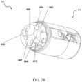
- Figures 2A and 2Bshow perspective views of the tip section 200 according to an embodiment.
- the tip section 200includes a front panel 320 which comprises four quadrants defined by a vertical axis passing through a center of the front panel 320 and a horizontal axis passing through the center, wherein the four quadrants include a top left quadrant, a top right quadrant, a bottom left quadrant and a bottom right quadrant.
- a transparent surface, window, or opening to front optical lens assembly 256(of front looking camera or viewing element 116) is positioned on the front panel 320.
- a first front optical window 242bfor a first front illuminator 240b, is positioned on the front panel 320, at least partially within the bottom right quadrant and at least partially within the bottom left quadrant.
- a second front optical window 242afor a second front illuminator 240a, is positioned on the front panel 320, at least partially within the bottom left quadrant.
- a third front optical window 242cfor a third front illuminator 240c, is positioned on the front panel 320, at least partially within the bottom right quadrant.
- a front working channel opening 340for working channel 640, is positioned on the front panel 320, along the vertical axis and at least partially within the top left quadrant and partially within the top right quadrant.
- a fluid injector opening 346for a fluid injector channel 646, is positioned on the front panel 320, at least partially within the top right quadrant.
- a jet channel opening 344for a jet channel 644, is positioned on the front panel 320, at least partially within the top left quadrant.
- fluid channeling component 600may include a proximal fluid channeling section 602 (or base) which may have an essentially cylindrical shape and a unitary distal channeling section 604 (or elongated housing).
- Distal fluid channeling section 604may partially continue the cylindrical shape of proximal fluid channeling section 602 and may have a shape of a partial cylinder (optionally elongated partial cylinder).
- Distal fluid channeling section 604may have only a fraction of the cylinder (along the height or length axis of the cylinder), wherein another fraction of the cylinder (along the height or length axis of the cylinder) is missing.
- proximal fluid channeling section 602has a greater width than distal fluid channeling section 604.
- Distal fluid channeling section 604may be integrally formed as a unitary block with proximal fluid channeling section 602.
- the height or length of distal fluid channeling section 604may by higher or longer than the height or length of proximal fluid channeling section 602.
- the shape of the partial cylinder(for example, partial cylinder having only a fraction of a cylindrical shape along one side of the height axis) may provide a space to accommodate electronic circuit board assembly 400.
- Distal fluid channeling section 604includes working channel 640, which may be configured for insertion of a surgical tool, for example, to remove, treat and/or extract a sample of the object of interest found in the colon or its entirety for biopsy.
- Distal fluid channeling section 604further includes the jet fluid channel 644 which may be configured for providing a high pressure jet of fluid, such as water or saline, for cleaning the walls of the body cavity (such as the colon) and optionally for suction.
- Distal fluid channeling section 604further includes injector channel 646, which may be used for injecting fluid (liquid and/or gas) to wash contaminants such as blood, feces and other debris from a surface of front optical lens assembly 256 of forward-looking viewing element 116.
- Proximal fluid channeling section 602 of fluid channeling component 600also includes side injector channel 666, which connects to side injector opening 266, and side injector channel 667 which connects to a similar side injector opening positioned on the opposite side of the tip section 200.
- the proximal fluid channeling section 602also includes a groove 670 is adapted to guide (and optionally hold in place) an electric cable(s) which may be connected at its distal end to the electronic components such as viewing elements (for example, cameras) and/or light sources in the endoscope's tip section and deliver electrical power and/or command signals to the tip section and/or transmit video signal from the cameras to be displayed to the user.
- Electronic circuit board assembly 400may be configured to carry a front looking viewing element 116, a first side looking viewing element and a second side viewing element 116b which may be similar to front looking viewing element 116 and may include a Charge Coupled Device (CCD) or a Complementary Metal Oxide Semiconductor (CMOS) image sensor.
- the electronic circuit board assembly 400may be configured to carry front illuminators 240a, 240b, 240c, which may be associated with front looking viewing element 116 and may be positioned to essentially illuminate the field of view of front looking viewing element 116.
- electronic circuit board assembly 400may be configured to carry side illuminators 250a and 250b, which may be associated with side looking viewing element 116b and may be positioned to essentially illuminate side looking viewing element's 116b field of view.
- Electronic circuit board assembly 400may also be configured to carry side illuminators, which may be associated with the opposite side looking viewing element, which may be similar to side illuminators 250a and 250b.
- Front illuminators 240a, 240b, 240c and side illuminators 250a and 250bmay optionally be discrete illuminators and may include a light-emitting diode (LED), which may be a white light LED, an infrared light LED, a near infrared light LED, an ultraviolet light LED or any other LED.
- LEDlight-emitting diode
- discretemay refer to an illumination source, which generates light internally, in contrast to a non-discrete illuminator, which may be, for example, a fiber optic merely transmitting light generated remotely.
- Tip cover 300may be configured to fit over the inner parts of the tip section 200 including electronic circuit board assembly 400 and fluid channeling component 600 and to provide protection to the internal components in the inner parts.
- Front optical lens assembly 256may include a plurality of lenses, static or movable, which may provide a field of view of 90 degrees or more, 120 degrees or more or up to essentially 180 degrees. Front optical lens assembly 256 may provide a focal length in the range of about 3 to 100 millimeters.
- An optical axis of front looking camera or viewing element 116may be essentially directed along the long dimension of the endoscope. However, since front looking camera or viewing element 116 is typically a wide angle camera, its field of view may include viewing directions at large angles to its optical axis.
- depression 364Visible on the sidewall 362 of tip cover 300 is depression 364 wherein placed within depression 364 is side optical lens assembly 256b for side looking camera or viewing element 116b, which may be similar to front optical lens assembly 256, and optical windows 252a and 252b of illuminators 250a and 250b for side looking camera or viewing element 116b.
- side optical lens assembly 256bfor side looking camera or viewing element 116b, which may be similar to front optical lens assembly 256, and optical windows 252a and 252b of illuminators 250a and 250b for side looking camera or viewing element 116b.
- the side optical lens assemblies 256b, 256cmay
- An optical axis of the first side viewing element 116bmay be essentially directed perpendicular to the long dimension of the endoscope.
- An optical axis of the second side viewing elementmay be essentially directed perpendicular to the long dimension of the endoscope.
- each side viewing elementtypically comprises a wide angle camera, its field of view may include viewing directions at large angles to its optical axis.
- each side viewing elementhas a field of view of 90 degrees or more, 120 degrees or more or up to essentially 180 degrees.
- side injector opening 266 of side injector channel 666may be located at a proximal end of sidewall 362 and side injector opening 269 of side injector 667 may be located at a proximal end of sidewall 363.
- a nozzle cover 267may be configured to fit side injector opening 266 and a similar nozzle cover (not shown) may be configured to fit side injector opening 269.
- nozzle cover 267may include a nozzle 268 which may be aimed at side optical lens assembly 256b and configured for injecting fluid to wash contaminants such as blood, feces and other debris from a surface of side optical lens assembly 256b of side looking camera or viewing element 116b.
- the fluidmay include gas which may be used for inflating a body cavity.
- nozzle 268may be configured for cleaning both side optical lens assembly 256b and optical windows 252a and/or 252b.
- tip section 200is presented herein showing one side thereof, the opposing side may include elements similar to the side elements described herein (for example, side looking camera, side optical lens assembly, injector(s), nozzle(s), illuminator(s), window(s), opening(s) and other elements).
- System 300may include a multi-viewing elements endoscope 302.
- Multi-viewing elements endoscope 302may include a handle 304, from which an elongated shaft 306 emerges. Elongated shaft 306 terminates with a tip section 308 which is turnable by way of a bending section 310.
- Handle 304may be used for maneuvering elongated shaft 306 within a body cavity.
- the handlemay include one or more buttons and/or knobs and/or switches 305 which control bending section 310 as well as functions such as fluid injection and suction.
- Handle 304may further include at least one, and in some embodiments, one or more working channel openings 312 through which surgical tools may be inserted as well as one and more side service channel openings.
- a utility cable 314, also referred to as an umbilical tube,may connect between handle 304 and a Main Control Unit 399.
- Utility cable 314may include therein one or more fluid channels and one or more electrical channels.
- the electrical channel(s)may include at least one data cable for receiving video signals from the front and side-pointing viewing elements, as well as at least one power cable for providing electrical power to the viewing elements and to the discrete illuminators.
- the main control unit 399contains the controls required for displaying the images of internal organs captured by the endoscope 302.
- the main control unit 399may govern power transmission to the endoscope's 302 tip section 308, such as for the tip section's viewing elements and illuminators.
- the main control unit 399may further control one or more fluid, liquid and/or suction pump(s) which supply corresponding functionalities to the endoscope 302.
- One or more input devices 318, such as a keyboard, a touch screen and the likemay be connected to the main control unit 399 for the purpose of human interaction with the main control unit 399.
- the main control unit 399comprises a screen/display 325 for displaying operation information concerning an endoscopy procedure when the endoscope 302 is in use.
- the screen 325may be configured to display images and/or video streams received from the viewing elements of the multi-viewing element endoscope 302.
- the screen 325may further be operative to display a user interface for allowing a human operator to set various features of the endoscopy system.
- the video streams received from the different viewing elements of the multi-viewing element endoscope 302may be displayed separately on at least one monitor (not seen) by uploading information from the main control unit 399, either side-by-side or interchangeably (namely, the operator may switch between views from the different viewing elements manually).
- these video streamsmay be processed by the main control unit 399 to combine them into a single, panoramic video frame, based on an overlap between fields of view of the viewing elements.
- two or more displaysmay be connected to the main control unit 399, each for displaying a video stream from a different viewing element of the multi-viewing element endoscope 302.
- the main control unit 399is described in United States Patent Application Number 14/263,896 , which, for priority, relies on United States Provisional Patent Application Number 61/817,237, entitled “Method and System for Video Processing in a Multi-Viewing Element Endoscope” and filed on April 29, 2013 ,
- FIG 4details how the video controller or the controller circuit board 420 of the main control unit 399 of Figure 3 operatively connects with the endoscope 410 and the display units 450, according to one embodiment.
- video controller/controller circuit board 420comprises a camera board 421 that controls the power supplies to the LEDs 411, transmits controls for the operation of image sensor(s) 412 (comprising one or more cameras) in the endoscope, and converts pre-video signals from image sensors to standard video signals.
- the image sensor 412may be a charge coupled device (CCD) or a complementary metal oxide semiconductor (CMOS) imager.
- the camera board 421receives pre-video signal(s) 413 generated by the CCD imager and also other remote commands 414 from the endoscope 410.
- Controller circuit board 420further comprises elements for processing the video obtained from the image sensors 412 through the camera board 421, as well as other elements for system monitoring and control.
- Base Board Module 452which is a PCB.
- elements which are ICs (Integrated Circuits)are connected by soldering
- element 426SOM or System on Module
- mountingwhile all other elements are connected by means of cables.
- Base Board Module 452Various elements on the Base Board Module 452 are described as follows:
- FPGA 423is a logic device programmed specifically for the system requirements and performs tasks that may be categorized by two types: logic tasks which must be implemented by hardware (as opposed to software), and logic tasks related to video image processing.
- the Base Board Module 452includes one or more double data rate type three synchronous dynamic random access memory modules (DDR3) 433 in communication with the FPGA 423.
- DDR3synchronous dynamic random access memory modules
- Logic taskswhich are preferably implemented by hardware include, but are not limited to:
- Logic tasks related to video image processinginclude, but are not limited to:
- DSP 422is used for recording compressed (coded) video and playing back decompressed (decoded) video.
- the standard of compressed videois H264 or equivalent (such as MPEG).
- FPGA 423selects for the DSP 422 the desired video to be recorded, i.e. any of the inputs, or, more likely, a copy of one or more of the screens. In the latter case, this includes the OSD and format conversion. In the likely case of the screen's format differing from that of DSP's 422 required video input format, the FPGA 423 also converts the screen's format to the desired DSP 422 format while transmitting video to the DSP 422.
- the video input to the Auxiliary Video Input Interface 425may comprise analog video, such as in CVBS (color, video, blanking, sync), S-Video or YPbPr format or digital video (DVI), and may be displayed as such.
- CVBScolor, video, blanking, sync
- S-VideoS-Video
- YPbPr formatdigital video
- the SOM 426provides an interface to input devices such as keyboard, mouse, and touchscreen via Touch I/F 427. Through these input devices, together with the buttons 440 in the Front Panel 435, the user controls the system's functionality and operational parameters.
- a peripheral component interconnect express (PCIe) busconnects the SOM 426 with the FPGA 423. Most common types of data traffic over the PCIe are:
- the controller circuit board 420may further control one or more fluid, liquid and/or suction pump(s) which supply corresponding functionalities to the endoscope through pneumatic I/F 428, pump 429 and check valve 430.
- the controller circuit board 420further comprises an on-board power supply 445 and a front panel 435 which provides operational buttons 440 for the user.
- FIG 5Ais another illustration of the video controller or the controller circuit board 500 of the main control unit 399 of Figure 3 .
- the camera board 520receives video signals which, in one embodiment, comprises three video feeds, corresponding to video feed pickups by three endoscopic tip viewing elements (one front and two side-looking viewing elements), as generated by the image sensor 412 ( Figure 4 ).
- the video feed pickupsare separated into three different video feeds/data streams 505, 510, and 515 for processing by respective Digital Signal Processors (DSPs) 506, 511 and 516.
- DSPsDigital Signal Processors
- the video data streams 507, 512 and 517(corresponding to the three viewing elements) output from the DSPs 506, 511, 516 respectively comprise a luminance component (Y), a blue-difference (C B ) chroma component, and a red-difference (C R ) chroma component.
- Yluminance component
- C Bblue-difference
- C Rred-difference
- the three video feed/data streams 507, 512 and 517, corresponding to the three viewing elements (the front-looking, left-side looking and rightside looking viewing elements) of an endoscopic tip 501 (such as the three viewing elements of the tip section 200 of Figure 1 ),are processed by the FPGA 525, encoded (for example, serialization of video data into HDMI/DVI serial lines) using encoders 530 and thereafter displayed on three respective monitors 535, 540 and 545.
- the FPGA 525performs a plurality of logic tasks related to video stream/image processing - one of which includes brightness and/or blooming control.
- the DSPs 506, 511, 516apply a reduced gain on the luminance (Y) components of the video data streams 505, 510, 515 so that the corresponding output video data streams 507, 512, 517 meet an anti-blooming condition/constraint.
- the anti-blooming condition, constraint, or restrictionis that a respective Y component is not saturated even when the corresponding image is very bright.
- the Y component valueremains lower than 255 (since, Y, C B and C R are each 8-bit) by a safe margin so that image details are perceivable to a viewer.
- the DSPs 506, 511, 516the Y (luminance) components of the three video data streams 505, 510, 515 are attenuated by a factor of: K 1 + K 2 ⁇ 1.5 , where K 1 represents an element of the gain which is constant, not depending on surrounding luminance, and K 2 represents a weight attributed to the surrounding luminance.
- K 1is 1.00 and K 1 + K 2 ⁇ 1.5.
- K 1 + K 2equals a range of 1.0 to 5.0.
- a less preferred solution to this dimming effectcan be to have the FPGA 525 add a digital gain to the Y component, wherein the gain may vary every image frame according to the total average brightness of that frame. However, this would still cause blooming in image frames where there are only small portions of very high luminance, thereby having very little effect on the average brightness. Conversely, in bright image frames with small dark portions, the dimming effect may still persist - with possible loss in image details.
- a local blooming control (LBC) moduleis implemented to facilitate a higher luminance digital gain in darker portions while maintaining a low or no luminance digital gain in brighter portions, within the same image frame.
- the LBC moduleimplements the following processing steps and conditions:
- averaging of luminance levels of neighboring pixelsis done with Gaussian weighing.
- This average luminance levelfeeds a sigmoid function, an example of which is illustrated in Figure 6 .
- K 1represents an element of the gain which is constant, and independent of the surrounding luminance. In one embodiment, it is 1.00.
- FIG. 5Bis a block diagram illustrating implementation of a local blooming control (LBC) module 550 within the FPGA 525, in accordance with various embodiments of the present specification.
- LBClocal blooming control
- the LBC module 550can be implemented either as firmware (FPGA) or software executing in a general processor. In the former case, the parameters affecting the LBC operation may be either hard-coded to spare firmware resources or programmable to enable flexibility.
- a video feed/data streamsuch as stream 507 output from the camera board 520, arrives as input stream to the FPGA 525.
- the Y (luminance) component 507 Y of the input data stream 507is fed into a dual 2D (two dimensional) programmable and transparent FIR (Finite Impulse Response) filter 555 to apply a Gaussian function around the Y component 507 Y , as described above, resulting in an output Gaussian (Y) signal 507 G .
- a dual 2D (two dimensional) programmable and transparent FIR (Finite Impulse Response) filter 555to apply a Gaussian function around the Y component 507 Y , as described above, resulting in an output Gaussian (Y) signal 507 G .
- the 2D FIR filter 555comprises a pipeline of programmable (or hard-coded) coefficients 556 for Gaussian calculation.
- the size of the 2D FIR filter 555 chosendepends at least on a combination of and optimization between: a) available FPGA resources such as memory cells and arithmetic modules and b) the required size of the image frame region over which luminance average is calculated.
- the 2D FIR filter 555 sizecomprises 9V x 15H (9 lines by 15 pixels) which is the reason why Figure 5B illustrates the Y component 507 Y being fed through a shared 9 tap vertical pipeline 552 while the programmable coefficients 556 include weighted vertical summation for a 15 tap horizontal pipeline 554.
- the maximum size of the 2D FIR filteris in the range of 30V x 30H.
- the 2D FIR filter 555is of the type which is both separable and symmetric.
- a separable 2D-FIR filteris implementable as two separate 1D-FIR filters, one for the vertical axis and the other for the horizontal axis.
- alternate embodimentsmay utilize other types of 2D-FIR filters such as, for example, a non-separable filter.
- Dual 2D-FIR filterprovides for a future use of the secondary 2D-FIR such as, for example, for implementing an image sharpening function.
- the Dual 2D-FIR filteris replaced with a single modified 2D-FIR filter that outputs the central pixel of its matrix as-is, in addition to the Gaussian.
- the output Gaussian(Y) signal 507 Gforms an input to a plurality of ROM-based LUTs (Look-Up Tables) 560 (to implement a sigmoid function on signal 507 G ) driving a programmable multiplexer 565.
- ROM-based LUTsLook-Up Tables
- a four ROM-based LUT system 560is used for implementing the sigmoid function.
- alternate embodimentshave ROMs more or less than four.
- a single programmable RAM-based LUT(Look-Up Table) is implemented that is programmable (by software/firmware) in real-time for any sigmoid type.
- the multiplexer 565outputs a sigmoid (Gaussian(Y)) signal 507 SG .
- the sigmoid functionis so selected such that its center point approximates 240/(1 + K 2 ), that is - the center point moves towards the left (decreases) as K 2 increases, and vice versa.
- the value "240"depends on the type of image sensor being used. For example, in case of CCD sensors, 240 represents the upper limit for Y (luminance) component of the YCbCr color space. For CMOS sensors, other color spaces, such as LAB may be used, which require a different value as the maximum limit of the luminance component.
- the value chosen as maximum limit of luminance component in case of CMOS sensorsis either 100 or 255.
- the chosen value of maximum limitis hardwired to a register.
- the value of maximum limitis added to the FPGA logic and the system software, such that it can be altered depending upon the type of image sensor used.
- the sigmoid functionis selected such that its center point approximates X/(1+Kz) where X is indicative of a Y component of a color space specific to a type of image sensor being used.
- a pipeline 557 of coefficients and delay component 558participates in delaying the original Y component 507 Y so that when it reaches the mixer 570, it is aligned with the sigmoid (Gaussian(Y)) signal 507 SG .
- the original Y component 507 Y and the sigmoid (Gaussian(Y)) signal 507 SGare aligned when they reach the mixer 570.
- the mixer 570is programmable, in accordance with an embodiment, with weights K 1 and K 2 so as to apply a gain K 1 + K 2 x sigmoid (Gaussian) on the Y component 507 Y and output a blooming controlled Y component 507 YLCB .
- the C B and C R Chroma components 507 CB , 507 CR of the input data stream 507are respectively fed into a first and a second dual 2D (two dimensional) transparent FIR (Finite Impulse Response) filter 575, 580.
- transparent FIR filterssuch as FIR filters 575, 580
- coefficientsare degenerated, that is all coefficients are null, except for the central one which is unity.
- FIR outputis identical to its input, but with the addition of a delay.
- the filters 575, 580 and the respective delay components 576, 581apply latency to the C B and C R components 507 CB and 507 CR , to align them with the signal 507 SG . It should be appreciated, however, that delaying of the C B and C R components 507 CB and 507 CR is required only if they share the same synchronization signals with the Y component 507 Y .
- a first LBC module 550applies a managed luminance gain to the video feed/data stream 507, as described above.
- additional LBC modules(such as for example module 590), are implemented to manage application of luminance gain to the corresponding additional video feed/data streams 512, 517 ( Figure 5A ).
- the number of LBC modulesdepends upon the number of video feeds/data streams and therefore the number of viewing elements of the endoscopic tip.
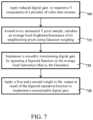
- FIG. 7is a flow chart illustrating a plurality of exemplary steps of a brightness, luminance or blooming control method in accordance with an embodiment of the present specification.
- a reduced digital gain or attenuationis applied to respective Y (luminance) components of a plurality of video data streams (such as for example three video data streams generated by a multi-viewing elements endoscope) to output respective Y-attenuated output video streams.
- the Y componentsare attenuated by a factor of K 1 + K 2 ⁇ 1.5 so that the Y components are not saturated even when the corresponding images are very bright.
- the attenuated video data streams, output as a result of step 705,are respectively processed to facilitate a higher luminance digital gain in darker portions while maintaining a low or no luminance digital gain in brighter portions, within the same image frame.
- an average local brightness/luminance of its neighboring pixelsis calculated.
- the averagingis done using Gaussian weights.
- the output Gaussian of the neighboring pixelsis utilized to develop/implement a smoothly transitioning digital gain at step 725, such that areas of higher Gaussians are assigned higher digital gains than areas of lower Gaussians.
- a transitionis smooth if it has continuous derivatives up to some order over the domain of values. The number of continuous derivatives necessary for a function to be considered smooth is two or greater.
- a smoothly transitioning gainis defined as a gain that transitions from bright areas to dark areas in a smooth manner.
- the smoothly transitioning digital gainis implemented by operating a sigmoid function on the output Gaussian of step 715.
- the sigmoid functionis further weighed or conditioned to apply a customizable digital gain.
- the customizable digital gain appliedmeets the following conditions:
- the customizable digital gainis calculated as K 1 + K 2 x sigmoid (Gaussian(Y)), where K 1 and K 2 are a first and a second weights operating on an output/result of the sigmoid function/operation.
- K 1represents an element of the gain which is constant and independent of the surrounding luminance.
- K 1is 1.00 in one embodiment.
- K 2represents a weight attributed to the surrounding luminance.
- each of the words “comprise” “include” and “have”, and forms thereof,are not necessarily limited to members in a list with which the words may be associated.
Landscapes
- Life Sciences & Earth Sciences (AREA)
- Health & Medical Sciences (AREA)
- Engineering & Computer Science (AREA)
- Surgery (AREA)
- Signal Processing (AREA)
- Radiology & Medical Imaging (AREA)
- Medical Informatics (AREA)
- Nuclear Medicine, Radiotherapy & Molecular Imaging (AREA)
- Optics & Photonics (AREA)
- Pathology (AREA)
- Physics & Mathematics (AREA)
- Veterinary Medicine (AREA)
- Biomedical Technology (AREA)
- Heart & Thoracic Surgery (AREA)
- Biophysics (AREA)
- Molecular Biology (AREA)
- Animal Behavior & Ethology (AREA)
- General Health & Medical Sciences (AREA)
- Public Health (AREA)
- Multimedia (AREA)
- Endoscopes (AREA)
- Instruments For Viewing The Inside Of Hollow Bodies (AREA)
- Computer Vision & Pattern Recognition (AREA)
Description
- The present specification generally relates to a multiple viewing elements endoscope, and more particularly to controlling bloomed or saturated areas of video images generated by the viewing elements of the endoscope.
- Endoscopes, such as colonoscopes, that are currently being used, typically have multiple viewing elements, such as cameras, that correspondingly include Charge Coupled Device (CCD) or CMOS image sensors to generate video feeds. CCD as well as CMOS image sensors are fraught with problems, such as saturation and blooming, that affect both their quantitative and qualitative imaging characteristics. For example, if each individual pixel can be thought of as a well of electrons, then saturation refers to the condition where the well becomes filled. The amount of charge that can be accumulated in a single pixel is determined largely by its area. However, due to the nature of the potential well, which holds charge within a pixel, there is less probability of trapping an electron within a well that is approaching saturation. Therefore, as a well approaches its limit, the linear relationship between light intensity and signal degrades. As a result, the apparent responsivity of a saturated pixel drops.
- At saturation, pixels lose their ability to accommodate additional charge. This additional charge then spreads into neighboring pixels, causing them to either report erroneous values or also saturate. This spread of charge to adjacent pixels is known as blooming and appears as a white streak or blob in the image. The occurrence of blooming, in video images generated by a multi-viewing elements endoscope, results in loss of details in portions of the video image and is a serious cause of concern for a physician performing an endoscopic procedure.
US 2014/184916 A1 discloses a method and system for real time luminance correction and detail enhancement of a video image. The method includes the steps of extracting a luminance component from a video image then separating the luminance component into an illumination layer and a scene reflectivity layer. The illumination layer has a dynamic range. Then the dynamic range of the illumination layer is compressed to generate a corrected illumination layer. Filtering the reflectivity layer then generates an enhanced reflectivity layer. Combining the corrected illumination layer with the enhanced scene reflectivity layer generates an enhanced luminance image. - Accordingly, there is need in the art for processing the video feeds generated by a plurality of viewing elements of an endoscopic tip such that saturation is minimized and/or the occurrence of blooming is effectively controlled in the video feeds.
- The following embodiments and aspects thereof are described and illustrated in conjunction with systems, tools and methods, which are meant to be exemplary and illustrative, not limiting in scope.
- The invention is defined in claim 1.
- The present specification discloses an endoscope video processing system for controlling blooming in an image frame of a video data signal generated by a viewing element of an endoscope, to facilitate an increased luminance digital gain in regions of a first brightness within the image frame while maintaining a decreased luminance digital gain in regions of a second brightness, wherein the first brightness is lower than the second brightness, said video processing system comprising: a processor; a memory; a digital signal processor for applying a reduced digital gain to a luminance (Y) component of the video data signal to generate an attenuated signal, wherein the reduced digital gain is defined by a weight; and a local blooming control module for: calculating an average luminance value of luminance levels of a plurality of pixels neighboring a pixel of the attenuated signal; operating a function on the average luminance value to generate a smoothly transitioning digital gain; conditioning the smoothly transitioning digital gain using said weight to generate a customizable digital gain; and applying the customizable digital gain to the attenuated signal.
- According to the invention, said weight comprises a first weight and a second weight. Still optionally, the reduced digital gain meets a condition where a sum of the first weight and the second weight is in the range of 1.0 to 5.0. Still optionally, the first weight is a constant value while the second weight has a value depending on surrounding luminance.
- Optionally, the average luminance value is calculated using Gaussian weights.
- According to the invention, the function is a sigmoid function. Still optionally, a center point of the sigmoid function approximates 240/(1 + second weight), wherein said viewing element of the endoscope comprises a CCD sensor. Still optionally, a center point of the sigmoid function approximates 255/(1 + second weight), wherein said viewing element of the endoscope comprises a CMOS sensor. Still optionally, a center point of the sigmoid function approximates 100/(1 + second weight), wherein said viewing element of the endoscope comprises a CMOS sensor. According to the invention, a center point of the sigmoid function decreases as the second weight increases and said center point increases as the second weight decreases.
- In some embodiments, the customizable digital gain may meet a plurality of conditions, wherein said plurality of conditions may include at least one of: a value of said digital gain approaches 1.0 as a brightness of a region of the image frame nears maximal value; said digital gain has an upper limit of 5.0 in a region of the image frame that, relative to all other regions in said image frame, is darkest; or said digital gain transitions from a region of a first brightness to a region of a second brightness, wherein the first brightness is greater than the second brightness, in a smooth manner.
- In some embodiments not forming part of the invention, the present specification discloses a method of controlling blooming in a plurality of regions of an image frame of a video data signal generated by a viewing element of an endoscope, said method being implemented by the controller of the endoscope, the method comprising: attenuating a luminance (Y) component of the video data signal to generate an attenuated signal, wherein the attenuation factor meets a condition such that a summation of a first weight K1 and a second weight K2 approximates a value equal to or less than 5.0; applying a Gaussian function to luminance levels of a plurality of pixels neighboring a given pixel of the attenuated signal to generate an average luminance signal Gaussian(Y); applying a sigmoid function to the average luminance signal to generate a modified signal sigmoid(Gaussian(Y)); and applying a digital gain to the attenuated signal, wherein the digital gain is determined by applying weights to the modified signal sigmoid (Gaussian(Y)).
- Optionally, the weights comprise a first weight K1 and a second weight K2, wherein K1 is a constant value and K2 has a value depending on surrounding luminance.
- Optionally, a center point of the sigmoid function approximates 240/(1 + K2), wherein said viewing element of the endoscope comprises a CCD sensor.
- Optionally, a center point of the sigmoid function approximates 255/(1 + second weight), wherein said viewing element of the endoscope comprises a CMOS sensor.
- Optionally, a center point of the sigmoid function approximates 100/(1 + second weight), wherein said viewing element of the endoscope comprises a CMOS sensor.
- Optionally, a center point of the sigmoid function decreases as the second weight K2 increases and said center point increases as the second weight K2 decreases.
- Optionally, the value of said digital gain approaches 1.0 as brightness of a region of the image frame nears maximum value.
- Optionally, the value of said digital gain has an upper limit of 5.0 in a region of the image frame that, relative to all other regions in an image frame, is the darkest.
- Optionally, said digital gain transitions from a region of a first brightness to a region of a second brightness, wherein the first brightness is greater than the second brightness, in a smooth manner.
- In some embodiments not forming part of the invention, the present specification is directed toward an endoscope video processing system for controlling blooming in an image frame of a video data signal generated by a viewing element of an endoscope, to facilitate an increased luminance digital gain in regions of a first brightness within the image frame while maintaining a decreased luminance digital gain in regions of a second brightness, wherein the first brightness is lower than the second brightness, said video processing system comprising a processor and memory for executing the steps of: applying a reduced digital gain to a luminance (Y) component of the video data signal to generate an attenuated signal, wherein the reduced digital gain is defined by a weight; calculating an average luminance value of luminance levels of a plurality of pixels neighboring a pixel of the attenuated signal; operating a function on the average luminance value to generate a smoothly transitioning digital gain; conditioning the smoothly transitioning digital gain using said weight to generate a customizable digital gain; and applying the customizable digital gain to the attenuated signal.
- The aforementioned and other embodiments shall be described in greater depth in the drawings and detailed description provided below.
- These and other features and advantages of the present invention will be appreciated, as they become better understood by reference to the following detailed description when considered in connection with the accompanying drawings, wherein:
Figure 1 shows an exploded view of a tip of a multiple viewing elements endoscope according to some embodiments;Figure 2A shows a perspective view of the tip of the multiple viewing elements endoscope, ofFigure 1 , according to some embodiments;Figure 2B shows another perspective view of the tip of the multiple viewing elements endoscope, ofFigure 1 , according to some embodiments;Figure 3 shows a multiple viewing elements endoscopy system, according to some embodiments;Figure 4 is a block diagram illustrating overall video processing architecture within an endoscopy system;Figure 5A is a simplified view of the video processing block diagram shown inFigure 4 ;Figure 5B is a block diagram illustrating implementation of a local blooming control (LBC) module;Figure 6 is a graphical illustration of an exemplary sigmoid function; andFigure 7 is a flow chart illustrating a plurality of exemplary steps of a brightness, luminance or blooming control method in accordance with an embodiment of the present specification not forming part of the invention.- The present specification is directed towards multiple embodiments. The following disclosure is provided in order to enable a person having ordinary skill in the art to practice the invention. Language used in this specification should not be interpreted as a general disavowal of any one specific embodiment or used to limit the claims beyond the meaning of the terms used therein. The general principles defined herein may be applied to other embodiments and applications without departing from the spirit and scope of the invention. Also, the terminology and phraseology used is for the purpose of describing exemplary embodiments and should not be considered limiting. Thus, the present invention is to be accorded the widest scope encompassing numerous alternatives, modifications and equivalents consistent with the principles and features disclosed. For purpose of clarity, details relating to technical material that is known in the technical fields related to the invention have not been described in detail so as not to unnecessarily obscure the present invention.
- It is noted that the term "endoscope" as mentioned to herein may refer particularly to a colonoscope and a gastroscope, according to some embodiments, but is not limited only to colonoscopies and/or gastroscopies. The term "endoscope" may refer to any instrument used to examine the interior of a hollow organ or cavity of the body.
Figure 1 shows an exploded view of atip section 200 of a multi-viewingelement endoscope assembly 100 comprising a front working/service channel, according to various embodiments. An aspect of some embodiments also relates toendoscope assembly 100 having thetip section 200 that may be equipped with one or more side working/service channels. Accordingly, in an embodiment,tip section 200 of theendoscope 100 may include atip cover 300, an electronic circuit board assembly 400 and afluid channeling component 600.Figures 2A and2B show perspective views of thetip section 200 according to an embodiment. Referring toFigures 1 ,2A and2B simultaneously, according to some embodiments, thetip section 200 includes afront panel 320 which comprises four quadrants defined by a vertical axis passing through a center of thefront panel 320 and a horizontal axis passing through the center, wherein the four quadrants include a top left quadrant, a top right quadrant, a bottom left quadrant and a bottom right quadrant. In various embodiments, a transparent surface, window, or opening to front optical lens assembly 256 (of front looking camera or viewing element 116) is positioned on thefront panel 320. In various embodiments, a first frontoptical window 242b, for a firstfront illuminator 240b, is positioned on thefront panel 320, at least partially within the bottom right quadrant and at least partially within the bottom left quadrant. In various embodiments, a second frontoptical window 242a, for a secondfront illuminator 240a, is positioned on thefront panel 320, at least partially within the bottom left quadrant. In various embodiments, a third frontoptical window 242c, for a thirdfront illuminator 240c, is positioned on thefront panel 320, at least partially within the bottom right quadrant.- In various embodiments, a front working
channel opening 340, for workingchannel 640, is positioned on thefront panel 320, along the vertical axis and at least partially within the top left quadrant and partially within the top right quadrant. In various embodiments, afluid injector opening 346, for afluid injector channel 646, is positioned on thefront panel 320, at least partially within the top right quadrant. In various embodiments, ajet channel opening 344, for ajet channel 644, is positioned on thefront panel 320, at least partially within the top left quadrant. - According to some embodiments, fluid channeling
component 600 may include a proximal fluid channeling section 602 (or base) which may have an essentially cylindrical shape and a unitary distal channeling section 604 (or elongated housing). Distalfluid channeling section 604 may partially continue the cylindrical shape of proximalfluid channeling section 602 and may have a shape of a partial cylinder (optionally elongated partial cylinder). Distalfluid channeling section 604 may have only a fraction of the cylinder (along the height or length axis of the cylinder), wherein another fraction of the cylinder (along the height or length axis of the cylinder) is missing. In other words, in various embodiments, proximalfluid channeling section 602 has a greater width than distalfluid channeling section 604. Distalfluid channeling section 604 may be integrally formed as a unitary block with proximalfluid channeling section 602. The height or length of distalfluid channeling section 604 may by higher or longer than the height or length of proximalfluid channeling section 602. In the embodiment comprising distalfluid channeling section 604, the shape of the partial cylinder (for example, partial cylinder having only a fraction of a cylindrical shape along one side of the height axis) may provide a space to accommodate electronic circuit board assembly 400. - Distal
fluid channeling section 604 includes workingchannel 640, which may be configured for insertion of a surgical tool, for example, to remove, treat and/or extract a sample of the object of interest found in the colon or its entirety for biopsy. Distalfluid channeling section 604 further includes thejet fluid channel 644 which may be configured for providing a high pressure jet of fluid, such as water or saline, for cleaning the walls of the body cavity (such as the colon) and optionally for suction. Distalfluid channeling section 604 further includesinjector channel 646, which may be used for injecting fluid (liquid and/or gas) to wash contaminants such as blood, feces and other debris from a surface of frontoptical lens assembly 256 of forward-lookingviewing element 116. Proximalfluid channeling section 602 of fluid channelingcomponent 600 also includesside injector channel 666, which connects toside injector opening 266, andside injector channel 667 which connects to a similar side injector opening positioned on the opposite side of thetip section 200. The proximalfluid channeling section 602 also includes agroove 670 is adapted to guide (and optionally hold in place) an electric cable(s) which may be connected at its distal end to the electronic components such as viewing elements (for example, cameras) and/or light sources in the endoscope's tip section and deliver electrical power and/or command signals to the tip section and/or transmit video signal from the cameras to be displayed to the user. - Electronic circuit board assembly 400 may be configured to carry a front looking
viewing element 116, a first side looking viewing element and a second side viewing element 116b which may be similar to front lookingviewing element 116 and may include a Charge Coupled Device (CCD) or a Complementary Metal Oxide Semiconductor (CMOS) image sensor. The electronic circuit board assembly 400 may be configured to carry front illuminators 240a, 240b, 240c, which may be associated with front lookingviewing element 116 and may be positioned to essentially illuminate the field of view of front lookingviewing element 116. - In addition, electronic circuit board assembly 400 may be configured to carry
side illuminators 250a and 250b, which may be associated with side looking viewing element 116b and may be positioned to essentially illuminate side looking viewing element's 116b field of view. Electronic circuit board assembly 400 may also be configured to carry side illuminators, which may be associated with the opposite side looking viewing element, which may be similar toside illuminators 250a and 250b. Front illuminators side illuminators 250a and 250b may optionally be discrete illuminators and may include a light-emitting diode (LED), which may be a white light LED, an infrared light LED, a near infrared light LED, an ultraviolet light LED or any other LED.- The term "discrete", concerning discrete illuminator, may refer to an illumination source, which generates light internally, in contrast to a non-discrete illuminator, which may be, for example, a fiber optic merely transmitting light generated remotely.
Tip cover 300 may be configured to fit over the inner parts of thetip section 200 including electronic circuit board assembly 400 and fluid channelingcomponent 600 and to provide protection to the internal components in the inner parts. Frontoptical lens assembly 256 may include a plurality of lenses, static or movable, which may provide a field of view of 90 degrees or more, 120 degrees or more or up to essentially 180 degrees. Frontoptical lens assembly 256 may provide a focal length in the range of about 3 to 100 millimeters. An optical axis of front looking camera orviewing element 116 may be essentially directed along the long dimension of the endoscope. However, since front looking camera orviewing element 116 is typically a wide angle camera, its field of view may include viewing directions at large angles to its optical axis.- Visible on the
sidewall 362 oftip cover 300 isdepression 364 wherein placed withindepression 364 is sideoptical lens assembly 256b for side looking camera or viewing element 116b, which may be similar to frontoptical lens assembly 256, andoptical windows 252a and 252b ofilluminators 250a and 250b for side looking camera or viewing element 116b. Onsidewall 363 oftip cover 300, on the opposing side to sideoptical lens assembly 256b, is adepression 365 and anoptical lens assembly 256c for another side looking camera, which may be similar to sideoptical lens assembly 256b, andoptical windows illuminators 250a and 250b. The sideoptical lens assemblies tip section 200 may include only one side viewing element. - An optical axis of the first side viewing element 116b may be essentially directed perpendicular to the long dimension of the endoscope. An optical axis of the second side viewing element may be essentially directed perpendicular to the long dimension of the endoscope. However, since each side viewing element typically comprises a wide angle camera, its field of view may include viewing directions at large angles to its optical axis. In accordance with some embodiments, each side viewing element has a field of view of 90 degrees or more, 120 degrees or more or up to essentially 180 degrees.
- In addition,
side injector opening 266 ofside injector channel 666 may be located at a proximal end ofsidewall 362 andside injector opening 269 ofside injector 667 may be located at a proximal end ofsidewall 363. Anozzle cover 267 may be configured to fitside injector opening 266 and a similar nozzle cover (not shown) may be configured to fitside injector opening 269. - Additionally,
nozzle cover 267 may include anozzle 268 which may be aimed at sideoptical lens assembly 256b and configured for injecting fluid to wash contaminants such as blood, feces and other debris from a surface of sideoptical lens assembly 256b of side looking camera or viewing element 116b. The fluid may include gas which may be used for inflating a body cavity. Optionally,nozzle 268 may be configured for cleaning both sideoptical lens assembly 256b andoptical windows 252a and/or 252b. - It is noted that according to some embodiments, although
tip section 200 is presented herein showing one side thereof, the opposing side may include elements similar to the side elements described herein (for example, side looking camera, side optical lens assembly, injector(s), nozzle(s), illuminator(s), window(s), opening(s) and other elements). - Reference is now made to
Figure 3 , which shows an exemplary multi-viewingelements endoscopy system 300.System 300 may include a multi-viewing elements endoscope 302. Multi-viewing elements endoscope 302 may include ahandle 304, from which anelongated shaft 306 emerges.Elongated shaft 306 terminates with atip section 308 which is turnable by way of abending section 310. Handle 304 may be used for maneuveringelongated shaft 306 within a body cavity. The handle may include one or more buttons and/or knobs and/orswitches 305 whichcontrol bending section 310 as well as functions such as fluid injection and suction. Handle 304 may further include at least one, and in some embodiments, one or more workingchannel openings 312 through which surgical tools may be inserted as well as one and more side service channel openings. - A
utility cable 314, also referred to as an umbilical tube, may connect betweenhandle 304 and aMain Control Unit 399.Utility cable 314 may include therein one or more fluid channels and one or more electrical channels. The electrical channel(s) may include at least one data cable for receiving video signals from the front and side-pointing viewing elements, as well as at least one power cable for providing electrical power to the viewing elements and to the discrete illuminators. - The
main control unit 399 contains the controls required for displaying the images of internal organs captured by theendoscope 302. Themain control unit 399 may govern power transmission to the endoscope's 302tip section 308, such as for the tip section's viewing elements and illuminators. Themain control unit 399 may further control one or more fluid, liquid and/or suction pump(s) which supply corresponding functionalities to theendoscope 302. One ormore input devices 318, such as a keyboard, a touch screen and the like may be connected to themain control unit 399 for the purpose of human interaction with themain control unit 399. In the embodiment shown inFigure 3 , themain control unit 399 comprises a screen/display 325 for displaying operation information concerning an endoscopy procedure when theendoscope 302 is in use. Thescreen 325 may be configured to display images and/or video streams received from the viewing elements of themulti-viewing element endoscope 302. Thescreen 325 may further be operative to display a user interface for allowing a human operator to set various features of the endoscopy system. - Optionally, the video streams received from the different viewing elements of the
multi-viewing element endoscope 302 may be displayed separately on at least one monitor (not seen) by uploading information from themain control unit 399, either side-by-side or interchangeably (namely, the operator may switch between views from the different viewing elements manually). Alternatively, these video streams may be processed by themain control unit 399 to combine them into a single, panoramic video frame, based on an overlap between fields of view of the viewing elements. In an embodiment, two or more displays may be connected to themain control unit 399, each for displaying a video stream from a different viewing element of themulti-viewing element endoscope 302. Themain control unit 399 is described inUnited States Patent Application Number 14/263,896 , which, for priority, relies onUnited States Provisional Patent Application Number 61/817,237, entitled "Method and System for Video Processing in a Multi-Viewing Element Endoscope" and filed on April 29, 2013 Figure 4 details how the video controller or thecontroller circuit board 420 of themain control unit 399 ofFigure 3 operatively connects with theendoscope 410 and thedisplay units 450, according to one embodiment. Referring toFigure 4 , video controller/controller circuit board 420 comprises acamera board 421 that controls the power supplies to theLEDs 411, transmits controls for the operation of image sensor(s) 412 (comprising one or more cameras) in the endoscope, and converts pre-video signals from image sensors to standard video signals. Theimage sensor 412 may be a charge coupled device (CCD) or a complementary metal oxide semiconductor (CMOS) imager. Thecamera board 421 receives pre-video signal(s) 413 generated by the CCD imager and also otherremote commands 414 from theendoscope 410.Controller circuit board 420 further comprises elements for processing the video obtained from theimage sensors 412 through thecamera board 421, as well as other elements for system monitoring and control.- All these elements are connected with the
Base Board Module 452, which is a PCB. In one embodiment, elements which are ICs (Integrated Circuits) are connected by soldering, element 426 (SOM or System on Module) is connected by mounting, while all other elements are connected by means of cables. - Various elements on the
Base Board Module 452 are described as follows: FPGA 423 is a logic device programmed specifically for the system requirements and performs tasks that may be categorized by two types: logic tasks which must be implemented by hardware (as opposed to software), and logic tasks related to video image processing. In one embodiment, theBase Board Module 452 includes one or more double data rate type three synchronous dynamic random access memory modules (DDR3) 433 in communication with theFPGA 423.- Logic tasks which are preferably implemented by hardware include, but are not limited to:
- 1. Initializing some Base Board Module's 452 ICs upon system power-up;
- 2. Monitoring the
buttons 440 for white balance, the on/off state of the LEDs, air flow, and power on/off on the front-panel 435; - 3. Monitoring SOM's 426 proper operation using a watch-dog mechanism;
- 4. Backing-up some of the system's parameters (example: airflow level), even while the system is switched off; and
- 5. Communicating with the
camera board 421. - Logic tasks related to video image processing include, but are not limited to:
- 1. Multiplexing video inputs - Each of the multiple imaging elements has several video interfaces which are multiplexed via a video input interface 451. Further, several auxiliaries are multiplexed via auxiliary
video input interface 425. For example, a physician's laptop may be connected as an auxiliary video source to the endoscope system, and a recorded procedure may be played on the system screen. As another example, video output of an X-Ray imaging system may be connected via the auxiliaryvideo input interface 425, so that the physician is able to see the image generated by the endoscope's viewing elements as well as the related X-Ray image side by side or in PIP (Picture-in-Picture) on the same screen. Accordingly, an auxiliary video source, such as an external laptop playing a recorded procedure or a video output of an X-ray system, may be multiplexed with video outputs of each of the multiple imaging elements. - 2. Optional digital signal processor (DSP) 422 playback output and DSP record input.
- 3. Internal test patterns to video outputs via
Video Output Interface 424 to multiple displays. In one embodiment an internal test pattern comprises an artificial image composed of lines, stationary boxes, moving boxes or other geometric patterns of different colors and sizes. Such a test pattern enables an engineer to test the system's output video performance without being dependent on the performance of the endoscope's viewing elements. In one embodiment, an internal test pattern is used to generate an image which is more challenging for the video processing system to process and display compared to the images generated by viewing elements. In some embodiments, an internal test pattern is displayed on the screen whenever an endoscope is not connected to the main control unit. - 4. Conversion between cameras' video standard to display according to one video standard.
- 5. OSD (On Screen Display) insertion, also known as graphic overlay.
- 6. Generating PIP (Picture-in-Picture).
- 7. Stitching images from several cameras into one image displayed on a single screen.
- 8. Image adjustments, such as brightness, sharpness, color saturation and contrast.
DSP 422 is used for recording compressed (coded) video and playing back decompressed (decoded) video. In one embodiment, the standard of compressed video is H264 or equivalent (such as MPEG).- Operationally,
FPGA 423 selects for theDSP 422 the desired video to be recorded, i.e. any of the inputs, or, more likely, a copy of one or more of the screens. In the latter case, this includes the OSD and format conversion. In the likely case of the screen's format differing from that of DSP's 422 required video input format, theFPGA 423 also converts the screen's format to the desiredDSP 422 format while transmitting video to theDSP 422. - In one embodiment, the video input to the Auxiliary
Video Input Interface 425 may comprise analog video, such as in CVBS (color, video, blanking, sync), S-Video or YPbPr format or digital video (DVI), and may be displayed as such. - The
SOM 426 provides an interface to input devices such as keyboard, mouse, and touchscreen via Touch I/F 427. Through these input devices, together with thebuttons 440 in theFront Panel 435, the user controls the system's functionality and operational parameters. In one embodiment, a peripheral component interconnect express (PCIe) bus connects theSOM 426 with theFPGA 423. Most common types of data traffic over the PCIe are: - 1.
SOM 426 to FPGA 423: Commands (for example, when the user changes operational parameters); and - 2.
FPGA 423 to SOM 426: Registers values, which provide an indication of the internal status, and captured images. - The
controller circuit board 420 may further control one or more fluid, liquid and/or suction pump(s) which supply corresponding functionalities to the endoscope through pneumatic I/F 428, pump 429 andcheck valve 430. Thecontroller circuit board 420 further comprises an on-board power supply 445 and afront panel 435 which providesoperational buttons 440 for the user. Figure 5A is another illustration of the video controller or thecontroller circuit board 500 of themain control unit 399 ofFigure 3 . Referring now toFigure 5A , thecamera board 520 receives video signals which, in one embodiment, comprises three video feeds, corresponding to video feed pickups by three endoscopic tip viewing elements (one front and two side-looking viewing elements), as generated by the image sensor 412 (Figure 4 ). In one embodiment, the video feed pickups are separated into three different video feeds/data streams 505, 510, and 515 for processing by respective Digital Signal Processors (DSPs) 506, 511 and 516. The video data streams 507, 512 and 517 (corresponding to the three viewing elements) output from theDSPs FPGA 525. In one embodiment, the three video feed/data streams 507, 512 and 517, corresponding to the three viewing elements (the front-looking, left-side looking and rightside looking viewing elements) of an endoscopic tip 501 (such as the three viewing elements of thetip section 200 ofFigure 1 ), are processed by theFPGA 525, encoded (for example, serialization of video data into HDMI/DVI serial lines) usingencoders 530 and thereafter displayed on threerespective monitors - As discussed earlier (with reference to
Figure 4 ) theFPGA 525 performs a plurality of logic tasks related to video stream/image processing - one of which includes brightness and/or blooming control. To avoid blooming or saturation, theDSPs DSPs 
- As a result of the application of the aforementioned anti-blooming condition, parts of the image whose brightness is normal or lower may appear to the viewer as dimmed, perhaps even with some loss of details in darker parts. A less preferred solution to this dimming effect can be to have the
FPGA 525 add a digital gain to the Y component, wherein the gain may vary every image frame according to the total average brightness of that frame. However, this would still cause blooming in image frames where there are only small portions of very high luminance, thereby having very little effect on the average brightness. Conversely, in bright image frames with small dark portions, the dimming effect may still persist - with possible loss in image details. - In accordance with an aspect of the present specification, a local blooming control (LBC) module is implemented to facilitate a higher luminance digital gain in darker portions while maintaining a low or no luminance digital gain in brighter portions, within the same image frame. In one embodiment, the LBC module implements the following processing steps and conditions:
- Around every luminance pixel sample, YCB, arriving from the camera board (CB) 520 a Gaussian function (averaging process using Gaussian weighing) of its neighborhood pixels is calculated. Hence, the output of the Gaussian function is the local brightness around YCB. In an embodiment, the Gaussian function is implemented as a 2D kernel which is symmetric and separable, with a size range of 9V x 15H. It may be noted that the size range depends on the resolution of the image sensor(s) or the viewing element(s) of the endoscope. As sensor's resolution increases, so does the 2D kernel A larger kernel can be implemented by either increasing 2D matrix's size, or, by cascading two or more 9V x 15H kernels, to yield kernels having a size of 30V x 30H or more. It may further be noted that while the term Gaussian function is used, any function adapted to yield a curved distribution, or "normal distribution", of values may be used.
- With the pixels of a frame mapped in terms of a Gaussian function, areas of higher Gaussian values are assigned lower/lesser digital gains than areas of lower Gaussians values. The digital gain complies with the following three conditions, in accordance with an embodiment:
- 1. Approaches 1.0, as brightness nears maximal value;
- 2. Upper-limited to 5.0, even in the darkest areas; and
- 3. Transitions from bright areas to dark areas in a smooth manner.
- To meet the aforementioned three conditions, a sigmoid function operates on the outputs of the Gaussian function. While the present application discusses the invention in terms of applying a sigmoid function, it should be appreciated that other mathematical functions have an S shaped (or sigmoid curve) may be applied. Thus, in accordance with an embodiment, an overall output of the LBC module is defined as:

- As discussed earlier, averaging of luminance levels of neighboring pixels is done with Gaussian weighing. This average luminance level feeds a sigmoid function, an example of which is illustrated in
Figure 6 . As shown inFigure 6 , the sigmoid 605 (operating on the Gaussian for K2 = 0.30 as an example case) approaches 1 atminimal luminance levels 610, and gradually drops to 0 as luminance levels increase (as illustrated in the direction of the arrow 615 along the x-axis). Therefore, at high luminance levels, the gain approaches K1 (sigmoid nears 0) whereas at low luminance levels, the gain approaches K1+K2 (sigmoid nears 1). As defined above, K1 represents an element of the gain which is constant, and independent of the surrounding luminance. In one embodiment, it is 1.00. K2 represents a weight attributed to the surrounding luminance. In a preferred embodiment, K1 = 1.00 and K2 = 0.50 such that K1 + K2 - 5.0. Persons of ordinary skill in the art should appreciate that these preferred values of K1 = 1.00 and K2 = 0.50 represent one out of a plurality of values leading to various alternate embodiments that provide good visual results in terms of blooming control. Figure 5B is a block diagram illustrating implementation of a local blooming control (LBC)module 550 within theFPGA 525, in accordance with various embodiments of the present specification. Persons of ordinary skill in the art should appreciate that theLBC module 550 can be implemented either as firmware (FPGA) or software executing in a general processor. In the former case, the parameters affecting the LBC operation may be either hard-coded to spare firmware resources or programmable to enable flexibility. Referring now toFigures 5A and5B simultaneously, a video feed/data stream, such asstream 507 output from thecamera board 520, arrives as input stream to theFPGA 525. The Y (luminance)component 507Y of theinput data stream 507 is fed into a dual 2D (two dimensional) programmable and transparent FIR (Finite Impulse Response)filter 555 to apply a Gaussian function around theY component 507Y, as described above, resulting in an output Gaussian (Y) signal 507G.- In accordance with an embodiment, the
2D FIR filter 555 comprises a pipeline of programmable (or hard-coded)coefficients 556 for Gaussian calculation. Persons of ordinary skill in the art should appreciate that the size of the2D FIR filter 555 chosen depends at least on a combination of and optimization between: a) available FPGA resources such as memory cells and arithmetic modules and b) the required size of the image frame region over which luminance average is calculated. In a preferred embodiment, the2D FIR filter 555 size comprises 9V x 15H (9 lines by 15 pixels) which is the reason whyFigure 5B illustrates theY component 507Y being fed through a shared 9 tapvertical pipeline 552 while theprogrammable coefficients 556 include weighted vertical summation for a 15 taphorizontal pipeline 554. However, alternate embodiments may have different sizes for the2D FIR filter 555 as would be advantageously evident to persons of ordinary skill in the art. In one embodiment, the maximum size of the 2D FIR filter is in the range of 30V x 30H. - In one embodiment, the
2D FIR filter 555 is of the type which is both separable and symmetric. A separable 2D-FIR filter is implementable as two separate 1D-FIR filters, one for the vertical axis and the other for the horizontal axis. This architecture for the 2D-FIR filter is preferred since the intended weighting is Gaussian, which is 2D-separable (Gaussian(√/(X2+Y2)) = Gaussian1(X) x Gaussian2(Y)). However, alternate embodiments may utilize other types of 2D-FIR filters such as, for example, a non-separable filter. Also, the use ofDual 2D-FIR filter provides for a future use of the secondary 2D-FIR such as, for example, for implementing an image sharpening function. However, in alternate embodiments, theDual 2D-FIR filter is replaced with a single modified 2D-FIR filter that outputs the central pixel of its matrix as-is, in addition to the Gaussian. - The output Gaussian(Y) signal 507G forms an input to a plurality of ROM-based LUTs (Look-Up Tables) 560 (to implement a sigmoid function on signal 507G) driving a
programmable multiplexer 565. In one embodiment, as shown inFigure 5B , a four ROM-basedLUT system 560 is used for implementing the sigmoid function. However, alternate embodiments have ROMs more or less than four. In an alternate embodiment, instead of multiple ROMs, a single programmable RAM-based LUT (Look-Up Table) is implemented that is programmable (by software/firmware) in real-time for any sigmoid type. Themultiplexer 565 outputs a sigmoid (Gaussian(Y))signal 507SG. In a preferred embodiment, the sigmoid function is so selected such that its center point approximates 240/(1 + K2), that is - the center point moves towards the left (decreases) as K2 increases, and vice versa. It may be noted that the value "240" depends on the type of image sensor being used. For example, in case of CCD sensors, 240 represents the upper limit for Y (luminance) component of the YCbCr color space. For CMOS sensors, other color spaces, such as LAB may be used, which require a different value as the maximum limit of the luminance component. In one embodiment, the value chosen as maximum limit of luminance component in case of CMOS sensors is either 100 or 255. In one embodiment, the chosen value of maximum limit is hardwired to a register. In another embodiment, the value of maximum limit is added to the FPGA logic and the system software, such that it can be altered depending upon the type of image sensor used. In another embodiment, the sigmoid function is selected such that its center point approximates X/(1+Kz) where X is indicative of a Y component of a color space specific to a type of image sensor being used. - In accordance with an embodiment, a
pipeline 557 of coefficients and delay component 558 participates in delaying theoriginal Y component 507Y so that when it reaches themixer 570, it is aligned with the sigmoid (Gaussian(Y))signal 507SG. Thus, theoriginal Y component 507Y and the sigmoid (Gaussian(Y)) signal 507SG are aligned when they reach themixer 570. Themixer 570 is programmable, in accordance with an embodiment, with weights K1 and K2 so as to apply a gain K1 + K2 x sigmoid (Gaussian) on theY component 507Y and output a blooming controlledY component 507YLCB. - The CB and CR Chroma components 507CB, 507CR of the
input data stream 507 are respectively fed into a first and a second dual 2D (two dimensional) transparent FIR (Finite Impulse Response)filter filters signal 507SG. It should be appreciated, however, that delaying of the CB and CR components 507CB and 507CR is required only if they share the same synchronization signals with theY component 507Y. - In one embodiment, a
first LBC module 550 applies a managed luminance gain to the video feed/data stream 507, as described above. Similarly, additional LBC modules (such as for example module 590), are implemented to manage application of luminance gain to the corresponding additional video feed/data streams 512, 517 (Figure 5A ). In other words, the number of LBC modules depends upon the number of video feeds/data streams and therefore the number of viewing elements of the endoscopic tip. Figure 7 is a flow chart illustrating a plurality of exemplary steps of a brightness, luminance or blooming control method in accordance with an embodiment of the present specification. Atstep 705, a reduced digital gain or attenuation is applied to respective Y (luminance) components of a plurality of video data streams (such as for example three video data streams generated by a multi-viewing elements endoscope) to output respective Y-attenuated output video streams. In one embodiment, the Y components are attenuated by a factor of K1 + K2 ~ 1.5 so that the Y components are not saturated even when the corresponding images are very bright. The attenuated video data streams, output as a result ofstep 705, are respectively processed to facilitate a higher luminance digital gain in darker portions while maintaining a low or no luminance digital gain in brighter portions, within the same image frame.- Thus, at
step 715, around every Y (luminance) pixel sample of the Y-attenuated output video streams, an average local brightness/luminance of its neighboring pixels is calculated. In one embodiment, the averaging is done using Gaussian weights. The output Gaussian of the neighboring pixels is utilized to develop/implement a smoothly transitioning digital gain atstep 725, such that areas of higher Gaussians are assigned higher digital gains than areas of lower Gaussians. It may be noted that a transition is smooth if it has continuous derivatives up to some order over the domain of values. The number of continuous derivatives necessary for a function to be considered smooth is two or greater. Thus, a smoothly transitioning gain is defined as a gain that transitions from bright areas to dark areas in a smooth manner. In one embodiment, the smoothly transitioning digital gain is implemented by operating a sigmoid function on the output Gaussian ofstep 715. At step, 735, the sigmoid function is further weighed or conditioned to apply a customizable digital gain. In one embodiment, the customizable digital gain applied meets the following conditions: - Approaches 1.0, as brightness nears maximal value;
- Upper-limited to 1.5, even in the darkest areas; and
- Transitions from bright areas to dark areas, in a smooth manner.
- Accordingly, in accordance with an embodiment, the customizable digital gain is calculated as K1 + K2 x sigmoid (Gaussian(Y)), where K1 and K2 are a first and a second weights operating on an output/result of the sigmoid function/operation. K1 represents an element of the gain which is constant and independent of the surrounding luminance. K1 is 1.00 in one embodiment. K2 represents a weight attributed to the surrounding luminance. In a preferred embodiment, K1 = 1.00 and K2 = 0.50 such that K1 + K2 - 1.5. Persons of ordinary skill in the art should appreciate that these preferred values of K1 = 1.00 and K2 = 0.50 represent one out of a plurality of values leading to various alternate embodiments that provide good visual results in terms of blooming control.
- The above examples are merely illustrative of the many applications of the system of present invention. Although only a few embodiments of the present invention have been described herein, it should be understood that the present invention might be embodied in many other specific forms without departing from the scope of the invention as defined in the claims. Therefore, the present examples and embodiments are to be considered as illustrative and not restrictive, and the invention may be modified within the scope of the appended claims.
- In the description and claims of the application, each of the words "comprise" "include" and "have", and forms thereof, are not necessarily limited to members in a list with which the words may be associated.


Claims (13)
- An endoscope video processing system configured for controlling blooming in an image frame of a video data signal generated by a viewing element of an endoscope, to facilitate an increased luminance digital gain in regions of a first brightness within the image frame while maintaining a decreased luminance digital gain in regions of a second brightness, wherein the first brightness is lower than the second brightness, said video processing system comprising:a processor (423);a memory (433) in communication with the processor (423);a digital signal processor (422, 506, 511, 516) in communication with the processor (423), for applying a reduced digital gain to a luminance (Y) component of the video data signal to generate an attenuated signal, wherein the reduced digital gain is defined by a weight, wherein said weight comprises a first weight and a second weight; anda local blooming control module (550) configured for:calculating an average luminance value of luminance levels of a plurality of pixels neighboring a pixel of the attenuated signal;operating a sigmoid function on the average luminance value to generate a smoothly transitioning digital gain, wherein a center point of the sigmoid function decreases as the second weight increases and said center point increases as the second weight decreases;conditioning the smoothly transitioning digital gain using said weight to generate a customizable digital gain; andapplying the customizable digital gain to the attenuated signal.
- The endoscope video processing system of claim 1, wherein the reduced digital gain meets a condition where a sum of the first weight and the second weight is in the range of 1.0 to 5.0 and/or wherein the first weight is a constant value while the second weight has a value depending on surrounding luminance.
- The endoscope video processing system of claim 1, wherein the average luminance value is calculated using Gaussian weights.
- The endoscope video processing system of claim 1, wherein a center point of the sigmoid function approximates 240/(1 + second weight), wherein said viewing element of the endoscope comprises a CCD sensor.
- The endoscope video processing system of claim 1, wherein said viewing element of the endoscope comprises a CMOS sensor, wherein a center point of the sigmoid function approximates either 255/(1 + second weight) or 100/(1 + second weight).
- The endoscope video processing system of claim 1, wherein the customizable digital gain meets a plurality of conditions, said plurality of conditions including at least one of:a value of said digital gain approaches 1.0 as a brightness of a region of the image frame nears maximal value;said digital gain has an upper limit of 5.0 in a region of the image frame that, relative to all other regions in said image frame, is darkest; orsaid digital gain transitions from a region of a first brightness to a region of a second brightness, wherein the first brightness is greater than the second brightness, in a smooth manner.
- The endoscope video processing system of claim 1, further comprising a controller (399, 420) the controller comprising the memory (433), the digital signal processor (422, 506, 511, 516), and a controller circuit board (500) comprising the processor (423), the processor (423) having an FPGA (525) comprising the local blooming control module (550), the local blooming control module (550) of the controller (399, 420) of the endoscope being further configured to:attenuate a luminance (Y) component of the video data signal to generate an attenuated signal, wherein the attenuation factor meets a condition such that a summation of a first weight K1 and a second weight K2 approximates a value equal to or less than 5.0;apply a Gaussian function to luminance levels of a plurality of pixels neighboring a given pixel of the attenuated signal to generate an average luminance signal Gaussian(Y);apply a sigmoid function to the average luminance signal to generate a modified signal sigmoid(Gaussian(Y)); andapply a digital gain to the attenuated signal, wherein the digital gain is determined by applying weights to the modified signal sigmoid (Gaussian(Y)).
- The endoscope video processing system of claim 7, wherein the weights comprises a first weight K1 and a second weight K2, wherein K1 is a constant value and K2 has a value depending on surrounding luminance.
- The endoscope video processing system of claim 7, wherein a center point of the sigmoid function approximates 240/(1 + K2), wherein said viewing element of the endoscope comprises a CCD sensor.
- The endoscope video processing system of claim 7, wherein said viewing element of the endoscope comprises a CMOS sensor, wherein a center point of the sigmoid function approximates either 255/(1 + second weight) or 100/(1 + second weight).
- The endoscope video processing system of claim 7, wherein a center point of the sigmoid function decreases as the second weight K2 increases and said center point increases as the second weight K2 decreases.
- The endoscope video processing system of claim 7, wherein the value of said digital gain approaches 1.0 as brightness of a region of the image frame nears maximum value and/or wherein the value of said digital gain has an upper limit of 5.0 in a region of the image frame that, relative to all other regions in an image frame, is the darkest.
- The endoscope video processing system of claim 7, wherein said digital gain transitions from a region of a first brightness to a region of a second brightness, wherein the first brightness is greater than the second brightness, in a smooth manner.
Applications Claiming Priority (2)
| Application Number | Priority Date | Filing Date | Title |
|---|---|---|---|
| US201462093871P | 2014-12-18 | 2014-12-18 | |
| PCT/US2015/065482WO2016100173A1 (en) | 2014-12-18 | 2015-12-14 | System and method for processing video images generated by a multiple viewing elements endoscope |
Publications (3)
| Publication Number | Publication Date |
|---|---|
| EP3235241A1 EP3235241A1 (en) | 2017-10-25 |
| EP3235241A4 EP3235241A4 (en) | 2018-07-25 |
| EP3235241B1true EP3235241B1 (en) | 2023-09-06 |
Family
ID=56127419
Family Applications (1)
| Application Number | Title | Priority Date | Filing Date |
|---|---|---|---|
| EP15870783.6AActiveEP3235241B1 (en) | 2014-12-18 | 2015-12-14 | System for processing video images generated by a multiple viewing elements endoscope |
Country Status (3)
| Country | Link |
|---|---|
| US (1) | US10123684B2 (en) |
| EP (1) | EP3235241B1 (en) |
| WO (1) | WO2016100173A1 (en) |
Families Citing this family (4)
| Publication number | Priority date | Publication date | Assignee | Title |
|---|---|---|---|---|
| EP3539444A4 (en)* | 2016-11-10 | 2019-11-20 | Kyocera Corporation | BODY CAVITY OBSERVATION SYSTEM, TROCART DEVICE AND METHOD OF OPERATING A BODY CAVITY OBSERVATION SYSTEM |
| US10986321B1 (en) | 2019-12-10 | 2021-04-20 | Arthrex, Inc. | Method and device for color correction of two or more self-illuminated camera systems |
| WO2022147422A1 (en) | 2020-12-31 | 2022-07-07 | Stryker Corporation | Systems and methods for low-light image enhancement |
| EP4399679A1 (en) | 2021-09-10 | 2024-07-17 | Boston Scientific Scimed Inc. | Method of robust surface and depth estimation |
Family Cites Families (399)
| Publication number | Priority date | Publication date | Assignee | Title |
|---|---|---|---|---|
| US3639714A (en) | 1970-05-15 | 1972-02-01 | Fujisoku Electric | Pushbutton alternate action switch with pushbutton shaft unconnected to alternate action actuator block |
| US3955064A (en) | 1974-05-23 | 1976-05-04 | Le Salon Bruno Demetrio Ltd. | Hair styling iron having interchangeable heating tips |
| US4084401A (en) | 1975-07-09 | 1978-04-18 | Hughes Aircraft Company | Digital watch with two buttons and improved setting and display control |
| US4037588A (en) | 1975-09-11 | 1977-07-26 | Richard Wolf Gmbh | Laryngoscopes |
| US4027697A (en) | 1975-11-19 | 1977-06-07 | Bonney Roland W | Rotary valve |
| JPS54144787A (en) | 1978-05-02 | 1979-11-12 | Ouchi Teruo | Device for curving endoscope |
| JPS5675133A (en) | 1979-11-22 | 1981-06-22 | Olympus Optical Co | Light source apparatus for endoscope |
| JPS57192547A (en) | 1981-05-21 | 1982-11-26 | Olympus Optical Co | Ultrasonic diagnostic apparatus for body cavity |
| US4532918A (en)* | 1983-10-07 | 1985-08-06 | Welch Allyn Inc. | Endoscope signal level control |
| JPS60263916A (en) | 1984-06-13 | 1985-12-27 | Olympus Optical Co Ltd | Retrofocus type varifocal objective lens for endoscope |
| US4588294A (en) | 1984-06-27 | 1986-05-13 | Warner-Lambert Technologies, Inc. | Searching and measuring endoscope |
| US4641635A (en) | 1984-08-15 | 1987-02-10 | Olympus Optical Co., Ltd. | Endoscope apparatus |
| JPS62220918A (en) | 1986-03-22 | 1987-09-29 | Olympus Optical Co Ltd | Endoscope optical system |
| JPH07119893B2 (en) | 1986-09-22 | 1995-12-20 | オリンパス光学工業株式会社 | Endoscope optical system |
| US4727859A (en) | 1986-12-29 | 1988-03-01 | Welch Allyn, Inc. | Right angle detachable prism assembly for borescope |
| JP2697822B2 (en) | 1987-05-25 | 1998-01-14 | オリンパス光学工業株式会社 | Endoscope objective lens |
| JP2804267B2 (en) | 1988-05-02 | 1998-09-24 | オリンパス光学工業株式会社 | Endoscope objective lens |
| US4825850A (en) | 1988-05-13 | 1989-05-02 | Opielab, Inc. | Contamination protection system for endoscope control handles |
| JPH0223931A (en) | 1988-07-13 | 1990-01-26 | Asahi Optical Co Ltd | Brake means of curving device of endoscope |
| JPH07122692B2 (en) | 1988-09-29 | 1995-12-25 | 富士写真光機株式会社 | Objective lens for endoscope |
| US5007406A (en) | 1988-11-04 | 1991-04-16 | Asahi Kogaku Kogyo Kabushiki Kaisha | Bending control device of endoscope |
| US5193525A (en) | 1990-11-30 | 1993-03-16 | Vision Sciences | Antiglare tip in a sheath for an endoscope |
| US5224929A (en) | 1990-12-21 | 1993-07-06 | C. R. Bard, Inc. | Irrigation/aspiration cannula and valve assembly |
| JPH0827429B2 (en) | 1991-03-04 | 1996-03-21 | オリンパス光学工業株式会社 | Objective lens for endoscope |
| ATE190850T1 (en) | 1991-08-21 | 2000-04-15 | Smith & Nephew Inc | FLUID TREATMENT SYSTEM |
| US5359456A (en) | 1991-10-15 | 1994-10-25 | Olympus Optical Co., Ltd. | Objective lens system for endoscopes |
| US5630782A (en) | 1992-09-01 | 1997-05-20 | Adair; Edwin L. | Sterilizable endoscope with separable auxiliary assembly |
| JP3421038B2 (en) | 1992-09-01 | 2003-06-30 | エドウィン エル アデアー, | Sterilizable endoscope having a detachable disposable tube assembly |
| US5685821A (en) | 1992-10-19 | 1997-11-11 | Arthrotek | Method and apparatus for performing endoscopic surgical procedures |
| US5836894A (en) | 1992-12-21 | 1998-11-17 | Artann Laboratories | Apparatus for measuring mechanical parameters of the prostate and for imaging the prostate using such parameters |
| JP3372980B2 (en) | 1993-01-22 | 2003-02-04 | オリンパス光学工業株式会社 | Endoscope |
| US5863286A (en) | 1993-01-27 | 1999-01-26 | Olympus Optical Company, Ltd. | Endoscope system including endoscope and disposable protection cover |
| US5674182A (en) | 1993-02-26 | 1997-10-07 | Olympus Optical Co., Ltd. | Endoscope system including endoscope and protection cover |
| US5460167A (en) | 1993-03-04 | 1995-10-24 | Olympus Optical Co., Ltd. | Endoscope cover with channel |
| US5569157A (en) | 1993-05-07 | 1996-10-29 | Olympus Optical Co., Ltd. | Endoscope |
| US5475420A (en) | 1993-06-09 | 1995-12-12 | Origin Medsystems, Inc. | Video imaging system with image processing optimized for small-diameter endoscopes |
| US5447148A (en) | 1993-07-08 | 1995-09-05 | Vision Sciences, Inc. | Endoscopic contamination protection system to facilitate cleaning of endoscopes |
| US5830121A (en) | 1993-10-27 | 1998-11-03 | Asahi Kogaku Kogyo Kabushiki Kaisha | Endoscopic apparatus having an endoscope and a peripheral device wherein total usage of the endoscope is quantified and recorded |
| US5746695A (en) | 1993-11-18 | 1998-05-05 | Asahi Kogaku Kogyo Kabushiki Kaisha | Front end structure of endoscope |
| JP3392920B2 (en) | 1993-11-26 | 2003-03-31 | ペンタックス株式会社 | Endoscope tip |
| JP3272516B2 (en) | 1993-11-18 | 2002-04-08 | 旭光学工業株式会社 | Endoscope tip |
| ATE196809T1 (en) | 1993-11-29 | 2000-10-15 | Olympus Optical Co | ARRANGEMENT FOR IMAGE ROTATION AND OVERLAYING |
| US5395329A (en) | 1994-01-19 | 1995-03-07 | Daig Corporation | Control handle for steerable catheter |
| US5575755A (en) | 1994-02-23 | 1996-11-19 | Welch Allyn, Inc. | Fluid insensitive braking for an endoscope |
| US5464007A (en) | 1994-02-23 | 1995-11-07 | Welch Allyn, Inc. | Fluid insensitive braking for an endoscope |
| US5685823A (en) | 1994-03-30 | 1997-11-11 | Asahi Kogaku Kogyo Kabushiki Kaisha | End structure of endoscope |
| US5547455A (en) | 1994-03-30 | 1996-08-20 | Medical Media Systems | Electronically steerable endoscope |
| US5782751A (en) | 1994-05-26 | 1998-07-21 | Asahi Kogaku Kogyo Kabushiki Kaisha | Side view endoscope |
| JP3379821B2 (en) | 1994-05-31 | 2003-02-24 | オリンパス光学工業株式会社 | Endoscope |
| US5518502A (en) | 1994-06-08 | 1996-05-21 | The United States Surgical Corporation | Compositions, methods and apparatus for inhibiting fogging of endoscope lenses |
| JP3051035B2 (en) | 1994-10-18 | 2000-06-12 | 富士写真光機株式会社 | Objective lens for endoscope |
| US5940126A (en) | 1994-10-25 | 1999-08-17 | Kabushiki Kaisha Toshiba | Multiple image video camera apparatus |
| JPH0910170A (en) | 1995-06-29 | 1997-01-14 | Olympus Optical Co Ltd | Objective optical system of endoscope |
| JPH0980305A (en) | 1995-09-11 | 1997-03-28 | Fuji Photo Optical Co Ltd | Endoscope objective lens |
| US5810717A (en) | 1995-09-22 | 1998-09-22 | Mitsubishi Cable Industries, Ltd. | Bending mechanism and stereoscope using same |
| US5810715A (en) | 1995-09-29 | 1998-09-22 | Olympus Optical Co., Ltd. | Endoscope provided with function of being locked to flexibility of insertion part which is set by flexibility modifying operation member |
| US6117068A (en) | 1995-10-19 | 2000-09-12 | Elite Genetics, Inc | Artificial insemination system |
| US5725478A (en) | 1996-03-14 | 1998-03-10 | Saad; Saad A. | Methods and apparatus for providing suction and/or irrigation in a rigid endoscope while maintaining visual contact with a target area through the endoscope |
| US5860913A (en) | 1996-05-16 | 1999-01-19 | Olympus Optical Co., Ltd. | Endoscope whose distal cover can be freely detachably attached to main distal part thereof with high positioning precision |
| JPH1043129A (en) | 1996-08-02 | 1998-02-17 | Olympus Optical Co Ltd | Endoscope |
| US7018331B2 (en) | 1996-08-26 | 2006-03-28 | Stryker Corporation | Endoscope assembly useful with a scope-sensing light cable |
| DE19636152C2 (en) | 1996-09-06 | 1999-07-01 | Schneider Co Optische Werke | Compact wide angle lens |
| US5810770A (en) | 1996-12-13 | 1998-09-22 | Stryker Corporation | Fluid management pump system for surgical procedures |
| JP4054094B2 (en) | 1996-12-27 | 2008-02-27 | オリンパス株式会社 | Electronic endoscope |
| AUPO478397A0 (en) | 1997-01-31 | 1997-02-20 | Fairmont Medical Products Pty Ltd | Endoscopic drape |
| US6058109A (en) | 1997-02-04 | 2000-05-02 | The Kohl Group, Inc. | Combined uniform rate and burst rate transmission system |
| US6095970A (en) | 1997-02-19 | 2000-08-01 | Asahi Kogaku Kogyo Kabushiki Kaisha | Endoscope |
| JPH10239740A (en) | 1997-02-28 | 1998-09-11 | Toshiba Corp | Endoscope device |
| US5924976A (en) | 1997-08-21 | 1999-07-20 | Stelzer; Paul | Minimally invasive surgery device |
| US20040052076A1 (en) | 1997-08-26 | 2004-03-18 | Mueller George G. | Controlled lighting methods and apparatus |
| CN1273516A (en) | 1997-08-28 | 2000-11-15 | 特性计算公司 | Method and system for automated detection of clustered microcalcifications from digital mammograms |
| US20110034769A1 (en) | 1997-10-06 | 2011-02-10 | Micro-Imaging Solutions Llc | Reduced area imaging device incorporated within wireless endoscopic devices |
| US6095971A (en) | 1997-10-22 | 2000-08-01 | Fuji Photo Optical Co., Ltd. | Endoscope fluid controller |
| JPH11137512A (en) | 1997-11-07 | 1999-05-25 | Toshiba Corp | Endoscope device |
| US7598686B2 (en) | 1997-12-17 | 2009-10-06 | Philips Solid-State Lighting Solutions, Inc. | Organic light emitting diode methods and apparatus |
| US6277064B1 (en) | 1997-12-30 | 2001-08-21 | Inbae Yoon | Surgical instrument with rotatably mounted offset endoscope |
| US6196967B1 (en) | 1998-03-18 | 2001-03-06 | Linvatec Corporation | Arthroscopic component joining system |
| US6419626B1 (en) | 1998-08-12 | 2002-07-16 | Inbae Yoon | Surgical instrument endoscope with CMOS image sensor and physical parameter sensor |
| JP4014186B2 (en) | 1998-11-30 | 2007-11-28 | フジノン株式会社 | Endoscope objective lens |
| JP3704248B2 (en) | 1999-02-04 | 2005-10-12 | ペンタックス株式会社 | Endoscope operation wire connection structure |
| US7015950B1 (en) | 1999-05-11 | 2006-03-21 | Pryor Timothy R | Picture taking method and apparatus |
| JP4245731B2 (en) | 1999-06-08 | 2009-04-02 | オリンパス株式会社 | Liquid crystal lens unit and liquid crystal lens assembly |
| US6690337B1 (en) | 1999-06-09 | 2004-02-10 | Panoram Technologies, Inc. | Multi-panel video display |
| IL143258A0 (en) | 2001-05-20 | 2002-04-21 | Given Imaging Ltd | A method for in vivo imaging of the gastrointestinal tract in unmodified conditions |
| US20020087047A1 (en) | 1999-09-13 | 2002-07-04 | Visionscope, Inc. | Miniature endoscope system |
| JP2001095747A (en) | 1999-09-30 | 2001-04-10 | Olympus Optical Co Ltd | Electronic endoscope |
| JP2001177824A (en) | 1999-12-17 | 2001-06-29 | Asahi Optical Co Ltd | Signal switching device for electronic endoscope |
| US6699179B2 (en) | 2000-01-27 | 2004-03-02 | Scimed Life Systems, Inc. | Catheter introducer system for exploration of body cavities |
| WO2001069919A1 (en) | 2000-03-10 | 2001-09-20 | Datacube, Inc. | Image processing system using an array processor |
| IL138632A (en) | 2000-09-21 | 2008-06-05 | Minelu Zonnenschein | Multiple view endoscopes |
| US6837846B2 (en) | 2000-04-03 | 2005-01-04 | Neo Guide Systems, Inc. | Endoscope having a guide tube |
| US6712760B2 (en) | 2000-04-10 | 2004-03-30 | Pentax Corporation | Television device of portable endoscope |
| US6673012B2 (en) | 2000-04-19 | 2004-01-06 | Pentax Corporation | Control device for an endoscope |
| US20010055062A1 (en) | 2000-04-20 | 2001-12-27 | Keiji Shioda | Operation microscope |
| EP1731087A3 (en) | 2000-07-14 | 2008-08-06 | Novadaq Technologies Inc. | Compact fluorescent endoscopy video system |
| JP3945133B2 (en) | 2000-08-02 | 2007-07-18 | フジノン株式会社 | Endoscope observation window cleaning device |
| US6717092B2 (en) | 2000-08-11 | 2004-04-06 | Pentax Corporation | Method of manufacturing treatment instrument of endoscope |
| US20020109774A1 (en) | 2001-01-16 | 2002-08-15 | Gavriel Meron | System and method for wide field imaging of body lumens |
| WO2002062262A2 (en) | 2001-02-02 | 2002-08-15 | Insight Instruments, Inc. | Endoscope system and method of use |
| JP3939158B2 (en) | 2001-02-06 | 2007-07-04 | オリンパス株式会社 | Endoscope device |
| US20020109771A1 (en) | 2001-02-14 | 2002-08-15 | Michael Ledbetter | Method and system for videoconferencing |
| JP2002263055A (en) | 2001-03-12 | 2002-09-17 | Olympus Optical Co Ltd | Tip hood for endoscope |
| DE10121450A1 (en) | 2001-04-27 | 2002-11-21 | Storz Endoskop Gmbh Schaffhaus | Optical instrument, in particular an endoscope, with an exchangeable head |
| US6618205B2 (en) | 2001-05-14 | 2003-09-09 | Pentax Corporation | Endoscope objective optical system |
| EP1258220B1 (en) | 2001-05-16 | 2008-08-13 | Olympus Corporation | Endoscope with image processing device |
| US7231135B2 (en) | 2001-05-18 | 2007-06-12 | Pentax Of American, Inc. | Computer-based video recording and management system for medical diagnostic equipment |
| US7123288B2 (en) | 2001-09-28 | 2006-10-17 | Fujinon Corporation | Electronic endoscope eliminating influence of light distribution in optical zooming |
| US6980227B2 (en) | 2001-10-01 | 2005-12-27 | Pentax Corporation | Electronic endoscope with light-amount adjustment apparatus |
| US20070167681A1 (en) | 2001-10-19 | 2007-07-19 | Gill Thomas J | Portable imaging system employing a miniature endoscope |
| US8038602B2 (en) | 2001-10-19 | 2011-10-18 | Visionscope Llc | Portable imaging system employing a miniature endoscope |
| US6863651B2 (en) | 2001-10-19 | 2005-03-08 | Visionscope, Llc | Miniature endoscope with imaging fiber system |
| DE60135559D1 (en)* | 2001-11-19 | 2008-10-09 | St Microelectronics Srl | Method for mixing digital images to produce a digital image with extended dynamic range |
| US7428019B2 (en) | 2001-12-26 | 2008-09-23 | Yeda Research And Development Co. Ltd. | System and method for increasing space or time resolution in video |
| JP4147033B2 (en) | 2002-01-18 | 2008-09-10 | オリンパス株式会社 | Endoscope device |
| US20030158503A1 (en) | 2002-01-18 | 2003-08-21 | Shinya Matsumoto | Capsule endoscope and observation system that uses it |
| US20030153897A1 (en) | 2002-02-12 | 2003-08-14 | Russo Ronald D. | Closed system drainage and infusion connector valve |
| US8988599B2 (en) | 2010-08-31 | 2015-03-24 | University Of Southern California | Illumination sphere with intelligent LED lighting units in scalable daisy chain with interchangeable filters |
| JP4170685B2 (en) | 2002-07-05 | 2008-10-22 | フジノン株式会社 | Endoscope bending operation mechanism |
| US20040061780A1 (en) | 2002-09-13 | 2004-04-01 | Huffman David A. | Solid-state video surveillance system |
| EP1550311B1 (en) | 2002-09-13 | 2011-08-17 | Karl Storz Imaging Inc. | Video recording and image capture device |
| JP4131012B2 (en) | 2002-10-10 | 2008-08-13 | Hoya株式会社 | Endoscope with sheath |
| US7097632B2 (en) | 2002-10-28 | 2006-08-29 | Sherwood Services Ag | Automatic valve |
| US7537561B2 (en) | 2002-11-27 | 2009-05-26 | Olympus Corporation | Endoscope apparatus |
| FR2857200B1 (en) | 2003-07-01 | 2005-09-30 | Tokendo | VIDEO PROCESSOR FOR ENDOSCOPY |
| US7267647B2 (en) | 2003-02-10 | 2007-09-11 | Pentax Corporation | Endoscope |
| US7027231B2 (en) | 2003-02-14 | 2006-04-11 | Fujinon Corporation | Endoscope objective lens |
| US7160249B2 (en) | 2003-03-28 | 2007-01-09 | Olympus Corporation | Endoscope image pickup unit for picking up magnified images of an object, a focus adjustment apparatus and method, and a focus range check apparatus and method for the same |
| US20050222499A1 (en) | 2003-04-01 | 2005-10-06 | Banik Michael S | Interface for video endoscope system |
| US8118732B2 (en) | 2003-04-01 | 2012-02-21 | Boston Scientific Scimed, Inc. | Force feedback control system for video endoscope |
| WO2004096008A2 (en) | 2003-05-01 | 2004-11-11 | Given Imaging Ltd. | Panoramic field of view imaging device |
| JP4144444B2 (en) | 2003-06-20 | 2008-09-03 | フジノン株式会社 | Endoscope fluid delivery device |
| US7153259B2 (en) | 2003-09-01 | 2006-12-26 | Olympus Corporation | Capsule type endoscope |
| US7154378B1 (en) | 2003-09-11 | 2006-12-26 | Stryker Corporation | Apparatus and method for using RFID to track use of a component within a device |
| JP4533695B2 (en) | 2003-09-23 | 2010-09-01 | オリンパス株式会社 | Treatment endoscope |
| US20050251127A1 (en) | 2003-10-15 | 2005-11-10 | Jared Brosch | Miniature ultrasonic transducer with focusing lens for intracardiac and intracavity applications |
| CN1878497A (en) | 2003-11-14 | 2006-12-13 | 杏股份有限公司 | Endoscope device and imaging method using the same |
| EP1690497B1 (en) | 2003-12-02 | 2017-02-22 | Olympus Corporation | Ultrasonographic device |
| WO2005067783A1 (en) | 2004-01-19 | 2005-07-28 | Olympus Corporation | Imaging device for endoscope and capsule type endoscope |
| DE602005021052D1 (en) | 2004-01-19 | 2010-06-17 | Olympus Corp | MEDICAL TREATMENT DEVICE OF CAPSULE TYPE |
| JP4448348B2 (en) | 2004-03-10 | 2010-04-07 | Hoya株式会社 | Endoscope water channel |
| ES2552252T3 (en) | 2004-03-23 | 2015-11-26 | Boston Scientific Limited | Live View System |
| JP2005278762A (en) | 2004-03-29 | 2005-10-13 | Fujinon Corp | Centesis type probe for endoscope |
| US7976462B2 (en) | 2004-04-06 | 2011-07-12 | Integrated Endoscopy, Inc. | Endoscope designs and methods of manufacture |
| US8277373B2 (en) | 2004-04-14 | 2012-10-02 | Usgi Medical, Inc. | Methods and apparaus for off-axis visualization |
| US20050272977A1 (en) | 2004-04-14 | 2005-12-08 | Usgi Medical Inc. | Methods and apparatus for performing endoluminal procedures |
| US8512229B2 (en) | 2004-04-14 | 2013-08-20 | Usgi Medical Inc. | Method and apparatus for obtaining endoluminal access |
| JP4500096B2 (en) | 2004-04-27 | 2010-07-14 | オリンパス株式会社 | Endoscope and endoscope system |
| JP3967337B2 (en) | 2004-05-14 | 2007-08-29 | オリンパス株式会社 | Endoscope and endoscope apparatus |
| US20050277808A1 (en) | 2004-05-14 | 2005-12-15 | Elazar Sonnenschein | Methods and devices related to camera connectors |
| WO2005112737A1 (en) | 2004-05-24 | 2005-12-01 | Olympus Corporation | Light source device for endoscope |
| IL162390A0 (en) | 2004-06-07 | 2005-11-20 | Medigus Ltd | Multipurpose endoscopy suite |
| US8500630B2 (en) | 2004-06-30 | 2013-08-06 | Given Imaging Ltd. | In vivo device with flexible circuit board and method for assembly thereof |
| JP4779120B2 (en) | 2004-07-02 | 2011-09-28 | 国立大学法人大阪大学 | Endoscope attachment and endoscope |
| JP4544924B2 (en) | 2004-07-12 | 2010-09-15 | フォルテ グロウ メディカル株式会社 | Endoscopy tube |
| US7335159B2 (en) | 2004-08-26 | 2008-02-26 | Scimed Life Systems, Inc. | Endoscope having auto-insufflation and exsufflation |
| JP4649606B2 (en) | 2004-08-31 | 2011-03-16 | 国立大学法人 名古屋工業大学 | Spherical capsule type omnidirectional endoscope |
| AU2005278773A1 (en) | 2004-09-03 | 2006-03-09 | Stryker Gi Ltd. | Optical head for endoscope |
| US8081818B2 (en) | 2004-09-15 | 2011-12-20 | Adobe Systems Incorporated | Locating a feature in a digital image |
| US8480566B2 (en) | 2004-09-24 | 2013-07-09 | Vivid Medical, Inc. | Solid state illumination for endoscopy |
| WO2006039522A2 (en) | 2004-09-30 | 2006-04-13 | Boston Scientific Scimed, Inc. | Adapter for use with digital imaging medical device |
| US7241263B2 (en) | 2004-09-30 | 2007-07-10 | Scimed Life Systems, Inc. | Selectively rotatable shaft coupler |
| EP1799096A2 (en) | 2004-09-30 | 2007-06-27 | Boston Scientific Scimed, Inc. | System and method of obstruction removal |
| US20090023998A1 (en) | 2007-07-17 | 2009-01-22 | Nitesh Ratnakar | Rear view endoscope sheath |
| US20080275298A1 (en) | 2004-10-11 | 2008-11-06 | Novation Science, Llc | Dual View Endoscope |
| US7621869B2 (en) | 2005-05-06 | 2009-11-24 | Nitesh Ratnakar | Next generation colonoscope |
| US8585584B2 (en) | 2004-10-11 | 2013-11-19 | Nitesh Ratnakar | Dual view endoscope |
| US11653816B2 (en) | 2004-10-11 | 2023-05-23 | Nitesh Ratnakar | Next generation endoscope |
| US9131861B2 (en) | 2004-11-30 | 2015-09-15 | Academisch Medisch Centrum | Pulsed lighting imaging systems and methods |
| US20060149127A1 (en) | 2004-12-30 | 2006-07-06 | Seddiqui Fred R | Disposable multi-lumen catheter with reusable stylet |
| US8289381B2 (en) | 2005-01-05 | 2012-10-16 | Avantis Medical Systems, Inc. | Endoscope with an imaging catheter assembly and method of configuring an endoscope |
| US20080021274A1 (en) | 2005-01-05 | 2008-01-24 | Avantis Medical Systems, Inc. | Endoscopic medical device with locking mechanism and method |
| US8797392B2 (en) | 2005-01-05 | 2014-08-05 | Avantis Medical Sytems, Inc. | Endoscope assembly with a polarizing filter |
| US20070293720A1 (en) | 2005-01-05 | 2007-12-20 | Avantis Medical Systems, Inc. | Endoscope assembly and method of viewing an area inside a cavity |
| US8182422B2 (en) | 2005-12-13 | 2012-05-22 | Avantis Medical Systems, Inc. | Endoscope having detachable imaging device and method of using |
| US8872906B2 (en) | 2005-01-05 | 2014-10-28 | Avantis Medical Systems, Inc. | Endoscope assembly with a polarizing filter |
| US20060149129A1 (en) | 2005-01-05 | 2006-07-06 | Watts H D | Catheter with multiple visual elements |
| US8029439B2 (en) | 2005-01-28 | 2011-10-04 | Stryker Corporation | Disposable attachable light source unit for an endoscope |
| US7668450B2 (en) | 2005-01-28 | 2010-02-23 | Stryker Corporation | Endoscope with integrated light source |
| US20060215406A1 (en) | 2005-02-18 | 2006-09-28 | William Thrailkill | Medical diagnostic instrument with highly efficient, tunable light emitting diode light source |
| US7998064B2 (en) | 2005-03-15 | 2011-08-16 | Olympus Medical Systems Corp. | Endoscope insertion portion |
| US8137265B2 (en) | 2005-03-18 | 2012-03-20 | Olympus Medical Systems Corp. | Endoscope, endoscope system, and switching circuit member for endoscope |
| US8388523B2 (en) | 2005-04-01 | 2013-03-05 | Welch Allyn, Inc. | Medical diagnostic instrument having portable illuminator |
| US8092475B2 (en) | 2005-04-15 | 2012-01-10 | Integra Lifesciences (Ireland) Ltd. | Ultrasonic horn for removal of hard tissue |
| JP4754871B2 (en) | 2005-05-11 | 2011-08-24 | オリンパスメディカルシステムズ株式会社 | End of the endoscope |
| US20060293556A1 (en) | 2005-05-16 | 2006-12-28 | Garner David M | Endoscope with remote control module or camera |
| JP4987257B2 (en) | 2005-06-29 | 2012-07-25 | オリンパス株式会社 | Endoscope |
| US20070015989A1 (en) | 2005-07-01 | 2007-01-18 | Avantis Medical Systems, Inc. | Endoscope Image Recognition System and Method |
| JP2007067625A (en)* | 2005-08-30 | 2007-03-15 | Matsushita Electric Ind Co Ltd | Filter correction circuit in camera system |
| RU2008106934A (en) | 2005-09-06 | 2009-10-20 | 8 Хаешель Ст., Бизнес энд Индастриал Парк (IL) | REPLACE TIP FOR ENDOSCOPE |
| US20090137875A1 (en) | 2005-09-22 | 2009-05-28 | Hideya Kitagawa | Endoscope insertion portion |
| GB0519769D0 (en) | 2005-09-28 | 2005-11-09 | Imp College Innovations Ltd | Imaging system |
| US7430682B2 (en) | 2005-09-30 | 2008-09-30 | Symbol Technologies, Inc. | Processing image data from multiple sources |
| US7918788B2 (en) | 2005-10-31 | 2011-04-05 | Ethicon, Inc. | Apparatus and method for providing flow to endoscope channels |
| US20070162095A1 (en) | 2006-01-06 | 2007-07-12 | Ezc Medical Llc | Modular visualization stylet apparatus and methods of use |
| WO2007087421A2 (en) | 2006-01-23 | 2007-08-02 | Avantis Medical Systems, Inc. | Endoscope |
| EP1986541A2 (en) | 2006-01-23 | 2008-11-05 | Avantis Medical Systems, Inc. | Endoscope |
| WO2007086073A2 (en) | 2006-01-30 | 2007-08-02 | Vision - Sciences Inc. | Controllable endoscope |
| KR101250611B1 (en) | 2006-01-30 | 2013-04-09 | 뉴 웨이브 서지컬 코포레이션. | Device for white balancing and applying an anti―fog agent to medical videoscopes prior to medical procedures |
| WO2007092533A2 (en) | 2006-02-06 | 2007-08-16 | Avantis Medical Systems, Inc. | Endoscope with an imaging catheter assembly and method of configuring an endoscope |
| JP5502329B2 (en) | 2006-02-09 | 2014-05-28 | アヴァンティス メディカル システムズ インコーポレイテッド | Endoscope assembly with polarizing filter |
| DE102007038859B4 (en) | 2006-02-23 | 2020-03-12 | Atmos Medizintechnik Gmbh & Co. Kg | Method and arrangement for generating a signal according to patent DE 10 2006 008 990 B4 corresponding to the opening state of the vocal folds of the larynx |
| WO2007100846A2 (en) | 2006-02-28 | 2007-09-07 | Emphasys Medical, Inc. | Endoscopic tool |
| US7834910B2 (en) | 2006-03-01 | 2010-11-16 | David M. DeLorme | Method and apparatus for panoramic imaging |
| US9814372B2 (en) | 2007-06-27 | 2017-11-14 | Syntheon, Llc | Torque-transmitting, variably-flexible, locking insertion device and method for operating the insertion device |
| US8236010B2 (en) | 2006-03-23 | 2012-08-07 | Ethicon Endo-Surgery, Inc. | Surgical fastener and cutter with mimicking end effector |
| US8063933B2 (en) | 2006-03-27 | 2011-11-22 | Given Imaging Ltd. | Battery contacts for an in-vivo imaging device |
| US20070241895A1 (en) | 2006-04-13 | 2007-10-18 | Morgan Kelvin L | Noise reduction for flexible sensor material in occupant detection |
| US7794393B2 (en) | 2006-04-13 | 2010-09-14 | Larsen Dane M | Resectoscopic device and method |
| US8287446B2 (en) | 2006-04-18 | 2012-10-16 | Avantis Medical Systems, Inc. | Vibratory device, endoscope having such a device, method for configuring an endoscope, and method of reducing looping of an endoscope |
| US7955255B2 (en) | 2006-04-20 | 2011-06-07 | Boston Scientific Scimed, Inc. | Imaging assembly with transparent distal cap |
| US20070247867A1 (en) | 2006-04-21 | 2007-10-25 | Sunoptic Technologies Llc | Portable LED Light Source for an Endoscope or Boroscope |
| JP4928969B2 (en) | 2006-04-26 | 2012-05-09 | Hoya株式会社 | Endoscope bending retention mechanism |
| FR2900741B1 (en) | 2006-05-05 | 2008-07-18 | Mauna Kea Technologies Soc Par | MINIATURIZED OPTICAL HEAD WITH HIGH SPACE RESOLUTION AND HIGH SENSITIVITY, ESPECIALLY FOR FIBROUS CONFOCAL FLUORESCENCE IMAGING |
| US8038598B2 (en) | 2006-05-15 | 2011-10-18 | Baystate Health, Inc. | Balloon endoscope device |
| EP2023795A2 (en) | 2006-05-19 | 2009-02-18 | Avantis Medical Systems, Inc. | Device and method for reducing effects of video artifacts |
| JP2007325724A (en) | 2006-06-07 | 2007-12-20 | Olympus Medical Systems Corp | Endoscope cleaning / disinfection management system |
| KR101477133B1 (en) | 2006-06-13 | 2014-12-29 | 인튜어티브 서지컬 인코포레이티드 | Minimally invasive surgical system |
| US20080025413A1 (en) | 2006-07-28 | 2008-01-31 | John Apostolopoulos | Selecting bit rates for encoding multiple data streams |
| EP1884805A1 (en) | 2006-08-01 | 2008-02-06 | Varioptic | Liquid lens with four liquids |
| US7927272B2 (en) | 2006-08-04 | 2011-04-19 | Avantis Medical Systems, Inc. | Surgical port with embedded imaging device |
| US20080036864A1 (en) | 2006-08-09 | 2008-02-14 | Mccubbrey David | System and method for capturing and transmitting image data streams |
| US8687087B2 (en)* | 2006-08-29 | 2014-04-01 | Csr Technology Inc. | Digital camera with selectively increased dynamic range by control of parameters during image acquisition |
| US7967745B2 (en) | 2006-09-28 | 2011-06-28 | Given Imaging, Ltd. | In vivo imaging device and method of manufacture thereof |
| US20080091065A1 (en) | 2006-10-04 | 2008-04-17 | Olympus Medical Systems Corporation | Medical image processing apparatus, endoscope system and medical image processing system |
| EP2085015A4 (en) | 2006-11-24 | 2010-03-10 | Olympus Medical Systems Corp | ENCAPSULATED ENDOSCOPE |
| JP5226533B2 (en) | 2006-11-28 | 2013-07-03 | オリンパス株式会社 | Endoscope device |
| US7813047B2 (en) | 2006-12-15 | 2010-10-12 | Hand Held Products, Inc. | Apparatus and method comprising deformable lens element |
| JP4912141B2 (en) | 2006-12-26 | 2012-04-11 | キヤノン株式会社 | Imaging display device, imaging display control method and system |
| US20130317295A1 (en) | 2006-12-29 | 2013-11-28 | GE Inspection Technologies | Light assembly for remote visual inspection apparatus |
| US7870765B2 (en) | 2007-01-04 | 2011-01-18 | Scot Incorporated | Safing lock mechanism |
| JP5086648B2 (en) | 2007-01-19 | 2012-11-28 | オリンパスメディカルシステムズ株式会社 | Treatment tool |
| CN107126182B (en) | 2007-01-19 | 2020-06-16 | 桑尼布鲁克健康科学中心 | Scanning mechanism for imaging probe |
| DE102007015492B4 (en) | 2007-01-30 | 2011-03-24 | Fraunhofer-Gesellschaft zur Förderung der angewandten Forschung e.V. | Illumination device for an image capture device at the distal end of an endoscope |
| WO2008093322A2 (en) | 2007-01-31 | 2008-08-07 | Stryker Gi Ltd. | Endoscope stand |
| US8672836B2 (en) | 2007-01-31 | 2014-03-18 | The Penn State Research Foundation | Method and apparatus for continuous guidance of endoscopy |
| US20090231419A1 (en) | 2007-02-06 | 2009-09-17 | Avantis Medical Systems, Inc. | Endoscope Assembly and Method of Performing a Medical Procedure |
| US20080221388A1 (en) | 2007-03-09 | 2008-09-11 | University Of Washington | Side viewing optical fiber endoscope |
| US20080246771A1 (en) | 2007-04-03 | 2008-10-09 | Dell Products L.P. | Graphics processing system and method |
| US8064666B2 (en) | 2007-04-10 | 2011-11-22 | Avantis Medical Systems, Inc. | Method and device for examining or imaging an interior surface of a cavity |
| US7813538B2 (en) | 2007-04-17 | 2010-10-12 | University Of Washington | Shadowing pipe mosaicing algorithms with application to esophageal endoscopy |
| JP4325703B2 (en)* | 2007-05-24 | 2009-09-02 | ソニー株式会社 | Solid-state imaging device, signal processing device and signal processing method for solid-state imaging device, and imaging device |
| JP2008301968A (en) | 2007-06-06 | 2008-12-18 | Olympus Medical Systems Corp | Endoscopic image processing device |
| ES2708428T3 (en) | 2007-06-08 | 2019-04-09 | Medeon Biodesign Inc | Devices for the elimination of residues from the objective of an endoscope |
| EP2172146B1 (en) | 2007-06-22 | 2015-03-04 | Olympus Medical Systems Corp. | Capsule-type medical device |
| JP2010534531A (en) | 2007-07-26 | 2010-11-11 | アヴァンティス メディカル システムズ インコーポレイテッド | Endoscope system |
| JP2009047947A (en) | 2007-08-21 | 2009-03-05 | Fujinon Corp | Imaging lens and imaging apparatus |
| CN100582855C (en) | 2007-08-23 | 2010-01-20 | 鸿富锦精密工业(深圳)有限公司 | Endoscopy lens and endoscopy device |
| KR101340518B1 (en)* | 2007-08-23 | 2013-12-11 | 삼성전기주식회사 | Method and apparatus for compensating chromatic aberration of an image |
| JP2009056105A (en) | 2007-08-31 | 2009-03-19 | Olympus Medical Systems Corp | Endoscope with variable focal length |
| JP4904470B2 (en) | 2007-09-19 | 2012-03-28 | 富士フイルム株式会社 | Observation image forming apparatus |
| JP2009080413A (en) | 2007-09-27 | 2009-04-16 | Fujinon Corp | Imaging optical system, image pickup apparatus for endoscope |
| JP2009082504A (en) | 2007-09-28 | 2009-04-23 | Fujifilm Corp | Imaging apparatus and endoscope provided with the imaging apparatus |
| US20090213211A1 (en) | 2007-10-11 | 2009-08-27 | Avantis Medical Systems, Inc. | Method and Device for Reducing the Fixed Pattern Noise of a Digital Image |
| WO2009049322A2 (en) | 2007-10-11 | 2009-04-16 | Avantis Medical Systems, Inc. | Endoscope assembly comprising retrograde viewing imaging device and instrument channel |
| US7763837B2 (en)* | 2007-11-20 | 2010-07-27 | Aptina Imaging Corporation | Method and apparatus for controlling anti-blooming timing to reduce effects of dark current |
| US9118850B2 (en) | 2007-11-27 | 2015-08-25 | Capso Vision, Inc. | Camera system with multiple pixel arrays on a chip |
| EP2067433B1 (en) | 2007-12-03 | 2013-05-01 | Olympus Medical Systems Corp. | Medical appliance, endoscope overtube and endoscope apparatus |
| US8360964B2 (en) | 2007-12-10 | 2013-01-29 | Stryker Corporation | Wide angle HDTV endoscope |
| US7885010B1 (en) | 2008-01-14 | 2011-02-08 | Integrated Medical Systems International | Endoscope objective lens and method of assembly |
| US8723756B2 (en) | 2008-01-15 | 2014-05-13 | Synaptics Incorporated | System having capability for daisy-chained serial distribution of video display data |
| US8529441B2 (en) | 2008-02-12 | 2013-09-10 | Innurvation, Inc. | Ingestible endoscopic optical scanning device |
| EP2095757A1 (en) | 2008-02-26 | 2009-09-02 | FUJIFILM Corporation | Endoscopic aspiration device |
| GB2470327B (en) | 2008-03-07 | 2012-03-21 | Milwaukee Electric Tool Corp | Visual inspection device |
| JP2009213673A (en) | 2008-03-11 | 2009-09-24 | Fujinon Corp | Endoscope system and endoscope inspecting method |
| KR101517264B1 (en) | 2008-03-18 | 2015-05-04 | 노바다크 테크놀러지즈 인코포레이티드 | Imaging system for combined full-color reflectance and near-infrared imaging |
| ES2580177T3 (en) | 2008-05-13 | 2016-08-19 | Boston Scientific Scimed, Inc. | Steering system with locking mechanism |
| DE602009001103D1 (en) | 2008-06-04 | 2011-06-01 | Fujifilm Corp | Lighting device for use in endoscopes |
| US7630148B1 (en) | 2008-06-11 | 2009-12-08 | Ge Inspection Technologies, Lp | System for providing zoom, focus and aperture control in a video inspection device |
| US8617058B2 (en) | 2008-07-09 | 2013-12-31 | Innurvation, Inc. | Displaying image data from a scanner capsule |
| JP2010017483A (en) | 2008-07-14 | 2010-01-28 | Olympus Corp | Endoscope bending tube and endoscope with bending tube |
| JP5435916B2 (en) | 2008-09-18 | 2014-03-05 | 富士フイルム株式会社 | Electronic endoscope system |
| JP5558058B2 (en) | 2008-09-19 | 2014-07-23 | オリンパスメディカルシステムズ株式会社 | Endoscopic endoscope |
| JP2010069231A (en) | 2008-09-22 | 2010-04-02 | Fujifilm Corp | Imaging apparatus and endoscope |
| US20120040305A1 (en) | 2008-09-24 | 2012-02-16 | Denstply International Inc. | Imaging device for dental instruments and methods for intra-oral viewing |
| AU2009296696B2 (en) | 2008-09-24 | 2013-03-14 | Code 3, Inc. | Light bar |
| EP2358256A2 (en) | 2008-11-17 | 2011-08-24 | Mayo Foundation for Medical Education and Research | Diagnostic capsules, delivery/retrieval systems, kits and methods |
| US8107170B2 (en) | 2008-11-19 | 2012-01-31 | Olympus Corporation | Objective optical system |
| JP2010136032A (en) | 2008-12-04 | 2010-06-17 | Hitachi Ltd | Video monitoring system |
| US8970707B2 (en)* | 2008-12-17 | 2015-03-03 | Sony Computer Entertainment Inc. | Compensating for blooming of a shape in an image |
| US8425406B2 (en) | 2008-12-19 | 2013-04-23 | Boston Scientific Scimed, Inc. | Systems and methods for directing instruments to varying positions at the distal end of a guide tube |
| JP5235706B2 (en) | 2009-02-03 | 2013-07-10 | Hoya株式会社 | Treatment endoscope |
| US8939894B2 (en) | 2009-03-31 | 2015-01-27 | Intuitive Surgical Operations, Inc. | Three-dimensional target devices, assemblies and methods for calibrating an endoscopic camera |
| HRP20211849T1 (en) | 2009-03-31 | 2022-03-04 | Dilon Technologies, Inc. | Laryngoscope and system |
| CN102460266B (en) | 2009-04-16 | 2014-10-15 | 奥林巴斯医疗株式会社 | objective optical system |
| US20120281536A1 (en) | 2009-06-12 | 2012-11-08 | Cygnus Broadband, Inc. | Systems and methods for detection for prioritizing and scheduling packets in a communication network |
| US20140296866A1 (en) | 2009-06-18 | 2014-10-02 | Endochoice, Inc. | Multiple Viewing Elements Endoscope Having Two Front Service Channels |
| US9101287B2 (en) | 2011-03-07 | 2015-08-11 | Endochoice Innovation Center Ltd. | Multi camera endoscope assembly having multiple working channels |
| US9492063B2 (en) | 2009-06-18 | 2016-11-15 | Endochoice Innovation Center Ltd. | Multi-viewing element endoscope |
| US9713417B2 (en) | 2009-06-18 | 2017-07-25 | Endochoice, Inc. | Image capture assembly for use in a multi-viewing elements endoscope |
| US9402533B2 (en) | 2011-03-07 | 2016-08-02 | Endochoice Innovation Center Ltd. | Endoscope circuit board assembly |
| US20120232345A1 (en) | 2011-03-07 | 2012-09-13 | Peer Medical Ltd. | Camera assembly for medical probes |
| US9901244B2 (en) | 2009-06-18 | 2018-02-27 | Endochoice, Inc. | Circuit board assembly of a multiple viewing elements endoscope |
| US9706903B2 (en) | 2009-06-18 | 2017-07-18 | Endochoice, Inc. | Multiple viewing elements endoscope system with modular imaging units |
| US9642513B2 (en) | 2009-06-18 | 2017-05-09 | Endochoice Inc. | Compact multi-viewing element endoscope system |
| US8926502B2 (en) | 2011-03-07 | 2015-01-06 | Endochoice, Inc. | Multi camera endoscope having a side service channel |
| US9474440B2 (en) | 2009-06-18 | 2016-10-25 | Endochoice, Inc. | Endoscope tip position visual indicator and heat management system |
| WO2010146587A1 (en) | 2009-06-18 | 2010-12-23 | Peer Medical Ltd. | Multi-camera endoscope |
| US9101268B2 (en) | 2009-06-18 | 2015-08-11 | Endochoice Innovation Center Ltd. | Multi-camera endoscope |
| US10524645B2 (en) | 2009-06-18 | 2020-01-07 | Endochoice, Inc. | Method and system for eliminating image motion blur in a multiple viewing elements endoscope |
| US9872609B2 (en) | 2009-06-18 | 2018-01-23 | Endochoice Innovation Center Ltd. | Multi-camera endoscope |
| US8516691B2 (en) | 2009-06-24 | 2013-08-27 | Given Imaging Ltd. | Method of assembly of an in vivo imaging device with a flexible circuit board |
| WO2011041720A2 (en) | 2009-10-01 | 2011-04-07 | Jacobsen Stephen C | Method and apparatus for manipulating movement of a micro-catheter |
| US8816856B2 (en) | 2009-10-13 | 2014-08-26 | Augusta E.N.T., P.C. | Medical instrument cleaning system and method |
| US8447132B1 (en)* | 2009-12-09 | 2013-05-21 | CSR Technology, Inc. | Dynamic range correction based on image content |
| JP4934233B2 (en) | 2009-12-11 | 2012-05-16 | オリンパスメディカルシステムズ株式会社 | Objective optical system |
| DE102009058660A1 (en) | 2009-12-16 | 2011-06-22 | Karl Storz GmbH & Co. KG, 78532 | Test device for an optical examination system |
| WO2011087801A1 (en) | 2009-12-22 | 2011-07-21 | Integrated Endoscopy, Inc. | Endoscope with different color light sources |
| WO2011083451A2 (en) | 2010-01-11 | 2011-07-14 | Motus Gi Medical Technologies Ltd. | Systems and methods for cleaning body cavities |
| US20110169931A1 (en) | 2010-01-12 | 2011-07-14 | Amit Pascal | In-vivo imaging device with double field of view and method for use |
| JP2011143029A (en) | 2010-01-13 | 2011-07-28 | Olympus Corp | Endoscope-bending operation apparatus |
| JP4902033B1 (en) | 2010-04-07 | 2012-03-21 | オリンパスメディカルシステムズ株式会社 | Objective lens and endoscope using the same |
| JP5597021B2 (en) | 2010-04-15 | 2014-10-01 | オリンパス株式会社 | Image processing apparatus and program |
| US20110292258A1 (en) | 2010-05-28 | 2011-12-01 | C2Cure, Inc. | Two sensor imaging systems |
| WO2012005063A1 (en) | 2010-07-08 | 2012-01-12 | オリンパスメディカルシステムズ株式会社 | Endoscope system and endoscope actuator control method |
| WO2012005108A1 (en) | 2010-07-09 | 2012-01-12 | オリンパスメディカルシステムズ株式会社 | Image recording/regenerating system |
| US20150208900A1 (en) | 2010-09-20 | 2015-07-30 | Endochoice, Inc. | Interface Unit In A Multiple Viewing Elements Endoscope System |
| EP2618718B1 (en) | 2010-09-20 | 2020-04-15 | EndoChoice Innovation Center Ltd. | Multi-camera endoscope having fluid channels |
| US9560953B2 (en) | 2010-09-20 | 2017-02-07 | Endochoice, Inc. | Operational interface in a multi-viewing element endoscope |
| CN103124515B (en) | 2010-09-30 | 2015-11-25 | 奥林巴斯株式会社 | camera device |
| CN103403605A (en) | 2010-10-28 | 2013-11-20 | 恩多巧爱思创新中心有限公司 | Optical systems for multi-sensor endoscopes |
| US9706908B2 (en) | 2010-10-28 | 2017-07-18 | Endochoice, Inc. | Image capture and video processing systems and methods for multiple viewing element endoscopes |
| US20150320300A1 (en) | 2010-10-28 | 2015-11-12 | Endochoice, Inc. | Systems and Methods of Distributing Illumination for Multiple Viewing Element and Multiple Illuminator Endoscopes |
| CN103153156B (en) | 2010-11-25 | 2014-12-24 | 奥林巴斯医疗株式会社 | Bending operation device for endoscope, and endoscope |
| EP2643032A1 (en) | 2010-11-26 | 2013-10-02 | Universität Bern Verwaltungsdirektion | Suction and irrigation device |
| KR20140004667A (en) | 2010-12-03 | 2014-01-13 | 리써치 트라이앵글 인스티튜트 | Ultrasound device, and associated cable assembly |
| CN107361721B (en) | 2010-12-09 | 2019-06-18 | 恩多巧爱思创新中心有限公司 | Flexible electronic circuit boards for multi-camera endoscopes |
| US9320419B2 (en) | 2010-12-09 | 2016-04-26 | Endochoice Innovation Center Ltd. | Fluid channeling component of a multi-camera endoscope |
| DE202010016900U1 (en) | 2010-12-22 | 2011-05-19 | Peer Medical Ltd. | Multi-camera endoscope |
| JP2012135432A (en) | 2010-12-27 | 2012-07-19 | Fujifilm Corp | Endoscope |
| WO2012096102A1 (en) | 2011-01-14 | 2012-07-19 | コニカミノルタオプト株式会社 | Probe, optical measurement system, provision method, and packaged article for diagnosis purposes |
| EP2672878B1 (en) | 2011-02-07 | 2017-11-22 | Endochoice Innovation Center Ltd. | Multi-element cover for a multi-camera endoscope |
| US9216062B2 (en) | 2011-02-15 | 2015-12-22 | Intuitive Surgical Operations, Inc. | Seals and sealing methods for a surgical instrument having an articulated end effector actuated by a drive shaft |
| WO2012116339A1 (en) | 2011-02-24 | 2012-08-30 | Olive Medical Corporation | Imaging sensor providing improved visualization for surgical scopes |
| WO2012132096A1 (en) | 2011-03-29 | 2012-10-04 | オリンパスメディカルシステムズ株式会社 | Endoscope adapter, endoscope processor, and endoscope system |
| JP5318142B2 (en) | 2011-03-31 | 2013-10-16 | 富士フイルム株式会社 | Electronic endoscope |
| EP2623017B1 (en) | 2011-04-01 | 2017-11-08 | Olympus Corporation | Receiving device and capsule endoscope system |
| HK1198738A1 (en) | 2011-05-03 | 2015-06-05 | Endosee股份有限公司 | Method and apparatus for hysteroscopy and endometrial biopsy |
| JP2013038504A (en)* | 2011-08-04 | 2013-02-21 | Sony Corp | Imaging device, image processing method and program |
| JP5954661B2 (en) | 2011-08-26 | 2016-07-20 | パナソニックIpマネジメント株式会社 | Imaging device and imaging apparatus |
| JP5303015B2 (en) | 2011-08-29 | 2013-10-02 | 富士フイルム株式会社 | Endoscopic diagnosis device |
| JP5682523B2 (en)* | 2011-09-20 | 2015-03-11 | カシオ計算機株式会社 | Image processing apparatus, image processing method, and program |
| TW201315361A (en) | 2011-09-22 | 2013-04-01 | Altek Corp | Electronic device and image sensor heat dissipation structure |
| US8890945B2 (en) | 2011-11-14 | 2014-11-18 | Omnivision Technologies, Inc. | Shared terminal of an image sensor system for transferring image data and control signals |
| US9332193B2 (en) | 2011-11-14 | 2016-05-03 | Omnivision Technologies, Inc. | Synchronization of image acquisition in multiple image sensors with a synchronization clock signal |
| US20130131447A1 (en) | 2011-11-21 | 2013-05-23 | Christopher A. Benning | Endoscopic system for optimized visualization |
| KR20130059150A (en) | 2011-11-28 | 2013-06-05 | 삼성전자주식회사 | Objective lens for endoscopic device, actuator for focusing and endoscopic system |
| JP5863428B2 (en) | 2011-12-05 | 2016-02-16 | Hoya株式会社 | Electronic endoscope scope, white balance adjustment method, electronic endoscope system, white balance adjustment jig |
| CA2798716A1 (en) | 2011-12-13 | 2013-06-13 | Peermedical Ltd. | Removable tip endoscope |
| EP2604172B1 (en) | 2011-12-13 | 2015-08-12 | EndoChoice Innovation Center Ltd. | Rotatable connector for an endoscope |
| EP2679139B1 (en) | 2011-12-16 | 2016-01-13 | Olympus Corporation | Resin tube |
| US20130197309A1 (en) | 2012-01-31 | 2013-08-01 | Olympus Medical Systems Corp. | Endoscope |
| KR101905648B1 (en) | 2012-02-27 | 2018-10-11 | 삼성전자 주식회사 | Apparatus and method for shooting a moving picture of camera device |
| DE102012205598A1 (en) | 2012-04-04 | 2013-10-10 | Henke-Sass, Wolf Gmbh | Protective sleeve for an endoscope tube having endoscope |
| US9289110B2 (en) | 2012-04-05 | 2016-03-22 | Stryker Corporation | Control for surgical fluid management pump system |
| US8702647B2 (en) | 2012-04-19 | 2014-04-22 | Medtronic Ablation Frontiers Llc | Catheter deflection anchor |
| US9560954B2 (en) | 2012-07-24 | 2017-02-07 | Endochoice, Inc. | Connector for use with endoscope |
| EP2908714A4 (en) | 2012-10-18 | 2016-06-29 | Endochoice Innovation Ct Ltd | Multi-camera endoscope |
| JPWO2014084135A1 (en) | 2012-11-27 | 2017-01-05 | オリンパス株式会社 | Endoscope device |
| US9412155B2 (en)* | 2012-12-31 | 2016-08-09 | Karl Storz Imaging, Inc. | Video system with dynamic contrast and detail enhancement |
| US9841280B2 (en) | 2012-12-31 | 2017-12-12 | Karl Storz Imaging, Inc. | Modular medical imaging system |
| US9293500B2 (en)* | 2013-03-01 | 2016-03-22 | Apple Inc. | Exposure control for image sensors |
| US20140316204A1 (en) | 2013-03-28 | 2014-10-23 | Endochoice Inc. | Removably Attachable Endoscopic Water Bottle Assembly and A Flushing Adaptor Thereof |
| EP3721784B1 (en) | 2013-03-28 | 2023-12-20 | EndoChoice, Inc. | Compact multi-viewing element endoscope system |
| US9986899B2 (en) | 2013-03-28 | 2018-06-05 | Endochoice, Inc. | Manifold for a multiple viewing elements endoscope |
| US9993142B2 (en) | 2013-03-28 | 2018-06-12 | Endochoice, Inc. | Fluid distribution device for a multiple viewing elements endoscope |
| US9636003B2 (en) | 2013-06-28 | 2017-05-02 | Endochoice, Inc. | Multi-jet distributor for an endoscope |
| US20140364691A1 (en) | 2013-03-28 | 2014-12-11 | Endochoice, Inc. | Circuit Board Assembly of A Multiple Viewing Elements Endoscope |
| JP2016522022A (en) | 2013-04-29 | 2016-07-28 | エンドチョイス インコーポレイテッドEndochoice, Inc. | Video processing in small multi-view element endoscope system |
| EP3482673B1 (en) | 2013-05-06 | 2020-09-16 | EndoChoice, Inc. | Image capture assembly for use in a multi-viewing elements endoscope |
| WO2014182723A1 (en) | 2013-05-07 | 2014-11-13 | Endochoice, Inc. | White balance enclosed for use with a multi-viewing elements endoscope |
| EP3777646B1 (en) | 2013-05-09 | 2023-09-27 | EndoChoice, Inc. | Operational interface in a multi-viewing elements endoscope |
| WO2014186230A1 (en) | 2013-05-13 | 2014-11-20 | Endochoice, Inc. | An endoscope tip position visual indicator and heat management system |
| US20140343361A1 (en) | 2013-05-16 | 2014-11-20 | Endochoice, Inc. | Tip Protector for a Multi-Viewing Elements Endoscope |
| JP2016519964A (en) | 2013-05-17 | 2016-07-11 | エンドチョイス インコーポレイテッドEndochoice, Inc. | Endoscope control unit with brake system |
| CN105407788B (en) | 2013-05-17 | 2018-06-15 | 恩多巧爱思股份有限公司 | Interface unit in more observation element endoscopic systems |
| EP2996540A4 (en) | 2013-05-17 | 2018-01-24 | Avantis Medical Systems, Inc. | Secondary imaging endoscopic device |
| JP6466412B2 (en) | 2013-05-17 | 2019-02-06 | エンドチョイス インコーポレイテッドEndochoice, Inc. | Multiple view element endoscope with two forward service channels |
| US9949623B2 (en) | 2013-05-17 | 2018-04-24 | Endochoice, Inc. | Endoscope control unit with braking system |
| US20150313450A1 (en) | 2013-05-17 | 2015-11-05 | Endochoice, Inc. | Stopper for the Cables of a Bending Section of An Endoscope |
| CN105592767B (en) | 2013-06-28 | 2018-04-03 | 恩多巧爱思股份有限公司 | Multi-viewing element endoscopy system with modular imaging unit |
| JP6490066B2 (en) | 2013-07-01 | 2019-03-27 | エンドチョイス インコーポレイテッドEndochoice, Inc. | Circuit board assembly for multi-view element endoscope |
| US10064541B2 (en) | 2013-08-12 | 2018-09-04 | Endochoice, Inc. | Endoscope connector cover detection and warning system |
| US20150057500A1 (en) | 2013-08-26 | 2015-02-26 | Endochoice Inc. | System for Connecting and Disconnecting A Main Connector and A Main Control Unit of An Endoscope |
| EP3048946B1 (en) | 2013-09-24 | 2018-12-05 | EndoChoice, Inc. | Circuit board assembly of a multiple viewing elements endoscope |
| DE102013110860A1 (en) | 2013-10-01 | 2015-04-02 | Endochoice Gmbh | Endoscope with a supply cable attached to the endoscope |
| US9943218B2 (en) | 2013-10-01 | 2018-04-17 | Endochoice, Inc. | Endoscope having a supply cable attached thereto |
| US20150099926A1 (en) | 2013-10-03 | 2015-04-09 | Endochoice, Inc. | Endoscope with Integrated Sensors |
| JP2016540571A (en) | 2013-12-02 | 2016-12-28 | エンドチョイス インコーポレイテッドEndochoice, Inc. | Fluid distributor for observation endoscope |
| US9968242B2 (en) | 2013-12-18 | 2018-05-15 | Endochoice, Inc. | Suction control unit for an endoscope having two working channels |
| WO2015112747A2 (en) | 2014-01-22 | 2015-07-30 | Endochoice, Inc. | Image capture and video processing systems and methods for multiple viewing element endoscopes |
| WO2015112899A1 (en) | 2014-01-25 | 2015-07-30 | Endochoice, Inc. | Method and system for eliminating image motion blur in a multiple viewing elements endoscope |
| WO2015134060A1 (en) | 2014-03-04 | 2015-09-11 | Endochoice, Inc. | Manifold for a multiple viewing elements endoscope |
| US20150313445A1 (en) | 2014-05-01 | 2015-11-05 | Endochoice, Inc. | System and Method of Scanning a Body Cavity Using a Multiple Viewing Elements Endoscope |
| WO2015175246A1 (en) | 2014-05-02 | 2015-11-19 | Endochoice, Inc. | Stopper for the cables of a bending section of an endoscope |
| US11234581B2 (en) | 2014-05-02 | 2022-02-01 | Endochoice, Inc. | Elevator for directing medical tool |
| WO2015171732A1 (en) | 2014-05-07 | 2015-11-12 | Endochoice, Inc. | Endoscope illumination with multiple viewing elements and illuminators |
| US20150374206A1 (en) | 2014-06-26 | 2015-12-31 | Endochoice, Inc. | Methods and Systems for Managing Information Generated From and Transmitted To An Endoscopic System |
| EP3689219B1 (en) | 2014-07-21 | 2023-08-30 | EndoChoice, Inc. | Multi-focal, multi-camera endoscope systems |
| US10542877B2 (en) | 2014-08-29 | 2020-01-28 | Endochoice, Inc. | Systems and methods for varying stiffness of an endoscopic insertion tube |
- 2015
- 2015-12-14EPEP15870783.6Apatent/EP3235241B1/enactiveActive
- 2015-12-14WOPCT/US2015/065482patent/WO2016100173A1/enactiveApplication Filing
- 2015-12-14USUS14/967,771patent/US10123684B2/enactiveActive
Also Published As
| Publication number | Publication date |
|---|---|
| WO2016100173A1 (en) | 2016-06-23 |
| US10123684B2 (en) | 2018-11-13 |
| US20160174827A1 (en) | 2016-06-23 |
| EP3235241A1 (en) | 2017-10-25 |
| EP3235241A4 (en) | 2018-07-25 |
Similar Documents
| Publication | Publication Date | Title |
|---|---|---|
| US12231829B2 (en) | Endoscopic image enhancement using contrast limited adaptive histogram equalization (CLAHE) implemented in a processor | |
| US11263984B2 (en) | Image signal luminance processing method, device and display apparatus | |
| US10205925B2 (en) | White balance enclosure for use with a multi-viewing elements endoscope | |
| US9729799B2 (en) | Imaging mode blooming suppression | |
| US12310555B2 (en) | Endoscope system with multiple connection interfaces to interface with different video data signal sources | |
| US20180344140A1 (en) | Illuminator window for a multiple viewing element endoscope | |
| US20150320300A1 (en) | Systems and Methods of Distributing Illumination for Multiple Viewing Element and Multiple Illuminator Endoscopes | |
| EP3235241B1 (en) | System for processing video images generated by a multiple viewing elements endoscope | |
| US10548465B2 (en) | Medical imaging apparatus and medical observation system | |
| KR101071676B1 (en) | Polyhedral Endoscope and System for Displaying Medical Image of Polyhedral Endoscope | |
| US10893247B2 (en) | Medical signal processing device and medical observation system | |
| JP2008212266A (en) | Masking device |
Legal Events
| Date | Code | Title | Description |
|---|---|---|---|
| STAA | Information on the status of an ep patent application or granted ep patent | Free format text:STATUS: THE INTERNATIONAL PUBLICATION HAS BEEN MADE | |
| PUAI | Public reference made under article 153(3) epc to a published international application that has entered the european phase | Free format text:ORIGINAL CODE: 0009012 | |
| STAA | Information on the status of an ep patent application or granted ep patent | Free format text:STATUS: REQUEST FOR EXAMINATION WAS MADE | |
| 17P | Request for examination filed | Effective date:20170602 | |
| AK | Designated contracting states | Kind code of ref document:A1 Designated state(s):AL AT BE BG CH CY CZ DE DK EE ES FI FR GB GR HR HU IE IS IT LI LT LU LV MC MK MT NL NO PL PT RO RS SE SI SK SM TR | |
| AX | Request for extension of the european patent | Extension state:BA ME | |
| DAV | Request for validation of the european patent (deleted) | ||
| DAX | Request for extension of the european patent (deleted) | ||
| A4 | Supplementary search report drawn up and despatched | Effective date:20180627 | |
| RIC1 | Information provided on ipc code assigned before grant | Ipc:A61B 1/05 20060101ALI20180621BHEP Ipc:H04N 5/359 20110101ALI20180621BHEP Ipc:A61B 1/06 20060101ALI20180621BHEP Ipc:H04N 5/225 20060101ALN20180621BHEP Ipc:A61B 1/045 20060101ALI20180621BHEP Ipc:A61B 1/00 20060101ALI20180621BHEP Ipc:H04N 5/235 20060101AFI20180621BHEP Ipc:H04N 5/355 20110101ALI20180621BHEP Ipc:H04N 5/243 20060101ALI20180621BHEP | |
| STAA | Information on the status of an ep patent application or granted ep patent | Free format text:STATUS: EXAMINATION IS IN PROGRESS | |
| 17Q | First examination report despatched | Effective date:20210625 | |
| REG | Reference to a national code | Ref country code:DE Ref legal event code:R079 Ref document number:602015085615 Country of ref document:DE Free format text:PREVIOUS MAIN CLASS: H04N0005235000 Ipc:A61B0001060000 Ref country code:DE Ref legal event code:R079 Free format text:PREVIOUS MAIN CLASS: H04N0005235000 Ipc:A61B0001060000 | |
| GRAP | Despatch of communication of intention to grant a patent | Free format text:ORIGINAL CODE: EPIDOSNIGR1 | |
| STAA | Information on the status of an ep patent application or granted ep patent | Free format text:STATUS: GRANT OF PATENT IS INTENDED | |
| RIC1 | Information provided on ipc code assigned before grant | Ipc:H04N 23/76 20230101ALI20230329BHEP Ipc:H04N 23/71 20230101ALI20230329BHEP Ipc:H04N 23/50 20230101ALI20230329BHEP Ipc:A61B 1/05 20060101ALI20230329BHEP Ipc:A61B 1/045 20060101ALI20230329BHEP Ipc:A61B 1/00 20060101ALI20230329BHEP Ipc:A61B 1/06 20060101AFI20230329BHEP | |
| INTG | Intention to grant announced | Effective date:20230420 | |
| GRAS | Grant fee paid | Free format text:ORIGINAL CODE: EPIDOSNIGR3 | |
| GRAA | (expected) grant | Free format text:ORIGINAL CODE: 0009210 | |
| STAA | Information on the status of an ep patent application or granted ep patent | Free format text:STATUS: THE PATENT HAS BEEN GRANTED | |
| AK | Designated contracting states | Kind code of ref document:B1 Designated state(s):AL AT BE BG CH CY CZ DE DK EE ES FI FR GB GR HR HU IE IS IT LI LT LU LV MC MK MT NL NO PL PT RO RS SE SI SK SM TR | |
| REG | Reference to a national code | Ref country code:GB Ref legal event code:FG4D | |
| REG | Reference to a national code | Ref country code:CH Ref legal event code:EP | |
| REG | Reference to a national code | Ref country code:DE Ref legal event code:R096 Ref document number:602015085615 Country of ref document:DE | |
| REG | Reference to a national code | Ref country code:IE Ref legal event code:FG4D | |
| REG | Reference to a national code | Ref country code:NL Ref legal event code:FP | |
| REG | Reference to a national code | Ref country code:LT Ref legal event code:MG9D | |
| PG25 | Lapsed in a contracting state [announced via postgrant information from national office to epo] | Ref country code:GR Free format text:LAPSE BECAUSE OF FAILURE TO SUBMIT A TRANSLATION OF THE DESCRIPTION OR TO PAY THE FEE WITHIN THE PRESCRIBED TIME-LIMIT Effective date:20231207 | |
| PG25 | Lapsed in a contracting state [announced via postgrant information from national office to epo] | Ref country code:SE Free format text:LAPSE BECAUSE OF FAILURE TO SUBMIT A TRANSLATION OF THE DESCRIPTION OR TO PAY THE FEE WITHIN THE PRESCRIBED TIME-LIMIT Effective date:20230906 Ref country code:RS Free format text:LAPSE BECAUSE OF FAILURE TO SUBMIT A TRANSLATION OF THE DESCRIPTION OR TO PAY THE FEE WITHIN THE PRESCRIBED TIME-LIMIT Effective date:20230906 Ref country code:NO Free format text:LAPSE BECAUSE OF FAILURE TO SUBMIT A TRANSLATION OF THE DESCRIPTION OR TO PAY THE FEE WITHIN THE PRESCRIBED TIME-LIMIT Effective date:20231206 Ref country code:LV Free format text:LAPSE BECAUSE OF FAILURE TO SUBMIT A TRANSLATION OF THE DESCRIPTION OR TO PAY THE FEE WITHIN THE PRESCRIBED TIME-LIMIT Effective date:20230906 Ref country code:LT Free format text:LAPSE BECAUSE OF FAILURE TO SUBMIT A TRANSLATION OF THE DESCRIPTION OR TO PAY THE FEE WITHIN THE PRESCRIBED TIME-LIMIT Effective date:20230906 Ref country code:HR Free format text:LAPSE BECAUSE OF FAILURE TO SUBMIT A TRANSLATION OF THE DESCRIPTION OR TO PAY THE FEE WITHIN THE PRESCRIBED TIME-LIMIT Effective date:20230906 Ref country code:GR Free format text:LAPSE BECAUSE OF FAILURE TO SUBMIT A TRANSLATION OF THE DESCRIPTION OR TO PAY THE FEE WITHIN THE PRESCRIBED TIME-LIMIT Effective date:20231207 Ref country code:FI Free format text:LAPSE BECAUSE OF FAILURE TO SUBMIT A TRANSLATION OF THE DESCRIPTION OR TO PAY THE FEE WITHIN THE PRESCRIBED TIME-LIMIT Effective date:20230906 | |
| REG | Reference to a national code | Ref country code:AT Ref legal event code:MK05 Ref document number:1607378 Country of ref document:AT Kind code of ref document:T Effective date:20230906 | |
| PG25 | Lapsed in a contracting state [announced via postgrant information from national office to epo] | Ref country code:IS Free format text:LAPSE BECAUSE OF FAILURE TO SUBMIT A TRANSLATION OF THE DESCRIPTION OR TO PAY THE FEE WITHIN THE PRESCRIBED TIME-LIMIT Effective date:20240106 | |
| PG25 | Lapsed in a contracting state [announced via postgrant information from national office to epo] | Ref country code:AT Free format text:LAPSE BECAUSE OF FAILURE TO SUBMIT A TRANSLATION OF THE DESCRIPTION OR TO PAY THE FEE WITHIN THE PRESCRIBED TIME-LIMIT Effective date:20230906 | |
| PG25 | Lapsed in a contracting state [announced via postgrant information from national office to epo] | Ref country code:ES Free format text:LAPSE BECAUSE OF FAILURE TO SUBMIT A TRANSLATION OF THE DESCRIPTION OR TO PAY THE FEE WITHIN THE PRESCRIBED TIME-LIMIT Effective date:20230906 | |
| PG25 | Lapsed in a contracting state [announced via postgrant information from national office to epo] | Ref country code:SM Free format text:LAPSE BECAUSE OF FAILURE TO SUBMIT A TRANSLATION OF THE DESCRIPTION OR TO PAY THE FEE WITHIN THE PRESCRIBED TIME-LIMIT Effective date:20230906 Ref country code:RO Free format text:LAPSE BECAUSE OF FAILURE TO SUBMIT A TRANSLATION OF THE DESCRIPTION OR TO PAY THE FEE WITHIN THE PRESCRIBED TIME-LIMIT Effective date:20230906 Ref country code:IS Free format text:LAPSE BECAUSE OF FAILURE TO SUBMIT A TRANSLATION OF THE DESCRIPTION OR TO PAY THE FEE WITHIN THE PRESCRIBED TIME-LIMIT Effective date:20240106 Ref country code:ES Free format text:LAPSE BECAUSE OF FAILURE TO SUBMIT A TRANSLATION OF THE DESCRIPTION OR TO PAY THE FEE WITHIN THE PRESCRIBED TIME-LIMIT Effective date:20230906 Ref country code:EE Free format text:LAPSE BECAUSE OF FAILURE TO SUBMIT A TRANSLATION OF THE DESCRIPTION OR TO PAY THE FEE WITHIN THE PRESCRIBED TIME-LIMIT Effective date:20230906 Ref country code:CZ Free format text:LAPSE BECAUSE OF FAILURE TO SUBMIT A TRANSLATION OF THE DESCRIPTION OR TO PAY THE FEE WITHIN THE PRESCRIBED TIME-LIMIT Effective date:20230906 Ref country code:AT Free format text:LAPSE BECAUSE OF FAILURE TO SUBMIT A TRANSLATION OF THE DESCRIPTION OR TO PAY THE FEE WITHIN THE PRESCRIBED TIME-LIMIT Effective date:20230906 Ref country code:SK Free format text:LAPSE BECAUSE OF FAILURE TO SUBMIT A TRANSLATION OF THE DESCRIPTION OR TO PAY THE FEE WITHIN THE PRESCRIBED TIME-LIMIT Effective date:20230906 Ref country code:PT Free format text:LAPSE BECAUSE OF FAILURE TO SUBMIT A TRANSLATION OF THE DESCRIPTION OR TO PAY THE FEE WITHIN THE PRESCRIBED TIME-LIMIT Effective date:20240108 | |
| PG25 | Lapsed in a contracting state [announced via postgrant information from national office to epo] | Ref country code:PL Free format text:LAPSE BECAUSE OF FAILURE TO SUBMIT A TRANSLATION OF THE DESCRIPTION OR TO PAY THE FEE WITHIN THE PRESCRIBED TIME-LIMIT Effective date:20230906 Ref country code:IT Free format text:LAPSE BECAUSE OF FAILURE TO SUBMIT A TRANSLATION OF THE DESCRIPTION OR TO PAY THE FEE WITHIN THE PRESCRIBED TIME-LIMIT Effective date:20230906 | |
| REG | Reference to a national code | Ref country code:DE Ref legal event code:R097 Ref document number:602015085615 Country of ref document:DE | |
| PG25 | Lapsed in a contracting state [announced via postgrant information from national office to epo] | Ref country code:DK Free format text:LAPSE BECAUSE OF FAILURE TO SUBMIT A TRANSLATION OF THE DESCRIPTION OR TO PAY THE FEE WITHIN THE PRESCRIBED TIME-LIMIT Effective date:20230906 | |
| PLBE | No opposition filed within time limit | Free format text:ORIGINAL CODE: 0009261 | |
| STAA | Information on the status of an ep patent application or granted ep patent | Free format text:STATUS: NO OPPOSITION FILED WITHIN TIME LIMIT | |
| PG25 | Lapsed in a contracting state [announced via postgrant information from national office to epo] | Ref country code:DK Free format text:LAPSE BECAUSE OF FAILURE TO SUBMIT A TRANSLATION OF THE DESCRIPTION OR TO PAY THE FEE WITHIN THE PRESCRIBED TIME-LIMIT Effective date:20230906 Ref country code:SI Free format text:LAPSE BECAUSE OF FAILURE TO SUBMIT A TRANSLATION OF THE DESCRIPTION OR TO PAY THE FEE WITHIN THE PRESCRIBED TIME-LIMIT Effective date:20230906 | |
| REG | Reference to a national code | Ref country code:CH Ref legal event code:PL | |
| 26N | No opposition filed | Effective date:20240607 | |
| PG25 | Lapsed in a contracting state [announced via postgrant information from national office to epo] | Ref country code:LU Free format text:LAPSE BECAUSE OF NON-PAYMENT OF DUE FEES Effective date:20231214 | |
| PG25 | Lapsed in a contracting state [announced via postgrant information from national office to epo] | Ref country code:MC Free format text:LAPSE BECAUSE OF FAILURE TO SUBMIT A TRANSLATION OF THE DESCRIPTION OR TO PAY THE FEE WITHIN THE PRESCRIBED TIME-LIMIT Effective date:20230906 | |
| REG | Reference to a national code | Ref country code:BE Ref legal event code:MM Effective date:20231231 | |
| PG25 | Lapsed in a contracting state [announced via postgrant information from national office to epo] | Ref country code:MC Free format text:LAPSE BECAUSE OF FAILURE TO SUBMIT A TRANSLATION OF THE DESCRIPTION OR TO PAY THE FEE WITHIN THE PRESCRIBED TIME-LIMIT Effective date:20230906 Ref country code:LU Free format text:LAPSE BECAUSE OF NON-PAYMENT OF DUE FEES Effective date:20231214 | |
| PG25 | Lapsed in a contracting state [announced via postgrant information from national office to epo] | Ref country code:BE Free format text:LAPSE BECAUSE OF NON-PAYMENT OF DUE FEES Effective date:20231231 | |
| PG25 | Lapsed in a contracting state [announced via postgrant information from national office to epo] | Ref country code:FR Free format text:LAPSE BECAUSE OF NON-PAYMENT OF DUE FEES Effective date:20231231 | |
| PG25 | Lapsed in a contracting state [announced via postgrant information from national office to epo] | Ref country code:CH Free format text:LAPSE BECAUSE OF NON-PAYMENT OF DUE FEES Effective date:20231231 | |
| PG25 | Lapsed in a contracting state [announced via postgrant information from national office to epo] | Ref country code:FR Free format text:LAPSE BECAUSE OF NON-PAYMENT OF DUE FEES Effective date:20231231 Ref country code:CH Free format text:LAPSE BECAUSE OF NON-PAYMENT OF DUE FEES Effective date:20231231 Ref country code:BE Free format text:LAPSE BECAUSE OF NON-PAYMENT OF DUE FEES Effective date:20231231 | |
| PG25 | Lapsed in a contracting state [announced via postgrant information from national office to epo] | Ref country code:BG Free format text:LAPSE BECAUSE OF FAILURE TO SUBMIT A TRANSLATION OF THE DESCRIPTION OR TO PAY THE FEE WITHIN THE PRESCRIBED TIME-LIMIT Effective date:20230906 | |
| PG25 | Lapsed in a contracting state [announced via postgrant information from national office to epo] | Ref country code:BG Free format text:LAPSE BECAUSE OF FAILURE TO SUBMIT A TRANSLATION OF THE DESCRIPTION OR TO PAY THE FEE WITHIN THE PRESCRIBED TIME-LIMIT Effective date:20230906 | |
| PGFP | Annual fee paid to national office [announced via postgrant information from national office to epo] | Ref country code:NL Payment date:20241121 Year of fee payment:10 | |
| PGFP | Annual fee paid to national office [announced via postgrant information from national office to epo] | Ref country code:DE Payment date:20241121 Year of fee payment:10 | |
| PGFP | Annual fee paid to national office [announced via postgrant information from national office to epo] | Ref country code:GB Payment date:20241122 Year of fee payment:10 | |
| PGFP | Annual fee paid to national office [announced via postgrant information from national office to epo] | Ref country code:IE Payment date:20241122 Year of fee payment:10 | |
| PG25 | Lapsed in a contracting state [announced via postgrant information from national office to epo] | Ref country code:CY Free format text:LAPSE BECAUSE OF FAILURE TO SUBMIT A TRANSLATION OF THE DESCRIPTION OR TO PAY THE FEE WITHIN THE PRESCRIBED TIME-LIMIT; INVALID AB INITIO Effective date:20151214 | |
| PG25 | Lapsed in a contracting state [announced via postgrant information from national office to epo] | Ref country code:HU Free format text:LAPSE BECAUSE OF FAILURE TO SUBMIT A TRANSLATION OF THE DESCRIPTION OR TO PAY THE FEE WITHIN THE PRESCRIBED TIME-LIMIT; INVALID AB INITIO Effective date:20151214 |