EP3234727B1 - Computing accessory mounting apparatus - Google Patents
Computing accessory mounting apparatusDownload PDFInfo
- Publication number
- EP3234727B1 EP3234727B1EP15816308.9AEP15816308AEP3234727B1EP 3234727 B1EP3234727 B1EP 3234727B1EP 15816308 AEP15816308 AEP 15816308AEP 3234727 B1EP3234727 B1EP 3234727B1
- Authority
- EP
- European Patent Office
- Prior art keywords
- display device
- mounting apparatus
- extension
- attachment portion
- computing accessory
- Prior art date
- Legal status (The legal status is an assumption and is not a legal conclusion. Google has not performed a legal analysis and makes no representation as to the accuracy of the status listed.)
- Active
Links
Images


Classifications
- A—HUMAN NECESSITIES
- A47—FURNITURE; DOMESTIC ARTICLES OR APPLIANCES; COFFEE MILLS; SPICE MILLS; SUCTION CLEANERS IN GENERAL
- A47B—TABLES; DESKS; OFFICE FURNITURE; CABINETS; DRAWERS; GENERAL DETAILS OF FURNITURE
- A47B97/00—Furniture or accessories for furniture, not provided for in other groups of this subclass
- G—PHYSICS
- G06—COMPUTING OR CALCULATING; COUNTING
- G06F—ELECTRIC DIGITAL DATA PROCESSING
- G06F1/00—Details not covered by groups G06F3/00 - G06F13/00 and G06F21/00
- G06F1/16—Constructional details or arrangements
- G06F1/1601—Constructional details related to the housing of computer displays, e.g. of CRT monitors, of flat displays
- G06F1/1607—Arrangements to support accessories mechanically attached to the display housing
- F—MECHANICAL ENGINEERING; LIGHTING; HEATING; WEAPONS; BLASTING
- F16—ENGINEERING ELEMENTS AND UNITS; GENERAL MEASURES FOR PRODUCING AND MAINTAINING EFFECTIVE FUNCTIONING OF MACHINES OR INSTALLATIONS; THERMAL INSULATION IN GENERAL
- F16M—FRAMES, CASINGS OR BEDS OF ENGINES, MACHINES OR APPARATUS, NOT SPECIFIC TO ENGINES, MACHINES OR APPARATUS PROVIDED FOR ELSEWHERE; STANDS; SUPPORTS
- F16M13/00—Other supports for positioning apparatus or articles; Means for steadying hand-held apparatus or articles
- F16M13/02—Other supports for positioning apparatus or articles; Means for steadying hand-held apparatus or articles for supporting on, or attaching to, an object, e.g. tree, gate, window-frame, cycle
- F16M13/022—Other supports for positioning apparatus or articles; Means for steadying hand-held apparatus or articles for supporting on, or attaching to, an object, e.g. tree, gate, window-frame, cycle repositionable
- H—ELECTRICITY
- H01—ELECTRIC ELEMENTS
- H01F—MAGNETS; INDUCTANCES; TRANSFORMERS; SELECTION OF MATERIALS FOR THEIR MAGNETIC PROPERTIES
- H01F7/00—Magnets
- H01F7/02—Permanent magnets [PM]
- H01F7/04—Means for releasing the attractive force
- A—HUMAN NECESSITIES
- A47—FURNITURE; DOMESTIC ARTICLES OR APPLIANCES; COFFEE MILLS; SPICE MILLS; SUCTION CLEANERS IN GENERAL
- A47B—TABLES; DESKS; OFFICE FURNITURE; CABINETS; DRAWERS; GENERAL DETAILS OF FURNITURE
- A47B97/00—Furniture or accessories for furniture, not provided for in other groups of this subclass
- A47B2097/005—Monitor mounted supports or stands
Definitions
- a computing accessoryIn a variety of computing environments, it is desirable to mount a computing accessory to a display device.
- Various attachment mechanismshave been used to achieve such mounting.
- a clip structureis used to grasp an edge of the display device. This is often used, for example, with small cameras mounted to the top edge of a display device.
- Clipscan be prone to breakage, e.g., as a result of mishandling or another object bumping against the accessory. Clips can also limit the locations at which the accessory can be mounted, e.g., they are often mainly useful for mounting accessories to the top edge a computer monitor.
- a hook-and-loop fastenersuch as Velcro
- Velcrois another example of an attachment mechanism. This, however, can wear over time so that the holding force becomes insufficient. This also requires selection of a particular mounting location. The accessory therefore cannot be flexibly and easily removed and/or repositioned, and the mounting location cannot be used for another, different, computing accessory. Use of adhesive, such as with various tapes, can also suffer from these disadvantages.
- the display deviceitself includes a specific mounting feature specially designed for a particular accessory.
- a stylus dockis sometimes integrated into the edge of a computer monitor. This limits the stylus to being mounted in one location, and it prevents that edge location from potentially being used for a different computing accessory.
- US2011/069404discloses a magnet with a rigid or flexible stem which magnet is placed on the back of a device having a display screen.
- the stemhas a means for attaching a magnifying lens.
- US2014/159557discloses a cover with a decorative wrap for covering a screen of a digital frame. Magnets may be embedded in the decorative wrap to hold the cover adjacent the decorative wrap 20.
- US2012/273630discloses a multimedia device stand which includes a holder that may be removably attached to a holder mount.
- US2014/245592discloses a graphic panel assembly includes a graphic holder and a hardware assembly.
- the hardware assemblyincludes a bored rod having a threaded exterior and a threaded interior and a magnetic foot fixedly mated to the threaded interior of the bored rod.
- the disclosureprovides for a mounting apparatus for selectively and releasably mounting a computing accessory to a display device.
- the mounting apparatusincludes an attachment portion for holding a computing accessory body.
- An extensionextends away from the attachment portion and includes one or more permanent magnets.
- a display-facing portion of the extensionextends along and faces a rear surface of the display device;
- the one or more permanent magnetsattract the extension to ferromagnetic material in the display device to magnetically hold the mounting apparatus in the mounted location; and
- the attachment portionholds the computing accessory body adjacent an outer edge of the display device.
- the present descriptioncontemplates a mounting apparatus for a computing accessory.
- the mounting apparatusenables the computing accessory to be placed in a mounted location on a display device so that the computing accessory body is adjacent an outer edge of the display device.
- a portion of the mounting apparatusextends along the rear surface of the display device, and carries magnets that attract the extending portion to ferromagnetic material in the display device.
- thisallows the computing accessory to be held securely in any desired location around the outer edge of the display device.
- the computing accessorycan be easily removed and then replaced, in either the original position or another desired location.
- the mounting apparatusmay allow them to be flexibly deployed and rearranged as desired around the periphery of the display device. If excessive force is applied to the accessory, it may separate and break away from the display device without damaging either the display device or the computing accessory.
- FIG. 1depicts a computing accessory 20 according to the present description, including a mounting apparatus 22 and a computing accessory body 24.
- the mounting apparatus 22is configured such that the computing accessory 20 can be selectively mounted to one or more mounted locations on a display device, such as display device 26 of FIG. 2 (showing a side view of an upper edge portion the display device 26).
- FIG. 2omits certain components of FIG. 1 , and focuses on a side view of an extension 28 of the mounting apparatus 22.
- computing accessory body 24takes the form of a depth camera, for example to be positioned at the top edge of a television or computer monitor.
- the mounting mechanisms described hereincan be used on a nearly limitless range of other computing accessories.
- Other examplesinclude other camera types; speakers or other audio output devices; microphones; keyboards; mice; styluses; gaming controllers; audio headsets; etc.
- the descriptionalso contemplates accessory mounting on a wide range of display devices. Examples include televisions, computer monitors of various configurations, laptop displays, tablet device displays, mobile phone displays, etc.
- mounting apparatus 22may include an attachment portion 30 ( FIG. 1 ).
- the attachment portionholds the computing accessory body 24 adjacent an outer edge of the display device.
- the general location of computing accessory body 24 and attachment portion 30are indicated at location L, adjacent an outer edge 32 (e.g., the top edge) of display device 26.
- Extension 28extends away from attachment portion 30 and computing accessory body 24, and as shown, may include one or more permanent magnets 34.
- the attachment portion 30 that holds the computing accessory body 24may be configured in various ways. In some examples, the attachment portion 30 allows for the position of the computing accessory body 24 to be adjusted relative to the remainder of the mounting apparatus 22. Any type of positional adjustment may be employed, including translation along any axis and/or rotation about any axis. In the specific example of FIG. 1 , attachment portion 30 enables the depth camera to be pivoted, e.g., to appropriately aim the camera at the scene to be captured.
- the attachment portionmay also be constructed to enable selective removal and attachment of the computing accessory body 24, e.g., by implementing it as a specialized dock, through use of magnets, etc. In such a case, the mounting apparatus 22 stays in place on the display, while the computing accessory body 24 is selectively removed and replaced. Such a configuration may be desirable in the context of a stylus, gaming controller, keyboard or other device that is designed for use at a distance from the display. For these devices, the mounting apparatus 22 provides a convenient and flexible way to dock the accessory when it is not in use
- Attachment portion 30 and extension 28are configured such that, when the computing accessory is in the mounted location on the display device, a display-facing portion 36 of the extension extends along and faces a rear surface 38 of display device 26 ( FIG. 2 ). In this position, magnets 34 attract the extension to ferromagnetic material 40 in display device 26. As a result, the attachment portion 30 holds the computing accessory body 24 in a location adjacent outer edge 32 of the display device 26.
- Mounting apparatus 22may further include a positioning guide 42.
- positioning guide 42may abut against outer edge 32 of the display device 26, and may protrude inwardly over the outer edge 32 toward a front side 39 of the display device 26.
- the positioning guidemay be elongated (i.e., extending into and out of the page in FIG. 2 ), for example so that it extends along all or a significant portion of the length of the computing accessory body 24.
- Positioning guide 42in some cases will facilitate positioning of the computing accessory body 24 in a desired location adjacent the outer edge 32 of the display device 26.
- the positioning guide 42by abutting the edge of the display device 26, can serve as a guide for when a user places the computing accessory onto the display device 26, and can prevent further movement of the mounting apparatus 22 toward the interior of the back side of the display device 26.
- FIG. 3depicts an exemplary use scenario including a display device 50 with a number of different computing accessories positioned at various locations adjacent an outer edge 52 of the display device 50.
- the figureshows the front side of the display device 50; the computing accessories are magnetically held to the back side of the display device 50 via mounting apparatuses 22 similar to that of FIGS. 1 and 2 .
- the computing accessoriesinclude speakers 54, camera 56, keyboard 58 and stylus 60.
- display device 50includes ferromagnetic material that allows the mounting apparatus 22 to hold the computing accessories in place.
- the ferromagnetic materialmay be directly on the rear surface of the display device 50, or at some depth within a housing of the display device 50, for example a plastic outer housing. In any case, the ferromagnetic material extends toward the periphery of the display device 50, to enable the computing accessories to be positioned as shown with mounting apparatuses 22 similar to that shown in FIGS. 1 and 2 .
- the mounting apparatuses 22 discussed hereinmay be used with a wide variety of display devices 50, as display devices 50 typically have ferromagnetic material at or slightly under their back surfaces and extending substantially all the way toward the edges of the display device 50. For example, it is common to employ a piece of sheet metal near the back of a display device 50 to serve as a structural foundation or for other purposes.
- the mounting apparatuses 22may be configured so that they can easily be relocated to a different mounted location on the display device 50, so that the associated computing accessory body 24 is in a different position adjacent the outer edge 32 of the display device 50.
- FIG. 3shows an example of this, in which speakers 54 may be moved inward toward camera 56. This could be done to change the stereo separation provided by the speakers 54, to accommodate placement of other accessories, etc.
- the mounting apparatus 22 used with keyboard 58enables it to be easily mounted in similar fashion to a different display device 62.
- the attachment portionis configured to enable the computing accessory body 24 to be selectively held on and removed from the attachment portion. This enables the accessory itself to be removed and replaced while the remainder of the mounting apparatus 22 stays fixed in its mounted location on the display device 50. This can be seen with stylus 60 in FIG. 3 , which can be selectively placed on and removed from attachment portion 61. In some examples, such an attachment portion will be implemented to magnetically hold the accessory body while the removable accessory is not in use.
- a spacer elementmay be provided on the display-facing portion 36 of extension 28.
- the spacer elementtakes the form of feet 64 protruding inwardly toward rear surface 38.
- Feet 64space magnets 34 from the rear surface 38 of display device 26.
- the particular length and dimensions of the feet 64may be selected to provide a desired magnetic holding force; to provide a desired separation between rear surface 38 and the display-facing portion 36 of extension 28; etc.
- Material used for the feet 64may also be selected to protect against marring and scratching.
- an adjustermay be provided in connection with a foot to adjust the extent to which the foot protrudes inwardly toward the rear of the display device 50.
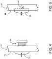
- FIG. 4depicts an example of an adjuster in the form of a thread mechanism 66 used with extension 68.
- Extension 68may be similar to extension 28 of FIG. 2 .
- extension 68includes a display-facing portion 70 and carries one or more permanent magnets to attract with ferromagnetic material in a display device 50. As indicated, operation of thread mechanism 66 adjusts the extent to which foot 72 protrudes inwardly.
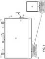
- FIG. 5depicts another example of an adjuster in the form of a cam mechanism 80 used with extension 82.
- Extension 82may be similar to extension 28 of FIG. 2 .
- extension 82includes a display-facing portion 84 and carries one or more permanent magnets to attract with ferromagnetic material in a display device 50.
- operation of cam mechanism 80adjusts the extent to which foot 86 protrudes inwardly.
- Cam mechanism 80may be adjusted with a knob, recessed screw, or any other suitable structure/mechanism.
- FIG. 6depicts another example of a spacer element to space one or more magnets from the rear surface of a display device 50, where the magnets are carried on or part of an extension similar to extension 28 of FIG. 2 .
- the spacer element in the depicted exampletakes the form of a layer of material 90 that covers magnet 92 and is positioned between the magnet and the rear surface 38 of the display device 26 shown in FIG. 2 .
- FIG. 7is a side view depicting a further example of an extension 100 that may be used in connection with the mounting apparatuses 22 discussed herein.
- Extension 100may be similar to extension 28 of FIG. 2 , in that the extension 100 extends along rear surface 38 of the display device 26 and carries a permanent magnet 102.
- the permanent magnet 102is recessed into the display-facing portion of the extension 100. Recessing the permanent magnet 102 in this manner can create a spacing from the display device 26 to provide a desired amount of holding force.
- a mounting apparatusfor selectively mounting a computing accessory to a display device.
- the mounting apparatusincludes an attachment portion configured to hold a computing accessory body; and an extension extending away from the attachment portion and including one or more permanent magnets, where the attachment portion and extension are configured such that, when the mounting apparatus is in a mounted location on the display device, (i) a display-facing portion of the extension extends along and faces a rear surface of the display device; (ii) the one or more permanent magnets attract the extension to ferromagnetic material in the display device to magnetically hold the mounting apparatus in the mounted location; and (iii) the attachment portion holds the computing accessory body adjacent an outer edge of the display device.
- the extensionmay be configured to enable the mounting apparatus to be relocated to a different mounted location so that the attachment portion holds the computing accessory body in a different position adjacent the outer edge of the display device.
- the attachment portionmay be configured to enable the computing accessory body to be selectively held on and removed from the attachment portion.
- the mounting apparatusmay further include a positioning guide attached to the extension and configured to abut against the outer edge of the display device when the mounting apparatus is in the mounted location.
- the positioning guidemay be elongated and extend along the outer edge of the display device.
- the positioning guidemay include a portion protruding inwardly over the outer edge toward a front side of the display device.
- the mounting apparatusmay further include a spacer element on the display-facing portion of the extension to space the one or more permanent magnets from the rear surface of the display device.
- the spacer elementmay be a material that covers the one or more permanent magnets and is positioned between the one or more permanent magnets and the rear surface of the display device when the mounting apparatus is in the mounted location.
- the spacer elementmay be a foot that protrudes from the display-facing portion of the extension inwardly toward the rear surface of the display device.
- Theremay be an adjuster operatively coupled to the foot and configured to adjust the extent to which the foot protrudes inwardly.
- the adjustermay include a thread mechanism to adjust the extent of protrusion.
- the adjustermay include a cam mechanism to adjust the extent of protrusion.
- the one or more permanent magnetsmay be recessed into the display-facing portion of the extension.
- a computing accessoryconfigured to be selectively mounted to a display device.
- the computing accessoryincludes a computing accessory body; and an extension attached to the computing accessory body via an attachment portion configured to hold the computing accessory body, the extension extending away from the computing accessory body and including one or more permanent magnets, where the attachment portion and extension are configured such that, when the computing accessory is in a mounted location on the display device, (i) a display-facing portion of the extension extends along and faces a rear surface of the display device; (ii) the one or more permanent magnets attract the extension to ferromagnetic material in the display device to magnetically hold the computing accessory in the mounted location; and (iii) the attachment portion holds the computing accessory body adjacent an outer edge of the display device.
- the extensionmay be configured to enable the computing accessory to be relocated to a different mounted location so that the attachment portion holds the computing accessory body in a different position adjacent the outer edge of the display device.
- the computing accessorymay include a positioning guide attached to the extension and configured to abut against the outer edge of the display device when the computing accessory is in the mounted location, the positioning guide including a portion protruding inwardly over the outer edge toward a front side of the display device.
- the computing accessorymay include a spacer element on the display-facing portion of the extension to space the one or more permanent magnets from the rear surface of the display device.
- the spacer elementmay be a material that covers the one or more permanent magnets and is positioned between the one or more permanent magnets and the rear surface of the display device when the computing accessory is in the mounted location.
- the spacer elementmay be a foot that protrudes from the display-facing portion of the extension inwardly toward the rear surface of the display device, with an adjuster is operatively coupled to the foot and configured to adjust the extent to which the foot protrudes inwardly.
- a computing accessoryconfigured to be selectively mounted to a display device.
- the computing accessoryincludes a computing accessory body; an extension attached to the computing accessory body via an attachment portion configured to hold the computing accessory body, the extension extending away from the computing accessory body and including one or more permanent magnets, where the attachment portion and extension are configured such that, when the computing accessory is in a mounted location on the display device, (i) a display-facing portion of the extension extends along and faces a rear surface of the display device; (ii) the one or more permanent magnets attract the extension to ferromagnetic material in the display device to magnetically hold the computing accessory in the mounted location; and (iii) the attachment portion holds the computing accessory body adjacent an outer edge of the display device; a positioning guide attached to the extension and configured to abut against the outer edge of the display device, the positioning guide including a portion protruding inwardly over the outer edge toward a front side of the display device; where the extension is configured to enable the mounting apparatus to be relocated to a different mounted location
Landscapes
- Engineering & Computer Science (AREA)
- General Engineering & Computer Science (AREA)
- Theoretical Computer Science (AREA)
- Physics & Mathematics (AREA)
- Human Computer Interaction (AREA)
- General Physics & Mathematics (AREA)
- Computer Hardware Design (AREA)
- Electromagnetism (AREA)
- Power Engineering (AREA)
- Mechanical Engineering (AREA)
- Devices For Indicating Variable Information By Combining Individual Elements (AREA)
- Casings For Electric Apparatus (AREA)
- Telephone Set Structure (AREA)
- Toys (AREA)
- Mirrors, Picture Frames, Photograph Stands, And Related Fastening Devices (AREA)
Description
- In a variety of computing environments, it is desirable to mount a computing accessory to a display device. Various attachment mechanisms have been used to achieve such mounting. In some cases a clip structure is used to grasp an edge of the display device. This is often used, for example, with small cameras mounted to the top edge of a display device. Clips, however, can be prone to breakage, e.g., as a result of mishandling or another object bumping against the accessory. Clips can also limit the locations at which the accessory can be mounted, e.g., they are often mainly useful for mounting accessories to the top edge a computer monitor.
- A hook-and-loop fastener, such as Velcro, is another example of an attachment mechanism. This, however, can wear over time so that the holding force becomes insufficient. This also requires selection of a particular mounting location. The accessory therefore cannot be flexibly and easily removed and/or repositioned, and the mounting location cannot be used for another, different, computing accessory. Use of adhesive, such as with various tapes, can also suffer from these disadvantages.
- In some cases the display device itself includes a specific mounting feature specially designed for a particular accessory. For example a stylus dock is sometimes integrated into the edge of a computer monitor. This limits the stylus to being mounted in one location, and it prevents that edge location from potentially being used for a different computing accessory.
US2011/069404 discloses a magnet with a rigid or flexible stem which magnet is placed on the back of a device having a display screen. The stem has a means for attaching a magnifying lens.US2014/159557 discloses a cover with a decorative wrap for covering a screen of a digital frame. Magnets may be embedded in the decorative wrap to hold the cover adjacent thedecorative wrap 20.US2012/273630 discloses a multimedia device stand which includes a holder that may be removably attached to a holder mount.US2014/245592 discloses a graphic panel assembly includes a graphic holder and a hardware assembly. The hardware assembly includes a bored rod having a threaded exterior and a threaded interior and a magnetic foot fixedly mated to the threaded interior of the bored rod.- This Summary is provided to introduce a selection of concepts in a simplified form that are further described below in the Detailed Description. This Summary is not intended to identify key features or essential features of the claimed subject matter, nor is it intended to be used to limit the scope of the claimed subject matter. Furthermore, the claimed subject matter is not limited to implementations that solve any or all disadvantages noted in any part of this disclosure. According to aspects of the present invention there is provided an apparatus as defined in the claims.
- The disclosure provides for a mounting apparatus for selectively and releasably mounting a computing accessory to a display device. The mounting apparatus includes an attachment portion for holding a computing accessory body. An extension extends away from the attachment portion and includes one or more permanent magnets. When the mounting apparatus is in a mounted location on the display device, (i) a display-facing portion of the extension extends along and faces a rear surface of the display device; (ii) the one or more permanent magnets attract the extension to ferromagnetic material in the display device to magnetically hold the mounting apparatus in the mounted location; and (iii) the attachment portion holds the computing accessory body adjacent an outer edge of the display device.
FIG. 1 shows a perspective view of an example of a computing accessory according to one aspect of the disclosure, including a mounting apparatus for selectively mounting a computing accessory body to a display device.FIG. 2 shows a side view of a portion of the mounting apparatus ofFIG. 1 , in a mounted location on a display device, particularly showing an extension of the mounting apparatus including one or more magnets for holding the mounting apparatus to a rear surface of the display device.FIG. 3 depicts an example use scenario including various computing accessories that employ mounting apparatuses similar to that ofFIGS. 1 and 2 , to enable the computing accessories to be positioned adjacent an outer edge of a display device.FIGS. 4 and 5 are side views that depict examples of adjustable feet that may be employed in connection with an extension similar to the extension shown inFIG. 2 .FIG. 6 depicts, for a magnet that may be used in connection with the extension ofFIG. 2 , a material covering the magnet and positioned between the magnet and the rear surface of the display device ofFIG. 2 .FIG. 7 depicts a recessed magnet configuration that may be used in connection with the example ofFIG. 2 .- The present description contemplates a mounting apparatus for a computing accessory. The mounting apparatus enables the computing accessory to be placed in a mounted location on a display device so that the computing accessory body is adjacent an outer edge of the display device. A portion of the mounting apparatus extends along the rear surface of the display device, and carries magnets that attract the extending portion to ferromagnetic material in the display device. In appropriately-configured display devices, this allows the computing accessory to be held securely in any desired location around the outer edge of the display device. The computing accessory can be easily removed and then replaced, in either the original position or another desired location. When multiple computing accessories are employed, the mounting apparatus may allow them to be flexibly deployed and rearranged as desired around the periphery of the display device. If excessive force is applied to the accessory, it may separate and break away from the display device without damaging either the display device or the computing accessory.
- Referring now to the figures,
FIG. 1 depicts acomputing accessory 20 according to the present description, including amounting apparatus 22 and acomputing accessory body 24. Themounting apparatus 22 is configured such that thecomputing accessory 20 can be selectively mounted to one or more mounted locations on a display device, such asdisplay device 26 ofFIG. 2 (showing a side view of an upper edge portion the display device 26). For ease of illustration,FIG. 2 omits certain components ofFIG. 1 , and focuses on a side view of anextension 28 of themounting apparatus 22. - In the example of
FIG. 1 ,computing accessory body 24 takes the form of a depth camera, for example to be positioned at the top edge of a television or computer monitor. However, the mounting mechanisms described herein can be used on a nearly limitless range of other computing accessories. Other examples include other camera types; speakers or other audio output devices; microphones; keyboards; mice; styluses; gaming controllers; audio headsets; etc. - The description also contemplates accessory mounting on a wide range of display devices. Examples include televisions, computer monitors of various configurations, laptop displays, tablet device displays, mobile phone displays, etc.
- Continuing with the figures,
mounting apparatus 22 may include an attachment portion 30 (FIG. 1 ). When themounting apparatus 22 and computing accessory is in a mounted position/location on a display device, the attachment portion holds thecomputing accessory body 24 adjacent an outer edge of the display device. Though not shown inFIG. 2 , the general location ofcomputing accessory body 24 andattachment portion 30 are indicated at location L, adjacent an outer edge 32 (e.g., the top edge) ofdisplay device 26.Extension 28 extends away fromattachment portion 30 and computingaccessory body 24, and as shown, may include one or morepermanent magnets 34. - The
attachment portion 30 that holds thecomputing accessory body 24 may be configured in various ways. In some examples, theattachment portion 30 allows for the position of thecomputing accessory body 24 to be adjusted relative to the remainder of themounting apparatus 22. Any type of positional adjustment may be employed, including translation along any axis and/or rotation about any axis. In the specific example ofFIG. 1 ,attachment portion 30 enables the depth camera to be pivoted, e.g., to appropriately aim the camera at the scene to be captured. The attachment portion may also be constructed to enable selective removal and attachment of thecomputing accessory body 24, e.g., by implementing it as a specialized dock, through use of magnets, etc. In such a case, themounting apparatus 22 stays in place on the display, while thecomputing accessory body 24 is selectively removed and replaced. Such a configuration may be desirable in the context of a stylus, gaming controller, keyboard or other device that is designed for use at a distance from the display. For these devices, the mountingapparatus 22 provides a convenient and flexible way to dock the accessory when it is not in use. Attachment portion 30 andextension 28 are configured such that, when the computing accessory is in the mounted location on the display device, a display-facingportion 36 of the extension extends along and faces arear surface 38 of display device 26 (FIG. 2 ). In this position,magnets 34 attract the extension toferromagnetic material 40 indisplay device 26. As a result, theattachment portion 30 holds thecomputing accessory body 24 in a location adjacentouter edge 32 of thedisplay device 26.- Mounting
apparatus 22 may further include apositioning guide 42. As best seen inFIG. 2 ,positioning guide 42 may abut againstouter edge 32 of thedisplay device 26, and may protrude inwardly over theouter edge 32 toward afront side 39 of thedisplay device 26. In some cases, the positioning guide may be elongated (i.e., extending into and out of the page inFIG. 2 ), for example so that it extends along all or a significant portion of the length of thecomputing accessory body 24. - Positioning
guide 42 in some cases will facilitate positioning of thecomputing accessory body 24 in a desired location adjacent theouter edge 32 of thedisplay device 26. For example, thepositioning guide 42, by abutting the edge of thedisplay device 26, can serve as a guide for when a user places the computing accessory onto thedisplay device 26, and can prevent further movement of the mountingapparatus 22 toward the interior of the back side of thedisplay device 26. FIG. 3 depicts an exemplary use scenario including adisplay device 50 with a number of different computing accessories positioned at various locations adjacent anouter edge 52 of thedisplay device 50. The figure shows the front side of thedisplay device 50; the computing accessories are magnetically held to the back side of thedisplay device 50 via mountingapparatuses 22 similar to that ofFIGS. 1 and 2 . The computing accessories includespeakers 54,camera 56,keyboard 58 andstylus 60.- As with the example of
FIG. 2 ,display device 50 includes ferromagnetic material that allows the mountingapparatus 22 to hold the computing accessories in place. The ferromagnetic material may be directly on the rear surface of thedisplay device 50, or at some depth within a housing of thedisplay device 50, for example a plastic outer housing. In any case, the ferromagnetic material extends toward the periphery of thedisplay device 50, to enable the computing accessories to be positioned as shown with mountingapparatuses 22 similar to that shown inFIGS. 1 and 2 . The mountingapparatuses 22 discussed herein may be used with a wide variety ofdisplay devices 50, asdisplay devices 50 typically have ferromagnetic material at or slightly under their back surfaces and extending substantially all the way toward the edges of thedisplay device 50. For example, it is common to employ a piece of sheet metal near the back of adisplay device 50 to serve as a structural foundation or for other purposes. - The mounting
apparatuses 22 may be configured so that they can easily be relocated to a different mounted location on thedisplay device 50, so that the associated computingaccessory body 24 is in a different position adjacent theouter edge 32 of thedisplay device 50.FIG. 3 shows an example of this, in whichspeakers 54 may be moved inward towardcamera 56. This could be done to change the stereo separation provided by thespeakers 54, to accommodate placement of other accessories, etc. Further illustrating the flexibility and adaptability of the described mountingapparatuses 22, the mountingapparatus 22 used withkeyboard 58 enables it to be easily mounted in similar fashion to a different display device 62. - In some examples, the attachment portion is configured to enable the
computing accessory body 24 to be selectively held on and removed from the attachment portion. This enables the accessory itself to be removed and replaced while the remainder of the mountingapparatus 22 stays fixed in its mounted location on thedisplay device 50. This can be seen withstylus 60 inFIG. 3 , which can be selectively placed on and removed fromattachment portion 61. In some examples, such an attachment portion will be implemented to magnetically hold the accessory body while the removable accessory is not in use. - In some examples, it will be desirable to provide some amount of spacing between magnets used with the mounting apparatus and the rear surface of the
display device 50. In particular, relatively more or less spacing will affect the magnetic holding strength of the mountingapparatus 22. Spacing may also be desirable to protect the surfaces of the mountingapparatus 22 and/ordisplay device 50 from marring, scratching etc. - Referring to
FIG. 2 , a spacer element may be provided on the display-facingportion 36 ofextension 28. In the depicted example, the spacer element takes the form offeet 64 protruding inwardly towardrear surface 38.Feet 64space magnets 34 from therear surface 38 ofdisplay device 26. The particular length and dimensions of thefeet 64 may be selected to provide a desired magnetic holding force; to provide a desired separation betweenrear surface 38 and the display-facingportion 36 ofextension 28; etc. Material used for thefeet 64 may also be selected to protect against marring and scratching. - In some examples, an adjuster may be provided in connection with a foot to adjust the extent to which the foot protrudes inwardly toward the rear of the
display device 50.FIG. 4 depicts an example of an adjuster in the form of athread mechanism 66 used withextension 68.Extension 68 may be similar toextension 28 ofFIG. 2 . Among other things,extension 68 includes a display-facingportion 70 and carries one or more permanent magnets to attract with ferromagnetic material in adisplay device 50. As indicated, operation ofthread mechanism 66 adjusts the extent to whichfoot 72 protrudes inwardly. FIG. 5 depicts another example of an adjuster in the form of acam mechanism 80 used withextension 82.Extension 82 may be similar toextension 28 ofFIG. 2 . Among other things,extension 82 includes a display-facingportion 84 and carries one or more permanent magnets to attract with ferromagnetic material in adisplay device 50. As indicated, operation ofcam mechanism 80 adjusts the extent to whichfoot 86 protrudes inwardly.Cam mechanism 80 may be adjusted with a knob, recessed screw, or any other suitable structure/mechanism.FIG. 6 depicts another example of a spacer element to space one or more magnets from the rear surface of adisplay device 50, where the magnets are carried on or part of an extension similar toextension 28 ofFIG. 2 . The spacer element in the depicted example takes the form of a layer ofmaterial 90 that coversmagnet 92 and is positioned between the magnet and therear surface 38 of thedisplay device 26 shown inFIG. 2 .FIG. 7 is a side view depicting a further example of anextension 100 that may be used in connection with the mountingapparatuses 22 discussed herein.Extension 100 may be similar toextension 28 ofFIG. 2 , in that theextension 100 extends alongrear surface 38 of thedisplay device 26 and carries apermanent magnet 102. In this example, thepermanent magnet 102 is recessed into the display-facing portion of theextension 100. Recessing thepermanent magnet 102 in this manner can create a spacing from thedisplay device 26 to provide a desired amount of holding force.- It will be understood that the configurations and/or approaches described herein are exemplary in nature, and that these specific embodiments or examples are not to be considered in a limiting sense, because numerous variations are possible.
- The subject matter of the present disclosure is further described in the following paragraphs. According to one aspect, a mounting apparatus for selectively mounting a computing accessory to a display device is provided. The mounting apparatus includes an attachment portion configured to hold a computing accessory body; and an extension extending away from the attachment portion and including one or more permanent magnets, where the attachment portion and extension are configured such that, when the mounting apparatus is in a mounted location on the display device, (i) a display-facing portion of the extension extends along and faces a rear surface of the display device; (ii) the one or more permanent magnets attract the extension to ferromagnetic material in the display device to magnetically hold the mounting apparatus in the mounted location; and (iii) the attachment portion holds the computing accessory body adjacent an outer edge of the display device.
- In this aspect, the extension may be configured to enable the mounting apparatus to be relocated to a different mounted location so that the attachment portion holds the computing accessory body in a different position adjacent the outer edge of the display device.
- In this aspect, the attachment portion may be configured to enable the computing accessory body to be selectively held on and removed from the attachment portion.
- In this aspect, the mounting apparatus may further include a positioning guide attached to the extension and configured to abut against the outer edge of the display device when the mounting apparatus is in the mounted location. The positioning guide may be elongated and extend along the outer edge of the display device. The positioning guide may include a portion protruding inwardly over the outer edge toward a front side of the display device.
- In this aspect, the mounting apparatus may further include a spacer element on the display-facing portion of the extension to space the one or more permanent magnets from the rear surface of the display device. The spacer element may be a material that covers the one or more permanent magnets and is positioned between the one or more permanent magnets and the rear surface of the display device when the mounting apparatus is in the mounted location. The spacer element may be a foot that protrudes from the display-facing portion of the extension inwardly toward the rear surface of the display device. There may be an adjuster operatively coupled to the foot and configured to adjust the extent to which the foot protrudes inwardly. The adjuster may include a thread mechanism to adjust the extent of protrusion. The adjuster may include a cam mechanism to adjust the extent of protrusion.
- In this aspect, the one or more permanent magnets may be recessed into the display-facing portion of the extension.
- According to another aspect, a computing accessory configured to be selectively mounted to a display device is provided. The computing accessory includes a computing accessory body; and an extension attached to the computing accessory body via an attachment portion configured to hold the computing accessory body, the extension extending away from the computing accessory body and including one or more permanent magnets, where the attachment portion and extension are configured such that, when the computing accessory is in a mounted location on the display device, (i) a display-facing portion of the extension extends along and faces a rear surface of the display device; (ii) the one or more permanent magnets attract the extension to ferromagnetic material in the display device to magnetically hold the computing accessory in the mounted location; and (iii) the attachment portion holds the computing accessory body adjacent an outer edge of the display device.
- In this aspect, the extension may be configured to enable the computing accessory to be relocated to a different mounted location so that the attachment portion holds the computing accessory body in a different position adjacent the outer edge of the display device.
- In this aspect, the computing accessory may include a positioning guide attached to the extension and configured to abut against the outer edge of the display device when the computing accessory is in the mounted location, the positioning guide including a portion protruding inwardly over the outer edge toward a front side of the display device.
- In this aspect, the computing accessory may include a spacer element on the display-facing portion of the extension to space the one or more permanent magnets from the rear surface of the display device. The spacer element may be a material that covers the one or more permanent magnets and is positioned between the one or more permanent magnets and the rear surface of the display device when the computing accessory is in the mounted location. The spacer element may be a foot that protrudes from the display-facing portion of the extension inwardly toward the rear surface of the display device, with an adjuster is operatively coupled to the foot and configured to adjust the extent to which the foot protrudes inwardly.
- According to another aspect, a computing accessory configured to be selectively mounted to a display device is provided. The computing accessory includes a computing accessory body; an extension attached to the computing accessory body via an attachment portion configured to hold the computing accessory body, the extension extending away from the computing accessory body and including one or more permanent magnets, where the attachment portion and extension are configured such that, when the computing accessory is in a mounted location on the display device, (i) a display-facing portion of the extension extends along and faces a rear surface of the display device; (ii) the one or more permanent magnets attract the extension to ferromagnetic material in the display device to magnetically hold the computing accessory in the mounted location; and (iii) the attachment portion holds the computing accessory body adjacent an outer edge of the display device; a positioning guide attached to the extension and configured to abut against the outer edge of the display device, the positioning guide including a portion protruding inwardly over the outer edge toward a front side of the display device; where the extension is configured to enable the mounting apparatus to be relocated to a different mounted location so that the attachment portion holds the computing accessory body in different position adjacent the outer edge of the display device; and where the attachment portion is configured to enable the computing accessory body to selectively held on and removed from the attachment portion.
Claims (10)
- A mounting apparatus (22) for enabling a computing accessory (20) to be held securely in a mounting location on the display device (26) and removed from the display device, the mounting apparatus comprising:an attachment portion (30) configured to hold a computing accessory body (24);an extension (28) extending away from the attachment portion and including one or more permanent magnets (34), where the attachment portion and extension are configured such that, when the mounting apparatus is in a mounting location on the display device,(i) a display-facing portion (36) of the extension extends along and faces a rear surface (38) of the display device;(ii) the one or more permanent magnets attract the extension to ferromagnetic material in the display device to magnetically hold the mounting apparatus in the mounting location; and(iii) the attachment portion holds the computing accessory body adjacent an outer edge (32) of the display device;a spacer element (64) on the display-facing portion of the extension to space the one or more permanent magnets from the rear surface of the display device, so as to provide a desired magnetic holding force, where the spacer element is a foot that protrudes from the display-facing portion of the extension toward the rear surface of the display device; andan adjuster (66) operatively coupled to the foot and configured to adjust the extent to which the foot protrudes, so as to affect a magnetic holding strength of the mounting apparatus.
- The mounting apparatus of claim 1, where the extension is further configured to enable the mounting apparatus to be relocated to a different mounting location so that the attachment portion holds the computing accessory body in a different position adjacent the outer edge of the display device.
- The mounting apparatus of claim 1, where the attachment portion is configured to enable the computing accessory body to be selectively held on and removed from the attachment portion.
- The mounting apparatus of claim 1, further comprising a positioning guide attached to the extension and configured to abut against the outer edge of the display device when the mounting apparatus is in the mounting location.
- The mounting apparatus of claim 4, where the positioning guide is elongated and extends along the outer edge of the display device.
- The mounting apparatus of claim 4, where the positioning guide includes a portion protruding over the outer edge toward a front side of the display device.
- The mounting apparatus of claim 1, where the spacer element is a material that covers the one or more permanent magnets and is positioned between the one or more permanent magnets and the rear surface of the display device when the mounting apparatus is in the mounting location.
- The mounting apparatus of claim 1, where the adjuster includes a thread mechanism to adjust the extent of protrusion.
- The mounting apparatus of claim 1, where the adjuster includes a cam mechanism to adjust the extent of protrusion.
- The mounting apparatus of claim 1, where the one or more permanent magnets are recessed into the display-facing portion of the extension.
Applications Claiming Priority (2)
| Application Number | Priority Date | Filing Date | Title |
|---|---|---|---|
| US14/572,219US9717339B2 (en) | 2014-12-16 | 2014-12-16 | Computing accessory mounting apparatus |
| PCT/US2015/063562WO2016099899A1 (en) | 2014-12-16 | 2015-12-03 | Computing accessory mounting apparatus |
Publications (2)
| Publication Number | Publication Date |
|---|---|
| EP3234727A1 EP3234727A1 (en) | 2017-10-25 |
| EP3234727B1true EP3234727B1 (en) | 2018-09-26 |
Family
ID=55022694
Family Applications (1)
| Application Number | Title | Priority Date | Filing Date |
|---|---|---|---|
| EP15816308.9AActiveEP3234727B1 (en) | 2014-12-16 | 2015-12-03 | Computing accessory mounting apparatus |
Country Status (4)
| Country | Link |
|---|---|
| US (1) | US9717339B2 (en) |
| EP (1) | EP3234727B1 (en) |
| CN (1) | CN107111336B (en) |
| WO (1) | WO2016099899A1 (en) |
Families Citing this family (6)
| Publication number | Priority date | Publication date | Assignee | Title |
|---|---|---|---|---|
| GB2567447A (en)* | 2017-10-11 | 2019-04-17 | Catemario Di Quadri Francesco | Furniture Item |
| US11320856B2 (en) | 2018-07-13 | 2022-05-03 | 3M Innovative Properties Company | Display systems and devices |
| US11188119B2 (en)* | 2019-09-18 | 2021-11-30 | International Business Machines Corporation | Portable computer peripheral holder |
| CN113970052B (en)* | 2020-07-22 | 2023-07-21 | 苏州佳世达电通有限公司 | bracket |
| TWI776190B (en)* | 2020-07-22 | 2022-09-01 | 佳世達科技股份有限公司 | Bracket |
| US11901119B2 (en) | 2021-04-01 | 2024-02-13 | Julius Kelly | On-off switchable magnet assembly |
Citations (1)
| Publication number | Priority date | Publication date | Assignee | Title |
|---|---|---|---|---|
| US20140245592A1 (en)* | 2013-03-04 | 2014-09-04 | Target Brands, Inc. | Graphic panel assembly |
Family Cites Families (50)
| Publication number | Priority date | Publication date | Assignee | Title |
|---|---|---|---|---|
| US2876359A (en)* | 1955-06-28 | 1959-03-03 | Plymale Jay Langley | Magnetic support |
| US3221893A (en)* | 1962-11-13 | 1965-12-07 | Eversharp Inc | Article display device |
| US3482910A (en)* | 1967-03-08 | 1969-12-09 | Kennecott Copper Corp | Magnetic support arrangement |
| GB8606515D0 (en)* | 1986-03-17 | 1986-04-23 | Glynn R T | Copyholder |
| US4776549A (en)* | 1987-10-02 | 1988-10-11 | Arjon Mfg. Corp. | Visual effect magnet holder |
| US4960257A (en)* | 1989-05-01 | 1990-10-02 | Waters Daniel F | Easel |
| US5082235A (en)* | 1989-05-30 | 1992-01-21 | William R. Isham | Display mounted document holder |
| US4902078A (en)* | 1989-07-12 | 1990-02-20 | Curtis Manufacturing Company, Inc. | Document holder clip |
| US5803424A (en)* | 1991-07-03 | 1998-09-08 | Optical Coating Laboratory, Inc. | Adjustable hanger for mounting an anti-glare filter on a monitor |
| US5190258A (en)* | 1992-05-26 | 1993-03-02 | Yu Chung C | Articulated support assembly |
| US5639060A (en)* | 1994-03-30 | 1997-06-17 | Spoonts; Sean K. | Mounting bracket for computer speakers |
| US5505421A (en)* | 1995-01-11 | 1996-04-09 | Acco U.S.A., Inc. | Portable paper sheet copyholder |
| US5901937A (en)* | 1997-06-04 | 1999-05-11 | Compeau; Marc S. | Apparatus for attaching personalized fixtures to personal computer and workstation monitors |
| US5890309A (en)* | 1997-12-15 | 1999-04-06 | Markarian; Jean | Pivoting picture frames |
| US6100942A (en)* | 1998-01-31 | 2000-08-08 | Hollenbaugh; Jim | Monitor mountable storage device and speaker holder |
| US6145799A (en)* | 1998-11-05 | 2000-11-14 | Khon; Trinh Cam | Magnetic copy holder for one-handed operation |
| US6311946B1 (en)* | 1998-12-08 | 2001-11-06 | Ladd C. Hoffman | Saddlebag support for computer speakers |
| EP1142443A1 (en)* | 1999-01-04 | 2001-10-10 | Britannia Investment Corporation | Loudspeaker mounting system comprising a flexible arm |
| US6412744B1 (en)* | 1999-10-29 | 2002-07-02 | Dream Find, Inc. | Monitor mounted personal organizer |
| US6290200B1 (en)* | 2000-02-23 | 2001-09-18 | Frank Ko | Collapsible paper, book holder |
| US6888940B1 (en) | 2000-04-12 | 2005-05-03 | Daniel Deppen | Magnetic holder for cell phones and the like |
| US6418010B1 (en)* | 2000-08-11 | 2002-07-09 | Gateway, Inc. | Convertible flat panel display hanging support |
| US6527237B2 (en)* | 2001-07-02 | 2003-03-04 | Harman International Industries Incorporated | Crossbar bracket assembly for speakers and monitors |
| US6543168B1 (en)* | 2001-09-24 | 2003-04-08 | James G. Moore | Computer monitor picture frame |
| US6550737B1 (en)* | 2002-01-30 | 2003-04-22 | Sanjay K. Sai | Computer monitor beverage holder assembly |
| US7431251B2 (en) | 2003-03-27 | 2008-10-07 | Carnevali Jeffrey D | Magnetic mounting platform |
| US7374052B2 (en)* | 2004-01-28 | 2008-05-20 | Mobile Merchandisers, Inc. | Product display support systems and methods |
| US7744051B2 (en)* | 2005-04-26 | 2010-06-29 | Mag Clip Corporation | Magnetic attachment element |
| CA2651430C (en) | 2007-01-18 | 2013-03-19 | Marlite, Inc. | Merchandising support system |
| GB2446612A (en) | 2007-02-13 | 2008-08-20 | Qin Gang | A movable magnetic object holder which secures onto the frame of an LCD monitor |
| US8111865B2 (en)* | 2007-06-05 | 2012-02-07 | Ka Wai Lau | Flat panel speaker mounting system |
| WO2009142723A1 (en)* | 2008-05-19 | 2009-11-26 | Lappin Peter J | Detachable magnifier apparatus |
| US7961068B2 (en) | 2008-05-20 | 2011-06-14 | Cedar Ridge Research, Llc. | Correlated magnetic breakaway device and method |
| US8055009B2 (en)* | 2008-05-23 | 2011-11-08 | Anthony Porter | Mountable audio system for electronic devices |
| TW201018098A (en) | 2008-10-29 | 2010-05-01 | bi-fen Lin | Remote control and an attracting plate thereof |
| US20100116955A1 (en)* | 2008-11-13 | 2010-05-13 | Hayes Richard J | Towel holder and method of manufacture |
| WO2010090753A2 (en) | 2009-02-09 | 2010-08-12 | Patricia Long | Easy-access safety bassinet |
| CN201403181Y (en)* | 2009-04-30 | 2010-02-10 | 曾程远 | Hang type flat-panel sound box for notebook computer |
| US20110064401A1 (en) | 2009-09-11 | 2011-03-17 | Desorbo Alexander P | Coupling and accessory system for electronic devices |
| US8727290B1 (en) | 2010-08-11 | 2014-05-20 | Carlos De La Matta | Flat touch screen mounting system and method |
| US8264310B2 (en) | 2010-09-17 | 2012-09-11 | Apple Inc. | Accessory device for peek mode |
| US20120273630A1 (en) | 2010-10-15 | 2012-11-01 | Jon Simon Gillespie-Brown | Multimedia device stand |
| US20120168582A1 (en)* | 2010-12-30 | 2012-07-05 | Kelly Thomas H | Corner bead magnetic bracket |
| CA2760322A1 (en)* | 2011-12-02 | 2013-06-02 | Robinson, Bruce | Magnetic mud flap attachment device |
| US8567744B1 (en) | 2012-01-03 | 2013-10-29 | The United States Of America, As Represented By The Secretary Of The Navy | Reusable breakaway mounting device |
| CN202617541U (en)* | 2012-04-03 | 2012-12-19 | 鸿富锦精密工业(深圳)有限公司 | Camera fixation structure |
| US20130313387A1 (en)* | 2012-05-25 | 2013-11-28 | Long Ly | Customizable organizer assembly |
| CN103791214B (en) | 2012-10-26 | 2016-10-05 | 深圳市美赛达科技股份有限公司 | A kind of vehicle-mounted flat computer special stand |
| US8839540B2 (en) | 2012-12-06 | 2014-09-23 | Tonia L. Gordon | Digital frame cover and decorative wrap |
| CN203442446U (en)* | 2013-08-19 | 2014-02-19 | 深圳Tcl新技术有限公司 | Camera fixing device and television |
- 2014
- 2014-12-16USUS14/572,219patent/US9717339B2/ennot_activeExpired - Fee Related
- 2015
- 2015-12-03CNCN201580068836.8Apatent/CN107111336B/enactiveActive
- 2015-12-03WOPCT/US2015/063562patent/WO2016099899A1/enactiveApplication Filing
- 2015-12-03EPEP15816308.9Apatent/EP3234727B1/enactiveActive
Patent Citations (1)
| Publication number | Priority date | Publication date | Assignee | Title |
|---|---|---|---|---|
| US20140245592A1 (en)* | 2013-03-04 | 2014-09-04 | Target Brands, Inc. | Graphic panel assembly |
Also Published As
| Publication number | Publication date |
|---|---|
| EP3234727A1 (en) | 2017-10-25 |
| US20160166060A1 (en) | 2016-06-16 |
| WO2016099899A1 (en) | 2016-06-23 |
| CN107111336A (en) | 2017-08-29 |
| US9717339B2 (en) | 2017-08-01 |
| CN107111336B (en) | 2020-06-23 |
Similar Documents
| Publication | Publication Date | Title |
|---|---|---|
| EP3234727B1 (en) | Computing accessory mounting apparatus | |
| US9066421B1 (en) | Holding apparatus for retaining a generally flat-shaped item, such as a hand-held electronic device | |
| US10909274B2 (en) | Screen protection filter | |
| US8934221B2 (en) | Electronic device with support mechanism | |
| US20160091139A1 (en) | Selfie device holder | |
| US8567739B2 (en) | Support apparatus for supporting device | |
| TW201028070A (en) | Hanger | |
| US9146584B2 (en) | Electronic tablet mounting apparatus | |
| US20140346306A1 (en) | Adjustable, amorphous apparatus for positioning screened devices and method for the use thereof | |
| US20150029604A1 (en) | Universal Adjustable Lens Adapter | |
| US20180259118A1 (en) | Adapter Device for Mounting an Optical Device to a Mobile Device | |
| US9106816B1 (en) | Handheld apparatus for demonstrating a screen display | |
| US20190235356A1 (en) | Device for operating a touchscreen and taking self-portraits | |
| US9992885B1 (en) | Retention system | |
| US20140347793A1 (en) | Protective case and electronic device using same | |
| CN102067008A (en) | Detachable Amplifier Unit | |
| US20200116193A1 (en) | Systems and methods for a suction cup device holder | |
| JP3187010U (en) | Thin equipment cover | |
| EP2947782A1 (en) | Holder for mobile terminal | |
| US20120057293A1 (en) | Personal Electronic Device Docking Station | |
| KR101559317B1 (en) | Protection Cover Case with Ringhandle for Mobile Device | |
| EP2958830B1 (en) | Receptacle for an image capture computing device | |
| KR101485262B1 (en) | Apparatus for mounting portable electronic device | |
| JP5955999B1 (en) | Cover mounting structure and ceiling-embedded device | |
| GB2446612A (en) | A movable magnetic object holder which secures onto the frame of an LCD monitor |
Legal Events
| Date | Code | Title | Description |
|---|---|---|---|
| PUAI | Public reference made under article 153(3) epc to a published international application that has entered the european phase | Free format text:ORIGINAL CODE: 0009012 | |
| 17P | Request for examination filed | Effective date:20170523 | |
| AK | Designated contracting states | Kind code of ref document:A1 Designated state(s):AL AT BE BG CH CY CZ DE DK EE ES FI FR GB GR HR HU IE IS IT LI LT LU LV MC MK MT NL NO PL PT RO RS SE SI SK SM TR | |
| AX | Request for extension of the european patent | Extension state:BA ME | |
| DAV | Request for validation of the european patent (deleted) | ||
| DAX | Request for extension of the european patent (deleted) | ||
| GRAP | Despatch of communication of intention to grant a patent | Free format text:ORIGINAL CODE: EPIDOSNIGR1 | |
| INTG | Intention to grant announced | Effective date:20180410 | |
| RIN1 | Information on inventor provided before grant (corrected) | Inventor name:EMERY, WILLIAM LOREN | |
| GRAS | Grant fee paid | Free format text:ORIGINAL CODE: EPIDOSNIGR3 | |
| GRAA | (expected) grant | Free format text:ORIGINAL CODE: 0009210 | |
| AK | Designated contracting states | Kind code of ref document:B1 Designated state(s):AL AT BE BG CH CY CZ DE DK EE ES FI FR GB GR HR HU IE IS IT LI LT LU LV MC MK MT NL NO PL PT RO RS SE SI SK SM TR | |
| REG | Reference to a national code | Ref country code:GB Ref legal event code:FG4D | |
| REG | Reference to a national code | Ref country code:CH Ref legal event code:EP | |
| REG | Reference to a national code | Ref country code:AT Ref legal event code:REF Ref document number:1046784 Country of ref document:AT Kind code of ref document:T Effective date:20181015 | |
| REG | Reference to a national code | Ref country code:IE Ref legal event code:FG4D | |
| REG | Reference to a national code | Ref country code:DE Ref legal event code:R096 Ref document number:602015017261 Country of ref document:DE | |
| REG | Reference to a national code | Ref country code:NL Ref legal event code:FP | |
| PG25 | Lapsed in a contracting state [announced via postgrant information from national office to epo] | Ref country code:SE Free format text:LAPSE BECAUSE OF FAILURE TO SUBMIT A TRANSLATION OF THE DESCRIPTION OR TO PAY THE FEE WITHIN THE PRESCRIBED TIME-LIMIT Effective date:20180926 Ref country code:RS Free format text:LAPSE BECAUSE OF FAILURE TO SUBMIT A TRANSLATION OF THE DESCRIPTION OR TO PAY THE FEE WITHIN THE PRESCRIBED TIME-LIMIT Effective date:20180926 Ref country code:FI Free format text:LAPSE BECAUSE OF FAILURE TO SUBMIT A TRANSLATION OF THE DESCRIPTION OR TO PAY THE FEE WITHIN THE PRESCRIBED TIME-LIMIT Effective date:20180926 Ref country code:LT Free format text:LAPSE BECAUSE OF FAILURE TO SUBMIT A TRANSLATION OF THE DESCRIPTION OR TO PAY THE FEE WITHIN THE PRESCRIBED TIME-LIMIT Effective date:20180926 Ref country code:BG Free format text:LAPSE BECAUSE OF FAILURE TO SUBMIT A TRANSLATION OF THE DESCRIPTION OR TO PAY THE FEE WITHIN THE PRESCRIBED TIME-LIMIT Effective date:20181226 Ref country code:NO Free format text:LAPSE BECAUSE OF FAILURE TO SUBMIT A TRANSLATION OF THE DESCRIPTION OR TO PAY THE FEE WITHIN THE PRESCRIBED TIME-LIMIT Effective date:20181226 Ref country code:GR Free format text:LAPSE BECAUSE OF FAILURE TO SUBMIT A TRANSLATION OF THE DESCRIPTION OR TO PAY THE FEE WITHIN THE PRESCRIBED TIME-LIMIT Effective date:20181227 | |
| REG | Reference to a national code | Ref country code:LT Ref legal event code:MG4D | |
| PG25 | Lapsed in a contracting state [announced via postgrant information from national office to epo] | Ref country code:AL Free format text:LAPSE BECAUSE OF FAILURE TO SUBMIT A TRANSLATION OF THE DESCRIPTION OR TO PAY THE FEE WITHIN THE PRESCRIBED TIME-LIMIT Effective date:20180926 Ref country code:HR Free format text:LAPSE BECAUSE OF FAILURE TO SUBMIT A TRANSLATION OF THE DESCRIPTION OR TO PAY THE FEE WITHIN THE PRESCRIBED TIME-LIMIT Effective date:20180926 Ref country code:LV Free format text:LAPSE BECAUSE OF FAILURE TO SUBMIT A TRANSLATION OF THE DESCRIPTION OR TO PAY THE FEE WITHIN THE PRESCRIBED TIME-LIMIT Effective date:20180926 | |
| REG | Reference to a national code | Ref country code:AT Ref legal event code:MK05 Ref document number:1046784 Country of ref document:AT Kind code of ref document:T Effective date:20180926 | |
| PG25 | Lapsed in a contracting state [announced via postgrant information from national office to epo] | Ref country code:EE Free format text:LAPSE BECAUSE OF FAILURE TO SUBMIT A TRANSLATION OF THE DESCRIPTION OR TO PAY THE FEE WITHIN THE PRESCRIBED TIME-LIMIT Effective date:20180926 Ref country code:PL Free format text:LAPSE BECAUSE OF FAILURE TO SUBMIT A TRANSLATION OF THE DESCRIPTION OR TO PAY THE FEE WITHIN THE PRESCRIBED TIME-LIMIT Effective date:20180926 Ref country code:ES Free format text:LAPSE BECAUSE OF FAILURE TO SUBMIT A TRANSLATION OF THE DESCRIPTION OR TO PAY THE FEE WITHIN THE PRESCRIBED TIME-LIMIT Effective date:20180926 Ref country code:RO Free format text:LAPSE BECAUSE OF FAILURE TO SUBMIT A TRANSLATION OF THE DESCRIPTION OR TO PAY THE FEE WITHIN THE PRESCRIBED TIME-LIMIT Effective date:20180926 Ref country code:AT Free format text:LAPSE BECAUSE OF FAILURE TO SUBMIT A TRANSLATION OF THE DESCRIPTION OR TO PAY THE FEE WITHIN THE PRESCRIBED TIME-LIMIT Effective date:20180926 Ref country code:CZ Free format text:LAPSE BECAUSE OF FAILURE TO SUBMIT A TRANSLATION OF THE DESCRIPTION OR TO PAY THE FEE WITHIN THE PRESCRIBED TIME-LIMIT Effective date:20180926 Ref country code:IT Free format text:LAPSE BECAUSE OF FAILURE TO SUBMIT A TRANSLATION OF THE DESCRIPTION OR TO PAY THE FEE WITHIN THE PRESCRIBED TIME-LIMIT Effective date:20180926 Ref country code:IS Free format text:LAPSE BECAUSE OF FAILURE TO SUBMIT A TRANSLATION OF THE DESCRIPTION OR TO PAY THE FEE WITHIN THE PRESCRIBED TIME-LIMIT Effective date:20190126 | |
| PG25 | Lapsed in a contracting state [announced via postgrant information from national office to epo] | Ref country code:PT Free format text:LAPSE BECAUSE OF FAILURE TO SUBMIT A TRANSLATION OF THE DESCRIPTION OR TO PAY THE FEE WITHIN THE PRESCRIBED TIME-LIMIT Effective date:20190126 Ref country code:SK Free format text:LAPSE BECAUSE OF FAILURE TO SUBMIT A TRANSLATION OF THE DESCRIPTION OR TO PAY THE FEE WITHIN THE PRESCRIBED TIME-LIMIT Effective date:20180926 Ref country code:SM Free format text:LAPSE BECAUSE OF FAILURE TO SUBMIT A TRANSLATION OF THE DESCRIPTION OR TO PAY THE FEE WITHIN THE PRESCRIBED TIME-LIMIT Effective date:20180926 | |
| REG | Reference to a national code | Ref country code:DE Ref legal event code:R097 Ref document number:602015017261 Country of ref document:DE | |
| PG25 | Lapsed in a contracting state [announced via postgrant information from national office to epo] | Ref country code:DK Free format text:LAPSE BECAUSE OF FAILURE TO SUBMIT A TRANSLATION OF THE DESCRIPTION OR TO PAY THE FEE WITHIN THE PRESCRIBED TIME-LIMIT Effective date:20180926 | |
| REG | Reference to a national code | Ref country code:CH Ref legal event code:PL | |
| PLBE | No opposition filed within time limit | Free format text:ORIGINAL CODE: 0009261 | |
| STAA | Information on the status of an ep patent application or granted ep patent | Free format text:STATUS: NO OPPOSITION FILED WITHIN TIME LIMIT | |
| PG25 | Lapsed in a contracting state [announced via postgrant information from national office to epo] | Ref country code:LU Free format text:LAPSE BECAUSE OF NON-PAYMENT OF DUE FEES Effective date:20181203 Ref country code:MC Free format text:LAPSE BECAUSE OF FAILURE TO SUBMIT A TRANSLATION OF THE DESCRIPTION OR TO PAY THE FEE WITHIN THE PRESCRIBED TIME-LIMIT Effective date:20180926 | |
| 26N | No opposition filed | Effective date:20190627 | |
| REG | Reference to a national code | Ref country code:IE Ref legal event code:MM4A | |
| REG | Reference to a national code | Ref country code:BE Ref legal event code:MM Effective date:20181231 | |
| PG25 | Lapsed in a contracting state [announced via postgrant information from national office to epo] | Ref country code:IE Free format text:LAPSE BECAUSE OF NON-PAYMENT OF DUE FEES Effective date:20181203 Ref country code:SI Free format text:LAPSE BECAUSE OF FAILURE TO SUBMIT A TRANSLATION OF THE DESCRIPTION OR TO PAY THE FEE WITHIN THE PRESCRIBED TIME-LIMIT Effective date:20180926 | |
| PG25 | Lapsed in a contracting state [announced via postgrant information from national office to epo] | Ref country code:BE Free format text:LAPSE BECAUSE OF NON-PAYMENT OF DUE FEES Effective date:20181231 | |
| PG25 | Lapsed in a contracting state [announced via postgrant information from national office to epo] | Ref country code:CH Free format text:LAPSE BECAUSE OF NON-PAYMENT OF DUE FEES Effective date:20181231 Ref country code:LI Free format text:LAPSE BECAUSE OF NON-PAYMENT OF DUE FEES Effective date:20181231 | |
| PG25 | Lapsed in a contracting state [announced via postgrant information from national office to epo] | Ref country code:MT Free format text:LAPSE BECAUSE OF NON-PAYMENT OF DUE FEES Effective date:20181203 | |
| PG25 | Lapsed in a contracting state [announced via postgrant information from national office to epo] | Ref country code:TR Free format text:LAPSE BECAUSE OF FAILURE TO SUBMIT A TRANSLATION OF THE DESCRIPTION OR TO PAY THE FEE WITHIN THE PRESCRIBED TIME-LIMIT Effective date:20180926 | |
| PG25 | Lapsed in a contracting state [announced via postgrant information from national office to epo] | Ref country code:HU Free format text:LAPSE BECAUSE OF FAILURE TO SUBMIT A TRANSLATION OF THE DESCRIPTION OR TO PAY THE FEE WITHIN THE PRESCRIBED TIME-LIMIT; INVALID AB INITIO Effective date:20151203 Ref country code:MK Free format text:LAPSE BECAUSE OF NON-PAYMENT OF DUE FEES Effective date:20180926 Ref country code:CY Free format text:LAPSE BECAUSE OF FAILURE TO SUBMIT A TRANSLATION OF THE DESCRIPTION OR TO PAY THE FEE WITHIN THE PRESCRIBED TIME-LIMIT Effective date:20180926 | |
| P01 | Opt-out of the competence of the unified patent court (upc) registered | Effective date:20230430 | |
| PGFP | Annual fee paid to national office [announced via postgrant information from national office to epo] | Ref country code:NL Payment date:20241121 Year of fee payment:10 | |
| PGFP | Annual fee paid to national office [announced via postgrant information from national office to epo] | Ref country code:DE Payment date:20241121 Year of fee payment:10 | |
| PGFP | Annual fee paid to national office [announced via postgrant information from national office to epo] | Ref country code:GB Payment date:20241122 Year of fee payment:10 | |
| PGFP | Annual fee paid to national office [announced via postgrant information from national office to epo] | Ref country code:FR Payment date:20241121 Year of fee payment:10 |