EP3234672B1 - Hardened fiber optic connector with pre-compressed spring - Google Patents
Hardened fiber optic connector with pre-compressed springDownload PDFInfo
- Publication number
- EP3234672B1 EP3234672B1EP14908248.9AEP14908248AEP3234672B1EP 3234672 B1EP3234672 B1EP 3234672B1EP 14908248 AEP14908248 AEP 14908248AEP 3234672 B1EP3234672 B1EP 3234672B1
- Authority
- EP
- European Patent Office
- Prior art keywords
- ferrule
- connector
- fiber optic
- spring
- plug body
- Prior art date
- Legal status (The legal status is an assumption and is not a legal conclusion. Google has not performed a legal analysis and makes no representation as to the accuracy of the status listed.)
- Active
Links
- 239000000835fiberSubstances0.000titleclaimsdescription237
- 239000013307optical fiberSubstances0.000claimsdescription78
- 238000000034methodMethods0.000claimsdescription19
- 230000008878couplingEffects0.000claimsdescription18
- 238000010168coupling processMethods0.000claimsdescription18
- 238000005859coupling reactionMethods0.000claimsdescription18
- 239000000853adhesiveSubstances0.000claimsdescription11
- 230000001070adhesive effectEffects0.000claimsdescription11
- 230000006835compressionEffects0.000claimsdescription6
- 238000007906compressionMethods0.000claimsdescription6
- 230000013011matingEffects0.000description29
- 238000005253claddingMethods0.000description7
- 238000007789sealingMethods0.000description7
- 239000004593EpoxySubstances0.000description6
- 238000003780insertionMethods0.000description6
- 230000037431insertionEffects0.000description6
- 239000000428dustSubstances0.000description5
- 239000000463materialSubstances0.000description5
- 239000002184metalSubstances0.000description5
- 230000000717retained effectEffects0.000description5
- 238000004891communicationMethods0.000description4
- 230000006870functionEffects0.000description4
- 238000004519manufacturing processMethods0.000description3
- 230000008569processEffects0.000description3
- 239000000356contaminantSubstances0.000description2
- 230000007613environmental effectEffects0.000description2
- 230000003287optical effectEffects0.000description2
- 238000004904shorteningMethods0.000description2
- 238000004873anchoringMethods0.000description1
- 239000004760aramidSubstances0.000description1
- 229920003235aromatic polyamidePolymers0.000description1
- 230000008901benefitEffects0.000description1
- 238000004140cleaningMethods0.000description1
- 230000000694effectsEffects0.000description1
- 230000002708enhancing effectEffects0.000description1
- 230000004927fusionEffects0.000description1
- 238000005498polishingMethods0.000description1
- 238000002360preparation methodMethods0.000description1
- 230000003014reinforcing effectEffects0.000description1
- 238000007493shaping processMethods0.000description1
Images


Classifications
- G—PHYSICS
- G02—OPTICS
- G02B—OPTICAL ELEMENTS, SYSTEMS OR APPARATUS
- G02B6/00—Light guides; Structural details of arrangements comprising light guides and other optical elements, e.g. couplings
- G02B6/24—Coupling light guides
- G02B6/36—Mechanical coupling means
- G02B6/38—Mechanical coupling means having fibre to fibre mating means
- G02B6/3807—Dismountable connectors, i.e. comprising plugs
- G02B6/381—Dismountable connectors, i.e. comprising plugs of the ferrule type, e.g. fibre ends embedded in ferrules, connecting a pair of fibres
- G02B6/3818—Dismountable connectors, i.e. comprising plugs of the ferrule type, e.g. fibre ends embedded in ferrules, connecting a pair of fibres of a low-reflection-loss type
- G02B6/3821—Dismountable connectors, i.e. comprising plugs of the ferrule type, e.g. fibre ends embedded in ferrules, connecting a pair of fibres of a low-reflection-loss type with axial spring biasing or loading means
- G—PHYSICS
- G02—OPTICS
- G02B—OPTICAL ELEMENTS, SYSTEMS OR APPARATUS
- G02B6/00—Light guides; Structural details of arrangements comprising light guides and other optical elements, e.g. couplings
- G02B6/24—Coupling light guides
- G02B6/36—Mechanical coupling means
- G02B6/38—Mechanical coupling means having fibre to fibre mating means
- G02B6/3807—Dismountable connectors, i.e. comprising plugs
- G02B6/381—Dismountable connectors, i.e. comprising plugs of the ferrule type, e.g. fibre ends embedded in ferrules, connecting a pair of fibres
- G02B6/3816—Dismountable connectors, i.e. comprising plugs of the ferrule type, e.g. fibre ends embedded in ferrules, connecting a pair of fibres for use under water, high pressure connectors
- G—PHYSICS
- G02—OPTICS
- G02B—OPTICAL ELEMENTS, SYSTEMS OR APPARATUS
- G02B6/00—Light guides; Structural details of arrangements comprising light guides and other optical elements, e.g. couplings
- G02B6/24—Coupling light guides
- G02B6/36—Mechanical coupling means
- G02B6/38—Mechanical coupling means having fibre to fibre mating means
- G02B6/3807—Dismountable connectors, i.e. comprising plugs
- G02B6/381—Dismountable connectors, i.e. comprising plugs of the ferrule type, e.g. fibre ends embedded in ferrules, connecting a pair of fibres
- G02B6/3825—Dismountable connectors, i.e. comprising plugs of the ferrule type, e.g. fibre ends embedded in ferrules, connecting a pair of fibres with an intermediate part, e.g. adapter, receptacle, linking two plugs
- G—PHYSICS
- G02—OPTICS
- G02B—OPTICAL ELEMENTS, SYSTEMS OR APPARATUS
- G02B6/00—Light guides; Structural details of arrangements comprising light guides and other optical elements, e.g. couplings
- G02B6/24—Coupling light guides
- G02B6/36—Mechanical coupling means
- G02B6/38—Mechanical coupling means having fibre to fibre mating means
- G02B6/3807—Dismountable connectors, i.e. comprising plugs
- G02B6/3833—Details of mounting fibres in ferrules; Assembly methods; Manufacture
- G02B6/3847—Details of mounting fibres in ferrules; Assembly methods; Manufacture with means preventing fibre end damage, e.g. recessed fibre surfaces
- G02B6/3849—Details of mounting fibres in ferrules; Assembly methods; Manufacture with means preventing fibre end damage, e.g. recessed fibre surfaces using mechanical protective elements, e.g. caps, hoods, sealing membranes
- G—PHYSICS
- G02—OPTICS
- G02B—OPTICAL ELEMENTS, SYSTEMS OR APPARATUS
- G02B6/00—Light guides; Structural details of arrangements comprising light guides and other optical elements, e.g. couplings
- G02B6/24—Coupling light guides
- G02B6/36—Mechanical coupling means
- G02B6/38—Mechanical coupling means having fibre to fibre mating means
- G02B6/3807—Dismountable connectors, i.e. comprising plugs
- G02B6/3869—Mounting ferrules to connector body, i.e. plugs
- G02B6/3871—Ferrule rotatable with respect to plug body, e.g. for setting rotational position ; Fixation of ferrules after rotation
- G—PHYSICS
- G02—OPTICS
- G02B—OPTICAL ELEMENTS, SYSTEMS OR APPARATUS
- G02B6/00—Light guides; Structural details of arrangements comprising light guides and other optical elements, e.g. couplings
- G02B6/24—Coupling light guides
- G02B6/36—Mechanical coupling means
- G02B6/38—Mechanical coupling means having fibre to fibre mating means
- G02B6/3807—Dismountable connectors, i.e. comprising plugs
- G02B6/3887—Anchoring optical cables to connector housings, e.g. strain relief features
- G02B6/3889—Anchoring optical cables to connector housings, e.g. strain relief features using encapsulation for protection, e.g. adhesive, molding or casting resin
- G—PHYSICS
- G02—OPTICS
- G02B—OPTICAL ELEMENTS, SYSTEMS OR APPARATUS
- G02B6/00—Light guides; Structural details of arrangements comprising light guides and other optical elements, e.g. couplings
- G02B6/24—Coupling light guides
- G02B6/36—Mechanical coupling means
- G02B6/38—Mechanical coupling means having fibre to fibre mating means
- G02B6/3807—Dismountable connectors, i.e. comprising plugs
- G02B6/389—Dismountable connectors, i.e. comprising plugs characterised by the method of fastening connecting plugs and sockets, e.g. screw- or nut-lock, snap-in, bayonet type
- G02B6/3894—Screw-lock type
Definitions
- the present inventionrelates to a fiber optic connector and to a method for assembling a fiber optic connector.
- Fiber optic communication systemsare becoming prevalent in part because service providers want to deliver high bandwidth communication capabilities (e.g., data and voice) to customers.
- Fiber optic communication systemsemploy a network of fiber optic cables to transmit large volumes of data and voice signals over relatively long distances.
- Optical fiber connectorsare an important part of most fiber optic communication systems. Fiber optic connectors allow two optical fibers to be quickly optically connected together without requiring a splice, and also allow such optical fibers to be easily disconnected from one another. Fiber optic connectors can be used to optically interconnect two lengths of optical fiber. Fiber optic connectors can also be used to interconnect lengths of optical fiber to passive and active equipment.
- a typical fiber optic connectorincludes a ferrule assembly supported at a distal end of a connector housing.
- a springis used to bias the ferrule assembly in a distal direction relative to the connector housing.
- the ferrulefunctions to support an end portion of at least one optical fiber (in the case of a multi-fiber ferrule, the ends of multiple fibers are supported).
- the ferrulehas a distal end face at which a polished end of the optical fiber is located.
- the optical fibers of two connected fiber optic connectorsare coaxially aligned such that the end faces of the optical fibers directly oppose one another. In this way, an optical signal can be transmitted from optical fiber to optical fiber through the aligned end faces of the optical fibers.
- alignment between two fiber optic connectorsis provided through the use of an intermediate fiber optic adapter (see U.S. Patent No. 5,317,663 ) having a sleeve that receives and aligns the respective ferrules supporting the optical fibers desired to be optically coupled together.
- Ruggedized (i.e., hardened) fiber optic connection systemsinclude fiber optic connectors and fiber optic adapters suitable for outside environmental use. These types of systems are typically environmentally sealed and include robust fastening arrangements suitable for withstanding relatively large pull loading and side loading.
- Example ruggedized fiber optic connection systemsare disclosed by US. Patent Nos. 7,467,896 ; 7,744,288 and 8,556,520 . Improvements are needed in the areas of ease of assembly, manufacturability and performance.
- EP-B1-1443350 , WO-A2-2006/076061 and US-A1-2002/0118928relate to fibre optic connectors.
- the present inventionconcerns to a method for assembling a fibre optic connector according to claim 1 and a fibre optic connector according to claim 11.
- FIG. 1illustrated a hardened fiber optic connection system 20.
- the hardened fiber optic connection system 20includes a fiber optic adapter 22 configured for coupling a non-hardened fiber optic connector 24 (e.g., an SC-type connector) to a hardened fiber optic connector 26.
- the fiber optic adapter 22is configured to be mounted in sealed relation relative to a bulk head, panel, wall of an enclosure or other structure.
- the fiber optic adapter 22includes a first port 28 for receiving the non-hardened fiber optic connector 24 and an opposite second port 30 for receiving the hardened fiber optic connector 26. When the hardened fiber optic connector 26 is secured within the second port 30, a sealed relationship preferably exists between the hardened fiber optic connector 26 and the fiber optic adapter 22.
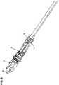
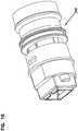
- the hardened fiber optic connector 26can include a seal 32 that forms a radial seal within the second port 30. Additionally, the hardened fiber optic connector 26 can include a plug body 34 having a plug end 36 that is received within the second port 30. As shown at Figure 2 , the hardened fiber optic connector 26 can include a ferrule 38 that is accessible at the plug end 36.
- the plug end 36can include a keying structure (e.g., a rail, tab, flat, non-symmetrical characteristic, etc.) that mates with a corresponding keying structure within the second port 30 to ensure that the plug end 36 is inserted into the second port 30 at a particular rotational orientation.
- the hardened fiber optic connector 26can also include a fastening element 40 for securing the hardened fiber optic connector 26 within the second port 30.
- the fastening element 40can have a robust configuration capable of withstanding axial loads in excess of 100 pounds.
- the fastening element 40is rotatable relative to the plug body 34 and includes threads 42 that mate with corresponding threads 44 of the second port 30.
- the fastening element 40 of the hardened fiber optic connectorhas a robust configuration for mechanically coupling the hardened fiber optic connector 26 to the fiber optic adapter 22.
- the fastening element 40is free to rotate about a central longitudinal axis of the hardened fiber optic connector 26.
- the fastening element 40includes a coupling nut having external threads adapted to engage internal threads of the mating fiber optic adapter 22.
- the fastening elementcan include a coupling sleeve having internal threads that engage corresponding external threads of the mating fiber optic adapter.
- the robust couplingcan be provided by a bayonet-style coupling arrangement between the fastening element and the mating fiber optic adapter.
- the interface between the hardened fiber optic connector 26 and its mating fiber optic adapter 22is preferably environmentally sealed by a sealing arrangement configured to limit or prevent the intrusion of moisture, dust or other contaminants.
- the sealing arrangementcan include one or more sealing members (e.g., O-rings, radial seals, face seals, or other gasket-type seals mounted on the plug body 34, on a shroud surrounding the plug body, or on/in the fiber optic adapter).
- the hardened fiber optic connector 26is configured to terminate a fiber optic cable 46.
- the fiber optic cableincludes an optical fiber 48 protected within a jacket 50.
- the jacket 50can have an elongated transverse cross-section so as to have a generally "flat" configuration.
- the fiber optic cable 46can also include one or more strength elements 52.
- the strength elements 52are positioned on opposite sides of the optical fiber 48.
- strength elements 52can include aramid yarn, rods made of fiber reinforced epoxy or other materials, metal members strands or braids, or other structures.
- the hardened fiber optic connector 26includes a connector core 54 that mounts within the plug body 34.
- the hardened fiber optic connector 26can also include a dust cap 56 that can be secured over the plug end 36 of the plug body 34 by the fastening element 40 to provide protection of the ferrule 38 when the hardened fiber optic connector 26 is not in use.
- the plug body 34can include a main body 58 and a side cover 60.
- the hardened fiber optic connector 26further can include a metal sleeve 62 for reinforcing the plug body 34, a shape memory sleeve 64 (e.g., a heat shrink sleeve) for providing a seal between the cable jacket 50 and the hardened fiber optic connector 26, a boot 66 for providing strain relief and bend radius protection at the interface between the fiber optic cable 46 and the back end of the hardened fiber optic connector 26, and a lanyard 68 for tethering the dust cap 56 to the hardened fiber optic connector 26.
- a metal sleeve 62for reinforcing the plug body 34
- a shape memory sleeve 64e.g., a heat shrink sleeve
- boot 66for providing strain relief and bend radius protection at the interface between the fiber optic cable 46 and the back end of the hardened fiber optic connector 26
- a lanyard 68for tethering the dust cap 56 to the hardened fiber optic connector 26.
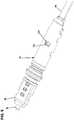
- the connector core 54 of the hardened fiber optic connector 26includes a ferrule subassembly 70, an extension piece 72 and a cable anchor 74.
- the extension piece 72can be mounted between the ferrule subassembly 70 and the cable anchor 74.
- the ferrule subassembly 70attaches to a front end of the extension piece 72 by a mechanical interface such as a snap-fit connection.
- the fiber optic cable 46can be secured to the cable anchor 74.
- the strength elements 52 and the jacket 50can be adhesively secured within the cable anchor 74.
- the cable anchor 74can include interlock structures 78 (e.g., teeth, tabs, ribs, etc.) that interlock with mating structures 79 on the plug body 34 to assist in axially fixing the cable anchor 74 relative to the plug body 34.
- the cable anchor 74can connect to a rear end of the extension piece 72 by a snap-fit connection or other type of mechanical interface.
- the ferrule subassembly 70 of the connector core 54includes the ferrule 38, a ferrule hub 80 coupled to the ferrule 38, a ferrule spring 82 and a spring retainer 84.
- the spring retainer 84is configured to couple to the ferrule hub 80 such that the ferrule spring 82 is captured between the spring retainer 84 and the ferrule hub 80.
- the ferrule hub 80can include tabs 86 that fit within corresponding openings 88 defined by the spring retainer 84. In certain examples, the tabs 86 fit within the openings 88 by a snap-fit connection.
- the spring retainer 84can include an open through-slot 89 that extends through the length of the spring retainer 84 and allows the spring retainer 84 to flex open to allow the tabs 86 to snap-fit within the openings 88.
- the spring retainer 84is configured to allow the ferrule spring 82 to be pre-compressed in an initial compressed state between the ferrule hub 80 and the spring retainer 84 (i.e., the spring holder). In this way, the ferrule spring 82 can be pre-compressed prior to loading the connector core 54 into the plug body 34. In the initial compressed state, the ferrule spring 82 is shorter than in the non-compressed state thereby allowing the pre-assembled ferrule subassembly 70 to be shorter. As described herein, shortening of the ferrule subassembly 70 by pre-compressing the ferrule spring 82 reduces the amount of excess fiber that must be pulled from the connector during the assembly process.
- the ferrule 38 and the corresponding ferrule hub 80move together as a unit relative to the spring retainer 84.
- the ferrule 38 and the ferrune hub 80can be referred to as a ferrule unit 91.
- the ferrule spring 82biases the ferrule unit 91 in a forward direction relative to the spring retainer 84.
- the connection between the spring retainer 84 and the ferrule hub 80limits the range of axial movement that is permissible between the ferrule unit 91 (i.e., the ferrule 38 and its corresponding ferrule hub 80) and the spring retainer 84.
- fiber buckling in the hardened fiber optic connector 26can be precisely predicted, limited and controlled.
- rearward movement of the ferrule unit relative to the spring retainer 84is limited by interference between the tabs 86 and rear ends of the openings 88.
- rearward movement of the ferrule unit relative to the spring retainer 84can be limited by contact between a front flange 92 of the ferrule hub 80 and a forward end 94 of the spring retainer 84.
- the cable anchor 74can be integrated directly into the extension piece 72 thereby allowing the strength elements 52 to be coupled directly to the extension piece 72 without an intermediate cable anchor piece.
- the spring retainer 84is coupled to the ferrule hub 80 by a connection that allows the ferrule unit 91 to slide axially relative to the spring retainer 84 along a limited range of movement defined between first and second axial positions.
- the ferrule spring 82biases the ferrule unit toward the first axial position.
- the coupling between the ferrule hub 80 and the spring retainer 84can provide a positive stop that stops forward movement of the ferrule unit 91 relative to the spring retainer 84 at the first axial position.
- the coupling between the ferrule hub 80 and the spring retainer 84can also provide a positive stop that stops rearward movement of the ferrule unit relative to the spring retainer 84 at the second axial position.
- the ferrule unitis rotationally keyed relative to the spring retainer 84 such that relative rotation between the ferrule unit and the spring retainer 84 is prevented.
- the first positive stopcan be provided by contact between the tabs 86 and forward ends of the openings 88.
- the second positive stopcan be provided by contact between the front flange 92 of the ferrule hub 80 and the forward end 94 of the spring retainer 84.
- the ferrule 38includes a front face 96 that can be polished.
- An optical fiber stub 98is secured within a longitudinal bore of the ferrule 38.
- the optical fiber stub 98has a front end 100 positioned at the front face 96 of the ferrule 38 and a rear end portion 102 that projects rearwardly from a rear end of the ferrule 38.
- the rear end portion 102 of the optical fiber stub 98can be spliced to the optical fiber 48 of the fiber optic cable 46 at a splice location 104.
- the splice location 104can be protected within the ferrule hub 80.
- the ferrule hub 80can include the front flange 92 that is secured to the ferrule 38 prior to splicing, and a rear hub portion 106 that can be secured to the rear end of the ferrule 38 after splicing.
- the rear hub portion 106can include an outer shell 108 that abuts against a back side of the front flange 92.
- the outer shell 108can include a longitudinal slot 110 that allows the outer shell 108 to be inserted over the splice location 104 after splicing.
- the outer shell 108can define a port 112 for allowing a splice encapsulating material 113 such as adhesive to be injected into the interior of the outer shell 108 to encapsulate and protect the splice location 104.
- the tabs 86 for mechanically interfacing with the spring retainer 84can be provided on the outer shell 108.
- the front flange 92can be configured to mate with the interior of the plug body 34 so as to prevent relative rotation between the ferrule hub 80 and the plug body 34.
- the front flange 92can include a plurality of flats 114 that oppose corresponding flats defined within the interior of the plug body 34 so as to prevent relative rotation between the ferrule hub 80 and the plug body 34.
- the front flange 92can include front angled surfaces 116 that preferably seat against corresponding surfaces defined within the plug end 36 of the plug body 34 when the connector core 54 is loaded therein.
- the optical fiber 48may be fixed relative to the hardened fiber optic connector 26 by adhesive at the cable anchor 74.
- the optical fiber 48is prevented from pushing back into the fiber optic cable 46.
- this fiber buckling spaceis provided by the extension piece 72.
- the extension piece 72is elongated and extends a majority of the length of the plug body 34.
- the ferrule subassembly 70is configured to precisely control the range of movement of the ferrule 38 and provides positive stops for preventing the ferrule 38 from being moved rearwardly beyond a predetermined limit. Therefore, the degree of buckling that is to be accommodated within the extension piece 72 is predetermined and controlled.
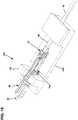
- the extension piece 72also includes a mechanical interlock feature 120 (see Fig. 7 ) adapted to interlock or otherwise mechanically engage with the plug body 34.
- the interlock feature 120includes a tab that fits within a corresponding opening 122 defined by the plug body 34 (see Fig. 9 ).
- the connector core 54is preassembled prior to insertion within the plug body 34.
- the ferrule subassembly 70is preassembled and the ferrule spring 82 is pre-compressed and retained in the initial compressed state by the spring retainer 84.
- the front angled surfaces 116 of the ferrule hub 80abut against the corresponding surfaces provided within the plug end 36 of the plug body 34 and a secondary compression force is applied to the ferrule spring 82 as the connector core 54 is loaded into the plug body 34. This secondary compression force is sufficient to move the ferrule spring 82 from the initial compressed state to a final compressed state.
- the front angled surfaces 116are biased firmly against the corresponding angled surfaces at the plug end 36 of the plug body 34, and the ferrule unit is forced slightly rearwardly with respect to the forward positive stop position defined by the mechanical interface between the ferrule hub 80 and the spring retainer 84.
- This secondary compression stepassures that the front angled surfaces 116 are properly seated against the plug end 36 of the plug body 34, and that any tolerances in the manufacturing process have been taken up.
- the interlock feature 120 and the corresponding opening 122are relatively positioned such that the mechanical interlock fixes the connector core 54 in the appropriate axial position relative to the plug body 34 where the ferrule spring 82 is secured and retained in the final compressed state.
- the plug body 34generally defines the central longitudinal axis 41, and that axial movement referred to herein is made with reference to such a central longitudinal axis 41.
- the fiber optic cable 46is initially prepared using stripping, cleaving and cleaning operations. As so prepared, an end portion of the jacket 50 is removed to expose the optical fiber 48 and end portions of the strength elements 52. After preparation of the fiber optic cable 46, the cable anchor 74 and the ferrule spring 82 can be inserted over the optical fiber 48 and the optical fiber 48 can be fusion spliced to the optical fiber stub 98 of the ferrule 38 at the splice location 104 (see Fig. 4 ).
- the outer shell 108 of the ferrule hub 80can be laterally inserted over the splice location 104 and filled with adhesive or other encapsulating material 113 that encapsulates and protects the splice location 104 (see Fig. 5 ).
- the ferrule subassembly 70is then assembled by sliding the ferrule spring 82 forwardly into engagement with the ferrule hub 80 and inserting the spring retainer 84 laterally over the spliced optical fiber stub 98 and optical fiber 48 via the through-slot 89 at a location behind the ferrule spring 82.
- the spring retainer 84is then slid forwardly over the rear hub portion 106 causing the ferrule spring 82 to be axially compressed between the spring retainer 84 and the ferrule hub 80.
- the precompression of the ferrule spring 82causes the ferrule spring 82 to be shortened and retained in an initial compressed state.
- the spring retainer 84is moved forwardly until the tabs 86 of the ferrule hub 80 snap within the openings 88 of the spring retainer 84 such that the spring retainer 84 is effectively coupled to the ferrule hub 80.
- the ferrule spring 82is captured and retained in the initial compressed state by the spring retainer 84 via its coupling to the ferrule hub 80.
- Figure 6shows the preassembled ferrule subassembly 70.
- the extension piece 72is installed between the spring retainer 84 and the cable anchor 74. Snap-fit connections may be provided between the spring retainer 84 and the front end of the extension piece 72 and between the cable anchor 74 and the rear end of the extension piece 72.
- Figure 7shows the pre-assembled connector core 54 prior to insertion within the plug body 34. After the connector core 54 has been preassembled, the connector core is inserted axially into the plug body 34 as shown at Figure 7 .
- the connector core 54is inserted axially into the plug body 34 until the front angled surfaces 116 at the front side of the ferrule hub 80 engage a stop structure at the inside of the plug end 36 of the plug body 34 and sufficient axial pressure is applied to the connector core 54 to move the ferrule spring 82 from the initial compressed state to a final compressed state. It will be appreciated that the interlock feature 120 of the connector core 54 snaps within the opening 122 of the plug body 34 when the connector core 54 has been inserted sufficiently within the plug body 34 for the ferrule spring 82 to move from the initial compressed state to the final compressed state.
- interlock feature 120 and the opening 122function to secure the connector core 54 and its corresponding ferrule subassembly 70 in an axial position relative to the plug body 34 where the ferrule spring 82 is retained in the final compressed state.
- Figures 8 and 9show the connector core 54 fully loaded within the plug body 34.
- the assemblycan be loaded into a fixture 130 having a first portion 132 that engages a forward portion of the plug body 34 and a second portion 134 that can attach (e.g., clamp) to the fiber optic cable 46.
- a spring 136can be provided between the first and second portions 132, 134 to exert a biasing force on the second portion 134 that biases the second portion 134 in a rearward direction relative to the first portion 132. In this way, the fiber optic cable 46 is pulled rearwardly relative to the plug body 34 to cause any excess fiber length within the connector core 54 to be taken up.
- the spring 136has a spring force that is equal to or less than a corresponding spring force of the ferrule spring 82. In this way, further compressive load is not applied to the ferrule spring 82 which would cause the ferrule spring 82 to apply tension to the optical fiber 48.
- adhesive materialsuch as epoxy can be injected into the cable anchor 74 to secure the strength elements 52 and thus the fiber optic cable 46 at the set axial position relative to the plug body 34 where excess fiber length is not provided within the connector core 54. After curing of the adhesive, the assembly can be removed from the fixture 130 and the remainder of the assembly process can take place.
- side cover 60 of the plug body 34can be installed on the main body 58 of the plug body 34.
- the shape memory sleeve 64can be slid over the rear portion of the plug body 34, the heat shrink can be applied over the interface between the hardened fiber optic connector 26 and the fiber optic cable 46, the fastening element 40 can be slid over the metal sleeve 62 and the boot 66 can be installed at the rear of the plug body 34.
- componentssuch as the boot 66, the shape memory sleeve 64, and metal sleeve 62 and the fastening element 40 can be slid over the fiber optic cable 46.
- a typical single fiber optical connectorincludes a ferrule having an outer cylindrical surface that functions as a reference surface when the ferrule is received within an alignment sleeve of a fiber optic adapter.
- the ferrulealso defines a central axial passageway in which the optical fiber is secured.
- the optical fiberis secured in the central axial passageway with the fiber core perfectly concentric with the outer cylindrical surface of the ferrule.
- the fiber coreis not typically perfectly concentric with the outer cylindrical surface.
- Fiber core eccentricitycan be defined as the distance between the central longitudinal axis of the fiber core (i.e., the fiber core axis) and the central longitudinal axis defined by the ferrule outer cylindrical surface (i.e., the ferrule axis).
- the direction that the fiber core axis is offset from the ferrule axiscan be referred to as the direction of core eccentricity.
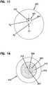
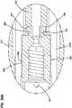
- FIG. 11shows an end view of a ferrule 220 holding an optical fiber 221 having a fiber core 222 and a cladding 224.
- the cladding 224typically has a different index of refraction as compared to the fiber core 222 so that light transmitted through the optical fiber 221 can be contained generally within the fiber core 222 by total internal reflection.
- the fiber core 222is not centered relative to an outer cylindrical surface of the ferrule 220. Rather, a fiber core axis A C of the fiber core 222 is offset from a central longitudinal axis A F of the ferrule 220. In the example shown, the fiber core axis A C is offset upwardly relative to the outer cylindrical surface of the ferrule 220.
- the fiber core axis A Ccan be offset in any other direction relative to the outer cylindrical surface of the ferrule 220.
- the distance EC by which the fiber core axis A C is offset from the central longitudinal axis A F of the ferrule 220corresponds to the fiber core eccentricity and is exaggerated for the purpose of illustration.
- Other fiber core eccentricitiescan occur due to the fiber being offset within the opening of the ferrule, even if it is centrally located in the ferrule, and/or if the core is not concentric with the cladding of the fiber.
- fiber core eccentricityDue to fiber core eccentricity, signal losses within a system can occur at the connection between two optical fibers. This is because fiber core eccentricity prevents the fiber cores of the optical fibers being optically coupled together from being perfectly co-axially aligned.
- the worst-case scenariooccurs when the ferrules of two fiber optic connectors being coupled together have directions of core eccentricity that are 180 degrees out of phase with respect to each other.
- Tuningtypically involves rotating the ferrule to intentionally position the direction of core eccentricity of the ferrule at a particular rotational orientation relative to one or more keyed components of the fiber optic connector.
- Example tuning techniquesare disclosed at PCT Publication No. WO 02/052310 and at U.S. Patent No. 5,212,752 ).
- the hardened fiber optic connector 26is depicted as a splice-on fiber optic connector.
- the ferrule 38supports the optical fiber stub 98 that is spliced to the optical fiber 48 of the fiber optic cable 46.
- the front end 100 of the optical fiber stub 98 as well as the front face 96 of the ferrule 38can be pre-processed using processing techniques such as polishing, cleaving, shaping, laser processing or other processing techniques.
- a direction of core eccentricity of the optical fiber stub 98 relative to the ferrule 38can be determined and marked on the ferrule 38 or the front flange 92 of the ferrule hub.
- the direction of core eccentricity of the ferrule assemblycan be taken into consideration. For example, tuning can be accomplished by orienting the direction of core eccentricity at a particular rotational orientation relative to the fiber optic cable 46 prior to splicing.
- the direction of core eccentricitycan also be oriented at a particular orientation relative to the plug body 34 prior to splicing. In this way, after splicing, the hardened fiber optic connector 26 is tuned such that the core offset is oriented in a desired rotational orientation about the central longitudinal axis of the ferrule 38.
- FIGS. 12 and 13depict another hardened fiber optic connector 310.
- the hardened fiber optic connector 310is shown terminating a fiber optic cable 312 having an optical fiber 314 and strength members 316 surrounded by a jacket 315.
- the optical fiber 314can include a core 307 surrounded by a cladding layer 309.
- a loose or tight buffer 305can be provided between the optical fiber 314 and the strength members 316.
- the hardened fiber optic connector 310includes a strain relief boot 311 that extends over the fiber optic cable 312.
- the strain relief boot 311couples to an outer shroud 317 disposed about an inner arrangement 313 ( FIG. 13 ) including a tunable connector core 321 (see FIGS.
- a robust fastening element 319mounts over the shroud 317 and can be rotated relative to the outer shroud 317 about a central longitudinal axis of the hardened fiber optic connector 310.
- the hardened fiber optic connector 310directly terminates the optical fiber 314 of the fiber optic cable 312 without any intermediate splices.
- a tuning featureis integrated into the tunable connector core 321 to allow the hardened fiber optic connector 310 to be readily tuned (i.e., the fiber core eccentricity of the ferrule can be set at a desired rotational orientation relative to a keyed component of the connector such as the shroud, the plug body or both) after mounting on the optical fiber 314 to provide enhanced performance (e.g., low insertion loss).
- the outer shroud 317has a keying feature 318 that ensures the hardened fiber optic connector 310 is loaded into a mating connecting component (e.g., a mating fiber optic adapter or a mating fiber optic connector) at a particular rotational orientation.
- FIG. 15shows an example mating fiber optic adapter 349.
- the keying feature 318is shown as a female structure such as a notch/slot adapted to mate with a corresponding male feature (e.g., a key, rail, projection, tab, etc.) of the mating fiber optic adapter.
- the keying feature 318can include a male structure (e.g., one or more tabs, keys, rails, projections, etc.) that mates with a corresponding female structure of the mating fiber optic adapter.
- the robust fastening element 319 of the hardened fiber optic connector 310is configured for mechanically coupling the hardened fiber optic connector 310 to its corresponding fiber optic adapter 349.
- the fastening element 319mounts over the outer shroud 317 and is free to rotate about the outer shroud 317.
- the robust fastening element 319includes coupling nut having external threads adapted to engage internal threads of the mating fiber optic adapter.
- the fastening elementcan include a coupling sleeve having internal threads that engage external threads of the mating fiber optic adapter.
- the robust couplingcan be provided by a bayonet-style coupling arrangement between the fastening element and the mating fiber optic adapter.
- the interface between the hardened fiber optic connector 310 and its mating fiber optic adapteris preferably environmentally sealed by a sealing arrangement to limit or prevent the intrusion of moisture, dust or other contaminants.
- the sealing arrangementcan include one or more sealing members (e.g., o-rings, radial seals, face seals, or other gasket-type seals) mounted on the shroud, on the connector plug body or on/in the fiber optic adapter.
- the tunable connector core 321 of the hardened fiber optic connector 310includes a cable anchor 320 coupled to a ferrule subassembly 381 by an elongated extension piece 340 (e.g., an extension tube).
- the ferrule subassembly 381includes a ferrule 71 in which the optical fiber 314 is secured (e.g., an end portion of the optical fiber 314 can be secured by adhesive within the ferrule 371).
- the ferrule subassembly 381also includes a ferrule hub 380 secured to the ferule 371, a ferrule spring 395 and a spring retainer 350 that couples to the ferrule hub 380.
- the spring retainer 350couples to the ferrule hub 380 and the ferrule spring 395 is captured between the ferrule hub 380 and the spring retainer 350. In this way, the ferrule spring 395 is pre-compressed between the spring retainer 350 and the ferrule hub 380.
- the configuration of the ferrule subassembly 381allows the ferrule spring 395 to be pre-compressed to an initial compressed state prior to loading the ferrule subassembly 381 into the plug body 360. As previously described, this assists in facilitating assembly operations and also allows the amount excess fiber length that must be accounted for during assembly to be reduced thereby allowing for shortening of the overall length of the fiber optic connector.
- the spring retainer 350is configured to couple to a front end of the extension piece 340 (e.g., by a snap-fit connection or other type of mechanical connection).
- the hardened fiber optic connector 310also includes the plug body 360 that fits over the tunable connector core 321.
- the plug body 360includes a front plug portion 361 in which the ferule subassembly 381 is received, and a rear portion 363 that couples to the front plug portion 361.
- the rear portion 363includes mating pieces 330a, 330b that fit over the extension piece 340 and the cable anchor 320 and that fix the front plug portion 361 relative to the cable anchor 320.
- the mating pieces 330a, 330bretain the front plug portion 361 in position over the ferrule subassembly 381.
- the outer shroud 317fits over the plug body 360.
- the cable anchor 320is configured to couple to a rear end of the extension piece 340 (e.g., by a snap-fit connection or other type of
- the cable anchor 320can be filled with adhesive (e.g., epoxy) via port 421 and functions to anchor the cable strength members 316 of the fiber optic cable 312 to the tunable connector core 321 and also serves as an axial fixation location for the optical fiber 314 of the fiber optic cable 312.
- adhesivee.g., epoxy
- the optical fiber 314can be pulled back away from ferrule subassembly 381 before applying the epoxy or before the epoxy cures to remove excess fiber length from within the tunable connector core 321.
- the extension piece 340provides space for allowing the optical fiber 314 to buckle when the ferrule 371 is pushed back in direction 372 ( FIG. 12 ) when the hardened fiber optic connector 310 is coupled to another connector.
- the rear end of the extension piece 340connects to the front end of the cable anchor 320 by a snap fit connection.
- tabs 398 of the cable anchor 320snap within openings 397 of the extension piece 340 (see FIGS. 16 and 20A ).
- the extension piece 340can include a full length longitudinal slot 373.
- the extension piece 340can be added to the tunable cable core 321 after placement of the cable anchor 320 on the fiber optic cable 312 and after the optical fiber 314 has been secured to the ferrule 371 and the end face of the ferrule 371 has been processed (e.g., polished).
- the longitudinal slot 373allows the extension piece 340 to be laterally inserted over the optical fiber 314.
- the ferrule 371 and the ferrule hub 380form a ferrule unit 370 that is biased forwardly relative to the spring retainer 350 by the ferrule spring 395.
- the ferrule hub 380includes a notched circumferential flange 391 and tabs 390.
- the spring 395is loaded into an interior 351 of the spring retainer 350 and is held therein by the ferrule unit 370.
- the ferrule spring 395can be captured between the tabs 390 of the ferrule unit 370 and an annular spring engagement shoulder 352 of the spring retainer 350 as shown in FIG. 20B .
- the tabs 390When assembled, the tabs 390 fit within axially elongated slots 392 of the spring retainer 350 to secure the ferrule unit 370 to the spring retainer 350 (see FIG. 20B ).
- the spring 395biases the ferrule unit 370 in a forward direction 374 ( FIG. 12 ) and the tabs 390 can slide along the elongated slots 392 to allow relative axial movement between the ferrule unit 370 and the spring retainer 350.
- the elongated slots 392 of the spring retainer 350are defined within flexible arms 354 that flex apart to accommodate the tabs 390 during assembly of the ferrule subassembly 381.
- the rear end of the spring retainer 350can attach to the front end of the extension piece 340 by a snap-fit connection or other type of mechanical connection.
- tabs 396 of the extension piece 340can snap within openings 394 of the spring retainer 350 (see FIGS. 16 and 20B ).
- the spring retainer 350 and thus the entire ferrule subassembly 381can be rotated relative to the extension piece 340 about a central longitudinal axis of the ferrule 371 to position a core eccentricity of the optical fiber 314 within the ferrule 371 at a desired rotational position (e.g., a rotational position that aligns with a key of the hardened fiber optic connector 310 or other rotational position).
- a desired rotational positione.g., a rotational position that aligns with a key of the hardened fiber optic connector 310 or other rotational position.
- the extension piece 340has six tabs 396 and the extension piece 340 has six corresponding openings 394 that enable the ferrule subassembly 381 to be rotated relative to the extension piece 340 to six different rotational tuning positions to tune the hardened fiber optic connector 310.
- the ferrule subassembly 381can be initially rotated to the desired tuned rotational position and then connected to the extension piece 340 while being pre-oriented at the desired tuned rotational position. In other examples, the ferrule subassembly 381 can be initially connected to the extension piece 340 and then rotated to the desired tuned rotational position after connection to the extension piece 340.
- the front plug portion 361fits over the ferrule subassembly 381 after the ferrule subassembly 381 has been rotated to the desired tuned position. Rails 365 within the front plug portion 361 fit within notches 401 of the notched circumferential flange 391 to further prevent relative rotation between the ferrule subassembly 381 and the front plug portion 361 once the plug body 360 has been installed over the tunable connector core 321(see FIGS. 20B and 21 ).
- Angled front surfaces 520 (see FIGS. 16 and 18A ) of the ferrule hub 380are preferably spring biased against corresponding angled shoulder surfaces 521 (see FIG. 18A ) within the front plug portion 361. The angled shoulder surfaces 521 form a seat within the front plug portion against which the angled front surfaces 520 at the front of the ferrule hub 380 are spring biased.
- the mating pieces 330a, 330b of the rear portion 363 of the plug body 360couple the front plug portion 361 to the cable anchor 320.
- the rear portion 363is rotationally keyed and axially fixed relative to the cable anchor 320.
- the cable anchor 320includes projections 323, 324 ( FIGS. 16 , 18B and 20A ) that fit within receptacles 325, 326 of the mating pieces 330a, 330b (see FIGS. 16 , 18B , and 20A ).
- the projections 323, 324 and the receptacles 325, 326are relatively axially positioned with regard to the angled front surfaces 520 and the angled shoulder surfaces 521 such that during loading of the connector core 321 into the plug body 360, the angled front surfaces 520 of the ferrule hub 380 are forced against the angled shoulder surfaces 521 causing further compression of the ferrule spring 395 from the initial pre-compressed state to a final compressed state. In this way, mechanical tolerances are accounted for thereby ensuring that the angled front surfaces 520 seat against the angled shoulder surfaces 521.
- the front plug portion 361is rotationally keyed and axially fixed relative to the mating pieces 330a, 330b that form the rear portion 363.
- tabs 500FIGS. 16 and 20B
- the mating pieces 330a, 330bfit (e.g., snap-fit) within openings 502 ( FIGS. 16 and 20B ) defined in the front plug portion 363 (see FIG. 20B ).
- Rails 504 ( FIGS. 16 and 18A ) of the mating pieces 330a, 330bmay fit within slots 506 ( FIGS. 16 and 18A ) defined in the front plug portion 361 (see FIG. 18A ).
- a back end 508 of the front plug portion 361has a square transvers cross-sectional shape and fits within a square receptacle 509 of the rear portion 363 to further rotationally key and axially fix the front plug portion 361 relative to the rear portion 363 of the plug body 360.
- the outer shroud 317mounts over the plug body 360.
- the rear portion 363 of the plug body 360is rotationally keyed relative to the outer shroud 317 by opposing flats 410, 411 of the plug body 360 and the outer shroud 317 (see FIG. 22 ).
- the longitudinal slot 373 defined through the entire length of the extension piece 340allows it to be added, or removed, if desired.
- One advantage of making the spring retainer 350 and the extension piece 340 separate piecesis that the extension piece 340 can be added to the tunable connector core 321 after the ferrule subassembly 381 has been fully assembled, the optical fiber 314 has been secured in the ferrule 371, and the end face of the optical fiber 314 has been fully processed (e.g., polished, laser treated, laser cleaved, etc.). In this way, extra fiber length is made available to facilitate using the fiber processing equipment and enhancing fiber processing operations.
- the final fiber length within the connectoris established by assembling the connector, pulling the rearwardly cable to a desired position, then anchoring the cable strength members and the cable fiber within the cable anchor with epoxy injected in the cable anchor.
- the end of the fiber optic cable 312is first prepared by stripping the outer jacket to expose the optical fiber and strength members, and by cleaving and stripping the optical fiber as needed.
- the ferrule assembly 381is pre-assembled thereby pre-compressing the ferrule spring 395 between the ferrule hub 380 and the spring retainer 350.
- the strain relief boot 311, the robust fastening element 319 and the outer shroud 317can be slid over the cable jacket 315.
- the cable anchor 320is inserted over the exposed optical fiber 314 and the strength members 316 and a portion of the jacket 315 of the fiber optic cable 312 are positioned within the cable anchor 320.
- the end of the optical fiber 314then is secured within the ferrule 371 of the pre-assembled ferrule subassembly 381 (see FIG. 23 ).
- the end faces of the ferrule 371 and the optical fiber 314are then polished or otherwise processed to angle, shape and/or remove imperfections from the end face of the optical fiber 314.
- a direction of core eccentricity of the fiber core relative to the ferrule 371is determined and marked on the ferrule 371 or ferrule hub 380 to provide an indication of core eccentricity.
- the extension piece 340is then inserted laterally over the optical fiber 314 and is mounted between the cable anchor 320 and the ferrule subassembly 381 to complete assembly of the connector core 321(see FIG. 24 ).
- the ferrule subassembly 381is then rotated as needed relative to the extension piece 340 generally about a central longitudinal axis of the ferrule 371 to move the direction of core eccentricity to a tuned rotational position relative to the cable anchor 320. Because the cable anchor 320 is rotationally keyed relative to the plug body 360, tuning relative to the cable anchor 320 provides tuning relative to the plug body 360. After tuning, the fiber optic cable 312 can be pulled rearwardly relative to the assembled tunable connector core 321 to remove excess optical fiber from within the extension piece 340.
- adhesivecan be injected into the cable anchor 320 to anchor the fiber optic cable 312 (e.g., the strength members 316 and the jacket 315) relative to the tunable connector core 321 and to provide an axial fixation location for the optical fiber 314.
- the tunable connector core 321is loaded into the plug body 360.
- one of the mating pieces 330a, 330bis initially snapped onto the front plug portion 361.
- the front end of the connector core 321is then inserted into front plug portion 361 through the back end of the front plug portion 361. Insertion continues causing the angled front surfaces 520 of the ferrule hub 380 to abut against the angled shoulder surfaces 521 within the front plug portion 361. Insertion continues after contact between the surfaces 520, 521 causing further compression of the ferrule spring 395.
- outer shroud 317can be slid over the inner arrangement 313, sealing can be provided between the outer shroud 317 and the fiber optic cable 312 (e.g., with a heat shrink sleeve pre-loaded over the cable), the robust fastening element 319 can be slid over the outer shroud 317 and the strain relief boot 311 can be mounted to the rear end of the outer shroud 317.
- the fiber optic connector 310may be a hardened connector.
- the hardened fiber optic connector 310may also include one or more environmental seals for providing a sealed interface with an adapter port.
- the hardened fiber optic connector 310may also include a robust fastening element 319, such as a threaded member or a bayonet style fastener, for securing the connector 310 in the adapter port.
- the tunable connector corecan be used in combination with other types of plug bodies.
- the tunable connector corecan be used in combination with the plug body 34 of FIG. 3 .
Landscapes
- Physics & Mathematics (AREA)
- General Physics & Mathematics (AREA)
- Optics & Photonics (AREA)
- Mechanical Coupling Of Light Guides (AREA)
Description
- The present invention relates to a fiber optic connector and to a method for assembling a fiber optic connector.
- Fiber optic communication systems are becoming prevalent in part because service providers want to deliver high bandwidth communication capabilities (e.g., data and voice) to customers. Fiber optic communication systems employ a network of fiber optic cables to transmit large volumes of data and voice signals over relatively long distances. Optical fiber connectors are an important part of most fiber optic communication systems. Fiber optic connectors allow two optical fibers to be quickly optically connected together without requiring a splice, and also allow such optical fibers to be easily disconnected from one another. Fiber optic connectors can be used to optically interconnect two lengths of optical fiber. Fiber optic connectors can also be used to interconnect lengths of optical fiber to passive and active equipment.
- A typical fiber optic connector includes a ferrule assembly supported at a distal end of a connector housing. A spring is used to bias the ferrule assembly in a distal direction relative to the connector housing. The ferrule functions to support an end portion of at least one optical fiber (in the case of a multi-fiber ferrule, the ends of multiple fibers are supported). The ferrule has a distal end face at which a polished end of the optical fiber is located. When two fiber optic connectors are interconnected, the distal end faces of the ferrules abut or are in close proximity to one another and the ferrules are forced proximally relative to their respective connector housings against the bias of their respective springs. Ideally, the optical fibers of two connected fiber optic connectors are coaxially aligned such that the end faces of the optical fibers directly oppose one another. In this way, an optical signal can be transmitted from optical fiber to optical fiber through the aligned end faces of the optical fibers. For many fiber optic connector styles, alignment between two fiber optic connectors is provided through the use of an intermediate fiber optic adapter (see
U.S. Patent No. 5,317,663 ) having a sleeve that receives and aligns the respective ferrules supporting the optical fibers desired to be optically coupled together. - Ruggedized (i.e., hardened) fiber optic connection systems include fiber optic connectors and fiber optic adapters suitable for outside environmental use. These types of systems are typically environmentally sealed and include robust fastening arrangements suitable for withstanding relatively large pull loading and side loading. Example ruggedized fiber optic connection systems are disclosed by
US. Patent Nos. 7,467,896 ;7,744,288 and8,556,520 . Improvements are needed in the areas of ease of assembly, manufacturability and performance. - The present invention concerns to a method for assembling a fibre optic connector according to claim 1 and a fibre optic connector according to claim 11.
Figure 1 is a perspective view of a hardened fiber optic connection system in accordance with the principles of the present disclosure;Figure 2 is a perspective view of a hardened fiber optic connector of the hardened fiber optic connection system ofFigure 1 ;Figure 3 is a an exploded view of the hardened fiber optic connector ofFigure 2 ;Figure 4 shows a fiber optic stub of a fiber optic ferrule of the hardened fiber optic connector ofFigure 2 being spliced to an optical fiber of a corresponding fiber optic cable;Figure 5 shows the ferrule ofFigure 4 with a hub shell positioned over the splice location;Figure 6 shows a ferrule subassembly of the hardened fiber optic connector ofFigure 2 , the ferrule subassembly includes a ferrule, a ferrule hub, a spring and a spring holder;Figure 7 illustrates a connector core and plug body of the hardened fiber optic connector ofFigure 2 ;Figure 8 shows the connector core ofFigure 7 fully inserted within the plug body;Figure 9 is another view showing the connector core ofFigure 7 fully inserted within the plug body;Figure 10 shows a fixture used to assist in assembling the hardened fiber optic connector ofFigure 2 ;Figure 11 is a schematic depiction of an end face of a ferrule showing a fiber core offset;Figure 12 illustrates another hardened fiber optic connector in accordance with the principles of the present disclosure;Figure 13 is a partially exploded view of the hardened fiber optic connector ofFigure 12 ;Figure 14 is a transverse cross-sectional view of an example fiber optic cable that can be terminated by the hardened fiber optic connector ofFigure 12 ;Figure 15 illustrates an example hardened fiber optic adapter having an exterior port adapted to receive the hardened fiber optic connector ofFigure 12 ;Figure 16 is an exploded view of an inner portion of the hardened fiber optic connector ofFigure 12 ;Figure 17 is a bottom view of the hardened fiber optic connector ofFigure 12 ;Figure 18 is a cross-sectional view taken along section line 18-18 ofFigure 17 ;Figure 18A is an enlarged view of a portion ofFigure 18 ;Figure 18B is an enlarged view of another portion ofFigure 18 ;Figure 19 is a side view of the hardened fiber optic connector ofFigure 12 ;Figure 20 is a cross-sectional view taken along section line 20-20 ofFigure 19 ;Figure 20A is an enlarged view of a portion ofFigure 20 ;Figure 20B is an enlarged view of another portion ofFigure 20 ;Figure 21 is a cross-sectional view taken along section line 21-21 ofFigure 19 ;Figure 22 is a cross-sectional view taken along section line 22-22 ofFigure 19 ;Figure 23 shows an assembly step of a tunable connector core of the hardened fiber optic connector ofFigure 12 ; andFigure 24 shows another assembly step for the tunable connector core.Figure 1 illustrated a hardened fiberoptic connection system 20. The hardened fiberoptic connection system 20 includes a fiberoptic adapter 22 configured for coupling a non-hardened fiber optic connector 24 (e.g., an SC-type connector) to a hardened fiberoptic connector 26. The fiberoptic adapter 22 is configured to be mounted in sealed relation relative to a bulk head, panel, wall of an enclosure or other structure. The fiberoptic adapter 22 includes afirst port 28 for receiving the non-hardened fiberoptic connector 24 and an oppositesecond port 30 for receiving the hardened fiberoptic connector 26. When the hardened fiberoptic connector 26 is secured within thesecond port 30, a sealed relationship preferably exists between the hardened fiberoptic connector 26 and the fiberoptic adapter 22. For example, the hardened fiberoptic connector 26 can include aseal 32 that forms a radial seal within thesecond port 30. Additionally, the hardened fiberoptic connector 26 can include aplug body 34 having aplug end 36 that is received within thesecond port 30. As shown atFigure 2 , the hardened fiberoptic connector 26 can include aferrule 38 that is accessible at theplug end 36. Theplug end 36 can include a keying structure (e.g., a rail, tab, flat, non-symmetrical characteristic, etc.) that mates with a corresponding keying structure within thesecond port 30 to ensure that theplug end 36 is inserted into thesecond port 30 at a particular rotational orientation. The hardened fiberoptic connector 26 can also include afastening element 40 for securing the hardened fiberoptic connector 26 within thesecond port 30. In certain examples, thefastening element 40 can have a robust configuration capable of withstanding axial loads in excess of 100 pounds. In certain examples, thefastening element 40 is rotatable relative to theplug body 34 and includesthreads 42 that mate with corresponding threads 44 of thesecond port 30.- As indicated above, the
fastening element 40 of the hardened fiber optic connector has a robust configuration for mechanically coupling the hardenedfiber optic connector 26 to thefiber optic adapter 22. In certain examples, thefastening element 40 is free to rotate about a central longitudinal axis of the hardenedfiber optic connector 26. In the depicted example, thefastening element 40 includes a coupling nut having external threads adapted to engage internal threads of the matingfiber optic adapter 22. In other examples, the fastening element can include a coupling sleeve having internal threads that engage corresponding external threads of the mating fiber optic adapter. In still other examples, the robust coupling can be provided by a bayonet-style coupling arrangement between the fastening element and the mating fiber optic adapter. It will further be appreciated that the interface between the hardenedfiber optic connector 26 and its matingfiber optic adapter 22 is preferably environmentally sealed by a sealing arrangement configured to limit or prevent the intrusion of moisture, dust or other contaminants. The sealing arrangement can include one or more sealing members (e.g., O-rings, radial seals, face seals, or other gasket-type seals mounted on theplug body 34, on a shroud surrounding the plug body, or on/in the fiber optic adapter). - Referring to
Figure 3 , the hardenedfiber optic connector 26 is configured to terminate afiber optic cable 46. As shown atFigure 3 , the fiber optic cable includes anoptical fiber 48 protected within ajacket 50. In certain examples, thejacket 50 can have an elongated transverse cross-section so as to have a generally "flat" configuration. Thefiber optic cable 46 can also include one ormore strength elements 52. In the depicted example, thestrength elements 52 are positioned on opposite sides of theoptical fiber 48. In certain examples,strength elements 52 can include aramid yarn, rods made of fiber reinforced epoxy or other materials, metal members strands or braids, or other structures. - Referring still to
Figure 3 , the hardenedfiber optic connector 26 includes aconnector core 54 that mounts within theplug body 34. The hardenedfiber optic connector 26 can also include adust cap 56 that can be secured over theplug end 36 of theplug body 34 by thefastening element 40 to provide protection of theferrule 38 when the hardenedfiber optic connector 26 is not in use. Theplug body 34 can include amain body 58 and aside cover 60. The hardenedfiber optic connector 26 further can include ametal sleeve 62 for reinforcing theplug body 34, a shape memory sleeve 64 (e.g., a heat shrink sleeve) for providing a seal between thecable jacket 50 and the hardenedfiber optic connector 26, aboot 66 for providing strain relief and bend radius protection at the interface between thefiber optic cable 46 and the back end of the hardenedfiber optic connector 26, and alanyard 68 for tethering thedust cap 56 to the hardenedfiber optic connector 26. - The
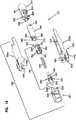
connector core 54 of the hardenedfiber optic connector 26 includes aferrule subassembly 70, anextension piece 72 and acable anchor 74. In certain examples, theextension piece 72 can be mounted between theferrule subassembly 70 and thecable anchor 74. In one example, theferrule subassembly 70 attaches to a front end of theextension piece 72 by a mechanical interface such as a snap-fit connection. It will be appreciated that thefiber optic cable 46 can be secured to thecable anchor 74. In certain examples, thestrength elements 52 and thejacket 50 can be adhesively secured within thecable anchor 74. Thecable anchor 74 can include interlock structures 78 (e.g., teeth, tabs, ribs, etc.) that interlock withmating structures 79 on theplug body 34 to assist in axially fixing thecable anchor 74 relative to theplug body 34. In certain examples, thecable anchor 74 can connect to a rear end of theextension piece 72 by a snap-fit connection or other type of mechanical interface. - Referring to
Figure 6 , theferrule subassembly 70 of theconnector core 54 includes theferrule 38, aferrule hub 80 coupled to theferrule 38, aferrule spring 82 and aspring retainer 84. In certain examples, thespring retainer 84 is configured to couple to theferrule hub 80 such that theferrule spring 82 is captured between thespring retainer 84 and theferrule hub 80. For example, theferrule hub 80 can includetabs 86 that fit within correspondingopenings 88 defined by thespring retainer 84. In certain examples, thetabs 86 fit within theopenings 88 by a snap-fit connection. In certain examples, thespring retainer 84 can include an open through-slot 89 that extends through the length of thespring retainer 84 and allows thespring retainer 84 to flex open to allow thetabs 86 to snap-fit within theopenings 88. Thespring retainer 84 is configured to allow theferrule spring 82 to be pre-compressed in an initial compressed state between theferrule hub 80 and the spring retainer 84 (i.e., the spring holder). In this way, theferrule spring 82 can be pre-compressed prior to loading theconnector core 54 into theplug body 34. In the initial compressed state, theferrule spring 82 is shorter than in the non-compressed state thereby allowing thepre-assembled ferrule subassembly 70 to be shorter. As described herein, shortening of theferrule subassembly 70 by pre-compressing theferrule spring 82 reduces the amount of excess fiber that must be pulled from the connector during the assembly process. - The
ferrule 38 and thecorresponding ferrule hub 80 move together as a unit relative to thespring retainer 84. Theferrule 38 and theferrune hub 80 can be referred to as aferrule unit 91. Theferrule spring 82 biases theferrule unit 91 in a forward direction relative to thespring retainer 84. The connection between thespring retainer 84 and theferrule hub 80 limits the range of axial movement that is permissible between the ferrule unit 91 (i.e., theferrule 38 and its corresponding ferrule hub 80) and thespring retainer 84. By precisely limiting the range of seal movement of theferrule unit 91 relative to thespring retainer 84, fiber buckling in the hardenedfiber optic connector 26 can be precisely predicted, limited and controlled. In certain examples, rearward movement of the ferrule unit relative to thespring retainer 84 is limited by interference between thetabs 86 and rear ends of theopenings 88. In other examples, rearward movement of the ferrule unit relative to thespring retainer 84 can be limited by contact between afront flange 92 of theferrule hub 80 and aforward end 94 of thespring retainer 84. - In certain examples, the
cable anchor 74 can be integrated directly into theextension piece 72 thereby allowing thestrength elements 52 to be coupled directly to theextension piece 72 without an intermediate cable anchor piece. - According to the invention, the
spring retainer 84 is coupled to theferrule hub 80 by a connection that allows theferrule unit 91 to slide axially relative to thespring retainer 84 along a limited range of movement defined between first and second axial positions. Theferrule spring 82 biases the ferrule unit toward the first axial position. The coupling between theferrule hub 80 and thespring retainer 84 can provide a positive stop that stops forward movement of theferrule unit 91 relative to thespring retainer 84 at the first axial position. The coupling between theferrule hub 80 and thespring retainer 84 can also provide a positive stop that stops rearward movement of the ferrule unit relative to thespring retainer 84 at the second axial position. In certain examples, the ferrule unit is rotationally keyed relative to thespring retainer 84 such that relative rotation between the ferrule unit and thespring retainer 84 is prevented. In one example, the first positive stop can be provided by contact between thetabs 86 and forward ends of theopenings 88. In certain examples, the second positive stop can be provided by contact between thefront flange 92 of theferrule hub 80 and theforward end 94 of thespring retainer 84. - Referring to
Figures 4 and 5 , theferrule 38 includes afront face 96 that can be polished. Anoptical fiber stub 98 is secured within a longitudinal bore of theferrule 38. Theoptical fiber stub 98 has afront end 100 positioned at thefront face 96 of theferrule 38 and arear end portion 102 that projects rearwardly from a rear end of theferrule 38. Therear end portion 102 of theoptical fiber stub 98 can be spliced to theoptical fiber 48 of thefiber optic cable 46 at asplice location 104. Thesplice location 104 can be protected within theferrule hub 80. In certain examples, theferrule hub 80 can include thefront flange 92 that is secured to theferrule 38 prior to splicing, and arear hub portion 106 that can be secured to the rear end of theferrule 38 after splicing. Therear hub portion 106 can include anouter shell 108 that abuts against a back side of thefront flange 92. Theouter shell 108 can include alongitudinal slot 110 that allows theouter shell 108 to be inserted over thesplice location 104 after splicing. Theouter shell 108 can define aport 112 for allowing asplice encapsulating material 113 such as adhesive to be injected into the interior of theouter shell 108 to encapsulate and protect thesplice location 104. Thetabs 86 for mechanically interfacing with thespring retainer 84 can be provided on theouter shell 108. - The
front flange 92 can be configured to mate with the interior of theplug body 34 so as to prevent relative rotation between theferrule hub 80 and theplug body 34. For example, thefront flange 92 can include a plurality offlats 114 that oppose corresponding flats defined within the interior of theplug body 34 so as to prevent relative rotation between theferrule hub 80 and theplug body 34. Additionally, thefront flange 92 can include frontangled surfaces 116 that preferably seat against corresponding surfaces defined within theplug end 36 of theplug body 34 when theconnector core 54 is loaded therein. - The
optical fiber 48 may be fixed relative to the hardenedfiber optic connector 26 by adhesive at thecable anchor 74. Thus, when theferrule 38 is pushed back relative to theplug body 34 when engaging the mating non-hardenedfiber optic connector 24 within thefiber optic adapter 22, theoptical fiber 48 is prevented from pushing back into thefiber optic cable 46. Thus, when the hardenedfiber optic connector 26 is connected with another connector, space should be provided within the hardenedfiber optic connector 26 to accommodate the associated fiber buckling that occurs. In the depicted example, this fiber buckling space is provided by theextension piece 72. Theextension piece 72 is elongated and extends a majority of the length of theplug body 34. Sufficient interior space is provided within theextension piece 72 to accommodate buckling associated with the rearward movement of theferrule 38 against the bias of theferrule spring 82 during connector coupling. As indicated previously, theferrule subassembly 70 is configured to precisely control the range of movement of theferrule 38 and provides positive stops for preventing theferrule 38 from being moved rearwardly beyond a predetermined limit. Therefore, the degree of buckling that is to be accommodated within theextension piece 72 is predetermined and controlled. - The
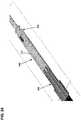
extension piece 72 also includes a mechanical interlock feature 120 (seeFig. 7 ) adapted to interlock or otherwise mechanically engage with theplug body 34. In the depicted example, theinterlock feature 120 includes a tab that fits within acorresponding opening 122 defined by the plug body 34 (seeFig. 9 ). - During assembly of the hardened
fiber optic connector 26, it will be appreciated that theconnector core 54 is preassembled prior to insertion within theplug body 34. As part of the preassembly process, theferrule subassembly 70 is preassembled and theferrule spring 82 is pre-compressed and retained in the initial compressed state by thespring retainer 84. When theconnector core 54 is loaded into theplug body 34, the frontangled surfaces 116 of theferrule hub 80 abut against the corresponding surfaces provided within theplug end 36 of theplug body 34 and a secondary compression force is applied to theferrule spring 82 as theconnector core 54 is loaded into theplug body 34. This secondary compression force is sufficient to move theferrule spring 82 from the initial compressed state to a final compressed state. In the final compressed state, the frontangled surfaces 116 are biased firmly against the corresponding angled surfaces at theplug end 36 of theplug body 34, and the ferrule unit is forced slightly rearwardly with respect to the forward positive stop position defined by the mechanical interface between theferrule hub 80 and thespring retainer 84. This secondary compression step assures that the frontangled surfaces 116 are properly seated against theplug end 36 of theplug body 34, and that any tolerances in the manufacturing process have been taken up. Theinterlock feature 120 and thecorresponding opening 122 are relatively positioned such that the mechanical interlock fixes theconnector core 54 in the appropriate axial position relative to theplug body 34 where theferrule spring 82 is secured and retained in the final compressed state. It will be appreciated that theplug body 34 generally defines the centrallongitudinal axis 41, and that axial movement referred to herein is made with reference to such a centrallongitudinal axis 41. - To assemble the hardened
fiber optic connector 26, thefiber optic cable 46 is initially prepared using stripping, cleaving and cleaning operations. As so prepared, an end portion of thejacket 50 is removed to expose theoptical fiber 48 and end portions of thestrength elements 52. After preparation of thefiber optic cable 46, thecable anchor 74 and theferrule spring 82 can be inserted over theoptical fiber 48 and theoptical fiber 48 can be fusion spliced to theoptical fiber stub 98 of theferrule 38 at the splice location 104 (seeFig. 4 ). After splicing, theouter shell 108 of theferrule hub 80 can be laterally inserted over thesplice location 104 and filled with adhesive or other encapsulatingmaterial 113 that encapsulates and protects the splice location 104 (seeFig. 5 ). Theferrule subassembly 70 is then assembled by sliding theferrule spring 82 forwardly into engagement with theferrule hub 80 and inserting thespring retainer 84 laterally over the splicedoptical fiber stub 98 andoptical fiber 48 via the through-slot 89 at a location behind theferrule spring 82. Thespring retainer 84 is then slid forwardly over therear hub portion 106 causing theferrule spring 82 to be axially compressed between thespring retainer 84 and theferrule hub 80. As previously indicated, the precompression of theferrule spring 82 causes theferrule spring 82 to be shortened and retained in an initial compressed state. Thespring retainer 84 is moved forwardly until thetabs 86 of theferrule hub 80 snap within theopenings 88 of thespring retainer 84 such that thespring retainer 84 is effectively coupled to theferrule hub 80. In this way, theferrule spring 82 is captured and retained in the initial compressed state by thespring retainer 84 via its coupling to theferrule hub 80.Figure 6 shows thepreassembled ferrule subassembly 70. - After preassembling the
ferrule subassembly 70, theextension piece 72 is installed between thespring retainer 84 and thecable anchor 74. Snap-fit connections may be provided between thespring retainer 84 and the front end of theextension piece 72 and between thecable anchor 74 and the rear end of theextension piece 72.Figure 7 shows thepre-assembled connector core 54 prior to insertion within theplug body 34. After theconnector core 54 has been preassembled, the connector core is inserted axially into theplug body 34 as shown atFigure 7 . Theconnector core 54 is inserted axially into theplug body 34 until the frontangled surfaces 116 at the front side of theferrule hub 80 engage a stop structure at the inside of theplug end 36 of theplug body 34 and sufficient axial pressure is applied to theconnector core 54 to move theferrule spring 82 from the initial compressed state to a final compressed state. It will be appreciated that theinterlock feature 120 of theconnector core 54 snaps within theopening 122 of theplug body 34 when theconnector core 54 has been inserted sufficiently within theplug body 34 for theferrule spring 82 to move from the initial compressed state to the final compressed state. Thus, theinterlock feature 120 and theopening 122 function to secure theconnector core 54 and itscorresponding ferrule subassembly 70 in an axial position relative to theplug body 34 where theferrule spring 82 is retained in the final compressed state.Figures 8 and9 show theconnector core 54 fully loaded within theplug body 34. - Once the
connector core 54 has been loaded within theplug body 34, the assembly can be loaded into afixture 130 having afirst portion 132 that engages a forward portion of theplug body 34 and asecond portion 134 that can attach (e.g., clamp) to thefiber optic cable 46. Aspring 136 can be provided between the first andsecond portions second portion 134 that biases thesecond portion 134 in a rearward direction relative to thefirst portion 132. In this way, thefiber optic cable 46 is pulled rearwardly relative to theplug body 34 to cause any excess fiber length within theconnector core 54 to be taken up. In certain examples, thespring 136 has a spring force that is equal to or less than a corresponding spring force of theferrule spring 82. In this way, further compressive load is not applied to theferrule spring 82 which would cause theferrule spring 82 to apply tension to theoptical fiber 48. Once any slack optical fiber has been straightened within theconnector core 54, adhesive material such as epoxy can be injected into thecable anchor 74 to secure thestrength elements 52 and thus thefiber optic cable 46 at the set axial position relative to theplug body 34 where excess fiber length is not provided within theconnector core 54. After curing of the adhesive, the assembly can be removed from thefixture 130 and the remainder of the assembly process can take place. For example, side cover 60 of theplug body 34 can be installed on themain body 58 of theplug body 34. Also, theshape memory sleeve 64 can be slid over the rear portion of theplug body 34, the heat shrink can be applied over the interface between the hardenedfiber optic connector 26 and thefiber optic cable 46, thefastening element 40 can be slid over themetal sleeve 62 and theboot 66 can be installed at the rear of theplug body 34. It will be appreciated that prior to the splicing step, components such as theboot 66, theshape memory sleeve 64, andmetal sleeve 62 and thefastening element 40 can be slid over thefiber optic cable 46. - A typical single fiber optical connector includes a ferrule having an outer cylindrical surface that functions as a reference surface when the ferrule is received within an alignment sleeve of a fiber optic adapter. The ferrule also defines a central axial passageway in which the optical fiber is secured. Ideally, the optical fiber is secured in the central axial passageway with the fiber core perfectly concentric with the outer cylindrical surface of the ferrule. However, due to manufacturing tolerances, the fiber core is not typically perfectly concentric with the outer cylindrical surface. This is because, among other things, the ferrule passageway may not be concentric with the ferrule outer cylindrical surface, the optical fiber may not be centered in the ferrule passageway, and the fiber core may not be centered within the fiber cladding that defines an outer surface of the optical fiber. This lack of concentricity between the fiber core and the ferrule outer cylindrical surface causes fiber core eccentricity. Fiber core eccentricity can be defined as the distance between the central longitudinal axis of the fiber core (i.e., the fiber core axis) and the central longitudinal axis defined by the ferrule outer cylindrical surface (i.e., the ferrule axis). The direction that the fiber core axis is offset from the ferrule axis can be referred to as the direction of core eccentricity.
FIG. 11 shows an end view of aferrule 220 holding anoptical fiber 221 having afiber core 222 and acladding 224. Thecladding 224 typically has a different index of refraction as compared to thefiber core 222 so that light transmitted through theoptical fiber 221 can be contained generally within thefiber core 222 by total internal reflection. Thefiber core 222 is not centered relative to an outer cylindrical surface of theferrule 220. Rather, a fiber core axis AC of thefiber core 222 is offset from a central longitudinal axis AF of theferrule 220. In the example shown, the fiber core axis AC is offset upwardly relative to the outer cylindrical surface of theferrule 220. In other examples, the fiber core axis AC can be offset in any other direction relative to the outer cylindrical surface of theferrule 220. The distance EC by which the fiber core axis AC is offset from the central longitudinal axis AF of theferrule 220 corresponds to the fiber core eccentricity and is exaggerated for the purpose of illustration.. Other fiber core eccentricities can occur due to the fiber being offset within the opening of the ferrule, even if it is centrally located in the ferrule, and/or if the core is not concentric with the cladding of the fiber.- Due to fiber core eccentricity, signal losses within a system can occur at the connection between two optical fibers. This is because fiber core eccentricity prevents the fiber cores of the optical fibers being optically coupled together from being perfectly co-axially aligned. The worst-case scenario occurs when the ferrules of two fiber optic connectors being coupled together have directions of core eccentricity that are 180 degrees out of phase with respect to each other. To minimize the negative effect of fiber core eccentricity with respect to signal loss, it is desirable to position the directions of core eccentricity of the ferrules of fiber optic connectors being coupled together in the same rotational orientation. This can be accomplished by "tuning" fiber optic connectors during manufacturing such that the direction of core eccentricity is the same for all of the fiber optic connectors. Tuning typically involves rotating the ferrule to intentionally position the direction of core eccentricity of the ferrule at a particular rotational orientation relative to one or more keyed components of the fiber optic connector. Example tuning techniques are disclosed at
PCT Publication No. WO 02/052310 U.S. Patent No. 5,212,752 ). - It will be appreciated that the hardened
fiber optic connector 26 is depicted as a splice-on fiber optic connector. As previously described, theferrule 38 supports theoptical fiber stub 98 that is spliced to theoptical fiber 48 of thefiber optic cable 46. Prior to splicing, thefront end 100 of theoptical fiber stub 98 as well as thefront face 96 of theferrule 38 can be pre-processed using processing techniques such as polishing, cleaving, shaping, laser processing or other processing techniques. Additionally, prior to splicing, a direction of core eccentricity of theoptical fiber stub 98 relative to theferrule 38 can be determined and marked on theferrule 38 or thefront flange 92 of the ferrule hub. Thus, at the time of splicing, the direction of core eccentricity of the ferrule assembly can be taken into consideration. For example, tuning can be accomplished by orienting the direction of core eccentricity at a particular rotational orientation relative to thefiber optic cable 46 prior to splicing. The direction of core eccentricity can also be oriented at a particular orientation relative to theplug body 34 prior to splicing. In this way, after splicing, the hardenedfiber optic connector 26 is tuned such that the core offset is oriented in a desired rotational orientation about the central longitudinal axis of theferrule 38. FIGS. 12 and13 depict another hardenedfiber optic connector 310. The hardenedfiber optic connector 310 is shown terminating afiber optic cable 312 having anoptical fiber 314 andstrength members 316 surrounded by ajacket 315. As shown atFIG. 14 , theoptical fiber 314 can include acore 307 surrounded by acladding layer 309. A loose ortight buffer 305 can be provided between theoptical fiber 314 and thestrength members 316. The hardenedfiber optic connector 310 includes astrain relief boot 311 that extends over thefiber optic cable 312. Thestrain relief boot 311 couples to anouter shroud 317 disposed about an inner arrangement 313 (FIG. 13 ) including a tunable connector core 321 (seeFIGS. 16 ,18 ,20 and24 ) that mounts within aplug body 360. Arobust fastening element 319 mounts over theshroud 317 and can be rotated relative to theouter shroud 317 about a central longitudinal axis of the hardenedfiber optic connector 310. In one example, the hardenedfiber optic connector 310 directly terminates theoptical fiber 314 of thefiber optic cable 312 without any intermediate splices. A tuning feature is integrated into thetunable connector core 321 to allow the hardenedfiber optic connector 310 to be readily tuned (i.e., the fiber core eccentricity of the ferrule can be set at a desired rotational orientation relative to a keyed component of the connector such as the shroud, the plug body or both) after mounting on theoptical fiber 314 to provide enhanced performance (e.g., low insertion loss).- The
outer shroud 317 has akeying feature 318 that ensures the hardenedfiber optic connector 310 is loaded into a mating connecting component (e.g., a mating fiber optic adapter or a mating fiber optic connector) at a particular rotational orientation.FIG. 15 shows an example matingfiber optic adapter 349. In the depicted example, the keyingfeature 318 is shown as a female structure such as a notch/slot adapted to mate with a corresponding male feature (e.g., a key, rail, projection, tab, etc.) of the mating fiber optic adapter. In other example, the keyingfeature 318 can include a male structure (e.g., one or more tabs, keys, rails, projections, etc.) that mates with a corresponding female structure of the mating fiber optic adapter. - The
robust fastening element 319 of the hardenedfiber optic connector 310 is configured for mechanically coupling the hardenedfiber optic connector 310 to its correspondingfiber optic adapter 349. In certain examples, thefastening element 319 mounts over theouter shroud 317 and is free to rotate about theouter shroud 317. In the depicted example, therobust fastening element 319 includes coupling nut having external threads adapted to engage internal threads of the mating fiber optic adapter. In other examples, the fastening element can include a coupling sleeve having internal threads that engage external threads of the mating fiber optic adapter. In other examples, the robust coupling can be provided by a bayonet-style coupling arrangement between the fastening element and the mating fiber optic adapter. It will further be appreciated that the interface between the hardenedfiber optic connector 310 and its mating fiber optic adapter is preferably environmentally sealed by a sealing arrangement to limit or prevent the intrusion of moisture, dust or other contaminants. The sealing arrangement can include one or more sealing members (e.g., o-rings, radial seals, face seals, or other gasket-type seals) mounted on the shroud, on the connector plug body or on/in the fiber optic adapter. - As shown at
FIGS. 16 ,18 and20 , thetunable connector core 321 of the hardenedfiber optic connector 310 includes acable anchor 320 coupled to aferrule subassembly 381 by an elongated extension piece 340 (e.g., an extension tube). Theferrule subassembly 381 includes a ferrule 71 in which theoptical fiber 314 is secured (e.g., an end portion of theoptical fiber 314 can be secured by adhesive within the ferrule 371). Theferrule subassembly 381 also includes aferrule hub 380 secured to theferule 371, aferrule spring 395 and aspring retainer 350 that couples to theferrule hub 380. Thespring retainer 350 couples to theferrule hub 380 and theferrule spring 395 is captured between theferrule hub 380 and thespring retainer 350. In this way, theferrule spring 395 is pre-compressed between thespring retainer 350 and theferrule hub 380. Thus, similar to previously described examples, the configuration of theferrule subassembly 381 allows theferrule spring 395 to be pre-compressed to an initial compressed state prior to loading theferrule subassembly 381 into theplug body 360. As previously described, this assists in facilitating assembly operations and also allows the amount excess fiber length that must be accounted for during assembly to be reduced thereby allowing for shortening of the overall length of the fiber optic connector. - The
spring retainer 350 is configured to couple to a front end of the extension piece 340 (e.g., by a snap-fit connection or other type of mechanical connection). The hardenedfiber optic connector 310 also includes theplug body 360 that fits over thetunable connector core 321. Theplug body 360 includes afront plug portion 361 in which theferule subassembly 381 is received, and arear portion 363 that couples to thefront plug portion 361. Therear portion 363 includesmating pieces extension piece 340 and thecable anchor 320 and that fix thefront plug portion 361 relative to thecable anchor 320. Themating pieces front plug portion 361 in position over theferrule subassembly 381. Theouter shroud 317 fits over theplug body 360. Thecable anchor 320 is configured to couple to a rear end of the extension piece 340 (e.g., by a snap-fit connection or other type of mechanical connection). - The
cable anchor 320 can be filled with adhesive (e.g., epoxy) viaport 421 and functions to anchor thecable strength members 316 of thefiber optic cable 312 to thetunable connector core 321 and also serves as an axial fixation location for theoptical fiber 314 of thefiber optic cable 312. Theoptical fiber 314 can be pulled back away fromferrule subassembly 381 before applying the epoxy or before the epoxy cures to remove excess fiber length from within thetunable connector core 321. - The
extension piece 340 provides space for allowing theoptical fiber 314 to buckle when theferrule 371 is pushed back in direction 372 (FIG. 12 ) when the hardenedfiber optic connector 310 is coupled to another connector. In one example, the rear end of theextension piece 340 connects to the front end of thecable anchor 320 by a snap fit connection. In certain implementations,tabs 398 of thecable anchor 320 snap withinopenings 397 of the extension piece 340 (seeFIGS. 16 and20A ). Theextension piece 340 can include a full lengthlongitudinal slot 373. Theextension piece 340 can be added to thetunable cable core 321 after placement of thecable anchor 320 on thefiber optic cable 312 and after theoptical fiber 314 has been secured to theferrule 371 and the end face of theferrule 371 has been processed (e.g., polished). Thelongitudinal slot 373 allows theextension piece 340 to be laterally inserted over theoptical fiber 314. - The
ferrule 371 and theferrule hub 380 form aferrule unit 370 that is biased forwardly relative to thespring retainer 350 by theferrule spring 395. Theferrule hub 380 includes a notchedcircumferential flange 391 andtabs 390. Thespring 395 is loaded into an interior 351 of thespring retainer 350 and is held therein by theferrule unit 370. For example, theferrule spring 395 can be captured between thetabs 390 of theferrule unit 370 and an annularspring engagement shoulder 352 of thespring retainer 350 as shown inFIG. 20B . When assembled, thetabs 390 fit within axiallyelongated slots 392 of thespring retainer 350 to secure theferrule unit 370 to the spring retainer 350 (seeFIG. 20B ). Thespring 395 biases theferrule unit 370 in a forward direction 374 (FIG. 12 ) and thetabs 390 can slide along theelongated slots 392 to allow relative axial movement between theferrule unit 370 and thespring retainer 350. - The
elongated slots 392 of thespring retainer 350 are defined withinflexible arms 354 that flex apart to accommodate thetabs 390 during assembly of theferrule subassembly 381. The rear end of thespring retainer 350 can attach to the front end of theextension piece 340 by a snap-fit connection or other type of mechanical connection. For example,tabs 396 of theextension piece 340 can snap withinopenings 394 of the spring retainer 350 (seeFIGS. 16 and20B ). Thespring retainer 350 and thus theentire ferrule subassembly 381 can be rotated relative to theextension piece 340 about a central longitudinal axis of theferrule 371 to position a core eccentricity of theoptical fiber 314 within theferrule 371 at a desired rotational position (e.g., a rotational position that aligns with a key of the hardenedfiber optic connector 310 or other rotational position). In the example shown, theextension piece 340 has sixtabs 396 and theextension piece 340 has sixcorresponding openings 394 that enable theferrule subassembly 381 to be rotated relative to theextension piece 340 to six different rotational tuning positions to tune the hardenedfiber optic connector 310. In some examples, theferrule subassembly 381 can be initially rotated to the desired tuned rotational position and then connected to theextension piece 340 while being pre-oriented at the desired tuned rotational position. In other examples, theferrule subassembly 381 can be initially connected to theextension piece 340 and then rotated to the desired tuned rotational position after connection to theextension piece 340. - The
front plug portion 361 fits over theferrule subassembly 381 after theferrule subassembly 381 has been rotated to the desired tuned position.Rails 365 within thefront plug portion 361 fit withinnotches 401 of the notchedcircumferential flange 391 to further prevent relative rotation between theferrule subassembly 381 and thefront plug portion 361 once theplug body 360 has been installed over the tunable connector core 321(seeFIGS. 20B and21 ). Angled front surfaces 520 (seeFIGS. 16 and18A ) of theferrule hub 380 are preferably spring biased against corresponding angled shoulder surfaces 521 (seeFIG. 18A ) within thefront plug portion 361. The angled shoulder surfaces 521 form a seat within the front plug portion against which the angled front surfaces 520 at the front of theferrule hub 380 are spring biased. - The
mating pieces rear portion 363 of theplug body 360 couple thefront plug portion 361 to thecable anchor 320. Therear portion 363 is rotationally keyed and axially fixed relative to thecable anchor 320. In certain implementations, thecable anchor 320 includesprojections 323, 324 (FIGS. 16 ,18B and20A ) that fit withinreceptacles mating pieces FIGS. 16 ,18B , and20A ). Theprojections receptacles connector core 321 into theplug body 360, the angled front surfaces 520 of theferrule hub 380 are forced against the angled shoulder surfaces 521 causing further compression of theferrule spring 395 from the initial pre-compressed state to a final compressed state. In this way, mechanical tolerances are accounted for thereby ensuring that the angled front surfaces 520 seat against the angled shoulder surfaces 521. - The
front plug portion 361 is rotationally keyed and axially fixed relative to themating pieces rear portion 363. For example, tabs 500 (FIGS. 16 and20B ) on themating pieces FIGS. 16 and20B ) defined in the front plug portion 363 (seeFIG. 20B ). Rails 504 (FIGS. 16 and18A ) of themating pieces FIGS. 16 and18A ) defined in the front plug portion 361 (seeFIG. 18A ). Aback end 508 of thefront plug portion 361 has a square transvers cross-sectional shape and fits within asquare receptacle 509 of therear portion 363 to further rotationally key and axially fix thefront plug portion 361 relative to therear portion 363 of theplug body 360. - The
outer shroud 317 mounts over theplug body 360. Therear portion 363 of theplug body 360 is rotationally keyed relative to theouter shroud 317 by opposingflats plug body 360 and the outer shroud 317 (seeFIG. 22 ). - The
longitudinal slot 373 defined through the entire length of theextension piece 340 allows it to be added, or removed, if desired. One advantage of making thespring retainer 350 and theextension piece 340 separate pieces is that theextension piece 340 can be added to thetunable connector core 321 after theferrule subassembly 381 has been fully assembled, theoptical fiber 314 has been secured in theferrule 371, and the end face of theoptical fiber 314 has been fully processed (e.g., polished, laser treated, laser cleaved, etc.). In this way, extra fiber length is made available to facilitate using the fiber processing equipment and enhancing fiber processing operations. The final fiber length within the connector is established by assembling the connector, pulling the rearwardly cable to a desired position, then anchoring the cable strength members and the cable fiber within the cable anchor with epoxy injected in the cable anchor. - In terminating the
fiber optic cable 312 with the hardenedfiber optic connector 310, the end of thefiber optic cable 312 is first prepared by stripping the outer jacket to expose the optical fiber and strength members, and by cleaving and stripping the optical fiber as needed. Theferrule assembly 381 is pre-assembled thereby pre-compressing theferrule spring 395 between theferrule hub 380 and thespring retainer 350. Thestrain relief boot 311, therobust fastening element 319 and theouter shroud 317 can be slid over thecable jacket 315. Thecable anchor 320 is inserted over the exposedoptical fiber 314 and thestrength members 316 and a portion of thejacket 315 of thefiber optic cable 312 are positioned within thecable anchor 320. The end of theoptical fiber 314 then is secured within theferrule 371 of the pre-assembled ferrule subassembly 381 (seeFIG. 23 ). The end faces of theferrule 371 and theoptical fiber 314 are then polished or otherwise processed to angle, shape and/or remove imperfections from the end face of theoptical fiber 314. After fiber processing, a direction of core eccentricity of the fiber core relative to theferrule 371 is determined and marked on theferrule 371 orferrule hub 380 to provide an indication of core eccentricity. Theextension piece 340 is then inserted laterally over theoptical fiber 314 and is mounted between thecable anchor 320 and theferrule subassembly 381 to complete assembly of the connector core 321(seeFIG. 24 ). Theferrule subassembly 381 is then rotated as needed relative to theextension piece 340 generally about a central longitudinal axis of theferrule 371 to move the direction of core eccentricity to a tuned rotational position relative to thecable anchor 320. Because thecable anchor 320 is rotationally keyed relative to theplug body 360, tuning relative to thecable anchor 320 provides tuning relative to theplug body 360. After tuning, thefiber optic cable 312 can be pulled rearwardly relative to the assembledtunable connector core 321 to remove excess optical fiber from within theextension piece 340. Once the excess optical fiber has been removed, adhesive can be injected into thecable anchor 320 to anchor the fiber optic cable 312 (e.g., thestrength members 316 and the jacket 315) relative to thetunable connector core 321 and to provide an axial fixation location for theoptical fiber 314. - After curing of the adhesive, the
tunable connector core 321 is loaded into theplug body 360. In one example, one of themating pieces front plug portion 361. The front end of theconnector core 321 is then inserted intofront plug portion 361 through the back end of thefront plug portion 361. Insertion continues causing the angled front surfaces 520 of theferrule hub 380 to abut against the angled shoulder surfaces 521 within thefront plug portion 361. Insertion continues after contact between thesurfaces ferrule spring 395. Insertion continues further until theprojections receptacles mating piece tunable connector core 321 in axial position relative to theplug body 360. Theother mating piece inner arrangement 313. Finally, theouter shroud 317 can be slid over theinner arrangement 313, sealing can be provided between theouter shroud 317 and the fiber optic cable 312 (e.g., with a heat shrink sleeve pre-loaded over the cable), therobust fastening element 319 can be slid over theouter shroud 317 and thestrain relief boot 311 can be mounted to the rear end of theouter shroud 317. - The
fiber optic connector 310 may be a hardened connector. For example, the hardenedfiber optic connector 310 may also include one or more environmental seals for providing a sealed interface with an adapter port. As noted above, the hardenedfiber optic connector 310 may also include arobust fastening element 319, such as a threaded member or a bayonet style fastener, for securing theconnector 310 in the adapter port. - The tunable connector core can be used in combination with other types of plug bodies. For example, the tunable connector core can be used in combination with the
plug body 34 ofFIG. 3 . - 20
- hardened fiber optic connection system
- 22
- fiber optic adapter
- 24
- non-hardened fiber optic connector
- 26
- hardened fiber optic connector
- 28
- first port
- 30
- second port
- 32
- seal
- 34
- plug body
- 36
- plug end
- 38
- ferrule
- 40
- fastening element
- 41
- central longitudinal axis
- 42
- threads
- 44
- corresponding threads
- 46
- fiber optic cable
- 48
- optical fiber
- 50
- jacket
- 52
- strength elements
- 54
- connector core
- 56
- dust cap
- 58
- main body
- 60
- side cover
- 62
- metal sleeve
- 64
- shape memory sleeve
- 66
- boot
- 68
- lanyard
- 70
- ferrule subassembly
- 71
- ferrule
- 72
- extension piece
- 74
- cable anchor
- 78
- interlock structures
- 79
- mating structures
- 80
- ferrule hub
- 82
- ferrule spring
- 84
- spring retainer
- 86
- tabs
- 88
- openings
- 89
- open through-slot
- 91
- ferrule unit
- 92
- front flange
- 94
- forward end
- 96
- front face
- 98
- optical fiber stub
- 100
- front end
- 102
- rear end portion
- 104
- splice location
- 106
- rear hub portion
- 108
- outer shell
- 110
- longitudinal slot
- 112
- port
- 113
- splice encapsulating material
- 114
- flats
- 116
- front angled surfaces
- 120
- interlock feature
- 122
- opening
- 130
- fixture
- 132
- first portion
- 134
- second portion
- 136
- spring
- 220
- ferrule
- 221
- optical fiber
- 222
- fiber core
- 224
- cladding
- 305
- loose or tight buffer
- 307
- core
- 309
- cladding layer
- 310
- hardened fiber optic connector
- 311
- strain relief boot
- 312
- fiber optic cable
- 313
- inner arrangement
- 314
- optical fiber
- 315
- jacket
- 316
- strength members
- 317
- outer shroud
- 318
- keying feature
- 319
- robust fastening element
- 320
- cable anchor
- 321
- tunable connector core
- 323,324
- projections
- 325,326
- receptacles
- 330a, 330b
- mating pieces
- 340
- elongated extension piece
- 349
- mating fiber optic adapter
- 350
- spring retainer
- 351
- interior
- 352
- spring engagement shoulder
- 354
- flexible arms
- 360
- plug body
- 361
- front plug portion
- 363
- rear portion
- 365
- rails
- 370
- ferrule unit
- 371
- ferrule
- 372
- direction
- 373
- longitudinal slot
- 374
- forward direction
- 380
- ferrule hub
- 381
- ferrule subassembly
- 390
- tabs
- 391
- circumferential flange
- 392
- elongated slots
- 394
- openings
- 395
- ferrule spring
- 396
- tabs
- 397
- openings
- 398
- tabs
- 401
- notches
- 410, 411
- opposing flats
- 421
- port
- 500
- tabs
- 502
- openings
- 504
- rails
- 506
- slots
- 508
- back end
- 509
- square receptacle
- 520
- angled front surfaces
- 521
- angled shoulder surfaces
Claims (19)
- A method for assembling a fiber optic connector (26), the fiber optic connector (26) including a ferrule subassembly (70) including a ferrule (38), a ferrule hub (80) that attaches to the ferrule (38), a spring holder (84) and a connector spring (82), the fiber optic connector (26) including a plug body (34) in which the ferrule subassembly (70) mounts, the plug body (34) having a plug end (36) through which the ferrule (38) extends when the ferrule subassembly (70) is mounted within the plug body (34), the plug body (34) defining a central longitudinal axis, the method comprising:pre-assembling the ferrule subassembly (70) such that the connector spring (82) is pre-compressed in an initial compressed state between the ferrule hub (80) and the spring holder (84);coupling the spring holder (84) to the ferrule hub (80) by a connection that allows the ferrule (38) and the ferrule hub (80) to slide axially relative to the spring holder (84) along a limited range of movement defined between first and second axial positions;loading the pre-assembled ferrule subassembly (70) into the plug body (34) and applying a secondary compression force to the connector spring (82) as the pre-assembled ferrule assembly (70) is loaded into the plug body (34) to move the connector spring (82) to a final compressed state; andsecuring the ferrule subassembly (70) in axial position relative to the plug body (34) to retain the connector spring (82) in the final compressed state.
- The method of claim 1, wherein the ferrule subassembly (70) is incorporated into a connector core (54), and wherein the ferrule subassembly (70) is secured in axial position relative to the plug body (34) by mechanically interlocking the connector core (54) with the plug body (34).
- The method of claim 2, wherein the fiber optic connector (26) is adapted to be secured to an end of a fiber optic cable (46), wherein the fiber optic cable (46) includes an optical fiber (48) coupled with the ferrule (38), wherein the connector core (54) includes a cable anchor (74) to which a strength member (52) of the fiber optic cable (46) is secured, and wherein prior to securing the strength member (52) of the cable (46) to the cable anchor (74), the cable (46) is pulled back relative to the connector core (54) to remove excess length of the optical fiber (48) from within the connector core (54).
- The method of claim 3, wherein the cable (46) is pulled back with a force less than or equal to a spring force of the connector spring (82).
- The method of claim 3, wherein the fiber optic connector (26) is assembled on a fixture (130), and wherein the fixture (130) includes a fixture spring (136) for pulling back the fiber optic cable (46) relative to the cable core.
- The method of claim 5, wherein the fixture spring (36) has a spring force less than or equal to a spring force of the connector spring (82).
- The method of claim 3, wherein a stub optical fiber (98) is secured within the ferrule (38), and wherein the optical fiber (48) of the fiber optic cable (46) is spliced to the stub optical fiber (98).
- The method of claim 7, wherein the fiber optic connector (26) is tuned by rotationally orienting the ferrule (38) at a desired rotational orientation prior to splicing the stub optical fiber (98) to the optical fiber (48) of the fiber optic cable (46).
- The method of claim 8, further comprising encasing the splice in an adhesive filled shell after splicing, the adhesive filled shell forming a part of the ferrule hub (80).
- The method of claim 3, wherein the ferrule subassembly (70) can be rotated relative to a remainder of the connector core (54) to tune the fiber optic connector (26).
- A fiber optic connector (26) comprising:a plug body (34) having a plug end (36);a connector core (54) that mounts within the plug body (34), the connector core (54) including a ferrule subassembly (70) the ferrule subassembly (70) including a ferrule (38), a ferrule hub (80) that attaches to the ferrule (38), a spring holder (84) and a connector spring (82), wherein the spring holder (84) is coupled to the ferrule hub (80) by a connection that allows the ferrule (38) and the ferrule hub (80) to slide axially relative to the spring holder (84) along a limited range of movement defined between first and second axial positions and allowing the ferrule sub-assembly (70) to be assembled with the connector spring pre-compressed to an initial compressed state prior to mounting the connector core (54) within the plug body; andwherein the plug body (34) and the core are configured such that the connector spring (82) is moved from the initial compressed state to a final compressed state when the connector core is loaded in the plug body (34).
- The fiber optic connector of claim 11, wherein the connector core (54) interlocks with the plug body (34) to retain the spring in the final compressed state.
- The fiber optic connector of claim 11, wherein the connector core (54) includes an extension piece (72), and wherein the ferrule subassembly (70) mounts to one end of the extension piece (72).
- The fiber optic connector of claim 13, wherein a cable anchor (74) mounts to an opposite end of the extension piece (72).
- The fiber optic connector of claim 13, wherein the ferrule subassembly (70) is mountable in a plurality of different rotational positions relative to the extension piece (72) to allow for tuning of the fiber optic connector (26).
- The fiber optic connector of claim 11, wherein the connector spring (82) biases the ferrule hub (80) toward the first axial position, and the coupling between the ferrule hub (80) and the spring holder (84) provides a positive stop that stops forward movement of the ferrule hub (80) relative to the spring holder (84) at the first axial position.
- The fiber optic connector of claim 16, wherein the coupling between the ferrule hub (80) and the spring holder (84) provides a positive stop that stops rearward movement of the ferrule hub (80) relative to the spring holder (84) at the second axial position.
- The fiber optic connector of claim 17, wherein the first positive stop is provided by contact between tabs (86) on the ferrule hub (80) and forward ends of openings (88) defined by the spring holder (84).
- The fiber optic connector of claim 18, wherein the second positive stop is provided by contact between a front flange (92) of the ferrule hub (80) and a forward end (94) of the spring holder (84).
Applications Claiming Priority (1)
| Application Number | Priority Date | Filing Date | Title |
|---|---|---|---|
| PCT/CN2014/094391WO2016095213A1 (en) | 2014-12-19 | 2014-12-19 | Hardened fiber optic connector with pre-compressed spring |
Publications (3)
| Publication Number | Publication Date |
|---|---|
| EP3234672A1 EP3234672A1 (en) | 2017-10-25 |
| EP3234672A4 EP3234672A4 (en) | 2018-08-22 |
| EP3234672B1true EP3234672B1 (en) | 2021-09-08 |
Family
ID=56125673
Family Applications (1)
| Application Number | Title | Priority Date | Filing Date |
|---|---|---|---|
| EP14908248.9AActiveEP3234672B1 (en) | 2014-12-19 | 2014-12-19 | Hardened fiber optic connector with pre-compressed spring |
Country Status (3)
| Country | Link |
|---|---|
| US (3) | US10180541B2 (en) |
| EP (1) | EP3234672B1 (en) |
| WO (1) | WO2016095213A1 (en) |
Families Citing this family (64)
| Publication number | Priority date | Publication date | Assignee | Title |
|---|---|---|---|---|
| EP2302431B1 (en)* | 2009-09-28 | 2019-03-27 | TE Connectivity Nederland B.V. | Sealing enclosure for a connector on a cable, such as a standardised fibre-optic connector |
| US10215926B2 (en) | 2011-12-14 | 2019-02-26 | Commscope Technologies Llc | Multi-fiber fiber optic connection system with flexible, insertable pins |
| WO2016087449A1 (en)* | 2014-12-01 | 2016-06-09 | Commscope Asia Holdings B.V. | Multi-fiber optic connector with pivotally-aligned ferrule |
| WO2016095213A1 (en)* | 2014-12-19 | 2016-06-23 | Tyco Electronics (Shanghai) Co., Ltd. | Hardened fiber optic connector with pre-compressed spring |
| US9448365B2 (en)* | 2014-12-31 | 2016-09-20 | Commscope, Inc. Of North Carolina | Trunk gland adapters and related trunk gland units and methods of connecting trunk cables to fiber optic enclosures |
| EP3311207A4 (en) | 2015-06-19 | 2019-02-20 | Commscope Technologies LLC | Fiber optic connector ferrule with improved alignment mechanism |
| ES2738423T3 (en)* | 2015-06-30 | 2020-01-22 | Corning Optical Communications LLC | Fiber optic cable assembly |
| US10782484B2 (en)* | 2016-06-20 | 2020-09-22 | Commscope Technologies Llc | Ferrule-less fiber optic connector |
| US11300746B2 (en) | 2017-06-28 | 2022-04-12 | Corning Research & Development Corporation | Fiber optic port module inserts, assemblies and methods of making the same |
| US11187859B2 (en) | 2017-06-28 | 2021-11-30 | Corning Research & Development Corporation | Fiber optic connectors and methods of making the same |
| US10359577B2 (en) | 2017-06-28 | 2019-07-23 | Corning Research & Development Corporation | Multiports and optical connectors with rotationally discrete locking and keying features |
| CN111051945B (en) | 2017-06-28 | 2023-12-29 | 康宁研究与开发公司 | Compact fiber optic connector, cable assembly and method of making the same |
| US12271040B2 (en) | 2017-06-28 | 2025-04-08 | Corning Research & Development Corporation | Fiber optic extender ports, assemblies and methods of making the same |
| US11668890B2 (en) | 2017-06-28 | 2023-06-06 | Corning Research & Development Corporation | Multiports and other devices having optical connection ports with securing features and methods of making the same |
| USD1002540S1 (en)* | 2017-11-30 | 2023-10-24 | Corning Research & Development Corporation | Connector for making optical connections |
| US10324262B1 (en)* | 2017-12-07 | 2019-06-18 | Wei Min Wang | Field terminable fiber optic connectors |
| DE102018101431A1 (en)* | 2018-01-23 | 2019-07-25 | Neutrik Ag | connector |
| WO2019173350A1 (en)* | 2018-03-06 | 2019-09-12 | Commscope Technologies Llc | Modular hardened optical fiber connector and assembly method thereof |
| CA3095881A1 (en) | 2018-04-02 | 2019-10-10 | Senko Advanced Components, Inc | Hybrid ingress protected connector and adapter assembly |
| CN108459380B (en)* | 2018-04-27 | 2023-09-26 | 长飞光纤光缆股份有限公司 | Waterproof optical fiber connector |
| US10948664B2 (en) | 2018-05-08 | 2021-03-16 | Senko Advanced Components, Inc. | Ingress protected optical fiber connector having a reduced diameter with a removable retaining nut |
| US11409054B2 (en)* | 2018-05-11 | 2022-08-09 | Us Conec Ltd. | Method and apparatus for assembling uniboot fiber optic connectors |
| US11092756B2 (en) | 2018-10-10 | 2021-08-17 | Senko Advanced Components, Inc. | Ingress protected connector with an unitary orientation feature |
| US10976502B2 (en) | 2018-10-11 | 2021-04-13 | Seniko Advanced Components, Inc. | Outdoor rated assembly configured to blind mate opposing fiber optic connectors therein with a safety spring assembly |
| US11016247B2 (en) | 2018-10-11 | 2021-05-25 | Senko Advanced Components Inc | Mechanical splice protective sleeve for securing a splice area formed by splicing a plural of optical fibers |
| US10641967B1 (en) | 2018-11-16 | 2020-05-05 | Corning Research & Development Corporation | Multiport assemblies including a modular adapter support array |
| US10768382B2 (en) | 2018-11-29 | 2020-09-08 | Corning Research & Development Corporation | Multiport assemblies including access apertures and a release tool |
| US10761288B2 (en)* | 2018-12-06 | 2020-09-01 | Ofs Fitel, Llc | Armored fiber optic cable connector assembly |
| GB2579658A (en)* | 2018-12-11 | 2020-07-01 | Secr Defence | Fibre optic connector |
| PT3903136T (en) | 2018-12-28 | 2024-12-05 | Corning Res & Dev Corp | Multiport assemblies including mounting features or dust plugs |
| US11307359B2 (en) | 2019-02-07 | 2022-04-19 | Senko Advanced Components, Inc. | Ingress protected, outdoor rated connector with integrated optical connector plug frame |
| US11921329B2 (en) | 2019-02-12 | 2024-03-05 | Commscope Technologies Llc | Fiber optic connectors and fiber optic connection systems |
| WO2020242847A1 (en) | 2019-05-31 | 2020-12-03 | Corning Research & Development Corporation | Multiports and other devices having optical connection ports with sliding actuators and methods of making the same |
| US11906795B2 (en) | 2019-06-19 | 2024-02-20 | Senko Advanced Components, Inc. | Fiber optic connector assembly with crimp tube subassembly and method of use |
| JP6792673B1 (en)* | 2019-06-25 | 2020-11-25 | 日本航空電子工業株式会社 | Plug connector |
| CN110542952B (en) | 2019-07-26 | 2021-05-18 | 华为技术有限公司 | Optical fiber connector and optical fiber connector |
| US11294133B2 (en) | 2019-07-31 | 2022-04-05 | Corning Research & Development Corporation | Fiber optic networks using multiports and cable assemblies with cable-to-connector orientation |
| WO2021026482A1 (en) | 2019-08-08 | 2021-02-11 | Senko Advanced Components, Inc | Push pull mechanism for an outdoor rated connector assembly |
| MX2022002410A (en)* | 2019-08-26 | 2022-05-13 | Commscope Technologies Llc | FIBER OPTICAL CONNECTORS AND FIBER OPTICAL CONNECTION SYSTEMS. |
| US11320600B2 (en)* | 2019-09-12 | 2022-05-03 | Corning Research & Development Corporation | Fiber optic connector for hardware interiors and method of using same |
| US11487073B2 (en) | 2019-09-30 | 2022-11-01 | Corning Research & Development Corporation | Cable input devices having an integrated locking feature and assemblies using the cable input devices |
| EP3805827B1 (en) | 2019-10-07 | 2025-07-30 | Corning Research & Development Corporation | Fiber optic terminals and fiber optic networks having variable ratio couplers |
| CN110764195B (en) | 2019-10-28 | 2025-05-09 | 华为技术有限公司 | Preconnector and communication device |
| US11650388B2 (en) | 2019-11-14 | 2023-05-16 | Corning Research & Development Corporation | Fiber optic networks having a self-supporting optical terminal and methods of installing the optical terminal |
| US11536921B2 (en) | 2020-02-11 | 2022-12-27 | Corning Research & Development Corporation | Fiber optic terminals having one or more loopback assemblies |
| JP2023527519A (en)* | 2020-05-20 | 2023-06-29 | コムスコープ テクノロジーズ リミティド ライアビリティ カンパニー | active optical cable assembly |
| US20210382238A1 (en) | 2020-06-09 | 2021-12-09 | Senko Advanced Components, Inc. | Multiport assembly and associated components |
| US11635576B2 (en)* | 2020-07-24 | 2023-04-25 | Senko Advanced Components, Inc. | Ferrule sub-assembly for a fiber optic connector |
| EP4204876A1 (en)* | 2020-08-31 | 2023-07-05 | Corning Research & Development Corporation | Male plug optical connectors configured for mating with dissimilar connector |
| US11604320B2 (en) | 2020-09-30 | 2023-03-14 | Corning Research & Development Corporation | Connector assemblies for telecommunication enclosures |
| AU2021368055A1 (en) | 2020-10-30 | 2023-06-08 | Corning Research & Development Corporation | Female fiber optic connectors having a rocker latch arm and methods of making the same |
| US11686913B2 (en) | 2020-11-30 | 2023-06-27 | Corning Research & Development Corporation | Fiber optic cable assemblies and connector assemblies having a crimp ring and crimp body and methods of fabricating the same |
| US11880076B2 (en) | 2020-11-30 | 2024-01-23 | Corning Research & Development Corporation | Fiber optic adapter assemblies including a conversion housing and a release housing |
| US11927810B2 (en) | 2020-11-30 | 2024-03-12 | Corning Research & Development Corporation | Fiber optic adapter assemblies including a conversion housing and a release member |
| US11994722B2 (en) | 2020-11-30 | 2024-05-28 | Corning Research & Development Corporation | Fiber optic adapter assemblies including an adapter housing and a locking housing |
| US11762152B2 (en) | 2020-12-17 | 2023-09-19 | Senko Advanced Components, Inc. | Narrow width optical connector and optical receptacle |
| WO2022174188A1 (en)* | 2021-02-15 | 2022-08-18 | Commscope Technologies Llc | Protective packaging for splice and methods and devices for making the same |
| TWI767621B (en)* | 2021-03-21 | 2022-06-11 | 立佳興業股份有限公司 | Dust-prevented adapter |
| TWI759155B (en)* | 2021-03-23 | 2022-03-21 | 劉美妙 | Head assembly of optical fiber connector and protective cap for protecting the head assembly |
| US11947167B2 (en) | 2021-05-26 | 2024-04-02 | Corning Research & Development Corporation | Fiber optic terminals and tools and methods for adjusting a split ratio of a fiber optic terminal |
| USD1060249S1 (en) | 2021-08-30 | 2025-02-04 | Corning Research & Development Corporation | Multifiber connector for making optical connections |
| WO2023157348A1 (en)* | 2022-02-17 | 2023-08-24 | 株式会社フジクラ | Multi-fiber optical connector and optical connection structure |
| JP2024017273A (en)* | 2022-07-27 | 2024-02-08 | 住友電気工業株式会社 | Optical fiber bundle connector and method for manufacturing optical fiber bundle connector |
| EP4581413A1 (en)* | 2022-08-30 | 2025-07-09 | CommScope Technologies LLC | Fiber optic connectors and fiber optic connection systems |
Family Cites Families (38)
| Publication number | Priority date | Publication date | Assignee | Title |
|---|---|---|---|---|
| US5212752A (en) | 1992-05-27 | 1993-05-18 | At&T Bell Laboratories | Optical fiber ferrule connector having enhanced provisions for tuning |
| US5317663A (en) | 1993-05-20 | 1994-05-31 | Adc Telecommunications, Inc. | One-piece SC adapter |
| EP1092997A1 (en) | 1994-06-22 | 2001-04-18 | The Whitaker Corporation | Optical fiber connector having enhanced assembly means |
| GB2359754B (en)* | 2000-03-03 | 2004-04-28 | Nmt Group Plc | Needle sheath |
| US6464402B1 (en)* | 1999-07-28 | 2002-10-15 | Fitel Usa Corp. | Optical fiber connector tuning index tool |
| US6287018B1 (en)* | 1999-07-28 | 2001-09-11 | Lucent Technologies Inc. | Tunable optical fiber connector |
| US6648520B2 (en) | 2001-09-28 | 2003-11-18 | Corning Cable Systems Llc | Fiber optic plug |
| US7467896B2 (en) | 2000-05-26 | 2008-12-23 | Corning Cable Systems Llc | Fiber optic drop cables and preconnectorized assemblies |
| US6428215B1 (en) | 2000-12-27 | 2002-08-06 | Adc Telecommunications, Inc. | Tunable fiber optic connector and method for assembling |
| US6648521B2 (en) | 2001-02-23 | 2003-11-18 | Fiber Systems International | Single terminus connector with preterminated fiber and fiber guide tube |
| US6663293B2 (en)* | 2001-03-16 | 2003-12-16 | Fitel Usa Corp. | Tunable optical fiber connector |
| US6579014B2 (en) | 2001-09-28 | 2003-06-17 | Corning Cable Systems Llc | Fiber optic receptacle |
| US6629782B2 (en)* | 2002-02-04 | 2003-10-07 | Adc Telecommunications, Inc. | Tuned fiber optic connector and method |
| US6789954B2 (en)* | 2002-09-13 | 2004-09-14 | Fitel Usa Corp. | Robust fiber connector |
| US6918704B2 (en)* | 2003-01-30 | 2005-07-19 | Panduit Corp. | Tunable fiber optic connector |
| US7146090B2 (en) | 2004-06-17 | 2006-12-05 | Corning Cable Systems Llc | Fiber optic cable and plug assembly |
| US20060045428A1 (en) | 2004-08-24 | 2006-03-02 | Thomas Theuerkorn | Fiber optic receptacle and plug assemblies |
| US7044650B1 (en) | 2004-10-22 | 2006-05-16 | Corning Cable Systems Llc | One-piece fiber optic receptacle having chamfer and alignment ribs |
| US7207727B2 (en) | 2004-10-22 | 2007-04-24 | Corning Cable Systems Llc | One-piece fiber optic receptacle |
| EP1849031A2 (en) | 2005-01-12 | 2007-10-31 | Adamant Kogyo Co., Ltd. | Multi fiber optical interconnect system, with push-push type insertion/withdrawal mechanism, mt-type connector and shuttered adapter and method for using same |
| US7244066B2 (en) | 2005-02-25 | 2007-07-17 | Corning Cable Systems Llc | Fiber optic receptacle and plug assembly including alignment sleeve insert |
| US7264402B2 (en) | 2005-03-10 | 2007-09-04 | Corning Cable Systems Llc | Multi-fiber optic receptacle and plug assembly |
| US7568844B2 (en) | 2006-08-15 | 2009-08-04 | Corning Cable Systems Llc | Ruggedized fiber optic connector assembly |
| US7572065B2 (en)* | 2007-01-24 | 2009-08-11 | Adc Telecommunications, Inc. | Hardened fiber optic connector |
| GB2448935B8 (en) | 2007-05-04 | 2010-08-25 | Miniflex Ltd | Opticle fibre connector |
| US7762726B2 (en)* | 2007-12-11 | 2010-07-27 | Adc Telecommunications, Inc. | Hardened fiber optic connection system |
| EP2302431B1 (en) | 2009-09-28 | 2019-03-27 | TE Connectivity Nederland B.V. | Sealing enclosure for a connector on a cable, such as a standardised fibre-optic connector |
| EP2354825B1 (en) | 2010-02-03 | 2015-07-15 | Tyco Electronics Nederland B.V. | Enclosure assembly for a connector, strain relief element, and method |
| EP2400351B1 (en) | 2010-06-22 | 2013-09-25 | Omega SA | Single-piece mobile element for a clock piece |
| CN104011572B (en) | 2011-11-23 | 2016-03-16 | Adc电信公司 | Multi-fiber fiber optic connector |
| CN102520489B (en)* | 2012-01-11 | 2016-04-13 | 深圳日海通讯技术股份有限公司 | A kind of joints of optical fibre and assembly method thereof |
| US9696500B2 (en)* | 2012-08-31 | 2017-07-04 | Corning Optical Communications LLC | Female hardened optical connectors for use with hybrid receptacle |
| WO2014206976A1 (en)* | 2013-06-27 | 2014-12-31 | Tyco Electronics Raychem Bvba | Fiber optic cable anchoring device for use with fiber optic connectors and methods of using the same |
| CN203688854U (en) | 2014-02-12 | 2014-07-02 | 泰科电子(上海)有限公司 | Optical fiber connector |
| CN203688855U (en)* | 2014-02-14 | 2014-07-02 | 泰科电子(上海)有限公司 | Optical fiber connector |
| EP3158375A1 (en) | 2014-06-23 | 2017-04-26 | Tyco Electronics Raychem BVBA | Fiber optic connection system with fast coupling mechanism |
| WO2016095213A1 (en)* | 2014-12-19 | 2016-06-23 | Tyco Electronics (Shanghai) Co., Ltd. | Hardened fiber optic connector with pre-compressed spring |
| US10534139B2 (en) | 2015-06-23 | 2020-01-14 | Commscope Telecommunications (Shanghai) Co., Ltd. | Optical fiber connector assembly |
- 2014
- 2014-12-19WOPCT/CN2014/094391patent/WO2016095213A1/enactiveApplication Filing
- 2014-12-19EPEP14908248.9Apatent/EP3234672B1/enactiveActive
- 2014-12-19USUS15/537,259patent/US10180541B2/enactiveActive
- 2018
- 2018-12-06USUS16/212,087patent/US10451811B2/enactiveActive
- 2019
- 2019-09-16USUS16/571,626patent/US10983284B2/enactiveActive
Also Published As
| Publication number | Publication date |
|---|---|
| US10451811B2 (en) | 2019-10-22 |
| US20200012051A1 (en) | 2020-01-09 |
| US20170343741A1 (en) | 2017-11-30 |
| US20190107677A1 (en) | 2019-04-11 |
| US10983284B2 (en) | 2021-04-20 |
| WO2016095213A1 (en) | 2016-06-23 |
| US10180541B2 (en) | 2019-01-15 |
| EP3234672A1 (en) | 2017-10-25 |
| EP3234672A4 (en) | 2018-08-22 |
Similar Documents
| Publication | Publication Date | Title |
|---|---|---|
| US10983284B2 (en) | Hardened fiber optic connector with pre-compressed spring | |
| US11573378B2 (en) | Ruggedized fiber optic connectors and connection systems | |
| US11119277B2 (en) | Splice-on fiber optic connector | |
| EP3924760B1 (en) | Fiber optic connectors and fiber optic connection systems | |
| US20250208357A1 (en) | Fiber optic connectors and fiber optic connection systems | |
| EP3167321B1 (en) | Optical ferrule for multi-fiber cable and hardened multi-fiber optic connector therefore | |
| US20160018605A1 (en) | Fiber optic connector and fiber optic cable assembly with fiber optic cable anchored to boot of fiber optic connector | |
| US20240329312A1 (en) | Splice-on fiber optic connector assembly |
Legal Events
| Date | Code | Title | Description |
|---|---|---|---|
| STAA | Information on the status of an ep patent application or granted ep patent | Free format text:STATUS: THE INTERNATIONAL PUBLICATION HAS BEEN MADE | |
| PUAI | Public reference made under article 153(3) epc to a published international application that has entered the european phase | Free format text:ORIGINAL CODE: 0009012 | |
| STAA | Information on the status of an ep patent application or granted ep patent | Free format text:STATUS: REQUEST FOR EXAMINATION WAS MADE | |
| 17P | Request for examination filed | Effective date:20170613 | |
| AK | Designated contracting states | Kind code of ref document:A1 Designated state(s):AL AT BE BG CH CY CZ DE DK EE ES FI FR GB GR HR HU IE IS IT LI LT LU LV MC MK MT NL NO PL PT RO RS SE SI SK SM TR | |
| AX | Request for extension of the european patent | Extension state:BA ME | |
| DAX | Request for extension of the european patent (deleted) | ||
| A4 | Supplementary search report drawn up and despatched | Effective date:20180725 | |
| RIC1 | Information provided on ipc code assigned before grant | Ipc:G02B 6/38 20060101AFI20180719BHEP | |
| RAP1 | Party data changed (applicant data changed or rights of an application transferred) | Owner name:COMMSCOPE CONNECTIVITY BELGIUM BVBA Owner name:COMMSCOPE ASIA HOLDINGS B.V. Owner name:COMMSCOPE TELECOMMUNICATIONS (SHANGHAI) CO. LTD. | |
| GRAP | Despatch of communication of intention to grant a patent | Free format text:ORIGINAL CODE: EPIDOSNIGR1 | |
| STAA | Information on the status of an ep patent application or granted ep patent | Free format text:STATUS: GRANT OF PATENT IS INTENDED | |
| INTG | Intention to grant announced | Effective date:20210401 | |
| GRAS | Grant fee paid | Free format text:ORIGINAL CODE: EPIDOSNIGR3 | |
| GRAA | (expected) grant | Free format text:ORIGINAL CODE: 0009210 | |
| STAA | Information on the status of an ep patent application or granted ep patent | Free format text:STATUS: THE PATENT HAS BEEN GRANTED | |
| AK | Designated contracting states | Kind code of ref document:B1 Designated state(s):AL AT BE BG CH CY CZ DE DK EE ES FI FR GB GR HR HU IE IS IT LI LT LU LV MC MK MT NL NO PL PT RO RS SE SI SK SM TR | |
| RAP3 | Party data changed (applicant data changed or rights of an application transferred) | Owner name:COMMSCOPE ASIA HOLDINGS B.V. Owner name:COMMSCOPE CONNECTIVITY BELGIUM BVBA Owner name:COMMSCOPE TELECOMMUNICATIONS (SHANGHAI) CO. LTD. | |
| REG | Reference to a national code | Ref country code:GB Ref legal event code:FG4D | |
| REG | Reference to a national code | Ref country code:AT Ref legal event code:REF Ref document number:1429077 Country of ref document:AT Kind code of ref document:T Effective date:20210915 Ref country code:CH Ref legal event code:EP | |
| REG | Reference to a national code | Ref country code:IE Ref legal event code:FG4D | |
| REG | Reference to a national code | Ref country code:DE Ref legal event code:R096 Ref document number:602014080061 Country of ref document:DE | |
| REG | Reference to a national code | Ref country code:LT Ref legal event code:MG9D | |
| REG | Reference to a national code | Ref country code:NL Ref legal event code:MP Effective date:20210908 | |
| PG25 | Lapsed in a contracting state [announced via postgrant information from national office to epo] | Ref country code:HR Free format text:LAPSE BECAUSE OF FAILURE TO SUBMIT A TRANSLATION OF THE DESCRIPTION OR TO PAY THE FEE WITHIN THE PRESCRIBED TIME-LIMIT Effective date:20210908 Ref country code:RS Free format text:LAPSE BECAUSE OF FAILURE TO SUBMIT A TRANSLATION OF THE DESCRIPTION OR TO PAY THE FEE WITHIN THE PRESCRIBED TIME-LIMIT Effective date:20210908 Ref country code:SE Free format text:LAPSE BECAUSE OF FAILURE TO SUBMIT A TRANSLATION OF THE DESCRIPTION OR TO PAY THE FEE WITHIN THE PRESCRIBED TIME-LIMIT Effective date:20210908 Ref country code:LT Free format text:LAPSE BECAUSE OF FAILURE TO SUBMIT A TRANSLATION OF THE DESCRIPTION OR TO PAY THE FEE WITHIN THE PRESCRIBED TIME-LIMIT Effective date:20210908 Ref country code:BG Free format text:LAPSE BECAUSE OF FAILURE TO SUBMIT A TRANSLATION OF THE DESCRIPTION OR TO PAY THE FEE WITHIN THE PRESCRIBED TIME-LIMIT Effective date:20211208 Ref country code:NO Free format text:LAPSE BECAUSE OF FAILURE TO SUBMIT A TRANSLATION OF THE DESCRIPTION OR TO PAY THE FEE WITHIN THE PRESCRIBED TIME-LIMIT Effective date:20211208 Ref country code:ES Free format text:LAPSE BECAUSE OF FAILURE TO SUBMIT A TRANSLATION OF THE DESCRIPTION OR TO PAY THE FEE WITHIN THE PRESCRIBED TIME-LIMIT Effective date:20210908 Ref country code:FI Free format text:LAPSE BECAUSE OF FAILURE TO SUBMIT A TRANSLATION OF THE DESCRIPTION OR TO PAY THE FEE WITHIN THE PRESCRIBED TIME-LIMIT Effective date:20210908 | |
| REG | Reference to a national code | Ref country code:AT Ref legal event code:MK05 Ref document number:1429077 Country of ref document:AT Kind code of ref document:T Effective date:20210908 | |
| PG25 | Lapsed in a contracting state [announced via postgrant information from national office to epo] | Ref country code:LV Free format text:LAPSE BECAUSE OF FAILURE TO SUBMIT A TRANSLATION OF THE DESCRIPTION OR TO PAY THE FEE WITHIN THE PRESCRIBED TIME-LIMIT Effective date:20210908 Ref country code:GR Free format text:LAPSE BECAUSE OF FAILURE TO SUBMIT A TRANSLATION OF THE DESCRIPTION OR TO PAY THE FEE WITHIN THE PRESCRIBED TIME-LIMIT Effective date:20211209 | |
| PG25 | Lapsed in a contracting state [announced via postgrant information from national office to epo] | Ref country code:AT Free format text:LAPSE BECAUSE OF FAILURE TO SUBMIT A TRANSLATION OF THE DESCRIPTION OR TO PAY THE FEE WITHIN THE PRESCRIBED TIME-LIMIT Effective date:20210908 | |
| PG25 | Lapsed in a contracting state [announced via postgrant information from national office to epo] | Ref country code:IS Free format text:LAPSE BECAUSE OF FAILURE TO SUBMIT A TRANSLATION OF THE DESCRIPTION OR TO PAY THE FEE WITHIN THE PRESCRIBED TIME-LIMIT Effective date:20220108 Ref country code:SM Free format text:LAPSE BECAUSE OF FAILURE TO SUBMIT A TRANSLATION OF THE DESCRIPTION OR TO PAY THE FEE WITHIN THE PRESCRIBED TIME-LIMIT Effective date:20210908 Ref country code:SK Free format text:LAPSE BECAUSE OF FAILURE TO SUBMIT A TRANSLATION OF THE DESCRIPTION OR TO PAY THE FEE WITHIN THE PRESCRIBED TIME-LIMIT Effective date:20210908 Ref country code:RO Free format text:LAPSE BECAUSE OF FAILURE TO SUBMIT A TRANSLATION OF THE DESCRIPTION OR TO PAY THE FEE WITHIN THE PRESCRIBED TIME-LIMIT Effective date:20210908 Ref country code:PT Free format text:LAPSE BECAUSE OF FAILURE TO SUBMIT A TRANSLATION OF THE DESCRIPTION OR TO PAY THE FEE WITHIN THE PRESCRIBED TIME-LIMIT Effective date:20220110 Ref country code:PL Free format text:LAPSE BECAUSE OF FAILURE TO SUBMIT A TRANSLATION OF THE DESCRIPTION OR TO PAY THE FEE WITHIN THE PRESCRIBED TIME-LIMIT Effective date:20210908 Ref country code:NL Free format text:LAPSE BECAUSE OF FAILURE TO SUBMIT A TRANSLATION OF THE DESCRIPTION OR TO PAY THE FEE WITHIN THE PRESCRIBED TIME-LIMIT Effective date:20210908 Ref country code:EE Free format text:LAPSE BECAUSE OF FAILURE TO SUBMIT A TRANSLATION OF THE DESCRIPTION OR TO PAY THE FEE WITHIN THE PRESCRIBED TIME-LIMIT Effective date:20210908 Ref country code:CZ Free format text:LAPSE BECAUSE OF FAILURE TO SUBMIT A TRANSLATION OF THE DESCRIPTION OR TO PAY THE FEE WITHIN THE PRESCRIBED TIME-LIMIT Effective date:20210908 Ref country code:AL Free format text:LAPSE BECAUSE OF FAILURE TO SUBMIT A TRANSLATION OF THE DESCRIPTION OR TO PAY THE FEE WITHIN THE PRESCRIBED TIME-LIMIT Effective date:20210908 | |
| REG | Reference to a national code | Ref country code:DE Ref legal event code:R097 Ref document number:602014080061 Country of ref document:DE | |
| PLBE | No opposition filed within time limit | Free format text:ORIGINAL CODE: 0009261 | |
| STAA | Information on the status of an ep patent application or granted ep patent | Free format text:STATUS: NO OPPOSITION FILED WITHIN TIME LIMIT | |
| PG25 | Lapsed in a contracting state [announced via postgrant information from national office to epo] | Ref country code:MC Free format text:LAPSE BECAUSE OF FAILURE TO SUBMIT A TRANSLATION OF THE DESCRIPTION OR TO PAY THE FEE WITHIN THE PRESCRIBED TIME-LIMIT Effective date:20210908 Ref country code:DK Free format text:LAPSE BECAUSE OF FAILURE TO SUBMIT A TRANSLATION OF THE DESCRIPTION OR TO PAY THE FEE WITHIN THE PRESCRIBED TIME-LIMIT Effective date:20210908 | |
| REG | Reference to a national code | Ref country code:CH Ref legal event code:PL | |
| 26N | No opposition filed | Effective date:20220609 | |
| PG25 | Lapsed in a contracting state [announced via postgrant information from national office to epo] | Ref country code:SI Free format text:LAPSE BECAUSE OF FAILURE TO SUBMIT A TRANSLATION OF THE DESCRIPTION OR TO PAY THE FEE WITHIN THE PRESCRIBED TIME-LIMIT Effective date:20210908 | |
| REG | Reference to a national code | Ref country code:BE Ref legal event code:MM Effective date:20211231 | |
| PG25 | Lapsed in a contracting state [announced via postgrant information from national office to epo] | Ref country code:LU Free format text:LAPSE BECAUSE OF NON-PAYMENT OF DUE FEES Effective date:20211219 Ref country code:IE Free format text:LAPSE BECAUSE OF NON-PAYMENT OF DUE FEES Effective date:20211219 | |
| PG25 | Lapsed in a contracting state [announced via postgrant information from national office to epo] | Ref country code:FR Free format text:LAPSE BECAUSE OF NON-PAYMENT OF DUE FEES Effective date:20211231 Ref country code:BE Free format text:LAPSE BECAUSE OF NON-PAYMENT OF DUE FEES Effective date:20211231 | |
| PG25 | Lapsed in a contracting state [announced via postgrant information from national office to epo] | Ref country code:LI Free format text:LAPSE BECAUSE OF NON-PAYMENT OF DUE FEES Effective date:20211231 Ref country code:CH Free format text:LAPSE BECAUSE OF NON-PAYMENT OF DUE FEES Effective date:20211231 | |
| PG25 | Lapsed in a contracting state [announced via postgrant information from national office to epo] | Ref country code:IT Free format text:LAPSE BECAUSE OF FAILURE TO SUBMIT A TRANSLATION OF THE DESCRIPTION OR TO PAY THE FEE WITHIN THE PRESCRIBED TIME-LIMIT Effective date:20210908 | |
| PG25 | Lapsed in a contracting state [announced via postgrant information from national office to epo] | Ref country code:HU Free format text:LAPSE BECAUSE OF FAILURE TO SUBMIT A TRANSLATION OF THE DESCRIPTION OR TO PAY THE FEE WITHIN THE PRESCRIBED TIME-LIMIT; INVALID AB INITIO Effective date:20141219 | |
| PG25 | Lapsed in a contracting state [announced via postgrant information from national office to epo] | Ref country code:CY Free format text:LAPSE BECAUSE OF FAILURE TO SUBMIT A TRANSLATION OF THE DESCRIPTION OR TO PAY THE FEE WITHIN THE PRESCRIBED TIME-LIMIT Effective date:20210908 | |
| P01 | Opt-out of the competence of the unified patent court (upc) registered | Effective date:20230530 | |
| PG25 | Lapsed in a contracting state [announced via postgrant information from national office to epo] | Ref country code:MK Free format text:LAPSE BECAUSE OF FAILURE TO SUBMIT A TRANSLATION OF THE DESCRIPTION OR TO PAY THE FEE WITHIN THE PRESCRIBED TIME-LIMIT Effective date:20210908 | |
| PG25 | Lapsed in a contracting state [announced via postgrant information from national office to epo] | Ref country code:TR Free format text:LAPSE BECAUSE OF FAILURE TO SUBMIT A TRANSLATION OF THE DESCRIPTION OR TO PAY THE FEE WITHIN THE PRESCRIBED TIME-LIMIT Effective date:20210908 | |
| PG25 | Lapsed in a contracting state [announced via postgrant information from national office to epo] | Ref country code:MT Free format text:LAPSE BECAUSE OF FAILURE TO SUBMIT A TRANSLATION OF THE DESCRIPTION OR TO PAY THE FEE WITHIN THE PRESCRIBED TIME-LIMIT Effective date:20210908 | |
| PGFP | Annual fee paid to national office [announced via postgrant information from national office to epo] | Ref country code:GB Payment date:20241227 Year of fee payment:11 | |
| PGFP | Annual fee paid to national office [announced via postgrant information from national office to epo] | Ref country code:DE Payment date:20241227 Year of fee payment:11 |