EP3232915B1 - System for assessing fluid responsiveness using multimodal data - Google Patents
System for assessing fluid responsiveness using multimodal dataDownload PDFInfo
- Publication number
- EP3232915B1 EP3232915B1EP15823020.1AEP15823020AEP3232915B1EP 3232915 B1EP3232915 B1EP 3232915B1EP 15823020 AEP15823020 AEP 15823020AEP 3232915 B1EP3232915 B1EP 3232915B1
- Authority
- EP
- European Patent Office
- Prior art keywords
- fluid
- patient
- features
- physiological signals
- processor
- Prior art date
- Legal status (The legal status is an assumption and is not a legal conclusion. Google has not performed a legal analysis and makes no representation as to the accuracy of the status listed.)
- Active
Links
Images


Classifications
- A—HUMAN NECESSITIES
- A61—MEDICAL OR VETERINARY SCIENCE; HYGIENE
- A61B—DIAGNOSIS; SURGERY; IDENTIFICATION
- A61B5/00—Measuring for diagnostic purposes; Identification of persons
- A61B5/48—Other medical applications
- A61B5/4848—Monitoring or testing the effects of treatment, e.g. of medication
- A—HUMAN NECESSITIES
- A61—MEDICAL OR VETERINARY SCIENCE; HYGIENE
- A61B—DIAGNOSIS; SURGERY; IDENTIFICATION
- A61B5/00—Measuring for diagnostic purposes; Identification of persons
- A61B5/02—Detecting, measuring or recording for evaluating the cardiovascular system, e.g. pulse, heart rate, blood pressure or blood flow
- A61B5/0205—Simultaneously evaluating both cardiovascular conditions and different types of body conditions, e.g. heart and respiratory condition
- A—HUMAN NECESSITIES
- A61—MEDICAL OR VETERINARY SCIENCE; HYGIENE
- A61B—DIAGNOSIS; SURGERY; IDENTIFICATION
- A61B5/00—Measuring for diagnostic purposes; Identification of persons
- A61B5/02—Detecting, measuring or recording for evaluating the cardiovascular system, e.g. pulse, heart rate, blood pressure or blood flow
- A61B5/024—Measuring pulse rate or heart rate
- A61B5/02405—Determining heart rate variability
- A—HUMAN NECESSITIES
- A61—MEDICAL OR VETERINARY SCIENCE; HYGIENE
- A61B—DIAGNOSIS; SURGERY; IDENTIFICATION
- A61B5/00—Measuring for diagnostic purposes; Identification of persons
- A61B5/02—Detecting, measuring or recording for evaluating the cardiovascular system, e.g. pulse, heart rate, blood pressure or blood flow
- A61B5/024—Measuring pulse rate or heart rate
- A61B5/02416—Measuring pulse rate or heart rate using photoplethysmograph signals, e.g. generated by infrared radiation
- A—HUMAN NECESSITIES
- A61—MEDICAL OR VETERINARY SCIENCE; HYGIENE
- A61B—DIAGNOSIS; SURGERY; IDENTIFICATION
- A61B5/00—Measuring for diagnostic purposes; Identification of persons
- A61B5/02—Detecting, measuring or recording for evaluating the cardiovascular system, e.g. pulse, heart rate, blood pressure or blood flow
- A61B5/024—Measuring pulse rate or heart rate
- A61B5/0245—Measuring pulse rate or heart rate by using sensing means generating electric signals, i.e. ECG signals
- A—HUMAN NECESSITIES
- A61—MEDICAL OR VETERINARY SCIENCE; HYGIENE
- A61B—DIAGNOSIS; SURGERY; IDENTIFICATION
- A61B5/00—Measuring for diagnostic purposes; Identification of persons
- A61B5/08—Measuring devices for evaluating the respiratory organs
- A61B5/083—Measuring rate of metabolism by using breath test, e.g. measuring rate of oxygen consumption
- A61B5/0836—Measuring rate of CO2 production
- A—HUMAN NECESSITIES
- A61—MEDICAL OR VETERINARY SCIENCE; HYGIENE
- A61B—DIAGNOSIS; SURGERY; IDENTIFICATION
- A61B5/00—Measuring for diagnostic purposes; Identification of persons
- A61B5/24—Detecting, measuring or recording bioelectric or biomagnetic signals of the body or parts thereof
- A61B5/316—Modalities, i.e. specific diagnostic methods
- A61B5/318—Heart-related electrical modalities, e.g. electrocardiography [ECG]
- A61B5/333—Recording apparatus specially adapted therefor
- A61B5/335—Recording apparatus specially adapted therefor using integrated circuit memory devices
- A—HUMAN NECESSITIES
- A61—MEDICAL OR VETERINARY SCIENCE; HYGIENE
- A61B—DIAGNOSIS; SURGERY; IDENTIFICATION
- A61B5/00—Measuring for diagnostic purposes; Identification of persons
- A61B5/24—Detecting, measuring or recording bioelectric or biomagnetic signals of the body or parts thereof
- A61B5/316—Modalities, i.e. specific diagnostic methods
- A61B5/318—Heart-related electrical modalities, e.g. electrocardiography [ECG]
- A61B5/346—Analysis of electrocardiograms
- A61B5/349—Detecting specific parameters of the electrocardiograph cycle
- A61B5/352—Detecting R peaks, e.g. for synchronising diagnostic apparatus; Estimating R-R interval
- A—HUMAN NECESSITIES
- A61—MEDICAL OR VETERINARY SCIENCE; HYGIENE
- A61B—DIAGNOSIS; SURGERY; IDENTIFICATION
- A61B5/00—Measuring for diagnostic purposes; Identification of persons
- A61B5/48—Other medical applications
- A61B5/4833—Assessment of subject's compliance to treatment
- A—HUMAN NECESSITIES
- A61—MEDICAL OR VETERINARY SCIENCE; HYGIENE
- A61B—DIAGNOSIS; SURGERY; IDENTIFICATION
- A61B5/00—Measuring for diagnostic purposes; Identification of persons
- A61B5/48—Other medical applications
- A61B5/4836—Diagnosis combined with treatment in closed-loop systems or methods
- A61B5/4839—Diagnosis combined with treatment in closed-loop systems or methods combined with drug delivery
- A—HUMAN NECESSITIES
- A61—MEDICAL OR VETERINARY SCIENCE; HYGIENE
- A61B—DIAGNOSIS; SURGERY; IDENTIFICATION
- A61B5/00—Measuring for diagnostic purposes; Identification of persons
- A61B5/72—Signal processing specially adapted for physiological signals or for diagnostic purposes
- A61B5/7235—Details of waveform analysis
- A61B5/7264—Classification of physiological signals or data, e.g. using neural networks, statistical classifiers, expert systems or fuzzy systems
- A61B5/7267—Classification of physiological signals or data, e.g. using neural networks, statistical classifiers, expert systems or fuzzy systems involving training the classification device
- A—HUMAN NECESSITIES
- A61—MEDICAL OR VETERINARY SCIENCE; HYGIENE
- A61B—DIAGNOSIS; SURGERY; IDENTIFICATION
- A61B5/00—Measuring for diagnostic purposes; Identification of persons
- A61B5/72—Signal processing specially adapted for physiological signals or for diagnostic purposes
- A61B5/7271—Specific aspects of physiological measurement analysis
- A61B5/7285—Specific aspects of physiological measurement analysis for synchronizing or triggering a physiological measurement or image acquisition with a physiological event or waveform, e.g. an ECG signal
- A61B5/7289—Retrospective gating, i.e. associating measured signals or images with a physiological event after the actual measurement or image acquisition, e.g. by simultaneously recording an additional physiological signal during the measurement or image acquisition
- A—HUMAN NECESSITIES
- A61—MEDICAL OR VETERINARY SCIENCE; HYGIENE
- A61M—DEVICES FOR INTRODUCING MEDIA INTO, OR ONTO, THE BODY; DEVICES FOR TRANSDUCING BODY MEDIA OR FOR TAKING MEDIA FROM THE BODY; DEVICES FOR PRODUCING OR ENDING SLEEP OR STUPOR
- A61M5/00—Devices for bringing media into the body in a subcutaneous, intra-vascular or intramuscular way; Accessories therefor, e.g. filling or cleaning devices, arm-rests
- A61M5/14—Infusion devices, e.g. infusing by gravity; Blood infusion; Accessories therefor
- A61M5/168—Means for controlling media flow to the body or for metering media to the body, e.g. drip meters, counters ; Monitoring media flow to the body
- A61M5/172—Means for controlling media flow to the body or for metering media to the body, e.g. drip meters, counters ; Monitoring media flow to the body electrical or electronic
- A61M5/1723—Means for controlling media flow to the body or for metering media to the body, e.g. drip meters, counters ; Monitoring media flow to the body electrical or electronic using feedback of body parameters, e.g. blood-sugar, pressure
- G—PHYSICS
- G16—INFORMATION AND COMMUNICATION TECHNOLOGY [ICT] SPECIALLY ADAPTED FOR SPECIFIC APPLICATION FIELDS
- G16H—HEALTHCARE INFORMATICS, i.e. INFORMATION AND COMMUNICATION TECHNOLOGY [ICT] SPECIALLY ADAPTED FOR THE HANDLING OR PROCESSING OF MEDICAL OR HEALTHCARE DATA
- G16H20/00—ICT specially adapted for therapies or health-improving plans, e.g. for handling prescriptions, for steering therapy or for monitoring patient compliance
- G16H20/10—ICT specially adapted for therapies or health-improving plans, e.g. for handling prescriptions, for steering therapy or for monitoring patient compliance relating to drugs or medications, e.g. for ensuring correct administration to patients
- G—PHYSICS
- G16—INFORMATION AND COMMUNICATION TECHNOLOGY [ICT] SPECIALLY ADAPTED FOR SPECIFIC APPLICATION FIELDS
- G16H—HEALTHCARE INFORMATICS, i.e. INFORMATION AND COMMUNICATION TECHNOLOGY [ICT] SPECIALLY ADAPTED FOR THE HANDLING OR PROCESSING OF MEDICAL OR HEALTHCARE DATA
- G16H40/00—ICT specially adapted for the management or administration of healthcare resources or facilities; ICT specially adapted for the management or operation of medical equipment or devices
- G16H40/60—ICT specially adapted for the management or administration of healthcare resources or facilities; ICT specially adapted for the management or operation of medical equipment or devices for the operation of medical equipment or devices
- G16H40/67—ICT specially adapted for the management or administration of healthcare resources or facilities; ICT specially adapted for the management or operation of medical equipment or devices for the operation of medical equipment or devices for remote operation
- A—HUMAN NECESSITIES
- A61—MEDICAL OR VETERINARY SCIENCE; HYGIENE
- A61B—DIAGNOSIS; SURGERY; IDENTIFICATION
- A61B5/00—Measuring for diagnostic purposes; Identification of persons
- A61B5/02—Detecting, measuring or recording for evaluating the cardiovascular system, e.g. pulse, heart rate, blood pressure or blood flow
- A61B5/02028—Determining haemodynamic parameters not otherwise provided for, e.g. cardiac contractility or left ventricular ejection fraction
- A—HUMAN NECESSITIES
- A61—MEDICAL OR VETERINARY SCIENCE; HYGIENE
- A61B—DIAGNOSIS; SURGERY; IDENTIFICATION
- A61B5/00—Measuring for diagnostic purposes; Identification of persons
- A61B5/02—Detecting, measuring or recording for evaluating the cardiovascular system, e.g. pulse, heart rate, blood pressure or blood flow
- A61B5/0205—Simultaneously evaluating both cardiovascular conditions and different types of body conditions, e.g. heart and respiratory condition
- A61B5/02055—Simultaneously evaluating both cardiovascular condition and temperature
- A—HUMAN NECESSITIES
- A61—MEDICAL OR VETERINARY SCIENCE; HYGIENE
- A61B—DIAGNOSIS; SURGERY; IDENTIFICATION
- A61B5/00—Measuring for diagnostic purposes; Identification of persons
- A61B5/02—Detecting, measuring or recording for evaluating the cardiovascular system, e.g. pulse, heart rate, blood pressure or blood flow
- A61B5/021—Measuring pressure in heart or blood vessels
- A—HUMAN NECESSITIES
- A61—MEDICAL OR VETERINARY SCIENCE; HYGIENE
- A61B—DIAGNOSIS; SURGERY; IDENTIFICATION
- A61B5/00—Measuring for diagnostic purposes; Identification of persons
- A61B5/08—Measuring devices for evaluating the respiratory organs
- A61B5/082—Evaluation by breath analysis, e.g. determination of the chemical composition of exhaled breath
- A—HUMAN NECESSITIES
- A61—MEDICAL OR VETERINARY SCIENCE; HYGIENE
- A61B—DIAGNOSIS; SURGERY; IDENTIFICATION
- A61B5/00—Measuring for diagnostic purposes; Identification of persons
- A61B5/08—Measuring devices for evaluating the respiratory organs
- A61B5/087—Measuring breath flow
- A—HUMAN NECESSITIES
- A61—MEDICAL OR VETERINARY SCIENCE; HYGIENE
- A61B—DIAGNOSIS; SURGERY; IDENTIFICATION
- A61B5/00—Measuring for diagnostic purposes; Identification of persons
- A61B5/08—Measuring devices for evaluating the respiratory organs
- A61B5/091—Measuring volume of inspired or expired gases, e.g. to determine lung capacity
- A—HUMAN NECESSITIES
- A61—MEDICAL OR VETERINARY SCIENCE; HYGIENE
- A61B—DIAGNOSIS; SURGERY; IDENTIFICATION
- A61B5/00—Measuring for diagnostic purposes; Identification of persons
- A61B5/74—Details of notification to user or communication with user or patient; User input means
- A61B5/742—Details of notification to user or communication with user or patient; User input means using visual displays
- A—HUMAN NECESSITIES
- A61—MEDICAL OR VETERINARY SCIENCE; HYGIENE
- A61B—DIAGNOSIS; SURGERY; IDENTIFICATION
- A61B5/00—Measuring for diagnostic purposes; Identification of persons
- A61B5/74—Details of notification to user or communication with user or patient; User input means
- A61B5/746—Alarms related to a physiological condition, e.g. details of setting alarm thresholds or avoiding false alarms
- A—HUMAN NECESSITIES
- A61—MEDICAL OR VETERINARY SCIENCE; HYGIENE
- A61M—DEVICES FOR INTRODUCING MEDIA INTO, OR ONTO, THE BODY; DEVICES FOR TRANSDUCING BODY MEDIA OR FOR TAKING MEDIA FROM THE BODY; DEVICES FOR PRODUCING OR ENDING SLEEP OR STUPOR
- A61M5/00—Devices for bringing media into the body in a subcutaneous, intra-vascular or intramuscular way; Accessories therefor, e.g. filling or cleaning devices, arm-rests
- A61M5/14—Infusion devices, e.g. infusing by gravity; Blood infusion; Accessories therefor
- A61M5/142—Pressure infusion, e.g. using pumps
- A61M2005/14208—Pressure infusion, e.g. using pumps with a programmable infusion control system, characterised by the infusion program
- A—HUMAN NECESSITIES
- A61—MEDICAL OR VETERINARY SCIENCE; HYGIENE
- A61M—DEVICES FOR INTRODUCING MEDIA INTO, OR ONTO, THE BODY; DEVICES FOR TRANSDUCING BODY MEDIA OR FOR TAKING MEDIA FROM THE BODY; DEVICES FOR PRODUCING OR ENDING SLEEP OR STUPOR
- A61M2205/00—General characteristics of the apparatus
- A61M2205/50—General characteristics of the apparatus with microprocessors or computers
- A61M2205/52—General characteristics of the apparatus with microprocessors or computers with memories providing a history of measured variating parameters of apparatus or patient
- G—PHYSICS
- G16—INFORMATION AND COMMUNICATION TECHNOLOGY [ICT] SPECIALLY ADAPTED FOR SPECIFIC APPLICATION FIELDS
- G16H—HEALTHCARE INFORMATICS, i.e. INFORMATION AND COMMUNICATION TECHNOLOGY [ICT] SPECIALLY ADAPTED FOR THE HANDLING OR PROCESSING OF MEDICAL OR HEALTHCARE DATA
- G16H20/00—ICT specially adapted for therapies or health-improving plans, e.g. for handling prescriptions, for steering therapy or for monitoring patient compliance
- G16H20/10—ICT specially adapted for therapies or health-improving plans, e.g. for handling prescriptions, for steering therapy or for monitoring patient compliance relating to drugs or medications, e.g. for ensuring correct administration to patients
- G16H20/17—ICT specially adapted for therapies or health-improving plans, e.g. for handling prescriptions, for steering therapy or for monitoring patient compliance relating to drugs or medications, e.g. for ensuring correct administration to patients delivered via infusion or injection
Definitions
- the present applicationrelates generally to the medical arts. It finds a particular application in conjunction with medical monitoring, patient treatment, and the like, for use in hospitals, urgent care centers, emergency and/or trauma treatment, fluid resuscitation, and the like. However, it is to be understood that it also finds application in other usage scenarios and is not necessarily limited to the aforementioned applications.
- Fluid resuscitationis the first step in treating critically-ill patients who have been recognized as hemodynamically unstable.
- ORoperating room
- ICUintensive care unit
- EDemergency department
- a predictive procedure for ascertaining whether a patient will be responsive to fluid resuscitationis by measuring changes in cardiac output before and after a fluid or mini-fluid challenge.
- Such a fluid challengeis a technique that consists of giving a small amount of intravenous fluids in a short period of time (also known as fluid bolus). By doing so, the clinician can assess whether the patient has a preload reserve that can be used to increase the stroke volume with further fluids.
- ABSParterial blood pressure
- ECGelectrocardiography
- PPGamplitude in plethysmography
- the normal fall in systolic blood pressureis less than 10 mmHg.
- pulsus paradoxusA reverse of this phenomenon, i.e., systolic blood pressure, R peak, or PPG amplitude increases during inspiration and decreases during expiration, has been reported during positive pressure breathing (e.g., in patients who are mechanically ventilated).
- Dynamic indices derived from variations in ABP, ECG, or PPG with the respiratory cyclei.e., pulse pressure variability (PPV), stroke volume variability (SVV), systolic pressure variability (SPV), RR variability (RRV), and pleth variability (PVI) (http://www.masimo.com/pvi/), have been shown to be very good predictors of fluid responsiveness (i.e., predicting an increased in stroke volume by 10-15% after fluid administration) in mechanically ventilated patients.
- PVpulse pressure variability
- SVVstroke volume variability
- SPVsystolic pressure variability
- RRVRR variability
- PVIpleth variability
- these dynamic indicesare not accurate in predicting fluid responsiveness in spontaneously breathing patients, mainly because the variations of ABP, ECG, or PPG with the respiratory cycles are not very prominent (i.e., very low signal to noise ratio).
- Patent application publications US 2014/073890 A1 , US 5 860 917 A and US 2006/289020 A1disclose systems for assessing fluid responsiveness based on analysis of physiological parameters measured during the administration of a fluid challenge.
- the present applicationprovides new and improved methods and systems which overcome the above-referenced challenges.
- a system for assessing fluid responsivenesscomprising: at least one processor and an infusion pump in communication with the at least one processor, and a plurality of physiological monitors operable to receive physiological signals from an associated patient.
- the at least one processoris programmed to receive, from the infusion pump administering a fluid challenge to the associated patient, a timing signal corresponding to an infusion of fluids by the infusion pump during administration of the fluid challenge to the associated patient; synchronize physiological signals acquired from the associated patient during the fluid challenge with the timing signal of the infusion pump so as to indicate the amount of fluid provided to the associated patient in correlation with the corresponding physiological signal at a given time; calculate one or more dynamic indices and/or features from the synchronized physiological signals and calculate one or more dynamic indices and/or features from baseline physiological signals acquired from the patient prior to administration of the fluid challenge ; and determine a fluid responsiveness probability value of the patient using the one or more dynamic indices and/or features calculated from the synchronized physiological signals and using the one or more dynamic
- a fluid responsiveness assessing methodcomprising: receiving a plurality of physiological signals from a plurality of physiological monitors of an associated patient; receiving an infusion pump timing signal corresponding to an infusion of fluids by an associated infusion pump during administration of a fluid-challenge administered to the associated patient; synchronizing the timing signal with the received physiological signals so as to generate a synched physiological signal and to indicate the amount of fluid provided to the associated patient in correlation with the corresponding physiological signal at a given time; calculating at least one of a plurality of dynamic indices and/or features from synched fluid-challenge physiological signals; and calculating a fluid responsiveness probability value indicative of a responsiveness of the associated patient to fluid resuscitation.
- the methodfurther comprises terminating the fluid challenge in response to the fluid responsiveness probability value indicative of the associated patient being non-responsive to fluid resuscitation.
- the methodmay include receiving baseline physiological signals from the plurality of physiological monitors of the associated patient prior to initiation of the fluid challenge; and calculating at least one of a plurality of dynamic indices and/or features from the baseline physiological signals, wherein calculating the fluid responsiveness probability value is in accordance with the baseline dynamic indices and/or features and the fluid challenge dynamic indices and/or features, wherein calculating the fluid responsiveness probability value may further comprise applying the one or more dynamic indices and/or features from the synchronized physiological signals and the one or more dynamic indices and/or features from the baseline physiological signals into a classification algorithm.
- the methodmay further comprise generating an alarm responsive to the fluid responsiveness probability value indicative of the associated patient being non-responsive to fluid resuscitation. Moreover, the method may comprise generating a display of a likelihood of responding to fluid resuscitation of the associated patient responsive to the calculated fluid responsiveness probability value.
- the physiological signalspreferentially correspond to an expiration portion of a respiratory cycle of the associated patient.
- the dynamic indices and/or featurespreferentially comprise at least one of pulse pressure variability, stroke volume variability, systolic pressure variability, RR variability, and pleth variability index, wherein the dynamic indices and/or features may comprise at least one of volumetric capnography, end-tidal CO 2 derived from capnography, and cardiac output derived from ABP.
- the fluid challengecan be a mini-fluid challenge.
- a computer mediumstoring instructions executable to control a computer and display to perform the method of the immediately preceding paragraph, and a system for assessing responsiveness of an associated patient to fluid resuscitation including a processor programmed to perform the method of the immediately preceding paragraph.
- One advantageresides in providing a systematic procedure to track stroke volume variations as a function of volume and rate of fluids administered to the patient.
- Another advantageresides in assessing fluid responsiveness in non-mechanically ventilated patients.
- Another advantageresides in minimizing fluid input for non-responsive patients.
- a fluid response assessment system 100is depicted illustrating a patient 10 shown lying in a bed 12 such as is a typical situation in a hospital, emergency room, intensive care unit (ICU), cardiac care unit (CCU), or so forth.
- a patient 10may be ambulatory, residing in a wheel chair, seated in a chair, or so forth.
- the patientis monitored by various medical monitoring devices, including in the illustrated embodiment an electrocardiographic (ECG) instrument with ECG electrodes 14 , a blood pressure monitor 16 , which may for example be a wholly non-invasive sphygmometer or a minimally invasive arterial line, a plethysmograph (PPG) 18 , and a capnograph 20 .
- ECGelectrocardiographic
- PPGplethysmograph
- the illustrated blood pressure monitor 16is wrist-based; however, a blood pressure monitor located on the upper arm or elsewhere on the patient 10 is also contemplated. If an arterial line is used to measure blood pressure, it may optionally be incorporated into an intravenous fluid delivery line or the like.
- the ECG 14 , arterial blood pressure (ABP) monitor 16 , PPG 18 , and capnograph 20further include associated electronics for generating and optionally performing signal processing on ECG, blood pressure signals, changes in volume within an organ or body (blood or air), and CO 2 pressure in respiratory gases.
- ABSParterial blood pressure
- the fluid response assessment system 100includes an intravenous (IV) component comprising a fluid 26 , infusion pump 24 , and line 22 for transferring the fluid 26 into the patient 10 .
- the infusion pump 24may be implemented as a rapid infusion pump that is programmable via the computer system 28 , remotely programmable, programmable via a user input component 25 (touch screen/keypad/touchpad, etc.), or the like.
- the infusion pump 24is programmed to administer a selected quantity of fluid 26 to the patient 10 during a predetermined time interval, e.g., a fluid challenge, also referenced as a mini-fluid challenge.
- the fluid challengeallows for an assessment of whether or not a patient 10 will respond to fluid resuscitation.
- the fluid challenge referenced hereincorresponds to a limited amount of fluid 26 infused into the patient 10 during a discrete time interval, as opposed to the general provisioning of fluids.
- the system 100further includes a computer system 28 in communication with the infusion pump 24 , the various electrodes 14 , monitor 16 , plethysmograph 18 , and capnograph 20 via an I/O interface 38 .
- the I/O interface 38may communicate, via suitable communications links, with one or more of the various patient monitoring components 14 , 16 , 18 , 20 , a computer network (not shown), external display device (not shown), or other suitable input or output electronic device.
- the system 100may further include additional physiological monitoring devices, e.g., pulse oximeter, thermometer, glucose monitor, and the like.
- the computer system 28coordinates the operations of the system 100 , and may be remotely positioned therefrom.
- the computer system 28includes at least one processor 32 and at least one program memory 30 .
- the program memory 30includes processor executable instructions that, when executed by the processor 32 , coordinate the operation of the computer system 28 , including physiological signal analysis and processing, classification of fluid response, alarm generation, and the like.
- the processor 32executes the processor executable instructions stored in the program memory 30 .
- the computer system 28further comprises electronics providing for capnography monitoring 40 , ABP monitoring 42 , ECG monitoring 44, and PPG monitoring 46 . Although not depicted in FIGURE 1 , the computer system 28 may optionally provide electronics for monitoring selected other physiological parameters such as respiration rate based on suitable physiological input signals.
- the computer system 28includes a processor 32 operable to control operations of the computer system 28 , facilitate processing of physiological signals, execute instructions, perform calculations, facilitate comparisons and storage of various inputs and the like.
- the computer system 28further includes a display device 34 in communication with the processor 32 and configured to display one or more displaying information such as physiological signals, test results, patient information, vitals, graphical user interface, alerts, and the like, and a user input device 36 , such as a keyboard or touch or writable screen, for inputting text, and/or a cursor control device, such as a mouse, trackball, or the like, for communicating user input information and command selections to the processor 32 .
- the display device 34may be implemented as an integrated multi-functional patient monitor these electronics may be embodied within a unitary multi-functional patient monitor (not shown) that an integrated display of the resulting processed ECG, ABP, PPG, and/or capnography signals.
- the display device 34may display measured physiological parameters such as the ECG trace, blood pressure (BP) data, respiratory data, or so forth.
- the displaycan display these parameters in various ways, such as by current numerical value, by a trace showing parameter value as a function of time, or so forth.
- a baseline signal module 48 of the processor executable instructions stored in memory 30controls receipt of physiological signals from the monitors 40 , 42 , 44 , and 46 of the patient 10 prior to administration of the fluid 26 during a fluid challenge.
- FIGURE 2provides an illustration of baseline physiological signals 39 , 41 , 43 , 45 received via monitors 40 , 42, 44 , 46 .
- a baseline feature calculator 52 of the processor executable instructionsfacilitates the derivation from the baseline physiological signals 48 , i.e., calculation, of dynamic indices and/or features from variations in ABP, ECG, or PPG with the respiratory cycle, i.e., pulse pressure variability (PPV), stroke volume variability (SVV), and systolic pressure variability (SPV).
- PSVVstroke volume variability
- SPVsystolic pressure variability
- Additional dynamic indices and/or featuresmay include RR variability (RRV), and pleth variability index (PVI).
- RRVmay correspond to the variation in the time interval between heartbeats, i.e., measured by the variation in the beat-to-beat interval.
- the R-R variability (RRV)utilizes the interval between successive R's, where R is a peak of a QRS complex and RRV corresponds to the peak to peak of successive QRS complexes of the ECG wave.
- the pleth variability index (PVI)is a measurement associated with respiratory variations in pulse oximetry plethysmographic waveform amplitude for prediction of fluid responsiveness.
- the baseline feature calculator 52may further calculate various features, e.g., volumetric capnography, end-tidal CO2 derived from capnography, cardiac output derived from ABP, or the like, from the baseline physiological signals 48 .
- Physiological signalsvary during the respiratory cycle, inhalation (inspiration) 82 and exhalation (expiration) 80 .
- the baseline feature calculator 52is suitably configured to calculate the dynamic indices and/or features during the inspiration portion 82 of the respiratory cycle and during the expiration portion 80 of the respiratory cycle.
- the dynamic indices and/or features utilizedpertain to only the inspiration portion 82 of the cycle or the expiration portion 80 of the respiratory cycle.
- a fluid challenge physiological signal module 50 of the processor executable instructions stored in memory 30controls receipt of physiological signals from monitors 40 , 42 , 44 , 46 taken after beginning the administration of the fluid 26 from the IV component during a fluid challenge for ascertaining whether the patient 10 is responsive to fluid resuscitation.
- An infusion pump timing signal module 54 of the processor executable instructionsreceives an output from the infusion pump 24 during the fluid challenge corresponding to the automated fluid administration to the patient 10 by the pump 24 .
- a synchronization unit 56 of the processor executable instructionssynchronizes the timing signal 54 of the infusion pump 24 with the fluid challenge physiological signals 50 so as to indicate the amount of fluid 26 provided to the patient 10 in correlation with the corresponding physiological signal at a given time.
- a fluid challenge feature calculator 58 of the processor executable instructionsfacilitates the derivation from the synchronized fluid challenge physiological signals 50 , i.e., calculation, of dynamic indices and/or features from variations in ABP, ECG, or PPG with the respiratory cycle, e.g., PPV, SVV, SPV, RRV, and PVI.
- the fluid challenge feature calculator 58may further calculate various features, e.g., volumetric capnography, end-tidal CO 2 derived from capnography, cardiac output derived from ABP, or the like, from the synchronized physiological signals 50 output via the synchronization unit 56 .
- the fluid challenge feature calculator 58is suitably configured to calculate the dynamic indices and/or features during the inspiration portion 82 of the respiratory cycle and during the expiration portion 80 of the respiratory cycle occurring during administration of the fluid challenge.
- the dynamic indices and/or features utilizedpertain to only the inspiration portion 82 of the cycle or the expiration portion 80 of the respiratory cycle during the administration of the fluid challenge. That is, the dynamic indices and/or features 52 and 58 are calculated using respective physiological signals 48 and 50 reflecting the inspiration portion 82 of the respiratory cycle of the associated patient 10 .
- the respiratory cycle of the patient 10may be determined in accordance with the operations of the capnography monitor 40 .
- a classification unit 60 of the processor executable instructionsemploys a classification algorithm 64 e.g., a probabilistic classification model, to which the fluid challenge features and/or indices 58 and baseline features and/or indices 52 are input to generate a fluid responsiveness probability value 66 .
- the application of the classification algorithm 64corresponds to the use of the features and/or indices from the baseline 52 and the fluid challenge 58 as inputs to a logistic regression algorithm.
- the classification algorithm 64may be developed or trained during previous fluid challenges or preselected medical inputs based upon the age, weight, height, gender, race, or other medically relevant data.
- the featuresmay include dynamic indices (SVV, SPV, PPV, RRV, PVI), volumetric capnography, end-tidal CO 2 , cardiac output, or the like.
- the dynamic indices and/or other featuresmay correspond to physiological signals collected during only the inspiration or expiration portion of the respiratory cycle of the patient 10 to whom the fluid challenge is being administered.
- the fluid responsiveness probability value 64represents a score indicating the likelihood of the patient 10 responding favorably to fluid resuscitation. In accordance with one embodiment, the probability value 64 varies from 0 (i.e., the patient 10 is not responsive) to 1 (i.e., the patient 10 is responsive to fluids).
- a comparison unit 66 of the processor executable instructionsfacilitates comparison of the fluid responsiveness probability value 64 to a threshold response value 68 .
- the threshold response value 68corresponds to a threshold at or above which the patient 10 is responsive to fluid resuscitation and below which the patient 10 is not responsive to fluid resuscitation.
- the fluid resuscitation assessment system 100 of FIGURE 1provides several exemplary outputs with respect to the result of the comparison unit 66 .
- the processor executable instructionsinclude an audio alarm signal 70 , a visual alarm signal 72 , a control signal 74 to the infusion pump 24 (stop fluid challenge), and the like.
- the alarm signals 70may utilize suitable auditory devices, e.g., speaker 78 , whereas the alarm signal 72 may utilize the display device 34 to provide a visual depiction of the ineffectiveness or non-responsiveness of the patient 10 to fluid resuscitation, e.g., flashing graphic, blinking light, or myriad other suitable visually descriptive devices or indicia.
- the control signal 74 output to the infusion pump 24may indicate to the pump 24 to immediately cease infusion of fluid 26 to the patient 10 , as discussed above, such fluid infusion may be harmful to a non-responding patient 10 .
- such signal 74may be interpreted by the pump 24 to begin emitting suitable auditory and/or visual queues to physicians, nurses, or the like, of the non-responsiveness of the patient 10 .
- the processor executable instructions of the system 100include a visual alert 76 of the responsiveness of the patient 10 to fluid resuscitation.
- the display device 34may produce a graphic, or other indicia reflecting the patient's positive response to fluid resuscitation.
- the computer system 28may include a computer server, workstation, personal computer, cellular telephone, tablet computer, pager, combination thereof, or other computing device capable of executing instructions for performing the exemplary method.
- the computer system 28includes hardware, software, and/or any suitable combination thereof, configured to interact with an associated user, a networked device, networked storage, remote devices, or the like.
- the memory 30may represent any type of non-transitory computer readable medium such as random access memory (RAM), read only memory (ROM), magnetic disk or tape, optical disk, flash memory, or holographic memory. In one embodiment, the memory 30 comprises a combination of random access memory and read only memory. In some embodiments, the processor 32 and the memory 30 may be combined in a single chip.
- the I/O interface 38may allow the computer system 28 to communicate with other devices via a computer network, and may comprise a modulator/demodulator (MODEM).
- Memory 30may store data processed in the method as well as the instructions for performing the exemplary method.
- the processor 32can be variously embodied, such as by a single core processor, a dual core processor (or more generally by a multiple core processor), a digital processor and cooperating math and/or graphics coprocessor, a digital controller, or the like.
- the processor 32in addition to controlling the operation of the computer system 28 , executes instructions and units stored in the memory 30 for performing the method outlined in FIGURE 4 .
- the term "software,” as used herein,is intended to encompass any collection or set of instructions executable by a computer or other digital system so as to configure the computer or other digital system to perform the task that is the intent of the software.
- the term "software,” as further used herein,is intended to also encompass such instructions stored in storage mediums, such as RAM, a hard disk, optical disk, or so forth, and is intended to encompass so-called “firmware” that is software stored on a ROM or so forth.
- Such softwaremay be organized in various ways, and may include software components organized as libraries, Internet-based programs stored on a remote server or so forth, source code, interpretive code, object code, directly executable code, and so forth. It is contemplated that the software may invoke system-level code or calls to other software residing on a server or other location to perform certain functions.
- FIGURE 2there is shown an illustrative example 200 of the functioning of the system 100 in accordance with one example embodiment.
- baseline physiological signals 50are depicted to the left prior to commencement of a fluid challenge to the patient 10 .
- the baseline physiological signals 48 used in the illustrative example 200include a capnography signal 39 (via capnography monitor 40 ), an ABP signal 40 (via ABP monitor 42 ), an ECG signal 43 (via ECG monitor 44 ), and a PPG signal 45 (via PPG monitor 46 ). These signals 48 are stored in memory 30 and used for generation of dynamic indices and/or features 52 as discussed above.
- physiological signals 50are collected for the patient 10 and time synchronized with the operation of the pump 24 .
- the expiration phase 80 and the inspiration phase 82are distinguishable from each other and impact the signals 48 , 50 collected from the patient.
- Expiration 80 and inspiration 82 phases of the respiratory cyclemay be identified from the capnography signal 37 , or be estimated from the ABP signal 39 , the ECG signal 41 , or the PPG signal 43 .
- FIGURE 3illustrates the collected physiological signals ( 48 , 50) and the corresponding dynamic indices 302 derived therefrom.
- SVV, SPV, and PPVare derived from the ABP signal 39 .
- RRVis derived from the received ECG signal 41 as discussed above.
- PVIis derived from the PPG signal 43 as discussed above.
- the dynamic indices 302take advantage of the respiratory variations in the ABP signal 39 , the ECG signal 41 , or the PPG signal 43 to assess fluid responsiveness.
- These dynamic indices 302in addition to the features 52 , 58 , are utilized via the classification unit 60 to calculate a fluid responsiveness probability value 64 .
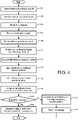
- FIGURE 4there is shown a flowchart describing one example implementation of a method for assessing fluid responsiveness in accordance with one embodiment, not being part of the invention.
- the methodologybegins at 400 , whereupon baseline physiological signals 48 are received from the various electrodes 14 , monitor 16 , plethysmograph 18 , and capnograph 20 by the capnography monitor 40 , ABP monitor 42 , ECG monitor 44 , and PPG monitor 46 via an I/O interface 38 .
- Baseline features and indices 52e.g., SVV, SPV, PPV, RRV, PVI, volumetric capnography, end-tidal CO2 derived from capnography, cardiac output derived from ABP, are then calculated at 402 via the processor 32 or other suitable component associated with the computer system 28 .
- a fluid challengeis initiated on the patient 10 via the infusion of fluid 26 by the infusion pump 24 in accordance with a preset amount, speed, and duration of administration of the fluid 26 .
- an example fluid challengeis a "mini-fluid challenge" corresponding to an infusion of 100 ml of colloid over 1 min.
- Other mini-challenges or fluid challengesmay be utilized in accordance with the systems and methods set forth herein depending upon the type of fluid being used, the apparent condition of the patient 10 , the experience of the doctor, or other factors.
- An example of a regular fluid challengemay administer 500mL of a fluid over 10-30 minutes.
- physiological signals 50 of the patient 10 during the fluid challengeare received from the above-noted input devices 14 , 16 , 18 , 20 by the monitors 40 , 42 , 44 , and 46 .
- a timing signal 54is received from the infusion pump 24 during the fluid challenge at 408 .
- the fluid challenge physiological signals 50are synchronized with the infusion pump timing signal 54 via the synchronization unit 56 or other suitable component of the computer system 28 .
- Fluid challenge features and indices 52are then calculated at 412 via the processor 32 or other suitable component associated with the computer system 28 .
- the various dynamic indices and/or features 52 and 58may be calculated during the expiration phase or portion 80 of the respiratory cycle of the patient.
- the expiration portion 80 of the respiratory cycleprovides greater variations for analysis by the ABP monitor 42 , ECG monitor 44 , PPG monitor 46 , as well as the calculations described above, as illustrated in FIGURES 2-3 .
- the classification algorithm 62is then utilized by the classification unit 60 or other suitable component associated with the computer system 28 with the baseline features and/or dynamic indices 52 and the fluid challenge features and/or dynamic indices 58 as inputs at 414 .
- the classification algorithm 62may be a logical regression algorithm that utilizes various features and/or dynamic indices 52 , 58 of the patient 10 during the expiration 80 or inspiration 82 portions of the respiratory cycle.
- a fluid responsiveness probability value 64is then calculated at 416 representing a probability that the patient 10 is responsive or non-responsive to fluid resuscitation.
- the fluid responsiveness probability value 64is representative of a value between 0 and 1, where values closer to 0 indicate that the patient 10 is unlikely to respond or will negatively respond to fluid resuscitation, while values closer to 1 indicate the patient 10 is responding or will respond favorably to fluid resuscitation.
- the fluid responsiveness probability value 64 calculated for the patient 10 undergoing the fluid challengeis then compared to a predetermined threshold response value 68 at 418 .
- the threshold response value 68is selected between 0 and 1, wherein a fluid responsiveness probability value 64 greater than or equal to the threshold value 68 is indicative of a patient 10 that will respond favorably to fluid resuscitation and a probability value 64 less than the threshold value 68 is indicative of a patient 10 that will respond negatively or have no response to fluid resuscitation.
- the threshold value 68may be selected in accordance with the fluid 26 being administered, the apparent type of injury or patient condition, the amount of time allotted for the challenge, the discretion of the attending physician, or myriad other medical considerations for IV support of a patient 10 .
- operationsproceed to 426 , whereupon a visual alert 76 is generated via the display device 34 or other suitable alerting mechanism as to the likelihood of a favorable response to fluid resuscitation by the patient 10 .
- operationsproceed to 422 .
- an alarme.g., audio alarm signal 70 , visual alarm signal 72 , is generated alerting attending personnel that the patient 10 is likely not responsive to fluid resuscitation or is negatively reacting to the fluid challenge.
- the fluid challengeif still being administered, is then terminated at 424 via the control signal 74 communicated to the infusion pump 24 .
- the attending physician or other caregivermay adjust the infusion rate of the infusion pump 24 responsive to the alarm 70 , 72 as an alternative to terminating the fluid challenge.
- a memoryincludes one or more of a non-transient computer readable medium; a magnetic disk or other magnetic storage medium; an optical disk or other optical storage medium; a random access memory (RAM), read-only memory (ROM), or other electronic memory device or chip or set of operatively interconnected chips; an Internet/Intranet server from which the stored instructions may be retrieved via the Internet/Intranet or a local area network; or so forth.
- a non-transient computer readable mediumincludes one or more of a non-transient computer readable medium; a magnetic disk or other magnetic storage medium; an optical disk or other optical storage medium; a random access memory (RAM), read-only memory (ROM), or other electronic memory device or chip or set of operatively interconnected chips; an Internet/Intranet server from which the stored instructions may be retrieved via the Internet/Intranet or a local area network; or so forth.
- a processorincludes one or more of a microprocessor, a microcontroller, a graphic processing unit (GPU), an application-specific integrated circuit (ASIC), an FPGA, and the like;
- a controllerincludes: (1) a processor and a memory, the processor executing computer executable instructions on the memory embodying the functionality of the controller; or (2) analog and/or digital hardware;
- a user input deviceincludes one or more of a mouse, a keyboard, a touch screen display, one or more buttons, one or more switches, one or more toggles, voice recognition engines, and the like;
- a databaseincludes one or more memories; and
- a display deviceincludes one or more of a LCD display, an LED display, a plasma display, a projection display, a touch screen display, and the like.
Landscapes
- Health & Medical Sciences (AREA)
- Life Sciences & Earth Sciences (AREA)
- Engineering & Computer Science (AREA)
- Biomedical Technology (AREA)
- Public Health (AREA)
- General Health & Medical Sciences (AREA)
- Medical Informatics (AREA)
- Animal Behavior & Ethology (AREA)
- Veterinary Medicine (AREA)
- Heart & Thoracic Surgery (AREA)
- Physics & Mathematics (AREA)
- Cardiology (AREA)
- Surgery (AREA)
- Molecular Biology (AREA)
- Pathology (AREA)
- Biophysics (AREA)
- Physiology (AREA)
- Artificial Intelligence (AREA)
- Signal Processing (AREA)
- Psychiatry (AREA)
- Computer Vision & Pattern Recognition (AREA)
- Pulmonology (AREA)
- Chemical & Material Sciences (AREA)
- Medicinal Chemistry (AREA)
- Bioinformatics & Cheminformatics (AREA)
- Vascular Medicine (AREA)
- Hematology (AREA)
- Primary Health Care (AREA)
- Epidemiology (AREA)
- Anesthesiology (AREA)
- Diabetes (AREA)
- Pharmacology & Pharmacy (AREA)
- Mathematical Physics (AREA)
- Fuzzy Systems (AREA)
- Obesity (AREA)
- Emergency Medicine (AREA)
- Evolutionary Computation (AREA)
- Microelectronics & Electronic Packaging (AREA)
- Business, Economics & Management (AREA)
- General Business, Economics & Management (AREA)
Description
- The present application relates generally to the medical arts. It finds a particular application in conjunction with medical monitoring, patient treatment, and the like, for use in hospitals, urgent care centers, emergency and/or trauma treatment, fluid resuscitation, and the like. However, it is to be understood that it also finds application in other usage scenarios and is not necessarily limited to the aforementioned applications.
- Fluid resuscitation is the first step in treating critically-ill patients who have been recognized as hemodynamically unstable. Unfortunately, only 50% of critically-ill patients in the operating room (OR), intensive care unit (ICU), or emergency department (ED) respond favorably to fluid resuscitation. Furthermore, those patients who do not respond favorably may be harmed by the treatment itself and consequently develop other clinical problems such as pulmonary or tissue edema. A predictive procedure for ascertaining whether a patient will be responsive to fluid resuscitation is by measuring changes in cardiac output before and after a fluid or mini-fluid challenge. Such a fluid challenge is a technique that consists of giving a small amount of intravenous fluids in a short period of time (also known as fluid bolus). By doing so, the clinician can assess whether the patient has a preload reserve that can be used to increase the stroke volume with further fluids.
- In normal individuals who are spontaneously breathing, the arterial blood pressure (ABP), R peak of electrocardiography (ECG), or amplitude in plethysmography (PPG) decreases during inspiration and increases during expiration. The normal fall in systolic blood pressure is less than 10 mmHg. When the fall in pressure during inspiration is more than 10 mmHg, this phenomenon is called pulsus paradoxus. A reverse of this phenomenon, i.e., systolic blood pressure, R peak, or PPG amplitude increases during inspiration and decreases during expiration, has been reported during positive pressure breathing (e.g., in patients who are mechanically ventilated).
- Dynamic indices derived from variations in ABP, ECG, or PPG with the respiratory cycle, i.e., pulse pressure variability (PPV), stroke volume variability (SVV), systolic pressure variability (SPV), RR variability (RRV), and pleth variability (PVI) (http://www.masimo.com/pvi/), have been shown to be very good predictors of fluid responsiveness (i.e., predicting an increased in stroke volume by 10-15% after fluid administration) in mechanically ventilated patients. Unfortunately, these dynamic indices are not accurate in predicting fluid responsiveness in spontaneously breathing patients, mainly because the variations of ABP, ECG, or PPG with the respiratory cycles are not very prominent (i.e., very low signal to noise ratio). It is worthy to mention that to assess fluid responsiveness in mechanically ventilated patients using these dynamic indices, patients do not need to undergo a fluid challenge. Patent application publications
US 2014/073890 A1 ,US 5 860 917 A andUS 2006/289020 A1 disclose systems for assessing fluid responsiveness based on analysis of physiological parameters measured during the administration of a fluid challenge. - The present application provides new and improved methods and systems which overcome the above-referenced challenges.
- In accordance with one aspect, a system for assessing fluid responsiveness is disclosed, comprising: at least one processor and an infusion pump in communication with the at least one processor, and a plurality of physiological monitors operable to receive physiological signals from an associated patient. The at least one processor is programmed to receive, from the infusion pump administering a fluid challenge to the associated patient, a timing signal corresponding to an infusion of fluids by the infusion pump during administration of the fluid challenge to the associated patient; synchronize physiological signals acquired from the associated patient during the fluid challenge with the timing signal of the infusion pump so as to indicate the amount of fluid provided to the associated patient in correlation with the corresponding physiological signal at a given time; calculate one or more dynamic indices and/or features from the synchronized physiological signals and calculate one or more dynamic indices and/or features from baseline physiological signals acquired from the patient prior to administration of the fluid challenge ; and determine a fluid responsiveness probability value of the patient using the one or more dynamic indices and/or features calculated from the synchronized physiological signals and using the one or more dynamic indices and/or features calculated from the baseline physiological signals.
- In accordance with another aspect, not being part of the invention, a fluid responsiveness assessing method is disclosed, comprising: receiving a plurality of physiological signals from a plurality of physiological monitors of an associated patient; receiving an infusion pump timing signal corresponding to an infusion of fluids by an associated infusion pump during administration of a fluid-challenge administered to the associated patient; synchronizing the timing signal with the received physiological signals so as to generate a synched physiological signal and to indicate the amount of fluid provided to the associated patient in correlation with the corresponding physiological signal at a given time; calculating at least one of a plurality of dynamic indices and/or features from synched fluid-challenge physiological signals; and calculating a fluid responsiveness probability value indicative of a responsiveness of the associated patient to fluid resuscitation.
- In an embodiment the method further comprises terminating the fluid challenge in response to the fluid responsiveness probability value indicative of the associated patient being non-responsive to fluid resuscitation. Moreover, the method may include receiving baseline physiological signals from the plurality of physiological monitors of the associated patient prior to initiation of the fluid challenge; and calculating at least one of a plurality of dynamic indices and/or features from the baseline physiological signals, wherein calculating the fluid responsiveness probability value is in accordance with the baseline dynamic indices and/or features and the fluid challenge dynamic indices and/or features, wherein calculating the fluid responsiveness probability value may further comprise applying the one or more dynamic indices and/or features from the synchronized physiological signals and the one or more dynamic indices and/or features from the baseline physiological signals into a classification algorithm.
- In an embodiment the method may further comprise generating an alarm responsive to the fluid responsiveness probability value indicative of the associated patient being non-responsive to fluid resuscitation. Moreover, the method may comprise generating a display of a likelihood of responding to fluid resuscitation of the associated patient responsive to the calculated fluid responsiveness probability value.
- The physiological signals preferentially correspond to an expiration portion of a respiratory cycle of the associated patient. The dynamic indices and/or features preferentially comprise at least one of pulse pressure variability, stroke volume variability, systolic pressure variability, RR variability, and pleth variability index, wherein the dynamic indices and/or features may comprise at least one of volumetric capnography, end-tidal CO2 derived from capnography, and cardiac output derived from ABP. The fluid challenge can be a mini-fluid challenge.
- In accordance with certain other disclosed aspects, a computer medium is disclosed storing instructions executable to control a computer and display to perform the method of the immediately preceding paragraph, and a system for assessing responsiveness of an associated patient to fluid resuscitation including a processor programmed to perform the method of the immediately preceding paragraph.
- One advantage resides in providing a systematic procedure to track stroke volume variations as a function of volume and rate of fluids administered to the patient.
- Another advantage resides in assessing fluid responsiveness in non-mechanically ventilated patients.
- Another advantage resides in minimizing fluid input for non-responsive patients.
- Still further advantages of the presently disclosed embodiments will be appreciated by those of ordinary skill in the art upon reading and understanding the following detailed description.
- The presently disclosed embodiments may take form in various components and arrangements of components, and in various steps and arrangements of steps. The drawings are only for purposes of illustrating the preferred embodiments and are not to be construed as limiting the presently disclosed embodiments.
FIGURE 1 diagrammatically illustrates a medical environment including a patient monitor including monitoring instruments configured to assess patient response to fluid resuscitation.FIGURE 2 illustrates baseline and fluid challenge physiological signals acquired from a patient for use in assessing fluid responsiveness.FIGURE 3 illustrates dynamic indices and/or features of fluid challenge physiological signals acquired from a patient for use in assessing fluid responsiveness.FIGURE 4 illustrates a method for assessing fluid responsiveness.- With reference to
FIGURE 1 , a fluidresponse assessment system 100 is depicted illustrating apatient 10 shown lying in abed 12 such as is a typical situation in a hospital, emergency room, intensive care unit (ICU), cardiac care unit (CCU), or so forth. Depending upon the patient's condition, it is also contemplated that thepatient 10 may be ambulatory, residing in a wheel chair, seated in a chair, or so forth. The patient is monitored by various medical monitoring devices, including in the illustrated embodiment an electrocardiographic (ECG) instrument withECG electrodes 14, ablood pressure monitor 16, which may for example be a wholly non-invasive sphygmometer or a minimally invasive arterial line, a plethysmograph (PPG)18, and acapnograph 20. The illustratedblood pressure monitor 16 is wrist-based; however, a blood pressure monitor located on the upper arm or elsewhere on thepatient 10 is also contemplated. If an arterial line is used to measure blood pressure, it may optionally be incorporated into an intravenous fluid delivery line or the like. TheECG 14, arterial blood pressure (ABP) monitor16,PPG 18, andcapnograph 20 further include associated electronics for generating and optionally performing signal processing on ECG, blood pressure signals, changes in volume within an organ or body (blood or air), and CO2 pressure in respiratory gases. - The fluid
response assessment system 100, as depicted inFIGURE 1 , includes an intravenous (IV) component comprising afluid 26,infusion pump 24, andline 22 for transferring thefluid 26 into thepatient 10. Theinfusion pump 24 may be implemented as a rapid infusion pump that is programmable via thecomputer system 28, remotely programmable, programmable via a user input component25 (touch screen/keypad/touchpad, etc.), or the like. In some embodiments, theinfusion pump 24 is programmed to administer a selected quantity offluid 26 to thepatient 10 during a predetermined time interval, e.g., a fluid challenge, also referenced as a mini-fluid challenge. The fluid challenge, as used in such settings, allows for an assessment of whether or not apatient 10 will respond to fluid resuscitation. The fluid challenge referenced herein corresponds to a limited amount offluid 26 infused into thepatient 10 during a discrete time interval, as opposed to the general provisioning of fluids. Thesystem 100 further includes acomputer system 28 in communication with theinfusion pump 24, thevarious electrodes 14,monitor 16, plethysmograph18, andcapnograph 20 via an I/O interface 38. According to one embodiment, the I/O interface 38 may communicate, via suitable communications links, with one or more of the variouspatient monitoring components system 100 may further include additional physiological monitoring devices, e.g., pulse oximeter, thermometer, glucose monitor, and the like. - The
computer system 28 coordinates the operations of thesystem 100, and may be remotely positioned therefrom. Thecomputer system 28 includes at least oneprocessor 32 and at least oneprogram memory 30. Theprogram memory 30 includes processor executable instructions that, when executed by theprocessor 32, coordinate the operation of thecomputer system 28, including physiological signal analysis and processing, classification of fluid response, alarm generation, and the like. Theprocessor 32 executes the processor executable instructions stored in theprogram memory 30. - The
computer system 28 further comprises electronics providing forcapnography monitoring 40,ABP monitoring 42,ECG monitoring 44, andPPG monitoring 46. Although not depicted inFIGURE 1 , thecomputer system 28 may optionally provide electronics for monitoring selected other physiological parameters such as respiration rate based on suitable physiological input signals. Thecomputer system 28 includes aprocessor 32 operable to control operations of thecomputer system 28, facilitate processing of physiological signals, execute instructions, perform calculations, facilitate comparisons and storage of various inputs and the like. - The
computer system 28 further includes adisplay device 34 in communication with theprocessor 32 and configured to display one or more displaying information such as physiological signals, test results, patient information, vitals, graphical user interface, alerts, and the like, and auser input device 36, such as a keyboard or touch or writable screen, for inputting text, and/or a cursor control device, such as a mouse, trackball, or the like, for communicating user input information and command selections to theprocessor 32. In one embodiment, thedisplay device 34 may be implemented as an integrated multi-functional patient monitor these electronics may be embodied within a unitary multi-functional patient monitor (not shown) that an integrated display of the resulting processed ECG, ABP, PPG, and/or capnography signals. Thedisplay device 34 may display measured physiological parameters such as the ECG trace, blood pressure (BP) data, respiratory data, or so forth. The display can display these parameters in various ways, such as by current numerical value, by a trace showing parameter value as a function of time, or so forth. - A
baseline signal module 48 of the processor executable instructions stored inmemory 30 controls receipt of physiological signals from themonitors patient 10 prior to administration of thefluid 26 during a fluid challenge. As discussed in greater detail below,FIGURE 2 provides an illustration of baselinephysiological signals monitors baseline feature calculator 52 of the processor executable instructions facilitates the derivation from the baselinephysiological signals 48, i.e., calculation, of dynamic indices and/or features from variations in ABP, ECG, or PPG with the respiratory cycle, i.e., pulse pressure variability (PPV), stroke volume variability (SVV), and systolic pressure variability (SPV). According to one embodiment, the dynamic indices may be calculated as follows:


- Additional dynamic indices and/or features may include RR variability (RRV), and pleth variability index (PVI). RRV may correspond to the variation in the time interval between heartbeats, i.e., measured by the variation in the beat-to-beat interval. The R-R variability (RRV) utilizes the interval between successive R's, where R is a peak of a QRS complex and RRV corresponds to the peak to peak of successive QRS complexes of the ECG wave. The pleth variability index (PVI) is a measurement associated with respiratory variations in pulse oximetry plethysmographic waveform amplitude for prediction of fluid responsiveness.
- The
baseline feature calculator 52 may further calculate various features, e.g., volumetric capnography, end-tidal CO2 derived from capnography, cardiac output derived from ABP, or the like, from the baseline physiological signals48. Physiological signals vary during the respiratory cycle, inhalation (inspiration)82 and exhalation (expiration)80. For example, in spontaneously breathing patients, during exhalation (expiration)80 of the respiratory cycle, blood pressure increases while during the inhalation (inspiration)82 of the respiratory cycle, blood pressure decreases. Accordingly, thebaseline feature calculator 52 is suitably configured to calculate the dynamic indices and/or features during theinspiration portion 82 of the respiratory cycle and during theexpiration portion 80 of the respiratory cycle. In one embodiment, the dynamic indices and/or features utilized pertain to only theinspiration portion 82 of the cycle or theexpiration portion 80 of the respiratory cycle. - A fluid challenge
physiological signal module 50 of the processor executable instructions stored inmemory 30 controls receipt of physiological signals frommonitors patient 10 is responsive to fluid resuscitation. An infusion pumptiming signal module 54 of the processor executable instructions receives an output from theinfusion pump 24 during the fluid challenge corresponding to the automated fluid administration to thepatient 10 by thepump 24. Asynchronization unit 56 of the processor executable instructions synchronizes thetiming signal 54 of theinfusion pump 24 with the fluid challengephysiological signals 50 so as to indicate the amount offluid 26 provided to the patient10 in correlation with the corresponding physiological signal at a given time. - A fluid
challenge feature calculator 58 of the processor executable instructions facilitates the derivation from the synchronized fluid challengephysiological signals 50, i.e., calculation, of dynamic indices and/or features from variations in ABP, ECG, or PPG with the respiratory cycle, e.g., PPV, SVV, SPV, RRV, and PVI. The fluidchallenge feature calculator 58 may further calculate various features, e.g., volumetric capnography, end-tidal CO2 derived from capnography, cardiac output derived from ABP, or the like, from the synchronizedphysiological signals 50 output via thesynchronization unit 56. The fluidchallenge feature calculator 58 is suitably configured to calculate the dynamic indices and/or features during theinspiration portion 82 of the respiratory cycle and during theexpiration portion 80 of the respiratory cycle occurring during administration of the fluid challenge. In one embodiment, the dynamic indices and/or features utilized pertain to only theinspiration portion 82 of the cycle or theexpiration portion 80 of the respiratory cycle during the administration of the fluid challenge. That is, the dynamic indices and/or features52 and58 are calculated using respectivephysiological signals inspiration portion 82 of the respiratory cycle of the associatedpatient 10. The respiratory cycle of the patient10 may be determined in accordance with the operations of thecapnography monitor 40. - A
classification unit 60 of the processor executable instructions employs aclassification algorithm 64 e.g., a probabilistic classification model, to which the fluid challenge features and/orindices 58 and baseline features and/orindices 52 are input to generate a fluidresponsiveness probability value 66. In accordance with one embodiment, the application of theclassification algorithm 64 corresponds to the use of the features and/or indices from thebaseline 52 and thefluid challenge 58 as inputs to a logistic regression algorithm. Theclassification algorithm 64 may be developed or trained during previous fluid challenges or preselected medical inputs based upon the age, weight, height, gender, race, or other medically relevant data. As discussed above, the features may include dynamic indices (SVV, SPV, PPV, RRV, PVI), volumetric capnography, end-tidal CO2, cardiac output, or the like. As previously addressed, the dynamic indices and/or other features may correspond to physiological signals collected during only the inspiration or expiration portion of the respiratory cycle of the patient10 to whom the fluid challenge is being administered. The fluidresponsiveness probability value 64 represents a score indicating the likelihood of the patient10 responding favorably to fluid resuscitation. In accordance with one embodiment, theprobability value 64 varies from 0 (i.e., thepatient 10 is not responsive) to 1 (i.e., thepatient 10 is responsive to fluids). - A
comparison unit 66 of the processor executable instructions facilitates comparison of the fluidresponsiveness probability value 64 to athreshold response value 68. Thethreshold response value 68 corresponds to a threshold at or above which thepatient 10 is responsive to fluid resuscitation and below which thepatient 10 is not responsive to fluid resuscitation. The fluidresuscitation assessment system 100 ofFIGURE 1 provides several exemplary outputs with respect to the result of thecomparison unit 66. As depicted therein, upon a determination that the fluidresponsiveness probability value 64 falls below thepredetermined threshold 68, the processor executable instructions include anaudio alarm signal 70, avisual alarm signal 72, acontrol signal 74 to the infusion pump24 (stop fluid challenge), and the like. The alarm signals70 may utilize suitable auditory devices, e.g., speaker78, whereas thealarm signal 72 may utilize thedisplay device 34 to provide a visual depiction of the ineffectiveness or non-responsiveness of the patient10 to fluid resuscitation, e.g., flashing graphic, blinking light, or myriad other suitable visually descriptive devices or indicia. Thecontrol signal 74 output to theinfusion pump 24 may indicate to thepump 24 to immediately cease infusion offluid 26 to thepatient 10, as discussed above, such fluid infusion may be harmful to anon-responding patient 10. Alternatively,such signal 74 may be interpreted by thepump 24 to begin emitting suitable auditory and/or visual queues to physicians, nurses, or the like, of the non-responsiveness of thepatient 10. When the fluidresponsiveness probability value 64 of thepatient 10 meets or exceeds thethreshold 66, the processor executable instructions of thesystem 100 include avisual alert 76 of the responsiveness of the patient 10 to fluid resuscitation. As a non-limiting example, thedisplay device 34 may produce a graphic, or other indicia reflecting the patient's positive response to fluid resuscitation. - The
computer system 28 may include a computer server, workstation, personal computer, cellular telephone, tablet computer, pager, combination thereof, or other computing device capable of executing instructions for performing the exemplary method. - According to one example embodiment, the
computer system 28 includes hardware, software, and/or any suitable combination thereof, configured to interact with an associated user, a networked device, networked storage, remote devices, or the like. - The
memory 30 may represent any type of non-transitory computer readable medium such as random access memory (RAM), read only memory (ROM), magnetic disk or tape, optical disk, flash memory, or holographic memory. In one embodiment, thememory 30 comprises a combination of random access memory and read only memory. In some embodiments, theprocessor 32 and thememory 30 may be combined in a single chip. The I/O interface 38 may allow thecomputer system 28 to communicate with other devices via a computer network, and may comprise a modulator/demodulator (MODEM).Memory 30 may store data processed in the method as well as the instructions for performing the exemplary method. - The
processor 32 can be variously embodied, such as by a single core processor, a dual core processor (or more generally by a multiple core processor), a digital processor and cooperating math and/or graphics coprocessor, a digital controller, or the like. Theprocessor 32 in addition to controlling the operation of thecomputer system 28, executes instructions and units stored in thememory 30 for performing the method outlined inFIGURE 4 . - The term "software," as used herein, is intended to encompass any collection or set of instructions executable by a computer or other digital system so as to configure the computer or other digital system to perform the task that is the intent of the software. The term "software," as further used herein, is intended to also encompass such instructions stored in storage mediums, such as RAM, a hard disk, optical disk, or so forth, and is intended to encompass so-called "firmware" that is software stored on a ROM or so forth. Such software may be organized in various ways, and may include software components organized as libraries, Internet-based programs stored on a remote server or so forth, source code, interpretive code, object code, directly executable code, and so forth. It is contemplated that the software may invoke system-level code or calls to other software residing on a server or other location to perform certain functions.
- Turning now to
FIGURE 2 , there is shown an illustrative example200 of the functioning of thesystem 100 in accordance with one example embodiment. As shown inFIGURE 2 , baselinephysiological signals 50 are depicted to the left prior to commencement of a fluid challenge to thepatient 10. The baselinephysiological signals 48 used in the illustrative example200 include a capnography signal39 (via capnography monitor40), an ABP signal40 (via ABP monitor42), an ECG signal43 (via ECG monitor44), and a PPG signal45 (via PPG monitor46). Thesesignals 48 are stored inmemory 30 and used for generation of dynamic indices and/or features52 as discussed above. After theinfusion pump 24 begins the systematic administration of fluids, i.e., the fluid challenge,physiological signals 50 are collected for thepatient 10 and time synchronized with the operation of thepump 24. As shown, theexpiration phase 80 and the inspiration phase82 (as shaded) are distinguishable from each other and impact thesignals Expiration 80 andinspiration 82 phases of the respiratory cycle may be identified from thecapnography signal 37, or be estimated from theABP signal 39, theECG signal 41, or thePPG signal 43. FIGURE 3 illustrates the collected physiological signals (48,50) and the correspondingdynamic indices 302 derived therefrom. As shown, SVV, SPV, and PPV are derived from theABP signal 39. RRV is derived from the receivedECG signal 41 as discussed above. PVI is derived from thePPG signal 43 as discussed above. Thedynamic indices 302 take advantage of the respiratory variations in theABP signal 39, theECG signal 41, or thePPG signal 43 to assess fluid responsiveness. Thesedynamic indices 302, in addition to thefeatures classification unit 60 to calculate a fluidresponsiveness probability value 64.- Turning now to
FIGURE 4 , there is shown a flowchart describing one example implementation of a method for assessing fluid responsiveness in accordance with one embodiment, not being part of the invention. - The methodology begins at400, whereupon baseline
physiological signals 48 are received from thevarious electrodes 14, monitor16,plethysmograph 18, andcapnograph 20 by thecapnography monitor 40, ABP monitor42, ECG monitor44, and PPG monitor46 via an I/O interface 38. Baseline features andindices 52, e.g., SVV, SPV, PPV, RRV, PVI, volumetric capnography, end-tidal CO2 derived from capnography, cardiac output derived from ABP, are then calculated at402 via theprocessor 32 or other suitable component associated with thecomputer system 28. - At404, a fluid challenge is initiated on the
patient 10 via the infusion offluid 26 by theinfusion pump 24 in accordance with a preset amount, speed, and duration of administration of the fluid26. In accordance with one embodiment, an example fluid challenge is a "mini-fluid challenge" corresponding to an infusion of 100 ml of colloid over 1 min. Other mini-challenges or fluid challenges may be utilized in accordance with the systems and methods set forth herein depending upon the type of fluid being used, the apparent condition of thepatient 10, the experience of the doctor, or other factors. An example of a regular fluid challenge may administer 500mL of a fluid over 10-30 minutes. - At406,
physiological signals 50 of the patient10 during the fluid challenge are received from the above-notedinput devices monitors timing signal 54 is received from theinfusion pump 24 during the fluid challenge at408. At410, the fluid challengephysiological signals 50 are synchronized with the infusionpump timing signal 54 via thesynchronization unit 56 or other suitable component of thecomputer system 28. Fluid challenge features andindices 52, e.g., SVV, SPV, PPV, RRV, PVI, volumetric capnography, end-tidal CO2 derived from capnography, cardiac output derived from ABP, are then calculated at412 via theprocessor 32 or other suitable component associated with thecomputer system 28. According to one embodiment, the various dynamic indices and/or features52 and58 may be calculated during the expiration phase orportion 80 of the respiratory cycle of the patient. In such an embodiment, theexpiration portion 80 of the respiratory cycle provides greater variations for analysis by theABP monitor 42, ECG monitor44, PPG monitor46, as well as the calculations described above, as illustrated inFIGURES 2-3 . - The
classification algorithm 62 is then utilized by theclassification unit 60 or other suitable component associated with thecomputer system 28 with the baseline features and/ordynamic indices 52 and the fluid challenge features and/ordynamic indices 58 as inputs at414. As discussed above, theclassification algorithm 62 may be a logical regression algorithm that utilizes various features and/ordynamic indices expiration 80 orinspiration 82 portions of the respiratory cycle. A fluidresponsiveness probability value 64 is then calculated at416 representing a probability that thepatient 10 is responsive or non-responsive to fluid resuscitation. The fluidresponsiveness probability value 64 is representative of a value between 0 and 1, where values closer to 0 indicate that thepatient 10 is unlikely to respond or will negatively respond to fluid resuscitation, while values closer to 1 indicate thepatient 10 is responding or will respond favorably to fluid resuscitation. - The fluid
responsiveness probability value 64 calculated for the patient10 undergoing the fluid challenge is then compared to a predeterminedthreshold response value 68 at418. As discussed above, thethreshold response value 68 is selected between 0 and 1, wherein a fluidresponsiveness probability value 64 greater than or equal to thethreshold value 68 is indicative of a patient10 that will respond favorably to fluid resuscitation and aprobability value 64 less than thethreshold value 68 is indicative of a patient10 that will respond negatively or have no response to fluid resuscitation. Thethreshold value 68 may be selected in accordance with the fluid26 being administered, the apparent type of injury or patient condition, the amount of time allotted for the challenge, the discretion of the attending physician, or myriad other medical considerations for IV support of apatient 10. - Accordingly, at420, a determination is made whether the fluid
responsiveness probability value 64 is greater than or less than the preselectedthreshold value 68. Upon a positive determination at420, operations proceed to426, whereupon avisual alert 76 is generated via thedisplay device 34 or other suitable alerting mechanism as to the likelihood of a favorable response to fluid resuscitation by thepatient 10. Upon a determination at420 that the fluidresponsiveness probability value 64 is less than thethreshold value 68, operations proceed to422. At422, an alarm, e.g.,audio alarm signal 70,visual alarm signal 72, is generated alerting attending personnel that thepatient 10 is likely not responsive to fluid resuscitation or is negatively reacting to the fluid challenge. The fluid challenge, if still being administered, is then terminated at424 via thecontrol signal 74 communicated to theinfusion pump 24. In accordance with one embodiment, the attending physician or other caregiver may adjust the infusion rate of theinfusion pump 24 responsive to thealarm - As used herein, a memory includes one or more of a non-transient computer readable medium; a magnetic disk or other magnetic storage medium; an optical disk or other optical storage medium; a random access memory (RAM), read-only memory (ROM), or other electronic memory device or chip or set of operatively interconnected chips; an Internet/Intranet server from which the stored instructions may be retrieved via the Internet/Intranet or a local area network; or so forth. Further, as used herein, a processor includes one or more of a microprocessor, a microcontroller, a graphic processing unit (GPU), an application-specific integrated circuit (ASIC), an FPGA, and the like; a controller includes: (1) a processor and a memory, the processor executing computer executable instructions on the memory embodying the functionality of the controller; or (2) analog and/or digital hardware; a user input device includes one or more of a mouse, a keyboard, a touch screen display, one or more buttons, one or more switches, one or more toggles, voice recognition engines, and the like; a database includes one or more memories; and a display device includes one or more of a LCD display, an LED display, a plasma display, a projection display, a touch screen display, and the like.
- The invention has been described with reference to the preferred embodiments. Modifications and alterations may occur to others upon reading and understanding the preceding detailed description. It is intended that the invention be construed as including all such modifications and alterations insofar as they come within the scope of the appended claims.


Claims (11)
- A system (100) for assessing fluid responsiveness, the system comprising:at least one processor(32);an infusion pump(24) in communication with the at least one processor(32); anda plurality of physiological monitors(40, 42, 44, 46) operable to receive physiological signals(48,50) from an associated patient(10);wherein the at least one processor(32) is programmed to:receive, from the infusion pump(24) administering a fluid challenge to the associated patient(10), a timing signal(54) corresponding to an infusion of fluids(26) by the infusion pump(24) during administration of the fluid challenge to the associated patient(10);
synchronize physiological signals(50) acquired from the associated patient (10) during the fluid challenge with the timing signal (54) of the infusion pump (24) so as to indicate the amount of fluid (26) provided to the associated patient (10) in correlation with the corresponding physiological signal at a given time;calculate one or more dynamic indices and/or features (58) from the synchronized physiological signals (50) and calculate one or more dynamic indices and/ or features (52) from baseline physiological signals (48) acquired from the patient (10) prior to administration of the fluid challenge; anddetermine a fluid responsiveness probability value (64) of the patient (10) based on the one or more dynamic indices and/or features (58) calculated from the synchronized physiological signals (50) and based on the one or more dynamic indices and/or features (52) calculated from the baseline physiological signals (48). - The system (100) according to claim 1, wherein the at least one processor (32) is further programmed to terminate operations of the infusion pump (24) responsive to the fluid responsiveness probability value (64) indicative of the patient (10) being non-responsive to fluid resuscitation.
- The system (100) according to any of claims 1-2 , wherein determining the fluid responsiveness probability value (64) further comprises inputting the one or more dynamic indices and/or features (58) from the synchronized physiological signals (50) and the one or more dynamic indices and/or features (52) from the baseline physiological signals (48) into a classification algorithm (62).
- The system (100) according to any of claims 1-3 , wherein the fluid responsiveness probability value (64) is between 0 indicating non-responsiveness and 1 indicating responsive.
- The system (100) according to claim 4 , wherein the at least one processor (32) is further programmed to compare the determined fluid responsiveness probability value (64) to a preselected threshold value (68), wherein the associated patient (10) is responsive to fluid resuscitation when the probability value (64) is greater than or equal to the threshold value (68).
- The system (100) according to any of claims 1-5 , wherein the at least one processor (32) is programmed to calculate the one or more dynamic indices and/or features (58) from the synchronized physiological signals (50) and the one or more dynamic indices and/or features (52) from the baseline physiological signals (48) during an expiration portion (80) of a respiratory cycle of the associated patient.
- The system (100) according to any of claims 1-6, wherein the at least one processor (32) is programmed to generate an alarm (70,72) in response to the determined fluid responsiveness probability value (64) indicating the associated patient (10) is not responsive to fluid resuscitation.
- The system (100) according to any of claims 1-7 , wherein the infusion pump (24) is a rapid infusion pump that is synchronized with the physiological signals (50) and configured to infuse a fluid (26) during an expiration portion (80) of the respiratory cycle of the associated patient (10).
- The system (100) according to any of claims 1-8 , wherein the plurality of physiological monitors comprise one or more of a capnography monitor (40), an arterial blood pressure (ABP) monitor (42), an electrocardiographic (ECG) monitor (44), a plethysmograph (PPG) monitor (46).
- The system (100) according to any of claims1-9 , wherein the dynamic indices and/or features (52,58) comprise at least one of pulse pressure variability (PPV), stroke volume variability (SVV), systolic pressure variability (SPV), RR variability (RRV), and pleth variability index (PVI).
- The system (100) according to claim1 0 , wherein the dynamic indices and/or features (52,58) comprise at least one of volumetric capnography, end-tidal CO2 derived from capnography, and cardiac output derived from ABP.
Applications Claiming Priority (2)
| Application Number | Priority Date | Filing Date | Title |
|---|---|---|---|
| US201462092858P | 2014-12-17 | 2014-12-17 | |
| PCT/IB2015/059456WO2016097935A1 (en) | 2014-12-17 | 2015-12-09 | Method and system for assessing fluid responsiveness using multimodal data |
Publications (2)
| Publication Number | Publication Date |
|---|---|
| EP3232915A1 EP3232915A1 (en) | 2017-10-25 |
| EP3232915B1true EP3232915B1 (en) | 2022-06-15 |
Family
ID=55080137
Family Applications (1)
| Application Number | Title | Priority Date | Filing Date |
|---|---|---|---|
| EP15823020.1AActiveEP3232915B1 (en) | 2014-12-17 | 2015-12-09 | System for assessing fluid responsiveness using multimodal data |
Country Status (7)
| Country | Link |
|---|---|
| US (1) | US10869631B2 (en) |
| EP (1) | EP3232915B1 (en) |
| JP (1) | JP6789947B2 (en) |
| CN (1) | CN107205674B (en) |
| BR (1) | BR112017012726A2 (en) |
| RU (1) | RU2017125476A (en) |
| WO (1) | WO2016097935A1 (en) |
Families Citing this family (10)
| Publication number | Priority date | Publication date | Assignee | Title |
|---|---|---|---|---|
| CN108937881B (en)* | 2017-05-23 | 2021-08-10 | 深圳市理邦精密仪器股份有限公司 | Method and apparatus for determining object volume responsiveness |
| EP3461404A1 (en) | 2017-09-27 | 2019-04-03 | Koninklijke Philips N.V. | A sensor system and sensing method for use in assessment of circulatory volume |
| US11504015B2 (en) | 2019-02-14 | 2022-11-22 | Medical Informatics Corp. | Method of predicting fluid responsiveness in patients |
| EP3942567A1 (en)* | 2019-03-19 | 2022-01-26 | Koninklijke Philips N.V. | Population-level gaussian processes for clinical time series forecasting |
| WO2020199102A1 (en)* | 2019-04-01 | 2020-10-08 | 深圳迈瑞生物医疗电子股份有限公司 | Liquid reactivity detection device and method |
| EP3956903A4 (en) | 2019-04-17 | 2023-01-11 | ICU Medical, Inc. | System for onboard electronic encoding of the contents and administration parameters of iv containers and the secure use and disposal thereof |
| KR102304714B1 (en)* | 2019-08-22 | 2021-09-24 | 한양대학교 산학협력단 | Smart infusion pump |
| CN114469012A (en)* | 2020-10-28 | 2022-05-13 | 深圳迈瑞生物医疗电子股份有限公司 | Method and monitoring system for assessing fluid responsiveness |
| CN116829061A (en)* | 2020-12-25 | 2023-09-29 | 深圳迈瑞生物医疗电子股份有限公司 | Monitoring device and method for determining accuracy of pulse pressure variation degree |
| CN114617578A (en)* | 2022-02-24 | 2022-06-14 | 苏州圣泽医疗科技有限公司 | Volume responsiveness detection method, device and system |
Family Cites Families (18)
| Publication number | Priority date | Publication date | Assignee | Title |
|---|---|---|---|---|
| US5860917A (en) | 1997-01-15 | 1999-01-19 | Chiron Corporation | Method and apparatus for predicting therapeutic outcomes |
| WO2004091688A2 (en)* | 2003-04-08 | 2004-10-28 | Medrad, Inc. | Fluid delivery systems, devices and methods for delivery of hazardous fluids |
| WO2005056087A1 (en) | 2003-12-05 | 2005-06-23 | Cardinal Health 303, Inc. | Patient-controlled analgesia with patient monitoring system |
| EP1910958A2 (en)* | 2005-06-08 | 2008-04-16 | Mediqual | System and method for dynamic determination of disease prognosis |
| US20090124867A1 (en)* | 2007-11-13 | 2009-05-14 | Hirsh Robert A | Method and device to administer anesthetic and or vosactive agents according to non-invasively monitored cardiac and or neurological parameters |
| US8298151B2 (en) | 2008-02-01 | 2012-10-30 | Universidad De Valladolid | Method and apparatus for evaluation of fluid responsiveness |
| US8246546B2 (en)* | 2008-09-30 | 2012-08-21 | General Electric Company | Method, arrangement and apparatus for monitoring fluid balance status of a subject |
| US20110077474A1 (en) | 2009-09-29 | 2011-03-31 | General Electric Company | Method, arrangement and apparatus for assessing fluid balance status of a subject |
| US20110270097A1 (en)* | 2010-04-28 | 2011-11-03 | Pedro Mateo Riobo Aboy | Method and apparatus for assessment of fluid responsiveness |
| US8532754B2 (en) | 2010-04-28 | 2013-09-10 | Sironis, Inc. | Method and apparatus for assessment of fluid responsiveness |
| RU110950U1 (en) | 2010-04-30 | 2011-12-10 | Государственное образовательное учреждение высшего профессионального образования "Оренбургский государственный университет" | BIOTECHNICAL BLOOD COAGING REGULATION SYSTEM |
| US20120179136A1 (en) | 2011-01-12 | 2012-07-12 | Rinehart Joseph B | System and method for closed-loop patient-adaptive hemodynamic management |
| EP2502555A1 (en)* | 2011-03-22 | 2012-09-26 | Bmeye B.V. | Non-invasive oxygen delivery measurement system and method |
| US8880155B2 (en) | 2012-02-24 | 2014-11-04 | Covidien Lp | Hypovolemia diagnosis technique |
| US20140073889A1 (en)* | 2012-09-12 | 2014-03-13 | Nellcor Puritan Bennett Llc | Systems and methods for determining fluid responsiveness |
| US20140073890A1 (en)* | 2012-09-12 | 2014-03-13 | Nellcor Puritan Bennett Llc | Systems and methods for determining fluid responsiveness |
| WO2014152260A1 (en) | 2013-03-15 | 2014-09-25 | Nilus Medical, Llc | Hemodynamic monitoring device and methods of using same |
| US20140323876A1 (en) | 2013-04-25 | 2014-10-30 | Covidien Lp | Systems and methods for determining fluid responsiveness in the presence of gain changes and baseline changes |
- 2015
- 2015-12-09EPEP15823020.1Apatent/EP3232915B1/enactiveActive
- 2015-12-09BRBR112017012726Apatent/BR112017012726A2/ennot_activeApplication Discontinuation
- 2015-12-09JPJP2017532179Apatent/JP6789947B2/enactiveActive
- 2015-12-09CNCN201580073653.5Apatent/CN107205674B/enactiveActive
- 2015-12-09USUS15/536,163patent/US10869631B2/enactiveActive
- 2015-12-09WOPCT/IB2015/059456patent/WO2016097935A1/enactiveApplication Filing
- 2015-12-09RURU2017125476Apatent/RU2017125476A/ennot_activeApplication Discontinuation
Also Published As
| Publication number | Publication date |
|---|---|
| EP3232915A1 (en) | 2017-10-25 |
| BR112017012726A2 (en) | 2018-03-13 |
| CN107205674A (en) | 2017-09-26 |
| CN107205674B (en) | 2020-08-04 |
| WO2016097935A1 (en) | 2016-06-23 |
| RU2017125476A3 (en) | 2019-07-17 |
| JP2018504952A (en) | 2018-02-22 |
| US20170360366A1 (en) | 2017-12-21 |
| RU2017125476A (en) | 2019-01-18 |
| JP6789947B2 (en) | 2020-11-25 |
| US10869631B2 (en) | 2020-12-22 |
Similar Documents
| Publication | Publication Date | Title |
|---|---|---|
| EP3232915B1 (en) | System for assessing fluid responsiveness using multimodal data | |
| US11464457B2 (en) | Determining an early warning score based on wearable device measurements | |
| JP7171665B2 (en) | Apparatus and method for providing control signals for blood pressure measuring devices | |
| US8668649B2 (en) | System for cardiac status determination | |
| US11445975B2 (en) | Methods and systems for improved prediction of fluid responsiveness | |
| CN102551699B (en) | The system that non-invasive cardiac output is determined | |
| EP2542148B1 (en) | Active physical perturbations to enhance intelligent medical monitoring | |
| US20180064354A1 (en) | Analysis and Characterization of Patient Signals | |
| EP2849639A1 (en) | Monitoring of cardiac output | |
| WO2019130296A1 (en) | Determining an early warning score based on wearable device measurements | |
| WO2016034907A1 (en) | Method of monitoring heart rate variability and the use of that method in the prediction of falls and other applications | |
| US20200196878A1 (en) | System and method for blood pressure monitoring with subject awareness information | |
| US20140316287A1 (en) | System and method for displaying fluid responsivenss predictors | |
| US20140180037A1 (en) | Biological Tissue Function Analysis | |
| WO2015140777A1 (en) | Systems and methods for pain measurement | |
| Lazazzera et al. | MonEco: a novel health monitoring ecosystem to predict respiratory and cardiovascular disorders | |
| CN112218575A (en) | Device for determining stress and/or pain levels | |
| US8460200B2 (en) | Physiologic parameter monitoring apparatus | |
| JP7295962B2 (en) | Methods and systems for improved prediction of fluid responsiveness | |
| Selina et al. | Android Based Heart-rate Monitoring System using ECG Sensor | |
| EP4029437A1 (en) | Blood pressure estimation | |
| WO2015198302A1 (en) | Device and system for communicating with a subject |
Legal Events
| Date | Code | Title | Description |
|---|---|---|---|
| STAA | Information on the status of an ep patent application or granted ep patent | Free format text:STATUS: THE INTERNATIONAL PUBLICATION HAS BEEN MADE | |
| PUAI | Public reference made under article 153(3) epc to a published international application that has entered the european phase | Free format text:ORIGINAL CODE: 0009012 | |
| STAA | Information on the status of an ep patent application or granted ep patent | Free format text:STATUS: REQUEST FOR EXAMINATION WAS MADE | |
| 17P | Request for examination filed | Effective date:20170717 | |
| AK | Designated contracting states | Kind code of ref document:A1 Designated state(s):AL AT BE BG CH CY CZ DE DK EE ES FI FR GB GR HR HU IE IS IT LI LT LU LV MC MK MT NL NO PL PT RO RS SE SI SK SM TR | |
| AX | Request for extension of the european patent | Extension state:BA ME | |
| DAV | Request for validation of the european patent (deleted) | ||
| DAX | Request for extension of the european patent (deleted) | ||
| RAP1 | Party data changed (applicant data changed or rights of an application transferred) | Owner name:KONINKLIJKE PHILIPS N.V. | |
| RIC1 | Information provided on ipc code assigned before grant | Ipc:A61B 5/021 20060101ALI20211130BHEP Ipc:A61B 5/083 20060101ALI20211130BHEP Ipc:A61B 5/0245 20060101ALI20211130BHEP Ipc:A61B 5/024 20060101ALI20211130BHEP Ipc:A61B 5/0205 20060101ALI20211130BHEP Ipc:A61M 5/142 20060101ALI20211130BHEP Ipc:G16H 40/67 20180101ALI20211130BHEP Ipc:A61B 5/352 20210101ALI20211130BHEP Ipc:A61B 5/335 20210101ALI20211130BHEP Ipc:A61M 5/172 20060101ALI20211130BHEP Ipc:A61B 5/00 20060101AFI20211130BHEP | |
| GRAP | Despatch of communication of intention to grant a patent | Free format text:ORIGINAL CODE: EPIDOSNIGR1 | |
| STAA | Information on the status of an ep patent application or granted ep patent | Free format text:STATUS: GRANT OF PATENT IS INTENDED | |
| INTG | Intention to grant announced | Effective date:20220107 | |
| GRAS | Grant fee paid | Free format text:ORIGINAL CODE: EPIDOSNIGR3 | |
| GRAA | (expected) grant | Free format text:ORIGINAL CODE: 0009210 | |
| STAA | Information on the status of an ep patent application or granted ep patent | Free format text:STATUS: THE PATENT HAS BEEN GRANTED | |
| AK | Designated contracting states | Kind code of ref document:B1 Designated state(s):AL AT BE BG CH CY CZ DE DK EE ES FI FR GB GR HR HU IE IS IT LI LT LU LV MC MK MT NL NO PL PT RO RS SE SI SK SM TR | |
| REG | Reference to a national code | Ref country code:CH Ref legal event code:EP Ref country code:GB Ref legal event code:FG4D | |
| REG | Reference to a national code | Ref country code:IE Ref legal event code:FG4D | |
| REG | Reference to a national code | Ref country code:DE Ref legal event code:R096 Ref document number:602015079484 Country of ref document:DE | |
| REG | Reference to a national code | Ref country code:AT Ref legal event code:REF Ref document number:1497883 Country of ref document:AT Kind code of ref document:T Effective date:20220715 | |
| REG | Reference to a national code | Ref country code:LT Ref legal event code:MG9D | |
| REG | Reference to a national code | Ref country code:NL Ref legal event code:MP Effective date:20220615 | |
| PG25 | Lapsed in a contracting state [announced via postgrant information from national office to epo] | Ref country code:SE Free format text:LAPSE BECAUSE OF FAILURE TO SUBMIT A TRANSLATION OF THE DESCRIPTION OR TO PAY THE FEE WITHIN THE PRESCRIBED TIME-LIMIT Effective date:20220615 Ref country code:NO Free format text:LAPSE BECAUSE OF FAILURE TO SUBMIT A TRANSLATION OF THE DESCRIPTION OR TO PAY THE FEE WITHIN THE PRESCRIBED TIME-LIMIT Effective date:20220915 Ref country code:LT Free format text:LAPSE BECAUSE OF FAILURE TO SUBMIT A TRANSLATION OF THE DESCRIPTION OR TO PAY THE FEE WITHIN THE PRESCRIBED TIME-LIMIT Effective date:20220615 Ref country code:HR Free format text:LAPSE BECAUSE OF FAILURE TO SUBMIT A TRANSLATION OF THE DESCRIPTION OR TO PAY THE FEE WITHIN THE PRESCRIBED TIME-LIMIT Effective date:20220615 Ref country code:GR Free format text:LAPSE BECAUSE OF FAILURE TO SUBMIT A TRANSLATION OF THE DESCRIPTION OR TO PAY THE FEE WITHIN THE PRESCRIBED TIME-LIMIT Effective date:20220916 Ref country code:FI Free format text:LAPSE BECAUSE OF FAILURE TO SUBMIT A TRANSLATION OF THE DESCRIPTION OR TO PAY THE FEE WITHIN THE PRESCRIBED TIME-LIMIT Effective date:20220615 Ref country code:BG Free format text:LAPSE BECAUSE OF FAILURE TO SUBMIT A TRANSLATION OF THE DESCRIPTION OR TO PAY THE FEE WITHIN THE PRESCRIBED TIME-LIMIT Effective date:20220915 | |
| REG | Reference to a national code | Ref country code:AT Ref legal event code:MK05 Ref document number:1497883 Country of ref document:AT Kind code of ref document:T Effective date:20220615 | |
| PG25 | Lapsed in a contracting state [announced via postgrant information from national office to epo] | Ref country code:RS Free format text:LAPSE BECAUSE OF FAILURE TO SUBMIT A TRANSLATION OF THE DESCRIPTION OR TO PAY THE FEE WITHIN THE PRESCRIBED TIME-LIMIT Effective date:20220615 Ref country code:LV Free format text:LAPSE BECAUSE OF FAILURE TO SUBMIT A TRANSLATION OF THE DESCRIPTION OR TO PAY THE FEE WITHIN THE PRESCRIBED TIME-LIMIT Effective date:20220615 | |
| PG25 | Lapsed in a contracting state [announced via postgrant information from national office to epo] | Ref country code:NL Free format text:LAPSE BECAUSE OF FAILURE TO SUBMIT A TRANSLATION OF THE DESCRIPTION OR TO PAY THE FEE WITHIN THE PRESCRIBED TIME-LIMIT Effective date:20220615 | |
| PG25 | Lapsed in a contracting state [announced via postgrant information from national office to epo] | Ref country code:SM Free format text:LAPSE BECAUSE OF FAILURE TO SUBMIT A TRANSLATION OF THE DESCRIPTION OR TO PAY THE FEE WITHIN THE PRESCRIBED TIME-LIMIT Effective date:20220615 Ref country code:SK Free format text:LAPSE BECAUSE OF FAILURE TO SUBMIT A TRANSLATION OF THE DESCRIPTION OR TO PAY THE FEE WITHIN THE PRESCRIBED TIME-LIMIT Effective date:20220615 Ref country code:RO Free format text:LAPSE BECAUSE OF FAILURE TO SUBMIT A TRANSLATION OF THE DESCRIPTION OR TO PAY THE FEE WITHIN THE PRESCRIBED TIME-LIMIT Effective date:20220615 Ref country code:PT Free format text:LAPSE BECAUSE OF FAILURE TO SUBMIT A TRANSLATION OF THE DESCRIPTION OR TO PAY THE FEE WITHIN THE PRESCRIBED TIME-LIMIT Effective date:20221017 Ref country code:ES Free format text:LAPSE BECAUSE OF FAILURE TO SUBMIT A TRANSLATION OF THE DESCRIPTION OR TO PAY THE FEE WITHIN THE PRESCRIBED TIME-LIMIT Effective date:20220615 Ref country code:EE Free format text:LAPSE BECAUSE OF FAILURE TO SUBMIT A TRANSLATION OF THE DESCRIPTION OR TO PAY THE FEE WITHIN THE PRESCRIBED TIME-LIMIT Effective date:20220615 Ref country code:CZ Free format text:LAPSE BECAUSE OF FAILURE TO SUBMIT A TRANSLATION OF THE DESCRIPTION OR TO PAY THE FEE WITHIN THE PRESCRIBED TIME-LIMIT Effective date:20220615 Ref country code:AT Free format text:LAPSE BECAUSE OF FAILURE TO SUBMIT A TRANSLATION OF THE DESCRIPTION OR TO PAY THE FEE WITHIN THE PRESCRIBED TIME-LIMIT Effective date:20220615 | |
| PG25 | Lapsed in a contracting state [announced via postgrant information from national office to epo] | Ref country code:PL Free format text:LAPSE BECAUSE OF FAILURE TO SUBMIT A TRANSLATION OF THE DESCRIPTION OR TO PAY THE FEE WITHIN THE PRESCRIBED TIME-LIMIT Effective date:20220615 Ref country code:IS Free format text:LAPSE BECAUSE OF FAILURE TO SUBMIT A TRANSLATION OF THE DESCRIPTION OR TO PAY THE FEE WITHIN THE PRESCRIBED TIME-LIMIT Effective date:20221015 | |
| REG | Reference to a national code | Ref country code:DE Ref legal event code:R097 Ref document number:602015079484 Country of ref document:DE | |
| PG25 | Lapsed in a contracting state [announced via postgrant information from national office to epo] | Ref country code:AL Free format text:LAPSE BECAUSE OF FAILURE TO SUBMIT A TRANSLATION OF THE DESCRIPTION OR TO PAY THE FEE WITHIN THE PRESCRIBED TIME-LIMIT Effective date:20220615 | |
| PLBE | No opposition filed within time limit | Free format text:ORIGINAL CODE: 0009261 | |
| STAA | Information on the status of an ep patent application or granted ep patent | Free format text:STATUS: NO OPPOSITION FILED WITHIN TIME LIMIT | |
| PG25 | Lapsed in a contracting state [announced via postgrant information from national office to epo] | Ref country code:DK Free format text:LAPSE BECAUSE OF FAILURE TO SUBMIT A TRANSLATION OF THE DESCRIPTION OR TO PAY THE FEE WITHIN THE PRESCRIBED TIME-LIMIT Effective date:20220615 | |
| 26N | No opposition filed | Effective date:20230316 | |
| PG25 | Lapsed in a contracting state [announced via postgrant information from national office to epo] | Ref country code:SI Free format text:LAPSE BECAUSE OF FAILURE TO SUBMIT A TRANSLATION OF THE DESCRIPTION OR TO PAY THE FEE WITHIN THE PRESCRIBED TIME-LIMIT Effective date:20220615 | |
| REG | Reference to a national code | Ref country code:CH Ref legal event code:PL | |
| REG | Reference to a national code | Ref country code:BE Ref legal event code:MM Effective date:20221231 | |
| PG25 | Lapsed in a contracting state [announced via postgrant information from national office to epo] | Ref country code:LU Free format text:LAPSE BECAUSE OF NON-PAYMENT OF DUE FEES Effective date:20221209 | |
| PG25 | Lapsed in a contracting state [announced via postgrant information from national office to epo] | Ref country code:LI Free format text:LAPSE BECAUSE OF NON-PAYMENT OF DUE FEES Effective date:20221231 Ref country code:IE Free format text:LAPSE BECAUSE OF NON-PAYMENT OF DUE FEES Effective date:20221209 Ref country code:CH Free format text:LAPSE BECAUSE OF NON-PAYMENT OF DUE FEES Effective date:20221231 | |
| PG25 | Lapsed in a contracting state [announced via postgrant information from national office to epo] | Ref country code:FR Free format text:LAPSE BECAUSE OF NON-PAYMENT OF DUE FEES Effective date:20221231 Ref country code:BE Free format text:LAPSE BECAUSE OF NON-PAYMENT OF DUE FEES Effective date:20221231 | |
| PG25 | Lapsed in a contracting state [announced via postgrant information from national office to epo] | Ref country code:IT Free format text:LAPSE BECAUSE OF FAILURE TO SUBMIT A TRANSLATION OF THE DESCRIPTION OR TO PAY THE FEE WITHIN THE PRESCRIBED TIME-LIMIT Effective date:20220615 | |
| PG25 | Lapsed in a contracting state [announced via postgrant information from national office to epo] | Ref country code:HU Free format text:LAPSE BECAUSE OF FAILURE TO SUBMIT A TRANSLATION OF THE DESCRIPTION OR TO PAY THE FEE WITHIN THE PRESCRIBED TIME-LIMIT; INVALID AB INITIO Effective date:20151209 | |
| PG25 | Lapsed in a contracting state [announced via postgrant information from national office to epo] | Ref country code:CY Free format text:LAPSE BECAUSE OF FAILURE TO SUBMIT A TRANSLATION OF THE DESCRIPTION OR TO PAY THE FEE WITHIN THE PRESCRIBED TIME-LIMIT Effective date:20220615 | |
| PG25 | Lapsed in a contracting state [announced via postgrant information from national office to epo] | Ref country code:MK Free format text:LAPSE BECAUSE OF FAILURE TO SUBMIT A TRANSLATION OF THE DESCRIPTION OR TO PAY THE FEE WITHIN THE PRESCRIBED TIME-LIMIT Effective date:20220615 | |
| PG25 | Lapsed in a contracting state [announced via postgrant information from national office to epo] | Ref country code:MC Free format text:LAPSE BECAUSE OF FAILURE TO SUBMIT A TRANSLATION OF THE DESCRIPTION OR TO PAY THE FEE WITHIN THE PRESCRIBED TIME-LIMIT Effective date:20220615 | |
| PG25 | Lapsed in a contracting state [announced via postgrant information from national office to epo] | Ref country code:TR Free format text:LAPSE BECAUSE OF FAILURE TO SUBMIT A TRANSLATION OF THE DESCRIPTION OR TO PAY THE FEE WITHIN THE PRESCRIBED TIME-LIMIT Effective date:20220615 Ref country code:MC Free format text:LAPSE BECAUSE OF FAILURE TO SUBMIT A TRANSLATION OF THE DESCRIPTION OR TO PAY THE FEE WITHIN THE PRESCRIBED TIME-LIMIT Effective date:20220615 | |
| PG25 | Lapsed in a contracting state [announced via postgrant information from national office to epo] | Ref country code:MT Free format text:LAPSE BECAUSE OF FAILURE TO SUBMIT A TRANSLATION OF THE DESCRIPTION OR TO PAY THE FEE WITHIN THE PRESCRIBED TIME-LIMIT Effective date:20220615 | |
| PG25 | Lapsed in a contracting state [announced via postgrant information from national office to epo] | Ref country code:BG Free format text:LAPSE BECAUSE OF FAILURE TO SUBMIT A TRANSLATION OF THE DESCRIPTION OR TO PAY THE FEE WITHIN THE PRESCRIBED TIME-LIMIT Effective date:20220615 | |
| REG | Reference to a national code | Ref country code:DE Ref legal event code:R084 Ref document number:602015079484 Country of ref document:DE | |
| PG25 | Lapsed in a contracting state [announced via postgrant information from national office to epo] | Ref country code:BG Free format text:LAPSE BECAUSE OF FAILURE TO SUBMIT A TRANSLATION OF THE DESCRIPTION OR TO PAY THE FEE WITHIN THE PRESCRIBED TIME-LIMIT Effective date:20220615 | |
| REG | Reference to a national code | Ref country code:GB Ref legal event code:746 Effective date:20241217 | |
| PGFP | Annual fee paid to national office [announced via postgrant information from national office to epo] | Ref country code:GB Payment date:20241217 Year of fee payment:10 | |
| PGFP | Annual fee paid to national office [announced via postgrant information from national office to epo] | Ref country code:DE Payment date:20241227 Year of fee payment:10 |