EP3231689B1 - Device and method for charging an electrically driven vehicle - Google Patents
Device and method for charging an electrically driven vehicleDownload PDFInfo
- Publication number
- EP3231689B1 EP3231689B1EP17000599.5AEP17000599AEP3231689B1EP 3231689 B1EP3231689 B1EP 3231689B1EP 17000599 AEP17000599 AEP 17000599AEP 3231689 B1EP3231689 B1EP 3231689B1
- Authority
- EP
- European Patent Office
- Prior art keywords
- charging
- vehicle
- station
- bus
- area
- Prior art date
- Legal status (The legal status is an assumption and is not a legal conclusion. Google has not performed a legal analysis and makes no representation as to the accuracy of the status listed.)
- Active
Links
Images


Classifications
- B—PERFORMING OPERATIONS; TRANSPORTING
- B60—VEHICLES IN GENERAL
- B60L—PROPULSION OF ELECTRICALLY-PROPELLED VEHICLES; SUPPLYING ELECTRIC POWER FOR AUXILIARY EQUIPMENT OF ELECTRICALLY-PROPELLED VEHICLES; ELECTRODYNAMIC BRAKE SYSTEMS FOR VEHICLES IN GENERAL; MAGNETIC SUSPENSION OR LEVITATION FOR VEHICLES; MONITORING OPERATING VARIABLES OF ELECTRICALLY-PROPELLED VEHICLES; ELECTRIC SAFETY DEVICES FOR ELECTRICALLY-PROPELLED VEHICLES
- B60L5/00—Current collectors for power supply lines of electrically-propelled vehicles
- B60L5/42—Current collectors for power supply lines of electrically-propelled vehicles for collecting current from individual contact pieces connected to the power supply line
- B—PERFORMING OPERATIONS; TRANSPORTING
- B60—VEHICLES IN GENERAL
- B60L—PROPULSION OF ELECTRICALLY-PROPELLED VEHICLES; SUPPLYING ELECTRIC POWER FOR AUXILIARY EQUIPMENT OF ELECTRICALLY-PROPELLED VEHICLES; ELECTRODYNAMIC BRAKE SYSTEMS FOR VEHICLES IN GENERAL; MAGNETIC SUSPENSION OR LEVITATION FOR VEHICLES; MONITORING OPERATING VARIABLES OF ELECTRICALLY-PROPELLED VEHICLES; ELECTRIC SAFETY DEVICES FOR ELECTRICALLY-PROPELLED VEHICLES
- B60L5/00—Current collectors for power supply lines of electrically-propelled vehicles
- B60L5/36—Current collectors for power supply lines of electrically-propelled vehicles with means for collecting current simultaneously from more than one conductor, e.g. from more than one phase
- B—PERFORMING OPERATIONS; TRANSPORTING
- B60—VEHICLES IN GENERAL
- B60L—PROPULSION OF ELECTRICALLY-PROPELLED VEHICLES; SUPPLYING ELECTRIC POWER FOR AUXILIARY EQUIPMENT OF ELECTRICALLY-PROPELLED VEHICLES; ELECTRODYNAMIC BRAKE SYSTEMS FOR VEHICLES IN GENERAL; MAGNETIC SUSPENSION OR LEVITATION FOR VEHICLES; MONITORING OPERATING VARIABLES OF ELECTRICALLY-PROPELLED VEHICLES; ELECTRIC SAFETY DEVICES FOR ELECTRICALLY-PROPELLED VEHICLES
- B60L53/00—Methods of charging batteries, specially adapted for electric vehicles; Charging stations or on-board charging equipment therefor; Exchange of energy storage elements in electric vehicles
- B60L53/10—Methods of charging batteries, specially adapted for electric vehicles; Charging stations or on-board charging equipment therefor; Exchange of energy storage elements in electric vehicles characterised by the energy transfer between the charging station and the vehicle
- B60L53/12—Inductive energy transfer
- B60L53/126—Methods for pairing a vehicle and a charging station, e.g. establishing a one-to-one relation between a wireless power transmitter and a wireless power receiver
- B—PERFORMING OPERATIONS; TRANSPORTING
- B60—VEHICLES IN GENERAL
- B60L—PROPULSION OF ELECTRICALLY-PROPELLED VEHICLES; SUPPLYING ELECTRIC POWER FOR AUXILIARY EQUIPMENT OF ELECTRICALLY-PROPELLED VEHICLES; ELECTRODYNAMIC BRAKE SYSTEMS FOR VEHICLES IN GENERAL; MAGNETIC SUSPENSION OR LEVITATION FOR VEHICLES; MONITORING OPERATING VARIABLES OF ELECTRICALLY-PROPELLED VEHICLES; ELECTRIC SAFETY DEVICES FOR ELECTRICALLY-PROPELLED VEHICLES
- B60L53/00—Methods of charging batteries, specially adapted for electric vehicles; Charging stations or on-board charging equipment therefor; Exchange of energy storage elements in electric vehicles
- B60L53/10—Methods of charging batteries, specially adapted for electric vehicles; Charging stations or on-board charging equipment therefor; Exchange of energy storage elements in electric vehicles characterised by the energy transfer between the charging station and the vehicle
- B60L53/14—Conductive energy transfer
- B60L53/16—Connectors, e.g. plugs or sockets, specially adapted for charging electric vehicles
- B—PERFORMING OPERATIONS; TRANSPORTING
- B60—VEHICLES IN GENERAL
- B60L—PROPULSION OF ELECTRICALLY-PROPELLED VEHICLES; SUPPLYING ELECTRIC POWER FOR AUXILIARY EQUIPMENT OF ELECTRICALLY-PROPELLED VEHICLES; ELECTRODYNAMIC BRAKE SYSTEMS FOR VEHICLES IN GENERAL; MAGNETIC SUSPENSION OR LEVITATION FOR VEHICLES; MONITORING OPERATING VARIABLES OF ELECTRICALLY-PROPELLED VEHICLES; ELECTRIC SAFETY DEVICES FOR ELECTRICALLY-PROPELLED VEHICLES
- B60L53/00—Methods of charging batteries, specially adapted for electric vehicles; Charging stations or on-board charging equipment therefor; Exchange of energy storage elements in electric vehicles
- B60L53/30—Constructional details of charging stations
- B60L53/34—Plug-like or socket-like devices specially adapted for contactless inductive charging of electric vehicles
- B—PERFORMING OPERATIONS; TRANSPORTING
- B60—VEHICLES IN GENERAL
- B60L—PROPULSION OF ELECTRICALLY-PROPELLED VEHICLES; SUPPLYING ELECTRIC POWER FOR AUXILIARY EQUIPMENT OF ELECTRICALLY-PROPELLED VEHICLES; ELECTRODYNAMIC BRAKE SYSTEMS FOR VEHICLES IN GENERAL; MAGNETIC SUSPENSION OR LEVITATION FOR VEHICLES; MONITORING OPERATING VARIABLES OF ELECTRICALLY-PROPELLED VEHICLES; ELECTRIC SAFETY DEVICES FOR ELECTRICALLY-PROPELLED VEHICLES
- B60L53/00—Methods of charging batteries, specially adapted for electric vehicles; Charging stations or on-board charging equipment therefor; Exchange of energy storage elements in electric vehicles
- B60L53/30—Constructional details of charging stations
- B60L53/35—Means for automatic or assisted adjustment of the relative position of charging devices and vehicles
- B60L53/36—Means for automatic or assisted adjustment of the relative position of charging devices and vehicles by positioning the vehicle
- B—PERFORMING OPERATIONS; TRANSPORTING
- B60—VEHICLES IN GENERAL
- B60L—PROPULSION OF ELECTRICALLY-PROPELLED VEHICLES; SUPPLYING ELECTRIC POWER FOR AUXILIARY EQUIPMENT OF ELECTRICALLY-PROPELLED VEHICLES; ELECTRODYNAMIC BRAKE SYSTEMS FOR VEHICLES IN GENERAL; MAGNETIC SUSPENSION OR LEVITATION FOR VEHICLES; MONITORING OPERATING VARIABLES OF ELECTRICALLY-PROPELLED VEHICLES; ELECTRIC SAFETY DEVICES FOR ELECTRICALLY-PROPELLED VEHICLES
- B60L53/00—Methods of charging batteries, specially adapted for electric vehicles; Charging stations or on-board charging equipment therefor; Exchange of energy storage elements in electric vehicles
- B60L53/30—Constructional details of charging stations
- B60L53/35—Means for automatic or assisted adjustment of the relative position of charging devices and vehicles
- B60L53/37—Means for automatic or assisted adjustment of the relative position of charging devices and vehicles using optical position determination, e.g. using cameras
- B—PERFORMING OPERATIONS; TRANSPORTING
- B60—VEHICLES IN GENERAL
- B60L—PROPULSION OF ELECTRICALLY-PROPELLED VEHICLES; SUPPLYING ELECTRIC POWER FOR AUXILIARY EQUIPMENT OF ELECTRICALLY-PROPELLED VEHICLES; ELECTRODYNAMIC BRAKE SYSTEMS FOR VEHICLES IN GENERAL; MAGNETIC SUSPENSION OR LEVITATION FOR VEHICLES; MONITORING OPERATING VARIABLES OF ELECTRICALLY-PROPELLED VEHICLES; ELECTRIC SAFETY DEVICES FOR ELECTRICALLY-PROPELLED VEHICLES
- B60L53/00—Methods of charging batteries, specially adapted for electric vehicles; Charging stations or on-board charging equipment therefor; Exchange of energy storage elements in electric vehicles
- B60L53/30—Constructional details of charging stations
- B60L53/35—Means for automatic or assisted adjustment of the relative position of charging devices and vehicles
- B60L53/38—Means for automatic or assisted adjustment of the relative position of charging devices and vehicles specially adapted for charging by inductive energy transfer
- B—PERFORMING OPERATIONS; TRANSPORTING
- B60—VEHICLES IN GENERAL
- B60L—PROPULSION OF ELECTRICALLY-PROPELLED VEHICLES; SUPPLYING ELECTRIC POWER FOR AUXILIARY EQUIPMENT OF ELECTRICALLY-PROPELLED VEHICLES; ELECTRODYNAMIC BRAKE SYSTEMS FOR VEHICLES IN GENERAL; MAGNETIC SUSPENSION OR LEVITATION FOR VEHICLES; MONITORING OPERATING VARIABLES OF ELECTRICALLY-PROPELLED VEHICLES; ELECTRIC SAFETY DEVICES FOR ELECTRICALLY-PROPELLED VEHICLES
- B60L2200/00—Type of vehicles
- B60L2200/18—Buses
- B—PERFORMING OPERATIONS; TRANSPORTING
- B60—VEHICLES IN GENERAL
- B60L—PROPULSION OF ELECTRICALLY-PROPELLED VEHICLES; SUPPLYING ELECTRIC POWER FOR AUXILIARY EQUIPMENT OF ELECTRICALLY-PROPELLED VEHICLES; ELECTRODYNAMIC BRAKE SYSTEMS FOR VEHICLES IN GENERAL; MAGNETIC SUSPENSION OR LEVITATION FOR VEHICLES; MONITORING OPERATING VARIABLES OF ELECTRICALLY-PROPELLED VEHICLES; ELECTRIC SAFETY DEVICES FOR ELECTRICALLY-PROPELLED VEHICLES
- B60L2240/00—Control parameters of input or output; Target parameters
- B60L2240/60—Navigation input
- B60L2240/62—Vehicle position
- B—PERFORMING OPERATIONS; TRANSPORTING
- B60—VEHICLES IN GENERAL
- B60L—PROPULSION OF ELECTRICALLY-PROPELLED VEHICLES; SUPPLYING ELECTRIC POWER FOR AUXILIARY EQUIPMENT OF ELECTRICALLY-PROPELLED VEHICLES; ELECTRODYNAMIC BRAKE SYSTEMS FOR VEHICLES IN GENERAL; MAGNETIC SUSPENSION OR LEVITATION FOR VEHICLES; MONITORING OPERATING VARIABLES OF ELECTRICALLY-PROPELLED VEHICLES; ELECTRIC SAFETY DEVICES FOR ELECTRICALLY-PROPELLED VEHICLES
- B60L2250/00—Driver interactions
- B60L2250/16—Driver interactions by display
- Y—GENERAL TAGGING OF NEW TECHNOLOGICAL DEVELOPMENTS; GENERAL TAGGING OF CROSS-SECTIONAL TECHNOLOGIES SPANNING OVER SEVERAL SECTIONS OF THE IPC; TECHNICAL SUBJECTS COVERED BY FORMER USPC CROSS-REFERENCE ART COLLECTIONS [XRACs] AND DIGESTS
- Y02—TECHNOLOGIES OR APPLICATIONS FOR MITIGATION OR ADAPTATION AGAINST CLIMATE CHANGE
- Y02T—CLIMATE CHANGE MITIGATION TECHNOLOGIES RELATED TO TRANSPORTATION
- Y02T10/00—Road transport of goods or passengers
- Y02T10/60—Other road transportation technologies with climate change mitigation effect
- Y02T10/70—Energy storage systems for electromobility, e.g. batteries
- Y—GENERAL TAGGING OF NEW TECHNOLOGICAL DEVELOPMENTS; GENERAL TAGGING OF CROSS-SECTIONAL TECHNOLOGIES SPANNING OVER SEVERAL SECTIONS OF THE IPC; TECHNICAL SUBJECTS COVERED BY FORMER USPC CROSS-REFERENCE ART COLLECTIONS [XRACs] AND DIGESTS
- Y02—TECHNOLOGIES OR APPLICATIONS FOR MITIGATION OR ADAPTATION AGAINST CLIMATE CHANGE
- Y02T—CLIMATE CHANGE MITIGATION TECHNOLOGIES RELATED TO TRANSPORTATION
- Y02T10/00—Road transport of goods or passengers
- Y02T10/60—Other road transportation technologies with climate change mitigation effect
- Y02T10/7072—Electromobility specific charging systems or methods for batteries, ultracapacitors, supercapacitors or double-layer capacitors
- Y—GENERAL TAGGING OF NEW TECHNOLOGICAL DEVELOPMENTS; GENERAL TAGGING OF CROSS-SECTIONAL TECHNOLOGIES SPANNING OVER SEVERAL SECTIONS OF THE IPC; TECHNICAL SUBJECTS COVERED BY FORMER USPC CROSS-REFERENCE ART COLLECTIONS [XRACs] AND DIGESTS
- Y02—TECHNOLOGIES OR APPLICATIONS FOR MITIGATION OR ADAPTATION AGAINST CLIMATE CHANGE
- Y02T—CLIMATE CHANGE MITIGATION TECHNOLOGIES RELATED TO TRANSPORTATION
- Y02T10/00—Road transport of goods or passengers
- Y02T10/60—Other road transportation technologies with climate change mitigation effect
- Y02T10/72—Electric energy management in electromobility
- Y—GENERAL TAGGING OF NEW TECHNOLOGICAL DEVELOPMENTS; GENERAL TAGGING OF CROSS-SECTIONAL TECHNOLOGIES SPANNING OVER SEVERAL SECTIONS OF THE IPC; TECHNICAL SUBJECTS COVERED BY FORMER USPC CROSS-REFERENCE ART COLLECTIONS [XRACs] AND DIGESTS
- Y02—TECHNOLOGIES OR APPLICATIONS FOR MITIGATION OR ADAPTATION AGAINST CLIMATE CHANGE
- Y02T—CLIMATE CHANGE MITIGATION TECHNOLOGIES RELATED TO TRANSPORTATION
- Y02T90/00—Enabling technologies or technologies with a potential or indirect contribution to GHG emissions mitigation
- Y02T90/10—Technologies relating to charging of electric vehicles
- Y02T90/12—Electric charging stations
- Y—GENERAL TAGGING OF NEW TECHNOLOGICAL DEVELOPMENTS; GENERAL TAGGING OF CROSS-SECTIONAL TECHNOLOGIES SPANNING OVER SEVERAL SECTIONS OF THE IPC; TECHNICAL SUBJECTS COVERED BY FORMER USPC CROSS-REFERENCE ART COLLECTIONS [XRACs] AND DIGESTS
- Y02—TECHNOLOGIES OR APPLICATIONS FOR MITIGATION OR ADAPTATION AGAINST CLIMATE CHANGE
- Y02T—CLIMATE CHANGE MITIGATION TECHNOLOGIES RELATED TO TRANSPORTATION
- Y02T90/00—Enabling technologies or technologies with a potential or indirect contribution to GHG emissions mitigation
- Y02T90/10—Technologies relating to charging of electric vehicles
- Y02T90/14—Plug-in electric vehicles
- Y—GENERAL TAGGING OF NEW TECHNOLOGICAL DEVELOPMENTS; GENERAL TAGGING OF CROSS-SECTIONAL TECHNOLOGIES SPANNING OVER SEVERAL SECTIONS OF THE IPC; TECHNICAL SUBJECTS COVERED BY FORMER USPC CROSS-REFERENCE ART COLLECTIONS [XRACs] AND DIGESTS
- Y02—TECHNOLOGIES OR APPLICATIONS FOR MITIGATION OR ADAPTATION AGAINST CLIMATE CHANGE
- Y02T—CLIMATE CHANGE MITIGATION TECHNOLOGIES RELATED TO TRANSPORTATION
- Y02T90/00—Enabling technologies or technologies with a potential or indirect contribution to GHG emissions mitigation
- Y02T90/10—Technologies relating to charging of electric vehicles
- Y02T90/16—Information or communication technologies improving the operation of electric vehicles
Definitions
- the inventionrelates to a device for charging an electrically powered bus, a method for charging an electrically powered bus and an electrically powered bus.
- Such a busin particular a so-called battery bus, usually has an energy storage device, for example a traction battery, by means of which electrical energy for driving the bus can be stored.
- This energy storage devicecan be charged with electrical energy at stationary charging stations or charging columns that are specially provided for charging the bus.
- the charging stationsare designed in such a way that only buses with a defined charging device for charging the bus can be charged at them.
- a bus with a pantograph as a charging contact for charging the buscan only be charged at a charging station if the pantograph is arranged on the bus in such a way that it is in a fixed or predetermined stop position or charging position of the bus in contact with a corresponding one Charging station side charging contact can be brought.
- the predetermined stopping position for the buscan be displayed to a driver of the bus, for example by a sign or a lane marking.
- such a charging stationhas the disadvantage that only buses with a pantograph arranged in a defined manner can be charged at this station.
- the WO 2016/050410 A1shows a method for supporting the positioning of a bus with an energy storage device relative to a stationary charging station.
- markingsare provided on the roadway in the area of the charging station.
- a drivercan position the bus at a defined distance parallel to the charging station.
- a positioning system for a vehicle for inductive charging on a stationary charging stationis known.
- a camerais used to determine the position of a vehicle with respect to the stationary charging station by detecting distinctive points on the vehicle, such as headlights, exterior mirrors or the license plate, when determining the vehicle to the stationary charging station.
- the position of these points in the world coordinate systemis known, whereby the distance between the vehicle and the camera can be determined.
- these points obtained in the world coordinate systemare compared with reference world points, the reference world points being calculated in a one-time calibration process in which the vehicle was parked in the optimal position.
- the EP 2,981,432describes a device for charging an electrically powered bus.
- the busis charged without it having to be positioned exactly in a charging position with respect to the stationary charging station.
- the contact on the charging station sideis formed over a great length, so that charging is possible even if the bus is not precisely positioned in the area of the stationary charging station.
- a device for charging an electrically powered busis known, the bus being charged in a stationary charging station by means of a pantograph attached to the roof of the bus.
- a first antennais arranged on the charging station and a second antenna is arranged on the roof of the bus, a radio signal being exchanged between the antennas. If the signal strength of the radio signal exceeds a threshold value, the bus is positioned sufficiently close to the stationary charging station.
- the object of the inventionis to provide a device and a method for charging an electrically powered bus, by means of which the flexibility of the charging station is increased.
- a device for charging an electrically powered buswith a stationary charging station with a charging area that can be arranged for charging the bus in a defined vicinity in the area of a corresponding vehicle-side charging area.
- the charging stationhas a position determining device, by means of which the current position of the at least one charging area of the bus located in the vicinity of the charging station can be determined relative to the charging station, in particular relative to the corresponding charging station-side charging area.
- At least one output device connected to the position determination device for signaling purposesis provided, by means of which instructions and / or information for driving the bus into a loading position can be output to a driver depending on the determined position of the vehicle-side loading area a charging station-side charging area is or can be arranged in the defined near area in the area of the vehicle-side charging area.
- the flexibility of the charging stationis increased, since now the position of the at least one vehicle-side charging area relative to the charging station is first determined. Depending on this determined position, the charging position in which the vehicle can be charged is then determined and the driver or the vehicle is guided to this charging position.
- a vehiclecan thus be charged at a single charging station regardless of the positioning of the vehicle-side charging area on the vehicle and also regardless of the vehicle type.
- the possibilities for arranging the vehicle-side loading area on the vehicleare increased, so that the vehicle-side loading area can be arranged on the vehicle where it is particularly advantageous for the respective vehicle concept. Furthermore, it is also possible for an operating company to operate or charge a mixed fleet of vehicles at the same charging station.
- the position determination deviceis formed by an image acquisition device designed as a camera.
- the position of the at least one vehicle-side charging contactis preferably determined in a manner similar to that of a "birdview" system, as it is, for example, from FIG EP 2 902 261 A1 is known.
- the vehiclein particular the vehicle-side charging area, can also be assigned a transmission device by means of which a position signal is output to the charging station to determine the position of the vehicle-side charging area.
- is at least an output deviceis provided which is signal-connected to the position-determining device.
- the vehicle and the charging stationcan also be connected to one another in a data-transmitting and / or signal-transmitting manner in order to be able to guide the vehicle into the charging position.
- the vehicle and the charging stationpreferably coordinate with one another interactively.
- the at least one output deviceis assigned to the charging station in order to further increase the flexibility of the charging station.
- the instructions or the informationcan be output to the driver of the vehicle independently of the vehicle to be charged.
- the output device on the charging station sideis formed by a screen by means of which optical instructions and / or information can be displayed to the driver. Using the screen on the charging station side, a red signal to stop the vehicle, a yellow signal to stop the vehicle soon and a green signal to move the vehicle forward can be displayed, for example, similar to a traffic light or a light signal system.
- arrows with the meaning “Forward”, “Stop” and “Back” or terms such as “Next”, “Stop” or “Stop” and “Back”can be displayed by means of the screen.
- acoustic instructions and / or informationcan also be output by means of the output device on the charging station side.
- the screenis preferably arranged at the charging station in such a way that the driver recognizes or records the display of the screen when he is sitting in a driver's seat of the vehicle. As a result, the vehicle can be brought into the charging position and charged in a particularly convenient way.
- the at least one output devicecan also be assigned to the vehicle in order to make the charging station particularly simple and inexpensive. It is preferably provided that optical and / or acoustic instructions or information can be output to the driver by means of the at least one output device on the vehicle.
- the optical instructions and / or informationcan, for example, be designed similarly to the instructions of the output device on the charging station side, which have already been mentioned as an example.
- the acoustic instructions or informationcan be designed, for example, similar to a parking assistant for acoustic orientation, in particular with the instructions “drive further forward”, “stop” or “stop” and “back”.
- the output device on the vehicle sideis preferably formed by a screen by means of which optical instructions and / or information can be displayed to the driver.
- the output devicecan also be assigned to an additional, stationary output station specifically provided for outputting the instructions or information to the driver.
- an output stationis particularly advantageous, for example, when the vehicle-side loading area and the driver's seat or the driver's workplace of the vehicle are arranged far away from one another. It is preferably provided that the charging station and the output station are arranged at a distance from one another, in particular at a defined distance.
- the current position of the vehicle relative to the loading positionis preferably displayed to the driver as information by means of the optical output device, in particular in a view from above.
- the drivercan bring the vehicle into the loading position in a simple and effective manner.
- the vehicleis displayed in its current position and a loading position area that the vehicle occupies in the loading position by means of the optical output device in a view from above, in particular in a simplified representation. In this way, the driver can bring the vehicle into the loading position in a particularly convenient and reliable manner.
- the displayis preferably also similar to a "birdview" system.
- the charging area on the charging station sideis formed by at least one charging contact which, for charging the vehicle, can be brought into contact with at least one corresponding vehicle-side charging contact as the vehicle-side charging area.
- the at least one vehicle-side charging contactis formed by a pantograph in order to make the vehicle-side charging contact functionally reliable and flexible.
- the output deviceis preferably signal-connected to a vehicle information determination device, by means of which the width of the vehicle and / or the height of the vehicle and / or the length of the vehicle and / or the vehicle type and / or the position of the vehicle-side loading area on the vehicle are determined can.
- a vehicle information ascertainment deviceBy means of such a vehicle information ascertainment device, the loading position in which the vehicle can be charged, determined with high accuracy and corresponding instructions or information are output to the driver of the vehicle.
- a method for charging an electrically powered busis also claimed, with a stationary charging station with a charging area that is arranged for charging the bus in a defined vicinity in the area of a corresponding vehicle-side charging area.
- the charging stationhas a position determining device by means of which the current position of the charging area of the bus located in the vicinity of the charging station is determined relative to the charging station, in particular relative to the corresponding charging station-side charging area.
- At least one output deviceconnected to the position determination device for signaling purposes, by means of which instructions and / or information on driving the vehicle into a loading position are output to a driver of the vehicle depending on the determined position of the vehicle-side charging area, in which the charging station-side charging area is or can be arranged in the defined near area in the area of the vehicle-side loading area.
- a charging station for charging an electrically powered vehiclein particular an electrically powered bus
- a charging areathat can be arranged for charging the vehicle in a defined vicinity in the area of a corresponding vehicle-side charging contact.
- the charging stationhas a position determining device by means of which the current position of the charging area of the vehicle located in the vicinity of the charging station can be determined relative to the charging station, in particular relative to the corresponding charging station-side charging area.
- the position determination deviceis signal-connected to an output device, by means of which instructions and / or information on driving the vehicle are sent to a driver of the vehicle in the vicinity of the charging station as a function of the determined position of the vehicle-side charging area a charging position can be output in which the charging station-side charging area is or can be arranged in the defined close-up area in the area of the at least one vehicle-side charging contact.
- a device 1 according to the inventionis shown.
- the device 1has a stationary charging station or charging column 3 with in Fig. 1 electrical charging contacts 5 indicated by dashed lines.
- the charging station 3is embodied here, for example, essentially L-shaped.
- An L-leg 7 of the charging station 3is here essentially oriented vertically or in the vertical axis direction z and is fixed with a free end region 9 on the bottom side.
- An L-leg 11 of the charging station 3is aligned here essentially horizontally or in the direction of the transverse axis y and has the charging contacts 5 at a free end region 13.
- the charging station 3here also has an image acquisition device embodied as a camera 15, by means of which the surroundings of the charging station 3 are recorded in an image or film. From the recordings of the camera 15, a signal connected to the camera 15, in Fig. 1 Evaluation unit 17 of the charging station 3, indicated by dashed lines, as to whether a vehicle with a pantograph as the vehicle-side charging contact is in the vicinity of the charging station 3. If such a vehicle is in the vicinity of the charging station 3, the evaluation unit 17 is used to determine the current position of the pantograph relative to the charging station-side charging contacts 5. The camera 15 and the evaluation unit 17 thus form a position determination device 18 for determining the current position of a vehicle-side charging contact relative to the charging station-side charging contacts 5. In addition to the camera 15 shown here by way of example, further image acquisition devices can also be provided.
- the charging station 3here also has, for example, an output device designed as a screen 19 and connected to the evaluation unit 17 for signaling purposes.
- an output devicedesigned as a screen 19 and connected to the evaluation unit 17 for signaling purposes.
- the screen 19By means of the screen 19, instructions for driving the vehicle into a defined charging position are output to a driver of a vehicle located in the vicinity of the charging station 3 as a function of the determined position of the vehicle-mounted pantograph.
- the charging station-side charging contacts 5can be brought into contact with the vehicle-side charging contacts or with the vehicle-side pantograph and the vehicle can be charged.
- the width, the length and the position of the pantograph 23 on the vehicleare also determined here by means of the camera 15 and the evaluation unit 17.
- a vehicle designed as a bus 21 with a pantograph 23is shown here, which is already in the defined loading position. "Stop" is then displayed to the driver of the bus 21 by means of the screen 19, so that the driver knows that he has to stay with the bus 21 in the current position in order to charge the bus 21. If the bus 21, viewed in the longitudinal direction x, is still behind the defined loading position, the driver is shown an in Fig. 1 with dashed lines indicated arrow 25 to the front. If the bus 21 is in front of the defined loading position, an in Fig. 1 indicated by dashed lines arrow 27 to the rear.
- the screen 19is arranged here at the charging station 3 in such a way that the driver of the bus 21 recognizes the display of the screen 19 when he is sitting in a driver's seat of the bus 21, as shown in Fig. 1 is shown.
- the screen 19protrudes here in the longitudinal direction x to the front from the L-leg 7 of the charging station 3.
- the screen 19here, viewed in vertical direction z, is arranged essentially centrally on the L-leg 7 of the charging station 3.
- a display surface 29 of the screen 9runs here essentially in the vertical direction z and in the longitudinal direction x.
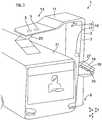
- a second embodiment of an output device for outputting instructions or information to the driver of the bus 21is shown.
- the output deviceis formed here by a vehicle-side screen 31, by means of which the driver of the bus 21 can be shown the current position of the bus 21 relative to the determined loading position as information.
- the screen 31is signal-connected to the evaluation unit 17 on the charging station side.
- the position and dimensions of an in Fig. 2 Charging position area 35 indicated by dashed linescan be determined.
- the bus 21must be parked on this charging position surface 35 in order to be able to charge it by means of the charging station 3.
- the screen 31the bus 21 in its current position and the charging position area 35 are then displayed in a view from above. By means of such a display, the driver can bring the bus 21 into the loading position in a simple and effective manner.
- a third embodiment of an output device for outputting instructions or information to the driver of the bus 21is shown.
- the screen 19is not assigned to the charging station 3, but rather to a separate output station or output column 37 that is provided in addition to the charging station 3.
- the charging station 3 and the output station 37are here arranged at a defined distance from one another in the longitudinal direction x.
- the output stationis arranged here in the longitudinal direction in front of the charging station 3. In this way, by means of the device 1, buses 21 can be charged, the pantograph of which is arranged on a rear area of the bus 21.
Landscapes
- Engineering & Computer Science (AREA)
- Power Engineering (AREA)
- Transportation (AREA)
- Mechanical Engineering (AREA)
- Computer Networks & Wireless Communication (AREA)
- Charge And Discharge Circuits For Batteries Or The Like (AREA)
- Electric Propulsion And Braking For Vehicles (AREA)
Description
Translated fromGermanDie Erfindung betrifft eine Vorrichtung zum Aufladen eines elektrisch angetriebenen Busses, ein Verfahren zum Aufladen eines elektrisch angetriebenen Busses sowie einen elektrisch angetriebenen Bus.The invention relates to a device for charging an electrically powered bus, a method for charging an electrically powered bus and an electrically powered bus.
Es ist bekannt, einen Bus mit einem elektrischen Antrieb zu versehen. Ein derartiger Bus, insbesondere ein sogenannter Batteriebus, weist üblicherweise eine Energie-Speichereinrichtung, beispielsweise eine Traktionsbatterie, auf, mittels der elektrische Energie zum Antreiben des Busses gespeichert werden kann. Diese Energie-Speichereinrichtung kann an ortsfesten, speziell zum Aufladen des Busses vorgesehenen Ladestationen bzw. Ladesäulen mit elektrischer Energie aufgeladen werden.It is known to provide a bus with an electric drive. Such a bus, in particular a so-called battery bus, usually has an energy storage device, for example a traction battery, by means of which electrical energy for driving the bus can be stored. This energy storage device can be charged with electrical energy at stationary charging stations or charging columns that are specially provided for charging the bus.
Die Ladestationen sind dabei derart ausgebildet, dass an diesen nur Busse mit einer definiert angeordneten Ladevorrichtung zum Aufladen des Busses aufgeladen werden kann. Beispielsweise kann ein Bus mit einem Pantografen als Ladekontakt zum Aufladen des Busses nur dann an einer Ladestation aufgeladen werden, wenn der Pantograf derart an dem Bus angeordnet ist, dass er in einer festgelegten bzw. vorbestimmten Halteposition bzw. Ladeposition des Busses in Anlage mit einem korrespondierenden ladestationsseitigen Ladekontakt gebracht werden kann. Die vorbestimmte Halteposition für den Bus kann einem Fahrer des Busses dabei beispielsweise durch ein Schild oder durch eine Fahrbahnmarkierung angezeigt werden. Eine derartige Ladestation hat jedoch den Nachteil, dass an dieser nur Busse mit einem definiert angeordneten Pantografen aufgeladen werden können.The charging stations are designed in such a way that only buses with a defined charging device for charging the bus can be charged at them. For example, a bus with a pantograph as a charging contact for charging the bus can only be charged at a charging station if the pantograph is arranged on the bus in such a way that it is in a fixed or predetermined stop position or charging position of the bus in contact with a corresponding one Charging station side charging contact can be brought. The predetermined stopping position for the bus can be displayed to a driver of the bus, for example by a sign or a lane marking. However, such a charging station has the disadvantage that only buses with a pantograph arranged in a defined manner can be charged at this station.
Die
Aus der
Die
Aus der
Aufgabe der Erfindung ist es, eine Vorrichtung und ein Verfahren zum Aufladen eines elektrisch angetriebenen Busses bereitzustellen, mittels denen die Flexibilität der Ladestation erhöht wird.The object of the invention is to provide a device and a method for charging an electrically powered bus, by means of which the flexibility of the charging station is increased.
Diese Aufgabe wird gelöst durch die Merkmale der unabhängigen Patentansprüche. Bevorzugte Weiterbildungen sind in den Unteransprüchen offenbart.This object is achieved by the features of the independent patent claims. Preferred developments are disclosed in the subclaims.
Gemäß Patentanspruch 1 wird eine Vorrichtung zum Aufladen eines elektrisch angetriebenen Busses, vorgeschlagen, mit einer ortsfesten Ladestation mit einem Ladebereich, der zum Aufladen des Busses in einem definierten Nahbereich im Bereich eines korrespondierenden fahrzeugseitigen Ladebereichs angeordnet werden kann. Erfindungsgemäß weist die Ladestation eine Positions-Ermittlungseinrichtung auf, mittels der die aktuelle Position des wenigstens einen Ladebereichs des sich in der Umgebung der Ladestation befindlichen Busses relativ zu der Ladestation, insbesondere relativ zu dem korrespondierenden ladestationsseitigen Ladebereich, ermittelt werden kann. Zudem ist wenigstens eine signaltechnisch mit der Positions-Ermittlungseinrichtung verbundene Ausgabeeinrichtung vorgesehen, mittels der an einem Fahrer in Abhängigkeit von der ermittelten Position des fahrzeugseitigen Ladebereichs Anweisungen und/oder Informationen zum Fahren des Busses in eine Ladeposition ausgegeben werden können, wobei in dieser Ladeposition der wenigstens eine ladestationsseitige Ladebereich in dem definierten Nahbereich im Bereich des fahrzeugseitigen Ladebereichs angeordnet ist oder anordenbar ist.According to
Auf diese Weise wird die Flexibilität der Ladestation erhöht, da nun zunächst die Position des wenigstens einen fahrzeugseitigen Ladebereichs relativ zu der Ladestation ermittelt wird. In Abhängigkeit von dieser ermittelten Position wird dann die Ladeposition, in der das Fahrzeug aufgeladen werden kann, ermittelt und der Fahrer bzw. das Fahrzeug hin zu dieser Ladeposition geführt. Somit kann ein Fahrzeug unabhängig von der Positionierung des fahrzeugseitigen Ladebereichs an dem Fahrzeug und auch unabhängig vom Fahrzeugtyp an einer einzigen Ladestation aufgeladen werden. Zudem werden auch die Möglichkeiten zur Anordnung des fahrzeugseitigen Ladebereichs an dem Fahrzeug erhöht, so dass der fahrzeugseitige Ladebereich dort an dem Fahrzeug angeordnet werden kann, wo es für das jeweilige Fahrzeugkonzept besonders vorteilhaft ist. Des Weiteren ist es für ein Betreiberunternehmen auch möglich, einen gemischten Fuhrpark an der gleichen Ladesäule zu betreiben bzw. zu laden.In this way, the flexibility of the charging station is increased, since now the position of the at least one vehicle-side charging area relative to the charging station is first determined. Depending on this determined position, the charging position in which the vehicle can be charged is then determined and the driver or the vehicle is guided to this charging position. A vehicle can thus be charged at a single charging station regardless of the positioning of the vehicle-side charging area on the vehicle and also regardless of the vehicle type. In addition, the possibilities for arranging the vehicle-side loading area on the vehicle are increased, so that the vehicle-side loading area can be arranged on the vehicle where it is particularly advantageous for the respective vehicle concept. Furthermore, it is also possible for an operating company to operate or charge a mixed fleet of vehicles at the same charging station.
Erfindungsgemäß ist die Positions-Ermittlungseinrichtung dabei durch eine als Kamera ausgebildete Bild-Erfassungseinrichtung gebildet. Vorzugsweise erfolgt die Ermittlung der Position des wenigstens einen fahrzeugseitigen Ladekontakts dabei ähnlich zu einem "Birdview"-System, wie es beispielsweise aus der
In einer bevorzugten Ausgestaltung der erfindungsgemäßen Vorrichtung ist die wenigstens eine Ausgabeeinrichtung der Ladestation zugeordnet, um die Flexibilität der Ladestation weiter zu erhöhen. So können die Anweisungen bzw. die Informationen unabhängig von dem aufzuladenden Fahrzeug an den Fahrer des Fahrzeugs ausgegeben werden. Bevorzugt ist dabei vorgesehen, dass die ladestationsseitige Ausgabeeinrichtung durch einen Bildschirm gebildet ist, mittels dem dem Fahrer optische Anweisungen und/oder Informationen angezeigt werden können. Mittels des ladestationsseitigen Bildschirms kann dabei beispielsweise ähnlich zu einer Ampel bzw. zu einer Lichtsignalanlage ein rotes Signal zum Anhalten des Fahrzeugs, ein gelbes Signal zum baldigen Anhalten des Fahrzeugs und ein grünes Signal zum Vorwärtsbewegen des Fahrzeugs angezeigt werden. Ebenso können mittels des Bildschirms Pfeile mit der Bedeutung "Vor", "Halt" und "Zurück" oder Begriffe wie "Weiter", "Halt" bzw. "Stopp" und "Zurück" angezeigt werden. Alternativ oder zusätzlich zu dem Bildschirm können mittels der ladestationsseitigen Ausgabeeinrichtung aber auch akustische Anweisungen und/oder Informationen ausgegeben werden.In a preferred embodiment of the device according to the invention, the at least one output device is assigned to the charging station in order to further increase the flexibility of the charging station. In this way, the instructions or the information can be output to the driver of the vehicle independently of the vehicle to be charged. It is preferably provided that the output device on the charging station side is formed by a screen by means of which optical instructions and / or information can be displayed to the driver. Using the screen on the charging station side, a red signal to stop the vehicle, a yellow signal to stop the vehicle soon and a green signal to move the vehicle forward can be displayed, for example, similar to a traffic light or a light signal system. Likewise, arrows with the meaning “Forward”, “Stop” and “Back” or terms such as “Next”, “Stop” or “Stop” and “Back” can be displayed by means of the screen. As an alternative or in addition to the screen, however, acoustic instructions and / or information can also be output by means of the output device on the charging station side.
Vorzugsweise ist der Bildschirm derart an der Ladestation angeordnet, dass der Fahrer die Anzeige des Bildschirms erkennt bzw. erfasst, wenn er auf einem Fahrerplatz des Fahrzeugs sitzt. Dadurch kann das Fahrzeug auf besonders komfortable Weise in die Ladeposition gebracht und aufgeladen werden.The screen is preferably arranged at the charging station in such a way that the driver recognizes or records the display of the screen when he is sitting in a driver's seat of the vehicle. As a result, the vehicle can be brought into the charging position and charged in a particularly convenient way.
Alternativ und/oder zusätzlich zu der ladestationsseitigen Ausgabeeinrichtung kann die wenigstens eine Ausgabeeinrichtung auch dem Fahrzeug zugeordnet sein, um die Ladestation besonders einfach und kostengünstig zu gestalten. Bevorzugt ist dabei vorgesehen, dass mittels der wenigstens einen fahrzeugseitigen Ausgabeeinrichtung optische und/oder akustische Anweisungen bzw. Informationen an den Fahrer ausgegeben werden können. Die optischen Anweisungen und/oder Informationen können dabei beispielsweise ähnlich zu den bereits als Beispiel genannten Anweisungen der ladestationsseitigen Ausgabeeinrichtung ausgebildet sein. Die akustischen Anweisungen bzw. Informationen können beispielsweise ähnlich zu einem Parkassistenten zur akustischen Orientierung, insbesondere mit den Anweisungen "noch weiter vorwärts fahren", "Stopp" bzw. "Halt" und "Zurück", ausgebildet sein.Alternatively and / or in addition to the output device on the charging station side, the at least one output device can also be assigned to the vehicle in order to make the charging station particularly simple and inexpensive. It is preferably provided that optical and / or acoustic instructions or information can be output to the driver by means of the at least one output device on the vehicle. The optical instructions and / or information can, for example, be designed similarly to the instructions of the output device on the charging station side, which have already been mentioned as an example. The acoustic instructions or information can be designed, for example, similar to a parking assistant for acoustic orientation, in particular with the instructions “drive further forward”, “stop” or “stop” and “back”.
Bevorzugt ist die fahrzeugseitige Ausgabeeinrichtung durch einen Bildschirm gebildet, mittels dem dem Fahrer optische Anweisungen und/oder Informationen angezeigt werden können.The output device on the vehicle side is preferably formed by a screen by means of which optical instructions and / or information can be displayed to the driver.
Weiter alternativ oder zusätzlich zu der ladestationsseitigen Ausgabeeinrichtung kann die Ausgabeeinrichtung auch einer zusätzlichen, speziell zur Ausgabe der Anweisungen bzw. Informationen an den Fahrer vorgesehenen, ortsfesten Ausgabestation zugeordnet sein. Eine derartige Ausgabestation ist beispielsweise dann besonders vorteilhaft, wenn der fahrzeugseitige Ladebereich und der Fahrerplatz bzw. der Fahrerarbeitsplatz des Fahrzeugs weit voneinander entfernt angeordnet sind. Bevorzugt ist dabei vorgesehen, dass die Ladestation und die Ausgabestation, insbesondere mit einem definierten Abstand, voneinander beabstandet angeordnet sind.As an alternative or in addition to the output device on the charging station side, the output device can also be assigned to an additional, stationary output station specifically provided for outputting the instructions or information to the driver. Such an output station is particularly advantageous, for example, when the vehicle-side loading area and the driver's seat or the driver's workplace of the vehicle are arranged far away from one another. It is preferably provided that the charging station and the output station are arranged at a distance from one another, in particular at a defined distance.
Vorzugsweise wird dem Fahrer mittels der optischen Ausgabeeinrichtung, insbesondere in einer Ansicht von oben, die aktuelle Position des Fahrzeugs relativ zu der Ladeposition als Information angezeigt. Mittels einer derartigen Anzeige kann der Fahrer das Fahrzeug auf einfache und effektive Weise in die Ladeposition bringen.The current position of the vehicle relative to the loading position is preferably displayed to the driver as information by means of the optical output device, in particular in a view from above. By means of such a display, the driver can bring the vehicle into the loading position in a simple and effective manner.
Besonders bevorzugt wird mittels der optischen Ausgabeeinrichtung in einer Ansicht von oben, insbesondere in vereinfachter Darstellung, das Fahrzeug in seiner aktuellen Position und eine Ladepositionsfläche, die das Fahrzeug in der Ladeposition einnimmt, angezeigt. So kann der Fahrer das Fahrzeug auf besonders komfortable und zuverlässige Weise in die Ladeposition bringen. Vorzugsweise erfolgt die Anzeige dabei ebenfalls ähnlich zu einem "Birdview" -System.Particularly preferably, the vehicle is displayed in its current position and a loading position area that the vehicle occupies in the loading position by means of the optical output device in a view from above, in particular in a simplified representation. In this way, the driver can bring the vehicle into the loading position in a particularly convenient and reliable manner. The display is preferably also similar to a "birdview" system.
Erfindungsgemäß ist der ladestationsseitige Ladebereich durch wenigstens einen Ladekontakt gebildet, der zum Aufladen des Fahrzeugs in Anlage mit wenigstens einem korrespondierenden fahrzeugseitigen Ladekontakt als fahrzeugseitigen Ladebereich bringbar ist. So kann das Fahrzeug einfach und zuverlässig aufgeladen werden. Erfindungsgemäß ist dabei vorgesehen, dass der wenigstens eine fahrzeugseitige Ladekontakt durch einen Pantograf gebildet, um den fahrzeugseitigen Ladekontakt funktionssicher und flexibel zu gestalten.According to the invention, the charging area on the charging station side is formed by at least one charging contact which, for charging the vehicle, can be brought into contact with at least one corresponding vehicle-side charging contact as the vehicle-side charging area. In this way, the vehicle can be charged easily and reliably. According to the invention, it is provided that the at least one vehicle-side charging contact is formed by a pantograph in order to make the vehicle-side charging contact functionally reliable and flexible.
Vorzugsweise ist die Ausgabeeinrichtung signaltechnisch mit einer Fahrzeuginformations-Ermittlungseinrichtung verbunden, mittels der die Breite des Fahrzeugs und/oder die Höhe des Fahrzeugs und/oder die Länge des Fahrzeugs und/oder der Fahrzeugtyp und/oder die Position des fahrzeugseitigen Ladebereichs auf dem Fahrzeug ermittelt werden kann. Mittels einer derartigen Fahrzeuginformations-Ermittlungseinrichtung kann die Ladeposition, in der das Fahrzeug aufgeladen werden kann, mit hoher Genauigkeit ermittelt und entsprechende Anweisungen bzw. Informationen an den Fahrer des Fahrzeugs ausgegeben werden.The output device is preferably signal-connected to a vehicle information determination device, by means of which the width of the vehicle and / or the height of the vehicle and / or the length of the vehicle and / or the vehicle type and / or the position of the vehicle-side loading area on the vehicle are determined can. By means of such a vehicle information ascertainment device, the loading position in which the vehicle can be charged, determined with high accuracy and corresponding instructions or information are output to the driver of the vehicle.
Zur Lösung der bereits genannten Aufgabe wird ferner ein Verfahren zum Aufladen eines elektrisch angetriebenen Busses beansprucht, mit einer ortsfesten Ladestation mit einem Ladebereich, der zum Aufladen des Busses in einem definierten Nahbereich im Bereich eines korrespondierenden fahrzeugseitigen Ladebereichs angeordnet wird. Erfindungsgemäß weist die Ladestation eine Positions-Ermittlungseinrichtung auf, mittels der die aktuelle Position des Ladebereichs des sich in der Umgebung der Ladestation befindlichen Busses relativ zu der Ladestation ermittelt wird, insbesondere relativ zu dem korrespondierenden ladestationsseitigen Ladebereich ermittelt wird. Zudem ist wenigstens eine signaltechnisch mit der Positions-Ermittlungseinrichtung verbundene Ausgabeeinrichtung vorgesehen, mittels der an einen Fahrer des Fahrzeugs in Abhängigkeit von der ermittelten Position des fahrzeugseitigen Ladebereichs Anweisungen und/oder Informationen zum Fahren des Fahrzeugs in eine Ladeposition ausgegeben werden, in der der ladestationsseitige Ladebereich in dem definierten Nahbereich im Bereich des fahrzeugseitigen Ladebereichs angeordnet ist oder anordenbar ist.To solve the above-mentioned object, a method for charging an electrically powered bus is also claimed, with a stationary charging station with a charging area that is arranged for charging the bus in a defined vicinity in the area of a corresponding vehicle-side charging area. According to the invention, the charging station has a position determining device by means of which the current position of the charging area of the bus located in the vicinity of the charging station is determined relative to the charging station, in particular relative to the corresponding charging station-side charging area. In addition, there is at least one output device connected to the position determination device for signaling purposes, by means of which instructions and / or information on driving the vehicle into a loading position are output to a driver of the vehicle depending on the determined position of the vehicle-side charging area, in which the charging station-side charging area is or can be arranged in the defined near area in the area of the vehicle-side loading area.
Die sich durch die erfindungsgemäße Verfahrensführung ergebenden Vorteile sind identisch mit den bereits gewürdigten Vorteilen der erfindungsgemäßen Vorrichtung und werden an dieser Stelle nicht wiederholt.The advantages resulting from carrying out the process according to the invention are identical to the advantages of the device according to the invention which have already been recognized and will not be repeated at this point.
Zudem wird auch eine Ladestation zum Aufladen eines elektrisch angetriebenen Fahrzeugs, insbesondere eines elektrisch angetriebenen Busses, beansprucht, mit einem Ladebereich, der zum Aufladen des Fahrzeugs in einem definierten Nahbereich im Bereich eines korrespondierenden fahrzeugseitigen Ladekontakt anordenbar ist. Erfindungsgemäß weist die Ladestation eine Positions-Ermittlungseinrichtung auf, mittels der die aktuelle Position des Ladebereichs des sich in der Umgebung der Ladestation befindlichen Fahrzeugs relativ zu der Ladestation, insbesondere relativ zu dem korrespondierenden ladestationsseitigen Ladebereich ermittelbar ist. Bevorzugt ist dabei vorgesehen, dass die Positions-Ermittlungseinrichtung signaltechnisch mit einer Ausgabeeinrichtung verbunden ist, mittels der an einen Fahrer des sich in der Umgebung der Ladestation befindlichen Fahrzeugs in Abhängigkeit von der ermittelten Position des fahrzeugseitigen Ladebereichs Anweisungen und/oder Informationen zum Fahren des Fahrzeugs in eine Ladeposition ausgebbar sind, in der der ladestationsseitige Ladebereich in dem definierten Nahbereich im Bereich des wenigstens einen fahrzeugseitigen Ladekontakt angeordnet ist oder anordenbar ist.In addition, a charging station for charging an electrically powered vehicle, in particular an electrically powered bus, is claimed, with a charging area that can be arranged for charging the vehicle in a defined vicinity in the area of a corresponding vehicle-side charging contact. According to the invention, the charging station has a position determining device by means of which the current position of the charging area of the vehicle located in the vicinity of the charging station can be determined relative to the charging station, in particular relative to the corresponding charging station-side charging area. It is preferably provided that the position determination device is signal-connected to an output device, by means of which instructions and / or information on driving the vehicle are sent to a driver of the vehicle in the vicinity of the charging station as a function of the determined position of the vehicle-side charging area a charging position can be output in which the charging station-side charging area is or can be arranged in the defined close-up area in the area of the at least one vehicle-side charging contact.
Des Weiteren wird auch ein elektrisch angetriebener Bus, mit der erfindungsgemäßen Vorrichtung und/oder zur Durchführung des erfindungsgemäßen Verfahrens beansprucht.Furthermore, an electrically driven bus with the device according to the invention and / or for carrying out the method according to the invention is also claimed.
Die vorstehend erläuterten und/oder in den Unteransprüchen wiedergegebenen vorteilhaften Aus- und/oder Weiterbildungen der Erfindung können - außer zum Beispiel in den Fällen eindeutiger Abhängigkeiten oder unvereinbarer Alternativen - einzeln oder aber auch in beliebiger Kombination miteinander zur Anwendung kommen.The advantageous developments and / or developments of the invention explained above and / or reproduced in the subclaims can be used individually or in any combination with one another, except, for example, in the cases of clear dependencies or incompatible alternatives.
Die Erfindung und ihre vorteilhaften Aus- und/oder Weiterbildungen sowie deren Vorteile werden nachfolgend anhand von Zeichnungen lediglich beispielhaft näher erläutert.The invention and its advantageous developments and / or developments as well as their advantages are explained in more detail below with reference to drawings, merely by way of example.
Es zeigen:
- Fig. 1
- in einer schematischen Perspektivdarstellung die erfindungsgemäße Vorrichtung mit einem in einer Ladeposition angeordneten Bus;
- Fig. 2
- in einer schematischen Darstellung eine zweite Ausführungsform der Vorrichtung; und
- Fig. 3
- in einer Darstellung gemäß
Fig. 1 eine dritte Ausführungsform der Vorrichtung.
- Fig. 1
- in a schematic perspective illustration the device according to the invention with a bus arranged in a loading position;
- Fig. 2
- in a schematic representation a second embodiment of the device; and
- Fig. 3
- in a representation according to
Fig. 1 a third embodiment of the device.
In
Wie in
Wie aus
In
Des Weiteren ist der Bildschirm 19 hier derart an der Ladestation 3 angeordnet, dass der Fahrer des Busses 21 die Anzeige des Bildschirms 19 erkennt, wenn er auf einem Fahrerplatz des Busses 21 sitzt, wie es in
In
In
- 11
- Vorrichtungcontraption
- 33
- LadestationCharging station
- 55
- LadekontaktCharging contact
- 77th
- L-SchenkelL-leg
- 99
- freier Endbereichfree end area
- 1111
- L-SchenkelL-leg
- 1313th
- freier Endbereichfree end area
- 1515th
- Kameracamera
- 1717th
- AuswerteeinheitEvaluation unit
- 1818th
- Positions-ErmittlungseinrichtungPosition determining device
- 1919th
- Bildschirmscreen
- 2121st
- Busbus
- 2323
- Pantografpantograph
- 2525th
- Pfeilarrow
- 2727
- Pfeilarrow
- 2929
- AnzeigeflächeDisplay area
- 3131
- Bildschirmscreen
- 3535
- LadepositionsflächeLoading area
- 3737
- AusgabestationDispensing station
Claims (10)
- Device for charging an electrically driven bus, having a positionally fixed charging station (3) with a charging area (5) which can be arranged in a defined proximity in the area of a corresponding vehicle-side charging area (23),
wherein the charging-station-side charging area is formed by at least one charging contact (5) which, for the charging of the bus, can be moved into abutment with at least one corresponding vehicle-side charging contact (23) as vehicle-side charging area, wherein the at least one vehicle-side charging contact (23) is formed by a pantograph,
wherein the positionally fixed charging station (3) has a position-determining apparatus (18) by means of which the current position of the pantograph of the bus located in the surroundings of the charging station (3) can be determined relative to the charging station (3), in particular relative to the corresponding charging-station-side charging area (5),
wherein the position-determining apparatus (18) has an image-capturing apparatus embodied as a camera (15), and an evaluation unit (17) for determining the current position of the pantograph relative to the charging-station-side charging contacts, wherein the width, the length and the position of the pantograph can be determined by means of the image-capturing apparatus (18) and the evaluation unit (17) in order to determine the charging position of the bus,
wherein at least one output apparatus (19, 31) which is connected in a signal-transmitting fashion to the position-determining apparatus (18) is provided, and
wherein instructions and/or information relating to the driving of the bus into the charging position can be output to a driver of the bus by means of the position-determining apparatus (18), as a function of the determined position of the pantograph, in which charging position the charging-station-side charging area (5) is or can be arranged in the defined proximity in the area of the corresponding vehicle-end charging area (23). - Device according to Claim 1,characterized in that the at least one output apparatus (19) is assigned to the charging station, wherein there is preferably provision that the charging-station-side output apparatus (19) is formed by a screen by means of which visual instructions and/or information can be displayed to the driver.
- Device according to Claim 2,characterized in that the screen (19) is arranged on the charging station (3) in such a way that the driver detects the display of the screen (19) when he or she is seated in a driver's seat in the vehicle (21).
- Device according to one of the preceding claims,characterized in that the at least one output apparatus (31) is assigned to the vehicle (21), wherein there is preferably provision that visual and/or acoustic instructions and/or information can be output to the driver by means of the at least one vehicle-end output apparatus (31).
- Device according to Claim 4,characterized in that the vehicle-side output apparatus (31) is formed by a screen by means of which visual instructions and/or information can be displayed to the driver.
- Device according to one of the preceding claims,characterized in that the output apparatus (19) is assigned to an additional positionally fixed output station (37) which is provided specifically for outputting the instructions and/or information to the driver, wherein there is preferably provision that the charging station (3) and the output station (37) are arranged spaced apart from one another, in particular at a defined distance.
- Device according to one of the preceding claims,characterized in that the current position of the vehicle (21) relative to the charging position can be displayed as information to the driver by means of the visual output apparatus (31), in particular in a view from above.
- Device according to Claim 7,characterized in that the vehicle (21) can be displayed in its current position, and a charging position area (35), which the vehicle (21) occupies in the charging position, can be displayed in a view from above, in particular in a simplified representation, by means of the visual output device (31).
- Method for charging an electrically driven bus, having a positionally fixed charging station (3) with a charging area (5) which for charging the bus is arranged in a defined proximity in the area of a corresponding vehicle-side charging area (23),
wherein the charging-station-side charging area is formed by at least one charging contact (5) which, for the charging of the bus, can be moved into abutment with at least one corresponding vehicle-side charging contact (23) as vehicle-side charging area, wherein the at least one vehicle-side charging contact (23) is formed by a pantograph,
wherein the positionally fixed charging station has a position-determining apparatus (18) by means of which the current position of the pantograph of the bus located in the surroundings of the charging station (3) is determined relative to the charging station (3), in particular relative to the corresponding charging-station-side charging area (5),
wherein the position-determining apparatus (18) has an image-capturing apparatus embodied as a camera (15), and an evaluation unit (17) for determining the current position of the pantograph relative to the charging-station-side charging contacts, wherein the width, the length and the position of the pantograph can be determined by means of the image-capturing apparatus (18) and the evaluation unit (17) in order to determine the charging position of the bus,
wherein at least one output apparatus (19, 31) which is connected in a signal-transmitting fashion to the position-determining apparatus (18) is provided, and
wherein instructions and/or information relating to the driving of the bus into the charging position can be output to a driver of the bus by means of the position-determining apparatus (18), as a function of the determined position of the pantograph, in which charging position the charging-station-side charging area (5) is or can be arranged in the defined proximity in the area of the corresponding vehicle-side charging area (23). - Electrically driven bus for a device according to one of Claims 1 to 8, and/or for carrying out a method according to Claim 9.
Priority Applications (1)
| Application Number | Priority Date | Filing Date | Title |
|---|---|---|---|
| PL17000599TPL3231689T3 (en) | 2016-04-14 | 2017-04-07 | Device and method for charging an electrically driven vehicle |
Applications Claiming Priority (1)
| Application Number | Priority Date | Filing Date | Title |
|---|---|---|---|
| DE102016004582.5ADE102016004582A1 (en) | 2016-04-14 | 2016-04-14 | Device and method for charging an electrically driven vehicle |
Publications (3)
| Publication Number | Publication Date |
|---|---|
| EP3231689A2 EP3231689A2 (en) | 2017-10-18 |
| EP3231689A3 EP3231689A3 (en) | 2018-01-24 |
| EP3231689B1true EP3231689B1 (en) | 2021-03-24 |
Family
ID=58536708
Family Applications (1)
| Application Number | Title | Priority Date | Filing Date |
|---|---|---|---|
| EP17000599.5AActiveEP3231689B1 (en) | 2016-04-14 | 2017-04-07 | Device and method for charging an electrically driven vehicle |
Country Status (4)
| Country | Link |
|---|---|
| EP (1) | EP3231689B1 (en) |
| DE (1) | DE102016004582A1 (en) |
| HU (1) | HUE053930T2 (en) |
| PL (1) | PL3231689T3 (en) |
Families Citing this family (3)
| Publication number | Priority date | Publication date | Assignee | Title |
|---|---|---|---|---|
| CN110871702B (en)* | 2018-08-17 | 2024-01-05 | 青岛海汇德电气有限公司 | Parking control method and device and electronic equipment |
| DE102018009559A1 (en) | 2018-12-05 | 2019-07-04 | Daimler Ag | Method for supporting a vehicle user |
| EP4538108A1 (en)* | 2023-10-09 | 2025-04-16 | Transportation IP Holdings, LLC | Vehicle charge assist system and method |
Citations (8)
| Publication number | Priority date | Publication date | Assignee | Title |
|---|---|---|---|---|
| EP2623360A2 (en)* | 2012-01-31 | 2013-08-07 | Kookmin University Industry Academy Cooperation Foundation | Electric bus battery exchange station |
| US20140111155A1 (en)* | 2011-08-09 | 2014-04-24 | Leopold Kostal Gmbh & Co. | Charging Station and Method for Inductively Charging the Traction Battery of an Electronically Driven Vehicle |
| DE102014217494A1 (en)* | 2013-09-05 | 2015-03-05 | Audi Ag | Vehicle positioning for wireless charging systems |
| DE102014217056A1 (en)* | 2013-08-30 | 2015-03-05 | Ford Global Technologies, Llc | Method for helping with the inductive charging of a motor vehicle battery |
| DE102014201821A1 (en)* | 2014-02-03 | 2015-08-06 | Continental Automotive Gmbh | Charging device with positioning aid |
| DE102014210759A1 (en)* | 2014-06-05 | 2015-12-17 | Siemens Aktiengesellschaft | Location system for determining the position of a vehicle in a charging station |
| DE102014214671A1 (en)* | 2014-07-25 | 2016-01-28 | Siemens Aktiengesellschaft | Method for positioning an electric vehicle at a charging station and positioning system |
| US20160023564A1 (en)* | 2013-04-05 | 2016-01-28 | Abb Technology Ag | Connecting Apparatus For Connecting An Electrically Powered Vehicle To A Charging Station |
Family Cites Families (12)
| Publication number | Priority date | Publication date | Assignee | Title |
|---|---|---|---|---|
| US8700258B2 (en)* | 2012-09-12 | 2014-04-15 | GM Global Technology Operations LLC | Park assist system |
| EP2712762B1 (en)* | 2012-09-28 | 2021-09-01 | Valeo Siemens eAutomotive Germany GmbH | Positioning system and method for positioning a vehicle |
| EP2920022B1 (en)* | 2012-11-13 | 2018-01-10 | Proterra Inc | Systems and methods for enabling fast charging of an electric vehicle at a charging station |
| GB2509720B (en)* | 2013-01-10 | 2015-01-21 | Jaguar Land Rover Ltd | Guidance system and method |
| US8823551B1 (en)* | 2013-03-07 | 2014-09-02 | Delphi Technologies, Inc. | System to align a vehicle within a parking location using thermal targets |
| EP2981432B1 (en)* | 2013-04-05 | 2017-05-31 | ABB Schweiz AG | Connecting apparatus for connecting an electrically powered vehicle to a charging station |
| DE102014001496A1 (en) | 2014-01-29 | 2015-07-30 | Man Truck & Bus Ag | A method of imaging a surrounding area of a motor vehicle with a birdview system |
| KR20150139368A (en)* | 2014-06-03 | 2015-12-11 | 엘지전자 주식회사 | Vehivle charge assistance device and Vehicle including the same |
| FR3026355B1 (en)* | 2014-09-30 | 2017-12-29 | Bluetram | METHOD AND SYSTEM FOR ASSISTING POSITIONING OF AN ELECTRIC VEHICLE IN RELATION TO A RECHARGE STATION, RECHARGING STATION AND ELECTRIC VEHICLE IMPLEMENTING SAID METHOD |
| US9776520B2 (en)* | 2015-03-27 | 2017-10-03 | Proterra Inc. | System and method to assist in vehicle positioning |
| US9315111B1 (en)* | 2015-06-30 | 2016-04-19 | Proterra Inc. | Determining vehicle position using RFID |
| DE102015013204A1 (en)* | 2015-10-09 | 2016-03-31 | Daimler Ag | Method for positioning a vehicle for an inductive charging and charging station |
- 2016
- 2016-04-14DEDE102016004582.5Apatent/DE102016004582A1/ennot_activeWithdrawn
- 2017
- 2017-04-07HUHUE17000599Apatent/HUE053930T2/enunknown
- 2017-04-07EPEP17000599.5Apatent/EP3231689B1/enactiveActive
- 2017-04-07PLPL17000599Tpatent/PL3231689T3/enunknown
Patent Citations (8)
| Publication number | Priority date | Publication date | Assignee | Title |
|---|---|---|---|---|
| US20140111155A1 (en)* | 2011-08-09 | 2014-04-24 | Leopold Kostal Gmbh & Co. | Charging Station and Method for Inductively Charging the Traction Battery of an Electronically Driven Vehicle |
| EP2623360A2 (en)* | 2012-01-31 | 2013-08-07 | Kookmin University Industry Academy Cooperation Foundation | Electric bus battery exchange station |
| US20160023564A1 (en)* | 2013-04-05 | 2016-01-28 | Abb Technology Ag | Connecting Apparatus For Connecting An Electrically Powered Vehicle To A Charging Station |
| DE102014217056A1 (en)* | 2013-08-30 | 2015-03-05 | Ford Global Technologies, Llc | Method for helping with the inductive charging of a motor vehicle battery |
| DE102014217494A1 (en)* | 2013-09-05 | 2015-03-05 | Audi Ag | Vehicle positioning for wireless charging systems |
| DE102014201821A1 (en)* | 2014-02-03 | 2015-08-06 | Continental Automotive Gmbh | Charging device with positioning aid |
| DE102014210759A1 (en)* | 2014-06-05 | 2015-12-17 | Siemens Aktiengesellschaft | Location system for determining the position of a vehicle in a charging station |
| DE102014214671A1 (en)* | 2014-07-25 | 2016-01-28 | Siemens Aktiengesellschaft | Method for positioning an electric vehicle at a charging station and positioning system |
Also Published As
| Publication number | Publication date |
|---|---|
| DE102016004582A1 (en) | 2017-10-19 |
| EP3231689A2 (en) | 2017-10-18 |
| PL3231689T3 (en) | 2021-10-11 |
| EP3231689A3 (en) | 2018-01-24 |
| HUE053930T2 (en) | 2021-07-28 |
Similar Documents
| Publication | Publication Date | Title |
|---|---|---|
| EP2692573B1 (en) | Method for positioning a motor vehicle, system with such a motor vehicle as well as a motor vehicle | |
| DE102014217056A1 (en) | Method for helping with the inductive charging of a motor vehicle battery | |
| DE19904778C2 (en) | System for automatic exterior mirror adjustment when cornering vehicles | |
| EP2888604B1 (en) | Method for determining the course of a lane for a vehicle | |
| EP3209516B1 (en) | Method for positioning a motor vehicle, and associated motor vehicle | |
| EP2581892B1 (en) | Distance measuring system and method for measuring distance, in particular between a vehicle and its surroundings | |
| DE102012008858A1 (en) | Method for performing autonomous parking process of motor vehicle e.g. passenger car, involves storing target position and/or last driven trajectory of vehicle in suitable device prior to start of autonomous vehicle parking operation | |
| DE102012015922A1 (en) | A method for performing a parking operation of a vehicle by means of a driver assistance system | |
| EP2229594A1 (en) | Method and device for displaying the environment of a vehicle | |
| DE102013215980A1 (en) | Optical driver assistance in a bottleneck area | |
| DE102007011180A1 (en) | Rangierhilfe and method for drivers of vehicles or vehicle combinations, which consist of mutually bendable vehicle elements | |
| EP3231689B1 (en) | Device and method for charging an electrically driven vehicle | |
| DE102018201441A1 (en) | Charging station, system and method for charging an electrical energy storage device of motor vehicles | |
| DE102013207907B4 (en) | Vehicle positioning for inductive charging using a vehicle camera | |
| DE102015208229A1 (en) | Method for driver assistance in an at least partially electrically driven motor vehicle | |
| DE102012210519A1 (en) | Vehicle with a driver-controlled and electronically controlled vehicle device | |
| DE102013221274A1 (en) | Method for supporting a parking or parking operation of a vehicle, vehicle and communication means | |
| DE102020101923A1 (en) | Charging system for an at least partially electrically powered vehicle | |
| EP1927017A1 (en) | Parking system for a motor vehicle | |
| DE102010034142A1 (en) | A method of assisting a driver in driving a motor vehicle and driver assistance system | |
| WO2020193490A1 (en) | Method and driver assistance system for assisting a driver of a vehicle in a parking manoeuvre into a parallel parking space | |
| DE102010023199A1 (en) | Method for operating image capturing device for realizing outer mirror functions of motor vehicle, involves monitoring momentary state of cameras in dependence of result of comparison and/or merging of environmental characteristics | |
| DE102011007771A1 (en) | System and method for docking an electric vehicle to a charging device | |
| WO2016055245A1 (en) | Control device for positioning a vehicle, vehicle, charging station, and method | |
| DE102019008661A1 (en) | Light assistance system for a vehicle |
Legal Events
| Date | Code | Title | Description |
|---|---|---|---|
| PUAI | Public reference made under article 153(3) epc to a published international application that has entered the european phase | Free format text:ORIGINAL CODE: 0009012 | |
| STAA | Information on the status of an ep patent application or granted ep patent | Free format text:STATUS: THE APPLICATION HAS BEEN PUBLISHED | |
| AK | Designated contracting states | Kind code of ref document:A2 Designated state(s):AL AT BE BG CH CY CZ DE DK EE ES FI FR GB GR HR HU IE IS IT LI LT LU LV MC MK MT NL NO PL PT RO RS SE SI SK SM TR | |
| AX | Request for extension of the european patent | Extension state:BA ME | |
| PUAL | Search report despatched | Free format text:ORIGINAL CODE: 0009013 | |
| AK | Designated contracting states | Kind code of ref document:A3 Designated state(s):AL AT BE BG CH CY CZ DE DK EE ES FI FR GB GR HR HU IE IS IT LI LT LU LV MC MK MT NL NO PL PT RO RS SE SI SK SM TR | |
| AX | Request for extension of the european patent | Extension state:BA ME | |
| RIC1 | Information provided on ipc code assigned before grant | Ipc:B60L 11/18 20060101ALI20171219BHEP Ipc:B60L 5/42 20060101ALI20171219BHEP Ipc:B60L 5/36 20060101ALI20171219BHEP Ipc:B62D 15/02 20060101AFI20171219BHEP | |
| STAA | Information on the status of an ep patent application or granted ep patent | Free format text:STATUS: REQUEST FOR EXAMINATION WAS MADE | |
| 17P | Request for examination filed | Effective date:20180723 | |
| RBV | Designated contracting states (corrected) | Designated state(s):AL AT BE BG CH CY CZ DE DK EE ES FI FR GB GR HR HU IE IS IT LI LT LU LV MC MK MT NL NO PL PT RO RS SE SI SK SM TR | |
| STAA | Information on the status of an ep patent application or granted ep patent | Free format text:STATUS: EXAMINATION IS IN PROGRESS | |
| 17Q | First examination report despatched | Effective date:20181109 | |
| RAP1 | Party data changed (applicant data changed or rights of an application transferred) | Owner name:MAN TRUCK & BUS SE | |
| REG | Reference to a national code | Ref country code:DE Ref legal event code:R079 Ref document number:502017009768 Country of ref document:DE Free format text:PREVIOUS MAIN CLASS: B62D0015020000 Ipc:B60L0053160000 | |
| GRAP | Despatch of communication of intention to grant a patent | Free format text:ORIGINAL CODE: EPIDOSNIGR1 | |
| STAA | Information on the status of an ep patent application or granted ep patent | Free format text:STATUS: GRANT OF PATENT IS INTENDED | |
| RIC1 | Information provided on ipc code assigned before grant | Ipc:B60L 5/42 20060101ALI20200916BHEP Ipc:B60L 53/38 20190101ALI20200916BHEP Ipc:B60L 53/34 20190101ALI20200916BHEP Ipc:B60L 53/36 20190101ALI20200916BHEP Ipc:B60L 53/37 20190101ALI20200916BHEP Ipc:B60L 53/126 20190101ALI20200916BHEP Ipc:B60L 53/16 20190101AFI20200916BHEP Ipc:B60L 5/36 20060101ALI20200916BHEP | |
| INTG | Intention to grant announced | Effective date:20201009 | |
| GRAS | Grant fee paid | Free format text:ORIGINAL CODE: EPIDOSNIGR3 | |
| GRAA | (expected) grant | Free format text:ORIGINAL CODE: 0009210 | |
| STAA | Information on the status of an ep patent application or granted ep patent | Free format text:STATUS: THE PATENT HAS BEEN GRANTED | |
| AK | Designated contracting states | Kind code of ref document:B1 Designated state(s):AL AT BE BG CH CY CZ DE DK EE ES FI FR GB GR HR HU IE IS IT LI LT LU LV MC MK MT NL NO PL PT RO RS SE SI SK SM TR | |
| REG | Reference to a national code | Ref country code:GB Ref legal event code:FG4D Free format text:NOT ENGLISH | |
| REG | Reference to a national code | Ref country code:CH Ref legal event code:EP | |
| REG | Reference to a national code | Ref country code:DE Ref legal event code:R096 Ref document number:502017009768 Country of ref document:DE | |
| REG | Reference to a national code | Ref country code:IE Ref legal event code:FG4D Free format text:LANGUAGE OF EP DOCUMENT: GERMAN | |
| REG | Reference to a national code | Ref country code:AT Ref legal event code:REF Ref document number:1374157 Country of ref document:AT Kind code of ref document:T Effective date:20210415 | |
| REG | Reference to a national code | Ref country code:SE Ref legal event code:TRGR | |
| REG | Reference to a national code | Ref country code:NL Ref legal event code:FP | |
| REG | Reference to a national code | Ref country code:LT Ref legal event code:MG9D | |
| REG | Reference to a national code | Ref country code:HU Ref legal event code:AG4A Ref document number:E053930 Country of ref document:HU | |
| PG25 | Lapsed in a contracting state [announced via postgrant information from national office to epo] | Ref country code:BG Free format text:LAPSE BECAUSE OF FAILURE TO SUBMIT A TRANSLATION OF THE DESCRIPTION OR TO PAY THE FEE WITHIN THE PRESCRIBED TIME-LIMIT Effective date:20210624 Ref country code:NO Free format text:LAPSE BECAUSE OF FAILURE TO SUBMIT A TRANSLATION OF THE DESCRIPTION OR TO PAY THE FEE WITHIN THE PRESCRIBED TIME-LIMIT Effective date:20210624 Ref country code:FI Free format text:LAPSE BECAUSE OF FAILURE TO SUBMIT A TRANSLATION OF THE DESCRIPTION OR TO PAY THE FEE WITHIN THE PRESCRIBED TIME-LIMIT Effective date:20210324 Ref country code:HR Free format text:LAPSE BECAUSE OF FAILURE TO SUBMIT A TRANSLATION OF THE DESCRIPTION OR TO PAY THE FEE WITHIN THE PRESCRIBED TIME-LIMIT Effective date:20210324 Ref country code:GR Free format text:LAPSE BECAUSE OF FAILURE TO SUBMIT A TRANSLATION OF THE DESCRIPTION OR TO PAY THE FEE WITHIN THE PRESCRIBED TIME-LIMIT Effective date:20210625 | |
| PG25 | Lapsed in a contracting state [announced via postgrant information from national office to epo] | Ref country code:LV Free format text:LAPSE BECAUSE OF FAILURE TO SUBMIT A TRANSLATION OF THE DESCRIPTION OR TO PAY THE FEE WITHIN THE PRESCRIBED TIME-LIMIT Effective date:20210324 Ref country code:RS Free format text:LAPSE BECAUSE OF FAILURE TO SUBMIT A TRANSLATION OF THE DESCRIPTION OR TO PAY THE FEE WITHIN THE PRESCRIBED TIME-LIMIT Effective date:20210324 | |
| PG25 | Lapsed in a contracting state [announced via postgrant information from national office to epo] | Ref country code:SM Free format text:LAPSE BECAUSE OF FAILURE TO SUBMIT A TRANSLATION OF THE DESCRIPTION OR TO PAY THE FEE WITHIN THE PRESCRIBED TIME-LIMIT Effective date:20210324 Ref country code:EE Free format text:LAPSE BECAUSE OF FAILURE TO SUBMIT A TRANSLATION OF THE DESCRIPTION OR TO PAY THE FEE WITHIN THE PRESCRIBED TIME-LIMIT Effective date:20210324 Ref country code:CZ Free format text:LAPSE BECAUSE OF FAILURE TO SUBMIT A TRANSLATION OF THE DESCRIPTION OR TO PAY THE FEE WITHIN THE PRESCRIBED TIME-LIMIT Effective date:20210324 Ref country code:LT Free format text:LAPSE BECAUSE OF FAILURE TO SUBMIT A TRANSLATION OF THE DESCRIPTION OR TO PAY THE FEE WITHIN THE PRESCRIBED TIME-LIMIT Effective date:20210324 | |
| PG25 | Lapsed in a contracting state [announced via postgrant information from national office to epo] | Ref country code:IS Free format text:LAPSE BECAUSE OF FAILURE TO SUBMIT A TRANSLATION OF THE DESCRIPTION OR TO PAY THE FEE WITHIN THE PRESCRIBED TIME-LIMIT Effective date:20210724 Ref country code:SK Free format text:LAPSE BECAUSE OF FAILURE TO SUBMIT A TRANSLATION OF THE DESCRIPTION OR TO PAY THE FEE WITHIN THE PRESCRIBED TIME-LIMIT Effective date:20210324 Ref country code:RO Free format text:LAPSE BECAUSE OF FAILURE TO SUBMIT A TRANSLATION OF THE DESCRIPTION OR TO PAY THE FEE WITHIN THE PRESCRIBED TIME-LIMIT Effective date:20210324 Ref country code:PT Free format text:LAPSE BECAUSE OF FAILURE TO SUBMIT A TRANSLATION OF THE DESCRIPTION OR TO PAY THE FEE WITHIN THE PRESCRIBED TIME-LIMIT Effective date:20210726 | |
| PG25 | Lapsed in a contracting state [announced via postgrant information from national office to epo] | Ref country code:LU Free format text:LAPSE BECAUSE OF NON-PAYMENT OF DUE FEES Effective date:20210407 | |
| REG | Reference to a national code | Ref country code:DE Ref legal event code:R097 Ref document number:502017009768 Country of ref document:DE | |
| REG | Reference to a national code | Ref country code:BE Ref legal event code:MM Effective date:20210430 | |
| PG25 | Lapsed in a contracting state [announced via postgrant information from national office to epo] | Ref country code:LI Free format text:LAPSE BECAUSE OF NON-PAYMENT OF DUE FEES Effective date:20210430 Ref country code:MC Free format text:LAPSE BECAUSE OF FAILURE TO SUBMIT A TRANSLATION OF THE DESCRIPTION OR TO PAY THE FEE WITHIN THE PRESCRIBED TIME-LIMIT Effective date:20210324 Ref country code:DK Free format text:LAPSE BECAUSE OF FAILURE TO SUBMIT A TRANSLATION OF THE DESCRIPTION OR TO PAY THE FEE WITHIN THE PRESCRIBED TIME-LIMIT Effective date:20210324 Ref country code:CH Free format text:LAPSE BECAUSE OF NON-PAYMENT OF DUE FEES Effective date:20210430 Ref country code:AL Free format text:LAPSE BECAUSE OF FAILURE TO SUBMIT A TRANSLATION OF THE DESCRIPTION OR TO PAY THE FEE WITHIN THE PRESCRIBED TIME-LIMIT Effective date:20210324 Ref country code:ES Free format text:LAPSE BECAUSE OF FAILURE TO SUBMIT A TRANSLATION OF THE DESCRIPTION OR TO PAY THE FEE WITHIN THE PRESCRIBED TIME-LIMIT Effective date:20210324 | |
| PLBE | No opposition filed within time limit | Free format text:ORIGINAL CODE: 0009261 | |
| STAA | Information on the status of an ep patent application or granted ep patent | Free format text:STATUS: NO OPPOSITION FILED WITHIN TIME LIMIT | |
| GBPC | Gb: european patent ceased through non-payment of renewal fee | Effective date:20210624 | |
| PG25 | Lapsed in a contracting state [announced via postgrant information from national office to epo] | Ref country code:SI Free format text:LAPSE BECAUSE OF FAILURE TO SUBMIT A TRANSLATION OF THE DESCRIPTION OR TO PAY THE FEE WITHIN THE PRESCRIBED TIME-LIMIT Effective date:20210324 | |
| 26N | No opposition filed | Effective date:20220104 | |
| PG25 | Lapsed in a contracting state [announced via postgrant information from national office to epo] | Ref country code:IE Free format text:LAPSE BECAUSE OF NON-PAYMENT OF DUE FEES Effective date:20210407 Ref country code:GB Free format text:LAPSE BECAUSE OF NON-PAYMENT OF DUE FEES Effective date:20210624 | |
| PG25 | Lapsed in a contracting state [announced via postgrant information from national office to epo] | Ref country code:IS Free format text:LAPSE BECAUSE OF FAILURE TO SUBMIT A TRANSLATION OF THE DESCRIPTION OR TO PAY THE FEE WITHIN THE PRESCRIBED TIME-LIMIT Effective date:20210724 | |
| PG25 | Lapsed in a contracting state [announced via postgrant information from national office to epo] | Ref country code:BE Free format text:LAPSE BECAUSE OF NON-PAYMENT OF DUE FEES Effective date:20210430 | |
| REG | Reference to a national code | Ref country code:AT Ref legal event code:MM01 Ref document number:1374157 Country of ref document:AT Kind code of ref document:T Effective date:20220407 | |
| PG25 | Lapsed in a contracting state [announced via postgrant information from national office to epo] | Ref country code:CY Free format text:LAPSE BECAUSE OF FAILURE TO SUBMIT A TRANSLATION OF THE DESCRIPTION OR TO PAY THE FEE WITHIN THE PRESCRIBED TIME-LIMIT Effective date:20210324 | |
| PG25 | Lapsed in a contracting state [announced via postgrant information from national office to epo] | Ref country code:AT Free format text:LAPSE BECAUSE OF NON-PAYMENT OF DUE FEES Effective date:20220407 | |
| PG25 | Lapsed in a contracting state [announced via postgrant information from national office to epo] | Ref country code:MK Free format text:LAPSE BECAUSE OF FAILURE TO SUBMIT A TRANSLATION OF THE DESCRIPTION OR TO PAY THE FEE WITHIN THE PRESCRIBED TIME-LIMIT Effective date:20210324 | |
| PG25 | Lapsed in a contracting state [announced via postgrant information from national office to epo] | Ref country code:MT Free format text:LAPSE BECAUSE OF FAILURE TO SUBMIT A TRANSLATION OF THE DESCRIPTION OR TO PAY THE FEE WITHIN THE PRESCRIBED TIME-LIMIT Effective date:20210324 | |
| PGFP | Annual fee paid to national office [announced via postgrant information from national office to epo] | Ref country code:PL Payment date:20250325 Year of fee payment:9 | |
| PGFP | Annual fee paid to national office [announced via postgrant information from national office to epo] | Ref country code:TR Payment date:20250325 Year of fee payment:9 | |
| PGFP | Annual fee paid to national office [announced via postgrant information from national office to epo] | Ref country code:NL Payment date:20250424 Year of fee payment:9 | |
| PGFP | Annual fee paid to national office [announced via postgrant information from national office to epo] | Ref country code:DE Payment date:20250428 Year of fee payment:9 | |
| PGFP | Annual fee paid to national office [announced via postgrant information from national office to epo] | Ref country code:HU Payment date:20250410 Year of fee payment:9 | |
| PGFP | Annual fee paid to national office [announced via postgrant information from national office to epo] | Ref country code:IT Payment date:20250422 Year of fee payment:9 | |
| PGFP | Annual fee paid to national office [announced via postgrant information from national office to epo] | Ref country code:FR Payment date:20250424 Year of fee payment:9 | |
| PGFP | Annual fee paid to national office [announced via postgrant information from national office to epo] | Ref country code:SE Payment date:20250424 Year of fee payment:9 |