EP3231385B1 - Laser cutting device with an emission tip for contactless use - Google Patents
Laser cutting device with an emission tip for contactless useDownload PDFInfo
- Publication number
- EP3231385B1 EP3231385B1EP17170009.9AEP17170009AEP3231385B1EP 3231385 B1EP3231385 B1EP 3231385B1EP 17170009 AEP17170009 AEP 17170009AEP 3231385 B1EP3231385 B1EP 3231385B1
- Authority
- EP
- European Patent Office
- Prior art keywords
- tip
- entitled
- laser
- app
- pub
- Prior art date
- Legal status (The legal status is an assumption and is not a legal conclusion. Google has not performed a legal analysis and makes no representation as to the accuracy of the status listed.)
- Active
Links
Images
Classifications
- A—HUMAN NECESSITIES
- A61—MEDICAL OR VETERINARY SCIENCE; HYGIENE
- A61B—DIAGNOSIS; SURGERY; IDENTIFICATION
- A61B18/00—Surgical instruments, devices or methods for transferring non-mechanical forms of energy to or from the body
- A61B18/18—Surgical instruments, devices or methods for transferring non-mechanical forms of energy to or from the body by applying electromagnetic radiation, e.g. microwaves
- A61B18/20—Surgical instruments, devices or methods for transferring non-mechanical forms of energy to or from the body by applying electromagnetic radiation, e.g. microwaves using laser
- A61B18/22—Surgical instruments, devices or methods for transferring non-mechanical forms of energy to or from the body by applying electromagnetic radiation, e.g. microwaves using laser the beam being directed along or through a flexible conduit, e.g. an optical fibre; Couplings or hand-pieces therefor
- A—HUMAN NECESSITIES
- A61—MEDICAL OR VETERINARY SCIENCE; HYGIENE
- A61B—DIAGNOSIS; SURGERY; IDENTIFICATION
- A61B18/00—Surgical instruments, devices or methods for transferring non-mechanical forms of energy to or from the body
- A61B18/18—Surgical instruments, devices or methods for transferring non-mechanical forms of energy to or from the body by applying electromagnetic radiation, e.g. microwaves
- A61B18/20—Surgical instruments, devices or methods for transferring non-mechanical forms of energy to or from the body by applying electromagnetic radiation, e.g. microwaves using laser
- A—HUMAN NECESSITIES
- A61—MEDICAL OR VETERINARY SCIENCE; HYGIENE
- A61C—DENTISTRY; APPARATUS OR METHODS FOR ORAL OR DENTAL HYGIENE
- A61C1/00—Dental machines for boring or cutting ; General features of dental machines or apparatus, e.g. hand-piece design
- A61C1/0046—Dental lasers
- A—HUMAN NECESSITIES
- A61—MEDICAL OR VETERINARY SCIENCE; HYGIENE
- A61B—DIAGNOSIS; SURGERY; IDENTIFICATION
- A61B18/00—Surgical instruments, devices or methods for transferring non-mechanical forms of energy to or from the body
- A61B2018/00315—Surgical instruments, devices or methods for transferring non-mechanical forms of energy to or from the body for treatment of particular body parts
- A61B2018/00565—Bone
- A—HUMAN NECESSITIES
- A61—MEDICAL OR VETERINARY SCIENCE; HYGIENE
- A61B—DIAGNOSIS; SURGERY; IDENTIFICATION
- A61B18/00—Surgical instruments, devices or methods for transferring non-mechanical forms of energy to or from the body
- A61B2018/00571—Surgical instruments, devices or methods for transferring non-mechanical forms of energy to or from the body for achieving a particular surgical effect
- A61B2018/00601—Cutting
- A—HUMAN NECESSITIES
- A61—MEDICAL OR VETERINARY SCIENCE; HYGIENE
- A61B—DIAGNOSIS; SURGERY; IDENTIFICATION
- A61B18/00—Surgical instruments, devices or methods for transferring non-mechanical forms of energy to or from the body
- A61B18/18—Surgical instruments, devices or methods for transferring non-mechanical forms of energy to or from the body by applying electromagnetic radiation, e.g. microwaves
- A61B18/20—Surgical instruments, devices or methods for transferring non-mechanical forms of energy to or from the body by applying electromagnetic radiation, e.g. microwaves using laser
- A61B2018/2035—Beam shaping or redirecting; Optical components therefor
- A61B2018/20553—Beam shaping or redirecting; Optical components therefor with special lens or reflector arrangement
- A—HUMAN NECESSITIES
- A61—MEDICAL OR VETERINARY SCIENCE; HYGIENE
- A61B—DIAGNOSIS; SURGERY; IDENTIFICATION
- A61B18/00—Surgical instruments, devices or methods for transferring non-mechanical forms of energy to or from the body
- A61B18/18—Surgical instruments, devices or methods for transferring non-mechanical forms of energy to or from the body by applying electromagnetic radiation, e.g. microwaves
- A61B18/20—Surgical instruments, devices or methods for transferring non-mechanical forms of energy to or from the body by applying electromagnetic radiation, e.g. microwaves using laser
- A61B2018/2035—Beam shaping or redirecting; Optical components therefor
- A61B2018/20554—Arrangements for particular intensity distribution, e.g. tophat
Definitions
- the present inventionrelates generally to a laser cutting device for treating (e.g., cutting) hard and/or soft materials.
- a conventional medical handpiececomprises a waveguide (e.g., a fiber optic or trunk fiber) connected to a laser housing or module that provides electromagnetic (e.g., laser) energy that can be directed to a target surface such as bone or dental tissue by the handpiece in order to accomplish cutting of the tissue.
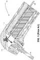
- FIG. 1illustrates a prior-art handpiece 100 comprising a waveguide 105that receives laser energy from the laser housing. The energy is transmitted through a window 110 and is reflected from a 90-degree mirror 115. Energy reflected from the mirror 115 is directed to a tip or ferrule 120 that directs the laser energy to the target surface.
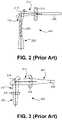
- FIGS. 2 and 3illustrate isolated elements of handpieces generally similar to that of FIG. 1 and demonstrate representative prior-art designs of laser handpieces.
- FIG. 2illustrates a device 200 comprising a waveguide 205 that emits laser energy and a flat window 210 through which the laser energy 212 is transmitted before reaching a concave reflector 215.
- Laser energy 217 reflected from the reflector 215enters a tip 220 whence laser energy 222 output from the tip 220 may be directed to a target surface.
- the device 200 illustrated in FIG. 2exhibits a diverging (e.g., spreading) of the laser energy 212 leaving the window 210.
- the concave reflector 215may mitigate an effect of the spreading laser energy 212 by focusing the laser energy 217 entering the tip 220, such compensation in the example still does not provide an adequate net correction, as the tip 220 in the example continues to emit diverging laser energy 222.
- FIG. 3it illustrates a prior-art device 300 comprising a waveguide 305 and a convex lens 310 that may reduce a diverging effect of laser energy 307 at the pre-reflector stage, directing laser energy 312 onto a flat reflector 315 from which laser energy 317 is directed through a flat window or tip 320 thereby producing laser energy 322 that can be focused onto a target, typically a few millimeters in front of the window 320.
- each of the devices illustrated in FIGS. 1-3is typically disposed very near, or even touching, the target surface owing to a shape and/or distribution of the electromagnetic laser energy emitted from an emitting surface of the device. Accordingly, back reflection of components from the target including, for example, fluids, particles, debris, energy (e.g., pressure waves), power-beam and/or visible light can reach the emitting surface, thereby degrading performance of the laser device.
- components from the targetincluding, for example, fluids, particles, debris, energy (e.g., pressure waves), power-beam and/or visible light
- DE 38 00 555 A1relates to a handheld device for treating tooth material with laser light and US 2007/190482 A1 relates to a laser cutting device with fluid supplied to the target site.
- a handpiece for laser tissue cuttingcomprising a window that receives electromagnetic energy, and a reflector that redirects the electromagnetic energy received from the window to a tip, the tip directing the electromagnetic energy received from the reflector to a target surface (e.g., or other chosen vicinity, such as an "interaction zone" defined in the below-referenced Pat. 5,574,247 ) at a distance (e.g., a selected distance) from an emitting surface of the tip.
- the selected distancemay be chosen to reduce back reflection of components from the target to the emitting surface to, near to, or below a level that negligibly impedes tissue cutting.
- an implementation of the invention herein disclosedfocuses the electromagnetic energy directed to the target surface at the selected distance.
- one or more of the window, reflector, and tipmay be adapted to provide a desired distribution of electromagnetic energy at the target surface (e.g., or other chosen vicinity).
- one or more of the window, reflector, and tipmay be adapted to provide a desired disruption, as a consequence of, inter alias, the electromagnetic energy at the target surface.
- the emitting surface of an embodiment of the inventionexhibits at least in part, and typically all of, the functionality of a converging lens.
- the handpiececomprises a fluid output adapted to emit fluid particles, whereby electromagnetic energy emitted from the emitting imparts energy into the fluid particles to thereby apply disruptive forces to the target surface.
- a beam guideadapted to facilitate spacing of the tip from the target surface.
- the present inventionmay be practiced in conjunction with various devices and techniques that are conventionally used in the art, and only so much of the commonly practiced process steps are included herein as are necessary to provide an understanding of the present invention.
- the present inventionhas applicability in the field of laser devices and processes in general. For illustrative purposes, however, the following description pertains to a laser cutting device.
- a laser handpiece 400comprising a waveguide 405, which may be, for example, an optical fiber, that receives electromagnetic energy (e.g., laser energy) from a laser source (not shown).
- a laser beam 407which comprises electromagnetic energy, may be emitted from the waveguide 405.
- a window 410may receive the laser beam 407 and may or may not shape the beam 407 into a modified laser beam 412 that impinges on a reflector 415.
- the reflector 415may further modify the laser beam 412 to produce another laser beam 417 that is coupled to a tip 420.
- the tip 420modifies the laser beam 417.
- the tip 420which typically may have a nominally cylindrical shape (but is not limited to such), operates as a lens to modify the laser beam 417.
- the tip 420converges the laser beam 417.
- the tip 420emits a laser beam 422 having a minimum cross- sectional width or "waist" (cf. portion of laser beam 22 indicated by arrowhead tip of lead line 422).
- the part of laser beam 422 shown with the smallest cross-sectional widthcorresponds to the focal point or peak-concentration part of the laser beam 422, and may be directed to a target surface to accomplish relatively high-power or focused cutting of, for example, tissue.
- FIG. 5Ais a schematic diagram of one embodiment of a laser handpiece designed according to the present invention.
- the illustrated embodimentcomprises a waveguide 505 that may provide functionality as described supra with reference to the waveguide 405 in FIG. 4 .
- the window 410 in the embodiment of FIG. 4may be implemented as a window 510 in the embodiment of FIG. 5A .
- the window 510may be formed of, for example, sapphire or glass transparent optical material, may or may not have an antireflective (AR) coating, and may be flat or lensed.
- ARantireflective
- the reflector 4may be implemented as a reflector 515 in the embodiment of FIG. 5A .
- the reflector 515e.g., a mirror
- the reflector 515may be formed of, for example, metal, ceramic material, sapphire, gold or other highly reflective (HR) material coated or plated for maximum reflection.
- HRhighly reflective
- Exemplary shapes of the reflector 515may include flat, toroidal, parabolic, and the like. For instance, in modified embodiments the reflector may resemble either of those shown in FIGS. 1 or 2 .
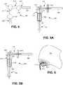
- the tip 420 of FIG. 4may be implemented as a tip 520 (that may be, for instance, a window) formed, for example, as a nominally cylindrical structure of, for example, one or more of sapphire and low OH glass.
- a typical tip 520may be (but is not limited to) a non-coated construction, and/or may have biconvex shapes 519 and 521 as illustrated.
- Representative dimensions of the tip 520may include a length ranging from about 2 mm to about 5 mm with a diameter ranging from about 1 mm to about 3 mm.
- FIG. 5Billustrates another variation on the theme of FIG. 4 , the embodiment of FIG. 4 being similar the embodiment of FIG. 5B with elements that evidently correspond to those of the embodiment of FIG. 4 .
- the embodiment of FIG. 5Bdiffers in that a single convex surface 621 is provided on an output of a tip 620, the input to the tip being implemented as a flat surface 619.
- the embodimentsmay generate output laser beams 522 and 622 that exhibit a minimum width portion or "waist" that can be designed to have specified dimensions (e.g., a distance from the tip 520/620 and/or a beam diameter at the waist) according to shapes and/or materials chosen for one or more of the window 510/610, the reflector 515/615, and the tip 520/620 in respective FIGS. 5A and 5B .
- specified dimensionse.g., a distance from the tip 520/620 and/or a beam diameter at the waist
- Control of parameters of the waistcan allow an improvement in high speed cutting of biological tissues (e.g., soft tissue, hard tissue, bone and/or hard tooth tissue) as compared with prior-art laser handpieces.
- a relatively long distancee.g., 5 or more, or, alternatively, 6 to 10 mm
- a relatively great distancee.g., more than 5 mm
- the output-tip emitting surface and the cutting tissue planecan advantageously or substantially reduce an amount of back reflection of, e.g., the power beam, back into the fiber emitting surface.
- the design(s) of this inventiontarget the achievement of one or more of high density and uniformity (i.e., an about uniform cross-section) of electromagnetic energy (e.g., laser) power at a selected and controlled distance from output tip emitting surface.
- electromagnetic energye.g., laser
- Another feature of the present inventionis to increase depth (e.g., to the target surface), wherein laser high-power density is kept relatively consistent at the increased depth.
- Inventive designs of laser handpiecesutilize converging-beam shapes and/or functions at or adjacent to the emitting surface of the output tip.
- the present inventionincorporates a modification of the shape of the emitting surface.
- Inventive designs of laser handpiecesadditionally and/or alternatively, may modify one, more than one, or all, of the other surfaces of the three optical elements (window, mirror and tip) to achieve, modify, control, and/or enhance the converging-beam function.
- the interrelation of the surfacesoperate to achieve rapid, non-contact (i.e., without direct contact between the output tip and tissue, or with increased-spacing) cutting.
- a relatively long distancee.g., 5 or more mm
- a relatively long distancee.g., 5 or more mm
- componentse.g., fluids, particles, debris, energy, power-beam and/or visible light
- an output tipis provided with an emitting surface that resembles and/or replicates a shape and/or functionality of a lens (e.g., that has a convex emitting surface 621 as shown in FIG. 5B ), and that provides one, more or all of the herein described advantages.
- the energy output of the inventive handpiececan, consequently, provide, for example, a desired beam distribution (e.g., with the beam focus point or the peak concentration of the beam) at the cutting area.
- the cutting areais spaced about 4to about 10mm, or, in particular and/or preferred examples, about 5 to about 7 mm, from the emitting surface. All three optical elements can be designed, in various combinations, to provide the desired beam distribution (e.g., a beam focus and/or a peak concentration of the beam) at the predetermined distances.
- the output tip 520/620is first constructed to have an output surface 521/621 in a shape of, and/or with the functionality of, a lens, and, subsequently, one or more of other surfaces (e.g., five surfaces including output end of trunk fiber, i.e., waveguide 505/605, surfaces of window 510/610 and reflector 515/615, and input 519/619 of tip 520/620), are designed to possess, e.g., one or more of a flat and a curved surface.
- other surfacese.g., five surfaces including output end of trunk fiber, i.e., waveguide 505/605, surfaces of window 510/610 and reflector 515/615, and input 519/619 of tip 520/620
- One of possible combinationsis to keep the window 510 not changed, make the reflector 515 (e.g., 90-degree mirror) flat and add convex surfaces 519 and 521 to both ends of the output tip 520 ( FIG. 5A ). These choices may allow creating a beam waist having a diameter nearly the same as the diameter of the original fiber, i.e., waveguide 505, at a certain (e.g., predefined, e.g., 5, 6 or 7 mm) distance away from the tip surface. In addition, that implementation may allow maintenance of a relatively high power density (e.g., and/or of no, or no significant, variation) at the certain distance (e.g., around the beam waist).
- a relatively high power densitye.g., and/or of no, or no significant, variation
- the output tipis interchangeable to allow switching between different output tips for functionality variation (e.g., of a converging characteristic performed on the beam, such as a change of the selected distance where the "waist" occurs and/or the width and/or cross-sectional shape and/or power density of the waist) and/or for cleaning /autoclaving.
- functionality variatione.g., of a converging characteristic performed on the beam, such as a change of the selected distance where the "waist" occurs and/or the width and/or cross-sectional shape and/or power density of the waist
- an embodiment of the laser handpiecemay be formed to include an (optional) "beam guide" 715, which may be affixed to a housing 705 that supports a tip (not shown) within tip ferrule 710 (cf. tip ferrule of FIG. 1 ) of a handpiece 700.
- the beam guide or reference arm added to the designmay comprise a straight, curved, spiral, or any other shape or shapes (e.g., of an elongate member or members) for facilitating spacing of the tip 710 from the tissue.
- the beam guide feature(s)may provide a visible and "feelable" reference to the location of the cutting area of the laser beam and/or a bottom of a cavity created by the cutting.
- the electromagnetic energy emitted by the handpiecemay comprise laser energy and/or visible light and may operate to provide or promote one or more of cutting, ablating, desterilization, bacterial reduction, biostimulation (e.g., low-level light therapy), coagulation, remodeling, caries detection ortreatment, and illumination (e.g., with visible light).
- biostimulatione.g., low-level light therapy
- coagulationcoagulation
- remodelinge.g., caries detection ortreatment
- illuminatione.g., with visible light
- the electromagnetic energycan comprise one or more of an electromagnetic energy source of ablation, and/or an electromagnetic energy source of illumination, and/or an electromagnetic energy source of tissue disruption, and/or an electromagnetic energy source of biostimulation.
- the target surfacemay comprise, for example, one or more of tooth tissue, bone, cartilage and soft tissue such as skin or nasal-cavity tissue.
- the energy outputcan comprise one or more of hard-tissue ablating electromagnetic energy, low-level light therapy (LLLT) electromagnetic energy, tissue-biostimulation electromagnetic energy, visible electromagnetic energy, coherent light, and electromagnetic energy generated by one or more of an Er:YAG laser, an Er:YSGG laser, an Er, a Cr:YSGG laser and a CTE:YAG laser.
- the energy outputcomprises one or more of a wavelength within a range from about 2.69 to about 2.80 microns and a wavelength of about 2.94 microns.
- a structuree.g., cannula(s) or orifice(s)
- a fluidcan be routed distally along an outer surface (e.g., the entire or substantially the entire outer surface, near the distal end) of the output tip.
- fluidmay be supplied through one or more gaps disposed between an outer surface of the waveguide (e.g., fiber optic) and the interior surface of a cannula.
- the fluidcan be a liquid or may comprise a combination of liquid and gas.
- the liquidis or comprises water, and in other implementations it is or comprises both air and water which, for example, can be mixed together either before or within the gap.
- the fluidcan comprise atomized fluid particles formed from a mixture of pressurized air and water and delivered through the gap to exit from the fluid output.
- a volume between the tissue ablating and/or tissue-treating distal end and the distal end of a cannulacan be transparent to a wavelength of energy emitted from the source of electromagnetic energy.
- a volume between (a) the tissue ablating and/or tissue- treating distal end and (b) the distal end of the cannuladoes not obstruct atomized fluid particles traveling in the direction from the fluid output to the distal end of the cannula.
- a volume between (a) the tissue ablating and/or tissue-treating distal end and (b) the target surfaceis not obstructed by any part of the apparatus.
- the apparatuscomprises a fluid output that is configured to emit fluid in a vicinity of the distal end of the apparatus, wherein: the fluid output may comprise an atomizer configured to place atomized fluid particles into a volume above the target surface. Further, the electromagnetic energy waveguide is configured to impart relatively large amounts of energy into the atomized fluid particles in the volume above the target surface to thereby expand the atomized fluid particles and impart disruptive forces onto the target surface.
- a medical handpieceincludes a handpiece housing and a source of electromagnetic energy disposed within the handpiece housing and adapted for emitting electromagnetic energy from a distal end of the handpiece housing.
- An illumination sourceis disposed within the handpiece housing for projecting light from the distal end of the handpiece housing onto a target surface.
- the illumination sourcemay include a fiber optic bundle.
- a medication linemay also be disposed within the handpiece housing for outputting medication through a distal end of the handpiece housing onto a target surface.
- laser energy from the trunk fiberis output from a power or treatment fiber, and is directed, for example, into fluid (e.g., an air and/or water spray or an atomized distribution of fluid particles from a water connection and/or a spray connection near an output end of a handpiece) that is emitted from the fluid output of the handpiece above a target surface (e.g., one or more of tooth, bone, cartilage and soft tissue).
- the fluid outputmay comprise a plurality of fluid outputs, concentrically arranged around a power fiber, as described in, for example, App. 11/042,824 and Prov. App. 60/601,415 .
- the power ortreatment fibermay be coupled to an electromagnetic energy source.
- the electromagnetic energy sourcecomprises one or more of a wavelength within a range from about 2.69 to about 2.80 microns and a wavelength of about 2.94 microns.
- the power fibermay be coupled to one or more of an Er:YAG laser, an Er:YSGG laser, an Er, Cr:YSGG laser and a CTE:YAG laser, and in particular instances may be coupled to one of an Er, Cr:YSGG solid state laser having a wavelength of about 2.789 microns and an Er:YAG solid state laser having a wavelength of about 2.940 microns.
- An apparatus including corresponding structure for directing electromagnetic energy into an atomized distribution of fluid particles above a target surfaceis disclosed, for example, in the below-referenced Pat. 5,574,247 , which describes the impartation of laser energy into fluid particles to thereby apply disruptive forces to the target surface.
- a laser assemblyhas been described that can output electromagnetic radiation useful to diagnose, monitor and/or affect a target surface.
- a probecan include one or more power or treatment fibers for transmitting treatment radiation to a target surface for treating (e.g., ablating) a dental structure, such as within a canal.
- the light for illumination and/or diagnosticsmay be transmitted simultaneously with, or intermittently with or separate from, transmission of treatment radiation and/or of the fluid from the fluid output or outputs.
- Such patentsinclude, but are not limited to Pat. 7,578,622 entitled Contra-angle rotating handpiece having tactile-feedback tip ferrule; Pat. 7,575,381 entitled Fiber tip detector apparatus and related methods; Pat. 7,563,226 entitled Handpieces having illumination and laser outputs; Pat. 7,467,946 entitled Electromagnetic radiation emitting toothbrush and dentifrice system; Pat. 7,461,982 entitled Contra-angle rotating handpiece having tactile-feedback tip ferrule; Pat. 7,461,658 entitled Methods for treating eye conditions; Pat. 7,458,380 entitled Methods for treating eye conditions; Pat. 7,424,199 entitled Fiber tip fluid output device; Pat. 7,421,186 entitled Modified-output fiber optic tips; Pat.
- Pat. 7,415,050entitled Electromagnetic energy distributions for electromagnetically induced mechanical cutting; Pat. 7,384,419 entitled Tapered fused waveguide for delivering treatment electromagnetic radiation toward a target surface; Pat. 7,356,208 entitled Fiber detector apparatus and related methods; Pat. 7,320,594 entitled Fluid and laser system; Pat. 7,303,397 entitled Caries detection using timing differentials between excitation and return pulses; Pat. 7,292,759 entitled Contra-angle rotating handpiece having tactile-feedback tip ferrule; Pat. 7,290,940 entitled Fiber tip detector apparatus and related methods; Pat. 7,288,086 entitled High-efficiency, side-pumped diode laser system; Pat. 7,270,657 entitled Radiation emitting apparatus with spatially controllable output energy distributions; Pat.
- App. Pub. 20090225060entitled Wrist-mounted laser with animated, page-based graphical user-interface
- App. Pub. 20090143775entitled Medical laser having controlled-temperature and sterilized fluid output
- App. Pub. 20090141752entitled Dual pulse-width medical laser with presets
- App. Pub. 20090105707entitled Drill and flavored fluid particles combination
- App. Pub. 20090104580entitled Fluid and pulsed energy output system
- App. Pub. 20080070185entitled Caries detection using timing differentials between excitation and return pulses; App. Pub. 20080069172 entitled Electromagnetic energy distributions for electromagnetically induced mechanical cutting; App. Pub. 20080065057 entitled High-efficiency, side-pumped diode laser system; App. Pub. 20080065055 entitled Methods for treating eye conditions; App. Pub. 20080065054 entitled Methods for treating hyperopia and presbyopia via laser tunneling; App. Pub. 20080065053 entitled Methods for treating eye conditions; App. Pub. 20080033411 entitled High efficiency electromagnetic laser energy cutting device; App. Pub. 20080033409 entitled Methods for treating eye conditions; App. Pub. 20080033407 entitled Methods for treating eye conditions; App. Pub.
- 20070184402entitled Caries detection using real-time imaging and multiple excitation frequencies; App. Pub. 20070128576 entitled Output attachments coded for use with electromagnetic-energy procedural device; App. Pub. 20070104419 entitled Fiber tip fluid output device; App. Pub. 20070060917 entitled High-efficiency, side-pumped diode laser system; App. Pub. 20070059660 entitled Device for dental care and whitening; App. Pub. 20070054236 entitled Device for dental care and whitening; App. Pub. 20070054235 entitled Device for dental care and whitening; App. Pub. 20070054233 entitled Device for dental care and whitening; App. Pub. 20070042315 entitled Visual feedback implements for electromagnetic energy output devices; App. Pub. 20070016176 entitled Laser handpiece architecture and methods; App.
- Pub. 20060204203entitled Radiation emitting apparatus with spatially controllable output energy distributions; App. Pub. 20060142745 entitled Dual pulse-width medical laser with presets; App. Pub. 20060142744 entitled Identification connector for a medical laser handpiece; App. Pub. 20060142743 entitled Medical laser having controlled-temperature and sterilized fluid output; App. Pub. 20060126680 entitled Dual pulse-width medical laser; App. Pub. 20060099548 entitled Caries detection using timing differentials between excitation and return pulses; App. Pub. 20060083466 entitled Fiber tip detector apparatus and related methods; App. Pub. 20060043903 entitled Electromagnetic energy distributions for electromagnetically induced mechanical cutting; App. Pub.
- any of the radiation outputse.g., lasers
- any of the fluid outputse.g., water outputs
- any conditioning agents, particles, agents, etc., and particulars or features thereof, or other features, including method steps and techniquesmay be used with any other structure(s) and process described or referenced herein, in whole or in part, in any combination or permutation as a non-equivalent, separate, non-interchangeable aspect of this invention.
Landscapes
- Health & Medical Sciences (AREA)
- Physics & Mathematics (AREA)
- Life Sciences & Earth Sciences (AREA)
- Surgery (AREA)
- Optics & Photonics (AREA)
- Veterinary Medicine (AREA)
- Public Health (AREA)
- General Health & Medical Sciences (AREA)
- Animal Behavior & Ethology (AREA)
- Molecular Biology (AREA)
- Electromagnetism (AREA)
- Medical Informatics (AREA)
- Biomedical Technology (AREA)
- Engineering & Computer Science (AREA)
- Otolaryngology (AREA)
- Nuclear Medicine, Radiotherapy & Molecular Imaging (AREA)
- Heart & Thoracic Surgery (AREA)
- Oral & Maxillofacial Surgery (AREA)
- Dentistry (AREA)
- Epidemiology (AREA)
- Laser Surgery Devices (AREA)
- Dental Tools And Instruments Or Auxiliary Dental Instruments (AREA)
- Cutting Tools, Boring Holders, And Turrets (AREA)
- Laser Beam Processing (AREA)
- Surgical Instruments (AREA)
Description
- The present invention relates generally to a laser cutting device for treating (e.g., cutting) hard and/or soft materials.
- A conventional medical handpiece comprises a waveguide (e.g., a fiber optic or trunk fiber) connected to a laser housing or module that provides electromagnetic (e.g., laser) energy that can be directed to a target surface such as bone or dental tissue by the handpiece in order to accomplish cutting of the tissue.
FIG. 1 illustrates a prior-art handpiece 100 comprising a waveguide 105that receives laser energy from the laser housing. The energy is transmitted through awindow 110 and is reflected from a 90-degree mirror 115. Energy reflected from themirror 115 is directed to a tip orferrule 120 that directs the laser energy to the target surface. FIGS. 2 and 3 illustrate isolated elements of handpieces generally similar to that ofFIG. 1 and demonstrate representative prior-art designs of laser handpieces.FIG. 2 illustrates adevice 200 comprising awaveguide 205 that emits laser energy and aflat window 210 through which thelaser energy 212 is transmitted before reaching aconcave reflector 215.Laser energy 217 reflected from thereflector 215 enters atip 220 whencelaser energy 222 output from thetip 220 may be directed to a target surface. Disadvantageously, thedevice 200 illustrated inFIG. 2 exhibits a diverging (e.g., spreading) of thelaser energy 212 leaving thewindow 210. To the extent theconcave reflector 215 may mitigate an effect of the spreadinglaser energy 212 by focusing thelaser energy 217 entering thetip 220, such compensation in the example still does not provide an adequate net correction, as thetip 220 in the example continues to emit diverginglaser energy 222.- Considering
FIG. 3 , it illustrates a prior-art device 300 comprising awaveguide 305 and aconvex lens 310 that may reduce a diverging effect oflaser energy 307 at the pre-reflector stage, directinglaser energy 312 onto aflat reflector 315 from whichlaser energy 317 is directed through a flat window ortip 320 thereby producinglaser energy 322 that can be focused onto a target, typically a few millimeters in front of thewindow 320. - In operation, each of the devices illustrated in
FIGS. 1-3 is typically disposed very near, or even touching, the target surface owing to a shape and/or distribution of the electromagnetic laser energy emitted from an emitting surface of the device.
Accordingly, back reflection of components from the target including, for example, fluids, particles, debris, energy (e.g., pressure waves), power-beam and/or visible light can reach the emitting surface, thereby degrading performance of the laser device. - A need thus exists in the prior art for a design architecture of a medical laser handpiece that can attenuate or eliminate the mentioned performance degradation, and enhance a speed of cutting (e.g., provide high speed cutting) of biological tissue relative to the mentioned constructions. A further need exists for a more reliable system for delivering electromagnetic energy to a target surface at a distance (e.g., a distance greater than required by the mentioned conventional devices) from an emitting surface that minimizes, reduces and/or eliminates harmful and/or undesirable (e.g., user detectable and/or device degrading) back reflection.
- Furthermore,
DE 38 00 555 A1 relates to a handheld device for treating tooth material with laser light andUS 2007/190482 A1 relates to a laser cutting device with fluid supplied to the target site. - The present invention addresses these needs by providing, according to an embodiment, a handpiece for laser tissue cutting comprising a window that receives electromagnetic energy, and a reflector that redirects the electromagnetic energy received from the window to a tip, the tip directing the electromagnetic energy received from the reflector to a target surface (e.g., or other chosen vicinity, such as an "interaction zone" defined in the below-referenced Pat.
5,574,247 - The emitting surface of an embodiment of the invention exhibits at least in part, and typically all of, the functionality of a converging lens.
- The handpiece comprises a fluid output adapted to emit fluid particles, whereby electromagnetic energy emitted from the emitting imparts energy into the fluid particles to thereby apply disruptive forces to the target surface. Another embodiment of the invention includes a beam guide adapted to facilitate spacing of the tip from the target surface.
- While the apparatus has or will be described for the sake of grammatical fluidity with functional explanations, it is to be expressly understood that the claims, unless indicated otherwise, are not to be construed as limited in any way by the construction of "means" or "steps" limitations, but are to be accorded the full scope of the meaning and equivalents of the definition provided by the claims under the judicial doctrine of equivalents.
- Any feature or combination of features described or referenced herein are included within the scope of the present invention provided that the features included in any such combination are not mutually inconsistent as will be apparent from the context, this specification, and the knowledge of one skilled in the art. For purposes of summarizing the present invention, certain aspects, advantages and novel features of the present invention are described or referenced. Of course, it is to be understood that not necessarily all such aspects, advantages or features will be embodied in any particular implementation of the present invention. Additional advantages and aspects of the present invention are apparent in the following detailed description and claims that follow.
FIG. 1 is a diagram of a prior-art laser handpiece;FIG. 2 is a schematic diagram of components of an example of a prior-art laser handpiece;FIG. 3 is a schematic diagram of components of another example of a prior-art laser handpiece;FIG. 4 is a schematic diagram of components of a laser handpiece according to the present invention;FIG. 5A is a schematic diagram of an embodiment of a laser handpiece architecture designed according to the present invention;FIG. 5B is a schematic diagram of components of another laser handpiece embodiment designed according to the present invention; andFIG. 6 is a pictorial diagram of an embodiment of a laser handpiece incorporating a beam guide.- Embodiments of the invention are now described and illustrated in the accompanying drawings, instances of which are to be interpreted to be to scale in some implementations while in other implementations, for each instance, not. In certain aspects, use of like or the same reference designators in the drawings and description refers to the same, similar or analogous components and/or elements, while according to other implementations the same use should not. According to certain implementations, use of directional terms, such as, top, bottom, left, right, up, down, over, above, below, beneath, rear, and front, are to be construed literally, while in other implementations the same use should not. The present invention may be practiced in conjunction with various devices and techniques that are conventionally used in the art, and only so much of the commonly practiced process steps are included herein as are necessary to provide an understanding of the present invention. The present invention has applicability in the field of laser devices and processes in general. For illustrative purposes, however, the following description pertains to a laser cutting device.
- With reference to
FIG. 4 , depicted therein is a schematic diagram of components of alaser handpiece 400 according to the present invention comprising awaveguide 405, which may be, for example, an optical fiber, that receives electromagnetic energy (e.g., laser energy) from a laser source (not shown). Alaser beam 407, which comprises electromagnetic energy, may be emitted from thewaveguide 405. Awindow 410 may receive thelaser beam 407 and may or may not shape thebeam 407 into a modifiedlaser beam 412 that impinges on areflector 415. Thereflector 415 may further modify thelaser beam 412 to produce anotherlaser beam 417 that is coupled to atip 420. - According to a feature of the present invention, the
tip 420 modifies thelaser beam 417. According to a further feature of the present invention, thetip 420, which typically may have a nominally cylindrical shape (but is not limited to such), operates as a lens to modify thelaser beam 417. According to yet another feature of the present invention, thetip 420 converges thelaser beam 417. - In the illustrated example, the
tip 420 emits alaser beam 422 having a minimum cross- sectional width or "waist" (cf. portion of laser beam 22 indicated by arrowhead tip of lead line 422). The part oflaser beam 422 shown with the smallest cross-sectional width corresponds to the focal point or peak-concentration part of thelaser beam 422, and may be directed to a target surface to accomplish relatively high-power or focused cutting of, for example, tissue. - Many variations on the theme of the
conceptual embodiment 400 may be designed by changing parameters of one or more of thewindow 410, thereflector 415, and thetip 420.FIG. 5A is a schematic diagram of one embodiment of a laser handpiece designed according to the present invention. The illustrated embodiment comprises awaveguide 505 that may provide functionality as describedsupra with reference to thewaveguide 405 inFIG. 4 . Thewindow 410 in the embodiment ofFIG. 4 may be implemented as awindow 510 in the embodiment ofFIG. 5A . Thewindow 510 may be formed of, for example, sapphire or glass transparent optical material, may or may not have an antireflective (AR) coating, and may be flat or lensed. Similarly, thereflector 415 inFIG. 4 may be implemented as areflector 515 in the embodiment ofFIG. 5A . The reflector 515 (e.g., a mirror) may be formed of, for example, metal, ceramic material, sapphire, gold or other highly reflective (HR) material coated or plated for maximum reflection. Exemplary shapes of thereflector 515 may include flat, toroidal, parabolic, and the like. For instance, in modified embodiments the reflector may resemble either of those shown inFIGS. 1 or2 . - The
tip 420 ofFIG. 4 may be implemented as a tip 520 (that may be, for instance, a window) formed, for example, as a nominally cylindrical structure of, for example, one or more of sapphire and low OH glass. Atypical tip 520 may be (but is not limited to) a non-coated construction, and/or may havebiconvex shapes tip 520 may include a length ranging from about 2 mm to about 5 mm with a diameter ranging from about 1 mm to about 3 mm. FIG. 5B illustrates another variation on the theme ofFIG. 4 , the embodiment ofFIG. 4 being similar the embodiment ofFIG. 5B with elements that evidently correspond to those of the embodiment ofFIG. 4 . The embodiment ofFIG. 5B differs in that a singleconvex surface 621 is provided on an output of atip 620, the input to the tip being implemented as aflat surface 619.- With continuing reference to the embodiments illustrated in
FIGS. 5A and 5B , the embodiments may generateoutput laser beams tip 520/620 and/or a beam diameter at the waist) according to shapes and/or materials chosen for one or more of thewindow 510/610, thereflector 515/615, and thetip 520/620 in respectiveFIGS. 5A and 5B . - Control of parameters of the waist can allow an improvement in high speed cutting of biological tissues (e.g., soft tissue, hard tissue, bone and/or hard tooth tissue) as compared with prior-art laser handpieces. Significantly increased reliability of the illustrated delivery systems (e.g.,
handpieces 500/600) due to an attenuation or complete absence of contact (e.g., direct contact), between thetip 521/621 (e.g., the emittingsurface 521/621 of the tip) and target tissue, whereby, for example, a relatively long distance (e.g., 5 or more, or, alternatively, 6 to 10 mm), between the output-tip emitting surface and the cutting tissue plane (i.e., between the emitting surface and the waist), can be created. For instance, a relatively great distance (e.g., more than 5 mm), between the output-tip emitting surface and the cutting tissue plane, can advantageously or substantially reduce an amount of back reflection of, e.g., the power beam, back into the fiber emitting surface. - One or more of these described effects on the beam path can be achieved by way of the new design of optical element(s) within the handpiece as described herein. The design(s) of this invention target the achievement of one or more of high density and uniformity (i.e., an about uniform cross-section) of electromagnetic energy (e.g., laser) power at a selected and controlled distance from output tip emitting surface. Another feature of the present invention is to increase depth (e.g., to the target surface), wherein laser high-power density is kept relatively consistent at the increased depth.
- Inventive designs of laser handpieces according to an aspect of the invention utilize converging-beam shapes and/or functions at or adjacent to the emitting surface of the output tip. Thus, the present invention incorporates a modification of the shape of the emitting surface. Inventive designs of laser handpieces additionally and/or alternatively, may modify one, more than one, or all, of the other surfaces of the three optical elements (window, mirror and tip) to achieve, modify, control, and/or enhance the converging-beam function. In all, or at least certain, combination(s), the interrelation of the surfaces operate to achieve rapid, non-contact (i.e., without direct contact between the output tip and tissue, or with increased-spacing) cutting. According to a contemplated configuration, a relatively long distance (e.g., 5 or more mm) can be maintained between the emitting surface of the output tip and the cutting tissue plane, thereby measurably, substantially, advantageously, and/or dramatically reducing the effect of back reflection of components (e.g., fluids, particles, debris, energy, power-beam and/or visible light) to or into emitting surface(s), the reflection of which may impede tissue cutting.
- According to one or more features of the invention, an output tip is provided with an emitting surface that resembles and/or replicates a shape and/or functionality of a lens (e.g., that has a convex emitting
surface 621 as shown inFIG. 5B ), and that provides one, more or all of the herein described advantages. The energy output of the inventive handpiece can, consequently, provide, for example, a desired beam distribution (e.g., with the beam focus point or the peak concentration of the beam) at the cutting area. The cutting area is spaced about 4to about 10mm, or, in particular and/or preferred examples, about 5 to about 7 mm, from the emitting surface. All three optical elements can be designed, in various combinations, to provide the desired beam distribution (e.g., a beam focus and/or a peak concentration of the beam) at the predetermined distances. - In a typical implementation of the invention, such as illustrated in
FIGS. 5A or 5B , theoutput tip 520/620 is first constructed to have anoutput surface 521/621 in a shape of, and/or with the functionality of, a lens, and, subsequently, one or more of other surfaces (e.g., five surfaces including output end of trunk fiber, i.e.,waveguide 505/605, surfaces ofwindow 510/610 andreflector 515/615, andinput 519/619 oftip 520/620), are designed to possess, e.g., one or more of a flat and a curved surface. - One of possible combinations is to keep the
window 510 not changed, make the reflector 515 (e.g., 90-degree mirror) flat and addconvex surfaces FIG. 5A ). These choices may allow creating a beam waist having a diameter nearly the same as the diameter of the original fiber, i.e.,waveguide 505, at a certain (e.g., predefined, e.g., 5, 6 or 7 mm) distance away from the tip surface. In addition, that implementation may allow maintenance of a relatively high power density (e.g., and/or of no, or no significant, variation) at the certain distance (e.g., around the beam waist). - According to one feature of the present invention, the output tip is interchangeable to allow switching between different output tips for functionality variation (e.g., of a converging characteristic performed on the beam, such as a change of the selected distance where the "waist" occurs and/or the width and/or cross-sectional shape and/or power density of the waist) and/or for cleaning /autoclaving. It is an advantage and difference compared to prior art (with protective window).
- According to another feature as illustrated in
FIG. 6 , as the tip is non-contact and works at a certain (e.g., predetermined) distance above the tissue, an embodiment of the laser handpiece may be formed to include an (optional) "beam guide" 715, which may be affixed to ahousing 705 that supports a tip (not shown) within tip ferrule 710 (cf. tip ferrule ofFIG. 1 ) of ahandpiece 700. The beam guide or reference arm added to the design may comprise a straight, curved, spiral, or any other shape or shapes (e.g., of an elongate member or members) for facilitating spacing of thetip 710 from the tissue. The beam guide feature(s) may provide a visible and "feelable" reference to the location of the cutting area of the laser beam and/or a bottom of a cavity created by the cutting. - The electromagnetic energy emitted by the handpiece may comprise laser energy and/or visible light and may operate to provide or promote one or more of cutting, ablating, desterilization, bacterial reduction, biostimulation (e.g., low-level light therapy), coagulation, remodeling, caries detection ortreatment, and illumination (e.g., with visible light).
- In certain implementations, the electromagnetic energy can comprise one or more of an electromagnetic energy source of ablation, and/or an electromagnetic energy source of illumination, and/or an electromagnetic energy source of tissue disruption, and/or an electromagnetic energy source of biostimulation.
- The target surface may comprise, for example, one or more of tooth tissue, bone, cartilage and soft tissue such as skin or nasal-cavity tissue.
- According to certain aspects of the present invention, the energy output can comprise one or more of hard-tissue ablating electromagnetic energy, low-level light therapy (LLLT) electromagnetic energy, tissue-biostimulation electromagnetic energy, visible electromagnetic energy, coherent light, and electromagnetic energy generated by one or more of an Er:YAG laser, an Er:YSGG laser, an Er, a Cr:YSGG laser and a CTE:YAG laser. The energy output comprises one or more of a wavelength within a range from about 2.69 to about 2.80 microns and a wavelength of about 2.94 microns.
- In one implementation, a structure (e.g., cannula(s) or orifice(s)) can be configured to direct liquid in a direction toward the distal end of the output tip. For example, a fluid can be routed distally along an outer surface (e.g., the entire or substantially the entire outer surface, near the distal end) of the output tip.
- In another implementation, fluid may be supplied through one or more gaps disposed between an outer surface of the waveguide (e.g., fiber optic) and the interior surface of a cannula. The fluid can be a liquid or may comprise a combination of liquid and gas. In certain implementations, the liquid is or comprises water, and in other implementations it is or comprises both air and water which, for example, can be mixed together either before or within the gap. For example, the fluid can comprise atomized fluid particles formed from a mixture of pressurized air and water and delivered through the gap to exit from the fluid output.
- A volume between the tissue ablating and/or tissue-treating distal end and the distal end of a cannula (e.g., holding the output tip and one, more, or all of the other operating components of the handpiece, in which case the handpiece is not a handpiece but rather is an intra-luminal, lipo, orjoint surgery device) can be transparent to a wavelength of energy emitted from the source of electromagnetic energy. According to another implementation, in addition to or as an alternative to the preceding features, a volume between (a) the tissue ablating and/or tissue- treating distal end and (b) the distal end of the cannula does not obstruct atomized fluid particles traveling in the direction from the fluid output to the distal end of the cannula. According to yet another implementation, in addition to or as an alternative to any one or more features set forth in this paragraph, a volume between (a) the tissue ablating and/or tissue-treating distal end and (b) the target surface is not obstructed by any part of the apparatus.
- The apparatus comprises a fluid output that is configured to emit fluid in a vicinity of the distal end of the apparatus, wherein: the fluid output may comprise an atomizer configured to place atomized fluid particles into a volume above the target surface. Further, the electromagnetic energy waveguide is configured to impart relatively large amounts of energy into the atomized fluid particles in the volume above the target surface to thereby expand the atomized fluid particles and impart disruptive forces onto the target surface.
- According to another aspect of the present invention, a medical handpiece includes a handpiece housing and a source of electromagnetic energy disposed within the handpiece housing and adapted for emitting electromagnetic energy from a distal end of the handpiece housing. An illumination source is disposed within the handpiece housing for projecting light from the distal end of the handpiece housing onto a target surface. The illumination source may include a fiber optic bundle. A medication line may also be disposed within the handpiece housing for outputting medication through a distal end of the handpiece housing onto a target surface.
- According to certain implementations, laser energy from the trunk fiber is output from a power or treatment fiber, and is directed, for example, into fluid (e.g., an air and/or water spray or an atomized distribution of fluid particles from a water connection and/or a spray connection near an output end of a handpiece) that is emitted from the fluid output of the handpiece above a target surface (e.g., one or more of tooth, bone, cartilage and soft tissue). The fluid output may comprise a plurality of fluid outputs, concentrically arranged around a power fiber, as described in, for example, App.
11/042,824 60/601,415 5,574,247 - By way of the disclosure herein, a laser assembly has been described that can output electromagnetic radiation useful to diagnose, monitor and/or affect a target surface. In the case of procedures using fiber optic tip radiation, a probe can include one or more power or treatment fibers for transmitting treatment radiation to a target surface for treating (e.g., ablating) a dental structure, such as within a canal. In any of the embodiments described herein, the light for illumination and/or diagnostics may be transmitted simultaneously with, or intermittently with or separate from, transmission of treatment radiation and/or of the fluid from the fluid output or outputs.
- Corresponding or related structure and methods are described in the following patents assigned to Biolase Technology, Inc., which include corresponding or related structure (and modifications thereof) which may be, in whole or in part, (i) operable with, (ii) modified by one skilled in the art to be operable with, and/or (iii) implemented/used with or in combination with, any part(s) of the present invention according to this disclosure, that of the patents or below applications, and the knowledge andjudgment of one skilled in the art.
- Such patents include, but are not limited to Pat.
7,578,622 7,575,381 7,563,226 7,467,946 7,461,982 7,461,658 7,458,380 7,424,199 7,421,186 7,415,050 7,384,419 7,356,208 7,320,594 7,303,397 7,292,759 7,290,940 7,288,086 7,270,657 7,261,558 7,194,180 7,187,822 7,144,249 7,108,693 7,068,912 6,942,658 6,829,427 6,821,272 6,744,790 6,669,685 6,616,451 6,616,447 6,610,053 6,567,582 6,561,803 6,544,256 6,533,775 6,389,193 6,350,123 6,288,499 6,254,597 6,231,567 6,086,367 5,968,037 5,785,521 5,741,247 - Also, the above disclosure and referenced items, and that described on the referenced pages, are intended to be operable or modifiable to be operable, in whole or in part, with corresponding or related structure and methods, in whole or in part, described in the following published applications and items referenced therein, which applications are listed as follows: App. Pub.
20090225060 20090143775 20090141752 20090105707 20090104580 20090076490 20090075229 20090067189 20090062779 20090056044 20090043364 20090042171 20090035717 20090031515 20080317429 20080276192 20080240172 20080221558 20080219629 20080212624 20080203280 20080181278 20080181261 20080157690 20080151953 20080138764 20080125677 20080125676 20080097418 20080097417 20080097416 20080070185 20080069172 20080065057 20080065055 20080065054 20080065053 20080033411 20080033409 20080033407 20080025675 20080025672 20080025671 20070298369 20070263975 20070258693 20070208404 20070208328 20070190482 20070184402 20070128576 20070104419 20070060917 20070059660 20070054236 20070054235 20070054233 20070042315 20070016176 20070014517 20070014322 20070009856 20070003604 20060281042 20060275016 20060241574 20060240381 20060210228 20060204203 20060142745 20060142744 20060142743 20060126680 20060099548 20060083466 20060043903 20050283143 20050281887 20050281530 20050256517 20050256516 20040106082 20040092925 20040091834 20040068256 20030228094 20020149324 20020014855
Although the disclosure herein refers to certain illustrated embodiments, it is to be understood that these embodiments have been presented by way of example rather than limitation. For example, any of the radiation outputs (e.g., lasers), any of the fluid outputs (e.g., water outputs), and any conditioning agents, particles, agents, etc., and particulars or features thereof, or other features, including method steps and techniques, may be used with any other structure(s) and process described or referenced herein, in whole or in part, in any combination or permutation as a non-equivalent, separate, non-interchangeable aspect of this invention. Corresponding or related structure and methods specifically contemplated, disclosed and claimed herein as part of this invention, to the extent not mutually inconsistent as will be apparent from the context, this specification, and the knowledge of one skilled in the art, including, modifications thereto, which may be, in whole or in part, (i) operable and/or constructed with, (ii) modified by one skilled in the art to be operable and/or constructed with, and/or (iii) implemented/made/used with or in combination with, any parts of the present invention according to this disclosure, include: (I) any one or more parts of the above disclosed or referenced structure and methods and/or (II) subject matter of any one or more of the following claims and parts thereof, in any permutation and/or combination. The intent accompanying this disclosure is to have such embodiments construed in conjunction with the knowledge of one skilled in the art to cover all modifications, variations, combinations, permutations, omissions, substitutions, alternatives, and equivalents of the embodiments, to the extent not mutually exclusive, as may fall within the scope of the invention as limited only by the appended claims.
Claims (10)
- A laser cutting device, comprisinga laser source with one or more of a wavelength within a range from about 2.69 to about 2.80 microns and a wavelength of about 2.94 microns; anda handpiece (400; 500; 600) for laser treating a tissue target surface, comprising:a window (410; 510; 610) coupled to receive electromagnetic energy from the laser source and output electromagnetic energy;a reflector (415; 515; 615) aligned to redirect electromagnetic energy outputted from the window; anda tip (420; 520; 620) positioned to receive electromagnetic energy from the reflector and shaped to generate an output of electromagnetic energy that is focused at a selected distance from an emitting surface (521; 621) of the tip, the tip including at least one convex surface and the selected distance ranging from about 4 mm to about 10 mm,further comprising a fluid output adapted to emit fluid particles, whereby electromagnetic energy emitted from the emitting surface (521; 621) imparts energy into the fluid particles to thereby apply disruptive forces to the target surface.
- The laser cutting device as set forth in claim 1, wherein the selected distance enables a reduction of the effect of back reflection of components from the tissue to the emitting surface.
- The laser cutting device as set forth in any one of claims 1 to 2, wherein one or more of the window (410; 510; 610), reflector (415; 515; 615), and tip (410; 520; 620) are adapted to provide a desired distribution of electromagnetic energy at the target surface.
- The laser cutting device as set forth in any one of claims 1 to 3, wherein the emitting surface exhibits functionality of a lens, preferably of a convex lens.
- The laser cutting device as set forth in any one of claims 1 to 4, further comprising a beam guide (715).
- The laser cutting device as set forth in any one of claims 1 to 5, further comprising a plurality of output tips having different beam-converging characteristics, wherein the tip comprises an output tip that is interchangeable with the other output tips.
- The laser cutting device as set forth in any one of claims 1 to 6, wherein:the window (410; 510; 610) comprises sapphire or glass transparent optical material;the reflector (415; 515; 615) comprises metal, ceramic material, or sapphire and has a flat, toroidal, or parabolic shape; and/orthe tip (521; 621) comprises sapphire or glass and has an approximately cylindrical shape.
- The laser cutting device as set forth in any one of claims 1 to 7, wherein the tip (521; 621) has a length ranging from about 2 mm to about 5 mm.
- The laser cutting device as set forth in any one of claims 1 to 8, wherein the tip (521; 621) has a diameter ranging from about 1 mm to about 3 mm.
- The laser cutting device as set forth in any one of claims 1 to 9, wherein reflecting surface of the reflector (415; 515; 615) has a flat shape.
Applications Claiming Priority (4)
| Application Number | Priority Date | Filing Date | Title |
|---|---|---|---|
| US11860908P | 2008-11-29 | 2008-11-29 | |
| US15644009P | 2009-02-27 | 2009-02-27 | |
| PCT/US2009/065950WO2010062969A1 (en) | 2008-11-29 | 2009-11-25 | Non-contact handpiece for laser tissue cutting |
| EP09829802.9AEP2370016B1 (en) | 2008-11-29 | 2009-11-25 | Laser treatment device with an emission tip for contactless use |
Related Parent Applications (2)
| Application Number | Title | Priority Date | Filing Date |
|---|---|---|---|
| EP09829802.9ADivisionEP2370016B1 (en) | 2008-11-29 | 2009-11-25 | Laser treatment device with an emission tip for contactless use |
| EP09829802.9ADivision-IntoEP2370016B1 (en) | 2008-11-29 | 2009-11-25 | Laser treatment device with an emission tip for contactless use |
Publications (2)
| Publication Number | Publication Date |
|---|---|
| EP3231385A1 EP3231385A1 (en) | 2017-10-18 |
| EP3231385B1true EP3231385B1 (en) | 2023-01-11 |
Family
ID=42223488
Family Applications (2)
| Application Number | Title | Priority Date | Filing Date |
|---|---|---|---|
| EP09829802.9AActiveEP2370016B1 (en) | 2008-11-29 | 2009-11-25 | Laser treatment device with an emission tip for contactless use |
| EP17170009.9AActiveEP3231385B1 (en) | 2008-11-29 | 2009-11-25 | Laser cutting device with an emission tip for contactless use |
Family Applications Before (1)
| Application Number | Title | Priority Date | Filing Date |
|---|---|---|---|
| EP09829802.9AActiveEP2370016B1 (en) | 2008-11-29 | 2009-11-25 | Laser treatment device with an emission tip for contactless use |
Country Status (8)
| Country | Link |
|---|---|
| US (3) | US8403922B2 (en) |
| EP (2) | EP2370016B1 (en) |
| JP (3) | JP2012510316A (en) |
| KR (1) | KR101266630B1 (en) |
| AU (1) | AU2009319746B2 (en) |
| CA (1) | CA2745016C (en) |
| ES (2) | ES2899977T3 (en) |
| WO (1) | WO2010062969A1 (en) |
Families Citing this family (21)
| Publication number | Priority date | Publication date | Assignee | Title |
|---|---|---|---|---|
| SI3311770T1 (en) | 2006-04-20 | 2023-11-30 | Sonendo, Inc. | Apparatus for treating root canals of teeth |
| US10835355B2 (en) | 2006-04-20 | 2020-11-17 | Sonendo, Inc. | Apparatus and methods for treating root canals of teeth |
| US7980854B2 (en) | 2006-08-24 | 2011-07-19 | Medical Dental Advanced Technologies Group, L.L.C. | Dental and medical treatments and procedures |
| US12114924B2 (en) | 2006-08-24 | 2024-10-15 | Pipstek, Llc | Treatment system and method |
| CN102724929B (en) | 2009-11-13 | 2016-04-13 | 索南多股份有限公司 | For liquid jet equipment and the method for dental treatment |
| CN103347462B (en) | 2010-10-21 | 2017-05-10 | 索南多股份有限公司 | Devices, methods and combinations for endodontics |
| CA2816106A1 (en)* | 2010-10-26 | 2012-05-03 | Biolase, Inc. | Collimating coupler for laser treatment devices |
| JP2013545308A (en) | 2010-11-04 | 2013-12-19 | バイオレイズ,インク. | Start-up sequence for ramp-up pulse power in medical lasers with high intensity leading sub-pulses |
| US11175462B2 (en)* | 2011-09-09 | 2021-11-16 | Boston Scientific Scimed, Inc. | Split surgical laser fiber |
| CN110623765A (en) | 2012-03-22 | 2019-12-31 | 索南多股份有限公司 | Apparatus and method for cleaning teeth |
| US10631962B2 (en) | 2012-04-13 | 2020-04-28 | Sonendo, Inc. | Apparatus and methods for cleaning teeth and gingival pockets |
| EP3943042B1 (en) | 2012-12-20 | 2024-03-13 | Sonendo, Inc. | Apparatus for cleaning teeth and root canals |
| US10363120B2 (en) | 2012-12-20 | 2019-07-30 | Sonendo, Inc. | Apparatus and methods for cleaning teeth and root canals |
| US10245181B2 (en)* | 2012-12-21 | 2019-04-02 | Alcon Research, Ltd. | Grin fiber multi-spot laser probe |
| EP2991576B1 (en) | 2013-05-01 | 2022-12-28 | Sonendo, Inc. | Apparatus and system for treating teeth |
| US9877801B2 (en) | 2013-06-26 | 2018-01-30 | Sonendo, Inc. | Apparatus and methods for filling teeth and root canals |
| KR101550414B1 (en) | 2015-05-22 | 2015-09-08 | 주식회사 비앤비시스템 | Dental laser device with direct connection between laser resonator and laser handpiece |
| KR102480573B1 (en)* | 2016-10-05 | 2022-12-23 | 바이오레이즈, 인크. | Dental systems and methods |
| JP2021520247A (en) | 2018-04-03 | 2021-08-19 | コンバージェント デンタル, インコーポレイテッド | Laser system for surgical applications |
| USD997355S1 (en) | 2020-10-07 | 2023-08-29 | Sonendo, Inc. | Dental treatment instrument |
| US11980415B2 (en) | 2020-12-11 | 2024-05-14 | Nuvasive, Inc. | Robotic surgery |
Citations (1)
| Publication number | Priority date | Publication date | Assignee | Title |
|---|---|---|---|---|
| US6190376B1 (en)* | 1996-12-10 | 2001-02-20 | Asah Medico A/S | Apparatus for tissue treatment |
Family Cites Families (94)
| Publication number | Priority date | Publication date | Assignee | Title |
|---|---|---|---|---|
| JPS5310193U (en)* | 1976-07-09 | 1978-01-27 | ||
| JPS597120B2 (en) | 1978-11-24 | 1984-02-16 | 日本電気株式会社 | speech analysis device |
| JPS6036253Y2 (en)* | 1981-03-03 | 1985-10-28 | 長田電機工業株式会社 | Dental medical laser handpiece |
| JPS581412U (en)* | 1981-06-26 | 1983-01-07 | 長田電機工業株式会社 | laser handpiece |
| EP0181864A1 (en)* | 1984-05-22 | 1986-05-28 | Surgical Laser Technologies Ohio, Inc. | Medical and surgical laser probe i |
| JPS63189143A (en)* | 1987-01-31 | 1988-08-04 | 持田製薬株式会社 | Focusing position guide device for laser scalpel |
| DE3800555A1 (en)* | 1988-01-12 | 1989-07-27 | Ulrich Dardenne Stiftung Ev | DEVICE FOR THE ABLATIVE PHOTODECOMPOSITION OF DENTAL RESIN SUBSTANCES BY MEANS OF A WAVELENGTH OF 193 NM ARGON / FLUORID EXCIMER LASERS AND AN APPLICATION DEVICE FOR THIS LASER LIGHTING DEVICE |
| US4917083A (en)* | 1988-03-04 | 1990-04-17 | Heraeus Lasersonics, Inc. | Delivery arrangement for a laser medical system |
| US5885082A (en) | 1988-12-21 | 1999-03-23 | Endo Technic International Corporation | Dental and medical procedures employing laser radiation |
| US4979180A (en)* | 1989-11-24 | 1990-12-18 | Muncheryan Arthur M | Modular interchangeable laser system |
| US5125923A (en)* | 1991-05-30 | 1992-06-30 | Sorenson Laboratories, Inc. | Laser surgical instrument |
| US5374266A (en) | 1991-11-27 | 1994-12-20 | Kabushiki Kaisha Morita Seisakusho | Medical laser treatment device |
| US5370643A (en)* | 1992-07-06 | 1994-12-06 | Ceramoptec, Inc. | Multiple effect laser delivery device and system for medical procedures |
| JPH0799162A (en) | 1993-06-21 | 1995-04-11 | Hitachi Ltd | CVD reactor device |
| US6567582B1 (en) | 1995-08-31 | 2003-05-20 | Biolase Tech Inc | Fiber tip fluid output device |
| US20090105707A1 (en) | 1995-08-31 | 2009-04-23 | Rizoiu Ioana M | Drill and flavored fluid particles combination |
| US20090143775A1 (en) | 1995-08-31 | 2009-06-04 | Rizoiu Ioana M | Medical laser having controlled-temperature and sterilized fluid output |
| US20060142743A1 (en) | 2004-07-27 | 2006-06-29 | Rizoiu Ioana M | Medical laser having controlled-temperature and sterilized fluid output |
| US20050281887A1 (en) | 1995-08-31 | 2005-12-22 | Rizoiu Ioana M | Fluid conditioning system |
| US6389193B1 (en) | 1998-12-22 | 2002-05-14 | Biolase Technology, Inc. | Rotating handpiece |
| US7620290B2 (en) | 1995-08-31 | 2009-11-17 | Biolase Technology, Inc. | Modified-output fiber optic tips |
| US5741247A (en) | 1995-08-31 | 1998-04-21 | Biolase Technology, Inc. | Atomized fluid particles for electromagnetically induced cutting |
| US7320594B1 (en) | 1995-08-31 | 2008-01-22 | Biolase Technology, Inc. | Fluid and laser system |
| US6350123B1 (en) | 1995-08-31 | 2002-02-26 | Biolase Technology, Inc. | Fluid conditioning system |
| US6254597B1 (en) | 1995-08-31 | 2001-07-03 | Biolase Technology, Inc. | Tissue remover and method |
| US5785521A (en) | 1995-08-31 | 1998-07-28 | Biolase Technology, Inc. | Fluid conditioning system |
| US7187822B2 (en) | 1995-08-31 | 2007-03-06 | Biolase Technology, Inc. | Fiber tip fluid output device |
| US20060241574A1 (en) | 1995-08-31 | 2006-10-26 | Rizoiu Ioana M | Electromagnetic energy distributions for electromagnetically induced disruptive cutting |
| US20060240381A1 (en) | 1995-08-31 | 2006-10-26 | Biolase Technology, Inc. | Fluid conditioning system |
| US6669685B1 (en) | 1997-11-06 | 2003-12-30 | Biolase Technology, Inc. | Tissue remover and method |
| US20070190482A1 (en) | 2003-05-09 | 2007-08-16 | Rizoiu Ioana M | Fluid conditioning system |
| US6288499B1 (en) | 1997-06-12 | 2001-09-11 | Biolase Technology, Inc. | Electromagnetic energy distributions for electromagnetically induced mechanical cutting |
| US20070208328A1 (en) | 1995-08-31 | 2007-09-06 | Dmitri Boutoussov | Contra-angel rotating handpiece having tactile-feedback tip ferrule |
| US6744790B1 (en) | 1995-08-31 | 2004-06-01 | Biolase Technology, Inc. | Device for reduction of thermal lensing |
| US6231567B1 (en) | 1995-08-31 | 2001-05-15 | Biolase Technology Inc. | Material remover and method |
| JP2869862B2 (en)* | 1996-04-01 | 1999-03-10 | 株式会社エス・エル・ティ・ジャパン | Target for laser treatment of living tissue |
| DE19636265B4 (en) | 1996-09-06 | 2007-09-20 | Kaltenbach & Voigt Gmbh | laser instrument |
| US7204832B2 (en)* | 1996-12-02 | 2007-04-17 | Pálomar Medical Technologies, Inc. | Cooling system for a photo cosmetic device |
| EP0996388B1 (en) | 1997-06-20 | 2008-09-10 | Biolase Technology, Inc. | Electromagnetic radiation emitting toothbrush and dentifrice system |
| US6074382A (en)* | 1997-08-29 | 2000-06-13 | Asah Medico A/S | Apparatus for tissue treatment |
| US6544256B1 (en) | 1998-04-24 | 2003-04-08 | Biolase Technology, Inc. | Electromagnetically induced cutting with atomized fluid particles for dermatological applications |
| JP2000023999A (en)* | 1998-07-16 | 2000-01-25 | Morita Mfg Co Ltd | Chisel laser probe |
| US6333485B1 (en)* | 1998-12-11 | 2001-12-25 | International Business Machines Corporation | Method for minimizing sample damage during the ablation of material using a focused ultrashort pulsed beam |
| US6533775B1 (en) | 1999-05-05 | 2003-03-18 | Ioana M. Rizoiu | Light-activated hair treatment and removal device |
| US6451010B1 (en)* | 2000-04-14 | 2002-09-17 | Lumenis Inc. | Zoom handpiece for laser surgery |
| US6829427B1 (en) | 2000-10-24 | 2004-12-07 | Biolase Technology, Inc. | Fiber detector apparatus and related methods |
| US20070054233A1 (en) | 2003-07-22 | 2007-03-08 | Biolase Technology, Inc. | Device for dental care and whitening |
| US6616447B1 (en) | 2000-11-15 | 2003-09-09 | Biolase Technology, Inc. | Device for dental care and whitening |
| US20080157690A1 (en) | 2001-05-02 | 2008-07-03 | Biolase Technology, Inc. | Electromagnetic energy distributions for electromagnetically induced mechanical cutting |
| US7288086B1 (en) | 2001-06-21 | 2007-10-30 | Biolase Technology, Inc. | High-efficiency, side-pumped diode laser system |
| US6942658B1 (en) | 2001-08-24 | 2005-09-13 | Boilase Technology, Inc. | Radiation emitting apparatus with spatially controllable output energy distributions |
| US7384419B2 (en) | 2002-08-26 | 2008-06-10 | Biolase Technology, Inc. | Tapered fused waveguide for delivering treatment electromagnetic radiation toward a target surfaced |
| US7303578B2 (en)* | 2001-11-01 | 2007-12-04 | Photothera, Inc. | Device and method for providing phototherapy to the brain |
| US20070060917A1 (en) | 2002-06-21 | 2007-03-15 | Biolase Technology, Inc. | High-efficiency, side-pumped diode laser system |
| EP1732646B1 (en) | 2004-01-08 | 2011-09-07 | BioLase Technology, Inc. | Illumination device and related methods |
| US20080219629A1 (en) | 2004-01-08 | 2008-09-11 | Blolase Technology, Inc. | Modified-output fiber optic tips |
| SI2329785T1 (en) | 2004-01-22 | 2013-07-31 | Biolase, Inc. | Electromagnetically induced treatment devices |
| EP1782116A4 (en) | 2004-07-13 | 2009-01-21 | Biolase Tech Inc | Fiber tip detector apparatus and related methods |
| US7461982B2 (en) | 2004-07-20 | 2008-12-09 | Biolase Technology, Inc. | Contra-angle rotating handpiece having tactile-feedback tip ferrule |
| US7292759B2 (en) | 2005-06-07 | 2007-11-06 | Biolase Technology, Inc. | Contra-angle rotating handpiece having tactile-feedback tip ferrule |
| JP2008508034A (en)* | 2004-07-27 | 2008-03-21 | バイオレーズ テクノロジー インコーポレイテッド | Contra-angle rotating handpiece with tactile feedback tip ferrule |
| US20060142744A1 (en) | 2004-07-27 | 2006-06-29 | Dmitri Boutoussov | Identification connector for a medical laser handpiece |
| US7970030B2 (en) | 2004-07-27 | 2011-06-28 | Biolase Technology, Inc. | Dual pulse-width medical laser with presets |
| US20060142745A1 (en) | 2004-08-13 | 2006-06-29 | Dmitri Boutoussov | Dual pulse-width medical laser with presets |
| EP2638876B1 (en) | 2004-08-13 | 2016-12-07 | Biolase, Inc. | Laser handpiece architecture and methods |
| ES2405829T3 (en) | 2004-08-13 | 2013-06-04 | Biolase, Inc. | Caries detection using time differentials between excitation and return impulses |
| US20060095096A1 (en)* | 2004-09-09 | 2006-05-04 | Debenedictis Leonard C | Interchangeable tips for medical laser treatments and methods for using same |
| AU2005284745A1 (en) | 2004-09-18 | 2006-03-23 | Biolase Technology, Inc. | Output attachments coded for use with electromagnetic-energy procedural device |
| US20060129141A1 (en) | 2004-12-10 | 2006-06-15 | Lin J T | Treatment of eye disorders using articulated-arm coupled ultraviolet lasers |
| US7421186B2 (en) | 2005-01-10 | 2008-09-02 | Biolase Technology, Inc. | Modified-output fiber optic tips |
| EP1879517A4 (en) | 2005-04-22 | 2008-08-06 | Biolase Tech Inc | Methods for treating hyperopia and presbyopia via laser tunneling |
| JP2008539036A (en) | 2005-04-26 | 2008-11-13 | バイオレーズ テクノロジー インコーポレイテッド | Device for treating ocular symptoms |
| BRPI0610383A2 (en) | 2005-05-18 | 2010-06-15 | Biolase Tech Inc | toothbrush and dentifrice system with electromagnetic radiation emission |
| EP1883381A4 (en) | 2005-05-25 | 2010-03-17 | Biolase Tech Inc | Electromagnetic energy emitting device with increased spot size |
| WO2006128021A2 (en) | 2005-05-25 | 2006-11-30 | Biolase Technology, Inc. | Device having activated textured surfaces for treating oral tissue |
| WO2006133065A2 (en) | 2005-06-03 | 2006-12-14 | Biolase Technology, Inc. | Tissue treatment device and method |
| US20090067189A1 (en) | 2005-06-07 | 2009-03-12 | Dmitri Boutoussov | Contra-angle rotating handpiece having tactile-feedback tip ferrule |
| WO2006138723A2 (en) | 2005-06-16 | 2006-12-28 | Biolase Technology, Inc. | Tissue coverings bearing cutomized tissue images |
| AU2006261683B2 (en) | 2005-06-24 | 2010-07-08 | Biolase, Inc. | Visual feedback implements for electromagnetic energy output devices |
| US20070100401A1 (en)* | 2005-11-01 | 2007-05-03 | Lin J T | Compact laser device and method for hair removal |
| WO2007079433A2 (en) | 2006-01-03 | 2007-07-12 | Biolase Technology, Inc. | Caries detection using real-time imaging and multiple excitation frequencies |
| US8256431B2 (en) | 2006-04-24 | 2012-09-04 | Biolase, Inc. | Methods for treating hyperopia and presbyopia via laser tunneling |
| US8544473B2 (en) | 2006-04-26 | 2013-10-01 | Biolase, Inc. | Methods for treating eye conditions with low-level light therapy |
| US7356208B2 (en) | 2006-05-03 | 2008-04-08 | Biolase Technology, Inc. | Fiber detector apparatus and related methods |
| US20080033411A1 (en) | 2006-07-14 | 2008-02-07 | Biolase Technology, Inc. | High efficiency electromagnetic laser energy cutting device |
| US7415050B2 (en) | 2006-09-18 | 2008-08-19 | Biolase Technology, Inc. | Electromagnetic energy distributions for electromagnetically induced mechanical cutting |
| US7815630B2 (en) | 2007-01-25 | 2010-10-19 | Biolase Technology, Inc. | Target-close electromagnetic energy emitting device |
| US7695469B2 (en) | 2007-01-25 | 2010-04-13 | Biolase Technology, Inc. | Electromagnetic energy output system |
| US9101377B2 (en) | 2007-01-25 | 2015-08-11 | Biolase, Inc. | Electromagnetic energy output system |
| US20080276192A1 (en) | 2007-05-03 | 2008-11-06 | Biolase Technology, Inc. | Method and apparatus for controlling an electromagnetic energy output system |
| US20090225060A1 (en) | 2007-05-03 | 2009-09-10 | Rizoiu Ioana M | Wrist-mounted laser with animated, page-based graphical user-interface |
| WO2008157715A2 (en) | 2007-06-19 | 2008-12-24 | Biolase Technology, Inc. | Fluid controllable laser endodontic cleaning and disinfecting system |
| CA2704732C (en) | 2007-09-19 | 2012-04-24 | Biolase Technology, Inc. | Probes and biofluids for treating and removing deposits from tissue surfaces |
| US9553422B2 (en)* | 2009-08-04 | 2017-01-24 | Medical Coherence Llc | Multiple aperture hand-held laser therapy apparatus |
- 2009
- 2009-11-25WOPCT/US2009/065950patent/WO2010062969A1/enactiveApplication Filing
- 2009-11-25USUS12/626,271patent/US8403922B2/enactiveActive
- 2009-11-25KRKR1020117014883Apatent/KR101266630B1/enactiveActive
- 2009-11-25ESES09829802Tpatent/ES2899977T3/enactiveActive
- 2009-11-25CACA2745016Apatent/CA2745016C/ennot_activeExpired - Fee Related
- 2009-11-25EPEP09829802.9Apatent/EP2370016B1/enactiveActive
- 2009-11-25AUAU2009319746Apatent/AU2009319746B2/ennot_activeCeased
- 2009-11-25ESES17170009Tpatent/ES2938218T3/enactiveActive
- 2009-11-25EPEP17170009.9Apatent/EP3231385B1/enactiveActive
- 2009-11-25JPJP2011538691Apatent/JP2012510316A/enactivePending
- 2013
- 2013-03-11USUS13/793,026patent/US20130190743A1/ennot_activeAbandoned
- 2013-10-07JPJP2013210584Apatent/JP5848740B2/enactiveActive
- 2015
- 2015-01-05USUS14/589,764patent/US20150126984A1/ennot_activeAbandoned
- 2015-11-26JPJP2015231059Apatent/JP2016027931A/enactivePending
Patent Citations (1)
| Publication number | Priority date | Publication date | Assignee | Title |
|---|---|---|---|---|
| US6190376B1 (en)* | 1996-12-10 | 2001-02-20 | Asah Medico A/S | Apparatus for tissue treatment |
Also Published As
| Publication number | Publication date |
|---|---|
| EP2370016A1 (en) | 2011-10-05 |
| EP3231385A1 (en) | 2017-10-18 |
| US8403922B2 (en) | 2013-03-26 |
| US20150126984A1 (en) | 2015-05-07 |
| AU2009319746A1 (en) | 2011-07-21 |
| EP2370016B1 (en) | 2021-10-06 |
| AU2009319746B2 (en) | 2013-08-15 |
| JP2014061390A (en) | 2014-04-10 |
| ES2938218T3 (en) | 2023-04-05 |
| US20130190743A1 (en) | 2013-07-25 |
| CA2745016C (en) | 2017-02-21 |
| ES2899977T3 (en) | 2022-03-15 |
| JP2012510316A (en) | 2012-05-10 |
| KR101266630B1 (en) | 2013-05-22 |
| US20100137852A1 (en) | 2010-06-03 |
| CA2745016A1 (en) | 2010-06-03 |
| JP2016027931A (en) | 2016-02-25 |
| WO2010062969A1 (en) | 2010-06-03 |
| JP5848740B2 (en) | 2016-01-27 |
| EP2370016A4 (en) | 2012-06-06 |
| KR20110100238A (en) | 2011-09-09 |
Similar Documents
| Publication | Publication Date | Title |
|---|---|---|
| EP3231385B1 (en) | Laser cutting device with an emission tip for contactless use | |
| US5415652A (en) | Method and apparatus for the treatment of hard biological material, such as hard dental material using lasers | |
| EP2636109B1 (en) | Initiation sequences for ramping-up pulse power in a medical laser having high-intensity leading subpulses | |
| EP1799404B1 (en) | Contra-angle rotating handpiece having tactile-feedback tip ferrule | |
| US7563226B2 (en) | Handpieces having illumination and laser outputs | |
| US7461982B2 (en) | Contra-angle rotating handpiece having tactile-feedback tip ferrule | |
| US5458594A (en) | Method and apparatus for the treatment of hard biological material, such as hard dental material, using lasers | |
| JPH11502130A (en) | Apparatus used for laser treatment of living tissue | |
| US20090067189A1 (en) | Contra-angle rotating handpiece having tactile-feedback tip ferrule | |
| KR20080016613A (en) | Electromagnetic energy emitter with increased spot size | |
| EP0591129A1 (en) | Dental laser assembly with dual lasers | |
| US20100125291A1 (en) | Drill and flavored fluid particles combination | |
| US20090275935A1 (en) | Cannula enclosing recessed waveguide output tip | |
| US20120099815A1 (en) | Collimating coupler for laser treatment devices | |
| EP3958784B1 (en) | System and device for treatment of periodontic pockets using disposable inserts | |
| US20150238261A1 (en) | System and method for treatment using a laser beam delivered via an optical fiber | |
| US20080306473A1 (en) | Tissue-treating device with medium-control mechanism |
Legal Events
| Date | Code | Title | Description |
|---|---|---|---|
| PUAI | Public reference made under article 153(3) epc to a published international application that has entered the european phase | Free format text:ORIGINAL CODE: 0009012 | |
| STAA | Information on the status of an ep patent application or granted ep patent | Free format text:STATUS: THE APPLICATION HAS BEEN PUBLISHED | |
| AC | Divisional application: reference to earlier application | Ref document number:2370016 Country of ref document:EP Kind code of ref document:P | |
| AK | Designated contracting states | Kind code of ref document:A1 Designated state(s):AT BE BG CH CY CZ DE DK EE ES FI FR GB GR HR HU IE IS IT LI LT LU LV MC MK MT NL NO PL PT RO SE SI SK SM TR | |
| STAA | Information on the status of an ep patent application or granted ep patent | Free format text:STATUS: REQUEST FOR EXAMINATION WAS MADE | |
| 17P | Request for examination filed | Effective date:20180418 | |
| RBV | Designated contracting states (corrected) | Designated state(s):AT BE BG CH CY CZ DE DK EE ES FI FR GB GR HR HU IE IS IT LI LT LU LV MC MK MT NL NO PL PT RO SE SI SK SM TR | |
| STAA | Information on the status of an ep patent application or granted ep patent | Free format text:STATUS: EXAMINATION IS IN PROGRESS | |
| 17Q | First examination report despatched | Effective date:20210225 | |
| GRAP | Despatch of communication of intention to grant a patent | Free format text:ORIGINAL CODE: EPIDOSNIGR1 | |
| STAA | Information on the status of an ep patent application or granted ep patent | Free format text:STATUS: GRANT OF PATENT IS INTENDED | |
| INTG | Intention to grant announced | Effective date:20220722 | |
| GRAS | Grant fee paid | Free format text:ORIGINAL CODE: EPIDOSNIGR3 | |
| GRAA | (expected) grant | Free format text:ORIGINAL CODE: 0009210 | |
| STAA | Information on the status of an ep patent application or granted ep patent | Free format text:STATUS: THE PATENT HAS BEEN GRANTED | |
| AC | Divisional application: reference to earlier application | Ref document number:2370016 Country of ref document:EP Kind code of ref document:P | |
| AK | Designated contracting states | Kind code of ref document:B1 Designated state(s):AT BE BG CH CY CZ DE DK EE ES FI FR GB GR HR HU IE IS IT LI LT LU LV MC MK MT NL NO PL PT RO SE SI SK SM TR | |
| REG | Reference to a national code | Ref country code:GB Ref legal event code:FG4D | |
| REG | Reference to a national code | Ref country code:CH Ref legal event code:EP | |
| REG | Reference to a national code | Ref country code:DE Ref legal event code:R096 Ref document number:602009064739 Country of ref document:DE | |
| REG | Reference to a national code | Ref country code:IE Ref legal event code:FG4D | |
| REG | Reference to a national code | Ref country code:AT Ref legal event code:REF Ref document number:1542949 Country of ref document:AT Kind code of ref document:T Effective date:20230215 | |
| REG | Reference to a national code | Ref country code:ES Ref legal event code:FG2A Ref document number:2938218 Country of ref document:ES Kind code of ref document:T3 Effective date:20230405 | |
| REG | Reference to a national code | Ref country code:LT Ref legal event code:MG9D | |
| REG | Reference to a national code | Ref country code:NL Ref legal event code:MP Effective date:20230111 | |
| REG | Reference to a national code | Ref country code:AT Ref legal event code:MK05 Ref document number:1542949 Country of ref document:AT Kind code of ref document:T Effective date:20230111 | |
| PG25 | Lapsed in a contracting state [announced via postgrant information from national office to epo] | Ref country code:NL Free format text:LAPSE BECAUSE OF FAILURE TO SUBMIT A TRANSLATION OF THE DESCRIPTION OR TO PAY THE FEE WITHIN THE PRESCRIBED TIME-LIMIT Effective date:20230111 | |
| P01 | Opt-out of the competence of the unified patent court (upc) registered | Effective date:20230526 | |
| PG25 | Lapsed in a contracting state [announced via postgrant information from national office to epo] | Ref country code:PT Free format text:LAPSE BECAUSE OF FAILURE TO SUBMIT A TRANSLATION OF THE DESCRIPTION OR TO PAY THE FEE WITHIN THE PRESCRIBED TIME-LIMIT Effective date:20230511 Ref country code:NO Free format text:LAPSE BECAUSE OF FAILURE TO SUBMIT A TRANSLATION OF THE DESCRIPTION OR TO PAY THE FEE WITHIN THE PRESCRIBED TIME-LIMIT Effective date:20230411 Ref country code:LV Free format text:LAPSE BECAUSE OF FAILURE TO SUBMIT A TRANSLATION OF THE DESCRIPTION OR TO PAY THE FEE WITHIN THE PRESCRIBED TIME-LIMIT Effective date:20230111 Ref country code:LT Free format text:LAPSE BECAUSE OF FAILURE TO SUBMIT A TRANSLATION OF THE DESCRIPTION OR TO PAY THE FEE WITHIN THE PRESCRIBED TIME-LIMIT Effective date:20230111 Ref country code:HR Free format text:LAPSE BECAUSE OF FAILURE TO SUBMIT A TRANSLATION OF THE DESCRIPTION OR TO PAY THE FEE WITHIN THE PRESCRIBED TIME-LIMIT Effective date:20230111 Ref country code:AT Free format text:LAPSE BECAUSE OF FAILURE TO SUBMIT A TRANSLATION OF THE DESCRIPTION OR TO PAY THE FEE WITHIN THE PRESCRIBED TIME-LIMIT Effective date:20230111 | |
| PG25 | Lapsed in a contracting state [announced via postgrant information from national office to epo] | Ref country code:SE Free format text:LAPSE BECAUSE OF FAILURE TO SUBMIT A TRANSLATION OF THE DESCRIPTION OR TO PAY THE FEE WITHIN THE PRESCRIBED TIME-LIMIT Effective date:20230111 Ref country code:PL Free format text:LAPSE BECAUSE OF FAILURE TO SUBMIT A TRANSLATION OF THE DESCRIPTION OR TO PAY THE FEE WITHIN THE PRESCRIBED TIME-LIMIT Effective date:20230111 Ref country code:IS Free format text:LAPSE BECAUSE OF FAILURE TO SUBMIT A TRANSLATION OF THE DESCRIPTION OR TO PAY THE FEE WITHIN THE PRESCRIBED TIME-LIMIT Effective date:20230511 Ref country code:GR Free format text:LAPSE BECAUSE OF FAILURE TO SUBMIT A TRANSLATION OF THE DESCRIPTION OR TO PAY THE FEE WITHIN THE PRESCRIBED TIME-LIMIT Effective date:20230412 Ref country code:FI Free format text:LAPSE BECAUSE OF FAILURE TO SUBMIT A TRANSLATION OF THE DESCRIPTION OR TO PAY THE FEE WITHIN THE PRESCRIBED TIME-LIMIT Effective date:20230111 | |
| REG | Reference to a national code | Ref country code:DE Ref legal event code:R097 Ref document number:602009064739 Country of ref document:DE | |
| PG25 | Lapsed in a contracting state [announced via postgrant information from national office to epo] | Ref country code:SM Free format text:LAPSE BECAUSE OF FAILURE TO SUBMIT A TRANSLATION OF THE DESCRIPTION OR TO PAY THE FEE WITHIN THE PRESCRIBED TIME-LIMIT Effective date:20230111 Ref country code:RO Free format text:LAPSE BECAUSE OF FAILURE TO SUBMIT A TRANSLATION OF THE DESCRIPTION OR TO PAY THE FEE WITHIN THE PRESCRIBED TIME-LIMIT Effective date:20230111 Ref country code:EE Free format text:LAPSE BECAUSE OF FAILURE TO SUBMIT A TRANSLATION OF THE DESCRIPTION OR TO PAY THE FEE WITHIN THE PRESCRIBED TIME-LIMIT Effective date:20230111 Ref country code:DK Free format text:LAPSE BECAUSE OF FAILURE TO SUBMIT A TRANSLATION OF THE DESCRIPTION OR TO PAY THE FEE WITHIN THE PRESCRIBED TIME-LIMIT Effective date:20230111 Ref country code:CZ Free format text:LAPSE BECAUSE OF FAILURE TO SUBMIT A TRANSLATION OF THE DESCRIPTION OR TO PAY THE FEE WITHIN THE PRESCRIBED TIME-LIMIT Effective date:20230111 | |
| PLBE | No opposition filed within time limit | Free format text:ORIGINAL CODE: 0009261 | |
| STAA | Information on the status of an ep patent application or granted ep patent | Free format text:STATUS: NO OPPOSITION FILED WITHIN TIME LIMIT | |
| PG25 | Lapsed in a contracting state [announced via postgrant information from national office to epo] | Ref country code:SK Free format text:LAPSE BECAUSE OF FAILURE TO SUBMIT A TRANSLATION OF THE DESCRIPTION OR TO PAY THE FEE WITHIN THE PRESCRIBED TIME-LIMIT Effective date:20230111 | |
| 26N | No opposition filed | Effective date:20231012 | |
| PG25 | Lapsed in a contracting state [announced via postgrant information from national office to epo] | Ref country code:SI Free format text:LAPSE BECAUSE OF FAILURE TO SUBMIT A TRANSLATION OF THE DESCRIPTION OR TO PAY THE FEE WITHIN THE PRESCRIBED TIME-LIMIT Effective date:20230111 | |
| REG | Reference to a national code | Ref country code:CH Ref legal event code:PL | |
| PG25 | Lapsed in a contracting state [announced via postgrant information from national office to epo] | Ref country code:MC Free format text:LAPSE BECAUSE OF FAILURE TO SUBMIT A TRANSLATION OF THE DESCRIPTION OR TO PAY THE FEE WITHIN THE PRESCRIBED TIME-LIMIT Effective date:20230111 | |
| PG25 | Lapsed in a contracting state [announced via postgrant information from national office to epo] | Ref country code:LU Free format text:LAPSE BECAUSE OF NON-PAYMENT OF DUE FEES Effective date:20231125 | |
| PG25 | Lapsed in a contracting state [announced via postgrant information from national office to epo] | Ref country code:CH Free format text:LAPSE BECAUSE OF NON-PAYMENT OF DUE FEES Effective date:20231130 | |
| PG25 | Lapsed in a contracting state [announced via postgrant information from national office to epo] | Ref country code:MC Free format text:LAPSE BECAUSE OF FAILURE TO SUBMIT A TRANSLATION OF THE DESCRIPTION OR TO PAY THE FEE WITHIN THE PRESCRIBED TIME-LIMIT Effective date:20230111 Ref country code:LU Free format text:LAPSE BECAUSE OF NON-PAYMENT OF DUE FEES Effective date:20231125 Ref country code:CH Free format text:LAPSE BECAUSE OF NON-PAYMENT OF DUE FEES Effective date:20231130 | |
| REG | Reference to a national code | Ref country code:BE Ref legal event code:MM Effective date:20231130 | |
| REG | Reference to a national code | Ref country code:IE Ref legal event code:MM4A | |
| PG25 | Lapsed in a contracting state [announced via postgrant information from national office to epo] | Ref country code:IE Free format text:LAPSE BECAUSE OF NON-PAYMENT OF DUE FEES Effective date:20231125 | |
| PG25 | Lapsed in a contracting state [announced via postgrant information from national office to epo] | Ref country code:BE Free format text:LAPSE BECAUSE OF NON-PAYMENT OF DUE FEES Effective date:20231130 | |
| PG25 | Lapsed in a contracting state [announced via postgrant information from national office to epo] | Ref country code:IE Free format text:LAPSE BECAUSE OF NON-PAYMENT OF DUE FEES Effective date:20231125 Ref country code:BE Free format text:LAPSE BECAUSE OF NON-PAYMENT OF DUE FEES Effective date:20231130 | |
| PG25 | Lapsed in a contracting state [announced via postgrant information from national office to epo] | Ref country code:BG Free format text:LAPSE BECAUSE OF FAILURE TO SUBMIT A TRANSLATION OF THE DESCRIPTION OR TO PAY THE FEE WITHIN THE PRESCRIBED TIME-LIMIT Effective date:20230111 | |
| PG25 | Lapsed in a contracting state [announced via postgrant information from national office to epo] | Ref country code:BG Free format text:LAPSE BECAUSE OF FAILURE TO SUBMIT A TRANSLATION OF THE DESCRIPTION OR TO PAY THE FEE WITHIN THE PRESCRIBED TIME-LIMIT Effective date:20230111 | |
| PGFP | Annual fee paid to national office [announced via postgrant information from national office to epo] | Ref country code:DE Payment date:20250528 Year of fee payment:16 | |
| PGFP | Annual fee paid to national office [announced via postgrant information from national office to epo] | Ref country code:GB Payment date:20250528 Year of fee payment:16 Ref country code:ES Payment date:20250527 Year of fee payment:16 | |
| PGFP | Annual fee paid to national office [announced via postgrant information from national office to epo] | Ref country code:IT Payment date:20250529 Year of fee payment:16 | |
| PGFP | Annual fee paid to national office [announced via postgrant information from national office to epo] | Ref country code:FR Payment date:20250528 Year of fee payment:16 | |
| PG25 | Lapsed in a contracting state [announced via postgrant information from national office to epo] | Ref country code:CY Free format text:LAPSE BECAUSE OF FAILURE TO SUBMIT A TRANSLATION OF THE DESCRIPTION OR TO PAY THE FEE WITHIN THE PRESCRIBED TIME-LIMIT; INVALID AB INITIO Effective date:20091125 | |
| PG25 | Lapsed in a contracting state [announced via postgrant information from national office to epo] | Ref country code:HU Free format text:LAPSE BECAUSE OF FAILURE TO SUBMIT A TRANSLATION OF THE DESCRIPTION OR TO PAY THE FEE WITHIN THE PRESCRIBED TIME-LIMIT; INVALID AB INITIO Effective date:20091125 |