EP3231223B1 - Method for facilitating network identification, access node, method for network identification and user equipment - Google Patents
Method for facilitating network identification, access node, method for network identification and user equipmentDownload PDFInfo
- Publication number
- EP3231223B1 EP3231223B1EP14907856.0AEP14907856AEP3231223B1EP 3231223 B1EP3231223 B1EP 3231223B1EP 14907856 AEP14907856 AEP 14907856AEP 3231223 B1EP3231223 B1EP 3231223B1
- Authority
- EP
- European Patent Office
- Prior art keywords
- access node
- identity
- network
- layer
- physical
- Prior art date
- Legal status (The legal status is an assumption and is not a legal conclusion. Google has not performed a legal analysis and makes no representation as to the accuracy of the status listed.)
- Not-in-force
Links
- 238000000034methodMethods0.000titleclaimsdescription35
- 108010076504Protein Sorting SignalsProteins0.000claimsdescription23
- 230000015654memoryEffects0.000description16
- 238000004590computer programMethods0.000description15
- 238000005259measurementMethods0.000description10
- 238000010586diagramMethods0.000description9
- 238000001228spectrumMethods0.000description6
- 238000001514detection methodMethods0.000description2
- 229920000767polyanilinePolymers0.000description2
- 230000001960triggered effectEffects0.000description2
- 230000001419dependent effectEffects0.000description1
- 230000006870functionEffects0.000description1
- 230000007774longtermEffects0.000description1
- 238000013146percutaneous coronary interventionMethods0.000description1
- 230000001360synchronised effectEffects0.000description1
Images


Classifications
- H—ELECTRICITY
- H04—ELECTRIC COMMUNICATION TECHNIQUE
- H04W—WIRELESS COMMUNICATION NETWORKS
- H04W48/00—Access restriction; Network selection; Access point selection
- H04W48/16—Discovering, processing access restriction or access information
- H—ELECTRICITY
- H04—ELECTRIC COMMUNICATION TECHNIQUE
- H04W—WIRELESS COMMUNICATION NETWORKS
- H04W48/00—Access restriction; Network selection; Access point selection
- H04W48/08—Access restriction or access information delivery, e.g. discovery data delivery
- H04W48/10—Access restriction or access information delivery, e.g. discovery data delivery using broadcasted information
- H—ELECTRICITY
- H04—ELECTRIC COMMUNICATION TECHNIQUE
- H04W—WIRELESS COMMUNICATION NETWORKS
- H04W56/00—Synchronisation arrangements
- H04W56/001—Synchronization between nodes
- H04W56/0015—Synchronization between nodes one node acting as a reference for the others
- H—ELECTRICITY
- H04—ELECTRIC COMMUNICATION TECHNIQUE
- H04W—WIRELESS COMMUNICATION NETWORKS
- H04W88/00—Devices specially adapted for wireless communication networks, e.g. terminals, base stations or access point devices
- H04W88/08—Access point devices
Definitions
- the present disclosurerelates to wireless communications, and more particularly, to a method for facilitating network identification, an access node, a method for network identification and a User Equipment (UE).
- UEUser Equipment
- Access Nodesin a network typically share the entire spectrum available in the network.
- ANsAccess Nodes
- mmWmillimeter wave
- a number of "high-capacity coverage islands"are deployed and the entire spectrum available in the mmW network is reused by each of these islands.
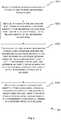
- Fig. 1shows an exemplary scenario of spectrum reuse.
- Two networks, a network 110 and a network 120are shown in Fig. 1 .
- the coverage area of the network 110 and the coverage area of the network 120partially overlap each other, as shown by the dashed lines in Fig. 1 .
- the networks 110 and 120may belong to different network operators and may be allocated with the same spectrum.
- the network 110includes two ANs, AN 111 and AN 112, and the network 120 includes two ANs, AN121 and AN 122. All the ANs 111, 112, 121 and 122 in Fig. 1 share the same spectrum.
- Fig. 1also shows three User Equipments (UEs) 101, 102 and 103.
- UEsUser Equipments
- the UE 101is served by the AN 111
- the UE 102is served by the AN 112
- the UE 103is served by the AN 122.
- the UE 102is located in the overlapped area and it is assumed here that the UE 102 is within the coverage of each of the ANs 111, 112 and 121.
- operations performed by the UE 102will be described as an example, without loss of generality.
- the UE 102may need to obtain information related to a neighboring AN (if any), e.g., to discover a neighboring AN or to perform measurements related to a neighboring AN. Such neighbor discovery or measurement can be periodical or event-triggered.
- the UE 102may need to measure a Reference Signal Received Power (RSRP) from an intra-network AN (i.e., an AN of its serving network 110), if any. In doing so, it first needs to listen to a beacon channel to detect if there is any beacon broadcast by a neighboring AN.
- RSRPReference Signal Received Power
- a beacon broadcast by a particular ANcontains a sync signal sequence (such as Primary Synchronization Signal (PSS) or Secondary Synchronization Signal (SSS) in Long Term Evolution (LTE) system), a reference signal (RS) sequence and system information.
- the system informationincludes a Network Identity (NI) which globally uniquely identifies the network the AN belongs to.
- a "network”can be a Public Land Mobile Network (PLMN) (in this case the NI can be a PLMN ID) and different "networks" are typically managed by different network operators.
- PLMNPublic Land Mobile Network
- the system informationfurther includes an AN Identity (Al) which uniquely identifies the AN locally within the network it belongs to.
- An example of the Alis the evolved NodeB (eNB) ID in LTE.
- the system informationfurther includes a Physical AN Identity (PANI) associated with physical layer functions of the AN.
- PANIPhysical AN Identity
- a PANIis uniquely associated with a combination of sync signal sequence and reference signal sequence (and their time and frequency locations) and such association is common among different networks.
- An example of the PANIis the Physical Cell ID (PCI) in LTE.
- the UE 102If there is a beacon broadcast by the AN 121 on the beacon channel, the UE 102 first detects the sync signal sequence blindly. When the UE 102 successfully detects the sync signal sequence, it knows the PANI from the detected sync signal sequence and thus determines the reference signal sequence in the beacon based on the PANI. At that time, the UE 102 measures the received power of the reference signal sequence as the RSRP. Then, the UE 102 derives a channel estimation based on the determined reference signal sequence, and finally decodes the system information in the beacon based on the channel estimation.
- the UE 102From the NI included in the system information, the UE 102 knows that the beacon is broadcast by the AN 121 which is an inter-network AN (i.e., an AN of a network different from its serving network 110) instead of an intra-network AN. Thus, the measured RSRP from the AN 121 will be discarded, without being reported to the AN 112.
- the AN 121is an inter-network AN (i.e., an AN of a network different from its serving network 110) instead of an intra-network AN.
- the UE 102if there is a beacon broadcast by the AN 111 on the beacon channel, the UE 102 also needs to detect the sync signal sequence blindly, determine the reference signal sequence, measure the RSRP and decode the system information. From the NI included in the system information, the UE 102 knows that the beacon is broadcast by the AN 111 which is an intra-network AN. Then, the measured RSRP from the AN 111 will be reported to the AN 112.
- the UEcannot identify whether a beacon it detects originates from an intra-network AN or an inter-network AN until it successfully decodes the system information.
- the RSRP from the inter-network ANis also measured, which is unnecessary and inefficient. This causes a certain amount of delay in the measurement-report process, which may be intolerable in some circumstances.
- the UEin order to support UE mobility in LTE, the UE is required in an event-triggered measurement to send a measurement report within a short period (e.g., 200 ms for intra-frequency non-DRX (Discontinuous Reception) scenario). The UE may fail to meet this requirement due to the delay.
- the UE 102may fail to decode the system information.
- PANIsThere are typically a limited number of PANIs available (i.e., 504 PCIs in LTE) and thus different ANs in the same or different network(s) may have the same PANI.
- PANIstypically a limited number of PANIs available (i.e., 504 PCIs in LTE) and thus different ANs in the same or different network(s) may have the same PANI.
- neighboring ANs of the same networkcan be allocated with different PANIs by the network operator.
- neighboring ANs from different networkse.g., AN 111 and AN 121) may have the same PANI due to lack of inter-operator coordination.
- the UE 102when the UE 102 receives two beacons simultaneously, one from the AN 111 and the other from the AN 121 (it is assumed here that the AN 111 and the AN 121 are synchronized and thus the beacons are aligned with each other), the beacons from the AN 111 and the AN 121 contain the same sync signal sequence and the same reference signal sequence.
- the UE 102cannot realize that it is receiving beacons from different ANs. Hence, it will successfully detect the sync signal sequence and accordingly measure a combined RSRP (which is meaningless) and derive a combined channel estimation of a channel between the UE 102 and the AN 111 and a channel between the UE 102 and the AN 121. With such combined channel estimation, the UE 102 cannot decode the system information in either of the beacons. In this case, it is impossible for the UE 102 to perform intra-network or inter-network measurement.
- US 2010/020710is directed to a method of facilitating PCI assignment.
- Vodafone's "Country Border Issue in EUTRAN", 3GPP draft, April 2008addresses the problem of PCI planning in country border areas.
- US 2010/0074235discloses a method of grouping cells for neighbour information distribution.
- a method for facilitating network identificationis provided according to Claim 1.
- a method for facilitating network identificationis provided an access node according to Claim 5. Details of embodiments are provided in the dependent claims.
- a method for facilitating network identificationcomprises, at an access node of a first network: detecting a physical-layer-related identity of each of one or more neighboring access nodes; and decoding, for each of the one or more neighboring access nodes, a network identity of the neighboring access node based on the detected physical-layer-related identity of the neighboring access node.
- the methodfurther comprises, for each of the one or more neighboring access nodes: determining whether the neighboring access node belongs to the first network or a different network based on the decoded network identity of the neighboring access node; and determining an identity group in which the detected physical-layer-related identity of the neighboring access node is included.
- the methodfurther comprises: selecting, as a physical-layer-related identity of the access node, a physical-layer-related identity from an identity group other than any identity group in which a physical-layer-related identity of a neighboring access node belonging to a different network is included.
- the physical-layer-related identity of the access nodeis selected from an identity group in which a physical-layer-related identity of a neighboring access node belonging to the first network is included.
- the methodfurther comprises: transmitting, to a User Equipment (UE), information indicating one or more identity groups associated with the first network.
- Each identity groupincludes at least the physical-layer-related identity of the access node or a physical-layer-related identity of at least one neighboring access node of the first network.
- UEUser Equipment
- each access nodeits physical-layer-related identity is at least associated with a synchronization signal sequence used by that access node.
- an access node of a first networkcomprises: a detecting unit configured to detect a physical-layer-related identity of each of one or more neighboring access nodes; a decoding unit configured to decode, for each of the one or more neighboring access nodes, a network identity of the neighboring access node based on the detected physical-layer-related identity of the neighboring access node; a determining unit configured to, for each of the one or more neighboring access nodes: determine whether the neighboring access node belongs to the first network or a different network based on the decoded network identity of the neighboring access node; and determine an identity group in which the detected physical-layer-related identity of the neighboring access node is included; and a selecting unit configured to select, as a physical-layer-related identity of the access node, a physical-layer-related identity from an identity group other than any identity group in which a physical-layer-related identity of a neighboring access node belonging to a different network is included.
- available physical-layer-related identitiesare divided into a number of identity groups and such division is known to access nodes and UEs.
- An access nodeselects, as its physical-layer-related identity, a physical-layer-related identity from an identity group other than any identity group in which a physical-layer-related identity of a neighboring access node belonging to a different network is included.
- the access node and its neighboring access nodes of the first networkare associated with one or more identity groups that are different from any identity group associated with any neighboring access node of any other network.
- a UEcan determine whether an access node it detects belongs to its serving network or not based on the identity group in which the physical-layer-related identity of that access node is included. In this way, it is possible to identify an intra-network access node or an inter-network access node in a quicker and more efficient manner, without having to decode its network identity.
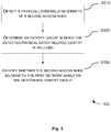
- Fig. 2is a flowchart illustrating a method 200 for facilitating network identification according to an embodiment of the present disclosure.
- the method 200can be performed at an access node of a first network (e.g., at AN 112 of the network 110 in Fig. 1 ).
- the access nodecan be an evolved NodeB (eNB) in an LTE network.
- eNBevolved NodeB
- the method 200includes the following steps.
- step S210a physical-layer-related identity of each of one or more neighboring access nodes is detected.
- a physical-layer-related identityis at least associated with a sync signal sequence used by that access node.
- a physical-layer-related identitycan be a PANI as mentioned above.
- a "neighboring" access node of a particular access nodehas a coverage area that at least partially overlaps the coverage area of the particular access node.
- the detection in the step S210is made by listening to a beacon channel and blindly detecting a sync signal sequence in a beacon broadcast by each neighboring access node on the beacon channel.
- the access nodeacts like a UE for AN discovery.
- a network identity of the neighboring access nodeis decoded based on the detected physical-layer-related identity of the neighboring access node.
- the network identitycan be an NI as mentioned above and can be decoded in the same way as described above in connection with NI.
- step S230for each of the one or more neighboring access nodes, it is first determined whether the neighboring access node belongs to the first network (e.g., the network 110 in Fig. 1 ) or a different network (e.g., the network 120 in Fig. 1 ) based on the decoded network identity of the neighboring access node.
- the first networke.g., the network 110 in Fig. 1
- a different networke.g., the network 120 in Fig. 1
- an identity group in which the detected physical-layer-related identity of the neighboring access node is includedis determined.
- available physical-layer-related identitiese.g., the entire PANI pool or a subset thereof
- identity groupsare divided into a number of identity groups and such division is known to all access nodes and UEs. This determination can be made based on such knowledge.
- a physical-layer-related identityis selected from an identity group other than any identity group in which a physical-layer-related identity of a neighboring access node belonging to a different network is included, as a physical-layer-related identity of the access node. This ensures that any two neighboring access nodes belonging to different networks will never have their physical-layer-related identities selected from the same identity group.
- the physical-layer-related identity of the access nodeis selected from an identity group in which a physical-layer-related identity of a neighboring access node belonging to the first network is included. That is, it is preferred that two or more neighboring access nodes of the same network will have their physical-layer-related identities selected from the same identity group. In this way, the number of identity groups used by neighboring access nodes of a single network can be reduced.
- the method 200further includes a step of transmitting, to a User Equipment (UE), information indicating one or more identity groups associated with the first network.
- UEUser Equipment
- Each of the one or more identity groupsincludes the physical-layer-related identity of the access node and/or a physical-layer-related identity of at least one neighboring access node of the first network. This is not necessary if the access node and its neighboring access nodes of the first network have their physical-layer-related identities selected from the same identity group.
- the access node and its neighboring access nodes of the first networkhave their physical-layer-related identities selected from more than one identity group, since it allows the UE to quickly identify an intra-network access node having a physical-layer-related identity selected from a different identity group than its serving access node.
- Fig. 3is a flowchart illustrating a method 300 for network identification according to an embodiment of the present disclosure.
- the method 300can be performed at a User Equipment (UE) served by a first access node of a first network (e.g., at UE 102 served by the AN 112 of the network 110 in Fig. 1 ).
- UEUser Equipment
- the method 300includes the following steps.
- a physical-layer-related identity of a second access nodeis detected.
- its physical-layer-related identityis at least associated with a sync signal sequence used by that access node.
- the detection in the step S310can be made by listening to a beacon channel and blindly detecting a sync signal sequence in a beacon broadcast by the second access node on the beacon channel.
- an identity group in which the detected physical-layer-related identity is includedis determined. As described above in connection with the step S230 in Fig. 2 , available physical-layer-related identities are divided into a number of identity groups and such division is known to all access nodes and UEs. This determination can be made based on such knowledge.
- step S330it is identified whether the second access node belongs to the first network based on the determined identity group.
- the first access node and its neighboring access nodes of the first networkare associated with one or more identity groups that are different from any identity group associated with any neighboring access node of any other network.
- the identifying step S330is performed by determining whether the determined identity group is identical to any of the one or more identity groups.
- the method 300further includes a step of receiving, from the first access node, information indicating the two or more identity groups.
- the identifying in the step S330facilitates measurement by the UE regarding the second access node.
- the second access nodebelongs to the first network and the UE needs to measure an RSRP from an intra-network access node (i.e., an access node of the first network), if any.
- the UEcan determine that the second access node belongs to the first network simply because the physical-layer-related identity of the second access node is included in an identity group associated with the first access node or any of its neighboring access nodes. Then, the UE can measure the RSRP and report the RSRP measurement to the first access node when appropriate, without having to decode the network identity of the second access node.
- the UEcan also avoid unnecessary measurement of RSRP from any inter-network access node. In this way, the delay in the measurement-report process can be reduced.
- the UElistens to the beacon channel, trying to discover any intra-network or inter-network neighboring access node, it can quickly determine whether a beacon is transmitted from an intra-network or inter-network neighboring access node with the above method 300.
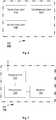
- FIG. 4is a block diagram of an access node 400 according to an embodiment of the present disclosure.
- the access node 400is e.g., an eNB of a first network.
- the access node 400includes a detecting unit 410 configured to detect a physical-layer-related identity of each of one or more neighboring access nodes.
- the access node 400further includes a decoding unit 420 configured to decode, for each of the one or more neighboring access nodes, a network identity of the neighboring access node based on the detected physical-layer-related identity of the neighboring access node.
- the access node 400further includes a determining unit 430 configured to, for each of the one or more neighboring access nodes: determine whether the neighboring access node belongs to the first network or a different network based on the decoded network identity of the neighboring access node; and determine an identity group in which the detected physical-layer-related identity of the neighboring access node is included.
- the access node 400further includes a selecting unit 440 configured to select, as a physical-layer-related identity of the access node, a physical-layer-related identity from an identity group other than any identity group in which a physical-layer-related identity of a neighboring access node belonging to a different network is included.
- the physical-layer-related identity of the access nodeis selected from an identity group in which a physical-layer-related identity of a neighboring access node belonging to the first network is included.
- the access node 400further includes a transmitting unit (not shown) configured to transmit, to a User Equipment (UE), information indicating one or more identity groups associated with the first network.
- UEUser Equipment
- Each identity groupincludes the physical-layer-related identity of the access node and/or a physical-layer-related identity of at least one neighboring access node of the first network.
- each access nodeits physical-layer-related identity is at least associated with a sync signal sequence used by that access node.
- Each of the units 410-440can be implemented as a pure hardware solution or as a combination of software and hardware, e.g., by one or more of: a processor or a micro processor and adequate software and memory for storing of the software, a Programmable Logic Device (PLD) or other electronic component(s) or processing circuitry configured to perform the actions described above, and illustrated, e.g., in Fig. 2 .
- PLDProgrammable Logic Device
- Fig. 5is a block diagram of an access node 500 according to another embodiment of the present disclosure.
- the access node 500is e.g., an eNB of a first network.
- the access node 500includes a transceiver 510, a processor 520 and a memory 530.
- the memory 530contains instructions executable by the processor 520 whereby the access node 500 is operative to: detect a physical-layer-related identity of each of one or more neighboring access nodes; and decode, for each of the one or more neighboring access nodes, a network identity of the neighboring access node based on the detected physical-layer-related identity of the neighboring access node.
- the memory 530further contains instructions executable by the processor 520 whereby the access node 500 is operative to: for each of the one or more neighboring access nodes: determine whether the neighboring access node belongs to the first network or a different network based on the decoded network identity of the neighboring access node; and determine an identity group in which the detected physical-layer-related identity of the neighboring access node is included.
- the memory 530contains instructions executable by the processor 520 whereby the access node 500 is operative to: select, as a physical-layer-related identity of the access node, a physical-layer-related identity from an identity group other than any identity group in which a physical-layer-related identity of a neighboring access node belonging to a different network is included.
- a UEis provided.
- Fig. 6is a block diagram of a UE 600 according to an embodiment of the present disclosure.
- the UE 600is served by a first access node of a first network.
- the UE 600includes a detecting unit 610 configured to detect a physical-layer-related identity of a second access node.
- the UE 600further includes a determining unit 620 configured to determine an identity group in which the detected physical-layer-related identity is included.
- the UE 600further includes an identifying unit 630 configured to identify whether the second access node belongs to the first network based on the determined identity group.
- the first access node and its neighboring access nodes of the first networkare associated with one or more identity groups that are different from any identity group associated with any neighboring access node of any other network.
- the identifying unit 630is configured to identify whether the second access node belongs to the first network by determining whether the determined identity group is identical to any of the one or more identity groups.
- the first access node and its neighboring access nodes of the first networkare associated with two or more identity groups.
- the UE 600further includes: a receiving unit (not shown) configured to receive, from the first access node, information indicating the two or more identity groups.
- each access nodeits physical-layer-related identity is at least associated with a sync signal sequence used by that access node.
- the identifying by the identifying unit 630facilitates measurement by the UE 600 regarding the second access node.
- Each of the units 610-630can be implemented as a pure hardware solution or as a combination of software and hardware, e.g., by one or more of: a processor or a micro processor and adequate software and memory for storing of the software, a Programmable Logic Device (PLD) or other electronic component(s) or processing circuitry configured to perform the actions described above, and illustrated, e.g., in Fig. 3 .
- PLDProgrammable Logic Device
- Fig. 7is a block diagram of a UE 700 according to another embodiment of the present disclosure.
- the UE 700is served by a first access node of a first network.
- the UE 700includes a transceiver 710, a processor 720 and a memory 730.
- the memory 730contains instructions executable by the processor 720 whereby the UE 700 is operative to: detect a physical-layer-related identity of a second access node; determine an identity group in which the detected physical-layer-related identity is included; and identify whether the second access node belongs to the first network based on the determined identity group.
- the first access node and its neighboring access nodes of the first networkare associated with one or more identity groups that are different from any identity group associated with any neighboring access node of any other network.
- the present disclosurealso provides at least one computer program product in the form of a non-volatile or volatile memory, e.g., an Electrically Erasable Programmable Read-Only Memory (EEPROM), a flash memory and a hard drive.
- the computer program productincludes a computer program.
- the computer programincludes: code/computer readable instructions, which when executed by the processor 520 causes the access node 500 to perform the actions, e.g., of the procedure described earlier in conjunction with Fig. 2 ; or code/computer readable instructions, which when executed by the processor 720 causes the UE 700 to perform the actions, e.g., of the procedure described earlier in conjunction with Fig. 3 .
- the computer program productmay be configured as a computer program code structured in computer program modules.
- the computer program modulescould essentially perform the actions of the flow illustrated in Fig. 2 , or the actions of the flow illustrated in Fig. 3 .
- the processormay be a single CPU (Central processing unit), but could also comprise two or more processing units.
- the processormay include general purpose microprocessors; instruction set processors and/or related chips sets and/or special purpose microprocessors such as Application Specific Integrated Circuit (ASICs).
- ASICsApplication Specific Integrated Circuit
- the processormay also comprise board memory for caching purposes.
- the computer programmay be carried by a computer program product connected to the processor.
- the computer program productmay comprise a computer readable medium on which the computer program is stored.
- the computer program productmay be a flash memory, a Random-access memory (RAM), a Read-Only Memory (ROM), or an EEPROM, and the computer program modules described above could in alternative embodiments be distributed on different computer program products in the form of memories.
Landscapes
- Engineering & Computer Science (AREA)
- Computer Networks & Wireless Communication (AREA)
- Signal Processing (AREA)
- Computer Security & Cryptography (AREA)
- Mobile Radio Communication Systems (AREA)
Description
- The present disclosure relates to wireless communications, and more particularly, to a method for facilitating network identification, an access node, a method for network identification and a User Equipment (UE).
- In order to provide large bandwidth and high-capacity coverage, Access Nodes (ANs) in a network typically share the entire spectrum available in the network. For example, in a millimeter wave (mmW) network, a number of "high-capacity coverage islands" are deployed and the entire spectrum available in the mmW network is reused by each of these islands.
Fig. 1 shows an exemplary scenario of spectrum reuse. Two networks, anetwork 110 and anetwork 120, are shown inFig. 1 . The coverage area of thenetwork 110 and the coverage area of thenetwork 120 partially overlap each other, as shown by the dashed lines inFig. 1 . Thenetworks network 110 includes two ANs, AN 111 and AN 112, and thenetwork 120 includes two ANs, AN121 andAN 122. All theANs Fig. 1 share the same spectrum.Fig. 1 also shows three User Equipments (UEs) 101, 102 and 103. Here, the UE 101 is served by the AN 111, the UE 102 is served by the AN 112 and the UE 103 is served by the AN 122. It can also be seen fromFig. 1 that the UE 102 is located in the overlapped area and it is assumed here that the UE 102 is within the coverage of each of the ANs 111, 112 and 121. In the following, operations performed by the UE 102 will be described as an example, without loss of generality. The UE 102 may need to obtain information related to a neighboring AN (if any), e.g., to discover a neighboring AN or to perform measurements related to a neighboring AN. Such neighbor discovery or measurement can be periodical or event-triggered. For example, the UE 102 may need to measure a Reference Signal Received Power (RSRP) from an intra-network AN (i.e., an AN of its serving network 110), if any. In doing so, it first needs to listen to a beacon channel to detect if there is any beacon broadcast by a neighboring AN.- A beacon broadcast by a particular AN contains a sync signal sequence (such as Primary Synchronization Signal (PSS) or Secondary Synchronization Signal (SSS) in Long Term Evolution (LTE) system), a reference signal (RS) sequence and system information. The system information includes a Network Identity (NI) which globally uniquely identifies the network the AN belongs to. In this context, a "network" can be a Public Land Mobile Network (PLMN) (in this case the NI can be a PLMN ID) and different "networks" are typically managed by different network operators. The system information further includes an AN Identity (Al) which uniquely identifies the AN locally within the network it belongs to. An example of the Al is the evolved NodeB (eNB) ID in LTE. The system information further includes a Physical AN Identity (PANI) associated with physical layer functions of the AN. A PANI is uniquely associated with a combination of sync signal sequence and reference signal sequence (and their time and frequency locations) and such association is common among different networks. An example of the PANI is the Physical Cell ID (PCI) in LTE.
- If there is a beacon broadcast by the
AN 121 on the beacon channel, the UE 102 first detects the sync signal sequence blindly. When theUE 102 successfully detects the sync signal sequence, it knows the PANI from the detected sync signal sequence and thus determines the reference signal sequence in the beacon based on the PANI. At that time, the UE 102 measures the received power of the reference signal sequence as the RSRP. Then, the UE 102 derives a channel estimation based on the determined reference signal sequence, and finally decodes the system information in the beacon based on the channel estimation. From the NI included in the system information, the UE 102 knows that the beacon is broadcast by theAN 121 which is an inter-network AN (i.e., an AN of a network different from its serving network 110) instead of an intra-network AN. Thus, the measured RSRP from theAN 121 will be discarded, without being reported to theAN 112. - Similarly, if there is a beacon broadcast by the
AN 111 on the beacon channel, the UE 102 also needs to detect the sync signal sequence blindly, determine the reference signal sequence, measure the RSRP and decode the system information. From the NI included in the system information, the UE 102 knows that the beacon is broadcast by theAN 111 which is an intra-network AN. Then, the measured RSRP from theAN 111 will be reported to theAN 112. - That is, the UE cannot identify whether a beacon it detects originates from an intra-network AN or an inter-network AN until it successfully decodes the system information. In the intra-network measurement as discussed above, the RSRP from the inter-network AN is also measured, which is unnecessary and inefficient. This causes a certain amount of delay in the measurement-report process, which may be intolerable in some circumstances. For example, in order to support UE mobility in LTE, the UE is required in an event-triggered measurement to send a measurement report within a short period (e.g., 200 ms for intra-frequency non-DRX (Discontinuous Reception) scenario). The UE may fail to meet this requirement due to the delay. Even worse, there is a case where the UE 102 may fail to decode the system information. There are typically a limited number of PANIs available (i.e., 504 PCIs in LTE) and thus different ANs in the same or different network(s) may have the same PANI. With cell planning, neighboring ANs of the same network can be allocated with different PANIs by the network operator. However, neighboring ANs from different networks (e.g.,
AN 111 and AN 121) may have the same PANI due to lack of inter-operator coordination. In this case, when the UE 102 receives two beacons simultaneously, one from theAN 111 and the other from the AN 121 (it is assumed here that theAN 111 and theAN 121 are synchronized and thus the beacons are aligned with each other), the beacons from theAN 111 and theAN 121 contain the same sync signal sequence and the same reference signal sequence. The UE 102 cannot realize that it is receiving beacons from different ANs. Hence, it will successfully detect the sync signal sequence and accordingly measure a combined RSRP (which is meaningless) and derive a combined channel estimation of a channel between the UE 102 and the AN 111 and a channel between the UE 102 and the AN 121. With such combined channel estimation, the UE 102 cannot decode the system information in either of the beacons. In this case, it is impossible for the UE 102 to perform intra-network or inter-network measurement. - There is thus a need for an improved solution for identifying an intra-network AN or an inter-network AN.
US 2010/020710 is directed to a method of facilitating PCI assignment.Vodafone's "Country Border Issue in EUTRAN", 3GPP draft, April 2008, addresses the problem of PCI planning in country border areas.US 2010/0074235 discloses a method of grouping cells for neighbour information distribution. - It is an object of the present disclosure to provide a method for facilitating network identification, at an access node, in a quicker and more efficient manner. In a first aspect, a method for facilitating network identification is provided according to Claim 1. In a second aspect, a method for facilitating network identification is provided an access node according to Claim 5. Details of embodiments are provided in the dependent claims.
- In a first aspect, a method for facilitating network identification is provided. The method comprises, at an access node of a first network: detecting a physical-layer-related identity of each of one or more neighboring access nodes; and decoding, for each of the one or more neighboring access nodes, a network identity of the neighboring access node based on the detected physical-layer-related identity of the neighboring access node. The method further comprises, for each of the one or more neighboring access nodes: determining whether the neighboring access node belongs to the first network or a different network based on the decoded network identity of the neighboring access node; and determining an identity group in which the detected physical-layer-related identity of the neighboring access node is included. The method further comprises: selecting, as a physical-layer-related identity of the access node, a physical-layer-related identity from an identity group other than any identity group in which a physical-layer-related identity of a neighboring access node belonging to a different network is included.
- In an embodiment, the physical-layer-related identity of the access node is selected from an identity group in which a physical-layer-related identity of a neighboring access node belonging to the first network is included.
- In an embodiment, the method further comprises: transmitting, to a User Equipment (UE), information indicating one or more identity groups associated with the first network. Each identity group includes at least the physical-layer-related identity of the access node or a physical-layer-related identity of at least one neighboring access node of the first network.
- In an embodiment, for each access node, its physical-layer-related identity is at least associated with a synchronization signal sequence used by that access node.
- In a second aspect, an access node of a first network is provided. The access node comprises: a detecting unit configured to detect a physical-layer-related identity of each of one or more neighboring access nodes; a decoding unit configured to decode, for each of the one or more neighboring access nodes, a network identity of the neighboring access node based on the detected physical-layer-related identity of the neighboring access node; a determining unit configured to, for each of the one or more neighboring access nodes: determine whether the neighboring access node belongs to the first network or a different network based on the decoded network identity of the neighboring access node; and determine an identity group in which the detected physical-layer-related identity of the neighboring access node is included; and a selecting unit configured to select, as a physical-layer-related identity of the access node, a physical-layer-related identity from an identity group other than any identity group in which a physical-layer-related identity of a neighboring access node belonging to a different network is included.
- The above embodiments of the first aspect are also applicable for the second aspect.
- With the embodiments of the present disclosure, available physical-layer-related identities are divided into a number of identity groups and such division is known to access nodes and UEs. An access node selects, as its physical-layer-related identity, a physical-layer-related identity from an identity group other than any identity group in which a physical-layer-related identity of a neighboring access node belonging to a different network is included. Hence, the access node and its neighboring access nodes of the first network, if any, are associated with one or more identity groups that are different from any identity group associated with any neighboring access node of any other network. Accordingly, a UE can determine whether an access node it detects belongs to its serving network or not based on the identity group in which the physical-layer-related identity of that access node is included. In this way, it is possible to identify an intra-network access node or an inter-network access node in a quicker and more efficient manner, without having to decode its network identity.
- The above and other objects, features and advantages will be more apparent from the following description of embodiments with reference to the figures, in which:
- Fig. 1
- is a schematic diagram showing an exemplary scenario of spectrum reuse;
- Fig. 2
- is a flowchart illustrating a method for facilitating network identification according to an embodiment of the present disclosure;
- Fig. 3
- is a flowchart illustrating a method for network identification according to an embodiment of the present disclosure;
- Fig. 4
- is a block diagram of an access node according to an embodiment of the present disclosure;
- Fig. 5
- is a block diagram of an access node according to another embodiment of the present disclosure;
- Fig. 6
- is a block diagram of a UE according to an embodiment of the present disclosure; and
- Fig. 7
- is a block diagram of a UE according to another embodiment of the present disclosure.
- The embodiments of the disclosure will be detailed below with reference to the drawings. It should be noted that the following embodiments are illustrative only, rather than limiting the scope of the disclosure.
Fig. 2 is a flowchart illustrating amethod 200 for facilitating network identification according to an embodiment of the present disclosure. Themethod 200 can be performed at an access node of a first network (e.g., at AN 112 of thenetwork 110 inFig. 1 ). For example, the access node can be an evolved NodeB (eNB) in an LTE network.- The
method 200 includes the following steps. - At step S210, a physical-layer-related identity of each of one or more neighboring access nodes is detected.
- Here, for each access node, its physical-layer-related identity is at least associated with a sync signal sequence used by that access node. For example, a physical-layer-related identity can be a PANI as mentioned above.
- In the context of the present disclosure, a "neighboring" access node of a particular access node has a coverage area that at least partially overlaps the coverage area of the particular access node. In an example, the detection in the step S210 is made by listening to a beacon channel and blindly detecting a sync signal sequence in a beacon broadcast by each neighboring access node on the beacon channel. In this case, the access node acts like a UE for AN discovery.
- At step S220, for each of the one or more neighboring access nodes, a network identity of the neighboring access node is decoded based on the detected physical-layer-related identity of the neighboring access node. Here, the network identity can be an NI as mentioned above and can be decoded in the same way as described above in connection with NI.
- At step S230, for each of the one or more neighboring access nodes, it is first determined whether the neighboring access node belongs to the first network (e.g., the
network 110 inFig. 1 ) or a different network (e.g., thenetwork 120 inFig. 1 ) based on the decoded network identity of the neighboring access node. - Then, an identity group in which the detected physical-layer-related identity of the neighboring access node is included is determined. Here, available physical-layer-related identities (e.g., the entire PANI pool or a subset thereof) are divided into a number of identity groups and such division is known to all access nodes and UEs. This determination can be made based on such knowledge.
- At step S240, a physical-layer-related identity is selected from an identity group other than any identity group in which a physical-layer-related identity of a neighboring access node belonging to a different network is included, as a physical-layer-related identity of the access node. This ensures that any two neighboring access nodes belonging to different networks will never have their physical-layer-related identities selected from the same identity group.
- Preferably, in the step S240, the physical-layer-related identity of the access node is selected from an identity group in which a physical-layer-related identity of a neighboring access node belonging to the first network is included. That is, it is preferred that two or more neighboring access nodes of the same network will have their physical-layer-related identities selected from the same identity group. In this way, the number of identity groups used by neighboring access nodes of a single network can be reduced.
- In an embodiment, the
method 200 further includes a step of transmitting, to a User Equipment (UE), information indicating one or more identity groups associated with the first network. Each of the one or more identity groups includes the physical-layer-related identity of the access node and/or a physical-layer-related identity of at least one neighboring access node of the first network. This is not necessary if the access node and its neighboring access nodes of the first network have their physical-layer-related identities selected from the same identity group. However, this is preferred when the access node and its neighboring access nodes of the first network have their physical-layer-related identities selected from more than one identity group, since it allows the UE to quickly identify an intra-network access node having a physical-layer-related identity selected from a different identity group than its serving access node. - Accordingly,
Fig. 3 is a flowchart illustrating amethod 300 for network identification according to an embodiment of the present disclosure. Themethod 300 can be performed at a User Equipment (UE) served by a first access node of a first network (e.g., atUE 102 served by theAN 112 of thenetwork 110 inFig. 1 ). - The
method 300 includes the following steps. - At step S310, a physical-layer-related identity of a second access node is detected. Here, for each access node, its physical-layer-related identity is at least associated with a sync signal sequence used by that access node. As described above, the detection in the step S310 can be made by listening to a beacon channel and blindly detecting a sync signal sequence in a beacon broadcast by the second access node on the beacon channel.
- At step S320, an identity group in which the detected physical-layer-related identity is included is determined. As described above in connection with the step S230 in
Fig. 2 , available physical-layer-related identities are divided into a number of identity groups and such division is known to all access nodes and UEs. This determination can be made based on such knowledge. - At step S330, it is identified whether the second access node belongs to the first network based on the determined identity group. Here, the first access node and its neighboring access nodes of the first network are associated with one or more identity groups that are different from any identity group associated with any neighboring access node of any other network.
- In an embodiment, the identifying step S330 is performed by determining whether the determined identity group is identical to any of the one or more identity groups.
- In an example where the first access node and its neighboring access nodes of the first network are associated with two or more identity groups, the
method 300 further includes a step of receiving, from the first access node, information indicating the two or more identity groups. - In an embodiment, the identifying in the step S330 facilitates measurement by the UE regarding the second access node. For example, it is assumed that the second access node belongs to the first network and the UE needs to measure an RSRP from an intra-network access node (i.e., an access node of the first network), if any. In this case, the UE can determine that the second access node belongs to the first network simply because the physical-layer-related identity of the second access node is included in an identity group associated with the first access node or any of its neighboring access nodes. Then, the UE can measure the RSRP and report the RSRP measurement to the first access node when appropriate, without having to decode the network identity of the second access node. In addition, the UE can also avoid unnecessary measurement of RSRP from any inter-network access node. In this way, the delay in the measurement-report process can be reduced.
- This also applies to neighbor discovery. When the UE listens to the beacon channel, trying to discover any intra-network or inter-network neighboring access node, it can quickly determine whether a beacon is transmitted from an intra-network or inter-network neighboring access node with the
above method 300. - Correspondingly to the
method 200 as described above, an access node is provided.Fig. 4 is a block diagram of anaccess node 400 according to an embodiment of the present disclosure. Theaccess node 400 is e.g., an eNB of a first network. - As shown in
Fig. 4 , theaccess node 400 includes a detectingunit 410 configured to detect a physical-layer-related identity of each of one or more neighboring access nodes. Theaccess node 400 further includes adecoding unit 420 configured to decode, for each of the one or more neighboring access nodes, a network identity of the neighboring access node based on the detected physical-layer-related identity of the neighboring access node. Theaccess node 400 further includes a determiningunit 430 configured to, for each of the one or more neighboring access nodes: determine whether the neighboring access node belongs to the first network or a different network based on the decoded network identity of the neighboring access node; and determine an identity group in which the detected physical-layer-related identity of the neighboring access node is included. Theaccess node 400 further includes a selectingunit 440 configured to select, as a physical-layer-related identity of the access node, a physical-layer-related identity from an identity group other than any identity group in which a physical-layer-related identity of a neighboring access node belonging to a different network is included. - In an embodiment, the physical-layer-related identity of the access node is selected from an identity group in which a physical-layer-related identity of a neighboring access node belonging to the first network is included.
- In an embodiment, the
access node 400 further includes a transmitting unit (not shown) configured to transmit, to a User Equipment (UE), information indicating one or more identity groups associated with the first network. Each identity group includes the physical-layer-related identity of the access node and/or a physical-layer-related identity of at least one neighboring access node of the first network. - In an embodiment, for each access node, its physical-layer-related identity is at least associated with a sync signal sequence used by that access node.
- Each of the units 410-440 can be implemented as a pure hardware solution or as a combination of software and hardware, e.g., by one or more of: a processor or a micro processor and adequate software and memory for storing of the software, a Programmable Logic Device (PLD) or other electronic component(s) or processing circuitry configured to perform the actions described above, and illustrated, e.g., in
Fig. 2 . Fig. 5 is a block diagram of anaccess node 500 according to another embodiment of the present disclosure. Theaccess node 500 is e.g., an eNB of a first network.- The
access node 500 includes atransceiver 510, aprocessor 520 and amemory 530. Thememory 530 contains instructions executable by theprocessor 520 whereby theaccess node 500 is operative to: detect a physical-layer-related identity of each of one or more neighboring access nodes; and decode, for each of the one or more neighboring access nodes, a network identity of the neighboring access node based on the detected physical-layer-related identity of the neighboring access node. Thememory 530 further contains instructions executable by theprocessor 520 whereby theaccess node 500 is operative to: for each of the one or more neighboring access nodes: determine whether the neighboring access node belongs to the first network or a different network based on the decoded network identity of the neighboring access node; and determine an identity group in which the detected physical-layer-related identity of the neighboring access node is included. Thememory 530 contains instructions executable by theprocessor 520 whereby theaccess node 500 is operative to: select, as a physical-layer-related identity of the access node, a physical-layer-related identity from an identity group other than any identity group in which a physical-layer-related identity of a neighboring access node belonging to a different network is included. - Correspondingly to the
method 300 as described above, a UE is provided.Fig. 6 is a block diagram of aUE 600 according to an embodiment of the present disclosure. TheUE 600 is served by a first access node of a first network. - As shown in
Fig. 6 , theUE 600 includes a detectingunit 610 configured to detect a physical-layer-related identity of a second access node. TheUE 600 further includes a determiningunit 620 configured to determine an identity group in which the detected physical-layer-related identity is included. TheUE 600 further includes an identifyingunit 630 configured to identify whether the second access node belongs to the first network based on the determined identity group. Here, the first access node and its neighboring access nodes of the first network are associated with one or more identity groups that are different from any identity group associated with any neighboring access node of any other network. - In an embodiment, the identifying
unit 630 is configured to identify whether the second access node belongs to the first network by determining whether the determined identity group is identical to any of the one or more identity groups. - In an embodiment, the first access node and its neighboring access nodes of the first network are associated with two or more identity groups. The
UE 600 further includes: a receiving unit (not shown) configured to receive, from the first access node, information indicating the two or more identity groups. - In an embodiment, for each access node, its physical-layer-related identity is at least associated with a sync signal sequence used by that access node.
- In an embodiment, the identifying by the identifying
unit 630 facilitates measurement by theUE 600 regarding the second access node. - Each of the units 610-630 can be implemented as a pure hardware solution or as a combination of software and hardware, e.g., by one or more of: a processor or a micro processor and adequate software and memory for storing of the software, a Programmable Logic Device (PLD) or other electronic component(s) or processing circuitry configured to perform the actions described above, and illustrated, e.g., in
Fig. 3 . Fig. 7 is a block diagram of a UE 700 according to another embodiment of the present disclosure. The UE 700 is served by a first access node of a first network.- The UE 700 includes a
transceiver 710, aprocessor 720 and amemory 730. Thememory 730 contains instructions executable by theprocessor 720 whereby the UE 700 is operative to: detect a physical-layer-related identity of a second access node; determine an identity group in which the detected physical-layer-related identity is included; and identify whether the second access node belongs to the first network based on the determined identity group. The first access node and its neighboring access nodes of the first network are associated with one or more identity groups that are different from any identity group associated with any neighboring access node of any other network. - The present disclosure also provides at least one computer program product in the form of a non-volatile or volatile memory, e.g., an Electrically Erasable Programmable Read-Only Memory (EEPROM), a flash memory and a hard drive. The computer program product includes a computer program. The computer program includes: code/computer readable instructions, which when executed by the
processor 520 causes theaccess node 500 to perform the actions, e.g., of the procedure described earlier in conjunction withFig. 2 ; or code/computer readable instructions, which when executed by theprocessor 720 causes the UE 700 to perform the actions, e.g., of the procedure described earlier in conjunction withFig. 3 . - The computer program product may be configured as a computer program code structured in computer program modules. The computer program modules could essentially perform the actions of the flow illustrated in
Fig. 2 , or the actions of the flow illustrated inFig. 3 . - The processor may be a single CPU (Central processing unit), but could also comprise two or more processing units. For example, the processor may include general purpose microprocessors; instruction set processors and/or related chips sets and/or special purpose microprocessors such as Application Specific Integrated Circuit (ASICs). The processor may also comprise board memory for caching purposes. The computer program may be carried by a computer program product connected to the processor. The computer program product may comprise a computer readable medium on which the computer program is stored. For example, the computer program product may be a flash memory, a Random-access memory (RAM), a Read-Only Memory (ROM), or an EEPROM, and the computer program modules described above could in alternative embodiments be distributed on different computer program products in the form of memories.
Claims (8)
- A method (200) for facilitating network identification, comprising, at an access node of a first network:- detecting (S210), by the access node, a physical-layer-related identity of each of one or more neighboring access nodes;- decoding (S220), by the access node, for each of the one or more neighboring access nodes, a network identity of the neighboring access node based on the detected physical-layer-related identity of the neighboring access node;- for each of the one or more neighboring access nodes:- determining (S230), by the access node, whether the neighboring access node belongs to the first network or a different network based on the decoded network identity of the neighboring access node; and- determining (S230), by the access node, an identity group in which the detected physical-layer-related identity of the neighboring access node is included, based on a knowledge of a repartition of physical-layer-related identities into groups that is known to all access nodes and UEs; and- selecting (S240), by the access node, as a physical-layer-related identity of the access node, a physical-layer-related identity from an identity group other than any identity group in which a physical-layer-related identity of a neighboring access node belonging to a different network is included.
- The method (200) of claim 1, wherein the physical-layer-related identity of the access node is selected from an identity group in which a physical-layer-related identity of a neighboring access node belonging to the first network is included.
- The method (200) of claim 1 or 2, further comprising:- transmitting, by the access node, to a User Equipment, UE, information indicating one or more identity groups associated with the first network, each identity group including at least the physical-layer-related identity of the access node or a physical-layer-related identity of at least one neighboring access node of the first network.
- The method (200) of any of claims 1-3, wherein, for each access node, its physical-layer-related identity is at least associated with a synchronization signal sequence used by that access node.
- An access node (400) of a first network, comprising:- a detecting unit (410) configured to detect a physical-layer-related identity of each of one or more neighboring access nodes;- a decoding unit (420) configured to decode, for each of the one or more neighboring access nodes, a network identity of the neighboring access node based on the detected physical-layer-related identity of the neighboring access node;- a determining unit (430) configured to, for each of the one or more neighboring access nodes:- determine whether the neighboring access node belongs to the first network or a different network based on the decoded network identity of the neighboring access node; and- determine an identity group in which the detected physical-layer-related identity of the neighboring access node is included, based on a knowledge of a repartition of physical-layer-related identities into groups that is known to all access nodes and UEs; and- a selecting unit (440) configured to select, as a physical-layer-related identity of the access node, a physical-layer-related identity from an identity group other than any identity group in which a physical-layer-related identity of a neighboring access node belonging to a different network is included.
- The access node (400) of claim 5, wherein the physical-layer-related identity of the access node is selected from an identity group in which a physical-layer-related identity of a neighboring access node belonging to the first network is included.
- The access node (400) of claim 5 or 6, further comprising:- a transmitting unit configured to transmit, to a User Equipment, UE, information indicating one or more identity groups associated with the first network, each identity group including at least the physical-layer-related identity of the access node or a physical-layer-related identity of at least one neighboring access node of the first network.
- The access node (400) of any of claims 5-7, wherein, for each access node, its physical-layer-related identity is at least associated with a synchronization signal sequence used by that access node.
Applications Claiming Priority (1)
| Application Number | Priority Date | Filing Date | Title |
|---|---|---|---|
| PCT/CN2014/093228WO2016090526A1 (en) | 2014-12-08 | 2014-12-08 | Method for facilitating network identification, access node, method for network identification and user equipment |
Publications (3)
| Publication Number | Publication Date |
|---|---|
| EP3231223A1 EP3231223A1 (en) | 2017-10-18 |
| EP3231223A4 EP3231223A4 (en) | 2018-06-20 |
| EP3231223B1true EP3231223B1 (en) | 2019-08-07 |
Family
ID=56106396
Family Applications (1)
| Application Number | Title | Priority Date | Filing Date |
|---|---|---|---|
| EP14907856.0ANot-in-forceEP3231223B1 (en) | 2014-12-08 | 2014-12-08 | Method for facilitating network identification, access node, method for network identification and user equipment |
Country Status (8)
| Country | Link |
|---|---|
| US (2) | US10299194B2 (en) |
| EP (1) | EP3231223B1 (en) |
| JP (1) | JP6445695B2 (en) |
| CN (1) | CN107005925B (en) |
| PH (1) | PH12017500804A1 (en) |
| RU (1) | RU2679720C2 (en) |
| WO (1) | WO2016090526A1 (en) |
| ZA (1) | ZA201702950B (en) |
Family Cites Families (24)
| Publication number | Priority date | Publication date | Assignee | Title |
|---|---|---|---|---|
| US7171203B2 (en)* | 2004-01-07 | 2007-01-30 | Research In Motion Limited | Apparatus, and associated method, for facilitating selection by a mobile node of a network through which to communicate |
| US9775096B2 (en)* | 2007-10-08 | 2017-09-26 | Qualcomm Incorporated | Access terminal configuration and access control |
| US8594060B2 (en)* | 2008-04-22 | 2013-11-26 | Nokia Corporation | Grouping of cells for efficient neighbor cell information distribution |
| EP2289269A2 (en) | 2008-06-18 | 2011-03-02 | Telefonaktiebolaget L M Ericsson (PUBL) | Method and arrangement in a communication network system |
| US8391158B2 (en)* | 2008-07-25 | 2013-03-05 | Qualcomm Incorporated | Cell identifier assignment and selection |
| JP2010041652A (en)* | 2008-08-08 | 2010-02-18 | Fujitsu Ltd | Terminal apparatus, base station apparatus detection method, wireless communication system, and base station apparatus |
| CN101651881A (en)* | 2008-08-13 | 2010-02-17 | 华为技术有限公司 | Method, system and equipment for sending identifier and realizing neighbor relation |
| CN102124786B (en)* | 2008-08-18 | 2014-06-18 | 艾利森电话股份有限公司 | A method of transmitting cell identity information |
| US8160590B2 (en)* | 2008-09-18 | 2012-04-17 | Infineon Technologies Ag | Method for determining the type of a mobile radio base station; radio communication terminal and network devices; radio communication smart card device |
| CN101888590B (en)* | 2009-05-11 | 2014-08-13 | 中兴通讯股份有限公司 | Paging method and system of terminal in multi-carrier system |
| WO2011023234A1 (en) | 2009-08-27 | 2011-03-03 | Nokia Siemens Networks Oy | Method and apparatus for operation of a communication network |
| US9294972B2 (en) | 2010-04-28 | 2016-03-22 | Qualcomm Incorporated | Neighbor relation information management |
| EP2569990B1 (en)* | 2010-05-11 | 2018-07-04 | Nokia Technologies Oy | Method and apparatus for identifying closed subscriber group cells |
| WO2012045345A1 (en)* | 2010-10-06 | 2012-04-12 | Nokia Siemens Networks Oy | Coordinating communications in radio service areas |
| US9113368B2 (en)* | 2011-03-25 | 2015-08-18 | Qualcomm Incorporated | Maintaining neighbor cell list |
| WO2012134138A2 (en)* | 2011-03-28 | 2012-10-04 | 엘지전자 주식회사 | Method for transmitting an uplink signal, method for receiving an uplink signal, user equipment, and base station |
| WO2012138274A1 (en)* | 2011-04-05 | 2012-10-11 | Telefonaktiebolaget L M Ericsson (Publ) | Autonomous maximum power setting based on channel fingerprint |
| WO2012150889A1 (en)* | 2011-05-03 | 2012-11-08 | Telefonaktiebolaget L M Ericsson (Publ) | Physical cell identifier (pci) adaptation to mitigate interference in heterogeneous cellular network |
| CN103004252B (en)* | 2011-06-16 | 2016-08-10 | 华为技术有限公司 | Method of sending and receiving and equipment |
| WO2013113361A1 (en)* | 2012-01-30 | 2013-08-08 | Fujitsu Limited | Synchronization signals in a wireless communication system |
| US9402256B2 (en)* | 2012-08-08 | 2016-07-26 | Blackberry Limited | Method and system having reference signal design for new carrier types |
| CN103181203B (en)* | 2012-09-11 | 2016-11-09 | 华为技术有限公司 | Method and device for obtaining neighbor cell information |
| US9055390B2 (en)* | 2012-10-19 | 2015-06-09 | Hong Kong Applied Science And Technology Research Institute Co., Ltd. | Apparatus, system, and method for peer group formation for mobile devices by proximity sensing |
| EP3751910A1 (en)* | 2013-11-21 | 2020-12-16 | Huawei Technologies Co., Ltd. | Systems and methods for non-cellular wireless access |
- 2014
- 2014-12-08EPEP14907856.0Apatent/EP3231223B1/ennot_activeNot-in-force
- 2014-12-08WOPCT/CN2014/093228patent/WO2016090526A1/enactiveApplication Filing
- 2014-12-08JPJP2017524439Apatent/JP6445695B2/enactiveActive
- 2014-12-08CNCN201480083878.4Apatent/CN107005925B/ennot_activeExpired - Fee Related
- 2014-12-08USUS15/527,802patent/US10299194B2/enactiveActive
- 2014-12-08RURU2017123941Apatent/RU2679720C2/ennot_activeIP Right Cessation
- 2017
- 2017-04-26ZAZA2017/02950Apatent/ZA201702950B/enunknown
- 2017-05-02PHPH12017500804Apatent/PH12017500804A1/enunknown
- 2019
- 2019-04-05USUS16/377,135patent/US11071046B2/ennot_activeExpired - Fee Related
Non-Patent Citations (1)
| Title |
|---|
| None* |
Also Published As
| Publication number | Publication date |
|---|---|
| RU2017123941A (en) | 2019-01-10 |
| EP3231223A1 (en) | 2017-10-18 |
| RU2017123941A3 (en) | 2019-01-10 |
| EP3231223A4 (en) | 2018-06-20 |
| WO2016090526A1 (en) | 2016-06-16 |
| CN107005925B (en) | 2020-07-17 |
| JP2017538339A (en) | 2017-12-21 |
| US20190239148A1 (en) | 2019-08-01 |
| CN107005925A (en) | 2017-08-01 |
| US20180352502A1 (en) | 2018-12-06 |
| US10299194B2 (en) | 2019-05-21 |
| ZA201702950B (en) | 2018-08-29 |
| PH12017500804A1 (en) | 2017-10-02 |
| US11071046B2 (en) | 2021-07-20 |
| JP6445695B2 (en) | 2018-12-26 |
| RU2679720C2 (en) | 2019-02-12 |
Similar Documents
| Publication | Publication Date | Title |
|---|---|---|
| CN111727632B (en) | Cell information acquisition method and device | |
| US11496977B2 (en) | User apparatus, base station, discovery signal reception method and discovery signal transmission method | |
| EP2842367B1 (en) | Apparatus and method for cell information indication in a wireless network | |
| US10681582B2 (en) | Information transmission method, base station, user equipment, and storage medium | |
| US10517031B2 (en) | User apparatus, base station, cell selection control method, and parameter transmission method | |
| EP3311608B1 (en) | Method for neighbor cell measurement, base station and terminal device | |
| WO2019144399A1 (en) | Cell reselection method and device, and computer storage medium | |
| US11706588B2 (en) | Positioning method and apparatus for UE | |
| US10517023B2 (en) | Methods and arrangements for supporting mobility of a communication device in a wireless communication network | |
| WO2013060141A1 (en) | Method, apparatus and evolved node b(enb) for cell identification | |
| EP3154282B1 (en) | Small cell discovery method and system, base station, and user equipment | |
| US20200187138A1 (en) | Method, network apparatus, and terminal apparatus for indicating position of synchronization signal block | |
| EP3231223B1 (en) | Method for facilitating network identification, access node, method for network identification and user equipment | |
| EP3580957B1 (en) | Adaptive mobility reference signal configuration | |
| EP2911437B1 (en) | Cell measurement method, user equipment and base station | |
| EP3216286B1 (en) | Method and network node for coordination of beacon transmissions | |
| HK1234937A1 (en) | Method for facilitating network identification, access node, method for network identification and user equipment | |
| JP2015216471A (en) | Communication method, and communication system | |
| WO2017082784A1 (en) | Enabling communication in a communication network |
Legal Events
| Date | Code | Title | Description |
|---|---|---|---|
| STAA | Information on the status of an ep patent application or granted ep patent | Free format text:STATUS: THE INTERNATIONAL PUBLICATION HAS BEEN MADE | |
| PUAI | Public reference made under article 153(3) epc to a published international application that has entered the european phase | Free format text:ORIGINAL CODE: 0009012 | |
| STAA | Information on the status of an ep patent application or granted ep patent | Free format text:STATUS: REQUEST FOR EXAMINATION WAS MADE | |
| 17P | Request for examination filed | Effective date:20170524 | |
| AK | Designated contracting states | Kind code of ref document:A1 Designated state(s):AL AT BE BG CH CY CZ DE DK EE ES FI FR GB GR HR HU IE IS IT LI LT LU LV MC MK MT NL NO PL PT RO RS SE SI SK SM TR | |
| AX | Request for extension of the european patent | Extension state:BA ME | |
| DAX | Request for extension of the european patent (deleted) | ||
| A4 | Supplementary search report drawn up and despatched | Effective date:20180524 | |
| RIC1 | Information provided on ipc code assigned before grant | Ipc:H04W 48/16 20090101AFI20180517BHEP Ipc:H04W 88/08 20090101ALN20180517BHEP | |
| STAA | Information on the status of an ep patent application or granted ep patent | Free format text:STATUS: EXAMINATION IS IN PROGRESS | |
| 17Q | First examination report despatched | Effective date:20190220 | |
| GRAP | Despatch of communication of intention to grant a patent | Free format text:ORIGINAL CODE: EPIDOSNIGR1 | |
| STAA | Information on the status of an ep patent application or granted ep patent | Free format text:STATUS: GRANT OF PATENT IS INTENDED | |
| RIC1 | Information provided on ipc code assigned before grant | Ipc:H04W 48/16 20090101AFI20190425BHEP Ipc:H04W 88/08 20090101ALN20190425BHEP | |
| RIC1 | Information provided on ipc code assigned before grant | Ipc:H04W 88/08 20090101ALN20190507BHEP Ipc:H04W 48/16 20090101AFI20190507BHEP | |
| INTG | Intention to grant announced | Effective date:20190523 | |
| GRAS | Grant fee paid | Free format text:ORIGINAL CODE: EPIDOSNIGR3 | |
| GRAA | (expected) grant | Free format text:ORIGINAL CODE: 0009210 | |
| STAA | Information on the status of an ep patent application or granted ep patent | Free format text:STATUS: THE PATENT HAS BEEN GRANTED | |
| AK | Designated contracting states | Kind code of ref document:B1 Designated state(s):AL AT BE BG CH CY CZ DE DK EE ES FI FR GB GR HR HU IE IS IT LI LT LU LV MC MK MT NL NO PL PT RO RS SE SI SK SM TR | |
| REG | Reference to a national code | Ref country code:GB Ref legal event code:FG4D | |
| REG | Reference to a national code | Ref country code:CH Ref legal event code:EP Ref country code:AT Ref legal event code:REF Ref document number:1165790 Country of ref document:AT Kind code of ref document:T Effective date:20190815 | |
| REG | Reference to a national code | Ref country code:DE Ref legal event code:R096 Ref document number:602014051597 Country of ref document:DE | |
| REG | Reference to a national code | Ref country code:IE Ref legal event code:FG4D | |
| REG | Reference to a national code | Ref country code:NL Ref legal event code:MP Effective date:20190807 | |
| REG | Reference to a national code | Ref country code:LT Ref legal event code:MG4D | |
| PG25 | Lapsed in a contracting state [announced via postgrant information from national office to epo] | Ref country code:BG Free format text:LAPSE BECAUSE OF FAILURE TO SUBMIT A TRANSLATION OF THE DESCRIPTION OR TO PAY THE FEE WITHIN THE PRESCRIBED TIME-LIMIT Effective date:20191107 Ref country code:NL Free format text:LAPSE BECAUSE OF FAILURE TO SUBMIT A TRANSLATION OF THE DESCRIPTION OR TO PAY THE FEE WITHIN THE PRESCRIBED TIME-LIMIT Effective date:20190807 Ref country code:SE Free format text:LAPSE BECAUSE OF FAILURE TO SUBMIT A TRANSLATION OF THE DESCRIPTION OR TO PAY THE FEE WITHIN THE PRESCRIBED TIME-LIMIT Effective date:20190807 Ref country code:NO Free format text:LAPSE BECAUSE OF FAILURE TO SUBMIT A TRANSLATION OF THE DESCRIPTION OR TO PAY THE FEE WITHIN THE PRESCRIBED TIME-LIMIT Effective date:20191107 Ref country code:FI Free format text:LAPSE BECAUSE OF FAILURE TO SUBMIT A TRANSLATION OF THE DESCRIPTION OR TO PAY THE FEE WITHIN THE PRESCRIBED TIME-LIMIT Effective date:20190807 Ref country code:LT Free format text:LAPSE BECAUSE OF FAILURE TO SUBMIT A TRANSLATION OF THE DESCRIPTION OR TO PAY THE FEE WITHIN THE PRESCRIBED TIME-LIMIT Effective date:20190807 Ref country code:HR Free format text:LAPSE BECAUSE OF FAILURE TO SUBMIT A TRANSLATION OF THE DESCRIPTION OR TO PAY THE FEE WITHIN THE PRESCRIBED TIME-LIMIT Effective date:20190807 Ref country code:PT Free format text:LAPSE BECAUSE OF FAILURE TO SUBMIT A TRANSLATION OF THE DESCRIPTION OR TO PAY THE FEE WITHIN THE PRESCRIBED TIME-LIMIT Effective date:20191209 | |
| REG | Reference to a national code | Ref country code:AT Ref legal event code:MK05 Ref document number:1165790 Country of ref document:AT Kind code of ref document:T Effective date:20190807 | |
| PG25 | Lapsed in a contracting state [announced via postgrant information from national office to epo] | Ref country code:ES Free format text:LAPSE BECAUSE OF FAILURE TO SUBMIT A TRANSLATION OF THE DESCRIPTION OR TO PAY THE FEE WITHIN THE PRESCRIBED TIME-LIMIT Effective date:20190807 Ref country code:LV Free format text:LAPSE BECAUSE OF FAILURE TO SUBMIT A TRANSLATION OF THE DESCRIPTION OR TO PAY THE FEE WITHIN THE PRESCRIBED TIME-LIMIT Effective date:20190807 Ref country code:GR Free format text:LAPSE BECAUSE OF FAILURE TO SUBMIT A TRANSLATION OF THE DESCRIPTION OR TO PAY THE FEE WITHIN THE PRESCRIBED TIME-LIMIT Effective date:20191108 Ref country code:IS Free format text:LAPSE BECAUSE OF FAILURE TO SUBMIT A TRANSLATION OF THE DESCRIPTION OR TO PAY THE FEE WITHIN THE PRESCRIBED TIME-LIMIT Effective date:20191207 Ref country code:RS Free format text:LAPSE BECAUSE OF FAILURE TO SUBMIT A TRANSLATION OF THE DESCRIPTION OR TO PAY THE FEE WITHIN THE PRESCRIBED TIME-LIMIT Effective date:20190807 Ref country code:AL Free format text:LAPSE BECAUSE OF FAILURE TO SUBMIT A TRANSLATION OF THE DESCRIPTION OR TO PAY THE FEE WITHIN THE PRESCRIBED TIME-LIMIT Effective date:20190807 | |
| PG25 | Lapsed in a contracting state [announced via postgrant information from national office to epo] | Ref country code:TR Free format text:LAPSE BECAUSE OF FAILURE TO SUBMIT A TRANSLATION OF THE DESCRIPTION OR TO PAY THE FEE WITHIN THE PRESCRIBED TIME-LIMIT Effective date:20190807 | |
| PG25 | Lapsed in a contracting state [announced via postgrant information from national office to epo] | Ref country code:PL Free format text:LAPSE BECAUSE OF FAILURE TO SUBMIT A TRANSLATION OF THE DESCRIPTION OR TO PAY THE FEE WITHIN THE PRESCRIBED TIME-LIMIT Effective date:20190807 Ref country code:DK Free format text:LAPSE BECAUSE OF FAILURE TO SUBMIT A TRANSLATION OF THE DESCRIPTION OR TO PAY THE FEE WITHIN THE PRESCRIBED TIME-LIMIT Effective date:20190807 Ref country code:RO Free format text:LAPSE BECAUSE OF FAILURE TO SUBMIT A TRANSLATION OF THE DESCRIPTION OR TO PAY THE FEE WITHIN THE PRESCRIBED TIME-LIMIT Effective date:20190807 Ref country code:IT Free format text:LAPSE BECAUSE OF FAILURE TO SUBMIT A TRANSLATION OF THE DESCRIPTION OR TO PAY THE FEE WITHIN THE PRESCRIBED TIME-LIMIT Effective date:20190807 Ref country code:AT Free format text:LAPSE BECAUSE OF FAILURE TO SUBMIT A TRANSLATION OF THE DESCRIPTION OR TO PAY THE FEE WITHIN THE PRESCRIBED TIME-LIMIT Effective date:20190807 Ref country code:EE Free format text:LAPSE BECAUSE OF FAILURE TO SUBMIT A TRANSLATION OF THE DESCRIPTION OR TO PAY THE FEE WITHIN THE PRESCRIBED TIME-LIMIT Effective date:20190807 | |
| PG25 | Lapsed in a contracting state [announced via postgrant information from national office to epo] | Ref country code:IS Free format text:LAPSE BECAUSE OF FAILURE TO SUBMIT A TRANSLATION OF THE DESCRIPTION OR TO PAY THE FEE WITHIN THE PRESCRIBED TIME-LIMIT Effective date:20200224 Ref country code:CZ Free format text:LAPSE BECAUSE OF FAILURE TO SUBMIT A TRANSLATION OF THE DESCRIPTION OR TO PAY THE FEE WITHIN THE PRESCRIBED TIME-LIMIT Effective date:20190807 Ref country code:SK Free format text:LAPSE BECAUSE OF FAILURE TO SUBMIT A TRANSLATION OF THE DESCRIPTION OR TO PAY THE FEE WITHIN THE PRESCRIBED TIME-LIMIT Effective date:20190807 Ref country code:SM Free format text:LAPSE BECAUSE OF FAILURE TO SUBMIT A TRANSLATION OF THE DESCRIPTION OR TO PAY THE FEE WITHIN THE PRESCRIBED TIME-LIMIT Effective date:20190807 | |
| REG | Reference to a national code | Ref country code:DE Ref legal event code:R097 Ref document number:602014051597 Country of ref document:DE | |
| PLBE | No opposition filed within time limit | Free format text:ORIGINAL CODE: 0009261 | |
| STAA | Information on the status of an ep patent application or granted ep patent | Free format text:STATUS: NO OPPOSITION FILED WITHIN TIME LIMIT | |
| PG2D | Information on lapse in contracting state deleted | Ref country code:IS | |
| REG | Reference to a national code | Ref country code:CH Ref legal event code:PL | |
| 26N | No opposition filed | Effective date:20200603 | |
| REG | Reference to a national code | Ref country code:BE Ref legal event code:MM Effective date:20191231 | |
| PG25 | Lapsed in a contracting state [announced via postgrant information from national office to epo] | Ref country code:MC Free format text:LAPSE BECAUSE OF FAILURE TO SUBMIT A TRANSLATION OF THE DESCRIPTION OR TO PAY THE FEE WITHIN THE PRESCRIBED TIME-LIMIT Effective date:20190807 Ref country code:SI Free format text:LAPSE BECAUSE OF FAILURE TO SUBMIT A TRANSLATION OF THE DESCRIPTION OR TO PAY THE FEE WITHIN THE PRESCRIBED TIME-LIMIT Effective date:20190807 | |
| PG25 | Lapsed in a contracting state [announced via postgrant information from national office to epo] | Ref country code:LU Free format text:LAPSE BECAUSE OF NON-PAYMENT OF DUE FEES Effective date:20191208 Ref country code:FR Free format text:LAPSE BECAUSE OF NON-PAYMENT OF DUE FEES Effective date:20191231 Ref country code:IE Free format text:LAPSE BECAUSE OF NON-PAYMENT OF DUE FEES Effective date:20191208 | |
| PG25 | Lapsed in a contracting state [announced via postgrant information from national office to epo] | Ref country code:BE Free format text:LAPSE BECAUSE OF NON-PAYMENT OF DUE FEES Effective date:20191231 Ref country code:LI Free format text:LAPSE BECAUSE OF NON-PAYMENT OF DUE FEES Effective date:20191231 Ref country code:CH Free format text:LAPSE BECAUSE OF NON-PAYMENT OF DUE FEES Effective date:20191231 | |
| PG25 | Lapsed in a contracting state [announced via postgrant information from national office to epo] | Ref country code:CY Free format text:LAPSE BECAUSE OF FAILURE TO SUBMIT A TRANSLATION OF THE DESCRIPTION OR TO PAY THE FEE WITHIN THE PRESCRIBED TIME-LIMIT Effective date:20190807 | |
| PG25 | Lapsed in a contracting state [announced via postgrant information from national office to epo] | Ref country code:HU Free format text:LAPSE BECAUSE OF FAILURE TO SUBMIT A TRANSLATION OF THE DESCRIPTION OR TO PAY THE FEE WITHIN THE PRESCRIBED TIME-LIMIT; INVALID AB INITIO Effective date:20141208 Ref country code:MT Free format text:LAPSE BECAUSE OF FAILURE TO SUBMIT A TRANSLATION OF THE DESCRIPTION OR TO PAY THE FEE WITHIN THE PRESCRIBED TIME-LIMIT Effective date:20190807 | |
| PG25 | Lapsed in a contracting state [announced via postgrant information from national office to epo] | Ref country code:MK Free format text:LAPSE BECAUSE OF FAILURE TO SUBMIT A TRANSLATION OF THE DESCRIPTION OR TO PAY THE FEE WITHIN THE PRESCRIBED TIME-LIMIT Effective date:20190807 | |
| PGFP | Annual fee paid to national office [announced via postgrant information from national office to epo] | Ref country code:GB Payment date:20221227 Year of fee payment:9 | |
| PGFP | Annual fee paid to national office [announced via postgrant information from national office to epo] | Ref country code:DE Payment date:20221228 Year of fee payment:9 | |
| REG | Reference to a national code | Ref country code:DE Ref legal event code:R119 Ref document number:602014051597 Country of ref document:DE | |
| GBPC | Gb: european patent ceased through non-payment of renewal fee | Effective date:20231208 | |
| PG25 | Lapsed in a contracting state [announced via postgrant information from national office to epo] | Ref country code:DE Free format text:LAPSE BECAUSE OF NON-PAYMENT OF DUE FEES Effective date:20240702 | |
| PG25 | Lapsed in a contracting state [announced via postgrant information from national office to epo] | Ref country code:GB Free format text:LAPSE BECAUSE OF NON-PAYMENT OF DUE FEES Effective date:20231208 | |
| PG25 | Lapsed in a contracting state [announced via postgrant information from national office to epo] | Ref country code:GB Free format text:LAPSE BECAUSE OF NON-PAYMENT OF DUE FEES Effective date:20231208 Ref country code:DE Free format text:LAPSE BECAUSE OF NON-PAYMENT OF DUE FEES Effective date:20240702 |