EP3230114B1 - Securing device and fastening device for securing vehicles - Google Patents
Securing device and fastening device for securing vehiclesDownload PDFInfo
- Publication number
- EP3230114B1 EP3230114B1EP14816203.5AEP14816203AEP3230114B1EP 3230114 B1EP3230114 B1EP 3230114B1EP 14816203 AEP14816203 AEP 14816203AEP 3230114 B1EP3230114 B1EP 3230114B1
- Authority
- EP
- European Patent Office
- Prior art keywords
- securing
- unit
- order
- connecting element
- designed
- Prior art date
- Legal status (The legal status is an assumption and is not a legal conclusion. Google has not performed a legal analysis and makes no representation as to the accuracy of the status listed.)
- Active
Links
Images


Classifications
- B—PERFORMING OPERATIONS; TRANSPORTING
- B62—LAND VEHICLES FOR TRAVELLING OTHERWISE THAN ON RAILS
- B62H—CYCLE STANDS; SUPPORTS OR HOLDERS FOR PARKING OR STORING CYCLES; APPLIANCES PREVENTING OR INDICATING UNAUTHORIZED USE OR THEFT OF CYCLES; LOCKS INTEGRAL WITH CYCLES; DEVICES FOR LEARNING TO RIDE CYCLES
- B62H5/00—Appliances preventing or indicating unauthorised use or theft of cycles; Locks integral with cycles
- B62H5/003—Appliances preventing or indicating unauthorised use or theft of cycles; Locks integral with cycles using chains or cables
- B—PERFORMING OPERATIONS; TRANSPORTING
- B60—VEHICLES IN GENERAL
- B60L—PROPULSION OF ELECTRICALLY-PROPELLED VEHICLES; SUPPLYING ELECTRIC POWER FOR AUXILIARY EQUIPMENT OF ELECTRICALLY-PROPELLED VEHICLES; ELECTRODYNAMIC BRAKE SYSTEMS FOR VEHICLES IN GENERAL; MAGNETIC SUSPENSION OR LEVITATION FOR VEHICLES; MONITORING OPERATING VARIABLES OF ELECTRICALLY-PROPELLED VEHICLES; ELECTRIC SAFETY DEVICES FOR ELECTRICALLY-PROPELLED VEHICLES
- B60L50/00—Electric propulsion with power supplied within the vehicle
- B60L50/20—Electric propulsion with power supplied within the vehicle using propulsion power generated by humans or animals
- B—PERFORMING OPERATIONS; TRANSPORTING
- B60—VEHICLES IN GENERAL
- B60L—PROPULSION OF ELECTRICALLY-PROPELLED VEHICLES; SUPPLYING ELECTRIC POWER FOR AUXILIARY EQUIPMENT OF ELECTRICALLY-PROPELLED VEHICLES; ELECTRODYNAMIC BRAKE SYSTEMS FOR VEHICLES IN GENERAL; MAGNETIC SUSPENSION OR LEVITATION FOR VEHICLES; MONITORING OPERATING VARIABLES OF ELECTRICALLY-PROPELLED VEHICLES; ELECTRIC SAFETY DEVICES FOR ELECTRICALLY-PROPELLED VEHICLES
- B60L53/00—Methods of charging batteries, specially adapted for electric vehicles; Charging stations or on-board charging equipment therefor; Exchange of energy storage elements in electric vehicles
- B60L53/10—Methods of charging batteries, specially adapted for electric vehicles; Charging stations or on-board charging equipment therefor; Exchange of energy storage elements in electric vehicles characterised by the energy transfer between the charging station and the vehicle
- B60L53/14—Conductive energy transfer
- B60L53/16—Connectors, e.g. plugs or sockets, specially adapted for charging electric vehicles
- B—PERFORMING OPERATIONS; TRANSPORTING
- B60—VEHICLES IN GENERAL
- B60L—PROPULSION OF ELECTRICALLY-PROPELLED VEHICLES; SUPPLYING ELECTRIC POWER FOR AUXILIARY EQUIPMENT OF ELECTRICALLY-PROPELLED VEHICLES; ELECTRODYNAMIC BRAKE SYSTEMS FOR VEHICLES IN GENERAL; MAGNETIC SUSPENSION OR LEVITATION FOR VEHICLES; MONITORING OPERATING VARIABLES OF ELECTRICALLY-PROPELLED VEHICLES; ELECTRIC SAFETY DEVICES FOR ELECTRICALLY-PROPELLED VEHICLES
- B60L53/00—Methods of charging batteries, specially adapted for electric vehicles; Charging stations or on-board charging equipment therefor; Exchange of energy storage elements in electric vehicles
- B60L53/10—Methods of charging batteries, specially adapted for electric vehicles; Charging stations or on-board charging equipment therefor; Exchange of energy storage elements in electric vehicles characterised by the energy transfer between the charging station and the vehicle
- B60L53/14—Conductive energy transfer
- B60L53/18—Cables specially adapted for charging electric vehicles
- B—PERFORMING OPERATIONS; TRANSPORTING
- B60—VEHICLES IN GENERAL
- B60L—PROPULSION OF ELECTRICALLY-PROPELLED VEHICLES; SUPPLYING ELECTRIC POWER FOR AUXILIARY EQUIPMENT OF ELECTRICALLY-PROPELLED VEHICLES; ELECTRODYNAMIC BRAKE SYSTEMS FOR VEHICLES IN GENERAL; MAGNETIC SUSPENSION OR LEVITATION FOR VEHICLES; MONITORING OPERATING VARIABLES OF ELECTRICALLY-PROPELLED VEHICLES; ELECTRIC SAFETY DEVICES FOR ELECTRICALLY-PROPELLED VEHICLES
- B60L53/00—Methods of charging batteries, specially adapted for electric vehicles; Charging stations or on-board charging equipment therefor; Exchange of energy storage elements in electric vehicles
- B60L53/30—Constructional details of charging stations
- B60L53/305—Communication interfaces
- B—PERFORMING OPERATIONS; TRANSPORTING
- B60—VEHICLES IN GENERAL
- B60L—PROPULSION OF ELECTRICALLY-PROPELLED VEHICLES; SUPPLYING ELECTRIC POWER FOR AUXILIARY EQUIPMENT OF ELECTRICALLY-PROPELLED VEHICLES; ELECTRODYNAMIC BRAKE SYSTEMS FOR VEHICLES IN GENERAL; MAGNETIC SUSPENSION OR LEVITATION FOR VEHICLES; MONITORING OPERATING VARIABLES OF ELECTRICALLY-PROPELLED VEHICLES; ELECTRIC SAFETY DEVICES FOR ELECTRICALLY-PROPELLED VEHICLES
- B60L53/00—Methods of charging batteries, specially adapted for electric vehicles; Charging stations or on-board charging equipment therefor; Exchange of energy storage elements in electric vehicles
- B60L53/60—Monitoring or controlling charging stations
- B60L53/65—Monitoring or controlling charging stations involving identification of vehicles or their battery types
- B—PERFORMING OPERATIONS; TRANSPORTING
- B60—VEHICLES IN GENERAL
- B60L—PROPULSION OF ELECTRICALLY-PROPELLED VEHICLES; SUPPLYING ELECTRIC POWER FOR AUXILIARY EQUIPMENT OF ELECTRICALLY-PROPELLED VEHICLES; ELECTRODYNAMIC BRAKE SYSTEMS FOR VEHICLES IN GENERAL; MAGNETIC SUSPENSION OR LEVITATION FOR VEHICLES; MONITORING OPERATING VARIABLES OF ELECTRICALLY-PROPELLED VEHICLES; ELECTRIC SAFETY DEVICES FOR ELECTRICALLY-PROPELLED VEHICLES
- B60L2200/00—Type of vehicles
- B60L2200/12—Bikes
- B—PERFORMING OPERATIONS; TRANSPORTING
- B60—VEHICLES IN GENERAL
- B60L—PROPULSION OF ELECTRICALLY-PROPELLED VEHICLES; SUPPLYING ELECTRIC POWER FOR AUXILIARY EQUIPMENT OF ELECTRICALLY-PROPELLED VEHICLES; ELECTRODYNAMIC BRAKE SYSTEMS FOR VEHICLES IN GENERAL; MAGNETIC SUSPENSION OR LEVITATION FOR VEHICLES; MONITORING OPERATING VARIABLES OF ELECTRICALLY-PROPELLED VEHICLES; ELECTRIC SAFETY DEVICES FOR ELECTRICALLY-PROPELLED VEHICLES
- B60L2270/00—Problem solutions or means not otherwise provided for
- B60L2270/30—Preventing theft during charging
- B60L2270/36—Preventing theft during charging of vehicles
- B—PERFORMING OPERATIONS; TRANSPORTING
- B62—LAND VEHICLES FOR TRAVELLING OTHERWISE THAN ON RAILS
- B62H—CYCLE STANDS; SUPPORTS OR HOLDERS FOR PARKING OR STORING CYCLES; APPLIANCES PREVENTING OR INDICATING UNAUTHORIZED USE OR THEFT OF CYCLES; LOCKS INTEGRAL WITH CYCLES; DEVICES FOR LEARNING TO RIDE CYCLES
- B62H3/00—Separate supports or holders for parking or storing cycles
- B62H2003/005—Supports or holders associated with means for bike rental
- Y—GENERAL TAGGING OF NEW TECHNOLOGICAL DEVELOPMENTS; GENERAL TAGGING OF CROSS-SECTIONAL TECHNOLOGIES SPANNING OVER SEVERAL SECTIONS OF THE IPC; TECHNICAL SUBJECTS COVERED BY FORMER USPC CROSS-REFERENCE ART COLLECTIONS [XRACs] AND DIGESTS
- Y02—TECHNOLOGIES OR APPLICATIONS FOR MITIGATION OR ADAPTATION AGAINST CLIMATE CHANGE
- Y02T—CLIMATE CHANGE MITIGATION TECHNOLOGIES RELATED TO TRANSPORTATION
- Y02T10/00—Road transport of goods or passengers
- Y02T10/60—Other road transportation technologies with climate change mitigation effect
- Y02T10/70—Energy storage systems for electromobility, e.g. batteries
- Y—GENERAL TAGGING OF NEW TECHNOLOGICAL DEVELOPMENTS; GENERAL TAGGING OF CROSS-SECTIONAL TECHNOLOGIES SPANNING OVER SEVERAL SECTIONS OF THE IPC; TECHNICAL SUBJECTS COVERED BY FORMER USPC CROSS-REFERENCE ART COLLECTIONS [XRACs] AND DIGESTS
- Y02—TECHNOLOGIES OR APPLICATIONS FOR MITIGATION OR ADAPTATION AGAINST CLIMATE CHANGE
- Y02T—CLIMATE CHANGE MITIGATION TECHNOLOGIES RELATED TO TRANSPORTATION
- Y02T10/00—Road transport of goods or passengers
- Y02T10/60—Other road transportation technologies with climate change mitigation effect
- Y02T10/7072—Electromobility specific charging systems or methods for batteries, ultracapacitors, supercapacitors or double-layer capacitors
- Y—GENERAL TAGGING OF NEW TECHNOLOGICAL DEVELOPMENTS; GENERAL TAGGING OF CROSS-SECTIONAL TECHNOLOGIES SPANNING OVER SEVERAL SECTIONS OF THE IPC; TECHNICAL SUBJECTS COVERED BY FORMER USPC CROSS-REFERENCE ART COLLECTIONS [XRACs] AND DIGESTS
- Y02—TECHNOLOGIES OR APPLICATIONS FOR MITIGATION OR ADAPTATION AGAINST CLIMATE CHANGE
- Y02T—CLIMATE CHANGE MITIGATION TECHNOLOGIES RELATED TO TRANSPORTATION
- Y02T90/00—Enabling technologies or technologies with a potential or indirect contribution to GHG emissions mitigation
- Y02T90/10—Technologies relating to charging of electric vehicles
- Y02T90/12—Electric charging stations
- Y—GENERAL TAGGING OF NEW TECHNOLOGICAL DEVELOPMENTS; GENERAL TAGGING OF CROSS-SECTIONAL TECHNOLOGIES SPANNING OVER SEVERAL SECTIONS OF THE IPC; TECHNICAL SUBJECTS COVERED BY FORMER USPC CROSS-REFERENCE ART COLLECTIONS [XRACs] AND DIGESTS
- Y02—TECHNOLOGIES OR APPLICATIONS FOR MITIGATION OR ADAPTATION AGAINST CLIMATE CHANGE
- Y02T—CLIMATE CHANGE MITIGATION TECHNOLOGIES RELATED TO TRANSPORTATION
- Y02T90/00—Enabling technologies or technologies with a potential or indirect contribution to GHG emissions mitigation
- Y02T90/10—Technologies relating to charging of electric vehicles
- Y02T90/14—Plug-in electric vehicles
- Y—GENERAL TAGGING OF NEW TECHNOLOGICAL DEVELOPMENTS; GENERAL TAGGING OF CROSS-SECTIONAL TECHNOLOGIES SPANNING OVER SEVERAL SECTIONS OF THE IPC; TECHNICAL SUBJECTS COVERED BY FORMER USPC CROSS-REFERENCE ART COLLECTIONS [XRACs] AND DIGESTS
- Y02—TECHNOLOGIES OR APPLICATIONS FOR MITIGATION OR ADAPTATION AGAINST CLIMATE CHANGE
- Y02T—CLIMATE CHANGE MITIGATION TECHNOLOGIES RELATED TO TRANSPORTATION
- Y02T90/00—Enabling technologies or technologies with a potential or indirect contribution to GHG emissions mitigation
- Y02T90/10—Technologies relating to charging of electric vehicles
- Y02T90/16—Information or communication technologies improving the operation of electric vehicles
- Y02T90/167—Systems integrating technologies related to power network operation and communication or information technologies for supporting the interoperability of electric or hybrid vehicles, i.e. smartgrids as interface for battery charging of electric vehicles [EV] or hybrid vehicles [HEV]
- Y—GENERAL TAGGING OF NEW TECHNOLOGICAL DEVELOPMENTS; GENERAL TAGGING OF CROSS-SECTIONAL TECHNOLOGIES SPANNING OVER SEVERAL SECTIONS OF THE IPC; TECHNICAL SUBJECTS COVERED BY FORMER USPC CROSS-REFERENCE ART COLLECTIONS [XRACs] AND DIGESTS
- Y04—INFORMATION OR COMMUNICATION TECHNOLOGIES HAVING AN IMPACT ON OTHER TECHNOLOGY AREAS
- Y04S—SYSTEMS INTEGRATING TECHNOLOGIES RELATED TO POWER NETWORK OPERATION, COMMUNICATION OR INFORMATION TECHNOLOGIES FOR IMPROVING THE ELECTRICAL POWER GENERATION, TRANSMISSION, DISTRIBUTION, MANAGEMENT OR USAGE, i.e. SMART GRIDS
- Y04S30/00—Systems supporting specific end-user applications in the sector of transportation
- Y04S30/10—Systems supporting the interoperability of electric or hybrid vehicles
- Y04S30/14—Details associated with the interoperability, e.g. vehicle recognition, authentication, identification or billing
Definitions
- the present inventionrelates to a safety device for a vehicle, in particular for a bicycle and / or an electric bicycle, with the features of the preamble of claim 1.
- the present inventionfurther relates to a fastening device for securing vehicles, in particular bicycles and / or electric bicycles, which forms part of a security system.
- the present inventionfurther relates to a security system for mechanically securing vehicles, in particular bicycles, with a securing device which is connected to a vehicle and with a fastening device which forms part of a stationary station.
- Such securing devicesserve to secure a vehicle, in particular a bicycle, to a corresponding fastening device, in particular a stationary fastening station, in order to prevent unauthorized use of the vehicle.
- a disadvantage of the known charging lock cables and charging lock systemsis that the data transmission is complicated and requires standardized data cables and data plugs in order to offer universal charging and data transmission. It is also disadvantageous that the multiple connection of the data plugs to the station leads to wear of the plug connection and thus permanent damage.
- the connecting element of the securing deviceis designed to be one with the connecting element of the fastening device To form a connecting unit and to be fixed accordingly to the fastening device by means of the locking device in order to form a mechanically fixed connection between the fastening device and the vehicle, so that the vehicle is accordingly protected against unauthorized use.
- the securing devicehas the transmission unit as a radio transmission unit and the fastening device has the receiving unit as a radio receiving unit
- the signalscan be transmitted or exchanged as radio signals between the securing device and the fastening device, so that technically complex, complicated and susceptible data transmission by means of data plugs or Data lines are omitted and comfortable, simple and universal data transmission between the securing device and the fastening device is possible.
- the connection unitis designed as a plug connection.
- the plug connectionhas in particular a plug connector and a socket.
- the two connecting linkscan be precisely connected to one another with little effort.
- the transmission unitis connected to a mobile bus system of the vehicle.
- the bus system of the vehicleis designed as a CAN data bus, as a result of which a simple standardized data exchange between different electrical systems of the vehicle and the station is possible.
- the transmission unitforms an external interface of the mobile bus system.
- the transmission unitforms a gateway as the external interface of the mobile bus system, the transmission unit forming a gateway between two different bus systems and in particular a gateway between two separate CAN bus systems when the safety device is connected.
- the securing devicehas a control unit which is connected to the transmission unit in order to control the signal transmission.
- the transmission unitis designed as a near field radio unit.
- the radio signalscan be transmitted from the transmission unit to neighboring or nearby reception units, so that a low electrical power is necessary for the radio transmission and at the same time surrounding electrical devices are not influenced.
- the transmission unit and the control unitare designed to transmit identification data of the security device and / or of the vehicle.
- the identification dataare preferably stored in a memory in the connecting element which is assigned to the control unit.
- the transmission unithas a coil which is designed to transmit the radio signals.
- the coilis electrically connected to the control unit in order to supply the control unit with electrical energy.
- an electrical energy supply to the control unitcan be guaranteed with little technical effort and, at the same time, a separate energy store in the securing device or in the connecting element can be dispensed with.
- the securing devicehas at least one data line which is guided parallel to the elongated securing element, the control unit being connected to the data line and being designed to test the connection of the connecting element to the connecting section via the data line.
- a cut-through of the security elementcan thereby be detected by the control unit, since the data line running parallel to the security element must be severed together with the security element, so that a correspondingly unauthorized removal of the vehicle can be detected.
- only an electrical continuity testis carried out to test the connection between the connecting element and the connecting section.
- control unitis designed to detect an interruption in the connection of the connecting element to the connecting section and a corresponding signal via the To transmit transmission unit to a receiving unit of the complementary connecting element.
- the securing devicehas a plurality of electrical lines, each of which is connected to an electrical contact of the connecting element and to an electrical contact of the connecting section, in order to transmit electrical energy to an energy store of the vehicle or to exchange it with an energy store of the vehicle.
- electrical energycan simultaneously be transmitted to the energy storage device of the vehicle or from the energy storage device of the vehicle via the securing device, so that the energy storage device of the vehicle can be charged or discharged in the secured state.
- the connecting sectionis designed to be fixed to the vehicle and to form a mechanically fixed connection with the vehicle.
- the securing devicecan form a fixed unit with the vehicle, so that a simple connection with the complementary connecting element ensures a secure and forms a mechanically fixed connection between the vehicle and a stationary security station.
- the connecting sectionhas a complementary connecting element with a locking device in order to fix the locking section of the connecting element to the connecting section.
- the connecting elementcan be securely and mechanically stably fastened to the vehicle, and at the same time a universal securing device can be provided, since the elongated securing element only has to be guided around a stationary object in order to secure the vehicle.
- connection sectionhas a radio receiving unit in order to receive radio signals.
- a corresponding signalcan be transmitted to the connecting section, for example to initiate opening and closing of the locking device.
- the locking deviceis designed as an electrically actuated locking device.
- the locking sectioncan be fixed simply and securely to the connecting section.
- the transmission unitis designed as a transmitting and receiving unit in order to transmit and receive radio signals.
- the fastening devicehas a housing which forms a stationary securing station.
- a fixed connectioncan be provided for the securing device, so that the vehicle can be securely and fixedly attached to the fastening device.
- the receiving unitis connected to a stationary bus system.
- control datacan be exchanged with different electrical systems of the fastening device with little technical effort, as a result of which a universal and arbitrarily expandable system can be formed.
- the receiving unitforms an external interface to the fixed bus system.
- a defined and reliable interface to a mobile bus systemcan be provided, which enables a reliable exchange of data via the receiving unit.
- bus systemis a CAN bus system. This enables standardized data exchange with the vehicle.
- the radio receiving unitforms an external interface of the bus system and in particular a gateway of the CAN bus.
- a control unitis assigned to the receiving unit in order to process the received radio signals.
- the locking deviceis designed as an electrically actuable locking device.
- the locking devicecan be closed and opened reliably and with little technical effort.
- control unitis connected to the locking device in order to actuate the locking device.
- control unitis assigned an input unit in order to supply the control unit with a control signal, and the control unit is designed to actuate the locking device on the basis of the control signal.
- the locking devicecan be operated comfortably and at the same time securely, so that the locking device can be opened and closed in a comfortable and reliable manner.
- the input unitis a radio input unit or is formed by the radio receiving unit, so that the locking device is opened, for example, by a mobile transponder, in particular by means of RFID or by a mobile radio device, such as e.g. a mobile phone is possible.
- the receiving unithas a coil in order to receive the radio signals and to transmit electrical energy to the complementary connecting element.
- an antennacan be provided with little technical effort and at the same time the antenna can be used to transmit electrical energy to the complementary connecting element, so that an electrical energy supply is possible in the complementary connecting element with little technical effort.
- the connecting elementhas a plurality of electrical contacts in order to store electrical energy with an electrical energy store exchange of vehicles.
- the contactsare preferably connected via a plurality of electrical lines to an electrical energy source or an electrical network or an electrical energy sink, in order to provide electrical energy at the contacts or to receive them at the contacts.
- the fastening devicecan simultaneously serve as a station for exchanging electrical energy with an electrical energy store in vehicles.
- the charging stationcan serve, in particular, for charging electrical energy stores of vehicles when electrical energy is provided at the contacts and can serve as a station for discharging electrical energy stores of vehicles when electrical energy is received at the contacts.
- the receiving unitis connected to a stationary data network.
- the receiving unitis connected or can be connected to a database via the stationary data network.
- the receiving unitis designed as a transmitting and receiving unit in order to receive and transmit radio signals.
- the securing device and the fastening devicecan form a secure connection between the vehicle and a stationary station, in particular data for identifying the vehicle being able to be transmitted, electrical energy being able to be transmitted to an energy storage device of the vehicle and overall detecting an unauthorized removal of the vehicle can be.
- a comfortable and secure connection of the vehicle to the stationary stationis thereby possible, wherein, for example, a connection to a database is also possible at the same time, as a result of which, for example, the transmitted electrical energy can also be paid for charging an electrical energy store of the vehicle.
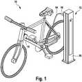
- Fig. 1is a perspective view of a bicycle at a security and / or charging station shown schematically.
- the bicycleis generally designated 10 and the securing and / or charging station is generally designated 12.
- the bicycle 10has a securing device 14, by means of which the bicycle 10 is firmly and detachably connected to the securing and / or charging station 12.
- the securing device 14forms an anti-theft device for the bicycle 10 and is designed as an elongated flexible securing device with a connecting plug 16 which can be detachably connected to a socket (not shown here) of the securing and / or charging station 12.
- the securing device 14is fixedly connected to the bicycle 10 by means of a connecting section 18, so that the securing device 14 forms a mechanical connection between the bicycle 10 and the securing and / or charging station 12.
- the bicycle 10only has a pedal crank drive, so that the securing device 14 in this embodiment only serves to secure the bicycle 10 and forms an anti-theft device for the bicycle 10.
- the bicycle 10can also have an electric drive with a corresponding electrical energy store, the securing device 14 then serves both as an anti-theft device and as a cable for exchanging electrical energy with the electrical energy store.
- the securing and / or charging station 12can accordingly form both only a mechanical securing station and a securing and charging station for charging or discharging the electrical energy store.
- the backup and / or charging station 12is as shown in Fig. 1 is shown, a stationary station with a corresponding housing 20, which is fixedly anchored in the ground.
- the plug connector 16has a radio transmission unit and the securing and / or charging station 12 has a corresponding radio receiving unit, so that data, in particular for identifying the bicycle 10, is transmitted from the plug connector 16 of the securing device 14 to the securing and / or charging station 12 can be.
- a cut-off of the connection between the plug connector 16 and the connecting section 18can be detected by a control unit in the security device 14 and transmitted to the security and / or charging station 12 via the radio transmission unit, so that a corresponding theft of the bicycle 10 is detected and transmitted can be.
- camerascan be activated, for example, or a time of theft can be saved, so that the theft can be traced accordingly.
- a reliable and universal data transmissioncan be ensured by the radio transmission of the data from the plug connector 16 to the securing and / or charging station 12 that data can be transmitted independently of a specific connector system.
- a plug connection between the securing device 14 and the securing and / or charging station 12is shown in perspective and generally designated 22.
- the plug connection 22is formed by the plug connector 16 of the securing device 14 and a plug socket 24 of the securing and / or charging station 12.
- the plug connection 22is designed both to secure the bicycle 10 at the securing and charging station 12 and to charge or discharge the energy store, as will be explained in more detail below.
- the plug connector 16has a housing 26 in which the radio transmission unit (not shown here in more detail) is arranged in order to transmit data from the security device 14 to the security and / or charging station 12.
- the connector 16has a locking section 28 which is partially arranged in the housing 26 in order to fix the connector 16 in the socket 24 and to secure it accordingly.
- the securing device 14also has an elongated securing element 30, which forms a flexible mechanical connection and is preferably designed as a steel cable or steel chain. In this embodiment, parallel to the fuse element 30, three electrical lines 32 for the transmission of electrical energy are also arranged, the contacts of the connector 16 with the electrical Connect energy storage in order to charge or discharge it accordingly.
- a plurality of data lines 34are arranged or guided parallel to the securing element 30 in order to transmit data signals from the bicycle 10 or from electrical components of the bicycle 10 to the securing and / or charging station 12 in general, by means of the radio transmission unit .
- the data lines 34also serve to detect a severing of the fuse element 30 and to correspondingly transmit it to the fuse and / or charging station 12 by means of the radio transmission unit.
- the connector 16also has a plurality of electrical contacts 36 which are electrically connected to the electrical lines 32 in order to transmit electrical energy on the electrical energy storage device of the bicycle 10.
- the socket 24, which is complementary to the plug connector 16 and is shaped in such a way that the plug connector 16 can be inserted into the socket 24,has a housing 38 in which electrical contacts 40 are arranged.
- the electrical contacts 40are correspondingly connected or connectable to an electrical energy source in order to provide electrical energy at the electrical contacts 40 and thus to charge an electrical energy store of the bicycle 10.
- a locking device 42is also accommodated, which is designed to lock or fix the locking section 28 accordingly, so as to establish a mechanical fixed connection between the plug connector 16 and the Form socket 24.
- a radio receiving unit 44which forms a radio link for wireless data transmission with the radio transmission unit of the connector 16 and correspondingly receives data from the connector 16.
- the locking device 42is an electrical locking device and can accordingly be actuated by an electrical signal, that is, closed or opened.
- an electrical signalthat is, closed or opened.
- Fig. 3is a schematic view of the connector 22 from Fig. 2 shown.
- the same elementsare designated with the same reference numbers, only the special features being explained here.
- the plug connector 16has the radio transmission unit 46 which is arranged in the housing 26 in order to transmit data 48 in the form of radio signals to the radio reception unit 44 of the socket 24.
- the radio transmission unit 46is connected to a control unit 50 and to the data lines 34 in order to transmit the data 48 accordingly.
- the data lines 34form data lines of a mobile bus system 52 of the bicycle 10, which is preferably designed as a CAN bus.
- the radio transmission unit 46forms an external interface of the bus system 52 or a gateway of the CAN bus.
- the radio transmission unit 46can also transmit identification data for identifying the vehicle 10 to the station 12, the identification data preferably being stored in a memory 55 in the connector.
- Connector 16has individual identification data, so that each connector 16 can be uniquely identified electronically. As a result, each bicycle 10 can be clearly identified electronically at station 12.
- the locking device 42 and a control unit 54are arranged in the housing 38 of the socket 24, the control unit 54 controlling the radio receiving unit 44 and the locking device 42.
- the control unit 54 and the radio reception unit 44are connected to a stationary bus system 56, which is preferably designed as a stationary CAN bus.
- the radio reception unit 44correspondingly forms an external interface of the bus system 56 or a gateway of the stationary CAN bus.
- the electrical contacts 36 of the plug connector 16are connected to the electrical lines 32, the electrical lines being formed by a ground line 58, a first voltage line 60 (+ 60 V) and optionally a second voltage line 62 ( ⁇ 120 V).
- the electrical contacts 40 of the socket 24are connected to electrical lines 64, which are connected or can be connected to an electrical energy source or a voltage converter, in order to provide corresponding electrical voltages and corresponding electrical power at the electrical contacts 40. Due to the three voltage potentials 0V, + 60V, - 120V, three different voltages, namely 60V, 120V and 180V, can be provided on the contacts.
- the wireless transmission of the data 48enables a universal data interface between the plug connector 16 and the securing and / or charging station 12.
- the electrical control of the radio transmission unit 46 of the locking section 28can be used to release an electrical signal such as an RFID transponder signal or another electrical signal, so that the connection of the bicycle 10 to the securing and / or charging station 12 is simple and can be solved with an appropriate authentication.
- the electrical connection of the electrical contacts 40can be disconnected from the energy source, so that overvoltages and arcing can be avoided when the connector 16 is disconnected from the socket 24.
- the bus system 56can be connected or connectable to a cloud service or, for example, via the Internet a database and / or an authentication program to be connected or connectable, for example, to ensure payment of the electrical energy or a parking security fee.
- the data of each clearly identifiable connector or bicycleis transferred to the database and stored and can be statistically (technically or economically) evaluated. Via the database, clear assignments of manufacturers, owners, users and usage-dependent data can be created and evaluated technically and economically.
- Electrical properties of the plug connector and / or of the connected energy storecan also be transmitted via the wireless connection, such as e.g. Max. Voltage, current, power, state of charge etc.
- a temperature sensorcan also be arranged in the plug connector 16 or on the data lines 34 in order to detect an ambient temperature or a temperature of the components of the safety device 16.
- critical temperatureswhich can arise as a result of overloading, defects, aging or wear of the components under different framework conditions, can be recorded and taken into account when transmitting electrical energy.
- temperature-controlled power controlis possible.
- Fig. 4a perspective view of the connector 16 without the housing 26 is shown.
- the same elementsare designated with the same reference numbers, only the special features being explained here.
- the plug connectorhas no electrical contacts and, accordingly, no electrical lines 32.
- the locking section 28is guided through the entire housing 26 and firmly connected to the elongated securing element 30, which in this embodiment is designed as a steel cable.
- a secure connectioncan be formed between the locking section 28 or the locking device 42 and the connecting section 18, so that a secure mechanical connection between the bicycle and the securing and / or charging station 12 can be provided.
- the data lines 34which both form part of the mobile bus system 52 and also serve to detect a severing of the elongated securing element 30, are routed parallel to the elongated securing element 30. This detection can be carried out, for example, by a simple electrical continuity measurement by the control unit 50.
- the radio transmission unit 46which is designed as a near-field radio transmission unit, has a coil which is an antenna element of the Radio transmission unit 46 forms.
- the radio transmission unit 46is preferably designed as a transmitting and receiving unit in order to appropriately transmit and receive radio signals.
- the coil 66is also connected to electrical components in the housing 26 of the connector 16 in order to supply the electrical elements, such as the control unit 50, with electrical energy.
- Fig. 5is a perspective view of the securing device 14 is shown, wherein the in Fig. 5 embodiment shown has no electrical contacts 36.
- the same elementsare designated with the same reference symbols, only the special features being explained here.
- the connecting section 18has a housing 68 which can be fixedly connected to a frame of the bicycle 10 with screws, one end of the securing element 30 being fixedly connected to the housing 68, so as to provide a mechanically stable connection between the connecting section 18 and the locking section 28 to form and accordingly fix the bicycle 10 securely to the securing and / or charging station 12.
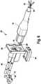
- Fig. 6an exploded perspective view of the socket 24 is shown together with the connector 16.
- the same elementsare designated with the same reference symbols, only the special features being explained here.
- the radio reception unit 44is arranged below a receptacle 70 for the plug connector 16, so that the radio reception unit 44, which preferably has a coil as an antenna element, is arranged directly below the coil 66 of the plug connector 16 in the plugged-in state of the plug connection 22, so that an ideal transmission of electromagnetic waves is possible.
- the radio receiving unit 44is preferably designed as a transmitting and receiving unit in order to both transmit and receive data, so that the data 48 can be exchanged bidirectionally between the plug connector 16 and the socket 24 or the securing and / or charging station 12.
- the locking device 42is arranged below the receptacle 70 for the plug connector 16 and has a locking pin 72 which can engage in the locking section 28 in order to prevent the plug connector 16 from coming loose from the plug socket 24 and to provide a fixed, locked connection between the plug connector 16 and to form the socket 24. Due to the special arrangement of the coil of the radio receiver unit 44, electromagnetic energy can also be transmitted to the coil 66 in addition to the data 48, so that the electrical components in the housing 26 of the plug connector 16 can be supplied with electrical energy.
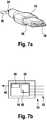
- Fig. 7ais a perspective view of the connector 16 is shown in a simplest embodiment.
- the connector 16only has the Locking section 28 and the radio transmission unit 46 in order to correspondingly transmit the data 28 to the securing and / or charging station 12 and to connect the securing device 14 to the securing and / or charging station 12 accordingly.
- the data lines 34which form part of the bus system 52, usually have two bus lines (high, low), a low-voltage line and a ground line.
- the radio transmission unit 46is designed as a near-field radio transmission unit and transmits the data 48 to the security and / or charging station 12 as described above.
- the plug connectors 16each have the locking section 28 and additionally two of the electrical contacts 36, as shown in FIG Fig. 8a or three of the electrical contacts 36, as shown in Fig. 8b is shown.
- the embodiment from Fig. 8apreferably has a +60 volt contact 60 and a ground contact 58 in order to charge electrical energy stores of bicycles such as pedelegs and light electric vehicles (LEVs).
- bicyclessuch as pedelegs and light electric vehicles (LEVs).
- the connector 16 from Fig. 8bhas a -120 volt contact 62, a +60 volt contact 60 and one Ground contact 58 and serves, for example, to supply electrically powered motorcycles or electrically driven motor vehicles with larger electrical energy stores and greater energy consumption with electrical energy.
- the securing device 14can thus serve in its simplest form only to secure the bicycle 10 and in alternative embodiments to charge electrical energy stores with a low voltage such as +60 volts or a higher voltage such as 180 volts.
- FIG. 9A special embodiment of the securing device 14 or the connecting section 18 is shown in perspective. The same elements are designated with the same reference symbols, only the special features being explained here.
- the housing 68 of the connecting section 18, which is fixed to a frame of the bicycle 10 and correspondingly forms a fixed connection to the bicycle 10,has a socket 74 which corresponds in its mechanical dimensions to the socket 24 or a complementary receptacle for the connector 16 forms.
- the connector 16can be inserted into the socket 74 and fixed in the socket 74 by means of a locking device, not shown here. This allows the connector 16 to be secured while driving with little effort.
- a simple embodiment of the securing device 14can be provided by the socket 24 by the Security device 14, provided there is no security and / or charging station 12, is placed around a solid object and is fixed and secured in the socket 74 so that a conditional mechanical theft protection can be achieved.
- the socket 74 or the housing 68has a corresponding control for this, which controls the locking device and can be released or unlocked, for example, by means of a radio signal, such as an RFID signal or another radio signal. An authenticated release of the plug connector 16 from the plug socket 74 of the connecting section 18 is thereby possible.
- Fig. 10is the embodiment of the safety device 14 from Fig. 9 shown in perspective in an attached state on the bicycle 10.
- the bicycle 10can thus be easily secured if there is no securing and / or charging station 12 and the connector 16 can be stably mounted on the frame of the bicycle 10 while driving.
- Fig. 1 1 14is an exploded view of the connector section 18 Fig. 9 shown in perspective.
- the same elementsare designated with the same reference numbers, only the special features being explained here.
- the socket 74is arranged in the housing 68 and has a receptacle 76 which is complementary to the plug connector 16.
- the locking device 78is assigned to the receptacle 76 and is controlled by a control unit 80 can be in order to fix and lock the locking portion 28 in the receptacle 76 accordingly.
- the socket 74also has a near-field radio reception unit 82, preferably with a coil, in order to receive corresponding control signals, so that the locking device 78 can be controlled or released, for example, by means of an RFID transponder or another radio signal.
- Fig. 12a schematic block diagram of the backup and / or charging station 12 is shown. The same elements are designated with the same reference symbols, only the special features being explained here.
- the backup and / or charging station 12is in Fig. 12 schematically shown with two sockets 24, it being understood that the station 12 can also have a plurality of further sockets 24 or charging stations.
- the securing and / or charging station 12has a connection interface 84, at which an interface 86 for electrical energy and an interface 88 for the bus system 56 are formed.
- the electrical energyis in each case converted into different voltages by means of a DC voltage converter 90, 92 and is accordingly provided at the electrical contacts 40, as explained in detail above.
- the bus system 56is connected to the radio receiver units 44 and the control units 54, respectively connected to receive the data 48 and to feed it into the bus system 56 accordingly.
- the bus system 56is connected to the DC-DC converters 90, 92 in order to control the DC-DC converters 90, 92 accordingly and, for example, to provide a correspondingly necessary voltage and, for example, to interrupt the voltage supply before the locking device 42 is released in order to prevent arcing on the contacts 40 ("Hot-plugging") to avoid.
- a further radio unit 94can be connected to the bus system 56, which, for example, can receive a radio signal from a mobile telephone or the like and can accordingly release the locking device 42, provided that a corresponding authentication via the radio signals is received at the radio unit 94.
- the radio unit 94can also provide WiFi as a hotspot.
- the bus system 56is or can be connected via the interface 88 to the Internet in order to receive information from a database or a cloud service and, for example, to serve for authentication of the user and, for example, to pay for the electrical energy transmitted. Furthermore, if the securing element 30 is cut through, all relevant data can be correspondingly transmitted via the interface 88, in order subsequently to facilitate tracking.
Landscapes
- Engineering & Computer Science (AREA)
- Mechanical Engineering (AREA)
- Power Engineering (AREA)
- Transportation (AREA)
- Details Of Connecting Devices For Male And Female Coupling (AREA)
- Charge And Discharge Circuits For Batteries Or The Like (AREA)
Description
Translated fromGermanDie vorliegende Erfindung betrifft eine Sicherungsvorrichtung für ein Fahrzeug, insbesondere für ein Fahrrad und/oder ein Elektrofahrrad, mit den Merkmalen des Oberbegriffs von Anspruch 1.The present invention relates to a safety device for a vehicle, in particular for a bicycle and / or an electric bicycle, with the features of the preamble of claim 1.
Die vorliegende Erfindung betrifft ferner eine Befestigungsvorrichtung zum Sichern von Fahrzeugen, insbesondere von Fahrrädern und/oder Elektrofahrrädern, die Bestandteil eines Sicherungssystems bildet..The present invention further relates to a fastening device for securing vehicles, in particular bicycles and / or electric bicycles, which forms part of a security system.
Die vorliegende Erfindung betrifft ferner ein Sicherungssystem zum mechanischen Sichern von Fahrzeugen, insbesondere von Fahrrädern, mit einer Sicherungsvorrichtung, die mit einem Fahrzeug verbunden ist und mit einer Befestigungsvorrichtung, die einen Teil einer ortsfesten Station bildet.The present invention further relates to a security system for mechanically securing vehicles, in particular bicycles, with a securing device which is connected to a vehicle and with a fastening device which forms part of a stationary station.
Derartige Sicherungsvorrichtungen dienen dazu, ein Fahrzeug, insbesondere ein Fahrrad, an einer entsprechenden Befestigungsvorrichtung, insbesondere einer ortsfesten Befestigungsstation, festzulegen, um ein nicht autorisiertes Benutzen des Fahrzeugs zu verhindern.Such securing devices serve to secure a vehicle, in particular a bicycle, to a corresponding fastening device, in particular a stationary fastening station, in order to prevent unauthorized use of the vehicle.
Aus dem Stand der Technik ist es allgemein bekannt, Fahrzeuge, insbesondere Fahrräder, mit einem elektrischen Antrieb an zentralen Ladestationen anzuschließen, um einen elektrischen Energiespeicher des Fahrrads mit elektrischer Energie zu versorgen und aufzuladen. Es ist weiterhin bekannt, die Fahrräder an der Ladestation mittels eines kombinierten Lade-Schloss-Kabels elektrisch mit der Ladestation zu verbinden und gleichzeitig mechanisch an der Ladestation zu sichern, um die Fahrräder vor Diebstahl zu schützen. Ein entsprechendes System ist beispielsweise aus der
Es ist weiterhin bekannt, über das Ladekabel Daten mit der Ladestation auszutauschen, um beispielsweise ein Bezahlungssystem zum Bezahlen der übertragenen elektrischen Energie bereitzustellen oder andere fahrzeugrelevante Daten zu übermitteln.It is also known to exchange data with the charging station via the charging cable, for example in order to use a payment system to pay for the electrical data transmitted To provide energy or to transmit other vehicle-related data.
Nachteilig bei den bekannten Lade-Schloss-Kabeln und Lade-Schloss-Systemen ist es, dass die Datenübermittlung kompliziert ist und standardisierte Datenkabel und Datenstecker benötigen, um ein universelles Laden und eine universelle Datenübertragung zu bieten. Weiterhin ist es nachteilig, dass die vielfache Verbindung der Datenstecker mit der Station zu einer Abnutzung der Steckverbindung und somit dauerhaft zu einer Beschädigung führt.A disadvantage of the known charging lock cables and charging lock systems is that the data transmission is complicated and requires standardized data cables and data plugs in order to offer universal charging and data transmission. It is also disadvantageous that the multiple connection of the data plugs to the station leads to wear of the plug connection and thus permanent damage.
Es ist daher die Aufgabe der vorliegenden Erfindung, eine Sicherungsvorrichtung für ein Fahrzeug bereitzustellen, die eine vereinfachte und universelle Sicherung des Fahrzeugs mit der Station bietet. Es ist ferner die Aufgabe der vorliegenden Erfindung, ein entsprechendes verbessertes Sicherungssystem zum mechanischen Sichern von Fahrzeugen bereitzustellen.It is therefore the object of the present invention to provide a securing device for a vehicle which offers a simplified and universal securing of the vehicle with the station. It is also the object of the present invention to provide a correspondingly improved security system for mechanically securing vehicles.
Diese Aufgabe wird durch eine Sicherungsvorrichtung mit den Merkmalen des Anspruchs 1 gelöst.This object is achieved by a safety device with the features of claim 1.
Diese Aufgabe wird durch ein Sicherungssystem zum mechanischen Sichern von Fahrzeugen mit den Merkmalen des Anspruchs 10 gelöst.This object is achieved by a security system for mechanically securing vehicles with the features of
Prinzipiell ist das Verbindungselement der Sicherungsvorrichtung dazu ausgebildet, mit dem Verbindungselement der Befestigungsvorrichtung eine Verbindungseinheit zu bilden und entsprechend an der Befestigungsvorrichtung mittels der Verriegelungsvorrichtung festgelegt zu werden, um eine mechanisch feste Verbindung zwischen der Befestigungsvorrichtung und dem Fahrzeug zu bilden, so dass das Fahrzeug entsprechend vor einer nicht autorisierten Benutzung geschützt ist. Dadurch, dass die Sicherungsvorrichtung die Übertragungseinheit als Funkübertragungseinheit aufweist und die Befestigungsvorrichtung die Empfangseinheit als Funkempfangseinheit aufweist, können zwischen der Sicherungsvorrichtung und der Befestigungsvorrichtung die Signale als Funksignale übertragen bzw. ausgetauscht werden, so dass eine technisch aufwendige, komplizierte und anfällige Datenübertragung mittels Datensteckern bzw. Datenleitungen entfällt und eine komfortable, einfache und universelle Datenübertragung zwischen der Sicherungsvorrichtung und der Befestigungsvorrichtung möglich ist.In principle, the connecting element of the securing device is designed to be one with the connecting element of the fastening device To form a connecting unit and to be fixed accordingly to the fastening device by means of the locking device in order to form a mechanically fixed connection between the fastening device and the vehicle, so that the vehicle is accordingly protected against unauthorized use. Because the securing device has the transmission unit as a radio transmission unit and the fastening device has the receiving unit as a radio receiving unit, the signals can be transmitted or exchanged as radio signals between the securing device and the fastening device, so that technically complex, complicated and susceptible data transmission by means of data plugs or Data lines are omitted and comfortable, simple and universal data transmission between the securing device and the fastening device is possible.
Die Verbindungseinheit ist als Steckverbindung ausgebildet. Die Steckverbindung weist insbesondere einen Steckverbinder und eine Steckbuchse auf.The connection unit is designed as a plug connection. The plug connection has in particular a plug connector and a socket.
Dadurch können die beiden Verbindungsglieder mit geringem Aufwand präzise miteinander verbunden werden.As a result, the two connecting links can be precisely connected to one another with little effort.
In einer bevorzugten Ausführungsform der Sicherungsvorrichtung ist die Übertragungseinheit mit einem mobilen Bus-System des Fahrzeugs verbunden.In a preferred embodiment of the security device, the transmission unit is connected to a mobile bus system of the vehicle.
Dadurch können entsprechend Daten von unterschiedlichen elektrischen Elementen und Systemen des Fahrzeugs mit der Station ausgetauscht werden. In einer besonders bevorzugten Ausführungsform ist das Bus-System des Fahrzeugs als CAN-Datenbus ausgebildet, wodurch ein einfacher standardisierter Datenaustausch zwischen unterschiedlichen elektrischen Systemen des Fahrzeugs und der Station möglich ist.As a result, data from different electrical elements and systems of the vehicle can be exchanged with the station accordingly. In a particularly preferred embodiment, the bus system of the vehicle is designed as a CAN data bus, as a result of which a simple standardized data exchange between different electrical systems of the vehicle and the station is possible.
Dabei ist es besonders bevorzugt, wenn die Übertragungseinheit eine äußere Schnittstelle des mobilen Bus-Systems bildet. Insbesondere bildet die Übertragungseinheit ein Gateway als äußere Schnittstelle des mobilen Bus-Systems, wobei im angeschlossenen Zustand der Sicherungsvorrichtung die Übertragungseinheit ein Gateway zwischen zwei unterschiedlichen Bus-Systemen und insbesondere ein Gateway zwischen zwei separaten CAN-Bus-Systemen bildet.It is particularly preferred if the transmission unit forms an external interface of the mobile bus system. In particular, the transmission unit forms a gateway as the external interface of the mobile bus system, the transmission unit forming a gateway between two different bus systems and in particular a gateway between two separate CAN bus systems when the safety device is connected.
Dadurch ist eine definierte Schnittstelle zwischen dem mobilen Bus-System des Fahrzeugs und einem stationären Bus-System möglich, die einen definierten Austausch von Daten ermöglicht.This enables a defined interface between the vehicle's mobile bus system and a stationary bus system, which enables a defined exchange of data.
Weiter weist die Sicherungsvorrichtung eine Steuereinheit auf, die mit der Übertragungseinheit verbunden ist, um die Signalübertragung zu steuern.Furthermore, the securing device has a control unit which is connected to the transmission unit in order to control the signal transmission.
Dadurch kann mit technisch geringem Aufwand eine zuverlässige Übertragung von Daten von dem Verbindungselement auf das komplementäre Verbindungselement ermöglicht werden.This allows reliable transmission of data from the Connecting element to the complementary connecting element are made possible.
Es ist weiterhin bevorzugt, wenn die Übertragungseinheit als Nahfeldfunkeinheit ausgebildet ist.It is further preferred if the transmission unit is designed as a near field radio unit.
Dadurch können die Funksignale von der Übertragungseinheit auf benachbarte oder nahe Empfangseinheiten übertragen werden, so dass eine geringe elektrische Leistung für die Funkübertragung notwendig ist und gleichzeitig umliegende elektrische Geräte nicht beeinflusst werden.As a result, the radio signals can be transmitted from the transmission unit to neighboring or nearby reception units, so that a low electrical power is necessary for the radio transmission and at the same time surrounding electrical devices are not influenced.
Es ist weiterhin bevorzugt, wenn die Übertragungseinheit und die Steuereinheit dazu ausgebildet sind, Identifikationsdaten der Sicherungsvorrichtung und/oder des Fahrzeugs zu übertragen.It is further preferred if the transmission unit and the control unit are designed to transmit identification data of the security device and / or of the vehicle.
Dadurch kann die Sicherheit des verbundenen Fahrzeugs weiterhin erhöht werden, da eine Speicherung der Verbindungszeiträume des jeweiligen Fahrzeugs möglich ist.This further increases the security of the connected vehicle, since it is possible to save the connection periods of the respective vehicle.
Vorzugsweise sind die Identifikationsdaten in einem Speicher in dem Verbindungselement gespeichert, das der Steuereinheit zugeordnet ist.The identification data are preferably stored in a memory in the connecting element which is assigned to the control unit.
Außerdem weist die Übertragungseinheit eine Spule auf, die dazu ausgebildet ist, die Funksignale zu übertragen.In addition, the transmission unit has a coil which is designed to transmit the radio signals.
Dadurch kann mit technisch geringem Aufwand eine effektive Übertragung der Funksignale gewährleistet werden.This enables effective transmission of the radio signals to be ensured with little technical effort.
Zudem ist die Spule mit der Steuereinheit elektrisch verbunden, um die Steuereinheit mit elektrischer Energie zu versorgen.In addition, the coil is electrically connected to the control unit in order to supply the control unit with electrical energy.
Dadurch kann mit technisch geringem Aufwand eine elektrische Energieversorgung der Steuereinheit gewährleistet werden und gleichzeitig auf einen gesonderten Energiespeicher in der Sicherungsvorrichtung bzw. in dem Verbindungselement verzichtet werden.As a result, an electrical energy supply to the control unit can be guaranteed with little technical effort and, at the same time, a separate energy store in the securing device or in the connecting element can be dispensed with.
Es ist weiterhin bevorzugt, wenn die Sicherungsvorrichtung wenigstens eine Datenleitung aufweist, die parallel zu dem langgestreckten Sicherungselement geführt ist, wobei die Steuereinheit mit der Datenleitung verbunden ist und dazu ausgebildet ist, die Verbindung des Verbindungselements mit dem Verbindungsabschnitt über die Datenleitung zu prüfen.It is further preferred if the securing device has at least one data line which is guided parallel to the elongated securing element, the control unit being connected to the data line and being designed to test the connection of the connecting element to the connecting section via the data line.
Dadurch kann ein Durchtrennen des Sicherungselements von der Steuereinheit erfasst werden, da die parallel zu dem Sicherungselement geführte Datenleitung zusammen mit dem Sicherungselement durchtrennt werden muss, so dass ein entsprechend unautorisiertes Entfernen des Fahrzeugs erfasst werden kann. In einer einfachen Ausführungsform wird zur Prüfung der Verbindung zwischen dem Verbindungselement und dem Verbindungsabschnitt lediglich eine elektrische Durchgangsprüfung durchgeführt.A cut-through of the security element can thereby be detected by the control unit, since the data line running parallel to the security element must be severed together with the security element, so that a correspondingly unauthorized removal of the vehicle can be detected. In a simple embodiment, only an electrical continuity test is carried out to test the connection between the connecting element and the connecting section.
In einer bevorzugten Ausführungsform ist die Steuereinheit dazu ausgebildet, eine Unterbrechung der Verbindung des Verbindungselements mit dem Verbindungsabschnitt zu erfassen und ein entsprechendes Signal über die Übertragungseinheit an eine Empfangseinheit des komplementären Verbindungselements zu übermitteln.In a preferred embodiment, the control unit is designed to detect an interruption in the connection of the connecting element to the connecting section and a corresponding signal via the To transmit transmission unit to a receiving unit of the complementary connecting element.
Dadurch kann ein nicht autorisiertes Entfernen des Fahrzeugs gemeldet werden und entsprechend Maßnahmen wie z.B. ein Alarm oder eine Videoaufzeichnung initiiert werden.This enables unauthorized removal of the vehicle to be reported and appropriate measures such as an alarm or video recording is initiated.
In einer bevorzugten Ausführungsform weist die Sicherungsvorrichtung eine Mehrzahl von elektrischen Leitungen auf, die jeweils mit einem elektrischen Kontakt des Verbindungselements und mit einem elektrischen Kontakt des Verbindungsabschnitts verbunden sind, um elektrische Energie auf einen Energiespeicher des Fahrzeugs zu übertragen oder mit einem Energiespeicher des Fahrzeugs auszutauschen.In a preferred embodiment, the securing device has a plurality of electrical lines, each of which is connected to an electrical contact of the connecting element and to an electrical contact of the connecting section, in order to transmit electrical energy to an energy store of the vehicle or to exchange it with an energy store of the vehicle.
Dadurch kann über die Sicherungsvorrichtung gleichzeitig elektrische Energie auf den Energiespeicher des Fahrzeugs oder von dem Energiespeicher des Fahrzeugs übertragen werden, so dass der Energiespeicher des Fahrzeugs im gesicherten Zustand geladen oder entladen werden kann.As a result, electrical energy can simultaneously be transmitted to the energy storage device of the vehicle or from the energy storage device of the vehicle via the securing device, so that the energy storage device of the vehicle can be charged or discharged in the secured state.
Es ist weiterhin bevorzugt, wenn der Verbindungsabschnitt dazu ausgebildet ist, an dem Fahrzeug festgelegt zu werden und mit dem Fahrzeug eine mechanisch feste Verbindung zu bilden.It is further preferred if the connecting section is designed to be fixed to the vehicle and to form a mechanically fixed connection with the vehicle.
Dadurch kann die Sicherungsvorrichtung eine feste Einheit mit dem Fahrzeug bilden, so dass ein einfaches Verbinden mit dem komplementären Verbindungselement eine sichere und mechanisch feste Verbindung des Fahrzeugs zu einer stationären Sicherungsstation bildet.As a result, the securing device can form a fixed unit with the vehicle, so that a simple connection with the complementary connecting element ensures a secure and forms a mechanically fixed connection between the vehicle and a stationary security station.
Außerdem weist der Verbindungsabschnitt ein komplementäres Verbindungselement mit einer Verriegelungsvorrichtung auf, um den Verriegelungsabschnitt des Verbindungselements an dem Verbindungsabschnitt festzulegen.In addition, the connecting section has a complementary connecting element with a locking device in order to fix the locking section of the connecting element to the connecting section.
Dadurch kann das Verbindungselement zum einen sicher und mechanisch stabil an dem Fahrzeug befestigt werden und gleichzeitig kann eine universelle Sicherungsvorrichtung bereitgestellt werden, da das langgestreckte Sicherungselement lediglich um einen ortsfesten Gegenstand herumgeführt werden muss, um das Fahrzeug zu sichern.As a result, the connecting element can be securely and mechanically stably fastened to the vehicle, and at the same time a universal securing device can be provided, since the elongated securing element only has to be guided around a stationary object in order to secure the vehicle.
Weiter weist der Verbindungsabschnitt eine Funkempfangseinheit auf, um Funksignale zu empfangen.Furthermore, the connection section has a radio receiving unit in order to receive radio signals.
Dadurch kann ein entsprechendes Signal auf den Verbindungsabschnitt übertragen werden, um beispielsweise ein Öffnen und ein Schließen der Verriegelungsvorrichtung zu initiieren.As a result, a corresponding signal can be transmitted to the connecting section, for example to initiate opening and closing of the locking device.
Weiterhin ist die Verriegelungsvorrichtung als elektrisch betätigbare Verriegelungsvorrichtung ausgebildet.Furthermore, the locking device is designed as an electrically actuated locking device.
Dadurch kann der Verriegelungsabschnitt einfach und sicher an dem Verbindungsabschnitt festgelegt werden.As a result, the locking section can be fixed simply and securely to the connecting section.
Es ist weiterhin bevorzugt, wenn die Übertragungseinheit als Sende-und Empfangseinheit ausgebildet ist, um Funksignale zu senden und zu empfangen.It is further preferred if the transmission unit is designed as a transmitting and receiving unit in order to transmit and receive radio signals.
Dadurch ist ein zweiseitiger Austausch von Daten zwischen dem Verbindungselement und dem komplementären Verbindungselement möglich, so dass ein beliebiger Austausch von Informationen möglich ist.This enables a two-way exchange of data between the connecting element and the complementary connecting element, so that any exchange of information is possible.
In einer bevorzugten Ausführungsform weist die Befestigungsvorrichtung ein Gehäuse auf, das eine ortsfeste Sicherungsstation bildet.In a preferred embodiment, the fastening device has a housing which forms a stationary securing station.
Dadurch kann eine ortsfeste Verbindung für die Sicherungsvorrichtung bereitgestellt werden, so dass das Fahrzeug an der Befestigungsvorrichtung sicher und ortsfest festgelegt werden kann.As a result, a fixed connection can be provided for the securing device, so that the vehicle can be securely and fixedly attached to the fastening device.
Es ist weiterhin bevorzugt, wenn die Empfangseinheit mit einem ortsfesten Bus-System verbunden ist.It is further preferred if the receiving unit is connected to a stationary bus system.
Dadurch können mit technisch geringem Aufwand Steuerdaten mit unterschiedlichen elektrischen Systemen der Befestigungsvorrichtung ausgetauscht werden, wodurch ein universelles und beliebig erweiterbares System gebildet werden kann.As a result, control data can be exchanged with different electrical systems of the fastening device with little technical effort, as a result of which a universal and arbitrarily expandable system can be formed.
Es ist dabei besonders bevorzugt, wenn die Empfangseinheit eine äußere Schnittstelle zu dem ortsfesten Bus-System bildet.It is particularly preferred if the receiving unit forms an external interface to the fixed bus system.
Dadurch kann eine definierte und zuverlässige Schnittstelle zu einem mobilen Bus-System bereitgestellt werden, wodurch ein zuverlässiger Austausch von Daten über die Empfangseinheit möglich ist.As a result, a defined and reliable interface to a mobile bus system can be provided, which enables a reliable exchange of data via the receiving unit.
Es ist weiterhin bevorzugt, wenn das Bus-System ein CAN-Bus-System ist. Dadurch ist ein standardisierter Datenaustausch mit dem Fahrzeug möglich.It is further preferred if the bus system is a CAN bus system. This enables standardized data exchange with the vehicle.
Es ist weiterhin bevorzugt, wenn die Funkempfangseinheit eine äußere Schnittstelle des Bus-Systems und insbesondere ein Gateway des CAN-Buses bildet.It is further preferred if the radio receiving unit forms an external interface of the bus system and in particular a gateway of the CAN bus.
Es ist weiterhin bevorzugt, wenn der Empfangseinheit eine Steuereinheit zugeordnet ist, um die empfangenen Funksignale zu verarbeiten.It is further preferred if a control unit is assigned to the receiving unit in order to process the received radio signals.
Dadurch ist eine zuverlässige Übertragung von Funksignalen mit technisch geringem Aufwand möglich.This enables reliable transmission of radio signals with little technical effort.
Es ist weiterhin bevorzugt, wenn die Verriegelungsvorrichtung als elektrisch betätigbare Verriegelungsvorrichtung ausgebildet ist.It is further preferred if the locking device is designed as an electrically actuable locking device.
Dadurch kann die Verriegelungsvorrichtung zuverlässig und mit technisch geringem Aufwand komfortabel geschlossen und geöffnet werden.As a result, the locking device can be closed and opened reliably and with little technical effort.
Dabei ist es besonders bevorzugt, wenn die Steuereinheit mit der Verriegelungsvorrichtung verbunden ist, um die Verriegelungsvorrichtung zu betätigen. [0062] Dadurch kann ein sicheres und autorisiertes Öffnen und Schließen der Verriegelungsvorrichtung ermöglicht werden.It is particularly preferred if the control unit is connected to the locking device in order to actuate the locking device. [0062] This enables safe and authorized opening and closing of the locking device.
Es ist dabei besonders bevorzugt, wenn der Steuereinheit eine Eingabeeinheit zugeordnet ist, um der Steuereinheit ein Steuersignal zuzuführen, und wobei die Steuereinheit dazu ausgebildet ist, auf der Grundlage des Steuersignals die Verriegelungsvorrichtung zu betätigen.It is particularly preferred if the control unit is assigned an input unit in order to supply the control unit with a control signal, and the control unit is designed to actuate the locking device on the basis of the control signal.
Dadurch kann die Verriegelungsvorrichtung komfortabel und gleichzeitig sicher betätigt werden, so dass ein komfortables und zuverlässiges Öffnen und Schließen der Verriegelungsvorrichtung möglich ist.As a result, the locking device can be operated comfortably and at the same time securely, so that the locking device can be opened and closed in a comfortable and reliable manner.
Es ist dabei besonders bevorzugt, wenn die Eingabeeinheit eine Funkeingabeeinheit ist bzw. durch die Funkempfangseinheit gebildet ist, so dass ein Öffnen der Verriegelungsvorrichtung beispielsweise durch einen mobilen Transponder insbesondere mittels RFID oder durch eine mobile Funkvorrichtung wie z.B. ein Mobiltelefon möglich ist.It is particularly preferred if the input unit is a radio input unit or is formed by the radio receiving unit, so that the locking device is opened, for example, by a mobile transponder, in particular by means of RFID or by a mobile radio device, such as e.g. a mobile phone is possible.
Es ist weiterhin bevorzugt, wenn die Empfangseinheit eine Spule aufweist, um die Funksignale zu empfangen und elektrische Energie auf das komplementäre Verbindungselement zu übertragen.It is further preferred if the receiving unit has a coil in order to receive the radio signals and to transmit electrical energy to the complementary connecting element.
Dadurch kann zum einen mit technisch geringem Aufwand eine Antenne bereitgestellt werden und gleichzeitig die Antenne genutzt werden, um elektrische Energie auf das komplementäre Verbindungselement zu übertragen, so dass in dem komplementären Verbindungselement eine elektrische Energieversorgung mit technisch geringem Aufwand möglich ist.In this way, on the one hand, an antenna can be provided with little technical effort and at the same time the antenna can be used to transmit electrical energy to the complementary connecting element, so that an electrical energy supply is possible in the complementary connecting element with little technical effort.
Es ist weiterhin bevorzugt, wenn das Verbindungselement eine Mehrzahl von elektrischen Kontakten aufweist, um elektrische Energie mit einem elektrischen Energiespeicher von Fahrzeugen auszutauschen. Die Kontakte sind vorzugsweise über eine Mehrzahl von elektrischen Leitungen mit einer elektrischen Energiequelle oder einem elektrischen Netz bzw. einer elektrischen Energiesenke verbunden sind, um elektrische Energie an den Kontakten bereitzustellen oder an den Kontakten aufzunehmen.It is further preferred if the connecting element has a plurality of electrical contacts in order to store electrical energy with an electrical energy store exchange of vehicles. The contacts are preferably connected via a plurality of electrical lines to an electrical energy source or an electrical network or an electrical energy sink, in order to provide electrical energy at the contacts or to receive them at the contacts.
Dadurch kann die Befestigungsvorrichtung gleichzeitig als Station zum Austauschen von elektrischer Energie mit einem elektrischen Energiespeichern von Fahrzeugen dienen. Die Ladestation kann insbesondere zum Aufladen von elektrischen Energiespeichern von Fahrzeugen dienen, wenn elektrische Energie an den Kontakten bereitgestellt wird und als Station zum Entladen von elektrischen Energiespeichern von Fahrzeugen dienen, wenn elektrische Energie an den Kontakten aufgenommen wird.As a result, the fastening device can simultaneously serve as a station for exchanging electrical energy with an electrical energy store in vehicles. The charging station can serve, in particular, for charging electrical energy stores of vehicles when electrical energy is provided at the contacts and can serve as a station for discharging electrical energy stores of vehicles when electrical energy is received at the contacts.
Es ist weiterhin bevorzugt, wenn die Empfangseinheit mit einem stationären Datennetz verbunden ist.It is further preferred if the receiving unit is connected to a stationary data network.
Dadurch ist ein Austausch von Daten über die Empfangseinheit mit einer Datenbank, insbesondere einer Datenbank, die über das Internet erreichbar ist, möglich. Dadurch können umfangreiche Dienste über die Empfangseinheit kontaktiert bzw. bereitgestellt werden.This makes it possible to exchange data via the receiving unit with a database, in particular a database that can be reached via the Internet. Extensive services can thereby be contacted or provided via the receiving unit.
Es ist weiterhin bevorzugt, wenn die Empfangseinheit über das stationäre Datennetz mit einer Datenbank verbunden oder verbindbar ist.It is further preferred if the receiving unit is connected or can be connected to a database via the stationary data network.
Dadurch können nutzungsabhängige Daten zentral technisch und /oder wirtschaftlich ausgewertet werden.In this way, usage-dependent data can be evaluated centrally, technically and / or economically.
Es ist weiterhin bevorzugt, wenn die Empfangseinheit als Sende- und Empfangseinheit ausgebildet ist, um Funksignale zu empfangen und zu übertragen.It is further preferred if the receiving unit is designed as a transmitting and receiving unit in order to receive and transmit radio signals.
Dadurch kann eine universelle Datenschnittstelle bereitgestellt werden, da sowohl Daten empfangen als auch Daten übertragen werden können.This enables a universal data interface to be provided, since data can both be received and data can be transmitted.
Insgesamt kann durch die Sicherungsvorrichtung und die Befestigungsvorrichtung eine sichere Verbindung zwischen dem Fahrzeug und einer ortsfesten Station gebildet werden, wobei insbesondere Daten zur Identifikation des Fahrzeugs übertragen werden können, elektrische Energie auf einen Energiespeicher des Fahrzeugs übertragen werden kann und insgesamt ein unautorisiertes Entfernen des Fahrzeugs erfasst werden kann. Eine komfortable und sichere Verbindung des Fahrzeugs zu der ortsfesten Station ist dadurch möglich, wobei gleichzeitig auch beispielsweise eine Verbindung zu einer Datenbank möglich ist, wodurch beispielsweise auch eine Bezahlung der übertragenen elektrischen Energie zum Laden eines elektrischen Energiespeichers des Fahrzeugs erfolgen kann.Overall, the securing device and the fastening device can form a secure connection between the vehicle and a stationary station, in particular data for identifying the vehicle being able to be transmitted, electrical energy being able to be transmitted to an energy storage device of the vehicle and overall detecting an unauthorized removal of the vehicle can be. A comfortable and secure connection of the vehicle to the stationary station is thereby possible, wherein, for example, a connection to a database is also possible at the same time, as a result of which, for example, the transmitted electrical energy can also be paid for charging an electrical energy store of the vehicle.
Ausführungsbeispiele der Erfindung sind in der Zeichnung dargestellt und werden in der nachfolgenden Beschreibung näher erläutert. Es zeigen:
Fig. 1 eine schematische Darstellung eines Fahrrads an einer Sicherungs- und/oder Ladestation;Fig. 2 eine Steckverbindung mit einem Steckverbinder und einer Steckbuchse zum Verbinden des Fahrrades mit der Sicherungs- und/oder Ladestation;Fig. 3 eine schematische Darstellung der Steckverbindung ausFig. 2 ;Fig. 4 eine schematische Schnittansicht des Steckverbinders;Fig. 5 eine perspektivische Darstellung des Steckverbinders mit Sicherungskabel und Verbindungsabschnitt;Fig. 6 eine Explosionsdarstellung der Steckbuchse der Sicherungs- und/oder Ladestation zusammen mit dem Steckverbinder;Fig. 7a, b eine einfachste Ausführungsform des Steckverbinders;- Fig. Ausführungsformen des Steckverbinders;
Fig. 9 eine perspektivische Ansicht einer Sicherungsvorrichtung
verbindet und Verbindungsabschnitt;Fig. 10 eine perspektivische Darstellung der Sicherungsvorrichtung ausFig. 9 in angebautem Zustand;Fig. 1 1 eine perspektivische Explosionsdarstellung des Verbindungsabschnitts der Sicherungsvorrichtung ausFig. 10 ; undFig. 12 eine schematische Blockdarstellung einer Sicherungs- und/oder Ladestation für eine Mehrzahl von Fahrrädern.
Fig. 1 a schematic representation of a bicycle at a security and / or charging station;Fig. 2 a connector with a connector and a socket for connecting the bicycle to the securing and / or charging station;Fig. 3 is a schematic representation of the connectorFig. 2 ;Fig. 4 a schematic sectional view of the connector;Fig. 5 a perspective view of the connector with security cable and connecting section;Fig. 6 an exploded view of the socket of the fuse and / or charging station together with the connector;7a, b a simplest embodiment of the connector;- Fig. Embodiments of the connector;
Fig. 9 a perspective view of a safety device
connects and connecting section;Fig. 10 a perspective view of the safety deviceFig. 9 when attached;Fig. 1 1 a perspective exploded view of the connecting portion of the securing deviceFig. 10 ; andFig. 12 is a schematic block diagram of a backup and / or charging station for a plurality of bicycles.
In
In der in
Der Steckverbinder 16 weist eine Funkübertragungseinheit auf und die Sicherungs- und/oder Ladestation 12 weist eine entsprechende Funkempfangseinheit auf, so dass von dem Steckverbinder 16 der Sicherungsvorrichtung 14 Daten, insbesondere zur Identifikation des Fahrrads 10, an die Sicherungs- und/oder Ladestation 12 übermittelt werden können. Im Allgemeinen kann durch eine Steuereinheit in der Sicherungsvorrichtung 14 ein Durchtrennen der Verbindung zwischen dem Steckverbinder 16 und dem Verbindungsabschnitt 18 erfasst und über die Funkübertragungseinheit an die Sicherungs- und/oder Ladestation 12 übermittelt werden, so dass ein entsprechender Diebstahl des Fahrrads 10 erfasst und übermittelt werden kann. Dadurch können beispielsweise Kameras aktiviert werden oder ein Zeitpunkt des Diebstahls gespeichert werden, so dass eine entsprechende Rückverfolgung des Diebstahls möglich ist. Durch die Funkübertragung der Daten von dem Steckverbinder 16 auf die Sicherungs- und/oder Ladestation 12 kann eine zuverlässige und universelle Datenübertragung gewährleistet werden, so dass unabhängig von einem bestimmten Steckersystem Daten übermittelt werden können.The
In
Die Steckverbindung 22 ist in der hier dargestellten Ausführungsform sowohl zur Sicherung des Fahrrads 10 an der Sicherungs- und Ladestation 12 ausgebildet als auch zum Aufladen oder Entladen des Energiespeichers wie es im Weiteren näher erläutert ist.In the embodiment shown here, the
Der Steckverbinder 16 weist ein Gehäuse 26 auf, in dem die hier nicht näher dargestellte Funkübertragungseinheit angeordnet ist, um Daten von der Sicherungsvorrichtung 14 auf die Sicherungs- und/oder Ladestation 12 zu übertragen. Der Steckverbinder 16 weist einen Verriegelungsabschnitt 28 auf, der teilweise in dem Gehäuse 26 angeordnet ist, um den Steckverbinder 16 in der Steckbuchse 24 festzulegen und entsprechend zu sichern. Die Sicherungsvorrichtung 14 weist ferner ein langgestrecktes Sicherungselement 30 auf, das eine flexible mechanische Verbindung bildet und vorzugsweise als Stahlseil oder Stahlkette ausgebildet ist. Parallel zu dem Sicherungselement 30 sind in dieser Ausführungsform ferner drei elektrische Leitungen 32 zur Übertragung von elektrischer Energie angeordnet, die Kontakte des Steckverbinders 16 mit dem elektrischen Energiespeicher verbinden, um diesen entsprechend elektrisch zu laden oder zu entladen. Ferner sind eine Mehrzahl von Datenleitungen 34 parallel zu dem Sicherungselement 30 angeordnet bzw. geführt, um Datensignale von dem Fahrrad 10 bzw. von elektrischen Komponenten des Fahrrads 10 auf die Sicherungs- und/oder Ladestation 12 im Allgemeinen zu übertragen, und zwar mittels der Funkübertragungseinheit. Die Datenleitungen 34 dienen ferner dazu ein Durchtrennen des Sicherungselements 30 zu erfassen und entsprechend mittels der Funkübertragungseinheit an die Sicherungs- und/oder Ladestation 12 zu übertragen. Der Steckverbinder 16 weist ferner eine Mehrzahl von elektrischen Kontakten 36 auf, die elektrisch mit den elektrischen Leitungen 32 verbunden sind, um elektrische Energie auf dem elektrischen Energiespeicher des Fahrrads 10 zu übertragen.The
Die Steckbuchse 24, die komplementär zu dem Steckverbinder 16 ausgebildet ist und entsprechend derart geformt ist, dass der Steckverbinder 16 in die Steckbuchse 24 eingesteckt werden kann, weist ein Gehäuse 38 auf, in dem elektrische Kontakte 40 angeordnet sind. Die elektrischen Kontakte 40 sind entsprechend mit einer elektrischen Energiequelle verbunden oder verbindbar, um elektrische Energie an den elektrischen Kontakten 40 bereitzustellen und so entsprechend einen elektrischen Energiespeicher des Fahrrads 10 zu laden. In dem Gehäuse 38 ist ferner eine Verriegelungsvorrichtung 42 aufgenommen, die dazu ausgebildet ist, den Verriegelungsabschnitt 28 entsprechend zu verriegeln bzw. festzulegen, um so eine mechanische feste Verbindung zwischen dem Steckverbinder 16 und der Steckbuchse 24 zu bilden. In dem Gehäuse 38 ist ferner eine Funkempfangseinheit 44 angeordnet, die mit der Funkübertragungseinheit des Steckverbinders 16 eine Funkstrecke zur drahtlosen Datenübertragung bildet und entsprechend Daten von dem Steckverbinder 16 empfängt.The
Die Verriegelungsvorrichtung 42 ist eine elektrische Verriegelungsvorrichtung und kann entsprechend durch ein elektrisches Signal betätigt, das heißt, geschlossen oder geöffnet werden. Dadurch kann beispielsweise in dieser besonderen Ausführungsform zunächst die Bereitstellung der elektrischen Energie unterbrochen werden, bevor die Verriegelung gelöst und der Steckverbinder 16 aus der Steckbuchse 24 herausgezogen werden kann, so dass die Entstehung von Lichtbögen beim Trennen der elektrischen Kontakte 36, 40 vermieden werden kann.The locking
In
Der Steckverbinder 16 weist die Funkübertragungseinheit 46 auf, die in dem Gehäuse 26 angeordnet ist, um Daten 48 in Form von Funksignalen auf die Funkempfangseinheit 44 der Steckbuchse 24 zu übertragen. Die Funkübertragungseinheit 46 ist mit einer Steuereinheit 50 und mit den Datenleitungen 34 verbunden, um die Daten 48 entsprechend zu übertragen. Die Datenleitungen 34 bilden dabei Datenleitungen eines mobilen Bus-Systems 52 des Fahrrads 10, das vorzugsweise als CAN-Bus ausgebildet ist.The
Entsprechend bildet die Funkübertragungseinheit 46 eine äußere Schnittstelle des Bus-Systems 52 beziehungsweise ein Gateway des CAN-Buses.Correspondingly, the
Die Funkübertragungseinheit 46 kann auch Identifizierungsdaten zum Identifizieren des Fahrzeugs 10 an die Station 12 übermitteln, wobei die Identifikationsdaten vorzugsweise in einem Speicher 55 in dem Steckverbinder gespeichert sind. JederThe
Steckverbinder 16 weist individuelle Identifizierungsdaten auf, so dass jeder Steckverbinder 16 elektronisch eindeutig identifiziert werden kann. Dadurch kann jedes Fahrrad 10 an der Station 12 elektronisch eindeutig identifiziert werden.
In dem Gehäuse 38 der Steckbuchse 24 ist die Verriegelungsvorrichtung 42 sowie eine Steuereinheit 54 angeordnet, wobei die Steuereinheit 54 die Funkempfangseinheit 44 und die Verriegelungsvorrichtung 42 steuert. Die Steuereinheit 54 und die Funkempfangseinheit 44 ist mit einem stationären Bus-System 56 verbunden, das vorzugsweise als stationärer CAN-Bus ausgebildet ist. Die Funkempfangseinheit 44 bildet entsprechend eine äußere Schnittstelle des Bus-Systems 56 bzw. ein Gateway des stationären CAN-Buses.The locking
Die elektrischen Kontakte 36 des Steckverbinders 16 sind mit den elektrischen Leitungen 32 verbunden, wobei die elektrischen Leitungen durch eine Masseleitung 58 eine erste Spannungsleitung 60 (+ 60 V) sowie optional eine zweite Spannungsleitung 62 (- 120 V) gebildet sind.The
Entsprechend sind die elektrischen Kontakte 40 der Steckbuchse 24 mit elektrischen Leitungen 64 verbunden, die mit einer elektrischen Energiequelle bzw. einem Spannungswandler verbunden oder verbindbar sind, um an den elektrischen Kontakten 40 entsprechende elektrische Spannungen und entsprechende elektrische Leistung bereitzustellen. Durch die drei Spannungspotentiale 0V, + 60V, - 120V können drei unterschiedliche Spannungen und zwar 60V, 120V und 180V an den Kontakten bereitgestellt werden.Correspondingly, the
Durch die drahtlose Übertragung der Daten 48 ist eine universelle Datenschnittstelle zwischen dem Steckverbinder 16 und der Sicherungs- und/oder Ladestation 12 möglich. Ferner kann durch die elektrische Steuerung der Funkübertragungseinheit 46 des Verriegelungsabschnitts 28 auf ein elektrisches Signal wie zum Beispiel ein RFID-Transpondersignal oder ein anderes elektrisches Signal hin freigegeben werden, so dass die Verbindung des Fahrrads 10 mit der Sicherungs- und/oder Ladestation 12 einfach und mit einer entsprechenden Authentifizierung gelöst werden kann. Ferner kann für den Fall, dass die Sicherungsvorrichtung 14 auch zum Laden des elektrischen Energiespeichers verwendet wird, die elektrische Verbindung der elektrischen Kontakte 40 von der Energiequelle getrennt werden, so dass Überspannungen und Lichtbögen beim Trennen des Steckverbinders 16 von der Steckbuchse 24 vermieden werden können.The wireless transmission of the
Das Bus-System 56 kann beispielsweise über das Internet mit einem Cloud-Service verbunden oder verbindbar sein oder mit einer Datenbank und/oder einem Authentifizierungsprogramm verbunden oder verbindbar sein, um beispielsweise eine Bezahlung der elektrischen Energie oder einer Parksicherungsgebühr zu gewährleisten. Die Daten jedes eindeutig identifizierbaren Steckverbinders bzw. jedes Fahrrades werden an die Datenbank übertragen und gespeichert und können statistisch (technisch oder wirtschaftlich) ausgewertet werden. Über die Datenbank können eindeutige Zuordnung von Herstellern, Eigentümern, Nutzern und nutzungsabhängigen Daten erstellt und technisch sowie wirtschaftlich ausgewertet werden.The
Über die drahtlose Verbindung können mit den Daten 48 auch elektrische Eigenschaften des Steckverbinders und/oder des angeschlossenen Energiespeichers übertragen werden, wie z.B. max. Spannung, Strom, Leistung, Ladungszustand etc.Electrical properties of the plug connector and / or of the connected energy store can also be transmitted via the wireless connection, such as e.g. Max. Voltage, current, power, state of charge etc.
In dem Steckverbinder 16 oder an den Datenleitungen 34 kann ferner ein Temperatursensor angeordnet sein, um eine Umgebungstemperatur oder eine Temperatur der Komponenten der Sicherungsvorrichtung 16 zu erfassen. Dadurch können kritische Temperaturen, die durch Überlastung, Defekt, Alterung oder Abnutzung der Komponenten unter unterschiedlichen Rahmenbedingungen entstehen können erfasst und beim übertragen von elektrischer Energie berücksichtigt werden Ferner ist dadurch eine temperaturgeführte Leistungsregelung möglich.A temperature sensor can also be arranged in the
In dem Steckverbinder 16 können ferner Strom-, Spannungs-, und/oder Leistungsmesser integriert sein. Dadurch kann die übertragene Energie ermittelt und eine Sicherheitsüberwachung implementiert werden.Current, voltage and / or power meters can also be integrated in the
In
In der hier dargestellten Ausführungsform weist der Steckverbinder keine elektrischen Kontakte und entsprechend keine elektrischen Leitungen 32 auf. Der Verriegelungsabschnitt 28 ist durch das gesamte Gehäuse 26 geführt und fest mit dem langgestreckten Sicherungselement 30 verbunden, das in dieser Ausführungsform als Stahlseil ausgebildet ist. Dadurch kann eine sichere Verbindung zwischen dem Verriegelungsabschnitt 28 bzw. der Verriegelungsvorrichtung 42 und dem Verbindungsabschnitt 18 gebildet werden, so dass eine sichere mechanische Verbindung zwischen dem Fahrrad und der Sicherungs- und/oder Ladestation 12 bereitgestellt werden kann. Parallel zu dem langgestreckten Sicherungselement 30 sind die Datenleitungen 34 geführt, die sowohl einen Teil des mobilen Bus-Systems 52 bilden als auch zur Erfassung eines Durchtrennens des langgestreckten Sicherungselements 30 dienen. Diese Erfassung kann beispielsweise durch eine einfache elektrische Durchgangsmessung von der Steuereinheit 50 ausgeführt werden.In the embodiment shown here, the plug connector has no electrical contacts and, accordingly, no
Die Funkübertragungseinheit 46, die als Nahfeldfunkübertragungseinheit ausgebildet ist, weist eine Spule auf, die ein Antennenelement der Funkübertragungseinheit 46 bildet. Die Funkübertragungseinheit 46 ist vorzugsweise als Sende- und Empfangseinheit ausgebildet, um entsprechend Funksignale zu ertragen und zu empfangen. Die Spule 66 ist ferner mit elektrischen Komponenten in dem Gehäuse 26 des Steckverbinders 16 verbunden, um die elektrischen Elemente wie z.B. die Steuereinheit 50 mit elektrischer Energie zu versorgen.The
In
Der Verbindungsabschnitt 18 weist ein Gehäuse 68 auf, das mit Schrauben fest mit einem Rahmen des Fahrrads 10 verbunden werden kann, wobei ein Ende des Sicherungselements 30 fest mit dem Gehäuse 68 verbunden ist, um so eine mechanisch stabile Verbindung zwischen dem Verbindungsabschnitt 18 und dem Verriegelungsabschnitt 28 zu bilden und entsprechend das Fahrrad 10 sicher an der Sicherungs- und/oder Ladestation 12 festzulegen.The connecting
In
Die Funkempfangseinheit 44 ist unterhalb einer Aufnahme 70 für den Steckverbinder 16 angeordnet, so dass die Funkempfangseinheit 44, die vorzugsweise eine Spule als Antennenelement aufweist, im zusammengesteckten Zustand der Steckverbindung 22 direkt unterhalb der Spule 66 des Steckverbinders 16 angeordnet ist, so dass eine ideale Übertragung von elektromagnetischen Wellen möglich ist. Die Funkempfangseinheit 44 ist vorzugsweise als Sende- und Empfangseinheit ausgebildet, um Daten sowohl zu übertragen als auch zu empfangen, so dass zwischen dem Steckverbinder 16 und der Steckbuchse 24 bzw. der Sicherungs- und/oder Ladestation 12 die Daten 48 bidirektional ausgetauscht werden können.The
Die Verriegelungsvorrichtung 42 ist unterhalb der Aufnahme 70 für den Steckverbinder 16 angeordnet und weist einen Verriegelungszapfen 72 auf, der in den Verriegelungsabschnitt 28 eingreifen kann, um so ein Lösen des Steckverbinders 16 von der Steckbuchse 24 zu verhindern und eine feste verriegelte Verbindung zwischen dem Steckverbinder 16 und der Steckbuchse 24 zu bilden. Durch die besondere Anordnung der Spule der Funkempfangseinheit 44 kann zusätzlich zu den Daten 48 auch elektromagnetische Energie auf die Spule 66 übertragen werden, so dass die elektrischen Komponenten in dem Gehäuse 26 des Steckverbinders 16 mit elektrischer Energie versorgt werden können.The locking
In
Die Funkübertragungseinheit 46 ist als Nahfeldfunkübertragungseinheit ausgebildet und überträgt die Daten 48 auf die Sicherungs- und/oder Ladestation 12 wie oben beschrieben.The
In
Die Steckverbinder 16 weisen jeweils den Verriegelungsabschnitt 28 auf und zusätzlich zwei der elektrischen Kontakte 36, wie es in
Die Ausführungsform aus
Der Steckverbinder 16 aus
Die Sicherungsvorrichtung 14 kann somit in einer einfachsten Form lediglich zum Sichern des Fahrrads 10 dienen und in alternativen Ausführungsformen zum Laden von elektrischen Energiespeichern mit einer niedrigen Spannung wie +60 Volt oder einer höheren Spannung wie 180 Volt.The securing
In
Das Gehäuse 68 des Verbindungsabschnitts 18, der an einem Rahmen des Fahrrads 10 festgelegt ist und entsprechend eine feste Verbindung zu dem Fahrrad 10 bildet, weist eine Steckbuchse 74 auf, die in ihren mechanischen Abmessungen der Steckbuchse 24 entspricht bzw. eine komplementäre Aufnahme für den Steckverbinder 16 bildet. Der Steckverbinder 16 kann in die Steckbuchse 74 eingesteckt und in der Steckbuchse 74 mittels einer hier nicht näher dargestellten Verriegelungsvorrichtung festgelegt werden. Dadurch kann der Steckverbinder 16 während der Fahrt mit geringem Aufwand gesichert werden. Ferner kann durch die Steckbuchse 24 eine einfache Ausführungsform der Sicherungsvorrichtung 14 bereitgestellt werden, indem die Sicherungsvorrichtung 14, sofern keine Sicherungs- und/oder Ladestation 12 vorhanden ist, um einen festen Gegenstand herumgelegt wird und in der Steckbuchse 74 festgelegt und gesichert wird, so dass eine bedingte mechanische Diebstahlsicherung erzielt werden kann. Die Steckbuchse 74 bzw. das Gehäuse 68 weist dafür eine entsprechende Steuerung auf, die die Verriegelungsvorrichtung steuert und beispielsweise mittels eines Funksignals wie z.B. eines RFID-Signals oder eines anderen Funksignals lösen oder entriegeln kann. Dadurch ist eine authentifizierte Freigabe des Steckverbinders 16 aus der Steckbuchse 74 des Verbindungsabschnitts 18 möglich.The
In
In
In dem Gehäuse 68 ist die Steckbuchse 74 angeordnet, die eine zu dem Steckverbinder 16 komplementäre Aufnahme 76 aufweist. Der Aufnahme 76 ist die Verriegelungsvorrichtung 78 zugeordnet, die mittels einer Steuereinheit 80 gesteuert werden kann, um entsprechend den Verriegelungsabschnitt 28 in der Aufnahme 76 festzulegen und zu verriegeln. Die Steckbuchse 74 weist ferner eine Nahfeldfunkempfangseinheit 82 auf mit vorzugsweise einer Spule, um entsprechende Steuersignale zu empfangen, so dass die Verriegelungsvorrichtung 78 beispielsweise mittels eines RFID-Transponders oder eines anderen Funksignals gesteuert bzw. gelöst werden kann.The
Dadurch ist ein authentifiziertes Öffnen der Verbindung zwischen dem Steckverbinder 16 und der Steckbuchse 74 möglich.This enables an authenticated opening of the connection between the
In
Die Sicherungs- und/oder Ladestation 12 ist in
Ferner kann eine weitere Funkeinheit 94 mit dem Bus-System 56 verbunden sein, das beispielsweise ein Funksignal von einem Mobiltelefon oder dgl. empfangen kann und entsprechend die Verriegelungsvorrichtung 42 freigeben kann, sofern eine entsprechende Authentifizierung über die Funksignale an der Funkeinheit 94 empfangen wird. Die Funkeinheit 94 kann auch WiFi bzw. WLAN als Hotspot bereitstellen. [00120] Das Bus-System 56 ist über die Schnittstelle 88 mit dem Internet verbunden oder verbindbar, um Informationen aus einer Datenbank oder einem Cloud-Service zu empfangen und beispielsweise für die Authentifizierung des Benutzers zu dienen und beispielsweise die übertragene elektrische Energie zu bezahlen. Weiterhin kann über die Schnittstelle 88 bei einem Durchtrennen des Sicherungselements 30 entsprechend alle relevanten Daten übermittelt werden, um nachträglich eine Verfolgung zu erleichtern.Furthermore, a
Claims (15)
- Securing device (14) for a vehicle (10), in particular for a bicycle (10), comprising:- a connecting element (16) which forms a first connecting member for a connecting unit (22), the connecting element (16) having a locking segment (28) in order to fasten the connecting element (16) to a complementary connecting element (24) which forms a second connecting member (24) of the connecting unit (22),
and- a transmission unit (46), which is associated with the connecting element (16), in order to transmit signals (48),wherein the connecting unit (22) is designed as a plug-in connection, wherein the transmission unit (46) is designed as a radio transmission unit (46) in order to transmit the signals (48) as radio signals, wherein the securing device (14) comprises a control unit (50) that is connected to the transmission unit (46) in order to control the signal transmission, wherein the transmission unit (46) comprises a coil (66) that is designed to transmit the radio signals,characterised in that the coil (66) is electrically connected to the control unit (50) in order to supply the control unit (50) with electrical energy, that an elongate securing element (30) is provided which is connected to the connecting element (16) by means of a first end segment and to a connecting segment (18) by means of a second end segment and forms a mechanical connection between the connecting element (16) and the connecting segment (18), that the connecting segment (10) comprises a complementary connecting element (74) comprising a locking device (78) in order to fasten the locking segment (28) of the connecting element to the connecting segment, andin that the connecting segment (18) comprises a radio receiving unit (82) in order to receive radio signals, and/orin that the locking device (78) is designed as an electrically actuable locking device. - Securing device according to claim 1,characterised in that the transmission unit (46) is connected to a mobile bus system (52) of the vehicle (10), the transmission unit (46) preferably forming an external interface of the mobile bus system (52).
- Securing device according to either of claims 1 to 2,characterised in that the transmission unit (46) is designed as a near-field radio unit.
- Securing device according to any of claims 1 to 3,characterised in that the transmission unit (46) and the control unit (50) are designed to transmit identification data of the securing device and/or of the vehicle.
- Securing device according to any of claims 1 to 4,characterised in that the securing device (16) comprises at least one data line (34) that is guided in parallel with the elongate securing element (30), the control unit being connected to the data line and being designed to check the connection between the connecting element and the connecting segment via the data line.
- Securing device according to claim 5,characterised in that the control unit (50) is designed to detect a break in the connection between the connecting element (16) and the connecting segment (18) and to transmit a corresponding signal via the transmission unit to a receiving unit of the complementary connecting element.
- Securing device according to any of claims 1 to 6,characterised in that the securing device comprises a plurality of electrical lines (32) that are each connected to an electrical contact (36) of the connecting element (16) and to an electrical contact (36) of the connecting segment (18) in order to exchange electrical energy with an energy accumulator of the vehicle.
- Securing device according to any of claims 1 to 7,characterised in that the connecting segment (18) is designed to be fastened to the vehicle and to form a mechanically rigid connection to the vehicle (10).
- Securing device according to any of claims 1 to 8,characterised in that the transmission unit (46) is designed as a transceiver unit in order to send and receive radio signals.
- Securing system for mechanically securing vehicles (10), in particular bicycles, comprising a securing device (14) according to any of claims 1 to 9, that is connected to a vehicle (10), and comprising a fastening device (12) for securing vehicles (10), in particular bicycles (10), that forms a part of a fixed station (12), wherein the transmission unit (46) and the receiving unit (44) form a radio link for transmitting radio signals (48), the fastening device (12) comprising:- a connecting element (24) which forms a second connecting member (24) for a connecting unit (20), the connecting element (24) being associated with a locking device (42) in order to fasten a locking segment (28) of a complementary connecting element (16), which forms a first connecting member (16) of the connecting unit (22), to the fastening device (12), and- a receiving unit (44), which is associated with the connecting element (24), in order to receive signals (48), the receiving unit (44) being designed as a radio receiving unit in order to receive the signals (48) as radio signals.
- Securing system according to claim 10,characterised in that the receiving unit (46) comprises a coil in order to receive the radio signals (48) and to transfer electrical energy to the complementary connecting element and/orin that the receiving unit (44) is connected to a fixed bus system (56), the receiving unit (44) preferably forming an external interface to the fixed bus system (56), and/orin that the receiving unit (44) is associated with a control unit (54) in order to process the received radio signals (48).
- Securing system according to claim 10 or 11,characterised in that the locking device (42) is designed as an electrically actuable locking device and/orin that the control unit (54) is connected to the locking device (44) in order to actuate the locking device.
- Securing system according to claim 12,characterised in that the control unit (54) is associated with an input unit (94) in order to supply the control unit with a control signal, and the control unit being designed to actuate the locking device on the basis of the control signal.
- Securing system according to any of claims 10 to 13,characterised in that the connecting element (24) comprises a plurality of electrical contacts (40) in order to exchange electrical energy with an electrical energy accumulator of vehicles (10) and/orin that the receiving unit (44) is connected to a stationary data network (56), the receiving unit (44) preferably being connected or connectable to a database via the stationary data network (56).
- Securing system according to any of claims 10 to 14,characterised in that the receiving unit (44) is designed as a transceiver unit in order to receive and transmit radio signals.
Applications Claiming Priority (1)
| Application Number | Priority Date | Filing Date | Title |
|---|---|---|---|
| PCT/EP2014/077534WO2016091319A1 (en) | 2014-12-12 | 2014-12-12 | Securing device and fastening device for securing vehicles |
Publications (2)
| Publication Number | Publication Date |
|---|---|
| EP3230114A1 EP3230114A1 (en) | 2017-10-18 |
| EP3230114B1true EP3230114B1 (en) | 2020-03-11 |
Family
ID=52144671
Family Applications (1)
| Application Number | Title | Priority Date | Filing Date |
|---|---|---|---|
| EP14816203.5AActiveEP3230114B1 (en) | 2014-12-12 | 2014-12-12 | Securing device and fastening device for securing vehicles |
Country Status (4)
| Country | Link |
|---|---|
| EP (1) | EP3230114B1 (en) |
| CN (1) | CN107107977B (en) |
| TW (1) | TWI583584B (en) |
| WO (1) | WO2016091319A1 (en) |
Cited By (1)
| Publication number | Priority date | Publication date | Assignee | Title |
|---|---|---|---|---|
| DE102020111610B4 (en) | 2020-04-29 | 2022-10-06 | Harting Electric Stiftung & Co. Kg | Locking mechanism for a high current connector |
Families Citing this family (12)
| Publication number | Priority date | Publication date | Assignee | Title |
|---|---|---|---|---|
| AT518901B1 (en)* | 2016-08-31 | 2018-02-15 | SCHITTER Volkmar | LOADING AND SHUT-OFF DEVICE FOR ELECTRIC VEHICLES |
| CN107804416A (en)* | 2017-09-30 | 2018-03-16 | 苏州达方电子有限公司 | Charge anti-theft device and bicycle |
| NO344445B1 (en) | 2017-11-28 | 2019-12-09 | Urban Sharing As | Bicycle locking system |
| US20190366862A1 (en)* | 2018-06-05 | 2019-12-05 | Mark A. Anton | Charging stations for bikes and e-scooters |
| WO2020123337A1 (en) | 2018-12-11 | 2020-06-18 | Metro Mobility, Llc | Electric vehicle fastening and charging system with wireless control |
| CN111846034B (en)* | 2019-05-14 | 2022-06-21 | 北京骑胜科技有限公司 | Electric car control equipment, control method and control device |
| CN110607959A (en)* | 2019-09-11 | 2019-12-24 | 无锡市联合力动车业有限公司 | A smart car lock with power storage function |
| FR3100939B1 (en)* | 2019-09-17 | 2022-10-28 | Renault Sas | System prohibiting the charging of a vehicle beyond a charge level |
| DE102021105647A1 (en)* | 2020-03-17 | 2021-09-23 | ABUS August Bremicker Söhne Kommanditgesellschaft | LOCK |
| IT202000016771A1 (en)* | 2020-07-10 | 2020-10-10 | Evolvo S R L | MANAGEMENT, RECHARGE AND PROTECTION SYSTEM |
| DE202022102322U1 (en)* | 2022-04-29 | 2023-08-01 | Robert Bosch Gesellschaft mit beschränkter Haftung | Communication unit with a fixing device for fixing to a component of a vehicle, in particular a single-track vehicle |
| DE102023123097A1 (en)* | 2023-08-28 | 2025-03-06 | Brose Antriebstechnik GmbH & Co. Kommanditgesellschaft, Berlin | Drive system with an external signal line electronically monitored for damage, manipulation and/or cutting |
Family Cites Families (18)
| Publication number | Priority date | Publication date | Assignee | Title |
|---|---|---|---|---|
| CN1214941C (en)* | 2001-04-02 | 2005-08-17 | 本田技研工业株式会社 | Installation structure of the anti-theft device for two-wheeled motor vehicles |
| NL1018948C2 (en)* | 2001-09-13 | 2003-03-20 | Sparta B V | Bicycle with auxiliary drive. |
| JP2006035911A (en)* | 2004-07-22 | 2006-02-09 | Yamaha Motor Co Ltd | Electric vehicle charging cable device, electric vehicle, and electric vehicle charging system |
| WO2008157443A2 (en)* | 2007-06-13 | 2008-12-24 | Intrago Corporation | Shared vehicle management system |
| KR20080013013A (en)* | 2008-01-20 | 2008-02-12 | 편준범 | Stand-alone bike stand with non-contact wireless identification |
| JP4618318B2 (en)* | 2008-04-18 | 2011-01-26 | アイシン精機株式会社 | Vehicle door lock device |
| FR2954265B1 (en)* | 2009-12-22 | 2012-05-04 | Jcdecaux Sa | AUTOMATIC CYCLE STORAGE SYSTEM, CYCLE FOR SUCH A SYSTEM AND HOSTING STRUCTURE FOR SUCH A CYCLE. |
| FR2955079B1 (en)* | 2010-01-14 | 2012-03-23 | Electricite De France | COMMUNICATOR DEVICE AND METHOD FOR RECORDING EQUIPMENT |
| WO2012107448A1 (en)* | 2011-02-07 | 2012-08-16 | Energybus E.V. | Modular vehicle system, electric vehicle and module for connecting to an electric vehicle |
| US8278875B2 (en)* | 2010-05-14 | 2012-10-02 | Coulomb Technologies, Inc. | Safety supervisory module of an electric vehicle charging station |
| JP2012056341A (en)* | 2010-09-06 | 2012-03-22 | Ihi Scube:Kk | Bicycle parking device |
| DE102010048338A1 (en) | 2010-10-13 | 2012-04-19 | Karl Köckeis | System for parking, locking and charging electric bicycle, has charging station for providing charging voltage to rechargeable battery of electric bicycle through lock integrated charging cable connected to terminal of battery |
| FR2991658B1 (en)* | 2012-06-11 | 2016-04-01 | Jcdecaux Sa | AUTOMATIC CYCLE STORAGE SYSTEM AND CYCLE FOR SUCH A SYSTEM. |
| JP5878457B2 (en)* | 2012-12-13 | 2016-03-08 | 株式会社東海理化電機製作所 | Charging cable lock device |
| TWM484551U (en)* | 2014-02-18 | 2014-08-21 | zhao-ren Zhuang | Gear fixing component applied inside the transmission box of motor vehicle |
| CN104192227A (en)* | 2014-09-01 | 2014-12-10 | 录可系统公司 | Bicycle management system and method |
| CN105957263B (en)* | 2016-06-17 | 2019-01-25 | 浙江右边数字科技有限公司 | Car-mounted terminal, charging pile, electric bicycle and its lease system and method |
| CN205971599U (en)* | 2016-06-22 | 2017-02-22 | 杭州金通公共自行车科技股份有限公司 | Take charge public bicycle double -column locking ware of interface of electric automobile |
- 2014
- 2014-12-12EPEP14816203.5Apatent/EP3230114B1/enactiveActive
- 2014-12-12CNCN201480084076.5Apatent/CN107107977B/enactiveActive
- 2014-12-12WOPCT/EP2014/077534patent/WO2016091319A1/enactiveApplication Filing
- 2015
- 2015-12-11TWTW104141683Apatent/TWI583584B/enactive
Non-Patent Citations (1)
| Title |
|---|
| None* |
Cited By (1)
| Publication number | Priority date | Publication date | Assignee | Title |
|---|---|---|---|---|
| DE102020111610B4 (en) | 2020-04-29 | 2022-10-06 | Harting Electric Stiftung & Co. Kg | Locking mechanism for a high current connector |
Also Published As
| Publication number | Publication date |
|---|---|
| WO2016091319A1 (en) | 2016-06-16 |
| CN107107977B (en) | 2019-10-08 |
| TW201634325A (en) | 2016-10-01 |
| CN107107977A (en) | 2017-08-29 |
| EP3230114A1 (en) | 2017-10-18 |
| TWI583584B (en) | 2017-05-21 |
Similar Documents
| Publication | Publication Date | Title |
|---|---|---|
| EP3230114B1 (en) | Securing device and fastening device for securing vehicles | |
| EP2446510B1 (en) | Charging cable plug for electric vehicles | |
| EP2416978B1 (en) | Charging cable locking device and method for locking a cable | |
| EP3501883B1 (en) | Charging adapter | |
| EP3031659B1 (en) | Modular vehicle system having increased operational safety | |
| EP3113294B1 (en) | Electrical connection system for the electrical connection of a trailer to a towing vehicle | |
| DE102011007763A1 (en) | Adapter cable for converting first type terminal into second type terminal at charging cable used for charging electric energy storage of e.g. electric vehicle, has latching units for locking connection among connectors and terminals | |
| DE202021104997U1 (en) | Mobile charging cable and network connection station | |
| DE102017221597A1 (en) | Charging connection device and charging system | |
| DE102021209521B3 (en) | Power cable for a vehicle, primary connector of a power cable and secondary connector of a power cable | |
| EP4444570A2 (en) | Device and method for controlling the charge power when charging a device to be charged using an intelligent charging cable | |
| DE102014106816B4 (en) | Device for determining a charging current | |
| EP4201727A1 (en) | System and charging device for charging a drive battery | |
| DE102016222271B4 (en) | Circuit arrangement for controlling a charging socket of an electric or hybrid vehicle and charging plug | |
| DE102018133497A1 (en) | Electrical connector device and electrical device herewith | |
| DE102012112240B4 (en) | Combined RFID seal | |
| DE102021120892A1 (en) | Method for triggering an alarm function in the event of improper use of a charging cable, control device and motor vehicle | |
| DE102014208186A1 (en) | Emergency call system, which contains interchangeable, universal emergency batteries for electric vehicles | |
| DE102009058614A1 (en) | Method and device for connecting a vehicle to a power supply network | |
| DE102021119374A1 (en) | Mobile charging cable and mains connection station | |
| DE102021128111A1 (en) | CHARGING CORD AND METHOD OF OPERATING THE SAME | |
| DE102021206604A1 (en) | Supply cable for a vehicle | |
| DE102019210590B4 (en) | Charging cable and method for detecting theft of a charging cable | |
| EP3651127A1 (en) | Adapter module for a vehicle for activating a safety relevant function of the vehicle | |
| DE202018103809U1 (en) | Charging station for electric vehicles |
Legal Events
| Date | Code | Title | Description |
|---|---|---|---|
| STAA | Information on the status of an ep patent application or granted ep patent | Free format text:STATUS: THE INTERNATIONAL PUBLICATION HAS BEEN MADE | |
| PUAI | Public reference made under article 153(3) epc to a published international application that has entered the european phase | Free format text:ORIGINAL CODE: 0009012 | |
| STAA | Information on the status of an ep patent application or granted ep patent | Free format text:STATUS: REQUEST FOR EXAMINATION WAS MADE | |
| 17P | Request for examination filed | Effective date:20170524 | |
| AK | Designated contracting states | Kind code of ref document:A1 Designated state(s):AL AT BE BG CH CY CZ DE DK EE ES FI FR GB GR HR HU IE IS IT LI LT LU LV MC MK MT NL NO PL PT RO RS SE SI SK SM TR | |
| AX | Request for extension of the european patent | Extension state:BA ME | |
| DAX | Request for extension of the european patent (deleted) | ||
| REG | Reference to a national code | Ref country code:DE Ref legal event code:R079 Ref document number:502014013797 Country of ref document:DE Free format text:PREVIOUS MAIN CLASS: B60L0011180000 Ipc:B62H0005000000 | |
| GRAP | Despatch of communication of intention to grant a patent | Free format text:ORIGINAL CODE: EPIDOSNIGR1 | |
| STAA | Information on the status of an ep patent application or granted ep patent | Free format text:STATUS: GRANT OF PATENT IS INTENDED | |
| RIC1 | Information provided on ipc code assigned before grant | Ipc:B62H 5/00 20060101AFI20190607BHEP Ipc:B60L 53/18 20190101ALI20190607BHEP Ipc:B60L 53/16 20190101ALI20190607BHEP | |
| INTG | Intention to grant announced | Effective date:20190704 | |
| GRAS | Grant fee paid | Free format text:ORIGINAL CODE: EPIDOSNIGR3 | |
| GRAA | (expected) grant | Free format text:ORIGINAL CODE: 0009210 | |
| STAA | Information on the status of an ep patent application or granted ep patent | Free format text:STATUS: THE PATENT HAS BEEN GRANTED | |
| AK | Designated contracting states | Kind code of ref document:B1 Designated state(s):AL AT BE BG CH CY CZ DE DK EE ES FI FR GB GR HR HU IE IS IT LI LT LU LV MC MK MT NL NO PL PT RO RS SE SI SK SM TR | |
| REG | Reference to a national code | Ref country code:GB Ref legal event code:FG4D Free format text:NOT ENGLISH | |
| REG | Reference to a national code | Ref country code:CH Ref legal event code:EP | |
| REG | Reference to a national code | Ref country code:AT Ref legal event code:REF Ref document number:1242819 Country of ref document:AT Kind code of ref document:T Effective date:20200315 | |
| REG | Reference to a national code | Ref country code:DE Ref legal event code:R096 Ref document number:502014013797 Country of ref document:DE | |
| REG | Reference to a national code | Ref country code:IE Ref legal event code:FG4D Free format text:LANGUAGE OF EP DOCUMENT: GERMAN | |
| REG | Reference to a national code | Ref country code:NL Ref legal event code:FP | |
| PG25 | Lapsed in a contracting state [announced via postgrant information from national office to epo] | Ref country code:FI Free format text:LAPSE BECAUSE OF FAILURE TO SUBMIT A TRANSLATION OF THE DESCRIPTION OR TO PAY THE FEE WITHIN THE PRESCRIBED TIME-LIMIT Effective date:20200311 Ref country code:RS Free format text:LAPSE BECAUSE OF FAILURE TO SUBMIT A TRANSLATION OF THE DESCRIPTION OR TO PAY THE FEE WITHIN THE PRESCRIBED TIME-LIMIT Effective date:20200311 Ref country code:NO Free format text:LAPSE BECAUSE OF FAILURE TO SUBMIT A TRANSLATION OF THE DESCRIPTION OR TO PAY THE FEE WITHIN THE PRESCRIBED TIME-LIMIT Effective date:20200611 | |
| PG25 | Lapsed in a contracting state [announced via postgrant information from national office to epo] | Ref country code:SE Free format text:LAPSE BECAUSE OF FAILURE TO SUBMIT A TRANSLATION OF THE DESCRIPTION OR TO PAY THE FEE WITHIN THE PRESCRIBED TIME-LIMIT Effective date:20200311 Ref country code:LV Free format text:LAPSE BECAUSE OF FAILURE TO SUBMIT A TRANSLATION OF THE DESCRIPTION OR TO PAY THE FEE WITHIN THE PRESCRIBED TIME-LIMIT Effective date:20200311 Ref country code:BG Free format text:LAPSE BECAUSE OF FAILURE TO SUBMIT A TRANSLATION OF THE DESCRIPTION OR TO PAY THE FEE WITHIN THE PRESCRIBED TIME-LIMIT Effective date:20200611 Ref country code:HR Free format text:LAPSE BECAUSE OF FAILURE TO SUBMIT A TRANSLATION OF THE DESCRIPTION OR TO PAY THE FEE WITHIN THE PRESCRIBED TIME-LIMIT Effective date:20200311 Ref country code:GR Free format text:LAPSE BECAUSE OF FAILURE TO SUBMIT A TRANSLATION OF THE DESCRIPTION OR TO PAY THE FEE WITHIN THE PRESCRIBED TIME-LIMIT Effective date:20200612 | |
| REG | Reference to a national code | Ref country code:LT Ref legal event code:MG4D | |
| PG25 | Lapsed in a contracting state [announced via postgrant information from national office to epo] | Ref country code:SK Free format text:LAPSE BECAUSE OF FAILURE TO SUBMIT A TRANSLATION OF THE DESCRIPTION OR TO PAY THE FEE WITHIN THE PRESCRIBED TIME-LIMIT Effective date:20200311 Ref country code:LT Free format text:LAPSE BECAUSE OF FAILURE TO SUBMIT A TRANSLATION OF THE DESCRIPTION OR TO PAY THE FEE WITHIN THE PRESCRIBED TIME-LIMIT Effective date:20200311 Ref country code:EE Free format text:LAPSE BECAUSE OF FAILURE TO SUBMIT A TRANSLATION OF THE DESCRIPTION OR TO PAY THE FEE WITHIN THE PRESCRIBED TIME-LIMIT Effective date:20200311 Ref country code:SM Free format text:LAPSE BECAUSE OF FAILURE TO SUBMIT A TRANSLATION OF THE DESCRIPTION OR TO PAY THE FEE WITHIN THE PRESCRIBED TIME-LIMIT Effective date:20200311 Ref country code:CZ Free format text:LAPSE BECAUSE OF FAILURE TO SUBMIT A TRANSLATION OF THE DESCRIPTION OR TO PAY THE FEE WITHIN THE PRESCRIBED TIME-LIMIT Effective date:20200311 Ref country code:RO Free format text:LAPSE BECAUSE OF FAILURE TO SUBMIT A TRANSLATION OF THE DESCRIPTION OR TO PAY THE FEE WITHIN THE PRESCRIBED TIME-LIMIT Effective date:20200311 Ref country code:IS Free format text:LAPSE BECAUSE OF FAILURE TO SUBMIT A TRANSLATION OF THE DESCRIPTION OR TO PAY THE FEE WITHIN THE PRESCRIBED TIME-LIMIT Effective date:20200711 Ref country code:PT Free format text:LAPSE BECAUSE OF FAILURE TO SUBMIT A TRANSLATION OF THE DESCRIPTION OR TO PAY THE FEE WITHIN THE PRESCRIBED TIME-LIMIT Effective date:20200805 | |
| REG | Reference to a national code | Ref country code:DE Ref legal event code:R097 Ref document number:502014013797 Country of ref document:DE | |
| PLBE | No opposition filed within time limit | Free format text:ORIGINAL CODE: 0009261 | |
| STAA | Information on the status of an ep patent application or granted ep patent | Free format text:STATUS: NO OPPOSITION FILED WITHIN TIME LIMIT | |
| PG25 | Lapsed in a contracting state [announced via postgrant information from national office to epo] | Ref country code:ES Free format text:LAPSE BECAUSE OF FAILURE TO SUBMIT A TRANSLATION OF THE DESCRIPTION OR TO PAY THE FEE WITHIN THE PRESCRIBED TIME-LIMIT Effective date:20200311 Ref country code:DK Free format text:LAPSE BECAUSE OF FAILURE TO SUBMIT A TRANSLATION OF THE DESCRIPTION OR TO PAY THE FEE WITHIN THE PRESCRIBED TIME-LIMIT Effective date:20200311 | |
| 26N | No opposition filed | Effective date:20201214 | |
| PG25 | Lapsed in a contracting state [announced via postgrant information from national office to epo] | Ref country code:SI Free format text:LAPSE BECAUSE OF FAILURE TO SUBMIT A TRANSLATION OF THE DESCRIPTION OR TO PAY THE FEE WITHIN THE PRESCRIBED TIME-LIMIT Effective date:20200311 Ref country code:PL Free format text:LAPSE BECAUSE OF FAILURE TO SUBMIT A TRANSLATION OF THE DESCRIPTION OR TO PAY THE FEE WITHIN THE PRESCRIBED TIME-LIMIT Effective date:20200311 | |
| REG | Reference to a national code | Ref country code:CH Ref legal event code:PL | |
| PG25 | Lapsed in a contracting state [announced via postgrant information from national office to epo] | Ref country code:MC Free format text:LAPSE BECAUSE OF FAILURE TO SUBMIT A TRANSLATION OF THE DESCRIPTION OR TO PAY THE FEE WITHIN THE PRESCRIBED TIME-LIMIT Effective date:20200311 | |
| REG | Reference to a national code | Ref country code:BE Ref legal event code:MM Effective date:20201231 | |
| PG25 | Lapsed in a contracting state [announced via postgrant information from national office to epo] | Ref country code:IE Free format text:LAPSE BECAUSE OF NON-PAYMENT OF DUE FEES Effective date:20201212 Ref country code:LU Free format text:LAPSE BECAUSE OF NON-PAYMENT OF DUE FEES Effective date:20201212 | |
| PG25 | Lapsed in a contracting state [announced via postgrant information from national office to epo] | Ref country code:LI Free format text:LAPSE BECAUSE OF NON-PAYMENT OF DUE FEES Effective date:20201231 Ref country code:CH Free format text:LAPSE BECAUSE OF NON-PAYMENT OF DUE FEES Effective date:20201231 | |
| REG | Reference to a national code | Ref country code:AT Ref legal event code:MM01 Ref document number:1242819 Country of ref document:AT Kind code of ref document:T Effective date:20201212 | |
| PG25 | Lapsed in a contracting state [announced via postgrant information from national office to epo] | Ref country code:AT Free format text:LAPSE BECAUSE OF NON-PAYMENT OF DUE FEES Effective date:20201212 | |
| PG25 | Lapsed in a contracting state [announced via postgrant information from national office to epo] | Ref country code:TR Free format text:LAPSE BECAUSE OF FAILURE TO SUBMIT A TRANSLATION OF THE DESCRIPTION OR TO PAY THE FEE WITHIN THE PRESCRIBED TIME-LIMIT Effective date:20200311 Ref country code:MT Free format text:LAPSE BECAUSE OF FAILURE TO SUBMIT A TRANSLATION OF THE DESCRIPTION OR TO PAY THE FEE WITHIN THE PRESCRIBED TIME-LIMIT Effective date:20200311 Ref country code:CY Free format text:LAPSE BECAUSE OF FAILURE TO SUBMIT A TRANSLATION OF THE DESCRIPTION OR TO PAY THE FEE WITHIN THE PRESCRIBED TIME-LIMIT Effective date:20200311 | |
| PG25 | Lapsed in a contracting state [announced via postgrant information from national office to epo] | Ref country code:MK Free format text:LAPSE BECAUSE OF FAILURE TO SUBMIT A TRANSLATION OF THE DESCRIPTION OR TO PAY THE FEE WITHIN THE PRESCRIBED TIME-LIMIT Effective date:20200311 Ref country code:AL Free format text:LAPSE BECAUSE OF FAILURE TO SUBMIT A TRANSLATION OF THE DESCRIPTION OR TO PAY THE FEE WITHIN THE PRESCRIBED TIME-LIMIT Effective date:20200311 | |
| PG25 | Lapsed in a contracting state [announced via postgrant information from national office to epo] | Ref country code:BE Free format text:LAPSE BECAUSE OF NON-PAYMENT OF DUE FEES Effective date:20201231 | |
| REG | Reference to a national code | Ref country code:NL Ref legal event code:PD Owner name:UNICORN ENERGY AG; DE Free format text:DETAILS ASSIGNMENT: CHANGE OF OWNER(S), CHANGE OF LEGAL ENTITY; FORMER OWNER NAME: UNICORN ENERGY GMBH Effective date:20221123 | |
| REG | Reference to a national code | Ref country code:DE Ref legal event code:R081 Ref document number:502014013797 Country of ref document:DE Owner name:UNICORN ENERGY AG, DE Free format text:FORMER OWNER: UNICORN ENERGY GMBH, 73525 SCHWAEBISCH GMUEND, DE | |
| PGFP | Annual fee paid to national office [announced via postgrant information from national office to epo] | Ref country code:DE Payment date:20241210 Year of fee payment:11 | |
| PGFP | Annual fee paid to national office [announced via postgrant information from national office to epo] | Ref country code:NL Payment date:20241219 Year of fee payment:11 | |
| PGFP | Annual fee paid to national office [announced via postgrant information from national office to epo] | Ref country code:GB Payment date:20241226 Year of fee payment:11 | |
| PGFP | Annual fee paid to national office [announced via postgrant information from national office to epo] | Ref country code:FR Payment date:20241224 Year of fee payment:11 | |
| PGFP | Annual fee paid to national office [announced via postgrant information from national office to epo] | Ref country code:IT Payment date:20241227 Year of fee payment:11 |