EP3229889B1 - Extravascular implantable electrical lead having undulating configuration - Google Patents
Extravascular implantable electrical lead having undulating configurationDownload PDFInfo
- Publication number
- EP3229889B1 EP3229889B1EP15813665.5AEP15813665AEP3229889B1EP 3229889 B1EP3229889 B1EP 3229889B1EP 15813665 AEP15813665 AEP 15813665AEP 3229889 B1EP3229889 B1EP 3229889B1
- Authority
- EP
- European Patent Office
- Prior art keywords
- lead
- electrode
- defibrillation electrode
- defibrillation
- segments
- Prior art date
- Legal status (The legal status is an assumption and is not a legal conclusion. Google has not performed a legal analysis and makes no representation as to the accuracy of the status listed.)
- Active
Links
Images


Classifications
- A—HUMAN NECESSITIES
- A61—MEDICAL OR VETERINARY SCIENCE; HYGIENE
- A61B—DIAGNOSIS; SURGERY; IDENTIFICATION
- A61B5/00—Measuring for diagnostic purposes; Identification of persons
- A61B5/24—Detecting, measuring or recording bioelectric or biomagnetic signals of the body or parts thereof
- A61B5/25—Bioelectric electrodes therefor
- A61B5/279—Bioelectric electrodes therefor specially adapted for particular uses
- A61B5/28—Bioelectric electrodes therefor specially adapted for particular uses for electrocardiography [ECG]
- A61B5/283—Invasive
- A61B5/287—Holders for multiple electrodes, e.g. electrode catheters for electrophysiological study [EPS]
- A—HUMAN NECESSITIES
- A61—MEDICAL OR VETERINARY SCIENCE; HYGIENE
- A61N—ELECTROTHERAPY; MAGNETOTHERAPY; RADIATION THERAPY; ULTRASOUND THERAPY
- A61N1/00—Electrotherapy; Circuits therefor
- A61N1/02—Details
- A61N1/04—Electrodes
- A61N1/05—Electrodes for implantation or insertion into the body, e.g. heart electrode
- A61N1/0504—Subcutaneous electrodes
- A—HUMAN NECESSITIES
- A61—MEDICAL OR VETERINARY SCIENCE; HYGIENE
- A61N—ELECTROTHERAPY; MAGNETOTHERAPY; RADIATION THERAPY; ULTRASOUND THERAPY
- A61N1/00—Electrotherapy; Circuits therefor
- A61N1/02—Details
- A61N1/04—Electrodes
- A61N1/05—Electrodes for implantation or insertion into the body, e.g. heart electrode
- A—HUMAN NECESSITIES
- A61—MEDICAL OR VETERINARY SCIENCE; HYGIENE
- A61N—ELECTROTHERAPY; MAGNETOTHERAPY; RADIATION THERAPY; ULTRASOUND THERAPY
- A61N1/00—Electrotherapy; Circuits therefor
- A61N1/18—Applying electric currents by contact electrodes
- A61N1/32—Applying electric currents by contact electrodes alternating or intermittent currents
- A61N1/38—Applying electric currents by contact electrodes alternating or intermittent currents for producing shock effects
- A61N1/39—Heart defibrillators
- A61N1/3956—Implantable devices for applying electric shocks to the heart, e.g. for cardioversion
- A61N1/3962—Implantable devices for applying electric shocks to the heart, e.g. for cardioversion in combination with another heart therapy
- A61N1/39622—Pacing therapy
- A—HUMAN NECESSITIES
- A61—MEDICAL OR VETERINARY SCIENCE; HYGIENE
- A61B—DIAGNOSIS; SURGERY; IDENTIFICATION
- A61B5/00—Measuring for diagnostic purposes; Identification of persons
- A61B5/68—Arrangements of detecting, measuring or recording means, e.g. sensors, in relation to patient
- A61B5/6846—Arrangements of detecting, measuring or recording means, e.g. sensors, in relation to patient specially adapted to be brought in contact with an internal body part, i.e. invasive
- A61B5/6847—Arrangements of detecting, measuring or recording means, e.g. sensors, in relation to patient specially adapted to be brought in contact with an internal body part, i.e. invasive mounted on an invasive device
- A61B5/686—Permanently implanted devices, e.g. pacemakers, other stimulators, biochips
- A—HUMAN NECESSITIES
- A61—MEDICAL OR VETERINARY SCIENCE; HYGIENE
- A61B—DIAGNOSIS; SURGERY; IDENTIFICATION
- A61B5/00—Measuring for diagnostic purposes; Identification of persons
- A61B5/68—Arrangements of detecting, measuring or recording means, e.g. sensors, in relation to patient
- A61B5/6846—Arrangements of detecting, measuring or recording means, e.g. sensors, in relation to patient specially adapted to be brought in contact with an internal body part, i.e. invasive
- A61B5/6879—Means for maintaining contact with the body
- A61B5/6882—Anchoring means
- A—HUMAN NECESSITIES
- A61—MEDICAL OR VETERINARY SCIENCE; HYGIENE
- A61N—ELECTROTHERAPY; MAGNETOTHERAPY; RADIATION THERAPY; ULTRASOUND THERAPY
- A61N1/00—Electrotherapy; Circuits therefor
- A61N1/02—Details
- A61N1/04—Electrodes
- A61N1/05—Electrodes for implantation or insertion into the body, e.g. heart electrode
- A61N1/056—Transvascular endocardial electrode systems
- A61N1/0563—Transvascular endocardial electrode systems specially adapted for defibrillation or cardioversion
- A—HUMAN NECESSITIES
- A61—MEDICAL OR VETERINARY SCIENCE; HYGIENE
- A61N—ELECTROTHERAPY; MAGNETOTHERAPY; RADIATION THERAPY; ULTRASOUND THERAPY
- A61N1/00—Electrotherapy; Circuits therefor
- A61N1/02—Details
- A61N1/04—Electrodes
- A61N1/05—Electrodes for implantation or insertion into the body, e.g. heart electrode
- A61N1/056—Transvascular endocardial electrode systems
- A61N1/057—Anchoring means; Means for fixing the head inside the heart
Definitions
- the present applicationrelates to electrical stimulation leads and, more particularly, electrical stimulation leads having an undulating configuration for improved defibrillation, sensing, and/or pacing capabilities for use in extracardiovascular applications (e.g., subcutaneous or substernal applications).
- Malignant tachyarrhythmiafor example, ventricular fibrillation, is an uncoordinated contraction of the cardiac muscle of the ventricles in the heart, and is the most commonly identified arrhythmia in cardiac arrest patients. If this arrhythmia continues for more than a few seconds, it may result in cardiogenic shock and cessation of effective blood circulation. As a consequence, sudden cardiac death (SCD) may result in a matter of minutes.
- SCDsudden cardiac death
- An ICD systemincludes an ICD that is a battery powered electrical shock device, that may include an electrical housing electrode (sometimes referred to as a can electrode), that is coupled to one or more electrical lead wires placed within the heart. If an arrhythmia is sensed, the ICD may send a pulse via the electrical lead wires to shock the heart and restore its normal rhythm. Owing to the inherent surgical risks in attaching and replacing electrical leads directly within or on the heart, subcutaneous ICD systems have been devised to provide shocks to the heart without placing electrical lead wires within the heart or attaching electrical wires directly to the heart.
- Electrodes being utilized in subcutaneous systemstypically include linear or curvilinear arrays of electrodes positioned on the lead body.
- the delivery of electrical stimulation therapy to the heart with current lead designsprovides limited therapy vectors depending on the shape of the lead body, for which the electrical energy may impact the heart.
- US 2008/046059 A1discloses a lead including a heat fused or formed lead body.
- the present inventionprovides an extravascular implantable medical electrical lead according to claim 1. Further aspects and preferred embodiments are defined in the dependent claims. Aspects, embodiments, examples, and methods of the present disclosure that do not fall within the scope of the appended claims do not form part of the invention and are merely provided for illustrative purposes.
- the leadincludes a lead body defining a proximal end and a distal portion, wherein at least a part of the distal portion of the lead body defines an undulating configuration.
- the leadincludes a defibrillation electrode that includes a plurality of defibrillation electrode segments disposed along the undulating configuration spaced apart from one another by a distance.
- the leadalso includes at least one electrode disposed between adjacent sections of the plurality of defibrillation sections. The at least one electrode is configured to deliver a pacing pulse to the heart and/or sense cardiac electrical activity of the heart.
- the plurality of defibrillation electrode segmentsare disposed along at least 80% of undulating configuration. In other instances, the plurality of defibrillation electrode segments are disposed along at least 90% of undulating configuration.
- the undulating configurationmay include a plurality of peaks with a first portion of the plurality of peaks extending in a first direction away from a major longitudinal axis of the lead and a second portion of the plurality of peaks extending in a second, opposite direction away from the major longitudinal axis of the lead.
- the plurality of defibrillation electrode segmentsmay, in some examples, be disposed along the first portion of the plurality of peaks and the at least one electrode may be disposed on the second portion of the plurality of peaks. In another example, the plurality of defibrillation electrode segments are disposed along at least one of the first and second portions of peaks and the at least one electrode is disposed along a segment of the undulating portion between peaks.
- the electrical stimulation leadincludes a lead body defining a proximal end and a distal portion, wherein at least a part of the distal portion of the lead body defines an undulating configuration.
- the leadincludes a defibrillation electrode that includes at least a first defibrillation electrode segment and a second defibrillation electrode segment disposed along the undulating configuration spaced apart from one another by a distance.
- the leadalso includes at least one electrode disposed between the first and second defibrillation segments, the at least one electrode configured to, at least one of, deliver a pacing pulse to the heart and sense cardiac electrical activity of the heart.
- This applicationalso provides a method for implanting an extravascular electrical stimulation lead within a substernal location of a patient.
- the methodincludes creating an incision near a center of the torso of the patient, introducing an implant tool into the substernal location via the incision, and advancing the implant tool within the substernal location from the incision superior along a posterior of a sternum to form a substernal path.
- the methodfurther includes introducing a distal portion of the lead into the substernal location.
- the leadincludes a lead body defining a proximal end and the distal portion, wherein at least a part of the distal portion of the lead body defines a pre-formed undulating configuration, a defibrillation electrode that includes a plurality of defibrillation electrode segments disposed along the undulating configuration spaced apart from one another by a distance, and at least one electrode disposed between adjacent segments of the plurality of defibrillation segments, the at least one electrode configured to, at least one of, deliver a pacing pulse to the heart and sense cardiac electrical activity of the heart.
- the methodincludes advancing the distal portion of the lead through the substernal path, wherein the undulating configuration of the lead is in a relatively straight configuration when being advanced through the substernal path, and withdrawing the implant tool toward the incision to remove the implant tool from the body while leaving the lead in place along the substernal path.
- the distal portion of the leadtakes its pre-formed undulating configuration within the substernal location as it exist the implant tool.
- the at least one electrodeis disposed on the undulating configuration such that that undulating configuration pushes the at least one electrodes toward the left side of sternum compared to defibrillation electrode segments.
- relational termssuch as “first” and “second,” “over” and “under,” “front” and “rear,” and the like, may be used solely to distinguish one entity or element from another entity or element without necessarily requiring or implying any physical or logical relationship or order between such entities or elements.
- FIGS. 1A-C and FIG. 2are conceptual diagrams illustrating various views of an exemplary extracardiovascular implantable cardioverter-defibrillator (ICD) system 8.
- ICD system 8includes an ICD 9 connected to a medical electrical lead 10 constructed in accordance with the principles of the present application.
- FIG. 1Ais a front view of a patient implanted with the extracardiovascular ICD system 8.
- FIG. 1Bis a side view of the patient implanted with the extracardiovascular ICD system 8.
- FIG. 1Cis a transverse view of the patient implanted with the extracardiovascular ICD system 8.
- the ICD 9may include a housing that forms a hermetic seal that protects components of the ICD 9.
- the housing of the ICD 9may be formed of a conductive material, such as titanium or titanium alloy, which may function as a housing electrode (sometimes referred to as a can electrode). In other embodiments, the ICD 9 may be formed to have or may include one or more electrodes on the outermost portion of the housing.
- the ICD 9may also include a connector assembly (also referred to as a connector block or header) that includes electrical feedthroughs through which electrical connections are made between conductors of lead 10 and electronic components included within the housing of the ICD 9.
- housingmay house one or more processors, memories, transmitters, receivers, sensors, sensing circuitry, therapy circuitry, power sources and other appropriate components.
- the housingis configured to be implanted in a patient, such as the patient.
- ICD 9is implanted extra-thoracically on the left side of the patient, e.g., under the skin and outside the ribcage (subcutaneously or submuscularly). ICD 9 may, in some instances, be implanted between the left posterior axillary line and the left anterior axillary line of the patient. ICD 9 may, however, be implanted at other extra-thoracic locations on the patient as described later.
- FIG. 3A and 3Bare schematic diagrams illustrating various views of lead 10 in further detail.
- the lead 10may include an elongated lead body 12 sized to be implanted in an extracardiovascular location proximate the heart, e.g., intra-thoracically (as illustrated in FIGS. 1A-C ) or extra-thoracically (as illustrated in FIG. 2 ).
- the lead 10may extend extra-thoracically under the skin and outside the ribcage (e.g., subcutaneously or submuscularly) from ICD 9 toward the center of the torso of the patient, for example, toward the xiphoid process of the patient.
- the lead body 12may bend or otherwise turn and extend superiorly.
- the lead body 12extends superiorly intra-thoracically underneath the sternum, in a direction substantially parallel to the sternum.
- the distal portion 16 of lead 10may reside in a substernal location such that distal portion 16 of lead 10 extends superior along the posterior side of the sternum substantially within the anterior mediastinum 36.
- Anterior mediastinum 36may be viewed as being bounded laterally by pleurae 39, posteriorly by pericardium 38, and anteriorly by the sternum 22.
- anterior wall of anterior mediastinum 36may also be formed by the transversus thoracis and one or more costal cartilages.
- Anterior mediastinum 36includes a quantity of loose connective tissue (such as areolar tissue), adipose tissue, some lymph vessels, lymph glands, substernal musculature (e.g., transverse thoracic muscle), the thymus gland, branches of the internal thoracic artery, and the internal thoracic vein.
- the lead body 12may extend superiorly extra-thoracically (instead of intra-thoracically), e.g., either subcutaneously or submuscularly above the ribcage/sternum.
- the lead 10may be implanted at other locations, such as over the sternum, offset to the right of the sternum, angled lateral from the proximal or distal end of the sternum, or the like.
- the lead body 12may have a generally tubular or cylindrical shape and may define a diameter of approximately 3-9 French (Fr), however, lead bodies of less than 3 Fr and more than 9 Fr may also be utilized.
- the lead body 12may have a flat, ribbon, or paddle shape with solid, woven filament, or metal mesh structure, along at least a portion of the length of the lead body 12. In such an example, the width across the lead body 12 may be between 1-3.5 mm. Other lead body designs may be used without departing from the scope of this application.
- the lead body 12 of lead 10may be formed from a non-conductive material, including silicone, polyurethane, fluoropolymers, mixtures thereof, and other appropriate materials, and shaped to form one or more lumens (not shown), however, the techniques are not limited to such constructions.
- the distal portion 16may be fabricated to be biased in a desired configuration, or alternatively, may be manipulated by the user into the desired configuration.
- the distal portion 16may be composed of a malleable material such that the user can manipulate the distal portion into a desired configuration where it remains until manipulated to a different configuration.
- the lead body 12may include a proximal end 14 and a distal portion 16 which include an electrical stimulation therapy portion 18 configured to deliver electrical energy to the heart or sense electrical energy of the heart.
- the distal portion 16may be anchored to a desired positioned within the patient, for example, substernally or subcutaneously by, for example, suturing the distal portion 16 to the patient's musculature, tissue, or bone at the xiphoid process entry site.
- the distal portion 16may be anchored to the patient or through the use of rigid tines, prongs, barbs, clips, screws, and/or other projecting elements or flanges, disks, pliant tines, flaps, porous structures such as a mesh-like element and metallic or non-metallic scafolds that facilitate tissue growth for engagement, bio-adhesive surfaces, and/or any other non-piercing elements.
- the lead body 12may define a substantially linear portion 20 as it curves or bends near the xiphoid process and extends superiorly. As shown in FIGS. 1-3 , at least a part of the distal portion 16 may define an undulating configuration 22 distal to the substantially linear portion 20. In particular, the distal portion 16 may define an undulating pattern, e.g., (zig-zag, meandering, sinusoidal, serpentine, or other pattern) as it extends toward the distal end of the distal portion 16. In other configurations, the lead body 12 may not have a substantially linear portion 20 as it extends superiorily, but instead the undulating configuration may begin immediately after the bend.
- the undulating configuration 22may include a plurality of peaks 24 along the length of the distal portion 16.
- the undulating configuration 22 of lead 10includes three peaks 24a, 24b, and 24c.
- the undulating configuration 22may include any number of peaks 24.
- the number of peaks 24may be fewer or greater than three depending on the frequency of the undulation configuration 22.
- a higher frequency undulating configuration 22may include more peaks 24 (e.g., as illustrated in the examples illustrated in FIGS. 6-9 ) while a lower frequency undulating configuration 22 may include fewer peaks 24 (e.g., as illustrated in the examples of FIGS. 4 and 5 ).
- the undulating configuration 22may further define a peak-to-peak distance "d,” (shown in FIG. 3 ), which may be variable or constant along the length of the undulating configuration 22.
- the undulating configuration 22defines a substantially sinusoidal configuration, with a constant peak-to-peak distance "d" of approximately 2.0-5.0 cm.
- the undulating configuration 22may also define a peak-to-peak width "w,” (shown in FIG. 3 ), which may also be variable or constant along the length of the undulating configuration 22.
- the undulating configuration 22defines a substantially sinusoidal shape, with a constant peak-to-peak width "w" of approximately 0.5-2.0 cm.
- the undulating configuration 22may define other shapes and/or patterns, e.g., S-shapes, wave shapes, or the like.
- the distal portion 16includes a defibrillation electrode 26 configured to deliver a cardioversion/defibrillation shock to the patient's heart.
- the defibrillation electrode 26may include a plurality of sections or segments 28 spaced a distance apart from each other along the length of the distal portion 16.
- the defibrillation electrode segments 28may be a disposed around or within the lead body 12 of the distal portion 16, or alternatively, may be embedded within the wall of the lead body 12. In one configuration, the defibrillation electrode segments 28 may be a coil electrode formed by a conductor.
- the conductormay be formed of one or more conductive polymers, ceramics, metal-polymer composites, semiconductors, metals or metal alloys, including but not limited to, one of or a combination of the platinum, tantalum, titanium, niobium, zirconium, ruthenium, indium, gold, palladium, iron, zinc, silver, nickel, aluminum, molybdenum, stainless steel, MP35N, carbon, copper, polyaniline, polypyrrole and other polymers.
- each of the defibrillation electrodes segments 28may be a flat ribbon electrode, a paddle electrode, a braided or woven electrode, a mesh electrode, a directional electrode, a patch electrode or another type of electrode configured to deliver a cardioversion/defibrillation shock to the patient's heart.
- defibrillation electrode 26includes two sections or segments 28a and 28b, collectively 28.
- the defibrillation electrode segments 28extend along a substantial part of undulating portion 22, e.g., along at least 80% of undulating portion 22.
- the defibrillation electrode segments 28may extend along more or less than 80% of the undulating configuration 22.
- the defibrillation electrode segments 28may extend along at least 90% of the undulating configuration 22.
- the defibrillation electrode segment 28aextends along a substantial portion of undulation from the proximal end of undulating portion 22 to peak 24b (e.g., along a substantial portion of the first "wave" associated with peak 24a) and the defibrillation electrode segment 28b extends along a substantial portion of undulation from peak 24b to distal end of undulating portion 22 (e.g., along a substantial portion of the second "wave" associated with peak 24c).
- the only part of undulating portion 22 that defibrillation electrode 26 is not disposed onis the gap 30 on peak 24b where electrode 32b is disposed.
- the defibrillation electrode segments 28are spaced approximately 0.25-4.5 cm, and in some instances between 1-3 cm apart from each other. In another configuration, the defibrillation electrode segments 28 are spaced approximately 0.25-1.5 cm apart from each other. In a further configuration, the defibrillation electrode segments 28 are spaced approximately 1.5-4.5 cm apart from each other. In the configuration shown in FIGS. 1-3 , the defibrillation electrode segments 28 span a substantial part of the distal portion 16. Each of the defibrillation electrode segments 28 may be between approximately 1-10 cm in length and, more preferably, between 2-6 cm in length and, even more preferably, between 3-5 cm in length.
- a total length of defibrillation electrode 26may vary depending on a number of variables.
- the defibrillation electrode 26may, in one example, have a total length of between approximately 5-10 cm.
- the defibrillation electrode segments 24may have a total length less than 5 cm and greater than 10 cm in other embodiments.
- defibrillation segments 28may be approximately the same length or, alternatively, different lengths.
- the defibrillation electrode segments 28may be electrically connected to one or more conductors, which may be disposed in the body wall of the lead body 12 or may alternatively be disposed in one or more insulated lumens (not shown) defined by the lead body 12.
- each of the defibrillation electrode segments 28is connected to a common conductor such that a voltage may be applied simultaneously to all the defibrillation electrode segments 28 to deliver a defibrillation shock to a patient's heart.
- the defibrillation electrode segments 28may be attached to separate conductors such that each defibrillation electrode segment 28 may apply a voltage independent of the other defibrillation electrode segments 28.
- ICD 9 or lead 10may include one or more switches or other mechanisms to electrically connect the defibrillation electrode segments together to function as a common polarity electrode such that a voltage may be applied simultaneously to all the defibrillation electrode segments 28 in addition to being able to independently apply a voltage.
- the distal portion 16may define one or more gaps 30 between adjacent defibrillation segments 28.
- the gaps 30may define any length. In instances in which more than two defibrillation segments 28 exist, each gap 30 may define the same or substantially the same length as every other gap 30 or may define a different length than other gap 30 in the distal portion.
- a single gap 30exists between defibrillation electrode segments 28.
- One or more electrodes 32may be disposed within the respective gap 30. In the configuration shown in FIG. 1 , a single electrode 32b is disposed within the gap 30. However, in other examples, more than one electrode 32 may exist within the gap 30 (e.g., as illustrated in the example of FIGS. 4 and 8 ).
- another electrode 32ais located proximal to defibrillation electrode segment 28a.
- additional electrodes 32may be disposed along the distal portion 16 of lead 10, e.g., distal to defibrillation electrode segment 28b and/or proximal to electrode segment 28a.
- the distance between the closest defibrillation electrode segment 28 and electrodes 32is greater than or equal to 2 mm and less than or equal to 1.5 cm. In another example, electrodes 32 may be spaced apart from the closest one of defibrillation electrode segments 28 by greater than or equal to 5 mm and less than or equal to 1 cm. In a further example, electrodes 32 may be spaced apart from the closest one of defibrillation electrode segments 28 by greater than or equal to 6 mm and less than or equal to 8 mm
- the electrodes 32a and 32bmay be configured to deliver low-voltage electrical pulses to the heart or may sense a cardiac electrical activity, e.g., depolarization and repolarization of the heart. As such, electrodes 32 may be referred to herein as pace/sense electrodes 32. In one configuration, the electrodes 32 are ring electrodes. However, in other configurations the electrodes 32 may be any of a number of different types of electrodes, including ring electrodes, short coil electrodes, paddle electrodes, hemispherical electrodes, directional electrodes, or the like. The electrodes 32 may be the same or different types of electrodes.
- the electrodes 32may be electrically isolated from an adjacent defibrillation segment 28 by including an electrically insulating layer of material between the electrodes 32 and the adjacent defibrillation segments 28.
- Each electrode 32may have its own separate conductor such that a voltage may be applied to each electrode independently from another electrode 32 in the distal portion 16. In other configurations, each electrode 32 may be coupled to a common conductor such that each electrode 32 may apply a voltage simultaneously.
- each electrode 32is substantially aligned along a major longitudinal axis ("x").
- the major longitudinal axisis defined by a portion of the elongate body 12, e.g., the substantially linear portion 20.
- the major longitudinal axisis defined relative to the body of the patient, e.g., along the anterior median line (or midsternal line), one of the sternal lines (or lateral sternal lines), left parasternal line, or other line.
- the electrodes 32a and 32bmay be disposed along the undulating configuration 22 such that each electrode 32a and 32b is substantially aligned or otherwise disposed along the major longitudinal axis "x.” In one configuration, the midpoint of each electrode 32a and 32b is along the major longitudinal axis "x,” such that each electrode 32a and 32b is at least disposed at substantially the same horizontal position when the distal portion is implanted within the patient. In other configurations, the electrodes 32 may be disposed at any longitudinal or horizontal position along the distal portion 16 disposed between, proximal to, or distal to the defibrillation electrode segments 28, as described in other embodiments herein. In the example illustrated in FIGS.
- the electrodes 32are disposed along the undulating configuration 22 at locations that will be closer to the heart of the patient than defibrillation electrode segments 28 (e.g., at peak 24b that is toward the left side of the sternum). As illustrated in FIG. 1A , for example, the electrodes 32 are substantially aligned with one another along the left sternal line. The defibrillation electrode segments 28 are disposed along the peaks 24a and 24c that extend toward a right side of the sternum away from the heart. This configuration places the pace/sense electrodes 32 at locations closer to the heart and thereby lower pacing thresholds and better sense cardiac activity of the heart.
- the pace/sense electrodes 32 and the defibrillation electrode segments 28may further be disposed in a common plane when the distal portion 16 is implanted extracardiovasculalry.
- the undulating configuration 22is substantially disposed in a plane defined by the longitudinal axis "x" and a horizontal axis ("y"), referred to herein as the horizontal plane (e.g., the x-y plane).
- the horizontal planee.g., the x-y plane
- each defibrillation electrode segment 28 and each electrode 32is at least partially disposed in the horizontal plane.
- the undulating configuration 22may not be substantially disposed in the horizontal plane.
- the electrical stimulation therapy portion 18may be curved such that one or more the defibrillation electrode segments 28 or pace/sense electrodes 32 may be pressed inward toward the heart.
- the electrical stimulation therapy portion 18may define a concavity or a curvature to place the one or more of the defibrillation electrode segments 28 or the pace/sense electrodes 32 close to the heart.
- the undulating portion 22may be viewed as being a 3-dimensional serpentine shape in which some of the peaks or portions of the peaks 24 extend in the z-direction, perpendicular to the horizontal plane and toward the heart.
- the proximal end 14 of the lead body 12may include one or more connectors 34 to electrically couple the lead 10 to the implantable cardioverter-defibrillator (ICD) 9 subcutaneously implanted within the patient, for example, under the left armpit of the patient.
- the ICD 9may include a housing 38 that forms a hermetic seal which protects the components of ICD 9.
- the housing 38 of ICD 9may be formed of a conductive material, such as titanium or titanium alloy, which may function as a housing electrode for a particular therapy vector as illustrated by the arrows in FIG. 1 between the housing 38 and the distal portion 16.
- the ICD 36may also include a connector assembly that includes electrical feedthroughs through which electrical connections are made between the one or more connectors 34 of lead 10 and the electronic components included within the housing 38.
- the housing 38may house one or more processors, memories, transmitters, receivers, sensors, sensing circuitry, therapy circuitry, power sources (capacitors and batteries) and/or other appropriate components.
- the components of ICD 9may generate and deliver electrical stimulation therapy such as anti-tachycardia pacing, cardioversion or defibrillation shocks, post-shock pacing, bradycardia pacing, or other electrical stimulation.
- the particular configuration of the undulating configuration 22 and the inclusion of the electrodes 32 between defibrillation electrode segments 28provides a number of therapy vectors for the delivery of electrical stimulation therapy to the heart.
- the defibrillation electrode 26 and one of the electrodes 32may be disposed over the right ventricle, or any chamber of the heart, such that pacing pulses and defibrillation shocks may be delivered to the heart from the therapy portion 18.
- the housing 38may be charged with or function as a polarity different than the polarity of the one or more defibrillation electrode segments 28 and/or electrodes 32 such that electrical energy may be delivered between the housing 38 and the defibrillation electrode segment(s) 28 and/or electrode(s) 32 to the heart.
- Each defibrillation electrode segment 28may have the same polarity as every other defibrillation electrode segment 28 when a voltage is applied to it such that a defibrillation shock may be delivered from the entirety of the defibrillation electrode 26. In embodiments in which defibrillation electrode segments 28 are electrically connected to a common conductor within lead body 12, this is the only configuration of defibrillation electrode segments 28.
- defibrillation electrode segments 28may be coupled to separate conductors within lead body 12 and may therefore each have different polarities such that electrical energy may flow between defibrillation electrode segments 28 (or between one of defibrillation electrode segments 28 and one or pace/sense electrodes 32 or the housing electrode) to provide pacing therapy and/or to sense cardiac depolarizations.
- the defibrillation electrode segments 28may still be electrically coupled together (e.g., via one or more switches within ICD 9) to have the same polarity to deliver a defibrillation shock from the entirety of the defibrillation electrode 26.
- each electrode 32may be configured to conduct electrical pulses directly to the heart, or sense a cardiac depolarization between adjacent defibrillation electrode segments 28, whether disposed on the same defibrillation electrode segment 28 or on other defibrillation electrode segment 28, and/or between proximate electrodes 32.
- the therapy vector lines shown in FIG. 3illustrate the flow of electrical energy between the electrodes 32a and 32b and adjacent defibrillation electrode segments 28.
- the therapy vector linesillustrate potential vectors that can be generated to target specific areas of the heart for electrical stimulation therapy or to target different areas of the heart so as to be able to select a pacing and/or sensing vector with best performance (e.g., lowest pacing capture thresholds).
- Electrodes 32may conduct electrical pulses between one another, e.g., between one of electrodes 32 and an inferior and superior electrode 32, between one of electrodes 32 and the housing electrode, or between a plurality of electrodes 32 (at the same polarity) and the housing electrode at the opposite polarity.
- each electrode 32may have the same polarity as every other electrode 32 or alternatively, may have different polarities such that different therapy vectors can be utilized to deliver pacing pulses to the heart.
- FIG. 4is a schematic diagram illustrating another example lead 40 constructed in accordance with the principles of the present application.
- Lead 40can include one or more of the structure and/or functionality of lead 10 of FIGS. 1-3 (and vice versa), including the electrode and lead body dimensions, spacings, materials, shapes, orientations, electrical conductor configurations, and the like. Repetitive description of like numbered elements described in other embodiments is omitted for sake of brevity.
- Lead 40includes an undulating portion 42.
- Undulating portion 42is substantially similar to undulating portion 22 of lead 10, but undulating portion 42 includes only two peaks 24. However, undulating portion 42 may define a peak-to-peak distance "d" and peak-to-peak width "w" with similar dimensions described above with respect to FIGS. 1-3 .
- Lead 40includes a defibrillation electrode 26 formed from two defibrillation electrode segments 28a and 28b.
- the defibrillation electrode segments 28extend along a substantial part of undulating portion 42, e.g., along at least 80% of undulating portion 42.
- the defibrillation electrode segment 28aextends along a substantial portion of undulation from the proximal end of undulating portion 42, except for the part of undulating portion 42 that includes the gap 30 where electrode 32b is disposed.
- the gap 30 and electrode 32bare located along the part of undulating portion 42 that transitions from peak 24a to peak 24b, instead of at a peak as was the case in lead 10 of FIGS. 1-3 .
- Lead 40also includes two pace/sense electrodes 32a and 32b.
- the electrodes 32a and 32bare disposed along the undulating configuration 42 such that each electrode 32a and 32b is substantially aligned or otherwise disposed along the major longitudinal axis "x." Unlike in lead 10 of FIGS. 1-3 , however, the orientation of electrodes 32a and 32b are different even though they are substantially disposed at substantially the same horizontal position when the distal portion is implanted within the patient. Moreover, electrodes 32 are disposed along the undulating configuration 42 at locations such that the electrodes 32 will be substantially aligned with one another along the anterior median line instead of the left sternal line.
- defibrillation electrode segment 28ais disposed along the peak 24a and will extend toward the left side of the sternum when implanted and defibrillation electrode segment 28b is disposed along the peak 24b and will extend toward the right side of the sternum when implanted.
- Defibrillation electrode segments 28 and pace/sense electrodes 32may include the structure and functionality described above with respect to FIGS. 1-3 , including but not limited to the spacing between segments 28 and electrodes 32, the size of segments 28 and 32, electrode and lead body dimensions, spacings, materials, shapes, and the like. Additionally, as described above with respect to FIGS. 1-3 , in some configurations defibrillation electrode segments 28 may each be connected to a common conductor such that a voltage may be applied simultaneously to all the defibrillation electrode segments 28 (and they function as a single polarity) to deliver a defibrillation shock to a patient's heart.
- the defibrillation electrode segments 28may be attached to separate conductors such that each defibrillation electrode segment 28 may apply a voltage independent of the other defibrillation electrode segments 28.
- ICD 9 or lead 40may include one or more switches or other mechanisms to electrically connect the defibrillation electrode segments together to function as a common polarity electrode such that a voltage may be applied simultaneously to all the defibrillation electrode segments 28 in addition to being able to independently apply a voltage.
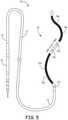
- FIG. 5is a schematic diagram illustrating another example lead 50 constructed in accordance with the principles of the present application.
- Lead 50can include one or more of the structure and/or functionality of lead 10 of FIGS. 1-3 (and vice versa) or lead 40 of FIG. 4 , including the electrode and lead body dimensions, spacings, materials, shapes, orientations, electrical conductor configurations, and the like. Repetitive description of like numbered elements described in other embodiments is omitted for sake of brevity.
- Lead 50includes an undulating portion 52. Undulating portion 52 includes two peaks 24, similar to undulating portion 42 of lead 40, but undulating portion 52 includes a longer peak-to-peak width "w.” Lead 50 also includes three pace/sense electrodes 32 with two of them being disposed between defibrillation electrode segments 28. Unlike the example leads illustrated in FIGS. 1-4 , at least one of the pace/sense electrodes 32 is not substantially aligned or otherwise disposed along the major longitudinal axis "x.”
- FIG. 6is a schematic diagram illustrating another example lead 60 constructed in accordance with the principles of the present application.
- Lead 60can include one or more of the structure and/or functionality of lead 10 of FIGS. 1-3 , lead 40 of FIG. 4 , and/or lead 50 of FIG. 5 (and vice versa), including the electrode and lead body dimensions, spacings, materials, shapes, orientations, electrical conductor configurations, and the like. Repetitive description of like numbered elements described in other embodiments is omitted for sake of brevity.
- Lead 60includes an undulating portion 62.
- Undulating portion 62is substantially similar to undulating portion 22 of lead 10, but undulating portion 62 includes seven peaks 24a-g instead of three peaks.
- Undulating portion 62defines a peak-to-peak distance "d" with similar dimensions described above with respect to FIGS. 1-3 , but the peak-to-peak width "w" may be smaller than the peak-to-peak widths of undulating portions 22, 42, or 52 due to the increased number of peaks 24.
- the defibrillation electrodealso includes more defibrillation electrode segments 28 than the leads 10, 40 and 50.
- the defibrillation electrode segments 28extend along a substantial part of undulating portion 62, e.g., along at least 80% of undulating portion 62.
- the defibrillation electrode segments 28extend along a substantial portion of undulation from the proximal end of undulating portion 62, except for the part of undulating portion 62 that includes the gaps 30 where electrodes 32 are disposed.
- the gaps 30 and electrodes 32bare located along the part of undulating portions 62 that transition from a peak 24 to adjacent peak 24 (at every other transition), instead of at a peak as was the case in lead 10 of FIGS. 1-3 .
- Lead 60also includes three pace/sense electrodes 32a-32c.
- the electrodes 32are disposed along the undulating configuration 62 such that each electrode 32 is substantially aligned or otherwise disposed along the major longitudinal axis "x." Unlike in lead 10, 40 and 50 of FIGS. 1-5 , however, all electrodes 32 are located between adjacent defibrillation electrode segments 28.
- the lead 60may also include one or more electrodes 32 proximal to the most proximal defibrillation electrode segment 28 or distal to the most distal defibrillation electrode segment 28. Electrodes 32 are disposed along the undulating configuration 62 at locations such that the electrodes 32 will be substantially aligned with one another along the anterior median line.
- Defibrillation electrode segments 28 and pace/sense electrodes 32may include the structure and functionality described above with respect to FIGS. 1-3 , including but not limited to the spacing between segments 28 and electrodes 32, the size of segments 28 and 32, electrode and lead body dimensions, spacings, materials, shapes, and the like. Additionally, as described above with respect to FIGS. 1-3 , in some configurations defibrillation electrode segments 28 may each be connected to a common conductor such that a voltage may be applied simultaneously to all the defibrillation electrode segments 28 (and they function as a single polarity) to deliver a defibrillation shock to a patient's heart.
- the defibrillation electrode segments 28may be attached to separate conductors such that each defibrillation electrode segment 28 may apply a voltage independent of the other defibrillation electrode segments 28.
- ICD 9 or lead 60may include one or more switches or other mechanisms to electrically connect the defibrillation electrode segments together to function as a common polarity electrode such that a voltage may be applied simultaneously to all the defibrillation electrode segments 28 in addition to being able to independently apply a voltage.
- FIG. 7is a schematic diagram illustrating another example lead 70 constructed in accordance with the principles of the present application.
- Lead 70can include one or more of the structure and/or functionality of lead 10 of FIGS. 1-3 , lead 40 of FIG. 4 , lead 50 of FIG. 5 and/or lead 60 of FIG. 6 (and vice versa), including the electrode and lead body dimensions, spacings, materials, shapes, orientations, electrical conductor configurations, and the like. Repetitive description of like numbered elements described in other embodiments is omitted for sake of brevity.
- Lead 70includes an undulating portion 72 that is substantially similar to undulating portion 62 of lead 60 of FIG. 6 except that the electrode 32 may be sized to span the distance between two peaks 24 in the undulating configuration 72.
- the electrodes 32may be configured to sense a cardiac depolarization between an adjacent defibrillation electrode segment 28.
- the electrodes 32are configured to deliver pacing pulses to the heart by conductive electrical energy between the electrodes 32 and an adjacent defibrillation electrode segment 28.
- the therapy vectors between a respective electrode 32 and an adjacent defibrillation electrode segment 28may define a substantially rhomboid or diamond configuration to provide for a particular therapy vector. Electrodes 32 may also deliver electrical energy between respective ones of electrodes 32. Repetitive description of like numbered elements described in other embodiments is omitted for the sake of brevity.
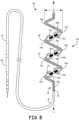
- FIG. 8is a schematic diagram illustrating another example lead 80 constructed in accordance with the principles of the present application.
- Lead 80can include one or more of the structure and/or functionality of lead 10 of FIGS. 1-3 , lead 40 of FIG. 4 , lead 50 of FIG. 5 lead 60 of FIG. 6 , and/or lead 70 of FIG. 7 (and vice versa), including the electrode and lead body dimensions, spacings, materials, shapes, orientations, electrical conductor configurations, and the like. Repetitive description of like numbered elements described in other embodiments is omitted for sake of brevity.
- Lead 80includes an undulating portion 82 that may conform substantially to undulating portion 62 of lead 60 of FIG. 6 and/or undulating portion 72 of lead 70 of FIG. 7 except that two or more electrodes 32 may span the distance between two peaks 24 in the undulating configuration 62.
- the electrodes 32may be disposed in a single gap 30 between adjacent defibrillation electrode segments 28 or each electrode 32 may be disposed in a two gaps 30 and each gap 30 is separated by an electrically insulating section of the lead body 12.
- the electrodes 32may be configured to sense a cardiac depolarization between each other or an adjacent defibrillation electrode segment 28, depending on the polarity of each electrode 32.
- the electrodes 32are configured to deliver pacing pulses to the heart with conductive electrical energy between the electrodes 32 and an adjacent defibrillation electrode segment 28 or between two of the electrodes 32.
- therapy vectorsare shown in FIG. 8 for a configuration in which, for example, electrodes 32a and 32a' have the same polarity and the opposite polarity of an adjacent defibrillation electrode segment 28 to provide for a particular therapy vector.
- electrodes 32a and 32a', and likewise 32b and 32b'and 32c, and 32c'may be coupled to the same or different conductors such that the polarities between each electrode 32 may be the same or different depending on the application.
- each electrode 32a and 32a'may be a portion of the lead body 12 that is electrically insulating.
- the gaps 30may be sized to optimize particular electrical stimulation therapies.
- the gap 30 sizemay range from approximately 8mm-15mm for between a pair of electrodes 32 configured to pace and/or sense a cardiac depolarization.
- the size of the gaps 30 between an electrode 32 and a defibrillation electrode segment 28may be approximately 3-10mm in length or any of the lengths described above with respect to FIGS. 1-3 . Repetitive description of like numbered elements described in other embodiments is omitted for sake of brevity.
- FIG. 9is a schematic diagram illustrating another example lead 90 constructed in accordance with the principles of the present application.
- Lead 90can include one or more of the structure and/or functionality of lead 10 of FIGS. 1-3 , lead 40 of FIG. 4 , lead 50 of FIG. 5 and/or lead 60 of FIG. 6 , lead 70 of FIG. 7 , and/or lead 80 of FIG. 8 (and vice versa), including the electrode and lead body dimensions, spacings, materials, shapes, orientations, electrical conductor configurations, and the like. Repetitive description of like numbered elements described in other embodiments is omitted for sake of brevity.
- Lead 90includes an undulating portion 92 that may conform substantially to undulating portion 62 of lead 60 of FIG. 6 except that electrodes 32 may be directional electrodes positioned to provide a therapy vector aimed at the heart and not skeletal muscle, such that only a portion of the lead body in which the electrodes 32 are disposed contain the electrode 32 and another portion includes the insulating portion of the lead body.
- the electrodes 32would be arranged such that the electrodes are disposed on the posterior side of the lead (e.g., facing the heart) when implanted within the patient.
- the electrodes 32may be configured to sense a cardiac depolarization between an adjacent defibrillation electrode segment 28, between two of electrodes 32, or between electrode(s) 32 and housing electrode.
- the electrodes 32are configured to deliver pacing pulses to the heart by conductive electrical energy between an adjacent defibrillation electrode segment 28, between two of electrodes 32, or between electrode(s) 32 and housing electrode.
- therapy vectorsare shown in FIG. 6 for a configuration in which each electrode 32a, 32b, and 32c are disposed on the superior portion of a lead body 62 section.
- electrodes 32a and 32cmay be facing electrode 32b to provide for particular therapy vectors.
- the arrangement of electrodes 32a, 32b, and 32cmay be such that electrical energy is directed toward the heart and not toward skeletal muscle or non-cardiac tissue to maximize the effectiveness of pacing pulses delivered to the heart. Repetitive description of like numbered elements described in other embodiments is omitted for sake of brevity.
- FIG. 10is a functional block diagram of an example configuration of electronic components of an example ICD 9.
- ICD 9includes a control module 100, sensing module 102, therapy module 104, communication module 108, and memory 110.
- the electronic componentsmay receive power from a power source 106, which may be a rechargeable or non-rechargeable battery.
- ICD 9may include more or fewer electronic components.
- the described modulesmay be implemented together on a common hardware component or separately as discrete but interoperable hardware or software components. Depiction of different features as modules is intended to highlight different functional aspects and does not necessarily imply that such modules must be realized by separate hardware or software components. Rather, functionality associated with one or more modules may be performed by separate hardware or software components, or integrated within common or separate hardware or software components.
- FIG. 10will be described in the context of ICD 9 being coupled to lead 10 for exemplary purposes only. However, ICD 9 may be coupled to other leads, such as lead 40, 50, 60, 70, 80 or 90 described herein, and thus other electrodes
- Sensing module 102is electrically coupled to some or all of electrodes 26 (or separately to segments 28a and/or 28b) and 32 via the conductors of lead 10 and one or more electrical feedthroughs, or to the housing electrode via conductors internal to the housing of ICD 9. Sensing module 102 is configured to obtain signals sensed via one or more combinations of electrodes 26 (or separately to segments 28a and/or 28b) and 32 and the housing electrode of ICD 9 and process the obtained signals.
- sensing module 102may be analog components, digital components or a combination thereof.
- Sensing module 102may, for example, include one or more sense amplifiers, filters, rectifiers, threshold detectors, analog-to-digital converters (ADCs) or the like.
- Sensing module 102may convert the sensed signals to digital form and provide the digital signals to control module 100 for processing or analysis.
- sensing module 102may amplify signals from the sensing electrodes and convert the amplified signals to multi-bit digital signals by an ADC.
- Sensing module 102may also compare processed signals to a threshold to detect the existence of atrial or ventricular depolarizations (e.g., P- or R-waves) and indicate the existence of the atrial depolarization (e.g., P-waves) or ventricular depolarizations (e.g., R-waves) to control module 100.
- a thresholdto detect the existence of atrial or ventricular depolarizations (e.g., P- or R-waves) and indicate the existence of the atrial depolarization (e.g., P-waves) or ventricular depolarizations (e.g., R-waves) to control module 100.
- Control module 100may process the signals from sensing module 102 to monitor electrical activity of the heart of the patient. Control module 100 may store signals obtained by sensing module 102 as well as any generated EGM waveforms, marker channel data or other data derived based on the sensed signals in memory 110. Control module 100 may analyze the EGM waveforms and/or marker channel data to detect cardiac events (e.g., tachycardia). In response to detecting the cardiac event, control module 100 may control therapy module 104 to deliver the desired therapy to treat the cardiac event, e.g., defibrillation shock, cardioversion shock, ATP, post-shock pacing, or bradycardia pacing.
- cardiac eventse.g., tachycardia
- control therapy module 104may deliver the desired therapy to treat the cardiac event, e.g., defibrillation shock, cardioversion shock, ATP, post-shock pacing, or bradycardia pacing.
- Therapy module 104is configured to generate and deliver electrical stimulation therapy to the heart.
- Therapy module 104may include one or more pulse generators, capacitors, and/or other components capable of generating and/or storing energy to deliver as pacing therapy, defibrillation therapy, cardioversion therapy, cardiac resynchronization therapy, other therapy or a combination of therapies.
- therapy module 104may include a first set of components configured to provide pacing therapy and a second set of components configured to provide defibrillation therapy.
- therapy module 104may utilize the same set of components to provide both pacing and defibrillation therapy.
- therapy module 104may share some of the defibrillation and pacing therapy components while using other components solely for defibrillation or pacing.
- Control module 100may control therapy module 104 to deliver the generated therapy to the heart via one or more combinations of electrodes 26 (or separately to segments 28a and/or 28b) and 32 of lead 10 and the housing electrode of ICD 9 according to one or more therapy programs, which may be stored in memory 110. In instances in which control module 100 is coupled to a different lead, e.g., lead 40, 50, 60, 70, 80, or 90, other electrodes may be utilized. Control module 100 controls therapy module 104 to generate electrical stimulation therapy with the amplitudes, pulse widths, timing, frequencies, electrode combinations or electrode configurations specified by a selected therapy program.
- Therapy module 104may include a switch module to select which of the available electrodes are used to deliver the therapy.
- the switch modulemay include a switch array, switch matrix, multiplexer, or any other type of switching device suitable to selectively couple electrodes to therapy module 104.
- Control module 100may select the electrodes to function as therapy electrodes, or the therapy vector, via the switch module within therapy module 104. In instances in which defibrillation segments 28a and 28b are each coupled to separate conductors, control module 100 may be configured to selectively couple therapy module 104 to either one of segments 28a and 28b individually or couple to both of the segments 28a and 28b concurrently. In some instances, the same switch module may be used by both therapy module 104 and sensing module 102. In other instances, each of sensing module 102 and therapy module 104 may have separate switch modules.
- therapy module 104may deliver pacing (e.g., ATP or post-shock pacing) using an electrode vector that includes one or both defibrillation electrode segments 28a and 28b.
- pacing therapye.g., ATP, post-shock pacing, and/or bradycardia pacing provided via electrodes 32 and/or defibrillation electrode segments 28a and 28b of lead 10.
- therapy module 104may deliver pacing (e.g., ATP or post-shock pacing) using an electrode vector that includes one or both defibrillation electrode segments 28a and 28b.
- the electrode vector used for pacingmay be segment 28a as an anode (or cathode) and one of electrodes 28b, 32 or the housing of ICD 9 as the cathode (or anode) or segment 28b as an anode (or cathode) and one of electrodes 28b, 32 or the housing of ICD 9as the cathode (or anode).
- therapy module 104may generate and deliver a cardioversion/defibrillation shock (or shocks) using one or both of electrode segments 28 concurrently as a cathode and the housing electrode of ICD 9 as an anode.
- Control module 100controls therapy module 104 to generate and deliver pacing pulses with any of a number of shapes, amplitudes, pulse widths, or other characteristic to capture the heart.
- the pacing pulsesmay be monophasic, biphasic, or multiphasic (e.g., more than two phases).
- the pacing thresholds of the heart when delivering pacing pulses from the substernal spacemay depend upon a number of factors, including location, type, size, orientation, and/or spacing of electrodes 32 and/or electrode segments 28, location of ICD 9 relative to electrodes 32 and/or electrode segments 28, physical abnormalities of the heart (e.g., pericardial adhesions or myocardial infarctions), or other factor(s).
- therapy module 104may be configured to generate and deliver pacing pulses having larger amplitudes and/or pulse widths than conventionally required to obtain capture via leads implanted within the heart (e.g., transvenous leads) or leads attached directly to the heart.
- therapy module 104may generate and deliver pacing pulses having amplitudes of less than or equal to 8 volts and pulse widths between 0.5 - 3.0 milliseconds and, in some instances up to 4 milliseconds.
- therapy module 104may generate and deliver pacing pulses having amplitudes of between 5 and 10 volts and pulse widths between approximately 3.0 milliseconds and 10.0 milliseconds. In another example, therapy module 104 may generate and deliver pacing pulses having pulse widths between approximately 2.0 milliseconds and 8.0 milliseconds. In a further example, therapy module 104 may generate and deliver pacing pulses having pulse widths between approximately 0.5 milliseconds and 20.0 milliseconds. In another example, therapy module 104 may generate and deliver pacing pulses having pulse widths between approximately 1.5 milliseconds and 20.0 milliseconds.
- Pacing pulses having longer pulse durations than conventional transvenous pacing pulsesmay result in lower energy consumption.
- therapy module 104may be configured to generate and deliver pacing pulses having pulse widths or durations of greater than two (2) milliseconds.
- therapy module 104may be configured to generate and deliver pacing pulses having pulse widths or durations of between greater than two (2) milliseconds and less than or equal to three (3) milliseconds.
- therapy module 104may be configured to generate and deliver pacing pulses having pulse widths or durations of greater than or equal to three (3) milliseconds.
- therapy module 104may be configured to generate and deliver pacing pulses having pulse widths or durations of greater than or equal to four (4) milliseconds. In another example, therapy module 104 may be configured to generate and deliver pacing pulses having pulse widths or durations of greater than or equal to five (5) milliseconds. In another example, therapy module 104 may be configured to generate and deliver pacing pulses having pulse widths or durations of greater than or equal to ten (10) milliseconds. In a further example, therapy module 104 may be configured to generate and deliver pacing pulses having pulse widths between approximately 3-10 milliseconds.
- therapy module 104may be configured to generate and deliver pacing pulses having pulse widths between approximately 4-10 milliseconds. In a further example, therapy module 104 may be configured to generate and deliver pacing pulses having pulse widths or durations of greater than or equal to fifteen (15) milliseconds. In yet another example, therapy module 104 may be configured to generate and deliver pacing pulses having pulse widths or durations of greater than or equal to twenty (20) milliseconds.
- ICD 9may be configured to deliver pacing pulses having pulse amplitudes less than or equal to twenty (20) volts, deliver pacing pulses having pulse amplitudes less than or equal to ten (10) volts, deliver pacing pulses having pulse amplitudes less than or equal to five (5) volts, deliver pacing pulses having pulse amplitudes less than or equal to two and one-half (2.5) volts, deliver pacing pulses having pulse amplitudes less than or equal to one (1) volt.
- the pacing pulse amplitudesmay be greater than 20 volts. Typically the lower amplitudes require longer pacing widths as illustrated in the experimental results. Reducing the amplitude of pacing pulses delivered by ICD 9 reduces the likelihood of extra-cardiac stimulation and lower consumed energy of power source 106.
- pacing amplitudes and pulse widthsmay vary, e.g., be increased given the further distances from heart and the various anatomical features via which the energy must penetrate.
- control module 100controls therapy module 104 to generate cardioversion or defibrillation shocks having any of a number of waveform properties, including leading-edge voltage, tilt, delivered energy, pulse phases, and the like.
- Therapy module 104may, for instance, generate monophasic, biphasic or multiphasic waveforms. Additionally, therapy module 104 may generate cardioversion or defibrillation waveforms having different amounts of energy.
- delivering cardioversion or defibrillation shocks from the substernal spacemay reduce the amount of energy that needs to be delivered to defibrillate the heart.
- therapy module 104may generate and deliver cardioversion or defibrillation shocks having energies of less than 65 J, less than 100 J, between 40-50 J, between 35-100 J, and in some instances less than 35 J.
- ICD 9may generate and deliver cardioversion or defibrillation shocks having energies around 65-80 J.
- Therapy module 104may also generate defibrillation waveforms having different tilts.
- therapy module 104may use a 65/65 tilt, a 50/50 tilt, or other combinations of tilt.
- the tilts on each phase of the biphasic or multiphasic waveformsmay be the same in some instances, e.g., 65/65 tilt. However, in other instances, the tilts on each phase of the biphasic or multiphasic waveforms may be different, e.g., 65 tilt on the first phase and 55 tilt on the second phase.
- example delivered energies, leading-edge voltages, phases, tilts, and the likeare provided for example purposes only and should not be considered as limiting of the types of waveform properties that may be utilized to provide substernal defibrillation via defibrillation electrode segment(s) 28.
- Communication module 108includes any suitable hardware, firmware, software or any combination thereof for communicating with another device, such as a clinician programmer, a patient monitoring device, or the like.
- communication module 108may include appropriate modulation, demodulation, frequency conversion, filtering, and amplifier components for transmission and reception of data with the aid of antenna 112.
- Antenna 112may be located within connector block of ICD 9 or within housing ICD 9.
- the various modules of ICD 9may include any one or more processors, controllers, digital signal processors (DSPs), application specific integrated circuits (ASICs), field-programmable gate arrays (FPGAs), or equivalent discrete or integrated circuitry, including analog circuitry, digital circuitry, or logic circuitry.
- Memory 110may include computer-readable instructions that, when executed by control module 100 or other component of ICD 9, cause one or more components of ICD 9 to perform various functions attributed to those components in this disclosure.
- Memory 110may include any volatile, non-volatile, magnetic, optical, or electrical media, such as a random access memory (RAM), read-only memory (ROM), non-volatile RAM (NVRAM), static non-volatile RAM (SRAM), electrically-erasable programmable ROM (EEPROM), flash memory, or any other non-transitory computer-readable storage media.
- RAMrandom access memory
- ROMread-only memory
- NVRAMnon-volatile RAM
- SRAMstatic non-volatile RAM
- EEPROMelectrically-erasable programmable ROM
- flash memoryor any other non-transitory computer-readable storage media.
- the leads and systems described hereinmay be used at least partially within the substernal space, e.g., within anterior mediastinum of patient, to provide an extravascular ICD system.
- An implantere.g., physician
- implantermay create an incision near the center of the torso of the patient, e.g., and introduce the implant tool into the substernal location via the incision.
- the implant toolis advanced from the incision superior along the posterior of the sternum in the substernal location.
- the distal end of lead 10(or other lead described herein, e.g., leads 40, 50, 60, 70, 80, or 90) is introduced into tunnel via implant tool (e.g., via a sheath). As the distal end of lead 10 is advanced through the substernal tunnel, the distal end of lead 10 is relatively straight.
- the pre-formed or shaped undulating portion 22is flexible enough to be straightened out while routing the lead 10 through a sheath or other lumen or channel of the implant tool.
- the implant toolis withdrawn toward the incision and removed from the body of the patient while leaving lead 10 in place along the substernal path.
- the distal end of lead 10takes on its pre-formed undulating configuration 22.
- the undulating configuration 22pushes electrodes 32a and 32b toward the left side of sternum compared to electrodes 28a and 28b.
- the implantermay align the electrodes 32a and 32b along the anterior median line (or midsternal line) or the left sternal lines (or left lateral sternal line).
Landscapes
- Health & Medical Sciences (AREA)
- Cardiology (AREA)
- Life Sciences & Earth Sciences (AREA)
- Heart & Thoracic Surgery (AREA)
- Public Health (AREA)
- Engineering & Computer Science (AREA)
- Biomedical Technology (AREA)
- Veterinary Medicine (AREA)
- Animal Behavior & Ethology (AREA)
- General Health & Medical Sciences (AREA)
- Nuclear Medicine, Radiotherapy & Molecular Imaging (AREA)
- Radiology & Medical Imaging (AREA)
- Physiology (AREA)
- Physics & Mathematics (AREA)
- Biophysics (AREA)
- Pathology (AREA)
- Medical Informatics (AREA)
- Molecular Biology (AREA)
- Surgery (AREA)
- Vascular Medicine (AREA)
- Electrotherapy Devices (AREA)
Description
- The present application relates to electrical stimulation leads and, more particularly, electrical stimulation leads having an undulating configuration for improved defibrillation, sensing, and/or pacing capabilities for use in extracardiovascular applications (e.g., subcutaneous or substernal applications).
- Malignant tachyarrhythmia, for example, ventricular fibrillation, is an uncoordinated contraction of the cardiac muscle of the ventricles in the heart, and is the most commonly identified arrhythmia in cardiac arrest patients. If this arrhythmia continues for more than a few seconds, it may result in cardiogenic shock and cessation of effective blood circulation. As a consequence, sudden cardiac death (SCD) may result in a matter of minutes.
- In patients with a high risk of ventricular fibrillation, the use of an implantable cardioverter defibrillator (ICD) system has been shown to be beneficial at preventing SCD. An ICD system includes an ICD that is a battery powered electrical shock device, that may include an electrical housing electrode (sometimes referred to as a can electrode), that is coupled to one or more electrical lead wires placed within the heart. If an arrhythmia is sensed, the ICD may send a pulse via the electrical lead wires to shock the heart and restore its normal rhythm. Owing to the inherent surgical risks in attaching and replacing electrical leads directly within or on the heart, subcutaneous ICD systems have been devised to provide shocks to the heart without placing electrical lead wires within the heart or attaching electrical wires directly to the heart.
- Electrical leads being utilized in subcutaneous systems typically include linear or curvilinear arrays of electrodes positioned on the lead body. Thus, the delivery of electrical stimulation therapy to the heart with current lead designs provides limited therapy vectors depending on the shape of the lead body, for which the electrical energy may impact the heart.
US 2008/046059 A1 discloses a lead including a heat fused or formed lead body.- The present invention provides an extravascular implantable medical electrical lead according to
claim 1. Further aspects and preferred embodiments are defined in the dependent claims. Aspects, embodiments, examples, and methods of the present disclosure that do not fall within the scope of the appended claims do not form part of the invention and are merely provided for illustrative purposes. - This disclosure describes an implantable medical electrical lead and an ICD system utilizing the lead. The lead includes a lead body defining a proximal end and a distal portion, wherein at least a part of the distal portion of the lead body defines an undulating configuration. The lead includes a defibrillation electrode that includes a plurality of defibrillation electrode segments disposed along the undulating configuration spaced apart from one another by a distance. The lead also includes at least one electrode disposed between adjacent sections of the plurality of defibrillation sections. The at least one electrode is configured to deliver a pacing pulse to the heart and/or sense cardiac electrical activity of the heart.
- In some instances, the plurality of defibrillation electrode segments are disposed along at least 80% of undulating configuration. In other instances, the plurality of defibrillation electrode segments are disposed along at least 90% of undulating configuration. The undulating configuration may include a plurality of peaks with a first portion of the plurality of peaks extending in a first direction away from a major longitudinal axis of the lead and a second portion of the plurality of peaks extending in a second, opposite direction away from the major longitudinal axis of the lead. The plurality of defibrillation electrode segments may, in some examples, be disposed along the first portion of the plurality of peaks and the at least one electrode may be disposed on the second portion of the plurality of peaks. In another example, the plurality of defibrillation electrode segments are disposed along at least one of the first and second portions of peaks and the at least one electrode is disposed along a segment of the undulating portion between peaks.
- This application also provides an extravascular implantable cardioverter-defibrillator (ICD) system comprising an extravascular electrical stimulation lead and an ICD coupled to the extravascular electrical stimulation lead. The electrical stimulation lead includes a lead body defining a proximal end and a distal portion, wherein at least a part of the distal portion of the lead body defines an undulating configuration. The lead includes a defibrillation electrode that includes at least a first defibrillation electrode segment and a second defibrillation electrode segment disposed along the undulating configuration spaced apart from one another by a distance. The lead also includes at least one electrode disposed between the first and second defibrillation segments, the at least one electrode configured to, at least one of, deliver a pacing pulse to the heart and sense cardiac electrical activity of the heart.
- This application also provides a method for implanting an extravascular electrical stimulation lead within a substernal location of a patient. The method includes creating an incision near a center of the torso of the patient, introducing an implant tool into the substernal location via the incision, and advancing the implant tool within the substernal location from the incision superior along a posterior of a sternum to form a substernal path. The method further includes introducing a distal portion of the lead into the substernal location. The lead includes a lead body defining a proximal end and the distal portion, wherein at least a part of the distal portion of the lead body defines a pre-formed undulating configuration, a defibrillation electrode that includes a plurality of defibrillation electrode segments disposed along the undulating configuration spaced apart from one another by a distance, and at least one electrode disposed between adjacent segments of the plurality of defibrillation segments, the at least one electrode configured to, at least one of, deliver a pacing pulse to the heart and sense cardiac electrical activity of the heart. The method includes advancing the distal portion of the lead through the substernal path, wherein the undulating configuration of the lead is in a relatively straight configuration when being advanced through the substernal path, and withdrawing the implant tool toward the incision to remove the implant tool from the body while leaving the lead in place along the substernal path. The distal portion of the lead takes its pre-formed undulating configuration within the substernal location as it exist the implant tool. The at least one electrode is disposed on the undulating configuration such that that undulating configuration pushes the at least one electrodes toward the left side of sternum compared to defibrillation electrode segments.
FIG. 1A is a front view of a patient implanted with the extracardiovascular ICD system implanted intra-thoracically.FIG. 1B is a side view of the patient implanted with the extracardiovascular ICD system implanted intra-thoracically.FIG. 1C is a transverse view of the patient implanted with the extracardiovascular ICD system implanted intra-thoracically.FIG. 2 is a front view of a patient implanted with the extracardiovascular ICD system implanted extra-thoracically.FIG. 3A is a schematic diagram illustrating an example lead constructed in accordance with the principles of the present application.FIG. 3B is a schematic diagram illustrating an side view of the distal portion of the example lead ofFIG. 3A .FIG. 4 is a schematic diagram illustrating another example lead constructed in accordance with the principles of the present application.FIG. 5 is a schematic diagram illustrating a further example lead constructed in accordance with the principles of the present application.FIG. 6 is a schematic diagram illustrating another example lead constructed in accordance with the principles of the present application.FIG. 7 is a schematic diagram illustrating another example lead constructed in accordance with the principles of the present application.FIG. 8 is a schematic diagram illustrating another example lead constructed in accordance with the principles of the present application.FIG. 9 is a schematic diagram illustrating another example lead constructed in accordance with the principles of the present application.FIG. 10 is a functional block diagram of an example configuration of electronic components of an example ICD, such as the ICD of the system inFIGS. 1A ,1C , and2 .- As used herein, relational terms, such as "first" and "second," "over" and "under," "front" and "rear," and the like, may be used solely to distinguish one entity or element from another entity or element without necessarily requiring or implying any physical or logical relationship or order between such entities or elements.
- Referring now to the drawings in which like reference designators refer to like elements, there is shown in
FIGS. 1A-C andFIG. 2 are conceptual diagrams illustrating various views of an exemplary extracardiovascular implantable cardioverter-defibrillator (ICD) system 8. ICD system 8 includes an ICD 9 connected to a medicalelectrical lead 10 constructed in accordance with the principles of the present application.FIG. 1A is a front view of a patient implanted with the extracardiovascular ICD system 8.FIG. 1B is a side view of the patient implanted with the extracardiovascular ICD system 8.FIG. 1C is a transverse view of the patient implanted with the extracardiovascular ICD system 8. - The ICD 9 may include a housing that forms a hermetic seal that protects components of the ICD 9. The housing of the ICD 9 may be formed of a conductive material, such as titanium or titanium alloy, which may function as a housing electrode (sometimes referred to as a can electrode). In other embodiments, the ICD 9 may be formed to have or may include one or more electrodes on the outermost portion of the housing. The ICD 9 may also include a connector assembly (also referred to as a connector block or header) that includes electrical feedthroughs through which electrical connections are made between conductors of
lead 10 and electronic components included within the housing of the ICD 9. As will be described in further detail herein, housing may house one or more processors, memories, transmitters, receivers, sensors, sensing circuitry, therapy circuitry, power sources and other appropriate components. The housing is configured to be implanted in a patient, such as the patient. - ICD 9 is implanted extra-thoracically on the left side of the patient, e.g., under the skin and outside the ribcage (subcutaneously or submuscularly). ICD 9 may, in some instances, be implanted between the left posterior axillary line and the left anterior axillary line of the patient. ICD 9 may, however, be implanted at other extra-thoracic locations on the patient as described later.
FIG. 3A and3B are schematic diagrams illustrating various views oflead 10 in further detail. Thelead 10 may include anelongated lead body 12 sized to be implanted in an extracardiovascular location proximate the heart, e.g., intra-thoracically (as illustrated inFIGS. 1A-C ) or extra-thoracically (as illustrated inFIG. 2 ). For example, thelead 10 may extend extra-thoracically under the skin and outside the ribcage (e.g., subcutaneously or submuscularly) from ICD 9 toward the center of the torso of the patient, for example, toward the xiphoid process of the patient. At a position proximate xiphoid process, thelead body 12 may bend or otherwise turn and extend superiorly. In the example illustrated inFIGS. 1A-C , thelead body 12 extends superiorly intra-thoracically underneath the sternum, in a direction substantially parallel to the sternum. In one example, thedistal portion 16 oflead 10 may reside in a substernal location such thatdistal portion 16 oflead 10 extends superior along the posterior side of the sternum substantially within theanterior mediastinum 36.Anterior mediastinum 36 may be viewed as being bounded laterally bypleurae 39, posteriorly bypericardium 38, and anteriorly by thesternum 22. In some instances, the anterior wall ofanterior mediastinum 36 may also be formed by the transversus thoracis and one or more costal cartilages.Anterior mediastinum 36 includes a quantity of loose connective tissue (such as areolar tissue), adipose tissue, some lymph vessels, lymph glands, substernal musculature (e.g., transverse thoracic muscle), the thymus gland, branches of the internal thoracic artery, and the internal thoracic vein. In another example, e.g., illustrated inFIG. 2 , thelead body 12 may extend superiorly extra-thoracically (instead of intra-thoracically), e.g., either subcutaneously or submuscularly above the ribcage/sternum. Thelead 10 may be implanted at other locations, such as over the sternum, offset to the right of the sternum, angled lateral from the proximal or distal end of the sternum, or the like.- The
lead body 12 may have a generally tubular or cylindrical shape and may define a diameter of approximately 3-9 French (Fr), however, lead bodies of less than 3 Fr and more than 9 Fr may also be utilized. In another configuration, thelead body 12 may have a flat, ribbon, or paddle shape with solid, woven filament, or metal mesh structure, along at least a portion of the length of thelead body 12. In such an example, the width across thelead body 12 may be between 1-3.5 mm. Other lead body designs may be used without departing from the scope of this application. - The
lead body 12 oflead 10 may be formed from a non-conductive material, including silicone, polyurethane, fluoropolymers, mixtures thereof, and other appropriate materials, and shaped to form one or more lumens (not shown), however, the techniques are not limited to such constructions. Thedistal portion 16 may be fabricated to be biased in a desired configuration, or alternatively, may be manipulated by the user into the desired configuration. For example, thedistal portion 16 may be composed of a malleable material such that the user can manipulate the distal portion into a desired configuration where it remains until manipulated to a different configuration. - The
lead body 12 may include aproximal end 14 and adistal portion 16 which include an electricalstimulation therapy portion 18 configured to deliver electrical energy to the heart or sense electrical energy of the heart. Thedistal portion 16 may be anchored to a desired positioned within the patient, for example, substernally or subcutaneously by, for example, suturing thedistal portion 16 to the patient's musculature, tissue, or bone at the xiphoid process entry site. Alternatively, thedistal portion 16 may be anchored to the patient or through the use of rigid tines, prongs, barbs, clips, screws, and/or other projecting elements or flanges, disks, pliant tines, flaps, porous structures such as a mesh-like element and metallic or non-metallic scafolds that facilitate tissue growth for engagement, bio-adhesive surfaces, and/or any other non-piercing elements. - The
lead body 12 may define a substantiallylinear portion 20 as it curves or bends near the xiphoid process and extends superiorly. As shown inFIGS. 1-3 , at least a part of thedistal portion 16 may define an undulatingconfiguration 22 distal to the substantiallylinear portion 20. In particular, thedistal portion 16 may define an undulating pattern, e.g., (zig-zag, meandering, sinusoidal, serpentine, or other pattern) as it extends toward the distal end of thedistal portion 16. In other configurations, thelead body 12 may not have a substantiallylinear portion 20 as it extends superiorily, but instead the undulating configuration may begin immediately after the bend. - The undulating
configuration 22 may include a plurality of peaks 24 along the length of thedistal portion 16. In an exemplary configuration, the undulatingconfiguration 22 oflead 10 includes threepeaks configuration 22 may include any number of peaks 24. For example, the number of peaks 24 may be fewer or greater than three depending on the frequency of theundulation configuration 22. For example, a higherfrequency undulating configuration 22 may include more peaks 24 (e.g., as illustrated in the examples illustrated inFIGS. 6-9 ) while a lowerfrequency undulating configuration 22 may include fewer peaks 24 (e.g., as illustrated in the examples ofFIGS. 4 and5 ). - The undulating
configuration 22 may further define a peak-to-peak distance "d," (shown inFIG. 3 ), which may be variable or constant along the length of the undulatingconfiguration 22. In the configuration illustrated inFIGS. 1-3 , the undulatingconfiguration 22 defines a substantially sinusoidal configuration, with a constant peak-to-peak distance "d" of approximately 2.0-5.0 cm. The undulatingconfiguration 22 may also define a peak-to-peak width "w," (shown inFIG. 3 ), which may also be variable or constant along the length of the undulatingconfiguration 22. In the configuration illustrated inFIGS. 1-3 , the undulatingconfiguration 22 defines a substantially sinusoidal shape, with a constant peak-to-peak width "w" of approximately 0.5-2.0 cm. However, in other instances, the undulatingconfiguration 22 may define other shapes and/or patterns, e.g., S-shapes, wave shapes, or the like. - The
distal portion 16 includes adefibrillation electrode 26 configured to deliver a cardioversion/defibrillation shock to the patient's heart. Thedefibrillation electrode 26 may include a plurality of sections orsegments 28 spaced a distance apart from each other along the length of thedistal portion 16. Thedefibrillation electrode segments 28 may be a disposed around or within thelead body 12 of thedistal portion 16, or alternatively, may be embedded within the wall of thelead body 12. In one configuration, thedefibrillation electrode segments 28 may be a coil electrode formed by a conductor. The conductor may be formed of one or more conductive polymers, ceramics, metal-polymer composites, semiconductors, metals or metal alloys, including but not limited to, one of or a combination of the platinum, tantalum, titanium, niobium, zirconium, ruthenium, indium, gold, palladium, iron, zinc, silver, nickel, aluminum, molybdenum, stainless steel, MP35N, carbon, copper, polyaniline, polypyrrole and other polymers. In another configuration, each of thedefibrillation electrodes segments 28 may be a flat ribbon electrode, a paddle electrode, a braided or woven electrode, a mesh electrode, a directional electrode, a patch electrode or another type of electrode configured to deliver a cardioversion/defibrillation shock to the patient's heart. - In the example illustrated in
FIGS. 1-3 ,defibrillation electrode 26 includes two sections orsegments defibrillation electrode segments 28 extend along a substantial part of undulatingportion 22, e.g., along at least 80% of undulatingportion 22. Thedefibrillation electrode segments 28 may extend along more or less than 80% of the undulatingconfiguration 22. As another example, thedefibrillation electrode segments 28 may extend along at least 90% of the undulatingconfiguration 22. Thedefibrillation electrode segment 28a extends along a substantial portion of undulation from the proximal end of undulatingportion 22 to peak 24b (e.g., along a substantial portion of the first "wave" associated withpeak 24a) and thedefibrillation electrode segment 28b extends along a substantial portion of undulation frompeak 24b to distal end of undulating portion 22 (e.g., along a substantial portion of the second "wave" associated with peak 24c). In the example illustrated inFIGS. 1-3 , the only part of undulatingportion 22 thatdefibrillation electrode 26 is not disposed on is thegap 30 onpeak 24b whereelectrode 32b is disposed. - In one configuration, the
defibrillation electrode segments 28 are spaced approximately 0.25-4.5 cm, and in some instances between 1-3 cm apart from each other. In another configuration, thedefibrillation electrode segments 28 are spaced approximately 0.25-1.5 cm apart from each other. In a further configuration, thedefibrillation electrode segments 28 are spaced approximately 1.5-4.5 cm apart from each other. In the configuration shown inFIGS. 1-3 , thedefibrillation electrode segments 28 span a substantial part of thedistal portion 16. Each of thedefibrillation electrode segments 28 may be between approximately 1-10 cm in length and, more preferably, between 2-6 cm in length and, even more preferably, between 3-5 cm in length. However, lengths of greater than 10 cm and less than 1 cm may be utilized without departing from the scope of this disclosure. A total length of defibrillation electrode 26 (e.g., length of the twosegments 28 combined) may vary depending on a number of variables. Thedefibrillation electrode 26 may, in one example, have a total length of between approximately 5-10 cm. However, the defibrillation electrode segments 24 may have a total length less than 5 cm and greater than 10 cm in other embodiments. In some instances,defibrillation segments 28 may be approximately the same length or, alternatively, different lengths. - The
defibrillation electrode segments 28 may be electrically connected to one or more conductors, which may be disposed in the body wall of thelead body 12 or may alternatively be disposed in one or more insulated lumens (not shown) defined by thelead body 12. In an exemplary configuration, each of thedefibrillation electrode segments 28 is connected to a common conductor such that a voltage may be applied simultaneously to all thedefibrillation electrode segments 28 to deliver a defibrillation shock to a patient's heart. In other configurations, thedefibrillation electrode segments 28 may be attached to separate conductors such that eachdefibrillation electrode segment 28 may apply a voltage independent of the otherdefibrillation electrode segments 28. In this case, ICD 9 or lead 10 may include one or more switches or other mechanisms to electrically connect the defibrillation electrode segments together to function as a common polarity electrode such that a voltage may be applied simultaneously to all thedefibrillation electrode segments 28 in addition to being able to independently apply a voltage. - The
distal portion 16 may define one ormore gaps 30 betweenadjacent defibrillation segments 28. Thegaps 30 may define any length. In instances in which more than twodefibrillation segments 28 exist, eachgap 30 may define the same or substantially the same length as everyother gap 30 or may define a different length thanother gap 30 in the distal portion. In the example ofFIGS. 3 , asingle gap 30 exists betweendefibrillation electrode segments 28. One or more electrodes 32 may be disposed within therespective gap 30. In the configuration shown inFIG. 1 , asingle electrode 32b is disposed within thegap 30. However, in other examples, more than one electrode 32 may exist within the gap 30 (e.g., as illustrated in the example ofFIGS. 4 and8 ). In the configuration shown inFIG. 1 , anotherelectrode 32a is located proximal todefibrillation electrode segment 28a. In other configurations, additional electrodes 32 may be disposed along thedistal portion 16 oflead 10, e.g., distal todefibrillation electrode segment 28b and/or proximal toelectrode segment 28a. - In one example, the distance between the closest
defibrillation electrode segment 28 and electrodes 32 is greater than or equal to 2 mm and less than or equal to 1.5 cm. In another example, electrodes 32 may be spaced apart from the closest one ofdefibrillation electrode segments 28 by greater than or equal to 5 mm and less than or equal to 1 cm. In a further example, electrodes 32 may be spaced apart from the closest one ofdefibrillation electrode segments 28 by greater than or equal to 6 mm and less than or equal to 8 mm - The
electrodes adjacent defibrillation segment 28 by including an electrically insulating layer of material between the electrodes 32 and theadjacent defibrillation segments 28. Each electrode 32 may have its own separate conductor such that a voltage may be applied to each electrode independently from another electrode 32 in thedistal portion 16. In other configurations, each electrode 32 may be coupled to a common conductor such that each electrode 32 may apply a voltage simultaneously. - In the configurations shown in
FIGS. 1-3 , each electrode 32 is substantially aligned along a major longitudinal axis ("x"). In one example, the major longitudinal axis is defined by a portion of theelongate body 12, e.g., the substantiallylinear portion 20. In another example, the major longitudinal axis is defined relative to the body of the patient, e.g., along the anterior median line (or midsternal line), one of the sternal lines (or lateral sternal lines), left parasternal line, or other line. Theelectrodes configuration 22 such that eachelectrode electrode electrode distal portion 16 disposed between, proximal to, or distal to thedefibrillation electrode segments 28, as described in other embodiments herein. In the example illustrated inFIGS. 1-3 , the electrodes 32 are disposed along the undulatingconfiguration 22 at locations that will be closer to the heart of the patient than defibrillation electrode segments 28 (e.g., atpeak 24b that is toward the left side of the sternum). As illustrated inFIG. 1A , for example, the electrodes 32 are substantially aligned with one another along the left sternal line. Thedefibrillation electrode segments 28 are disposed along thepeaks - As illustrated in longitudinal side view of
distal portion 16 ofFIG. 3B , the pace/sense electrodes 32 and thedefibrillation electrode segments 28 may further be disposed in a common plane when thedistal portion 16 is implanted extracardiovasculalry. In particular, the undulatingconfiguration 22 is substantially disposed in a plane defined by the longitudinal axis "x" and a horizontal axis ("y"), referred to herein as the horizontal plane (e.g., the x-y plane). In the example illustrated inFIG. 3B , eachdefibrillation electrode segment 28 and each electrode 32 is at least partially disposed in the horizontal plane. Optionally, in other configurations, the undulatingconfiguration 22 may not be substantially disposed in the horizontal plane. Instead, the electricalstimulation therapy portion 18 may be curved such that one or more thedefibrillation electrode segments 28 or pace/sense electrodes 32 may be pressed inward toward the heart. For example, the electricalstimulation therapy portion 18 may define a concavity or a curvature to place the one or more of thedefibrillation electrode segments 28 or the pace/sense electrodes 32 close to the heart. In such case, the undulatingportion 22 may be viewed as being a 3-dimensional serpentine shape in which some of the peaks or portions of the peaks 24 extend in the z-direction, perpendicular to the horizontal plane and toward the heart. - The
proximal end 14 of thelead body 12 may include one ormore connectors 34 to electrically couple the lead 10 to the implantable cardioverter-defibrillator (ICD) 9 subcutaneously implanted within the patient, for example, under the left armpit of the patient. The ICD 9 may include ahousing 38 that forms a hermetic seal which protects the components of ICD 9. Thehousing 38 of ICD 9 may be formed of a conductive material, such as titanium or titanium alloy, which may function as a housing electrode for a particular therapy vector as illustrated by the arrows inFIG. 1 between thehousing 38 and thedistal portion 16. TheICD 36 may also include a connector assembly that includes electrical feedthroughs through which electrical connections are made between the one ormore connectors 34 oflead 10 and the electronic components included within thehousing 38. Thehousing 38 may house one or more processors, memories, transmitters, receivers, sensors, sensing circuitry, therapy circuitry, power sources (capacitors and batteries) and/or other appropriate components. The components of ICD 9 may generate and deliver electrical stimulation therapy such as anti-tachycardia pacing, cardioversion or defibrillation shocks, post-shock pacing, bradycardia pacing, or other electrical stimulation. - The particular configuration of the undulating
configuration 22 and the inclusion of the electrodes 32 betweendefibrillation electrode segments 28 provides a number of therapy vectors for the delivery of electrical stimulation therapy to the heart. For example, as shown inFIGS. 1-3 , at least a portion of thedefibrillation electrode 26 and one of the electrodes 32 may be disposed over the right ventricle, or any chamber of the heart, such that pacing pulses and defibrillation shocks may be delivered to the heart from thetherapy portion 18. Thehousing 38 may be charged with or function as a polarity different than the polarity of the one or moredefibrillation electrode segments 28 and/or electrodes 32 such that electrical energy may be delivered between thehousing 38 and the defibrillation electrode segment(s) 28 and/or electrode(s) 32 to the heart. Eachdefibrillation electrode segment 28 may have the same polarity as every otherdefibrillation electrode segment 28 when a voltage is applied to it such that a defibrillation shock may be delivered from the entirety of thedefibrillation electrode 26. In embodiments in whichdefibrillation electrode segments 28 are electrically connected to a common conductor withinlead body 12, this is the only configuration ofdefibrillation electrode segments 28. However, in other embodiments,defibrillation electrode segments 28 may be coupled to separate conductors withinlead body 12 and may therefore each have different polarities such that electrical energy may flow between defibrillation electrode segments 28 (or between one ofdefibrillation electrode segments 28 and one or pace/sense electrodes 32 or the housing electrode) to provide pacing therapy and/or to sense cardiac depolarizations. In this case, thedefibrillation electrode segments 28 may still be electrically coupled together (e.g., via one or more switches within ICD 9) to have the same polarity to deliver a defibrillation shock from the entirety of thedefibrillation electrode 26. - Additionally, each electrode 32 may be configured to conduct electrical pulses directly to the heart, or sense a cardiac depolarization between adjacent
defibrillation electrode segments 28, whether disposed on the samedefibrillation electrode segment 28 or on otherdefibrillation electrode segment 28, and/or between proximate electrodes 32. For example, the therapy vector lines shown inFIG. 3 illustrate the flow of electrical energy between theelectrodes defibrillation electrode segments 28. The therapy vector lines illustrate potential vectors that can be generated to target specific areas of the heart for electrical stimulation therapy or to target different areas of the heart so as to be able to select a pacing and/or sensing vector with best performance (e.g., lowest pacing capture thresholds). Additionally electrodes 32 may conduct electrical pulses between one another, e.g., between one of electrodes 32 and an inferior and superior electrode 32, between one of electrodes 32 and the housing electrode, or between a plurality of electrodes 32 (at the same polarity) and the housing electrode at the opposite polarity. As such, each electrode 32 may have the same polarity as every other electrode 32 or alternatively, may have different polarities such that different therapy vectors can be utilized to deliver pacing pulses to the heart. FIG. 4 is a schematic diagram illustrating anotherexample lead 40 constructed in accordance with the principles of the present application.Lead 40 can include one or more of the structure and/or functionality oflead 10 ofFIGS. 1-3 (and vice versa), including the electrode and lead body dimensions, spacings, materials, shapes, orientations, electrical conductor configurations, and the like. Repetitive description of like numbered elements described in other embodiments is omitted for sake of brevity.Lead 40 includes an undulatingportion 42. Undulatingportion 42 is substantially similar to undulatingportion 22 oflead 10, but undulatingportion 42 includes only two peaks 24. However, undulatingportion 42 may define a peak-to-peak distance "d" and peak-to-peak width "w" with similar dimensions described above with respect toFIGS. 1-3 .Lead 40 includes adefibrillation electrode 26 formed from twodefibrillation electrode segments defibrillation electrode segments 28 extend along a substantial part of undulatingportion 42, e.g., along at least 80% of undulatingportion 42. Thedefibrillation electrode segment 28a extends along a substantial portion of undulation from the proximal end of undulatingportion 42, except for the part of undulatingportion 42 that includes thegap 30 whereelectrode 32b is disposed. In the example illustrated inFIG. 4 , thegap 30 andelectrode 32b are located along the part of undulatingportion 42 that transitions frompeak 24a to peak 24b, instead of at a peak as was the case inlead 10 ofFIGS. 1-3 .Lead 40 also includes two pace/sense electrodes electrodes configuration 42 such that eachelectrode lead 10 ofFIGS. 1-3 , however, the orientation ofelectrodes configuration 42 at locations such that the electrodes 32 will be substantially aligned with one another along the anterior median line instead of the left sternal line. In this case, thedefibrillation electrode segment 28a is disposed along thepeak 24a and will extend toward the left side of the sternum when implanted anddefibrillation electrode segment 28b is disposed along thepeak 24b and will extend toward the right side of the sternum when implanted.Defibrillation electrode segments 28 and pace/sense electrodes 32 may include the structure and functionality described above with respect toFIGS. 1-3 , including but not limited to the spacing betweensegments 28 and electrodes 32, the size ofsegments 28 and 32, electrode and lead body dimensions, spacings, materials, shapes, and the like. Additionally, as described above with respect toFIGS. 1-3 , in some configurationsdefibrillation electrode segments 28 may each be connected to a common conductor such that a voltage may be applied simultaneously to all the defibrillation electrode segments 28 (and they function as a single polarity) to deliver a defibrillation shock to a patient's heart. In other configurations, thedefibrillation electrode segments 28 may be attached to separate conductors such that eachdefibrillation electrode segment 28 may apply a voltage independent of the otherdefibrillation electrode segments 28. In this case, ICD 9 or lead 40 may include one or more switches or other mechanisms to electrically connect the defibrillation electrode segments together to function as a common polarity electrode such that a voltage may be applied simultaneously to all thedefibrillation electrode segments 28 in addition to being able to independently apply a voltage.FIG. 5 is a schematic diagram illustrating anotherexample lead 50 constructed in accordance with the principles of the present application.Lead 50 can include one or more of the structure and/or functionality oflead 10 ofFIGS. 1-3 (and vice versa) or lead 40 ofFIG. 4 , including the electrode and lead body dimensions, spacings, materials, shapes, orientations, electrical conductor configurations, and the like. Repetitive description of like numbered elements described in other embodiments is omitted for sake of brevity.Lead 50 includes an undulatingportion 52. Undulatingportion 52 includes two peaks 24, similar to undulatingportion 42 oflead 40, but undulatingportion 52 includes a longer peak-to-peak width "w."Lead 50 also includes three pace/sense electrodes 32 with two of them being disposed betweendefibrillation electrode segments 28. Unlike the example leads illustrated inFIGS. 1-4 , at least one of the pace/sense electrodes 32 is not substantially aligned or otherwise disposed along the major longitudinal axis "x."FIG. 6 is a schematic diagram illustrating anotherexample lead 60 constructed in accordance with the principles of the present application.Lead 60 can include one or more of the structure and/or functionality oflead 10 ofFIGS. 1-3 , lead 40 ofFIG. 4 , and/or lead 50 ofFIG. 5 (and vice versa), including the electrode and lead body dimensions, spacings, materials, shapes, orientations, electrical conductor configurations, and the like. Repetitive description of like numbered elements described in other embodiments is omitted for sake of brevity.Lead 60 includes an undulatingportion 62. Undulatingportion 62 is substantially similar to undulatingportion 22 oflead 10, but undulatingportion 62 includes sevenpeaks 24a-g instead of three peaks. Undulatingportion 62 defines a peak-to-peak distance "d" with similar dimensions described above with respect toFIGS. 1-3 , but the peak-to-peak width "w" may be smaller than the peak-to-peak widths of undulatingportions - The defibrillation electrode also includes more
defibrillation electrode segments 28 than theleads defibrillation electrode segments 28 extend along a substantial part of undulatingportion 62, e.g., along at least 80% of undulatingportion 62. Thedefibrillation electrode segments 28 extend along a substantial portion of undulation from the proximal end of undulatingportion 62, except for the part of undulatingportion 62 that includes thegaps 30 where electrodes 32 are disposed. In the example illustrated inFIG. 6 , thegaps 30 andelectrodes 32b are located along the part of undulatingportions 62 that transition from a peak 24 to adjacent peak 24 (at every other transition), instead of at a peak as was the case inlead 10 ofFIGS. 1-3 . Lead 60 also includes three pace/sense electrodes 32a-32c. The electrodes 32 are disposed along the undulatingconfiguration 62 such that each electrode 32 is substantially aligned or otherwise disposed along the major longitudinal axis "x." Unlike inlead FIGS. 1-5 , however, all electrodes 32 are located between adjacentdefibrillation electrode segments 28. In other instances, thelead 60 may also include one or more electrodes 32 proximal to the most proximaldefibrillation electrode segment 28 or distal to the most distaldefibrillation electrode segment 28. Electrodes 32 are disposed along the undulatingconfiguration 62 at locations such that the electrodes 32 will be substantially aligned with one another along the anterior median line.Defibrillation electrode segments 28 and pace/sense electrodes 32 may include the structure and functionality described above with respect toFIGS. 1-3 , including but not limited to the spacing betweensegments 28 and electrodes 32, the size ofsegments 28 and 32, electrode and lead body dimensions, spacings, materials, shapes, and the like. Additionally, as described above with respect toFIGS. 1-3 , in some configurationsdefibrillation electrode segments 28 may each be connected to a common conductor such that a voltage may be applied simultaneously to all the defibrillation electrode segments 28 (and they function as a single polarity) to deliver a defibrillation shock to a patient's heart. In other configurations, thedefibrillation electrode segments 28 may be attached to separate conductors such that eachdefibrillation electrode segment 28 may apply a voltage independent of the otherdefibrillation electrode segments 28. In this case, ICD 9 or lead 60 may include one or more switches or other mechanisms to electrically connect the defibrillation electrode segments together to function as a common polarity electrode such that a voltage may be applied simultaneously to all thedefibrillation electrode segments 28 in addition to being able to independently apply a voltage.FIG. 7 is a schematic diagram illustrating anotherexample lead 70 constructed in accordance with the principles of the present application.Lead 70 can include one or more of the structure and/or functionality oflead 10 ofFIGS. 1-3 , lead 40 ofFIG. 4 , lead 50 ofFIG. 5 and/or lead 60 ofFIG. 6 (and vice versa), including the electrode and lead body dimensions, spacings, materials, shapes, orientations, electrical conductor configurations, and the like. Repetitive description of like numbered elements described in other embodiments is omitted for sake of brevity.Lead 70 includes an undulatingportion 72 that is substantially similar to undulatingportion 62 oflead 60 ofFIG. 6 except that the electrode 32 may be sized to span the distance between two peaks 24 in the undulatingconfiguration 72. In this configuration, the electrodes 32 may be configured to sense a cardiac depolarization between an adjacentdefibrillation electrode segment 28. Moreover, the electrodes 32 are configured to deliver pacing pulses to the heart by conductive electrical energy between the electrodes 32 and an adjacentdefibrillation electrode segment 28. In such a configuration, the therapy vectors between a respective electrode 32 and an adjacentdefibrillation electrode segment 28 may define a substantially rhomboid or diamond configuration to provide for a particular therapy vector. Electrodes 32 may also deliver electrical energy between respective ones of electrodes 32. Repetitive description of like numbered elements described in other embodiments is omitted for the sake of brevity.FIG. 8 is a schematic diagram illustrating anotherexample lead 80 constructed in accordance with the principles of the present application.Lead 80 can include one or more of the structure and/or functionality oflead 10 ofFIGS. 1-3 , lead 40 ofFIG. 4 , lead 50 ofFIG. 5 lead 60 ofFIG. 6 , and/or lead 70 ofFIG. 7 (and vice versa), including the electrode and lead body dimensions, spacings, materials, shapes, orientations, electrical conductor configurations, and the like. Repetitive description of like numbered elements described in other embodiments is omitted for sake of brevity.Lead 80 includes an undulatingportion 82 that may conform substantially to undulatingportion 62 oflead 60 ofFIG. 6 and/or undulatingportion 72 oflead 70 ofFIG. 7 except that two or more electrodes 32 may span the distance between two peaks 24 in the undulatingconfiguration 62. The electrodes 32 may be disposed in asingle gap 30 between adjacentdefibrillation electrode segments 28 or each electrode 32 may be disposed in a twogaps 30 and eachgap 30 is separated by an electrically insulating section of thelead body 12. In the configuration shown inFIG. 8 , the electrodes 32 may be configured to sense a cardiac depolarization between each other or an adjacentdefibrillation electrode segment 28, depending on the polarity of each electrode 32. Moreover, the electrodes 32 are configured to deliver pacing pulses to the heart with conductive electrical energy between the electrodes 32 and an adjacentdefibrillation electrode segment 28 or between two of the electrodes 32. For example, therapy vectors are shown inFIG. 8 for a configuration in which, for example,electrodes defibrillation electrode segment 28 to provide for a particular therapy vector. However,electrodes 32b'and electrode lead body 12 that is electrically insulating. Moreover, thegaps 30 may be sized to optimize particular electrical stimulation therapies. For example, thegap 30 size may range from approximately 8mm-15mm for between a pair of electrodes 32 configured to pace and/or sense a cardiac depolarization. Additionally, the size of thegaps 30 between an electrode 32 and adefibrillation electrode segment 28 may be approximately 3-10mm in length or any of the lengths described above with respect toFIGS. 1-3 . Repetitive description of like numbered elements described in other embodiments is omitted for sake of brevity.FIG. 9 is a schematic diagram illustrating anotherexample lead 90 constructed in accordance with the principles of the present application.Lead 90 can include one or more of the structure and/or functionality oflead 10 ofFIGS. 1-3 , lead 40 ofFIG. 4 , lead 50 ofFIG. 5 and/or lead 60 ofFIG. 6 , lead 70 ofFIG. 7 , and/or lead 80 ofFIG. 8 (and vice versa), including the electrode and lead body dimensions, spacings, materials, shapes, orientations, electrical conductor configurations, and the like. Repetitive description of like numbered elements described in other embodiments is omitted for sake of brevity.Lead 90 includes an undulatingportion 92 that may conform substantially to undulatingportion 62 oflead 60 ofFIG. 6 except that electrodes 32 may be directional electrodes positioned to provide a therapy vector aimed at the heart and not skeletal muscle, such that only a portion of the lead body in which the electrodes 32 are disposed contain the electrode 32 and another portion includes the insulating portion of the lead body. The electrodes 32 would be arranged such that the electrodes are disposed on the posterior side of the lead (e.g., facing the heart) when implanted within the patient. In this configuration, the electrodes 32 may be configured to sense a cardiac depolarization between an adjacentdefibrillation electrode segment 28, between two of electrodes 32, or between electrode(s) 32 and housing electrode. Moreover, the electrodes 32 are configured to deliver pacing pulses to the heart by conductive electrical energy between an adjacentdefibrillation electrode segment 28, between two of electrodes 32, or between electrode(s) 32 and housing electrode. For example, therapy vectors are shown inFIG. 6 for a configuration in which eachelectrode lead body 62 section. In other configurations, for example,electrodes electrode 32b to provide for particular therapy vectors. The arrangement ofelectrodes FIG. 10 is a functional block diagram of an example configuration of electronic components of an example ICD 9. ICD 9 includes acontrol module 100, sensing module 102,therapy module 104,communication module 108, andmemory 110. The electronic components may receive power from apower source 106, which may be a rechargeable or non-rechargeable battery. In other embodiments, ICD 9 may include more or fewer electronic components. The described modules may be implemented together on a common hardware component or separately as discrete but interoperable hardware or software components. Depiction of different features as modules is intended to highlight different functional aspects and does not necessarily imply that such modules must be realized by separate hardware or software components. Rather, functionality associated with one or more modules may be performed by separate hardware or software components, or integrated within common or separate hardware or software components.FIG. 10 will be described in the context of ICD 9 being coupled to lead 10 for exemplary purposes only. However, ICD 9 may be coupled to other leads, such aslead - Sensing module 102 is electrically coupled to some or all of electrodes 26 (or separately to
segments 28a and/or 28b) and 32 via the conductors oflead 10 and one or more electrical feedthroughs, or to the housing electrode via conductors internal to the housing of ICD 9. Sensing module 102 is configured to obtain signals sensed via one or more combinations of electrodes 26 (or separately tosegments 28a and/or 28b) and 32 and the housing electrode of ICD 9 and process the obtained signals. - The components of sensing module 102 may be analog components, digital components or a combination thereof. Sensing module 102 may, for example, include one or more sense amplifiers, filters, rectifiers, threshold detectors, analog-to-digital converters (ADCs) or the like. Sensing module 102 may convert the sensed signals to digital form and provide the digital signals to control
module 100 for processing or analysis. For example, sensing module 102 may amplify signals from the sensing electrodes and convert the amplified signals to multi-bit digital signals by an ADC. Sensing module 102 may also compare processed signals to a threshold to detect the existence of atrial or ventricular depolarizations (e.g., P- or R-waves) and indicate the existence of the atrial depolarization (e.g., P-waves) or ventricular depolarizations (e.g., R-waves) to controlmodule 100. Control module 100 may process the signals from sensing module 102 to monitor electrical activity of the heart of the patient.Control module 100 may store signals obtained by sensing module 102 as well as any generated EGM waveforms, marker channel data or other data derived based on the sensed signals inmemory 110.Control module 100 may analyze the EGM waveforms and/or marker channel data to detect cardiac events (e.g., tachycardia). In response to detecting the cardiac event,control module 100 may controltherapy module 104 to deliver the desired therapy to treat the cardiac event, e.g., defibrillation shock, cardioversion shock, ATP, post-shock pacing, or bradycardia pacing.Therapy module 104 is configured to generate and deliver electrical stimulation therapy to the heart.Therapy module 104 may include one or more pulse generators, capacitors, and/or other components capable of generating and/or storing energy to deliver as pacing therapy, defibrillation therapy, cardioversion therapy, cardiac resynchronization therapy, other therapy or a combination of therapies. In some instances,therapy module 104 may include a first set of components configured to provide pacing therapy and a second set of components configured to provide defibrillation therapy. In other instances,therapy module 104 may utilize the same set of components to provide both pacing and defibrillation therapy. In still other instances,therapy module 104 may share some of the defibrillation and pacing therapy components while using other components solely for defibrillation or pacing.Control module 100 may controltherapy module 104 to deliver the generated therapy to the heart via one or more combinations of electrodes 26 (or separately tosegments 28a and/or 28b) and 32 oflead 10 and the housing electrode of ICD 9 according to one or more therapy programs, which may be stored inmemory 110. In instances in whichcontrol module 100 is coupled to a different lead, e.g., lead 40, 50, 60, 70, 80, or 90, other electrodes may be utilized.Control module 100controls therapy module 104 to generate electrical stimulation therapy with the amplitudes, pulse widths, timing, frequencies, electrode combinations or electrode configurations specified by a selected therapy program.Therapy module 104 may include a switch module to select which of the available electrodes are used to deliver the therapy. The switch module may include a switch array, switch matrix, multiplexer, or any other type of switching device suitable to selectively couple electrodes totherapy module 104.Control module 100 may select the electrodes to function as therapy electrodes, or the therapy vector, via the switch module withintherapy module 104. In instances in whichdefibrillation segments control module 100 may be configured to selectively coupletherapy module 104 to either one ofsegments segments therapy module 104 and sensing module 102. In other instances, each of sensing module 102 andtherapy module 104 may have separate switch modules.- In the case of pacing therapy being provided, e.g., ATP, post-shock pacing, and/or bradycardia pacing provided via electrodes 32 and/or
defibrillation electrode segments lead 10. In one example,therapy module 104 may deliver pacing (e.g., ATP or post-shock pacing) using an electrode vector that includes one or bothdefibrillation electrode segments segment 28a as an anode (or cathode) and one ofelectrodes 28b, 32 or the housing of ICD 9 as the cathode (or anode) orsegment 28b as an anode (or cathode) and one ofelectrodes 28b, 32 or the housing of ICD 9as the cathode (or anode). If necessary,therapy module 104 may generate and deliver a cardioversion/defibrillation shock (or shocks) using one or both ofelectrode segments 28 concurrently as a cathode and the housing electrode of ICD 9 as an anode. Control module 100controls therapy module 104 to generate and deliver pacing pulses with any of a number of shapes, amplitudes, pulse widths, or other characteristic to capture the heart. For example, the pacing pulses may be monophasic, biphasic, or multiphasic (e.g., more than two phases). The pacing thresholds of the heart when delivering pacing pulses from the substernal space, e.g., from electrodes 32 and/orelectrode segments 28 substantially withinanterior mediastinum 36, may depend upon a number of factors, including location, type, size, orientation, and/or spacing of electrodes 32 and/orelectrode segments 28, location of ICD 9 relative to electrodes 32 and/orelectrode segments 28, physical abnormalities of the heart (e.g., pericardial adhesions or myocardial infarctions), or other factor(s).- The increased distance from electrodes 32 and/or
electrode segments 28 oflead 10 to the heart tissue may result in the heart having increased pacing thresholds compared to transvenous pacing thresholds. To this end,therapy module 104 may be configured to generate and deliver pacing pulses having larger amplitudes and/or pulse widths than conventionally required to obtain capture via leads implanted within the heart (e.g., transvenous leads) or leads attached directly to the heart. In one example,therapy module 104 may generate and deliver pacing pulses having amplitudes of less than or equal to 8 volts and pulse widths between 0.5 - 3.0 milliseconds and, in some instances up to 4 milliseconds. In another example,therapy module 104 may generate and deliver pacing pulses having amplitudes of between 5 and 10 volts and pulse widths between approximately 3.0 milliseconds and 10.0 milliseconds. In another example,therapy module 104 may generate and deliver pacing pulses having pulse widths between approximately 2.0 milliseconds and 8.0 milliseconds. In a further example,therapy module 104 may generate and deliver pacing pulses having pulse widths between approximately 0.5 milliseconds and 20.0 milliseconds. In another example,therapy module 104 may generate and deliver pacing pulses having pulse widths between approximately 1.5 milliseconds and 20.0 milliseconds. - Pacing pulses having longer pulse durations than conventional transvenous pacing pulses may result in lower energy consumption. As such,
therapy module 104 may be configured to generate and deliver pacing pulses having pulse widths or durations of greater than two (2) milliseconds. In another example,therapy module 104 may be configured to generate and deliver pacing pulses having pulse widths or durations of between greater than two (2) milliseconds and less than or equal to three (3) milliseconds. In another example,therapy module 104 may be configured to generate and deliver pacing pulses having pulse widths or durations of greater than or equal to three (3) milliseconds. In another example,therapy module 104 may be configured to generate and deliver pacing pulses having pulse widths or durations of greater than or equal to four (4) milliseconds. In another example,therapy module 104 may be configured to generate and deliver pacing pulses having pulse widths or durations of greater than or equal to five (5) milliseconds. In another example,therapy module 104 may be configured to generate and deliver pacing pulses having pulse widths or durations of greater than or equal to ten (10) milliseconds. In a further example,therapy module 104 may be configured to generate and deliver pacing pulses having pulse widths between approximately 3-10 milliseconds. In a further example,therapy module 104 may be configured to generate and deliver pacing pulses having pulse widths between approximately 4-10 milliseconds. In a further example,therapy module 104 may be configured to generate and deliver pacing pulses having pulse widths or durations of greater than or equal to fifteen (15) milliseconds. In yet another example,therapy module 104 may be configured to generate and deliver pacing pulses having pulse widths or durations of greater than or equal to twenty (20) milliseconds. - Depending on the pulse widths, ICD 9 may be configured to deliver pacing pulses having pulse amplitudes less than or equal to twenty (20) volts, deliver pacing pulses having pulse amplitudes less than or equal to ten (10) volts, deliver pacing pulses having pulse amplitudes less than or equal to five (5) volts, deliver pacing pulses having pulse amplitudes less than or equal to two and one-half (2.5) volts, deliver pacing pulses having pulse amplitudes less than or equal to one (1) volt. In other examples, the pacing pulse amplitudes may be greater than 20 volts. Typically the lower amplitudes require longer pacing widths as illustrated in the experimental results. Reducing the amplitude of pacing pulses delivered by ICD 9 reduces the likelihood of extra-cardiac stimulation and lower consumed energy of
power source 106. - For pacing therapy provided from the subcutaneous placement of
lead 10 above the sternum and/or ribcage, pacing amplitudes and pulse widths may vary, e.g., be increased given the further distances from heart and the various anatomical features via which the energy must penetrate. - In the case of cardioversion or defibrillation therapy, e.g., cardioversion or defibrillation shocks provided by defibrillation electrode segments 28 (individually or together),
control module 100controls therapy module 104 to generate cardioversion or defibrillation shocks having any of a number of waveform properties, including leading-edge voltage, tilt, delivered energy, pulse phases, and the like.Therapy module 104 may, for instance, generate monophasic, biphasic or multiphasic waveforms. Additionally,therapy module 104 may generate cardioversion or defibrillation waveforms having different amounts of energy. As with pacing, delivering cardioversion or defibrillation shocks from the substernal space, e.g., from electrode segment(s) 28 substantially withinanterior mediastinum 36, may reduce the amount of energy that needs to be delivered to defibrillate the heart. Whenlead 10 is implanted in the substernal space,therapy module 104 may generate and deliver cardioversion or defibrillation shocks having energies of less than 65 J, less than 100 J, between 40-50 J, between 35-100 J, and in some instances less than 35 J. Whenlead 10 is implanted subcutaneously, ICD 9 may generate and deliver cardioversion or defibrillation shocks having energies around 65-80 J. Therapy module 104 may also generate defibrillation waveforms having different tilts. In the case of a biphasic defibrillation waveform,therapy module 104 may use a 65/65 tilt, a 50/50 tilt, or other combinations of tilt. The tilts on each phase of the biphasic or multiphasic waveforms may be the same in some instances, e.g., 65/65 tilt. However, in other instances, the tilts on each phase of the biphasic or multiphasic waveforms may be different, e.g., 65 tilt on the first phase and 55 tilt on the second phase. The example delivered energies, leading-edge voltages, phases, tilts, and the like are provided for example purposes only and should not be considered as limiting of the types of waveform properties that may be utilized to provide substernal defibrillation via defibrillation electrode segment(s) 28.Communication module 108 includes any suitable hardware, firmware, software or any combination thereof for communicating with another device, such as a clinician programmer, a patient monitoring device, or the like. For example,communication module 108 may include appropriate modulation, demodulation, frequency conversion, filtering, and amplifier components for transmission and reception of data with the aid ofantenna 112.Antenna 112 may be located within connector block of ICD 9 or within housing ICD 9.- The various modules of ICD 9 may include any one or more processors, controllers, digital signal processors (DSPs), application specific integrated circuits (ASICs), field-programmable gate arrays (FPGAs), or equivalent discrete or integrated circuitry, including analog circuitry, digital circuitry, or logic circuitry.
Memory 110 may include computer-readable instructions that, when executed bycontrol module 100 or other component of ICD 9, cause one or more components of ICD 9 to perform various functions attributed to those components in this disclosure.Memory 110 may include any volatile, non-volatile, magnetic, optical, or electrical media, such as a random access memory (RAM), read-only memory (ROM), non-volatile RAM (NVRAM), static non-volatile RAM (SRAM), electrically-erasable programmable ROM (EEPROM), flash memory, or any other non-transitory computer-readable storage media. - The leads and systems described herein may be used at least partially within the substernal space, e.g., within anterior mediastinum of patient, to provide an extravascular ICD system. An implanter (e.g., physician) may implant the distal portion of the lead intra-thoracically using any of a number of implant tools, e.g., tunneling rod, sheath, or other tool that can traverse the diagrammatic attachments and form a tunnel in the substernal location. For example, the implanter may create an incision near the center of the torso of the patient, e.g., and introduce the implant tool into the substernal location via the incision. The implant tool is advanced from the incision superior along the posterior of the sternum in the substernal location. The distal end of lead 10 (or other lead described herein, e.g., leads 40, 50, 60, 70, 80, or 90) is introduced into tunnel via implant tool (e.g., via a sheath). As the distal end of
lead 10 is advanced through the substernal tunnel, the distal end oflead 10 is relatively straight. The pre-formed or shaped undulatingportion 22 is flexible enough to be straightened out while routing thelead 10 through a sheath or other lumen or channel of the implant tool. Once the distal end oflead 10 is in place, the implant tool is withdrawn toward the incision and removed from the body of the patient while leavinglead 10 in place along the substernal path. As the implant tool is withdrawn, the distal end oflead 10 takes on its pre-formed undulatingconfiguration 22. Thus, as the implant tool is withdrawn, the undulatingconfiguration 22pushes electrodes electrodes electrodes - It will be appreciated by persons skilled in the art that the present application is not limited to what has been particularly shown and described herein above. In addition, unless mention was made above to the contrary, it should be noted that all of the accompanying drawings are not to scale. A variety of modifications and variations are possible in light of the above teachings without departing from the scope of the invention, which is limited only by the following claims.
Claims (15)
- An extravascular implantable medical electrical lead comprisinga lead body (12) defining a proximal end (14) and a distal portion (16), wherein at least a part of the distal portion of the lead body defines an undulating configuration (22);a defibrillation electrode (26) that includes a plurality of defibrillation electrode segments (28) disposed along the undulating configuration spaced apart from one another by a distance; andat least one electrode (32) disposed between adjacent segments of the plurality of defibrillation electrode segments, the at least one electrode configured to, at least one of, deliver a pacing pulse to a heart and sense cardiac electrical activity of the heart.
- The lead of Claim 1, wherein the plurality of defibrillation electrode segments (28) are disposed along at least 80% of undulating configuration.
- The lead of Claim 1, wherein the plurality of defibrillation electrode segments (28) are disposed along at least 90% of undulating configuration.
- The lead of any one of Claims 1-3, wherein the undulating configuration (22) includes a plurality of peaks (24), a first portion of the plurality of peaks extending in a first direction away from a major longitudinal axis of the lead and a second portion of the plurality of peaks extending in a second, opposite direction away from the major longitudinal axis of the lead, wherein the plurality of defibrillation electrode segments are disposed along the first portion of the plurality of peaks and the at least one electrode is disposed on the second portion of the plurality of peaks.
- The lead of any one of Claims 1-3, wherein the undulating configuration (22) includes a plurality of peaks (24), a first portion of the plurality of peaks extending in a first direction away from a major longitudinal axis of the lead and a second portion of the plurality of peaks extending in a second, opposite direction away from the major longitudinal axis of the lead, wherein the plurality of defibrillation electrode segments are disposed along at least a portion of the plurality of peaks and the at least one electrode is disposed along a portion of the undulating portion between peaks.
- The lead of any one of Claims 4-5, wherein the plurality of peaks of the undulating configuration are within a common plane.
- The lead of any one of Claims 1-6, further including a conductor disposed within the lead body, wherein the plurality of defibrillation electrode segments are electrically coupled to the conductor.
- The lead of any one of Claims 1-7, wherein the plurality of defibrillation electrode segments includes a first defibrillation electrode segment and a second defibrillation electrode segment, the lead further comprising:a first conductor disposed within the lead body and electrically connected to the first defibrillation electrode segment; anda second conductor disposed within the lead body and electrically connected to the second defibrillation electrode segment.
- The lead of any one of Claims 1-8, wherein the at least one electrode comprises at least two electrodes, wherein the at least two electrodes are disposed along a major longitudinal axis of the lead.
- The lead of any one of Claims 1-9, wherein the undulating configuration defines a substantially sinusoidal configuration.
- The lead of any one of Claims 1-10, wherein the at least one electrode is configured to conduct electrical pulses between an adjacent one of the plurality of defibrillation electrode segments.
- The lead of any one of Claims 1-11, further comprising at least one additional electrode that is disposed at least one of proximal to a most proximal one of the defibrillation electrode segments and distal to a most distal one of the defibrillation electrode segments, the at least one additional electrode configured to, at least one of, deliver a pacing pulse to the heart and sense cardiac electrical activity of the heart.
- An extravascular implantable cardioverter-defibrillator (ICD) system comprising:an extravascular electrical stimulation lead (10) according to any one of claims 1-12, wherein the plurality of defibrillation electrode segments include a first defibrillation electrode segment and a second defibrillation electrode segment; andan ICD (9) coupled to the extravascular electrical stimulation lead, the ICD including:a therapy module (104) configured to generate and deliver electrical stimulation therapy; anda switch module (100) configured to selectively couple the therapy module to an electrode vector in which both the first and second defibrillation electrode segments simultaneously function at a common polarity to deliver defibrillation therapy.
- The extravascular ICD system of claim 13, wherein the switch module couples the therapy module to a second electrode vector that includes at least one of the first and second defibrillation electrode segments and the therapy module delivers a pacing therapy using the second electrode vector.
- The extravascular ICD system of claim 14, wherein the second electrode vector includes the first defibrillation electrode segment as a first polarity of the electrode vector and the second defibrillation electrode segment as a second, opposite polarity of the electrode vector.
Priority Applications (1)
| Application Number | Priority Date | Filing Date | Title |
|---|---|---|---|
| EP21207501.4AEP3974020A1 (en) | 2014-12-09 | 2015-12-09 | Extravascular implantable electrical lead having undulating configuration |
Applications Claiming Priority (3)
| Application Number | Priority Date | Filing Date | Title |
|---|---|---|---|
| US201462089417P | 2014-12-09 | 2014-12-09 | |
| US201562262408P | 2015-12-03 | 2015-12-03 | |
| PCT/US2015/064606WO2016094470A1 (en) | 2014-12-09 | 2015-12-09 | Extravascular implantable electrical lead having undulating configuration |
Related Child Applications (2)
| Application Number | Title | Priority Date | Filing Date |
|---|---|---|---|
| EP21207501.4ADivision-IntoEP3974020A1 (en) | 2014-12-09 | 2015-12-09 | Extravascular implantable electrical lead having undulating configuration |
| EP21207501.4ADivisionEP3974020A1 (en) | 2014-12-09 | 2015-12-09 | Extravascular implantable electrical lead having undulating configuration |
Publications (2)
| Publication Number | Publication Date |
|---|---|
| EP3229889A1 EP3229889A1 (en) | 2017-10-18 |
| EP3229889B1true EP3229889B1 (en) | 2022-01-26 |
Family
ID=54937391
Family Applications (2)
| Application Number | Title | Priority Date | Filing Date |
|---|---|---|---|
| EP21207501.4APendingEP3974020A1 (en) | 2014-12-09 | 2015-12-09 | Extravascular implantable electrical lead having undulating configuration |
| EP15813665.5AActiveEP3229889B1 (en) | 2014-12-09 | 2015-12-09 | Extravascular implantable electrical lead having undulating configuration |
Family Applications Before (1)
| Application Number | Title | Priority Date | Filing Date |
|---|---|---|---|
| EP21207501.4APendingEP3974020A1 (en) | 2014-12-09 | 2015-12-09 | Extravascular implantable electrical lead having undulating configuration |
Country Status (5)
| Country | Link |
|---|---|
| US (3) | US10675478B2 (en) |
| EP (2) | EP3974020A1 (en) |
| JP (2) | JP6854239B2 (en) |
| CN (2) | CN106999085A (en) |
| WO (1) | WO2016094470A1 (en) |
Families Citing this family (80)
| Publication number | Priority date | Publication date | Assignee | Title |
|---|---|---|---|---|
| US10300286B2 (en) | 2013-09-27 | 2019-05-28 | Medtronic, Inc. | Tools and assemblies thereof for implantable medical devices |
| US20150306375A1 (en) | 2014-04-25 | 2015-10-29 | Medtronic, Inc. | Implantable extravascular electrical stimulation lead having improved sensing and pacing capability |
| JP6854239B2 (en)* | 2014-12-09 | 2021-04-07 | メドトロニック,インコーポレイテッド | Extravascular implantable electrical lead with wavy structure |
| US10245072B2 (en) | 2015-07-10 | 2019-04-02 | Medtronic, Inc. | Extravascular medical access tools having boring tip and methods of using such tools |
| US10695089B2 (en) | 2015-07-10 | 2020-06-30 | Medtronic, Inc. | Medical tools and methods for gaining access to extravascular spaces |
| US10265098B2 (en) | 2015-10-29 | 2019-04-23 | Medtronic, Inc. | Multi-purpose medical tools and methods for gaining access to extravascular spaces in a patient |
| WO2017096181A1 (en) | 2015-12-03 | 2017-06-08 | Medtronic, Inc. | Extra-cardiovascular pacing using high-voltage therapy circuitry of an implantable cardioverter defibrillator |
| US10080891B2 (en) | 2015-12-03 | 2018-09-25 | Medtronic, Inc. | Extra-cardiovascular cardiac pacing system |
| EP3383488B1 (en) | 2015-12-03 | 2023-10-25 | Medtronic, Inc. | Tachyarrhythmia induction by an extra-cardiovascular implantable cardioverter defibrillator |
| US10449362B2 (en) | 2015-12-03 | 2019-10-22 | Medtronic, Inc. | Extra-cardiovascular cardiac pacing system for delivering composite pacing pulses |
| US11027132B2 (en) | 2016-03-16 | 2021-06-08 | Medtronic, Inc. | Synchronization of anti-tachycardia pacing in an extra-cardiovascular implantable system |
| US10045710B2 (en) | 2016-03-30 | 2018-08-14 | Medtronic, Inc. | Atrial arrhythmia episode detection in a cardiac medical device |
| US10039469B2 (en) | 2016-03-30 | 2018-08-07 | Medtronic, Inc. | Atrial arrhythmia episode detection in a cardiac medical device |
| US9956423B2 (en) | 2016-04-27 | 2018-05-01 | Medtronic, Inc. | System and method for sensing and detection in an extra-cardiovascular implantable cardioverter defibrillator |
| US10130824B2 (en) | 2016-04-28 | 2018-11-20 | Medtronic, Inc. | Asystole detection and response in an implantable cardioverter defibrillator |
| US10603483B2 (en) | 2016-04-28 | 2020-03-31 | Medtronic, Inc. | Lead implant fixation mechanism |
| US10252071B2 (en) | 2016-04-29 | 2019-04-09 | Medtronic, Inc. | Multi-threshold sensing of cardiac electrical signals in an extracardiovascular implantable cardioverter defibrillator |
| US10328274B2 (en) | 2016-06-08 | 2019-06-25 | Medtronic, Inc. | System and method for identifying and responding to P-wave oversensing in a cardiac system |
| US10368769B2 (en) | 2016-07-27 | 2019-08-06 | Medtronic, Inc. | Automatic thresholds for atrial tachyarrhythmia detection in an implantable medical device |
| US10850113B2 (en) | 2016-07-27 | 2020-12-01 | Medtronic, Inc. | Cardiac electrical signal morphology and pattern-based T-wave oversensing rejection |
| US20180028087A1 (en) | 2016-07-27 | 2018-02-01 | Medtronic, Inc. | Cardiac electrical signal gross morphology-based noise detection for rejection of ventricular tachyarrhythmia detection |
| US10470681B2 (en) | 2016-07-27 | 2019-11-12 | Medtronic, Inc. | Cardiac electrical signal noise detection for tachyarrhythmia episode rejection |
| US9999775B2 (en) | 2016-07-29 | 2018-06-19 | Medtronic, Inc. | System and method for controlling cardiac pacing mode switching |
| EP3525669A4 (en)* | 2016-10-17 | 2020-05-13 | Atrium Health | Devices, systems, and methods for treating cardiac arrhythmias |
| US10406373B2 (en) | 2017-01-26 | 2019-09-10 | Medtronic, Inc. | Noise detection and frequency determination in an extra-cardiovascular implantable cardioverter defibrillator system |
| US10583306B2 (en) | 2017-01-26 | 2020-03-10 | Medtronic, Inc. | Detection of electromagnetic interference in a cardiac electrical signal by an implantable medical device |
| US11524169B2 (en)* | 2017-02-06 | 2022-12-13 | Medtronic, Inc. | Charge balanced cardiac pacing from high voltage circuitry of an extra-cardiovascular implantable cardioverter defibrillator system |
| JP7021992B2 (en)* | 2017-03-28 | 2022-02-17 | ジェイソル・メディカル株式会社 | Composite electrode type intracardiac defibrillation catheter and compound electrode type intracardiac defibrillation catheter unit |
| US10391299B2 (en) | 2017-03-30 | 2019-08-27 | Medtronic, Inc. | Interventional medical systems for therapy delivery in extracardiovascular spaces and associated tools and methods |
| US10555684B2 (en) | 2017-04-25 | 2020-02-11 | Medtronic, Inc. | Supraventricular tachyarrhythmia discrimination |
| US10576288B2 (en) | 2017-04-26 | 2020-03-03 | Medtronic, Inc. | Cardiac event sensing in an implantable medical device |
| US10881862B2 (en) | 2017-05-10 | 2021-01-05 | Medtronic, Inc. | Estimating RV-timings from left ventricular (LV) sensing times for adaptive cardiac resynchronization therapy using DDD/VDD LV pacing without a right ventricular (RV) lead |
| US10751541B2 (en) | 2017-08-14 | 2020-08-25 | Medtronic, Inc. | Demand driven capacitor charging for cardiac pacing |
| US10675471B2 (en) | 2017-08-15 | 2020-06-09 | Medtronic, Inc. | Anti-tachycardia pacing control in an implantable medical device system |
| US10799710B2 (en) | 2017-10-23 | 2020-10-13 | Medtronic, Inc. | Multi-threshold sensing of cardiac electrical signals in an implantable medical device |
| EP3723846B1 (en) | 2017-12-15 | 2022-03-02 | Medtronic, Inc. | Supraventricular tachyarrhythmia discrimination |
| EP3762097B1 (en) | 2018-03-09 | 2024-04-24 | Medtronic, Inc. | Ventricular assist device and cardiac electrical stimulation system for therapy control |
| US10835741B2 (en) | 2018-03-27 | 2020-11-17 | Pacesetter, Inc. | Screw-in pericardial leads and systems for delivering screw-in pericardial leads |
| US10596383B2 (en) | 2018-04-03 | 2020-03-24 | Medtronic, Inc. | Feature based sensing for leadless pacing therapy |
| US10765876B2 (en) | 2018-04-27 | 2020-09-08 | Medtronic, Inc. | Method and apparatus for delivering anti-tachycardia pacing |
| US11369795B2 (en) | 2018-04-27 | 2022-06-28 | Medtronic, Inc. | Method and apparatus for charge balancing during delivery of electrical stimulation |
| US11071865B2 (en) | 2018-05-03 | 2021-07-27 | Medtronic, Inc. | Mode of operation for an implantable cardiac rhythm management device co-implanted with a ventricular assist device |
| US11291833B2 (en) | 2018-05-09 | 2022-04-05 | Medtronic, Inc. | Bonding strip for fixing an electrode coil to a lead body |
| US11096757B2 (en)* | 2018-06-28 | 2021-08-24 | Medtronic, Inc. | Implantable medical lead indicators |
| US11298547B2 (en) | 2018-07-27 | 2022-04-12 | Medtronic, Inc. | Fluid status detection from a cardiac electrical signal and impedance signal |
| US11179571B2 (en) | 2018-07-31 | 2021-11-23 | Manicka Institute Llc | Subcutaneous device for monitoring and/or providing therapies |
| US10576291B2 (en) | 2018-07-31 | 2020-03-03 | Manicka Institute Llc | Subcutaneous device |
| US10646721B2 (en) | 2018-07-31 | 2020-05-12 | Manicka Institute Llc | Injectable subcutaneous device |
| US11717674B2 (en) | 2018-07-31 | 2023-08-08 | Manicka Institute Llc | Subcutaneous device for use with remote device |
| US11433233B2 (en) | 2020-11-25 | 2022-09-06 | Calyan Technologies, Inc. | Electrode contact for a subcutaneous device |
| US10716511B2 (en) | 2018-07-31 | 2020-07-21 | Manicka Institute Llc | Subcutaneous device for monitoring and/or providing therapies |
| US11660444B2 (en) | 2018-07-31 | 2023-05-30 | Manicka Institute Llc | Resilient body component contact for a subcutaneous device |
| US10471251B1 (en)* | 2018-07-31 | 2019-11-12 | Manicka Institute Llc | Subcutaneous device for monitoring and/or providing therapies |
| US11197687B2 (en) | 2018-08-01 | 2021-12-14 | Medtronic, Inc. | Medical tools for and methods of gaining access to extra vascular spaces |
| US11517756B2 (en)* | 2019-07-30 | 2022-12-06 | Medtronic, Inc. | Electrode arrangement for a curvilinear medical device lead |
| DE102019121719A1 (en)* | 2019-08-13 | 2021-02-18 | Biotronik Se & Co. Kg | Implantable defibrillation system |
| US11801385B2 (en) | 2019-11-07 | 2023-10-31 | Medtronic, Inc. | Medical device and method for tachyarrythmia detection |
| US11931585B2 (en) | 2019-12-09 | 2024-03-19 | Medtronic, Inc. | Method and apparatus for detecting cardiac event oversensing |
| EP3854449A1 (en)* | 2020-01-27 | 2021-07-28 | BIOTRONIK SE & Co. KG | Implantable medical device for stimulating a human or animal heart |
| US11617534B2 (en) | 2020-02-14 | 2023-04-04 | Medtronic, Inc. | Medical device and method for detecting electrical signal noise |
| US12186572B2 (en)* | 2020-02-28 | 2025-01-07 | Medtronic, Inc. | Implantable medical lead with shield |
| US11697023B2 (en) | 2020-03-30 | 2023-07-11 | Medtronic, Inc. | Medical device and method for generating modulated high frequency electrical stimulation pulses |
| US11737712B2 (en) | 2020-05-15 | 2023-08-29 | Medtronic, Inc. | Medical device and method for detecting electrical signal noise |
| US11779255B2 (en) | 2020-08-04 | 2023-10-10 | Medtronic, Inc. | Medical device and method for predicting cardiac event sensing based on sensing control parameters |
| US10987060B1 (en) | 2020-09-14 | 2021-04-27 | Calyan Technologies, Inc. | Clip design for a subcutaneous device |
| WO2023052882A1 (en) | 2021-09-30 | 2023-04-06 | Medtronic, Inc. | Medical device and method for detecting tachyarrhythmia |
| WO2023057843A1 (en) | 2021-10-04 | 2023-04-13 | Medtronic, Inc. | Medical device and method for cardiac pacing and sensing |
| US20230148939A1 (en) | 2021-11-12 | 2023-05-18 | Medtronic, Inc. | Medical device and method for detecting arrhythmia |
| US20230173279A1 (en) | 2021-12-06 | 2023-06-08 | Medtronic, Inc. | Medical device and method for detecting arrhythmia |
| US20230191142A1 (en)* | 2021-12-20 | 2023-06-22 | Medtronic, Inc. | Implantable medical lead shield |
| CN118715042A (en) | 2022-02-15 | 2024-09-27 | 美敦力公司 | Medical devices for detecting cardiac arrhythmias |
| CN118973662A (en) | 2022-03-04 | 2024-11-15 | 美敦力公司 | Medical device and method for delivering cardiac pacing pulses |
| EP4493269A1 (en) | 2022-03-16 | 2025-01-22 | Medtronic, Inc. | Medical device with detection of an integrated or true bipolar lead for selecting operating parameters |
| US12377262B2 (en)* | 2022-05-25 | 2025-08-05 | Pacesetter, Inc. | Method and implantable medical device for reducing defibrillation impedance |
| WO2024025756A1 (en)* | 2022-07-29 | 2024-02-01 | Medtronic, Inc. | Implantable medical electrical lead for extravascular electrical stimulation |
| CN120731110A (en) | 2023-02-24 | 2025-09-30 | 美敦力公司 | Medical devices used to detect cardiac arrhythmias |
| WO2025046325A1 (en) | 2023-08-30 | 2025-03-06 | Medtronic, Inc. | Dual chamber sensing in a medical device |
| WO2025068784A1 (en) | 2023-09-27 | 2025-04-03 | Medtronic, Inc. | Medical lead migration detection |
| WO2025088410A1 (en) | 2023-10-27 | 2025-05-01 | Medtronic, Inc. | Medical device and method for delaying a tachyarrhythmia detection |
| WO2025120421A1 (en) | 2023-12-06 | 2025-06-12 | Medtronic, Inc. | Medical device and method for sensing cardiac electrical event signals |
Citations (1)
| Publication number | Priority date | Publication date | Assignee | Title |
|---|---|---|---|---|
| US20030105501A1 (en)* | 2001-12-03 | 2003-06-05 | Warman Eduardo N. | Shaped lead with electrodes |
Family Cites Families (107)
| Publication number | Priority date | Publication date | Assignee | Title |
|---|---|---|---|---|
| US3496932A (en) | 1967-12-22 | 1970-02-24 | Gen Motors Corp | Method and apparatus for substernal cardiac massage |
| US4030509A (en) | 1975-09-30 | 1977-06-21 | Mieczyslaw Mirowski | Implantable electrodes for accomplishing ventricular defibrillation and pacing and method of electrode implantation and utilization |
| US4161952A (en) | 1977-11-01 | 1979-07-24 | Mieczyslaw Mirowski | Wound wire catheter cardioverting electrode |
| US4374527A (en) | 1978-07-19 | 1983-02-22 | Medtronic, Inc. | Body stimulation lead |
| US4379462A (en) | 1980-10-29 | 1983-04-12 | Neuromed, Inc. | Multi-electrode catheter assembly for spinal cord stimulation |
| US4355646A (en) | 1980-11-26 | 1982-10-26 | Medtronic, Inc. | Transvenous defibrillating lead |
| US4765341A (en) | 1981-06-22 | 1988-08-23 | Mieczyslaw Mirowski | Cardiac electrode with attachment fin |
| US4628934A (en) | 1984-08-07 | 1986-12-16 | Cordis Corporation | Method and means of electrode selection for pacemaker with multielectrode leads |
| US5111811A (en)* | 1985-06-20 | 1992-05-12 | Medtronic, Inc. | Cardioversion and defibrillation lead system with electrode extension into the coronary sinus and great vein |
| US4922927A (en) | 1987-12-30 | 1990-05-08 | Intermedics, Inc. | Transvenous defibrillating and pacing lead |
| US4947866A (en) | 1988-02-16 | 1990-08-14 | Medtronic, Inc. | Medical electrical lead |
| US5052407A (en)* | 1988-04-14 | 1991-10-01 | Mieczyslaw Mirowski | Cardiac defibrillation/cardioversion spiral patch electrode |
| US5176135A (en) | 1989-09-06 | 1993-01-05 | Ventritex, Inc. | Implantable defibrillation electrode system |
| US4991603A (en) | 1989-10-30 | 1991-02-12 | Siemens-Pacesetter, Inc. | Transvenously placed defibrillation leads via an inferior vena cava access site and method of use |
| US5269319A (en) | 1989-12-08 | 1993-12-14 | Cardiac Pacemakers, Inc. | Unitary intravascular defibrillating catheter with bipolar sensing |
| US5203348A (en) | 1990-06-06 | 1993-04-20 | Cardiac Pacemakers, Inc. | Subcutaneous defibrillation electrodes |
| US5121754A (en) | 1990-08-21 | 1992-06-16 | Medtronic, Inc. | Lateral displacement percutaneously inserted epidural lead |
| US5282845A (en) | 1990-10-01 | 1994-02-01 | Ventritex, Inc. | Multiple electrode deployable lead |
| US5105826A (en) | 1990-10-26 | 1992-04-21 | Medtronic, Inc. | Implantable defibrillation electrode and method of manufacture |
| US5174288A (en) | 1990-11-30 | 1992-12-29 | Medtronic, Inc. | Method and apparatus for cardiac defibrillation |
| AU669670B2 (en) | 1991-04-10 | 1996-06-20 | British Technology Group Usa, Inc. | Defibrillator and demand pacer catheter and method |
| US5496362A (en) | 1992-11-24 | 1996-03-05 | Cardiac Pacemakers, Inc. | Implantable conformal coil patch electrode with multiple conductive elements for cardioversion and defibrillation |
| US5325870A (en) | 1992-12-16 | 1994-07-05 | Angeion Corporation | Multiplexed defibrillation electrode apparatus |
| US5387233A (en) | 1993-01-11 | 1995-02-07 | Incontrol, Inc. | Intravenous cardiac lead with improved fixation and method |
| US5336253A (en) | 1993-02-23 | 1994-08-09 | Medtronic, Inc. | Pacing and cardioversion lead systems with shared lead conductors |
| US5676698A (en) | 1993-09-07 | 1997-10-14 | Datascope Investment Corp. | Soft tissue implant |
| US5456706A (en) | 1994-01-04 | 1995-10-10 | Ventritex, Inc. | Cardiac defibrillation lead having defibrillation and atrial sensing electrodes |
| US5522874A (en) | 1994-07-28 | 1996-06-04 | Gates; James T. | Medical lead having segmented electrode |
| US5476498A (en)* | 1994-08-15 | 1995-12-19 | Incontrol, Inc. | Coronary sinus channel lead and method |
| JPH08139632A (en) | 1994-11-15 | 1996-05-31 | Uniden Corp | Narrow band communication equipment |
| US5534022A (en) | 1994-11-22 | 1996-07-09 | Ventritex, Inc. | Lead having an integrated defibrillation/sensing electrode |
| US5545183A (en)* | 1994-12-07 | 1996-08-13 | Ventritex, Inc. | Method and apparatus for delivering defibrillation therapy through a sensing electrode |
| US5654030A (en) | 1995-02-07 | 1997-08-05 | Intermedics, Inc. | Method of making implantable stimulation electrodes |
| US5683443A (en) | 1995-02-07 | 1997-11-04 | Intermedics, Inc. | Implantable stimulation electrodes with non-native metal oxide coating mixtures |
| US5833714A (en) | 1996-01-18 | 1998-11-10 | Loeb; Gerald E. | Cochlear electrode array employing tantalum metal |
| US5772693A (en)* | 1996-02-09 | 1998-06-30 | Cardiac Control Systems, Inc. | Single preformed catheter configuration for a dual-chamber pacemaker system |
| US5709644A (en)* | 1996-06-14 | 1998-01-20 | Pacesetter, Inc. | Implantable suture sleeve modified to reduce tissue ingrowth |
| US5800465A (en) | 1996-06-18 | 1998-09-01 | Medtronic, Inc. | System and method for multisite steering of cardiac stimuli |
| US5810887A (en) | 1996-08-23 | 1998-09-22 | Rhythm Technologies, Inc. | Temporary catheter |
| US5853426A (en)* | 1997-06-02 | 1998-12-29 | Pacesetter, Inc. | Method and apparatus for delivering atrial defibrillaton therapy with improved effectiveness |
| US5922014A (en)* | 1997-09-02 | 1999-07-13 | Medtronic, Inc. | Single pass lead and method of use |
| US5871531A (en)* | 1997-09-25 | 1999-02-16 | Medtronic, Inc. | Medical electrical lead having tapered spiral fixation |
| US5849031A (en) | 1997-12-16 | 1998-12-15 | Medtronic, Inc. | Method and apparatus for termination of tachyarrhythmias |
| US6345198B1 (en) | 1998-01-23 | 2002-02-05 | Pacesetter, Inc. | Implantable stimulation system for providing dual bipolar sensing using an electrode positioned in proximity to the tricuspid valve and programmable polarity |
| US5925073A (en)* | 1998-02-23 | 1999-07-20 | Cardiac Pacemakers, Inc. | Intravenous cardiac lead with wave shaped fixation segment |
| US6556862B2 (en) | 1998-03-19 | 2003-04-29 | Cardiac Pacemakers, Inc. | Method and apparatus for treating supraventricular tachyarrhythmias |
| US6256541B1 (en) | 1998-04-17 | 2001-07-03 | Cardiac Pacemakers, Inc. | Endocardial lead having defibrillation and sensing electrodes with septal anchoring |
| US6066165A (en) | 1998-04-30 | 2000-05-23 | Racz; Gabor B | Medical lead with sigma feature |
| US6327498B1 (en) | 1998-10-07 | 2001-12-04 | Pacesetter, Inc. | Implantable stimulation lead for use with an ICD device having automatic capture pacing features |
| US7313444B2 (en)* | 1998-11-20 | 2007-12-25 | Pacesetter, Inc. | Self-anchoring coronary sinus lead |
| US6321123B1 (en) | 1999-03-08 | 2001-11-20 | Medtronic Inc. | J-shaped coronary sinus lead |
| US6702811B2 (en)* | 1999-04-05 | 2004-03-09 | Medtronic, Inc. | Ablation catheter assembly with radially decreasing helix and method of use |
| US6385491B1 (en)* | 1999-10-04 | 2002-05-07 | Medtronic, Inc. | Temporary medical electrical lead having biodegradable electrode mounting pad loaded with therapeutic drug |
| US6584362B1 (en) | 2000-08-30 | 2003-06-24 | Cardiac Pacemakers, Inc. | Leads for pacing and/or sensing the heart from within the coronary veins |
| US6952610B2 (en) | 2000-09-18 | 2005-10-04 | Cameron Health, Inc. | Current waveforms for anti-tachycardia pacing for a subcutaneous implantable cardioverter- defibrillator |
| US20020035377A1 (en) | 2000-09-18 | 2002-03-21 | Cameron Health, Inc. | Subcutaneous electrode for transthoracic conduction with insertion tool |
| US6988003B2 (en) | 2000-09-18 | 2006-01-17 | Cameron Health, Inc. | Implantable cardioverter-defibrillator having two spaced apart shocking electrodes on housing |
| US6721597B1 (en) | 2000-09-18 | 2004-04-13 | Cameron Health, Inc. | Subcutaneous only implantable cardioverter defibrillator and optional pacer |
| US6735472B2 (en)* | 2001-01-26 | 2004-05-11 | Pacesetter, Inc. | Method of defibrillating a heart with electrode configurations including a left ventricular defibrillation electrode |
| US6650945B2 (en) | 2001-01-26 | 2003-11-18 | Pacesetter, Inc. | Implantable cardiac coronary sinus lead having a defibrillation electrode of split configuration and method of manufacture |
| US6658289B2 (en) | 2001-01-26 | 2003-12-02 | Pacesetter, Inc. | Universal pacing and defibrillation system |
| US20030013986A1 (en)* | 2001-07-12 | 2003-01-16 | Vahid Saadat | Device for sensing temperature profile of a hollow body organ |
| DE10142834A1 (en) | 2001-08-23 | 2003-03-06 | Biotronik Mess & Therapieg | Single electrode probe for pacemaker systems |
| US6721598B1 (en) | 2001-08-31 | 2004-04-13 | Pacesetter, Inc. | Coronary sinus cardiac lead for stimulating and sensing in the right and left heart and system |
| US6934583B2 (en)* | 2001-10-22 | 2005-08-23 | Pacesetter, Inc. | Implantable lead and method for stimulating the vagus nerve |
| US7890188B2 (en)* | 2002-12-19 | 2011-02-15 | Cardiac Pacemakers, Inc. | Implantable lead for septal placement of electrode with fixation mechanism in the pulmonary artery |
| US7392081B2 (en) | 2003-02-28 | 2008-06-24 | Cardiac Pacemakers, Inc. | Subcutaneous cardiac stimulator employing post-shock transthoracic asystole prevention pacing |
| SE525091C2 (en) | 2003-04-16 | 2004-11-30 | Alfa Laval Corp Ab | An apparatus for purifying a gas |
| US8017178B2 (en) | 2003-12-16 | 2011-09-13 | Cardiac Pacemakers, Inc. | Coatings for implantable electrodes |
| US7136702B2 (en) | 2004-03-19 | 2006-11-14 | Medtronic, Inc. | Method and apparatus for delivering multi-directional defibrillation waveforms |
| US20060020316A1 (en) | 2004-06-03 | 2006-01-26 | Medtronic, Inc. | Implantable cardioversion and defibrillation system including intramural myocardial elecrtode |
| US20060041295A1 (en) | 2004-08-17 | 2006-02-23 | Osypka Thomas P | Positive fixation percutaneous epidural neurostimulation lead |
| JP2008534196A (en) | 2005-04-06 | 2008-08-28 | シャルマー,フリーデリーケ | Implantable electromedical or extracorporeally applicable device for organ treatment and organ monitoring and method for therapeutic organ treatment |
| US7684864B2 (en) | 2005-04-28 | 2010-03-23 | Medtronic, Inc. | Subcutaneous cardioverter-defibrillator |
| US20060247753A1 (en) | 2005-04-29 | 2006-11-02 | Wenger William K | Subcutaneous lead fixation mechanisms |
| US20090299447A1 (en)* | 2005-07-01 | 2009-12-03 | Marc Jensen | Deployable epicardial electrode and sensor array |
| US8731659B2 (en) | 2005-09-20 | 2014-05-20 | Cardiac Pacemakers, Inc. | Multi-site lead/system using a multi-pole connection and methods therefor |
| US7742812B2 (en) | 2006-03-29 | 2010-06-22 | Medtronic, Inc. | Method and apparatus for detecting arrhythmias in a medical device |
| US20070250142A1 (en) | 2006-03-30 | 2007-10-25 | Francis Richard W | Atomic Layer Deposition Coatings for Implantable Medical Devices |
| US7899555B2 (en) | 2006-04-11 | 2011-03-01 | Pacesetter, Inc. | Intrapericardial lead |
| US20080046058A1 (en) | 2006-04-28 | 2008-02-21 | Cross Thomas E | Methods for customizing implantable medical lead assemblies with improved flexibility and extensibility |
| US7917216B1 (en) | 2006-07-19 | 2011-03-29 | Pacesetter, Inc. | Multi-site pacing for atrial tachyarrhythmias |
| US20080046059A1 (en)* | 2006-08-04 | 2008-02-21 | Zarembo Paul E | Lead including a heat fused or formed lead body |
| US7668601B2 (en) | 2007-04-26 | 2010-02-23 | Medtronic, Inc. | Implantable medical lead with multiple electrode configurations |
| EP2142070B1 (en)* | 2007-04-27 | 2021-01-06 | St. Jude Medical, Atrial Fibrillation Division, Inc. | Catheter |
| WO2009006331A1 (en) | 2007-06-29 | 2009-01-08 | Action Medical, Inc. | Endocardial pacing devices and methods useful for resynchronization and defibrillation |
| US20090088827A1 (en) | 2007-10-02 | 2009-04-02 | Cardiac Pacemakers, Inc | Lead assembly providing sensing or stimulation of spaced-apart myocardial contact areas |
| US8244349B2 (en) | 2008-02-02 | 2012-08-14 | Cameron Health, Inc. | Adaptive shock delivery in an implantable cardiac stimulus device |
| EP2276399B1 (en) | 2008-03-25 | 2012-05-16 | Medtronic, Inc. | Robust high power and low power cardiac leads having integrated sensors |
| US8874237B2 (en) | 2008-04-16 | 2014-10-28 | Medtronic, Inc. | Delivery catheter including side port and electrodes |
| US20090287266A1 (en) | 2008-05-13 | 2009-11-19 | Mark Zdeblick | High-voltage tolerant multiplex multi-electrode stimulation systems and methods for using the same |
| US8655458B2 (en)* | 2008-09-05 | 2014-02-18 | Cardiac Pacemakers, Inc. | Conformal electrodes for shaped medical device lead body segments |
| US20100114195A1 (en) | 2008-10-31 | 2010-05-06 | Medtronic, Inc. | Implantable medical device including extravascular cardiac stimulation and neurostimulation capabilities |
| US8996134B2 (en) | 2008-11-07 | 2015-03-31 | W. L. Gore & Associates, Inc. | Implantable lead |
| US9814886B2 (en) | 2009-01-30 | 2017-11-14 | Medtronic, Inc. | Detecting and treating electromechanical dissociation of the heart |
| US9468754B2 (en) | 2009-05-29 | 2016-10-18 | Medtronic, Inc. | Leads for selective sensing and virtual electrodes |
| JP2011056175A (en) | 2009-09-14 | 2011-03-24 | Olympus Corp | Defibrillation electrode |
| US9999763B2 (en) | 2012-06-13 | 2018-06-19 | Mainstay Medical Limited | Apparatus and methods for anchoring electrode leads adjacent to nervous tissue |
| US9974944B2 (en) | 2010-07-29 | 2018-05-22 | Cameron Health, Inc. | Subcutaneous leads and methods of implant and explant |
| US9050456B2 (en) | 2011-07-21 | 2015-06-09 | Biotronik Se & Co. Kg | Unipolar multipurpose electrode line and stimulation and defibrillation assembly |
| US9370311B2 (en) | 2012-08-17 | 2016-06-21 | Medtronic Ablation Frontiers Llc | Electrophysiology catheter design |
| US10556117B2 (en) | 2013-05-06 | 2020-02-11 | Medtronic, Inc. | Implantable cardioverter-defibrillator (ICD) system including substernal pacing lead |
| US10471267B2 (en)* | 2013-05-06 | 2019-11-12 | Medtronic, Inc. | Implantable cardioverter-defibrillator (ICD) system including substernal lead |
| US20150142010A1 (en)* | 2013-11-21 | 2015-05-21 | Pacesetter, Inc. | Neurostimulation leads having two-dimensional arrays |
| US20150306375A1 (en) | 2014-04-25 | 2015-10-29 | Medtronic, Inc. | Implantable extravascular electrical stimulation lead having improved sensing and pacing capability |
| JP6854239B2 (en)* | 2014-12-09 | 2021-04-07 | メドトロニック,インコーポレイテッド | Extravascular implantable electrical lead with wavy structure |
| US11027132B2 (en)* | 2016-03-16 | 2021-06-08 | Medtronic, Inc. | Synchronization of anti-tachycardia pacing in an extra-cardiovascular implantable system |
- 2015
- 2015-12-09JPJP2017528882Apatent/JP6854239B2/enactiveActive
- 2015-12-09USUS14/963,303patent/US10675478B2/enactiveActive
- 2015-12-09EPEP21207501.4Apatent/EP3974020A1/enactivePending
- 2015-12-09CNCN201580067249.7Apatent/CN106999085A/enactivePending
- 2015-12-09WOPCT/US2015/064606patent/WO2016094470A1/enactiveApplication Filing
- 2015-12-09EPEP15813665.5Apatent/EP3229889B1/enactiveActive
- 2015-12-09CNCN202310383873.4Apatent/CN117137494A/enactivePending
- 2020
- 2020-06-02USUS16/890,668patent/US11813447B2/enactiveActive
- 2021
- 2021-03-15JPJP2021041123Apatent/JP7019082B2/enactiveActive
- 2023
- 2023-11-01USUS18/499,721patent/US20240058599A1/enactivePending
Patent Citations (1)
| Publication number | Priority date | Publication date | Assignee | Title |
|---|---|---|---|---|
| US20030105501A1 (en)* | 2001-12-03 | 2003-06-05 | Warman Eduardo N. | Shaped lead with electrodes |
Also Published As
| Publication number | Publication date |
|---|---|
| CN117137494A (en) | 2023-12-01 |
| US10675478B2 (en) | 2020-06-09 |
| JP7019082B2 (en) | 2022-02-14 |
| WO2016094470A1 (en) | 2016-06-16 |
| CN106999085A (en) | 2017-08-01 |
| JP2017536897A (en) | 2017-12-14 |
| US20160158567A1 (en) | 2016-06-09 |
| US20240058599A1 (en) | 2024-02-22 |
| US11813447B2 (en) | 2023-11-14 |
| US20200297993A1 (en) | 2020-09-24 |
| EP3974020A1 (en) | 2022-03-30 |
| EP3229889A1 (en) | 2017-10-18 |
| JP6854239B2 (en) | 2021-04-07 |
| JP2021098114A (en) | 2021-07-01 |
Similar Documents
| Publication | Publication Date | Title |
|---|---|---|
| US11813447B2 (en) | Extravascular implantable electrical lead having undulating configuration | |
| US12083333B2 (en) | Implantable extravascular electrical stimulation lead having improved sensing and pacing capability | |
| US10058695B2 (en) | Collapsible extravascular lead | |
| US12186572B2 (en) | Implantable medical lead with shield | |
| US20250144433A1 (en) | Implantable medical lead with shield | |
| US20230191142A1 (en) | Implantable medical lead shield | |
| EP4561670A1 (en) | Implantable medical electrical lead for extravascular electrical stimulation |
Legal Events
| Date | Code | Title | Description |
|---|---|---|---|
| STAA | Information on the status of an ep patent application or granted ep patent | Free format text:STATUS: THE INTERNATIONAL PUBLICATION HAS BEEN MADE | |
| PUAI | Public reference made under article 153(3) epc to a published international application that has entered the european phase | Free format text:ORIGINAL CODE: 0009012 | |
| STAA | Information on the status of an ep patent application or granted ep patent | Free format text:STATUS: REQUEST FOR EXAMINATION WAS MADE | |
| 17P | Request for examination filed | Effective date:20170707 | |
| AK | Designated contracting states | Kind code of ref document:A1 Designated state(s):AL AT BE BG CH CY CZ DE DK EE ES FI FR GB GR HR HU IE IS IT LI LT LU LV MC MK MT NL NO PL PT RO RS SE SI SK SM TR | |
| AX | Request for extension of the european patent | Extension state:BA ME | |
| DAV | Request for validation of the european patent (deleted) | ||
| DAX | Request for extension of the european patent (deleted) | ||
| STAA | Information on the status of an ep patent application or granted ep patent | Free format text:STATUS: EXAMINATION IS IN PROGRESS | |
| 17Q | First examination report despatched | Effective date:20180620 | |
| GRAP | Despatch of communication of intention to grant a patent | Free format text:ORIGINAL CODE: EPIDOSNIGR1 | |
| STAA | Information on the status of an ep patent application or granted ep patent | Free format text:STATUS: GRANT OF PATENT IS INTENDED | |
| RIC1 | Information provided on ipc code assigned before grant | Ipc:A61N 1/05 20060101AFI20210601BHEP | |
| INTG | Intention to grant announced | Effective date:20210630 | |
| GRAS | Grant fee paid | Free format text:ORIGINAL CODE: EPIDOSNIGR3 | |
| GRAA | (expected) grant | Free format text:ORIGINAL CODE: 0009210 | |
| STAA | Information on the status of an ep patent application or granted ep patent | Free format text:STATUS: THE PATENT HAS BEEN GRANTED | |
| AK | Designated contracting states | Kind code of ref document:B1 Designated state(s):AL AT BE BG CH CY CZ DE DK EE ES FI FR GB GR HR HU IE IS IT LI LT LU LV MC MK MT NL NO PL PT RO RS SE SI SK SM TR | |
| REG | Reference to a national code | Ref country code:GB Ref legal event code:FG4D | |
| REG | Reference to a national code | Ref country code:CH Ref legal event code:EP | |
| REG | Reference to a national code | Ref country code:AT Ref legal event code:REF Ref document number:1464791 Country of ref document:AT Kind code of ref document:T Effective date:20220215 | |
| REG | Reference to a national code | Ref country code:IE Ref legal event code:FG4D | |
| REG | Reference to a national code | Ref country code:DE Ref legal event code:R096 Ref document number:602015076679 Country of ref document:DE | |
| REG | Reference to a national code | Ref country code:LT Ref legal event code:MG9D | |
| REG | Reference to a national code | Ref country code:NL Ref legal event code:MP Effective date:20220126 | |
| REG | Reference to a national code | Ref country code:AT Ref legal event code:MK05 Ref document number:1464791 Country of ref document:AT Kind code of ref document:T Effective date:20220126 | |
| PG25 | Lapsed in a contracting state [announced via postgrant information from national office to epo] | Ref country code:NL Free format text:LAPSE BECAUSE OF FAILURE TO SUBMIT A TRANSLATION OF THE DESCRIPTION OR TO PAY THE FEE WITHIN THE PRESCRIBED TIME-LIMIT Effective date:20220126 | |
| PG25 | Lapsed in a contracting state [announced via postgrant information from national office to epo] | Ref country code:SE Free format text:LAPSE BECAUSE OF FAILURE TO SUBMIT A TRANSLATION OF THE DESCRIPTION OR TO PAY THE FEE WITHIN THE PRESCRIBED TIME-LIMIT Effective date:20220126 Ref country code:RS Free format text:LAPSE BECAUSE OF FAILURE TO SUBMIT A TRANSLATION OF THE DESCRIPTION OR TO PAY THE FEE WITHIN THE PRESCRIBED TIME-LIMIT Effective date:20220126 Ref country code:PT Free format text:LAPSE BECAUSE OF FAILURE TO SUBMIT A TRANSLATION OF THE DESCRIPTION OR TO PAY THE FEE WITHIN THE PRESCRIBED TIME-LIMIT Effective date:20220526 Ref country code:NO Free format text:LAPSE BECAUSE OF FAILURE TO SUBMIT A TRANSLATION OF THE DESCRIPTION OR TO PAY THE FEE WITHIN THE PRESCRIBED TIME-LIMIT Effective date:20220426 Ref country code:LT Free format text:LAPSE BECAUSE OF FAILURE TO SUBMIT A TRANSLATION OF THE DESCRIPTION OR TO PAY THE FEE WITHIN THE PRESCRIBED TIME-LIMIT Effective date:20220126 Ref country code:HR Free format text:LAPSE BECAUSE OF FAILURE TO SUBMIT A TRANSLATION OF THE DESCRIPTION OR TO PAY THE FEE WITHIN THE PRESCRIBED TIME-LIMIT Effective date:20220126 Ref country code:ES Free format text:LAPSE BECAUSE OF FAILURE TO SUBMIT A TRANSLATION OF THE DESCRIPTION OR TO PAY THE FEE WITHIN THE PRESCRIBED TIME-LIMIT Effective date:20220126 Ref country code:BG Free format text:LAPSE BECAUSE OF FAILURE TO SUBMIT A TRANSLATION OF THE DESCRIPTION OR TO PAY THE FEE WITHIN THE PRESCRIBED TIME-LIMIT Effective date:20220426 | |
| PG25 | Lapsed in a contracting state [announced via postgrant information from national office to epo] | Ref country code:PL Free format text:LAPSE BECAUSE OF FAILURE TO SUBMIT A TRANSLATION OF THE DESCRIPTION OR TO PAY THE FEE WITHIN THE PRESCRIBED TIME-LIMIT Effective date:20220126 Ref country code:LV Free format text:LAPSE BECAUSE OF FAILURE TO SUBMIT A TRANSLATION OF THE DESCRIPTION OR TO PAY THE FEE WITHIN THE PRESCRIBED TIME-LIMIT Effective date:20220126 Ref country code:GR Free format text:LAPSE BECAUSE OF FAILURE TO SUBMIT A TRANSLATION OF THE DESCRIPTION OR TO PAY THE FEE WITHIN THE PRESCRIBED TIME-LIMIT Effective date:20220427 Ref country code:FI Free format text:LAPSE BECAUSE OF FAILURE TO SUBMIT A TRANSLATION OF THE DESCRIPTION OR TO PAY THE FEE WITHIN THE PRESCRIBED TIME-LIMIT Effective date:20220126 Ref country code:AT Free format text:LAPSE BECAUSE OF FAILURE TO SUBMIT A TRANSLATION OF THE DESCRIPTION OR TO PAY THE FEE WITHIN THE PRESCRIBED TIME-LIMIT Effective date:20220126 | |
| PG25 | Lapsed in a contracting state [announced via postgrant information from national office to epo] | Ref country code:IS Free format text:LAPSE BECAUSE OF FAILURE TO SUBMIT A TRANSLATION OF THE DESCRIPTION OR TO PAY THE FEE WITHIN THE PRESCRIBED TIME-LIMIT Effective date:20220526 | |
| REG | Reference to a national code | Ref country code:DE Ref legal event code:R097 Ref document number:602015076679 Country of ref document:DE | |
| PG25 | Lapsed in a contracting state [announced via postgrant information from national office to epo] | Ref country code:SM Free format text:LAPSE BECAUSE OF FAILURE TO SUBMIT A TRANSLATION OF THE DESCRIPTION OR TO PAY THE FEE WITHIN THE PRESCRIBED TIME-LIMIT Effective date:20220126 Ref country code:SK Free format text:LAPSE BECAUSE OF FAILURE TO SUBMIT A TRANSLATION OF THE DESCRIPTION OR TO PAY THE FEE WITHIN THE PRESCRIBED TIME-LIMIT Effective date:20220126 Ref country code:RO Free format text:LAPSE BECAUSE OF FAILURE TO SUBMIT A TRANSLATION OF THE DESCRIPTION OR TO PAY THE FEE WITHIN THE PRESCRIBED TIME-LIMIT Effective date:20220126 Ref country code:EE Free format text:LAPSE BECAUSE OF FAILURE TO SUBMIT A TRANSLATION OF THE DESCRIPTION OR TO PAY THE FEE WITHIN THE PRESCRIBED TIME-LIMIT Effective date:20220126 Ref country code:DK Free format text:LAPSE BECAUSE OF FAILURE TO SUBMIT A TRANSLATION OF THE DESCRIPTION OR TO PAY THE FEE WITHIN THE PRESCRIBED TIME-LIMIT Effective date:20220126 Ref country code:CZ Free format text:LAPSE BECAUSE OF FAILURE TO SUBMIT A TRANSLATION OF THE DESCRIPTION OR TO PAY THE FEE WITHIN THE PRESCRIBED TIME-LIMIT Effective date:20220126 | |
| PG25 | Lapsed in a contracting state [announced via postgrant information from national office to epo] | Ref country code:AL Free format text:LAPSE BECAUSE OF FAILURE TO SUBMIT A TRANSLATION OF THE DESCRIPTION OR TO PAY THE FEE WITHIN THE PRESCRIBED TIME-LIMIT Effective date:20220126 | |
| PLBE | No opposition filed within time limit | Free format text:ORIGINAL CODE: 0009261 | |
| STAA | Information on the status of an ep patent application or granted ep patent | Free format text:STATUS: NO OPPOSITION FILED WITHIN TIME LIMIT | |
| 26N | No opposition filed | Effective date:20221027 | |
| PG25 | Lapsed in a contracting state [announced via postgrant information from national office to epo] | Ref country code:SI Free format text:LAPSE BECAUSE OF FAILURE TO SUBMIT A TRANSLATION OF THE DESCRIPTION OR TO PAY THE FEE WITHIN THE PRESCRIBED TIME-LIMIT Effective date:20220126 | |
| PG25 | Lapsed in a contracting state [announced via postgrant information from national office to epo] | Ref country code:IT Free format text:LAPSE BECAUSE OF FAILURE TO SUBMIT A TRANSLATION OF THE DESCRIPTION OR TO PAY THE FEE WITHIN THE PRESCRIBED TIME-LIMIT Effective date:20220126 | |
| REG | Reference to a national code | Ref country code:CH Ref legal event code:PL | |
| GBPC | Gb: european patent ceased through non-payment of renewal fee | Effective date:20221209 | |
| REG | Reference to a national code | Ref country code:BE Ref legal event code:MM Effective date:20221231 | |
| PG25 | Lapsed in a contracting state [announced via postgrant information from national office to epo] | Ref country code:LU Free format text:LAPSE BECAUSE OF NON-PAYMENT OF DUE FEES Effective date:20221209 | |
| PG25 | Lapsed in a contracting state [announced via postgrant information from national office to epo] | Ref country code:LI Free format text:LAPSE BECAUSE OF NON-PAYMENT OF DUE FEES Effective date:20221231 Ref country code:IE Free format text:LAPSE BECAUSE OF NON-PAYMENT OF DUE FEES Effective date:20221209 Ref country code:GB Free format text:LAPSE BECAUSE OF NON-PAYMENT OF DUE FEES Effective date:20221209 Ref country code:CH Free format text:LAPSE BECAUSE OF NON-PAYMENT OF DUE FEES Effective date:20221231 | |
| PG25 | Lapsed in a contracting state [announced via postgrant information from national office to epo] | Ref country code:BE Free format text:LAPSE BECAUSE OF NON-PAYMENT OF DUE FEES Effective date:20221231 | |
| PG25 | Lapsed in a contracting state [announced via postgrant information from national office to epo] | Ref country code:HU Free format text:LAPSE BECAUSE OF FAILURE TO SUBMIT A TRANSLATION OF THE DESCRIPTION OR TO PAY THE FEE WITHIN THE PRESCRIBED TIME-LIMIT; INVALID AB INITIO Effective date:20151209 | |
| PG25 | Lapsed in a contracting state [announced via postgrant information from national office to epo] | Ref country code:CY Free format text:LAPSE BECAUSE OF FAILURE TO SUBMIT A TRANSLATION OF THE DESCRIPTION OR TO PAY THE FEE WITHIN THE PRESCRIBED TIME-LIMIT Effective date:20220126 | |
| PG25 | Lapsed in a contracting state [announced via postgrant information from national office to epo] | Ref country code:MK Free format text:LAPSE BECAUSE OF FAILURE TO SUBMIT A TRANSLATION OF THE DESCRIPTION OR TO PAY THE FEE WITHIN THE PRESCRIBED TIME-LIMIT Effective date:20220126 | |
| PG25 | Lapsed in a contracting state [announced via postgrant information from national office to epo] | Ref country code:MC Free format text:LAPSE BECAUSE OF FAILURE TO SUBMIT A TRANSLATION OF THE DESCRIPTION OR TO PAY THE FEE WITHIN THE PRESCRIBED TIME-LIMIT Effective date:20220126 | |
| PG25 | Lapsed in a contracting state [announced via postgrant information from national office to epo] | Ref country code:MC Free format text:LAPSE BECAUSE OF FAILURE TO SUBMIT A TRANSLATION OF THE DESCRIPTION OR TO PAY THE FEE WITHIN THE PRESCRIBED TIME-LIMIT Effective date:20220126 | |
| PG25 | Lapsed in a contracting state [announced via postgrant information from national office to epo] | Ref country code:MT Free format text:LAPSE BECAUSE OF FAILURE TO SUBMIT A TRANSLATION OF THE DESCRIPTION OR TO PAY THE FEE WITHIN THE PRESCRIBED TIME-LIMIT Effective date:20220126 | |
| PGFP | Annual fee paid to national office [announced via postgrant information from national office to epo] | Ref country code:DE Payment date:20241121 Year of fee payment:10 | |
| PGFP | Annual fee paid to national office [announced via postgrant information from national office to epo] | Ref country code:FR Payment date:20241121 Year of fee payment:10 |