EP3229071B1 - A fitting room comprising a portrait-like photographic system and a computer program - Google Patents
A fitting room comprising a portrait-like photographic system and a computer programDownload PDFInfo
- Publication number
- EP3229071B1 EP3229071B1EP16382151.5AEP16382151AEP3229071B1EP 3229071 B1EP3229071 B1EP 3229071B1EP 16382151 AEP16382151 AEP 16382151AEP 3229071 B1EP3229071 B1EP 3229071B1
- Authority
- EP
- European Patent Office
- Prior art keywords
- computing device
- user
- portable computing
- fitting room
- support
- Prior art date
- Legal status (The legal status is an assumption and is not a legal conclusion. Google has not performed a legal analysis and makes no representation as to the accuracy of the status listed.)
- Active
Links
Images


Classifications
- G—PHYSICS
- G03—PHOTOGRAPHY; CINEMATOGRAPHY; ANALOGOUS TECHNIQUES USING WAVES OTHER THAN OPTICAL WAVES; ELECTROGRAPHY; HOLOGRAPHY
- G03B—APPARATUS OR ARRANGEMENTS FOR TAKING PHOTOGRAPHS OR FOR PROJECTING OR VIEWING THEM; APPARATUS OR ARRANGEMENTS EMPLOYING ANALOGOUS TECHNIQUES USING WAVES OTHER THAN OPTICAL WAVES; ACCESSORIES THEREFOR
- G03B17/00—Details of cameras or camera bodies; Accessories therefor
- G03B17/56—Accessories
- G03B17/561—Support related camera accessories
- G—PHYSICS
- G03—PHOTOGRAPHY; CINEMATOGRAPHY; ANALOGOUS TECHNIQUES USING WAVES OTHER THAN OPTICAL WAVES; ELECTROGRAPHY; HOLOGRAPHY
- G03B—APPARATUS OR ARRANGEMENTS FOR TAKING PHOTOGRAPHS OR FOR PROJECTING OR VIEWING THEM; APPARATUS OR ARRANGEMENTS EMPLOYING ANALOGOUS TECHNIQUES USING WAVES OTHER THAN OPTICAL WAVES; ACCESSORIES THEREFOR
- G03B15/00—Special procedures for taking photographs; Apparatus therefor
- G—PHYSICS
- G03—PHOTOGRAPHY; CINEMATOGRAPHY; ANALOGOUS TECHNIQUES USING WAVES OTHER THAN OPTICAL WAVES; ELECTROGRAPHY; HOLOGRAPHY
- G03B—APPARATUS OR ARRANGEMENTS FOR TAKING PHOTOGRAPHS OR FOR PROJECTING OR VIEWING THEM; APPARATUS OR ARRANGEMENTS EMPLOYING ANALOGOUS TECHNIQUES USING WAVES OTHER THAN OPTICAL WAVES; ACCESSORIES THEREFOR
- G03B17/00—Details of cameras or camera bodies; Accessories therefor
- G03B17/48—Details of cameras or camera bodies; Accessories therefor adapted for combination with other photographic or optical apparatus
- G—PHYSICS
- G03—PHOTOGRAPHY; CINEMATOGRAPHY; ANALOGOUS TECHNIQUES USING WAVES OTHER THAN OPTICAL WAVES; ELECTROGRAPHY; HOLOGRAPHY
- G03B—APPARATUS OR ARRANGEMENTS FOR TAKING PHOTOGRAPHS OR FOR PROJECTING OR VIEWING THEM; APPARATUS OR ARRANGEMENTS EMPLOYING ANALOGOUS TECHNIQUES USING WAVES OTHER THAN OPTICAL WAVES; ACCESSORIES THEREFOR
- G03B17/00—Details of cameras or camera bodies; Accessories therefor
- G03B17/56—Accessories
- G03B17/565—Optical accessories, e.g. converters for close-up photography, tele-convertors, wide-angle convertors
- G—PHYSICS
- G03—PHOTOGRAPHY; CINEMATOGRAPHY; ANALOGOUS TECHNIQUES USING WAVES OTHER THAN OPTICAL WAVES; ELECTROGRAPHY; HOLOGRAPHY
- G03B—APPARATUS OR ARRANGEMENTS FOR TAKING PHOTOGRAPHS OR FOR PROJECTING OR VIEWING THEM; APPARATUS OR ARRANGEMENTS EMPLOYING ANALOGOUS TECHNIQUES USING WAVES OTHER THAN OPTICAL WAVES; ACCESSORIES THEREFOR
- G03B17/00—Details of cameras or camera bodies; Accessories therefor
- G03B17/56—Accessories
- G03B17/566—Accessory clips, holders, shoes to attach accessories to camera
- G—PHYSICS
- G06—COMPUTING OR CALCULATING; COUNTING
- G06K—GRAPHICAL DATA READING; PRESENTATION OF DATA; RECORD CARRIERS; HANDLING RECORD CARRIERS
- G06K7/00—Methods or arrangements for sensing record carriers, e.g. for reading patterns
- G06K7/10—Methods or arrangements for sensing record carriers, e.g. for reading patterns by electromagnetic radiation, e.g. optical sensing; by corpuscular radiation
- G06K7/10009—Methods or arrangements for sensing record carriers, e.g. for reading patterns by electromagnetic radiation, e.g. optical sensing; by corpuscular radiation sensing by radiation using wavelengths larger than 0.1 mm, e.g. radio-waves or microwaves
- G06K7/10297—Methods or arrangements for sensing record carriers, e.g. for reading patterns by electromagnetic radiation, e.g. optical sensing; by corpuscular radiation sensing by radiation using wavelengths larger than 0.1 mm, e.g. radio-waves or microwaves arrangements for handling protocols designed for non-contact record carriers such as RFIDs NFCs, e.g. ISO/IEC 14443 and 18092
- H—ELECTRICITY
- H04—ELECTRIC COMMUNICATION TECHNIQUE
- H04L—TRANSMISSION OF DIGITAL INFORMATION, e.g. TELEGRAPHIC COMMUNICATION
- H04L67/00—Network arrangements or protocols for supporting network services or applications
- H04L67/14—Session management
- H04L67/141—Setup of application sessions
- H—ELECTRICITY
- H04—ELECTRIC COMMUNICATION TECHNIQUE
- H04N—PICTORIAL COMMUNICATION, e.g. TELEVISION
- H04N23/00—Cameras or camera modules comprising electronic image sensors; Control thereof
- H04N23/60—Control of cameras or camera modules
- H04N23/63—Control of cameras or camera modules by using electronic viewfinders
- H04N23/631—Graphical user interfaces [GUI] specially adapted for controlling image capture or setting capture parameters
- H04N23/632—Graphical user interfaces [GUI] specially adapted for controlling image capture or setting capture parameters for displaying or modifying preview images prior to image capturing, e.g. variety of image resolutions or capturing parameters
- H—ELECTRICITY
- H04—ELECTRIC COMMUNICATION TECHNIQUE
- H04N—PICTORIAL COMMUNICATION, e.g. TELEVISION
- H04N23/00—Cameras or camera modules comprising electronic image sensors; Control thereof
- H04N23/60—Control of cameras or camera modules
- H04N23/66—Remote control of cameras or camera parts, e.g. by remote control devices
- H04N23/661—Transmitting camera control signals through networks, e.g. control via the Internet
- H—ELECTRICITY
- H04—ELECTRIC COMMUNICATION TECHNIQUE
- H04N—PICTORIAL COMMUNICATION, e.g. TELEVISION
- H04N23/00—Cameras or camera modules comprising electronic image sensors; Control thereof
- H04N23/60—Control of cameras or camera modules
- H04N23/698—Control of cameras or camera modules for achieving an enlarged field of view, e.g. panoramic image capture
- G—PHYSICS
- G03—PHOTOGRAPHY; CINEMATOGRAPHY; ANALOGOUS TECHNIQUES USING WAVES OTHER THAN OPTICAL WAVES; ELECTROGRAPHY; HOLOGRAPHY
- G03B—APPARATUS OR ARRANGEMENTS FOR TAKING PHOTOGRAPHS OR FOR PROJECTING OR VIEWING THEM; APPARATUS OR ARRANGEMENTS EMPLOYING ANALOGOUS TECHNIQUES USING WAVES OTHER THAN OPTICAL WAVES; ACCESSORIES THEREFOR
- G03B2206/00—Systems for exchange of information between different pieces of apparatus, e.g. for exchanging trimming information, for photo finishing
Definitions
- the present inventiongenerally concerns, in a first aspect, to a portrait-like photographic system allowing acquiring images of a user placed in front of a mirror with a built-in camera of a computing device, and more particularly to a system allowing the use of the built-in cameras of the personal portable computing devices of any of a plurality of users to perform the images acquiring.
- a second aspect of the inventionconcerns to a fitting room comprising the system of the first aspect of the invention.
- a third aspect of the inventionrelates to a computer program comprising computer subprograms adapted to operate the system of the first aspect.
- a mirror and a cameraso that a user placed in front of the mirror can see her/his reflected image and capture one or more images of herself/himself showing the same pose adopted for the reflected image, by triggering the camera automatically or with the intervention of the user.
- All of the known systemsinclude at least one camera unremovably attached to a structural member, such as the mirror, generally behind the mirror, which is a one-way mirror or has a through opening though which the camera acquires the images of the user.
- the camerais not a built-in camera of a computing device.
- JP2002325160Adiscloses a fitting room with a portrait photographic system comprising a camera, which is not a camera of a portable computing device, installed on the back side of a mirror of the fitting room.
- said documentbroadly states that the camera of the user's portable phone can be used, but the document is silent about any unconventional use of said portable camera phone, assuming therefore that only a conventional use would be implicitly disclosed, i.e. by the user holding the user's portable camera phone with his hands, or at most by using a conventional "selfie" stick.
- WO2009029949A1discloses a fitting room including an interactive display device which includes a camera fitted thereto and a computer terminal.
- a communication module of the computer terminalcontains a mobile device component which can receive and send images taken by the camera fitted in the display, no mention regarding the inclusion or use of a camera built-in the mobile device module is done at all in said document.
- WO2006021824discusses the advantages that using a smartphone have for taking self-photographs (also known as selfies), particularly associated to the fact that the acquired images can be sent through a mobile phone communication network
- the proposal made thereinis focused on overcoming the disadvantages that the use of said smartphones have, when the users use their own smartphones for taking the self-photographs ("the distance between the camera and the user is limited by the arm's length so the user needs assistance provided by another person" ).
- the solution proposed by WO2006021824is to integrate one smartphone within the mirror, but once the smartphone is placed within the mirror it is not portable anymore, but on contrary it becomes a stationary computing device.
- WO2006021824includes the features defined in the preamble clause of claim 1 of the present invention, but said document does not only not raises the above mentioned problem (nor any technical problem associated thereto), but even teaches away from providing a solution to that problem, as the system proposed therein includes a stationary camera.
- the present inventionrelates, in a first aspect, to a fitting room according to claim 1, comprising, in a known manner:
- the system provided by the present inventionconstitutes a solution to the new technical problem associated to the above mentioned problem of forbiddance of using systems including attached cameras, for some applications.
- system of the first aspect of the inventionfurther comprising the portable computing device(s) removably attached to the support.
- the above mentioned communication linkis a wired or wireless communication bidirectional link
- the local computing entity and the portable computing deviceare adapted to automatically establish said wired or wireless communication bidirectional link with each other once the portable computing device is attached to said support or located within a determined area proximate thereto, to perform an univocal association between the local computing entity and the portable computing device, for at least identification purposes.
- said bidirectional linkis a matching or pairing between the local computing entity and the portable computing device, or a simpler link, i.e. a link including a simpler negotiation.
- the communication bidirectional linkis of a wireless type, such as a WiFi or Bluetooth link, or even a NFC link.
- the local computing entityis adapted to receive, through said communication bidirectional link, at least a user ID associated to the portable computing device, univocally associated therewith, or to an application program running in the portable computing device, and to identify and validate said user ID.
- system of the first aspect of the inventionfurther comprises a remote computing entity adapted to establish a bidirectional communication with the portable computing device and/or with the local computing entity, to receive at least a user ID associated to the portable computing device, univocally associated with the local computing device, or to an application program running in the portable computing device, and to identify and validate said user ID.
- the local computing entityis adapted to control, by itself or under control of said remote computing entity, the at least one built-in camera of the portable computing device to acquire one or more images of a user located in front of the mirror.
- itpreferably comprises a coupling arrangement for firmly coupling and holding the portable computing device in a proper position for acquiring images of the user.
- the supportis movable among a plurality of positions about at least one horizontal axis under the control of the local computing entity, by itself or under control of the remote computing entity, once the user ID has been validated, synchronously with the acquiring of one or more images such that at least one image is acquired for each of said plurality of positions, so that a sequence of images covering different portions of the user along her/his height are acquired.
- the supportis stationary, the system including an optical element attached to the support such that it remains at a predetermined distance and orientation with respect to the built-in camera of the portable computing device attached to the support, to allow, with a single shot, acquiring at least one distorted image of the user including different portions along her/his height, preferably the full body thereof.
- the above mentioned mirroris a main mirror and said optical element is a convex mirror with its convex side facing the user placed in front of the main mirror and also facing the built-in camera, which is a rear built-in camera
- the portable computing devicecomprising a front display touch screen displaying graphic elements provided by said application program when running in the portable computing device, including a virtual button to be pressed by the user in order to start a timer countdown to trigger said acquiring of at least one distorted image after a predetermined lapse of time enough as to allow the user to adopt the desired pose in front of the mirror, and also displaying the distorted reflection image of the user on the convex mirror or a preview undistorted image of the user generated by a pre-correction of the distorted image performed by the application program.
- optical elementsare also covered for other variants of the above mentioned embodiment, including reflective and transmissive optical elements, or a combination thereof, such as prisms having appropriate shapes and refraction indexes to allow the acquiring of a distorted image covering different portions of the user with the built-in camera of the portable computing device attached to the support.
- the optical elementis movable with respect to the support
- the systemcomprising driving means including an electric motor and a cinematic chain mechanically connected to the movable optical element, and a position sensor for detecting the position of the rear built-in camera of the portable computing device attached to the support, wherein the local computing entity is connected to the output of said position sensor and to the input of said electric motor to control the latter to move the optical element based on the detected position
- the portable computing deviceis adapted to, once the user ID has been validated:
- system of the first aspect of the inventionfurther comprises at least one tag code reader for reading ID tags attached to pieces of clothing worn by the user, wherein the local computing entity and/or the remote computing entity are connected to the output of said at least one tag code reader, or implement a portion thereof, to obtain ID data identifying the pieces of clothing worn by the user placed in front of the mirror, in order to associate said ID data to the image or images of the user acquired or to be acquired.
- the first aspect of the inventionis a preferred and relevant application of the system of the invention, because in most countries placing cameras within fitting rooms is illegal, for privacy matters, and hence the invention provides an acquiring of portrait-like images of users trying on different pieces of clothes with their own portable computing devices, such as smartphones, but with a much higher quality than the one which can be obtained with a simple selfie performed by the user by holding a smartphone directly with his hands or with a selfie stick, and where the acquired images do not show the user adopting a strange pose as it happens when she/he is holding the smartphone but the same pose as she/he sees reflected on the mirror.
- fitting roomsare usually of small dimensions, i.e. they enclose small spaces, so that the distance from the mirror and the user is too small as to acquire a full-body image thereof with the camera of a smartphone. Therefore, the above described embodiments regarding the obtaining of a panoramic image of the user are of particular interest for the first aspect of the invention, i.e. for the application of the system to fitting room.
- a second aspect of the inventionrelates to a computer program according to claim 15, comprising computer subprograms including code instructions that when executed on respective processors of at least the portable computing device and the local computing entity of the portrait-like photographic system of the first aspect of the invention perform the operations thereof involving the portable computing device and the local computing entity, including the above mentioned communication link establishment and image acquiring.
- the subprogram executed in the processor of the portable computing deviceis preferably implemented in the form of the above mentioned application program, through which the user (if allowed, i.e. if her/his user ID is validated) can access to and interact with the service provided by the system, i.e. to the acquiring of portrait-like images and subsequent delivering, processing and storing of the images, locally and, preferably, remotely (for example in a cloud server) in order to share them with people belonging to a virtual community or social network to ask for their opinion about the images.
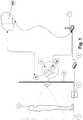
- the systemis applied to a fitting room 3 into which a user 4 is placed, and comprises:
- the system there illustratedincludes (optionally) a RFID tag code reader for reading RFID tags (not shown) attached to pieces of clothing worn by the user.
- Said RFID tag code readerincludes one or more RFID antennae 5 connected to a RFID hub 6, collaborating for performing the RFID tag reading operations.
- the RFID hub 6sends the RFID data to the remote computing entity SR, in this case via access router 7, directly or through local computing entity SL, the remote computing entity SR using the received data in order to associate said RFID data to the image or images of the user acquired or to be acquired.
- the local computing entity SLperforms at least part of the RFID reading process from data received from the RFID hub 6.
- the support 2is movable among a plurality of positions about at least one horizontal axis, as schematically illustrated in Figure 2 , in this case by means of a first articulation joint A1 between a portion 2b of the support 2, constituting or comprising a coupling arrangement, attached to the smartphone D, and an arm 2c attached to another portion 2a of the support 2 to be attached to the mirror 9.
- arm 2cis attached to portion 2a through a further articulation joint A2, in this case a ball joint which allows to move arm 2c (and hence support portion 2b and smartphone D) about further rotation axis (manually or automatically).
- a further articulation joint A2in this case a ball joint which allows to move arm 2c (and hence support portion 2b and smartphone D) about further rotation axis (manually or automatically).
- Both, arm 2c and articulation joint A2are optional elements, i.e. for a non-illustrated embodiment support 2 comprises portion 2b directly attached to portion 2a through articulation joint A1.
- Support 2comprises a coupling arrangement 2b for firmly coupling and holding the portable computing device D in a proper position for acquiring images of the user.
- said coupling arrangement 2bis implemented by means of two elastic clamping arms having an L-shaped cross-section, in order to allow (as illustrated) to hold the smartphone D without interfering in the field view of the built-in camera De, for a plurality of different portable computing devices D having their built-in cameras De in different positions.
- any other alternative coupling arrangement(meeting the requirements of not interfering in the field of view of the camera De) can be included in the system of the present invention, for non-illustrated embodiments, differing from the illustrated one in the number, shape and constitution of coupling elements and/or in the kind of coupling elements (suction-cups, magnets, etc.).
- the local computing entity SLis illustrated in the form of a single block placed within or attached to support portion 2a, 12a, although for other embodiments said entity SL is not placed within or attach to any portion of support 2, 12, but placed, at least in part, separated from the support 2, 12, although, for the embodiment of Figure 1 , being connected with an electric motor (not shown) kinematically connected to articulation joint A1 or to support portion 2b to automatically rotate it about an horizontal axis.
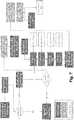
- FIG. 6A flowchart showing a possible operation process of the system of Figure 1 is shown in Figure 6 , where the local computing entity SL has been renamed as “Sheekr Dock", the application program running in the portable computing device D is referred as “Sheekr App” and the remote computing entity SR has been renamed as “Sheekr Server”.
- the useruses the "Sheekr App” to access to the service or "experience” provided by the system, i.e. said app is executed (manually or automatically) when the user approaches or enters the fitting room.
- the "Sheekr Dock”automatically sends to the "Sheekr Server” the user ID, indicated as “Sheekr ID”, which has been retrieved through the link provided by the digital attaching. Said validation is generally performed by the "Sheekr Server”.
- the "Sheekr Server”also "knows” the identity of the “Sheekr Dock”, as that identity is inferred from the communication through which the latter send the "Sheekr ID” to the "Sheekr Server".
- the "Sheekr Server”activates the "Sheekr Dock", the latter then controlling both the electrical motor (not shown) for moving the support 2 and the portable device attached thereto and also the operation of the built-in camera De of the portable device D, through the control of the "Sheekr App” (for example, via Bluetooth), such that after a first rotation step is performed a first photo of the user is taken, and so on until a fourth (or another number) rotation and photo are performed.
- the panoramic imagecan be downloaded to the portable device D and/or be made accessible to other users, such as users of a social network or community, in order to allow them to rank and/or express their opinion about it.
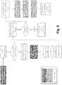
- Figure 7shows a flowchart also regarding a possible operation process of the system of Figure 1 , which is very similar to the one of Figure 6 , but including also the use of above mentioned RFID tag reader 5, 6.
- the flowchart of Figure 7includes the same steps as the flowchart of Figure 6 , with the addition of a further step for taking RFID data from antenna 5, performed according to the illustrated diagram before the rotation of the support and the taking of the photos, although for other embodiments it can be performed after or simultaneously there with.
- the flowchart of Figure 7differs from the one of Figure 6 also in that in the step for sending the photos to the "Sheekr Server” the RFID data is also sent thereto, the "Sheekr Server” associating the received RFID data to the panoramic image, such that the pieces of clothing there depicted are duly identified, and features associated thereto (price, size, model, colour, etc.) can thus be made virtually accessible to the user and/or to the users of a social network or community.
- Figure 4shows another embodiment of the first aspect of the invention, differing from the one of Figure 1 especially in that the support 12 is stationary and structurally different, and in that the system comprises an optical element 10 attached to the support 12 such that it remains at a predetermined distance and orientation with respect to the built-in camera Dc of the portable computing device D attached to the support 12, to allow, with a single shot, acquiring at least one distorted image of the user including different portions along her/his height, preferably her/his full body.
- said optical element 10is a convex mirror with its convex side facing the user placed in front of the main mirror 9 and also facing the built-in camera Dc, which for the illustrated embodiment is a rear built-in camera, such that the user can see in the front display touch screen Ds of the illustrated smartphone D the distorted reflection image of the user on the convex mirror 10, as shown in Figure 4 , or, preferably, a preview undistorted image of the user generated by a pre-correction of the distorted image performed by the application program, as shown in Figure 5 .
- Convex mirror 10includes some reference marks 10c which will be used to aid in the process to correct the distortion of the distorted acquired image in order to obtain a panoramic image therefrom.
- the front display touch screen Ds of the smartphone Dwill also display several graphic elements provided by the application program running therein, including a virtual button to be pressed by the user in order to start a timer countdown to trigger the acquiring of the one or more distorted images after a predetermined lapse of time.
- Support 12also comprises, as shown in Figures 4 and 5 , a coupling arrangement 12b for firmly coupling and holding the portable computing device D in a proper position for acquiring images of the user.
- said coupling arrangement 12bis a pocket-type coupling arrangement into which a lower portion of the smartphone D is housed and held, although for other non-illustrated embodiment other types of coupling arrangements can be used (clamps, magnets, suction-cups, etc.).
- the above mentioned predetermined distance between the convex mirror 10 and the camera Dcis defined by the length of the support bridge portion 12c which separates the pocket-like coupling arrangement 12b and the back wall 12a onto which the convex mirror 10 is attached.
- the above mentioned predetermined orientationis, in this case, determined by the angle defined, at least in the horizontal plane, between the convex mirror 10 and the major faces of the pocket-like coupling arrangement 12b, and thus of the smartphone D and camera Dc.
- the predetermined distance and orientation, and also the convexity of the convex mirror 10,are calculated to allow the reflection of the user 4 on the convex mirror 10 without the smartphone D interfering in between, to direct the reflected light towards the camera Dc of the smartphone D such that it can acquire an image of the user as reflected on the convex mirror 10, and to allow the reconstruction of the panoramic image by correcting the image distortion by image processing preferably by using the reference marks 10c.
- a virtual "PhotoButton”is activated by the “Sheekr App”, i.e. appears on the screen Ds.
- the userBy pressing said "PhotoButton”, the user starts a timer countdown to trigger the camera to take one or more distorted photos, generally one distorted photo per pose.
- the "Sheekr App”controls the smartphone D to send the "Sheekr ID” and the “Dock ID” to the "Sheekr Server", which is in charge of performing a validation of the "Sheekr ID” (for the Dock associated to the received "Dock ID”). If the "Sheekr ID” is not validated (wrong ID or unauthorised user), then the "experience” is cancelled.
- the "Sheekr App”controls the smartphone D to send the distorted photos to the "Sheekr Server", the latter performing a correction of the convex distortion thereof to obtain corresponding panoramic images.
- the "Sheekr Server" to the “Sheekr Server”optionally creates a user session with associated data (such as metadata) to the created images.
- the panoramic image(s)can be downloaded to the portable device D and/or put into validated mobile repository (as indicated in the Figure) and/or be made accessible to other users, such as users of a social network or community, in order to allow them to rank and/or express their opinion about it.
- Figure 9shows a flowchart very similar to the one of Figure 8 but including also the use of above mentioned RFID tag reader 5, 6.
- the flowchart of Figure 9includes the same steps as the flowchart of Figure 8 , with the addition of a requesting, by means of the "Sheekr App” to the here called “Sheekr Convex Dock” (i.e. local computing entity SL) for RFID data, the latter, in response to said request, taking the RFID antenna last data and sending said data to the "Sheekr App".
- a requestingby means of the "Sheekr App” to the here called “Sheekr Convex Dock” (i.e. local computing entity SL) for RFID data
- SLlocal computing entity
- the "Sheekr App”also sends, together with the distorted photos, the RFID data to the "Sheekr Server", the latter preferably associating the received RFID data to the panoramic image(s), such that the pieces of clothing there depicted are duly identified, and features associated thereto (price, size, model, colour, etc.) can thus be made virtually accessible to the user and/or to the users of a social network or community.
Landscapes
- Physics & Mathematics (AREA)
- General Physics & Mathematics (AREA)
- Engineering & Computer Science (AREA)
- Signal Processing (AREA)
- Multimedia (AREA)
- Health & Medical Sciences (AREA)
- Computer Networks & Wireless Communication (AREA)
- Toxicology (AREA)
- Electromagnetism (AREA)
- Theoretical Computer Science (AREA)
- Computer Security & Cryptography (AREA)
- General Health & Medical Sciences (AREA)
- Artificial Intelligence (AREA)
- Computer Vision & Pattern Recognition (AREA)
- Studio Devices (AREA)
- Human Computer Interaction (AREA)
- Telephone Function (AREA)
- Telephonic Communication Services (AREA)
- Details Of Cameras Including Film Mechanisms (AREA)
- Stereoscopic And Panoramic Photography (AREA)
- Structure And Mechanism Of Cameras (AREA)
- Accessories Of Cameras (AREA)
- Closed-Circuit Television Systems (AREA)
Description
- The present invention generally concerns, in a first aspect, to a portrait-like photographic system allowing acquiring images of a user placed in front of a mirror with a built-in camera of a computing device, and more particularly to a system allowing the use of the built-in cameras of the personal portable computing devices of any of a plurality of users to perform the images acquiring.
- A second aspect of the invention concerns to a fitting room comprising the system of the first aspect of the invention.
- A third aspect of the invention relates to a computer program comprising computer subprograms adapted to operate the system of the first aspect.
- Several portrait-like photographic systems are known in the art, including a mirror and a camera so that a user placed in front of the mirror can see her/his reflected image and capture one or more images of herself/himself showing the same pose adopted for the reflected image, by triggering the camera automatically or with the intervention of the user.
- Some patent documents disclosing some of said known systems are, for example,
EP1351172A1 andKR20140018599 - All of the known systems include at least one camera unremovably attached to a structural member, such as the mirror, generally behind the mirror, which is a one-way mirror or has a through opening though which the camera acquires the images of the user.
- In most of said known systems the camera is not a built-in camera of a computing device.
JP2002325160A - International patent application
WO2009029949A1 discloses a fitting room including an interactive display device which includes a camera fitted thereto and a computer terminal. Although, for an embodiment, a communication module of the computer terminal contains a mobile device component which can receive and send images taken by the camera fitted in the display, no mention regarding the inclusion or use of a camera built-in the mobile device module is done at all in said document. - International patent application
WO2006021824 discloses a system where the camera is a built-in camera of a computer device particularly of what is called as a MMS terminal suitable for sending MMS through a mobile phone communication network. However, the camera is placed within the surface of a mirror, and hence the terminal including the camera is unremovably attached to that mirror, or, as stated in said document "locally installed". - Although
WO2006021824 discusses the advantages that using a smartphone have for taking self-photographs (also known as selfies), particularly associated to the fact that the acquired images can be sent through a mobile phone communication network, the proposal made therein is focused on overcoming the disadvantages that the use of said smartphones have, when the users use their own smartphones for taking the self-photographs ("the distance between the camera and the user is limited by the arm's length so the user needs assistance provided by another person"). Hence, the solution proposed byWO2006021824 is to integrate one smartphone within the mirror, but once the smartphone is placed within the mirror it is not portable anymore, but on contrary it becomes a stationary computing device. - None of the known systems raises the problem associated to the fact that there are many applications, such as fitting rooms, where (in most countries) it is legally forbidden to use a system including an attached camera, for privacy matters.
WO2006021824 includes the features defined in the preamble clause ofclaim 1 of the present invention, but said document does not only not raises the above mentioned problem (nor any technical problem associated thereto), but even teaches away from providing a solution to that problem, as the system proposed therein includes a stationary camera.- It is therefore necessary to provide an alternative to the state of the art which covers the gaps found therein, and provides a solution to the above mentioned problem.
- To that end, the present invention relates, in a first aspect, to a fitting room according to
claim 1, comprising, in a known manner: - a mirror; and
- attaching means for attaching, with respect to said mirror, a computing device having at least one built-in camera, such that the built-in camera is positioned to acquire images of a user placed in front of said mirror.
- In contrast to the prior art systems, in the system of the first aspect of the invention, in a characteristic manner:
- the above mentioned attaching means comprise a support physically attached to said mirror, or to a structural member fixed thereto, said support being configured and arranged to interchangeably and removably attach thereto any of a plurality of portable computing devices having built-in cameras (smartphones, tablets, etc.); and
- the system further comprises a local computing entity adapted to establish a communication link with the portable computing device attached or to be attached to said support, in order to acquire one or more images of a user placed in front of said mirror with the built-in camera of the portable computing device once attached to the support.
- Hence, the system provided by the present invention constitutes a solution to the new technical problem associated to the above mentioned problem of forbiddance of using systems including attached cameras, for some applications.
- For an embodiment, the system of the first aspect of the invention further comprising the portable computing device(s) removably attached to the support.
- According to an embodiment, the above mentioned communication link is a wired or wireless communication bidirectional link, and the local computing entity and the portable computing device are adapted to automatically establish said wired or wireless communication bidirectional link with each other once the portable computing device is attached to said support or located within a determined area proximate thereto, to perform an univocal association between the local computing entity and the portable computing device, for at least identification purposes.
- For some embodiments, said bidirectional link is a matching or pairing between the local computing entity and the portable computing device, or a simpler link, i.e. a link including a simpler negotiation.
- Preferably, the communication bidirectional link is of a wireless type, such as a WiFi or Bluetooth link, or even a NFC link.
- For an embodiment, the local computing entity is adapted to receive, through said communication bidirectional link, at least a user ID associated to the portable computing device, univocally associated therewith, or to an application program running in the portable computing device, and to identify and validate said user ID.
- For another embodiment, the system of the first aspect of the invention further comprises a remote computing entity adapted to establish a bidirectional communication with the portable computing device and/or with the local computing entity, to receive at least a user ID associated to the portable computing device, univocally associated with the local computing device, or to an application program running in the portable computing device, and to identify and validate said user ID.
- According to an embodiment, the local computing entity is adapted to control, by itself or under control of said remote computing entity, the at least one built-in camera of the portable computing device to acquire one or more images of a user located in front of the mirror.
- Regarding the above mentioned support, for an embodiment, it preferably comprises a coupling arrangement for firmly coupling and holding the portable computing device in a proper position for acquiring images of the user.
- For an embodiment, the support is movable among a plurality of positions about at least one horizontal axis under the control of the local computing entity, by itself or under control of the remote computing entity, once the user ID has been validated, synchronously with the acquiring of one or more images such that at least one image is acquired for each of said plurality of positions, so that a sequence of images covering different portions of the user along her/his height are acquired.
- For an alternative embodiment, the support is stationary, the system including an optical element attached to the support such that it remains at a predetermined distance and orientation with respect to the built-in camera of the portable computing device attached to the support, to allow, with a single shot, acquiring at least one distorted image of the user including different portions along her/his height, preferably the full body thereof.
- For a preferred variant of said embodiment, the above mentioned mirror is a main mirror and said optical element is a convex mirror with its convex side facing the user placed in front of the main mirror and also facing the built-in camera, which is a rear built-in camera, the portable computing device comprising a front display touch screen displaying graphic elements provided by said application program when running in the portable computing device, including a virtual button to be pressed by the user in order to start a timer countdown to trigger said acquiring of at least one distorted image after a predetermined lapse of time enough as to allow the user to adopt the desired pose in front of the mirror, and also displaying the distorted reflection image of the user on the convex mirror or a preview undistorted image of the user generated by a pre-correction of the distorted image performed by the application program.
- Other alternative optical elements are also covered for other variants of the above mentioned embodiment, including reflective and transmissive optical elements, or a combination thereof, such as prisms having appropriate shapes and refraction indexes to allow the acquiring of a distorted image covering different portions of the user with the built-in camera of the portable computing device attached to the support.
- In order to adapt the system to portable computing devices differing at least in that their rear built-in cameras are placed in different positions, according to an embodiment, the optical element is movable with respect to the support, the system comprising driving means including an electric motor and a cinematic chain mechanically connected to the movable optical element, and a position sensor for detecting the position of the rear built-in camera of the portable computing device attached to the support, wherein the local computing entity is connected to the output of said position sensor and to the input of said electric motor to control the latter to move the optical element based on the detected position
- For an embodiment, the portable computing device is adapted to, once the user ID has been validated:
- send the sequence of images or the at least one distorted image to the local computing entity or to the remote computing entity, and wherein the local computing entity or the remote computing entity is adapted to process the received sequence of images or the received distorted image to obtain a single panoramic image of the user from, respectively, a composition of the sequence of images or a distortion correction of the at least one distorted image; or
- process the acquired sequence of images or the acquired distorted image to obtain a single panoramic image of the user from, respectively, a composition of the sequence of images or a distortion correction of the at least one distorted image.
- Additionally, for another embodiment, the system of the first aspect of the invention further comprises at least one tag code reader for reading ID tags attached to pieces of clothing worn by the user, wherein the local computing entity and/or the remote computing entity are connected to the output of said at least one tag code reader, or implement a portion thereof, to obtain ID data identifying the pieces of clothing worn by the user placed in front of the mirror, in order to associate said ID data to the image or images of the user acquired or to be acquired.
- The first aspect of the invention is a preferred and relevant application of the system of the invention, because in most countries placing cameras within fitting rooms is illegal, for privacy matters, and hence the invention provides an acquiring of portrait-like images of users trying on different pieces of clothes with their own portable computing devices, such as smartphones, but with a much higher quality than the one which can be obtained with a simple selfie performed by the user by holding a smartphone directly with his hands or with a selfie stick, and where the acquired images do not show the user adopting a strange pose as it happens when she/he is holding the smartphone but the same pose as she/he sees reflected on the mirror.
- Moreover, fitting rooms are usually of small dimensions, i.e. they enclose small spaces, so that the distance from the mirror and the user is too small as to acquire a full-body image thereof with the camera of a smartphone. Therefore, the above described embodiments regarding the obtaining of a panoramic image of the user are of particular interest for the first aspect of the invention, i.e. for the application of the system to fitting room.
- A second aspect of the invention relates to a computer program according to claim 15, comprising computer subprograms including code instructions that when executed on respective processors of at least the portable computing device and the local computing entity of the portrait-like photographic system of the first aspect of the invention perform the operations thereof involving the portable computing device and the local computing entity, including the above mentioned communication link establishment and image acquiring.
- The subprogram executed in the processor of the portable computing device is preferably implemented in the form of the above mentioned application program, through which the user (if allowed, i.e. if her/his user ID is validated) can access to and interact with the service provided by the system, i.e. to the acquiring of portrait-like images and subsequent delivering, processing and storing of the images, locally and, preferably, remotely (for example in a cloud server) in order to share them with people belonging to a virtual community or social network to ask for their opinion about the images.
- The previous and other advantages and features will be more fully understood from the following detailed description of embodiments, with reference to the attached drawings, which must be considered in an illustrative and non-limiting manner, in which:
Figure 1 schematically depicts the system of the first aspect of the present invention applied to a fitting room, according to the second aspect of the invention, for an embodiment;Figure 2 is an enlarged view of the support and smartphone shown inFigure 1 , where different rotation positions thereof are depicted;Figure 3 is a perspective view of the support of the system of the first aspect of the invention attached to a smartphone by means of a specific clamping arrangement, for an embodiment;Figure 4 schematically shows the system of the first aspect of the present invention applied to a fitting room for another embodiment;Figure 5 is an enlarged view of the support, convex mirror and smartphone shown inFigure 4 ;Figure 6 is a flowchart showing a possible operation process of the system of the present invention for the embodiment shown inFigure 1 , but without the inclusion and/or operation of the elements identified by thenumerals Figure 7 is a flowchart similar to the one ofFigure 6 , also applied to the embodiment ofFigure 1 , but including the operation of said 5 and 6 elements, i.e. actions associated to an RFID reading process;Figure 8 is a flowchart showing a possible operation process of the system of the present invention for the embodiment shown inFigure 4 , but without the inclusion and/or operation of the elements identified by thenumerals Figure 9 is a flowchart similar to the one ofFigure 8 , also applied to the embodiment ofFigure 4 , but including the operation of said 5 and 6 elements, i.e. actions associated to an RFID reading process.- Two alternative embodiments of the portrait-like photographic system and the fitting room of, respectively, the first aspect of the invention are depicted in
Figures 1 and4 . - For both of said alternative embodiments, the system is applied to a
fitting room 3 into which auser 4 is placed, and comprises: - a
mirror 9, in front of which theuser 4 is placed; - a
support mirror 9, and being configured and arranged to interchangeably and removably attach thereto any of a plurality of portable computing devices D having built-in cameras Dc (in the Figures, a smartphone D is attached to therespective support 2, 12); - a local computing entity SL adapted to establish a communication bidirectional link (preferably wireless, such as WiFi, Bluetooh or NFC) with the portable computing device D attached or to be attached to the
support - a remote computing entity SR (such as a cloud server) adapted to establish a bidirectional communication (as indicated by the illustrated arrow lines) with the portable computing device D (for example via a 3G or 4G mobile phone communication network) and with the local computing entity SL, in the latter case via a
WiFi access router 7 connected to the remote computing entity SR via a wired (for example, an ADSL or fiber-optic connection) or wireless communication network. - Any other type of communication technology and&/or protocol can be used, alternatively to the ones mentioned above, for the mentioned bidirectional communications.
- For both,
Figures 1 and4 , the system there illustrated includes (optionally) a RFID tag code reader for reading RFID tags (not shown) attached to pieces of clothing worn by the user. Said RFID tag code reader includes one ormore RFID antennae 5 connected to aRFID hub 6, collaborating for performing the RFID tag reading operations. TheRFID hub 6 sends the RFID data to the remote computing entity SR, in this case viaaccess router 7, directly or through local computing entity SL, the remote computing entity SR using the received data in order to associate said RFID data to the image or images of the user acquired or to be acquired. - Alternatively, the local computing entity SL performs at least part of the RFID reading process from data received from the
RFID hub 6. - For the embodiment of
Figure 1 , as shown in detail inFigure 2 , thesupport 2 is movable among a plurality of positions about at least one horizontal axis, as schematically illustrated inFigure 2 , in this case by means of a first articulation joint A1 between aportion 2b of thesupport 2, constituting or comprising a coupling arrangement, attached to the smartphone D, and anarm 2c attached to anotherportion 2a of thesupport 2 to be attached to themirror 9. - For the embodiment illustrated in
Figure 2 ,arm 2c is attached toportion 2a through a further articulation joint A2, in this case a ball joint which allows to movearm 2c (and hence supportportion 2b and smartphone D) about further rotation axis (manually or automatically). - Both,
arm 2c and articulation joint A2, are optional elements, i.e. for anon-illustrated embodiment support 2 comprisesportion 2b directly attached toportion 2a through articulation joint A1. Support 2 comprises acoupling arrangement 2b for firmly coupling and holding the portable computing device D in a proper position for acquiring images of the user. For the embodiment illustrated inFigure 3 , saidcoupling arrangement 2b is implemented by means of two elastic clamping arms having an L-shaped cross-section, in order to allow (as illustrated) to hold the smartphone D without interfering in the field view of the built-in camera De, for a plurality of different portable computing devices D having their built-in cameras De in different positions.- Any other alternative coupling arrangement (meeting the requirements of not interfering in the field of view of the camera De) can be included in the system of the present invention, for non-illustrated embodiments, differing from the illustrated one in the number, shape and constitution of coupling elements and/or in the kind of coupling elements (suction-cups, magnets, etc.).
- For the embodiments illustrated in
Figures 1 and4 , the local computing entity SL is illustrated in the form of a single block placed within or attached to supportportion support support Figure 1 , being connected with an electric motor (not shown) kinematically connected to articulation joint A1 or to supportportion 2b to automatically rotate it about an horizontal axis. - A flowchart showing a possible operation process of the system of
Figure 1 is shown inFigure 6 , where the local computing entity SL has been renamed as "Sheekr Dock", the application program running in the portable computing device D is referred as "Sheekr App" and the remote computing entity SR has been renamed as "Sheekr Server". - In the flowchart, the operations performed by the "Sheekr Dock" are illustrated in dark grey, the operations carried out by the Sheekr Server by light grey, and the ones performed by the "Sheekr App" in white.
- The user uses the "Sheekr App" to access to the service or "experience" provided by the system, i.e. said app is executed (manually or automatically) when the user approaches or enters the fitting room.
- According to the flowchart of
Figure 6 , first, the above mentioned bidirectional link, here called as "digital attaching", is realised between "Sheekr Dock" and "Sheekr App". A physical shake of the portable device D is performed to secure the attaching, i.e. to confirm/validate that the device D "digitally attached" (through its "Sheeker App") to "Sheekr Dock" is the one of the user placed in front of themirror 9, in order to avoid, for example, an undesired digital attaching to a device D of a person placed near the "Sheekr Dock" which is not the user (in this case, said digital attaching would have been established automatically when the portable device D of said other user is within the coverage field of (for example) a WiFi transceiver of the "Sheekr Dock" used for said digital attaching). - If that digital attaching is not validated (generally by the "Sheekr Dock"), the "experience" is cancelled.
- If the digital attaching is validated, the "Sheekr Dock" automatically sends to the "Sheekr Server" the user ID, indicated as "Sheekr ID", which has been retrieved through the link provided by the digital attaching. Said validation is generally performed by the "Sheekr Server". The "Sheekr Server" also "knows" the identity of the "Sheekr Dock", as that identity is inferred from the communication through which the latter send the "Sheekr ID" to the "Sheekr Server".
- If the "Sheekr ID" is not validated (wrong ID or unauthorised user), then the "experience" is cancelled.
- If the "Sheekr ID" is validated, then the "Sheekr Server" activates the "Sheekr Dock", the latter then controlling both the electrical motor (not shown) for moving the
support 2 and the portable device attached thereto and also the operation of the built-in camera De of the portable device D, through the control of the "Sheekr App" (for example, via Bluetooth), such that after a first rotation step is performed a first photo of the user is taken, and so on until a fourth (or another number) rotation and photo are performed. - Once, all the photos are taken, preferably covering the full body of the
user 4, they are sent by the "Sheekr Dock" to the "Sheekr Server", the latter composing the panoramic image of the user therefrom, and, optionally, creating a user session with associated data (such as metadata) to the created image. - Then, the "experience" is finished, and the "Sheekr Dock" and "Sheekr App" are reset, or their operation is just stopped.
- The panoramic image can be downloaded to the portable device D and/or be made accessible to other users, such as users of a social network or community, in order to allow them to rank and/or express their opinion about it.
Figure 7 shows a flowchart also regarding a possible operation process of the system ofFigure 1 , which is very similar to the one ofFigure 6 , but including also the use of above mentionedRFID tag reader - The flowchart of
Figure 7 includes the same steps as the flowchart ofFigure 6 , with the addition of a further step for taking RFID data fromantenna 5, performed according to the illustrated diagram before the rotation of the support and the taking of the photos, although for other embodiments it can be performed after or simultaneously there with. - The flowchart of
Figure 7 differs from the one ofFigure 6 also in that in the step for sending the photos to the "Sheekr Server" the RFID data is also sent thereto, the "Sheekr Server" associating the received RFID data to the panoramic image, such that the pieces of clothing there depicted are duly identified, and features associated thereto (price, size, model, colour, etc.) can thus be made virtually accessible to the user and/or to the users of a social network or community. Figure 4 shows another embodiment of the first aspect of the invention, differing from the one ofFigure 1 especially in that thesupport 12 is stationary and structurally different, and in that the system comprises anoptical element 10 attached to thesupport 12 such that it remains at a predetermined distance and orientation with respect to the built-in camera Dc of the portable computing device D attached to thesupport 12, to allow, with a single shot, acquiring at least one distorted image of the user including different portions along her/his height, preferably her/his full body.- Particularly, as shown in
Figure 4 and more clearly inFigure 5 , saidoptical element 10 is a convex mirror with its convex side facing the user placed in front of themain mirror 9 and also facing the built-in camera Dc, which for the illustrated embodiment is a rear built-in camera, such that the user can see in the front display touch screen Ds of the illustrated smartphone D the distorted reflection image of the user on theconvex mirror 10, as shown inFigure 4 , or, preferably, a preview undistorted image of the user generated by a pre-correction of the distorted image performed by the application program, as shown inFigure 5 . Convex mirror 10 includes somereference marks 10c which will be used to aid in the process to correct the distortion of the distorted acquired image in order to obtain a panoramic image therefrom.- In use, the front display touch screen Ds of the smartphone D will also display several graphic elements provided by the application program running therein, including a virtual button to be pressed by the user in order to start a timer countdown to trigger the acquiring of the one or more distorted images after a predetermined lapse of time.
Support 12 also comprises, as shown inFigures 4 and5 , acoupling arrangement 12b for firmly coupling and holding the portable computing device D in a proper position for acquiring images of the user. In the illustrated embodiment, saidcoupling arrangement 12b is a pocket-type coupling arrangement into which a lower portion of the smartphone D is housed and held, although for other non-illustrated embodiment other types of coupling arrangements can be used (clamps, magnets, suction-cups, etc.).- As shown in
Figures 4 and5 , the above mentioned predetermined distance between theconvex mirror 10 and the camera Dc, is defined by the length of thesupport bridge portion 12c which separates the pocket-like coupling arrangement 12b and theback wall 12a onto which theconvex mirror 10 is attached. The above mentioned predetermined orientation is, in this case, determined by the angle defined, at least in the horizontal plane, between theconvex mirror 10 and the major faces of the pocket-like coupling arrangement 12b, and thus of the smartphone D and camera Dc. - The predetermined distance and orientation, and also the convexity of the
convex mirror 10, are calculated to allow the reflection of theuser 4 on theconvex mirror 10 without the smartphone D interfering in between, to direct the reflected light towards the camera Dc of the smartphone D such that it can acquire an image of the user as reflected on theconvex mirror 10, and to allow the reconstruction of the panoramic image by correcting the image distortion by image processing preferably by using the reference marks 10c. - Flowcharts showing possible operation processes of the system of
Figure 4 are shown inFigures 8 and9 , using the same terminology and grey codes as in the flowcharts ofFigures 6 and7 . - According to the flowchart of
Figure 8 , first, the above described "digital attaching" between the "Sheekr Dock" and the "Sheekr App" is performed. In contrast to the flowcharts ofFigures 6 and7 , an attaching validation is not needed for the flowchart ofFigure 8 . - Once the digital attaching has been achieved, a virtual "PhotoButton" is activated by the "Sheekr App", i.e. appears on the screen Ds. By pressing said "PhotoButton", the user starts a timer countdown to trigger the camera to take one or more distorted photos, generally one distorted photo per pose.
- The "Sheekr App" controls the smartphone D to send the "Sheekr ID" and the "Dock ID" to the "Sheekr Server", which is in charge of performing a validation of the "Sheekr ID" (for the Dock associated to the received "Dock ID"). If the "Sheekr ID" is not validated (wrong ID or unauthorised user), then the "experience" is cancelled.
- If the "Sheekr ID" is valid, then the "Sheekr App" controls the smartphone D to send the distorted photos to the "Sheekr Server", the latter performing a correction of the convex distortion thereof to obtain corresponding panoramic images.
- Once, all the photos are corrected, the "Sheekr Server" to the "Sheekr Server" optionally creates a user session with associated data (such as metadata) to the created images.
- Then, the "experience" is finished, and the panoramic image(s) can be downloaded to the portable device D and/or put into validated mobile repository (as indicated in the Figure) and/or be made accessible to other users, such as users of a social network or community, in order to allow them to rank and/or express their opinion about it.
- The order of some of the steps of the flowchart of
Figure 8 could be different to the illustrated one. For example, the taking of photos could be performed after the "Sheekr ID" validation. - Similarly to
Figure 7 ,Figure 9 shows a flowchart very similar to the one ofFigure 8 but including also the use of above mentionedRFID tag reader - The flowchart of
Figure 9 includes the same steps as the flowchart ofFigure 8 , with the addition of a requesting, by means of the "Sheekr App" to the here called "Sheekr Convex Dock" (i.e. local computing entity SL) for RFID data, the latter, in response to said request, taking the RFID antenna last data and sending said data to the "Sheekr App". In this case, the "Sheekr App" also sends, together with the distorted photos, the RFID data to the "Sheekr Server", the latter preferably associating the received RFID data to the panoramic image(s), such that the pieces of clothing there depicted are duly identified, and features associated thereto (price, size, model, colour, etc.) can thus be made virtually accessible to the user and/or to the users of a social network or community. - A person skilled in the art could introduce changes and modifications in the embodiments described without departing from the scope of the invention as it is defined in the attached claims.
Claims (15)
- A fitting room, comprising:- a mirror (9); and- attaching means for attaching, with respect to said mirror (9), a computing device having at least one built-in camera, such that the built-in camera is positioned to acquire images of a user placed in front of said mirror (9);wherein the fitting room ischaracterised in that said computing device is a portable computing device (D) having a built-in camera (Dc), andin that:- said attaching means comprise a support (2, 12) physically attached to said mirror (9, 10), or to a structural member fixed thereto, said support (2, 12) being configured and arranged to interchangeably and removably attach thereto any of a plurality of said portable computing devices (D) having built-in cameras (Dc); and-in that the fitting room further comprises a system which comprises a local computing entity (SL) adapted to establish a communication link with the portable computing device (D) attached or to be attached to said support (2, 12), in order to acquire one or more images of a user placed in front of said mirror (9, 10) with the built-in camera (Dc) of the portable computing device (D) once attached to the support (2, 12).
- The fitting room according to claim 1, wherein said system is a portrait-like photographic system which comprises said portable computing device (D) removably attached to said support (2, 12), and said local computing entity (SL).
- The fitting room according to claim 1 or 2, wherein said communication link is a wired or wireless communication bidirectional link, and wherein said local computing entity (SL) and said portable computing device (D) are adapted to automatically establish said wired or wireless communication bidirectional link with each other once the portable computing device (D) is attached to said support (2, 12).
- The fitting room according to claim 1 or 2, wherein said communication link is a wired or wireless communication bidirectional link, and wherein said local computing entity (SL) and said portable computing device (D) are adapted to automatically establish said wired or wireless communication bidirectional link with each other once the portable computing device (D) is located within a determined area proximate thereto, to perform an univocal association between the local computing entity (SL) and the portable computing device, for at least identification purposes.
- The fitting room according to claim 3 or 4, wherein said local computing entity (SL) is adapted to receive, through said communication bidirectional link, at least a user ID associated to the portable computing device (D), univocally associated therewith, or to an application program running in the portable computing device (D), and to identify and validate said user ID.
- The fitting room according to claim 3, 5 or 5, wherein said system comprises a remote computing entity (SR) adapted to establish a bidirectional communication with the portable computing device (D) and/or with the local computing entity (SL), to receive at least a user ID associated to the portable computing device (D), univocally associated with the local computing device (SL), or to an application program running in the portable computing device (D), and to identify and validate said user ID.
- The fitting room according to claim 5 or 6, wherein said local computing entity (SL) is adapted to control, by itself or under control of said remote computing entity (SR), the at least one built-in camera (Dc) of the portable computing device (D) to acquire one or more images of a user located in front of the mirror (9).
- The fitting room according to claim 7, wherein said support (2) is movable among a plurality of positions about at least one horizontal axis under the control of the local computing entity (SL), by itself or under control of said remote computing entity (SR), once said user ID has been validated, synchronously with said acquiring of one or more images such that at least one image is acquired for each of said plurality of positions, so that a sequence of images covering different portions of the user along her/his height are acquired.
- The fitting room according to claim 5, 6 or 7, wherein said support (12) is stationary, the system including an optical element (10) attached to the support (12) such that it remains at a predetermined distance and orientation with respect to the at least one built-in camera (Dc) of the portable computing device (D) attached to the support (12), to allow, with a single shot, acquiring at least one distorted image of the user including different portions along her/his height.
- The fitting room according to claim 9, wherein said mirror (9) is a main mirror and said optical element (10) is a convex mirror with its convex side facing the user placed in front of said main mirror (9) and also facing the built-in camera (Dc), which is a rear built-in camera, the portable computing device (D) comprising a front display touch screen (Ds) displaying graphic elements provided by said application program when running in the portable computing device (D), including a virtual button to be pressed by the user in order to start a timer countdown to trigger said acquiring of at least one distorted image, and also displaying the distorted reflection image of the user on the convex mirror (10) or a preview undistorted image of the user generated by a pre-correction of the distorted image performed by the application program.
- The fitting room according to any of the previous claims, wherein said support (2, 12) comprises a coupling arrangement (2b, 12b) for firmly coupling and holding the portable computing device (D) in a proper position for acquiring images of the user.
- The fitting room according to claim 11 when depending on claim 9 or 10, wherein said optical element (10) is movable with respect to said support (12), the system comprising driving means including an electric motor and a cinematic chain mechanically connected to the movable optical element, and a position sensor for detecting the position of the rear built-in camera (Dc) of the portable computing device (D) attached to the support (12), wherein the local computing entity (SL) is connected to the output of said position sensor and to the input of said electric motor to control the latter to move the optical element based on the detected position, in order to adapt the system to portable computing devices (D) differing at least in that their rear built-in cameras (Dc) are placed in different positions.
- The fitting room according to any of claims 7 to 10 when depending on claim 2, wherein the portable computing device (D) is adapted, once the user ID has been validated:- to send the sequence of images or the at least one distorted image to the local computing entity (SL) or to the remote computing entity (SR), and wherein the local computing entity (SL) or the remote computing entity (SR) is adapted to process the received sequence of images or the received distorted image to obtain a single panoramic image of the user from, respectively, a composition of the sequence of images or a distortion correction of the at least one distorted image; or- to process by itself the acquired sequence of images or the acquired distorted image to obtain a single panoramic image of the user from, respectively, a composition of the sequence of images or a distortion correction of the at least one distorted image.
- The fitting room according to any of the previous claims, wherein said system further comprises at least one tag code reader (5, 6) for reading ID tags attached to pieces of clothing worn by the user, wherein the local computing entity (SL) and/or the remote computing entity (SR) are connected to the output of said at least one tag code reader (5, 6), or implement a portion thereof, to obtain ID data identifying the pieces of clothing worn by the user placed in front of the mirror (9), in order to associate said ID data to the image or images of the user acquired or to be acquire.
- Computer program, comprising computer subprograms including code instructions that when executed on respective processors of at least the portable computing device (D) and the local computing entity (SL) of the portrait-like photographic system of the fitting room of any of claims 2 to 14 perform the operations thereof involving the portable computing device (D) and the local computing entity (SL), including said communication link establishment and said image acquiring once the portable computing device is attached to the support of the fitting room.
Priority Applications (6)
| Application Number | Priority Date | Filing Date | Title |
|---|---|---|---|
| EP16382151.5AEP3229071B1 (en) | 2016-04-06 | 2016-04-06 | A fitting room comprising a portrait-like photographic system and a computer program |
| ES16382151TES2865328T3 (en) | 2016-04-06 | 2016-04-06 | A fitting room comprising a portrait-type photography system and a computer program |
| JP2019503630AJP6821786B2 (en) | 2016-04-06 | 2017-04-05 | Fitting room with portrait photography system and computer program |
| PCT/EP2017/058151WO2017174677A1 (en) | 2016-04-06 | 2017-04-05 | A fitting room comprising a portrait photographic system, and a computer program |
| CN201780031554.XACN109313380B (en) | 2016-04-06 | 2017-04-05 | Fitting room comprising a portrait photographing system and computer program |
| US16/091,623US11249373B2 (en) | 2016-04-06 | 2017-04-05 | Fitting room comprising a portrait photographic system, and a computer program |
Applications Claiming Priority (1)
| Application Number | Priority Date | Filing Date | Title |
|---|---|---|---|
| EP16382151.5AEP3229071B1 (en) | 2016-04-06 | 2016-04-06 | A fitting room comprising a portrait-like photographic system and a computer program |
Publications (2)
| Publication Number | Publication Date |
|---|---|
| EP3229071A1 EP3229071A1 (en) | 2017-10-11 |
| EP3229071B1true EP3229071B1 (en) | 2021-01-20 |
Family
ID=55809057
Family Applications (1)
| Application Number | Title | Priority Date | Filing Date |
|---|---|---|---|
| EP16382151.5AActiveEP3229071B1 (en) | 2016-04-06 | 2016-04-06 | A fitting room comprising a portrait-like photographic system and a computer program |
Country Status (6)
| Country | Link |
|---|---|
| US (1) | US11249373B2 (en) |
| EP (1) | EP3229071B1 (en) |
| JP (1) | JP6821786B2 (en) |
| CN (1) | CN109313380B (en) |
| ES (1) | ES2865328T3 (en) |
| WO (1) | WO2017174677A1 (en) |
Families Citing this family (4)
| Publication number | Priority date | Publication date | Assignee | Title |
|---|---|---|---|---|
| US20220174242A1 (en)* | 2020-12-01 | 2022-06-02 | II Robert E. Culver | Smart mirror architecture |
| CN112702510A (en)* | 2020-12-17 | 2021-04-23 | 珠海格力电器股份有限公司 | Information distribution method, control device and system, and storage medium |
| WO2023276819A1 (en)* | 2021-06-29 | 2023-01-05 | キヤノン株式会社 | Imaging system |
| WO2023162079A1 (en)* | 2022-02-24 | 2023-08-31 | 株式会社スクリエ | Intraoral imaging aid |
Family Cites Families (19)
| Publication number | Priority date | Publication date | Assignee | Title |
|---|---|---|---|---|
| JP2002207802A (en) | 2000-12-19 | 2002-07-26 | Shima Seiki Mfg Ltd | Method and device for aiding sales of apparel product and fitting room |
| JP2002208067A (en) | 2001-01-04 | 2002-07-26 | Yoshiaki Masuno | Photography system |
| JP2002325160A (en)* | 2001-02-22 | 2002-11-08 | Kazuhiko Suzuki | Photographing/distribution system |
| TWI280517B (en)* | 2003-05-19 | 2007-05-01 | Checkpoint Systems Inc | Article identification and tracking using electronic shadows created by RFID tags |
| JP2005283871A (en) | 2004-03-29 | 2005-10-13 | Iiyama Corp | Photographic printing device |
| HUP0401767A2 (en) | 2004-08-27 | 2006-02-28 | Istvan Kertesz | Outdoor mms terminal and method for operating of said terminal |
| CN1799458A (en)* | 2005-12-20 | 2006-07-12 | 滕英 | Omnidirectional electronic mirror and its using method |
| CN101136096A (en)* | 2006-08-31 | 2008-03-05 | 林�智 | Dress ornament evaluating and matching system and method on internet |
| US20090059175A1 (en)* | 2007-08-30 | 2009-03-05 | The Big Space Ltd. | Display arrangement |
| GB0820416D0 (en)* | 2008-11-07 | 2008-12-17 | Otus Technologies Ltd | Panoramic camera |
| KR20140053885A (en)* | 2011-04-18 | 2014-05-08 | 아이시360, 인코포레이티드 | Apparatus and method for panoramic video imaging with mobile computing devices |
| KR20130043769A (en) | 2011-10-21 | 2013-05-02 | (주)휴맥스 | Communication apparatus and method using a bump |
| CN202810235U (en)* | 2012-07-05 | 2013-03-20 | 广州市水晶球信息技术有限公司 | Interactive multifunctional fitting room |
| KR20140018599A (en) | 2012-08-02 | 2014-02-13 | (주)유한프리젠 | Fitting room sysyem and method for customized service |
| CN106165536B (en) | 2014-02-25 | 2018-11-06 | 飞利浦灯具控股公司 | Method and apparatus for wirelessly controlling lighting effects of networked light sources |
| US10007934B2 (en)* | 2014-07-21 | 2018-06-26 | Greystone Data Technology, Inc. | System and method for self-performing a cosmetic evaluation of an electronic device |
| CN204119349U (en)* | 2014-09-11 | 2015-01-21 | 源德盛塑胶电子(深圳)有限公司 | A kind of integral type self-timer |
| US9348198B1 (en)* | 2015-02-19 | 2016-05-24 | Leonard Adams | Mirrored photographing system |
| US9243741B1 (en)* | 2015-04-20 | 2016-01-26 | Intellectual Fortress, LLC | Telescoping monopod apparatus for holding photographic instrument |
- 2016
- 2016-04-06EPEP16382151.5Apatent/EP3229071B1/enactiveActive
- 2016-04-06ESES16382151Tpatent/ES2865328T3/enactiveActive
- 2017
- 2017-04-05USUS16/091,623patent/US11249373B2/enactiveActive
- 2017-04-05WOPCT/EP2017/058151patent/WO2017174677A1/ennot_activeCeased
- 2017-04-05JPJP2019503630Apatent/JP6821786B2/enactiveActive
- 2017-04-05CNCN201780031554.XApatent/CN109313380B/enactiveActive
Non-Patent Citations (1)
| Title |
|---|
| None* |
Also Published As
| Publication number | Publication date |
|---|---|
| JP2019522824A (en) | 2019-08-15 |
| WO2017174677A1 (en) | 2017-10-12 |
| EP3229071A1 (en) | 2017-10-11 |
| US11249373B2 (en) | 2022-02-15 |
| JP6821786B2 (en) | 2021-01-27 |
| ES2865328T3 (en) | 2021-10-15 |
| US20190121221A1 (en) | 2019-04-25 |
| CN109313380B (en) | 2021-09-21 |
| CN109313380A (en) | 2019-02-05 |
Similar Documents
| Publication | Publication Date | Title |
|---|---|---|
| EP3229071B1 (en) | A fitting room comprising a portrait-like photographic system and a computer program | |
| JP6205072B2 (en) | Imaging control apparatus, imaging control method, camera, camera system, and program | |
| WO2017204081A1 (en) | Image processing system, image processing program, and image processing method | |
| CN104820567B (en) | It is a kind of to control method, equipment and the system taken pictures using writing pencil | |
| JP5928551B2 (en) | Information processing system, information device, wearable information device, information device function execution method, wearable information device information notification method, wearable information device information device control method, wearable information device image transmission method, and program | |
| US8803997B2 (en) | Method and device for controlling remote capturing of an image based on detection of a predetermined change in the image | |
| CN107111139A (en) | Apparatus and method for display content | |
| JP6206645B2 (en) | Portable terminal, photographing method and program | |
| KR102116526B1 (en) | Smart mirror | |
| CN103905702A (en) | Glasses camera with wifi function | |
| CA2876412A1 (en) | Device and method for eye tracking data trigger arrangement | |
| JPWO2018008101A1 (en) | Image providing system, image providing method, and program | |
| US9661222B2 (en) | Electronic apparatus and method for controlling the same | |
| EP3520071B1 (en) | Consistent spherical photo and video orientation correction | |
| KR101369974B1 (en) | Usb real image projector | |
| KR20200050095A (en) | Method for Providing Wearing Service by Using Augment Reality | |
| JP2015031902A (en) | Camera system, main camera and sub camera | |
| WO2018069952A1 (en) | Remote control system, remote control method, and program | |
| JP6503861B2 (en) | Media reading system | |
| JP2019120983A (en) | Imaging control device and imaging control method | |
| JP2016152606A (en) | Image control device | |
| KR20170076227A (en) | Handyphone case for self photo | |
| JP2016186723A (en) | Product / service provider | |
| KR20190020717A (en) | Apparatus for photo angle guide | |
| KR101710049B1 (en) | Smart phone with mirror aplication and back-attached mirror for front face |
Legal Events
| Date | Code | Title | Description |
|---|---|---|---|
| PUAI | Public reference made under article 153(3) epc to a published international application that has entered the european phase | Free format text:ORIGINAL CODE: 0009012 | |
| STAA | Information on the status of an ep patent application or granted ep patent | Free format text:STATUS: THE APPLICATION HAS BEEN PUBLISHED | |
| AK | Designated contracting states | Kind code of ref document:A1 Designated state(s):AL AT BE BG CH CY CZ DE DK EE ES FI FR GB GR HR HU IE IS IT LI LT LU LV MC MK MT NL NO PL PT RO RS SE SI SK SM TR | |
| AX | Request for extension of the european patent | Extension state:BA ME | |
| STAA | Information on the status of an ep patent application or granted ep patent | Free format text:STATUS: REQUEST FOR EXAMINATION WAS MADE | |
| 17P | Request for examination filed | Effective date:20180411 | |
| RBV | Designated contracting states (corrected) | Designated state(s):AL AT BE BG CH CY CZ DE DK EE ES FI FR GB GR HR HU IE IS IT LI LT LU LV MC MK MT NL NO PL PT RO RS SE SI SK SM TR | |
| RAP1 | Party data changed (applicant data changed or rights of an application transferred) | Owner name:APPLIKAM DEVICES SL | |
| STAA | Information on the status of an ep patent application or granted ep patent | Free format text:STATUS: EXAMINATION IS IN PROGRESS | |
| 17Q | First examination report despatched | Effective date:20191111 | |
| GRAP | Despatch of communication of intention to grant a patent | Free format text:ORIGINAL CODE: EPIDOSNIGR1 | |
| STAA | Information on the status of an ep patent application or granted ep patent | Free format text:STATUS: GRANT OF PATENT IS INTENDED | |
| INTG | Intention to grant announced | Effective date:20201109 | |
| GRAS | Grant fee paid | Free format text:ORIGINAL CODE: EPIDOSNIGR3 | |
| GRAA | (expected) grant | Free format text:ORIGINAL CODE: 0009210 | |
| STAA | Information on the status of an ep patent application or granted ep patent | Free format text:STATUS: THE PATENT HAS BEEN GRANTED | |
| AK | Designated contracting states | Kind code of ref document:B1 Designated state(s):AL AT BE BG CH CY CZ DE DK EE ES FI FR GB GR HR HU IE IS IT LI LT LU LV MC MK MT NL NO PL PT RO RS SE SI SK SM TR | |
| REG | Reference to a national code | Ref country code:GB Ref legal event code:FG4D | |
| REG | Reference to a national code | Ref country code:CH Ref legal event code:EP | |
| REG | Reference to a national code | Ref country code:DE Ref legal event code:R096 Ref document number:602016051644 Country of ref document:DE | |
| REG | Reference to a national code | Ref country code:AT Ref legal event code:REF Ref document number:1356931 Country of ref document:AT Kind code of ref document:T Effective date:20210215 | |
| REG | Reference to a national code | Ref country code:IE Ref legal event code:FG4D | |
| REG | Reference to a national code | Ref country code:CH Ref legal event code:NV Representative=s name:VALIPAT S.A. C/O BOVARD SA NEUCHATEL, CH | |
| REG | Reference to a national code | Ref country code:SE Ref legal event code:TRGR | |
| REG | Reference to a national code | Ref country code:NL Ref legal event code:FP | |
| REG | Reference to a national code | Ref country code:LT Ref legal event code:MG9D | |
| REG | Reference to a national code | Ref country code:AT Ref legal event code:MK05 Ref document number:1356931 Country of ref document:AT Kind code of ref document:T Effective date:20210120 | |
| PG25 | Lapsed in a contracting state [announced via postgrant information from national office to epo] | Ref country code:LT Free format text:LAPSE BECAUSE OF FAILURE TO SUBMIT A TRANSLATION OF THE DESCRIPTION OR TO PAY THE FEE WITHIN THE PRESCRIBED TIME-LIMIT Effective date:20210120 Ref country code:BG Free format text:LAPSE BECAUSE OF FAILURE TO SUBMIT A TRANSLATION OF THE DESCRIPTION OR TO PAY THE FEE WITHIN THE PRESCRIBED TIME-LIMIT Effective date:20210420 Ref country code:GR Free format text:LAPSE BECAUSE OF FAILURE TO SUBMIT A TRANSLATION OF THE DESCRIPTION OR TO PAY THE FEE WITHIN THE PRESCRIBED TIME-LIMIT Effective date:20210421 Ref country code:HR Free format text:LAPSE BECAUSE OF FAILURE TO SUBMIT A TRANSLATION OF THE DESCRIPTION OR TO PAY THE FEE WITHIN THE PRESCRIBED TIME-LIMIT Effective date:20210120 Ref country code:FI Free format text:LAPSE BECAUSE OF FAILURE TO SUBMIT A TRANSLATION OF THE DESCRIPTION OR TO PAY THE FEE WITHIN THE PRESCRIBED TIME-LIMIT Effective date:20210120 Ref country code:NO Free format text:LAPSE BECAUSE OF FAILURE TO SUBMIT A TRANSLATION OF THE DESCRIPTION OR TO PAY THE FEE WITHIN THE PRESCRIBED TIME-LIMIT Effective date:20210420 Ref country code:PT Free format text:LAPSE BECAUSE OF FAILURE TO SUBMIT A TRANSLATION OF THE DESCRIPTION OR TO PAY THE FEE WITHIN THE PRESCRIBED TIME-LIMIT Effective date:20210520 | |
| PG25 | Lapsed in a contracting state [announced via postgrant information from national office to epo] | Ref country code:AT Free format text:LAPSE BECAUSE OF FAILURE TO SUBMIT A TRANSLATION OF THE DESCRIPTION OR TO PAY THE FEE WITHIN THE PRESCRIBED TIME-LIMIT Effective date:20210120 Ref country code:RS Free format text:LAPSE BECAUSE OF FAILURE TO SUBMIT A TRANSLATION OF THE DESCRIPTION OR TO PAY THE FEE WITHIN THE PRESCRIBED TIME-LIMIT Effective date:20210120 Ref country code:PL Free format text:LAPSE BECAUSE OF FAILURE TO SUBMIT A TRANSLATION OF THE DESCRIPTION OR TO PAY THE FEE WITHIN THE PRESCRIBED TIME-LIMIT Effective date:20210120 Ref country code:LV Free format text:LAPSE BECAUSE OF FAILURE TO SUBMIT A TRANSLATION OF THE DESCRIPTION OR TO PAY THE FEE WITHIN THE PRESCRIBED TIME-LIMIT Effective date:20210120 | |
| PG25 | Lapsed in a contracting state [announced via postgrant information from national office to epo] | Ref country code:IS Free format text:LAPSE BECAUSE OF FAILURE TO SUBMIT A TRANSLATION OF THE DESCRIPTION OR TO PAY THE FEE WITHIN THE PRESCRIBED TIME-LIMIT Effective date:20210520 | |
| REG | Reference to a national code | Ref country code:ES Ref legal event code:FG2A Ref document number:2865328 Country of ref document:ES Kind code of ref document:T3 Effective date:20211015 | |
| REG | Reference to a national code | Ref country code:DE Ref legal event code:R097 Ref document number:602016051644 Country of ref document:DE | |
| PG25 | Lapsed in a contracting state [announced via postgrant information from national office to epo] | Ref country code:SM Free format text:LAPSE BECAUSE OF FAILURE TO SUBMIT A TRANSLATION OF THE DESCRIPTION OR TO PAY THE FEE WITHIN THE PRESCRIBED TIME-LIMIT Effective date:20210120 Ref country code:EE Free format text:LAPSE BECAUSE OF FAILURE TO SUBMIT A TRANSLATION OF THE DESCRIPTION OR TO PAY THE FEE WITHIN THE PRESCRIBED TIME-LIMIT Effective date:20210120 Ref country code:CZ Free format text:LAPSE BECAUSE OF FAILURE TO SUBMIT A TRANSLATION OF THE DESCRIPTION OR TO PAY THE FEE WITHIN THE PRESCRIBED TIME-LIMIT Effective date:20210120 | |
| PLBE | No opposition filed within time limit | Free format text:ORIGINAL CODE: 0009261 | |
| STAA | Information on the status of an ep patent application or granted ep patent | Free format text:STATUS: NO OPPOSITION FILED WITHIN TIME LIMIT | |
| PG25 | Lapsed in a contracting state [announced via postgrant information from national office to epo] | Ref country code:SK Free format text:LAPSE BECAUSE OF FAILURE TO SUBMIT A TRANSLATION OF THE DESCRIPTION OR TO PAY THE FEE WITHIN THE PRESCRIBED TIME-LIMIT Effective date:20210120 Ref country code:RO Free format text:LAPSE BECAUSE OF FAILURE TO SUBMIT A TRANSLATION OF THE DESCRIPTION OR TO PAY THE FEE WITHIN THE PRESCRIBED TIME-LIMIT Effective date:20210120 Ref country code:MC Free format text:LAPSE BECAUSE OF FAILURE TO SUBMIT A TRANSLATION OF THE DESCRIPTION OR TO PAY THE FEE WITHIN THE PRESCRIBED TIME-LIMIT Effective date:20210120 Ref country code:DK Free format text:LAPSE BECAUSE OF FAILURE TO SUBMIT A TRANSLATION OF THE DESCRIPTION OR TO PAY THE FEE WITHIN THE PRESCRIBED TIME-LIMIT Effective date:20210120 | |
| 26N | No opposition filed | Effective date:20211021 | |
| PG25 | Lapsed in a contracting state [announced via postgrant information from national office to epo] | Ref country code:LU Free format text:LAPSE BECAUSE OF NON-PAYMENT OF DUE FEES Effective date:20210406 | |
| PG25 | Lapsed in a contracting state [announced via postgrant information from national office to epo] | Ref country code:AL Free format text:LAPSE BECAUSE OF FAILURE TO SUBMIT A TRANSLATION OF THE DESCRIPTION OR TO PAY THE FEE WITHIN THE PRESCRIBED TIME-LIMIT Effective date:20210120 | |
| PG25 | Lapsed in a contracting state [announced via postgrant information from national office to epo] | Ref country code:SI Free format text:LAPSE BECAUSE OF FAILURE TO SUBMIT A TRANSLATION OF THE DESCRIPTION OR TO PAY THE FEE WITHIN THE PRESCRIBED TIME-LIMIT Effective date:20210120 | |
| PG25 | Lapsed in a contracting state [announced via postgrant information from national office to epo] | Ref country code:IE Free format text:LAPSE BECAUSE OF NON-PAYMENT OF DUE FEES Effective date:20210406 | |
| PG25 | Lapsed in a contracting state [announced via postgrant information from national office to epo] | Ref country code:IS Free format text:LAPSE BECAUSE OF FAILURE TO SUBMIT A TRANSLATION OF THE DESCRIPTION OR TO PAY THE FEE WITHIN THE PRESCRIBED TIME-LIMIT Effective date:20210520 | |
| PG25 | Lapsed in a contracting state [announced via postgrant information from national office to epo] | Ref country code:HU Free format text:LAPSE BECAUSE OF FAILURE TO SUBMIT A TRANSLATION OF THE DESCRIPTION OR TO PAY THE FEE WITHIN THE PRESCRIBED TIME-LIMIT; INVALID AB INITIO Effective date:20160406 | |
| P01 | Opt-out of the competence of the unified patent court (upc) registered | Effective date:20230518 | |
| PG25 | Lapsed in a contracting state [announced via postgrant information from national office to epo] | Ref country code:CY Free format text:LAPSE BECAUSE OF FAILURE TO SUBMIT A TRANSLATION OF THE DESCRIPTION OR TO PAY THE FEE WITHIN THE PRESCRIBED TIME-LIMIT Effective date:20210120 | |
| PG25 | Lapsed in a contracting state [announced via postgrant information from national office to epo] | Ref country code:MK Free format text:LAPSE BECAUSE OF FAILURE TO SUBMIT A TRANSLATION OF THE DESCRIPTION OR TO PAY THE FEE WITHIN THE PRESCRIBED TIME-LIMIT Effective date:20210120 | |
| PG25 | Lapsed in a contracting state [announced via postgrant information from national office to epo] | Ref country code:TR Free format text:LAPSE BECAUSE OF FAILURE TO SUBMIT A TRANSLATION OF THE DESCRIPTION OR TO PAY THE FEE WITHIN THE PRESCRIBED TIME-LIMIT Effective date:20210120 | |
| PG25 | Lapsed in a contracting state [announced via postgrant information from national office to epo] | Ref country code:MT Free format text:LAPSE BECAUSE OF FAILURE TO SUBMIT A TRANSLATION OF THE DESCRIPTION OR TO PAY THE FEE WITHIN THE PRESCRIBED TIME-LIMIT Effective date:20210120 | |
| PGFP | Annual fee paid to national office [announced via postgrant information from national office to epo] | Ref country code:NL Payment date:20250227 Year of fee payment:10 | |
| PGFP | Annual fee paid to national office [announced via postgrant information from national office to epo] | Ref country code:SE Payment date:20250227 Year of fee payment:10 | |
| PGFP | Annual fee paid to national office [announced via postgrant information from national office to epo] | Ref country code:BE Payment date:20250318 Year of fee payment:10 | |
| PGFP | Annual fee paid to national office [announced via postgrant information from national office to epo] | Ref country code:FR Payment date:20250224 Year of fee payment:10 | |
| PGFP | Annual fee paid to national office [announced via postgrant information from national office to epo] | Ref country code:GB Payment date:20250220 Year of fee payment:10 Ref country code:IT Payment date:20250320 Year of fee payment:10 | |
| PGFP | Annual fee paid to national office [announced via postgrant information from national office to epo] | Ref country code:DE Payment date:20250218 Year of fee payment:10 | |
| PGFP | Annual fee paid to national office [announced via postgrant information from national office to epo] | Ref country code:ES Payment date:20250506 Year of fee payment:10 | |
| PGFP | Annual fee paid to national office [announced via postgrant information from national office to epo] | Ref country code:CH Payment date:20250501 Year of fee payment:10 |