EP3229033B1 - Test block provided with rj45 input and output ports - Google Patents
Test block provided with rj45 input and output portsDownload PDFInfo
- Publication number
- EP3229033B1 EP3229033B1EP16164352.3AEP16164352AEP3229033B1EP 3229033 B1EP3229033 B1EP 3229033B1EP 16164352 AEP16164352 AEP 16164352AEP 3229033 B1EP3229033 B1EP 3229033B1
- Authority
- EP
- European Patent Office
- Prior art keywords
- test
- base
- test block
- plug
- output socket
- Prior art date
- Legal status (The legal status is an assumption and is not a legal conclusion. Google has not performed a legal analysis and makes no representation as to the accuracy of the status listed.)
- Active
Links
Images


Classifications
- G—PHYSICS
- G01—MEASURING; TESTING
- G01R—MEASURING ELECTRIC VARIABLES; MEASURING MAGNETIC VARIABLES
- G01R1/00—Details of instruments or arrangements of the types included in groups G01R5/00 - G01R13/00 and G01R31/00
- G01R1/02—General constructional details
- G01R1/04—Housings; Supporting members; Arrangements of terminals
- G01R1/0408—Test fixtures or contact fields; Connectors or connecting adaptors; Test clips; Test sockets
- G01R1/0416—Connectors, terminals
- G—PHYSICS
- G01—MEASURING; TESTING
- G01R—MEASURING ELECTRIC VARIABLES; MEASURING MAGNETIC VARIABLES
- G01R1/00—Details of instruments or arrangements of the types included in groups G01R5/00 - G01R13/00 and G01R31/00
- G01R1/02—General constructional details
- G01R1/18—Screening arrangements against electric or magnetic fields, e.g. against earth's field
- G—PHYSICS
- G01—MEASURING; TESTING
- G01R—MEASURING ELECTRIC VARIABLES; MEASURING MAGNETIC VARIABLES
- G01R22/00—Arrangements for measuring time integral of electric power or current, e.g. electricity meters
- G01R22/06—Arrangements for measuring time integral of electric power or current, e.g. electricity meters by electronic methods
- G01R22/061—Details of electronic electricity meters
- G01R22/068—Arrangements for indicating or signaling faults
- G—PHYSICS
- G01—MEASURING; TESTING
- G01R—MEASURING ELECTRIC VARIABLES; MEASURING MAGNETIC VARIABLES
- G01R31/00—Arrangements for testing electric properties; Arrangements for locating electric faults; Arrangements for electrical testing characterised by what is being tested not provided for elsewhere
- G01R31/28—Testing of electronic circuits, e.g. by signal tracer
- G01R31/282—Testing of electronic circuits specially adapted for particular applications not provided for elsewhere
- G01R31/2829—Testing of circuits in sensor or actuator systems
- G—PHYSICS
- G01—MEASURING; TESTING
- G01R—MEASURING ELECTRIC VARIABLES; MEASURING MAGNETIC VARIABLES
- G01R31/00—Arrangements for testing electric properties; Arrangements for locating electric faults; Arrangements for electrical testing characterised by what is being tested not provided for elsewhere
- G01R31/28—Testing of electronic circuits, e.g. by signal tracer
- G01R31/317—Testing of digital circuits
- G01R31/3181—Functional testing
- G01R31/319—Tester hardware, i.e. output processing circuits
- G01R31/31903—Tester hardware, i.e. output processing circuits tester configuration
- G01R31/31905—Interface with the device under test [DUT], e.g. arrangements between the test head and the DUT, mechanical aspects, fixture
- G—PHYSICS
- G01—MEASURING; TESTING
- G01R—MEASURING ELECTRIC VARIABLES; MEASURING MAGNETIC VARIABLES
- G01R31/00—Arrangements for testing electric properties; Arrangements for locating electric faults; Arrangements for electrical testing characterised by what is being tested not provided for elsewhere
- G01R31/327—Testing of circuit interrupters, switches or circuit-breakers
- G01R31/3277—Testing of circuit interrupters, switches or circuit-breakers of low voltage devices, e.g. domestic or industrial devices, such as motor protections, relays, rotation switches
- G01R31/3278—Testing of circuit interrupters, switches or circuit-breakers of low voltage devices, e.g. domestic or industrial devices, such as motor protections, relays, rotation switches of relays, solenoids or reed switches
- G—PHYSICS
- G01—MEASURING; TESTING
- G01R—MEASURING ELECTRIC VARIABLES; MEASURING MAGNETIC VARIABLES
- G01R35/00—Testing or calibrating of apparatus covered by the other groups of this subclass
- G01R35/04—Testing or calibrating of apparatus covered by the other groups of this subclass of instruments for measuring time integral of power or current
- H—ELECTRICITY
- H01—ELECTRIC ELEMENTS
- H01R—ELECTRICALLY-CONDUCTIVE CONNECTIONS; STRUCTURAL ASSOCIATIONS OF A PLURALITY OF MUTUALLY-INSULATED ELECTRICAL CONNECTING ELEMENTS; COUPLING DEVICES; CURRENT COLLECTORS
- H01R24/00—Two-part coupling devices, or either of their cooperating parts, characterised by their overall structure
- H01R24/20—Coupling parts carrying sockets, clips or analogous contacts and secured only to wire or cable
- H—ELECTRICITY
- H05—ELECTRIC TECHNIQUES NOT OTHERWISE PROVIDED FOR
- H05K—PRINTED CIRCUITS; CASINGS OR CONSTRUCTIONAL DETAILS OF ELECTRIC APPARATUS; MANUFACTURE OF ASSEMBLAGES OF ELECTRICAL COMPONENTS
- H05K9/00—Screening of apparatus or components against electric or magnetic fields
- H05K9/0007—Casings
- H05K9/0049—Casings being metallic containers
- G—PHYSICS
- G01—MEASURING; TESTING
- G01R—MEASURING ELECTRIC VARIABLES; MEASURING MAGNETIC VARIABLES
- G01R35/00—Testing or calibrating of apparatus covered by the other groups of this subclass
- H—ELECTRICITY
- H01—ELECTRIC ELEMENTS
- H01R—ELECTRICALLY-CONDUCTIVE CONNECTIONS; STRUCTURAL ASSOCIATIONS OF A PLURALITY OF MUTUALLY-INSULATED ELECTRICAL CONNECTING ELEMENTS; COUPLING DEVICES; CURRENT COLLECTORS
- H01R13/00—Details of coupling devices of the kinds covered by groups H01R12/70 or H01R24/00 - H01R33/00
- H01R13/66—Structural association with built-in electrical component
- H01R13/665—Structural association with built-in electrical component with built-in electronic circuit
- H—ELECTRICITY
- H01—ELECTRIC ELEMENTS
- H01R—ELECTRICALLY-CONDUCTIVE CONNECTIONS; STRUCTURAL ASSOCIATIONS OF A PLURALITY OF MUTUALLY-INSULATED ELECTRICAL CONNECTING ELEMENTS; COUPLING DEVICES; CURRENT COLLECTORS
- H01R2201/00—Connectors or connections adapted for particular applications
- H01R2201/20—Connectors or connections adapted for particular applications for testing or measuring purposes
Definitions
- the present inventionrelates to a test block intended to be implanted in the circuit connecting a device to be tested, in particular a meter or a protection relay, and a power source, in particular a current sensor and/or a voltage sensor, supplying the device to be tested,
- the test blockcomprising on the one hand a base comprising a plurality of internal electrical circuits capable of allowing the transmission of information from the power source to the device to be tested, on the other hand a protective cover intended to be assembled with the base in a removable manner to form a closed enclosure in which the internal electrical circuits are housed, the base and the protective cover being configured such that the removal of the protective cover gives access to a reception location delimited by the base and capable of receiving by plugging in a test plug independent of the test block and electrically connected to a test equipment, in particular a voltmeter and/or an ammeter and/or a fictitious current source.
- test blockor "test connector” in the electrical circuit that connects a device to be tested to the power source that supplies the device to be tested.
- test connectorfor example, the Applicant markets test blocks of this nature under the trade name "Essailec”.
- the power sourcemay comprise a voltage sensor and/or a current sensor associated with a specific phase of an electrical network while the device to be tested may be a meter or a protection relay intended to control at least one circuit breaker capable of acting on said phase in the event of overvoltage and/or overcurrent detected by the power source and by the protection relay.
- the test blockcomprises a base and a protective cover assembled on the base in a removable manner to delimit a closed and sealed enclosure according to the IP40 standard when the cover is fixed on the base.
- the enclosurecontains and protects a plurality of internal electrical circuits independent of each other.
- the test blockcomprises a plurality of input sockets for connecting the circuits internal electrical to the power source: each input socket is connected to a single determined internal electrical circuit and each internal electrical circuit is connected to a single input socket. It is necessary to connect a plurality of connectors in the input sockets and themselves connected to the power source by a cable comprising a plurality of independent conductive strands.
- the test blockalso comprises a plurality of output sockets arranged on the rear face and/or on a side face of the base. These output sockets make it possible to connect the internal electrical circuits to the device to be tested according to an organization in which each output socket is connected to a single internal electrical circuit and each internal electrical circuit is connected to a single output socket. It is necessary to connect a plurality of connectors in the output sockets and themselves connected to the device to be tested by a cable comprising a plurality of independent conductive strands.
- Removing the protective cover, on the front side of the baseprovides access to a reception location delimited by the base and capable of receiving, by plugging in, a test plug independent of the test block and electrically connected to a test equipment.
- the test equipmentmay comprise a voltmeter and/or an ammeter and/or a dummy current source.
- Plugging in the test plughas the effect of temporarily acting on the state and/or configuration of all or part of the internal electrical circuits in a predetermined manner, directly dependent on the design of the test plug, making it possible to carry out measurement or calibration operations relative to the device to be tested via the test equipment.
- the test plugcomprises actuating elements configured for this purpose capable of acting on all or part of the internal electrical circuits in a suitable manner depending on the operation to be carried out.
- the present inventionaims to resolve all or part of the drawbacks listed above.
- the base and the protective covercomprise electrically conductive elements connected together and configured so as to provide continuity and magnetic shielding closure such that the enclosure delimited by the base and the protective cover is a Faraday cage protecting the internal electrical circuits from magnetic fields external to the enclosure delimited by the base and the protective cover.
- the baseincludes a removable cover, the removal of which from the rest of the base provides access to the internal electrical circuits and the nature and/or shape of which is adapted to the nature of the input and output sockets.
- test apparatuscomprising such a test block and a test plug capable of being plugged into the receiving location delimited by the base after removal of the protective cover, the internal electrical circuits of the test block and the test plug being configured such that the plugging in of the test plug causes a temporary action on all or part of the internal electrical circuits of the test block as long as the test plug is plugged in, said temporary action being such that it allows measurement and/or calibration operations to be carried out with respect to the device to be tested using the test equipment.
- the test apparatuscomprises a first multi-contact type connector independent of the test block and the test plug, complementary to the input socket of the test block so as to be able to be connected to the input socket of the test block and whose contacts are electrically connected to the power source, in particular via a multi-conductor cable and the input socket of the test block and the first connector are configured so that the electrical connection between the internal electrical circuits of the test block and the power source results from the action of connecting the first connector with the input socket of the test block.
- the test apparatuspreferably comprises a second multi-contact type connector independent of the test block and the test plug, complementary to the output socket of the test block so as to be connectable to the output socket of the test block and whose contacts are electrically connected to the device to be tested, in particular via a multi-conductor cable and the output socket of the test block and the second connector are configured so that the connection electrical current between the internal electrical circuits and the device under test results from the action of connecting the second connector with the output jack of the test block.
- the test plugcomprises on the one hand a plurality of actuating elements and a plurality of electrical conductors configured so as to act on the internal electrical circuits of the base in a manner causing said temporary action as long as the test plug is plugged into the docking location delimited by the base and on the other hand a multi-contact type output socket, contacts of which are respectively connected to all or part of the electrical conductors of the test plug, the output socket of the test plug being configured so as to be able to be connected to a third multi-contact type connector independent of the test block and the test plug and contacts of which are electrically connected to the test equipment, in particular via a multi-conductor cable.
- the test apparatusmay be configured so that when the test plug is inserted into the docking location defined by the base, the electrical conductors that are connected to the test plug output socket contacts are electrically connected to some or all of the test block output socket contacts through some or all of the internal electrical circuits.
- the output socket of the test plugis notably formed by a male or female RJ45 type connector comprising a pinout with 8 contact positions, each of the pins corresponding to a contact of the output socket of the test plug.
- the test apparatuscomprises the third multi-contact type connector independent of the test block and the test plug, complementary to the output socket of the test plug so as to be connectable to the output socket of the test plug and whose contacts are electrically connected to the test equipment, in particular via a multi-conductor cable and the output socket of the test plug and the third connector are configured so that the electrical connection of the electrical conductors of the test plug to the test equipment results from the connection action of the third connector in the output socket of the test plug.
- the inventionessentially concerns a test block intended to be implanted in the circuit connecting a device to be tested (not shown) and a power source (not shown) supplying the device to be tested.
- the power sourcemay comprise a voltage sensor and/or a current sensor associated with a specific phase of an electrical network, while the device to be tested may be a meter or a protection relay intended to control at least one circuit breaker capable of acting on this phase in the event of an overvoltage and/or overcurrent detected by the power source and by the protection relay.
- the test blockcomprises a base 10 comprising a plurality of internal electrical circuits independent of each other and allowing the transmission of information from the power source to the device to be tested.
- the internal electrical circuitsare intended to convey information that is distinct from one internal electrical circuit to another and representative, at the level of each internal electrical circuit, of a corresponding physical quantity from the power source and to be transmitted to the device to be tested when the internal electrical circuits are closed.
- the nature and organization of the internal electrical circuitsmay be arbitrary and are not limiting in themselves. A particular but in no way limiting example of an embodiment will be described later.
- two internal electrical circuitsallow the transmission of the measured value of the electrical voltage of a phase of an electrical network when the power source comprises a voltage sensor associated with this phase, to a protection relay when the device to be tested comprises such a protection relay, capable of actuating a circuit breaker placed on this phase in the event of an overvoltage.
- two other internal electrical circuitsallow the transmission of the measured value of the electrical intensity of a phase of the network electrical when the power source includes a current sensor associated with this phase, up to a protection relay when the device to be tested includes such a protection relay, capable of actuating a circuit breaker placed on this phase in the event of overcurrent.
- the test blockalso includes a protective cover 11 intended to be assembled with the base 10 in a removable manner to form a closed enclosure in which the internal electrical circuits are housed.
- the base 10can comprise a housing 15 which delimits an open cavity in which the internal electrical circuits are implanted and the protective cover 11 seals this cavity when it is mounted on the base 10, in particular on the housing 15.
- the enclosure delimited by the base 10 and the protective cover 11is watertight.
- the watertightness of the enclosure provided by the base 10 and the protective cover 11complies in particular with the IP40 standard when the cover 11 is fixed to the base 10.
- the base 10 and the protective cover 11comprise all the means necessary to ensure this function.
- the base 10 and the protective cover 11are configured such that removal of the protective cover 11 provides access to a receiving location 12 delimited by the base 10 and capable of receiving, by plugging in, a test plug 13 independent of the test block and electrically connected to a test equipment (not shown).
- the test equipmentmay comprise a voltmeter and/or an ammeter and/or a fictitious current source.
- the inventionalso relates to a test apparatus comprising such a test block but also the test plug 13 which is capable of being plugged into the reception location 12 delimited by the base 10 after removal of the protective cover 11.
- the base 10is intended to be fixed on an electrical cabinet.
- the protective cover 11defines a front face of the test block when it is mounted on the base 10 in that it is accessible from outside the electrical cabinet when the test block is mounted on the electrical cabinet.
- the base 10 of the test blockcomprises mounting elements 14 for fixing the test block on the metal cabinet, for example, as shown, a plurality of retaining tabs each of which can be tightened by a screw dedicated to this operation.
- the front face of the base 10, when the protective cover 11 is removed,is constituted by a front cover 16 provided with a plurality of rows of through holes.
- the front cover 16is fixed on the housing 15 by any suitable means, in particular of the snap-on type.
- the base 10 of the test blockcomprises at least one input socket 17 of the multi-contact type accessible from outside the enclosure and whose contacts are respectively electrically connected to the internal electrical circuits so that the input socket 17 is connected to all the internal electrical circuits at the same time.
- the input socket 17is configured so as to be able to be connected to a first connector (not shown) of the multi-contact type independent of the test block and whose contacts are electrically connected to the power source, in particular via a first multi-conductor cable (not shown).
- the base 10 of the test blockalso comprises at least one output socket 18 of the multi-contact type accessible from outside the enclosure and whose contacts are respectively electrically connected to the internal electrical circuits so that the output socket 18 is connected to all the internal electrical circuits at the same time.
- the output socket 18is configured so as to be able to be connected to a second connector (not shown) of the multi-contact type independent of the test block and whose contacts are electrically connected to the device to be tested, in particular via a second multi-conductor cable (not shown).
- each contact of the socket consideredis connected to a single internal electrical circuit and each internal electrical circuit is connected to a single contact of this socket.
- each internal electrical circuit of the test blockis capable of electrically connecting, when this internal electrical circuit is closed, a single contact of the input socket 17 to a single contact of the output socket 18.
- the electrical connection between the contacts of the input 17 and output 18 sockets with the internal electrical circuits of the test blockcan be made at the level of a printed circuit 19, known by the acronym “PCB” for “Printed Circuit Board” in English terminology.
- PCBprinted Circuit Board
- the nature of the printed circuit 19depends in particular on the nature of the sockets 17, 18 and the nature of the internal electrical circuits.
- multi-conductormeans in particular that the cable concerned comprises a plurality of insulated electrical conductors. individually, and therefore isolated from each other.
- multi-contactmeans that the socket 17, 18 or the connector with which the socket 17, 18 cooperates comprises a plurality of electrical contacts that are individually insulated, and therefore isolated from each other.
- the input socket 17 and the output socket 18are each formed by a male or female connector of the RJ45 type, another common name of which is 8P8C (8 positions and 8 electrical contacts), comprising a pinout with 8 contact positions, each of the pins corresponding to a contact of the socket 17, 18 concerned.
- the means used to achieve the function presented above for the sockets 17, 18may be any. It is for example possible to provide that the input socket 17 and the output socket 18 are each formed by a male or female connector of the USB type for "Universal Serial Bus" in Anglo-Saxon terminology.
- the base 10 and the protective cover 11also comprise electrically conductive elements connected together and configured so as to ensure continuity and closure of magnetic shielding such that the enclosure delimited by the base 10 and the protective cover 11 is a Faraday cage protecting the internal electrical circuits from magnetic fields external to the enclosure delimited by the base 10 and the protective cover 11.
- the base 10comprises a removable cover 20, the removal of which relative to the rest of the base 10 provides access to the internal electrical circuits and the nature and/or shape of which is adapted to the nature of the input and output sockets 17, 18.
- the fixing of the removable cover 20 with the housing 15can be done for example by means of screws 21.
- Another advantageis to be able to adapt the removable cover 20 according to the nature of the input and output sockets 17, 18 and the printed circuit 19 while using a housing 15 common to the different variants of bases 10 thus obtained by replacement or substitution of the input and output sockets 17, 18, of the removable cover 20 and of the printed circuit 19.
- the removable cover 20therefore includes a portion of the electrically conductive elements constituting the Faraday cage. The same applies to the housing 15 and to the protective cover 11.
- the removable cover 20is fixed to the housing 15 so as to define the rear face of the base 10, that is to say the face opposite the front face receiving the protective cover 11 and intended to be turned towards the inside of the cabinet. electrical.
- the removable cover 20includes openings allowing the input socket 17 and the output socket 18 to be accessible from outside the test block on the side of the rear face of the base 10. It remains possible, however, to envisage that the input socket 17 and/or the output socket 18 can open towards the outside of the base 10 at a lateral face of the base 10, that is to say a lateral face of the housing 15 which joins the removable cover 20 to the protective cover 11.
- test blockincludes electrically conductive elements (not shown) connecting the electrically conductive elements constituting the Faraday cage to the metal cabinet when the base 10 is mounted on the electrical cabinet via the mounting elements 14.
- the Faraday cageis electrically connected to the metal of the metal cabinet.
- these external wallsare covered internally and/or externally, or constituted, by at least one aluminum panel.
- the outer walls of the base 10are externally covered or made of aluminum forming a closed continuous panel.
- the outer walls of the base 10are externally covered or made of aluminum forming a closed continuous panel.
- 5 of the 6 walls of the housing 15are covered with aluminum so that the cover closes the aluminum parallelepiped of the Faraday cage.
- these outer wallsare covered internally and/or externally, or constituted, by at least one aluminum panel.
- the outer walls of the cover 20are externally covered or made of aluminum forming a closed continuous panel.
- the outer face and/or the inner face of the outer main wall of the removable coverare covered with aluminum, knowing that the 4 faces of the edge are also with aluminum.
- these outer wallsare covered internally and/or externally, or constituted, by at least one aluminum panel.
- the outer walls of the protective cover 11are covered internally by a single-piece aluminum panel 39 (visible in the Figure 3 ) coming opposite the front cover 16 when the protective cover 11 is fixed on the base 10.
- the internal electrical circuits of the test block and the test plug 13are configured so that the insertion of the test plug 13 causes a temporary action on all or part of the internal electrical circuits of the test block as long as the test plug 13 is inserted, this temporary action being such as to allow measurement and/or calibration operations to be carried out with respect to the device to be tested using the test equipment.
- each internal electrical circuit of the test blockcomprises a first electrical conductor 22 electrically connected to a contact of the input socket 17 and to a first contact strip 23.
- Each internal electrical circuitalso comprises a second electrical conductor 24 electrically connected to a contact of the output socket 18 and to a second contact strip 25.
- the two contact strips 23, 25can be electrically connected, or disconnected, depending on the position occupied by a movable contact 26 adopting for example the shape of a roller and biased by a pressure spring 27 towards the position conferring contact between the two strips 23, 25.
- the interface between the pressure spring 27 and the movable contact 26is produced by a pad 28 mounted at the movable end of the pressure spring 27, the fixed end of which comes into contact against the housing 15.
- each internal electrical circuitis closed as long as the movable contact 26 is in contact with the two strips 23, 25 under the effect of the spring 27.
- a forced movement of the movable contact 26 in opposition to the action of the spring 27causes the opening of the internal electrical circuit, in the sense that this movement of the movable contact 26 induces that the two contact strips 23, 25 are no longer in direct electrical contact.
- the first contact strip 23comprises a test pad 29 and the second contact strip 25 comprises a test pad 30, the operation of which will be explained later.
- Each test pad 29, 30comprises a contact spring 31.
- All the internal electrical circuits thus constitutedare housed in the housing 15 of the base 10 and the front cover 16 covers and protects the components of the internal electrical circuits.
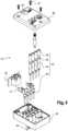
- the test plug 13comprises on the one hand a plurality of actuating elements 32 and a plurality of electrical conductors 33 configured so as to act on the internal electrical circuits of the base 10 in a manner causing the temporary action which was mentioned previously as long as the test plug 13 is plugged into the reception location 12 delimited by the base 10.
- the test plug 13further comprises an output socket 34 of the multi-contact type, contacts of which are respectively connected to all or part of the electrical conductors 33, the output socket 34 of the test plug 13 being configured so as to be able to be connected to a third connector (not shown) of the multi-contact type independent of the test block and the test plug 13 and contacts of which are electrically connected to the test equipment, in particular via a third multi-conductor cable (not shown).
- the test plug 13comprises a housing obtained by the assembly of a support 35 delimiting a cavity and a cover 36 closing this cavity.
- the output socket 34 of the test plug 13is housed in this cavity and opens outwards from the housing through an opening 42 formed in the cover 36.
- the cover 36is fixed to the support 35 by any conceivable mechanical means, such as for example by means of a plurality of screws 37.
- the cover 36is located on the front face of the test plug 13, the rear face 38 of which is intended to come against the front face of the base 10 (more precisely opposite the front cover 16) once the protective cover 11 has been removed.
- the actuating elements 32may consist of rods extending in projection from the rear face 38 of the test plug 13, outside the support 35, and capable of each being inserted into a through hole of the third row of through holes provided in the front cover 16. Their height is such that the total insertion of these rods obtained at the time of bringing the rear face 38 of the test plug 13 into contact with the base 10 causes the moving contacts 26 to move in opposition to the action of the pressure springs 27 and induces the opening of the internal electrical circuits whose moving contact 26 has been moved.
- some electrical conductors 33 of the test plug 13each comprise a pin 40 capable of projecting from the rear face 38 outside the support 35.
- Each pin 40is capable of being inserted into a through hole of the fourth row of through holes provided in the front cover 16 and of being plugged into one of the test pads 30 and is electrically connected to one of the contacts of the output socket 34 by means of a conductive wire 41.
- the test plug 13may also comprise a plurality of output sockets 44 each of the single-contact type and the other electrical conductors 33 of the test plug 13 each comprise a pin 43 extending projecting from the rear face 38 to the outside of the support 35.
- Each pin 43is adapted to be inserted into a through hole of the second row of through holes provided in the front cover 16 and to be plugged into one of the test pads 29 and is electrically connected to the single contact of one of the single-contact output sockets 44.
- An insulating cap 45is attached around a portion of the pin 43.
- the electrical conductors 33which are connected to the contacts of the output socket 34 of the test plug 13 are plugged into the test pads 30 via the pins 40 and are then electrically connected to all or part of the contacts of the output socket 18 of the base 10 of the test block by means of all or part of the internal electrical circuits, in particular via the second strips 25 and via the electrical conductors 24.
- the electrical conductors 33which are connected to the contacts of the output sockets 44 of the test plug 13 are plugged into the test pads 29 via the pins 43 and are then electrically connected to all or part of the contacts of the input socket 17 of the base 10 of the test block by means of all or part of the internal electrical circuits, in particular via the second strips 25 and via the electrical conductors 24. or part of the circuits internal electrical, in particular via the first strips 23 and via the electrical conductors 22.
- the actuating elements 32, the electrical conductors 33 and the organization of the internal electrical circuits of the base 10are organized so as to operate according to a short-circuited contact test principle.
- the internal electrical circuitis automatically short-circuited when the test plug 13 is inserted.
- the base 10ensures electrical continuity as long as the protective cover 11 is mounted on the base 10.
- the cover 11is removed.
- the pins 40, 43 of the test plug 13first come into contact with the test pads 29, 30 of the base 10 in order to establish the test circuit via the electrical conductors 33.
- test plug 13 and the base 10operate according to an open contact test principle (the internal electrical circuit is open when the protective cover 11 is removed and the device to be tested is then no longer powered) or according to a closed contact test principle (the electrical connection being permanent, the internal electrical circuit remains closed during the test).
- the output socket of the test plug 13is formed by a male or female connector of the RJ45 type comprising a pinout with 8 contact positions, each of the pins corresponding to a contact of the output socket of the test plug.
- the test apparatuscomprises the first connector previously mentioned, which is of the multi-contact type, independent of the test block and the test plug 13, complementary to the input socket 17 of the test block so as to be able to be connected to the input socket 17 of the test block and whose contacts are electrically connected to the power source, in particular via the first multi-conductor cable.
- the input socket 17 of the test block and the first connectorare configured so that the electrical connection between the internal electrical circuits of the test block and the power source results from the action of connecting the first connector with the input socket 17 of the test block.
- the first connectorcan in particular be of the RJ45 type and have a complementary nature to that of the input socket 17.
- the electrically conductive elements constituting the Faraday cageare connected to the shielding of the first multiconductor cable.
- the test apparatusalso comprises the second connector previously mentioned, which is of the multi-contact type, independent of the test block and the test plug 13, complementary to the output socket 18 of the test block so as to be able to be connected to the output socket 18 of the test block and whose contacts are electrically connected to the device to be tested, in particular via the second multi-conductor cable.
- the output socket 18 of the test block and the second connectorare configured so that the electrical connection between the internal electrical circuits and the device to be tested results from the action of connecting the second connector with the output socket 18 of the test block.
- the second connectormay in particular be of the RJ45 type and have a nature complementary to that of the output socket 18.
- the electrically conductive elements constituting the Faraday cageare connected to the shielding of the second multi-conductor cable.
- the test apparatusfinally comprises the third multi-contact type connector previously mentioned, which is independent of the test block and the test plug, complementary to the output socket 34 of the test plug 13 so as to be able to be connected to the output socket 34 of the test plug 13 and whose contacts are electrically connected to the test equipment, in particular via the third multi-conductor cable.
- the output socket 34 of the test plug 13 and the third connectorare configured so that the electrical connection of the electrical conductors 33 of the test plug 13 to the test equipment results from the action of connecting the third connector in the output socket 34 of the test plug 13.
- the third connectormay in particular be of the RJ45 type and have a nature complementary to that of the output socket 34.
- test block just describedis simple, robust, easy and practical to use and economical.
- the number of socketsis low and few electrical connectors need to be handled, which enhances its reliability by providing a small number of parts.
- the reliability and quality of measurements and calibrationsare very good, as is safety.
Landscapes
- Physics & Mathematics (AREA)
- General Physics & Mathematics (AREA)
- Engineering & Computer Science (AREA)
- Power Engineering (AREA)
- General Engineering & Computer Science (AREA)
- Microelectronics & Electronic Packaging (AREA)
- Electromagnetism (AREA)
- Measuring Leads Or Probes (AREA)
- Details Of Connecting Devices For Male And Female Coupling (AREA)
Description
Translated fromFrenchLa présente invention concerne un bloc d'essai destiné à être implanté dans le circuit raccordant un appareil à tester, notamment un compteur ou un relais de protection, et une source d'alimentation, notamment un capteur d'intensité et/ou un capteur de tension, alimentant l'appareil à tester, le bloc d'essai comprenant d'une part une embase comportant une pluralité de circuits électriques internes aptes à permettre la transmission d'informations de la source d'alimentation vers l'appareil à tester, d'autre part un couvercle de protection destiné à être assemblé avec l'embase de manière démontable pour former une enceinte fermée dans laquelle les circuits électriques internes sont logés, l'embase et le couvercle de protection étant configurés de sorte que le retrait du couvercle de protection donne accès à un emplacement d'accueil délimité par l'embase et apte à accueillir par enfichage une fiche de test indépendante du bloc d'essai et reliée électriquement à un équipement de test, notamment un voltmètre et/ou un ampèremètre et/ou une source fictive de courant.The present invention relates to a test block intended to be implanted in the circuit connecting a device to be tested, in particular a meter or a protection relay, and a power source, in particular a current sensor and/or a voltage sensor, supplying the device to be tested, the test block comprising on the one hand a base comprising a plurality of internal electrical circuits capable of allowing the transmission of information from the power source to the device to be tested, on the other hand a protective cover intended to be assembled with the base in a removable manner to form a closed enclosure in which the internal electrical circuits are housed, the base and the protective cover being configured such that the removal of the protective cover gives access to a reception location delimited by the base and capable of receiving by plugging in a test plug independent of the test block and electrically connected to a test equipment, in particular a voltmeter and/or an ammeter and/or a fictitious current source.
Depuis plusieurs décennies, il est connu d'implanter un appareil électrique connu sous le nom « bloc d'essai » ou « connecteur de test » dans le circuit électrique qui raccorde un appareil à tester à la source d'alimentation qui alimente l'appareil à tester. A titre d'exemple, la Demanderesse commercialise des blocs d'essai de cette nature sous la dénomination commerciale « Essailec ».For several decades, it has been known to implant an electrical device known as a "test block" or "test connector" in the electrical circuit that connects a device to be tested to the power source that supplies the device to be tested. For example, the Applicant markets test blocks of this nature under the trade name "Essailec".
Voir, par exemple, le document https://library.e.abb.com/public/ fc60562678a8db7ec1257cc400336fad/1SNC169001C0311_Gamme ESSAILECBIocs dessais.pdfSee, for example, the document https://library.e.abb.com/public/ fc60562678a8db7ec1257cc400336fad/1SNC169001C0311_Gamme ESSAILECBIocs dessais.pdf
Usuellement, la source d'alimentation peut comprendre un capteur de tension et/ou un capteur d'intensité associés à une phase déterminée d'un réseau électrique tandis que l'appareil à tester peut être un compteur ou un relais de protection destiné à piloter au moins un disjoncteur susceptible d'agir sur ladite phase en cas de surtension et/ou de surintensité détectées par la source d'alimentation et par le relais de protection.Usually, the power source may comprise a voltage sensor and/or a current sensor associated with a specific phase of an electrical network while the device to be tested may be a meter or a protection relay intended to control at least one circuit breaker capable of acting on said phase in the event of overvoltage and/or overcurrent detected by the power source and by the protection relay.
Classiquement, le bloc d'essai comprend une embase et un couvercle de protection assemblé sur l'embase de manière amovible pour délimiter une enceinte fermée et étanche selon la norme IP40 lorsque le couvercle est fixé sur l'embase. L'enceinte renferme et protège une pluralité de circuits électriques internes indépendants les uns des autres.Typically, the test block comprises a base and a protective cover assembled on the base in a removable manner to delimit a closed and sealed enclosure according to the IP40 standard when the cover is fixed on the base. The enclosure contains and protects a plurality of internal electrical circuits independent of each other.
Sur une face arrière et/ou sur une face latérale de l'embase, le bloc d'essai comprend une pluralité de prises d'entrée permettant de relier les circuits électriques internes à la source d'alimentation : chaque prise d'entrée est reliée à un unique circuit électrique interne déterminé et chaque circuit électrique interne est relié à une unique prise d'entrée. Il est nécessaire de connecter une pluralité de connecteurs dans les prises d'entrée et eux-mêmes reliés à la source d'alimentation par un câble comprenant une pluralité de brins conducteurs indépendants.On a rear face and/or on a side face of the base, the test block comprises a plurality of input sockets for connecting the circuits internal electrical to the power source: each input socket is connected to a single determined internal electrical circuit and each internal electrical circuit is connected to a single input socket. It is necessary to connect a plurality of connectors in the input sockets and themselves connected to the power source by a cable comprising a plurality of independent conductive strands.
Le bloc d'essai comprend également une pluralité de prises de sortie aménagées sur la face arrière et/ou sur une face latérale de l'embase. Ces prises de sortie permettent de relier les circuits électriques internes à l'appareil à tester selon une organisation dans laquelle chaque prise de sortie est reliée à un unique circuit électrique interne et chaque circuit électrique interne est relié à une unique prise de sortie. Il est nécessaire de connecter une pluralité de connecteurs dans les prises de sortie et eux-mêmes reliés à l'appareil à tester par un câble comprenant une pluralité de brins conducteurs indépendants.The test block also comprises a plurality of output sockets arranged on the rear face and/or on a side face of the base. These output sockets make it possible to connect the internal electrical circuits to the device to be tested according to an organization in which each output socket is connected to a single internal electrical circuit and each internal electrical circuit is connected to a single output socket. It is necessary to connect a plurality of connectors in the output sockets and themselves connected to the device to be tested by a cable comprising a plurality of independent conductive strands.
Le retrait du couvercle de protection, du côté de la face avant de l'embase, donne accès à un emplacement d'accueil délimité par l'embase et apte à accueillir, par enfichage, une fiche de test indépendante du bloc d'essai et reliée électriquement à un équipement de test. Usuellement, l'équipement de test peut comprendre un voltmètre et/ou un ampèremètre et/ou une source fictive de courant. L'enfichage de la fiche de test a pour effet d'agir temporairement sur l'état et/ou la configuration de tout ou partie des circuits électriques internes d'une manière prédéterminée, dépendant directement de la conception de la fiche de test, permettant de réaliser des opérations de mesure ou d'étalonnage relativement à l'appareil à tester par l'intermédiaire de l'équipement de test. La fiche de test comprend des éléments d'actionnement configurés à cet effet aptes à agir sur tout ou partie des circuits électriques internes de manière idoine en fonction de l'opération à réaliser.Removing the protective cover, on the front side of the base, provides access to a reception location delimited by the base and capable of receiving, by plugging in, a test plug independent of the test block and electrically connected to a test equipment. Usually, the test equipment may comprise a voltmeter and/or an ammeter and/or a dummy current source. Plugging in the test plug has the effect of temporarily acting on the state and/or configuration of all or part of the internal electrical circuits in a predetermined manner, directly dependent on the design of the test plug, making it possible to carry out measurement or calibration operations relative to the device to be tested via the test equipment. The test plug comprises actuating elements configured for this purpose capable of acting on all or part of the internal electrical circuits in a suitable manner depending on the operation to be carried out.
Si les solutions actuellement implémentées donnent satisfaction en termes d'efficacité et de robustesse, elles ne donnent pas une entière satisfaction malgré tout.Although the solutions currently implemented are satisfactory in terms of efficiency and robustness, they are not entirely satisfactory despite everything.
D'abord, il est nécessaire de raccorder chacune des prises d'entrée à la source d'alimentation et de raccorder chacune des prises de sortie à l'appareil à tester. Ces opérations sont par pratiques et éventuellement source d'erreur.First, it is necessary to connect each of the input jacks to the power source and connect each of the output jacks to the device under test. These operations are impractical and possibly error-prone.
Par ailleurs, la multiplication des moyens de connectique, entre les multiples prises d'entrée et de sortie et autant de connecteurs associés, rend l'ensemble complexe techniquement et perfectible en terme de coût. Il en résulte également une augmentation du facteur de pannes possibles ou de faux contacts qui dépend directement du nombre de pièces utilisées.Furthermore, the multiplication of means of connection, between the multiple input and output sockets and as many associated connectors, makes the whole thing technically complex and improvable in terms of cost. This results in also an increase in the factor of possible failures or false contacts which directly depends on the number of parts used.
La présente invention vise à résoudre tout ou partie des inconvénients listés ci-dessus.The present invention aims to resolve all or part of the drawbacks listed above.
Dans ce contexte, il existe un besoin de fournir un bloc d'essai qui soit simple, robuste, facile et pratique à utiliser et économique.In this context, there is a need to provide a test block that is simple, robust, easy and practical to use and economical.
A cet effet, il est proposé un bloc d'essai selon la revendication 1, destiné à être implanté dans le circuit raccordant un appareil à tester tel qu'un compteur ou un relais de protection et une source d'alimentation alimentant l'appareil à tester telle qu'un capteur d'intensité et/ou un capteur de tension, le bloc d'essai comprenant :
- une embase comportant une pluralité de circuits électriques internes aptes à permettre la transmission d'informations de la source d'alimentation vers l'appareil à tester,
- un couvercle de protection destiné à être assemblé avec l'embase de manière démontable pour former une enceinte fermée dans laquelle les circuits électriques internes sont logés,
- l'embase et le couvercle de protection étant configurés de sorte que le retrait du couvercle de protection donne accès à un emplacement d'accueil délimité par l'embase et apte à accueillir par enfichage une fiche de test indépendante du bloc d'essai et reliée électriquement à un équipement de test, notamment un voltmètre et/ou un ampèremètre et/ou une source fictive de courant,
- au moins une prise d'entrée de type multi-contact accessible depuis l'extérieur de l'enceinte et dont des contacts sont respectivement reliés électriquement aux circuits électriques internes de manière que la prise d'entrée est connectée à tous les circuits électriques internes en même temps, la prise d'entrée étant configurée de sorte à pouvoir être connectée à un premier connecteur de type multi-contact indépendant du bloc d'essai et dont des contacts sont reliés électriquement à la source d'alimentation, notamment via un câble multiconducteur,
- et au moins une prise de sortie de type multi-contact accessible depuis l'extérieur de l'enceinte et dont des contacts sont respectivement reliés électriquement aux circuits électriques internes de manière que la prise de sortie est connectée à tous les circuits électriques internes en même temps, la prise de sortie étant configurée de sorte à pouvoir être connectée à un deuxième connecteur de type multi-contact indépendant du bloc d'essai et dont des contacts sont reliés électriquement à l'appareil à tester, notamment via un câble multiconducteur.
- a base comprising a plurality of internal electrical circuits capable of allowing the transmission of information from the power source to the device to be tested,
- a protective cover intended to be assembled with the base in a removable manner to form a closed enclosure in which the internal electrical circuits are housed,
- the base and the protective cover being configured so that removal of the protective cover gives access to a reception location delimited by the base and capable of accommodating by plugging in a test plug independent of the test block and electrically connected to test equipment, in particular a voltmeter and/or an ammeter and/or a fictitious current source,
- at least one multi-contact type input socket accessible from outside the enclosure and whose contacts are respectively electrically connected to the internal electrical circuits so that the input socket is connected to all the internal electrical circuits at the same time, the input socket being configured so as to be able to be connected to a first multi-contact type connector independent of the test block and whose contacts are electrically connected to the power source, in particular via a multi-conductor cable,
- and at least one multi-contact type output socket accessible from outside the enclosure and whose contacts are respectively electrically connected to the internal electrical circuits so that the output socket is connected to all the internal electrical circuits at the same time, the output socket being configured so as to be able to be connected to a second connector of the type multi-contact independent of the test block and whose contacts are electrically connected to the device to be tested, in particular via a multi-conductor cable.
L'embase et le couvercle de protection comprennent des éléments électriquement conducteurs reliés entre eux et configurés de sorte assurer une continuité et une fermeture de blindage magnétique telles que l'enceinte délimitée par l'embase et le couvercle de protection est une cage de Faraday protégeant les circuits électriques internes par rapport aux champs magnétiques extérieurs à l'enceinte délimitée par l'embase et le couvercle de protection.The base and the protective cover comprise electrically conductive elements connected together and configured so as to provide continuity and magnetic shielding closure such that the enclosure delimited by the base and the protective cover is a Faraday cage protecting the internal electrical circuits from magnetic fields external to the enclosure delimited by the base and the protective cover.
L'embase comprend un capot amovible dont le retrait par rapport au reste de l'embase donne un accès aux circuits électriques internes et dont la nature et/ou la forme est adaptée à la nature des prises d'entrée et de sortie.The base includes a removable cover, the removal of which from the rest of the base provides access to the internal electrical circuits and the nature and/or shape of which is adapted to the nature of the input and output sockets.
Il est également proposé un appareillage d'essai comprenant un tel bloc d'essai et une fiche de test apte à s'enficher dans l'emplacement d'accueil délimité par l'embase après le retrait du couvercle de protection, les circuits électriques internes du bloc d'essai et la fiche de test étant configurés de sorte que l'enfichage de la fiche de test provoque une action temporaire sur tout ou partie des circuits électriques internes du bloc d'essai tant que la fiche de test est enfichée, ladite action temporaire étant telle qu'elle permet de réaliser des opérations de mesure et/ou d'étalonnage vis-à-vis de l'appareil à tester grâce à l'équipement de test.There is also provided a test apparatus comprising such a test block and a test plug capable of being plugged into the receiving location delimited by the base after removal of the protective cover, the internal electrical circuits of the test block and the test plug being configured such that the plugging in of the test plug causes a temporary action on all or part of the internal electrical circuits of the test block as long as the test plug is plugged in, said temporary action being such that it allows measurement and/or calibration operations to be carried out with respect to the device to be tested using the test equipment.
Selon un mode de réalisation particulier, l'appareillage d'essai comprend un premier connecteur de type multi-contact indépendant du bloc d'essai et de la fiche de test, complémentaire de la prise d'entrée du bloc d'essai de sorte à pouvoir être connecté à la prise d'entrée du bloc d'essai et dont des contacts sont reliés électriquement à la source d'alimentation, notamment via un câble multiconducteur et la prise d'entrée du bloc d'essai et le premier connecteur sont configurés de sorte que la connexion électrique entre les circuits électriques internes du bloc d'essai et la source d'alimentation résulte de l'action de connexion du premier connecteur avec la prise d'entrée du bloc d'essai.According to a particular embodiment, the test apparatus comprises a first multi-contact type connector independent of the test block and the test plug, complementary to the input socket of the test block so as to be able to be connected to the input socket of the test block and whose contacts are electrically connected to the power source, in particular via a multi-conductor cable and the input socket of the test block and the first connector are configured so that the electrical connection between the internal electrical circuits of the test block and the power source results from the action of connecting the first connector with the input socket of the test block.
L'appareillage d'essai comprend de préférence un deuxième connecteur de type multi-contact indépendant du bloc d'essai et de la fiche de test, complémentaire de la prise de sortie du bloc d'essai de sorte à pouvoir être connecté à la prise de sortie du bloc d'essai et dont des contacts sont reliés électriquement à l'appareil à tester, notamment via un câble multiconducteur et la prise de sortie du bloc d'essai et le deuxième connecteur sont configurés de sorte que la connexion électrique entre les circuits électriques internes et l'appareil à tester résulte de l'action de connexion du deuxième connecteur avec la prise de sortie du bloc d'essai.The test apparatus preferably comprises a second multi-contact type connector independent of the test block and the test plug, complementary to the output socket of the test block so as to be connectable to the output socket of the test block and whose contacts are electrically connected to the device to be tested, in particular via a multi-conductor cable and the output socket of the test block and the second connector are configured so that the connection electrical current between the internal electrical circuits and the device under test results from the action of connecting the second connector with the output jack of the test block.
De préférence, la fiche de test comprend d'une part une pluralité d'éléments d'actionnement et une pluralité de conducteurs électriques configurés de sorte à agir sur les circuits électriques internes de l'embase d'une manière provoquant ladite action temporaire tant que la fiche de test est enfichée dans l'emplacement d'accueil délimité par l'embase et d'autre part une prise de sortie de type multi-contact dont des contacts sont respectivement connectés à tout ou partie des conducteurs électriques de la fiche de test, la prise de sortie de la fiche de test étant configurée de sorte à pouvoir être connectée à un troisième connecteur de type multi-contact indépendant du bloc d'essai et de la fiche de test et dont des contacts sont reliés électriquement à l'équipement de test, notamment via un câble multiconducteur.Preferably, the test plug comprises on the one hand a plurality of actuating elements and a plurality of electrical conductors configured so as to act on the internal electrical circuits of the base in a manner causing said temporary action as long as the test plug is plugged into the docking location delimited by the base and on the other hand a multi-contact type output socket, contacts of which are respectively connected to all or part of the electrical conductors of the test plug, the output socket of the test plug being configured so as to be able to be connected to a third multi-contact type connector independent of the test block and the test plug and contacts of which are electrically connected to the test equipment, in particular via a multi-conductor cable.
L'appareillage d'essai peut être configuré de sorte que lorsque la fiche de test est enfichée dans l'emplacement d'accueil délimité par l'embase, les conducteurs électriques qui sont connectés aux contacts de la prise de sortie de la fiche de test sont reliés électriquement à tout ou partie des contacts de la prise de sortie de l'embase du bloc d'essai par l'intermédiaire de tout ou partie des circuits électriques internes.The test apparatus may be configured so that when the test plug is inserted into the docking location defined by the base, the electrical conductors that are connected to the test plug output socket contacts are electrically connected to some or all of the test block output socket contacts through some or all of the internal electrical circuits.
La prise de sortie de la fiche de test est notamment formée par un connecteur mâle ou femelle de type RJ45 comprenant un brochage à 8 positions de contact, chacune des broches correspondant à un contact de la prise de sortie de la fiche de test.The output socket of the test plug is notably formed by a male or female RJ45 type connector comprising a pinout with 8 contact positions, each of the pins corresponding to a contact of the output socket of the test plug.
Selon un mode de réalisation particulier, l'appareillage d'essai comprend le troisième connecteur de type multi-contact indépendant du bloc d'essai et de la fiche de test, complémentaire de la prise de sortie de la fiche de test de sorte à pouvoir être connecté à la prise de sortie de la fiche de test et dont des contacts sont reliés électriquement à l'équipement de test, notamment via un câble multiconducteur et la prise de sortie de la fiche de test et le troisième connecteur sont configurés de sorte que la connexion électrique des conducteurs électriques de la fiche de test à l'équipement de test résulte de l'action de connexion du troisième connecteur dans la prise de sortie de la fiche de test.According to a particular embodiment, the test apparatus comprises the third multi-contact type connector independent of the test block and the test plug, complementary to the output socket of the test plug so as to be connectable to the output socket of the test plug and whose contacts are electrically connected to the test equipment, in particular via a multi-conductor cable and the output socket of the test plug and the third connector are configured so that the electrical connection of the electrical conductors of the test plug to the test equipment results from the connection action of the third connector in the output socket of the test plug.
L'invention sera bien comprise à l'aide de la description qui suit de modes particuliers de réalisation de l'invention donnés à titre d'exemples non limitatifs et représentés sur les dessins annexés, dans lesquels :
- Les
Figures 1 à 3 sont des vues en perspective d'un exemple d'appareillage d'essai selon l'invention, respectivement sensiblement de dessus, de face et sensiblement de dessous. - La
Figure 4 est une vue en éclaté de l'embase du bloc d'essai desFigures 1 à 3 . - La
Figure 5 est une vue en éclaté de la fiche de test visibles sur lesFigures 1 à 3 .
- THE
Figures 1 to 3 are perspective views of an example of test apparatus according to the invention, respectively substantially from above, from the front and substantially from below. - There
Figure 4 is an exploded view of the test block base of theFigures 1 to 3 . - There
Figure 5 is an exploded view of the test sheet visible on theFigures 1 to 3 .
En référence aux
La source d'alimentation peut comprendre un capteur de tension et/ou un capteur d'intensité associés à une phase déterminée d'un réseau électrique tandis que l'appareil à tester peut être un compteur ou un relais de protection destiné à piloter au moins un disjoncteur susceptible d'agir sur cette phase en cas de surtension et/ou de surintensité détectées par la source d'alimentation et par le relais de protection.The power source may comprise a voltage sensor and/or a current sensor associated with a specific phase of an electrical network, while the device to be tested may be a meter or a protection relay intended to control at least one circuit breaker capable of acting on this phase in the event of an overvoltage and/or overcurrent detected by the power source and by the protection relay.
Le bloc d'essai comprend une embase 10 comportant une pluralité de circuits électriques internes indépendants les uns des autres et permettant la transmission d'informations de la source d'alimentation vers l'appareil à tester.The test block comprises a
Les circuits électriques internes sont destinés à véhiculer des informations distinctes d'un circuit électrique interne à l'autre et représentatives, au niveau de chaque circuit électrique interne, d'une grandeur physique correspondante issue de la source d'alimentation et à transmettre à l'appareil à tester lorsque les circuits électriques internes sont fermés. La nature et l'organisation des circuits électriques internes peuvent être quelconques et ne sont pas limitatives en soi. Un exemple de réalisation particulier mais en aucun cas limitatif sera décrit plus loin.The internal electrical circuits are intended to convey information that is distinct from one internal electrical circuit to another and representative, at the level of each internal electrical circuit, of a corresponding physical quantity from the power source and to be transmitted to the device to be tested when the internal electrical circuits are closed. The nature and organization of the internal electrical circuits may be arbitrary and are not limiting in themselves. A particular but in no way limiting example of an embodiment will be described later.
Par exemple, il est possible de prévoir que deux circuits électriques internes permettent la transmission de la valeur mesurée de la tension électrique d'une phase d'un réseau électrique lorsque la source d'alimentation comprend un capteur de tension associé à cette phase, jusqu'à un relais de protection lorsque l'appareil à tester comprend un tel relais de protection, susceptible d'actionner un disjoncteur placé sur cette phase en cas de surtension. Toujours à titre d'exemple, il est possible de prévoir que deux autres circuits électriques internes permettent la transmission de la valeur mesurée de l'intensité électrique d'une phase du réseau électrique lorsque la source d'alimentation comprend un capteur d'intensité associé à cette phase, jusqu'à un relais de protection lorsque l'appareil à tester comprend un tel relais de protection, susceptible d'actionner un disjoncteur placé sur cette phase en cas de surintensité.For example, it is possible to provide that two internal electrical circuits allow the transmission of the measured value of the electrical voltage of a phase of an electrical network when the power source comprises a voltage sensor associated with this phase, to a protection relay when the device to be tested comprises such a protection relay, capable of actuating a circuit breaker placed on this phase in the event of an overvoltage. Still by way of example, it is possible to provide that two other internal electrical circuits allow the transmission of the measured value of the electrical intensity of a phase of the network electrical when the power source includes a current sensor associated with this phase, up to a protection relay when the device to be tested includes such a protection relay, capable of actuating a circuit breaker placed on this phase in the event of overcurrent.
Le bloc d'essai comprend aussi un couvercle de protection 11 destiné à être assemblé avec l'embase 10 de manière démontable pour former une enceinte fermée dans laquelle les circuits électriques internes sont logés.The test block also includes a
Pour cela, de la manière représentée, l'embase 10 peut comprendre un boitier 15 qui délimite une cavité ouverte dans laquelle les circuits électriques internes sont implantés et le couvercle de protection 11 ferme de manière étanche cette cavité lorsqu'il est monté sur l'embase 10, en particulier sur le boitier 15.For this, in the manner shown, the
Il peut avantageusement être fait en sorte que l'enceinte délimitée par l'embase 10 et le couvercle de protection 11 soit étanche. L'étanchéité de l'enceinte conférée par l'embase 10 et le couvercle de protection 11 respecte notamment la norme IP40 lorsque le couvercle 11 est fixé sur l'embase 10. L'embase 10 et le couvercle de protection 11 comprennent tous les moyens nécessaires pour assurer cette fonction.It may advantageously be ensured that the enclosure delimited by the
L'embase 10 et le couvercle de protection 11 sont configurés de sorte que le retrait du couvercle de protection 11 donne accès à un emplacement d'accueil 12 délimité par l'embase 10 et apte à accueillir, par enfichage, une fiche de test 13 indépendante du bloc d'essai et reliée électriquement à un équipement de test (non représenté). En fonction de la nature du test à réaliser, l'équipement de test peut comprendre un voltmètre et/ou un ampèremètre et/ou une source fictive de courant.The
Sur les
L'invention concerne également un appareillage d'essai comprenant un tel bloc d'essai mais également la fiche de test 13 qui est apte à s'enficher dans l'emplacement d'accueil 12 délimité par l'embase 10 après le retrait du couvercle de protection 11.The invention also relates to a test apparatus comprising such a test block but also the
L'embase 10 est destinée à être fixée sur une armoire électrique. Le couverle de protection 11 définit une face avant du bloc d'essai lorsqu'il est monté sur l'embase 10 en ce sens qu'il est accessible depuis l'extérieur de l'armoire électrique lorsque le bloc d'essai est monté sur l'armoire électrique. L'embase 10 du bloc d'essai comprend des éléments de montage 14 permettant de fixer le bloc d'essai sur l'armoire métallique, par exemple, comme cela est représenté, une pluralité de pattes de retenue dont chacune peut être serrée par une vis dédiée à cette opération.The
La face avant de l'embase 10, lorsque le couvercle de protection 11 est retiré, est constituée par un couvercle avant 16 muni d'une pluralité de rangées de trous traversants. Le couvercle avant 16 est fixé sur le boitier 15 par tout moyen adapté, notamment de type par encliquetage.The front face of the
L'embase 10 du bloc d'essai comprend au moins une prise d'entrée 17 de type multi-contact accessible depuis l'extérieur de l'enceinte et dont des contacts sont respectivement reliés électriquement aux circuits électriques internes de manière que la prise d'entrée 17 est connectée à tous les circuits électriques internes en même temps. La prise d'entrée 17 est configurée de sorte à pouvoir être connectée à un premier connecteur (non représenté) de type multi-contact indépendant du bloc d'essai et dont des contacts sont reliés électriquement à la source d'alimentation, notamment via un premier câble multiconducteur (non représenté).The
L'embase 10 du bloc d'essai comprend également au moins une prise de sortie 18 de type multi-contact accessible depuis l'extérieur de l'enceinte et dont des contacts sont respectivement reliés électriquement aux circuits électriques internes de manière que la prise de sortie 18 est connectée à tous les circuits électriques internes en même temps. La prise de sortie 18 est configurée de sorte à pouvoir être connectée à un deuxième connecteur (non représenté) de type multi-contact indépendant du bloc d'essai et dont des contacts sont reliés électriquement à l'appareil à tester, notamment via un deuxième câble multiconducteur (non représenté).The
Pour la prise d'entrée 17 et pour la prise de sortie 18, chaque contact de la prise considérée est relié à un seul circuit électrique interne et chaque circuit électrique interne est relié à un seul contact de cette prise. Ainsi, chaque circuit électrique interne du bloc d'essai est apte à relier électriquement, lorsque ce circuit électrique interne est fermé, un unique contact de la prise d'entrée 17 à un unique contact de la prise de sortie 18.For the
La connexion électrique entre les contacts des prises d'entrée 17 et de sortie 18 avec les circuits électriques internes du bloc d'essai peut se faire au niveau d'un circuit imprimé 19, connu sous l'acronyme « PCB » pour « Printed Circuit Board » en terminologie anglo-saxonne. La nature du circuit imprimé 19 dépend notamment de la nature des prises 17, 18 et de la nature des circuits électriques internes.The electrical connection between the contacts of the
Dans ce document, le terme « multiconducteur » signifie notamment que le câble concerné comprend une pluralité de conducteurs électriques isolés individuellement, et donc isolés les uns des autres. Le terme « multi-contact » signifie que la prise 17, 18 ou le connecteur avec qui la prise 17, 18 coopère comprend une pluralité de contacts électriques isolés individuellement, et donc isolés les uns des autres.In this document, the term "multi-conductor" means in particular that the cable concerned comprises a plurality of insulated electrical conductors. individually, and therefore isolated from each other. The term “multi-contact” means that the
Selon un mode de réalisation particulier donnant une entière satisfaction, la prise d'entrée 17 et la prise de sortie 18 sont chacune formées par un connecteur mâle ou femelle de type RJ45, dont un autre nom usuel est 8P8C (8 positions et 8 contacts électriques), comprenant un brochage à 8 positions de contact, chacune des broches correspondant à un contact de la prise 17, 18 concernée.According to a particular embodiment giving complete satisfaction, the
Cette caractéristique, bien qu'avantageuse et efficace, n'est pas limitative. Les moyens utilisés pour parvenir à la fonction présentée ci-dessus pour les prises 17, 18 peuvent être quelconques. Il est par exemple possible de prévoir que la prise d'entrée 17 et la prise de sortie 18 soient chacune formées par un connecteur mâle ou femelle de type USB pour « Universal Serial Bus » en terminologie anglo-saxonne.This feature, although advantageous and effective, is not limiting. The means used to achieve the function presented above for the
L'embase 10 et le couvercle de protection 11 comprennent également des éléments électriquement conducteurs reliés entre eux et configurés de sorte assurer une continuité et une fermeture de blindage magnétique telles que l'enceinte délimitée par l'embase 10 et le couvercle de protection 11 est une cage de Faraday protégeant les circuits électriques internes vis-à-vis des champs magnétiques extérieurs à l'enceinte délimitée par l'embase 10 et le couvercle de protection 11.The
L'embase 10 comprend un capot amovible 20 dont le retrait par rapport au reste de l'embase 10 donne un accès aux circuits électriques internes et dont la nature et/ou la forme est adaptée à la nature des prises d'entrée et de sortie 17, 18. La fixation du capot amovible 20 avec le boitier 15 peut se faire par exemple par l'intermédiaire de vis 21. Un autre avantage est de pouvoir adapter le capot amovible 20 en fonction de la nature des prises d'entrée et de sortie 17, 18 et du circuit imprimé 19 tout en utilisant un boitier 15 commun aux différentes variantes d'embases 10 ainsi obtenues par remplacement ou substitution des prises d'entrée et de sortie 17, 18, du capot amovible 20 et du circuit imprimé 19.The
Le capot amovible 20 comprend donc une partie des éléments électriquement conducteurs constitutifs de la cage de Faraday. Il en est de même pour le boitier 15 et pour le couvercle de protection 11.The
Le capot amovible 20 vient se fixer sur le boitier 15 de sorte à définir la face arrière de l'embase 10, c'est-à-dire la face opposée à la face avant recevant le couvercle de protection 11 et destinée à être tournée vers l'intérieur de l'armoire électrique. Le capot amovible 20 comprend des ouvertures permettant à la prise d'entrée 17 et à la prise de sortie 18 d'être accessible depuis l'extérieur du bloc d'essai du côté de la face arrière de l'embase 10. Il reste toutefois possible d'envisager que la prise d'entrée 17 et/ou la prise de sortie 18 puisse déboucher vers l'extérieur de l'embase 10 au niveau d'une face latérale de l'embase 10, c'est-à-dire une face latérale du boitier 15 qui rejoint le capot amovible 20 au couvercle de protection 11.The
Par ailleurs, le bloc d'essai comprend des éléments électriquement conducteurs (non représentés) reliant les éléments électriquement conducteurs constitutifs de la cage de Faraday à l'armoire métallique lorsque l'embase 10 est montée sur l'armoire électrique via les éléments de montage 14. Ainsi, la cage de Faraday est électriquement reliée au métal de l'armoire métallique.Furthermore, the test block includes electrically conductive elements (not shown) connecting the electrically conductive elements constituting the Faraday cage to the metal cabinet when the
Selon un mode de réalisation particulier, sur tout ou partie de la surface des parois extérieures de l'embase 10, ces parois extérieures sont recouvertes intérieurement et/ou extérieurement, ou constituées, par au moins un panneau d'aluminiumAccording to a particular embodiment, on all or part of the surface of the external walls of the
A titre d'exemple, les parois extérieures de l'embase 10 sont recouvertes extérieurement ou constituées par de l'aluminium formant un panneau continu fermé. Par exemple, il est possible de prévoir que 5 des 6 parois du boitier 15 soient recouvertes d'aluminium de façon que le capot vienne fermer le parallélépipède d'aluminium de la cage de Faraday.For example, the outer walls of the base 10 are externally covered or made of aluminum forming a closed continuous panel. For example, it is possible to provide that 5 of the 6 walls of the
En particulier, sur tout ou partie de la surface des parois extérieures du capot amovible 20, ces parois extérieures sont recouvertes intérieurement et/ou extérieurement, ou constituées, par au moins un panneau d'aluminium.In particular, over all or part of the surface of the outer walls of the
A titre d'exemple, les parois extérieures du capot 20 sont recouvertes extérieurement ou constituées par de l'aluminium formant un panneau continu fermé. Notamment, la face extérieure et/ou la face intérieure de la paroi principale extérieure du capot amovible sont recouvertes d'aluminium, en sachant que les 4 faces de la tranche sont également avec de l'aluminium.For example, the outer walls of the
Parallèlement, sur tout ou partie de la surface des parois extérieures du couvercle de protection 11, ces parois extérieures sont recouvertes intérieurement et/ou extérieurement, ou constituées, par au moins un panneau d'aluminium.At the same time, over all or part of the surface of the outer walls of the
A titre d'exemple, les parois extérieures du couvercle de protection 11 sont recouvertes intérieurement par un panneau d'aluminium monobloc 39 (visible sur la
Il est compris que les panneaux d'aluminium présents au niveau de l'embase 10 et au niveau du capot de protection 11 sont tous raccordés entre eux de sorte à former la cage de Faraday.It is understood that the aluminum panels present at the
Les circuits électriques internes du bloc d'essai et la fiche de test 13 sont configurés de sorte que l'enfichage de la fiche de test 13 provoque une action temporaire sur tout ou partie des circuits électriques internes du bloc d'essai tant que la fiche de test 13 est enfichée, cette action temporaire étant telle qu'elle permet de réaliser des opérations de mesure et/ou d'étalonnage vis-à-vis de l'appareil à tester grâce à l'équipement de test.The internal electrical circuits of the test block and the
Selon un mode de réalisation tel que représenté sur la
Selon ce montage, chaque circuit électrique interne est fermé tant que le contact mobile 26 est en contact des deux barrettes 23, 25 sous l'effet du ressort 27. Ceci correspond à la configuration naturellement occupée tant que la fiche de test 13 n'est pas enfichée dans l'emplacement d'accueil 12 délimité par l'embase 10. Par contre, un déplacement forcé du contact mobile 26 en opposition à l'action du ressort 27 provoque l'ouverture du circuit électrique interne, en ce sens que ce déplacement du contact mobile 26 induit que les deux barrettes de contact 23, 25 ne sont plus en contact électrique direct.According to this assembly, each internal electrical circuit is closed as long as the
La première barrette de contact 23 comprend un plot de test 29 et la deuxième barrette de contact 25 comprend un plot de test 30, dont le fonctionnement sera expliqué plus loin. Chaque plot de test 29, 30 comprend un ressort de contact 31.The
Tous les circuits électrique internes ainsi constitués sont logés dans le boitier 15 de l'embase 10 et le couvercle avant 16 vient recouvrir et protéger les composants des circuits électriques internes.All the internal electrical circuits thus constituted are housed in the
Le couvercle avant 16 comprend :
- une première rangée de trous traversants, dont chaque trou traversant est situé à l'aplomb de l'une des premières barrettes de
contact 23, - une deuxième rangée de trous traversants, dont chaque trou traversant est situé à l'aplomb de l'un des plots
de test 29, - une troisième rangée de trous traversants, dont chaque trou traversant est situé à l'aplomb de l'un des
contacts mobiles 26, - une quatrième rangée de trous traversants, dont chaque trou traversant est situé à l'aplomb de l'un des plots
de test 30, - et une cinquième rangée de trous traversants, dont chaque trou traversant est situé à l'aplomb de l'une des deuxièmes barrettes de
contact 25.
- a first row of through holes, each through hole of which is located directly above one of the first contact strips 23,
- a second row of through holes, each through hole of which is located directly above one of the
test pads 29, - a third row of through holes, each through hole of which is located directly above one of the
movable contacts 26, - a fourth row of through holes, each through hole of which is located directly above one of the
test pads 30, - and a fifth row of through holes, each through hole of which is located directly above one of the second contact strips 25.
Selon un mode de réalisation particulier et en référence maintenant aux
La fiche de test 13 comprend d'autre part une prise de sortie 34 de type multi-contact dont des contacts sont respectivement connectés à tout ou partie des conducteurs électriques 33, la prise de sortie 34 de la fiche de test 13 étant configurée de sorte à pouvoir être connectée à un troisième connecteur (non représenté) de type multi-contact indépendant du bloc d'essai et de la fiche de test 13 et dont des contacts sont reliés électriquement à l'équipement de test, notamment via un troisième câble multiconducteur (non représenté).The test plug 13 further comprises an
Selon un mode de réalisation particulier, la fiche de test 13 comprend un boitier obtenu par la réunion d'un support 35 délimitant une cavité et d'un capot 36 refermant cette cavité. La prise de sortie 34 de la fiche de test 13 est logée dans cette cavité et débouche vers l'extérieur du boitier au travers d'une ouverture 42 ménagée dans le capot 36. Le capot 36 est fixé sur le support 35 par tout moyen mécanique envisageable, comme par exemple par l'intermédiaire d'une pluralité de vis 37. Le capot 36 est situé sur la face avant de la fiche de test 13 dont la face arrière 38 est destinée à venir contre la face avant de l'embase 10 (plus précisément en regard du couvercle avant 16) une fois que le couvercle de protection 11 a été retiré.According to a particular embodiment, the
Il est précisé ici que les éléments d'actionnement 32 peuvent être constitués par des tiges s'étendant en saillie depuis la face arrière 38 de la fiche de test 13, à l'extérieur du support 35, et aptes à s'insérer chacune dans un trou traversant de la troisième rangée de trous traversants ménagés dans le couvercle avant 16. Leur hauteur est telle que l'insertion totale de ces tiges obtenue au moment de la mise en contact de la face arrière 38 de la fiche de test 13 contre l'embase 10 provoque le déplacement des contacts mobiles 26 en opposition à l'action des ressorts de pression 27 et induit l'ouverture des circuits électriques internes dont le contact mobile 26 a été déplacé.It is specified here that the
Comme cela est représenté sur la
En plus de la prise de sortie 34 de type multicontact, la fiche de test 13 peut également comprendre une pluralité de prises de sortie 44 chacune de type monocontact et les autres conducteurs électriques 33 de la fiche de test 13 comprennent chacun une broche 43 s'étendant en saillie de la face arrière 38 à l'extérieur du support 35. Chaque broche 43 est apte à s'insérer dans un trou traversant de la deuxième rangée de trous traversants ménagés dans le couvercle avant 16 et à venir s'enficher dans l'un des plots de test 29 et est reliée électriquement au contact unique de l'une des prises de sortie 44 monocontact. Un capuchon isolant 45 est rapporté autour d'une partie de la broche 43.In addition to the multi-contact
Lorsque la fiche de test 13 est enfichée dans l'emplacement d'accueil 12 délimité par l'embase 10, les conducteurs électriques 33 qui sont connectés aux contacts de la prise de sortie 34 de la fiche de test 13 viennent s'enficher dans les plots de test 30 via les broches 40 et sont alors reliés électriquement à tout ou partie des contacts de la prise de sortie 18 de l'embase 10 du bloc d'essai par l'intermédiaire de tout ou partie des circuits électriques internes, notamment via les deuxièmes barrettes 25 et via les conducteurs électriques 24. Dans le même temps, les conducteurs électriques 33 qui sont connectés aux contacts des prises de sortie 44 de la fiche de test 13 viennent s'enficher dans les plots de test 29 via les broches 43 et sont alors reliés électriquement à tout ou partie des contacts de la prise d'entrée 17 de l'embase 10 du bloc d'essai par l'intermédiaire de tout ou partie des circuits électriques internes, notamment via les les premières barrettes 23 et via les conducteurs électriques 22.When the
Dans l'exemple illustré, les éléments d'actionnement 32, les conducteurs électriques 33 et l'organisation des circuits électriques internes de l'embase 10 sont organisés de sorte à fonctionner selon un principe de test à contacts courts-circuités. Ainsi, le circuit électrique interne est court-circuité automatiquement à l'enfichage de la fiche de test 13. En fonctionnement normal, l'embase 10 assure la continuité électrique tant que le couvercle de protection 11 est monté sur l'embase 10. Au moment du test, le couvercle 11 est retiré. Au moment de l'enfichage de la fiche de test 13, les broches 40, 43 de la fiche de test 13 viennent d'abord en contact avec les plots de test 29, 30 de l'embase 10 afin d'établir le circuit de test via les conducteurs électriques 33. Ce n'est qu'une fois la fiche de test 13 complètement insérée dans l'embase 10 que le contact mobile 26 ouvre le contact entre les barrettes de contact 23, 25 afin de dériver entièrement le courant via les conducteurs électriques 33. Au moment de la remise en service à l'issue du test, grâce au contact mobile 26 sollicité par le ressort de pression 27, le circuit électrique interne se referme automatiquement quand la fiche de test 13 est déconnectée hors de l'embase 10.In the illustrated example, the
Cette caractéristique n'est toutefois pas limitative et il est possible de prévoir une organisation de la fiche de test 13 et de l'embase 10 telle qu'elles fonctionnent selon un principe de test à contacts ouverts (le circuit électrique interne est ouvert lorsque le couvercle de protection 11 est enlevé et l'appareil à tester n'est alors plus alimenté) ou selon un principe de test à contacts fermés (la connexion électrique étant permanente, le circuit électrique interne reste fermé durant le test).This characteristic is however not limiting and it is possible to provide an organization of the
La prise de sortie de la fiche de test 13 est formée par un connecteur mâle ou femelle de type RJ45 comprenant un brochage à 8 positions de contact, chacune des broches correspondant à un contact de la prise de sortie de la fiche de test.The output socket of the
L'appareillage d'essai comprend le premier connecteur précédemment évoqué, qui est de type multi-contact, indépendant du bloc d'essai et de la fiche de test 13, complémentaire de la prise d'entrée 17 du bloc d'essai de sorte à pouvoir être connecté à la prise d'entrée 17 du bloc d'essai et dont des contacts sont reliés électriquement à la source d'alimentation, notamment via le premier câble multiconducteur. La prise d'entrée 17 du bloc d'essai et le premier connecteur sont configurés de sorte que la connexion électrique entre les circuits électriques internes du bloc d'essai et la source d'alimentation résulte de l'action de connexion du premier connecteur avec la prise d'entrée 17 du bloc d'essai. Le premier connecteur peut notamment être de type RJ45 et présenter une nature complémentaire de celle de la prise d'entrée 17.The test apparatus comprises the first connector previously mentioned, which is of the multi-contact type, independent of the test block and the
Selon un mode de réalisation particulier, les éléments électriquement conducteurs constitutifs de la cage de Faraday sont reliés au blindage du premier câble multiconducteur.According to a particular embodiment, the electrically conductive elements constituting the Faraday cage are connected to the shielding of the first multiconductor cable.
L'appareillage d'essai comprend également le deuxième connecteur précédemment évoqué, qui est de type multi-contact, indépendant du bloc d'essai et de la fiche de test 13, complémentaire de la prise de sortie 18 du bloc d'essai de sorte à pouvoir être connecté à la prise de sortie 18 du bloc d'essai et dont des contacts sont reliés électriquement à l'appareil à tester, notamment via le deuxième câble multiconducteur. La prise de sortie 18 du bloc d'essai et le deuxième connecteur sont configurés de sorte que la connexion électrique entre les circuits électriques internes et l'appareil à tester résulte de l'action de connexion du deuxième connecteur avec la prise de sortie 18 du bloc d'essai. Le deuxième connecteur peut notamment être de type RJ45 et présenter une nature complémentaire de celle de la prise de sortie 18.The test apparatus also comprises the second connector previously mentioned, which is of the multi-contact type, independent of the test block and the
Avantageusement, les éléments électriquement conducteurs constitutifs de la cage de Faraday sont reliés au blindage du deuxième câble multiconducteur.Advantageously, the electrically conductive elements constituting the Faraday cage are connected to the shielding of the second multi-conductor cable.
L'appareillage d'essai comprend enfin le troisième connecteur de type multi-contact précédemment évoqué, qui est indépendant du bloc d'essai et de la fiche de test, complémentaire de la prise de sortie 34 de la fiche de test 13 de sorte à pouvoir être connecté à la prise de sortie 34 de la fiche de test 13 et dont des contacts sont reliés électriquement à l'équipement de test, notamment via le troisième câble multiconducteur. La prise de sortie 34 de la fiche de test 13 et le troisième connecteur sont configurés de sorte que la connexion électrique des conducteurs électriques 33 de la fiche de test 13 à l'équipement de test résulte de l'action de connexion du troisième connecteur dans la prise de sortie 34 de la fiche de test 13. Le troisième connecteur peut notamment être de type RJ45 et présenter une nature complémentaire de celle de la prise de sortie 34.The test apparatus finally comprises the third multi-contact type connector previously mentioned, which is independent of the test block and the test plug, complementary to the
Le bloc d'essai qui vient d'être décrit est simple, robuste, facile et pratique à utiliser et économique. Le nombre de prises est peu élevé et il est nécessaire de manipuler peu de connecteurs électriques, ce qui renforce sa fiabilité en prévoyant un nombre de pièces restreint. Par ailleurs, la fiabilité et la qualité des mesures et des étalonnages sont très bonnes, de même que la sécurité.The test block just described is simple, robust, easy and practical to use and economical. The number of sockets is low and few electrical connectors need to be handled, which enhances its reliability by providing a small number of parts. Furthermore, the reliability and quality of measurements and calibrations are very good, as is safety.
Claims (8)
- A test block intended to be implanted in the circuit connecting an apparatus to be tested such as an electricity meter or a protective relay and a power source supplying the apparatus to be tested such as an intensity sensor and/or a voltage sensor, the test block comprising:- a base (10) including a plurality of inner electric circuits capable of allowing the transmission of information from the power source to the apparatus to be tested,- a protective cover (11) intended to be assembled in a dismountable manner with the base (10) in order to form a closed enclosure in which the inner electric circuits are housed,- the base (10) and the protective cover (11) being configured such that the removal of the protective cover (11) gives access to a receiving site (12) delimited by the base (10) and capable of receiving by plugging a test plug (13) independent of the test block and electrically linked to a test equipment, in particular a voltmeter and/or an ammeter and/or a dummy current source, the base (10) and the protective cover (11) comprise electrically conductive elements linked to each other and configured so as to ensure a continuity,the test block beingcharacterized in that the base (10) comprises:- at least one multi-contact type input socket (17) accessible from the outside of the enclosure and whose contacts are respectively electrically linked to inner electric circuits so that the input socket (17) is connected to all inner electric circuits at the same time, the input socket (17) being configured so as to be able to be connected to a first multi-contact type connector independent of the test block and whose contacts are electrically connected to the power supply, in particular via a multicore cable,- and at least one multi-contact type output socket (18) accessible from the outside of the enclosure and whose contacts are respectively electrically linked to the inner electric circuits so that the output socket (18) is connected to all inner electric circuits at the same time, the output socket (18) being configured so as to be able to be connected to a second multi-contact type connector independent of the test block and whose contacts are electrically linked to the apparatus to be tested, in particular via a multicore cable,in that the base (10) and the protective cover (11) comprise electrically conductive elements linked to each other and configured so as to ensure as well a magnetic shielding closure such as the enclosure delimited by the base (10) and the protective cover (11) is a Faraday cage protecting the inner electric circuits relative to the magnetic fields external to the enclosure delimited by the base (10) and the protective cover (11),andin that the base (10) comprises a removable lid (20) whose removal relative to the rest of the base (10) gives access to the inner electric circuits and whose nature and/or shape is adapted to the nature of the input and output sockets (17, 18).
- A test appliance comprising a test block according to claim 1 and a test plug (13) capable of being plugged into the receiving site (12) delimited by the base (10) after removal of the protective cover (11), the inner electric circuits of the test block and the test plug (13) being configured such that the plugging of the test plug (13) causes a temporary action on all or part of the inner electric circuits of the test block as long as the test plug (13) is plugged, said temporary action being such as it allows carrying out measuring and/or calibrating operations in relation with the apparatus to be tested thanks to the test equipment.
- The test appliance according to claim 2,characterized in that it comprises a first multi-contact type connector independent of the test block and of the test plug (13), complementary to the input socket of the test block so as to be able to be connected to the input socket (17) of the test block and whose contacts are electrically linked to the power source, in particular via a multicore cable, andin that the input socket (17) of the test block and the first connector are configured such that the electric connection between the inner electric circuits of the test block and the power source results from the action of connecting the first connector with the input socket (17) of the test block.
- The test appliance according to any one of claims 2 or 3,characterized in that it comprises a second multi-contact type connector independent of the test block and of the test plug (13), complementary to the output socket (18) of the test block so as to be able to be connected to the output socket (18) of the test block and whose contacts are electrically linked to the apparatus to be tested, in particular via a multicore cable, andin that the output socket (18) of the test block and the second connector are configured such that the electric connection between the inner electric circuits and the apparatus to be tested results from the action of connecting the second connector with the output socket (18) of the test block.
- The test appliance according to any of claims 2 to 4,characterized in that the test plug (13) comprises, on the one hand, a plurality of actuating elements (32) and a plurality of electric conductors (33) configured so as to act on the inner electric circuits of the base (10) in a manner causing said temporary action as long as the test plug (13) is plugged into the receiving site (12) delimited by the base (10) and, on the other hand, a multi-contact type output socket (34) whose contacts are respectively connected to all or part of the electric conductors (33) of the test plug (13), the output socket (34) of the test plug (13) being configured so as to be able to be connected to a third multi-contact type connector independent of the test block and of the test plug (13) and whose contacts are electrically linked to the test equipment, in particular via a multicore cable.
- The test appliance according to claim 5,characterized in that when the test plug (13) is plugged into the receiving site (12) delimited by the base (10), the electric conductors (33) which are connected to the contacts of the output socket (34) of the test plug (13) are electrically linked to all or part of the contacts of the output socket (18) of the base (10) of the test block via all or part of the inner electric circuits.
- The test appliance according to any of claims 5 or 6,characterized in that the output socket (34) of the test plug (13) is formed by a male or female connector of the RJ45 type comprising a pinning with 8 contact positions, each of the pins corresponding to a contact of the output socket (34) of the test plug (13).
- The test appliance according to any of claims 5 to 7,characterized in that it comprises the third multi-contact type connector independent of the test block and of the test plug (13), complementary to the output socket (34) of the test plug (13) so as to be able to be connected to the output socket (34) of the test plug (13) and whose contacts are electrically linked to the test equipment, in particular via a multicore cable andin that the output socket (34) of the test plug (13) and the third connector are configured such that the electric connection of the electric conductors (33) of the test plug (13) to the test equipment results from the action of connecting the third connector in the output socket (34) of the test plug (13).
Priority Applications (3)
| Application Number | Priority Date | Filing Date | Title |
|---|---|---|---|
| EP16164352.3AEP3229033B1 (en) | 2016-04-08 | 2016-04-08 | Test block provided with rj45 input and output ports |
| CN201710224863.0ACN107449940A (en) | 2016-04-08 | 2017-04-07 | Test block with the input of RJ45 types and accessory power outlet |
| US15/481,839US10041972B2 (en) | 2016-04-08 | 2017-04-07 | Test block with input and output sockets of the RJ45 type |
Applications Claiming Priority (1)
| Application Number | Priority Date | Filing Date | Title |
|---|---|---|---|
| EP16164352.3AEP3229033B1 (en) | 2016-04-08 | 2016-04-08 | Test block provided with rj45 input and output ports |
Publications (2)
| Publication Number | Publication Date |
|---|---|
| EP3229033A1 EP3229033A1 (en) | 2017-10-11 |
| EP3229033B1true EP3229033B1 (en) | 2024-10-23 |
Family
ID=55701822
Family Applications (1)
| Application Number | Title | Priority Date | Filing Date |
|---|---|---|---|
| EP16164352.3AActiveEP3229033B1 (en) | 2016-04-08 | 2016-04-08 | Test block provided with rj45 input and output ports |
Country Status (3)
| Country | Link |
|---|---|
| US (1) | US10041972B2 (en) |
| EP (1) | EP3229033B1 (en) |
| CN (1) | CN107449940A (en) |
Families Citing this family (4)
| Publication number | Priority date | Publication date | Assignee | Title |
|---|---|---|---|---|
| USD824859S1 (en)* | 2016-04-08 | 2018-08-07 | Abb Schweiz Ag | Electric connector |
| USD813171S1 (en)* | 2016-04-08 | 2018-03-20 | Abb Schweiz Ag | Cover for an electric connector |
| CN113314977B (en)* | 2021-06-22 | 2025-02-07 | 扬中海潮电力设备有限公司 | A high-voltage switch cabinet capable of diagnosing system faults |
| EP4167065A4 (en)* | 2021-08-25 | 2024-04-24 | Seoul National University R&DB Foundation | Triboresistive touch sensor |
Family Cites Families (24)
| Publication number | Priority date | Publication date | Assignee | Title |
|---|---|---|---|---|
| US5643014A (en)* | 1995-05-17 | 1997-07-01 | Lucent Technologies Inc. | Mounting of protectors in connector blocks |
| CN1127183C (en)* | 1999-04-08 | 2003-11-05 | 莫列斯公司 | Shielded electric connector |
| US6605937B2 (en)* | 2001-06-01 | 2003-08-12 | General Electric Company | Modular meter with base barrier |
| US20070205012A1 (en)* | 2004-04-13 | 2007-09-06 | Dewalch Technologies, Inc. | Apparatus and method for securing an enclosure |
| US20070067119A1 (en)* | 2005-09-16 | 2007-03-22 | Power Measurement Ltd. | Rack-mounted power meter having removable metering options module |
| CN200996991Y (en)* | 2007-01-26 | 2007-12-26 | 北京锐安科技有限公司 | Switch power-supply tester |
| CN101072047B (en)* | 2007-06-11 | 2010-07-28 | 江苏省电信有限公司南京分公司 | DSLAN port fast detecting device |
| CN101237129B (en)* | 2008-02-20 | 2010-07-14 | 纳诺电子化学(苏州)有限公司 | Cabling structure |
| EP2099099B1 (en)* | 2008-03-06 | 2010-06-09 | Nexans | Electric coupling unit with attached electric conductor |
| CN201417492Y (en)* | 2009-07-03 | 2010-03-03 | 河源市雅达电子有限公司 | Detecting alarm device of conducting liquid |
| CN102053107A (en)* | 2009-11-11 | 2011-05-11 | 无锡爱睿芯电子有限公司 | Flower/grass soil moisture testing device |
| US9831662B2 (en)* | 2010-11-19 | 2017-11-28 | Electronic Systems Protection | Power quality device having communication interface |
| FR2989845B1 (en)* | 2012-04-18 | 2014-05-23 | Radiall Sa | MULTI-CONTACTS CONNECTOR BASE, QUICKLY FASTENED TO A PANEL AND ASSOCIATED MOUNTING / DISMANTLING METHODS |
| CN202713143U (en)* | 2012-05-16 | 2013-01-30 | 洛阳隆盛科技有限责任公司 | Multiple high voltage power supply |
| US20130322029A1 (en)* | 2012-05-30 | 2013-12-05 | Dror Hurwitz | Multilayer electronic structure with integral faraday shielding |
| CH706927A1 (en)* | 2012-09-10 | 2014-03-14 | Selectron Systems Ag | Plug-in part to form a plug connection. |
| US8858268B2 (en)* | 2013-03-14 | 2014-10-14 | Commscope, Inc. Of North Carolina | Communications plugs and patch cords with mode conversion control circuitry |
| CN103247923B (en)* | 2013-03-19 | 2016-02-17 | 孙立峰 | A kind of safety socket |
| JP5907129B2 (en)* | 2013-08-22 | 2016-04-20 | 株式会社デンソー | Electronic circuit board built-in connector and method for manufacturing electronic circuit board built-in connector |
| CN203595567U (en)* | 2013-12-04 | 2014-05-14 | 丁立新 | Pressure transmitter resistant to electromagnetic interference |
| CN203870229U (en)* | 2014-04-02 | 2014-10-08 | 杭州市轻工工艺纺织品进出口有限公司 | Time-control voltage-regulating light fixture testing apparatus |
| CN104900426B (en)* | 2014-12-31 | 2018-08-24 | 徐新生 | A kind of armature circuit in electric tool and battery pack socket |
| CN204719079U (en)* | 2015-05-05 | 2015-10-21 | 东莞市越铧电子科技有限公司 | A kind of mould emptier of plugs and sockets proving installation |
| CN204740313U (en)* | 2015-07-16 | 2015-11-04 | 青岛海信移动通信技术股份有限公司 | Deck test tooling |
- 2016
- 2016-04-08EPEP16164352.3Apatent/EP3229033B1/enactiveActive
- 2017
- 2017-04-07CNCN201710224863.0Apatent/CN107449940A/enactivePending
- 2017-04-07USUS15/481,839patent/US10041972B2/enactiveActive
Also Published As
| Publication number | Publication date |
|---|---|
| US20170292972A1 (en) | 2017-10-12 |
| CN107449940A (en) | 2017-12-08 |
| EP3229033A1 (en) | 2017-10-11 |
| US10041972B2 (en) | 2018-08-07 |
Similar Documents
| Publication | Publication Date | Title |
|---|---|---|
| EP3229033B1 (en) | Test block provided with rj45 input and output ports | |
| EP3229034B1 (en) | Test block with faraday cage | |
| EP0320412B1 (en) | High caliber multipole breaker made of two attached mould cases | |
| CA1183229A (en) | Multiple coupling electrical connector and measure multiple connectors for chassis pluggable electronic equipmet circuit boards | |
| EP3531142B1 (en) | Device for measuring at least one electrical magnitude of a current circulating in at least one electrical apparatus | |
| EP0633704A1 (en) | Device for connection of a terminal to a subscriber telephone line | |
| FR2653607A1 (en) | DEVICE FOR THE PRODUCTION OF ASSEMBLIES FOR THE CONTROL AND PROTECTION OF LOW VOLTAGE ELECTRICAL CIRCUITS. | |
| FR2815778A1 (en) | Electrical connector electromagnetic screening mechanism having printed circuit board/connector and screening plates extending connector rear/front printed circuit board face and contacting earthing track. | |
| EP0889565A1 (en) | Enclosure for electrical switching equipment | |
| EP3300530A1 (en) | Assembly of mechanically and electrically interconnected electrical device casings | |
| EP3264118B1 (en) | Monitoring system of an electrical network | |
| FR2800167A1 (en) | Non-contact current measuring device, for electricity consumption meter, has sensing module containing either a winding acting as a current transformer secondary or a Hall effect sensor, which fits within looped power cable | |
| EP1505692A1 (en) | Double connecting device for electrical apparatus such as circuit breaker | |
| EP2990811B1 (en) | Device for contactless measurement of an electrical voltage in a cable of a medium- or high-voltage electric network | |
| EP0573368B1 (en) | Quick connect electrical distribution device | |
| FR3074974A1 (en) | DEVICE FOR CONNECTING A MOBILE CARRIER CARRYING AN ELECTRICAL EQUIPMENT TO A MEDIUM OR HIGH VOLTAGE CELL, AND CELL COMPRISING SUCH A DEVICE. | |
| FR3069715A1 (en) | MULTI-APPARATUS BLOCK WITH ANTI-HOLD-A-FALSE SUPPORT ELEMENT | |
| EP3349306B1 (en) | Modular electric device | |
| EP3300529B1 (en) | Electronic tripping device for an electrical line protection apparatus | |
| FR2660134A1 (en) | Protection device for test with cut-off | |
| WO2022253726A1 (en) | Assembly comprising an electronic tripping device and a contact module | |
| FR3056344A1 (en) | MEDIUM OR HIGH VOLTAGE ELECTRICAL APPARATUS WITH PROTECTIVE ATMOSPHERE WITH CAPACITIVE COUPLING INSTRUMENTATION, ADAPTER FOR SUCH APPARATUS, METHOD OF MOUNTING AND USE | |
| FR3160807A1 (en) | Control unit for an electrical circuit breaker and associated electrical circuit breaker | |
| FR2978636A1 (en) | Digital subscriber line micro filter for use between digital subscriber line modem and telephone line, has earth cable for connecting internal terminals to earth, where terminals are connected to conductors so as to discharge fault current | |
| WO2018138449A1 (en) | Modular socket assembly and electrical module |
Legal Events
| Date | Code | Title | Description |
|---|---|---|---|
| PUAI | Public reference made under article 153(3) epc to a published international application that has entered the european phase | Free format text:ORIGINAL CODE: 0009012 | |
| STAA | Information on the status of an ep patent application or granted ep patent | Free format text:STATUS: THE APPLICATION HAS BEEN PUBLISHED | |
| AK | Designated contracting states | Kind code of ref document:A1 Designated state(s):AL AT BE BG CH CY CZ DE DK EE ES FI FR GB GR HR HU IE IS IT LI LT LU LV MC MK MT NL NO PL PT RO RS SE SI SK SM TR | |
| AX | Request for extension of the european patent | Extension state:BA ME | |
| STAA | Information on the status of an ep patent application or granted ep patent | Free format text:STATUS: REQUEST FOR EXAMINATION WAS MADE | |
| 17P | Request for examination filed | Effective date:20180409 | |
| RBV | Designated contracting states (corrected) | Designated state(s):AL AT BE BG CH CY CZ DE DK EE ES FI FR GB GR HR HU IE IS IT LI LT LU LV MC MK MT NL NO PL PT RO RS SE SI SK SM TR | |
| RAP1 | Party data changed (applicant data changed or rights of an application transferred) | Owner name:TYCO ELECTRONICS SERVICES GMBH | |
| RAP1 | Party data changed (applicant data changed or rights of an application transferred) | Owner name:TE CONNECTIVITY SERVICES GMBH | |
| STAA | Information on the status of an ep patent application or granted ep patent | Free format text:STATUS: EXAMINATION IS IN PROGRESS | |
| 17Q | First examination report despatched | Effective date:20200721 | |
| RAP1 | Party data changed (applicant data changed or rights of an application transferred) | Owner name:TE CONNECTIVITY SERVICES GMBH | |
| RAP1 | Party data changed (applicant data changed or rights of an application transferred) | Owner name:TE CONNECTIVITY SOLUTIONS GMBH | |
| GRAP | Despatch of communication of intention to grant a patent | Free format text:ORIGINAL CODE: EPIDOSNIGR1 | |
| STAA | Information on the status of an ep patent application or granted ep patent | Free format text:STATUS: GRANT OF PATENT IS INTENDED | |
| RIC1 | Information provided on ipc code assigned before grant | Ipc:G01R 35/04 20060101ALI20240507BHEP Ipc:G01R 35/00 20060101ALI20240507BHEP Ipc:G01R 31/319 20060101ALI20240507BHEP Ipc:H01R 13/66 20060101ALI20240507BHEP Ipc:G01R 22/06 20060101ALI20240507BHEP Ipc:G01R 1/04 20060101ALI20240507BHEP Ipc:H01R 9/26 20060101ALI20240507BHEP Ipc:G01R 31/327 20060101AFI20240507BHEP | |
| INTG | Intention to grant announced | Effective date:20240527 | |
| GRAS | Grant fee paid | Free format text:ORIGINAL CODE: EPIDOSNIGR3 | |
| GRAA | (expected) grant | Free format text:ORIGINAL CODE: 0009210 | |
| STAA | Information on the status of an ep patent application or granted ep patent | Free format text:STATUS: THE PATENT HAS BEEN GRANTED | |
| AK | Designated contracting states | Kind code of ref document:B1 Designated state(s):AL AT BE BG CH CY CZ DE DK EE ES FI FR GB GR HR HU IE IS IT LI LT LU LV MC MK MT NL NO PL PT RO RS SE SI SK SM TR | |
| REG | Reference to a national code | Ref country code:GB Ref legal event code:FG4D Free format text:NOT ENGLISH | |
| REG | Reference to a national code | Ref country code:CH Ref legal event code:EP | |
| REG | Reference to a national code | Ref country code:DE Ref legal event code:R096 Ref document number:602016089922 Country of ref document:DE | |
| REG | Reference to a national code | Ref country code:IE Ref legal event code:FG4D Free format text:LANGUAGE OF EP DOCUMENT: FRENCH | |
| REG | Reference to a national code | Ref country code:LT Ref legal event code:MG9D | |
| REG | Reference to a national code | Ref country code:NL Ref legal event code:MP Effective date:20241023 | |
| REG | Reference to a national code | Ref country code:AT Ref legal event code:MK05 Ref document number:1735254 Country of ref document:AT Kind code of ref document:T Effective date:20241023 | |
| PG25 | Lapsed in a contracting state [announced via postgrant information from national office to epo] | Ref country code:NL Free format text:LAPSE BECAUSE OF FAILURE TO SUBMIT A TRANSLATION OF THE DESCRIPTION OR TO PAY THE FEE WITHIN THE PRESCRIBED TIME-LIMIT Effective date:20241023 | |
| PG25 | Lapsed in a contracting state [announced via postgrant information from national office to epo] | Ref country code:NL Free format text:LAPSE BECAUSE OF FAILURE TO SUBMIT A TRANSLATION OF THE DESCRIPTION OR TO PAY THE FEE WITHIN THE PRESCRIBED TIME-LIMIT Effective date:20241023 | |
| PG25 | Lapsed in a contracting state [announced via postgrant information from national office to epo] | Ref country code:PT Free format text:LAPSE BECAUSE OF FAILURE TO SUBMIT A TRANSLATION OF THE DESCRIPTION OR TO PAY THE FEE WITHIN THE PRESCRIBED TIME-LIMIT Effective date:20250224 Ref country code:IS Free format text:LAPSE BECAUSE OF FAILURE TO SUBMIT A TRANSLATION OF THE DESCRIPTION OR TO PAY THE FEE WITHIN THE PRESCRIBED TIME-LIMIT Effective date:20250223 Ref country code:HR Free format text:LAPSE BECAUSE OF FAILURE TO SUBMIT A TRANSLATION OF THE DESCRIPTION OR TO PAY THE FEE WITHIN THE PRESCRIBED TIME-LIMIT Effective date:20241023 | |
| PG25 | Lapsed in a contracting state [announced via postgrant information from national office to epo] | Ref country code:FI Free format text:LAPSE BECAUSE OF FAILURE TO SUBMIT A TRANSLATION OF THE DESCRIPTION OR TO PAY THE FEE WITHIN THE PRESCRIBED TIME-LIMIT Effective date:20241023 | |
| PG25 | Lapsed in a contracting state [announced via postgrant information from national office to epo] | Ref country code:BG Free format text:LAPSE BECAUSE OF FAILURE TO SUBMIT A TRANSLATION OF THE DESCRIPTION OR TO PAY THE FEE WITHIN THE PRESCRIBED TIME-LIMIT Effective date:20241023 | |
| PG25 | Lapsed in a contracting state [announced via postgrant information from national office to epo] | Ref country code:ES Free format text:LAPSE BECAUSE OF FAILURE TO SUBMIT A TRANSLATION OF THE DESCRIPTION OR TO PAY THE FEE WITHIN THE PRESCRIBED TIME-LIMIT Effective date:20241023 | |
| PG25 | Lapsed in a contracting state [announced via postgrant information from national office to epo] | Ref country code:NO Free format text:LAPSE BECAUSE OF FAILURE TO SUBMIT A TRANSLATION OF THE DESCRIPTION OR TO PAY THE FEE WITHIN THE PRESCRIBED TIME-LIMIT Effective date:20250123 | |
| PG25 | Lapsed in a contracting state [announced via postgrant information from national office to epo] | Ref country code:AT Free format text:LAPSE BECAUSE OF FAILURE TO SUBMIT A TRANSLATION OF THE DESCRIPTION OR TO PAY THE FEE WITHIN THE PRESCRIBED TIME-LIMIT Effective date:20241023 Ref country code:GR Free format text:LAPSE BECAUSE OF FAILURE TO SUBMIT A TRANSLATION OF THE DESCRIPTION OR TO PAY THE FEE WITHIN THE PRESCRIBED TIME-LIMIT Effective date:20250124 Ref country code:LV Free format text:LAPSE BECAUSE OF FAILURE TO SUBMIT A TRANSLATION OF THE DESCRIPTION OR TO PAY THE FEE WITHIN THE PRESCRIBED TIME-LIMIT Effective date:20241023 | |
| PG25 | Lapsed in a contracting state [announced via postgrant information from national office to epo] | Ref country code:PL Free format text:LAPSE BECAUSE OF FAILURE TO SUBMIT A TRANSLATION OF THE DESCRIPTION OR TO PAY THE FEE WITHIN THE PRESCRIBED TIME-LIMIT Effective date:20241023 | |
| PGFP | Annual fee paid to national office [announced via postgrant information from national office to epo] | Ref country code:FR Payment date:20250310 Year of fee payment:10 | |
| PGFP | Annual fee paid to national office [announced via postgrant information from national office to epo] | Ref country code:GB Payment date:20250306 Year of fee payment:10 | |
| PG25 | Lapsed in a contracting state [announced via postgrant information from national office to epo] | Ref country code:RS Free format text:LAPSE BECAUSE OF FAILURE TO SUBMIT A TRANSLATION OF THE DESCRIPTION OR TO PAY THE FEE WITHIN THE PRESCRIBED TIME-LIMIT Effective date:20250123 | |
| PG25 | Lapsed in a contracting state [announced via postgrant information from national office to epo] | Ref country code:SM Free format text:LAPSE BECAUSE OF FAILURE TO SUBMIT A TRANSLATION OF THE DESCRIPTION OR TO PAY THE FEE WITHIN THE PRESCRIBED TIME-LIMIT Effective date:20241023 | |
| PGFP | Annual fee paid to national office [announced via postgrant information from national office to epo] | Ref country code:DE Payment date:20250305 Year of fee payment:10 | |
| PG25 | Lapsed in a contracting state [announced via postgrant information from national office to epo] | Ref country code:DK Free format text:LAPSE BECAUSE OF FAILURE TO SUBMIT A TRANSLATION OF THE DESCRIPTION OR TO PAY THE FEE WITHIN THE PRESCRIBED TIME-LIMIT Effective date:20241023 | |
| PG25 | Lapsed in a contracting state [announced via postgrant information from national office to epo] | Ref country code:EE Free format text:LAPSE BECAUSE OF FAILURE TO SUBMIT A TRANSLATION OF THE DESCRIPTION OR TO PAY THE FEE WITHIN THE PRESCRIBED TIME-LIMIT Effective date:20241023 | |
| PG25 | Lapsed in a contracting state [announced via postgrant information from national office to epo] | Ref country code:RO Free format text:LAPSE BECAUSE OF FAILURE TO SUBMIT A TRANSLATION OF THE DESCRIPTION OR TO PAY THE FEE WITHIN THE PRESCRIBED TIME-LIMIT Effective date:20241023 | |
| REG | Reference to a national code | Ref country code:DE Ref legal event code:R097 Ref document number:602016089922 Country of ref document:DE | |
| PG25 | Lapsed in a contracting state [announced via postgrant information from national office to epo] | Ref country code:SK Free format text:LAPSE BECAUSE OF FAILURE TO SUBMIT A TRANSLATION OF THE DESCRIPTION OR TO PAY THE FEE WITHIN THE PRESCRIBED TIME-LIMIT Effective date:20241023 | |
| PG25 | Lapsed in a contracting state [announced via postgrant information from national office to epo] | Ref country code:CZ Free format text:LAPSE BECAUSE OF FAILURE TO SUBMIT A TRANSLATION OF THE DESCRIPTION OR TO PAY THE FEE WITHIN THE PRESCRIBED TIME-LIMIT Effective date:20241023 | |
| PG25 | Lapsed in a contracting state [announced via postgrant information from national office to epo] | Ref country code:IT Free format text:LAPSE BECAUSE OF FAILURE TO SUBMIT A TRANSLATION OF THE DESCRIPTION OR TO PAY THE FEE WITHIN THE PRESCRIBED TIME-LIMIT Effective date:20241023 | |
| PLBE | No opposition filed within time limit | Free format text:ORIGINAL CODE: 0009261 | |
| STAA | Information on the status of an ep patent application or granted ep patent | Free format text:STATUS: NO OPPOSITION FILED WITHIN TIME LIMIT | |
| PG25 | Lapsed in a contracting state [announced via postgrant information from national office to epo] | Ref country code:SE Free format text:LAPSE BECAUSE OF FAILURE TO SUBMIT A TRANSLATION OF THE DESCRIPTION OR TO PAY THE FEE WITHIN THE PRESCRIBED TIME-LIMIT Effective date:20241023 | |
| 26N | No opposition filed | Effective date:20250724 |