EP3228861B1 - Actuator exhaust fluid energy harvester - Google Patents
Actuator exhaust fluid energy harvesterDownload PDFInfo
- Publication number
- EP3228861B1 EP3228861B1EP17163253.2AEP17163253AEP3228861B1EP 3228861 B1EP3228861 B1EP 3228861B1EP 17163253 AEP17163253 AEP 17163253AEP 3228861 B1EP3228861 B1EP 3228861B1
- Authority
- EP
- European Patent Office
- Prior art keywords
- fluid
- housing
- nozzle
- energy harvester
- piston
- Prior art date
- Legal status (The legal status is an assumption and is not a legal conclusion. Google has not performed a legal analysis and makes no representation as to the accuracy of the status listed.)
- Active
Links
Images


Classifications
- H—ELECTRICITY
- H02—GENERATION; CONVERSION OR DISTRIBUTION OF ELECTRIC POWER
- H02K—DYNAMO-ELECTRIC MACHINES
- H02K7/00—Arrangements for handling mechanical energy structurally associated with dynamo-electric machines, e.g. structural association with mechanical driving motors or auxiliary dynamo-electric machines
- H02K7/18—Structural association of electric generators with mechanical driving motors, e.g. with turbines
- H02K7/1807—Rotary generators
- H02K7/1823—Rotary generators structurally associated with turbines or similar engines
- F—MECHANICAL ENGINEERING; LIGHTING; HEATING; WEAPONS; BLASTING
- F01—MACHINES OR ENGINES IN GENERAL; ENGINE PLANTS IN GENERAL; STEAM ENGINES
- F01B—MACHINES OR ENGINES, IN GENERAL OR OF POSITIVE-DISPLACEMENT TYPE, e.g. STEAM ENGINES
- F01B1/00—Reciprocating-piston machines or engines characterised by number or relative disposition of cylinders or by being built-up from separate cylinder-crankcase elements
- F01B1/01—Reciprocating-piston machines or engines characterised by number or relative disposition of cylinders or by being built-up from separate cylinder-crankcase elements with one single cylinder
- F—MECHANICAL ENGINEERING; LIGHTING; HEATING; WEAPONS; BLASTING
- F01—MACHINES OR ENGINES IN GENERAL; ENGINE PLANTS IN GENERAL; STEAM ENGINES
- F01B—MACHINES OR ENGINES, IN GENERAL OR OF POSITIVE-DISPLACEMENT TYPE, e.g. STEAM ENGINES
- F01B31/00—Component parts, details or accessories not provided for in, or of interest apart from, other groups
- F01B31/26—Other component parts, details, or accessories, peculiar to steam engines
- F01B31/28—Cylinders or cylinder covers
- F—MECHANICAL ENGINEERING; LIGHTING; HEATING; WEAPONS; BLASTING
- F01—MACHINES OR ENGINES IN GENERAL; ENGINE PLANTS IN GENERAL; STEAM ENGINES
- F01N—GAS-FLOW SILENCERS OR EXHAUST APPARATUS FOR MACHINES OR ENGINES IN GENERAL; GAS-FLOW SILENCERS OR EXHAUST APPARATUS FOR INTERNAL-COMBUSTION ENGINES
- F01N5/00—Exhaust or silencing apparatus combined or associated with devices profiting by exhaust energy
- F01N5/04—Exhaust or silencing apparatus combined or associated with devices profiting by exhaust energy the devices using kinetic energy
- F—MECHANICAL ENGINEERING; LIGHTING; HEATING; WEAPONS; BLASTING
- F03—MACHINES OR ENGINES FOR LIQUIDS; WIND, SPRING, OR WEIGHT MOTORS; PRODUCING MECHANICAL POWER OR A REACTIVE PROPULSIVE THRUST, NOT OTHERWISE PROVIDED FOR
- F03B—MACHINES OR ENGINES FOR LIQUIDS
- F03B1/00—Engines of impulse type, i.e. turbines with jets of high-velocity liquid impinging on blades or like rotors, e.g. Pelton wheels; Parts or details peculiar thereto
- F03B1/04—Nozzles; Nozzle-carrying members
- F—MECHANICAL ENGINEERING; LIGHTING; HEATING; WEAPONS; BLASTING
- F03—MACHINES OR ENGINES FOR LIQUIDS; WIND, SPRING, OR WEIGHT MOTORS; PRODUCING MECHANICAL POWER OR A REACTIVE PROPULSIVE THRUST, NOT OTHERWISE PROVIDED FOR
- F03B—MACHINES OR ENGINES FOR LIQUIDS
- F03B13/00—Adaptations of machines or engines for special use; Combinations of machines or engines with driving or driven apparatus; Power stations or aggregates
- H—ELECTRICITY
- H02—GENERATION; CONVERSION OR DISTRIBUTION OF ELECTRIC POWER
- H02J—CIRCUIT ARRANGEMENTS OR SYSTEMS FOR SUPPLYING OR DISTRIBUTING ELECTRIC POWER; SYSTEMS FOR STORING ELECTRIC ENERGY
- H02J7/00—Circuit arrangements for charging or depolarising batteries or for supplying loads from batteries
- H02J7/0068—Battery or charger load switching, e.g. concurrent charging and load supply
- F—MECHANICAL ENGINEERING; LIGHTING; HEATING; WEAPONS; BLASTING
- F05—INDEXING SCHEMES RELATING TO ENGINES OR PUMPS IN VARIOUS SUBCLASSES OF CLASSES F01-F04
- F05B—INDEXING SCHEME RELATING TO WIND, SPRING, WEIGHT, INERTIA OR LIKE MOTORS, TO MACHINES OR ENGINES FOR LIQUIDS COVERED BY SUBCLASSES F03B, F03D AND F03G
- F05B2220/00—Application
- F05B2220/60—Application making use of surplus or waste energy
- F05B2220/602—Application making use of surplus or waste energy with energy recovery turbines
- F—MECHANICAL ENGINEERING; LIGHTING; HEATING; WEAPONS; BLASTING
- F05—INDEXING SCHEMES RELATING TO ENGINES OR PUMPS IN VARIOUS SUBCLASSES OF CLASSES F01-F04
- F05B—INDEXING SCHEME RELATING TO WIND, SPRING, WEIGHT, INERTIA OR LIKE MOTORS, TO MACHINES OR ENGINES FOR LIQUIDS COVERED BY SUBCLASSES F03B, F03D AND F03G
- F05B2240/00—Components
- F05B2240/20—Rotors
- F05B2240/24—Rotors for turbines
- F05B2240/241—Rotors for turbines of impulse type
- F05B2240/2411—Pelton type
- Y—GENERAL TAGGING OF NEW TECHNOLOGICAL DEVELOPMENTS; GENERAL TAGGING OF CROSS-SECTIONAL TECHNOLOGIES SPANNING OVER SEVERAL SECTIONS OF THE IPC; TECHNICAL SUBJECTS COVERED BY FORMER USPC CROSS-REFERENCE ART COLLECTIONS [XRACs] AND DIGESTS
- Y02—TECHNOLOGIES OR APPLICATIONS FOR MITIGATION OR ADAPTATION AGAINST CLIMATE CHANGE
- Y02B—CLIMATE CHANGE MITIGATION TECHNOLOGIES RELATED TO BUILDINGS, e.g. HOUSING, HOUSE APPLIANCES OR RELATED END-USER APPLICATIONS
- Y02B10/00—Integration of renewable energy sources in buildings
- Y02B10/50—Hydropower in dwellings
- Y—GENERAL TAGGING OF NEW TECHNOLOGICAL DEVELOPMENTS; GENERAL TAGGING OF CROSS-SECTIONAL TECHNOLOGIES SPANNING OVER SEVERAL SECTIONS OF THE IPC; TECHNICAL SUBJECTS COVERED BY FORMER USPC CROSS-REFERENCE ART COLLECTIONS [XRACs] AND DIGESTS
- Y02—TECHNOLOGIES OR APPLICATIONS FOR MITIGATION OR ADAPTATION AGAINST CLIMATE CHANGE
- Y02E—REDUCTION OF GREENHOUSE GAS [GHG] EMISSIONS, RELATED TO ENERGY GENERATION, TRANSMISSION OR DISTRIBUTION
- Y02E10/00—Energy generation through renewable energy sources
- Y02E10/20—Hydro energy
Definitions
- the present inventionrelates to energy harvesters, and, more particularly, to an exhaust fluid energy harvester in a motive system that generates electrical energy in order to store the electrical energy and/or use it to power an external load.
- Actuatorsare mechanical or electromechanical devices which convert energy into mechanical motion. Often, mechanical actuators are powered with a compressed fluid which alternately enters and exits a cylindrical volume to act against a movable piston and rod assembly. The rod is extended by fluid pressure acting on one face of the piston and is retracted when fluid acts on the opposing face of the piston. To affect motion, the face of the piston upon which motive fluid pressure acts must be continuously supplied with pressurized fluid from a supply, while any pressurized fluid acting on the opposing face of the piston is continuously exhausted so as to maintain a continuous pressure differential between the two faces. The motive force produced on the piston is proportional to the magnitude of this pressure differential.
- This volume of fully pressurized fluidcontains a quantity of potential energy proportional to the volume and pressure of the fluid.
- the potential energy stored in the compressed fluidis lost from the motive system. This loss of energy degrades the efficiency of the system.
- the present inventionis directed to an actuating system as defined in claim 1. Further advantageous features of the invention are defined in the dependent claims.
- An advantage of the present inventionis that greater efficiencies of a motive system can be achieved.
- Another advantage of the present inventionis that harvested energy which would have been lost in a traditional motive system can be stored or used to perform work elsewhere in the motive system.
- Yet another advantage of the present inventionis that motion of the actuator can be controlled while simultaneously harvesting energy from the exhaust fluid.
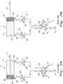
- Fig. 1there is shown a schematic representation of a typical actuator 1 known in the art, in which the actuator rod 2 is extended and retracted by a pressurized fluid acting against the faces 3A and 3B of the piston 3.
- Housing 4guides rod 2 and encloses piston 3 to form volumes 5A and 5B adjacent to piston faces 3A and 3B, respectively.
- Flow controls 7 and 8connect fluid lines 9A and 9B to double acting valve 10.
- Valve 10is able to connect lines 9A and 9B to either pressurized fluid supply 12 or exhaust 11, depending on the position of the valve 10.
- Flow controls 7 and 8can be in the form of throttling devices 7A and 8A and check valves 7B and 8B, respectively.
- Throttling devices 7A and 8Acan be adjusted to meter the flow rate of pressurized fluid passing through them.
- Check valves 7B and 8Bare configured to allow fluid to flow freely through them when the fluid is moving to enter the actuator 1 (i.e. when moving from line 9 toward port 6), while completely blocking flow when the fluid exits the actuator 1 (i.e. when moving from port 6 toward line 9). In this fashion, fluid flow entering the actuator 1 can pass freely through the open check valve, bypassing the restriction to flow created by the throttling device, while flow exiting the actuator 1 is forced by the closed check valve to the flow restriction created by the throttling device.
- this arrangementis known as "meter out" speed control, with the adjustable flow rate imposed on the fluid exhausting from the actuator 1 by the appropriate throttling device controlling the speed of the piston 3 and the actuator rod 2.
- Fig. 2Athere is shown a schematic operation of a typical actuator system known in the art, in which the actuator rod 2 is extending away from housing 4.
- Pressurized fluidflowing from supply 12, is routed by valve 10 to line 9B. Passing through open check valve 8B, the fluid bypasses throttling device 8A to enter port 6B and fill volume 5B.
- the fluid pressure acting against piston face 3Bacts to move the piston 3 and extend the attached actuator rod 2 away from housing 4.
- the pressurized fluid occupying volume 5Aexhausts through port 6A toward flow control 7. Closed check valve 7B forces the exhaust flow to pass through throttling device 7A, to govern the speed of the extending rod 2.
- Fig. 2Bthere is shown a schematic operation of the same actuator system shown in Fig. 2A , but when the actuator rod 2 is retracting toward housing 4.
- Pressurized fluidflowing from supply 12, is directed by valve 10 to line 9A. Passing through open check valve 7B, the fluid bypasses throttling device 7A to enter port 6A and fill volume 5A.
- the fluid pressure acting against piston face 3Aacts to move the piston 3 and retract the attached actuator rod 2 toward housing 4.
- the pressurized fluid occupying volume 5Bexhausts through port 6B toward flow control 8.
- Closed check valve 8Bforces the exhaust flow to pass through throttling device 8A, to govern the speed of the retracting rod 2.
- the exhaust flow from line 9Bpasses through valve 10 to be exhausted to ambient pressure through exhaust port 11.
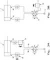
- Figs. 3A and 3Bschematically show some of the possible locations at which an energy harvester 20 can be integrated into an actuator system.
- the inventionis disclosed in conjunction with a pneumatic actuator producing a reciprocating linear motion, it is understood that the invention can also be applied to hydraulically powered actuators and actuators producing rotary or curvilinear motion.
- Fig. 3Ashows harvester 20 located adjacent to the ports 6A, 6B of actuator 1.
- the harvester 20can be configured to also incorporate the functions of flow control (check valve and throttling device) as shown in the harvester 20 located between port 6B and line 9B.
- the harvester 20can also be added adjacent to a discrete flow control as shown in the harvester 20 located between port 6A and line 9A. Locating the harvester adjacent to ports 6A, 6B offers the possible benefit of increasing the amount of energy available from the exhaust flow for harvest, since energy is lost from the exhaust flow in the form of frictional heat generated between the flow and walls of the conduit conveying the flow, as the flow moves progressively away from the ports 6A, 6B.
- a harvester 20 located adjacent to ports 6A, 6Bcan only harvest energy from the actuator port to which it is attached, creating the disadvantage of requiring two harvesters 20 to be used in order to extract energy from the entire quantity of fluid exhausted from the actuator 1.
- Fig. 3Bshows harvester 20 attached to the exhaust port 11 of valve 10. Locating the harvester 20 in this position, offers the advantage of allowing a single harvester 20 to extract energy from the entire quantity of fluid exhausted from the actuator 1, since both of the exhaust flows from both ports 6A, 6B of actuator 1 are alternately directed to common exhaust port 11 by valve 10. Locating the harvester 20 at exhaust port 11 has the possible disadvantage of reducing the amount of energy available from the exhaust flow for harvest, since energy is lost from the exhaust flow in the form of frictional heat generated between the flow and walls of the conduit conveying the flow, as the flow moves progressively away from actuator ports 6A, 6B.
- Fig. 4shows a schematic representation of the components of the energy harvesting system 20 according to the present invention.
- the energy harvesting system 20provides energy to external load 25.
- Energyis extracted from the exhaust fluid stream by converter 20A, which converts a portion of the potential energy stored in the compressed exhaust fluid into mechanical motion.
- Generator 20Bgenerates an electrical current from the mechanical motion produced by converter 20A.
- Charging controller 20Cdirects the electrical current produced by generator 20B into storage medium 20D during periods when the power produced by generator 20B exceeds the power demanded by external load 25.
- Charging controller 20Cprovides an electrical current from storage medium 20D to external load 25 during periods when the power demanded by the external load 25 exceeds the power produced by generator 20B.
- Converter 20Acan include any suitable means common in the art of converting fluid flow into mechanical motion. For example, impingement of the flow, either axially or tangentially, onto a bladed turbine can convert the fluid motion into rotation of the turbine.
- the action of a linear oscillating spring-mass positive volume displacement pumpcan be reversed so that the fluid flow produces a reciprocating linear motion.
- an alternating-valve-oscillating-piston-positive-volume-displacement pumpcan be used to produce a reciprocating linear motion.
- the action of a Wankle rotary pumpcan be reversed to produce rotary motion.
- the Bemoulii Effectcan be exploited to produce either a fluttering flexion or oscillating torsional twisting of a reed over which the fluid flow is directed.
- any means known in the artcan be used to perform the function of Generator 20B.
- the action of an electric motorcan be reversed to convert mechanical rotation into electrical current.
- Reciprocating linear motioncan be converted into electrical current by the action of a magnet moving relative to a helical coil formed by an electrical conductor encircling the magnet.
- Flexion of a reedcan be converted into an electrical current through a piezoelectric film laminated onto the reed.
- Laminated piezoelectric film or the reversed action of an electric motorare suitable to convert the torsional twisting of a reed into an electrical current.
- Charging controller 20Ccan include an electrical integrated circuit (IC) specifically designed for the task, such as the bq25504 IC which is manufactured for energy harvesting applications by Texas Instruments Corporation.
- ICelectrical integrated circuit
- Storage medium 20Dcan include any suitable combination of rechargeable batteries, super-capacitors, and/or conventional capacitors.
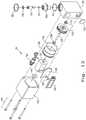
- Fig. 5shows an exploded isometric view
- Figs. 7 and 9show section views, of a first embodiment of energy harvester 20, intended to be located between port 6B and line 9B as shown in Fig. 3A .
- Bearing bushing 31is disposed into a mating bore in housing 30.
- Shaft 33is bonded to turbine 32 so that rotation of turbine 32 causes a like rotation of shaft 33, with one end of shaft 33 supported by bearing bushing 31.
- the opposing end of shaft 33is supported by bearing bushing 34.
- Bushing 34is disposed into a mating bore in plug 36. The actions of bearing bushings 31 and 34 allow shaft 33 and turbine 32 to rotate freely, while preventing axial translation of the shaft 33 and turbine 32 between plug 36 and housing 30.
- O-ring seal 35seals the periphery of plug 36 to prevent the ingress of moisture past the plug 36.
- the input shaft of electrical generator 37is bonded to one end of shaft 33 so that rotation of the shaft 33 by turbine 32 causes a like rotation of the generator input shaft.
- the electrical output terminals of generator 37are electrically connected to printed circuit board (PCB) 38.
- PCB 38electrically connected to PCB 38 are charging controller IC 39 and storage super-capacitor 40.
- Turbine 32, generator 37, charging controller IC 39, and storage super-capacitor 40perform the actions respectively of converter 20A, generator 20B, charging controller 20C, and storage medium 20D, which are shown schematically in Fig. 4 .
- Electrical connector 41connects electrically to PCB 38 and provides a way of connecting harvester 20 to an external load, represented schematically as load 25 in Fig. 4 .
- Elastomeric O-ring 42is disposed within a bore in cover 43 so as to remove any physical space that might occur between generator 37 and cover 43 resulting from the dimensional variation of the components that comprise the harvester 20.
- Threaded fasteners 44physically attach cover 43 to housing 30.
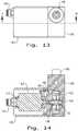
- An O-ring seal 45is disposed within a complimentary recess in a needle 47 ( Fig. 9 ).
- Check seal 46is disposed within a complimentary gland in needle 47.
- One end of pin 48is disposed within a mating bore in needle 47. The opposing end of pin 48 passes through a bore in cap 50.
- Pin 48is constrained from radial movement by the bore in cap 50, but the pin 48 is free to translate along the longitudinal axis of the cap 50.
- the flange portion of cap 50is disposed into a complimentary bore in housing 30.
- Retaining ring 52retains cap 50 within a mating bore in housing 30, while O-ring seal 49 prevents the passage of pressurized fluid around the flange portion of cap 50.
- Speed adjustment knob 53threads onto cap 50.
- Pin 54is secured into a mating bore in knob 53 after the knob 53 is threaded on the cap 50 to prevent the knob 53 from subsequently being able to be completely unthreaded from cap 50.
- O-ring seal 51seated within a complimentary gland in cap 50, seals against knob 53 to prevent the egress of fluid around pin 48.
- the housing 30has at least one fluid passageway, for example, it may include four fluid passageways in the form of a passage 62, a cavity 63, a nozzle 64, and a passage 65. Passages 62 and 65 fluidly connect ports 61 and 66, respectively, with the cavity 63.
- the moveable needle 47is associated with at least one fluid passageway of the housing 30. In the present embodiment, the needle 47 is disposed within the cavity 63 and can be selectively adjusted with respect to and engaged with the nozzle 64 to adjust and/or close off fluid flow therethrough. In this manner, the needle 47 is configured to adjust a flow of the fluid as it can adjust fluid flow within cavity 63 and through nozzle 64.
- Fig. 9shows the operation of harvester 20 when exhaust fluid is flowing from port 6B to line 9B (see also Fig. 3A ).
- Pressurized fluidenters port 61 in housing 30 and flows through passage 62 into cavity 63 and through the annular orifice formed between needle 47 and conical nozzle 64 in body 30.
- Nozzle 64directs the fluid flow to impinge upon the vanes of turbine 32 causing the turbine 32 to spin along with shaft 33.
- the exhaust flowdepleted of kinetic energy by the action of impingement against the vanes of turbine 32, subsequently exits housing 30 through outlet 67 and porous plug 55, which is retained in a complimentary bore in housing 30.
- Fluid pressure acting on the underside of check seal 46causes the skirt of the check seal 46 to inflate radially outwards to seal against the walls of cavity 63, preventing the flow of fluid through passage 65 and out of port 66 in housing 30.
- the axial position of needle 47 relative to nozzle 64determines the area of the annulus through which the fluid flows prior to exiting through the nozzle 64, creating the ability to meter the flow rate of the exhaust flow through the harvester 20.
- the axial position of knob 53 relative to cap 50provides a means of externally adjusting the axial position of needle 47 relative to nozzle 64 by restricting the axial movement of pin 48 as fluid pressure acting on the underside of check seal 46 exerts a force to push needle 47 away from nozzle 64.
- needle 47, pin 48, cap 50, knob 53, and check seal 46 with body 30form a throttling device and check valve which perform the function of the conventional speed controlling throttling device 8A and check valve 8B respectively, as shown schematically in Figs. 1 and 2 .
- Fig. 11shows the operation of harvester 20 when supply fluid is flowing from line 9B to actuator port 6B (see also Fig. 3A ).
- Pressurized fluid flowing from the supply 12enters port 66 in housing 30 and flows through passage 65 into cavity 63.
- the pressure of the fluid, acting on the topside of check seal 46causes the skirt of the check seal 46 to collapse, allowing the fluid to flow around the annular area formed between the periphery of the skirt and the walls of cavity 63.
- Fluid pressure acting on the topside of check seal 46 and the top surface of needle 47exerts a force to push needle 47 downwards until O-ring seal 45 seats against the bottom of cavity 63, which prevents the flow of fluid through nozzle 64 (see also Fig. 9 ).
- Fig. 12shows an exploded isometric view
- Figs. 14 and 16show section views, of a second embodiment of the energy harvester 20, suitable for attachment to exhaust port 11 of valve 10 as shown in Fig. 3B .
- Bearing bushing 131is disposed into a mating bore in housing 130.
- Shaft 133is bonded to turbine 132 so that rotation of turbine 132 causes a like rotation of shaft 133, with one end of shaft 133 supported by bearing bushing 131.
- the opposing end of shaft 133is supported by bearing bushing 134.
- Bushing 134is disposed into a mating bore in plug 136.
- bearing bushings 131 and 134allow shaft 133 and turbine 132 to rotate freely, while preventing axial translation of the shaft 133 and turbine 132 between plug 136 and housing 130.
- O-ring seal 135seals the periphery of plug 136 to prevent the ingress of moisture past the plug 136.
- the input shaft of electrical generator 137is bonded to one end of shaft 133 so that rotation of the shaft 133 by turbine 132 causes a like rotation of the generator input shaft.
- the electrical output terminals of generator 137are electrically connected to printed circuit board (PCB) 138. Also, electrically connected to PCB 138 are charging controller IC 139 and storage super-capacitor 140.
- Turbine 132, generator 137, charging controller IC 139, and storage super-capacitor 140perform the actions respectively of converter 20A, generator 20B, charging controller 20C, and storage medium 20D, as shown schematically in Fig. 4 .
- Electrical connector 141connects electrically to PCB 138 and provides a way of connecting harvester 20 to an external load, represented schematically as load 25 in Fig. 4 .
- Elastomeric O-ring 142is disposed within a bore in cover 143 so as to remove any physical space that might occur between generator 137 and cover 143 resulting from the dimensional variation of the components that comprise the harvester 20. Threaded fasteners 144 physically attach cover 143 to housing 130.
- Needle 147is disposed within a complimentary bore in cap 150 with a treaded portion of needle 147 engaging mating threads in cap 150. In this manner, rotation of needle 147 relative to cap 150 causes needle 147 to move along the longitudinal axis of cap 150. Retaining ring 148 prevents needle 147 from subsequently being able to be completely unthreaded from cap 150. O-ring seal 151 is disposed within a complimentary gland in needle 147 and prevents the egress of fluid between the bore in cap 151 and the body of needle 147. The flange portion of cap 150 is disposed into a complimentary bore in housing 130. Retaining ring 152 retains cap 150 within a mating bore in housing 130.
- the housing 130has at least one fluid passageway, for example, it may include three fluid passageways in the form of a passage 165, a cavity 163, and a nozzle 164. Passage 165 fluidly connects port 166 with the cavity 163.
- the moveable needle 147is associated with at least one fluid passageway of the housing 130. In the present embodiment, the needle 147 is partially disposed within the cavity 163 and can be selectively moved with respect to and engaged with the nozzle 164 to adjust and/or close off fluid flow therethrough. In this manner, the needle 147 is configured to adjust a flow of the fluid as it can adjust fluid flow within cavity 163 and through nozzle 164.
- pressurized fluidenters port 166 in housing 130 and flows through passage 165 into cavity 163 and through the annular orifice formed between needle 147 and conical nozzle 164 in body 130.
- Nozzle 164directs the fluid flow to impinge upon the vanes of turbine 132 causing the turbine 132 to spin along with shaft 133.
- the exhaust flowdepleted of kinetic energy by the action of impingement against the vanes of turbine 132, subsequently exits housing 130 through outlet 167 and porous plug 155, which is retained in a complimentary bore in housing 130.
- the axial position of needle 147 relative to nozzle 164determines the area of the annulus through which the fluid flows prior to exiting through the nozzle 164.
- needle 147is first rotated relative to cap 150, which remains stationary relative to body 130, to adjust the axial position of needle 147 so that needle 147 is fully retracted from nozzle 164.
- Throttling devices 7A and 8Amay be included and subsequently adjusted to obtain the desired extend and retract speeds of rod 2 of the actuator 1 (see also Figs. 1 and 2 ). Needle 147 is finally rotated relative to cap 150, to reduce the annular area formed between needle 147 and nozzle 164, until the reduction in area begins to reduce the extend and/or retract speed of actuator 1.
- exhaust fluidis caused to exit nozzle 164 at the highest flow speed practical without adversely altering the desired actuation speed of actuator 1.
- Such high flow speedprovides for an exhaust flow with a kinetic energy content as great as is possible, to provide for optimal energy transfer from the fluid to turbine rotor 132.
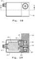
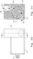
- Fig. 17shows an exploded isometric view
- Figs. 18 and 19show section views, of a third embodiment of the energy harvester 20, suitable for attachment to exhaust port 11 of valve 10 as shown in Fig. 3B .
- Bearing bushing 231is disposed into a mating bore in housing 230.
- Shaft 233is bonded to turbine 232 so that rotation of turbine 232 causes a like rotation of shaft 233, with one end of shaft 233 supported by bearing bushing 231.
- the opposing end of shaft 233is supported by bearing bushing 234.
- Bushing 234is disposed into a mating bore in plug 236.
- bearing bushings 231 and 234allow shaft 233 and turbine 232 to rotate freely, while preventing axial translation of the shaft 233 and turbine 232 between plug 236 and housing 230.
- O-ring seal 235seals the periphery of plug 236 to prevent the ingress of moisture past the plug 236.
- the input shaft of electrical generator 237is bonded to one end of shaft 233 so that rotation of the shaft 233 by turbine 232 causes a like rotation of the generator input shaft.
- the electrical output terminals of generator 237are electrically connected to printed circuit board (PCB) 238. Also, electrically connected to PCB 238 are charging controller IC 239 and storage super-capacitor 240.
- Turbine 232, generator 237, charging controller IC 239, and storage super-capacitor 240perform the actions respectively of converter 20A, generator 20B, charging controller 20C, and storage medium 20D, as shown schematically in Fig. 4 .
- Electrical connector 241connects electrically to PCB 238 and provides a way of connecting harvester 20 to an external load, represented schematically as load 25 in Fig. 4 .
- Elastomeric O-ring 242is disposed within a bore in cover 243 so as to remove any physical space that might occur between generator 237 and cover 243 resulting from the dimensional variation of the components that comprise the harvester 20. Threaded fasteners 244 physically attach cover 243 to housing 230.
- the housing 230has at least one fluid passageway, for example, it may include a fluid passageway in the form of a nozzle 264, e.g., a fixed orifice nozzle.
- the dimensions of nozzle 264are selectively chosen to control the velocity of fluid passing through the orifice so formed, creating the ability to meter the flow rate of the exhaust flow through the harvester 20.
- pressurized fluidenters port 266 in housing 230 and flows through the orifice formed by conical nozzle 264 in body 230.
- Nozzle 264directs the fluid flow to impinge upon the vanes of turbine 232 causing the turbine 232 to spin along with shaft 233.
- the exhaust flowdepleted of kinetic energy by the action of impingement against the vanes of turbine 232, subsequently exits housing 230 through outlet 267 and porous plug 255, which is retained in a complimentary bore in housing 230.
Landscapes
- Engineering & Computer Science (AREA)
- Mechanical Engineering (AREA)
- General Engineering & Computer Science (AREA)
- Chemical & Material Sciences (AREA)
- Combustion & Propulsion (AREA)
- Power Engineering (AREA)
- Connection Of Motors, Electrical Generators, Mechanical Devices, And The Like (AREA)
Description
- The present invention relates to energy harvesters, and, more particularly, to an exhaust fluid energy harvester in a motive system that generates electrical energy in order to store the electrical energy and/or use it to power an external load.
- Reference is made to
US 2008/155975 A1 , forming the preamble ofclaim 1. - Actuators are mechanical or electromechanical devices which convert energy into mechanical motion. Often, mechanical actuators are powered with a compressed fluid which alternately enters and exits a cylindrical volume to act against a movable piston and rod assembly. The rod is extended by fluid pressure acting on one face of the piston and is retracted when fluid acts on the opposing face of the piston. To affect motion, the face of the piston upon which motive fluid pressure acts must be continuously supplied with pressurized fluid from a supply, while any pressurized fluid acting on the opposing face of the piston is continuously exhausted so as to maintain a continuous pressure differential between the two faces. The motive force produced on the piston is proportional to the magnitude of this pressure differential.
- It is often advantageous to produce as large a motive force as possible by exhausting the fluid present on the exhaust side of the piston to as low a pressure as possible; typically, to the ambient pressure of the environment in which the actuator is operated. As the actuator cycles, moving the piston and rod attached to the piston in a reciprocating motion, the supply side of the piston on a given stroke of the piston and rod becomes the exhaust side of the piston on the successive stroke. The fluid on the supply side of piston is ideally maintained at the full pressure of the fluid supply in order to produce the maximum work output from the actuator. At the completion of a stroke, the volume of fluid on the supply side of the piston remains at full supply pressure until the fluid is subsequently exhausted during the reciprocal successive stroke. This volume of fully pressurized fluid contains a quantity of potential energy proportional to the volume and pressure of the fluid. As the fluid is exhausted to the low pressure environment or other low pressure sump, the potential energy stored in the compressed fluid is lost from the motive system. This loss of energy degrades the efficiency of the system.
- What is needed in the art is a cost-effective device to recoup as much of the lost energy as is practical, so as to increase the overall efficiency of the motive system.
- The present invention is directed to an actuating system as defined in
claim 1. Further advantageous features of the invention are defined in the dependent claims. - An advantage of the present invention is that greater efficiencies of a motive system can be achieved.
- Another advantage of the present invention is that harvested energy which would have been lost in a traditional motive system can be stored or used to perform work elsewhere in the motive system.
- Yet another advantage of the present invention is that motion of the actuator can be controlled while simultaneously harvesting energy from the exhaust fluid.
- The above-mentioned and other features and advantages of this invention, and the manner of attaining them, will become more apparent and the invention will be better understood by reference to the following descriptions of embodiments of the invention taken in conjunction with the accompanying drawings, wherein:
Fig. 1 is a schematic representation of a typical actuator known in the art;Figs. 2A-2B are schematic representations of the typical actuator as shown inFig. 1 , illustrating the movement of the piston and rod relative to the housing;Figs. 3A-3B are schematic representations of an actuator system incorporating an energy harvester according to the present invention;Fig. 4 is a schematic diagram illustrating an energy harvester according to the present invention;Fig. 5 is an exploded view of an embodiment of an energy harvester according to the present invention;Fig. 6 is a top view of the energy harvester as shown inFig. 5 ;Fig. 7 is a cross sectional view of the energy harvester as shown inFig. 6 taken across line 7-7;Fig. 8 is a side view of the energy harvester as shown inFig. 5 ;Fig. 9 is a cross sectional view of the energy harvester as shown inFig. 8 taken across line 9-9;Fig. 10 is a side view of the energy harvester as shown inFig. 5 ;Fig. 11 is a cross sectional view of the energy harvester as shown inFig. 10 taken across line 11-11;Fig. 12 is an exploded view of another embodiment of an energy harvester according to the present invention;Fig. 13 is a top view of the energy harvester as shown inFig. 12 ;Fig. 14 is a cross sectional view of the energy harvester as shown inFig. 13 taken across line 14-14;Fig. 15 is a side view of the energy harvester as shown inFig. 12 ;Fig. 16 is a cross sectional view of the energy harvester as shown inFig. 15 taken across line 16-16;Fig. 17 is an exploded view of another embodiment of an energy harvester according to the present invention;Fig. 18 is a top view of the energy harvester as shown inFig. 17 ;Fig. 19 is a cross sectional view of the energy harvester as shown inFig. 18 taken across line 19-19;Fig. 20 is a side view of the energy harvester as shown inFig. 17 ; andFig. 21 is a cross sectional view of the energy harvester as shown inFig. 20 taken across line 21-21.- Corresponding reference characters indicate corresponding parts throughout the several views. The exemplifications set out herein illustrate embodiments of the invention and such exemplifications are not to be construed as limiting the scope of the invention in any manner.
- Referring now to
Fig. 1 , there is shown a schematic representation of atypical actuator 1 known in the art, in which theactuator rod 2 is extended and retracted by a pressurized fluid acting against thefaces piston 3.Housing 4guides rod 2 and enclosespiston 3 to formvolumes piston faces Flow controls 7 and 8 connectfluid lines double acting valve 10. Valve 10 is able to connectlines fluid supply 12 orexhaust 11, depending on the position of thevalve 10.Flow controls 7 and 8 can be in the form ofthrottling devices check valves Throttling devices Check valves line 9 toward port 6), while completely blocking flow when the fluid exits the actuator 1 (i.e. when moving from port 6 toward line 9). In this fashion, fluid flow entering theactuator 1 can pass freely through the open check valve, bypassing the restriction to flow created by the throttling device, while flow exiting theactuator 1 is forced by the closed check valve to the flow restriction created by the throttling device. In the field of art, this arrangement is known as "meter out" speed control, with the adjustable flow rate imposed on the fluid exhausting from theactuator 1 by the appropriate throttling device controlling the speed of thepiston 3 and theactuator rod 2. - Referring now to
Fig. 2A , there is shown a schematic operation of a typical actuator system known in the art, in which theactuator rod 2 is extending away fromhousing 4. Pressurized fluid, flowing fromsupply 12, is routed byvalve 10 toline 9B. Passing throughopen check valve 8B, the fluid bypasses throttlingdevice 8A to enterport 6B and fillvolume 5B. The fluid pressure acting againstpiston face 3B acts to move thepiston 3 and extend the attachedactuator rod 2 away fromhousing 4. Simultaneously, the pressurizedfluid occupying volume 5A exhausts throughport 6A towardflow control 7.Closed check valve 7B forces the exhaust flow to pass through throttlingdevice 7A, to govern the speed of the extendingrod 2. - The exhaust flow from
line 9A passes throughvalve 10 to be exhausted to ambient pressure throughexhaust port 11. - Referring now to
Fig. 2B , there is shown a schematic operation of the same actuator system shown inFig. 2A , but when theactuator rod 2 is retracting towardhousing 4. Pressurized fluid, flowing fromsupply 12, is directed byvalve 10 toline 9A. Passing throughopen check valve 7B, the fluid bypasses throttlingdevice 7A to enterport 6A and fillvolume 5A. The fluid pressure acting againstpiston face 3A acts to move thepiston 3 and retract the attachedactuator rod 2 towardhousing 4. Simultaneously, the pressurizedfluid occupying volume 5B exhausts throughport 6B toward flow control 8.Closed check valve 8B forces the exhaust flow to pass through throttlingdevice 8A, to govern the speed of the retractingrod 2. The exhaust flow fromline 9B passes throughvalve 10 to be exhausted to ambient pressure throughexhaust port 11. Figs. 3A and 3B schematically show some of the possible locations at which anenergy harvester 20 can be integrated into an actuator system. Although the invention is disclosed in conjunction with a pneumatic actuator producing a reciprocating linear motion, it is understood that the invention can also be applied to hydraulically powered actuators and actuators producing rotary or curvilinear motion.Fig. 3A showsharvester 20 located adjacent to theports actuator 1. Theharvester 20 can be configured to also incorporate the functions of flow control (check valve and throttling device) as shown in theharvester 20 located betweenport 6B andline 9B. Theharvester 20 can also be added adjacent to a discrete flow control as shown in theharvester 20 located betweenport 6A andline 9A. Locating the harvester adjacent toports ports harvester 20 located adjacent toports harvesters 20 to be used in order to extract energy from the entire quantity of fluid exhausted from theactuator 1.Fig. 3B showsharvester 20 attached to theexhaust port 11 ofvalve 10. Locating theharvester 20 in this position, offers the advantage of allowing asingle harvester 20 to extract energy from the entire quantity of fluid exhausted from theactuator 1, since both of the exhaust flows from bothports actuator 1 are alternately directed tocommon exhaust port 11 byvalve 10. Locating theharvester 20 atexhaust port 11 has the possible disadvantage of reducing the amount of energy available from the exhaust flow for harvest, since energy is lost from the exhaust flow in the form of frictional heat generated between the flow and walls of the conduit conveying the flow, as the flow moves progressively away fromactuator ports Fig. 4 shows a schematic representation of the components of theenergy harvesting system 20 according to the present invention. Theenergy harvesting system 20 provides energy toexternal load 25. Energy is extracted from the exhaust fluid stream byconverter 20A, which converts a portion of the potential energy stored in the compressed exhaust fluid into mechanical motion.Generator 20B generates an electrical current from the mechanical motion produced byconverter 20A.Charging controller 20C directs the electrical current produced bygenerator 20B intostorage medium 20D during periods when the power produced bygenerator 20B exceeds the power demanded byexternal load 25.Charging controller 20C provides an electrical current fromstorage medium 20D toexternal load 25 during periods when the power demanded by theexternal load 25 exceeds the power produced bygenerator 20B.Converter 20A can include any suitable means common in the art of converting fluid flow into mechanical motion. For example, impingement of the flow, either axially or tangentially, onto a bladed turbine can convert the fluid motion into rotation of the turbine. The action of a linear oscillating spring-mass positive volume displacement pump can be reversed so that the fluid flow produces a reciprocating linear motion. In a similar manner, an alternating-valve-oscillating-piston-positive-volume-displacement pump can be used to produce a reciprocating linear motion. The action of a Wankle rotary pump can be reversed to produce rotary motion. The Bemoulii Effect can be exploited to produce either a fluttering flexion or oscillating torsional twisting of a reed over which the fluid flow is directed.- Any means known in the art can be used to perform the function of
Generator 20B. For example, the action of an electric motor can be reversed to convert mechanical rotation into electrical current. Reciprocating linear motion can be converted into electrical current by the action of a magnet moving relative to a helical coil formed by an electrical conductor encircling the magnet. Flexion of a reed can be converted into an electrical current through a piezoelectric film laminated onto the reed. Laminated piezoelectric film or the reversed action of an electric motor are suitable to convert the torsional twisting of a reed into an electrical current. Charging controller 20C can include an electrical integrated circuit (IC) specifically designed for the task, such as the bq25504 IC which is manufactured for energy harvesting applications by Texas Instruments Corporation.Storage medium 20D can include any suitable combination of rechargeable batteries, super-capacitors, and/or conventional capacitors.Fig. 5 shows an exploded isometric view, andFigs. 7 and9 show section views, of a first embodiment ofenergy harvester 20, intended to be located betweenport 6B andline 9B as shown inFig. 3A . Bearingbushing 31 is disposed into a mating bore inhousing 30.Shaft 33 is bonded toturbine 32 so that rotation ofturbine 32 causes a like rotation ofshaft 33, with one end ofshaft 33 supported by bearingbushing 31. The opposing end ofshaft 33 is supported by bearingbushing 34.Bushing 34 is disposed into a mating bore inplug 36. The actions of bearingbushings shaft 33 andturbine 32 to rotate freely, while preventing axial translation of theshaft 33 andturbine 32 betweenplug 36 andhousing 30. O-ring seal 35 seals the periphery ofplug 36 to prevent the ingress of moisture past theplug 36. The input shaft ofelectrical generator 37 is bonded to one end ofshaft 33 so that rotation of theshaft 33 byturbine 32 causes a like rotation of the generator input shaft. The electrical output terminals ofgenerator 37 are electrically connected to printed circuit board (PCB) 38. Also, electrically connected toPCB 38 are chargingcontroller IC 39 andstorage super-capacitor 40.Turbine 32,generator 37, chargingcontroller IC 39, andstorage super-capacitor 40 perform the actions respectively ofconverter 20A,generator 20B, chargingcontroller 20C, andstorage medium 20D, which are shown schematically inFig. 4 .Electrical connector 41 connects electrically toPCB 38 and provides a way of connectingharvester 20 to an external load, represented schematically asload 25 inFig. 4 . Elastomeric O-ring 42 is disposed within a bore incover 43 so as to remove any physical space that might occur betweengenerator 37 and cover 43 resulting from the dimensional variation of the components that comprise theharvester 20. Threadedfasteners 44 physically attachcover 43 tohousing 30. An O-ring seal 45 is disposed within a complimentary recess in a needle 47 (Fig. 9 ). Checkseal 46 is disposed within a complimentary gland inneedle 47. One end ofpin 48 is disposed within a mating bore inneedle 47. The opposing end ofpin 48 passes through a bore incap 50.Pin 48 is constrained from radial movement by the bore incap 50, but thepin 48 is free to translate along the longitudinal axis of thecap 50. The flange portion ofcap 50 is disposed into a complimentary bore inhousing 30. Retainingring 52 retainscap 50 within a mating bore inhousing 30, while O-ring seal 49 prevents the passage of pressurized fluid around the flange portion ofcap 50.Speed adjustment knob 53 threads ontocap 50.Pin 54 is secured into a mating bore inknob 53 after theknob 53 is threaded on thecap 50 to prevent theknob 53 from subsequently being able to be completely unthreaded fromcap 50. O-ring seal 51, seated within a complimentary gland incap 50, seals againstknob 53 to prevent the egress of fluid aroundpin 48.Arrows 60 inFigs. 9 and11 show the direction of flow of pressurized fluid throughharvester 20. Thehousing 30 has at least one fluid passageway, for example, it may include four fluid passageways in the form of apassage 62, acavity 63, anozzle 64, and apassage 65.Passages ports cavity 63. Themoveable needle 47 is associated with at least one fluid passageway of thehousing 30. In the present embodiment, theneedle 47 is disposed within thecavity 63 and can be selectively adjusted with respect to and engaged with thenozzle 64 to adjust and/or close off fluid flow therethrough. In this manner, theneedle 47 is configured to adjust a flow of the fluid as it can adjust fluid flow withincavity 63 and throughnozzle 64.Fig. 9 shows the operation ofharvester 20 when exhaust fluid is flowing fromport 6B toline 9B (see alsoFig. 3A ). Pressurized fluid entersport 61 inhousing 30 and flows throughpassage 62 intocavity 63 and through the annular orifice formed betweenneedle 47 andconical nozzle 64 inbody 30.Nozzle 64 directs the fluid flow to impinge upon the vanes ofturbine 32 causing theturbine 32 to spin along withshaft 33. The exhaust flow, depleted of kinetic energy by the action of impingement against the vanes ofturbine 32, subsequently exitshousing 30 throughoutlet 67 andporous plug 55, which is retained in a complimentary bore inhousing 30. Fluid pressure acting on the underside ofcheck seal 46 causes the skirt of thecheck seal 46 to inflate radially outwards to seal against the walls ofcavity 63, preventing the flow of fluid throughpassage 65 and out ofport 66 inhousing 30. The axial position ofneedle 47 relative tonozzle 64 determines the area of the annulus through which the fluid flows prior to exiting through thenozzle 64, creating the ability to meter the flow rate of the exhaust flow through theharvester 20. The axial position ofknob 53 relative to cap 50 provides a means of externally adjusting the axial position ofneedle 47 relative tonozzle 64 by restricting the axial movement ofpin 48 as fluid pressure acting on the underside ofcheck seal 46 exerts a force to pushneedle 47 away fromnozzle 64. In this manner,needle 47,pin 48,cap 50,knob 53, and checkseal 46 withbody 30 form a throttling device and check valve which perform the function of the conventional speed controllingthrottling device 8A andcheck valve 8B respectively, as shown schematically inFigs. 1 and2 .Fig. 11 shows the operation ofharvester 20 when supply fluid is flowing fromline 9B to actuatorport 6B (see alsoFig. 3A ). Pressurized fluid flowing from thesupply 12 entersport 66 inhousing 30 and flows throughpassage 65 intocavity 63. The pressure of the fluid, acting on the topside ofcheck seal 46, causes the skirt of thecheck seal 46 to collapse, allowing the fluid to flow around the annular area formed between the periphery of the skirt and the walls ofcavity 63. Fluid pressure acting on the topside ofcheck seal 46 and the top surface ofneedle 47 exerts a force to pushneedle 47 downwards until O-ring seal 45 seats against the bottom ofcavity 63, which prevents the flow of fluid through nozzle 64 (see alsoFig. 9 ). The flow exitscavity 63 throughpassage 62 and passes out ofport 61 inhousing 30 to supplyport 6B ofactuator 1 with pressurized fluid.Fig. 12 shows an exploded isometric view, andFigs. 14 and16 show section views, of a second embodiment of theenergy harvester 20, suitable for attachment to exhaustport 11 ofvalve 10 as shown inFig. 3B .Bearing bushing 131 is disposed into a mating bore inhousing 130.Shaft 133 is bonded toturbine 132 so that rotation ofturbine 132 causes a like rotation ofshaft 133, with one end ofshaft 133 supported by bearingbushing 131. The opposing end ofshaft 133 is supported by bearingbushing 134.Bushing 134 is disposed into a mating bore inplug 136. The actions of bearingbushings shaft 133 andturbine 132 to rotate freely, while preventing axial translation of theshaft 133 andturbine 132 betweenplug 136 andhousing 130. O-ring seal 135 seals the periphery ofplug 136 to prevent the ingress of moisture past theplug 136. The input shaft ofelectrical generator 137 is bonded to one end ofshaft 133 so that rotation of theshaft 133 byturbine 132 causes a like rotation of the generator input shaft. The electrical output terminals ofgenerator 137 are electrically connected to printed circuit board (PCB) 138. Also, electrically connected toPCB 138 are chargingcontroller IC 139 andstorage super-capacitor 140.Turbine 132,generator 137, chargingcontroller IC 139, andstorage super-capacitor 140 perform the actions respectively ofconverter 20A,generator 20B, chargingcontroller 20C, andstorage medium 20D, as shown schematically inFig. 4 .Electrical connector 141 connects electrically toPCB 138 and provides a way of connectingharvester 20 to an external load, represented schematically asload 25 inFig. 4 . Elastomeric O-ring 142 is disposed within a bore incover 143 so as to remove any physical space that might occur betweengenerator 137 and cover 143 resulting from the dimensional variation of the components that comprise theharvester 20. Threadedfasteners 144 physically attachcover 143 tohousing 130.Needle 147 is disposed within a complimentary bore incap 150 with a treaded portion ofneedle 147 engaging mating threads incap 150. In this manner, rotation ofneedle 147 relative to cap 150 causes needle 147 to move along the longitudinal axis ofcap 150. Retainingring 148 preventsneedle 147 from subsequently being able to be completely unthreaded fromcap 150. O-ring seal 151 is disposed within a complimentary gland inneedle 147 and prevents the egress of fluid between the bore incap 151 and the body ofneedle 147. The flange portion ofcap 150 is disposed into a complimentary bore inhousing 130. Retainingring 152 retainscap 150 within a mating bore inhousing 130.Arrows 160 inFig. 16 show the direction of flow of pressurized exhaust fluid throughharvester 20. Thehousing 130 has at least one fluid passageway, for example, it may include three fluid passageways in the form of apassage 165, acavity 163, and anozzle 164.Passage 165 fluidly connectsport 166 with thecavity 163. Themoveable needle 147 is associated with at least one fluid passageway of thehousing 130. In the present embodiment, theneedle 147 is partially disposed within thecavity 163 and can be selectively moved with respect to and engaged with thenozzle 164 to adjust and/or close off fluid flow therethrough. In this manner, theneedle 147 is configured to adjust a flow of the fluid as it can adjust fluid flow withincavity 163 and throughnozzle 164.- In operation, pressurized fluid enters
port 166 inhousing 130 and flows throughpassage 165 intocavity 163 and through the annular orifice formed betweenneedle 147 andconical nozzle 164 inbody 130.Nozzle 164 directs the fluid flow to impinge upon the vanes ofturbine 132 causing theturbine 132 to spin along withshaft 133. The exhaust flow, depleted of kinetic energy by the action of impingement against the vanes ofturbine 132, subsequently exitshousing 130 throughoutlet 167 andporous plug 155, which is retained in a complimentary bore inhousing 130. - The axial position of
needle 147 relative tonozzle 164 determines the area of the annulus through which the fluid flows prior to exiting through thenozzle 164. During operation of theharvester 20,needle 147 is first rotated relative to cap 150, which remains stationary relative tobody 130, to adjust the axial position ofneedle 147 so thatneedle 147 is fully retracted fromnozzle 164.Throttling devices rod 2 of the actuator 1 (see alsoFigs. 1 and2 ).Needle 147 is finally rotated relative to cap 150, to reduce the annular area formed betweenneedle 147 andnozzle 164, until the reduction in area begins to reduce the extend and/or retract speed ofactuator 1. In this manner, exhaust fluid is caused to exitnozzle 164 at the highest flow speed practical without adversely altering the desired actuation speed ofactuator 1. Such high flow speed provides for an exhaust flow with a kinetic energy content as great as is possible, to provide for optimal energy transfer from the fluid toturbine rotor 132. Fig. 17 shows an exploded isometric view, andFigs. 18 and 19 show section views, of a third embodiment of theenergy harvester 20, suitable for attachment to exhaustport 11 ofvalve 10 as shown inFig. 3B . Such an embodiment may be desirable as a lower cost alternative for those applications wherein optimization of the harvested energy is not required.Bearing bushing 231 is disposed into a mating bore inhousing 230.Shaft 233 is bonded toturbine 232 so that rotation ofturbine 232 causes a like rotation ofshaft 233, with one end ofshaft 233 supported by bearingbushing 231. The opposing end ofshaft 233 is supported by bearingbushing 234.Bushing 234 is disposed into a mating bore inplug 236. The actions of bearingbushings shaft 233 andturbine 232 to rotate freely, while preventing axial translation of theshaft 233 andturbine 232 betweenplug 236 andhousing 230. O-ring seal 235 seals the periphery ofplug 236 to prevent the ingress of moisture past theplug 236. The input shaft ofelectrical generator 237 is bonded to one end ofshaft 233 so that rotation of theshaft 233 byturbine 232 causes a like rotation of the generator input shaft. The electrical output terminals ofgenerator 237 are electrically connected to printed circuit board (PCB) 238. Also, electrically connected toPCB 238 are chargingcontroller IC 239 andstorage super-capacitor 240.Turbine 232,generator 237, chargingcontroller IC 239, andstorage super-capacitor 240 perform the actions respectively ofconverter 20A,generator 20B, chargingcontroller 20C, andstorage medium 20D, as shown schematically inFig. 4 .Electrical connector 241 connects electrically toPCB 238 and provides a way of connectingharvester 20 to an external load, represented schematically asload 25 inFig. 4 . Elastomeric O-ring 242 is disposed within a bore incover 243 so as to remove any physical space that might occur betweengenerator 237 and cover 243 resulting from the dimensional variation of the components that comprise theharvester 20. Threadedfasteners 244 physically attachcover 243 tohousing 230.Arrows 260 inFig. 21 show the direction of flow of pressurized exhaust fluid throughharvester 20. Thehousing 230 has at least one fluid passageway, for example, it may include a fluid passageway in the form of anozzle 264, e.g., a fixed orifice nozzle. The dimensions ofnozzle 264 are selectively chosen to control the velocity of fluid passing through the orifice so formed, creating the ability to meter the flow rate of the exhaust flow through theharvester 20.- In operation, pressurized fluid enters
port 266 inhousing 230 and flows through the orifice formed byconical nozzle 264 inbody 230.Nozzle 264 directs the fluid flow to impinge upon the vanes ofturbine 232 causing theturbine 232 to spin along withshaft 233. The exhaust flow, depleted of kinetic energy by the action of impingement against the vanes ofturbine 232, subsequently exitshousing 230 throughoutlet 267 andporous plug 255, which is retained in a complimentary bore inhousing 230.
Claims (12)
- An actuating system, comprising:a fluid supply (12) for supplying a fluid;an actuator (1), including:a piston (3) having a piston rod, a first piston face (3A), and a second piston face (3B);a piston housing (4) substantially encasing the piston (3) and defining a first volume (5A) and a second volume (5B) respectively adjacent to the first piston face (3A) and the second piston face (3B); anda first port and a second port fluidly connected respectively with the first volume (5A) and the second volume (5B) of the piston housing (4);a valve fluidly connected to the fluid supply and the actuator (1), and having an exhaust port; anda fluid energy harvester (20) fluidly connected to the actuator (1),characterized in that the fluid energy harvester (20) comprises:a housing (30) having at least one port and an outlet (67), and said housing (30) defining at least one fluid passageway therein;a turbine (32) disposed within the housing (30) and configured to convert at least a portion of potential energy in an exhaust fluid;an electric generator (37) operably coupled to the turbine (32);a charging controller (39) electrically coupled to the generator (37);a storage medium (40) electrically coupled to the generator (37) and configured to store the electrical current generated by the generator (37); anda nozzle (64) configured to control a flow of the exhaust fluid;the turbine (32) is located in the housing (30) such that the turbine (32) receives exhaust fluid from one of the ports;- the generator (37) is arranged coaxially with regard to the turbine (32);- a cover (43) which is connected to the housing (30) receives the generator (37) the charging controller (39) and the storage medium (40);the at least one fluid passageway of the housing includes a nozzle (64);a moveable needle can move relative to the nozzle (64) and can engage with said nozzle to block the flow of the fluid from passing through the nozzle, and the moveable needle can disengage from said nozzle (64) to allow the flow of the fluid to pass through the nozzle (64) and thereby to the turbine (32);the moveable needle controls at least one of the fluid entering and exiting said actuator such that a speed of the piston is regulated.
- The actuating system of claim 1, wherein the nozzle (64) directs the flow of the exhaust fluid to impinge upon the turbine (32) such that the exhaust fluid is depleted of potential energy.
- The actuating system of claim 1 or 2, including a circuit board that is electrically coupled to the generator and the charging controller.
- The actuating system of at least one of claims 1 to 3, providing at least a portion of the electrical current in the form of a power supply to an external load that is electrically coupled to the fluid energy harvester.
- The actuating system at least one of claims 1 to 4, wherein the charging controller (39) directs the electrical current generated by the generator (37) into the storage medium (40) during a period when the electrical current produced by the generator (37) exceeds a demand by the external load, and the charging controller (39) provides the electrical current stored in the storage medium (40) to said external load during a period when the demand by the external load exceeds the electrical current produced by generator (37).
- The actuating system of claim 5, wherein fluid flowing to the actuator (1) passes through said first port of the housing (30) of the fluid energy harvester (20), causing the moveable needle to engage with the nozzle (67), and thereby allowing the fluid to freely pass through said second port of the housing (30) of the fluid energy harvester (20) to said actuator (1), and the fluid exhausting from said actuator (1) passes through the second port of the housing (30) of the fluid energy harvester (20), causing the moveable needle to disengage from the nozzle (67), and thereby allowing the fluid to flow to the turbine (32) and exit through said outlet of the housing (30) of the fluid energy harvester (20).
- The actuating system of at least one of claims 1 to 6, wherein the fluid energy harvester (20) further includes a pin, a cap, a knob, and a check seal associated with said housing of the fluid energy harvester whereby the cap partially houses the pin, the knob threads onto the cap, the pin is coupled to the needle and is free to translate longitudinally within the cap, and the check seal is affixed to the needle such that the needle, pin, cap, knob, and check seal together perform a respective function of at least one of a throttling device and a check valve.
- The actuating system of claim 7, wherein knob can be adjusted by a user to adjust a position of said needle within said at least one passageway of said housing of the fluid energy harvester in order to adjust a speed of said piston.
- The actuating system of at least one of claims 1 to 8, wherein the fluid energy harvester is located adjacent to at least one of the first and second port.
- The actuating system of claim 1, wherein the moveable needle can be adjusted to restrict at least a portion of the fluid passing through the nozzle to the converter such that a speed of the piston is regulated.
- The actuating system of at least one of claims 7 to 10, wherein the fluid energy harvester is located downstream and adjacent to said exhaust port of said valve.
- The actuating system of at least one of claims 7 to 11, wherein the fluid energy harvester is located downstream and adjacent to a discrete flow control.
Applications Claiming Priority (1)
| Application Number | Priority Date | Filing Date | Title |
|---|---|---|---|
| US201662314527P | 2016-03-29 | 2016-03-29 |
Publications (2)
| Publication Number | Publication Date |
|---|---|
| EP3228861A1 EP3228861A1 (en) | 2017-10-11 |
| EP3228861B1true EP3228861B1 (en) | 2020-02-19 |
Family
ID=58709698
Family Applications (1)
| Application Number | Title | Priority Date | Filing Date |
|---|---|---|---|
| EP17163253.2AActiveEP3228861B1 (en) | 2016-03-29 | 2017-03-28 | Actuator exhaust fluid energy harvester |
Country Status (3)
| Country | Link |
|---|---|
| US (1) | US10075045B2 (en) |
| EP (1) | EP3228861B1 (en) |
| ES (1) | ES2775748T3 (en) |
Families Citing this family (2)
| Publication number | Priority date | Publication date | Assignee | Title |
|---|---|---|---|---|
| IT201900002827A1 (en)* | 2019-02-27 | 2020-08-27 | Elt Fluid S R L | HYDRAULIC SYSTEM WITH TURBINE |
| BR102021012927A2 (en)* | 2021-06-29 | 2023-01-03 | José James Mendes Pessoa | SYSTEM AND METHOD FOR ELECTRIC POWER GENERATION, HYBRID HEAVY VEHICLE, RAIL TRAIN AND VESSEL |
Family Cites Families (36)
| Publication number | Priority date | Publication date | Assignee | Title |
|---|---|---|---|---|
| US4086764A (en) | 1976-04-13 | 1978-05-02 | Brown Steven H | Hydroturbine engine device |
| US4095118A (en) | 1976-11-26 | 1978-06-13 | Rathbun Kenneth R | Solar-mhd energy conversion system |
| US5559379A (en)* | 1993-02-03 | 1996-09-24 | Nartron Corporation | Induction air driven alternator and method for converting intake air into current |
| US5775107A (en) | 1996-10-21 | 1998-07-07 | Sparkman; Scott | Solar powered electrical generating system |
| US6885114B2 (en)* | 1999-10-05 | 2005-04-26 | Access Business Group International, Llc | Miniature hydro-power generation system |
| US6956300B2 (en) | 2003-08-04 | 2005-10-18 | Andrew Roman Gizara | Gimbal-mounted hydroelectric turbine |
| US7088012B2 (en) | 2004-12-21 | 2006-08-08 | Andrew Roman Gizara | Transverse hydroelectric generator |
| DE102006029403A1 (en) | 2006-06-27 | 2008-01-03 | Daimlerchrysler Ag | Hydraulically propelled engine aggregate e.g. centrifugal oil separator, for internal combustion engine, has rotary component coupled with wheel, which is subjected with fluid from fluid line that is closed by valve in range of idle speed |
| US20080155975A1 (en)* | 2006-12-28 | 2008-07-03 | Caterpillar Inc. | Hydraulic system with energy recovery |
| SE531940C2 (en)* | 2007-01-10 | 2009-09-15 | Xerex Ab | Ejector |
| US20080217923A1 (en)* | 2007-03-06 | 2008-09-11 | Jen-Yen Yen | Hydraulic powered electric generator device |
| US20080217921A1 (en) | 2007-03-09 | 2008-09-11 | Michael William Raftery | Wave energy harnessing device |
| DE102007052959B4 (en) | 2007-03-15 | 2018-11-08 | Korea Institute Of Energy Research | Portable power generating device, fuel and air supply device for the portable power generating device, DC powered micro-motor for the portable power generating device |
| US20080231056A1 (en)* | 2007-03-20 | 2008-09-25 | Chang Ting Wen | Hydroelectric generator turbine flow guide structure |
| EA015612B1 (en) | 2007-04-17 | 2011-10-31 | Аэрокинетик Энерджи Корпорэйшн | Fluid powered generator |
| CZ302396B6 (en)* | 2007-08-03 | 2011-04-27 | Ceské vysoké ucení technické, Fakulta stavební | Fluid turbine |
| US8092675B2 (en)* | 2007-10-08 | 2012-01-10 | Zodiac Group Australia Pty. Ltd. | Energy generation methods and systems for swimming pools and other vessels with recirculating fluid |
| US7750491B2 (en) | 2007-11-21 | 2010-07-06 | Ric Enterprises | Fluid-dynamic renewable energy harvesting system |
| US8040022B2 (en) | 2007-12-12 | 2011-10-18 | Aprolase Development Co., Llc | Forced vibration piezo generator and piezo actuator |
| US7832207B2 (en)* | 2008-04-09 | 2010-11-16 | Sustainx, Inc. | Systems and methods for energy storage and recovery using compressed gas |
| US7977924B2 (en) | 2008-11-03 | 2011-07-12 | Rosemount Inc. | Industrial process power scavenging device and method of deriving process device power from an industrial process |
| US8467907B2 (en) | 2009-01-17 | 2013-06-18 | Certus Process Solutions | Automated valve with self-contained valve actuator system |
| US8415819B2 (en) | 2009-08-06 | 2013-04-09 | ISC8 Inc. | Energy harvesting buoy |
| US8698333B2 (en)* | 2009-09-23 | 2014-04-15 | Zurn Industries, Llc | Flush valve hydrogenerator |
| JP4656612B1 (en)* | 2009-09-29 | 2011-03-23 | Toto株式会社 | Faucet hydroelectric generator |
| EP2582976B1 (en)* | 2010-06-16 | 2019-08-21 | ClearMotion, Inc. | Integrated energy generating damper |
| JP5681459B2 (en)* | 2010-11-25 | 2015-03-11 | 川崎重工業株式会社 | Water current generator |
| US8424287B2 (en) | 2011-03-30 | 2013-04-23 | GM Global Technology Operations LLC | Electric preheating of a catalytic convertor using a solar cell array |
| US9090253B2 (en) | 2012-01-30 | 2015-07-28 | Enow, Inc. | Method and apparatus for vehicular energy management |
| US8581446B2 (en) | 2012-02-06 | 2013-11-12 | Elwha Llc | Method and apparatus for removal of harmonic noise |
| US20150108758A1 (en) | 2013-10-23 | 2015-04-23 | Thomas W. Oakes | Turbine system and method constructed for efficient low fluid flow rate operation |
| EP3141710B1 (en)* | 2013-12-16 | 2024-02-14 | BITZER Kühlmaschinenbau GmbH | Device and method for operating volumetric expansion machines |
| WO2015148853A2 (en)* | 2014-03-26 | 2015-10-01 | Energy Recovery, Inc. | Hydraulic turbine system with auxiliary nozzles |
| US9534585B2 (en)* | 2014-06-02 | 2017-01-03 | Aaron C. Smith | System using natural resources to generate electricity from a pressurized fluid |
| US10233911B2 (en) | 2015-02-10 | 2019-03-19 | Energy Intelligence, Inc. | Energy harvesting system |
| US9926807B2 (en)* | 2015-03-04 | 2018-03-27 | Honeywell International Inc. | Generator temperature management for throttle loss recovery systems |
- 2017
- 2017-03-28EPEP17163253.2Apatent/EP3228861B1/enactiveActive
- 2017-03-28USUS15/470,959patent/US10075045B2/enactiveActive
- 2017-03-28ESES17163253Tpatent/ES2775748T3/enactiveActive
Non-Patent Citations (1)
| Title |
|---|
| None* |
Also Published As
| Publication number | Publication date |
|---|---|
| US20170288502A1 (en) | 2017-10-05 |
| US10075045B2 (en) | 2018-09-11 |
| EP3228861A1 (en) | 2017-10-11 |
| ES2775748T3 (en) | 2020-07-28 |
Similar Documents
| Publication | Publication Date | Title |
|---|---|---|
| JP7343659B2 (en) | Integrated energy generation damper | |
| US7513112B2 (en) | Reservoir built-in type actuator | |
| EP2122186A1 (en) | Fluid control system having selective recruitable actuators | |
| EP3228861B1 (en) | Actuator exhaust fluid energy harvester | |
| JP5596121B2 (en) | High pressure variable displacement piston pump | |
| US4343153A (en) | Anti-supercharge pressure valve | |
| US20200271136A1 (en) | Flow control for an actuator | |
| CN107109961B (en) | Actuating drive for a control valve, in particular a steam turbine control valve, and method for operating the actuating drive | |
| US9261116B2 (en) | Hydraulic valve with helical actuator | |
| EP2440792B1 (en) | Proportional position feedback hydraulic servo system | |
| US8734123B2 (en) | Converter for converting mechanical energy into hydraulic energy and robot implementing said converter | |
| JP2002213405A (en) | Motor driven actuator having hydraulic power amplification | |
| WO2000016464A2 (en) | Control system with integrated actuation package | |
| US11821443B2 (en) | Actuator overpressurising assembly | |
| CN212775856U (en) | Small-sized integrated speed-changing main valve actuator | |
| CN107002716A (en) | Actuating drive for a control valve, in particular a steam turbine control valve, and method for operating the same | |
| TWI354741B (en) | Automatic adapted damping shock absorber | |
| CN102597499B (en) | Controls for hydraulic motors | |
| Tu et al. | The advantages and feasibility of externally actuating a high-speed rotary on/off valve | |
| RU2295658C1 (en) | Air-operated drive | |
| WO2005106243A1 (en) | Wind turbine teeter control | |
| JPH0443876A (en) | Output controller in hydraulic device of construction machine |
Legal Events
| Date | Code | Title | Description |
|---|---|---|---|
| PUAI | Public reference made under article 153(3) epc to a published international application that has entered the european phase | Free format text:ORIGINAL CODE: 0009012 | |
| STAA | Information on the status of an ep patent application or granted ep patent | Free format text:STATUS: THE APPLICATION HAS BEEN PUBLISHED | |
| AK | Designated contracting states | Kind code of ref document:A1 Designated state(s):AL AT BE BG CH CY CZ DE DK EE ES FI FR GB GR HR HU IE IS IT LI LT LU LV MC MK MT NL NO PL PT RO RS SE SI SK SM TR | |
| AX | Request for extension of the european patent | Extension state:BA ME | |
| STAA | Information on the status of an ep patent application or granted ep patent | Free format text:STATUS: REQUEST FOR EXAMINATION WAS MADE | |
| 17P | Request for examination filed | Effective date:20171229 | |
| RBV | Designated contracting states (corrected) | Designated state(s):AL AT BE BG CH CY CZ DE DK EE ES FI FR GB GR HR HU IE IS IT LI LT LU LV MC MK MT NL NO PL PT RO RS SE SI SK SM TR | |
| STAA | Information on the status of an ep patent application or granted ep patent | Free format text:STATUS: EXAMINATION IS IN PROGRESS | |
| 17Q | First examination report despatched | Effective date:20180625 | |
| GRAP | Despatch of communication of intention to grant a patent | Free format text:ORIGINAL CODE: EPIDOSNIGR1 | |
| STAA | Information on the status of an ep patent application or granted ep patent | Free format text:STATUS: GRANT OF PATENT IS INTENDED | |
| INTG | Intention to grant announced | Effective date:20191108 | |
| GRAS | Grant fee paid | Free format text:ORIGINAL CODE: EPIDOSNIGR3 | |
| GRAA | (expected) grant | Free format text:ORIGINAL CODE: 0009210 | |
| STAA | Information on the status of an ep patent application or granted ep patent | Free format text:STATUS: THE PATENT HAS BEEN GRANTED | |
| AK | Designated contracting states | Kind code of ref document:B1 Designated state(s):AL AT BE BG CH CY CZ DE DK EE ES FI FR GB GR HR HU IE IS IT LI LT LU LV MC MK MT NL NO PL PT RO RS SE SI SK SM TR | |
| REG | Reference to a national code | Ref country code:CH Ref legal event code:EP | |
| REG | Reference to a national code | Ref country code:DE Ref legal event code:R096 Ref document number:602017011830 Country of ref document:DE | |
| REG | Reference to a national code | Ref country code:AT Ref legal event code:REF Ref document number:1235260 Country of ref document:AT Kind code of ref document:T Effective date:20200315 | |
| REG | Reference to a national code | Ref country code:IE Ref legal event code:FG4D | |
| REG | Reference to a national code | Ref country code:NL Ref legal event code:MP Effective date:20200219 | |
| REG | Reference to a national code | Ref country code:ES Ref legal event code:FG2A Ref document number:2775748 Country of ref document:ES Kind code of ref document:T3 Effective date:20200728 | |
| PG25 | Lapsed in a contracting state [announced via postgrant information from national office to epo] | Ref country code:FI Free format text:LAPSE BECAUSE OF FAILURE TO SUBMIT A TRANSLATION OF THE DESCRIPTION OR TO PAY THE FEE WITHIN THE PRESCRIBED TIME-LIMIT Effective date:20200219 Ref country code:RS Free format text:LAPSE BECAUSE OF FAILURE TO SUBMIT A TRANSLATION OF THE DESCRIPTION OR TO PAY THE FEE WITHIN THE PRESCRIBED TIME-LIMIT Effective date:20200219 Ref country code:NO Free format text:LAPSE BECAUSE OF FAILURE TO SUBMIT A TRANSLATION OF THE DESCRIPTION OR TO PAY THE FEE WITHIN THE PRESCRIBED TIME-LIMIT Effective date:20200519 | |
| REG | Reference to a national code | Ref country code:LT Ref legal event code:MG4D | |
| PG25 | Lapsed in a contracting state [announced via postgrant information from national office to epo] | Ref country code:BG Free format text:LAPSE BECAUSE OF FAILURE TO SUBMIT A TRANSLATION OF THE DESCRIPTION OR TO PAY THE FEE WITHIN THE PRESCRIBED TIME-LIMIT Effective date:20200519 Ref country code:GR Free format text:LAPSE BECAUSE OF FAILURE TO SUBMIT A TRANSLATION OF THE DESCRIPTION OR TO PAY THE FEE WITHIN THE PRESCRIBED TIME-LIMIT Effective date:20200520 Ref country code:HR Free format text:LAPSE BECAUSE OF FAILURE TO SUBMIT A TRANSLATION OF THE DESCRIPTION OR TO PAY THE FEE WITHIN THE PRESCRIBED TIME-LIMIT Effective date:20200219 Ref country code:IS Free format text:LAPSE BECAUSE OF FAILURE TO SUBMIT A TRANSLATION OF THE DESCRIPTION OR TO PAY THE FEE WITHIN THE PRESCRIBED TIME-LIMIT Effective date:20200619 Ref country code:LV Free format text:LAPSE BECAUSE OF FAILURE TO SUBMIT A TRANSLATION OF THE DESCRIPTION OR TO PAY THE FEE WITHIN THE PRESCRIBED TIME-LIMIT Effective date:20200219 Ref country code:SE Free format text:LAPSE BECAUSE OF FAILURE TO SUBMIT A TRANSLATION OF THE DESCRIPTION OR TO PAY THE FEE WITHIN THE PRESCRIBED TIME-LIMIT Effective date:20200219 | |
| PG25 | Lapsed in a contracting state [announced via postgrant information from national office to epo] | Ref country code:NL Free format text:LAPSE BECAUSE OF FAILURE TO SUBMIT A TRANSLATION OF THE DESCRIPTION OR TO PAY THE FEE WITHIN THE PRESCRIBED TIME-LIMIT Effective date:20200219 | |
| PG25 | Lapsed in a contracting state [announced via postgrant information from national office to epo] | Ref country code:EE Free format text:LAPSE BECAUSE OF FAILURE TO SUBMIT A TRANSLATION OF THE DESCRIPTION OR TO PAY THE FEE WITHIN THE PRESCRIBED TIME-LIMIT Effective date:20200219 Ref country code:DK Free format text:LAPSE BECAUSE OF FAILURE TO SUBMIT A TRANSLATION OF THE DESCRIPTION OR TO PAY THE FEE WITHIN THE PRESCRIBED TIME-LIMIT Effective date:20200219 Ref country code:PT Free format text:LAPSE BECAUSE OF FAILURE TO SUBMIT A TRANSLATION OF THE DESCRIPTION OR TO PAY THE FEE WITHIN THE PRESCRIBED TIME-LIMIT Effective date:20200712 Ref country code:SM Free format text:LAPSE BECAUSE OF FAILURE TO SUBMIT A TRANSLATION OF THE DESCRIPTION OR TO PAY THE FEE WITHIN THE PRESCRIBED TIME-LIMIT Effective date:20200219 Ref country code:RO Free format text:LAPSE BECAUSE OF FAILURE TO SUBMIT A TRANSLATION OF THE DESCRIPTION OR TO PAY THE FEE WITHIN THE PRESCRIBED TIME-LIMIT Effective date:20200219 Ref country code:SK Free format text:LAPSE BECAUSE OF FAILURE TO SUBMIT A TRANSLATION OF THE DESCRIPTION OR TO PAY THE FEE WITHIN THE PRESCRIBED TIME-LIMIT Effective date:20200219 Ref country code:CZ Free format text:LAPSE BECAUSE OF FAILURE TO SUBMIT A TRANSLATION OF THE DESCRIPTION OR TO PAY THE FEE WITHIN THE PRESCRIBED TIME-LIMIT Effective date:20200219 Ref country code:LT Free format text:LAPSE BECAUSE OF FAILURE TO SUBMIT A TRANSLATION OF THE DESCRIPTION OR TO PAY THE FEE WITHIN THE PRESCRIBED TIME-LIMIT Effective date:20200219 | |
| REG | Reference to a national code | Ref country code:CH Ref legal event code:PL | |
| REG | Reference to a national code | Ref country code:AT Ref legal event code:MK05 Ref document number:1235260 Country of ref document:AT Kind code of ref document:T Effective date:20200219 | |
| REG | Reference to a national code | Ref country code:DE Ref legal event code:R097 Ref document number:602017011830 Country of ref document:DE | |
| PG25 | Lapsed in a contracting state [announced via postgrant information from national office to epo] | Ref country code:MC Free format text:LAPSE BECAUSE OF FAILURE TO SUBMIT A TRANSLATION OF THE DESCRIPTION OR TO PAY THE FEE WITHIN THE PRESCRIBED TIME-LIMIT Effective date:20200219 | |
| REG | Reference to a national code | Ref country code:BE Ref legal event code:MM Effective date:20200331 | |
| PLBE | No opposition filed within time limit | Free format text:ORIGINAL CODE: 0009261 | |
| STAA | Information on the status of an ep patent application or granted ep patent | Free format text:STATUS: NO OPPOSITION FILED WITHIN TIME LIMIT | |
| PG25 | Lapsed in a contracting state [announced via postgrant information from national office to epo] | Ref country code:LU Free format text:LAPSE BECAUSE OF NON-PAYMENT OF DUE FEES Effective date:20200328 | |
| 26N | No opposition filed | Effective date:20201120 | |
| PG25 | Lapsed in a contracting state [announced via postgrant information from national office to epo] | Ref country code:AT Free format text:LAPSE BECAUSE OF FAILURE TO SUBMIT A TRANSLATION OF THE DESCRIPTION OR TO PAY THE FEE WITHIN THE PRESCRIBED TIME-LIMIT Effective date:20200219 Ref country code:LI Free format text:LAPSE BECAUSE OF NON-PAYMENT OF DUE FEES Effective date:20200331 Ref country code:CH Free format text:LAPSE BECAUSE OF NON-PAYMENT OF DUE FEES Effective date:20200331 Ref country code:IE Free format text:LAPSE BECAUSE OF NON-PAYMENT OF DUE FEES Effective date:20200328 | |
| PG25 | Lapsed in a contracting state [announced via postgrant information from national office to epo] | Ref country code:PL Free format text:LAPSE BECAUSE OF FAILURE TO SUBMIT A TRANSLATION OF THE DESCRIPTION OR TO PAY THE FEE WITHIN THE PRESCRIBED TIME-LIMIT Effective date:20200219 Ref country code:BE Free format text:LAPSE BECAUSE OF NON-PAYMENT OF DUE FEES Effective date:20200331 Ref country code:SI Free format text:LAPSE BECAUSE OF FAILURE TO SUBMIT A TRANSLATION OF THE DESCRIPTION OR TO PAY THE FEE WITHIN THE PRESCRIBED TIME-LIMIT Effective date:20200219 | |
| PG25 | Lapsed in a contracting state [announced via postgrant information from national office to epo] | Ref country code:TR Free format text:LAPSE BECAUSE OF FAILURE TO SUBMIT A TRANSLATION OF THE DESCRIPTION OR TO PAY THE FEE WITHIN THE PRESCRIBED TIME-LIMIT Effective date:20200219 Ref country code:MT Free format text:LAPSE BECAUSE OF FAILURE TO SUBMIT A TRANSLATION OF THE DESCRIPTION OR TO PAY THE FEE WITHIN THE PRESCRIBED TIME-LIMIT Effective date:20200219 Ref country code:CY Free format text:LAPSE BECAUSE OF FAILURE TO SUBMIT A TRANSLATION OF THE DESCRIPTION OR TO PAY THE FEE WITHIN THE PRESCRIBED TIME-LIMIT Effective date:20200219 | |
| PG25 | Lapsed in a contracting state [announced via postgrant information from national office to epo] | Ref country code:MK Free format text:LAPSE BECAUSE OF FAILURE TO SUBMIT A TRANSLATION OF THE DESCRIPTION OR TO PAY THE FEE WITHIN THE PRESCRIBED TIME-LIMIT Effective date:20200219 Ref country code:AL Free format text:LAPSE BECAUSE OF FAILURE TO SUBMIT A TRANSLATION OF THE DESCRIPTION OR TO PAY THE FEE WITHIN THE PRESCRIBED TIME-LIMIT Effective date:20200219 | |
| PGFP | Annual fee paid to national office [announced via postgrant information from national office to epo] | Ref country code:DE Payment date:20250327 Year of fee payment:9 | |
| PGFP | Annual fee paid to national office [announced via postgrant information from national office to epo] | Ref country code:FR Payment date:20250325 Year of fee payment:9 | |
| PGFP | Annual fee paid to national office [announced via postgrant information from national office to epo] | Ref country code:GB Payment date:20250327 Year of fee payment:9 Ref country code:IT Payment date:20250319 Year of fee payment:9 | |
| PGFP | Annual fee paid to national office [announced via postgrant information from national office to epo] | Ref country code:ES Payment date:20250401 Year of fee payment:9 |