EP3228265B1 - Percutaneous tissue excision devices - Google Patents
Percutaneous tissue excision devicesDownload PDFInfo
- Publication number
- EP3228265B1 EP3228265B1EP17166627.4AEP17166627AEP3228265B1EP 3228265 B1EP3228265 B1EP 3228265B1EP 17166627 AEP17166627 AEP 17166627AEP 3228265 B1EP3228265 B1EP 3228265B1
- Authority
- EP
- European Patent Office
- Prior art keywords
- tubular member
- tissue
- kit
- ligamentum flavum
- outer tubular
- Prior art date
- Legal status (The legal status is an assumption and is not a legal conclusion. Google has not performed a legal analysis and makes no representation as to the accuracy of the status listed.)
- Active
Links
Images


Classifications
- A—HUMAN NECESSITIES
- A61—MEDICAL OR VETERINARY SCIENCE; HYGIENE
- A61B—DIAGNOSIS; SURGERY; IDENTIFICATION
- A61B17/00—Surgical instruments, devices or methods
- A61B17/16—Instruments for performing osteoclasis; Drills or chisels for bones; Trepans
- A61B17/1662—Instruments for performing osteoclasis; Drills or chisels for bones; Trepans for particular parts of the body
- A61B17/1671—Instruments for performing osteoclasis; Drills or chisels for bones; Trepans for particular parts of the body for the spine
- A—HUMAN NECESSITIES
- A61—MEDICAL OR VETERINARY SCIENCE; HYGIENE
- A61B—DIAGNOSIS; SURGERY; IDENTIFICATION
- A61B10/00—Instruments for taking body samples for diagnostic purposes; Other methods or instruments for diagnosis, e.g. for vaccination diagnosis, sex determination or ovulation-period determination; Throat striking implements
- A61B10/02—Instruments for taking cell samples or for biopsy
- A61B10/0233—Pointed or sharp biopsy instruments
- A61B10/0266—Pointed or sharp biopsy instruments means for severing sample
- A61B10/0275—Pointed or sharp biopsy instruments means for severing sample with sample notch, e.g. on the side of inner stylet
- A—HUMAN NECESSITIES
- A61—MEDICAL OR VETERINARY SCIENCE; HYGIENE
- A61B—DIAGNOSIS; SURGERY; IDENTIFICATION
- A61B17/00—Surgical instruments, devices or methods
- A61B17/16—Instruments for performing osteoclasis; Drills or chisels for bones; Trepans
- A61B17/1604—Chisels; Rongeurs; Punches; Stamps
- A61B17/1606—Chisels; Rongeurs; Punches; Stamps of forceps type, i.e. having two jaw elements moving relative to each other
- A61B17/1608—Chisels; Rongeurs; Punches; Stamps of forceps type, i.e. having two jaw elements moving relative to each other the two jaw elements being linked to two elongated shaft elements moving longitudinally relative to each other
- A—HUMAN NECESSITIES
- A61—MEDICAL OR VETERINARY SCIENCE; HYGIENE
- A61B—DIAGNOSIS; SURGERY; IDENTIFICATION
- A61B17/00—Surgical instruments, devices or methods
- A61B17/32—Surgical cutting instruments
- A61B17/320016—Endoscopic cutting instruments, e.g. arthroscopes, resectoscopes
- A—HUMAN NECESSITIES
- A61—MEDICAL OR VETERINARY SCIENCE; HYGIENE
- A61M—DEVICES FOR INTRODUCING MEDIA INTO, OR ONTO, THE BODY; DEVICES FOR TRANSDUCING BODY MEDIA OR FOR TAKING MEDIA FROM THE BODY; DEVICES FOR PRODUCING OR ENDING SLEEP OR STUPOR
- A61M5/00—Devices for bringing media into the body in a subcutaneous, intra-vascular or intramuscular way; Accessories therefor, e.g. filling or cleaning devices, arm-rests
- A61M5/007—Devices for bringing media into the body in a subcutaneous, intra-vascular or intramuscular way; Accessories therefor, e.g. filling or cleaning devices, arm-rests for contrast media
- A—HUMAN NECESSITIES
- A61—MEDICAL OR VETERINARY SCIENCE; HYGIENE
- A61B—DIAGNOSIS; SURGERY; IDENTIFICATION
- A61B10/00—Instruments for taking body samples for diagnostic purposes; Other methods or instruments for diagnosis, e.g. for vaccination diagnosis, sex determination or ovulation-period determination; Throat striking implements
- A61B10/02—Instruments for taking cell samples or for biopsy
- A61B10/06—Biopsy forceps, e.g. with cup-shaped jaws
- A—HUMAN NECESSITIES
- A61—MEDICAL OR VETERINARY SCIENCE; HYGIENE
- A61B—DIAGNOSIS; SURGERY; IDENTIFICATION
- A61B17/00—Surgical instruments, devices or methods
- A61B17/28—Surgical forceps
- A61B17/29—Forceps for use in minimally invasive surgery
- A—HUMAN NECESSITIES
- A61—MEDICAL OR VETERINARY SCIENCE; HYGIENE
- A61B—DIAGNOSIS; SURGERY; IDENTIFICATION
- A61B17/00—Surgical instruments, devices or methods
- A61B17/28—Surgical forceps
- A61B17/29—Forceps for use in minimally invasive surgery
- A61B17/295—Forceps for use in minimally invasive surgery combined with cutting implements
- A—HUMAN NECESSITIES
- A61—MEDICAL OR VETERINARY SCIENCE; HYGIENE
- A61B—DIAGNOSIS; SURGERY; IDENTIFICATION
- A61B17/00—Surgical instruments, devices or methods
- A61B17/00234—Surgical instruments, devices or methods for minimally invasive surgery
- A61B2017/00238—Type of minimally invasive operation
- A61B2017/00261—Discectomy
- A—HUMAN NECESSITIES
- A61—MEDICAL OR VETERINARY SCIENCE; HYGIENE
- A61B—DIAGNOSIS; SURGERY; IDENTIFICATION
- A61B17/00—Surgical instruments, devices or methods
- A61B17/00234—Surgical instruments, devices or methods for minimally invasive surgery
- A61B2017/00292—Surgical instruments, devices or methods for minimally invasive surgery mounted on or guided by flexible, e.g. catheter-like, means
- A61B2017/00336—Surgical instruments, devices or methods for minimally invasive surgery mounted on or guided by flexible, e.g. catheter-like, means with a protective sleeve, e.g. retractable or slidable
- A—HUMAN NECESSITIES
- A61—MEDICAL OR VETERINARY SCIENCE; HYGIENE
- A61B—DIAGNOSIS; SURGERY; IDENTIFICATION
- A61B17/00—Surgical instruments, devices or methods
- A61B2017/00681—Aspects not otherwise provided for
- A61B2017/00685—Archimedes screw
- A—HUMAN NECESSITIES
- A61—MEDICAL OR VETERINARY SCIENCE; HYGIENE
- A61B—DIAGNOSIS; SURGERY; IDENTIFICATION
- A61B17/00—Surgical instruments, devices or methods
- A61B17/064—Surgical staples, i.e. penetrating the tissue
- A61B2017/0646—Surgical staples, i.e. penetrating the tissue for insertion into cartillege, e.g. meniscus
- A—HUMAN NECESSITIES
- A61—MEDICAL OR VETERINARY SCIENCE; HYGIENE
- A61B—DIAGNOSIS; SURGERY; IDENTIFICATION
- A61B17/00—Surgical instruments, devices or methods
- A61B17/064—Surgical staples, i.e. penetrating the tissue
- A61B2017/0647—Surgical staples, i.e. penetrating the tissue having one single leg, e.g. tacks
- A—HUMAN NECESSITIES
- A61—MEDICAL OR VETERINARY SCIENCE; HYGIENE
- A61B—DIAGNOSIS; SURGERY; IDENTIFICATION
- A61B17/00—Surgical instruments, devices or methods
- A61B17/28—Surgical forceps
- A61B17/29—Forceps for use in minimally invasive surgery
- A61B17/2909—Handles
- A61B2017/2911—Handles rings
- A—HUMAN NECESSITIES
- A61—MEDICAL OR VETERINARY SCIENCE; HYGIENE
- A61B—DIAGNOSIS; SURGERY; IDENTIFICATION
- A61B17/00—Surgical instruments, devices or methods
- A61B17/28—Surgical forceps
- A61B17/29—Forceps for use in minimally invasive surgery
- A61B17/2909—Handles
- A61B2017/2925—Pistol grips
- A—HUMAN NECESSITIES
- A61—MEDICAL OR VETERINARY SCIENCE; HYGIENE
- A61B—DIAGNOSIS; SURGERY; IDENTIFICATION
- A61B17/00—Surgical instruments, devices or methods
- A61B17/32—Surgical cutting instruments
- A61B17/320016—Endoscopic cutting instruments, e.g. arthroscopes, resectoscopes
- A61B2017/32004—Endoscopic cutting instruments, e.g. arthroscopes, resectoscopes having a laterally movable cutting member at its most distal end which remains within the contours of said end
- A—HUMAN NECESSITIES
- A61—MEDICAL OR VETERINARY SCIENCE; HYGIENE
- A61B—DIAGNOSIS; SURGERY; IDENTIFICATION
- A61B17/00—Surgical instruments, devices or methods
- A61B17/32—Surgical cutting instruments
- A61B2017/320064—Surgical cutting instruments with tissue or sample retaining means
Definitions
- the present inventionrelates to a kit for treating spinal stenosis.
- the vertebral foramen 15is generally an oval shaped space that contains and protects the spinal cord 28.
- Spinal cord 28comprises a plurality of nerves 34 surrounded by cerebrospinal fluid (CSF) and an outermost sheath/membrane called the dural sac 32.
- CSFcerebrospinal fluid
- the CSF filled dural sac 32 containing nerves 34is relatively compressible.
- Posterior to the spinal cord 28 within vertebral foramen 15is the ligamentum flavum 26.
- Laminae 16 of adjacent vertebral arches 14 in the vertebral columnare joined by the relatively broad, elastic ligamentum flavum 26.
- Lumbar spinal stenosisis often defined as a dural sac cross-sectional area less than 100 mm 2 or an anterior-posterior (AP) dimension of the canal of less than 10-12 mm for an average male.
- APanterior-posterior
- kits for treating spinal stenosisas it is defined in claim 1.
- the x-, y-, and z-axesare shown in Figures 1 , 3 , 5 , 6 , and 7 to aid in understanding the descriptions that follow.
- the x-, y-, and z-axeshave been assigned as follows.
- the x-axisis perpendicular to the longitudinal axis of the vertebral column and perpendicular to the coronal/frontal plane (i.e., x-axis defines anterior vs. posterior relationships).
- the y-axisruns substantially parallel to the vertebral column and perpendicular to the transverse plane (i.e., y-axis defines superior vs. inferior relationships).
- the z-axisis perpendicular to the longitudinal axis of the vertebral column and perpendicular to the median/midsagittal plane (i.e., z-axis defines the lateral right and left sides of body parts).
- the set of coordinate axes (x-, y-, and z-axes)are consistently maintained throughout although different views of vertebrae and the spinal column may be presented.
- vertebral foramen 15contains a portion of the ligamentum flavum 26, spinal cord 28, and an epidural space 27 between ligamentum flavum 26 and spinal cord 28.
- Spinal cord 28comprises a plurality of nerves 34 surrounded by cerebrospinal fluid (CSF) contained within dural sac 32.
- Nerves 34normally comprise only a small proportion of the dural sac 32 volume.
- CSF filled dural sac 32is somewhat locally compressible, as localized pressure causes the CSF to flow to adjacent portions of the dural sac.
- Epidural space 27is typically filled with blood vessels and fat.
- the posterior border of the normal epidural space 27generally defined by the ligamentum flavum 26, which is shown in its normal, non-thickened state in Figure 1 .
- Figure 2illustrates a case of spinal stenosis resulting from a thickened ligamentum flavum 26. Since vertebral foramen 15 is defined and surrounded by the relatively rigid bone its volume is essentially constant. Thus, thickening of ligamentum flavum 26 within vertebral foramen 15 can eventually result in compression of spinal cord 28. In particular, the thickened ligamentum flavum 26 may exert a compressive force on the posterior surface of dural sleeve 32. In addition, thickening of ligamentum flavum 26 may compress the blood vessels and fat occupying epidural space 27.
- Compression of spinal cord 28, particularly in the lumbar region,may result in low back pain as well as pain or abnormal sensations in the legs. Further, compression of the blood vessels in the epidural space 27 that houses the nerves of the cauda equina may result in ischemic pain termed spinal claudication.
- a thickened or enlarged ligamentum flavum 26In order to relieve the symptoms associated with a thickened or enlarged ligamentum flavum 26, methods, techniques, and devices described herein may be employed to reduce the compressive forces exerted by the thickened ligamentum flavum on spinal cord 28 and the blood vessels in epidural space 27 (e.g., decompress spinal cord 28 and blood vessels in epidural space 27).
- compressive forces exerted by the thickened/enlarged ligamentum flavum 26may be reduced by embodiments of a minimally invasive ligament decompression (MILD) procedure described herein.
- the MILD proceduremay be performed percutaneously to reduce the size of ligamentum flavum 26 by excising portions of ligamentum flavum 26.
- the ligamentum flavum 26is accessed, cut and removed ipsilaterally (i.e., on the same side of vertebral arch 14) by a percutaneous cranial-caudal approach.
- ILAMPIpsilateral Approach MILD Procedure
- ligamentum flavum 26is posteriorly apposed to spinal cord 28.
- placement of tools within ligamentum flavum 26 to excise portions of ligamentum flavum 26creates a risk of for inadvertent damage to the spinal cord 28, dural sac 32, and/or nerves 34.
- a gapis advantageously created between ligamentum flavum 26 and spinal cord 28 to provide a safety zone between ligamentum flavum 26 and spinal cord 28.
- FIG. 3illustrates an enlarged cross-sectional view of a vertebral foramen 15 within a vertebra.
- Vertebral foramen 15includes epidural space 27 and spinal cord 28 containing nerves 34 and CSF within dural sac 32.
- a thickened/enlarged ligamentum flavum 26extends into vertebral foramen 15.
- a safety zone 40is created between ligamentum flavum 26 and dural sac 32.
- dural sac 32is further compressed in the region of interest by injecting a fluid into epidural space 27 to create safety zone 40.
- the fluidmay be injected into the epidural space 27 with an insertion member, such as a needle.
- dural sac 32is compressed by injecting a standard radio-opaque non-ionic myelographic contrast medium or other imagable or nonimagable medium into epidural space 27 in the region of interest. This is preferably accomplished with a percutaneous injection. Sufficient injectable fluid is preferably injected to displace the CSF out of the region of interest and compress dural sac 32 to at least a desired degree.
- the injected mediumis preferably substantially contained within the confines of epidural space 27 extending to the margins of the dural sac 32.
- the epidural spaceis substantially watertight and the fatty tissues and vascularization in epidural space 27, combined with the viscous properties of the preferred fluids, serve to substantially maintain the injected medium in the desired region of interest.
- This novel method for protecting spinal cord 28 columnmay be referred to hereinafter as "contrast-guided dural protection.”
- a tissue excision tool or device 100may be inserted into the ligamentum flavum 26.
- Device 100may comprise any suitable device, tool or instrument for relieving stenosis caused by the thickened/enlarged ligamentum flavum 26 including without limitation, embodiments of tissue excision devices and tissue retraction devices described in more detail below. Further, as best illustrated in Figure 4 , device 100 is inserted and positioned in the ligamentum flavum 26 on the same side (ipsilateral) of median plane 210 as device 100 percutaneously accesses the body, such that device 100 does not cross median plane 210.
- device 100is positioned in the ligamentum flavum 26 on the opposite side of median plane 210 as device 100 percutaneously accesses the body, such that device 100 crosses median plane 210.
- tissue excision device 100may be guided by and advanced through a cannula toward the ligamentum flavum 26.
- a cannulais not be employed to guide device 100 as it is advanced toward ligamentum flavum 26.
- the presence of safety zone 40reduces the likelihood that dural sac 32 will be damaged, even if the tip of device 100 breaks through the anterior surface of ligamentum flavum 26.
- Imaging windowse.g., a fluoroscopic window of access - FWA
- an imaging windowmay be employed to aid in insertion of device 100 into ligamentum flavum 26 as shown in Figure 4 .
- Preferable imaging windows/viewsare described in more detail below.
- the spinecan be imaged using any suitable technology, including without limitation, 2D fluoroscopy, 3D fluoroscopy, CT, MRI, ultrasound or with direct visualization with fiber optic or microsurgical techniques. Stereotactic or computerized image fusion techniques are also suitable. Fluoroscopy is currently particularly well-suited to the techniques disclosed herein. Fluoroscopic equipment is safe and easy to use, readily available in most medical facilities, relatively inexpensive. In a typical procedure, using direct biplane fluoroscopic guidance and local anesthesia, epidural space 27 is accessed for injection of contrast media adjacent to the surgical site.
- safety zone 40 created by the present contrast-guided dural compression techniquescan reduce the risk of damage to dural sac 32 and spinal cord 28 during MILD procedures to remove or displace portions of ligamentum flavum 26 and/or laminae 16 in order to treat spinal stenosis.
- the injected mediumcan be provided as a re-absorbable water-soluble gel, so as to better localize safety zone 40 at the site of surgery and reduce leakage of this protective layer from the vertebral/spinal canal.
- An injectable gelis a significant improvement on prior epidural injection techniques.
- the gelis preferably substantially more viscid than conventional contrast media and the relatively viscid and/or viscous gel preferably tends to remain localized at the desired site of treatment as it does not spread as much as standard liquid contrast media that are used in epidurography. This may result in more uniform compression of dural sac 32 and less leakage of contrast out of the vertebral/spinal canal.
- preferred embodiments of the gelare re-absorbed more slowly than conventional contrast media, allowing for better visualization during the course of the surgical procedure.
- a contrast agentcan be included in the gel itself, so that the entire gel mass is imagable.
- an amount of contrastcan be injected first, followed by the desired amount of gel, or an amount of gel can be injected first, followed by the desired amount of contrast.
- the contrast agentis captured on the surface of the expanding gel mass, so that the periphery of the mass is imagable.
- any standard hydrophilic-lipophilic block copolymer (Pluronic) gelsuch as are known in the art would be suitable and other gels may be used as the injectable medium.
- the gelpreferably has an inert base.
- the gel materialis liquid at ambient temperatures and can be injected through a small bore, such as a 27 gauge needle.
- the gelthen preferably becomes viscous when warmed to body temperature after being injected.
- the viscosity of the gelcan be adjusted through the specifics of the preparation.
- the gel or other fluidis preferably sufficiently viscid or viscous at body temperature to compress and protect dural sac 32 in the manner described above and to remain sufficiently present in the region of interest for at least about 30 minutes.
- the injected gelattains a viscosity that is two, three, six or even ten times that of the fluids that are typically used for epidurograms.
- the injected mediumundergoes a reversible change in viscosity when warmed to body temperature so that it can be injected as a lowviscosity fluid, thicken upon injection into the patient, and be returned to its lowviscosity state by cooling.
- the injected mediumis injected as desired and thickens upon warming, but can be removed by contacting it with a heat removal device, such as an aspirator that has been provided with a cooled tip.
- a heat removal devicesuch as an aspirator that has been provided with a cooled tip.
- the gelreverts to its initial non viscous liquid state and can be easily suctioned up the cooled needle or catheter.
- a variety of suitable techniques and devicesmay be employed to reduce the size of the thickened/enlarged ligamentum flavum 26, thereby decompressing spinal cord 28 as well as blood vessels contained within the epidural space 27.
- suitable decompression techniquesinclude without limitation, removal of tissue from ligamentum flavum 26, laminectomy, laminotomy, and retraction and anchoring of ligamentum flavum 26.
- all or a portion of ligamentum flavum 26is excised using a tissue excision device or tool (e.g., device 100). Embodiments of tissue excision tools are described in more detail below.
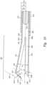
- Figure 7illustrates vertebral column 80 as it may be oriented with the anterior side positioned down and posterior back surface 85 positioned upward, as may be encountered during a spinal procedure or surgery.
- ligamentum flavum 26is thickened/enlarged, resulting in spinal stenosis.
- the anterior portions of enlarged ligamentum flavum 26are extending into spinal canal 81, potentially exerting compressive forces on the spinal cord (not shown) that resides within spinal canal 81.
- outer tubular 210is slid toward and over distal end 260, thereby closing device 200 as previously described.
- tissue 126 within bore 240is severed from the surrounding tissue 126.
- tooth 239 and cutting tip 233slice tissue extending axially from bore 240
- annular cutting edge 211 of outer tubular 210slices tissue extending radially from bore 240 between upper member 231 and lower member 232.
- cutting edge 211 of outer tubular 210is sharpened or beveled to enhance the cutting ability of outer tubular 210.
- Guide tube 330is slidably received in bore 320.
- guide tube 330may be the same component as outer tubular 210 described above with regard to tissue excision device 200 ( Figure 10 ).
- Guide tube 330is preferably sized so that its outer diameter is slightly less than the inside diameter of reduced diameter bore portion 324.
- Guide tube 330has a proximal end 335 and a distal end 337.
- a sleeve 332is preferably affixed to guide tube 330 at or near proximal end 335.
- Sleeve 332preferably includes a trigger-engaging means 333 for engaging trigger 350, as described in detail below.
- Trigger 350has an inner end 355 and an outer end 357.
- Outer end 357preferably includes a finger ring 352 or other similar ergonomic configuration that allows outer end 357 to be easily manually actuated toward grip 314.
- the inner end 355 of trigger 350preferably includes at least one arm 358, which extends adjacent to and beyond guide tube 330.
- arm 358slidably engages trigger-engaging member 333 on guide tube 330.
- Trigger 350is preferably pivotally mounted to housing 310 at a pivot point 359 between its inner and outer ends 355, 357.
- pivot point 358is closer to inner end 355 than it is to outer end 357, so that a mechanical advantage can be employed during operation of the tool.
- a rotation stop 360is preferably provided within cavity 318 and positioned so that it prevents rotation of inner trigger end 355 beyond a certain point.
- tissue clamp 340is provided as a hollow tube or rod.
- tissue ejection system 370may comprise yet another rod or tube 372 (also shown in phantom in Figure 10 ), which is coaxial with and slidably disposed within tissue clamp 340.
- Rod 372is initially positioned so that it extends out of the proximal end of tissue clamp 340 and its distal end 373 is disposed within tissue clamp 340 at a point that is slightly inward of the tissue resection means.
- Tissue ejection system 370may include a plunger head 380 affixed to the proximal end of rod 372.
- Plunger head 380preferably includes a plunger body 382 having distal and proximal ends 385, 387, respectively, and a knob or button 384 affixed to proximal end 387 of plunger body 382.
- a spring 374 or other biasing meansis preferably mounted between the distal end 385 of plunger body 382 and stop 244.
- the outer surface of plunger body 382preferably includes an offset portion 386 defined at its ends by distal and proximal shoulders 387, 388, respectively.
- a pin 389is provided in body 312 and positioned so that it engages offset portion 386. While rod 372 is slidable within body 312, its axial movement in the distal direction is limited by engagement of pin 389 with proximal shoulder 388 and in the proximal direction by distal shoulder 387.
- Spring 274is preferably configured such that it is slightly compressed when pin 389 engages distal shoulder 387.
- plunger head 380is normally urged in the proximal direction so that it extends beyond the proximal end 315 of the device.
- the present multi-function toolallows a surgeon to remove a desired amount of tissue efficiently and precisely.
- the tissue that is to be resectedlies beneath the skin, and possibly within or adjacent to bone.
- access to the resection sitemay be provided by inserting a trocar and cannula (e.g., instrument 101 in Figure 8 ) through the skin and intervening soft tissue as described elsewhere herein.
- the trocarcan be removed, leaving the cannula in place to serve as a portal to the site.
- an ipsilateral techniqueas described elsewhere herein.
- the distal end of the present tool 300is inserted to the resection site as shown in Figure 18 .
- the tissue excision device on the end of tool 300may or may not be open as it passes through the cannula.
- tissue clamp 340includes a tissue excision device (e.g., device 200 shown in Figure 9 ) it will tend to engage, or "bite into” tissue as it advances out of the end of the cannula.
- guide tube 330bears on the outer surface of the tissue excision device (e.g., outer surface of upper member 231 shown in Figure 10 ), urging the tissue excision device into a closed position. As the tissue excision device reaches the closed position, a segment of tissue is resected and retained within the tissue excision device (e.g., within bore 240 shown in Figure 10 ).
- Guide tube 330is advanced by applying pressure in the proximal direction on the outer end 357 of trigger 350. This causes trigger 350 to pivot around point 359, which in turn causes arm 358 to urge sleeve 332 in the distal direction.
- arm 358pivots and shifts relative to sleeve 332.
- the distal end 337 of the guide tubereaches the distal end 347 of the tissue clamp, it is prevented from advancing further by engagement with stop 360.
- tissue ejection system 370may be used to discharge the tissue segment. Tissue ejection system 370 is actuated by applying pressure to knob 384, urging it in the distal direction. As it advances, plunger body 382 advances within the bore or lumen of the tissue excision device (e.g., bore 240 shown in Figure 10 ), compressing spring 374.
- the distal end 373 of the plungeradvances, pushing the tissue segment out as it does so. Once the tissue segment has been ejected, removing pressure from know 384 will allow spring 374 to return the plunger to its normal position, advancing rod 372 in the proximal direction until distal shoulder 387 bears on pin 380.
- tool 300is ready to resect another tissue segment. It will be understood that the steps can be carried out in different sequences, depending on the desired objective. For example, tool 300 can be advanced to the desired resection site in a closed position, rather than an open position.
- the ILAMP methods and techniques described hereinallow spinal decompression to be performed percutaneously, avoiding the pain, lengthy recovery time, and risk associated with open surgery.
- the ILAMP methods and techniques described hereinpermit clearer, less obstructed imaging views of the interlaminar spaces and ligamentum flavum between the laminae in the areas of interest. Such improved imaging views offer the potential for enhanced accuracy and safety in the placement of tools within the ligamentum flavum proximal the epidural space and spinal cord.
- the excision tools and devices described hereinmay be employed with the ILAMP methods, or alternative percutaneous methods, to excise portions of a thickened ligamentum flavum, thereby reducing spinal stenosis caused by such enlarged ligamentum flavum.
- the present devices and techniquesoffer reduced risk of spinal cord damage.
- decompression of the spinal canal in the manner described hereinwill result in improved blood flow to the neural elements by reducing the extrinsic pressure on the spinal vasculature.
- spinal decompression performed according to embodiments of the present inventionwill be preferable to decompression operations performed using currently known techniques.
Landscapes
- Health & Medical Sciences (AREA)
- Life Sciences & Earth Sciences (AREA)
- Surgery (AREA)
- General Health & Medical Sciences (AREA)
- Veterinary Medicine (AREA)
- Engineering & Computer Science (AREA)
- Biomedical Technology (AREA)
- Heart & Thoracic Surgery (AREA)
- Public Health (AREA)
- Animal Behavior & Ethology (AREA)
- Medical Informatics (AREA)
- Molecular Biology (AREA)
- Orthopedic Medicine & Surgery (AREA)
- Nuclear Medicine, Radiotherapy & Molecular Imaging (AREA)
- Oral & Maxillofacial Surgery (AREA)
- Dentistry (AREA)
- Hematology (AREA)
- Anesthesiology (AREA)
- Vascular Medicine (AREA)
- Pathology (AREA)
- Surgical Instruments (AREA)
- Prostheses (AREA)
- Medicines Containing Plant Substances (AREA)
- Media Introduction/Drainage Providing Device (AREA)
- Infusion, Injection, And Reservoir Apparatuses (AREA)
Description
- The present invention relates to a kit for treating spinal stenosis.
- The vertebral column (spine, spinal column, backbone) forms the main part of the axial skeleton, provides a strong yet flexible support for the head and body, and protects the spinal cord disposed in the vertebral canal, which is formed within the vertebral column. The vertebral column comprises a stack of vertebrae with an intervertebral disc between adjacent vertebrae. The vertebrae are stabilized by muscles and ligaments that hold the vertebrae in place and limit the movements of the vertebrae.
- As illustrated in
Figure 1 , eachvertebra 10 includes avertebral body 12 that supports avertebral arch 14. Amedian plane 210 generally dividesvertebra 10 into two substantially equal lateral sides.Vertical body 12 has the general shape of a short cylinder and is anterior to thevertebral arch 14. Thevertebral arch 14 together withvertebral body 12 encloses a space termed thevertebral foramen 15. The succession ofvertebral foramen 15 inadjacent vertebrae 10 along the vertebral column define the vertebral canal (spinal canal), which contains the spinal cord.Vertebral arch 14 is formed by twopedicles 24 which project posteriorly to meet twolaminae 16. The twolaminae 16 meet posteriomedially to form thespinous process 18. At the junction ofpedicles 24 andlaminae 16, six processes arise. Twotransverse processes 20 project posterolaterally, two superiorarticular processes 22 project generally superiorly and are positioned superior to two inferiorarticular processes 25 that generally project inferiorly. - The
vertebral foramen 15 is generally an oval shaped space that contains and protects thespinal cord 28.Spinal cord 28 comprises a plurality ofnerves 34 surrounded by cerebrospinal fluid (CSF) and an outermost sheath/membrane called thedural sac 32. The CSF filleddural sac 32 containingnerves 34 is relatively compressible. Posterior to thespinal cord 28 withinvertebral foramen 15 is theligamentum flavum 26.Laminae 16 of adjacentvertebral arches 14 in the vertebral column are joined by the relatively broad,elastic ligamentum flavum 26. - In degenerative conditions of the spine, narrowing of the spinal canal (stenosis) can occur. Lumbar spinal stenosis is often defined as a dural sac cross-sectional area less than 100 mm2 or an anterior-posterior (AP) dimension of the canal of less than 10-12 mm for an average male.
- The source of many cases of lumbar spinal stenosis is thickening of the ligamentum flavum. Spinal stenosis may also be caused by subluxation, facet joint hypertrophy, osteophyte formation, underdevelopment of spinal canal, spondylosis deformans, degenerative intervertebral discs, degenerative spondylolisthesis, degenerative arthritis, ossification of the vertebral accessory ligaments and the like. A less common cause of spinal stenosis, which usually affects patients with morbid obesity or patients on oral corticosteroids, is excess fat in the epidural space. The excessive epidural fat compresses the dural sac, nerve roots and blood vessels contained therein and resulting in back, leg pain and weakness and numbness of the legs. Spinal stenosis may also affect the cervical and, less commonly, the thoracic spine.
- Patients suffering from spinal stenosis are typically first treated with exercise therapy, analgesics, and anti-inflammatory medications. These conservative treatment options frequently fail. If symptoms are severe, surgery is required to decompress the spinal cord and nerve roots.
- In some conventional approaches to correct stenosis in the lumbar region, an incision is made in the back and the muscles and supporting structures are stripped away from the spine, exposing the posterior aspect of the vertebral column. The thickened ligamentum flavum is then exposed by removal of a portion of the vertebral arch, often at the laminae, covering the back of the spinal canal (laminectomy). The thickened ligamentum flavum ligament can then be excised by sharp dissection with a scalpel or punching instruments such as a Kerison punch that is used to remove small chips of tissue. The procedure is performed under general anesthesia. Patients are usually admitted to the hospital for approximately five to seven days depending on the age and overall condition of the patient. Patients usually require between six weeks and three months to recover from the procedure. Further, many patients need extended therapy at a rehabilitation facility to regain enough mobility to live independently.
- Much of the pain and disability after an open laminectomy results from the tearing and cutting of the back muscles, blood vessels, supporting ligaments, and nerves that occurs during the exposure of the spinal column. Also, because the spine stabilizing back muscles and ligaments are stripped and detached from the spine during the laminectomy, these patients frequently develop spinal instability postoperatively.
- Minimally invasive techniques offer the potential for less post-operative pain and faster recovery compared to traditional open surgery. Percutaneous interventional spinal procedures can be performed with local anesthesia, thereby sparing the patient the risks and recovery time required with general anesthesia. In addition, there is less damage to the paraspinal muscles and ligaments with minimally invasive techniques, thereby reducing pain and preserving these important stabilizing structures.
- Various techniques for minimally invasive treatment of the spine are known. Microdiscectomy is performed by making a small incision in the skin and deep tissues to create a portal to the spine. A microscope is then used to aid in the dissection of the adjacent structures prior to discectomy. The recovery for this procedure is much shorter than traditional open discectomies. Percutaneous discectomy devices with fluoroscopic guidance have been used successfully to treat disorders of the disc but not to treat spinal stenosis or the ligamentum flavum directly. Arthroscopy or direct visualization of the spinal structures using a catheter or optical system have also been proposed to treat disorders of the spine including spinal stenosis, however these devices still use miniaturized standard surgical instruments and direct visualization of the spine similar to open surgical procedures. These devices and techniques are limited by the small size of the canal and these operations are difficult to perform and master. In addition, these procedures are painful and often require general anesthesia. Further, the arthroscopy procedures are time consuming and the fiber optic systems are expensive to purchase and maintain.
- Still further, because the nerves of the spinal cord pass through the spinal canal directly adjacent to and anterior to the ligamentum flavum, any surgery, regardless of whether open or percutaneous, includes a risk of damage to the nerves of the spinal cord.
- Hence, it remains desirable to provide simple devices for treating spinal stenosis and other spinal disorders without requiring open surgery. It is further desired to provide a system whereby the risk of damage to the dural sac containing the spinal nerves may be reduced.
US 2001/029370 A1 relates to systems, apparatus and methods for ablation, resection, aspiration, collagen shrinkage and/or hemostasis of tissue and other body structures in open and endoscopic spine surgery.US 2002/091387 A1 provides a method of and an apparatus for removing bone, capsule ligaments from a co-operating pair of superior and inferior articulating processes (also called facet joints) of the spine to create a path for postero-lateral endoscopic access to the vertebral foramen and to the epidural space of the spinal canal.WO 2006/015302 A1 discloses a method for treating stenosis in a spine which comprises percutaneously accessing the epidural space in a stenotic region of interest.WO 96/22056 A1 US 5 637 096 A discloses a safety needle including an elongate, tubular needle and a safety probe movable therein between an extended position with a blunt distal end of the safety probe projecting distally of the needle distal end and a retracted position with the safety probe distal end disposed proximally of the needle distal end.- Further prior art is disclosed in
US 5 226 426 A ,WO 2008/002900 A2 ,US 6 264 650 B1WO 96/29936 A1 WO 98/40015 A2 - These and other needs in the art are addressed by a kit for treating spinal stenosis as it is defined in claim 1.
- Thus, embodiments described herein comprise a combination of features and advantages intended to address various shortcomings associated with certain prior devices. The various characteristics described above, as well as other features, will be readily apparent to those skilled in the art upon reading the following detailed description of the preferred embodiments, and by referring to the accompanying drawings.
- For a more complete understanding of the invention, reference is made to the accompanying drawings, wherein:
Figure 1 is cross-section of the spine viewed from the space between two vertebrae, showing the upper surface of one vertebra and the spinal canal with the dural sac and a normal (un-stenosed) ligamentum flavum therein;Figure 2 is an illustration of the same section asFigure 1 , showing the spinal canal with the dural sac and a thickened ligamentum flavum therein;Figure 3 is an enlarged cross-section of a vertebral foramen, showing a safety zone created by compression of the dural sac;Figure 4 is the cross-section ofFigure 3 , showing a tissue excision tool positioned in the ligamentum flavum according to a first method (ILAMP);Figure 5 is the cross-section ofFigure 3 , showing a tissue excision tool positioned in the ligamentum flavum according to an alternative method (MILD);Figure 6 is a partial cross-section of the lumbar portion of the vertebral column taken along lines 6-6 inFigure 1 ;Figure 7 is the cross-section ofFigure 6 , showing the orientation of an imaging tool relative to the vertebral column;Figure 8 is the cross-section ofFigure 6 , showing the orientation of an instrument relative to the vertebral column;Figure 9 is a perspective view of the distal portion of an embodiment of a tissue excision device in an open positionFigure 10 is a cross-sectional view of the tissue excision device illustrated inFigure 9 ;Figures 11-13 are series of side views of the tissue excision device illustrated inFigure 9 transitioning from an open position to a closed position;Figures 14 and 15 are sequential illustrations showing the excision of tissue by the tissue, excision tool illustrated inFigure 9 ;Figure 16 is a perspective view of the distal portion of non-claimed example of a tissue excision device in an open position;Figure 17 is a partial cut-away view of an embodiment of a tissue ejection device; andFigure 18 is a schematic cross-section showing one embodiment of the present tool inserted into tissue via a cannula.- The following discussion is directed to various embodiments of the invention. Although one or more of these embodiments may be preferred, the embodiments disclosed should not be interpreted, or otherwise used, as limiting the scope of the disclosure, including the claims. In addition, one skilled in the art will understand that the following description has broad application, and the discussion of any embodiment is meant only to be exemplary of that embodiment, and not intended to intimate that the scope of the disclosure, including the claims, is limited to that embodiment.
- For purposes of this discussion, the x-, y-, and z-axes are shown in
Figures 1 ,3 ,5 ,6 , and7 to aid in understanding the descriptions that follow. The x-, y-, and z-axes have been assigned as follows. The x-axis is perpendicular to the longitudinal axis of the vertebral column and perpendicular to the coronal/frontal plane (i.e., x-axis defines anterior vs. posterior relationships). The y-axis runs substantially parallel to the vertebral column and perpendicular to the transverse plane (i.e., y-axis defines superior vs. inferior relationships). The z-axis is perpendicular to the longitudinal axis of the vertebral column and perpendicular to the median/midsagittal plane (i.e., z-axis defines the lateral right and left sides of body parts). The set of coordinate axes (x-, y-, and z-axes) are consistently maintained throughout although different views of vertebrae and the spinal column may be presented. - It is to be understood that the median/midsagittal plane passes from the top to the bottom of the body and separates the left and the right sides of the body, and the spine, into substantially equal halves (e.g., two substantially equal lateral sides). Further, it is to be understood that the frontal/coronal plane essentially separates the body into the forward (anterior) half and the back (posterior) half, and is perpendicular to the median plane. Still further, it is to be understood that the transverse plane is perpendicular to both the median plane and coronal plane and is the plane which divides the body into an upper and a lower half
- Referring again to
Figure 1 ,vertebral foramen 15 contains a portion of the ligamentum flavum 26,spinal cord 28, and anepidural space 27 between ligamentum flavum 26 andspinal cord 28.Spinal cord 28 comprises a plurality ofnerves 34 surrounded by cerebrospinal fluid (CSF) contained withindural sac 32.Nerves 34 normally comprise only a small proportion of thedural sac 32 volume. Thus, CSF filleddural sac 32 is somewhat locally compressible, as localized pressure causes the CSF to flow to adjacent portions of the dural sac.Epidural space 27 is typically filled with blood vessels and fat. The posterior border of the normalepidural space 27 generally defined by theligamentum flavum 26, which is shown in its normal, non-thickened state inFigure 1 . Figure 2 illustrates a case of spinal stenosis resulting from a thickenedligamentum flavum 26. Sincevertebral foramen 15 is defined and surrounded by the relatively rigid bone its volume is essentially constant. Thus, thickening of ligamentum flavum 26 withinvertebral foramen 15 can eventually result in compression ofspinal cord 28. In particular, the thickenedligamentum flavum 26 may exert a compressive force on the posterior surface ofdural sleeve 32. In addition, thickening of ligamentum flavum 26 may compress the blood vessels and fat occupyingepidural space 27.- Compression of
spinal cord 28, particularly in the lumbar region, may result in low back pain as well as pain or abnormal sensations in the legs. Further, compression of the blood vessels in theepidural space 27 that houses the nerves of the cauda equina may result in ischemic pain termed spinal claudication. - In order to relieve the symptoms associated with a thickened or enlarged ligamentum flavum 26, methods, techniques, and devices described herein may be employed to reduce the compressive forces exerted by the thickened ligamentum flavum on
spinal cord 28 and the blood vessels in epidural space 27 (e.g., decompressspinal cord 28 and blood vessels in epidural space 27). In particular, compressive forces exerted by the thickened/enlarged ligamentum flavum 26 may be reduced by embodiments of a minimally invasive ligament decompression (MILD) procedure described herein. In some embodiments, the MILD procedure may be performed percutaneously to reduce the size of ligamentum flavum 26 by excising portions of ligamentum flavum 26. In particular, in some embodiments of the MILD procedure, the ligamentum flavum 26 is accessed, cut and removed ipsilaterally (i.e., on the same side of vertebral arch 14) by a percutaneous cranial-caudal approach. Such an embodiment of the MILD procedure may be described hereinafter as Ipsilateral Approach MILD Procedure (ILAMP). - As shown in
Figures 1 and 2 ,ligamentum flavum 26 is posteriorly apposed tospinal cord 28. Thus, placement of tools within ligamentum flavum 26 to excise portions of ligamentum flavum 26 creates a risk of for inadvertent damage to thespinal cord 28,dural sac 32, and/ornerves 34. Thus, in preferred embodiments of the procedures described herein, prior to insertion of tissue excision devices into theligamentum flavum 26, a gap is advantageously created between ligamentum flavum 26 andspinal cord 28 to provide a safety zone between ligamentum flavum 26 andspinal cord 28. Figure 3 illustrates an enlarged cross-sectional view of avertebral foramen 15 within a vertebra.Vertebral foramen 15 includesepidural space 27 andspinal cord 28 containingnerves 34 and CSF withindural sac 32. Further, a thickened/enlarged ligamentum flavum 26 extends intovertebral foramen 15. To reduce the risk of damage todural sac 32 andspinal cord 28, asafety zone 40 is created between ligamentum flavum 26 anddural sac 32.- As previously described,
spinal cord 28 comprisesnerves 34 surrounded by CSF and is contained withindural sac 32. Since more than 90% of the volume ofdural sac 32 in the lumbar region is filled by CSF,dural sac 32 is highly compressible. Thus, even when stenosis is causing compression ofspinal cord 28, in most cases it is possible to temporarily compressspinal cord 28 further. Thus, according to preferred embodiments,dural sac 32 is further compressed in the region of interest by injecting a fluid intoepidural space 27 to createsafety zone 40. The fluid may be injected into theepidural space 27 with an insertion member, such as a needle. The presence of the injected fluid comprisingsafety zone 40 gently applies an additional compressive force to the outer surface ofdural sac 32 so that at least a portion of the CSF withindural sac 32 is forced out ofdural sac 32 in the region of interest, resulting insafety zone 40 betweendural sac 32 andligamentum flavum 26. - According to some embodiments,
dural sac 32 is compressed by injecting a standard radio-opaque non-ionic myelographic contrast medium or other imagable or nonimagable medium intoepidural space 27 in the region of interest. This is preferably accomplished with a percutaneous injection. Sufficient injectable fluid is preferably injected to displace the CSF out of the region of interest and compressdural sac 32 to at least a desired degree. The injected medium is preferably substantially contained within the confines ofepidural space 27 extending to the margins of thedural sac 32. The epidural space is substantially watertight and the fatty tissues and vascularization inepidural space 27, combined with the viscous properties of the preferred fluids, serve to substantially maintain the injected medium in the desired region of interest. This novel method for protectingspinal cord 28 column may be referred to hereinafter as "contrast-guided dural protection." - Once a
safety zone 40 has been created, a tissue excision tool ordevice 100 may be inserted into theligamentum flavum 26.Device 100 may comprise any suitable device, tool or instrument for relieving stenosis caused by the thickened/enlarged ligamentum flavum 26 including without limitation, embodiments of tissue excision devices and tissue retraction devices described in more detail below. Further, as best illustrated inFigure 4 ,device 100 is inserted and positioned in theligamentum flavum 26 on the same side (ipsilateral) ofmedian plane 210 asdevice 100 percutaneously accesses the body, such thatdevice 100 does not crossmedian plane 210. In another embodiment, as best illustrated inFigure 4 ,device 100 is positioned in theligamentum flavum 26 on the opposite side ofmedian plane 210 asdevice 100 percutaneously accesses the body, such thatdevice 100 crossesmedian plane 210. In some embodiments,tissue excision device 100 may be guided by and advanced through a cannula toward theligamentum flavum 26. In other embodiments, a cannula is not be employed to guidedevice 100 as it is advanced towardligamentum flavum 26. - While it is preferred that the tip of
device 100 remain within ligamentum flavum 26 as shown, the presence ofsafety zone 40 reduces the likelihood thatdural sac 32 will be damaged, even if the tip ofdevice 100 breaks through the anterior surface of ligamentum flavum 26. - Because the present techniques are preferably performed percutaneously, certain aspects of the present invention may be facilitated by imaging. Imaging windows (e.g., a fluoroscopic window of access - FWA) may be employed to aid in performance of all or part of the procedures described herein. For instance, an imaging window may be employed to aid in insertion of
device 100 intoligamentum flavum 26 as shown inFigure 4 . Preferable imaging windows/views are described in more detail below. - In this context, the spine can be imaged using any suitable technology, including without limitation, 2D fluoroscopy, 3D fluoroscopy, CT, MRI, ultrasound or with direct visualization with fiber optic or microsurgical techniques. Stereotactic or computerized image fusion techniques are also suitable. Fluoroscopy is currently particularly well-suited to the techniques disclosed herein. Fluoroscopic equipment is safe and easy to use, readily available in most medical facilities, relatively inexpensive. In a typical procedure, using direct biplane fluoroscopic guidance and local anesthesia,
epidural space 27 is accessed for injection of contrast media adjacent to the surgical site. - If the injected medium is radio-opaque, as are for example myelographic contrast media, the margins of expanded
epidural space 27 will be readily visible using fluoroscopy or CT imaging. Thus,safety zone 40 created by the present contrast-guided dural compression techniques can reduce the risk of damage todural sac 32 andspinal cord 28 during MILD procedures to remove or displace portions of ligamentum flavum 26 and/orlaminae 16 in order to treat spinal stenosis. - If desired, the injected medium can be provided as a re-absorbable water-soluble gel, so as to better localize
safety zone 40 at the site of surgery and reduce leakage of this protective layer from the vertebral/spinal canal. An injectable gel is a significant improvement on prior epidural injection techniques. The gel is preferably substantially more viscid than conventional contrast media and the relatively viscid and/or viscous gel preferably tends to remain localized at the desired site of treatment as it does not spread as much as standard liquid contrast media that are used in epidurography. This may result in more uniform compression ofdural sac 32 and less leakage of contrast out of the vertebral/spinal canal. In addition, preferred embodiments of the gel are re-absorbed more slowly than conventional contrast media, allowing for better visualization during the course of the surgical procedure. - In some embodiments, a contrast agent can be included in the gel itself, so that the entire gel mass is imagable. In other embodiments, an amount of contrast can be injected first, followed by the desired amount of gel, or an amount of gel can be injected first, followed by the desired amount of contrast. In this case, the contrast agent is captured on the surface of the expanding gel mass, so that the periphery of the mass is imagable.
- Any standard hydrophilic-lipophilic block copolymer (Pluronic) gel such as are known in the art would be suitable and other gels may be used as the injectable medium. The gel preferably has an inert base. In certain embodiments, the gel material is liquid at ambient temperatures and can be injected through a small bore, such as a 27 gauge needle. The gel then preferably becomes viscous when warmed to body temperature after being injected. The viscosity of the gel can be adjusted through the specifics of the preparation. The gel or other fluid is preferably sufficiently viscid or viscous at body temperature to compress and protect
dural sac 32 in the manner described above and to remain sufficiently present in the region of interest for at least about 30 minutes. Thus, in some embodiments, the injected gel attains a viscosity that is two, three, six or even ten times that of the fluids that are typically used for epidurograms. - In certain embodiments, the injected medium undergoes a reversible change in viscosity when warmed to body temperature so that it can be injected as a lowviscosity fluid, thicken upon injection into the patient, and be returned to its lowviscosity state by cooling. In these embodiments, the injected medium is injected as desired and thickens upon warming, but can be removed by contacting it with a heat removal device, such as an aspirator that has been provided with a cooled tip. As a result of localized cooling, the gel reverts to its initial non viscous liquid state and can be easily suctioned up the cooled needle or catheter.
- An example of a suitable contrast medium having the desired properties is
Omnipaque ® 240 available from Nycomed, New York, which is a commercially available non-ionic iodinated myelographic contrast medium. Other suitable injectable media will be known to those skilled in the art. Because of the proximity tospinal cord 28 andspinal nerves 34, it is preferred not to use ionic media in the injectable medium. The preferred compositions are reabsorbed relatively rapidly after the procedure. Thus any residual gel compression ondural sac 32 after the MILD procedure dissipates relatively quickly. For example, in preferred embodiments, the gel would have sufficient viscosity to compressdural sac 32 for thirty minutes, and sufficient degradability to be substantially reabsorbed within approximately two hours. - The injected contrast medium further may further include one or more bioactive agents. For example, medications such as those used in epidural steroid injection (e.g. Depo medrol, Celestone Soluspan) may be added to the epidural gel to speed healing and reduce inflammation, scarring and adhesions. The gel preferably releases the steroid medication slowly and prolongs the anti-inflammatory effect, which can be extremely advantageous. Local anesthetic agents may also be added to the gel. This prolongs the duration of action of local anesthetic agents in the epidural space to prolong pain relief during epidural anesthesia. In this embodiment the gel may be formulated to slow the reabsorption of the gel.
- The present gels may also be used for epidural steroid injection and perineural blocks for management of acute and chronic spinal pain. Thrombin or other haemostatic agents can be added if desired, so as to reduce the risk of bleeding.
- In some embodiments, the gel may also be used as a substitute for a blood patch if a CSF leak occurs. The gel may also be used as an alternative method to treat lumbar puncture complications such as post-lumbar puncture CSF leak or other causes of intracranial hypotension. Similarly, the gel may be used to patch postoperative CSF leaks or dural tears. If the dural sac were inadvertently tom or cut, then gel could immediately serve to seal the site and prevent leakage of the cerebral spinal fluid.
- Once
safety zone 40 has been created, the margins ofepidural space 27 are clearly demarcated by the injected medium and may be visualized radiographically if an imageable medium has been used. As mentioned above, percutaneous procedures can then more safely be performed onligamentum flavum 26 and/or surrounding tissues with reduced potential for injuringdural sac 32 andspinal cord 28. - A variety of suitable techniques and devices may be employed to reduce the size of the thickened/
enlarged ligamentum flavum 26, thereby decompressingspinal cord 28 as well as blood vessels contained within theepidural space 27. Examples of suitable decompression techniques include without limitation, removal of tissue from ligamentum flavum 26, laminectomy, laminotomy, and retraction and anchoring of ligamentum flavum 26. In some embodiments, all or a portion of ligamentum flavum 26 is excised using a tissue excision device or tool (e.g., device 100). Embodiments of tissue excision tools are described in more detail below. - Accessing ligamentum flavum 26 with a
tissue excision device 100 to remove portions of ligamentum flavum 26 can present significant challenges. For instance, in some conventional approaches to correct stenosis caused by an enlarged ligamentum flavum, an incision is made in the back of the patient and then the muscles and supporting structures of the vertebral column (spine) are stripped away, exposing the posterior aspect of the vertebral column. Subsequently, the thickened ligamentum flavum is exposed by removal of a portion ofvertebral arch 14, often atlamina 16, which encloses the anterior portion of the spinal canal (laminectomy). The thickened ligamentum flavum ligament can then be excised by sharp dissection with a scalpel or punching instruments. However, this approach is usually performed under general anesthesia and typically requires an extended hospital stay, lengthy recovery time and significant rehabilitation. Referring briefly toFigure 2 , as another example, some MILD proceduresaccess ligamentum flavum 26 percutaneously by boring a hole through thevertebral arch 14 ofvertebra 10, often through alamina 16. A cannula and/ordevice 100 may be passed through the bore and/or anchored to the bore to accessligamentum flavum 26 for excision. However, while such a MILD approach is minimally invasive and reduces recovery time, such an approach requires the additional step of boring a hole in the posterior of thevertebra 10 of interest. Thus, in some cases it will be preferable to employ a MILD that percutaneously accessesligamentum flavum 26 without the need to cut or bore through the vertebrae. Figure 6 is a partial cross-sectional lateral view of a segment of avertebral column 80. The segment ofvertebral column 80 illustrated inFigure 5 includes threevertebrae vertebra vertebral body vertebral arch Vertical body vertebral arch vertebral arch vertebral body adjacent vertebrae vertebral column 80.Vertebral canal 81 contains the spinal cord (not shown inFigure 5 ).- As previously described, each
vertebral arch pedicles lamina vertebra lamina lamina spinous process Lamina adjacent vertebra lamina 16a ofsuperior vertebra 10a and connects to the superior surface of lamina 16b of theinferior vertebra 10b. Thus,ligamentum flavum 26 spans an interlaminar space 82 (i.e., space between laminae of adjacent vertebrae).Interlaminar space 82 is generally the space between laminae of adjacent vertebrae inspinal column 80.- Still referring to
Figure 6 , eachlamina pedicles vertebral column 80, thelamina interlaminar space 82. For instance,lamina 16a is substantially parallel to and partially overlaps adjacent inferior lamina 16b and is separated from lamina 16b byligamentum flavum 26 andinterlaminar space 82. Figure 7 illustratesvertebral column 80 as it may be oriented with the anterior side positioned down andposterior back surface 85 positioned upward, as may be encountered during a spinal procedure or surgery. In addition, in the embodiment illustrated inFigure 6 ,ligamentum flavum 26 is thickened/enlarged, resulting in spinal stenosis. In particular, the anterior portions of enlarged ligamentum flavum 26 are extending intospinal canal 81, potentially exerting compressive forces on the spinal cord (not shown) that resides withinspinal canal 81.- As previously discussed, to relieve compressive forces on the spinal cord and hence relieve the associated symptoms of spinal stenosis, portions of ligamentum flavum 26 may be excised. However, to percutaneously excise portions of ligamentum flavum 26 via minimally invasive techniques, the innate structure of
vertebral column 80 and each vertebra may present significant imaging challenges. For instance, lateral imaging windows/views of ligamentum flavum 26 substantially in the direction of the z-axis may be obscured by the various processes of the vertebrae (e.g., transverse processes, superior articular processes, inferior articular processes), the laminae of each vertebra, etc. Further, some anterior-posterior (A-P) imaging windows/views of ligamentum flavum 26 substantially in the direction of the x-axis may also be obscured by the laminae. In particular, in the A-P radiographic imaging planes substantially in the direction of the x-axis, the posterior edges of parallel laminae overlap and obscure ligamentum flavum 26 andinterlaminar space 82, particularly the anterior portions of ligamentum flavum 26 andinterlaminar space 82 closest tospinal canal 81. However, with an imaging window/view in a plane substantially parallel to the X-Y plane, at an angle θ generally in the direction ofarrow 83, and slightly lateral to the spinous process,interlaminar space 82 andligamentum flavum 26 may be viewed without significant obstruction from neighboring laminae. In other words, imaging windows/views generally aligned with arrow 83 (Figure 6 ) allow a more direct view ofinterlaminar space 82 andligamentum flavum 26 from the posterior back surface with minimal obstruction by the vertebrae, laminae in particular. - Typically, the long axes of the substantially parallel laminae (e.g.,
laminae surface 85. Thus, preferably the imaging means (e.g., x-ray beam, fluoroscopy tube, etc.) is positioned generally in the direction represented byarrow 83, where θ is substantially between 60 and 75 degrees relative to theanterior back surface 85. In other words, the imaging means is positioned substantially parallel to the surface of the laminae. The resulting imaging window/view, termed "caudal-cranial posterior view" hereinafter, permits a clearer, more direct, less obstructed view ofinterlaminar space 82 andligamentum flavum 26 from the general posterior backsurface 85. The caudal-cranial posterior view permits a relatively clear view ofinterlaminar space 82 andligamentum flavum 26 in directions generally along the y-axis and z-axis. However, the caudal-cranial posterior view by itself may not provide a clear imaging window/view ofinterlaminar space 82 andligamentum flavum 26 in directions generally along the x-axis. In other words, the caudal-cranial posterior view by itself may not provide a clear imaging window/view that can be used to accurately determine the posterior-anterior depth, measured generally along the x-axis, of a device across theligamentum flavum 26. - Thus, in preferred embodiments, an additional imaging window/view, termed "caudal-cranial posterior-lateral view" hereinafter, is employed to provide a clearer, unobstructed view of
interlaminar space 82 andligamentum flavum 26 in directions generally along the y-axis and z-axis. The caudal-cranial posterior-lateral view is generated by orienting an imaging means generally at an angle θ relative to outer surface of the patient and also angling such imaging means laterally in an oblique orientation, revealing a partial lateral view ofinterlaminar space 82 occupied byligamentum flavum 26 on the anterior side of the lamina and posterior to the underlying dural sac (not shown) and spinal cord (not shown). - By employing at least one of the caudal-cranial posterior view and the caudal-cranial posterior-lateral views, relatively clear imaging windows/views of the
interlaminar space 82 andligamentum flavum 26 in directions along the x-, y-, and z-axes may be achieved. Figure 8 illustratesvertebral column 80 and aninstrument 101. Once unobstructed imaging windows/views ofinterlaminar space 82 andligamentum flavum 26 are established in the manner described above,instrument 101 is employed to percutaneously accessinterlaminar space 82 andligamentum flavum 26.Instrument 101 may be any suitable device necessary to perform the MILD procedures described herein including without limitation a tissue excision device, a cannula employed to guide a tissue excision device, or combinations thereof. Tissue excision tools and devices are described in more detail below.- More specifically, using images of the
interlaminar space 82 andligamentum flavum 26 obtained from the desired direction(s), (e.g., caudal-cranial posterior view and the caudal-cranial posterior-lateral view),instrument 101 can be employed to penetrate the skin and soft tissue in the posterior backsurface 85 of the patient. In preferred embodiments, the skin entry point forinstrument 101 is between 5 and 10 cm inferior (caudal to) the posterior surface of theinterlaminar space 82 of interest. For instance, if the portion of ligamentum flavum 26 betweenlamina 16a and lamina 16b is the area of interest, theninstrument 101 may be inserted into the patient's back about 5 to 10 cm inferior to posterior surface 84 ofinterlaminar space 82. - Referring now to
Figure 7 ,instrument 101 is preferably initially inserted into the posterior tissue and musculature of the patient generally parallel to the longitudinal axis ofspinal column 80. In other words, the angle β between the posterior backsurface 85 andinstrument 101 is between 0 and 10 degrees wheninstrument 101 is initially inserted. Further,instrument 101 is preferably inserted into the posterior tissue and musculature of the patient on the same side (ipsilateral) of the median plane as the area of interest (e.g., the targeted portion of ligamentum flavum 26), as best seen inFigure 4 . Onceinstrument 101 is inserted into the posterior tissue and musculature of the patient,instrument 101 then may be oriented 5 to 90 degrees relative to the posterior backsurface 85 in order to create a trajectory across ligamentum flavum 26 in the area of interest. It is to be understood that onceinstrument 101 is inserted into the patients posterior backsurface 85, the ends ofinstrument 101 are free to pivot about the insertion location in posterior backsurface 85 in the general direction of the y-axis and the z-axis, and may be advanced posteriorly or anteriorly generally in the direction of the x-axis. - Once inserted into the posterior tissue and musculature of the patient,
instrument 101 can be positioned to provide a trajectory acrossinterlaminar space 82 in the area of interest, generally towards the anterior surface of the lamina superior to the area of interest. For example, ifinterlaminar space 82 betweenlamina 16a and lamina 16b is the area of interest,instrument 101 is positioned to provide a trajectory that will allow a cutting instrument to be inserted acrossinterlaminar space 82 betweenlamina 16a and lamina 16b towards the anterior surface oflamina 16a (superior lamina). - By switching between the caudal-cranial posterior view and the caudal-cranial posterior-lateral view, or by viewing both the caudal-cranial posterior view and the caudal-cranial posterior-lateral view at the same time,
instrument 101 can be advanced to ligamentum flavum 26 in the area of interest with more certainty than has heretofore been present. Onceinstrument 101 has reached ligamentum flavum 26, portions of ligamentum flavum 26 may be excised with a tissue excision device so as to relieve pressure on the spinal nerves. Ifinstrument 101 comprises a tissue excision tool,instrument 101 may be inserted intoligamentum flavum 26 to resect portions of ligamentum flavum 26. However, ifinstrument 101 comprises a cannula,instrument 101 will be positioned adjacent the ligamentum flavum 26 in the region of interest and a tissue excision device may be advanced throughinstrument 101 towardligamentum flavum 26 and inserted inligamentum flavum 26 in the region of interest to retract tissue therefrom. In some embodiments, excision can be performed generally from posterior to anterior acrossinterlaminar space 82 and then laterally along the anterior portion of ligamentum flavum 26 if desired. The actual depth of the tip of instrument 101 (or any tissue excision device passing throughinstrument 101 in thecase instrument 101 is a cannula) in the general direction of the x-axis may be adjusted with guidance from the caudal-cranial posterior-lateral view and appropriate retraction/advancement ofinstrument 101 and appropriate adjustment ofinstrument 101 between 5 and 90 degrees relative to the posterior back surface 8 5. - Referring to
Figure 4 , the tip of an exemplarytissue excision device 100 is shown schematically withinligamentum flavum 26.Tissue excision device 100 may be the same device asinstrument 101, or may be a tool passed throughinstrument 101 ifinstrument 101 is a cannula. In particular,device 100 has accessedligamentum flavum 26 according to the ILAMP method previously described. Thus,device 100 is positioned to excise portions of ligamentum flavum 26 on the same lateral side ofmedian plane 210 asdevice 100 is percutaneously inserted. In other words, in the view shown inFigure 4 ,device 100 is inserted into the body on the right side ofmedian plane 210 and entersligamentum flavum 26 on the right side ofmedian plane 210 to excise portions of ligamentum flavum 26 on the right side ofmedian plane 210. InFigure 4 ,device 100 does not crossmedian plane 210. Figure 5 illustrates an embodiment of an alternative MILD method in which exemplarytissue excision device 100 is positioned to excise portions of ligamentum flavum 26 on the opposite lateral side ofmedian plane 210 asdevice 100 is percutaneously inserted. More specifically,device 100 is inserted into the body on the rights side ofmedian plane 210, entersligamentum flavum 26 on the right side ofmedian plane 210, but is positioned to excise portions of ligamentum flavum 26 on the left side ofmedian plane 210. InFigure 5 ,device 100 crossesmedian plane 210.- In the manner described, portions of the ligamentum flavum can be excised by a percutaneous MILD procedure. In particular, with the approach described and as best illustrated in
Figures 4 and6 ,ligamentum flavum 26 can be accessed, and portions thereof removed via the interlaminar space on the same lateral side (ipsilateral) ofmedian plane 210 as the entry point for instrument 101 (e.g., a cannula, a tissue excision tool, etc.). This approach may sometimes hereinafter be referred to as an Iplsilateral Approach MILD Procedure (ILAMP). - Embodiments of tissue excision tools, devices, and methods disclosed herein may take several forms and may be used according to the ILAMP method described above, or used according to alternative MILD procedures (e.g., MILD procedure schematically illustrated in
Figure 5 ). One such alternative MILD procedure is disclosed inUS-A-2006-0036272 (U.S. Application Serial No. 11/193,581 ). In the descriptions of the tissue excision devices below, the distal portions of the devices are described in detail. As used herein, the term "distal" refers to positions that are relatively closer to the region of interest (e.g., the thickened portion of the ligamentum flavum to be decompressed). An exemplary embodiment of a proximal end for the tissue excision devices, including an actuation means, is also described below. Figures 9 and10 illustrate the distal portion of an embodiment of atissue excision device 200 in an opened position.Tissue excision device 200 comprises an innertubular member 230 coaxially disposed within and slidingly engaging an outertubular member 210. Inner and outertubular members longitudinal axis 250.Outer member 210 has an inner radius R1, as measured fromaxis 250, andinner member 230 has an outer radius R2, as measured fromaxis 250. In this embodiment, outer radius R2 is substantially the same or slightly less than inner radius R1 such that the outer surface of inner tubular 230 slidingly engages the inner surface oftubular 210. Thus,outer tubular 210 andinner tubular 230 are permitted to move axially (i.e., along axis 250) relative to each other.Tubulars tubulars Figures 9 and10 generally have a circular cross-section, in general,members - Inner tubular 230 includes a central through
bore 240 and adistal end 260. Bore 240 runs the length ofinner tubular 230 and provides a void or space that may be filled with tissue excised by device 200 (e.g., excised pieces of ligamentum flavum).Distal end 260 includes anupper member 231 and alower member 232.Distal end 260, includingupper member 231 andlower member 232, completely extends from outer tubular 210 whendevice 200 is in the opened position as illustrated inFigures 9 and10 .Upper member 231 andlower member 232 are preferably integral with and formed frominner tubular 230. In such embodiments,distal end 260 of inner tubular 230 may be formed into anupper member 231 andlower member 232 by any suitable means including without limitation casting or molding, laser cutting, machining, hot or cold working, or combinations thereof. Lower member 232 comprises afixed end 232a integral withinner tubular 230 and a cuttingend 232b, including acutting tip 234, that cuts through tissue aslower member 232 is advanced through tissue. Cuttingtip 234 preferably has a sharpened or beveled edge defined by an acute angle λ that is preferably between 15° and 45°. In the embodiment illustrated inFigures 9 and10 ,lower member 232 is an extension ofinner tubular 230 and thus is coaxial withouter tubular 210. As previously mentioned,lower member 232 is preferably integral withinner tubular 230. However, it should be understood thatlower member 232 may alternatively be a distinct component that is mechanically coupled to inner tubular 230 atfixed end 232a. In such alternative embodiments,lower member 232 may be coupled toinner tubular 230 by any suitable means including without limitation, welding, pins, or combinations thereof. In addition,lower member 232 is a relatively rigid structure that experiences minimal flexing and bending as it is advanced through tissue. Further, it should be appreciated that in the embodiment illustrated inFigures 9 and10 , no portion oflower member 232 is located at a radial distance (as measured perpendicularly from axis 250) greater than inner radius R1 of outer tubular 210, even whendevice 200 is in the opened position.- Referring still to
Figures 9 and10 ,upper member 231 includes afixed end 231a integral withinner tubular 230 and a cuttingend 231b, including acutting tip 233, that cuts through tissue asupper member 231 is advanced through tissue. Cuttingtip 233 preferably has a sharpened or beveled edge defined by an acute angle α that is preferably between 20° and 45°. - In addition,
upper member 231 is disposed at an angle θ with respect tolower member 232. Whendevice 200 is in the fully opened position illustrated inFigures 9 and10 , angle θ is at a maximum, termed herein open angle θ0. In general, the angular separation ofupper member 231 andlower member 232 results from the bending or flexing ofupper member 231 in aresilient flexing region 235 near fixedend 231a. Specifically, whenupper member 231 is manufactured,upper member 231 is shaped or plastically deformed at flexingregion 235 so as to form open angle θ0. For anupper member 231 having a length between 1.27 cm (0.5")and 2.54 cm (1.0")(as measured from cuttingtip 233 to fixedend 231a), open angle θ0 is preferably between 5° and 30°, and more preferably between 8° and 20°. - Although flexing
region 235 defines the opened position ofupper member 231,upper member 231 may be elastically flexed within or about flexingregion 235. Thus,upper member 231 may be described as being biased to the opened position, i.e.upper member 231 tends to return to open angle θ0 whenever it is flexed to an angle θ that differs fromopen angle 00. - As previously described, flexing
region 235 is formed by plastically deforming, bending, or otherwise shaping upper member into the opened position shown inFigures 9 and10 . In alternative embodiments,upper member 231 may be a distinct component that is mechanically connected toinner tubular 230. In such alternative embodiments, flexingregion 235 may be formed by a pivotal connection betweenupper member 231 and inner tubular 230 that is biased opened, such as by a spring or the like. Thus, althoughupper member 231 elastically bends or flexes at flexingregion 235 in the embodiments described herein, flexingregion 235 may also be described as a pivoting region. - Referring still to
Figures 9 and10 ,upper member 231 extends inward (toward axis 250) at a second angled orbent region 237, forming atooth 239 near cuttingend 231b. The amount or degree of bending atangled region 237 is defined by an angle p relative toaxis 250.Angled region 237 preferably has an angle p between 10° and 30°, and more preferably between 12° and 25°. Further, angledregion 237 preferably has a smoothly contoured outer surface to enhance the ability ofdistal end 260 to pass smoothly through tissue. In addition to its utility in excising tissue, the inclusion ofangled region 237 extending radially beyond outer radius R3 of outer tubular 210 offers the potential for improved fluoroscopic visualization, and hence control, ofdistal end 260 ofdevice 200. For instance, under fluoroscopic visualization,angled region 237 may project beyond any shadowing generated by other portions ofdevice 200, such as a handle attached todevice 200, etc. - As best seen in
Figure 9 ,upper member 231 is preferably slightly longer thanlower member 232. Thus, asupper member 231 andlower member 232 are preferably sized and shaped such thatupper member 231 can "clamp down" and mate withlower member 232 whenupper member 231 flexes about flexingregion 235 towardlower member 232 in the direction ofarrow 238. Specifically, asupper member 231 flexes towardlower member 232,tooth 239 moves toward and preferably ultimately engagesfree end 232b and cuttingtip 234 oflower member 232. It is to be understood that asupper member 231 pivots or flexes about flexingregion 235 in the direction ofarrow 238, the angle θ betweenupper member 231 andlower member 232 decreases. Figures 11-13 schematically illustrate the transition oftissue excision device 200 from the opened position (Figure 11 ) to the closed position (Figure 13 ). As shown inFigure 11 ,tissue excision device 200 fully open. Whendevice 200 is in the opened position,distal end 260 ofinner tubular 230 is fully extended fromouter tubular 210 andupper member 231 is biased away fromlower member 232 and disposed at open angle θ0 relative to lowermember 232. To closetissue excision device 200,outer tubular 210 is advanced towarddistal end 260 generally in the direction ofarrow 270. As outer tubular 210 advances overdistal end 260, the inner surface ofouter tubular 210 engages the outer surface of upper andlower members outer tubular 210 engages the portions ofupper member 231 that extend radially beyond the inner radius R2 ofouter tubular 210. As a result, the inner surface ofouter tubular 210 exerts a force on the outer surface ofupper member 231, causingupper member 231 to elastically flex or pivot about flexingregion 235 in the direction ofarrow 238. Consequently, the angle θ decreases, as best seen inFigure 12 . Asouter tubular 210 is advanced overdistal end 260,upper member 231 continues move towardlower member 232. InFigure 13 ,tissue excision device 200 has achieved a fully closed position. Whendevice 200 is in the fully closed position,upper member 231 andlower member 232 are completely disposed withinouter tubular 210 and angle θ betweenupper member 231 andlower member 232 is at a minimum, termed herein closed angle θC. In particular, whendevice 200 is in the fully closed position, closed angle θC between upper member and lower member is preferably between 0° and 5°.- Referring briefly to
Figure 16 , another a tissue excision device 400 not falling within the scope of the appended claims, is schematically illustrated. Likedevice 200, tissue excision device 400 comprises an innertubular member 430 coaxially disposed within an outertubular member 410. Inner tubular 430 includes adistal end 460 having anupper member 431 and alower member 432.Upper member 431 includes acutting tip 433 andlower member 432 includes acutting tip 434. Device 400 operates substantially the same asdevice 200, with the exception that device 400 includes twomovable members upper member 231 ofdevice 200. When device 400 is in the opened position illustrated inFigure 16 , both upper member 331 andlower member 332 extend radially beyond the inner radius ofouter tubular 410. (as measured from axis 450). When device 400 is actuated into the closed position,upper member 431 andlower member 432 are urged toward each other as outer tubular 410 advances overdistal end 460. Figures 14 and 15 schematically illustrate the excision of a portion oftissue 126 bydevice 200. A cannula (not shown) is employed to provide percutaneous access totissue 126.Tissue excision device 200 is insertable into and advanced through such a cannula to reachtissue 126.US-A-2007/0055263 (U.S. Application Serial No. 11/461,020 ) discloses several tools, devices and methods for employing a portal to provide percutaneous access to a tissue of interest. Thedevice 200 may be passed through such cannula in the opened position or closed position.- Regardless of the manner in which
tissue excision device 200 reaches the tissue of interest (e.g., by portal or otherwise), prior to insertion into the tissue to be excised,device 200 is configured in the opened position as shown inFigures 9 ,11 , and14 . Withdevice 200 in the opened position, the distal portion oftissue excision device 200 is advanced intotissue 126, as best shown inFigure 14 .Tissue 126 may be any type of tissue to be excised and removed from a patient including without limitation, soft tissue, fat, muscle, or bone. When used to treat spinal stenosis caused by a thickened ligamentum flavum,distal end 260 ofdevice 200 is preferably inserted into thestenotic ligamentum flavum 26, preferably posterior to asafety zone 40, in order to safely cut and remove portions of the thickened ligamentum flavum 26 (seeFigures 2 and3 ), thereby reducing the stenosis. - Still referring to
Figures 13 and14 , asdevice 200 is inserted and advanced intotissue 126, cuttingtips tissue 126. In addition, asdevice 200 is advanced intotissue 126, portions oftissue 126 cut by cuttingtips bore 240 ofinner tubular 230. It is to be understood that thefarther device 200 is advanced intotissue 126, themore tissue 126 is cut, and the greater the amount ofcut tissue 126 that will occupyinner bore 240.Upper member 231, including flexingregion 235 andangled region 237, as well aslower member 232 are preferably sufficiently rigid that the device does not inadvertently transition to the closed position asdevice 200 is advanced through the tissue. In other words,upper member 231 andlower member 232 are preferably sufficiently rigid and are configured such that the forces exerted on the outer surface ofupper member 231 andlower member 232 by the surroundingtissue 126 asdevice 200 is advanced does not tend to moveupper member 231 towardslower member 232. - In some embodiments,
distal end 260 is shaped and configured such that the forces exerted on the inner surfaces ofdistal end 260 bytissue entering bore 240 are substantially balanced by the forces acting on the outside surfaces ofdistal end 260. - In other embodiments, the distance perpendicular to
axis 250 between cuttingtip 233 and cuttingtip 234 is 80% to 120% of the diameter ofbore 240. - Once the desired amount of tissue has been cut by
device 200 and disposed withininner bore 240,outer tubular 210 is slid toward and overdistal end 260, thereby closingdevice 200 as previously described. Asupper member 231 andlower member 232 move towards each other,tissue 126 withinbore 240 is severed from the surroundingtissue 126. For instance,tooth 239 and cuttingtip 233 slice tissue extending axially frombore 240, andannular cutting edge 211 of outer tubular 210 slices tissue extending radially frombore 240 betweenupper member 231 andlower member 232. In some embodiments, cuttingedge 211 ofouter tubular 210 is sharpened or beveled to enhance the cutting ability ofouter tubular 210. Oncedevice 200 has achieved the closed position,device 200 may be retracted fromtissue 126 as best shown inFigure 15 . The portion oftissue 126 contained withininner bore 240 is removed along withdevice 200. Oncedevice 200, including a portion oftissue 126 withininner bore 240, has been completely removed from the patient, resected tissue withinbore 240 is removed from bore 240 (i.e.. bore 240 is emptied) so thatdevice 200 may be reinserted intotissue 126 to continue to the cutting and removal of portions oftissue 126. - Pieces of
tissue 126 captured withininner bore 240 may be removed by simply openingdevice 200 and pulling the pieces of tissue frominner bore 240.Device 200 may be opened from the closed position by retracting outer tubular 210 frominner tubular 230, thereby extendingdistal end 260 fromouter tubular 210. Asdevice 200 transitions to its opened position,upper member 231 andlower member 232 will separate and angle θ will increase, allowing the user to accessinner bore 240. In preferred embodiment, once outer tubular 210 is sufficiently retracted,upper member 231 will retake its initial open position with angle η and angle θ at their respective maximums. In other words,upper member 231 is sufficiently rigid to rebound to its original opened position onceouter member 210 no longer restricts the radial movement of upper member 23 (i.e.,upper member 231 acts like a spring). - In an alternative embodiment, a plunger or tissue ejector may be included with
device tissue 126 frominner bore 240. For instance, a plunger 372 (Figure 10 ) may be included withindevice 200 to push cut tissue withininner bore 240 out through the openings indistal end 260. Such embodiments are described in more detail below. - The process of inserting
device 200 intotissue 126 in the opened position, closingdevice 126, retractingdevice 200 in the closed position,opening device 200, emptyinginner bore 240, and reinsertingdevice 200 may be repeated until the desired amount oftissue 126 has been excised and removed. Referring briefly toFigure 3 , whendevice 200 is employed to remove portions of thickened ligamentum flavum 26, this process may be repeated until the spinal canal is adequately decompressed. Further, whendevice 200 is employed to remove portions of thickened ligamentum flavum 26, thetips device 200 are preferably controlled to remain within ligamentum flavum 26 and not penetrate safely zone 40. Nonetheless,safety zone 40 is preferably provided so that even an inadvertent penetration intoepidural space 27 bydevice 200 will not result in damage to thedural sac 32 ornerves 34. - The components of tissue excision device 200 (e.g.,
outer tubular 210,inner tubular 230,members tissue excision device 200 are preferably manufactured from a durable biocompatible material such as titanium or stainless steel, but may alternatively be polymeric. In addition,members upper member 231 preferably comprises a resilient material having the ability to be repeatedly flexed from its initial opened position to its closed position (e.g., by pivoting about flexing region 235) and vice versa without cracking or otherwise being damaged. Similarly, it is desirable thatupper member 231 resume its initial opened position whendevice 200 is transitioned from closed to opened (e.g., asouter tubular 210 is retracted fromdistal end 260, thereby allowingdistal end 260 to extend from outer tubular 210). Thus, it is also preferred thatupper member 231 comprise a resilient material capable resuming its original configuration once external forces (e.g., force applied by outer tubular 210) are removed. - In addition, the components of
tissue excision device 200 may be manufactured by any suitable methods. Examples of suitable methods include casting or molding, machining, laser cutting, EMD, or combinations thereof. In some embodiments, cutting edges or tips may be electro polished to for sharpening. The components oftissue excision device 200 may be assembled by any suitable method including without limitation welding, press fitting, or combinations thereof. Still further, the inner surface of inner tubular 230 may be roughened by knurling, sand blasting, bead blasting, plasma etching, or other suitable means to enhance the ability ofinner bore 240 to enhance grasping and retention of excised portions of tissue. - Referring now to
Figure 17 , the invention further includes amulti-function tool 300 that provides both tissue-resection and sample clearance. In certain embodiments, the multi-function tool supports one-handed operation, thereby increasing usability by the physician.Tool 300 generally includes ahousing 310 having abore 320 therethrough and aguide tube 330,trigger 350, andplunger 370 reciprocably disposed inbore 320.Housing 310 includes abody 312 with agrip 314 extending therefrom.Grip 314 is preferably ergonomically sized and shaped so that it can be easily and firmly grasped by a physician.Body 312 has aproximal end 315 and adistal end 317. - A
trigger chamber 318 is disposed withinbody 312 and includes atrigger opening 319 adjacent to grip 314. Bore 320 preferably extends throughhousing 310 fromproximal end 315 todistal end 317, intersectingtrigger chamber 318. Bore 320 preferably includes a reduceddiameter portion 324, which extends fromdistal end 317 to triggerchamber 318, and alarger diameter portion 326, which extends fromtrigger chamber 318 toproximal end 315. Guide tube 330 is slidably received inbore 320. In some embodiments, guidetube 330 may be the same component as outer tubular 210 described above with regard to tissue excision device 200 (Figure 10 ).Guide tube 330 is preferably sized so that its outer diameter is slightly less than the inside diameter of reduceddiameter bore portion 324.Guide tube 330 has aproximal end 335 and adistal end 337. Asleeve 332 is preferably affixed to guidetube 330 at or nearproximal end 335.Sleeve 332 preferably includes a trigger-engagingmeans 333 for engagingtrigger 350, as described in detail below.- Disposed within
guide tube 330 is a tissue-engaging means such as atissue clamp 340.Tissue clamp 340 may be a rod 342 having aproximal end 345 and adistal end 347. In some embodiments, thedistal end 347 may include a tissue excision device (e.g., tissue excision device 200) as described elsewhere herein. Theproximal end 345 oftissue clamp 340 may include astop 344 or other means for preventing movement of tissue engaging means 340 relative tobody 312. Stop 244 may be rigidly affixed totissue clamp 340 and may be held in place withinbody 312 by apin 245. In alternative embodiments,proximal end 345 is held in place withinbody 312 by welding, pinning, crimping, or any other suitable means. Trigger 350 has aninner end 355 and anouter end 357.Outer end 357 preferably includes afinger ring 352 or other similar ergonomic configuration that allowsouter end 357 to be easily manually actuated towardgrip 314. Theinner end 355 oftrigger 350 preferably includes at least onearm 358, which extends adjacent to and beyondguide tube 330. In preferred embodiments,arm 358 slidably engages trigger-engagingmember 333 onguide tube 330.Trigger 350 is preferably pivotally mounted tohousing 310 at apivot point 359 between its inner andouter ends pivot point 358 is closer toinner end 355 than it is toouter end 357, so that a mechanical advantage can be employed during operation of the tool. A rotation stop 360 is preferably provided withincavity 318 and positioned so that it prevents rotation ofinner trigger end 355 beyond a certain point.- In certain embodiments,
tissue clamp 340 is provided as a hollow tube or rod. In these embodiments, it is preferred to provide atissue ejection system 370.Tissue ejection system 370 may comprise yet another rod or tube 372 (also shown in phantom inFigure 10 ), which is coaxial with and slidably disposed withintissue clamp 340.Rod 372 is initially positioned so that it extends out of the proximal end oftissue clamp 340 and its distal end 373 is disposed withintissue clamp 340 at a point that is slightly inward of the tissue resection means.Tissue ejection system 370 may include aplunger head 380 affixed to the proximal end ofrod 372.Plunger head 380 preferably includes aplunger body 382 having distal and proximal ends 385, 387, respectively, and a knob orbutton 384 affixed toproximal end 387 ofplunger body 382. Aspring 374 or other biasing means is preferably mounted between thedistal end 385 ofplunger body 382 and stop 244. - In some embodiments, the outer surface of
plunger body 382 preferably includes an offsetportion 386 defined at its ends by distal andproximal shoulders pin 389 is provided inbody 312 and positioned so that it engages offsetportion 386. Whilerod 372 is slidable withinbody 312, its axial movement in the distal direction is limited by engagement ofpin 389 withproximal shoulder 388 and in the proximal direction bydistal shoulder 387. Spring 274 is preferably configured such that it is slightly compressed whenpin 389 engagesdistal shoulder 387. Thus,plunger head 380 is normally urged in the proximal direction so that it extends beyond theproximal end 315 of the device. - In operation, when it is desired to resect tissue from within a patient, the present multi-function tool allows a surgeon to remove a desired amount of tissue efficiently and precisely. In many instances, the tissue that is to be resected lies beneath the skin, and possibly within or adjacent to bone. For example, when stenosis is caused by hypertrophy of the ligamentum flavum, it may be desirable to remove portions of the hypertrophied ligament. In such cases, access to the resection site may be provided by inserting a trocar and cannula (e.g.,
instrument 101 inFigure 8 ) through the skin and intervening soft tissue as described elsewhere herein. Once the tip of the device has reached the resection site, the trocar can be removed, leaving the cannula in place to serve as a portal to the site. In the case of a hypertrophied ligamentum flavum or other stenosis, it may be preferred to use an ipsilateral technique, as described elsewhere herein. - With the cannula in place, or not, the distal end of the
present tool 300 is inserted to the resection site as shown inFigure 18 . Depending on the inner diameter of the cannula, the tissue excision device on the end oftool 300 may or may not be open as it passes through the cannula. Because thedistal end 347 oftissue clamp 340 includes a tissue excision device (e.g.,device 200 shown inFigure 9 ) it will tend to engage, or "bite into" tissue as it advances out of the end of the cannula. When a desired amount of tissue has been engaged, up to the capacity of the excision device, that tissue can be resected by advancingguide tube 330 axially toward thedistal end 347. As it advances, guidetube 330 bears on the outer surface of the tissue excision device (e.g., outer surface ofupper member 231 shown inFigure 10 ), urging the tissue excision device into a closed position. As the tissue excision device reaches the closed position, a segment of tissue is resected and retained within the tissue excision device (e.g., withinbore 240 shown inFigure 10 ).Guide tube 330 is advanced by applying pressure in the proximal direction on theouter end 357 oftrigger 350. This causestrigger 350 to pivot aroundpoint 359, which in turn causesarm 358 to urgesleeve 332 in the distal direction. Assleeve 332 andtube 330 move in the distal direction,arm 358 pivots and shifts relative tosleeve 332. As thedistal end 337 of the guide tube reaches thedistal end 347 of the tissue clamp, it is prevented from advancing further by engagement with stop 360. - The
closed tool 300, containing the segment of resected tissue, may then be pulled back, out of the cannula and emptied. To empty thetool 300,trigger 350 is urged distally, thereby causingguide tube 330 to retract intotool 300, which in turn allows the tissue excision device to open. Because it is not uncommon for the tissue segment to remain stuck within the device,tissue ejection system 370 may be used to discharge the tissue segment.Tissue ejection system 370 is actuated by applying pressure toknob 384, urging it in the distal direction. As it advances,plunger body 382 advances within the bore or lumen of the tissue excision device (e.g., bore 240 shown inFigure 10 ), compressingspring 374. The distal end 373 of the plunger advances, pushing the tissue segment out as it does so. Once the tissue segment has been ejected, removing pressure fromknow 384 will allowspring 374 to return the plunger to its normal position, advancingrod 372 in the proximal direction untildistal shoulder 387 bears onpin 380. - With the completion of these steps,
tool 300 is ready to resect another tissue segment. It will be understood that the steps can be carried out in different sequences, depending on the desired objective. For example,tool 300 can be advanced to the desired resection site in a closed position, rather than an open position. - The ILAMP methods and techniques described herein allow spinal decompression to be performed percutaneously, avoiding the pain, lengthy recovery time, and risk associated with open surgery. In addition, the ILAMP methods and techniques described herein permit clearer, less obstructed imaging views of the interlaminar spaces and ligamentum flavum between the laminae in the areas of interest. Such improved imaging views offer the potential for enhanced accuracy and safety in the placement of tools within the ligamentum flavum proximal the epidural space and spinal cord. Further, the excision tools and devices described herein may be employed with the ILAMP methods, or alternative percutaneous methods, to excise portions of a thickened ligamentum flavum, thereby reducing spinal stenosis caused by such enlarged ligamentum flavum.
- Through the provision of a safety zone and improved imaging, the present devices and techniques offer reduced risk of spinal cord damage. In addition to improving nerve function, it is expected that decompression of the spinal canal in the manner described herein will result in improved blood flow to the neural elements by reducing the extrinsic pressure on the spinal vasculature. For these reasons, it is believed that spinal decompression performed according to embodiments of the present invention will be preferable to decompression operations performed using currently known techniques.
Claims (14)
- A kit for treating spinal stenosis comprising:a cannula (101); anda tissue excision device (200) having a distal portion configured to be inserted through the cannula (101), the tissue excision device (200) having an open position and a closed position and comprising:an outer tubular member (210);an inner tubular member (230) slidably received within the outer tubular member (210), the outer tubular member (210) and the inner tubular member (230) sharing a central axis (250);wherein the inner tubular member (230) has a fixed end (231a) and a distal end (260), the distal end (260) including an upper member (231) and a lower member (232); anda longitudinal axis of the lower member (232) is fixed parallel to the central axis of the outer tubular member (210);wherein the upper member (231) is biased away from the lower member (232) in the open position, the upper member (231) and the lower member (232) each having a distal cutting end (231b, 232b); andwherein the upper member (231) comprises a bent region (237);characterized in thatthe bent region (237) forms a tooth (239) near the distal cutting end (231b) of the upper member (231), the tooth (239) comprising a cutting tip (233) configured such that the cutting tip (233) is angled toward the central axis (250) relative to the fixed end (231a) in the open position; andthe upper member (231) and the lower member (232) of the distal end (260) of the inner tubular member (230) extend from the outer tubular member (210) in the open position, wherein the outer tubular member (210) is configured to be advanced relative to the inner tubular member (230), engaging the distal end (260) of the inner tubular member (230) and causing the distal end (260) to be in the closed position.
- The kit of claim 1, wherein the tissue excision device (200) further comprises a trigger (350) to advance the outer tubular member (210) relative to the inner tubular member (230).
- The kit of claim 1, wherein the distal cutting end (232b) of the lower member (232) is defined by an acute angle.
- The kit of claim 1, wherein the distal end (260) of the tissue excision device (200) is fully extended from the outer tubular member (210) in the open position and the distal end (260) is disposed within the outer tubular member (210) in the closed position.
- The kit of claim 4, wherein engagement of the outer tubular member (210) with the upper member (231) moves the tissue excision device (200) from the open position to the closed position.
- The kit of claim 4, wherein the upper member (231) is disposed at an open angle θO relative to the lower member (232) when the tissue excision device (200) is in the open position, and wherein the open angle θO is between 5 degrees and 30 degrees.
- The kit of any of the preceding claims, wherein the tissue excision device is for percutaneously excising portions of an enlarged ligamentum flavum.
- The kit of any of the preceding claims, wherein the bent region (237) has an angle between 10 degrees and 30 degrees relative to the central axis (250).
- The kit of any of the preceding claims, wherein the lower member (232) is coaxial with the outer tubular member (210).
- The kit of any of the preceding claims wherein the outer tubular member (210) has an inner radius R1 and the inner tubular member (230) has an outer radius R2, wherein the outer radius R2 is the same or less than the inner radius R1 such that an outer surface of the inner tubular member (230) engages an inner surface of the outer tubular member (210).
- The kit of any of the preceding claims, wherein the tissue excision device (200) further comprises a plunger (372) to eject excised tissue from the tissue excision device (200), wherein the plunger (372) is slidingly received within the inner tubular member (230).
- The kit of any of the preceding claims, wherein the upper member (231) comprises a flexing region (235) between the distal cutting end (231b) and the fixed end (231a), wherein the upper member (231) is configured to flex in the flexing region (235).
- The kit of claim 12, wherein the flexing region (235) is plastically deformed into the open position.
- The kit of any of the preceding claims, wherein the outer tubular member (210) is configured to engage the upper member (231) of the distal end (260) upon advancing relative to the inner tubular member (230), causing the upper member (231) to elastically pivot toward the lower member (232) and the distal end (260) to be in the closed position.
Applications Claiming Priority (5)
| Application Number | Priority Date | Filing Date | Title |
|---|---|---|---|
| US70422405P | 2005-07-29 | 2005-07-29 | |
| US74716606P | 2006-05-12 | 2006-05-12 | |
| EP06800718AEP1912575B1 (en) | 2005-07-29 | 2006-07-31 | Percutaneous tissue excision devices |
| PCT/US2006/030302WO2007016686A2 (en) | 2005-07-29 | 2006-07-31 | Percutaneous tissue excision devices and methods |
| EP11150538.4AEP2335600B1 (en) | 2005-07-29 | 2006-07-31 | Percutaneous tissue excision devices |
Related Parent Applications (2)
| Application Number | Title | Priority Date | Filing Date |
|---|---|---|---|
| EP06800718ADivisionEP1912575B1 (en) | 2005-07-29 | 2006-07-31 | Percutaneous tissue excision devices |
| EP11150538.4ADivisionEP2335600B1 (en) | 2005-07-29 | 2006-07-31 | Percutaneous tissue excision devices |
Publications (3)
| Publication Number | Publication Date |
|---|---|
| EP3228265A2 EP3228265A2 (en) | 2017-10-11 |
| EP3228265A3 EP3228265A3 (en) | 2018-05-23 |
| EP3228265B1true EP3228265B1 (en) | 2025-07-02 |
Family
ID=37709378
Family Applications (3)
| Application Number | Title | Priority Date | Filing Date |
|---|---|---|---|
| EP11150538.4AActiveEP2335600B1 (en) | 2005-07-29 | 2006-07-31 | Percutaneous tissue excision devices |
| EP06800718AActiveEP1912575B1 (en) | 2005-07-29 | 2006-07-31 | Percutaneous tissue excision devices |
| EP17166627.4AActiveEP3228265B1 (en) | 2005-07-29 | 2006-07-31 | Percutaneous tissue excision devices |
Family Applications Before (2)
| Application Number | Title | Priority Date | Filing Date |
|---|---|---|---|
| EP11150538.4AActiveEP2335600B1 (en) | 2005-07-29 | 2006-07-31 | Percutaneous tissue excision devices |
| EP06800718AActiveEP1912575B1 (en) | 2005-07-29 | 2006-07-31 | Percutaneous tissue excision devices |
Country Status (8)
| Country | Link |
|---|---|
| US (4) | US8696671B2 (en) |
| EP (3) | EP2335600B1 (en) |
| JP (1) | JP2009502365A (en) |
| AT (1) | ATE495701T1 (en) |
| CA (1) | CA2614721A1 (en) |
| DE (1) | DE602006019736D1 (en) |
| ES (1) | ES2637638T3 (en) |
| WO (2) | WO2007016683A2 (en) |
Families Citing this family (149)
| Publication number | Priority date | Publication date | Assignee | Title |
|---|---|---|---|---|
| US6746451B2 (en)* | 2001-06-01 | 2004-06-08 | Lance M. Middleton | Tissue cavitation device and method |
| DE10154163A1 (en) | 2001-11-03 | 2003-05-22 | Advanced Med Tech | Device for straightening and stabilizing the spine |
| US8142462B2 (en) | 2004-05-28 | 2012-03-27 | Cavitech, Llc | Instruments and methods for reducing and stabilizing bone fractures |
| US20060184175A1 (en)* | 2004-07-29 | 2006-08-17 | X-Sten, Inc. | Spinal ligament modification devices |
| US20080161809A1 (en)* | 2006-10-03 | 2008-07-03 | Baxano, Inc. | Articulating Tissue Cutting Device |
| US8048080B2 (en) | 2004-10-15 | 2011-11-01 | Baxano, Inc. | Flexible tissue rasp |
| US8062300B2 (en) | 2006-05-04 | 2011-11-22 | Baxano, Inc. | Tissue removal with at least partially flexible devices |
| US7959577B2 (en) | 2007-09-06 | 2011-06-14 | Baxano, Inc. | Method, system, and apparatus for neural localization |
| US7857813B2 (en) | 2006-08-29 | 2010-12-28 | Baxano, Inc. | Tissue access guidewire system and method |
| US7887538B2 (en) | 2005-10-15 | 2011-02-15 | Baxano, Inc. | Methods and apparatus for tissue modification |
| US7938830B2 (en)* | 2004-10-15 | 2011-05-10 | Baxano, Inc. | Powered tissue modification devices and methods |
| US8257356B2 (en) | 2004-10-15 | 2012-09-04 | Baxano, Inc. | Guidewire exchange systems to treat spinal stenosis |
| US8430881B2 (en) | 2004-10-15 | 2013-04-30 | Baxano, Inc. | Mechanical tissue modification devices and methods |
| US8221397B2 (en) | 2004-10-15 | 2012-07-17 | Baxano, Inc. | Devices and methods for tissue modification |
| US20110190772A1 (en) | 2004-10-15 | 2011-08-04 | Vahid Saadat | Powered tissue modification devices and methods |
| US8613745B2 (en)* | 2004-10-15 | 2013-12-24 | Baxano Surgical, Inc. | Methods, systems and devices for carpal tunnel release |
| US20090018507A1 (en)* | 2007-07-09 | 2009-01-15 | Baxano, Inc. | Spinal access system and method |
| US9247952B2 (en) | 2004-10-15 | 2016-02-02 | Amendia, Inc. | Devices and methods for tissue access |
| US20090171381A1 (en)* | 2007-12-28 | 2009-07-02 | Schmitz Gregory P | Devices, methods and systems for neural localization |
| JP5243034B2 (en) | 2004-10-15 | 2013-07-24 | バクサノ,インク. | Tissue removal device |
| US9101386B2 (en) | 2004-10-15 | 2015-08-11 | Amendia, Inc. | Devices and methods for treating tissue |
| US20100331883A1 (en) | 2004-10-15 | 2010-12-30 | Schmitz Gregory P | Access and tissue modification systems and methods |
| US7578819B2 (en)* | 2005-05-16 | 2009-08-25 | Baxano, Inc. | Spinal access and neural localization |
| US7763074B2 (en) | 2004-10-20 | 2010-07-27 | The Board Of Trustees Of The Leland Stanford Junior University | Systems and methods for posterior dynamic stabilization of the spine |
| US9161783B2 (en) | 2004-10-20 | 2015-10-20 | Vertiflex, Inc. | Interspinous spacer |
| US8128662B2 (en) | 2004-10-20 | 2012-03-06 | Vertiflex, Inc. | Minimally invasive tooling for delivery of interspinous spacer |
| US8409282B2 (en) | 2004-10-20 | 2013-04-02 | Vertiflex, Inc. | Systems and methods for posterior dynamic stabilization of the spine |
| US9023084B2 (en) | 2004-10-20 | 2015-05-05 | The Board Of Trustees Of The Leland Stanford Junior University | Systems and methods for stabilizing the motion or adjusting the position of the spine |
| US8167944B2 (en) | 2004-10-20 | 2012-05-01 | The Board Of Trustees Of The Leland Stanford Junior University | Systems and methods for posterior dynamic stabilization of the spine |
| US8152837B2 (en) | 2004-10-20 | 2012-04-10 | The Board Of Trustees Of The Leland Stanford Junior University | Systems and methods for posterior dynamic stabilization of the spine |
| US8317864B2 (en) | 2004-10-20 | 2012-11-27 | The Board Of Trustees Of The Leland Stanford Junior University | Systems and methods for posterior dynamic stabilization of the spine |
| US9119680B2 (en) | 2004-10-20 | 2015-09-01 | Vertiflex, Inc. | Interspinous spacer |
| US8273108B2 (en) | 2004-10-20 | 2012-09-25 | Vertiflex, Inc. | Interspinous spacer |
| EP2219538B1 (en) | 2004-12-06 | 2022-07-06 | Vertiflex, Inc. | Spacer insertion instrument |
| WO2007016684A2 (en)* | 2005-07-29 | 2007-02-08 | X-Sten, Corp. | Tools for percutaneous spinal ligament decompression and device for supporting same |
| EP2335600B1 (en)* | 2005-07-29 | 2017-04-19 | Vertos Medical, Inc. | Percutaneous tissue excision devices |
| JP4679320B2 (en)* | 2005-09-26 | 2011-04-27 | タカタ株式会社 | Airbag device, motorcycle with airbag device |
| US8366712B2 (en) | 2005-10-15 | 2013-02-05 | Baxano, Inc. | Multiple pathways for spinal nerve root decompression from a single access point |
| US20080091227A1 (en)* | 2006-08-25 | 2008-04-17 | Baxano, Inc. | Surgical probe and method of making |
| US20080033465A1 (en)* | 2006-08-01 | 2008-02-07 | Baxano, Inc. | Multi-Wire Tissue Cutter |
| US8062298B2 (en) | 2005-10-15 | 2011-11-22 | Baxano, Inc. | Flexible tissue removal devices and methods |
| US8092456B2 (en)* | 2005-10-15 | 2012-01-10 | Baxano, Inc. | Multiple pathways for spinal nerve root decompression from a single access point |
| US20070123890A1 (en)* | 2005-11-04 | 2007-05-31 | X-Sten, Corp. | Tissue retrieval devices and methods |
| EP1956991A1 (en)* | 2005-11-15 | 2008-08-20 | Aoi Medical, Inc. | Inflatable device for restoring anatomy of fractured bone |
| US7942830B2 (en) | 2006-05-09 | 2011-05-17 | Vertos Medical, Inc. | Ipsilateral approach to minimally invasive ligament decompression procedure |
| USD620593S1 (en) | 2006-07-31 | 2010-07-27 | Vertos Medical, Inc. | Tissue excision device |
| USD606654S1 (en)* | 2006-07-31 | 2009-12-22 | Vertos Medical, Inc. | Tissue excision device |
| US8845726B2 (en) | 2006-10-18 | 2014-09-30 | Vertiflex, Inc. | Dilator |
| US7456107B2 (en)* | 2006-11-09 | 2008-11-25 | Cabot Microelectronics Corporation | Compositions and methods for CMP of low-k-dielectric materials |
| AU2007329469A1 (en)* | 2006-12-01 | 2008-06-12 | The Board Of Trustees Of The Leland Stanford Junior University | Devices and methods for accessing the epidural space |
| EP2241274B1 (en)* | 2006-12-07 | 2012-02-01 | Baxano, Inc. | Tissue removal devices |
| US8979931B2 (en) | 2006-12-08 | 2015-03-17 | DePuy Synthes Products, LLC | Nucleus replacement device and method |
| EP2114268A4 (en)* | 2007-02-12 | 2010-03-03 | Vertos Medical Inc | DEVICES AND METHODS FOR TISSUE EXCISION |
| AU2008241447B2 (en) | 2007-04-16 | 2014-03-27 | Vertiflex, Inc. | Interspinous spacer |
| US20090131952A1 (en)* | 2007-05-21 | 2009-05-21 | Brian Schumacher | Delivery system and method for inflatable devices |
| WO2008157513A1 (en)* | 2007-06-15 | 2008-12-24 | Baxano, Inc. | Devices and methods for measuring the space around a nerve root |
| US20090088789A1 (en) | 2007-09-28 | 2009-04-02 | O'neil Michael J | Balloon With Shape Control For Spinal Procedures |
| BRPI0818608A2 (en) | 2007-10-05 | 2015-04-22 | Synthes Gmbh | Sequential directional dilatation system for dilating from a nerve of a patient's anatomy, and method for forming an access opening through a psoas muscle to a patient's spine using a dilatation system |
| US20090118709A1 (en)* | 2007-11-06 | 2009-05-07 | Vertos Medical, Inc. A Delaware Corporation | Tissue Excision Tool, Kits and Methods of Using the Same |
| JP5004771B2 (en)* | 2007-11-22 | 2012-08-22 | 株式会社リコー | Image forming apparatus |
| US8192436B2 (en)* | 2007-12-07 | 2012-06-05 | Baxano, Inc. | Tissue modification devices |
| AU2009206098B2 (en) | 2008-01-15 | 2014-10-30 | Vertiflex, Inc. | Interspinous spacer |
| US8409206B2 (en) | 2008-07-01 | 2013-04-02 | Baxano, Inc. | Tissue modification devices and methods |
| US8398641B2 (en) | 2008-07-01 | 2013-03-19 | Baxano, Inc. | Tissue modification devices and methods |
| US9314253B2 (en) | 2008-07-01 | 2016-04-19 | Amendia, Inc. | Tissue modification devices and methods |
| AU2009271047B2 (en)* | 2008-07-14 | 2014-04-17 | Baxano Surgical, Inc. | Tissue modification devices |
| USD619252S1 (en) | 2008-10-23 | 2010-07-06 | Vertos Medical, Inc. | Tissue modification device |
| USD611146S1 (en) | 2008-10-23 | 2010-03-02 | Vertos Medical, Inc. | Tissue modification device |
| USD619253S1 (en) | 2008-10-23 | 2010-07-06 | Vertos Medical, Inc. | Tissue modification device |
| USD635671S1 (en) | 2008-10-23 | 2011-04-05 | Vertos Medical, Inc. | Tissue modification device |
| USD610259S1 (en) | 2008-10-23 | 2010-02-16 | Vertos Medical, Inc. | Tissue modification device |
| USD621939S1 (en) | 2008-10-23 | 2010-08-17 | Vertos Medical, Inc. | Tissue modification device |
| US8936598B2 (en)* | 2009-01-14 | 2015-01-20 | DePuy Synthes Products, LLC | Spinal disc preparation tool |
| WO2010094032A2 (en) | 2009-02-16 | 2010-08-19 | Aoi Medical Inc. | Trauma nail accumulator |
| EP2405823A4 (en) | 2009-03-13 | 2012-07-04 | Baxano Inc | Flexible neural localization devices and methods |
| US8394102B2 (en) | 2009-06-25 | 2013-03-12 | Baxano, Inc. | Surgical tools for treatment of spinal stenosis |
| US20110125054A1 (en)* | 2009-11-25 | 2011-05-26 | Robert Clements | Device, system and method for multiple core biopsy |
| CN103841907B (en)* | 2011-02-15 | 2019-06-14 | 史密夫和内修有限公司 | Arthroscope device for excising |
| DE202011103583U1 (en) | 2011-07-22 | 2011-10-28 | Martin Fähndrich | Instrumentarium for treating spinal canal stenosis |
| CN104039236B (en)* | 2011-10-15 | 2016-06-15 | 转化医药7有限责任公司 | Soft tissue core biopsy device and method |
| US9622779B2 (en) | 2011-10-27 | 2017-04-18 | DePuy Synthes Products, Inc. | Method and devices for a sub-splenius / supra-levator scapulae surgical access technique |
| US9808232B2 (en) | 2011-11-01 | 2017-11-07 | DePuy Synthes Products, Inc. | Dilation system |
| US9265490B2 (en) | 2012-04-16 | 2016-02-23 | DePuy Synthes Products, Inc. | Detachable dilator blade |
| US9480855B2 (en) | 2012-09-26 | 2016-11-01 | DePuy Synthes Products, Inc. | NIR/red light for lateral neuroprotection |
| WO2014112518A1 (en)* | 2013-01-21 | 2014-07-24 | 富士フイルム株式会社 | Tissue sampling device |
| US9161774B2 (en)* | 2013-03-14 | 2015-10-20 | Kyphon Sarl | Rotatable cutting instrument |
| US9675303B2 (en) | 2013-03-15 | 2017-06-13 | Vertiflex, Inc. | Visualization systems, instruments and methods of using the same in spinal decompression procedures |
| JP6097826B2 (en)* | 2013-05-27 | 2017-03-15 | 富士フイルム株式会社 | Tissue collection device |
| US9155527B2 (en)* | 2013-08-22 | 2015-10-13 | Transmed7, Llc | Soft tissue coring biopsy devices and methods |
| US9204867B2 (en) | 2013-08-31 | 2015-12-08 | Robert Bilgor Peliks | Tissue removal device and method of use |
| EP3038548A4 (en)* | 2013-08-31 | 2017-08-23 | Robert Peliks | Tissue removal device and method of use |
| EP3043719B1 (en)* | 2013-09-12 | 2022-04-13 | Transmed7, LLC | Tissue coring biopsy devices |
| CN103860211B (en)* | 2014-03-28 | 2015-07-08 | 山东省立医院 | Vertebral tumor harvester |
| US9872671B2 (en)* | 2014-05-07 | 2018-01-23 | Boston Scientific Scimed, Inc. | Closing EUS-FNA needle |
| AU2015256024B2 (en) | 2014-05-07 | 2020-03-05 | Vertiflex, Inc. | Spinal nerve decompression systems, dilation systems, and methods of using the same |
| EP3174469B1 (en)* | 2014-07-31 | 2020-01-29 | Boston Scientific Scimed, Inc. | Scooper core needle |
| US9980737B2 (en) | 2014-08-04 | 2018-05-29 | Medos International Sarl | Flexible transport auger |
| US10182797B2 (en) | 2014-08-04 | 2019-01-22 | Aton Holzer | Multi-function dermatological biopsy instrument |
| US9883898B2 (en) | 2014-08-07 | 2018-02-06 | Jeffrey Scott Smith | Pedicle screw with electro-conductive coating or portion |
| US9924979B2 (en) | 2014-09-09 | 2018-03-27 | Medos International Sarl | Proximal-end securement of a minimally invasive working channel |
| US10111712B2 (en) | 2014-09-09 | 2018-10-30 | Medos International Sarl | Proximal-end securement of a minimally invasive working channel |
| US10264959B2 (en) | 2014-09-09 | 2019-04-23 | Medos International Sarl | Proximal-end securement of a minimally invasive working channel |
| US11172912B2 (en)* | 2014-09-23 | 2021-11-16 | Innovasci Llc | Biopsy needle and medical device incorporating the same |
| US10064610B2 (en) | 2015-03-03 | 2018-09-04 | Transmed7, Llc | Devices and methods for soft tissue biopsy and tissue sample collection |
| WO2016154030A1 (en)* | 2015-03-20 | 2016-09-29 | Musc Foundation For Research Development | Dural protecting rongeur |
| US10786264B2 (en) | 2015-03-31 | 2020-09-29 | Medos International Sarl | Percutaneous disc clearing device |
| EP3282961A4 (en)* | 2015-04-14 | 2018-12-05 | Cartiva, Inc. | Tooling for creating tapered opening in tissue and related methods |
| US10485522B2 (en) | 2015-04-28 | 2019-11-26 | Transmed7, Llc | Excisional coring devices and methods for image guided hard and soft tissue biopsy |
| CN113143355A (en) | 2015-09-04 | 2021-07-23 | 美多斯国际有限公司 | Multi-shield spinal access system |
| US10987129B2 (en) | 2015-09-04 | 2021-04-27 | Medos International Sarl | Multi-shield spinal access system |
| US11672562B2 (en) | 2015-09-04 | 2023-06-13 | Medos International Sarl | Multi-shield spinal access system |
| US12150636B2 (en) | 2015-09-04 | 2024-11-26 | Medos International Sárl | Surgical instrument connectors and related methods |
| US11439380B2 (en) | 2015-09-04 | 2022-09-13 | Medos International Sarl | Surgical instrument connectors and related methods |
| US11744447B2 (en) | 2015-09-04 | 2023-09-05 | Medos International | Surgical visualization systems and related methods |
| US10806481B2 (en) | 2015-10-02 | 2020-10-20 | Nanice Medical Solutions Llc | Surgical device for use in endoscopic carpal tunnel release (ECTR), endoscopic cubital tunnel release (ECuTR), and endoscopic plantar fasciitis release (EPFR) |
| US12232759B2 (en) | 2015-10-02 | 2025-02-25 | Nanice Medical Solutions Llc | Surgical device for use in endoscopic carpal tunnel release (ECTR), endoscopic cubital tunnel release (ECuTR), and endoscopic plantar fasciitis release (EPFR) |
| US12318106B2 (en) | 2015-10-02 | 2025-06-03 | Nanice Medical Solutions, LLC | Method for using a surgical device to transect a transverse carpal ligament |
| US11033291B2 (en) | 2015-10-02 | 2021-06-15 | Nanice Medical Solutions Llc | Surgical device for use in endoscopic carpal tunnel release (ECTR), endoscopic cubital tunnel release (ECuTR), and endoscopic plantar fasciitis release (EPFR) |
| EP3410943B1 (en)* | 2016-02-02 | 2021-08-18 | Holzer, Aton M. | Multi-function biopsy sampling instrument |
| US10299838B2 (en) | 2016-02-05 | 2019-05-28 | Medos International Sarl | Method and instruments for interbody fusion and posterior fixation through a single incision |
| CN120419981A (en) | 2016-03-13 | 2025-08-05 | 乌泽医疗有限公司 | Devices and methods for use with bone surgery |
| US10743891B2 (en)* | 2016-07-13 | 2020-08-18 | Washington University | Discectomy instrument |
| CN106137268A (en)* | 2016-08-26 | 2016-11-23 | 南京微创医学科技股份有限公司 | A kind of ultrasonic sampling probe |
| EP4368128A3 (en) | 2016-09-07 | 2024-07-17 | Vertos Medical, Inc. | Percutaneous lateral recess resection methods and instruments |
| US11744602B2 (en) | 2017-02-15 | 2023-09-05 | Transmed7, Llc | Advanced minimally invasive multi-functional robotic surgical devices and methods |
| USD825755S1 (en)* | 2017-03-23 | 2018-08-14 | Karl Storz Gmbh & Co. Kg | Bipolar forceps |
| USD825754S1 (en)* | 2017-03-23 | 2018-08-14 | Karl Storz Gmbh & Co. Kg | Bipolar forceps |
| USD825057S1 (en)* | 2017-03-23 | 2018-08-07 | Karl Storz Gmbh & Co. Kg | Bipolar forceps |
| USD825058S1 (en)* | 2017-03-23 | 2018-08-07 | Karl Storz Gmbh & Co. Kg | Bipolar Forceps |
| US11406338B2 (en) | 2017-07-08 | 2022-08-09 | Vuze Medical Ltd. | Apparatus and methods for use with image-guided skeletal procedures |
| RU179099U1 (en)* | 2017-10-27 | 2018-04-26 | Максим Николаевич Кравцов | DEVICE FOR PERCUTANEOUS VIDEO-ENDOSCOPIC INTERVENTIONS ON THE SPINE |
| US10993737B2 (en)* | 2018-05-23 | 2021-05-04 | Transmed7, Llc | Excisional devices and methods |
| GB2579343A (en)* | 2018-11-02 | 2020-06-24 | Holmin Staffan | Device |
| US11013530B2 (en) | 2019-03-08 | 2021-05-25 | Medos International Sarl | Surface features for device retention |
| US11241252B2 (en) | 2019-03-22 | 2022-02-08 | Medos International Sarl | Skin foundation access portal |
| US11129727B2 (en) | 2019-03-29 | 2021-09-28 | Medos International Sari | Inflatable non-distracting intervertebral implants and related methods |
| US11813026B2 (en) | 2019-04-05 | 2023-11-14 | Medos International Sarl | Systems, devices, and methods for providing surgical trajectory guidance |
| KR102245306B1 (en)* | 2019-05-23 | 2021-04-29 | 고려대학교 산학협력단 | Apparautus for removing malacia prolapsus |
| AU2021400987B2 (en)* | 2020-12-16 | 2024-07-18 | Boston Scientific Scimed, Inc. | Device and systems for grasping tissue at a muscular level |
| US11771517B2 (en) | 2021-03-12 | 2023-10-03 | Medos International Sarl | Camera position indication systems and methods |
| WO2022244711A1 (en)* | 2021-05-18 | 2022-11-24 | オリンパス株式会社 | Biopsy device and specimen sampling device |
| USD1002847S1 (en) | 2021-08-28 | 2023-10-24 | Orange Llc | Precision cutting tool |
| WO2023158581A1 (en) | 2022-02-15 | 2023-08-24 | Boston Scientific Neuromodulation Corporation | Interspinous spacer and systems utilizing the interspinous spacer |
| US20230404561A1 (en) | 2022-06-16 | 2023-12-21 | Vertos Medical, Inc. | Integrated instrument assembly |
| US12201309B2 (en) | 2023-02-03 | 2025-01-21 | Travis Greenhalgh | Decompression system and methods of use |
| US12433646B2 (en) | 2023-02-21 | 2025-10-07 | Boston Scientific Neuromodulation Corporation | Interspinous spacer with actuator locking arrangements and methods and systems |
| US12390340B2 (en) | 2023-03-15 | 2025-08-19 | Boston Scientific Neuromodulation Corporation | Interspinous spacer with a range of deployment positions and methods and systems |
| WO2025160105A1 (en)* | 2024-01-24 | 2025-07-31 | Edwards Lifesciences Corporation | System and device for repairing cardiovascular tissue |
| CN119818152B (en)* | 2025-03-18 | 2025-08-22 | 苏州新云医疗设备有限公司 | Tissue resection part, tissue resection instrument and processing method |
Citations (7)
| Publication number | Priority date | Publication date | Assignee | Title |
|---|---|---|---|---|
| US5226426A (en)* | 1990-12-18 | 1993-07-13 | Inbae Yoon | Safety penetrating instrument |
| WO1996022056A1 (en)* | 1995-01-20 | 1996-07-25 | Inbae Yoon | Multifunctional instrument with interchangeable operating units for performing endoscopic procedures |
| WO1996029936A1 (en)* | 1995-03-28 | 1996-10-03 | Symbiosis Corporation | Endoscopic multiple sample bioptome with enhanced biting action |
| US5637096A (en)* | 1990-12-27 | 1997-06-10 | Yoon; Inbae | Safety needle |
| WO1998040015A2 (en)* | 1997-03-13 | 1998-09-17 | Biomax Technologies, Inc. | Catheters and endoscopes comprising optical probes and bioptomes and methods of using the same |
| US6264650B1 (en)* | 1995-06-07 | 2001-07-24 | Arthrocare Corporation | Methods for electrosurgical treatment of intervertebral discs |
| WO2008002900A2 (en)* | 2006-06-26 | 2008-01-03 | Vertos Medical, Inc. | Percutaneous tissue access device |
Family Cites Families (245)
| Publication number | Priority date | Publication date | Assignee | Title |
|---|---|---|---|---|
| US1493240A (en)* | 1923-02-15 | 1924-05-06 | Frank J Bohn | Surgical bone cutter and extractor |
| US2670519A (en) | 1951-10-24 | 1954-03-02 | Charles F Recklitis | Drainage tube with clot extractor |
| US3001522A (en)* | 1957-12-26 | 1961-09-26 | Silverman Irving | Biopsy device |
| US3732858A (en) | 1968-09-16 | 1973-05-15 | Surgical Design Corp | Apparatus for removing blood clots, cataracts and other objects from the eye |
| US3628524A (en) | 1969-02-28 | 1971-12-21 | Khosrow Jamshidi | Biopsy needle |
| US3929123A (en) | 1973-02-07 | 1975-12-30 | Khosrow Jamshidi | Muscle biopsy needle |
| US3945372A (en) | 1973-06-01 | 1976-03-23 | Milan Albert R | Medical tissue-obtaining system |
| AR196829A1 (en)* | 1973-12-06 | 1974-02-19 | Halpern D | SURGICAL INSTRUMENT FOR BIOPSIES |
| US3893445A (en)* | 1974-01-09 | 1975-07-08 | Becton Dickinson Co | Bone marrow biopsy instrument |
| US4103690A (en) | 1977-03-21 | 1978-08-01 | Cordis Corporation | Self-suturing cardiac pacer lead |
| US4174715A (en) | 1977-03-28 | 1979-11-20 | Hasson Harrith M | Multi-pronged laparoscopy forceps |
| US6264617B1 (en) | 1977-09-12 | 2001-07-24 | Symbiosis Corporation | Radial jaw biopsy forceps |
| US4201213A (en)* | 1978-01-30 | 1980-05-06 | Codman & Shurtleff, Inc. | Surgical tool |
| US4200111A (en)* | 1978-09-21 | 1980-04-29 | Harris Arthur M | Specimen removal instrument |
| US4283129A (en)* | 1979-08-03 | 1981-08-11 | Quality Craft, Inc. | Camera for recording the output of an instrument |
| US4535773A (en) | 1982-03-26 | 1985-08-20 | Inbae Yoon | Safety puncturing instrument and method |
| US4522206A (en)* | 1983-01-26 | 1985-06-11 | Dyonics, Inc. | Surgical instrument |
| US4603694A (en)* | 1983-03-08 | 1986-08-05 | Richards Medical Company | Arthroscopic shaver |
| US4777948A (en) | 1984-01-16 | 1988-10-18 | Wright David W | Surgical tool |
| US4911600A (en)* | 1984-01-20 | 1990-03-27 | Perkins Manufacturing Company | Lifting device |
| US4708147A (en) | 1985-02-25 | 1987-11-24 | Haaga John R | Universal biopsy needle |
| GB8516230D0 (en)* | 1985-06-27 | 1985-07-31 | Ambrose B K | Tissue sampler |
| US4801293A (en) | 1985-10-09 | 1989-01-31 | Anthony Jackson | Apparatus and method for detecting probe penetration of human epidural space and injecting a therapeutic substance thereinto |
| US4682606A (en)* | 1986-02-03 | 1987-07-28 | Decaprio Vincent H | Localizing biopsy apparatus |
| US4733663A (en)* | 1986-07-02 | 1988-03-29 | Farley Daniel K | Medical instrument for removing bone |
| US4931059A (en) | 1986-11-24 | 1990-06-05 | Markham Charles W | Needle/stylet combination |
| US4834729A (en)* | 1986-12-30 | 1989-05-30 | Dyonics, Inc. | Arthroscopic surgical instrument |
| GB8709021D0 (en) | 1987-04-15 | 1987-05-20 | Taylor J | Soft tissue biopsy device |
| US4811734A (en)* | 1987-08-13 | 1989-03-14 | Baxter Travenol Laboratories, Inc. | Surgical cutting instrument |
| US4867157A (en) | 1987-08-13 | 1989-09-19 | Baxter Travenol Laboratories, Inc. | Surgical cutting instrument |
| US4850354A (en)* | 1987-08-13 | 1989-07-25 | Baxter Travenol Laboratories, Inc. | Surgical cutting instrument |
| US5705485A (en)* | 1987-09-18 | 1998-01-06 | Ethicon, Inc. | Gel formulations containing growth factors |
| US4844064A (en)* | 1987-09-30 | 1989-07-04 | Baxter Travenol Laboratories, Inc. | Surgical cutting instrument with end and side openings |
| US5484437A (en) | 1988-06-13 | 1996-01-16 | Michelson; Gary K. | Apparatus and method of inserting spinal implants |
| DK170965B1 (en) | 1988-08-31 | 1996-04-09 | Meadox Medicals Inc | dilatation catheter |
| US5026386A (en) | 1988-12-23 | 1991-06-25 | Michelson Gary K | Flaval separator |
| SE8900586L (en) | 1989-02-21 | 1990-08-22 | Pharmacia Ab | COMPOSITION AND PROCEDURES TO PREVENT ADHESION BETWEEN BODY TISSUE |
| US5653713A (en) | 1989-04-24 | 1997-08-05 | Michelson; Gary Karlin | Surgical rongeur |
| US5451227A (en) | 1989-04-24 | 1995-09-19 | Michaelson; Gary K. | Thin foot plate multi bite rongeur |
| US5226910A (en)* | 1989-07-05 | 1993-07-13 | Kabushiki Kaisha Topcon | Surgical cutter |
| US5026375A (en)* | 1989-10-25 | 1991-06-25 | Origin Medsystems, Inc. | Surgical cutting instrument |
| US5215105A (en) | 1989-11-14 | 1993-06-01 | Custom Medical Concepts, Inc. | Method of treating epidural lesions |
| US5172702A (en) | 1989-11-24 | 1992-12-22 | Medical Device Technologies, Inc. | Disposable spring-loaded soft tissue biopsy apparatus |
| US5797939A (en)* | 1989-12-05 | 1998-08-25 | Yoon; Inbae | Endoscopic scissors with longitudinal operating channel |
| US5797958A (en) | 1989-12-05 | 1998-08-25 | Yoon; Inbae | Endoscopic grasping instrument with scissors |
| US5984939A (en) | 1989-12-05 | 1999-11-16 | Yoon; Inbae | Multifunctional grasping instrument with cutting member and operating channel for use in endoscopic and non-endoscopic procedures |
| US5217473A (en) | 1989-12-05 | 1993-06-08 | Inbae Yoon | Multi-functional instruments and stretchable ligating and occluding devices |
| US5954739A (en) | 1990-03-02 | 1999-09-21 | General Surgical Innovations, Inc. | Method of dissecting tissue layers |
| US5040542A (en)* | 1990-03-05 | 1991-08-20 | Norman Gray | Bone biopsy needle |
| JPH06114070A (en)* | 1990-06-22 | 1994-04-26 | Vance Prod Inc | Tissue abscission device for surgery |
| US5269785A (en) | 1990-06-28 | 1993-12-14 | Bonutti Peter M | Apparatus and method for tissue removal |
| FR2666981B1 (en) | 1990-09-21 | 1993-06-25 | Commarmond Jacques | SYNTHETIC LIGAMENT VERTEBRAL. |
| US5108403A (en)* | 1990-11-09 | 1992-04-28 | Stern Mark S | Bone waxing device |
| US5957882A (en)* | 1991-01-11 | 1999-09-28 | Advanced Cardiovascular Systems, Inc. | Ultrasound devices for ablating and removing obstructive matter from anatomical passageways and blood vessels |
| US5127916A (en) | 1991-01-22 | 1992-07-07 | Medical Device Technologies, Inc. | Localization needle assembly |
| DE4114311A1 (en)* | 1991-05-02 | 1992-11-12 | Harald Heidmueller | EXTRACTOR |
| US5286255A (en) | 1991-07-29 | 1994-02-15 | Linvatec Corporation | Surgical forceps |
| US5366477A (en) | 1991-10-17 | 1994-11-22 | American Cyanamid Company | Actuating forces transmission link and assembly for use in surgical instruments |
| US5320110A (en)* | 1991-10-29 | 1994-06-14 | Wang Ko P | Pleural biopsy syringe-needles |
| US5462062A (en) | 1991-12-13 | 1995-10-31 | Rubinstein; Daniel B. | Bone marrow biopsy needle with cutting and/or retaining device at distal end |
| US5902272A (en) | 1992-01-07 | 1999-05-11 | Arthrocare Corporation | Planar ablation probe and method for electrosurgical cutting and ablation |
| US5387215A (en)* | 1992-02-12 | 1995-02-07 | Sierra Surgical Inc. | Surgical instrument for cutting hard tissue and method of use |
| US5645075A (en)* | 1992-02-18 | 1997-07-08 | Symbiosis Corporation | Jaw assembly for an endoscopic instrument |
| US5595186A (en)* | 1992-04-06 | 1997-01-21 | Alan I. Rubinstein | Bone marrow biopsy needle |
| US5857996A (en) | 1992-07-06 | 1999-01-12 | Catheter Imaging Systems | Method of epidermal surgery |
| US5354266A (en) | 1992-07-06 | 1994-10-11 | Catheter Imaging Systems | Method of epidural surgery |
| US5613972A (en)* | 1992-07-15 | 1997-03-25 | The University Of Miami | Surgical cutting heads with curled cutting wings |
| US5514379A (en) | 1992-08-07 | 1996-05-07 | The General Hospital Corporation | Hydrogel compositions and methods of use |
| US5772597A (en) | 1992-09-14 | 1998-06-30 | Sextant Medical Corporation | Surgical tool end effector |
| US5611354A (en) | 1992-11-12 | 1997-03-18 | Alleyne; Neville | Cardiac protection device |
| US5417699A (en) | 1992-12-10 | 1995-05-23 | Perclose Incorporated | Device and method for the percutaneous suturing of a vascular puncture site |
| US5385570A (en) | 1993-01-12 | 1995-01-31 | R. J. Surgical Instruments, Inc. | Surgical cutting instrument |
| AU5822094A (en)* | 1993-01-18 | 1994-08-15 | John Crowe | Endoscope forceps |
| US5439464A (en) | 1993-03-09 | 1995-08-08 | Shapiro Partners Limited | Method and instruments for performing arthroscopic spinal surgery |
| CH685738A5 (en)* | 1993-03-25 | 1995-09-29 | Ferromec Sa | Medical instrument for removing deposits formed on the inner walls of the arteries or veins. |
| US5300045A (en) | 1993-04-14 | 1994-04-05 | Plassche Jr Walter M | Interventional needle having an automatically capping stylet |
| US5429136A (en)* | 1993-04-21 | 1995-07-04 | Devices For Vascular Intervention, Inc. | Imaging atherectomy apparatus |
| US6241747B1 (en) | 1993-05-03 | 2001-06-05 | Quill Medical, Inc. | Barbed Bodily tissue connector |
| AU6667494A (en)* | 1993-05-07 | 1994-12-12 | Danek Medical, Inc. | Surgical cutting instrument |
| US5429138A (en)* | 1993-06-03 | 1995-07-04 | Kormed, Inc. | Biopsy needle with sample retaining means |
| US5531749A (en)* | 1993-06-10 | 1996-07-02 | Gary K. Michelson | Spinal bone waxer |
| US5373854A (en) | 1993-07-15 | 1994-12-20 | Kolozsi; William Z. | Biopsy apparatus for use in endoscopy |
| CA2172129A1 (en)* | 1993-09-20 | 1995-04-06 | Bruce H. Diamond | Multiple biopsy sampling device |
| US5487392A (en) | 1993-11-15 | 1996-01-30 | Haaga; John R. | Biopxy system with hemostatic insert |
| DE4400409A1 (en) | 1994-01-05 | 1995-07-06 | Hein Kleihues | Microsurgical instrument |
| WO1995020362A1 (en) | 1994-01-26 | 1995-08-03 | Reiley Mark A | Improved inflatable device for use in surgical protocol relating to fixation of bone |
| US6716216B1 (en) | 1998-08-14 | 2004-04-06 | Kyphon Inc. | Systems and methods for treating vertebral bodies |
| US5638827A (en)* | 1994-02-01 | 1997-06-17 | Symbiosis Corporation | Super-elastic flexible jaws assembly for an endoscopic multiple sample bioptome |
| US5871453A (en)* | 1994-02-08 | 1999-02-16 | Boston Scientific Corporation | Moveable sample tube multiple biopsy sampling device |
| US5526822A (en)* | 1994-03-24 | 1996-06-18 | Biopsys Medical, Inc. | Method and apparatus for automated biopsy and collection of soft tissue |
| US5649547A (en)* | 1994-03-24 | 1997-07-22 | Biopsys Medical, Inc. | Methods and devices for automated biopsy and collection of soft tissue |
| US5840338A (en) | 1994-07-18 | 1998-11-24 | Roos; Eric J. | Loading of biologically active solutes into polymer gels |
| US5458112A (en) | 1994-08-15 | 1995-10-17 | Arrow Precision Products, Inc. | Biliary biopsy device |
| US5569284A (en) | 1994-09-23 | 1996-10-29 | United States Surgical Corporation | Morcellator |
| AU701424B2 (en)* | 1994-10-24 | 1999-01-28 | Smith & Nephew, Inc. | Hollow surgical cutter with apertured flutes |
| US5578030A (en) | 1994-11-04 | 1996-11-26 | Levin; John M. | Biopsy needle with cauterization feature |
| US5562102A (en) | 1994-11-21 | 1996-10-08 | Taylor; Thomas V. | Multiple biopsy device |
| US5562695A (en) | 1995-01-10 | 1996-10-08 | Obenchain; Theodore G. | Nerve deflecting conduit needle and method |
| US5601561A (en)* | 1995-01-17 | 1997-02-11 | W. L. Gore & Associates, Inc. | Guided bone rasp |
| US5879365A (en)* | 1995-04-04 | 1999-03-09 | United States Surgical Corporation | Surgical cutting apparatus |
| US5873886A (en)* | 1995-04-04 | 1999-02-23 | United States Surgical Corporation | Surgical cutting apparatus |
| US6602248B1 (en) | 1995-06-07 | 2003-08-05 | Arthro Care Corp. | Methods for repairing damaged intervertebral discs |
| US6521211B1 (en)* | 1995-06-07 | 2003-02-18 | Bristol-Myers Squibb Medical Imaging, Inc. | Methods of imaging and treatment with targeted compositions |
| US6772012B2 (en) | 1995-06-07 | 2004-08-03 | Arthrocare Corporation | Methods for electrosurgical treatment of spinal tissue |
| US5681337A (en) | 1995-06-07 | 1997-10-28 | Bray Jr.; Robert S. | Bone shaver |
| US5569258A (en) | 1995-06-22 | 1996-10-29 | Logan Instruments, Inc. | Laminectomy rongeurs |
| US5782764A (en) | 1995-11-07 | 1998-07-21 | Iti Medical Technologies, Inc. | Fiber composite invasive medical instruments and methods for use in interventional imaging procedures |
| US5709697A (en) | 1995-11-22 | 1998-01-20 | United States Surgical Corporation | Apparatus and method for removing tissue |
| US5735865A (en)* | 1995-12-19 | 1998-04-07 | Richard Wolf Gmbh | Instrument for endoscopic therapy |
| US5827305A (en) | 1996-01-24 | 1998-10-27 | Gordon; Mark G. | Tissue sampling device |
| WO1997032572A2 (en) | 1996-03-04 | 1997-09-12 | The Penn State Research Foundation | Materials and methods for enhancing cellular internalization |
| US5792044A (en) | 1996-03-22 | 1998-08-11 | Danek Medical, Inc. | Devices and methods for percutaneous surgery |
| US5823970A (en) | 1996-03-22 | 1998-10-20 | Medical Device Technologies, Inc. | Biopsy needle set |
| US6679833B2 (en) | 1996-03-22 | 2004-01-20 | Sdgi Holdings, Inc. | Devices and methods for percutaneous surgery |
| DE19780707C2 (en) | 1996-03-22 | 2002-09-12 | Sdgi Holdings Inc | Percutaneous surgery device |
| WO1997038635A1 (en)* | 1996-04-12 | 1997-10-23 | Surgical Dynamics, Inc. | Surgical cutting device removably connected to a rotary drive element |
| US6096053A (en) | 1996-05-03 | 2000-08-01 | Scimed Life Systems, Inc. | Medical retrieval basket |
| DE69735146T2 (en)* | 1996-05-09 | 2006-09-28 | Olympus Corporation | Surgical tool for holding a cavity |
| GB9609811D0 (en) | 1996-05-10 | 1996-07-17 | Web Dynamics Ltd | A process for producing meltblown polyolefin fibres for mechanical filtration |
| US6258111B1 (en)* | 1997-10-03 | 2001-07-10 | Scieran Technologies, Inc. | Apparatus and method for performing ophthalmic procedures |
| US5853366A (en) | 1996-07-08 | 1998-12-29 | Kelsey, Inc. | Marker element for interstitial treatment and localizing device and method using same |
| US7104986B2 (en) | 1996-07-16 | 2006-09-12 | Arthrocare Corporation | Intervertebral disc replacement method |
| KR100207982B1 (en) | 1996-07-19 | 1999-07-15 | 윤종용 | Cleaner & cleaning method of metalmask for improving continuance of printing in surface mounting process |
| US5776075A (en)* | 1996-08-09 | 1998-07-07 | Symbiosis Corporation | Endoscopic bioptome jaw assembly having three or more jaws and an endoscopic instrument incorporating same |
| AU5081298A (en) | 1996-10-15 | 1998-05-11 | R. John Hurlbert | Surgical method and composition therefor |
| US5836948A (en) | 1997-01-02 | 1998-11-17 | Saint Francis Medical Technologies, Llc | Spine distraction implant and method |
| US6514256B2 (en) | 1997-01-02 | 2003-02-04 | St. Francis Medical Technologies, Inc. | Spine distraction implant and method |
| US5931855A (en) | 1997-05-21 | 1999-08-03 | Frank Hoffman | Surgical methods using one-way suture |
| US6852095B1 (en)* | 1997-07-09 | 2005-02-08 | Charles D. Ray | Interbody device and method for treatment of osteoporotic vertebral collapse |
| US5925050A (en)* | 1997-08-15 | 1999-07-20 | The University Of Iowa Research Foundation | Self-clearing bone biting instrument |
| US5964782A (en) | 1997-09-18 | 1999-10-12 | Scimed Life Systems, Inc. | Closure device and method |
| US6050955A (en) | 1997-09-19 | 2000-04-18 | United States Surgical Corporation | Biopsy apparatus and method |
| US5980525A (en) | 1997-10-27 | 1999-11-09 | Bristol-Myers Squibb Company | Bone reamer with impeller |
| US5954747A (en) | 1997-11-20 | 1999-09-21 | Clark; Ron | Meniscus repair anchor system |
| DE19802145C1 (en)* | 1998-01-22 | 1999-09-30 | Storz Karl Gmbh & Co | Medical sliding shaft instrument |
| WO1999039648A1 (en)* | 1998-02-10 | 1999-08-12 | Dubrul William R | Entrapping apparatus and method for use |
| JPH11225951A (en) | 1998-02-17 | 1999-08-24 | Olympus Optical Co Ltd | Treatment tool for endoscope |
| US6428498B2 (en) | 1998-04-14 | 2002-08-06 | Renan Uflacker | Suction catheter for rapidly debriding abscesses |
| US6019765A (en)* | 1998-05-06 | 2000-02-01 | Johnson & Johnson Professional, Inc. | Morsellized bone allograft applicator device |
| ATE371409T1 (en) | 1998-05-21 | 2007-09-15 | Christopher J Walshe | SYSTEM FOR FIXING TISSUE |
| US6296639B1 (en) | 1999-02-12 | 2001-10-02 | Novacept | Apparatuses and methods for interstitial tissue removal |
| US6139508A (en)* | 1998-08-04 | 2000-10-31 | Endonetics, Inc. | Articulated medical device |
| US6605294B2 (en) | 1998-08-14 | 2003-08-12 | Incept Llc | Methods of using in situ hydration of hydrogel articles for sealing or augmentation of tissue or vessels |
| US6440147B1 (en) | 1998-09-03 | 2002-08-27 | Rubicor Medical, Inc. | Excisional biopsy devices and methods |
| US6022362A (en)* | 1998-09-03 | 2000-02-08 | Rubicor Medical, Inc. | Excisional biopsy devices and methods |
| US6083237A (en)* | 1998-10-23 | 2000-07-04 | Ethico Endo-Surgery, Inc. | Biopsy instrument with tissue penetrating spiral |
| US6632182B1 (en) | 1998-10-23 | 2003-10-14 | The Trustees Of Columbia University In The City Of New York | Multiple bit, multiple specimen endoscopic biopsy forceps |
| CA2287087C (en) | 1998-10-23 | 2007-12-04 | Ethicon Endo-Surgery, Inc. | Surgical device for the collection of soft tissue |
| JP3708356B2 (en) | 1998-11-20 | 2005-10-19 | 株式会社モリタ製作所 | Tissue extractor and excision forceps used therefor |
| CA2358387C (en) | 1998-12-31 | 2007-11-13 | Jeffrey E. Yeung | Tissue fastening devices and delivery means |
| US6258093B1 (en)* | 1999-02-01 | 2001-07-10 | Garland U. Edwards | Surgical reamer cutter |
| US7189206B2 (en)* | 2003-02-24 | 2007-03-13 | Senorx, Inc. | Biopsy device with inner cutter |
| DE60018712T2 (en) | 1999-02-03 | 2006-03-16 | Synthes Ag Chur, Chur | SURGICAL DRILL |
| WO2000046868A1 (en) | 1999-02-04 | 2000-08-10 | Bolder Technologies Corporation | Lead-tin alloy current collectors, batteries made thereof and methods for manufacturing same |
| AU2584199A (en) | 1999-02-05 | 2000-08-25 | Regents Of The University Of California, The | Thermo-reversible polymer for intralumenal implant |
| US6478805B1 (en) | 1999-04-16 | 2002-11-12 | Nuvasive, Inc. | System for removing cut tissue from the inner bore of a surgical instrument |
| US6858229B1 (en) | 1999-04-26 | 2005-02-22 | California Institute Of Technology | In situ forming hydrogels |
| US6268405B1 (en) | 1999-05-04 | 2001-07-31 | Porex Surgical, Inc. | Hydrogels and methods of making and using same |
| US6264087B1 (en)* | 1999-07-12 | 2001-07-24 | Powermed, Inc. | Expanding parallel jaw device for use with an electromechanical driver device |
| JP2003501198A (en)* | 1999-06-16 | 2003-01-14 | トマス ホークラント, | Method and apparatus for decompressing a herniated disc |
| US6541020B1 (en) | 1999-07-09 | 2003-04-01 | Trimeris, Inc. | Methods and compositions for administration of therapeutic reagents |
| US6692445B2 (en)* | 1999-07-27 | 2004-02-17 | Scimed Life Systems, Inc. | Biopsy sampler |
| IL131197A (en)* | 1999-08-01 | 2009-12-24 | Assaf Dekel | Apparatus for spinal procedures |
| US6638233B2 (en) | 1999-08-19 | 2003-10-28 | Fox Hollow Technologies, Inc. | Apparatus and methods for material capture and removal |
| US6685724B1 (en)* | 1999-08-24 | 2004-02-03 | The Penn State Research Foundation | Laparoscopic surgical instrument and method |
| US6248081B1 (en) | 1999-09-28 | 2001-06-19 | Scimed Life Systems, Inc. | Endoscopic submucosal core biopsy device |
| US6287304B1 (en) | 1999-10-15 | 2001-09-11 | Neothermia Corporation | Interstitial cauterization of tissue volumes with electrosurgically deployed electrodes |
| US6575919B1 (en)* | 1999-10-19 | 2003-06-10 | Kyphon Inc. | Hand-held instruments that access interior body regions |
| US6214010B1 (en)* | 1999-11-04 | 2001-04-10 | Thompson Surgical Instruments, Inc. | Rongeur surgical instrument |
| DK176336B1 (en)* | 1999-12-22 | 2007-08-20 | Asahi Optical Co Ltd | Endoscopic tissue collection instrument |
| US6358217B1 (en) | 2000-01-31 | 2002-03-19 | Hugh Bourassa | Automatic and semi-automatic disposable biopsy needle device |
| US6558390B2 (en) | 2000-02-16 | 2003-05-06 | Axiamed, Inc. | Methods and apparatus for performing therapeutic procedures in the spine |
| US7181289B2 (en)* | 2000-03-20 | 2007-02-20 | Pflueger D Russell | Epidural nerve root access catheter and treatment methods |
| US6579291B1 (en)* | 2000-10-10 | 2003-06-17 | Spinalabs, Llc | Devices and methods for the treatment of spinal disorders |
| AU5317301A (en) | 2000-04-05 | 2001-10-23 | Stx Medical Inc | Intralumenal material removal systems and methods |
| US6533795B1 (en)* | 2000-04-11 | 2003-03-18 | Opus Medical, Inc | Dual function suturing apparatus and method |
| US6443910B1 (en) | 2000-04-18 | 2002-09-03 | Allegiance Corporation | Bone marrow biopsy needle |
| US7201722B2 (en)* | 2000-04-18 | 2007-04-10 | Allegiance Corporation | Bone biopsy instrument having improved sample retention |
| FR2808026B1 (en) | 2000-04-25 | 2002-06-14 | Alexandre Laurent | BIOMATERIAL BASED ON HYDROPHILIC POLYMER HAVING A SPECIFIC SIGNAL IN MAGNETIC RESONANCE IMAGING AND METHOD FOR PREPARING SUCH A BIOMATERIAL |
| US6419684B1 (en)* | 2000-05-16 | 2002-07-16 | Linvatec Corporation | End-cutting shaver blade for axial resection |
| US6423332B1 (en) | 2000-05-26 | 2002-07-23 | Ethicon, Inc. | Method and composition for deforming soft tissues |
| US6620185B1 (en) | 2000-06-27 | 2003-09-16 | Smith & Nephew, Inc. | Surgical procedures and instruments |
| AU2001271440A1 (en) | 2000-06-27 | 2002-01-08 | Kyphon Inc. | Systems and methods for injecting flowable materials into bones |
| US7025771B2 (en)* | 2000-06-30 | 2006-04-11 | Spineology, Inc. | Tool to direct bone replacement material |
| US20050075630A1 (en) | 2000-08-01 | 2005-04-07 | Dfine, Inc. | Voltage threshold ablation apparatus |
| US7070596B1 (en) | 2000-08-09 | 2006-07-04 | Arthrocare Corporation | Electrosurgical apparatus having a curved distal section |
| US6358254B1 (en) | 2000-09-11 | 2002-03-19 | D. Greg Anderson | Method and implant for expanding a spinal canal |
| US6582447B1 (en) | 2000-10-20 | 2003-06-24 | Angiodynamics, Inc. | Convertible blood clot filter |
| JP4130126B2 (en) | 2000-10-27 | 2008-08-06 | ウォーソー・オーソペディック・インコーポレーテッド | Annulus repair system and method |
| US7008433B2 (en)* | 2001-02-15 | 2006-03-07 | Depuy Acromed, Inc. | Vertebroplasty injection device |
| US6375659B1 (en)* | 2001-02-20 | 2002-04-23 | Vita Licensing, Inc. | Method for delivery of biocompatible material |
| ATE516759T1 (en) | 2001-05-29 | 2011-08-15 | Microvention Inc | METHOD FOR PRODUCING EXPANDABLE FILAMENTOUS EMBOLIZATION DEVICES |
| US6746451B2 (en) | 2001-06-01 | 2004-06-08 | Lance M. Middleton | Tissue cavitation device and method |
| US6746093B2 (en)* | 2001-06-08 | 2004-06-08 | Raul Martinez | Methods and apparatus for image transfer to non-planar surfaces |
| US6599310B2 (en) | 2001-06-29 | 2003-07-29 | Quill Medical, Inc. | Suture method |
| FR2828088A1 (en)* | 2001-08-03 | 2003-02-07 | Artbois Sarl | Instrument to take sample of brain tissue, from brain cavity of sheep, has tube to be inserted through hole into cavity with extending tool structure of alignment arms and cutting tools |
| US6669729B2 (en) | 2002-03-08 | 2003-12-30 | Kingsley Richard Chin | Apparatus and method for the replacement of posterior vertebral elements |
| AU2003218189A1 (en) | 2002-03-18 | 2003-10-08 | American Osteomedix, Inc. | Minimally invasive bone manipulation device and method of use |
| WO2003079907A1 (en) | 2002-03-20 | 2003-10-02 | Board Of Regents, The University Of Texas System | Biopsy needle |
| US7118576B2 (en) | 2002-05-15 | 2006-10-10 | Nevmet Corporation | Multiportal device with linked cannulae and method for percutaneous surgery |
| US6783534B2 (en) | 2002-07-29 | 2004-08-31 | Hamid M. Mehdizadeh | Bone wax applicator |
| US6575563B1 (en)* | 2002-08-05 | 2003-06-10 | Lexmark International, Inc. | Power/volume regime for ink jet printers |
| US7066942B2 (en)* | 2002-10-03 | 2006-06-27 | Wright Medical Technology, Inc. | Bendable needle for delivering bone graft material and method of use |
| US7101382B2 (en) | 2002-11-12 | 2006-09-05 | Samuel George | Retractable scalpel |
| US7473267B2 (en)* | 2003-04-25 | 2009-01-06 | Warsaw Orthopedic, Inc. | System and method for minimally invasive posterior fixation |
| US7985225B2 (en) | 2003-05-05 | 2011-07-26 | Alexandria Research Technologies, Llc | Apparatus and method for sculpting the surface of a joint |
| KR100506543B1 (en) | 2003-08-14 | 2005-08-05 | 주식회사 제닉 | Temperature Sensitive State-Changing Hydrogel Composition and Method for their Preparation |
| US7632294B2 (en)* | 2003-09-29 | 2009-12-15 | Promethean Surgical Devices, Llc | Devices and methods for spine repair |
| US20050080441A1 (en)* | 2003-10-10 | 2005-04-14 | Duke University | Surgical instruments which are especially useful for ophthalmic surgical procedures, and methods of making the same |
| AU2004283727A1 (en)* | 2003-10-23 | 2005-05-06 | Trans1 Inc. | Tools and tool kits for performing minimally invasive procedures on the spine |
| WO2005041924A2 (en)* | 2003-10-31 | 2005-05-12 | Alza Corporation | Administration of levodopa and carbidopa |
| US20050197661A1 (en) | 2004-03-03 | 2005-09-08 | Scimed Life Systems, Inc. | Tissue removal probe with sliding burr in cutting window |
| US20050209610A1 (en) | 2004-03-03 | 2005-09-22 | Scimed Life Systems, Inc. | Radially adjustable tissue removal device |
| US20050228403A1 (en) | 2004-03-31 | 2005-10-13 | Manoa Medical, Inc., A Delaware Corporation | Tissue cutting devices and methods |
| DE102004018872A1 (en) | 2004-04-19 | 2005-11-03 | Cervitech, Inc. | bone spreader |
| CA2506961C (en)* | 2004-05-11 | 2013-05-07 | Inrad, Inc. | Core biopsy device |
| US20050261692A1 (en) | 2004-05-21 | 2005-11-24 | Scimed Life Systems, Inc. | Articulating tissue removal probe and methods of using the same |
| WO2006007410A2 (en)* | 2004-06-16 | 2006-01-19 | Medtronic, Inc. | Minimally invasive coring vein harvester |
| US7322978B2 (en)* | 2004-06-22 | 2008-01-29 | Hs West Investments, Llc | Bone anchors for use in attaching soft tissue to a bone |
| US7041050B1 (en)* | 2004-07-19 | 2006-05-09 | Ronald Medical Ltd. | System for performing a surgical procedure inside a body |
| US20060184175A1 (en)* | 2004-07-29 | 2006-08-17 | X-Sten, Inc. | Spinal ligament modification devices |
| US7276032B2 (en) | 2004-09-29 | 2007-10-02 | Ethicon Endo-Surgery, Inc. | Biopsy apparatus and method |
| US8221397B2 (en)* | 2004-10-15 | 2012-07-17 | Baxano, Inc. | Devices and methods for tissue modification |
| US8048080B2 (en)* | 2004-10-15 | 2011-11-01 | Baxano, Inc. | Flexible tissue rasp |
| JP5243034B2 (en) | 2004-10-15 | 2013-07-24 | バクサノ,インク. | Tissue removal device |
| US20060122458A1 (en) | 2004-10-15 | 2006-06-08 | Baxano, Inc. | Devices and methods for tissue access |
| US7963915B2 (en) | 2004-10-15 | 2011-06-21 | Baxano, Inc. | Devices and methods for tissue access |
| US20080161809A1 (en) | 2006-10-03 | 2008-07-03 | Baxano, Inc. | Articulating Tissue Cutting Device |
| US7938830B2 (en) | 2004-10-15 | 2011-05-10 | Baxano, Inc. | Powered tissue modification devices and methods |
| US20060122535A1 (en)* | 2004-12-08 | 2006-06-08 | Wolfgang Daum | Method and device to obtain percutaneous tissue samples |
| US8109945B2 (en) | 2005-02-04 | 2012-02-07 | St. Jude Medical Puerto Rico Llc | Percutaneous suture path tracking device with cutting blade |
| US20060206178A1 (en) | 2005-03-11 | 2006-09-14 | Kim Daniel H | Percutaneous endoscopic access tools for the spinal epidural space and related methods of treatment |
| US20060224160A1 (en)* | 2005-04-01 | 2006-10-05 | Trieu Hai H | Instruments and methods for aggressive yet continuous tissue removal |
| WO2007016684A2 (en)* | 2005-07-29 | 2007-02-08 | X-Sten, Corp. | Tools for percutaneous spinal ligament decompression and device for supporting same |
| EP2335600B1 (en)* | 2005-07-29 | 2017-04-19 | Vertos Medical, Inc. | Percutaneous tissue excision devices |
| US8062298B2 (en) | 2005-10-15 | 2011-11-22 | Baxano, Inc. | Flexible tissue removal devices and methods |
| US20070162061A1 (en)* | 2005-11-04 | 2007-07-12 | X-Sten, Corp. | Tissue excision devices and methods |
| US20070123890A1 (en)* | 2005-11-04 | 2007-05-31 | X-Sten, Corp. | Tissue retrieval devices and methods |
| EP1981410A1 (en) | 2006-01-30 | 2008-10-22 | Zimmer GmbH | Rongeur |
| US8262661B2 (en) | 2006-04-05 | 2012-09-11 | Premia Spine Ltd. | Spinal reamer |
| US7942830B2 (en) | 2006-05-09 | 2011-05-17 | Vertos Medical, Inc. | Ipsilateral approach to minimally invasive ligament decompression procedure |
| EP2241274B1 (en) | 2006-12-07 | 2012-02-01 | Baxano, Inc. | Tissue removal devices |
| US8529570B2 (en) | 2006-12-15 | 2013-09-10 | The Adelman Research Ltd | Technique and device for laminar osteotomy and laminoplasty |
| EP2114268A4 (en) | 2007-02-12 | 2010-03-03 | Vertos Medical Inc | DEVICES AND METHODS FOR TISSUE EXCISION |
| US20090118709A1 (en)* | 2007-11-06 | 2009-05-07 | Vertos Medical, Inc. A Delaware Corporation | Tissue Excision Tool, Kits and Methods of Using the Same |
- 2006
- 2006-07-31EPEP11150538.4Apatent/EP2335600B1/enactiveActive
- 2006-07-31EPEP06800718Apatent/EP1912575B1/enactiveActive
- 2006-07-31DEDE602006019736Tpatent/DE602006019736D1/enactiveActive
- 2006-07-31EPEP17166627.4Apatent/EP3228265B1/enactiveActive
- 2006-07-31WOPCT/US2006/030298patent/WO2007016683A2/enactiveApplication Filing
- 2006-07-31ATAT06800718Tpatent/ATE495701T1/ennot_activeIP Right Cessation
- 2006-07-31JPJP2008524286Apatent/JP2009502365A/enactivePending
- 2006-07-31CACA002614721Apatent/CA2614721A1/ennot_activeAbandoned
- 2006-07-31USUS11/461,045patent/US8696671B2/enactiveActive
- 2006-07-31WOPCT/US2006/030302patent/WO2007016686A2/enactiveApplication Filing
- 2006-07-31ESES11150538.4Tpatent/ES2637638T3/enactiveActive
- 2006-07-31USUS11/461,036patent/US20070027464A1/ennot_activeAbandoned
- 2013
- 2013-09-05USUS14/019,135patent/US8894653B2/enactiveActive
- 2013-09-20USUS14/032,770patent/US8882772B2/enactiveActive
Patent Citations (7)
| Publication number | Priority date | Publication date | Assignee | Title |
|---|---|---|---|---|
| US5226426A (en)* | 1990-12-18 | 1993-07-13 | Inbae Yoon | Safety penetrating instrument |
| US5637096A (en)* | 1990-12-27 | 1997-06-10 | Yoon; Inbae | Safety needle |
| WO1996022056A1 (en)* | 1995-01-20 | 1996-07-25 | Inbae Yoon | Multifunctional instrument with interchangeable operating units for performing endoscopic procedures |
| WO1996029936A1 (en)* | 1995-03-28 | 1996-10-03 | Symbiosis Corporation | Endoscopic multiple sample bioptome with enhanced biting action |
| US6264650B1 (en)* | 1995-06-07 | 2001-07-24 | Arthrocare Corporation | Methods for electrosurgical treatment of intervertebral discs |
| WO1998040015A2 (en)* | 1997-03-13 | 1998-09-17 | Biomax Technologies, Inc. | Catheters and endoscopes comprising optical probes and bioptomes and methods of using the same |
| WO2008002900A2 (en)* | 2006-06-26 | 2008-01-03 | Vertos Medical, Inc. | Percutaneous tissue access device |
Also Published As
| Publication number | Publication date |
|---|---|
| US20070055215A1 (en) | 2007-03-08 |
| EP3228265A2 (en) | 2017-10-11 |
| WO2007016683A3 (en) | 2009-05-07 |
| CA2614721A1 (en) | 2007-02-08 |
| US8696671B2 (en) | 2014-04-15 |
| US20140005671A1 (en) | 2014-01-02 |
| WO2007016683A2 (en) | 2007-02-08 |
| EP2335600B1 (en) | 2017-04-19 |
| WO2007016686A3 (en) | 2009-05-07 |
| US20140024933A1 (en) | 2014-01-23 |
| US8894653B2 (en) | 2014-11-25 |
| EP1912575B1 (en) | 2011-01-19 |
| EP3228265A3 (en) | 2018-05-23 |
| ATE495701T1 (en) | 2011-02-15 |
| US8882772B2 (en) | 2014-11-11 |
| DE602006019736D1 (en) | 2011-03-03 |
| EP1912575A4 (en) | 2009-11-25 |
| EP2335600A1 (en) | 2011-06-22 |
| EP1912575A2 (en) | 2008-04-23 |
| US20070027464A1 (en) | 2007-02-01 |
| JP2009502365A (en) | 2009-01-29 |
| WO2007016686A2 (en) | 2007-02-08 |
| ES2637638T3 (en) | 2017-10-16 |
Similar Documents
| Publication | Publication Date | Title |
|---|---|---|
| EP3228265B1 (en) | Percutaneous tissue excision devices | |
| US20070162061A1 (en) | Tissue excision devices and methods | |
| US20070123890A1 (en) | Tissue retrieval devices and methods | |
| US8734477B2 (en) | Translaminar approach to minimally invasive ligament decompression procedure | |
| US7896879B2 (en) | Spinal ligament modification | |
| US20070055263A1 (en) | Tools for Percutaneous Spinal Ligament Decompression and Device for Supporting Same | |
| US20090143807A1 (en) | Percutaneous Devices for Separating Tissue, Kits and Methods of Using the Same | |
| US20090118709A1 (en) | Tissue Excision Tool, Kits and Methods of Using the Same |
Legal Events
| Date | Code | Title | Description |
|---|---|---|---|
| PUAI | Public reference made under article 153(3) epc to a published international application that has entered the european phase | Free format text:ORIGINAL CODE: 0009012 | |
| STAA | Information on the status of an ep patent application or granted ep patent | Free format text:STATUS: THE APPLICATION HAS BEEN PUBLISHED | |
| AC | Divisional application: reference to earlier application | Ref document number:1912575 Country of ref document:EP Kind code of ref document:P Ref document number:2335600 Country of ref document:EP Kind code of ref document:P | |
| AK | Designated contracting states | Kind code of ref document:A2 Designated state(s):AT BE BG CH CY CZ DE DK EE ES FI FR GB GR HU IE IS IT LI LT LU LV MC NL PL PT RO SE SI SK TR | |
| PUAL | Search report despatched | Free format text:ORIGINAL CODE: 0009013 | |
| AK | Designated contracting states | Kind code of ref document:A3 Designated state(s):AT BE BG CH CY CZ DE DK EE ES FI FR GB GR HU IE IS IT LI LT LU LV MC NL PL PT RO SE SI SK TR | |
| RIC1 | Information provided on ipc code assigned before grant | Ipc:A61B 17/32 20060101ALI20180419BHEP Ipc:A61B 17/16 20060101AFI20180419BHEP Ipc:A61B 17/29 20060101ALI20180419BHEP | |
| STAA | Information on the status of an ep patent application or granted ep patent | Free format text:STATUS: REQUEST FOR EXAMINATION WAS MADE | |
| 17P | Request for examination filed | Effective date:20181123 | |
| RBV | Designated contracting states (corrected) | Designated state(s):AT BE BG CH CY CZ DE DK EE ES FI FR GB GR HU IE IS IT LI LT LU LV MC NL PL PT RO SE SI SK TR | |
| STAA | Information on the status of an ep patent application or granted ep patent | Free format text:STATUS: EXAMINATION IS IN PROGRESS | |
| 17Q | First examination report despatched | Effective date:20200728 | |
| GRAP | Despatch of communication of intention to grant a patent | Free format text:ORIGINAL CODE: EPIDOSNIGR1 | |
| STAA | Information on the status of an ep patent application or granted ep patent | Free format text:STATUS: GRANT OF PATENT IS INTENDED | |
| RIC1 | Information provided on ipc code assigned before grant | Ipc:A61B 10/02 20060101ALN20250121BHEP Ipc:A61B 17/064 20060101ALN20250121BHEP Ipc:A61B 17/00 20060101ALN20250121BHEP Ipc:A61B 10/06 20060101ALN20250121BHEP Ipc:A61B 17/32 20060101ALI20250121BHEP Ipc:A61B 17/295 20060101ALI20250121BHEP Ipc:A61B 17/29 20060101ALI20250121BHEP Ipc:A61B 17/16 20060101AFI20250121BHEP | |
| INTG | Intention to grant announced | Effective date:20250203 | |
| GRAS | Grant fee paid | Free format text:ORIGINAL CODE: EPIDOSNIGR3 | |
| GRAA | (expected) grant | Free format text:ORIGINAL CODE: 0009210 | |
| STAA | Information on the status of an ep patent application or granted ep patent | Free format text:STATUS: THE PATENT HAS BEEN GRANTED | |
| AC | Divisional application: reference to earlier application | Ref document number:1912575 Country of ref document:EP Kind code of ref document:P Ref document number:2335600 Country of ref document:EP Kind code of ref document:P | |
| AK | Designated contracting states | Kind code of ref document:B1 Designated state(s):AT BE BG CH CY CZ DE DK EE ES FI FR GB GR HU IE IS IT LI LT LU LV MC NL PL PT RO SE SI SK TR | |
| P01 | Opt-out of the competence of the unified patent court (upc) registered | Free format text:CASE NUMBER: APP_25550/2025 Effective date:20250528 | |
| REG | Reference to a national code | Ref country code:GB Ref legal event code:FG4D | |
| REG | Reference to a national code | Ref country code:CH Ref legal event code:EP | |
| REG | Reference to a national code | Ref country code:DE Ref legal event code:R096 Ref document number:602006060670 Country of ref document:DE | |
| REG | Reference to a national code | Ref country code:IE Ref legal event code:FG4D |